

Toro 74957CP Parts Catalogue

Form Number 3360-671 Rev A
Z Master
with 72in TURBO FORCE
Model No. 74957CP - 290000001 and up.
Parts Catalog
®
G3 Riding Mower
®
Side Discharge Mower
Ordering Replacement Parts
To order replacement parts, please supply the part
number, the quantity, and the description of each part
desired.
Understanding Reference Numbers
Each Identified part in an illustration has a reference
number. The reference number for a part also
appears in the parts list, along with other information
about the part.
This catalog uses two special reference number
formats, one to indicate parts in a service assembly
and another to indicate the quantity of a given part in
an illustration.
Service Assembly Reference Numbers
Parts in service assemblies have reference numbers
in the form a:b. The a represents the reference
number of the entire service assembly and the b
represents a sequential number unique to each part
within the service assembly.
© The Toro Company - 2009
Register your product at www.Toro.com
All Rights Reserved
For example, a wheel assembly might be identified
by reference number 6, the tire by 6:1, the valve by
6:2, and the wheel by 6:3. When you order the
assembly identified by reference number 6, you
receive all parts identified by reference numbers 6:1,
6:2, and 6:3. However, you may also order any part
individually. Reference numbers of this type appear
in illustrations and in part lists.
Reference Numbers Indicating Quantity
In an illustration, if a reference number indicates
more than one part, the reference number has the
form nX y. The n represents the quantity of the part,
the X is the multiplication symbol, and the y
represents the reference number.
For example, in an illustration, the reference number
2X 37 means that two of the parts identified by
reference number 37 are indicated.

Contents
Description Page
. . . . . . 3Front Frame and Caster Wheel Assembly
Roll-Over Protection System Assembly No.
116-0232
. . . . . . 4
. . . . . . 5Caster Whee l an d Fo r k As s e m b ly
. . . . . . 6Hydraulic Pump, Idler and Belt Assembly
. . . . . . 7Pump Ilder Assembly No. 116-1255
. . . . . . 8LH Hydro Assembly No. 116-1382
. . . . . . 9RH Hydro Assembly No. 116-1383
. . . . . . 10Rear Wheel and Park Brake Assembly
. . . . . . 11Brake Handle Assembly No. 116-1878
. . . . . . 12Fuel System Assembly
. . . . . . 13Fuel Tank Assembly No. 109-9357
. . . . . . 14Seat Mounting Assembly
. . . . . . 15Seat Assembly No. 116-0035
. . . . . . 16Motion Control Assembly
. . . . . . 17Fender, Console and Control Assembly
. . . . . . 18LH Console Assembly No. 115-7401
. . . . . . 19RH Console Assembly No. 115-7400
. . . . . . 20Electrical System Assembly
. . . . . . 21Deck Lift Assembly
. . . . . . 22Height-of-Cut Assembly No. 109-7438
. . . . . . 23Engine, Muffler and Clutch Assembly
. . . . . . 24Deck Assembly
. . . . . . 26Deck Decal Assembly No. 112-4195
. . . . . . 27Idler Assembly
Description Page
. . . . . . 28Spindle Assembly No. 117-3840
. . . . . . 29Lever Assembly No. 107-1664
. . . . . . 30Rubber Deflector Assembly No. 108-2792
Cylinder and Crankcase Assembly Kawasaki
FX921V-AS04
Piston and Crankshaft Assembly Kawasaki
FX921V-AS04
Valve and Camshaft Assembly Kawasaki
FX921V-AS04
Lubrication Equipment Assembly Kawasaki
FX921V-AS04
Cooling Equipment Assembly Kawasaki
FX921V-AS04
Electric Equipment Assembly Kawasaki
FX921V-AS04
Control Equipment Assembly Kawasaki
FX921V-AS04
Air Filter and Muffler Assembly Kawasaki
FX921V-AS04
Fuel Tank and Fuel Valve Assembly Kawasaki
FX921V-AS04
. . . . . . 31
. . . . . . 32
. . . . . . 33
. . . . . . 34
. . . . . . 35
. . . . . . 36
. . . . . . 37
. . . . . . 38Carburetor Assembly Kawasaki FX921V-AS04
. . . . . . 39
. . . . . . 40
. . . . . . 41Starter Assembly Kawasaki FX921V-AS04
. . . . . . 42Label Set Kawasaki FX921V-AS04
. . . . . . 43Attachments and Accessories List
Part Description Abbreviations
Part descriptions in this catalog may include the following abbreviations.
AR. . . . . . . . . . . . . . .as required
ASM. . . . . . . . . . . . . assembly
BBC. . . . . . . . . . . . . blade brake clutch
CARR. . . . . . . . . . . . carriage
CCW. . . . . . . . . . . . . counter clock wise
CW. . . . . . . . . . . . . . clockwise
DEG. . . . . . . . . . . . . degrees
ECM. . . . . . . . . . . . . electronic control module
EXT. . . . . . . . . . . . . .external
FH. . . . . . . . . . . . . . . flat head
GA. . . . . . . . . . . . . . gauge
HD. . . . . . . . . . . . . . heavy-duty
HF. . . . . . . . . . . . . . . hex flange
HH. . . . . . . . . . . . . . hex head
HHF. . . . . . . . . . . . . hex head flange
HHFTF. . . . . . . . . . . hex head flange thread forming
HJ. . . . . . . . . . . . . . . hex jam
HLH. . . . . . . . . . . . . hex lag head
HOC. . . . . . . . . . . . . height-of-cut
HSBH. . . . . . . . . . . . hex socket button head
HSFH. . . . . . . . . . . . hex socket flat head
HSH. . . . . . . . . . . . . hex socket head
HWH. . . . . . . . . . . . . hex washer head
HWHTF. . . . . . . . . . . hex washer head thread
HYD. . . . . . . . . . . . . hydraulic
LH. . . . . . . . . . . . . . . left hand
NI. . . . . . . . . . . . . . . nylon insert
NPTF. . . . . . . . . . . . national pipe thread fine
PFH. . . . . . . . . . . . . phillips flat head
PPH. . . . . . . . . . . . . phillips pan head
PPHTF. . . . . . . . . . . phillips pan head thread
PRH. . . . . . . . . . . . . phillips round head
PTH. . . . . . . . . . . . . phillips truss head
PTO. . . . . . . . . . . . . power-take-off
RH. . . . . . . . . . . . . . right hand
ROPS. . . . . . . . . . . . roll-over protection system
SFH. . . . . . . . . . . . . slotted fillister head
SHH. . . . . . . . . . . . . slotted hex head
SHWH. . . . . . . . . . . . slotted hex washer head
SPH. . . . . . . . . . . . . slotted pan head
SQH. . . . . . . . . . . . . square head
SRH. . . . . . . . . . . . . slotted round head
STD. . . . . . . . . . . . . standard
TAP. . . . . . . . . . . . . .self tapping
TTH. . . . . . . . . . . . . .torx truss head
forming
forming
Footnotes
n
Not illustrated
o
Not serviced separately

p
Obtain pa rts f rom www.kawpowe repc.com
3360-671 Rev A
2
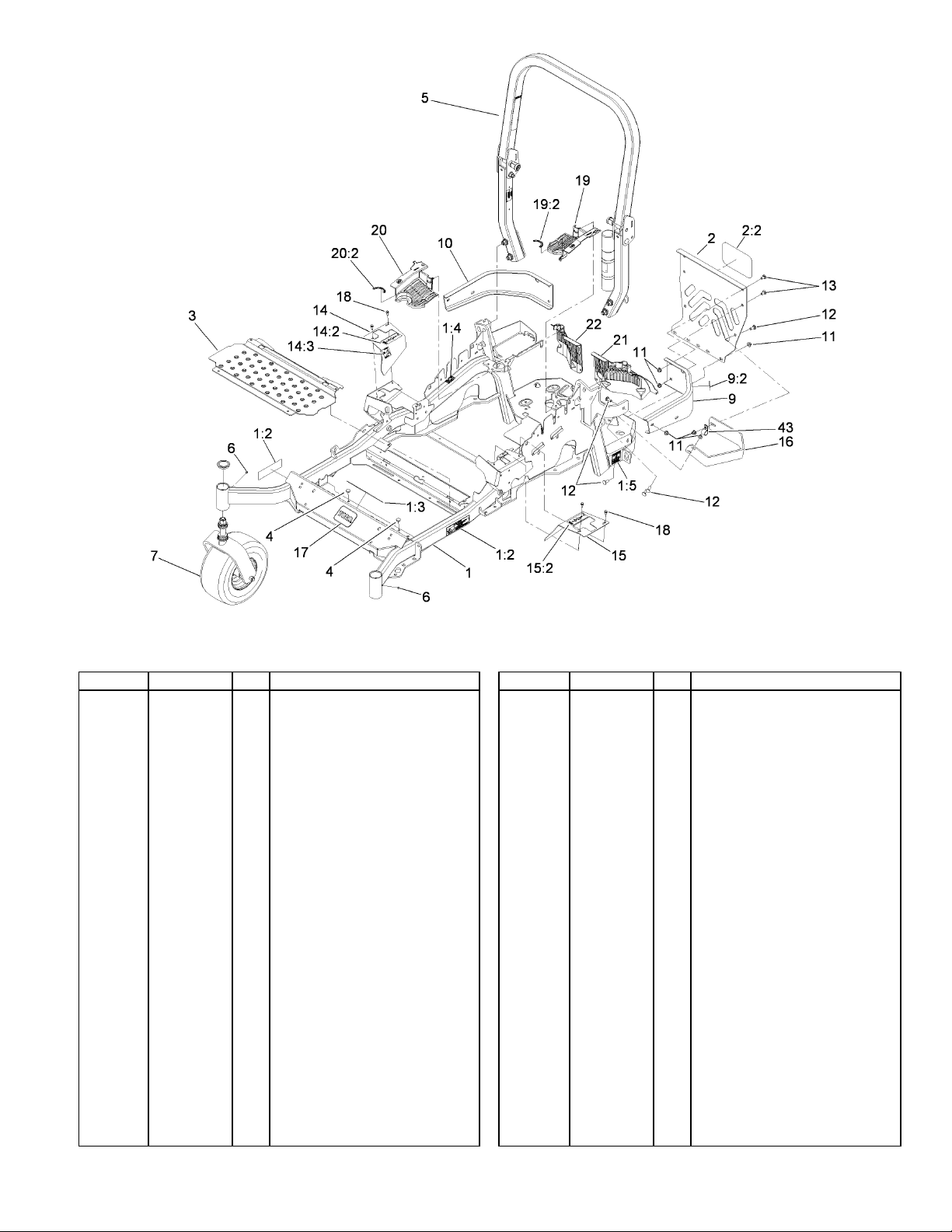
Front Frame and Caster Wheel Assembly
Ref Part No. Qty. Description
Main Frame ASM1
11
1
Decal-Warning1:2
2
Decal-Warning1:3
1
Decal-Caution1:4
2
Decal-Belt Drive1:5
2
Rear Guard ASM2
1
Decal2:2
1
Floorpan3
1
Bumper4
2
ROPS ASM5
1
Plug6
2
Caster Wheel ASM7
2
LH Bumper ASM9
1
Decal-Caution9:2
1
Bumper-RH10
1
Nut-Flange, NI11
Screw-CARR12
7
Screw-CARR13
4
RH Motion Control Cover ASM14
1
Decal-Motion Control14:2
1
Decal-Park Brake14:3
1
LH Motion Control Cover ASM15
1
Decal-Motion Control15:2
1
Guard-Muffler16
1
109-7349
109-9477
107-2112
103-2076
116-0205
115-7410
67-7320
116-0024-01
1-513658
116-0232
1-811010
o
116-0180
103-2076
116-0057-03
104-8301
3231-22
3231-21
116-0579
109-7232
109-7929
116-0580
109-7232
116-0043-03
4
Ref Part No. Qty. Description
1
68-3640
32144-10
116-0170
116-0157
116-0171
116-0157
109-9057
109-9058
1-633396
Decal17
Screw-HWH18
4
LH Hydro Guard ASM19
1
Decal-Hydro Oil19:2
1
RH Hydro Guard ASM20
1
Decal-Hydro Oil20:2
1
Guard-Hydro, Rear LH21
1
Guard-Hydro, Rear RH22
1
Clip-Loom43
1
A1
3360-671 Rev A
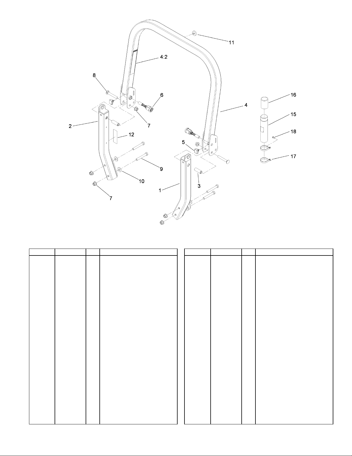
Roll-Over Protection System Assembly No. 116-0232
Ref Part No. Qty. Description
o
o
109-6653
o
107-3069
109-5337
116-0104
99-5107
3233-10
325-17
109-9505
109-9233
117-0346
104-7050
104-7048
107-1865
32144-10
Leg-ROPS, LH11
Leg-ROPS, RH21
Spacer3
2
Upper ROPS ASM41
Decal-Warning, Folding ROPS4:2
1
Bumper-ROPS5
2
Spring Pin ASM6
2
Nut-Lock7
6
Screw-CARR8
2
Screw-HH9
4
Washer-Spring10
4
Bumper-Push-In, Rubber11
1
Decal-Caution, Fuel Vent12
1
Tube-Manual15
1
Cap-Housing16
1
R-Clamp17
2
Screw-HWH18
2
5
3360-671 Rev A
A2
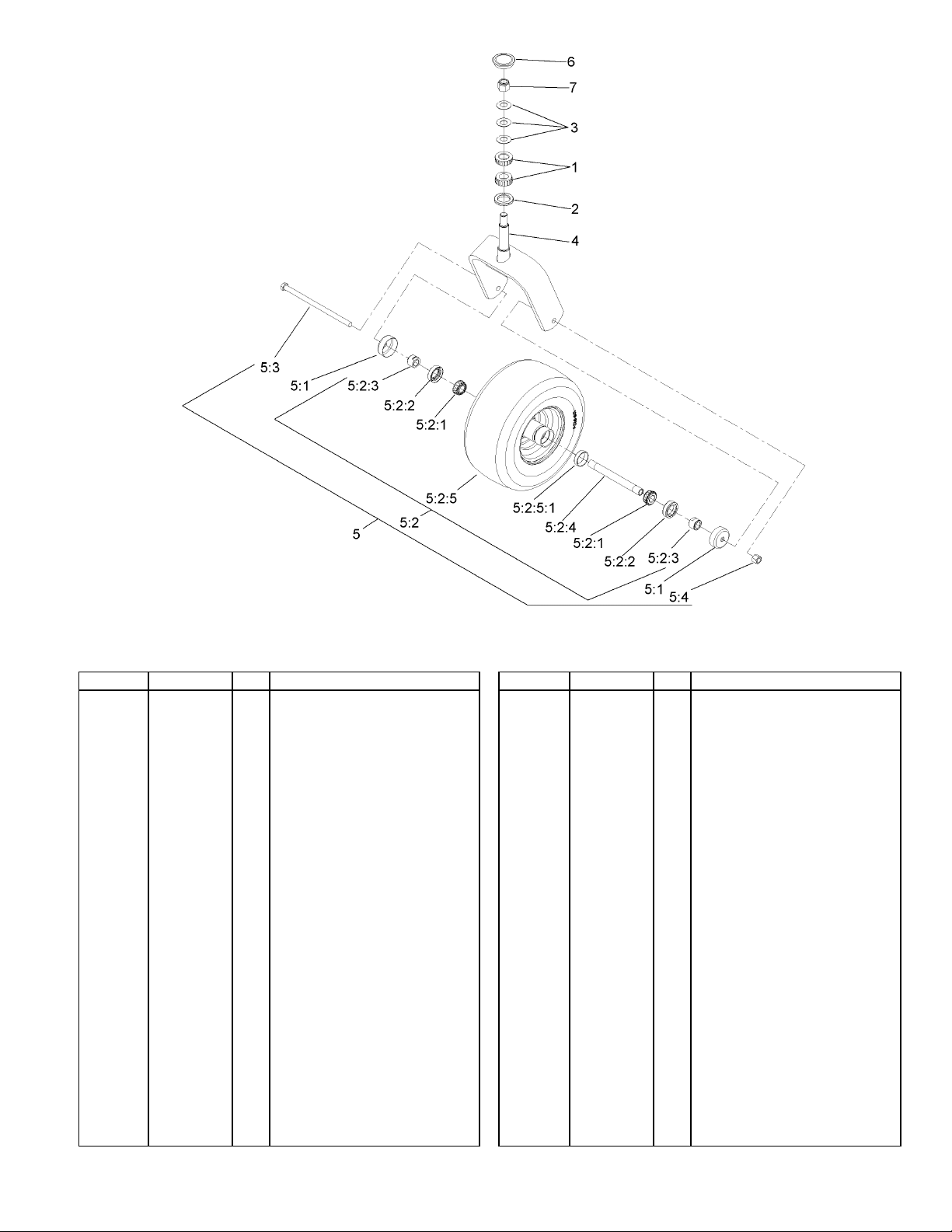
Caster Wheel and Fork Assembly
Ref Part No. Qty. Description
Bearing-Roller, Tapered1
1-543509
1-543511
1-633508
103-1474-01
109-9127
103-2768
o
1-633585
103-0063
103-3051
103-5156
109-9124
1-633584
325-39
3296-23
103-4882
3296-51
2
Seal-Grease2
1
Washer-Bellville3
3
Caster-Fork4
1
Wheel And Tire ASM5
1
Guard-Seal5:1
2
Wheel And Tire ASM5:2
1
Bearing-Cone, Taper5:2:1
2
Seal-Caster5:2:2
2
Spacer-Nut5:2:3
2
Axle-Caster5:2:4
1
Wheel And Tire ASM5:2:5
1
Bearing-Cup5:2:5:1
1
Screw-HH5:3
1
Nut-Lock, NI5:4
1
Cap-Grease6
1
Nut-Lock, NI7
1
6
3
3360-671 Rev A
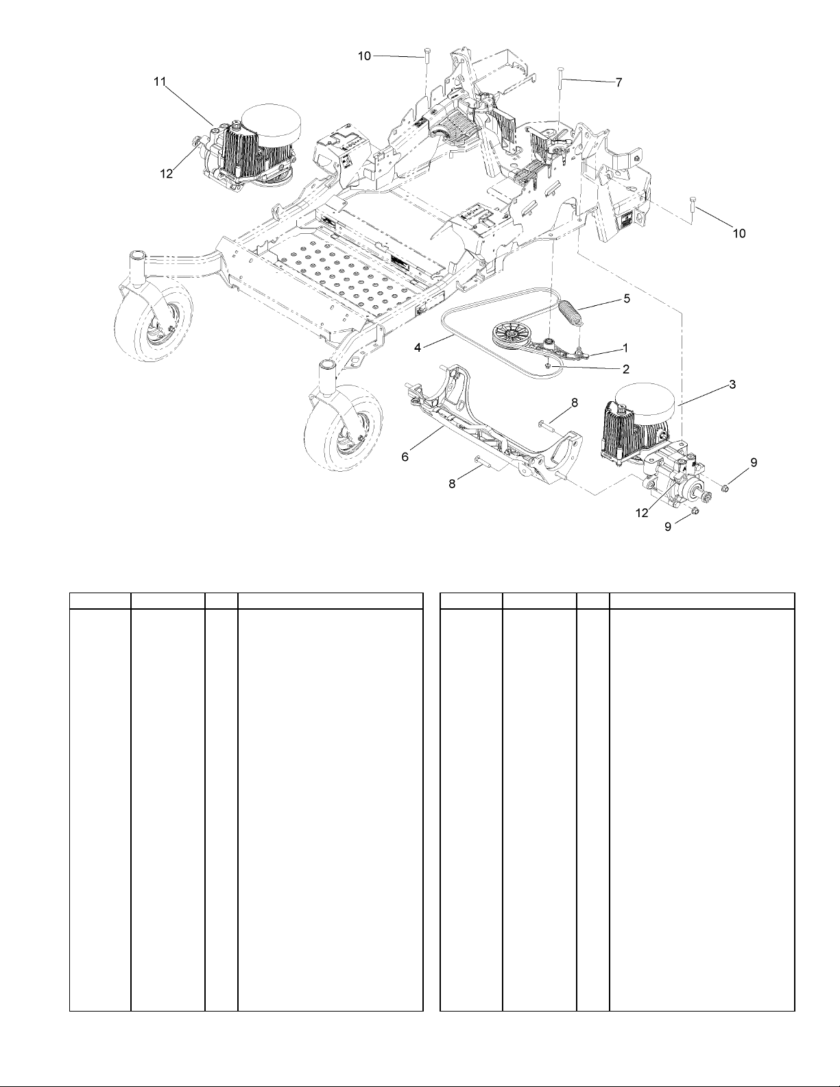
Hydraulic Pump, Idler and Belt Assembly
Ref Part No. Qty. Description
Pump Idler ASM1
116-1255
109-6658
116-1382
109-3388
116-0133
109-9375
3231-41
3233-34
99-5107
325-8
116-1383
116-1758
n
n
n
n
114-4713
114-4714
114-4715
117-0390
1
Nut-Flange, NI (Split)2
1
LH Hydro ASM (16Cc W/Shock)3
1
Belt4
1
Extension-Spring5
1
Cradle-Hydro, Machined6
1
Bolt-Carriage7
1
Screw-CARR8
6
Nut-Lock9
6
Screw-HH10
4
RH Hydro ASM (16Cc W/Shock)11
1
Bracket-Anchor, Cable12
2
Hypr-Oil 500 (Quart)99
1
Hypr-Oil 500 (Gallon)99
1
Hypr-Oil 500-5 (5 Gallon)99
1
Filter-Hydro99
1
7
3360-671 Rev A
A3
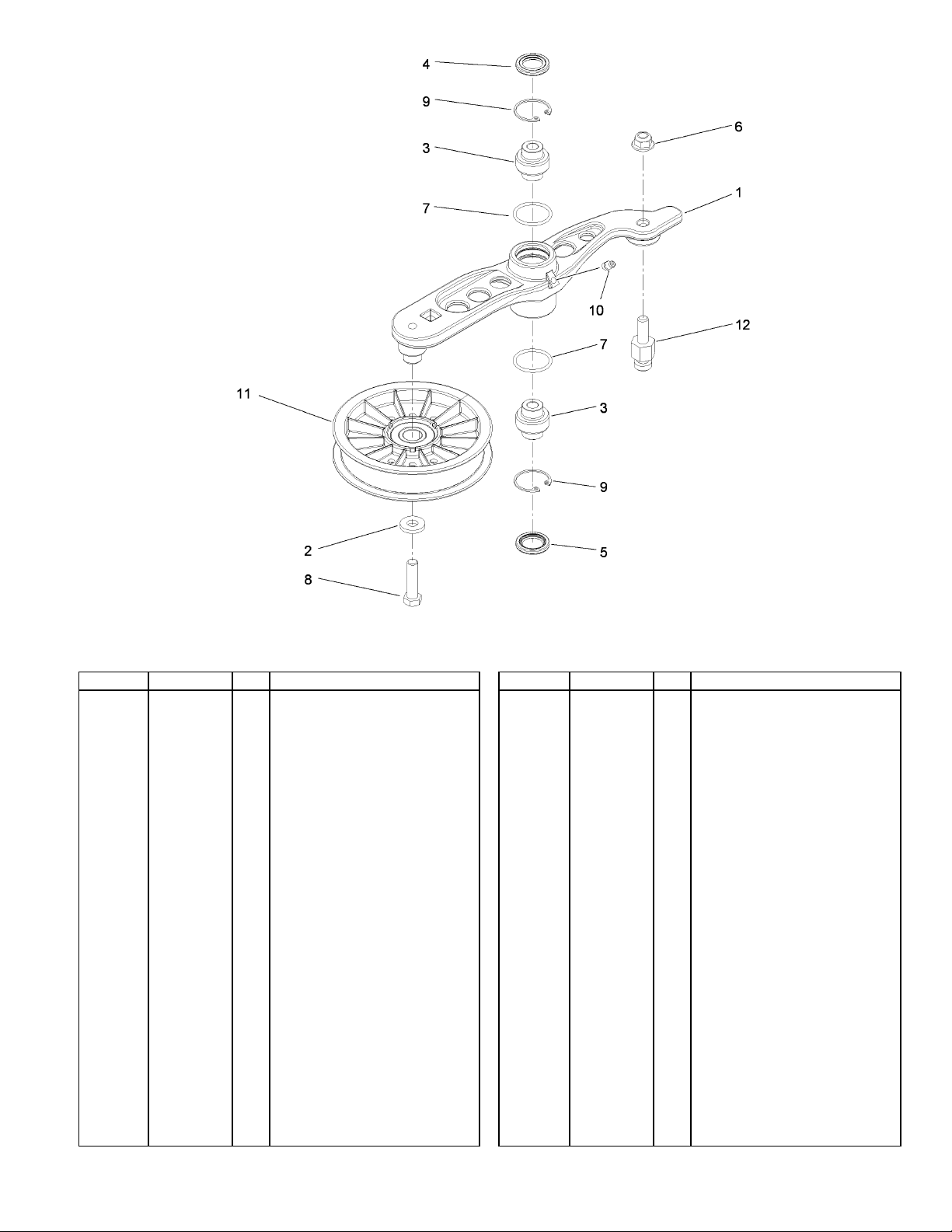
Pump Ilder Assembly No. 116-1255
Ref Part No. Qty. Description
o
43-0940
103-3504
103-3505
103-3506
109-6658
106-7159
323-8
32120-10
302-19
109-8076
109-7399
Arm-Pump, Idler11
Spacer-Hub, Blower2
1
Bearing-Spherical3
2
Seal-Double Lip4
1
Seal-Sing l e L i p5
1
Nut-Flange, NI (Split)6
1
O-Ring7
2
Screw-HH8
1
Ring-Snap9
2
Fitting-Grease10
1
Pulley-Idler11
1
Pin-Anchor, Spring12
1
8
A4
3360-671 Rev A
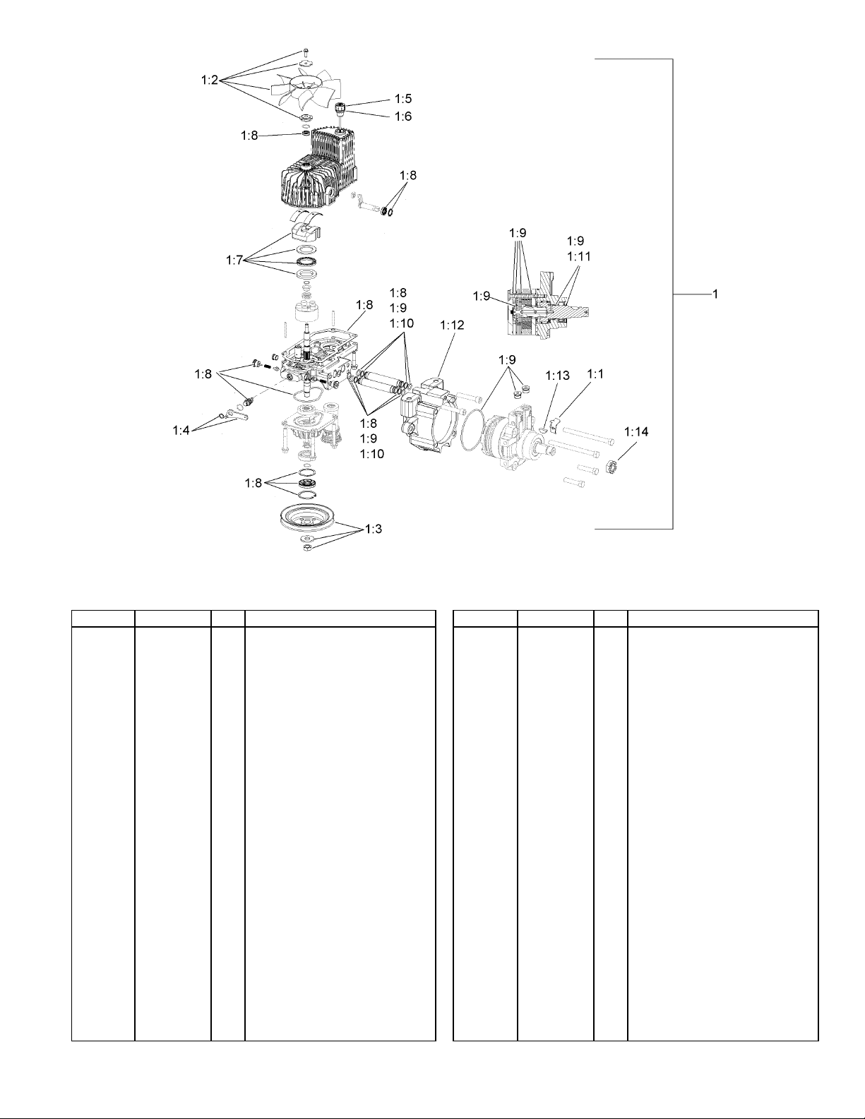
LH Hydro Assembly No. 116-1382
Ref Part No. Qty. Description
o
n
116-1758
116-0233
116-0234
116-0235
116-0236
116-0237
116-1367
116-1368
116-1369
116-1370
116-1371
116-1372
3257-42
1-809036
116-1373
Hydro-LH1
1
Bracket-Anchor, Cable1:1
1
Fan Kit1:2
1
Pulley Kit1:3
1
Handle-Bypass Valve, Hydro1:4
1
Dipstick-Hydro W/Gasket1:5
1
Gasket-Dipstick, Hydro1:6
1
Swash Block Kit1:7
1
Pump Seal Kit1:8
1
Motor Seal Kit1:9
1
Tube Seal Kit1:10
1
Output Shaft Seal Kit1:11
1
Cup-Nose1:12
1
Key-Woodruff1:13
1
Nut-HH1:14
1
Flow Test Kit1:99
1
9
3360-671 Rev A
A5
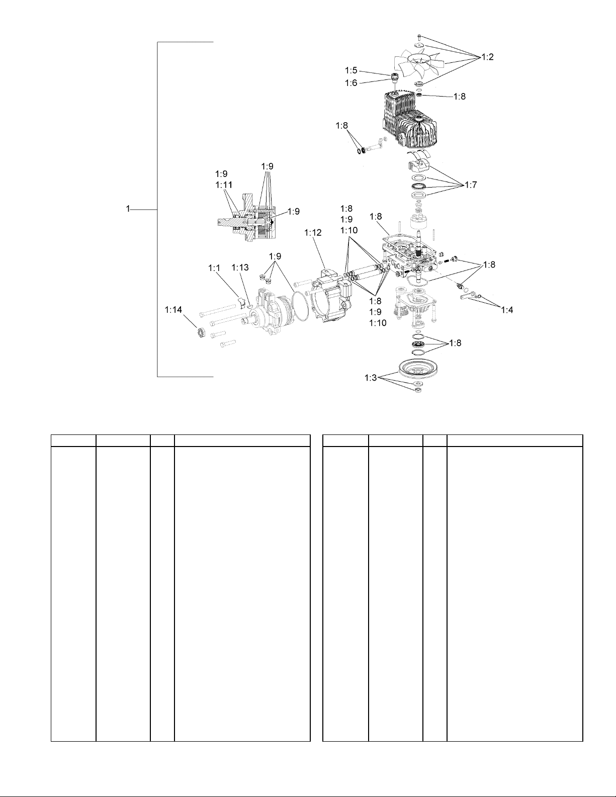
RH Hydro Assembly No. 116-1383
Ref Part No. Qty. Description
o
n
116-1758
116-0233
116-0234
116-0235
116-0236
116-0237
116-1367
116-1368
116-1369
116-1370
116-1371
116-1372
3257-42
1-809036
116-1373
Hydro-RH1
1
Bracket-Anchor, Cable1:1
1
Fan Kit1:2
1
Pulley Kit1:3
1
Handle-Bypass Valve, Hydro1:4
1
Dipstick-Hydro W/Gasket1:5
1
Gasket-Dipstick, Hydro1:6
1
Swash Block Kit1:7
1
Pump Seal Kit1:8
1
Motor Seal Kit1:9
1
Tube Seal Kit1:10
1
Output Shaft Seal Kit1:11
1
Cup-Nose1:12
1
Key-Woodruff1:13
1
Nut-HH1:14
1
Flow Test Kit1:99
1
10
4
3360-671 Rev A
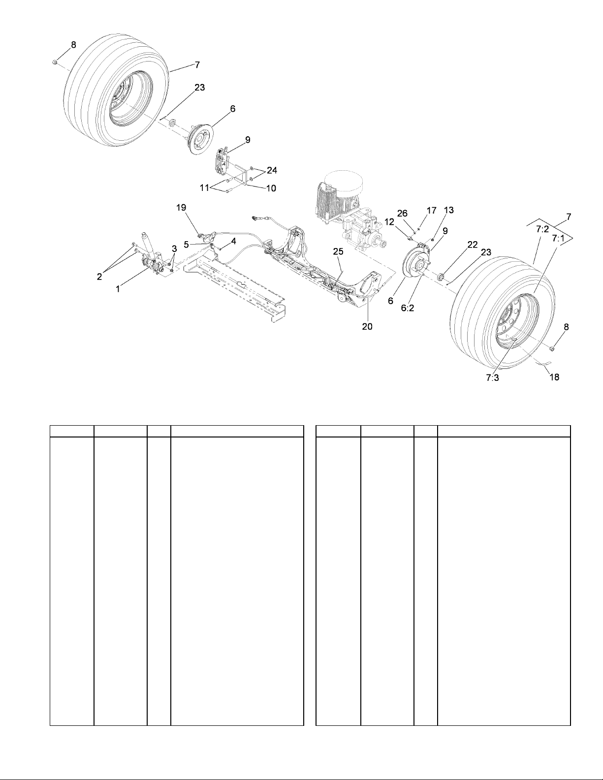
Rear Wheel and Park Brake Assembly
Ref Part No. Qty. Description
Brake Handle ASM1
116-1878
3230-2
104-8300
60-1730
3272-1
117-6163
1-633926
109-3158
109-3156
103-2744
232-27
242-50
109-2889
109-0958
323-7
112-8379
104-7201
3296-13
116-0165
115-3584
115-3585
1-809036
1-806800
3256-24
1
Bolt-CARR2
2
Nut-Flange, NI3
2
Pin-Clevis4
2
Pin-Cotter5
2
Wheel Hub And Stud ASM6
2
Stud-Wheel6:2
4
Wheel & Tire ASM7
2
Rim ASM7:1
1
Tire7:2
1
Stem-Valve7:3
1
Nut-Lug8
8
Caliper-Brake9
2
Plate-Mount, Brake10
2
Screw-HH11
4
Swivel12
2
Nut-HF13
2
Nut-Lock NI17
2
Decal-Hub, Wheel18
2
Cable19
1
Cable20
1
Nut-HH22
2
Pin-Cotter23
2
Washer-Flat24
4
Ref Part No. Qty. Description
1
116-0940
3219-1
Tie-Cable25
Nut-Hex26
2
11

3360-671 Rev A
A6
Brake Handle Assembly No. 116-1878
Ref Part No. Qty. Description
Nut-Lock1
99-5107
117-0380
115-3580
117-0376
115-3574
104-7201
116-1876-03
114-1207
114-8187
115-3581
115-3592
112-8387
117-0375
115-3579
117-0379
117-0378
115-2750
1
Spacer2
1
Arm-Brake, LH3
1
Spring-Torsion, RH4
1
Plate-Latch5
1
Nut-HF6
1
Brake Handle ASM7
1
Washer-Special8
1
Spring-Compression9
1
Rod-Release, Brake10
1
Grip11
1
Bolt-Shoulder12
1
Spring-Torsion, LH13
1
Arm-Brake, RH14
1
Bolt-Shoulder15
1
Washer16
1
Knob17
1
12
5
3360-671 Rev A
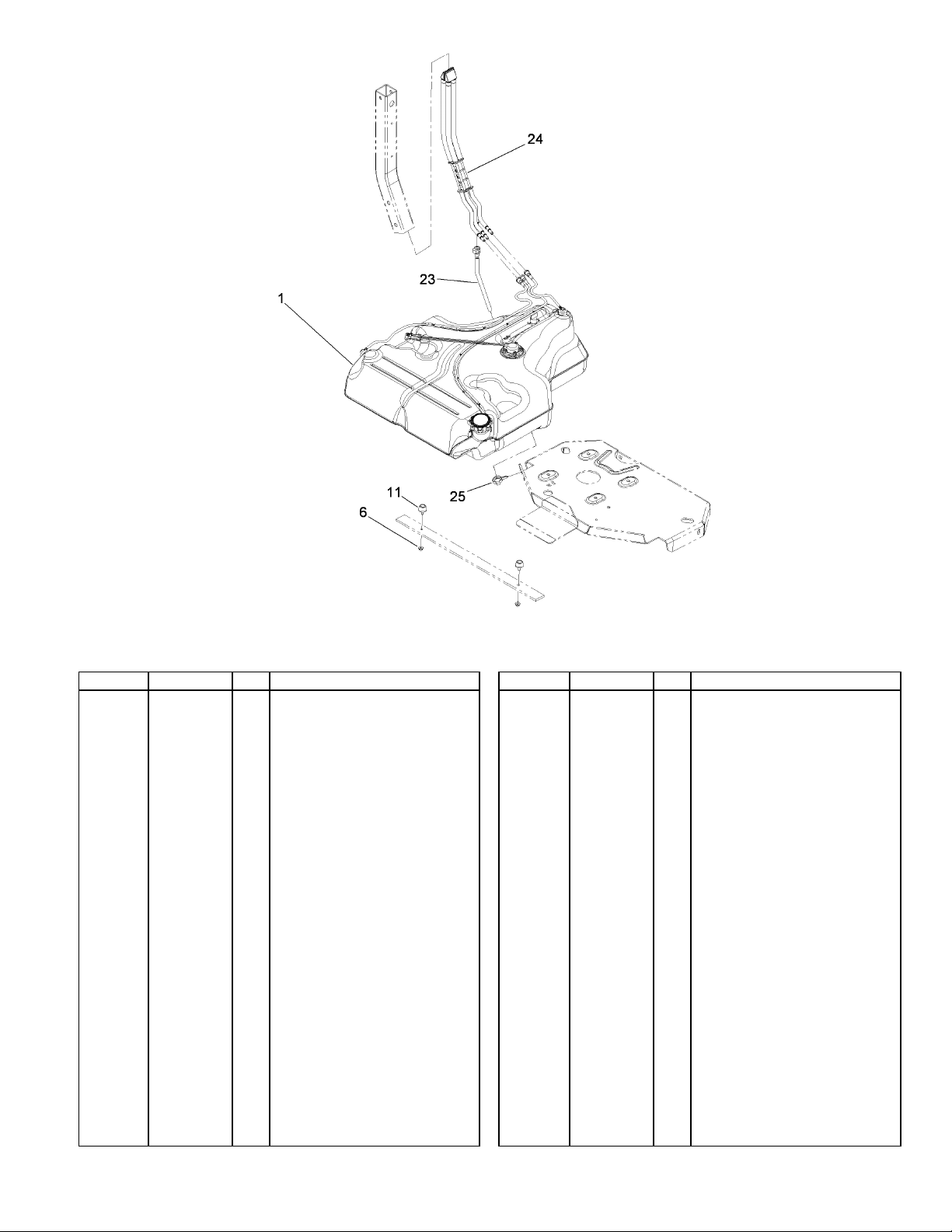
Ref Part No. Qty. Description
Fuel Tank ASM (W/O Sender)1
109-9656
109-9357
32128-33
109-2365
109-9450
109-9491
105-1853
1
Fuel Tank ASM1
1
Nut-HF6
2
Bumper-Rubber (W/Stud)11
2
Tube-Vent, Fuel Drain23
1
Fuel Manifold Vent ASM24
1
Clamp-Hose25
1
Fuel System Assembly
13
3360-671 Rev A
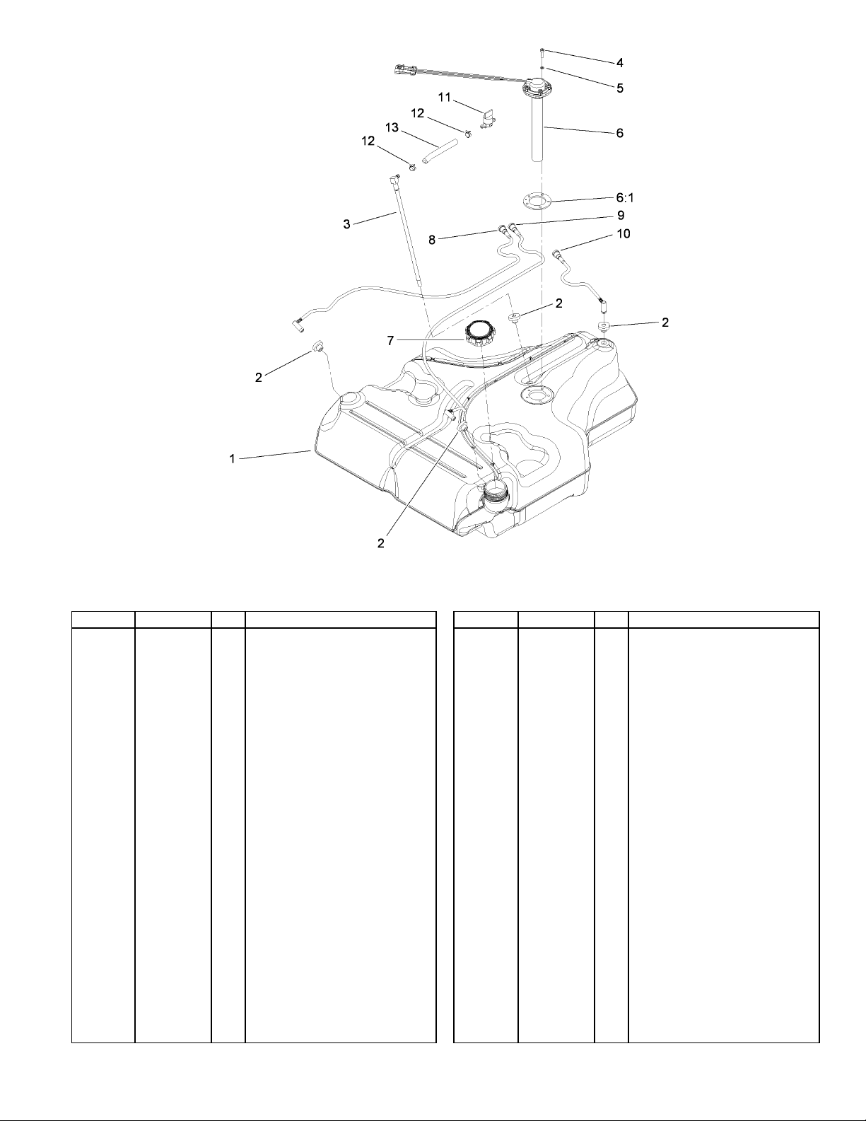
A7
Fuel Tank Assembly No. 109-9357
Ref Part No. Qty. Description
o
46-6560
109-9364
9107944
3253-17
116-0003
109-9620
109-9619
109-9447
109-9448
109-9449
1-603770
2412-98
109-0650
Tank-Fuel, Belly11
Bushing2
4
Fitting-Fuel (W/Line And Screen)3
1
Screw-Pan4
5
Washer-Lock5
5
Sender-Fuel Level6
1
Gasket-Sender, Fuel6:1
1
Cap-Fuel7
1
Tube-Vent, RH8
1
Tube-Vent, LH9
1
Tube-Vent, Rear10
1
Valve-Fuel11
1
Clamp12
2
Hose-Fuel13
1
14
6
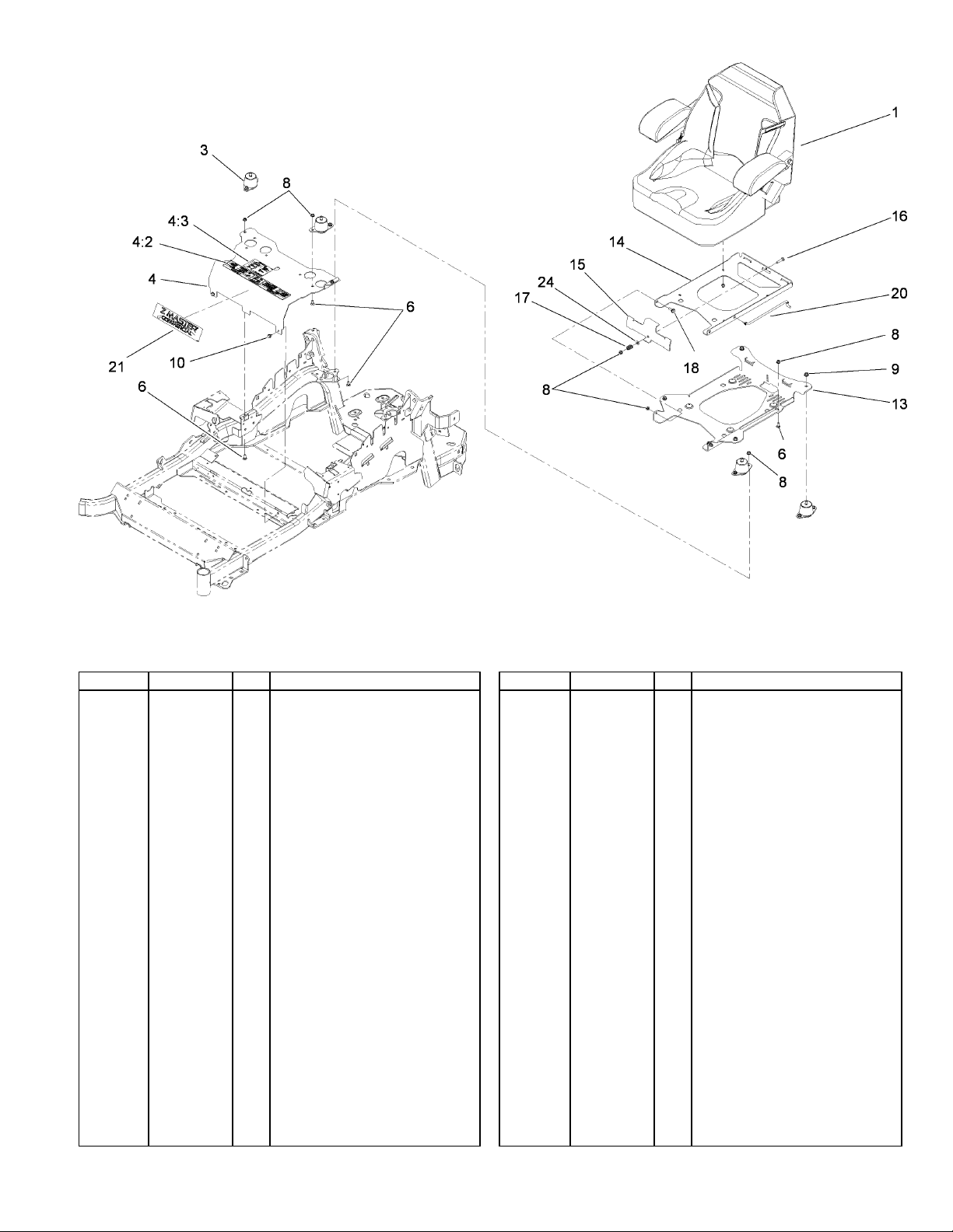
3360-671 Rev A
Seat Mounting Assembly
Ref Part No. Qty. Description
Seat-Standard1
11
18
1
Isolator-Seat3
4
Mount-Seat4
1
Decal-Console4:2
1
Decal-Service Aid4:3
1
Screw-CARR6
Nut-Flange, NI8
Nut-Flange, NI9
4
Screw10
2
Plate-Support, Seat Tilt13
1
Plate-Frame, Seat Tilt14
1
Plate-Latch, Seat15
1
Screw-CARR16
1
Spring-Compression17
1
Screw, Shoulder18
2
Rod-Prop20
1
Decal-Dash21
1
Washer-Flat24
1
116-0035
109-9034
109-9036
109-7069
116-0211
3230-23
104-8300
104-8301
9266934
116-0181-03
116-0179-03
109-9881-03
3230-4
107-3017
116-1297
116-0070
114-5878
3256-23
15
 Loading...