

Page 1
FormNo.3367-967RevD
ZMaster
®
G3RidingMower
witha48inor52inTURBOFORCE
DischargeMower
ModelNo.74951—SerialNo.311000001andUp
ModelNo.74952—SerialNo.311000001andUp
ModelNo.74953—SerialNo.311000001andUp
®
Side
ToregisteryourproductordownloadanOperator'sManualorPartsCatalogatnocharge,gotowww.Toro.com.OriginalInstructions(EN)
Page 2
WARNING
agriculturaluses.
properties.Itisnotdesignedforcuttingbrushorfor
CALIFORNIA
Proposition65Warning
Theengineexhaustfromthisproduct
containschemicalsknowntotheStateof
Californiatocausecancer,birthdefects,
orotherreproductiveharm.
ThissparkignitionsystemcomplieswithCanadian
ICES-002
Becauseinsomeareastherearelocal,state,orfederal
regulationsrequiringthatasparkarresterbeusedonthe
engineofthismachine,asparkarresterisavailableas
anoption.Ifyourequireasparkarrestor,contactyour
AuthorizedToroDealer.
GenuineTorosparkarrestersareapprovedbytheUSDA
ForestryService.
Note:ItisaviolationofCaliforniaPublicResource
CodeSection4442touseoroperatetheengineon
anyforest-covered,brush-covered,orgrass-covered
landwithoutasparkarrestermufermaintainedin
workingorder,ortheengineconstricted,equipped,and
maintainedforthepreventionofre.Otherstatesor
federalareasmayhavesimilarlaws.
Readthisinformationcarefullytolearnhowtooperate
andmaintainyourproductproperlyandtoavoidinjury
andproductdamage.Youareresponsibleforoperating
theproductproperlyandsafely.
YoumaycontactTorodirectlyatwww .Toro.comfor
productandaccessoryinformation,helpndingadealer,
ortoregisteryourproduct.
Wheneveryouneedservice,genuineToroparts,
oradditionalinformation,contactanAuthorized
ServiceDealerorToroCustomerServiceandhave
themodelandserialnumbersofyourproductready .
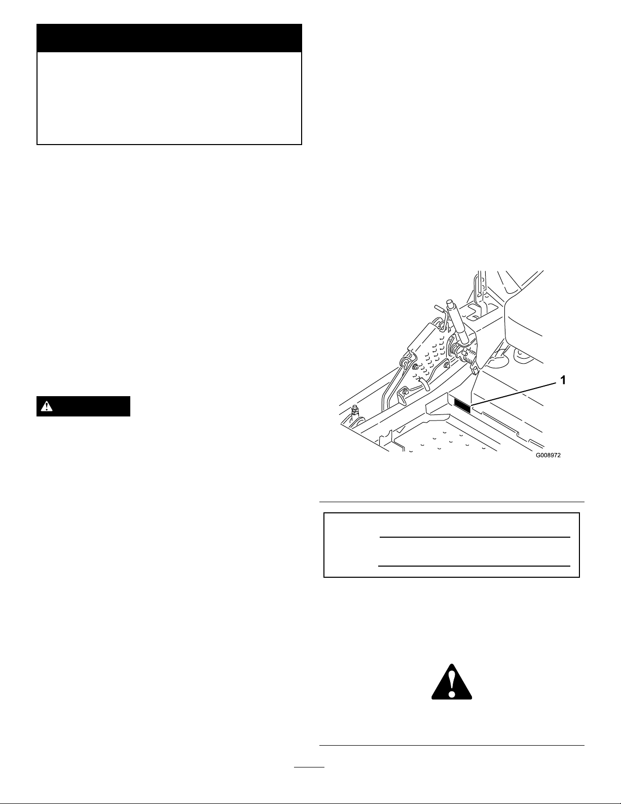
Figure1identiesthelocationofthemodelandserial
numbersontheproduct.Writethenumbersinthe
spaceprovided.
WARNING
Removingstandardoriginalequipmentpartsand
accessoriesmayalterthewarranty,traction,and
safetyofthemachine.FailuretouseoriginalT oro
partscouldcauseseriousinjuryordeath.Making
unauthorizedchangestotheengine,fuelorventing
system,mayviolateEPAandCARBregulations.
Replaceallpartsincluding,butnotlimitedto,tires,
belts,blades,andfuelsystemcomponentswith
originalT oroparts.
Theenclosed
Engine Owner's Man ual
issupplied
forinformationregardingtheUSEnvironmental
ProtectionAgency(EPA)andtheCalifornia
EmissionControlRegulationofemissionsystems,
maintenance,andwarranty.Replacementsmaybe
orderedthroughtheenginemanufacturer.
Introduction
Thisrotary-blade,ridinglawnmowerisintendedtobe
usedbyresidentialhomeownersorprofessional,hired
operators.Itisdesignedprimarilyforcuttinggrasson
well-maintainedlawnsonresidentialorcommercial
©2011—TheToro®Company
8111LyndaleAvenueSouth
Bloomington,MN55420
Figure1
1.Modelandserialnumberlocation
ModelNo.
SerialNo.
Thismanualidentiespotentialhazardsandhassafety
messagesidentiedbythesafetyalertsymbol(Figure2),
whichsignalsahazardthatmaycauseseriousinjury
ordeathifyoudonotfollowtherecommended
precautions.
Figure2
1.Safetyalertsymbol
Contactusatwww.Toro.com.
2
PrintedintheUSA.
AllRightsReserved
Page 3

Thismanualuses2otherwordstohighlightinformation.
Importantcallsattentiontospecialmechanical
informationandNoteemphasizesgeneralinformation
worthyofspecialattention.
Contents
Introduction.................................................................2
Safety...........................................................................4
SafeOperatingPractices.......................................4
SlopeIndicator.....................................................6
SafetyandInstructionalDecals.............................7
ProductOverview......................................................12
Controls.............................................................12
Specications.....................................................13
Operation...................................................................14
AddingFuel.......................................................14
CheckingtheEngineOilLevel............................15
BreakingInaNewMachine................................15
UsingtheRolloverProtectionSystem
(ROPS)..........................................................15
ThinkSafetyFirst...............................................16
OperatingtheParkingBrake...............................17
OperatingtheMowerBladeControlSwitch
(PTO)............................................................17
OperatingtheThrottle.......................................18
OperatingtheChoke..........................................18
OperatingtheIgnitionSwitch.............................18
UsingtheFuelShut-OffValve............................18
StartingandStoppingtheEngine........................19
TheSafetyInterlockSystem................................20
DrivingForwardorBackward.............................21
StoppingtheMachine.........................................22
AdjustingtheHeightofCut................................22
AdjustingtheAnti-ScalpRollers.........................23
AdjustingtheFlowBafeCamLocks..................24
PositioningtheFlowBafe.................................24
PositioningtheSeat............................................25
UsingtheDriveWheelReleaseValves.................25
UsingtheSideDischarge....................................26
TransportingMachines.......................................26
LoadingMachines..............................................27
OperatingTips...................................................28
Maintenance...............................................................30
RecommendedMaintenanceSchedule(s)................30
Lubrication.............................................................31
GreasingandLubrication...................................31
WheretoGreasetheMower...............................31
LubricateCasterWheelHubs.............................32
EngineMaintenance...............................................33
ServicingtheAirCleaner....................................33
ServicingtheEngineOil.....................................34
ServicingtheSparkPlug.....................................37
CheckSparkArrester(ifequipped)......................38
FuelSystemMaintenance.......................................38
ReplacingtheFuelFilter.....................................38
ServicingtheFuelTank......................................39
ElectricalSystemMaintenance................................39
ServicingtheBattery...........................................39
ServicingtheFuses.............................................41
DriveSystemMaintenance.....................................42
CheckingtheSeatBelt........................................42
CheckingtheRolloverProtectionSystem
(ROPS)Knobs...............................................42
AdjustingtheTracking........................................42
CheckingtheTirePressure.................................43
CheckingtheWheelHubSlottedNut..................43
AdjustingtheCasterPivotBearing......................44
UsingtheClutchShim........................................44
CoolingSystemMaintenance..................................46
CleaningtheEngineScreenandEngineOil
Cooler............................................................46
CleaningtheEngineCoolingFinsand
Shrouds..........................................................46
CheckandCleantheHydraulicUnits..................47
BrakeMaintenance.................................................48
AdjustingtheParkingBrake................................48
BeltMaintenance....................................................49
InspectingtheBelts............................................49
ReplacingtheMowerBelt...................................49
ReplacingtheHydraulicPumpDrive
Belt................................................................50
ControlsSystemMaintenance.................................51
AdjustingtheControlHandlePosition................51
AdjustingtheMotionControlLinkage................51
AdjustingtheMotionControlDamper...............52
AdjustingtheMotionControlNeutralLock
Pivot..............................................................52
HydraulicSystemMaintenance...............................53
ServicingtheHydraulicSystem...........................53
MowerDeckMaintenance......................................55
LevelingtheMowerDeck...................................55
ServicingtheCuttingBlades...............................57
RemovingtheMowerDeck................................60
ReplacingtheGrassDeector.............................61
Cleaning.................................................................62
CleaningUndertheMower.................................62
WasteDisposal...................................................62
Storage.......................................................................62
CleaningandStorage..........................................62
Troubleshooting.........................................................64
Schematics.................................................................66
3
Page 4

Safety
•Useextracarewhenhandlinggasolineandother
fuels.Theyareammableandvaporsareexplosive.
Improperuseormaintenancebytheoperatororowner
canresultininjury.Toreducethepotentialforinjury,
complywiththesesafetyinstructionsandalwayspay
attentiontothesafetyalertsymbol,whichmeans
CAUTION,WARNING,orDANGER-“personal
safetyinstruction."Failuretocomplywiththeinstruction
mayresultinpersonalinjuryordeath.
Thisproductiscapableofamputatinghandsand
feetandthrowingobjects.Alwaysfollowallsafety
instructionstoavoidseriousinjuryordeath.
Thisproductisdesignedforcuttingandrecyclinggrass
or,whenequippedwithagrassbagger,forcatchingcut
grass.Anyuseforpurposesotherthanthesecould
provedangeroustouserandbystanders.
SafeOperatingPractices
ThefollowinginstructionsarefromANSIstandard
B71.4-2004.
Training
•ReadtheOperator'sManualandothertraining
material.Iftheoperator(s)ormechanic(s)cannot
readEnglishitistheowner'sresponsibilitytoexplain
thismaterialtothem.
•Becomefamiliarwiththesafeoperationofthe
equipment,operatorcontrols,andsafetysigns.
•Alloperatorsandmechanicsshouldbetrained.The
ownerisresponsiblefortrainingtheusers.
•Neverletchildrenoruntrainedpeopleoperateor
servicetheequipment.Localregulationsmayrestrict
theageoftheoperator.
•Theowner/usercanpreventandisresponsiblefor
accidentsorinjuriesoccurringtohimselforherself,
otherpeopleorproperty.
–Useonlyanapprovedcontainer
–Neverrefuelordrainthemachineindoors.
–Neverremovegascaporaddfuelwithengine
running.Allowenginetocoolbeforerefueling.
Donotsmoke.
•Checkthatoperator'spresencecontrols,safety
switchesandshieldsareattachedandfunctioning
properly.Donotoperateunlesstheyarefunctioning
properly.
Operation
•Lightningcancausesevereinjuryordeath.If
lightningisseenorthunderisheardinthearea,do
notoperatethemachine;seekshelter.
•Neverrunanengineinanenclosedarea.
•Onlyoperateingoodlight,keepingawayfromholes
andhiddenhazards.
•Besurealldrivesareinneutralandparkingbrakeis
engagedbeforestartingengine.Starttheengineonly
fromtheoperator'sposition.Useseatbelts.
•Neverraisemowerwiththebladesrunning.
•NeveroperatewithoutthePTOshield,orother
guardssecurelyinplace.Besureallinterlocksare
attached,adjustedproperly,andfunctioningproperly.
•Neveroperatewiththedischargedeectorraised,
removedoraltered,unlessusingagrasscatcher.
•Donotchangetheenginegovernorsettingor
overspeedtheengine.
•Stoponlevelground,lowerimplements,disengage
drives,engageparkingbrake,shutoffenginebefore
leavingtheoperator'spositionforanyreason
includingemptyingthecatchersoruncloggingthe
chute.
Preparation
•Evaluatetheterraintodeterminewhataccessories
andattachmentsareneededtoproperlyand
safelyperformthejob.Onlyuseaccessoriesand
attachmentsapprovedbythemanufacturer.
•Wearappropriateclothingincludinghardhat,safety
glassesandhearingprotection.Longhair,loose
clothingorjewelrymaygettangledinmovingparts.
•Inspecttheareawheretheequipmentistobeused
andremoveallobjectssuchasrocks,toysandwire
whichcanbethrownbythemachine.
•Stopequipmentandinspectbladesafterstriking
objectsorifanabnormalvibrationoccurs.Make
necessaryrepairsbeforeresumingoperations.
•Keephandsandfeetawayfromthecuttingunits.
•Nevercarrypassengersandkeeppetsandbystanders
away.
•Bealert,slowdownandusecautionwhenmaking
turns.Lookbehindandtothesidebeforechanging
directions.
•Slowdownandusecautionwhencrossingroadsand
sidewalks.Stopbladesifnotmowing.
4
Page 5

•Beawareofthemowerdischargedirectionanddo
notpointitatanyone.
•Donotoperatethemowerundertheinuenceof
alcoholordrugs.
•Useextremecarewhenloadingorunloadingthe
machineintoatrailerortruck.
•Usecarewhenapproachingblindcorners,shrubs,
trees,orotherobjectsthatmayobscurevision.
SlopeOperation
•Donotmowslopesgreaterthan15degrees.
•Donotmowneardrop-offs,ditches,steepbanks
orwater.Wheelsdroppingoveredgescancause
rollovers,whichmayresultinseriousinjury,death
ordrowning.
•Donotmowslopeswhengrassiswet.Slippery
conditionsreducetractionandcouldcausesliding
andlossofcontrol.
•Donotmakesuddenturnsorrapidspeedchanges.
•Useawalkbehindmowerand/orahandtrimmer
neardrop-offs,ditches,steepbanksorwater.
•Reducespeedanduseextremecautiononslopes.
•Removeormarkobstaclessuchasrocks,treelimbs,
etc.fromthemowingarea.Tallgrasscanhide
obstacles.
•Watchforditches,holes,rocks,dips,andrisesthat
changetheoperatingangle,asroughterraincould
overturnthemachine.
•Avoidsuddenstartswhenmowinguphillbecausethe
mowermaytipbackwards.
•Beawarethatoperatingonwetgrass,acrosssteep
slopes,ordownhillmaycausethemowertolose
traction.Lossoftractiontothedrivewheelsmay
resultinslidingandalossofbrakingandsteering.
•Alwaysavoidsuddenstartingorstoppingona
slope.Iftireslosetraction,disengagethebladesand
proceedslowlyofftheslope.
•Followthemanufacturer'srecommendationsfor
wheelweightsorcounterweightstoimprovestability.
•Useextremecarewithgrasscatchersorother
attachments.Thesecanchangethestabilityofthe
machineandcauselossofcontrol.
UsingtheRolloverProtectionSystem
(ROPS)
•Keeptherollbarintheraisedandlockedposition
andusetheseatbeltwhenoperatingthemachine.
•Becertainthattheseatbeltcanbereleasedquickly
intheeventofanemergency.
•Beawarethereisnorolloverprotectionwhenthe
rollbarisdown.
•Checktheareatobemowedandneverfoldthe
ROPSinareaswherethereareslopes,dropoffsor
water.
•Lowertherollbaronlywhenabsolutelynecessary.
Donotweartheseatbeltwiththerollbarfolded
down.
•Checkcarefullyforoverheadclearances(i.e.
branches,doorways,electricalwires)beforedriving
underanyobjectsanddonotcontactthem.
Maintenanceandstorage
•Disengagedrives,lowerimplement,setparking
brake,stopengineandremovekeyordisconnect
sparkplugwire.Waitforallmovementtostop
beforeadjusting,cleaningorrepairing.
•Cleangrassanddebrisfromcuttingunits,drives,
mufers,andenginetohelppreventres.Cleanup
oilorfuelspillage.
•Letenginecoolbeforestoringanddonotstorenear
ame.
•Shutofffuelwhilestoringortransporting.Donot
storefuelnearamesordrainindoors.
•Parkmachineonlevelground.Neverallowuntrained
personneltoservicemachine.
•Usejackstandstosupportcomponentswhen
required.
•Carefullyreleasepressurefromcomponentswith
storedenergy.
•Disconnectbatteryorremovesparkplugwirebefore
makinganyrepairs.Disconnectthenegativeterminal
rstandthepositivelast.Reconnectpositiverst
andnegativelast.
•Usecarewhencheckingblades.Wraptheblade(s)or
weargloves,andusecautionwhenservicingthem.
Onlyreplacedamagedblades;neverstraightenor
weldthem.
•Keephandsandfeetawayfrommovingparts.If
possible,donotmakeadjustmentswiththeengine
running.
•Chargebatteriesinanopenwellventilatedarea,
awayfromsparkandames.Unplugchargerbefore
connectingordisconnectingfrombattery.Wear
protectiveclothinganduseinsulatedtools.
•Keepallpartsingoodworkingconditionandall
hardwaretightened.Replaceallwornordamaged
decals.
•UseonlyT oroapprovedattachments.Warrantymay
bevoidedifusedwithunapprovedattachments.
5
Page 6
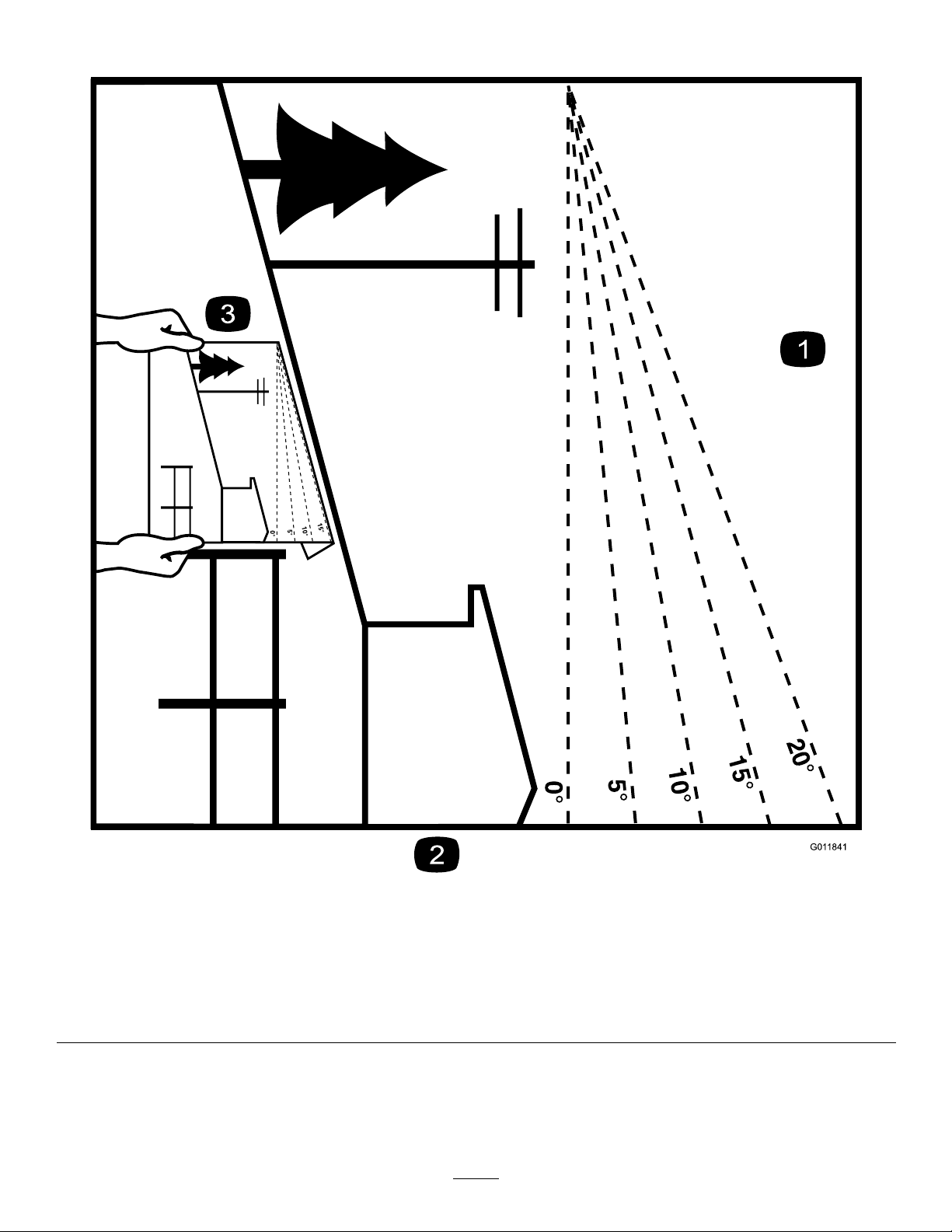
SlopeIndicator
G011841
Figure3
Thispagemaybecopiedforpersonaluse.
1.Themaximumslopeyoucansafelyoperatethemachineonis15degrees.Usetheslopecharttodeterminethedegreeofslope
ofhillsbeforeoperating.Donotoperatethismachineonaslopegreaterthan15degrees.Foldalongtheappropriateline
tomatchtherecommendedslope.
2.Alignthisedgewithaverticalsurface,atree,building,fencepole,etc.
3.Exampleofhowtocompareslopewithfoldededge.
6
Page 7

SafetyandInstructional
Decals
Safetydecalsandinstructionsareeasilyvisibletotheoperatorandarelocatednearanyareaof
potentialdanger.Replaceanydecalthatisdamagedorlost.
68-8340
1-403005
98-5954
103-2076
54-9220
58-6520
1.Grease
105-7798
66-1340
7
Page 8
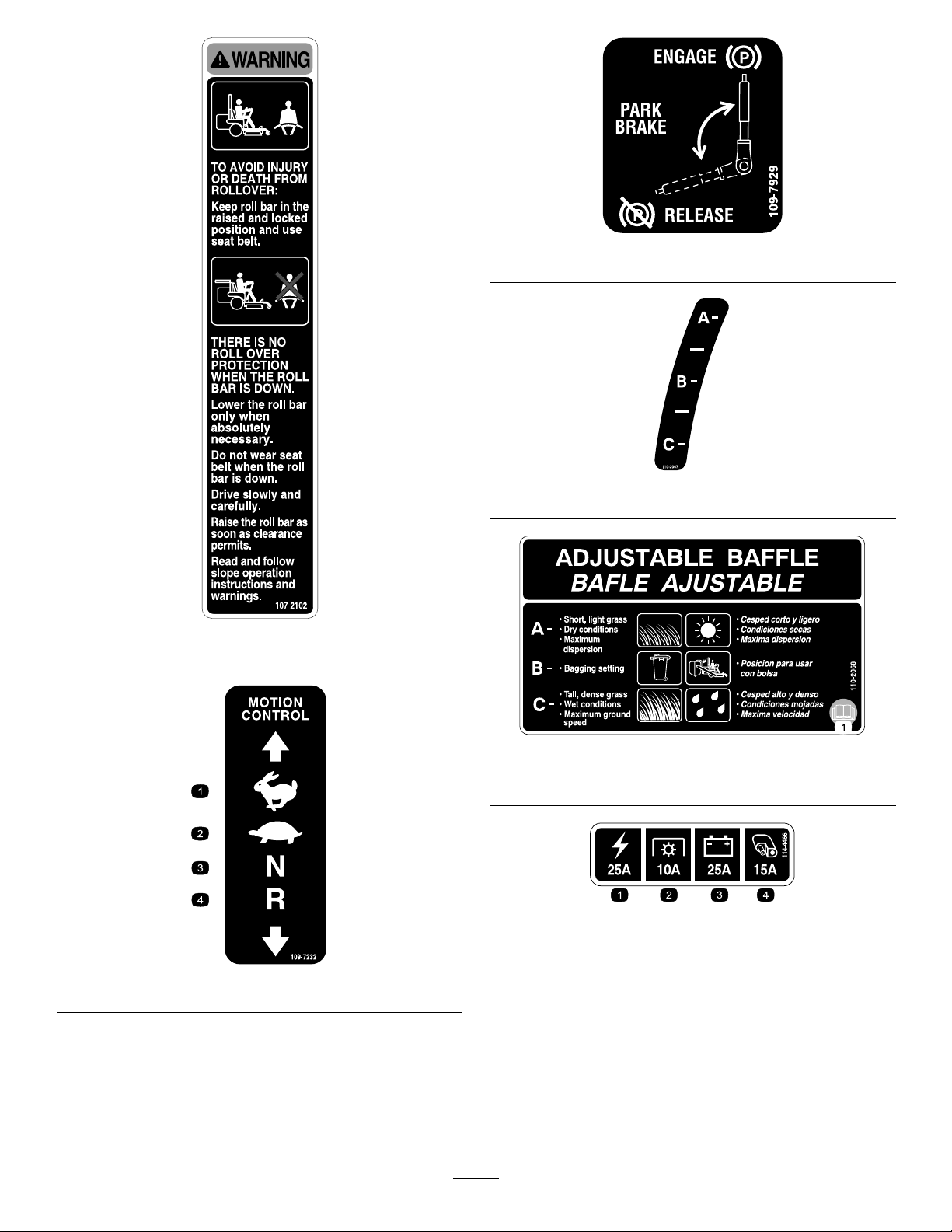
109-7929
110-2067
107-2102
110-2068
1.ReadtheOperator'sManual.
114-4466
1.Main,25A
109-7232
2.PTO,10A
3.Charge,25A
4.Auxiliary,15A
8
Page 9
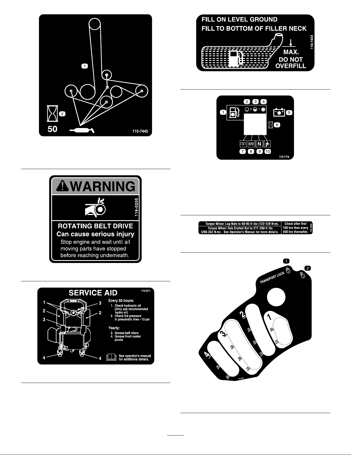
1.Greasepulleysandspindles
2.Maintenanceinterval—50hours
116-1654
115-7445
116-1716
1.Fuel6.Hourmeter
2.Empty
3.Half
4.Full9.Neutral
5.Battery
7.PTO
8.Parkingbrake
10.Operatorpresenceswitch
116-2643
116-0205
116-0211
116-2927
1.Latch
2.Unlatch
9
Page 10
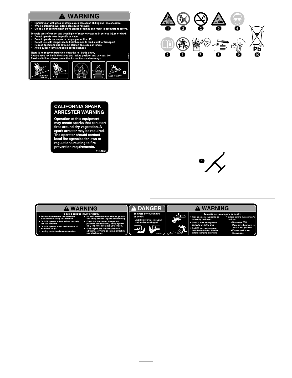
BatterySymbols
Someorallofthesesymbolsareonyourbattery
1.Explosionhazard
116-3303
2.Nore,opename,or
smoking.
3.Causticliquid/chemical
burnhazard
4.Weareyeprotection9.Flusheyesimmediately
5.ReadtheOperator's
Manual.
6.Keepbystandersasafe
distancefromthebattery.
7.Weareyeprotection;
explosivegasescan
causeblindnessandother
injuries
8.Batteryacidcancause
blindnessorsevereburns.
withwaterandgetmedical
helpfast.
10.Containslead;donot
discard.
116-4858
Manufacturer'sMark
1.Indicatesthebladeisidentiedasapartfromtheoriginal
machinemanufacturer.
109-7069
10
Page 11

119-6662
1.Choke4.Continuousvariablesetting
2.PowerT ake-off(PTO)5.Slow
3.Fast
11
Page 12
ProductOverview
G014939
25
25
10
15
G008951
1
2
3
4
5
6
G008950
12
3
4
Usethesetimesforschedulingregularmaintenance
(Figure6).
FuelGauge
Thefuelgaugeislocatedwiththehourmeterandthe
barslightupwhentheignitionswitchison(Figure6).
Theindicatorlightappearswhenthefuellevelislow
(approximatelyonegallonremaininginthefueltank).
SafetyInterlockIndicators
Therearesymbolsonthehourmeterandtheindicate
withablacktrianglethattheinterlockcomponentisin
thecorrectposition(Figure6).
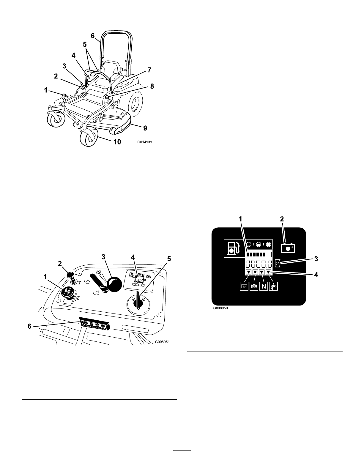
Figure4
1.Height-of-cutdecklift
pedal
2.Transportlock
3.Parkingbrakelever8.Fuelcap
4.Controls
5.Motioncontrollevers
6.Rollbar
7.Seatbelt
9.Mowerdeck
10.Casterwheel
Controls
Becomefamiliarwithallthecontrolsbeforeyoustartthe
engineandoperatethemachine(
Figure4andFigure5).
BatteryIndicatorLight
IftheignitionkeyisturnedtotheOnpositionforafew
seconds,thebatteryvoltagewillbedisplayedinthearea
wherethehoursarenormallydisplayed.
Thebatterylightturnsonwhentheignitionisturned
onandwhenthechargeisbelowthecorrectoperating
level(Figure6).
Figure6
Figure5
1.PTOSwitch4.Hourmeter/Safety
2.Choke
3.Throttlecontrol6.Fuses
5.Ignitionswitch
interlockdisplay/Fuel
gauge
HourMeter
Thehourmeterrecordsthenumberofhourstheengine
hasoperated.Itoperateswhentheengineisrunning.
1.Fuelgauge(bars)4.Safetyinterlocksymbols
2.Batterylight
3.Hourmeter
5.Lowfuelindicatorlight
ThrottleControl
ThethrottlecontrolisvariablebetweenFastandSlow.
Choke
Usethechoketostartacoldengine.Pullthechoke
knobuptoengageit.
12
Page 13
BladeControlSwitch(PTO)
Length:
Thebladecontrolswitch(PTO)isusedtoengagethe
electricclutchanddrivethemowerblades.Pullthe
switchuptoengagethebladesandrelease.Todisengage
theblades,pushthebladecontrolswitch(PTO)down
ormoveamotioncontrolleverintotheneutrallock
position.
IgnitionSwitch
Thisswitchisusedtostartthemowerengineandhas
threepositions:Start,RunandOff.
MotionControlLevers
Themotioncontrolleversareusedtodrivethemachine
forward,reverse,andturneitherdirection.
NeutralLockPosition
Theneutrallockpositionisusedwiththesafetyinterlock
systemtoengageandtodetermineneutralposition.
48inchDeck52inchDeck
RollBar-Up
RollBar-Down
79.2inches(201.2
cm)
80.9inches(205.5
cm)
79.2inches(201.2
cm)
80.9inches(205.5
cm)
Height:
RollBar-UpRollBar-Down
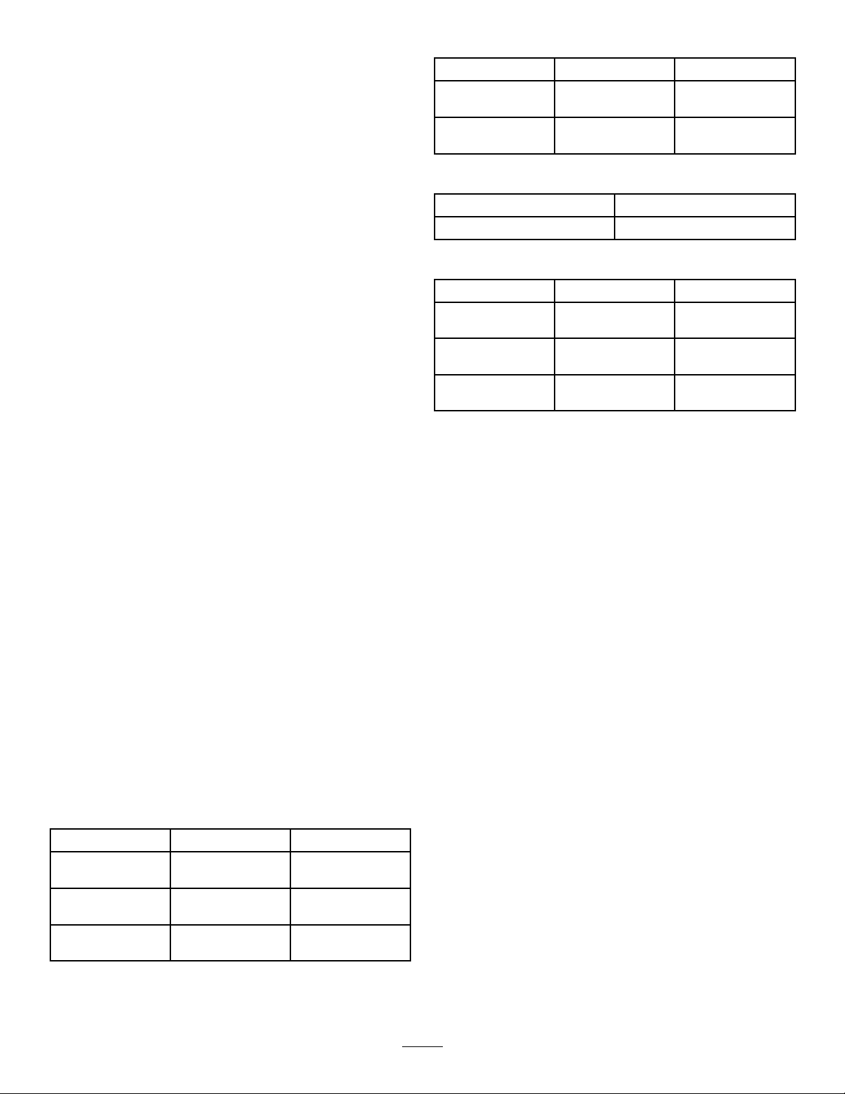
70.5inches(179.1cm)46.8inches(118.9cm)
Weight:
48inchDeck52inchDeck
20HPKawasaki
Units
22HPKawasaki
Units
24HPKawasaki
Units
1048lb(475kg)
1048lb(475kg)
NA
NA
NA
1085lb(492kg)
FuelShut-offValve
Closethefuelshut-offvalve(undertheseat)when
transportingorstoringthemower.
Attachments/Accessories
AselectionofToroapprovedattachmentsand
accessoriesareavailableforusewiththemachineto
enhanceandexpanditscapabilities.Contactyour
AuthorizedServiceDealerorDistributororgoto
www.Toro.comforalistofallapprovedattachments
andaccessories.
Specications
Note:Specicationsanddesignaresubjecttochange
withoutnotice.
Width:
48inchDeck52inchDeck
WithoutDeck
DeectorUp54inches(137.2
DeectorDown63.55inches(161.4
45.7inches(116.1
cm)
cm)57.5
cm)
45.7inches(116.1
cm)
57.5inches(146.0
cm)
67.63inches(171.8
cm)
13
Page 14

Operation
Note:Determinetheleftandrightsidesofthe
machinefromthenormaloperatingposition.
AddingFuel
Useunleadedregulargasolinesuitableforautomotive
use(85pumpoctaneminimum).Leadedregular
gasolinemaybeusedifunleadedregularisnotavailable.
Important:Neverusemethanol,gasoline
containingmethanol,orgasoholcontainingmore
than10%ethanolbecausethefuelsystemcouldbe
damaged.Donotmixoilwithgasoline.
DANGER
Incertainconditions,gasolineisextremely
ammableandhighlyexplosive.Areorexplosion
fromgasolinecanburnyouandothersandcan
damageproperty.
DANGER
Incertainconditionsduringfueling,static
electricitycanbereleasedcausingasparkwhich
canignitethegasolinevapors.Areorexplosion
fromgasolinecanburnyouandothersandcan
damageproperty.
•Alwaysplacegasolinecontainersontheground
awayfromyourvehiclebeforelling.
•Donotllgasolinecontainersinsideavehicle
oronatruckortrailerbedbecauseinterior
carpetsorplastictruckbedlinersmayinsulate
thecontainerandslowthelossofanystatic
charge.
•Whenpractical,removegas-powered
equipmentfromthetruckortrailerandrefuel
theequipmentwithitswheelsontheground.
•Ifthisisnotpossible,thenrefuelsuch
equipmentonatruckortrailerfromaportable
container,ratherthanfromagasolinedispenser
nozzle.
•Fillthefueltankoutdoorsonlevelground,in
anopenarea,whentheengineiscold.Wipeup
anygasolinethatspills.
•Neverllthefueltankinsideanenclosedtrailer.
•Donotllthefueltankcompletelyfull.Fill
thefueltanktothebottomofthellerneck.
Theemptyspaceinthetankallowsgasolineto
expand.Overllingmayresultinfuelleakage
ordamagetotheengineoremissionsystem(if
equipped).
•Neversmokewhenhandlinggasoline,andstay
awayfromanopenameorwheregasoline
fumesmaybeignitedbyaspark.
•Storegasolineinanapprovedcontainerand
keepitoutofthereachofchildren.Neverbuy
morethana30-daysupplyofgasoline.
•Donotoperatewithoutentireexhaustsystem
inplaceandinproperworkingcondition.
•Ifagasolinedispensernozzlemustbeused,
keepthenozzleincontactwiththerimofthe
fueltankorcontaineropeningatalltimesuntil
fuelingiscomplete.
WARNING
Gasolineisharmfulorfatalifswallowed.
Long-termexposuretovaporscancauseserious
injuryandillness.
•Avoidprolongedbreathingofvapors.
•Keepfaceawayfromnozzleandgastankor
conditioneropening .
•Keepgasawayfromeyesandskin.
UsingStabilizer/Conditioner
Useafuelstabilizer/conditionerinthemachineto
providethefollowingbenets:
•Keepsgasolinefreshduringstorageof90daysor
less.Forlongerstorageitisrecommendedthatthe
fueltankbedrained.
•Cleanstheenginewhileitruns
•Eliminatesgum-likevarnishbuildupinthefuel
system,whichcauseshardstarting
Important:Donotusefueladditivescontaining
methanolorethanol.
Addthecorrectamountofgasstabilizer/conditioner
tothegas.
14
Page 15
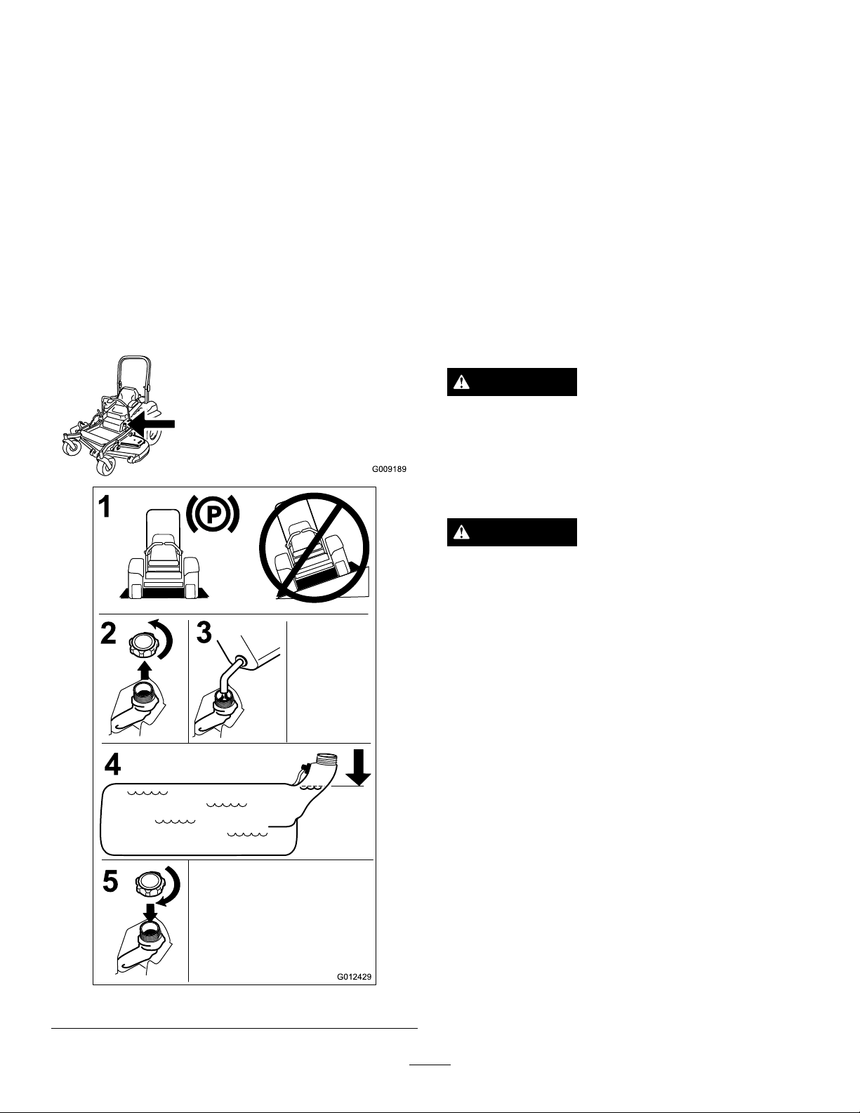
Note:Afuelstabilizer/conditionerismosteffective
G009189
G012429
1
2
4
3
5
whenmixedwithfreshgasoline.T ominimizethe
chanceofvarnishdepositsinthefuelsystem,usefuel
stabilizeratalltimes.
FillingtheFuelTank
CheckingtheEngineOilLevel
Beforeyoustarttheengineandusethemachine,check
theoillevelintheenginecrankcase;refertoChecking
theEngineOilLevel.
Note:Donotllthefueltankcompletelyfull.Fillthe
fueltanktothebottomofthellerneck.Theempty
spaceinthetankallowsthegasolinetoexpand.
1.Parkthemachineonlevelground.
2.Shuttheengineoffandsettheparkingbrake.
3.Cleanaroundthefueltankcap.
4.Fillthefueltanktothebottomofthellerneck.
Ensurethereisemptyspaceinthetanktoallowthe
gasolinetoexpand(Figure7).
BreakingInaNewMachine
Newenginestaketimetodevelopfullpower.Mower
decksanddrivesystemshavehigherfrictionwhennew,
placingadditionalloadontheengine.Allow40to50
hoursofbreak-intimefornewmachinestodevelopfull
powerandbestperformance.
UsingtheRolloverProtection
System(ROPS)
WARNING
Toavoidinjuryordeathfromrollover:keepthe
rollbarintheraisedlockedpositionandusethe
seatbelt.
Ensuretheseatissecuredtothemachine.
WARNING
Thereisnorolloverprotectionwhentherollbar
isinthedownposition.
Figure7
•Lowertherollbaronlywhenabsolutely
necessary.
•Donotweartheseatbeltwhentherollbaris
inthedownposition.
•Driveslowlyandcarefully.
•Raisetherollbarassoonasclearancepermits.
•Checkcarefullyforoverheadclearances(i.e.
branches,doorways,electricalwires)before
drivingunderanyobjectsanddonotcontact
them.
Important:Lowertherollbaronlywhen
absolutelynecessary.
Important:Ensuretheseatissecuredtothe
machine.
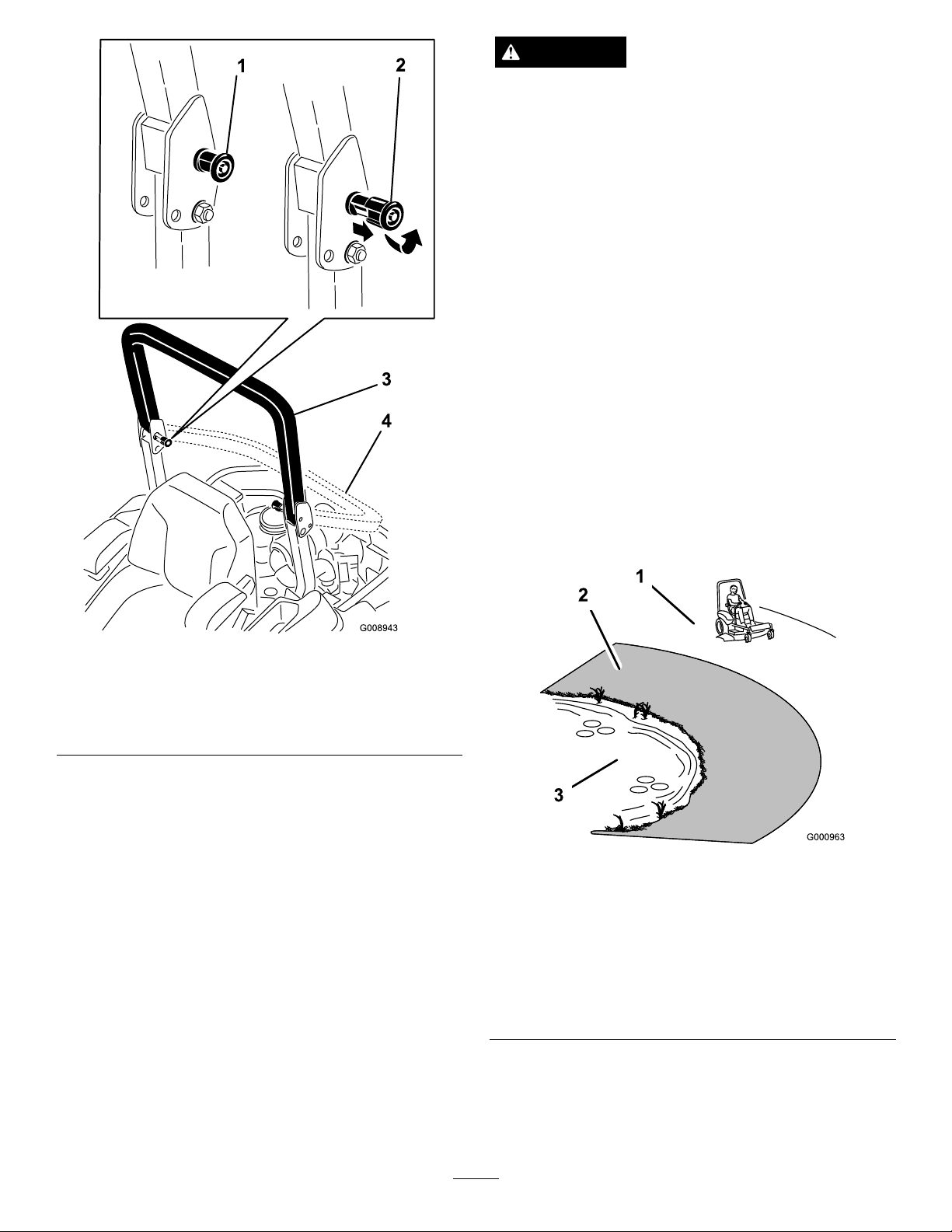
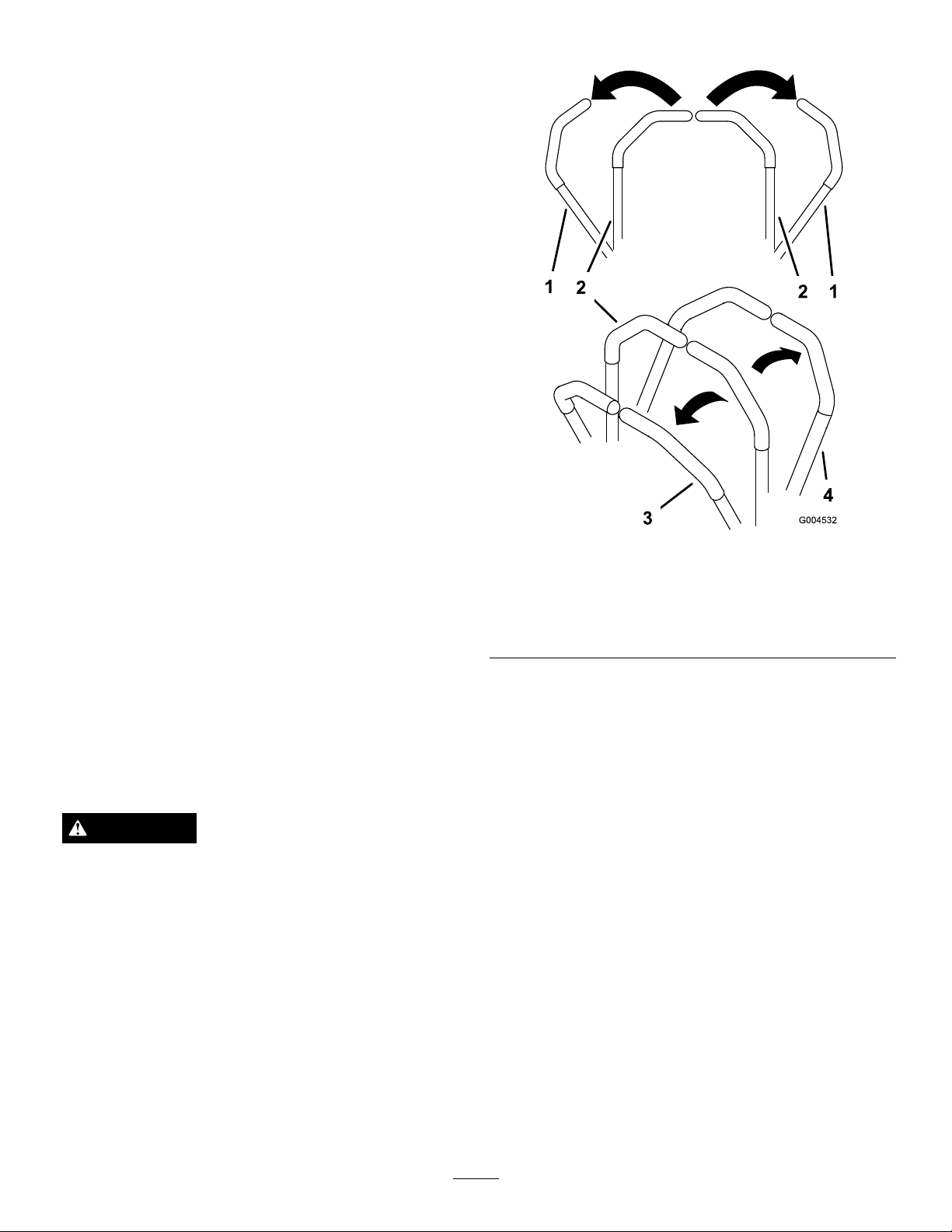
1.Tolowertherollbar,applyforwardpressuretothe
upperpartoftherollbar.
2.Pullbothknobsoutandrotatethem90°sotheyare
notengaged(Figure8).
3.Lowertherollbartothedownposition(Figure8).
15
Page 16
DANGER
Operatingonwetgrassorsteepslopescancause
slidingandlossofcontrol.
Wheelsdroppingoveredgescancauserollovers,
whichmayresultinseriousinjury,deathor
drowning.
Thereisnorolloverprotectionwhentherollbar
isdown.
Alwayskeeptherollbarintheraisedandlocked
positionandusetheseatbelt.
Readandfollowtherolloverprotectioninstructions
andwarnings.
Toavoidlossofcontrolandpossibilityofrollover:
•Donotoperateneardrop-offsornearwater.
•Donotoperateonslopesgreaterthan
15degrees.
•Reducespeedanduseextremecautionon
slopes.
Figure8
1.ROPSknob
2.PullROPSknoboutand
rotate90degrees
3.Rollbarintheupright
position
4.Rollbarinthefolded
position
4.Toraisetherollbar,raisetherollbartotheoperate
position,rotatetheknobssotheymovepartially
intothegrooves(Figure8).
5.Raisetherollbartothefulluprightpositionwhile
pushingontheupperrollbarandthepinswillsnap
intopositionwhentheholesalignwiththepins
Figure8).Pushontherollbarandensurethat
(
bothpinsareengaged.
Important:Alwaysusetheseatbeltwiththe
rollbarintheraisedposition.
•Avoidsuddenturnsorrapidspeedchanges.
Figure9
1.SafeZone-usethe
ZMasterhereonslopes
lessthan15degreesor
atareas.
2.DangerZone-useawalk
behindmowerand/ora
handtrimmeronslopes
greaterthan15degrees,
neardrop-offsandwater.
3.Water
ThinkSafetyFirst
Pleasereadallsafetyinstructionsandsymbolsinthe
safetysection.Knowingthisinformationcouldhelp
youorbystandersavoidinjury.
16
Page 17
CAUTION
G009027
1
2
G008960
1
2
G008944
1
2
3
G008945
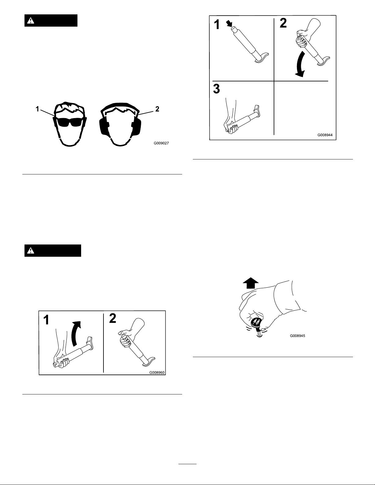
Thismachineproducessoundlevelsinexcessof
85dBAattheoperatorsearandcancausehearing
lossthroughextendedperiodsofexposure.
Wearhearingprotectionwhenoperatingthis
machine.
Theuseofprotectiveequipmentforeyes,ears,feetand
headisrecommended.
Figure10
Figure12
1.Wearsafetyglasses
2.Wearhearingprotection
OperatingtheParkingBrake
Alwayssettheparkingbrakewhenyoustopthe
machineorleaveitunattended.
SettingtheParkingBrake
WARNING
Parkingbrakemaynotholdmachineparkedona
slopeandcouldcausepersonalinjuryorproperty
damage.
Donotparkonslopesunlesswheelsarechocked
orblocked
OperatingtheMowerBlade
ControlSwitch(PTO)
Thebladecontrolswitch(PTO)startsandstopsthe
mowerbladesandanypoweredattachments.
EngagingtheBladeControlSwitch
(PTO)
Note:Engagingthebladecontrolswitch(PTO)with
thethrottlepositionathalforlesswillcauseexcessive
weartothedrivebelts.
Figure13
Figure11
ReleasingtheParkingBrake
Pushinthereleasebuttonbeforepushingdown.
17
Page 18
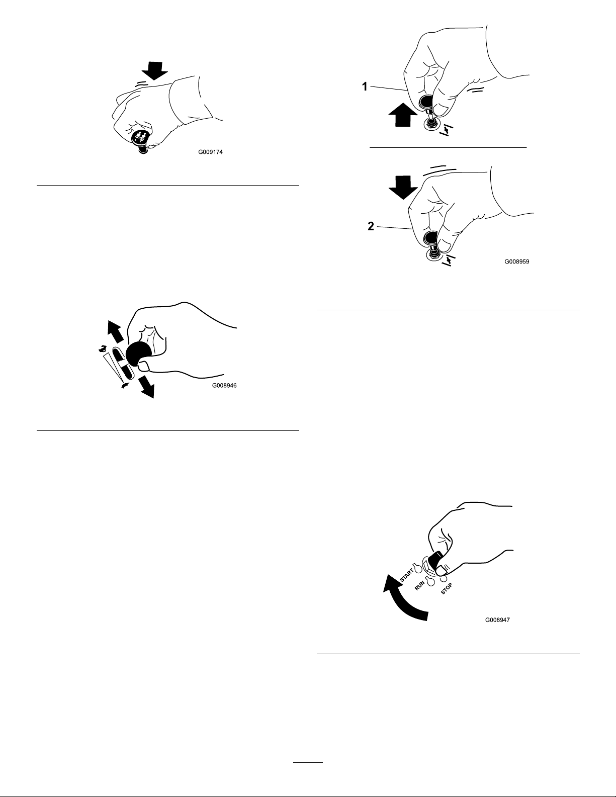
DisengagingtheBladeControlSwitch
G009174
G008946
G008959
1
2
START
RUN
STOP
G008947
(PTO)
Figure14
OperatingtheThrottle
ThethrottlecontrolcanbemovedbetweenFastand
Slowpositions(
Figure15).
Alwaysusethefastpositionwhenturningonthe
mowerdeckwiththebladecontrolswitch(PTO).
Figure15
OperatingtheChoke
Usethechoketostartacoldengine.
1.Iftheengineiscold,usethechoketostartthe
engine.
2.Pulluponthechokeknobtoengagethechoke
beforeusingtheignitionswitch(
Figure16).
Figure16
1.On2.Off
OperatingtheIgnitionSwitch
1.TurntheignitionkeytotheStartposition
(Figure17).Whentheenginesstarts,releasethekey.
Important:Donotengagestarterformore
than5secondsatatime.Iftheenginefails
tostartallowa15secondcool-downperiod
betweenattempts.Failuretofollowthese
instructionscanburnoutthestartermotor.
Note:Additionalstartingcyclesmayberequired
whenstartingtheengineforthersttimeafterthe
fuelsystemhasbeenwithoutfuelcompletely.
3.Pushdownonthechoketodisengagethechoke
aftertheenginehasstarted(Figure16).
Figure17
2.Turntheignitionkeytostoptostoptheengine.
UsingtheFuelShut-OffValve
Thefuelshut-offvalveislocatedundertheseat.Move
theseatforwardtoaccessit.
18
Page 19
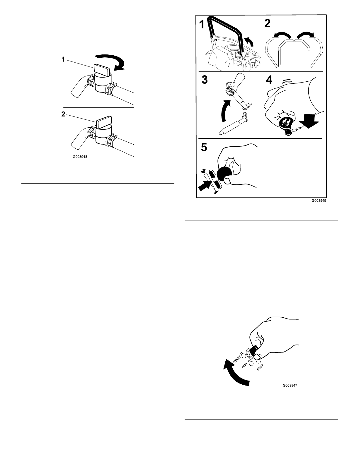
Closethefuelshut-offvalvefortransport,maintenance,
G008948
1
2
START
RUN
STOP
G008947
andstorage.
Ensurethefuelshut-offvalveisopenwhenstarting
theengine.
Figure18
1.On2.Off
StartingandStoppingthe
Figure19
Engine
StartingtheEngine
1.RaisetheROPSupandlockintoplace,sitonthe
seatandfastentheseatbelt.
2.Movethemotioncontrolstoneutrallocked
position.
3.Settheparkingbrake;refertoSettingtheParking
Brake.
4.Movethebladecontrolswitch(PTO)totheOff
position(
5.MovethethrottlelevermidwaybetweentheSlow
andFastpositions.
Figure19).
6.TurntheignitionkeytotheStartposition
Figure17).Whentheenginesstarts,releasethekey.
(
Important:Donotengagestarterformore
than5secondsatatime.Iftheenginefails
tostartallowa15secondcool-downperiod
betweenattempts.Failuretofollowthese
instructionscanburnoutthestartermotor.
Note:Additionalstartingcyclesmayberequired
whenstartingtheengineforthersttimeafterthe
fuelsystemhasbeenwithoutfuelcompletely.
Figure20
1.Off3.Start
2.Run
19
Page 20
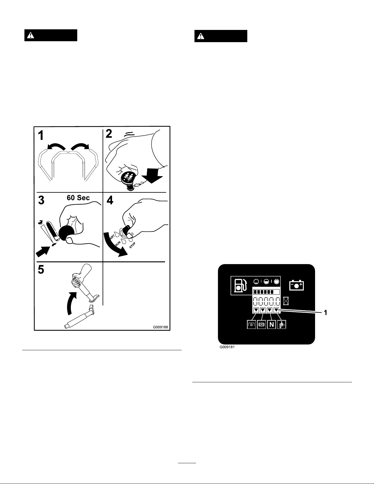
StoppingtheEngine
G009181
1
TheSafetyInterlockSystem
CAUTION
Childrenorbystandersmaybeinjuredifthey
moveorattempttooperatethetractorwhileitis
unattended.
Alwaysremovetheignitionkeyandsettheparking
brakewhenleavingthemachineunattended,even
ifjustforafewminutes.
Lettheengineidleatslowthrottle(turtle)for60
secondsbeforeturningtheignitionswitchoff.
CAUTION
Ifsafetyinterlockswitchesaredisconnectedor
damagedthemachinecouldoperateunexpectedly
causingpersonalinjury.
•Donottamperwiththeinterlockswitches.
•Checktheoperationoftheinterlockswitches
dailyandreplaceanydamagedswitchesbefore
operatingthemachine.
UnderstandingtheSafetyInterlock
System
Thesafetyinterlocksystemisdesignedtopreventthe
enginefromstartingunless:
•Theparkingbrakeisengaged.
•Thebladecontrolswitch(PTO)isdisengaged.
•Themotioncontrolleversareintheneutrallocked
position
Thesafetyinterlocksystemalsoisdesignedtostopthe
enginewhenthetractioncontrolsaremovedfromthe
lockedpositionwiththeparkingbrakeengagedorif
yourisefromtheseatwhenthePTOisengaged.
Figure21
Important:Makesurethatthefuelshutoffvalveis
closedbeforetransportingorstoringthemachine,
asfuelleakagemayoccur.Settheparkingbrake
beforetransporting.Makesuretoremovethekey
asthefuelpumpmayrunandcausethebattery
tolosecharge.
Thehourmeterhassymbolstonotifytheuserwhenthe
interlockcomponentisinthecorrectposition.When
thecomponentisinthecorrectposition,atrianglewill
lightupinthecorrespondingsquare.
Figure22
1.Triangleslightupwhentheinterlockcomponentsareinthe
correctposition
TestingtheSafetyInterlockSystem
ServiceInterval:Beforeeachuseordaily
Testthesafetyinterlocksystembeforeyouusethe
machineeachtime.Ifthesafetysystemdoesnot
operateasdescribedbelow,haveanAuthorizedService
Dealerrepairthesafetysystemimmediately .
20
Page 21
1.Sittingontheseat,engagetheparkingbrakeand
movethebladecontrolswitch(PTO)toon.Try
startingtheengine;theengineshouldnotcrank.
2.Sittingontheseat,engagetheparkingbrakeand
movethebladecontrolswitch(PTO)tooff.Move
eithermotioncontrollever(outofneutrallocked
position).Trystartingtheengine;theengineshould
notcrank.Repeatforothercontrollever.
3.Sittingontheseat,engagetheparkingbrake,move
thebladecontrolswitch(PTO)tooffandmove
themotioncontrolleverstoneutrallockposition.
Nowstarttheengine.Whiletheengineisrunning,
releasetheparkingbrake,engagethebladecontrol
switch(PTO)andriseslightlyfromtheseat;the
engineshouldstop.
4.Sittingontheseat,engagetheparkingbrake,move
thebladecontrolswitch(PTO)tooffandmove
themotioncontrolleverstoneutrallockposition.
Nowstarttheengine.Whiletheengineisrunning,
centereithermotioncontrolandmove(forwardor
reverse);theengineshouldstop.Repeatforother
motioncontrol.
UsingtheMotionControlLevers
5.Sittingontheseat,disengagetheparkingbrake,
movethebladecontrolswitch(PTO)tooffand
movethemotioncontrolleverstoneutrallock
position.Trystartingtheengine;theengineshould
notcrank.
DrivingForwardorBackward
Thethrottlecontrolregulatestheenginespeedas
measuredinrpm(revolutionsperminute).Place
thethrottlecontrolinthefastpositionforbest
performance.Alwaysoperateinthefullthrottle
positionwhenmowing.
CAUTION
Machinecanspinveryrapidly.Operatormaylose
controlofmachineandcausepersonalinjuryor
damagetomachine.
•Usecautionwhenmakingturns.
•Slowthemachinedownbeforemakingsharp
turns.
Figure23
1.Motioncontrol
lever-neutrallockposition
2.Center,unlockedposition5.Frontofmachine
3.Forward
4.Backward
DrivingForward
Note:Theenginewillkillifthetractioncontrollevers
aremovedwiththeparkingbrakeengaged.
Tostop,pullthemotioncontrolleverstotheneutral
position.
1.Releasetheparkingbrake;refertoReleasingthe
ParkingBrakeinOperation.
2.Movetheleverstothecenter,unlockedposition.
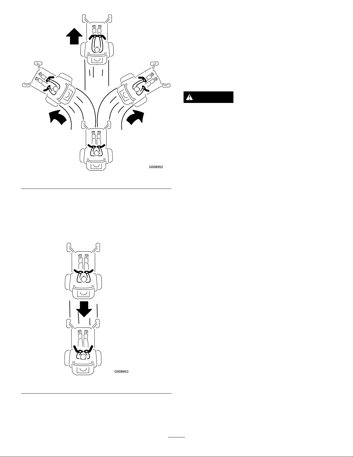
3.Togoforward,slowlypushthemotioncontrol
leversforward(
Figure24).
21
Page 22
G008952
G008953
StoppingtheMachine
Tostopthemachine,movethetractioncontrollevers
toneutralandmovetolockedposition,disengagethe
powertakeoff(bladecontrolswitch(PTO),andturn
theignitionkeytooff.
Settheparkingbrakewhenyouleavethemachine;refer
toSettingtheParkingBrakeinOperation.Remember
toremovethekeyfromtheignitionswitch.
CAUTION
Childrenorbystandersmaybeinjuredifthey
moveorattempttooperatethetractorwhileitis
unattended.
Alwaysremovetheignitionkeyandsettheparking
brakewhenleavingthemachineunattended,even
ifjustforafewminutes.
Figure24
DrivingBackward
1.Movetheleverstothecenter,unlockedposition.
2.Togobackward,slowlypullthemotioncontrol
leversrearward(Figure25).
AdjustingtheHeightofCut
UsingtheTransportLock
Thetransportlockhastwopositionsandisusedwith
thedeckliftpedal.Thereisalockpositionandaunlock
positionforthetransportposition.Thetransportlock
isusedwiththedeckliftpedal.Referto
Figure26
Figure25
22
Page 23
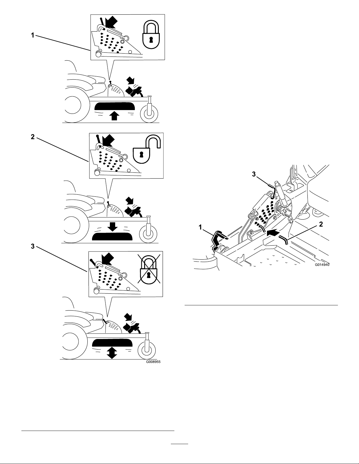
AdjustingtheHeight-of-CutPin
G014940
Theheight-of-cutisadjustedfrom1-1/2to4-1/2inches
(38to114mm)in1/4inch(6mm)incrementsby
relocatingtheclevispinintodifferentholelocations.
1.Movethetransportlocktothelockposition.
2.Pushonthedeckliftpedalwithyourfootandraise
themowerdecktothetransportposition(also
the4-1/2inch(114mm)cuttingheightposition)
Figure27).
(
3.Toadjust,rotatethepin90degreesandremovethe
pinfromtheheight-of-cutbracket(
4.Selectaholeintheheight-of-cutbracket
correspondingtotheheight-of-cutdesiredand,
insertthepin(Figure27).
5.Pushonthedecklift,pullbackonthetransport
lock,andslowlylowerthemowerdeck.
Figure27).
Figure26
TransportLockPositions
1.Transportlock3.Unlockposition—doesnot
lockthemowerdeckinto
transportposition
2.Lockposition—mower
deckwilllockintotransport
position
Figure27
1.Deckliftpedal
2.Cutofheightpin
3.Transportlock
AdjustingtheAnti-Scalp
Rollers
Wheneveryouchangetheheight-of-cut,itis
recommendedtoadjusttheheightoftheanti-scalp
rollers.
1.Disengagethebladecontrolswitch(PTO),move
themotioncontrolleverstotheneutrallocked
positionandsettheparkingbrake.
2.Stoptheengine,removethekey,andwaitforall
movingpartstostopbeforeleavingtheoperating
position.
23
Page 24
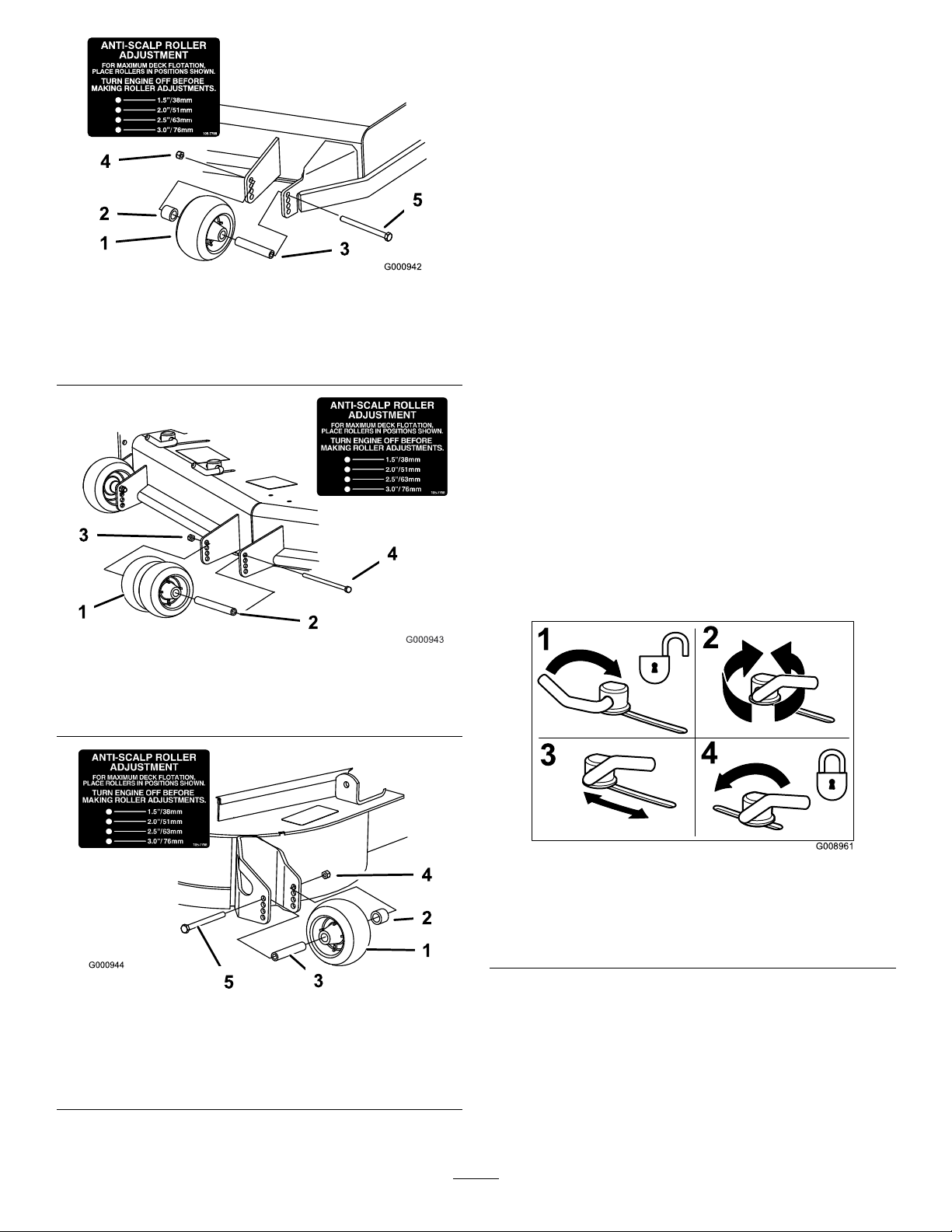
Figure28
G008961
1
2
3
4
1.Anti-scalproller4.FlangeNut
2.Spacer
3.Bushing
5.Bolt
AdjustingtheFlowBafeCam
Locks
Thisprocedureisapplicableonlytomachineswith
theowbafelocks.Certainmodelswillhavenuts
andboltsin-placeoftheowbafelocksandcanbe
adjustedthesame.
Themowerdischargeowcanbeadjustedfordifferent
typesofmowingconditions.Positionthecamlocksand
bafetogivethebestqualityofcut.
1.Disengagethebladecontrolswitch(PTO),move
themotioncontrolleverstotheneutrallocked
positionandsettheparkingbrake.
2.Stoptheengine,removethekey,andwaitforall
movingpartstostopbeforeleavingtheoperating
position.
3.Toadjustthecamlocks,swingtheleverupto
loosenthecamlock(
4.Adjustthebafeandcamlocksintheslotstothe
desireddischargeow .
5.Swingtheleverbackovertotightenthebafeand
camlocks(Figure31).
6.Ifthecamlocksdonotlockthebafeintoplace
oritistootight,loosentheleverandthenrotate
thecamlock.Adjustthecamlockuntilthedesired
lockingpressureisachieved.
Figure31).
Figure29
1.Anti-scalproller3.FlangeNut
2.Bushing4.Bolt
Figure30
1.Anti-scalproller4.FlangeNut
2.Spacer
3.Bushing
5.Bolt
Figure31
1.Unlocklever
2.Rotatethecamlockto
increaseordecrease
lockingpressure
3.Positionthebafe
4.Locklever
PositioningtheFlowBafe
Thefollowingguresareonlyrecommendationsfor
use.Adjustmentswillvarybygrasstype,moisture
content,andheightofgrass.
Note:Iftheenginepowerdrawsdownandthemower
groundspeedisthesame,openupthebafe.
24
Page 25
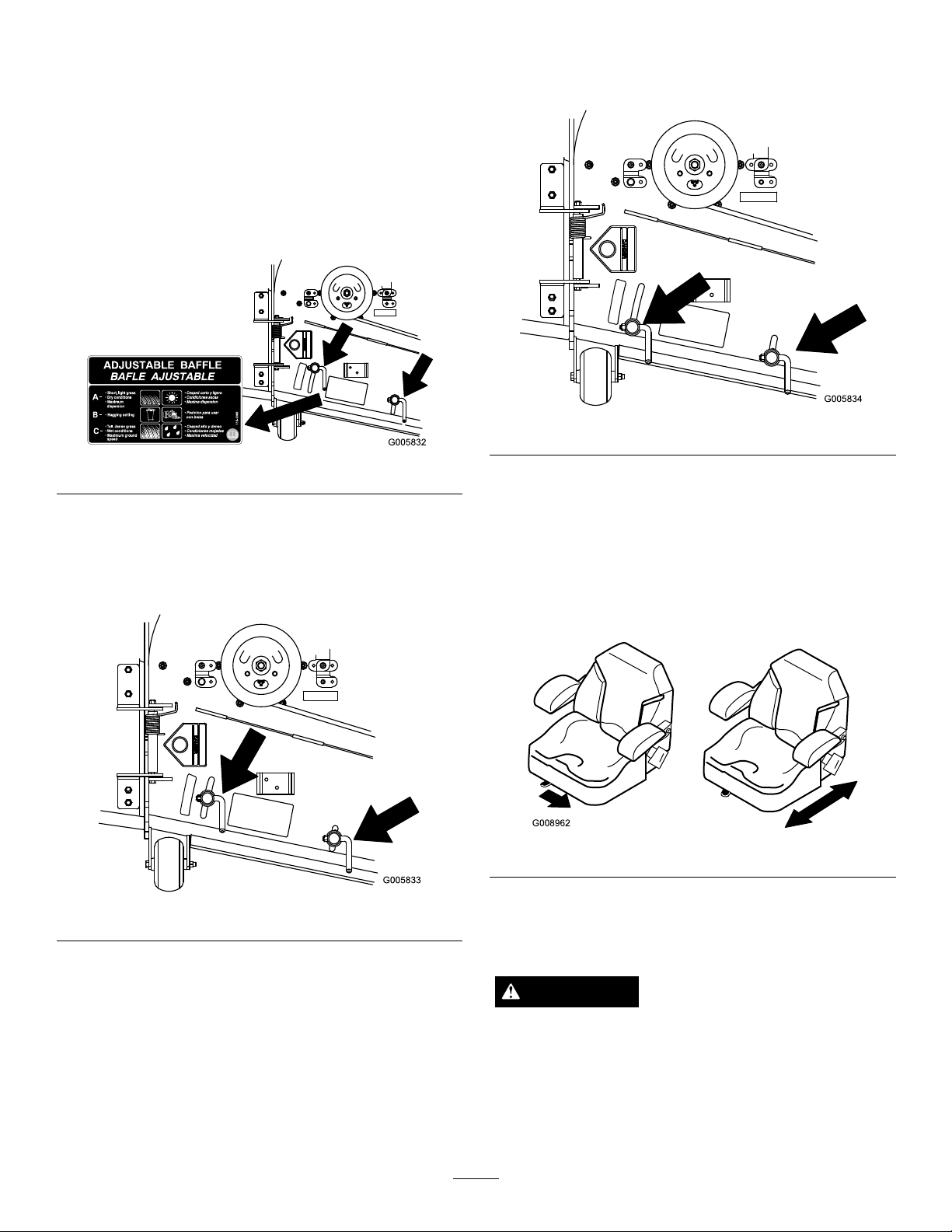
PositionA
G008962
Thisisthefullrearposition.Thesuggesteduseforthis
positionisafollows.
•Useforshort,lightgrassmowingconditions.
•Useindryconditions.
•Forsmallergrassclippings.
•Propelsgrassclippingsfartherawayfromthe
mower.
Figure32
•Allowsincreasedgroundspeedinheavyconditions.
•ThispositionissimilartothebenetsoftheT oro
SFSmower.
Figure34
PositionB
Usethispositionwhenbagging.Alwaysalignitwith
thebloweropening.
Figure33
PositioningtheSeat
Theseatcanmoveforwardandbackward.Positionthe
seatwhereyouhavethebestcontrolofthemachine
andaremostcomfortable.
Toadjust,movetheleversidewaystounlockseat
(Figure35).
Figure35
UsingtheDriveWheelRelease
PositionC
Thisisthefullopenposition.Thesuggestedusefor
thispositionisasfollows.
•Useintall,densegrassmowingconditions.
•Useinwetconditions.
•Lowerstheenginepowerconsumption.
Valves
WARNING
Handsmaybecomeentangledintherotatingdrive
componentsbelowtheenginedeck,whichcould
resultinseriousinjury.
Stoptheengine,removethekey,andallowall
movingpartstostopbeforeaccessingthedrive
wheelreleasevalves.
25
Page 26
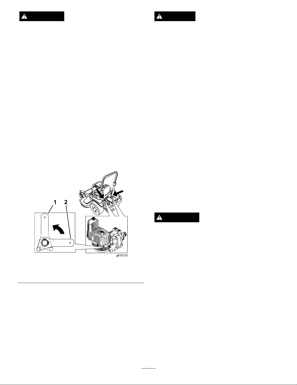
WARNING
g015123
DANGER
Theengineandhydraulicdriveunitscanbecome
veryhot.T ouchingahotengineorhydraulicdrive
unitscancausesevereburns.
Allowtheengineandhydraulicdriveunitstocool
completelybeforeaccessingthedrivewheelrelease
valves.
Thedrivewheelreleasevalvesarelocatedinthebackof
eachhydraulicdriveunit,undertheseat.
Note:Makesurethereleasevalvesareinthefully
horizontalpositionwhenoperatingthemachineor
severedamagetothehydraulicsystemcanoccur.
1.DisengagethePTO(bladecontrolswitch)andturn
theignitionkeytooff.Movetheleverstoneutral
lockedpositionandapplyparkingbrake.Remove
thekey .
2.Rotatethereleasevalveleversverticallytopushthe
machine.Thisallowshydraulicoiltoby-passthe
pumpenablingthewheelstoturn(
Figure36).
3.Disengageparkingbrakebeforepushing.
Withoutagrassdeector,dischargecover,or
completegrasscatcherassemblymountedin
place,youandothersareexposedtobladecontact
andthrowndebris.Contactwithrotatingmower
blade(s)andthrowndebriswillcauseinjuryor
death.
•Neverremovethegrassdeectorfromthe
mowerbecausethegrassdeectorroutes
materialdowntowardtheturf.Ifthe
grassdeectoriseverdamaged,replaceit
immediately.
•Neverputyourhandsorfeetunderthemower.
•Nevertrytoclearthedischargeareaormower
bladesunlessyoumovethepowertakeoff
(bladecontrolswitch(PTO)totheoffposition,
rotatetheignitionkeytooffandremovethekey .
•Makesurethegrassdeectorisinthedown
position.
TransportingMachines
Figure36
1.Verticaltopushthe
machine
2.Horizontaltorunthe
machine
4.Rotatethereleasevalvelevershorizontallytorun
themachine(Figure36).
UsingtheSideDischarge
Themowerhasahingedgrassdeectorthatdisperses
clippingstothesideanddowntowardtheturf.
Useaheavy-dutytrailerortrucktotransportthe
machine.Ensurethatthetrailerortruckhasall
necessarybrakes,lighting,andmarkingasrequiredby
law .Pleasecarefullyreadallthesafetyinstructions.
Knowingthisinformationcouldhelpyou,yourfamily,
petsorbystandersavoidinjury.
WARNING
Drivingonthestreetorroadwaywithoutturn
signals,lights,reectivemarkings,oraslow
movingvehicleemblemisdangerousandcanlead
toaccidentscausingpersonalinjury.
Donotdrivemachineonapublicstreetorroadway.
Totransportthemachine:
1.Ifusingatrailer,connectittothetowingvehicle
andconnectthesafetychains.
2.Ifapplicable,connectthetrailerbrakes.
3.Loadthemachineontothetrailerortruck.
4.Stoptheengine,removethekey,setthebrake,and
closethefuelvalve.
5.Usethemetaltiedownloopsonthemachineto
securelyfastenthemachinetothetrailerortruck
withstraps,chains,cable,orropes(Figure37).
26
Page 27
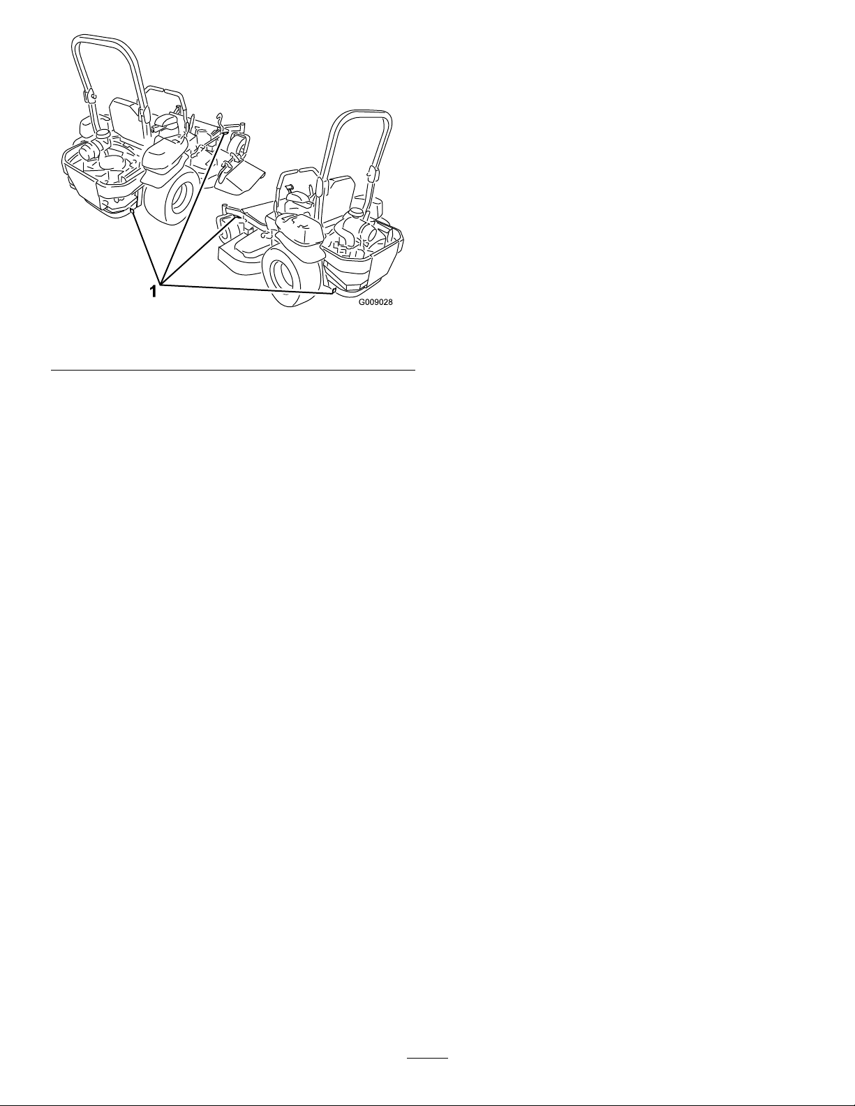
1.Tractionunittiedownloops
Figure37
LoadingMachines
Useextremecautionwhenloadingunitsontrailersor
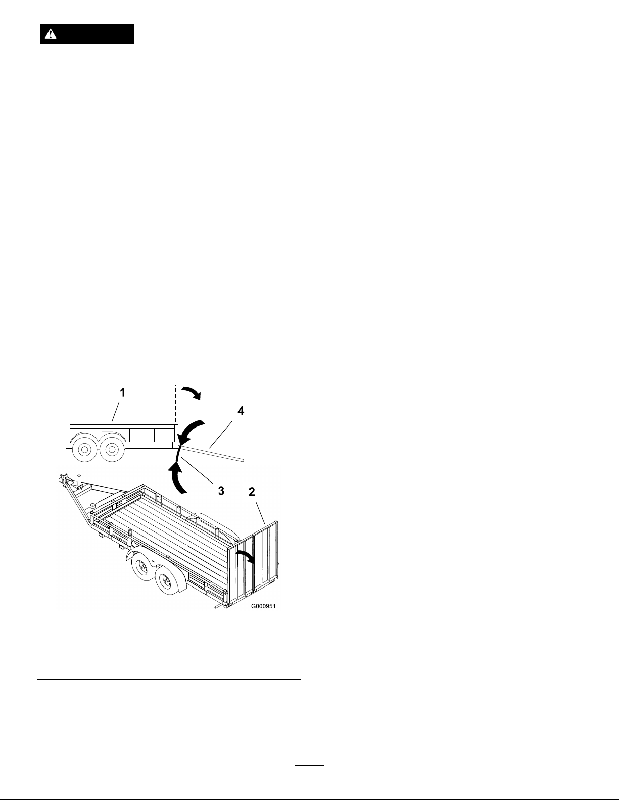
trucks.Onefullwidthrampthatiswideenoughto
extendbeyondthereartiresisrecommendedinsteadof
individualrampsforeachsideoftheunit(Figure38).
Thelowerrearsectionofthetractorframeextendsback
betweentherearwheelsandservesasastopfortipping
backward.Havingafullwidthrampprovidesasurface
fortheframememberstocontactiftheunitstartsto
tipbackward.Ifitisnotpossibletouseonefullwidth
ramp,useenoughindividualrampstosimulateafull
widthcontinuousramp.
Therampshouldbelongenoughsothattheangles
donotexceed15degrees(
maycausemowercomponentstogetcaughtastheunit
movesfromramptotrailerortruck.Steeperangles
mayalsocausetheunittotipbackward.Ifloadingon
ornearaslope,positionthetrailerortrucksoitison
thedownsideoftheslopeandtherampextendsupthe
slope.Thiswillminimizetherampangle.Thetraileror
truckshouldbeaslevelaspossible.
Figure38).Asteeperangle
Important:DoNotattempttoturntheunitwhile
ontheramp;youmaylosecontrolanddriveoff
theside.
Avoidsuddenaccelerationwhendrivinguparampand
suddendecelerationwhenbackingdownaramp.Both
maneuverscancausetheunittotipbackward.
27
Page 28
WARNING
Loadingaunitontoatrailerortruckincreasesthe
possibilityofbackwardtip-overandcouldcause
seriousinjuryordeath.
•Useextremecautionwhenoperatingauniton
aramp.
•EnsuretheROPSisintheuppositionwhile
usingtheseatbeltwhenloadingthemachine.
EnsuretheROPSwillclearthetopofan
enclosedtrailer.
OperatingTips
FastThrottleSetting
Forbestmowingandmaximumaircirculation,operate
theengineatthefastthrottleposition.Airisrequired
tothoroughlycutgrassclippings,sodonotsetthe
height-of-cutsolowastototallysurroundthemower
byuncutgrass.Alwaystrytohaveonesideofthe
mowerfreefromuncutgrass,whichallowsairtobe
drawnintothemower.
•Useonlyasingle,fullwidthramp;DoNotuse
individualrampsforeachsideoftheunit.
•Ifindividualrampsmustbeused,useenough
rampstocreateanunbrokenrampsurface
widerthantheunit.
•Donotexceeda15degreeanglebetweenramp
andgroundorbetweenrampandtraileror
truck.
•Avoidsuddenaccelerationwhiledrivingunitup
aramptoavoidtippingbackward.
•Avoidsuddendecelerationwhilebackingunit
downaramptoavoidtippingbackward.
CuttingaLawnfortheFirstTime
Cutgrassslightlylongerthannormaltoensurethe
cuttingheightofthemowerdoesnotscalpanyuneven
ground.However,thecuttingheightusedinthepastis
generallythebestonetouse.Whencuttinggrasslonger
thansixinchestall,youmaywanttocutthelawntwice
toensureanacceptablequalityofcut.
Cut1/3oftheGrassBlade
Itisbesttocutonlyabout1/3ofthegrassblade.
Cuttingmorethanthatisnotrecommendedunless
grassissparse,oritislatefallwhengrassgrowsmore
slowly.
MowingDirection
Alternatemowingdirectiontokeepthegrassstanding
straight.Thisalsohelpsdisperseclippingswhich
enhancesdecompositionandfertilization.
MowatCorrectIntervals
Figure38
1.Trailer3.Notgreaterthan
15degrees
2.Fullwidthramp4.Fullwidthramp—sideview
Normally,moweveryfourdays.Butremember,
grassgrowsatdifferentratesatdifferenttimes.So
tomaintainthesamecuttingheight,whichisagood
practice,mowmoreofteninearlyspring.Asthegrass
growthrateslowsinmidsummer,mowlessfrequently .
Ifyoucannotmowforanextendedperiod,rstmow
atahighcuttingheight;thenmowagaintwodayslater
atalowerheightsetting.
CuttingSpeed
Toimprovecutquality ,useaslowergroundspeedin
certainconditions.
AvoidCuttingTooLow
Ifthecuttingwidthofthemoweriswiderthanthe
moweryoupreviouslyused,raisethecuttingheightto
ensurethatuneventurfisnotcuttooshort.
28
Page 29

LongGrass
Ifthegrassiseverallowedtogrowslightlylongerthan
normal,orifitcontainsahighdegreeofmoisture,raise
thecuttingheighthigherthanusualandcutthegrassat
thissetting.Thencutthegrassagainusingthelower,
normalsetting.
WhenStopping
Ifthemachine'sforwardmotionmustbestoppedwhile
mowing,aclumpofgrassclippingsmaydropontoyour
lawn.Toavoidthis,moveontoapreviouslycutarea
withthebladesengaged.
KeeptheUndersideoftheMower
Clean
Cleanclippingsanddirtfromtheundersideofthe
moweraftereachuse.Ifgrassanddirtbuildupinside
themower,cuttingqualitywilleventuallybecome
unsatisfactory.
BladeMaintenance
Maintainasharpbladethroughoutthecuttingseason
becauseasharpbladecutscleanlywithouttearingor
shreddingthegrassblades.Tearingandshreddingturns
grassbrownattheedges,whichslowsgrowthand
increasesthechanceofdisease.Checkthecutterblades
dailyforsharpness,andforanywearordamage.File
downanynicksandsharpenthebladesasnecessary.If
abladeisdamagedorworn,replaceitimmediatelywith
agenuineTOROreplacementblade.
29
Page 30

Maintenance
RecommendedMaintenanceSchedule(s)
MaintenanceService
Interval
Aftertherst8hours
Aftertherst100hours
Beforeeachuseordaily
Every50hours
Every100hours
MaintenanceProcedure
•Changetheengineoil.
•Checkthewheelhubslottednuttorque.
•Checkthetorqueforwheellugnuts.
•Checktheparkbrakeadjustment.
•Checkthesafetysystem.
•Checktheengineoillevel.
•Checktheseatbelt.
•Checktherolloverprotectionsystem(ROPS)knobs.
•Cleantheenginescreenandtheoilcooler.
•Checkandcleanthehydraulicunits.
•Checkthemowerblades.
•Cleanthemowerdeck.
•Greasethemowerdeckspindlesandidlerarm.
•Checksparkarrester(ifequipped).
•Checkthetirepressure.
•Inspectthebeltsforcracksandwear.
•Checkthehydraulicoillevel.
•Lubricatethemowerdeckliftpivots.
•Changetheengineoil.(moreoftenindirtyordustyconditions)
•Check,cleanandregapthesparkplug.
•Checkandcleanenginecoolingnsandshrouds.
Every200hours
Every250hours
Every500hours
Monthly
Yearly
Yearlyorbeforestorage
•Lubricatethebrakehandlepivotwithlightoil.
•Changetheengineoillter.
•Replacetheprimaryairlter .
•Checkthesecondaryairlter(22hpand24hpEnginesOnly).
•ChangethehydraulicltersandhydraulicoilwhenusingMobil®1oil.
•Replacethesecondaryairlter(22hpand24hpEnginesOnly).
•Replacethefuellter.(moreoftenindirtyordustyconditions).
•Checkthewheelhubslottednuttorque.
•Checkthetorqueforwheellugnuts.
•Adjustthecasterpivotbearing.
•Checktheparkbrakeadjustment.
•ChangethehydraulicltersandhydraulicoilwhenusingT oro®HYPR-OIL™500
hydraulicoil.
•Checkthebattery .
•Greasethepumpbeltidlerarm.
•Greasethefrontcasterpivots(moreoftenindirtyordustyconditions).
•Repackthefrontcasterwheelbearings(moreoftenindirtyordustyconditions).
•Lubricatethecasterwheelhubs
•Paintchippedsurfaces.
•Checkallmaintenanceprocedureslistedabovebeforestorage.
Important:Refertoyourengineoperator'smanualforadditionalmaintenanceprocedures.
30
Page 31
CAUTION
G014941
Ifyouleavethekeyintheignitionswitch,someonecouldaccidentlystarttheengineandseriouslyinjure
youorotherbystanders.
Removethekeyfromtheignitionbeforeyoudoanymaintenance.
Lubrication
GreasingandLubrication
Greasemorefrequentlywhenoperatingconditionsare
extremelydustyorsandy .
GreaseType:No.2generalpurposelithiumbaseor
molybdenumbasegrease
HowtoGrease
1.Disengagethebladecontrolswitch(PTO),movethe
motioncontrolleverstotheneutrallockedposition
andsettheparkingbrake.
2.Stoptheengine,removethekey,andwaitforall
movingpartstostopbeforeleavingtheoperating
position.
3.Cleanthegreasettingswitharag.Makesureto
scrapeanypaintoffthefrontofthetting(s).
4.Connectagreaseguntothetting.Pumpgrease
intothettingsuntilgreasebeginstooozeoutof
thebearings.
5.Wipeupanyexcessgrease.
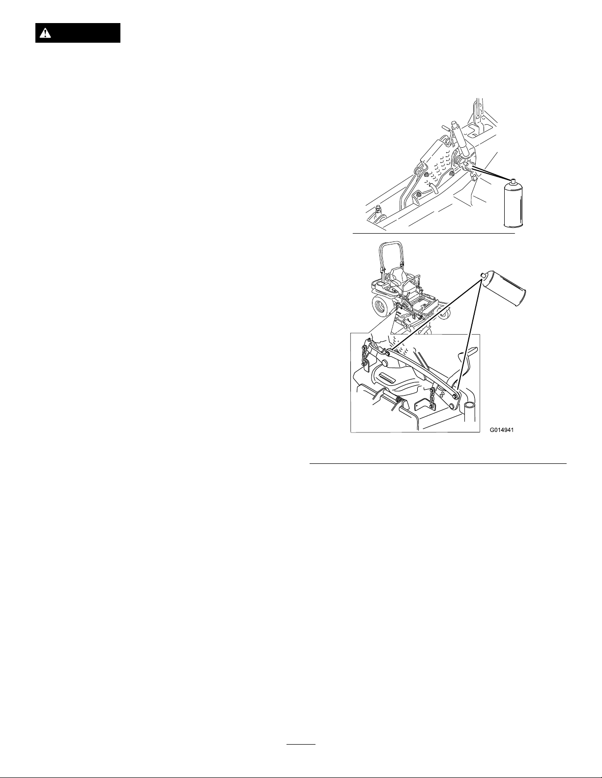
WheretoAddLightOilorSpray
Lubrication
ServiceInterval:Every100hours
Every200hours
•Brakehandlepivot.
•Deckliftpivots.
Figure39
WheretoGreasetheMower
ServiceInterval:Every50hours—Greasethemower
deckspindlesandidlerarm.
Yearly—Greasethepumpbeltidler
arm.
Yearly—Greasethefrontcaster
pivots(moreoftenindirtyordusty
conditions).
Yearly—Repackthefrontcaster
wheelbearings(moreoftenindirtyor
dustyconditions).
Important:Makesurecuttingunitspindlesarefull
ofgreaseweekly.
1.Disengagethebladecontrolswitch(PTO),movethe
motioncontrolleverstotheneutrallockedposition,
andsettheparkingbrake.
31
Page 32
2.Stoptheengine,removethekey,andwaitforall
G009029
g014942
movingpartstostopbeforeleavingtheoperating
position.
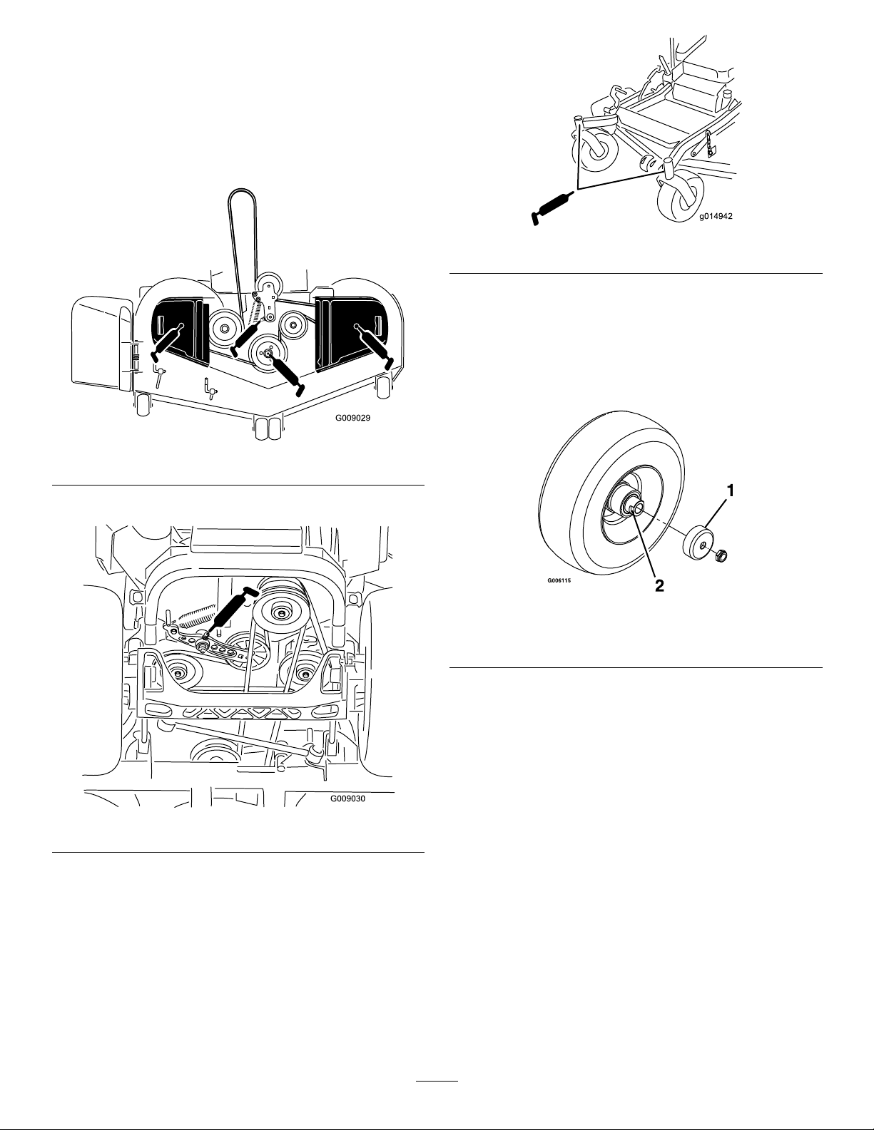
3.Greasethemowerdeckidlerpulleypivotuntilgrease
comeoutthebottom(
Figure40).
4.Greasethethreespindlebearingsuntilgreasecomes
outthelowerseals(Figure40).
Figure40
Figure42
LubricateCasterWheelHubs
ServiceInterval:Yearly
1.Stoptheengine,waitforallmovingpartstostop,
andremovethekey.Engagetheparkingbrake.
5.Greasethedrivebeltidlerarm(Figure41).
Figure41
6.Removethedustcapandadjustthecasterpivots.
Keepthedustcapoffuntilgreasingisdone.Referto
AdjustingtheCasterPivotBearinginMaintenance.
7.Removethehexplug.Threadagreasezerkintothe
hole.
8.Pumpgreaseintothezerkuntilitoozesoutaround
thetopbearing.
9.Removethegreasezerkinthehole.Installthehex
pluganddustcap(Figure42).
Figure43
1.Sealguard2.Spacernutwithwrench
ats
2.Removethecasterwheelfromthecasterforks.
3.Removethesealguardsfromthewheelhub.
4.Removeoneofthespacernutsfromtheaxle
assemblyinthecasterwheel.Notethatthread
lockingadhesivehasbeenappliedtolockthespacer
nutstotheaxle.Removetheaxle(withtheother
spacernutstillassembledtoit)fromthewheel
assembly.
5.Pryoutseals,andinspectbearingsforwearor
damageandreplaceifnecessary.
6.Packthebearingswithageneral-purposegrease.
7.Insertonebearing,onenewsealintothewheel.
Note:Thesealsmustbereplaced.
8.Iftheaxleassemblyhashadbothspacernuts
removed(orbrokenloose),applyathreadlocking
adhesivetoonespacernutandthreadontotheaxle
withthewrenchatsfacingoutward.DoNotthread
32
Page 33

spacernutallofthewayontotheendoftheaxle.
Leaveapproximately1/8inch(3mm)fromtheouter
surfaceofthespacernuttotheendoftheaxleinside
thenut.
9.Inserttheassemblednutandaxleintothewheelon
thesideofthewheelwiththenewsealandbearing.
EngineMaintenance
WARNING
Contactwithhotsurfacesmaycausepersonal
injury.
10.Withtheopenendofthewheelfacingup,ll
theareainsidethewheelaroundtheaxlefullof
general-purposegrease.
11.Insertthesecondbearingandnewsealintothe
wheel.
12.Applyathreadlockingadhesivetothe2ndspacer
nutandthreadontotheaxlewiththewrenchats
facingoutward.
13.Torquethenutto75-80in-lb(8-9N-m),loosen,
thenre-torqueto20-25in-lb(2-3N-m).Makesure
axledoesnotextendbeyondeithernut.
14.Reinstallthesealguardsoverthewheelhuband
insertwheelintocasterfork.Reinstallcasterbolt
andtightennutfully .
Important:Topreventsealandbearingdamage,
checkthebearingadjustmentoften.Spinthecaster
tire.Thetireshouldnotspinfreely(morethan1or
2revolutions)orhaveanysideplay .Ifthewheel
spinsfreely,adjusttorqueonspacernutuntilthere
isaslightamountofdrag.Reapplythreadlocking
adhesive.
Keephands,feet,face,clothingandotherbody
partsawaythemuferandotherhotsurfaces.
ServicingtheAirCleaner
ServiceInterval:Every250hours—Replacethe
primaryairlter.
Every250hours—Checkthe
secondaryairlter(22hpand24hp
EnginesOnly).
Every500hours—Replacethe
secondaryairlter(22hpand24hp
EnginesOnly).
Note:Servicetheaircleanermorefrequentlyif
operatingconditionsareextremelydustyorsandy.
RemovingtheFilters
1.DisengagethePTO ,movethemotioncontrollevers
totheneutrallockedpositionandsettheparking
brake.
2.Stoptheengine,removethekey,andwaitforall
movingpartstostopbeforeleavingtheoperating
position.
3.Pushdowntoreleasetheretainingclampsontheair
cleanerandpulltheaircleanercoveroffoftheair
cleanerbody(
4.Cleantheinsideoftheaircleanercoverwith
compressedair.
5.Gentlyslidetheprimarylteroutoftheaircleaner
Figure44).Avoidknockingthelterintothe
body(
sideofthebody.
6.For22hpand24hpenginesonly,removethe
secondarylteronlyifyouintendtoreplaceit.
Important:Neverattempttocleanthe
secondarylter.Ifthesecondarylterisdirty,
thentheprimarylterisdamagedandyou
shouldreplacebothlters.
7.Inspecttheprimarylterfordamagebylookinginto
thelterwhileshiningabrightlightontheoutside
ofthelter.Holesinthelterwillappearasbright
spots.Ifthelterisdamageddiscardit.
Figure44).
33
Page 34
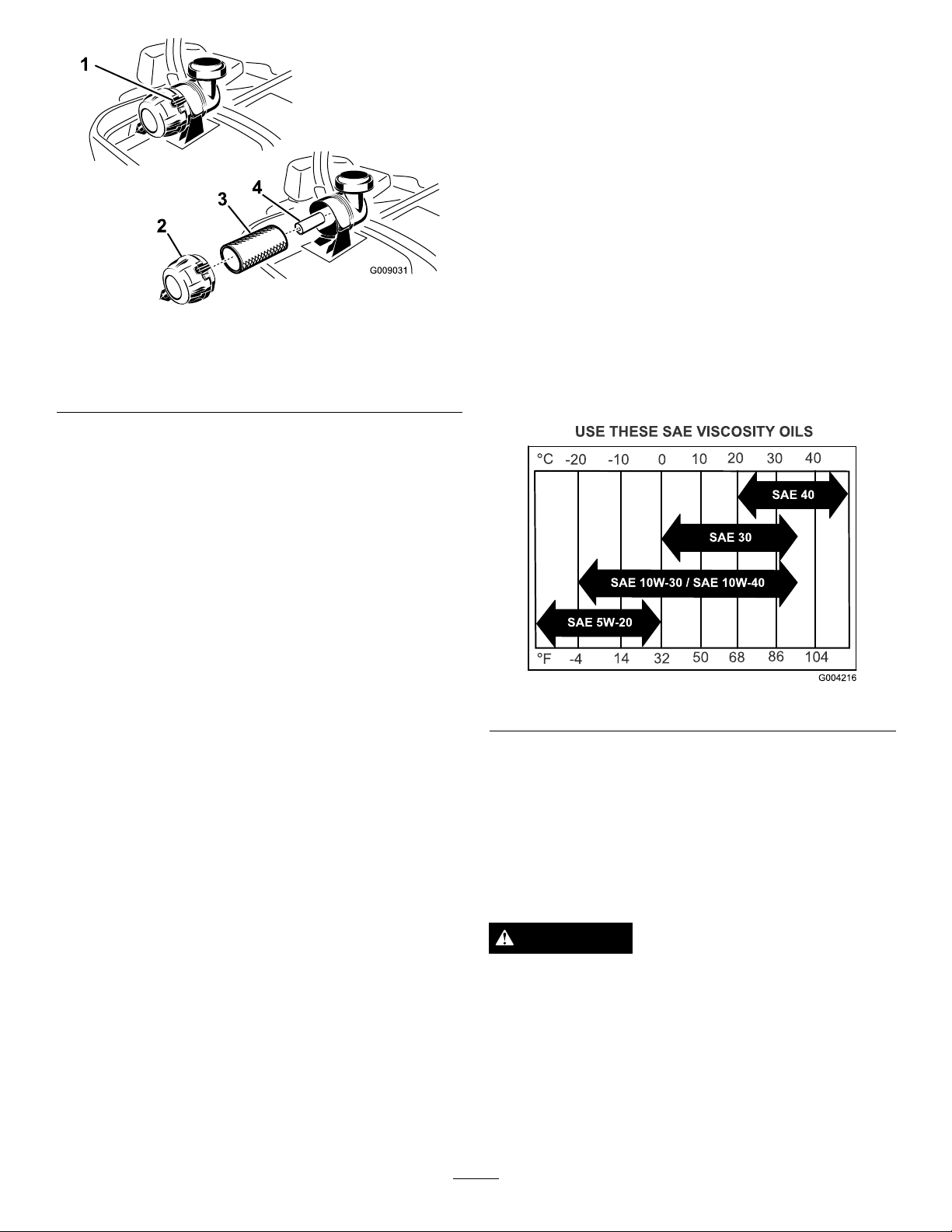
Figure44
1.Aircleanerclamps
2.Aircleanercover
3.Primaryairlter
4.Secondaryairlter(22hp
and24hpEnginesOnly)
ServicingthePrimaryFilter
1.Donotcleanthepaperlter,replaceit(Figure44).
Important:Donotpressonthesoftinsidearea
ofthelter.
4.Installtheaircleanercoverwiththebreathercap
downandrotatesotheretainingclampslockthe
coverinplace(
Figure44).
ServicingtheEngineOil
OilType:Detergentoil(APIserviceSF,SG,SH,SJ,
orSL)
CrankcaseCapacityfor20hpEngines:withalter
change,58ounces(1.7L);withoutalterchange,51
ounces(1.5L)
CrankcaseCapacityfor22hpand24hpEngines:
withalterchange,71ounces(2.1L);withoutalter
change,61ounces(1.8L)
Viscosity:Seethetablebelow .
2.Inspecttheelementfortears,anoilylm,ordamage
totherubberseal.
3.Replacethepaperelementifitisdamaged.
ServicingtheSecondaryFilter(22hp
and24hpEnginesOnly)
Donotcleanthesecondarylter,replaceit.
Important:Neverattempttocleanthesecondary
lter.Ifthesecondarylterisdirty,thenthe
primarylterisdamagedandyoushouldreplace
bothlters.
InstallingtheFilters
Important:Topreventenginedamage,always
operatetheenginewithbothairltersandcover
installed.
1.Ifinstallingnewlters,checkeachlterforshipping
damage.Donotuseadamagedlter.
2.Ifthesecondarylter(22hpand24hpEnginesOnly)
isbeingreplaced,carefullyslideitintothelterbody
(Figure44).
3.Carefullyslidetheprimarylteroverthesecondary
lter(Figure44).Ensurethatitisfullyseatedby
pushingontheouterrimofthelterwhileinstalling
it.
Figure45
Note:Useofmulti-gradeoils(5W -20,10W -30,or
10W-40)willincreaseoilconsumption.Checktheoil
levelmorefrequentlywhenusingthem.
CheckingtheEngineOilLevel
ServiceInterval:Beforeeachuseordaily
Note:Checktheoilwhentheengineiscold.
WARNING
Contactwithhotsurfacesmaycausepersonal
injury.
Keephands,feet,face,clothingandotherbody
partsawayfromthemuferandotherhotsurfaces.
Important:Donotoverllthecrankcasewithoil
becausedamagetotheenginemayresult.Donot
runenginewithoilbelowthelowmarkbecausethe
enginemaybedamaged.
34
Page 35
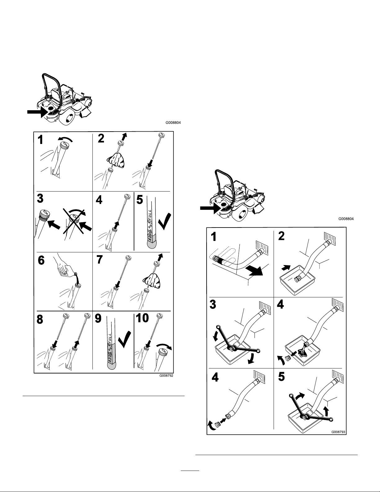
1.DisengagethePTO ,movethemotioncontrollevers
G008804
G008792
1
2
5
6
7
3
9
10
4
8
G008804
G008793
1
2
3
4
4
5
totheneutrallockedpositionandsettheparking
brake.
2.Stoptheengine,removethekey,andwaitforall
movingpartstostopbeforeleavingtheoperating
position(
Figure46).
ChangingtheEngineOil
ServiceInterval:Aftertherst8hours
Every100hours(moreoftenindirty
ordustyconditions)
Note:Disposeoftheusedoilatarecyclingcenter.
1.Starttheengineandletitrunveminutes.This
warmstheoilsoitdrainsbetter.
2.Parkthemachinesothattherearisslightlylower
thanthefronttoensuretheoildrainscompletely.
3.DisengagethePTO ,movethemotioncontrollevers
totheneutrallockedpositionandsettheparking
brake.
4.Stoptheengine,removethekey,andwaitforall
movingpartstostopbeforeleavingtheoperating
position(
Figure47).
Figure46
Figure47
35
Page 36
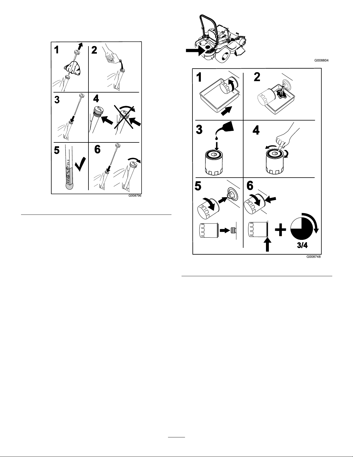
5.Slowlypourapproximately80%ofthespeciedoil
G008796
2
3
4
5
6
1
G008804
G008748
3/4
1
2
3
4
5
6
intothellertubeandslowlyaddtheadditionaloil
tobringittotheFullmark(Figure48).
Figure48
6.Starttheengineanddrivetoaatarea.Checkthe
oillevelagain.
ChangingtheEngineOilFilter
ServiceInterval:Every200hours
Note:Changetheengineoilltermorefrequently
whenoperatingconditionsareextremelydustyorsandy.
1.Draintheoilfromtheengine;refertoChangingthe
EngineOil.
2.Changetheengineoillter(
Figure49).
Figure49
Note:Ensuretheoilltergaskettouchestheengine
andthenanextra3/4turniscompleted.
3.Fillthecrankcasewiththepropertypeofnewoil;
refertoChangingtheOil.
36
Page 37
ServicingtheSparkPlug
g015124
G008794
1
2
ServiceInterval:Every100hours
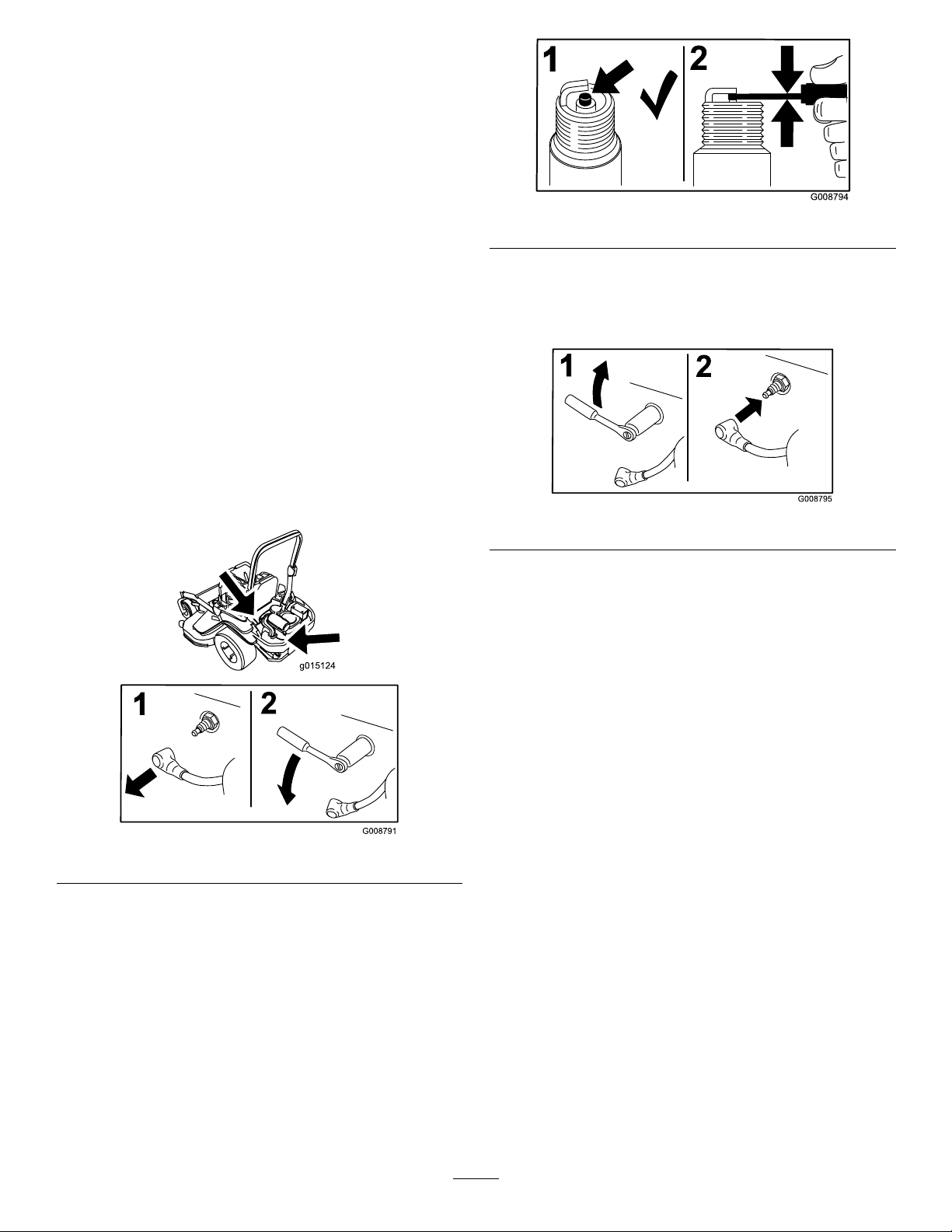
Makesuretheairgapbetweenthecenterandside
electrodesiscorrectbeforeinstallingthesparkplug.
Useasparkplugwrenchforremovingandinstalling
thesparkplug(s)andagappingtool/feelergaugeto
checkandadjusttheairgap.Installanewsparkplug(s)
ifnecessary.
Figure51
TypeofSparkPlug:NGK
AirGap:0.030inch(0.75mm)
®
BPR4ESorequivalent
RemovingtheSparkPlug
1.Stoptheengine,removethekey,andwaitforall
movingpartstostopbeforeleavingtheoperating
position.
2.DisengagethePTO ,movethemotioncontrollevers
totheneutrallockedpositionandsettheparking
brake.
3.Locateandremovethesparkplugs(
Figure50).
InstallingtheSparkPlug
Tightenthesparkplug(s)to16ft.-lb(22N-m).
Figure52
Figure50
CheckingtheSparkPlug
Important:Nevercleanthesparkplug(s).Always
replacethesparkplug(s)whenithas:ablack
coating,wornelectrodes,anoilylm,orcracks.
Ifyouseelightbrownorgrayontheinsulator,the
engineisoperatingproperly .Ablackcoatingonthe
insulatorusuallymeanstheaircleanerisdirty.
Setthegapto0.030inches(0.76mm).
37
Page 38
CheckSparkArrester(if
G008963
12
3
equipped)
ServiceInterval:Every50hours
FuelSystem
Maintenance
WARNING
Hotexhaustsystemcomponentsmayignite
gasolinevaporsevenaftertheengineisstopped.
Hotparticlesexhaustedduringengineoperation
mayigniteammablematerials.Firemayresultin
personalinjuryorpropertydamage.
DoNotrefuelorrunengineunlesssparkarrester
isinstalled.
1.Stopengine,waitforallmovingpartstostop,and
removekey .Engageparkingbrake.
2.Waitformufertocool.
3.Ifanybreaksinthescreenorweldsareobserved,
replacethearrester.
4.Ifpluggingofthescreenisobserved,removethe
arresterandshakelooseparticlesoutofthearrester
andcleanscreenwithawirebrush(soakinsolventif
necessary).Reinstallarresteronexhaustoutlet.
ReplacingtheFuelFilter
ServiceInterval:Every500hours/Yearly(whichever
comesrst)(moreoftenindirtyor
dustyconditions).
Thefuellterislocatedneartheengineonthefront
orrearsideoftheengine.
1.DisengagethePTO ,movethemotioncontrollevers
totheneutrallockedposition,andsettheparking
brake.
2.Stoptheengine,removethekey,andwaitforall
movingpartstostopbeforeleavingtheoperating
position.
3.Allowthemachinetocooldown.
4.Stoptheengine,removethekey,andwaitforall
movingpartstostopbeforeleavingtheoperating
position.
5.Closethefuelshutoffvalveundertheseat
(Figure53).
Figure53
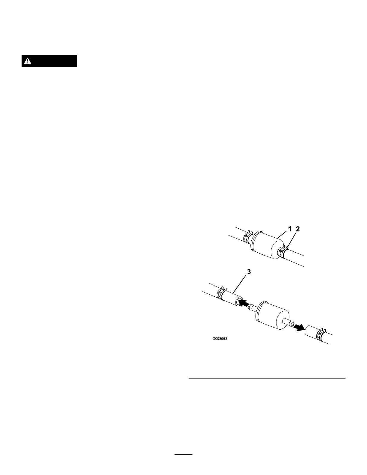
1.Fuellter
2.Hoseclamp
6.Squeezetheendsofthehoseclampstogetherand
slidethemawayfromthelter(Figure53).
7.Removethelterfromthefuellines.
8.Installanewlterandmovethehoseclampsclose
tothelter(
9.Openthefuelshutoffvalve.
38
Figure53).
3.Fuelline
Page 39

Note:Itisimportanttoreinstallthefuellinehosesand
securewithplastictiesthesameastheywereoriginally
installedatthefactorytokeepthefuellineawayfrom
componentsthatcouldcausefuellinedamage.
ElectricalSystem
Maintenance
ServicingtheFuelTank
Donotattempttodrainthefueltank.Ensurethatan
AuthorizedServiceDealerdrainsthefueltankand
servicesanycomponentsofthefuelsystem.
ServicingtheBattery
ServiceInterval:Monthly
WARNING
CALIFORNIA
Proposition65Warning
Batteryposts,terminals,andrelated
accessoriescontainleadandleadcompounds,
chemicalsknowntotheStateofCalifornia
tocausecancerandreproductiveharm.
W ash hands after handling .
DANGER
Batteryelectrolytecontainssulfuricacidwhichisa
deadlypoisonandcausessevereburns.
Donotdrinkelectrolyteandavoidcontactwith
skin,eyesorclothing.Wearsafetyglassestoshield
youreyesandrubberglovestoprotectyourhands.
RemovingtheBattery
WARNING
Batteryterminalsormetaltoolscouldshortagainst
metalmachinecomponentscausingsparks.Sparks
cancausethebatterygassestoexplode,resulting
inpersonalinjury.
•Whenremovingorinstallingthebattery,donot
allowthebatteryterminalstotouchanymetal
partsofthemachine.
•Donotallowmetaltoolstoshortbetween
thebatteryterminalsandmetalpartsofthe
machine.
39
Page 40
WARNING
g014731
+
-
+
-
+
-
1
2
3
4
Incorrectbatterycableroutingcoulddamagethe
machineandcablescausingsparks.Sparkscan
causethebatterygassestoexplode,resultingin
personalinjury.
•AlwaysDisconnectthenegative(black)battery
cablebeforedisconnectingthepositive(red)
cable.
•AlwaysReconnectthepositive(red)battery
cablebeforereconnectingthenegative(black)
cable.
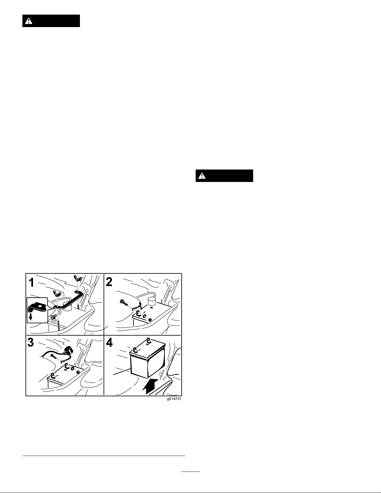
1.Disengagethebladecontrolswitch(PTO),movethe
motioncontrolleverstotheneutrallockedposition
andsettheparkingbrake.
InstallingtheBattery
1.Positionbatteryinthetraywiththeterminalposts
oppositefromthehydraulictank(
2.First,installthepositive(red)batterycableto
positive(+)batteryterminal.
3.Theninstallthenegative(black)batterycableand
groundwiretothenegative(-)batteryterminal.
4.Securethecableswith2bolts,2washers,and
2locknuts(
Figure54).
5.Slidetheredterminalbootontothepositive(red)
batterypost.
6.Installtheclampandsecureitwiththewingnut
Figure54).
(
Figure54).
2.Stoptheengine,removethekey,andwaitforall
movingpartstostopbeforeleavingtheoperating
position.
3.Firstdisconnectthenegativebatterycable(black)
fromthenegative(-)(black)batteryterminal
Figure54).
(
4.Slidetheredterminalbootoffthepositive(red)
batteryterminalandremovethepositive(+)(red)
batterycable(
Figure54).
5.Removethewingnutsecuringthebatteryclamp
(Figure54).
6.Removetheclamp(Figure54).
7.Removethebattery.
ChargingtheBattery
WARNING
Chargingthebatteryproducesgassesthatcan
explode.
Neversmokenearthebatteryandkeepsparksand
amesawayfrombattery.
Important:Alwayskeepthebatteryfullycharged
(1.265specicgravity).Thisisespeciallyimportant
topreventbatterydamagewhenthetemperatureis
below32°F(0°C).
1.Chargebatteryfor10to15minutesat25to30amps
or30minutesat10amps.
2.Whenthebatteryisfullycharged,unplugthecharger
fromtheelectricaloutlet,thendisconnectthe
chargerleadsfromthebatteryposts(
3.Installthebatteryinthemachineandconnectthe
batterycables,refertoInstallingtheBattery.
Figure55).
1.Removethewingnutand
clamp
2.Removethenegative
batterycablebeforethe
positive
Figure54
3.Removethepositive
batterycable
4.Removebattery
Note:Donotrunthemachinewiththebattery
disconnected,electricaldamagemayoccur.
40
Page 41
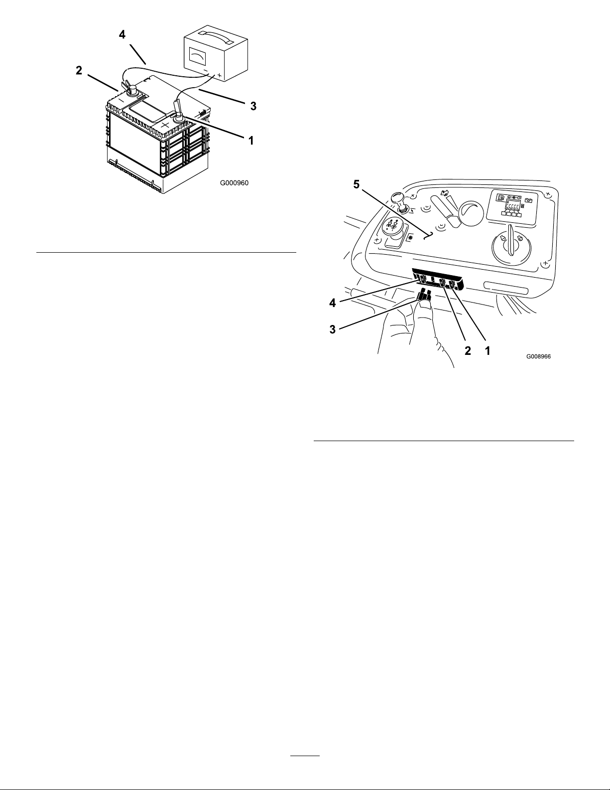
Figure55
ServicingtheFuses
Theelectricalsystemisprotectedbyfuses.Itrequires
nomaintenance,however,ifafuseblowscheckthe
component/circuitforamalfunctionorshort.
1.Thefusesarelocatedonrighthandconsolenextto
theseat(
2.Toreplacethefuses,pulloutonthefusetoremove
it.
3.Installanewfuse(Figure56).
Figure56).
1.PositiveBatteryPost
2.NegativeBatteryPost
3.Red(+)ChargerLead
4.Black(-)ChargerLead
Figure56
1.Optionalaccesory-15amp
2.Charge-25amp5.Console
3.PTO-10amp
4.Main-25amp
41
Page 42
DriveSystem
Maintenance
CheckingtheSeatBelt
ServiceInterval:Beforeeachuseordaily
Visuallyinspectseatbeltforwear,cuts,andproper
operationofretractorandbuckle.Replacebefore
operatingifdamaged.
CheckingtheRollover
ProtectionSystem(ROPS)
Knobs
ServiceInterval:Beforeeachuseordaily
Checkthatboththemountinghardwareandtheknobs
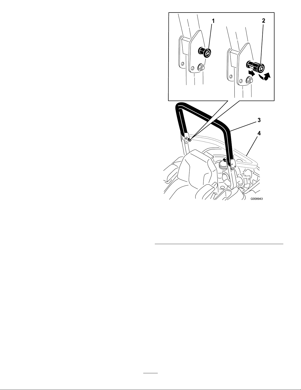
areingoodworkingcondition.Makesuretheknobs
arefullyengagedwiththeROPSintheraisedposition.
Theupperhoopoftherollbarmayneedtobepushed
forwardorpulledrearwardtogetbothknobsfully
engaged.
Figure57
1.ROPSknob(locked
position)
2.PullROPSknoboutand
rotate90degreesto
changerollbarposition
3.Rollbarintheupright
position
4.Rollbarinthefolded
position
AdjustingtheTracking
1.Disengagethebladecontrolswitch(PTO).
2.Drivetoanopenatarea,movethemotioncontrol
leverstotheneutrallockedposition.
3.Movethethrottlemidwaybetweenfastandslow .
4.Movebothmotioncontrolleversallthewayforward
untiltheybothhitthestopsintheT-slot.
5.Checkwhichwaythemachinetracks.
6.Ifittrackstotheright,loosentheboltsandadjust
theleftstopplaterearwardontheleftT-slotuntilthe
machinetracksstraight(Figure58).
42
Page 43
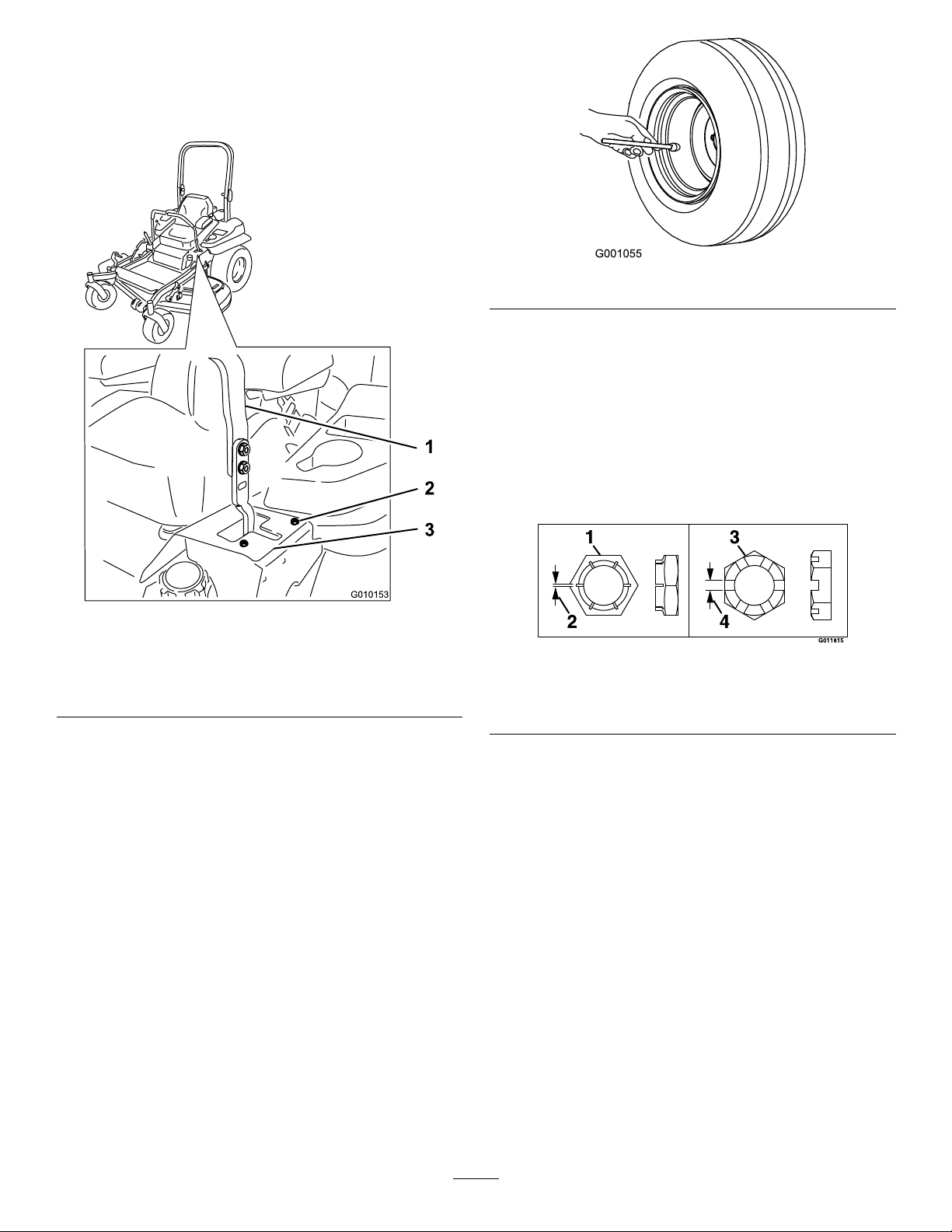
7.Ifittrackstotheleft,loosentheboltsandadjustthe
rightstopplaterearwardontherightT-slotuntilthe
machinetracksstraight(Figure58).
8.Tightenthestopplate(
Figure58).
Figure59
CheckingtheWheelHub
SlottedNut
ServiceInterval:Aftertherst100hours
Every500hours
Figure60todeterminewhichslottednuthasbeen
See
installedontheunit.
Figure58
Leftcontrollevershown
1.Controllever3.Stopplate
2.Bolt
CheckingtheTirePressure
ServiceInterval:Every50hours/Monthly(whichever
comesrst)
Maintaintheairpressureinthefrontandreartiresat
13psi(90kPa).Uneventirepressurecancauseuneven
cut.Checkthetireswhentheyarecoldtogetthemost
accuratepressurereading.
Figure60
1.StyleA(blacknish)3.StyleB(yellowzinc)
2..03inch(.76mm)4..24inch(6mm)
•StyleA(blacknish):
Torquetheslottednutto211-260ft-lb(286-352
N-m).
Note:DoNotuseanti-seizeonwheelhub.
•StyleB(yellowzinc):
1.Removeanddiscardthecotterpin.
2.Torquetheslottednutto200ft-lb(271N-m).
3.Checkdistancefrombottomofslotinnutto
insideedgeofhole.Twothreads(0.1inch)or
lessshouldbeshowing.
43
Page 44
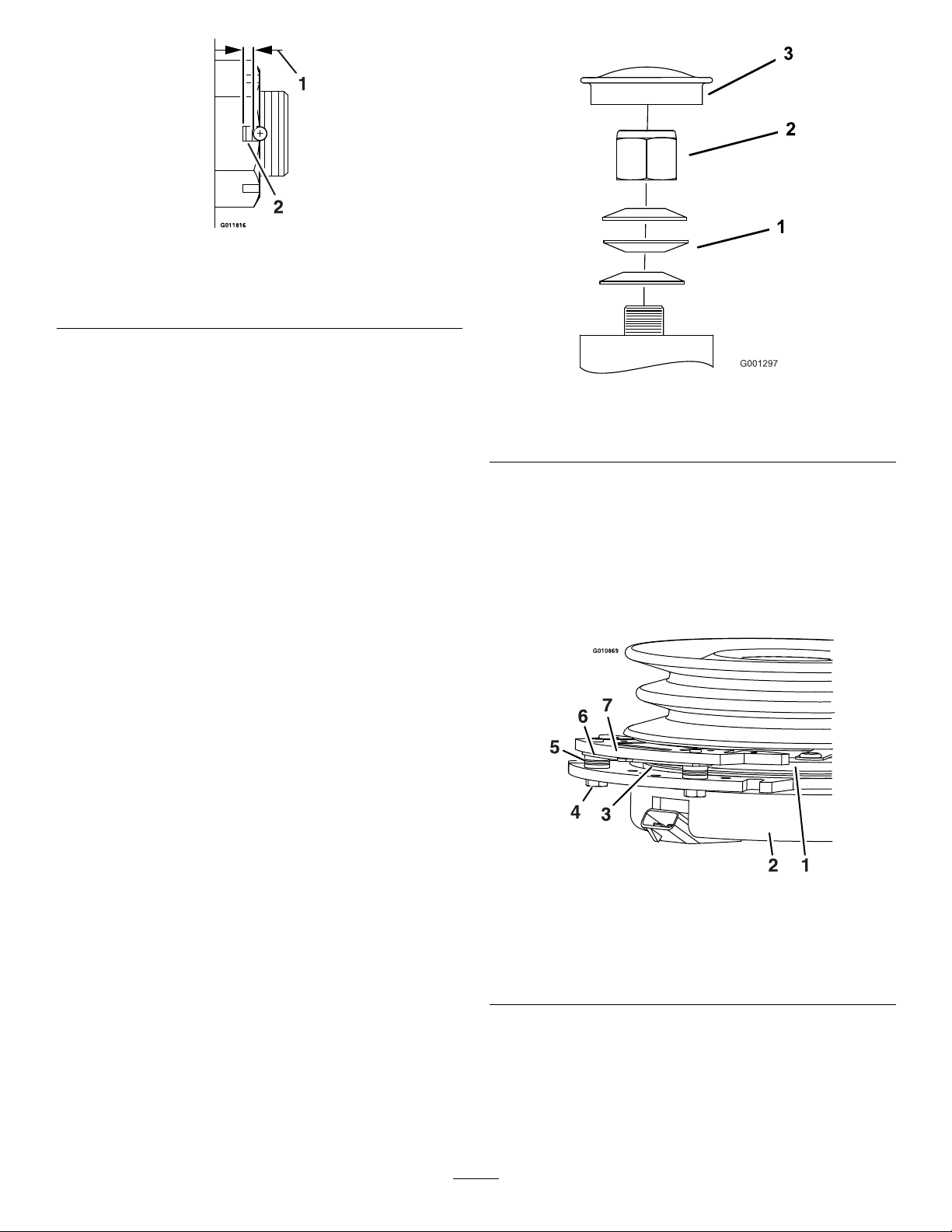
Figure61
1.0.1inchmax2.Nomorethantwothreads
(0.1inchmax)shouldbe
showinghere.
4.Ifmorethantwothreads(0.1inch)areshowing
removenutandinstallwasherbetweenhuband
nut.
5.Torquetheslottednutto200ft-lb(271N-m).
6.Thentightennutuntilthenextsetofslotsline
upwiththecrossholeinshaft.Donotloosen
nuttoaligntheslot.Ifrequired,tightentothe
nextsetofslots.
7.Installanewcotterpin.
Note:DoNotuseanti-seizeonwheelhub.
AdjustingtheCasterPivot
Bearing
ServiceInterval:Every500hours/Yearly(whichever
comesrst)
Figure62
1.SpringWashers3.DustCap
2.LockNut
UsingtheClutchShim
Somelatermodelyearunitshavebeenbuiltwithclutches
thatcontainabrakeshim.Whentheclutchbrakehas
worntothepointwheretheclutchnolongerengages
consistently,theshimcanberemovedtoextendthe
clutchlife.
1.Disengagethebladecontrolswitch(PTO),movethe
motioncontrolleverstotheneutrallockedposition
andsettheparkingbrake.
2.Stoptheengine,removethekey,andwaitforall
movingpartstostopbeforeleavingtheoperating
position.
3.Removethedustcapfromcasterandtightenlock
Figure62).
nut(
4.Tightenthelocknutuntilthespringwashersareat
andthenbackoffa1/4turntoproperlysetthe
pre-loadonthebearings(Figure62).
Important:Makesurethespringwashersare
installedcorrectlyasshowninFigure62.
5.Installthedustcap(Figure62).
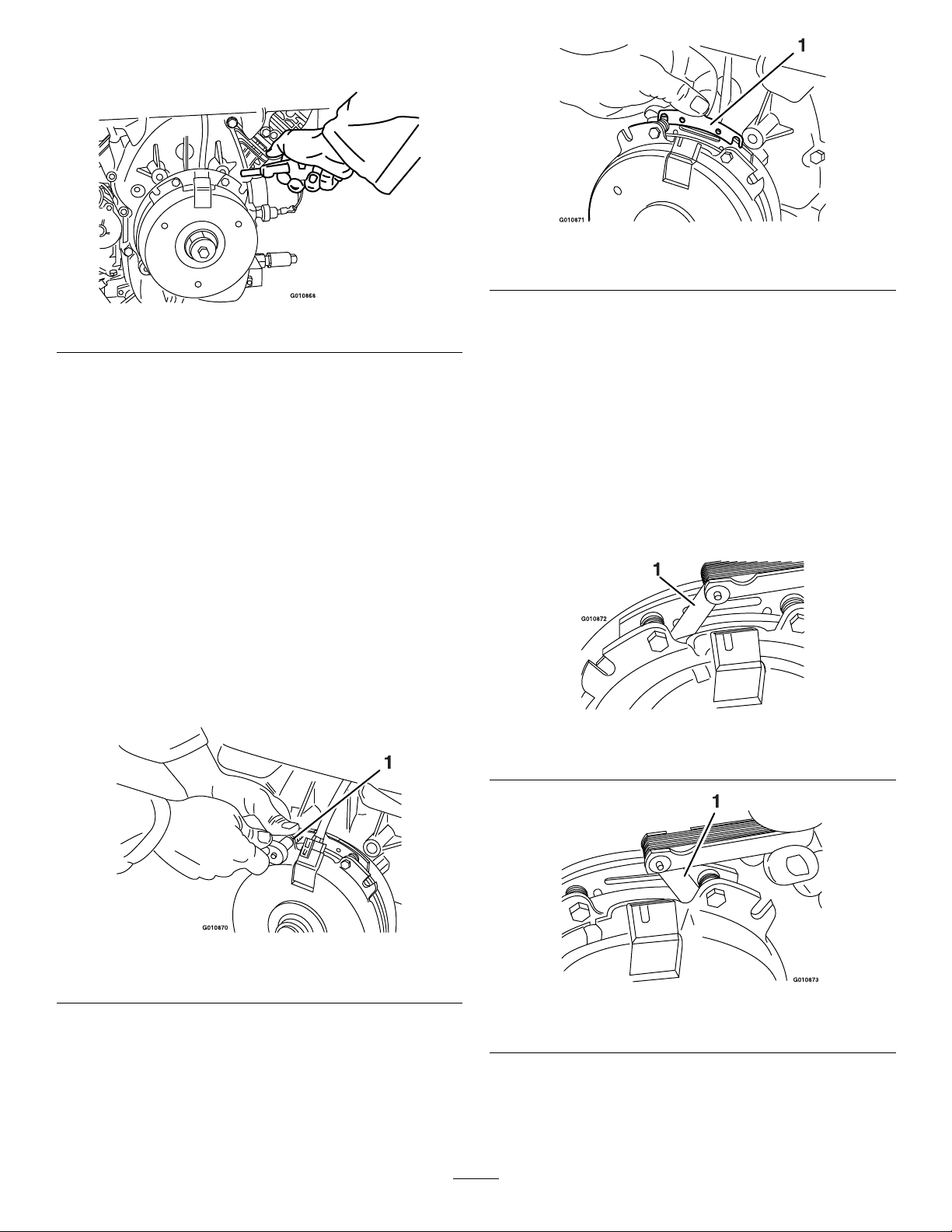
Figure63
1.Armature5.Brakespacer
2.Fieldshell6.Re-gapshim
3.Rotor7.Brakepole
4.Brakemountingbolt
RemovingtheClutchShim
1.Stoptheengine,waitforallmovingpartstostop,
andremovethekey.Engagetheparkingbrake.
Allowthemachinetocoolcompletelybeforestarting
theseinstructions.
44
Page 45
2.Usinganaircompressor,blowoutanydebrisfrom
underthebrakepoleandaroundthebrakespacers.
Figure66
1.Shim
Figure64
3.Checktheconditionofthewireharnessleads,
connectors,andterminals.Cleanorrepairas
necessary.
4.Verifythat12Vispresentattheclutchconnector
whenthePTOswitchisengaged.
5.Measurethegapbetweentherotorandarmature.
Ifthegapisgreaterthan.04inch(1mm),proceed
withthefollowingsteps:
A.Loosenbothbrakemountingboltsone-halfto
onefullturnasshownbelow .
Note:DoNotremovethebrakepolefromthe
eldshell/armature.Thebrakepolehasworn
tomatchthearmatureandneedstocontinueto
matchaftertheshimisremovedtoensureproper
braketorque.
C.Usingapneumaticline,blowoutanydebris
fromunderthebrakepoleandaroundthebrake
spacers.
D.Re-torqueeachbolt(M6x1)to10ft-lb(13N-m)
+/-0.5ft-lb(0.7N-m).
E.Usinga0.010inchthickfeelergauge,verifythat
agapispresentbetweentherotorandarmature
faceonbothsidesofthebrakepoleasshown.
(Duetothewaytherotorandarmaturefaces
wear(peaksandvalleys)itissometimesdifcult
tomeasurethetruegap.)
Figure67
1.Feelergauge
Figure65
1.Brakemountingbolt
B.Usingneedlenosepliers,orbyhand,takehold
ofthetabandremovetheshim(DoNotdiscard
theshimuntilproperclutchfunctionhasbeen
conrmed).
Figure68
1.Feelergauge
45
Page 46
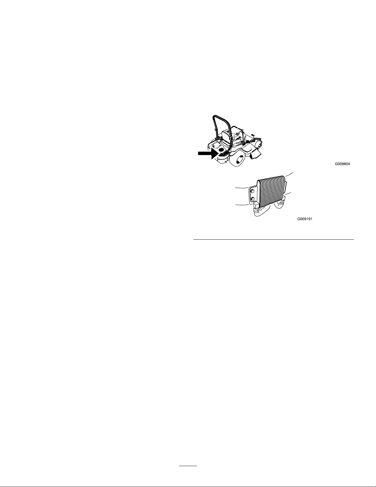
•Ifthegapislessthan0.010inch,thenreinstall
G008804
theshimandreferencetheTroubleshooting
section.
•Ifthegapissufcient,proceedtothesafety
checkinstep
F.Performthefollowingsafetycheck:
a.Sitontheseatandstarttheengine.
b.MakesurethebladesDoNotengagewiththe
PTOswitch“off”andtheclutchdisengaged.
Iftheclutchdoesnotdisengage,reinstallthe
shimandreferencetheTroubleshooting
section.
c.EngageanddisengagethePTOswitch
tenconsecutivetimestoensuretheclutch
isfunctioningproperly.Iftheclutch
doesnotengageproperly ,referencethe
Troubleshootingsection.
F.
CoolingSystem
Maintenance
CleaningtheEngineScreen
andEngineOilCooler
ServiceInterval:Beforeeachuseordaily
Removeanybuild-upofgrass,dirtorotherdebrisfrom
theoilcooler(Figure69).
Figure69
Beforeeachuseremoveanybuild-upofgrass,dirtor
otherdebrisfromtheenginescreen.Thiswillhelp
insureadequatecoolingandcorrectenginespeedand
willreducethepossibilityofoverheatingandmechanical
damagetotheengine(
Figure70).
CleaningtheEngineCooling
FinsandShrouds
ServiceInterval:Every100hours/Yearly(whichever
comesrst)
1.DisengagethePTOandsettheparkingbrake.
2.Stoptheengine,removethekey,andwaitforall
movingpartstostopbeforeleavingtheoperating
position.
3.Removetheairintakescreen,recoilstarterandfan
housing(Figure70).
4.Cleanthedebrisandgrassfromtheengineparts.
5.Installairintakescreen,recoilstarterandfanhousing
(
Figure70).
46
Page 47
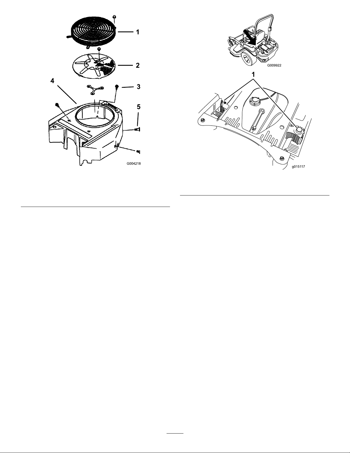
Figure70
g0151 17
1.Engineguard4.Fanhousing
2.Engineairintakescreen
3.Bolt
5.Screw
CheckandCleantheHydraulic
Units
ServiceInterval:Beforeeachuseordaily
1.DisengagethePTOandsettheparkingbrake.
2.Stoptheengine,removethekey,andwaitforall
movingpartstostopbeforeleavingtheoperating
position.
3.Movetheseatforward.
4.Cleanthedebrisandgrassfromthehydraulicunits
Figure71).
(
5.Positiontheseat.
Figure71
1.Hydraulicunits
47
Page 48
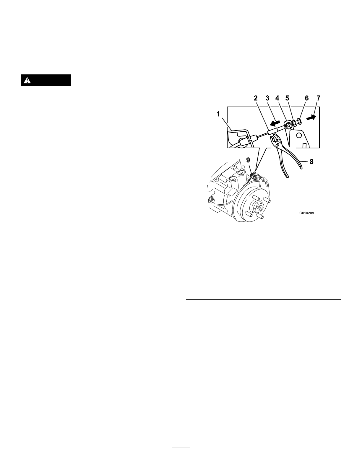
BrakeMaintenance
standardnut.DoNotallowthecabletoturnwhen
thenutsaretightened.
AdjustingtheParkingBrake
ServiceInterval:Aftertherst100hours
Every500hours
DANGER
Mechanicalorhydraulicjacksmayfailtosupport
machineandcauseaseriousinjury .
•Usejackstandwhensupportingmachine.
•Donotusehydraulicjacks.
Checktomakesurethebrakeisadjustedproperly.
1.Drivethemachineontoalevelsurface.
2.Disengagethebladecontrolswitch(PTO),movethe
motioncontrolleverstotheneutrallockedposition
andsettheparkingbrake.
3.Stoptheengine,waitforallthemovingpartstostop,
andremovethekey.
4.Raisethebackofthemachineupandsupportthe
machinewithjackstands.
15.Closethedrivewheelreleasevalve.RefertoUsing
theDriveWheelValvesinOperation.
16.Repeatontheoppositesideofthemachine.
17.Installthereartiresandtorquethelugnutsto90-95
ft-lb(122-129N-m).
18.Removejackstands.
5.Removethereartiresfromthemachine.
6.Removeanydebrisfromthebrakearea.
7.Openthedrivewheelreleasevalves.RefertoUsing
theDriveWheelValvesinOperation.
8.Disengagetheparkingbrake.
9.Usinghandsandngersonly ,pushthecaliperlever
armtoengagethebrakepadsontherotoruntilthe
leverstops(
Figure72).
Notetheorderofthestandardnutandlocknut.
10.Whileholdingtheleveratthestoppedposition,use
theotherhandorngerstopullthecablethreaded
endtightthroughtheswivel.Spinthestandardnut
againsttheswivel(
Figure72).
11.Trytoturnthewheelhubinbothdirectionsrelative
tothecaliper.Thereshouldbeslightmovement
betweenthem;somefriction/resistanceisacceptable.
12.Ifthereisnomovementbetweenthehubrotorand
thecaliperthenbackoffthestandardnutoneturn
fromtheswivelandrepeatstep11
Figure72
LeftHandBrakeShown
1.Cableanchor
2.Threadedrod7.Pullcablethreadedrod
3.Pushleverthisdirection8.Holdthreadedrodhere
4.Caliperleverarm9.Swivel(pivothead)
5.Standardnut(shown
againstswivel)
6.Locknut
thisdirection
13.Ifthehubrotormovesveryfreelyrelativetothe
caliper,thentightenthestandardnutoneturn
againsttheswivelandrepeatstep
11
14.Oncestep11isachieved,holdthethreadedrod
endwithatoolandtightenthelocknutagainstthe
48
Page 49
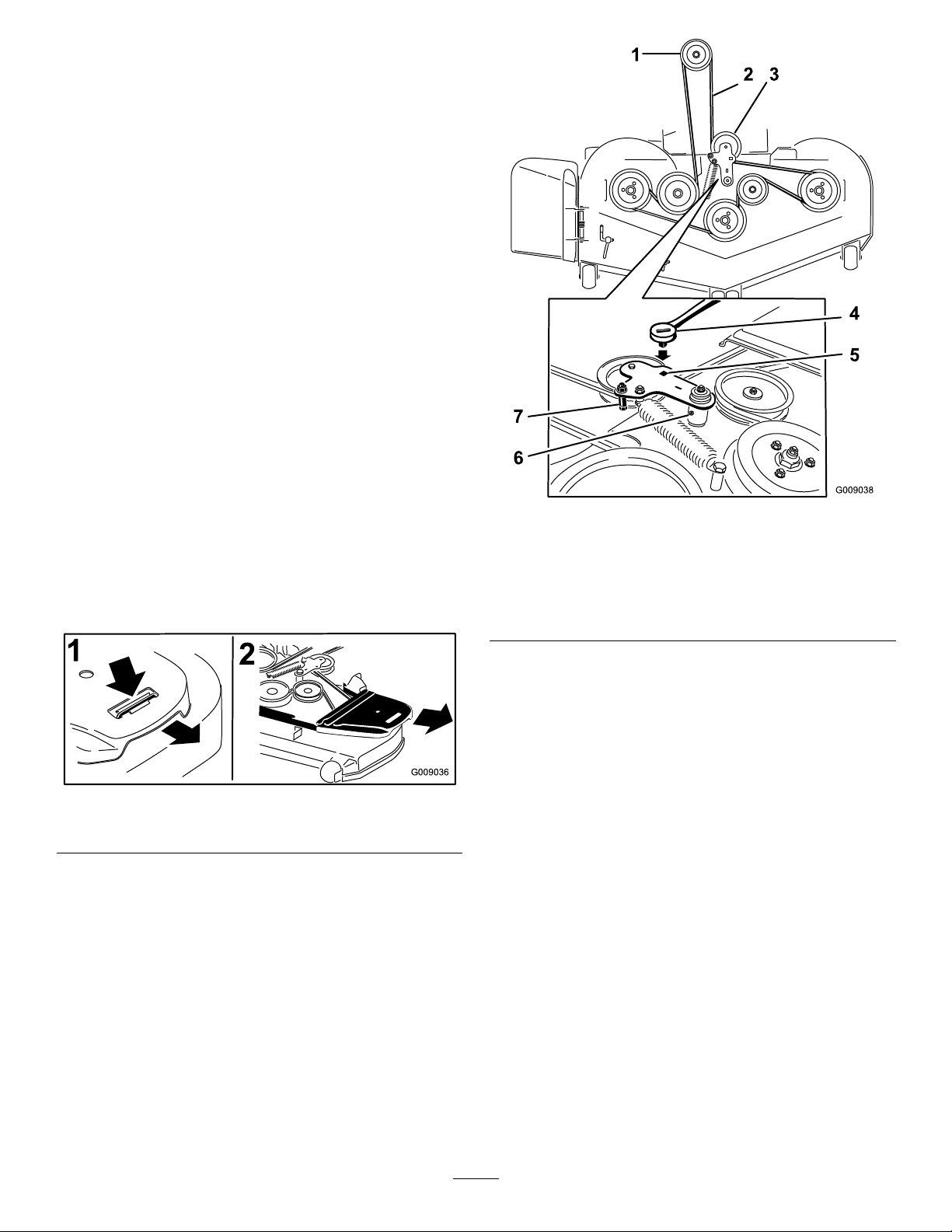
BeltMaintenance
G009036
1
2
InspectingtheBelts
ServiceInterval:Every50hours
Checkthebeltsforsquealingwhenthebeltisrotating,
bladesslippingwhencuttinggrass,frayedbeltedges,
burnmarksandcracksaresignsofawornmowerbelt.
Replacethemowerbeltifanyoftheseconditionsare
evident.
ReplacingtheMowerBelt
Squealingwhenthebeltisrotating,bladesslippingwhen
cuttinggrass,frayedbeltedges,burnmarksandcracks
aresignsofawornmowerbelt.Replacethemowerbelt
ifanyoftheseconditionsareevident.
1.DisengagethePTO ,movethemotioncontrollevers
totheneutrallockedpositionandsettheparking
brake.
2.Stoptheengine,removethekey,andwaitforall
movingpartstostopbeforeleavingtheoperating
position.
3.Lowerthemowertothe3inch(76mm)heightofcut.
4.Removethebeltcovers(
1.Pushtabdown2.Removebeltcover
5.Usearatchetinthesquareholeintheidlerarmto
removetensionontheidlerspring(Figure74).
6.Removethebeltfromthemowerdeckpulleys.
7.Removethebeltguideonthespringloadedidlerarm
showninFigure74.
Figure73).
Figure73
Figure74
1.Clutchpulley5.Squareholeintheidler
2.Mowerbelt6.Idlergreasezerk
3.Springloadedidlerpulley
4.Ratchet
10.Installthebeltguideontheidlerarmshownin
Figure74.
11.Usingtheratchetinthesquarehole,installtheidler
spring(Figure74).
Makesurethespringendsareseatedintheanchor
grooves.
12.Installthebeltcovers(
armfortheratchet
7.Beltguide
Figure75).
8.Removetheexistingbelt.
9.Installthenewbeltaroundthemowerpulleysand
theclutchpulleyundertheengine(Figure74).
49
Page 50
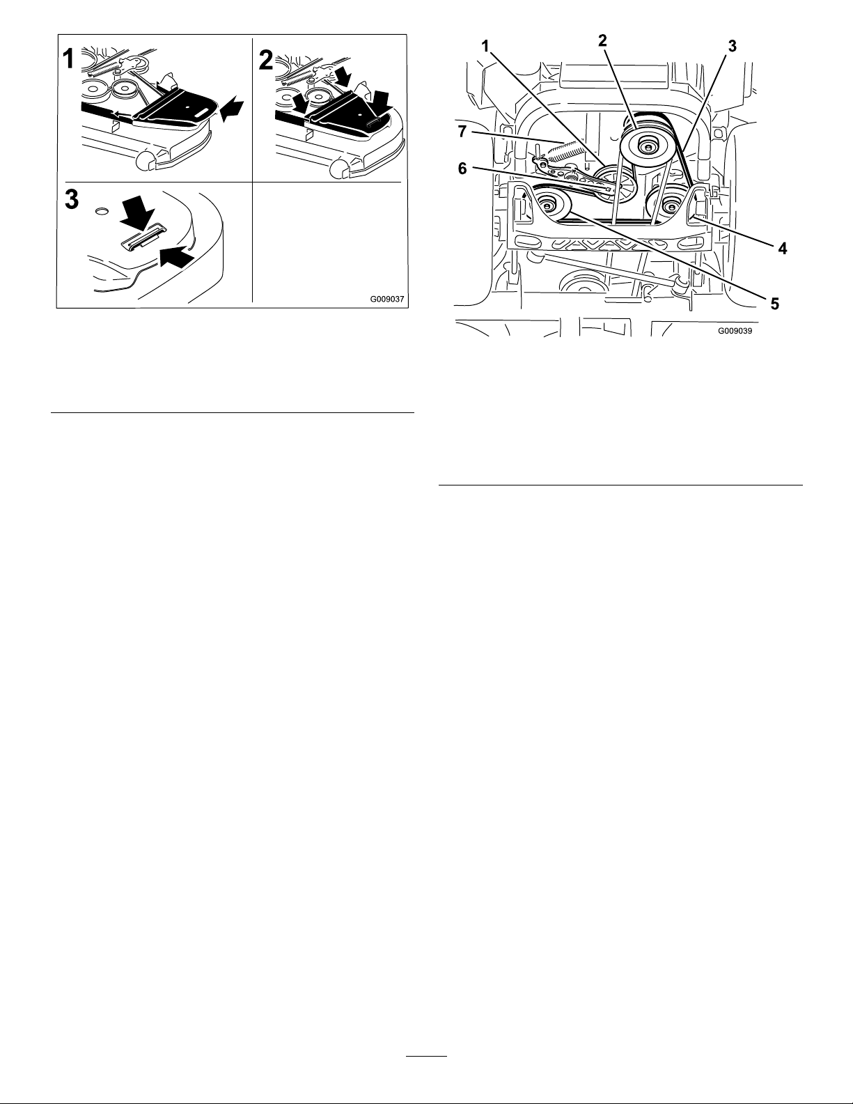
Figure75
1.Positionthebeltcover3.Ensurethetabisunder
2.Slidebeltcoverunderthe
sidecatches
themetalcatch
ReplacingtheHydraulicPump
DriveBelt
1.DisengagethePTOandsettheparkingbrake.
2.Stoptheengine,removethekey,andwaitforall
movingpartstostopbeforeleavingtheoperating
position.
3.Removemowerbelt.RefertoReplacingtheMower
BeltinMaintenance.
4.Raisethemachineandsupportitwithjackstands
Figure76).
(
Figure76
1.Idlerpulley
2.Clutchpulley6.Squareholeinidlerarm
3.Pumpdrivebelt7.Idlerspring
4.Righthandhydraulicpump
pulley
5.Lefthandhydraulicpump
pulley
5.Usearatchetinthesquareholeintheidlerarmto
removetheidlerspring(Figure76).
6.Unhooktheidlerspringfromtheframe(
Figure76).
7.Removethebeltfromthehydraulicunitdrivepulleys
andtheenginepulley
8.Installthenewbeltaroundenginepulleyandthetwo
drivepulleys.
9.Usingaratchetinthesquareholeintheidlerarm,
installtheidlerspringtotheframe(
Figure76).
10.Installthemowerbelt.RefertoReplacingtheMower
Belt.
50
Page 51
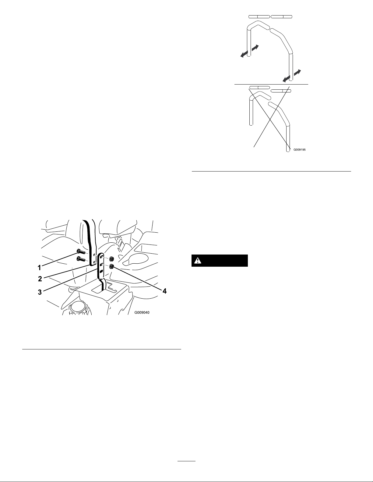
ControlsSystem
Maintenance
AdjustingtheControlHandle
Position
Therearetwoheightpositionsforthecontrollevers;
highandlow .Removetheboltstoadjusttheheightfor
theoperator.
1.DisengagethePTO ,movethemotioncontrollevers
totheneutrallockedposition,andsettheparking
brake.
2.Stoptheengine,removethekey,andwaitforall
movingpartstostopbeforeleavingtheoperating
position.
3.Loosentheboltsandangenutsinstalledinthe
levers(
Figure77).
Figure78
4.Aligntheleversfronttorearpositionbybringthe
leverstogethertotheneutralpositionandslide
themuntiltheyarealigned,thentightenthebolts
Figure78).
(
Figure77
1.Bolt
2.Handle4.Nut
3.Controllever
AdjustingtheMotionControl
Linkage
Locatedoneithersideofthefueltank,belowtheseatare
thepumpcontrollinkages.Rotatingthepumplinkage
witha1/2inchwrenchallowsnetuningadjustments
sothatthemachinedoesnotmoveinneutral.Any
adjustmentsshouldbemadeforneutralpositioningonly.
WARNING
Enginemustberunninganddrivewheelsmust
beturningsomotioncontroladjustmentcanbe
performed.Contactwithmovingpartsorhot
surfacesmaycausepersonalinjury.
Keepngers,hands,andclothingclearofrotating
componentsandhotsurfaces.
1.Priortostartingtheengine,pushthedeckliftpedal
andremovetheheightofcutpin.Lowerdeckto
theground.
2.Raisetherearofmachineupandsupportwithjack
stands(orequivalentsupport)justhighenoughto
allowdrivewheelstoturnfreely.
3.Removetheelectricalconnectionfromtheseat
safetyswitch,locatedunderthebottomcushionof
theseat.Theswitchisapartoftheseatassembly.
4.Temporarilyinstallajumperwireacrossthe
terminalsintheconnectorofthemainwiring
harness.
5.Startengine.Brakemustbeengagedandmotion
controlleversouttostartengine.Operatordoes
51
Page 52
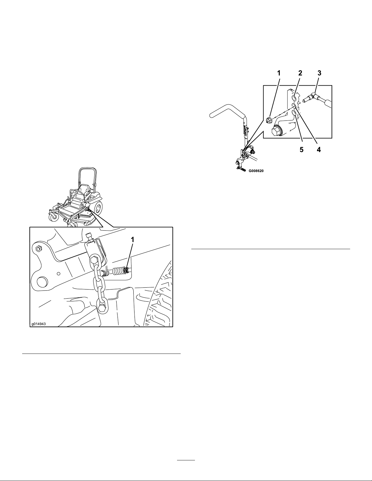
nothavetobeintheseatbecauseofthejumper
g014943
wirebeingused.Runengineatfullthrottleand
releasebrake.
AdjustingtheMotionControl
Damper
6.Runtheunitatleast5minuteswiththedrivelevers
atfullforwardspeedtobringhydraulicoilupto
operatingtemperature.
Note:Themotioncontrolleverneedstobein
neutralwhilemakinganynecessaryadjustments.
7.Bringthemotioncontrolleversintotheneutral
position.Adjustpumpcontrolrodlengthsby
rotatingthedoublenutsontherodintheappropriate
directionuntilthewheelsslightlycreepinreverse
Figure79).Movethemotioncontrolleverstothe
(
reversepositionandwhileapplyingslightpressureto
theleverallowthereverseindicatorspringstobring
theleversbacktoneutral.Thewheelsmuststop
turningorslightlycreepinreverse.
Thetopdampermountingboltcanbeadjustedtoobtain
amoredesiredmotioncontrolleverresistance.See
Figure80formountingoptions.
Figure80
RHMotionControlShown
1.Torquethelocknutto200in-lb(16.7ft-lb).Boltmust
protrudepastendoflocknutaftertorque.
2.Mostresistance(rmestfeel)
3.Damper
4.Mediumresistance(mediumfeel)
5.Leastresistance(softestfeel)
Figure79
1.Doublenuts
8.Shutoffunit.Removejumperwirefromwire
harnessandplugconnectorintoseatswitch.
9.Removethejackstands.
10.Raisethedeckandre-installtheheightofcutpin.
11.Checkthatthemachinedoesnotcreepinneutral
withtheparkbrakesdisengaged.
AdjustingtheMotionControl
NeutralLockPivot
Theangednutcanbeadjustedtoobtainamoredesired
motioncontrolleverresistancewhenmovingittothe
neutrallockposition.SeeFigure81foradjustment
options.
1.Loosenthejamnut.
2.Tightenorloosentheangednuttothedesiredfeel.
Formoreresistance,tightentheangednut.
Forlessresistance,loosentheangednut
3.Tightenjamnut.
52
Page 53

HydraulicSystem
Maintenance
ServicingtheHydraulic
System
Figure81
1.Flangednut2.Jamnut
115W-50.
®
HYPR-OIL
HydraulicOilType:Toro
hydraulicoilorMobil
Important:Useoilspecied.Otheruidscould
causesystemdamage.
EachHydraulicSystemOilCapacity:52ounces(1.5
l)persidewithlterchange
®
™
500
CheckingtheHydraulicOil
ServiceInterval:Every50hours—Checkthehydraulic
oillevel.
1.Positionthemachineonalevelsurface.
2.DisengagethePTO ,movethemotioncontrollevers
totheneutrallockedpositionandsettheparking
brake.
3.Stoptheengine,removethekey,andwaitforall
movingpartstostopbeforeleavingtheoperating
position.
4.Allowtheengineandhydraulicsystemtocoolfor
tenminutes.
Note:Theoillevelonthedipstickwillbeincorrect
whentheoilischeckedandtheunitishot.
5.Movetheseatforward.
6.Cleantheareaaroundthedipsticksofhydraulic
systemreservoirs(
7.Removeonedipstickfromthehydraulicreservoir
Figure82).
(
8.Wipethedipstickoffandthreadthedipstickinto
thereservoir.
9.Removethedipstickandlookattheend(
Iftheoillevelisattheaddmark,slowlypouronly
enoughoilintothehydraulicreservoirtoraisethe
leveltothefullorHline.
Important:Donotoverllthehydraulicunits
withoilasdamagemayoccur.Donotrunthe
machinewiththeoilbelowtheaddmark.
10.Installthedipstick.
11.Repeatprocedurefortheoppositedipstick.
Figure82).
Figure82).
53
Page 54
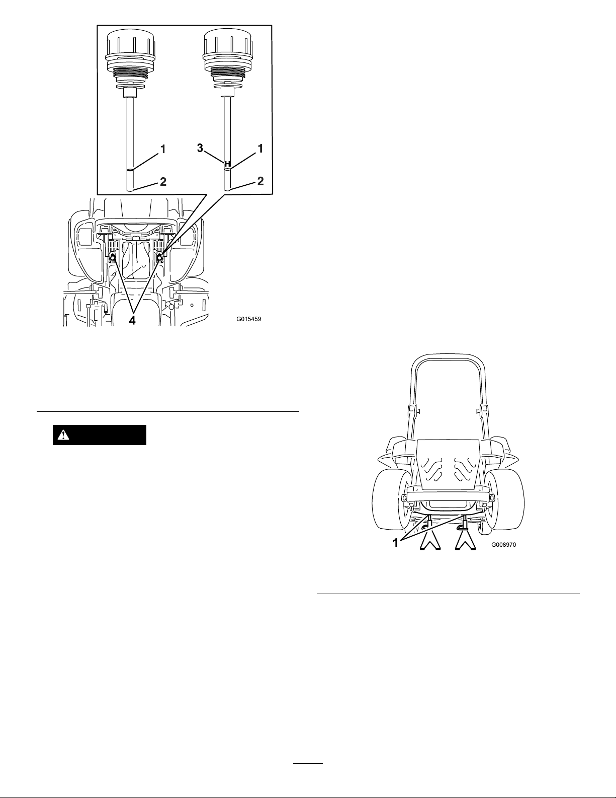
G015459
H
3
4
ReplacingtheHydraulicFiltersand
HydraulicOil
ServiceInterval:Every250hours—Changethe
hydraulicltersandhydraulicoil
whenusingMobil
Every500hours—Changethe
hydraulicltersandhydraulicoil
whenusingToro
hydraulicoil.
Toreplacethehydraulicoil,theltersneedtobe
removed.Replacebothatthesametime.Refertotheoil
specicationsunderServicingtheHydraulicSystemfor
thecorrectoil.
1.Disengagethebladecontrolswitch(PTO),movethe
motioncontrolleverstotheneutrallockedposition
andsettheparkingbrake.
2.Stoptheengine,removethekey,andwaitforall
movingpartstostopbeforeleavingtheoperating
position.
®
1oil.
®
HYPR-OIL
™
500
Figure82
Eitherdipstickwillbeusedinthemachine
1.Full3.H–meanshighlevel
2.Add4.Dipsticklocationsunder
seat
WARNING
Hydraulicoilescapingunderpressurecan
penetrateskinandcauseinjury.
•Ifhydraulicoilisinjectedintotheskinit
mustbesurgicallyremovedwithinafew
hoursbyadoctorfamiliarwiththistypeof
injury.Gangrenemayresultifthisisnot
done.
•Keepbodyandhandsawayfrompinhole
leaksornozzlesthatejecthighpressure
hydraulicoil.
•Usecardboardorpapertondhydraulic
leaks.
•Safelyrelieveallpressureinthehydraulic
systembeforeperforminganyworkonthe
hydraulicsystem.
•Makesureallhydraulicoilhosesandlines
areingoodconditionandallhydraulic
connectionsandttingsaretightbefore
applyingpressuretohydraulicsystem.
3.Raisethemachineandsupportitwithjackstands
Figure83).
(
Figure83
1.Jackstands
4.Removeboththemowerbeltandthepumpdrive
belt.Thiswillpreventoilgettingonthebelts.Refer
toBeltsintheMaintenanceSection.
5.Placeadrainpanunderthelter,removetheold
lterandwipethesurfaceclean(Figure84).
54
Page 55
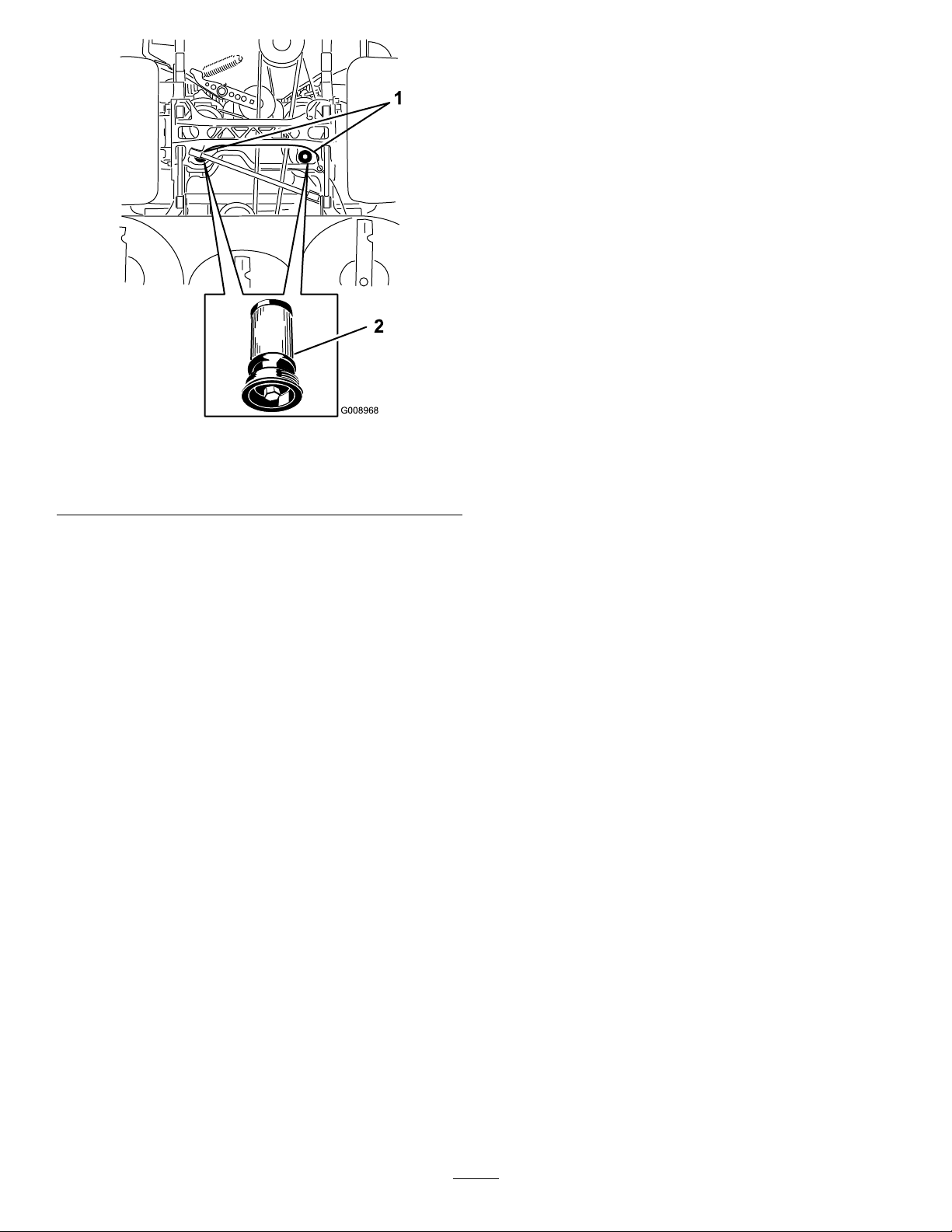
G008968
1
2
Figure84
BottomViewofMachine
1.Filterlocations
6.Applyathincoatofhydraulicoiltotherubber
gasketonthereplacementlter(Figure84).
7.Installthereplacementhydrauliclter.
8.Installthepumpdrivebeltandthemowerbelt.
9.Removethejackstandsandlowerthemachine
Figure83).
(
10.Addoiltothehydraulicreservoirandcheckforany
leaks.
2.Hydrauliclter
MowerDeck
Maintenance
LevelingtheMowerDeck
SettingUptheMachine
Note:Ensurethemowerdeckisleveledbefore
matchingtheheight-of-cut(HOC).
1.Positionmoweronaatsurface.
2.Disengagethebladecontrolswitch(PTO),movethe
motioncontrolleverstotheneutrallockedposition
andsettheparkingbrake.
3.Stoptheengine,removethekey,andwaitforall
movingpartstostopbeforeleavingtheoperating
position.
4.Checktirepressureofthetires.Ifneeded,adjustto
13psi(90kPa)
5.Positionthemowertothe3inch(76mm)
height-of-cutposition.
DeckLeveling
1.Positionthemoweronaatsurface.
2.Stopengine,waitforallmovingpartstostop,and
removekey .Engageparkingbrake.
3.Checkthetirepressureinthedrivetires.Proper
inationpressurefortiresis13psi(90kPa).Adjust
ifnecessary.
11.Cleanupanyspilledoil.
12.Starttheengineandletitrunforabouttwominutes
topurgeairfromthesystem.Stoptheengineand
checkforleaks.
13.Checktheoillevelwhiletheoiliscold.
14.Ifrequired,addoiltothehydraulicreservoir.Do
notoverll.
4.Positionthetransportlockinthelatchingposition.
5.Pushthedeckliftpedalallthewayforwardandthe
deckwilllatchatthe51/2inch(14cm)transport
position(
55
Figure85).
Page 56
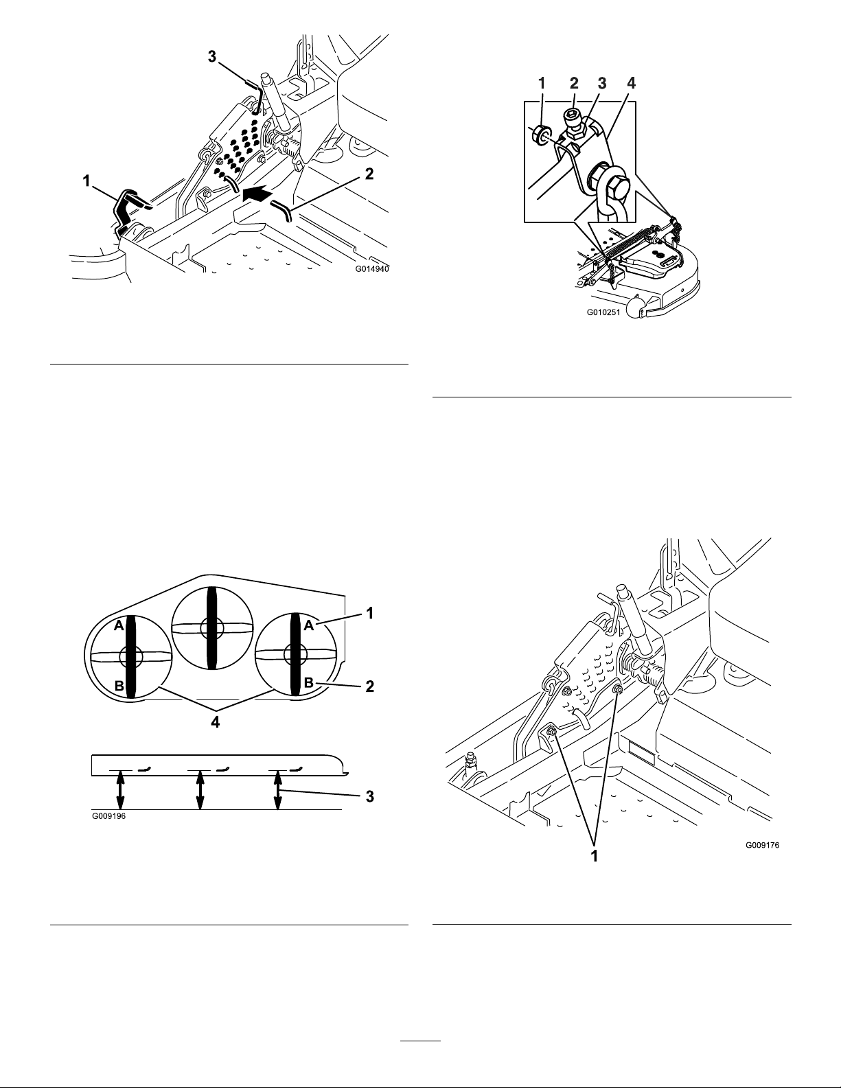
G014940
Figure85
Toincreasetheheight,turntheadjusterscrew
clockwise;todecrease,turncounterclockwise.
1.Deckliftpedal
2.Heightofcutpin
3.Transportlock
6.Inserttheheightadjustmentpinintothe3inch(7.6
cm)cuttingheightlocation.
7.Releasethetransportlockandallowthedeckto
lowertothecuttingheight.
8.Raisethedischargechute.
9.Onbothsidesofthedeck,measurefromthelevel
surfacetothefronttipoftheblade(PostionA).
Themeasurementshouldread3inches(7.6mm)
(Figure86).
Figure87
1.Whizlocknut3.Jamnut
2.Adjusterscrew4.Y oke
11.Ifthefrontdecklinksdonothaveenoughadjustment
toachieveaccuratecutheight,thesinglepoint
adjustmentcanbeutilizedtogainmoreadjustment.
12.Toadjustthesinglepointsystem,loosenthetwo
boltsatthebottomoftheheightofcutplate.Refer
Figure88.
to
Figure86
1.3inches(7.6cm)atAis
correct
2.31/4inches(8.3cm)atB
iscorrect
3.Measureherefromthe
bladetiptohardsurface
4.MeasureatAandBon
bothsides
10.Ifneeded,loosenthewhizlocknutonthesideofthe
yokeandthejamnutontop.Finetunethescrew
adjusterbyturningittoget3inch(7.6mm)height
(seeFigure87).
Figure88
1.Boltsatthebottomoftheheight-of-cutplate
13.Ifthedeckistoolow,tightenthesinglepoint
adjustmentboltbyrotatingitclockwise.Ifthedeck
istoohigh,loosenthesinglepointadjustmentbolt
byrotatingitcounterclockwise(Figure89).
56
Page 57
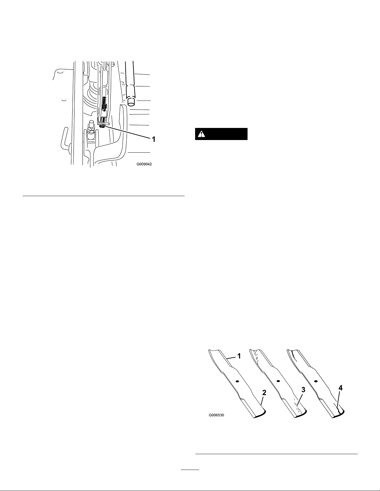
Note:Loosenortightenthesinglepointadjustment
boltenoughtomovetheheight-of-cutplate
mountingboltsatleast1/3thelengthoftheavailable
travelintheirslots.Thiswillregainsomeupand
downadjustmentoneachofthefourdecklinks.
Figure89
1.Singlepointadjustmentbolt
14.Tightenthetwoboltsatthebottomoftheheightof
cutplate(Figure88).Torqueto27-33ft-lb(37-45
N-m).
ServicingtheCuttingBlades
Maintainsharpbladesthroughoutthecuttingseason
becausesharpbladescutcleanlywithouttearingor
shreddingthegrassblades.Tearingandshreddingturns
grassbrownattheedges,whichslowsgrowthand
increasesthechanceofdisease.
Checkthecutterbladesdailyforsharpness,andforany
wearordamage.Filedownanynicksandsharpenthe
bladesasnecessary.Ifabladeisdamagedorworn,
replaceitimmediatelywithagenuineTororeplacement
blade.Forconvenientsharpeningandreplacement,you
maywanttokeepextrabladesonhand.
DANGER
Awornordamagedbladecanbreak,andapiece
ofthebladecouldbethrownintotheoperator's
orbystander'sarea,resultinginseriouspersonal
injuryordeath.
•Inspectthebladeperiodicallyforwearor
damage.
•Replaceawornordamagedblade.
BeforeInspectingorServicingthe
Blades
Note:Inmostconditions,thebackbladetipshould
beadjusted1/4inch(6.4mm)higherthanthefront.
15.Onbothsidesofthedeck,measurefromthelevel
surfacetothebacktipoftheblade(PostionB).The
measurementshouldread31/4inches(8.3cm)
Figure86).
(
16.Finetunethescrewadjusterbyturningittoget
3–1/4inches(8.3mm)height(
Figure87).
Toincreasetheheight,turntheadjustmentnut
clockwise;todecrease,turncounterclockwise.
17.Measureuntilallfoursidesarethecorrectheight.
Tightenallthenutsonthedeckliftarmassemblies.
18.Lowerdischargechute.
Parkthemachineonalevelsurface,disengagetheblade
controlswitch(PTO),andsettheparkingbrake.Turn
theignitionkeytoOff.Removethekey.
InspectingtheBlades
ServiceInterval:Beforeeachuseordaily
1.Inspectthecuttingedges(Figure90).Iftheedges
arenotsharporhavenicks,removeandsharpenthe
blades.RefertoSharpeningtheBlades.
2.Inspecttheblades,especiallythecurvedarea
(Figure90).Ifyounoticeanydamage,wear,oraslot
forminginthisarea(
newblade.
Figure90),immediatelyinstalla
Figure90
1.CuttingEdge3.Wear/slotForming
2.CurvedArea4.Crack
57
Page 58
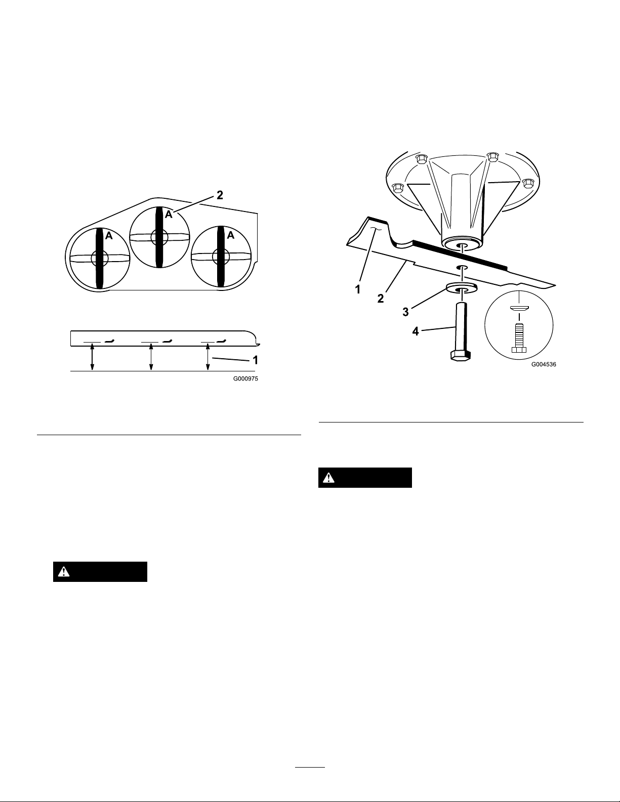
CheckingforBentBlades
1.Disengagethebladecontrolswitch(PTO),movethe
motioncontrolleverstotheneutrallockedposition
andsettheparkingbrake.
2.Stoptheengine,removethekey,andwaitforall
movingpartstostopbeforeleavingtheoperating
position.
3.Rotatethebladesuntiltheendsfaceforwardand
backward(Figure91).Measurefromalevelsurface
tothecuttingedge,positionA,oftheblades
Figure91).Notethisdimension.
(
performanceandcontinuedsafetyconformanceof
themachine,usegenuineTororeplacementblades.
Replacementbladesmadebyothermanufacturersmay
resultinnon-conformancewithsafetystandards.
1.Holdthebladeendusingaragorthickly-padded
glove.
2.Removethebladebolt,curvedwasher,andblade
fromthespindleshaft(
Figure92).
Figure91
1.Measureherefromblade
tohardsurface
2.PositionA
4.Rotatetheoppositeendsofthebladesforward.
5.Measurefromalevelsurfacetothecuttingedgeof
thebladesatthesamepositionasinstep3above.
Thedifferencebetweenthedimensionsobtainedin
3and4mustnotexceed1/8inch(3mm).If
steps
thisdimensionexceeds1/8inch(3mm),theblade
isbentandmustbereplaced;refertoRemovingthe
BladesandInstallingtheBlades.
WARNING
Abladethatisbentordamagedcouldbreak
apartandcouldseriouslyinjureorkillyouor
bystanders.
•Alwaysreplacebentordamagedbladewith
anewblade.
•Neverleorcreatesharpnotchesinthe
edgesorsurfacesofblade.
Figure92
1.SailAreaofBlade3.Curvedwasher
2.Blade4.BladeBolt
SharpeningtheBlades
WARNING
Whensharpeningblade,piecesofbladecouldbe
thrownandcauseseriousinjury.
Wearpropereyeprotectionwhensharpeningblade.
1.Usealetosharpenthecuttingedgeatbothends
oftheblade(
Thebladeretainsitsbalanceifthesameamountof
materialisremovedfrombothcuttingedges.
Figure93).Maintaintheoriginalangle.
RemovingtheBlades
Bladesmustbereplacedifasolidobjectishit,ifthe
bladeisoutofbalanceorisbent.Toensureoptimum
58
Page 59
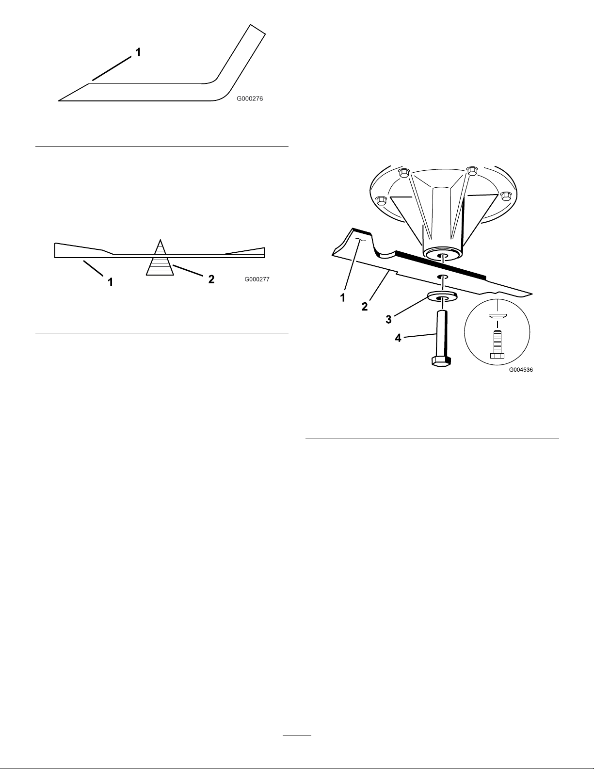
Figure93
1.Sharpenatoriginalangle
2.Checkthebalanceofthebladebyputtingitona
bladebalancer(Figure94).Ifthebladestaysina
horizontalposition,thebladeisbalancedandcanbe
used.Ifthebladeisnotbalanced,lesomemetaloff
theendofthesailareaonly(
Figure95).Repeatthis
procedureuntilthebladeisbalanced.
Figure94
InstallingtheBlades
1.Installthebladeontothespindleshaft(Figure95).
Important:Thecurvedpartoftheblademust
bepointingupwardtowardtheinsideofthe
mowertoensurepropercutting.
2.Installthespringdiskandbladebolt.Thespring
diskconemustbeinstalledtowardthebolthead
Figure95).Torquethebladeboltto85-110ft-lb
(
(115-150N-m).
1.Blade2.Balancer
1.SailAreaofBlade
2.Blade
3.SpringDisk
Figure95
4.BladeBolt
5.ConeTowardsBoltHead
59
Page 60
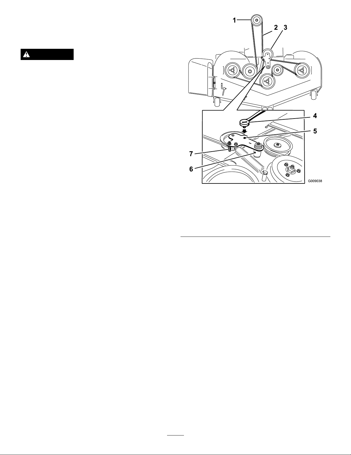
RemovingtheMowerDeck
Beforeservicingorremovingthemowerdeck,thespring
loadeddeckarmsmustbelockedout.
WARNING
Deckliftarmassemblieshavestoredenergy.
Removingthedeckwithoutreleasingthestored
energycancauseseriousinjuryordeath.
DoNotattempttodisassemblethedeckfromthe
frontframewithoutlockingoutthestoredenergy.
1.Stopengine,waitforallmovingpartstostop,and
removekey .Engageparkingbrake.
2.Removetheheightadjustmentpinandlowerthe
decktotheground.
3.Placetheheightadjustmentpininthe3inch(7.6cm)
cuttingheightlocation.Thislocksthedeckliftarms
inthelowestpositionwhenthedeckisremovedand
thestoredenergyinthedeckspringisreleased.
4.Removethebeltcovers.
5.Liftuptheoorpanandinsertaratchetintothe
squareholeinthedeckidler(
Figure96).
6.Rotatethedeckidlerclockwiseandremovethe
mowerbelt(
Figure96).
Figure96
1.Clutchpulley5.Squareholeintheidler
2.Mowerbelt6.Idlergreasezerk
3.Springloadedidlerpulley
4.Ratchet
armfortheratchet
7.Beltguide
7.Removeandretainthehardwareonbothsidesofthe
deckasshowninFigure97.
60
Page 61
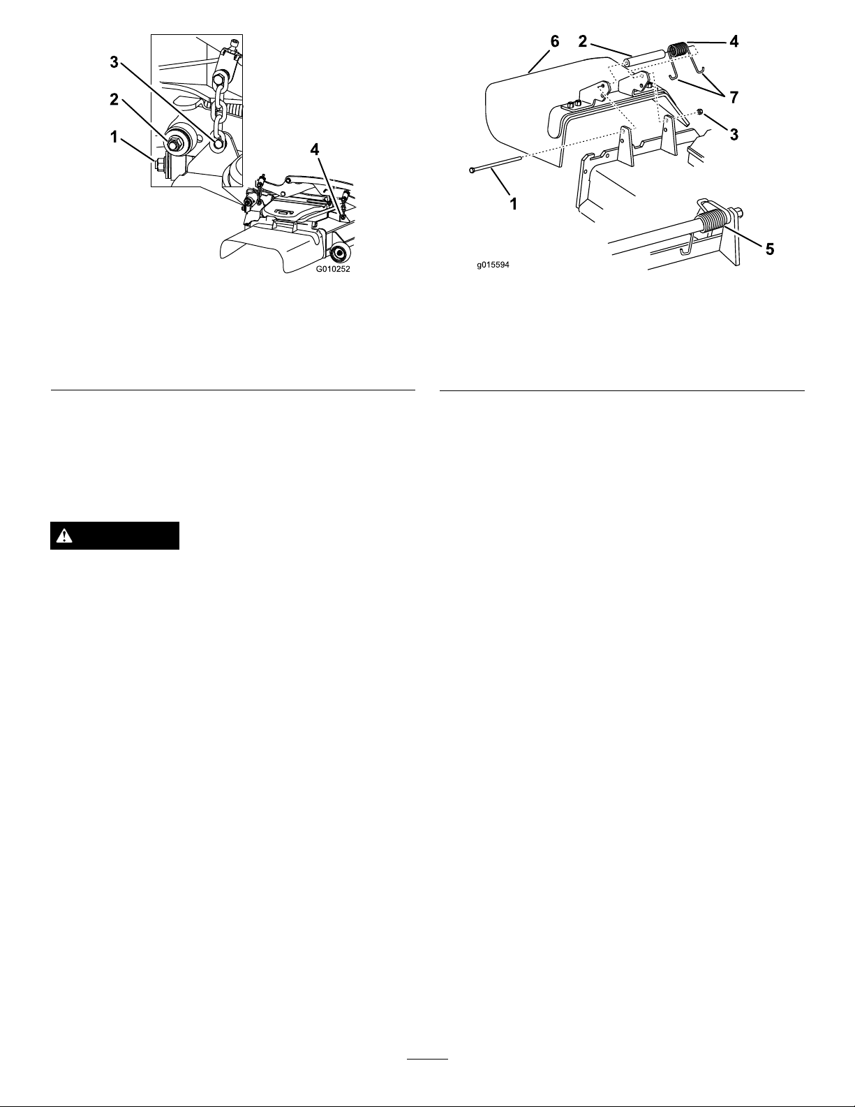
Figure97
g015594
1
6 2
4
7
3
5
1.Rightstabilizer
2.Deckstrut(rightsideshown)
3.Removethereardeckliftattachmentshoulderboltandnut.
4.Removethefrontdeckliftattachmentshoulderboltandnut.
Figure98
1.Bolt
2.Spacer6.GrassDeector
3.Locknut
4.Spring
5.Springinstalled
7.Jhookendofspring
8.Raisethedeckstrutsandsecurethemintheup
position.Slidethedeckouttotherightsideofthe
machine.
ReplacingtheGrassDeector
WARNING
Anuncovereddischargeopeningcouldallowthe
lawnmowertothrowobjectsintheoperator'sor
bystander'sdirectionandresultinseriousinjury.
Also,contactwiththebladecouldoccur.
Neveroperatethelawnmowerunlessyouinstalla
coverplate,amulchplate,grassdeectororbagger.
1.Removethelocknut,bolt,springandspacerholding
thedeectortothepivotbrackets(Figure98).
Removedamagedorworngrassdeector.
2.Placespacerandspringontograssdeector.Place
oneJendofspringbehinddeckedge.
Note:MakesureoneJendofspringisinstalled
behinddeckedgebeforeinstallingtheboltasshown
Figure98.
in
3.Installboltandnut.PlaceoneJhookendofspring
aroundgrassdeector(Figure98).
Important:Thegrassdeectormustbeable
torotate.Liftthedeectoruptothefullopen
positionandensurethatitrotatesintothefull
downposition.
61
Page 62

Cleaning
Storage
CleaningUndertheMower
ServiceInterval:Beforeeachuseordaily
1.Disengagethebladecontrolswitch(PTO),movethe
motioncontrolleverstotheneutrallockedposition
andsettheparkingbrake.
2.Stoptheengine,removethekey,andwaitforall
movingpartstostopbeforeleavingtheoperating
position.
3.Raisethemowertothetransportposition.
WasteDisposal
Engineoil,batteries,hydraulicoil,andenginecoolant
arepollutantstotheenvironment.Disposeofthese
accordingtoyourstateandlocalregulations.
CleaningandStorage
1.Disengagethepowertakeoff(bladecontrolswitch
(PTO),settheparkingbrake,andturntheignition
keytoOff.Removethekey.
2.Removegrassclippings,dirt,andgrimefromthe
externalpartsoftheentiremachine,especiallythe
engineandhydraulicsystem.Cleandirtandchaff
fromtheoutsideoftheenginecylinderheadnsand
blowerhousing.
Important:Youcanwashthemachinewith
milddetergentandwater.Donotpressure
washthemachine.Avoidexcessiveuseof
water,especiallynearthecontrolpanel,engine,
hydraulicpumps,andmotors.
3.Checkthebrake;refertoServicingtheBrakeinthe
MaintenanceSection.
4.Servicetheaircleaner;refertoServicingtheAir
CleanerintheMaintenanceSection.
5.Greasethemachine;refertoGreasingand
LubricationintheMaintenanceSection.
6.Changethecrankcaseoil;refertoServicingthe
EngineOilintheMaintenanceSection.
7.Checkthetirepressure;refertoCheckingtheTire
PressureintheMaintenanceSection.
8.Changethehydrauliclters;refertoServicingthe
HydraulicSystemintheMaintenanceSection.
9.Chargethebattery;refertoServicingtheBatteryin
theMaintenanceSection.
10.Scrapeanyheavybuildupofgrassanddirtfromthe
undersideofthemower,thenwashthemowerwith
agardenhose.
Note:Runthemachinewiththebladecontrol
switch(PTO)engagedandtheengineathighidlefor
2to5minutesafterwashing.
11.Checktheconditionoftheblades;refertoServicing
theCuttingBladesintheMaintenanceSection.
12.Preparethemachineforstoragewhennon-use
occursover30days.Preparethemachineforstorage
asfollows:
A.Addapetroleumbasedstabilizer/conditioner
tofuelinthetank.Followmixinginstructions
fromthestabilizermanufacturer.Donotusean
alcoholbasedstabilizer(ethanolormethanol).
Note:Afuelstabilizer/conditionerismost
effectivewhenmixedwithfreshfuelandused
atalltimes.
62
Page 63

B.Runtheenginetodistributeconditionedfuel
throughthefuelsystem(5minutes).
C.Stoptheengine,allowittocool,anddrainthe
fueltank;refertoServicingtheFuelTankinthe
MaintenanceSection.
D.Restarttheengineandrunituntilitstops.
E.Disposeoffuelproperly.Recycleasperlocal
codes.
Important:Donotstore
stabilizer/conditionedfuelover90days.
13.Checkandtightenallbolts,nuts,andscrews.Repair
orreplaceanypartthatisdamaged.
14.Paintallscratchedorbaremetalsurfaces.Paintis
availablefromyourAuthorizedServiceDealer.
15.Storethemachineinaclean,drygarageorstorage
area.Removethekeyfromtheignitionswitchand
keepitoutofreachofchildrenorotherunauthorized
users.Coverthemachinetoprotectitandkeepit
clean.
63
Page 64

Troubleshooting
Problem
Starterdoesnotcrank
Enginewillnotstart,startshard,orfails
tokeeprunning
PossibleCauseCorrectiveAction
1.Bladecontrolswitch(PTO)isengaged.1.Movebladecontrolswitch(PTO)to
2.Parkingbrakeisnoton.
3.Driveleversarenotinneutrallock
position.
4.Operatorisnotseated.4.Sitontheseat.
5.Batteryisdead.
6.Electricalconnectionsarecorrodedor
loose.
7.Fuseisblown.
8.Relayorswitchisdefective.8.ContactanAuthorizedServiceDealer.
1.Fueltankisempty.
2.Fuelshutoffvalveisclosed.2.Openthefuelshutoffvalve.
3.Oillevelinthecrankcaseislow.
4.Thethrottleandchokearenotinthe
correctposition.
5.Dirtinfuellter.5.Replacethefuellter.
6.Dirt,water,orstalefuelisinthefuel
system.
7.Aircleanerisdirty.
8.Seatswitchisnotfunctioningproperly .8.Checktheseatswitchindicator.
9.Electricalconnectionsarecorroded,
looseorfaulty.
10.Relayorswitchisdefective.10.ContactanAuthorizedServiceDealer.
11.Faultysparkplug.
12.Sparkplugwireisnotconnected.12.Checkthesparkplugwireconnection.
disengaged.
2.Settheparkingbrake.
3.Ensurethedriveleversareinthe
neutrallockposition.
5.Chargethebattery.
6.Checktheelectricalconnectionsfor
goodcontact.
7.Replacefuse.
1.Fillthefueltank.
3.Addoiltothecrankcase.
4.Besurethethrottlecontrolismidway
betweenthe“SLOW”and“FAST”
positions,andthechokeisinthe“ON”
positionforacoldengineorthe“OFF”
positionforawarmengine.
6.ContactanAuthorizedServiceDealer.
7.Cleanorreplacetheaircleaner
element.
Replaceseatifneeded.
9.Checktheelectricalconnections
forgoodcontact.Cleanconnector
terminalsthoroughlywithelectrical
contactcleaner,applydielectricgrease
andreconnect.
11.Clean,adjustorreplacesparkplug.
Enginelosespower.
Engineoverheats.
Mowerpullsleftorright(withleversfully
forward)
1.Engineloadisexcessive.1.Reducethegroundspeed.
2.Aircleanerisdirty.
3.Oillevelinthecrankcaseislow.
4.Coolingnsandairpassagesabove
theengineareplugged.
5.Ventholeinthefuelcapisplugged.5.Cleanorreplacethefuelcap.
6.Dirtinthefuellter.6.Replacethefuellter.
7.Dirt,water,orstalefuelisinthefuel
system.
1.Engineloadisexcessive.1.Reducethegroundspeed.
2.Oillevelinthecrankcaseislow.
3.Coolingnsandairpassagesabove
theengineareplugged.
1.Trackingneedsadjustment1.Adjustthetracking.
2.Tirepressureindrivetiresnotcorrect.2.Adjusttirepressureinthedrivetires.
2.Cleantheaircleanerelement.
3.Addoiltothecrankcase.
4.Removetheobstructionfromthe
coolingnsandairpassages.
7.ContactanAuthorizedServiceDealer.
2.Addoiltothecrankcase.
3.Removetheobstructionfromthe
coolingnsandairpassages.
64
Page 65

Problem
PossibleCauseCorrectiveAction
Machinedoesnotdrive.
Abnormalvibration.
Unevencuttingheight.
1.Bypassvalvesisnotclosedtight.1.Tightenthebypassvalves.
2.Pumpbeltisworn,looseorbroken.
3.Pumpbeltisoffapulley.3.Changethebelt.
4.Brokenormissingidlerspring.4.Replacethespring.
5.Hydraulicoillevelislowortoohot.5.Addhydraulicoiltoreservoirsorletit
1.Cuttingblade(s)is/arebentor
unbalanced.
2.Blademountingboltisloose.2.Tightentheblademountingbolt.
3.Enginemountingboltsareloose.3.Tightentheenginemountingbolts.
4.Looseenginepulley ,idlerpulley,or
bladepulley .
5.Enginepulleyisdamaged.
6.Bladespindleisbent.
7.Motormountislooseorworn.
1.Blade(s)notsharp.1.Sharpentheblade(s).
2.Cuttingblade(s)is/arebent.2.Installnewcuttingblade(s).
3.Mowerdeckisnotlevel.
4.Undersideofmowerisdirty.4.Cleantheundersideofthemower.
5.Tirepressureisnotcorrect.5.Adjustthetirepressure.
6.Bladespindlebent.
2.Changethebelt.
cooldown.
1.Installnewcuttingblade(s).
4.Tightentheappropriatepulley.
5.ContactanAuthorizedServiceDealer.
6.ContactanAuthorizedServiceDealer.
7.ContactanAuthorizedServiceDealer.
3.Levelmowerdeckfromside-to-side
andfront-to-rear.
6.ContactanAuthorizedServiceDealer.
Bladesdonotrotate.
Clutchwillnotengage.
1.Mowerdeckbeltisworn,looseor
broken.
2.Mowerdeckbeltisoffpulley.
3.Pumpdrivebeltisworn,looseor
broken.
4.Brokenormissingidlerspring.4.Replacethespring.
1.Fuseisblown.
2.Lowvoltagesupplyattheclutch.
3.Damagedcoil.3.Replaceclutch.
4.Inadequatecurrentsupply.4.Repairorreplaceclutchleadwireor
5.Rotor/armatureairgapistoolarge.
1.Installnewdeckbelt.
2.Installmowerdeckpulleyandcheck
theidlerpulley ,idlerarmandspringfor
correctpositionandfunction.
3.Checkthebelttensionorinstallnew
belt.
1.Replacefuse.Checkcoilresistance,
batterycharge,chargingsystem,and
wiringconnectionsandreplaceif
necessary.
2.Checkcoilresistance,battery
charge,chargingsystem,andwiring
connectionsandreplaceifnecessary.
electricalsystem.Cleanconnector
contacts.
5.Removeshimorreplaceclutch.
65
Page 66
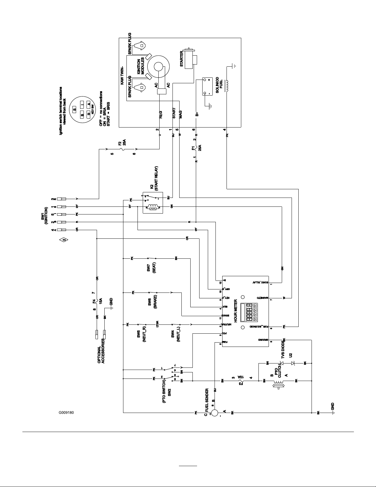
Schematics
WireDiagram(Rev.A)
66
Page 67

Notes:
67
Page 68

TheToroTotalCoverageWarranty
ALimitedWarranty(seewarrantyperiodsbelow)Contractor
Landscape
Equipment
(LCE)
ConditionsandProductsCovered
TheToroCompanyanditsafliate,ToroWarrantyCompany ,pursuantto
anagreementbetweenthem,jointlypromisetotheoriginalpurchaser
torepairtheToroProductslistedbelowifdefectiveinmaterialsor
workmanship.
Thefollowingtimeperiodsapplyfromthedateofpurchasebytheoriginal
owner:
ProductsWarrantyPeriod
AllMowers
•Engine
Seeenginemanufacturer'swarranty
•Battery90daysPartsandLabor
1yearPartsonly
•BeltsandTires90days
•Attachments1year
21in.HeavyDutyMowers1yearcommercialUse
2yearsResidentialUse
Mid-SizeWalk-BehindMowers
GrandStand
TM
Mowers
•Frame
ZMaster
®
Z400,Z500Mowers4yearsor1,200hours
•Frame
ZMaster
®
G3Mowers
•Frame
1
SomeenginesusedonT oroLCEProductsarewarrantedbytheenginemanufacturer.
2
Residentialusemeansuseoftheproductonthesamelotasyourhome.Useatmorethanone
locationisconsideredcommercialuseandthecommercialwarrantywouldapply .
3
Whicheveroccursrst.
4
LifetimeFrameWarranty-Ifthemainframe,consistingofthepartsweldedtogethertoformthe
tractorstructurethatothercomponentssuchastheenginearesecuredto,cracksorbreaksin
normaluse,itwillberepairedorreplaced,atToro'soption,underwarrantyatnocostforparts
andlabor.Framefailureduetomisuseorabuseandfailureorrepairrequiredduetorustor
corrosionarenotcovered.
2years
5yearsor1,200hours
Lifetime(originalowneronly)
Lifetime(originalowneronly)
5yearsor1,200hours
Lifetime(originalowneronly)
2
3
4
3
4
3
4
Thiswarrantyincludesthecostofpartsandlabor,butyoumustpay
transportationcosts.
InstructionsforObtainingWarrantyService
IfyouthinkthatyourT oroProductcontainsadefectinmaterialsor
workmanship,followthisprocedure:
1.ContactanyAuthorizedT oroServiceDealertoarrangeserviceattheir
dealership.T olocateadealerconvenienttoyou,refertotheYellow
Pagesofyourtelephonedirectory(lookunder“LawnMowers”)or
accessourwebsiteatwww.T oro.com.Youmayalsocallthenumbers
listedinitem#3tousethe24-hourToroDealerlocatorsystem.
2.Bringtheproductandyourproofofpurchase(salesreceipt)tothe
ServiceDealer.Thedealerwilldiagnosetheproblemanddetermine
ifitiscoveredunderwarranty.
3.IfforanyreasonyouaredissatisedwiththeServiceDealer’s
analysisorwiththeassistanceprovided,contactusat:
RLCCustomerCareDepartment
ToroWarrantyCompany
811 1LyndaleAvenueSouth
Bloomington,MN55420-1196
888-865-5676(U.S.Customers)
888-865-5691(Canadacustomers)
1
OwnerResponsibilities
YoumustmaintainyourT oroProductbyfollowingthemaintenance
proceduresdescribedintheOperator'sManual.Suchroutine
maintenance,whetherperformedbyadealerorbyyou,isatyourexpense.
ItemsandConditionsNotCovered
Thereisnootherexpresswarrantyexceptforspecialemission
systemandenginewarrantycoverageonsomeproducts.
Thisexpresswarrantydoesnotcoverthefollowing:
•Costofregularmaintenanceserviceorwearparts,suchaslters,
fuel,lubricants,tune-upparts,bladesharpening,brakeandclutch
adjustments.
•Anyproductorpartwhichhasbeenalteredormisusedandrequires
replacementorrepairduetonormalwear,accidents,orlackof
propermaintenance.
•Repairsnecessaryduetoimproperfuel,contaminantsinthefuel
system,orfailuretoproperlypreparethefuelsystempriortoany
periodofnon-useoverthreemonths.
•Pickupanddeliverycharges.
GeneralConditions
Allrepairscoveredbythesewarrantiesmustbeperformedbyan
AuthorizedToroServiceDealerusingToroapprovedreplacementparts.
NeitherTheToroCompanynorToroWarrantyCompanyisliablefor
indirect,incidentalorconsequentialdamagesinconnectionwiththe
useoftheT oroProductscoveredbythiswarranty,includingany
costorexpenseofprovidingsubstituteequipmentorserviceduring
reasonableperiodsofmalfunctionornon-usependingcompletion
ofrepairsunderthiswarranty.
Allimpliedwarrantiesofmerchantability(thattheproductistfor
ordinaryuse)andtnessforuse(thattheproductistforaparticular
purpose)arelimitedtothedurationoftheexpresswarranty
Somestatesdonotallowexclusionsofincidentalorconsequential
damages,orlimitationsonhowlonganimpliedwarrantylasts,so
theaboveexclusionsandlimitationsmaynotapplytoyou.
Thiswarrantygivesyouspeciclegalrights,andyoumayalsohaveother
rightswhichvaryfromstatetostate.
CountriesOtherthantheUnitedStatesorCanada
CustomerswhohavepurchasedToroproductsoutsidetheUnitedStatesorCanadashouldcontacttheirT oroDistributor(Dealer)toobtainguarantee
policiesforyourcountry,province,orstate.IfforanyreasonyouaredissatisedwithyourDistributor'sserviceorhavedifcultyobtainingguarantee
information,contacttheToroimporter.Ifallotherremediesfail,youmaycontactusatT oroWarrantyCompany.
374-0252RevC
 Loading...