

Page 1

FormNo.3410-581RevB
ZMaster
®
Professional3000
SeriesRidingMower
with60inTURBOFORCE
Mower
ModelNo.74950—SerialNo.400000000andUp
®
SideDischarge
Registeratwww.T oro.com.
OriginalInstructions(EN)
*3410-581*B
Page 2
ThissparkignitionsystemcomplieswithCanadian
ICES-002
ItisaviolationofCaliforniaPublicResourceCode
Section4442or4443touseoroperatetheengineon
anyforest-covered,brush-covered,orgrass-covered
landunlesstheengineisequippedwithaspark
arrester,asdenedinSection4442,maintainedin
effectiveworkingorderortheengineisconstructed,
equipped,andmaintainedforthepreventionofre.
Pleaserefertotheenginemanufacturer’sinformation
includedwiththemachine.
WARNING
CALIFORNIA
Proposition65Warning
Theengineexhaustfromthisproduct
containschemicalsknowntotheStateof
Californiatocausecancer,birthdefects,
orotherreproductiveharm.
g027332
Figure1
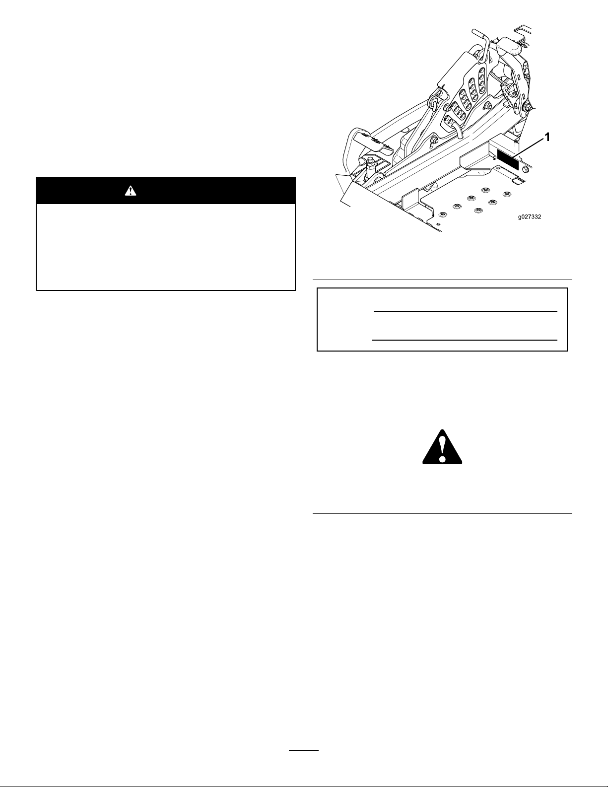
1.Modelandserialnumberlocation
ModelNo.
Introduction
Thisrotary-blade,ridinglawnmowerisintendedtobe
usedbyresidentialhomeownersorprofessional,hired
operators.Itisdesignedprimarilyforcuttinggrasson
well-maintainedlawnsonresidentialorcommercial
properties.Itisnotdesignedforcuttingbrushorfor
agriculturaluses.
Readthisinformationcarefullytolearnhowtooperate
andmaintainyourproductproperlyandtoavoid
injuryandproductdamage.Y ouareresponsiblefor
operatingtheproductproperlyandsafely .
YoumaycontactT orodirectlyatwww.T oro.com
forproductsafetyandoperationtrainingmaterials,
accessoryinformation,helpndingadealer,orto
registeryourproduct.
Wheneveryouneedservice,genuineToroparts,or
additionalinformation,contactanAuthorizedService
DealerorToroCustomerServiceandhavethemodel
andserialnumbersofyourproductready.Figure1
identiesthelocationofthemodelandserialnumbers
ontheproduct.Writethenumbersinthespace
provided.
SerialNo.
Thismanualidentiespotentialhazardsandhas
safetymessagesidentiedbythesafety-alertsymbol
(Figure2),whichsignalsahazardthatmaycause
seriousinjuryordeathifyoudonotfollowthe
recommendedprecautions.
g000502
Figure2
1.Safety-alertsymbol
Thismanualuses2wordstohighlightinformation.
Importantcallsattentiontospecialmechanical
informationandNoteemphasizesgeneralinformation
worthyofspecialattention.
©2018—TheToro®Company
8111LyndaleAvenueSouth
Bloomington,MN55420
Contactusatwww.Toro.com.
2
PrintedintheUSA
AllRightsReserved
Page 3

Contents
Safety.......................................................................4
GeneralSafety...................................................4
SlopeIndicator...................................................5
SafetyandInstructionalDecals..........................6
ProductOverview...................................................12
Controls...........................................................12
Specications..................................................13
BeforeOperation.................................................14
BeforeOperationSafety...................................14
RecommendedFuel.........................................14
UsingStabilizer/Conditioner.............................15
FillingtheFuelTank..........................................15
CheckingtheEngine-OilLevel..........................15
BreakinginaNewMachine..............................15
UsingtheRolloverProtectionSystem
(ROPS).........................................................16
ThinkSafetyFirst..............................................16
UsingtheSafety-InterlockSystem....................17
PositioningtheSeat..........................................18
UnlatchingtheSeat..........................................18
ChangingtheSeatSuspension.........................18
DuringOperation.................................................19
DuringOperationSafety...................................19
OperatingtheParkingBrake.............................20
OperatingtheMowerBlade-ControlSwitch
(PTO)............................................................20
OperatingtheThrottle.......................................21
OperatingtheChoke.........................................21
OperatingtheIgnitionSwitch............................21
StartingandShuttingOfftheEngine.................21
UsingtheMotion-ControlLevers.......................23
DrivingtheMachine..........................................23
StoppingtheMachine.......................................25
UsingtheSideDischarge.................................25
AdjustingtheHeightofCut...............................25
AdjustingtheAnti-ScalpRollers........................26
AdjustingtheFlowBafeCamLocks................27
PositioningtheFlowBafe................................27
OperatingTips.................................................28
AfterOperation....................................................29
AfterOperationSafety......................................29
UsingtheFuel-ShutoffValve.............................29
UsingtheDrive-Wheel-ReleaseValves............29
TransportingtheMachine.................................30
LoadingtheMachine........................................30
Maintenance...........................................................32
RecommendedMaintenanceSchedule(s)...........32
Pre-MaintenanceProcedures..............................33
MaintenanceandStorage.................................33
Lubrication..........................................................34
AddingLightOilorSprayLubrication................34
GreasingtheMower.........................................34
LubricatingtheCaster-WheelHubs..................35
EngineMaintenance...........................................36
EngineSafety...................................................36
ServicingtheAirCleaner..................................36
ServicingtheEngineOil....................................37
ServicingtheSparkPlugs.................................40
CheckingtheSparkArrester.............................41
FuelSystemMaintenance...................................42
ReplacingtheFuelFilter...................................42
ServicingtheFuelT ank.....................................42
ElectricalSystemMaintenance...........................43
ElectricalSystemSafety...................................43
ServicingtheBattery.........................................43
ServicingtheFuses..........................................45
DriveSystemMaintenance..................................45
CheckingtheSeatBelt.....................................45
CheckingtheRolloverProtectionSystem
(ROPS)Knobs..............................................45
AdjustingtheTracking......................................46
CheckingtheTirePressure...............................46
CheckingtheWheelLugNuts...........................47
CheckingtheWheel-HubSlottedNut................47
AdjustingtheCaster-PivotBearing...................47
UsingtheClutchShim......................................48
CoolingSystemMaintenance..............................50
CleaningtheEngineScreenandEngine-Oil
Cooler...........................................................50
CleaningtheEngine-CoolingFinsand
Shrouds........................................................50
CheckingandCleaningtheHydraulic-Unit
Shrouds........................................................51
BrakeMaintenance.............................................51
AdjustingtheParkingBrake..............................51
BeltMaintenance................................................52
InspectingtheBelts..........................................52
ReplacingtheMowerBelt.................................52
ReplacingtheHydraulicPump-Drive
Belt................................................................53
ControlsSystemMaintenance.............................54
AdjustingtheControl-HandlePosition..............54
AdjustingtheMotion-ControlLinkage...............55
AdjustingtheMotion-ControlDamper...............56
AdjustingtheMotion-ControlNeutral-Lock
Pivot..............................................................56
HydraulicSystemMaintenance...........................57
HydraulicSystemSafety...................................57
ServicingtheHydraulicSystem........................57
MowerDeckMaintenance....................................59
LevelingtheMowerDeck..................................59
ServicingtheCuttingBlades.............................61
RemovingtheMowerDeck...............................64
ReplacingtheGrassDeector..........................65
Cleaning..............................................................66
CleaningundertheMower................................66
DisposingofWaste...........................................66
Storage...................................................................67
CleaningandStoringtheMachine....................67
Troubleshooting......................................................68
Schematics.............................................................70
3
Page 4

Safety
Thismachinehasbeendesignedinaccordancewith
ANSIB71.4-2012.
GeneralSafety
Thisproductiscapableofamputatinghandsand
feetandofthrowingobjects.Alwaysfollowallsafety
instructionstoavoidseriouspersonalinjury.
Usingthisproductforpurposesotherthanitsintended
usecouldprovedangeroustoyouandbystanders.
•Readandunderstandthecontentsofthis
Operator’sManualbeforeyoustarttheengine.
Ensurethateveryoneusingthisproductknows
howtouseitandunderstandsthewarnings.
•Donotputyourhandsorfeetnearmoving
componentsofthemachine.
•Donotoperatethemachinewithoutallguards
andothersafetyprotectivedevicesinplaceand
workingonthemachine.
•Keepclearofanydischargeopening.Keep
bystandersasafedistanceawayfromthe
machine.
•Keepchildrenoutoftheoperatingarea.Never
allowchildrentooperatethemachine.
•Stopthemachineandshutofftheenginebefore
servicing,fueling,oruncloggingthemachine.
Improperlyusingormaintainingthismachinecan
resultininjury.T oreducethepotentialforinjury,
complywiththesesafetyinstructionsandalwayspay
attentiontothesafety-alertsymbol,whichmeans
Caution,Warning,orDanger—personalsafety
instruction.Failuretocomplywiththeseinstructions
mayresultinpersonalinjuryordeath.
Youcanndadditionalitemsofsafetyinformationin
theirrespectivesectionsthroughoutthismanual.
4
Page 5
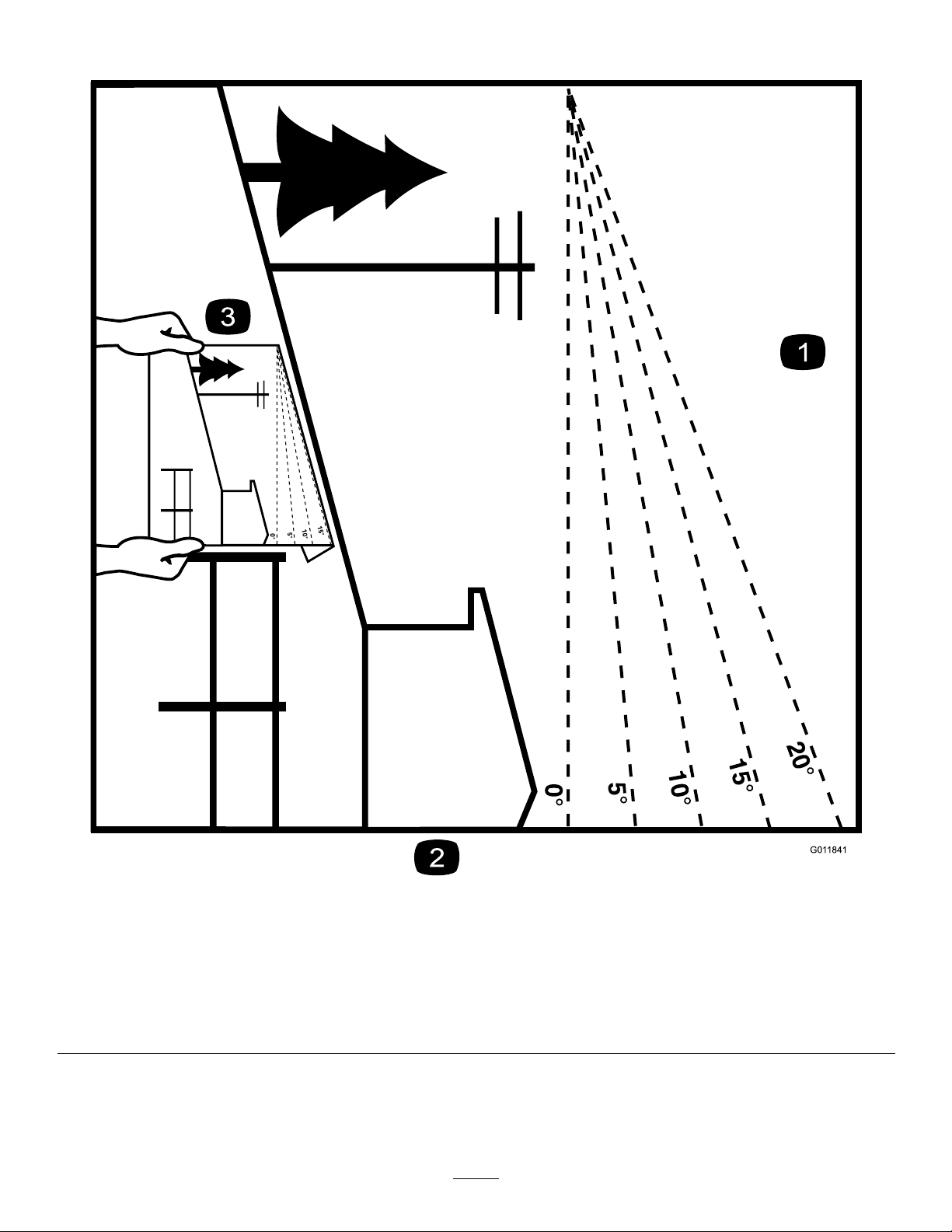
SlopeIndicator
Figure3
Thispagemaybecopiedforpersonaluse.
1.Themaximumslopeyoucansafelyoperatethemachineonis15°.Usetheslopecharttodeterminethedegreeofslopeofhills
beforeoperating.Donotoperatethismachineonaslopegreaterthan15°.Foldalongtheappropriatelinetomatchthe
recommendedslope.
2.Alignthisedgewithaverticalsurface,atree,building,fencepole,etc.
3.Exampleofhowtocompareslopewithfoldededge.
5
g011841
Page 6
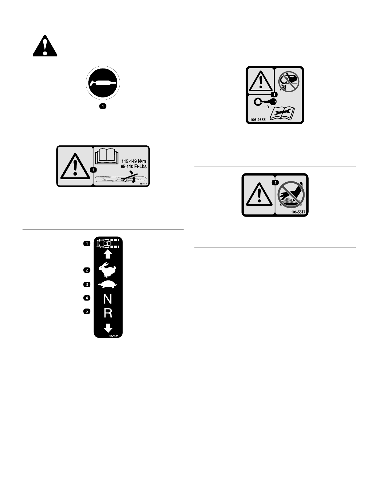
SafetyandInstructionalDecals
Safetydecalsandinstructionsareeasilyvisibletotheoperatorandarelocatednearanyarea
ofpotentialdanger.Replaceanydecalthatisdamagedorlost.
58-6520
1.Grease
93-7818
decal58-6520
decal106-2655
106-2655
1.Warning-donottouchorapproachmovingbelts;remove
theignitionkeyandreadtheinstructionsbeforeservicing
orperformingmaintenance.
decal93-7818
1.Warning—readtheOperator'sManualforinstructionson
torquingthebladebolt/nutto1 15to149N∙m(85to110
ft-lb).
99-8936
1.Machinespeed4.Neutral
2.Fast5.Reverse
3.Slow
decal106-5517
106-5517
1.Warning—donottouchthehotsurface.
decal99-8936
6
Page 7
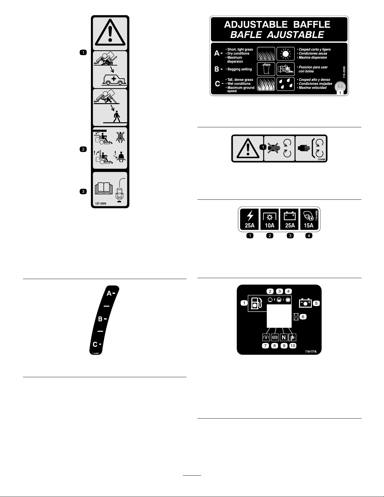
decal107-3069
107-3069
1.Warning–thereisnorolloverprotectionwhentherollbaris
down.
2.Toavoidinjuryordeathfromarolloveraccident,keepthe
rollbarintheraisedandlockedpositionandweartheseat
belt.Lowertherollbaronlywhenabsolutelynecessary;do
notweartheseatbeltwhentherollbarisdown.
3.ReadtheOperator'sManual;driveslowlyandcarefully.
decal110-2068
110-2068
1.ReadtheOperator'sManual.
decal112-9028
112-9028
1.Warning—stayawayfrommovingparts;keepallguardsin
place.
decal114-4466
114-4466
1.Main,25A
2.PTO,10A
3.Charge,25A
4.Auxiliary,15A
decal110-2067
110-2067
116-1716
decal116-1716
1.Fuel6.Hourmeter
2.Empty
3.Half
7.PTO
8.Parkingbrake
4.Full9.Neutral
5.Battery
10.Operatorpresenceswitch
7
Page 8
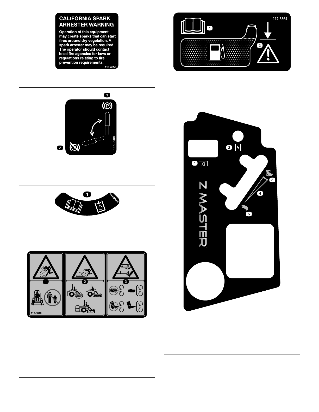
decal116-4858
116-4858
117-3864
decal117-3864
116-5988
1.Parkingbrake—engaged2.Parking
brake—disengaged
116-8726
1.ReadtheOperator’sManualforrecommendedhydraulic
uid.
1.ReadtheOperator’s
Manual.
2.Filltobottomofllerneck;
warning—donotoverll
thetank.
decal116-5988
decal116-8726
117-3848
1.Thrownobjecthazard—keepbystandersasafedistance
fromthemachine
2.Thrownobjecthazard,mower-donotoperatewithoutthe
deector,dischargecoverorgrasscollectionsystemin
place.
3.Cutting/dismembermentofhandorfoot—stayawayfrom
movingparts;keepallguardsandshieldsinplace.
decal121-7551
decal117-3848
121-7551
1.PowerT ake-off(PTO)4.Continuousvariable
setting
2.Choke5.Slow
3.Fast
8
Page 9
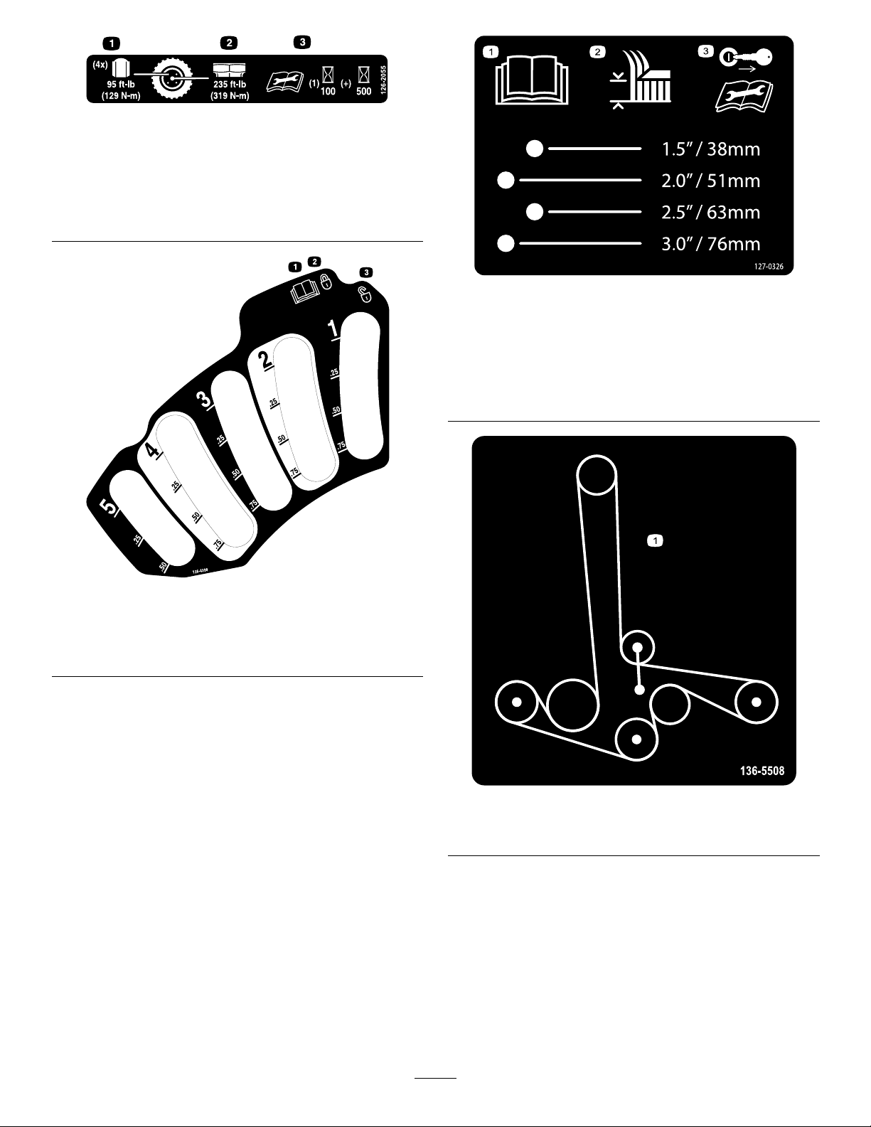
126-2055
1.Wheellugnuttorque129N∙m(95ft-lb)(4x)
2.Wheelhubnuttorque319N∙m(235ft-lb)
3.ReadandunderstandtheOperator’sManualbefore
performinganymaintenance,checktorqueafterrst100
hoursthenevery500hoursthereafter.
decal126-2055
decal127-0326
127-0326
1.ReadtheOperator’s
Manual
2.Lock
1.ReadtheOperator's
Manual.
3.Removethekeyfrom
theignitionandreadthe
Operator'sManualbefore
performingmaintenance
orservicingthemachine.
2.Height-of-cut
decal126-4398
126-4398
3.Unlock
decal136-5508
136-5508
1.Beltrouting
9
Page 10
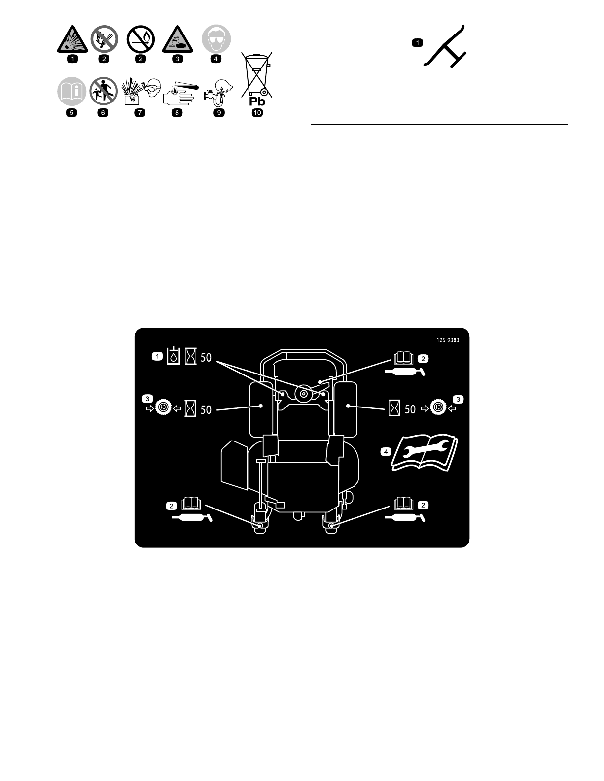
BatterySymbols
Someorallofthesesymbolsareonyourbattery
decaloemmarkt
Manufacturer'sMark
1.Indicatesthebladeisidentiedasapartfromtheoriginal
machinemanufacturer.
decalbatterysymbols
1.Explosionhazard
2.Nore,opename,or
6.Keepbystandersasafe
7.Weareyeprotection;
smoking
3.Causticliquid/chemical
8.Batteryacidcancause
burnhazard
4.Weareyeprotection.9.Flusheyesimmediately
5.ReadtheOperator's
10.Containslead;donot
Manual.
distanceawayfromthe
battery.
explosivegasescan
causeblindnessandother
injuries.
blindnessorsevereburns.
withwaterandgetmedical
helpfast.
discard
125–9383
1.Checkhydraulicoilevery50operatinghours.3.Checkthetirepressureevery50operatinghours.
2.ReadtheOperator’sManualforinformationonlubricating
themachine.
4.ReadtheOperator’sManualbeforeservicingorperforming
maintenance.
10
decal125-9383
Page 11
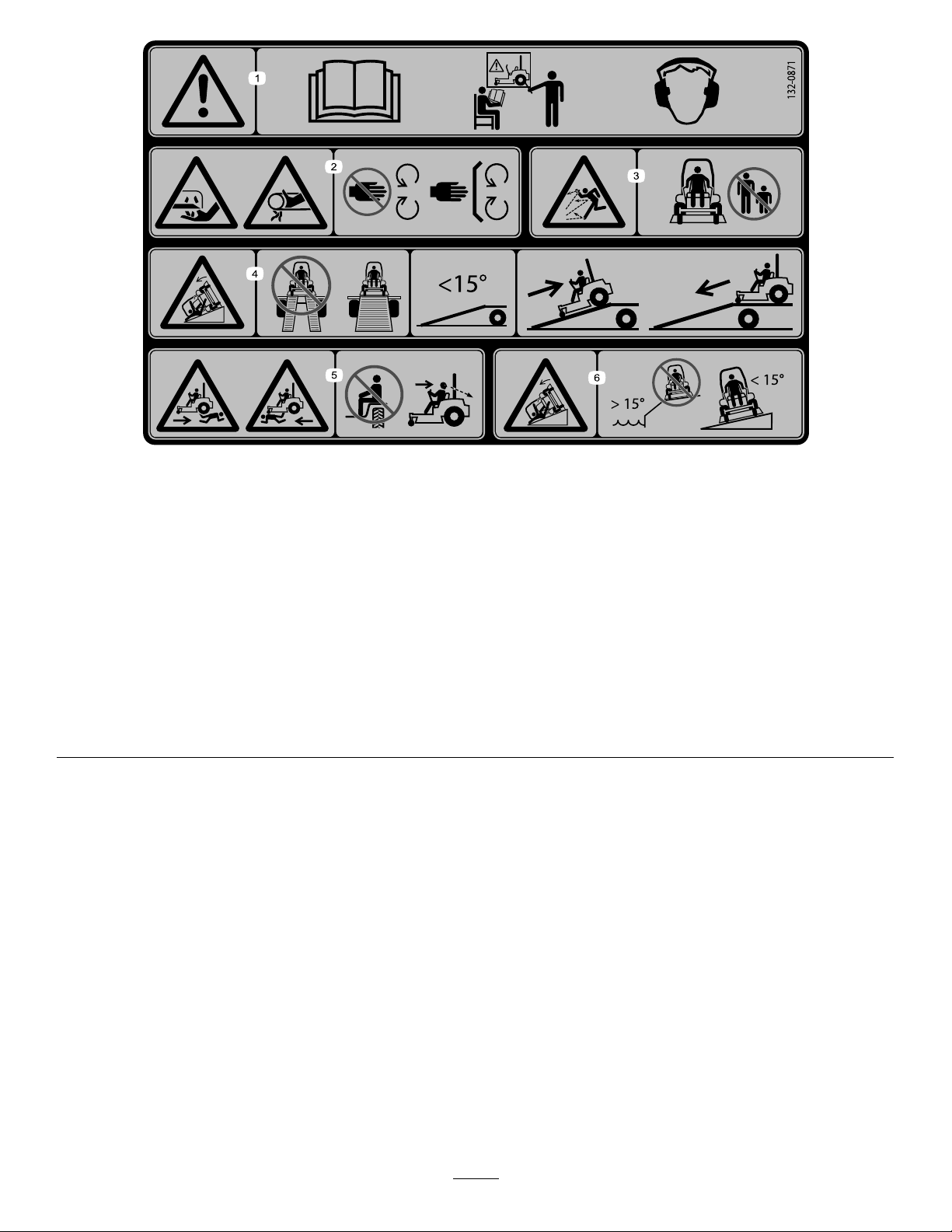
132-0871
Note:Thismachinecomplieswiththeindustrystandardstabilitytestinthestaticlateralandlongitudinaltestswiththemaximum
recommendedslopeindicatedonthedecal.ReviewtheinstructionsforoperatingthemachineonslopesintheOperator’sManualas
wellastheconditionsinwhichyouwouldoperatethemachinetodeterminewhetheryoucanoperatethemachineinthoseconditions
onthatdayandatthatsite.Changesintheterraincanresultinachangeinslopeoperationforthemachine.Ifpossible,keepthe
cuttingunitsloweredtothegroundwhileoperatingthemachineonslopes.Raisingthecuttingunitswhileoperatingonslopescan
causethemachinetobecomeunstable.
decal132-0871
1.Warning—readtheOperator’sManual;donotoperatethis
machineunlessyouaretrained;wearhearingprotection.
2.Cutting,dismembering,andentanglementhazard—keep
handsawayfrommovingparts;keepallguardsandshieldsin
place.
3.Thrownobjecthazard—keepbystandersaway.6.Tippinghazardonslopes—donotuseonslopesnearopen
4.Ramphazard—whenloadingontoatrailer ,donotusedual
ramps;onlyuseasingularrampwideenoughforthemachine
andthathasaninclinelessthan15°;backuptheramp(in
reverse)anddriveforwardofftheramp.
5.Bodilyharmhazard—donotcarrypassengers;lookbehind
youwhenmowinginreverse.
water;donotuseonslopesgreaterthan15°.
11
Page 12
ProductOverview
HourMeter
Thehourmeterrecordsthenumberofhoursthe
enginehasoperated.Itoperateswhentheengine
isrunning.Usethesetimesforschedulingregular
maintenance(Figure6).
FuelGauge
Thefuelgaugeislocatedwiththehourmeter,and
thebarslightupwhentheignitionswitchisintheON
position(Figure6).
Theindicatorlightappearswhenthefuellevelislow
(approximately1gallonremaininginthefueltank).
Safety-InterlockIndicators
Figure4
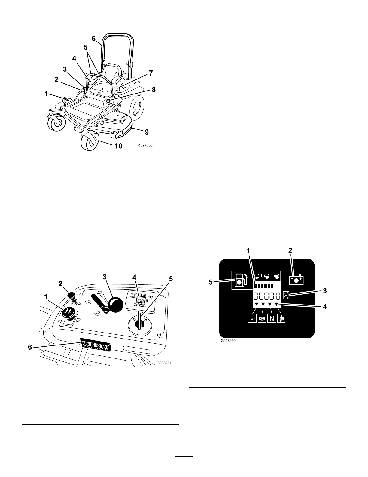
1.Height-of-cutdecklift
pedal
2.Transportlock
3.Parking-brakelever8.Fuelcap
4.Controls
5.Motion-controllevers
6.Rollbar
7.Seatbelt
9.Mowerdeck
10.Casterwheel
Controls
Becomefamiliarwithallthecontrolsbeforeyoustart
theengineandoperatethemachine(Figure4and
Figure5).
g027333
Therearesymbolsonthehourmeterthatindicate
withablacktrianglethattheinterlockcomponentis
positionedcorrectly(Figure6).
Battery-IndicatorLight
IfyouturntheignitionkeytotheONpositionfora
fewseconds,thebatteryvoltagedisplaysinthearea
wherethehoursarenormallydisplayed.
Thebatterylightturnsonwhentheignitionisturned
onandwhenthechargeisbelowthecorrectoperating
level(Figure6).
Figure5
1.PTOswitch
2.Chokecontrol
3.Throttlecontrol6.Fuses
4.Hour
5.Ignitionswitch
g008950
Figure6
1.Fuelgauge(bars)4.Safety-interlocksymbols
g008951
meter/safety-interlock
display
2.Batterylight
3.Hourmeter
5.Lowfuel-indicatorlight
ThrottleControl
Thethrottlecontrolstheenginespeed,andithasa
continuous-variablesettingfromtheSLOWtoFAST
position(Figure5).
12
Page 13

ChokeControl
Specications
Usethechoketostartacoldengine.Pullthechoke
knobuptoengageit.Pushthechokeknobdownto
disengageit(Figure5).
Blade-ControlSwitch(Power
Takeoff)
Theblade-controlswitch(PTO)engagesand
disengagespowertothemowerblades(Figure5).
IgnitionSwitch
Usethisswitchtostartthemowerengine.Ithas3
positions:START,RUN,andOFF.
Motion-ControlLevers
Usethemotion-controlleverstodrivethemachine
forward,reverse,andturneitherdirection.
Neutral-LockPosition
Note:Specicationsanddesignaresubjectto
changewithoutnotice.
Width:
Withoutdeck
Deector—up156.8cm(61.7inches)
Deector—down192.2cm(75.7inches)
Length:
Rollbar—up
Rollbar—down
Height:
Rollbar—upRollbar—down
179.1cm(70.5inches)118.9cm(46.8inches)
Weight:
ModelWeight
74950
134.6cm(53.0inches)
211.1cm(83.1inches)
215.4cm(84.8inches)
541kg(1,193lb)
UsetheNEUTRAL-LOCKpositionwiththe
safety-interlocksystemtoengageandtodetermine
theNEUTRALposition.
Fuel-ShutoffValve
Closethefuel-shutoffvalve(undertheseat)when
transportingorstoringthemower.
Attachments/Accessories
AselectionofT oroapprovedattachmentsand
accessoriesisavailableforusewiththemachineto
enhanceandexpanditscapabilities.Contactyour
AuthorizedServiceDealerorDistributororgoto
www.T oro.comforalistofallapprovedattachments
andaccessories.
13
Page 14

Operation
containersontheground,awayfromyourvehicle
beforelling.
Note:Determinetheleftandrightsidesofthe
machinefromthenormaloperatingposition.
BeforeOperation
BeforeOperationSafety
GeneralSafety
•Neverallowchildrenoruntrainedpeopleto
operateorservicethemachine.Localregulations
mayrestricttheageoftheoperator.Theowner
isresponsiblefortrainingalloperatorsand
mechanics.
•Becomefamiliarwiththesafeoperationofthe
equipment,operatorcontrols,andsafetysigns.
•Knowhowtostopthemachineandshutoffthe
enginequickly.
•Checkthatoperator-presencecontrols,safety
switches,andshieldsareattachedandfunctioning
properly.Donotoperatethemachineunlessthey
arefunctioningproperly.
•Beforemowing,alwaysinspectthemachineto
ensurethattheblades,bladebolts,andcutting
assembliesareingoodworkingcondition.
Replacewornordamagedbladesandboltsinsets
topreservebalance.
•Inspecttheareawhereyouwillusethemachine
andremoveallobjectsthatthemachinecould
throw.
•Evaluatetheterraintodeterminetheappropriate
equipmentandanyattachmentsoraccessories
requiredtooperatethemachineproperlyand
safely.
FuelSafety
•Toavoidpersonalinjuryorpropertydamage,use
extremecareinhandlingfuel.Fuelvaporsare
ammableandexplosive.
•Extinguishallcigarettes,cigars,pipes,andother
sourcesofignition.
•Useonlyanapprovedfuelcontainer.
•Donotremovethefuelcaporaddfueltothefuel
tankwhiletheengineisrunningorwhilehot.
•Donotrefuelthemachineindoors.
•Donotstorethemachineorfuelcontainerwhere
thereisanopename,spark,orpilotlight,such
asonawaterheateroronotherappliances.
•Donotllcontainersinsideavehicleoronatruck
ortrailerbedwithaplasticliner.Alwaysplace
•Removetheequipmentfromthetruckortrailer
andrefuelitwhileitisontheground.Ifthisisnot
possible,thenrefuelfromaportablecontainer
ratherthanafuel-dispensernozzle.
•Donotoperatethemachinewithouttheentire
exhaustsysteminplaceandinproperworking
condition.
•Keepthefuel-dispensernozzleincontactwith
therimofthefueltankorcontaineropeningat
alltimesuntilfuelingiscomplete.Donotusea
nozzlelock-opendevice.
•Ifyouspillfuelonyourclothing,changeyour
clothingimmediately.Wipeupanyfuelthatspills.
•Neveroverllthefueltank.Replacethefuelcap
andtightenitsecurely.
•Storefuelinanapprovedcontainerandkeepit
outofthereachofchildren.Neverbuymorethan
a30-daysupplyoffuel.
•Donotllthefueltankcompletelyfull.Addfuelto
thefueltankuntilthelevelis6to13mm(1/4to
1/2inch)belowthebottomofthellerneck.This
emptyspaceinthetankallowsfueltoexpand.
–Avoidprolongedbreathingofvapors.
–Keepyourfaceawayfromthenozzleandfuel
tankopening.
–Avoidcontactwithskin;washoffspillswith
soapandwater.
RecommendedFuel
•Forbestresults,useonlyclean,fresh(lessthan
30daysold),unleadedgasolinewithanoctane
ratingof87orhigher((R+M)/2ratingmethod).
•Ethanol:Gasolinewithupto10%ethanol
(gasohol)or15%MTBE(methyltertiarybutyl
ether)byvolumeisacceptable.Ethanoland
MTBEarenotthesame.Gasolinewith15%
ethanol(E15)byvolumeisnotapprovedforuse.
Neverusegasolinethatcontainsmorethan
10%ethanolbyvolume,suchasE15(contains
15%ethanol),E20(contains20%ethanol),orE85
(containsupto85%ethanol).Usingunapproved
gasolinemaycauseperformanceproblemsand/or
enginedamagewhichmaynotbecoveredunder
warranty.
•Donotusegasolinecontainingmethanol.
•Donotstorefueleitherinthefueltankorfuel
containersoverthewinterunlessyouuseafuel
stabilizer.
•Donotaddoiltogasoline.
14
Page 15
Using Stabilizer/Conditioner
Useafuelstabilizer/conditionerinthemachineto
providethefollowingbenets:
•Keepsfuelfreshduringstorageof90daysorless
(drainthefueltankwhenstoringthemachinefor
morethan90days)
•Cleanstheenginewhileitruns
•Eliminatesgum-likevarnishbuildupinthefuel
system,whichcauseshardstarting
Important:Donotusefueladditives
containingmethanolorethanol.
Addthecorrectamountoffuelstabilizer/conditioner
tothefuel.
Note:Afuelstabilizer/conditionerismost
effectivewhenmixedwithfreshfuel.Tominimize
thechanceofvarnishdepositsinthefuelsystem,
usefuelstabilizeratalltimes.
FillingtheFuelTank
1.Parkthemachineonlevelground.
2.Shutofftheengineandengagetheparking
brake.
3.Cleanaroundthefuel-tankcap.
4.Fillthefueltanktothebottomofthellerneck
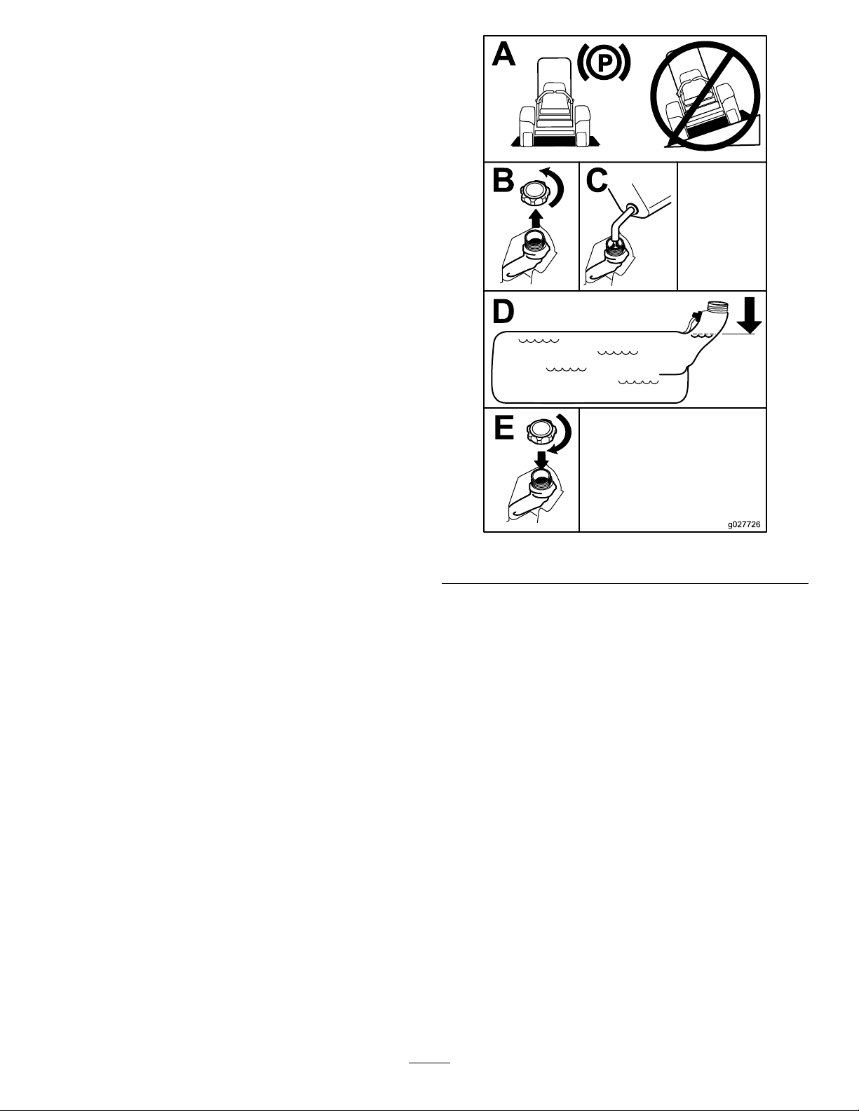
(Figure7).
Note:Donotllthefueltankcompletelyfull.
Theemptyspaceinthetankallowsthegasoline
toexpand.
g027726
Figure7
CheckingtheEngine-Oil Level
Beforeyoustarttheengineandusethemachine,
checktheoillevelintheenginecrankcase;referto
CheckingtheEngine-OilLevel(page15).
BreakinginaNewMachine
Newenginestaketimetodevelopfullpower.Mower
decksanddrivesystemshavehigherfrictionwhen
new,placingadditionalloadontheengine.Allow
40to50hoursofbreak-intimefornewmachinesto
developfullpowerandbestperformance.
15
Page 16
UsingtheRollover ProtectionSystem(ROPS)
WARNING
Toavoidinjuryordeathfromrollover:keep
therollbarinthefullyraisedlockedposition
andusetheseatbelt.
Ensurethattheseatissecuredtothe
machine.
WARNING
Thereisnorolloverprotectionwhentheroll
barisinthedownposition.
•Lowertherollbaronlywhenabsolutely
necessary.
•Donotweartheseatbeltwhentherollbar
isinthedownposition.
•Driveslowlyandcarefully.
•Raisetherollbarassoonasclearance
permits.
•Checkcarefullyforoverheadclearances
(i.e.,branches,doorways,electricalwires)
beforedrivingunderanyobjectsanddo
notcontactthem.
Important:Lowertherollbaronlywhen
absolutelynecessary.
Important:Ensurethattheseatissecuredto
themachine.
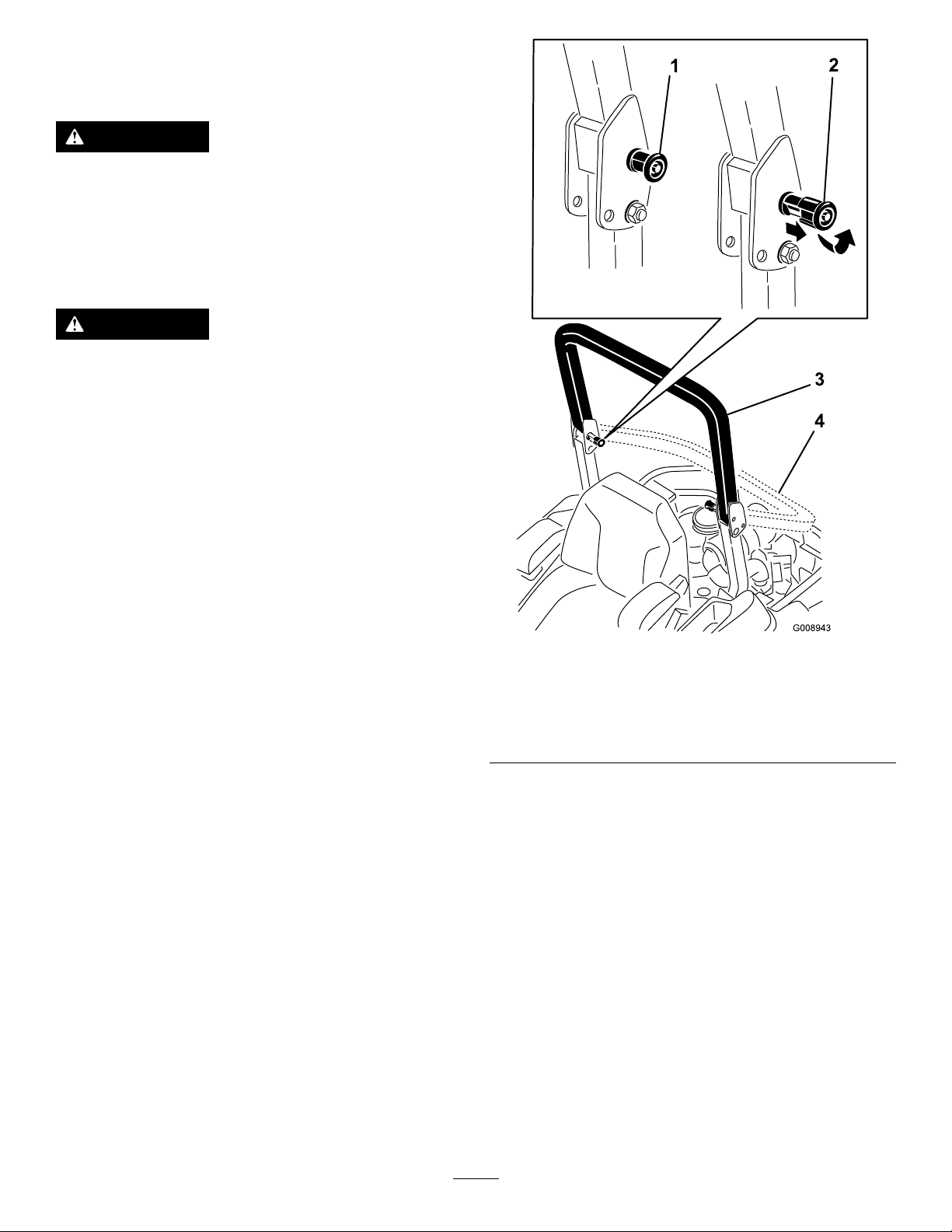
1.Tolowertherollbar,applyforwardpressureto
theupperpartoftherollbar.
2.Pullbothknobsoutandrotatethem90°sothey
arenotengaged(Figure8).
3.Lowertherollbartothedownposition(Figure
8).
Figure8
1.ROPSknob
2.PulltheROPSknobout
androtate90degrees
4.Toraisetherollbar,raisetherollbartothe
operateposition,rotatetheknobssothatthey
movepartiallyintothegrooves(Figure8).
5.Raisetherollbartothefulluprightpositionwhile
pushingontheupperrollbarandthepinssnap
intopositionwhentheholesalignwiththepins
(Figure8).
3.Rollbarintheupright
position
4.Rollbarinthefolded
position
Important:Alwaysusetheseatbeltwiththe
rollbarintheraisedposition.
6.Pushontherollbarandensurethatbothpins
areengaged.
g008943
ThinkSafetyFirst
Pleasereadallsafetyinstructionsandsymbolsinthe
safetysection.Knowingthisinformationcouldhelp
youorbystandersavoidinjury.
16
Page 17
DANGER
CAUTION
Operatingthemachineonwetgrassorsteep
slopescancauseslidingandlossofcontrol.
•Donotoperateonslopesgreaterthan15
degrees.
•Reducespeedanduseextremecautionon
slopes.
•Donotoperatethemachinenearwater.
DANGER
Wheelsdroppingoveredgescancause
rollovers,whichmayresultinseriousinjury,
death,ordrowning.
Donotoperatethemachineneardrop-offs.
DANGER
Operatingthemachinewhiletherollbaris
downmayleadtoseriousinjuryordeathin
theeventofarollover.
Alwayskeeptherollbarinthefullyraisedand
lockedpositionandusetheseatbelt.
Thismachineproducessoundlevelsin
excessof85dBAattheoperator’searand
cancausehearinglossthroughextended
periodsofexposure.
Wearhearingprotectionwhenoperatingthis
machine.
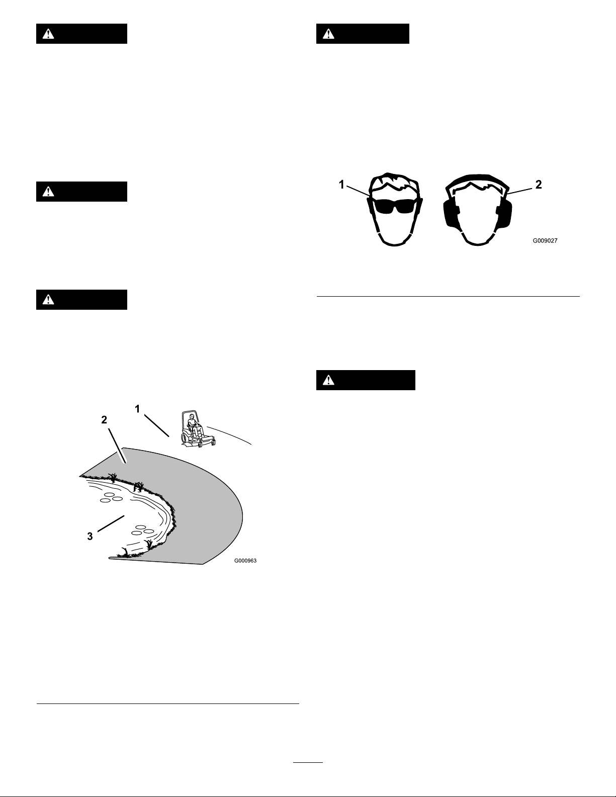
Useprotectiveequipmentforyoureyes,ears,hands,
feet,andhead.
g009027
Figure10
1.Weareyeprotection.2.Wearhearingprotection.
UsingtheSafety-Interlock System
WARNING
1.SafeZone—usethe
machinehereonslopes
lessthan15degreesor
atareas.
2.DangerZone—usea
walk-behindmowerand/or
ahandtrimmeronslopes
greaterthan15degrees
andneardrop-offsor
water.
Figure9
3.Water
Ifsafety-interlockswitchesaredisconnected
ordamaged,themachinecouldoperate
unexpectedlycausingpersonalinjury.
•Donottamperwiththeinterlockswitches.
•Checktheoperationoftheinterlock
switchesdaily,andreplaceanydamaged
switchesbeforeoperatingthemachine.
Understandingthe Safety-InterlockSystem
Thesafety-interlocksystemisdesignedtopreventthe
g000963
enginefromstartingunless:
•Theparkingbrakeisengaged.
•Theblade-controlswitch(PTO)isdisengaged.
•Themotion-controlleversareintheNEUTRAL-LOCK
position.
Thesafety-interlocksystemalsoisdesignedtoshutoff
theenginewhenthetractioncontrolsaremovedfrom
thelockedpositionwiththeparkingbrakeengagedor
ifyourisefromtheseatwhenthePTOisengaged.
Thehourmeterhassymbolstonotifytheuserwhen
theinterlockcomponentisinthecorrectposition.
Whenthecomponentisinthecorrectposition,a
trianglelightsupinthecorrespondingsquare.
17
Page 18
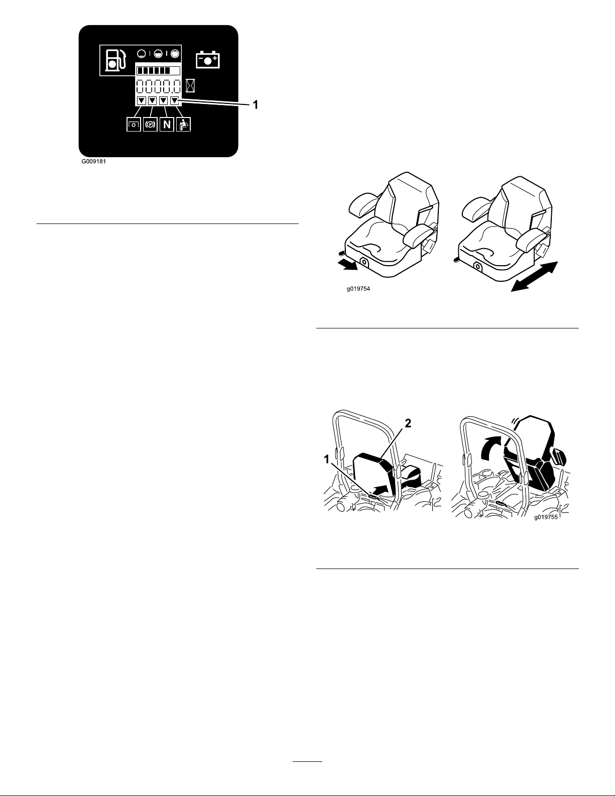
Figure11
1.Triangleslightupwhentheinterlockcomponentsareinthe
correctposition
TestingtheSafety-Interlock System
totheNEUTRAL-LOCKposition.Trystartingthe
engine;theengineshouldnotstart.
PositioningtheSeat
Theseatmovesforwardandbackward.Positionthe
seatwhereyouhavethebestcontrolofthemachine
andaremostcomfortable.
Toadjust,movetheleversidewaystounlocktheseat
(Figure12).
g009181
ServiceInterval:Beforeeachuseordaily
Testthesafety-interlocksystembeforeyouusethe
machineeachtime.Ifthesafetysystemdoesnot
operateasdescribedbelow,haveanAuthorized
ServiceDealerrepairthesafetysystemimmediately .
1.Sittingontheseat,engagetheparkingbrake
andmovetheblade-controlswitch(PTO)tothe
ONposition.Trystartingtheengine;theengine
shouldnotstart.
2.Sittingontheseat,engagetheparkingbrake
andmovetheblade-controlswitch(PTO)tothe
OFFposition.Moveeithermotion-controllever
(outoftheNEUTRAL-LOCKposition).Trystarting
theengine;theengineshouldnotstart.Repeat
fortheothercontrollever.
3.Sittingontheseat,engagetheparkingbrake,
movetheblade-controlswitch(PTO)totheOFF
position,andmovethemotion-controllevers
totheNEUTRAL-LOCKposition.Nowstartthe
engine.Whiletheengineisrunning,disengage
theparkingbrake,engagetheblade-control
switch(PTO),andriseslightlyfromtheseat;the
engineshouldshutoff.
g019754
Figure12
UnlatchingtheSeat
Tounlatchtheseat,pushtheseatlatchforward
(Figure13).
g019755
Figure13
1.Seatlatch2.Seat
4.Sittingontheseat,engagetheparkingbrake,
movetheblade-controlswitch(PTO)totheOFF
position,andmovethemotion-controllevers
totheNEUTRAL-LOCKposition.Nowstartthe
engine.Whiletheengineisrunning,center
eithermotioncontrolandmove(forwardor
reverse);theengineshouldshutoff.Repeatfor
othermotioncontrol.
5.Sittingontheseat,disengagetheparkingbrake,
movetheblade-controlswitch(PTO)totheOFF
position,andmovethemotion-controllevers
ChangingtheSeat Suspension
Theseatadjuststoprovideasmoothandcomfortable
ride.Positiontheseatwhereyouaremost
comfortable.
Toadjust,turntheknobinfronteitherdirectionto
providethebestcomfort(Figure14).
18
Page 19

overifawheelgoesovertheedgeoriftheedge
givesway.
•Stopthebladeswheneveryouarenotmowing.
•Stopthemachineandinspectthebladesafter
strikinganobjectorifthereisanabnormal
vibrationinthemachine.Makeallnecessary
repairsbeforeresumingoperation.
•Slowdownandusecautionwhenmakingturns
andcrossingroadsandsidewalkswiththe
machine.Alwaysyieldtheright-of-way.
Figure14
1.Seat-suspensionknob
DuringOperation
DuringOperationSafety
GeneralSafety
•Theowner/operatorcanpreventandisresponsible
foraccidentsthatmaycausepersonalinjuryor
propertydamage.
•Wearappropriateclothing,includingeye
protection;slip-resistant,substantialfootwear;and
hearingprotection.Tiebacklonghairanddonot
wearjewelry.
•Donotoperatethemachinewhileill,tired,or
undertheinuenceofalcoholordrugs.
•Nevercarrypassengersonthemachineandkeep
bystandersandpetsawayfromthemachine
duringoperation.
•Operatethemachineonlyingoodvisibilitytoavoid
holesorhiddenhazards.
•Avoidmowingonwetgrass.Reducedtraction
couldcausethemachinetoslide.
•Ensurethatalldrivesareinneutral,theparking
brakeisengaged,andyouareintheoperating
positionbeforeyoustarttheengine.
•Keepyourhandsandfeetawayfromthecutting
units.Keepclearofthedischargeopeningatall
times.
•Lookbehindanddownbeforebackinguptobe
sureofaclearpath.
•Usecarewhenapproachingblindcorners,shrubs,
trees,orotherobjectsthatmayobscureyour
vision.
•Donotmowneardrop-offs,ditches,or
embankments.Themachinecouldsuddenlyroll
g019768
•Disengagethedrivetothecuttingunitandshut
offtheenginebeforeadjustingtheheightof
cut(unlessyoucanadjustitfromtheoperating
position).
•Neverrunanengineinanareawhereexhaust
gasesareenclosed.
•Neverleavearunningmachineunattended.
•Beforeleavingtheoperatingposition(including
toemptythecatchersortounclogthechute),do
thefollowing:
–Stopthemachineonlevelground.
–Disengagethepowertake-offandlowerthe
attachments.
–Engagetheparkingbrake.
–Shutofftheengineandremovethekey.
–Waitforallmovingpartstostop.
•Donotoperatethemachinewhenthereistherisk
oflightning.
•Donotusethemachineasatowingvehicle.
•Donotchangethegovernorspeedoroverspeed
theengine.
•Useaccessoriesandattachmentsapprovedby
Toroonly.
RolloverProtectionSystem (ROPS)Safety
•Donotremovetherollbarfromthemachine.
•Ensurethattheseatbeltisattachedandthatyou
canreleaseitquicklyinanemergency.
•Alwayswearyourseatbeltwhentherollbarisup.
•Checkcarefullyforoverheadobstructionsanddo
notcontactthem.
•Keeptherollbarinsafeoperatingconditionby
thoroughlyinspectingitperiodicallyfordamage
andkeepingallthemountingfastenerstight.
•Replaceadamagedrollbar.Donotrepairoralter
it.
19
Page 20
SlopeSafety
•Slowdownthemachineanduseextracareon
hillsides.Travelupanddownonhillsides.Turf
conditionscanaffectthestabilityofthemachine.
•Avoidturningthemachineonslopes.Ifyoumust
turnthemachine,turnitslowlyandgradually
downhill,ifpossible.
•Donotturnthemachinesharply.Usecarewhen
reversingthemachine.
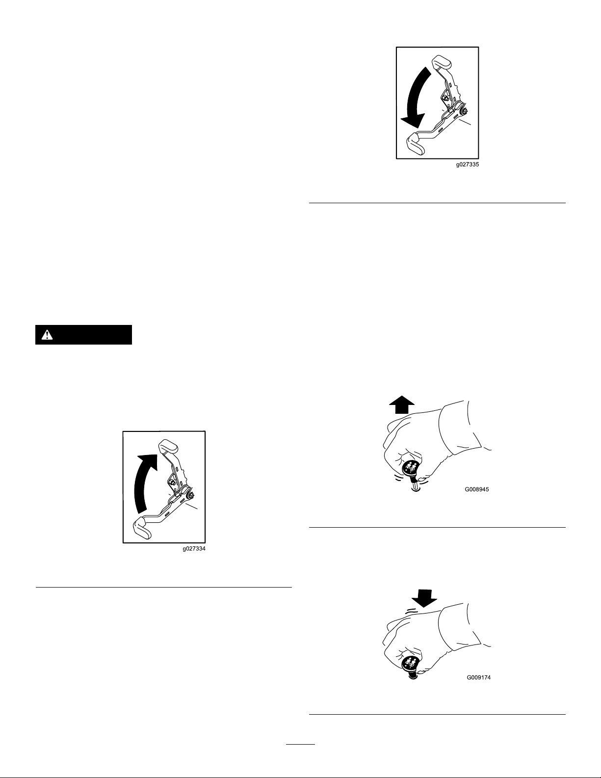
DisengagingtheParkingBrake
•Useextracarewhileoperatingthemachinewith
attachments;theycanaffectthestabilityofthe
machine.
OperatingtheParking Brake
Alwaysengagetheparkingbrakewhenyoustopthe
machineorleaveitunattended.
EngagingtheParkingBrake
WARNING
Theparkingbrakemaynotholdthemachine
parkedonaslopeandcouldcausepersonal
injuryorpropertydamage.
Donotparkonslopesunlessthewheelsare
chockedorblocked.
g027335
Figure16
OperatingtheMower Blade-ControlSwitch(PTO)
Theblade-controlswitch(PTO)startsandstopsthe
mowerbladesandanypoweredattachments.
EngagingtheBlade-Control Switch(PTO)
Note:Engagingtheblade-controlswitch(PTO)with
thethrottlepositionathalforlesscausesexcessive
weartothedrivebelts.
Figure15
g008945
Figure17
g027334
DisengagingtheBlade-Control Switch(PTO)
g009174
Figure18
20
Page 21
OperatingtheThrottle
OperatingtheIgnition
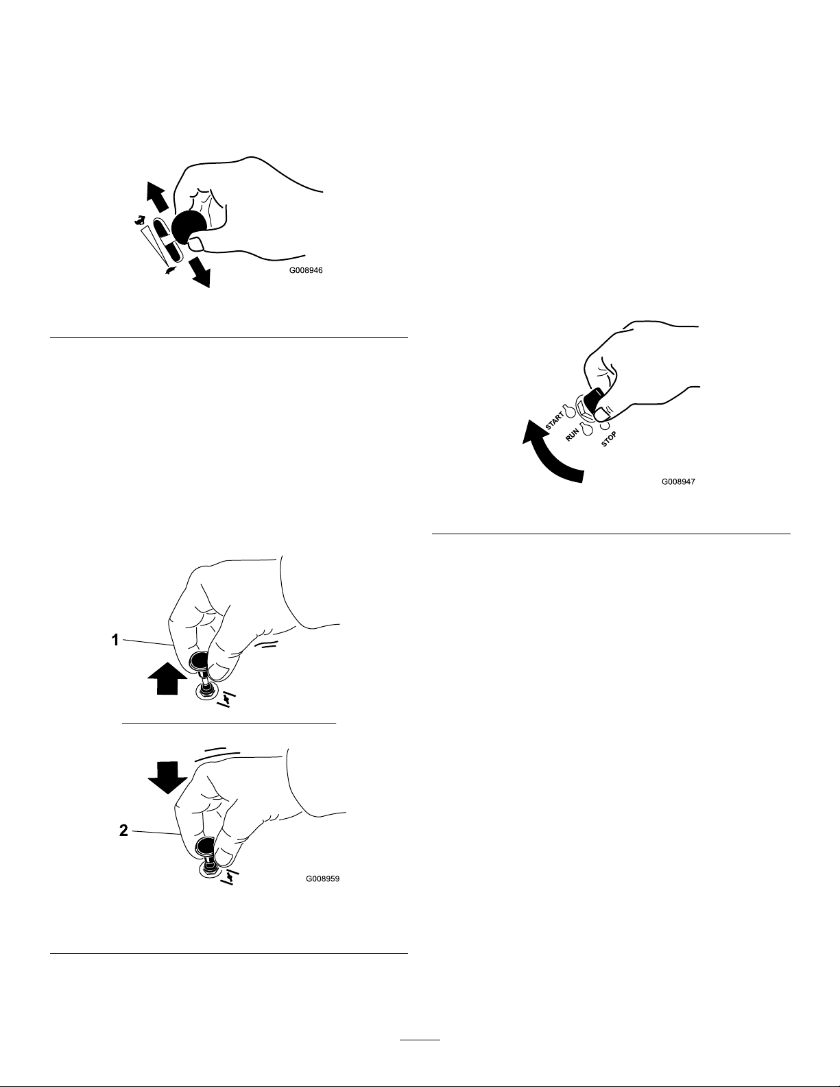
YoucanmovethethrottlecontrolbetweentheFAST
andSLOWpositions(Figure19).
AlwaysusetheFASTpositionwhenturningonthe
mowerdeckwiththeblade-controlswitch(PTO).
Figure19
OperatingtheChoke
Usethechoketostartacoldengine.
1.Iftheengineiscold,usethechoketostartthe
engine.
Switch
1.TurntheignitionkeytotheSTARTposition
(Figure21).
Note:Whentheenginesstarts,releasethekey .
Important:Donotengagestarterformore
than5secondsatatime.Iftheenginefails
tostartallowa15secondcool-downperiod
betweenattempts.Failuretofollowthese
instructionscanburnoutthestartermotor.
Note:Youmayneedmultipleattemptstostart
g008946
theenginewhenyoustartitthersttimeafter
thefuelsystemhasbeenwithoutfuelcompletely.
2.Pulluponthechokeknobtoengagethechoke
beforeusingtheignitionswitch(Figure20).
3.Pushdownonthechoketodisengagethechoke
aftertheenginehasstarted(Figure20).
Figure20
g008947
Figure21
2.Turntheignitionkeytoshutofftheengine.
StartingandShuttingOff theEngine
StartingtheEngine
1.RaisetheROPSupandlockintoplace,siton
theseat,andfastentheseatbelt.
2.MovethemotioncontrolstotheNEUTRAL-LOCK
position.
3.Engagetheparkingbrake;refertoEngagingthe
ParkingBrake(page20).
4.Movetheblade-controlswitch(PTO)totheOFF
position(Figure22).
5.Movethethrottlelevermidwaybetweenthe
g008959
SLOWandFASTpositions.
1.Onposition2.Offposition
21
Page 22
ShuttingOfftheEngine
CAUTION
Childrenorbystandersmaybeinjuredifthey
moveorattempttooperatethemachinewhile
itisunattended.
Alwaysremovetheignitionkeyandengage
theparkingbrakewhenleavingthemachine
unattended,evenifjustforafewminutes.
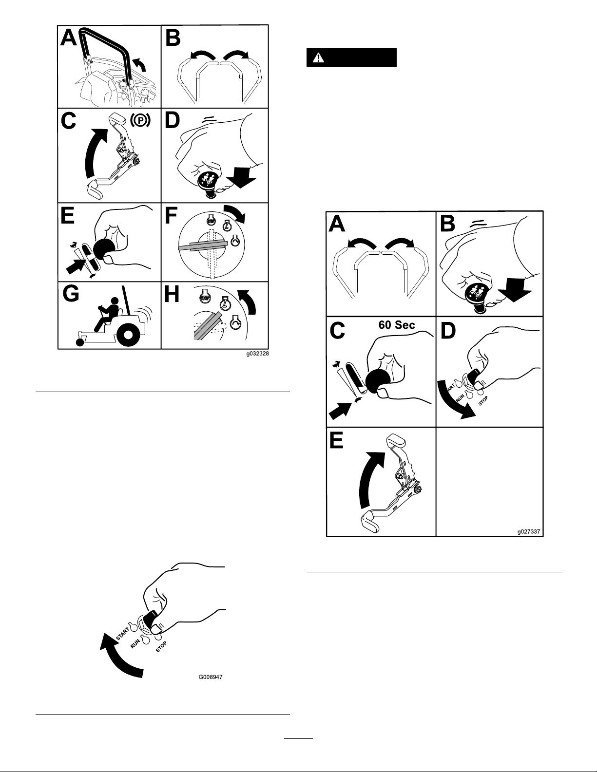
Lettheengineidleatslowthrottle(turtle)for60
secondsbeforeturningtheignitionswitchtotheOFF
position.
Figure22
6.TurntheignitionkeytotheSTARTposition
(Figure23).
Note:Whentheenginesstarts,releasethekey .
Important:Donotengagestarterformore
than5secondsatatime.Iftheenginefails
tostartallowa15-secondcool-downperiod
betweenattempts.Failuretofollowthese
instructionscanburnoutthestartermotor.
Note:Additionalstartingcyclesmaybe
requiredwhenstartingtheenginefortherst
timeafterthefuelsystemhasbeenwithoutfuel
completely.
g032328
g027337
Figure24
Important:Makesurethatthefuel-shutoffvalve
isclosedbeforetransportingorstoringthe
machine,asfuelleakagemayoccur.Engagethe
parkingbrakebeforetransporting.Makesurethat
youremovethekeyasthefuelpumpmayrunand
causethebatterytolosecharge.
Figure23
g008947
22
Page 23
UsingtheMotion-Control
CAUTION
Levers
Machinecanspinveryrapidly.Operatormay
losecontrolofmachineandcausepersonal
injuryordamagetomachine.
•Usecautionwhenmakingturns.
•Slowthemachinedownbeforemaking
sharpturns.
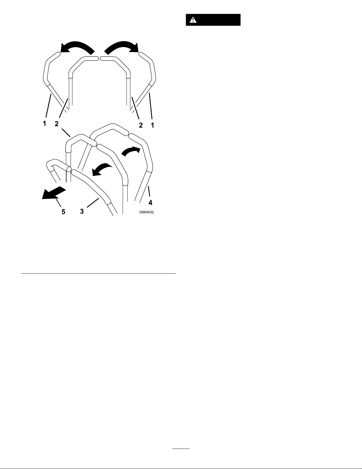
Figure25
1.Motion-control
lever—NEUTRAL-LOCK
position
2.Center,unlockedposition5.Frontofmachine
3.Forward
4.Backward
DrivingtheMachine
Thedrivewheelsturnindependently,poweredby
hydraulicmotorsoneachaxle.Y oucanturn1side
inreversewhileyouturntheotherforward,causing
themachinetospinratherthanturn.Thisgreatly
improvesthemachinemaneuverabilitybutmay
requiresometimeforyoutoadapttohowitmoves.
Thethrottlecontrolregulatestheenginespeedas
measuredinrpm(revolutionsperminute).Place
thethrottlecontrolintheFASTpositionforbest
performance.Alwaysoperateinthefullthrottle
positionwhenmowing.
g004532
23
Page 24
DrivingForward
DrivingBackward
Note:Theenginestopswhenyoumovethe
traction-controlwiththeparkingbrakeengaged.
Tostop,pullthemotion-controlleverstotheNEUTRAL
position.
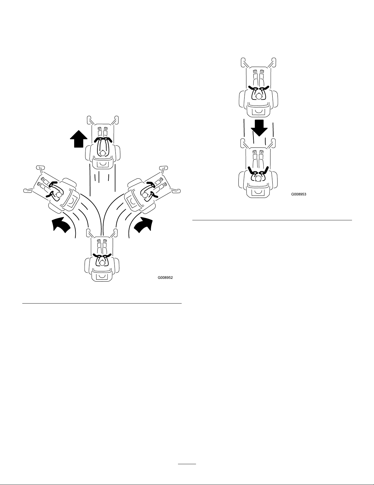
1.Disengagetheparkingbrake;referto
DisengagingtheParkingBrake(page20).
2.Movetheleverstothecenter,unlockedposition.
3.Togoforward,slowlypushthemotion-control
leversforward(Figure26).
1.Movetheleverstothecenter,unlockedposition.
2.Togobackward,slowlypullthemotion-control
leversrearward(Figure27).
g008953
Figure27
Figure26
g008952
24
Page 25
StoppingtheMachine
AdjustingtheHeightofCut
Tostopthemachine,movethetraction-controllevers
toneutral,andthenmovethemtothelockedposition,
disengagetheblade-controlswitch(PTO),andturn
theignitionkeytotheOFFposition.
Engagetheparkingbrakewhenyouleavethe
machine;refertoEngagingtheParkingBrake(page
20).Remembertoremovethekeyfromtheignition
switch.
CAUTION
Childrenorbystandersmaybeinjuredifthey
moveorattempttooperatethemachinewhile
itisunattended.
Alwaysremovetheignitionkeyandengage
theparkingbrakewhenleavingthemachine
unattended,evenifjustforafewminutes.
UsingtheSideDischarge
Themowerhasahingedgrassdeectorthat
dispersesclippingstothesideanddowntowardthe
turf.
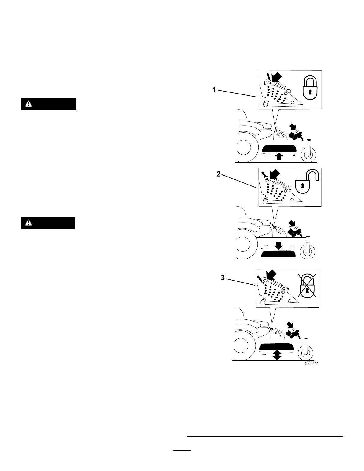
UsingtheTransportLock
Thetransportlockhas2positions,andisusedwith
thedeck-liftpedal.ThereisaLOCKpositionanda
UNLOCKpositionforthetransportposition(Figure28).
DANGER
Withoutagrassdeector,dischargecover,or
acompletegrass-catcherassemblymounted
inplace,youandothersareexposedtoblade
contactandthrowndebris.Contactwith
rotatingmowerblade(s)andthrowndebris
willcauseinjuryordeath.
•Neverremovethegrassdeectorfrom
themowerbecausethegrassdeector
routesmaterialdowntowardtheturf.Ifthe
grassdeectoriseverdamaged,replaceit
immediately.
•Neverputyourhandsorfeetunderthe
mower.
•Nevertrytoclearthedischargearea
ormowerbladesunlessyoumovethe
blade-controlswitch(PTO)totheOFF
position,rotatetheignitionkeytotheOFF
position,andremovethekey.
•Makesurethatthegrassdeectorisinthe
downposition.
g032377
Figure28
Transport-LockPositions
1.Transportlock3.UNLOCKposition—does
notlockthemowerdeck
intotransportposition
2.LOCKposition—mower
decklocksintotransport
position
25
Page 26
AdjustingtheHeight-of-CutPin
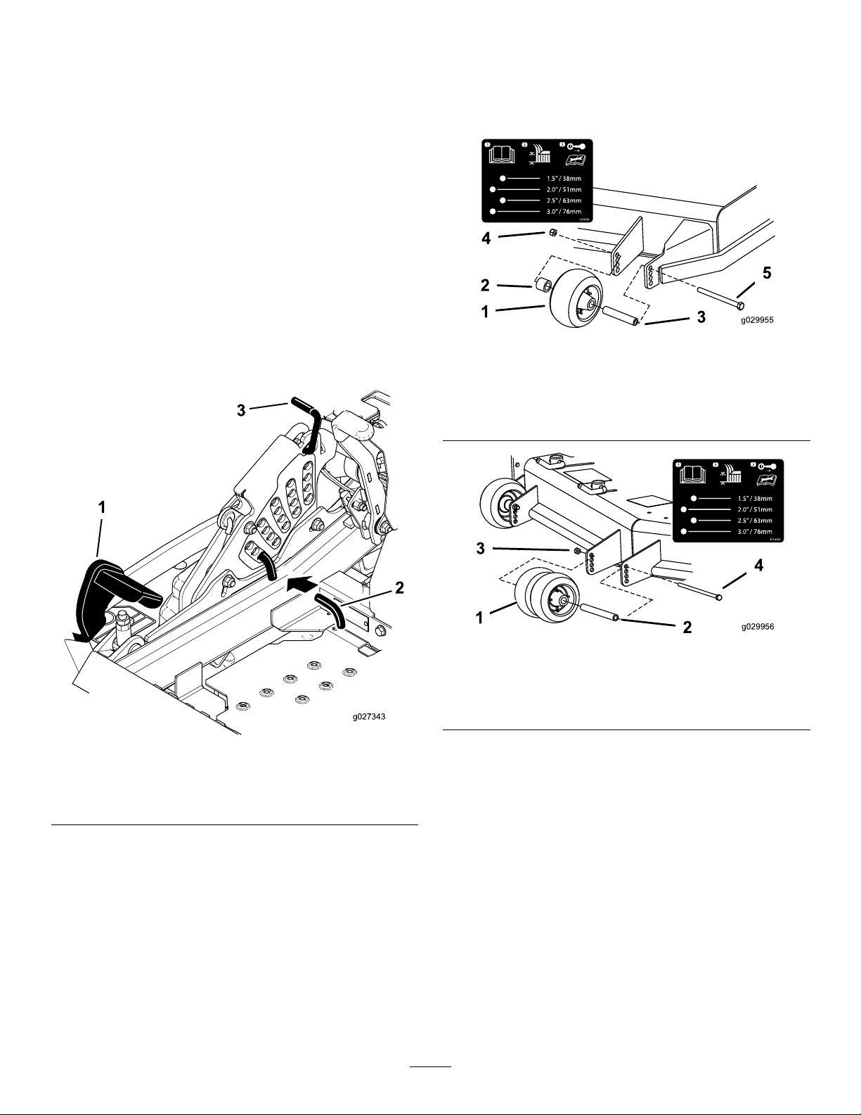
Theheight-of-cutisadjustedfrom25to140mm(1
to5-1/2inches)in6mm(1/4inch)incrementsby
relocatingtheclevispinintodifferentholelocations.
1.Movethetransportlocktothelockposition.
2.Pushonthedeck-liftpedalwithyourfoot,and
raisethemowerdecktothetransportposition
(alsothe140mm(5-1/2inches)cuttingheight
position)asshowninFigure29.
3.Toadjust,rotatethepin90degreesandremove
thepinfromtheheight-of-cutbracket(Figure
29).
4.Selectaholeintheheight-of-cutbracket
correspondingtotheheight-of-cutdesired,and
insertthepin(Figure29).
5.Pushonthedecklift,pullbackonthetransport
lock,andslowlylowerthemowerdeck.
2.Shutofftheengine,removethekey,andwait
forallmovingpartstostopbeforeleavingthe
operatingposition.
3.Adjusttheanti-scalprollersasshowninFigure
30,Figure31,andFigure32.
Figure30
1.Anti-scalproller4.Flangenut
2.Spacer
3.Bushing
5.Bolt
g029955
Figure29
1.Deck-liftpedal
2.Cut-of-heightpin
3.Transportlock
AdjustingtheAnti-Scalp Rollers
Wheneveryouchangetheheight-of-cut,itis
recommendedtoadjusttheheightoftheanti-scalp
rollers.
1.Disengagetheblade-controlswitch(PTO),move
themotion-controlleverstotheNEUTRAL-LOCK
position,andengagetheparkingbrake.
g029956
Figure31
1.Anti-scalproller3.Flangenut
2.Bushing4.Bolt
g027343
26
Page 27
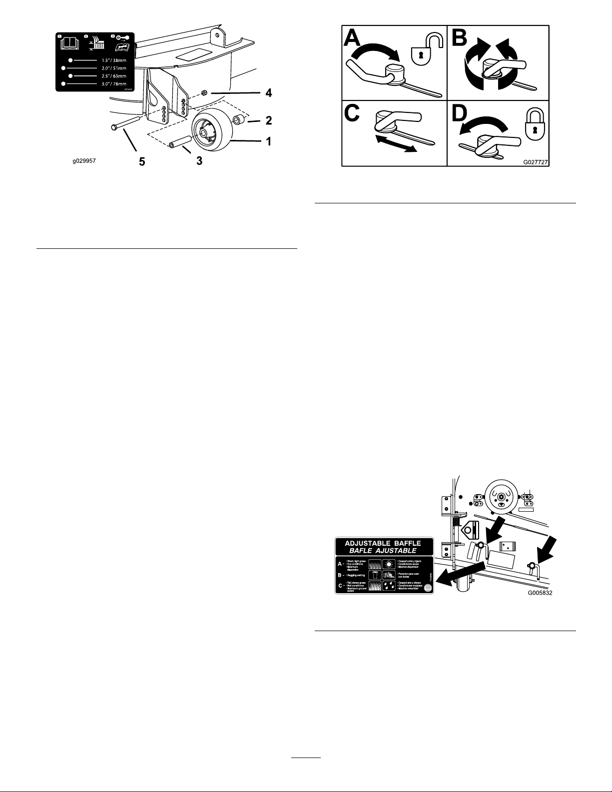
Figure32
1.Anti-scalproller4.Flangenut
2.Spacer
3.Bushing
5.Bolt
AdjustingtheFlowBafe
g029957
Figure33
g027727
PositioningtheFlowBafe
Thefollowingguresareonlyrecommendations
foruse.Adjustmentsvarybygrasstype,moisture
content,andtheheightofthegrass.
CamLocks
Thisprocedureisapplicableonlytomachineswiththe
ow-bafelocks.Certainmodelshavenutsandbolts
inplaceoftheow-bafelocksandcanbeadjusted
thesame.
Youcanadjustthemower-dischargeowfordifferent
typesofmowingconditions.Positionthecamlocks
andbafetogivethebestqualityofcut.
1.Disengagetheblade-controlswitch(PTO),move
themotion-controlleverstotheNEUTRAL-LOCK
position,andengagetheparkingbrake.
2.Shutofftheengine,removethekey,andwait
forallmovingpartstostopbeforeleavingthe
operatingposition.
3.Toadjustthecamlocks,swingtheleverupto
loosenthecamlock(Figure33).
4.Adjustthebafeandcamlocksintheslotsto
thedesireddischargeow.
5.Swingtheleverbackovertotightenthebafe
andcamlocks(Figure33).
Note:Iftheenginepowerdrawsdownandthe
mowergroundspeedisthesame,openupthebafe.
PositionA
Thisisthefullrearposition.Thesuggestedusefor
thispositionisasfollows:
•Short,lightgrassmowingconditions
•Dryconditions
•Smallergrassclippings
•Propelsgrassclippingsfartherawayfromthe
mower
6.Ifthecamlocksdonotlockthebafeintoplace
oritistootight,loosentheleverandthenrotate
thecamlock.
Note:Adjustthecamlockuntilthedesired
lockingpressureisachieved.
g005832
Figure34
27
Page 28
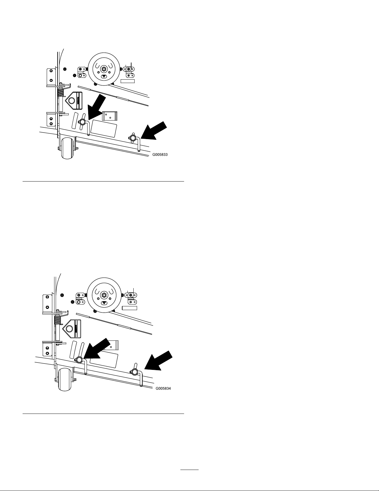
PositionB
Usethispositionwhenbagging.Alwaysalignitwith
thebloweropening.
Figure35
OperatingTips
UsingtheFastThrottleSetting
Forbestmowingandmaximumaircirculation,operate
theengineattheFASTposition.Airisrequiredto
thoroughlycutgrassclippings,sodonotsetthe
height-of-cutsolowastototallysurroundthemower
inuncutgrass.Alwaystrytohave1sideofthemower
freefromuncutgrass,whichallowsairtobedrawn
intothemower.
CuttingaLawnfortheFirstTime
Cutgrassslightlylongerthannormaltoensurethat
thecuttingheightofthemowerdoesnotscalpany
unevenground.However,thecuttingheightusedin
thepastisgenerallythebestonetouse.Whencutting
g005833
grasslongerthan15cm(6inches)tall,youmaywant
tocutthelawntwicetoensureanacceptablequality
ofcut.
CuttingaThirdoftheGrassBlade
PositionC
Thisisthefullopenposition.Thesuggestedusefor
thispositionisasfollows:
•Tall,densegrassmowingconditions
•Wetconditions
•Lowerstheengine-powerconsumption
•Allowsincreasedgroundspeedinheavyconditions
Itisbesttocutonlyaboutathirdofthegrassblade.
Cuttingmorethanthatisnotrecommendedunless
grassissparse,oritislatefallwhengrassgrows
moreslowly.
AlternatingtheMowingDirection
Alternatethemowingdirectiontokeepthegrass
standingstraight.Thisalsohelpsdisperseclippings
whichenhancesdecompositionandfertilization.
MowingatCorrectIntervals
Grassgrowsatdifferentratesatdifferenttimesof
theyear.T omaintainthesamecuttingheight,mow
moreofteninearlyspring.Asthegrassgrowthrate
slowsinmidsummer,mowlessfrequently .Ifyou
cannotmowforanextendedperiod,rstmowata
highcuttingheight,thenmowagain2dayslaterata
lowerheightsetting.
UsingaSlowerCuttingSpeed
Toimprovecutquality,useaslowergroundspeed
incertainconditions.
Figure36
g005834
AvoidingCuttingTooLow
Whenmowinguneventurf,raisethecuttingheight
toavoidscalpingtheturf.
StoppingtheMachine
Ifyoumuststoptheforwardmotionofthemachine
whilemowing,aclumpofgrassclippingsmay
28
Page 29
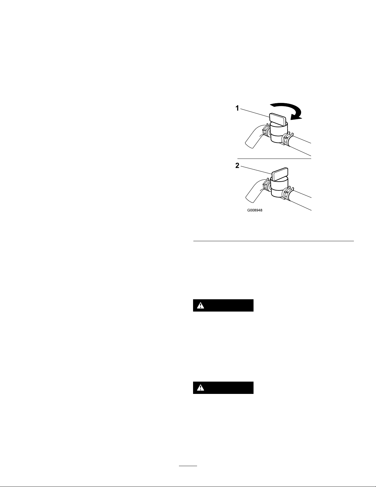
dropontoyourlawn.T oavoidthis,moveontoa
previouslycutareawiththebladesengagedoryou
candisengagethemowerdeckwhilemovingforward.
KeepingtheUndersideofthe
MowerClean
Cleanclippingsanddirtfromtheundersideofthe
moweraftereachuse.Ifgrassanddirtbuildupinside
themower,cuttingqualitywilleventuallybecome
unsatisfactory.
MaintainingtheBlade(s)
Maintainasharpbladethroughoutthecuttingseason
becauseasharpbladecutscleanlywithouttearingor
shreddingthegrassblades.T earingandshredding
turnsgrassbrownattheedges,whichslowsgrowth
andincreasesthechanceofdisease.Checkthe
mowerbladesaftereachuseforsharpness,and
foranywearordamage.Filedownanynicksand
sharpenthebladesasnecessary.Ifabladeis
damagedorworn,replaceitimmediatelywitha
genuineT ororeplacementblade.
UsingtheFuel-Shutoff Valve
Thefuel-shutoffvalveislocatedundertheseat.Move
theseatforwardtoaccessit.
Closethefuel-shutoffvalvefortransport,maintenance,
andstorage.
Ensurethatthefuel-shutoffvalveisopenwhen
startingtheengine.
AfterOperation
AfterOperationSafety
GeneralSafety
•Cleangrassanddebrisfromthecuttingunits,
mufers,andenginecompartmenttohelpprevent
res.Cleanupoilorfuelspills.
•Shutoffthefuelbeforestoringortransportingthe
machine.
•Disengagethedrivetotheattachmentwhenever
youaretransportingornotusingthemachine.
•Usefull-widthrampsforloadingthemachineinto
atrailerortruck.
•Tiethemachinedownsecurelyusingstraps,
chains,cable,orropes.Bothfrontandrearstraps
shouldbedirecteddownandoutwardfromthe
machine.
•Allowtheenginetocoolbeforestoringthemachine
inanyenclosure.
•Shutoffthefuelbeforestoringortransportingthe
machine.
•Neverstorethemachineorfuelcontainerwhere
thereisanopename,spark,orpilotlight,such
asonawaterheateroronotherappliances.
g008948
Figure37
1.On2.Off
Usingthe Drive-Wheel-Release Valves
WARNING
Handsmaybecomeentangledintherotating
drivecomponentsbelowtheenginedeck,
whichcouldresultinseriousinjury.
Shutofftheengine,removethekey,andallow
allmovingpartstostopbeforeaccessingthe
drive-wheel-releasevalves.
WARNING
Theengineandhydraulic-driveunitscan
becomeveryhot.Touchingahotengineor
hydraulic-driveunitscancausesevereburns.
Allowtheengineandhydraulic-driveunits
tocoolcompletelybeforeaccessingthe
drive-wheel-releasevalves.
29
Page 30
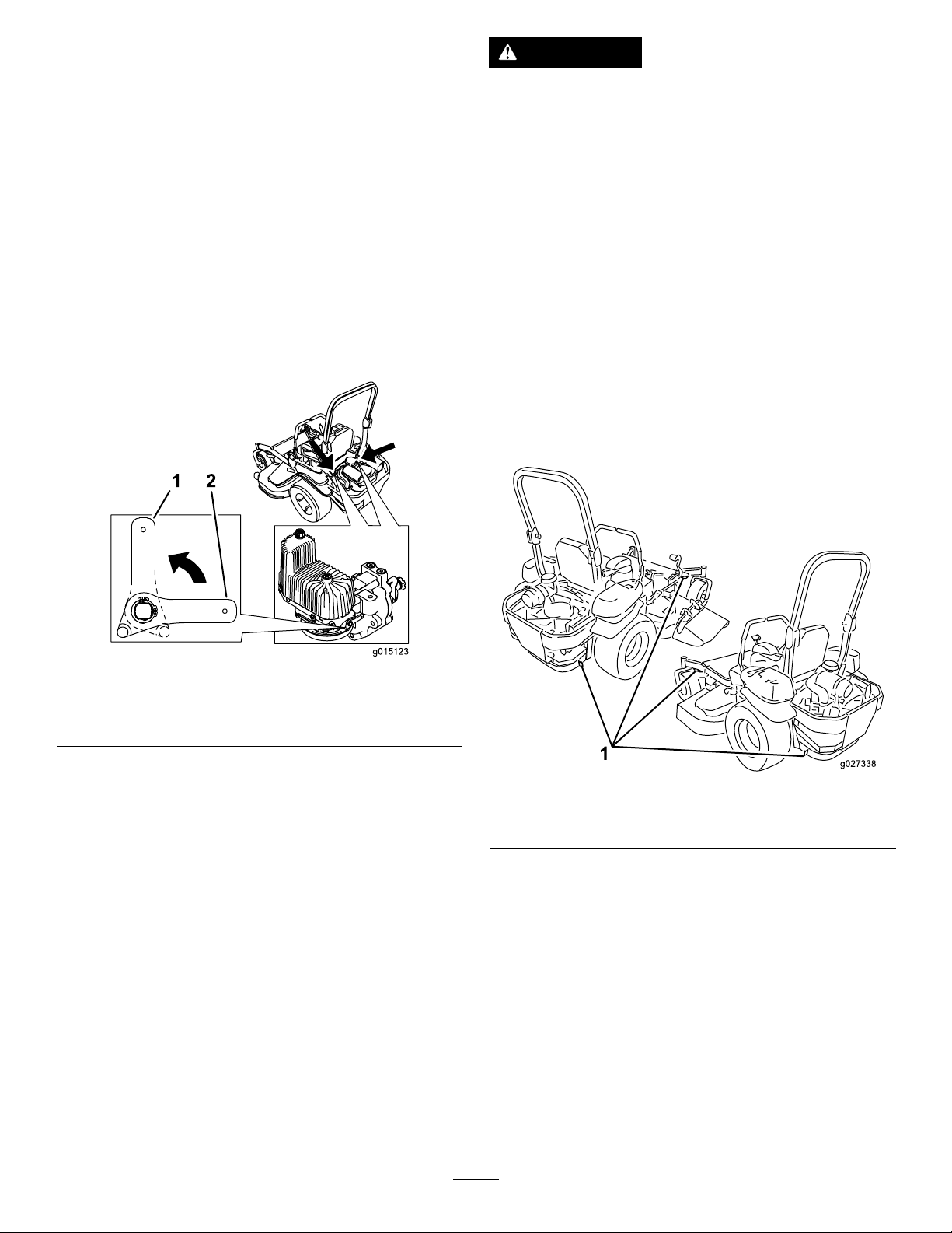
Thedrive-wheel-releasevalvesarelocatedinthe
backofeachhydraulic-driveunit,undertheseat.
Note:Makesurethatthereleasevalvesareinthe
fullyhorizontalpositionwhenoperatingthemachine
orseveredamagetothehydraulicsystemcanoccur.
1.Disengagetheblade-controlswitch(PTO),turn
theignitionkeytotheOFFposition,movethe
leverstotheNEUTRAL-LOCKposition,engagethe
parkingbrake,andremovethekey.
WARNING
Drivingonthestreetorroadwaywithout
turnsignals,lights,reectivemarkings,ora
slow-moving-vehicleemblemisdangerous
andcanleadtoaccidentscausingpersonal
injury.
Donotdrivethemachineonapublicstreet
orroadway.
2.Rotatetherelease-valveleversverticallytopush
themachine(Figure38).
Note:Thisallowshydraulicuidtobypassthe
pumpenablingthewheelstoturn.
3.Disengagetheparkingbrakebeforepushing
themachine.
Figure38
1.Ifyouareusingatrailer,connectittothetowing
vehicle,andconnectthesafetychains.
2.Ifapplicable,connectthetrailerbrakes.
3.Loadthemachineontothetrailerortruck.
4.Shutofftheengine,removethekey,engagethe
parkingbrake,andclosethefuelvalve.
5.Usethetie-downloopsonthemachineto
securelyfastenittothetrailerortruckwith
straps,chains,cable,orropes(Figure39).
g015123
1.Verticaltopushthe
machine
4.Rotatetherelease-valvelevershorizontallyto
runthemachine(Figure38).
2.Horizontaltorunthe
machine
TransportingtheMachine
Useaheavy-dutytrailerortrucktotransportthe
machine.Ensurethatthetrailerortruckhasall
thenecessarybrakes,lighting,andmarkingas
requiredbylaw.Pleasecarefullyreadallthesafety
instructions.Knowingthisinformationcouldhelpyou,
yourfamily,pets,orbystandersavoidinjury .
g027338
Figure39
1.Tractionunittie-downloops
LoadingtheMachine
Useextremecautionwhenloadingorunloading
machinesontoatraileroratruck.Useafull-width
rampthatiswiderthanthemachineforthisprocedure.
Backuptherampanddriveforwarddowntheramp
(Figure40).
30
Page 31
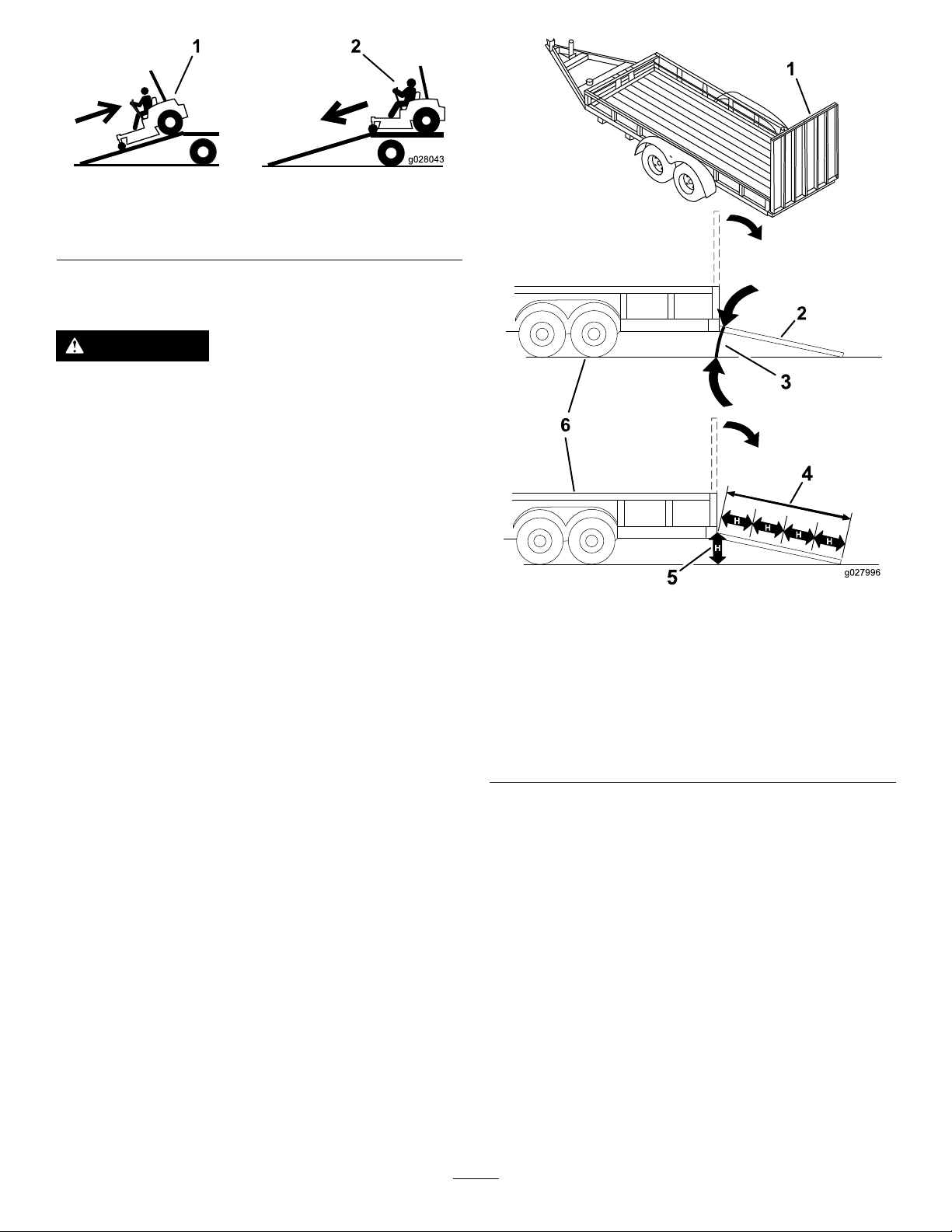
Figure40
g028043
1.Backthemachineupthe
ramp.
2.Drivethemachineforward
downtheramp.
Important:Donotusenarrowindividualramps
foreachsideofthemachine.
WARNING
Loadingamachineontoatrailerortruck
increasesthepossibilityoftip-overandcould
causeseriousinjuryordeath(Figure41).
•Useextremecautionwhenoperatinga
machineonaramp.
•Useonlyafull-widthramp;donotuse
individualrampsforeachsideofthe
machine.
•Donotexceeda15-degreeanglebetween
therampandthegroundorbetweenthe
rampandthetrailerortruck.
•Ensurethatthelengthoframpisatleast
4timesaslongastheheightofthetrailer
ortruckbedtotheground.Thisensures
thattherampangledoesnotexceed15
degreesonatground.
•Backuprampsanddriveforwarddown
ramps.
1.Full-widthrampinstowed
position
2.Sideviewoffull-width
rampinloadingposition
3.Notgreaterthan
15degrees
g027996
Figure41
4.Rampisatleast4times
aslongastheheightof
thetrailerortruckbedto
theground
5.H=heightofthetraileror
truckbedtotheground
6.Trailer
•Avoidsuddenaccelerationordeceleration
whiledrivingthemachineonarampas
thiscouldcausealossofcontrolora
tip-oversituation.
31
Page 32

Maintenance
RecommendedMaintenanceSchedule(s)
MaintenanceService
Interval
Aftertherst8hours
Aftertherst100hours
Aftertherst250hours
Beforeeachuseordaily
Every50hours
Every100hours
MaintenanceProcedure
•Changetheengineoil.
•Checkthewheellugnuttorque.
•Checkthewheel-hubslotted-nuttorque.
•Checktheparkingbrakeadjustment.
•Changethehydraulicltersandhydraulicuidwhenusinganytypeofuid.
•Checkthesafetysystem.
•Checktheengine-oillevel.
•Checktheseatbelt.
•Checktherolloverprotectionsystem(ROPS)knobs.
•Cleantheenginescreenandtheoilcooler.
•Checkandcleanthehydraulic-unitshrouds.
•Inspecttheblades.
•Cleanthemowerdeck.
•Checkthesparkarrester(ifequipped).
•Checkthetirepressure.
•Inspectthebelts.
•Checkthehydraulic-uidlevel.
•Lubricatethemower-deck-liftpivots.
•Changetheengineoil(moreoftenindirtyordustyconditions).
•Checkandgapthesparkplugs.
•Checkandcleanengine-coolingnsandshrouds.
Every200hours
Every250hours
Every500hours
Monthly
Yearly
Yearlyorbeforestorage
•Changetheengine-oillter.
•Replacetheprimaryairlter.
•Checkthesecondaryairlter.
•ChangethehydraulicltersandhydraulicuidwhenusingMobil®1uid(more
oftenindirtyordustyconditions).
•Replacethesecondaryairlter.
•Replacethefuellter(moreoftenindirtyordustyconditions).
•Checkthewheellugnuttorque.
•Checkthewheel-hubslotted-nuttorque.
•Adjustthecaster-pivotbearing.
•Checktheparkingbrakeadjustment.
•ChangethehydraulicltersandhydraulicuidwhenusingToro®HYPR-OIL™500
hydraulicuid(moreoftenindirtyordustyconditions).
•Checkthebatterycharge.
•Greasethepump-belt-idlerarm.
•Greasethefrontcasterpivots(moreoftenindirtyordustyconditions).
•Repackthefrontcaster-wheelbearings(moreoftenindirtyordustyconditions).
•Lubricatethecaster-wheelhubs.
•Paintchippedsurfaces.
•Checkallmaintenanceprocedureslistedabovebeforestorage.
Important:Refertoyourengineoperator'smanualforadditionalmaintenanceprocedures.
32
Page 33

CAUTION
Ifyouleavethekeyintheignitionswitch,someonecouldaccidentlystarttheengineand
seriouslyinjureyouorotherbystanders.
Removethekeyfromtheignitionbeforeyouperformanymaintenance.
Pre-Maintenance
Procedures
MaintenanceandStorage
•Beforerepairingthemachinedothefollowing:
–Disengagethedrives.
–Engagetheparkingbrake.
–Shutofftheengineandremovethekey.
–Disconnectthespark-plugwire.
•Parkthemachineonalevelsurface.
•Cleangrassanddebrisfromthecuttingunit,
drives,mufers,andenginetohelppreventres.
•Cleanupoilorfuelspills.
•Lettheenginecoolbeforestoringthemachine.
•Donotstorethemachineorfuelnearamesor
drainthefuelindoors.
•Donotallowuntrainedpersonneltoservicethe
machine.
•Usejackstandstosupportthemachineand/or
componentswhenrequired.
•Carefullyreleasepressurefromcomponentswith
storedenergy.
•Disconnectthebatteryorremovethespark-plug
wirebeforemakinganyrepairs.Disconnectthe
negativeterminalrstandthepositiveterminal
last.Connectthepositiveterminalrstand
negativelast.
•Usecarewhencheckingtheblades.Wrapthe
blade(s)orwearthicklypaddedgloves,anduse
cautionwhenservicingthem.Onlyreplaceblades;
donotstraightenorweldthem.
•Keepyourhandsandfeetawayfrommoving
parts.Ifpossible,donotmakeadjustmentswith
theenginerunning.
•Keepallpartsingoodworkingcondition
andallhardwaretightened,especiallythe
blade-attachmentbolts.Replaceallwornor
damageddecals.
•Neverinterferewiththeintendedfunctionofa
safetydeviceorreducetheprotectionprovided
byasafetydevice.Checktheirproperoperation
regularly.
•Toensureoptimumperformanceandcontinued
safetycerticationofthemachine,useonly
genuineT ororeplacementpartsandaccessories.
Replacementpartsandaccessoriesmadeby
othermanufacturerscouldbedangerous,and
suchusecouldvoidtheproductwarranty.
•Checktheparkingbrakeoperationfrequently.
Adjustandserviceasrequired.
33
Page 34
Lubrication
GreasingtheMower
Greasemorefrequentlywhenoperatingconditions
areextremelydustyorsandy.
GreaseType:No.2general-purposelithium-based
ormolybdenum-basedgrease
1.Disengagetheblade-controlswitch(PTO),move
themotion-controlleverstotheNEUTRAL-LOCK
position,andengagetheparkingbrake.
2.Shutofftheengine,removethekey ,andwait
forallmovingpartstostopbeforeleavingthe
operatingposition.
3.Cleanthegreasettingswitharag.
Note:Makesurethatyouscrapeanypaintoff
thefrontofthetting(s).
4.Connectagreaseguntothetting.
5.Pumpgreaseintothettingsuntilgreasebegins
tooozeoutofthebearings.
6.Wipeupanyexcessgrease.
AddingLightOilorSpray
ServiceInterval:Yearly—Greasethepump-belt-idler
arm.
Yearly—Greasethefrontcasterpivots(more
oftenindirtyordustyconditions).
Yearly—Repackthefrontcaster-wheelbearings
(moreoftenindirtyordustyconditions).
1.Disengagetheblade-controlswitch(PTO),move
themotion-controlleverstotheNEUTRAL-LOCK
position,andengagetheparkingbrake.
2.Shutofftheengine,removethekey ,andwait
forallmovingpartstostopbeforeleavingthe
operatingposition.
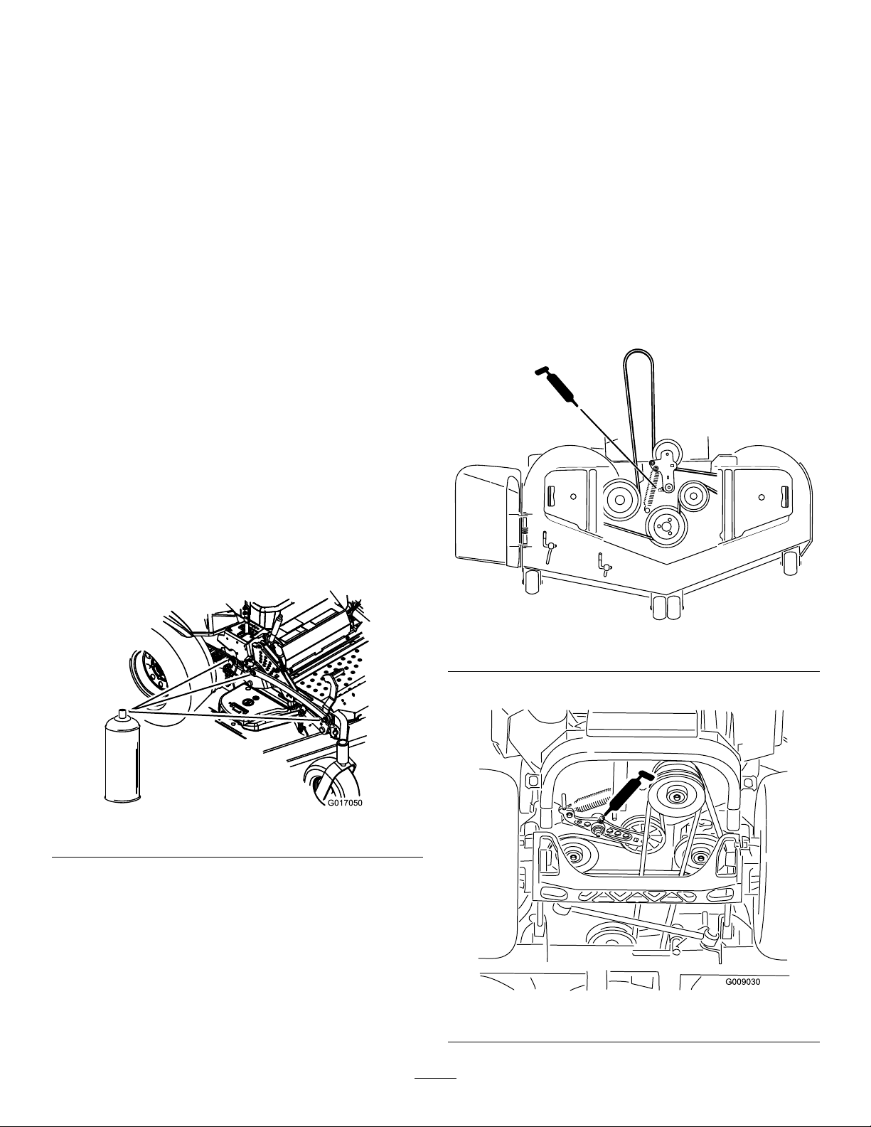
3.Greasethemowerdeckidler-pulleypivotuntil
greasecomesoutthebottom(Figure43).
Lubrication
ServiceInterval:Every100hours
Lubricatethedeck-liftpivots.
g185957
Figure43
4.Greasethedrive-belt-idlerarm(Figure44).
g017050
Figure42
g009030
Figure44
34
Page 35
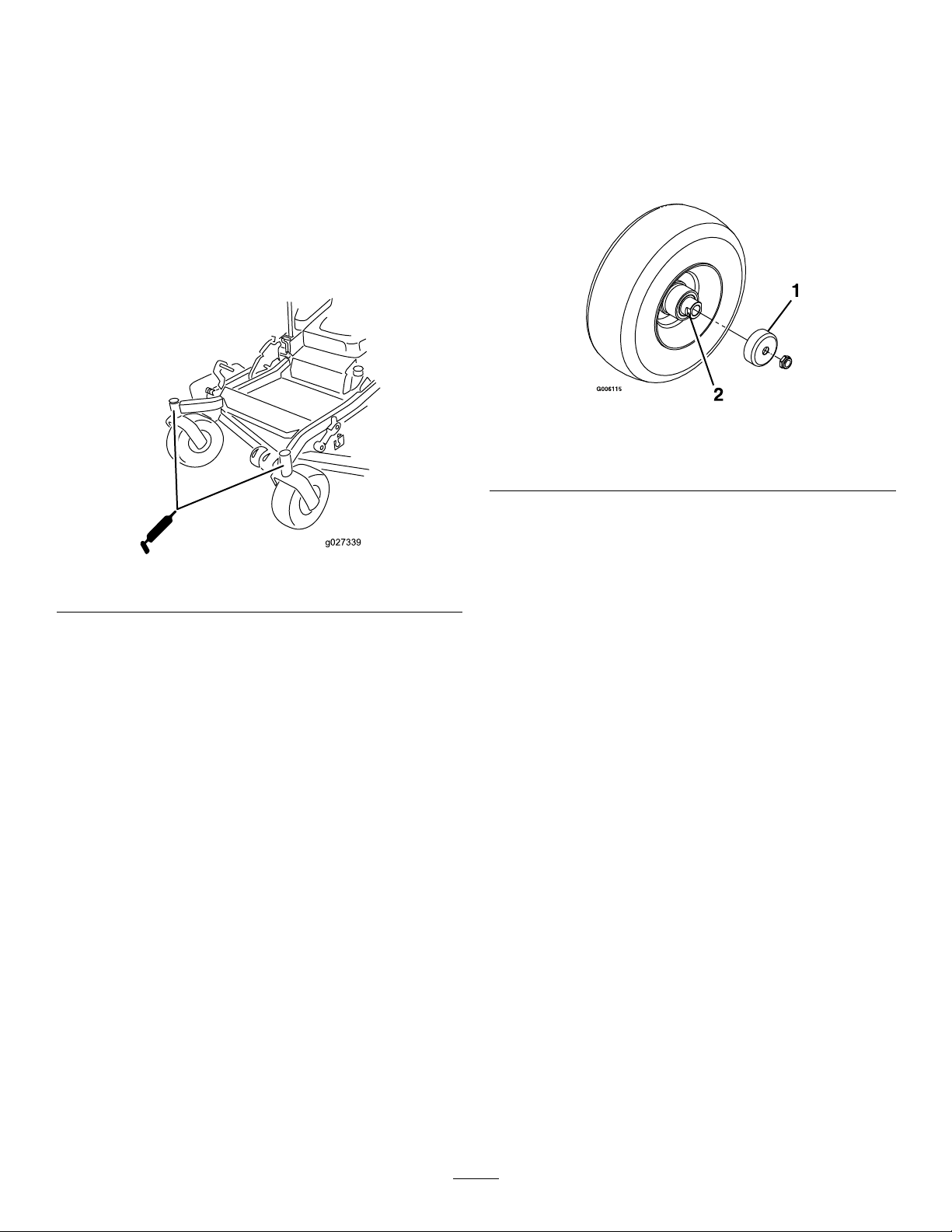
5.Removethedustcapandadjustthecaster
pivots.
Note:Keepthedustcapoffuntilgreasingis
done.
6.Removethehexplug.
7.Threadagreasettingintothehole.
8.Pumpgreaseintothettinguntilitoozesout
aroundthetopbearing.
9.Removethegreasettinginthehole.
10.Installthehexpluganddustcap(Figure45).
Lubricatingthe Caster-WheelHubs
ServiceInterval:Yearly
1.Shutofftheengine,waitforallmovingpartsto
stop,removethekey ,andengagetheparking
brake.
g006115
Figure46
Figure45
11.Greasethecaster-wheelbearings(Figure45).
1.Sealguard2.Spacernutwithwrench
2.Raisethemowerforaccess.
3.Removethecasterwheelfromthecasterforks.
g027339
4.Removethesealguardsfromthewheelhub.
5.Removeaspacernutfromtheaxleassemblyin
thecasterwheel.
ats
Note:Thread-lockingadhesivehasbeen
appliedtolockthespacernutstotheaxle.
6.Removetheaxle(withtheotherspacernutstill
assembledtoit)fromthewheelassembly.
7.Pryoutsealsandinspectbearingsforwearor
damageandreplaceifnecessary.
8.Packthebearingswithageneral-purpose
grease.
9.Insert1bearingand1newsealintothewheel.
Note:Replacetheseals.
10.Iftheaxleassemblyismissingbothspacernuts,
applyathread-lockingadhesiveto1spacernut
andthreaditontotheaxlewiththewrenchats
facingoutward.
Note:Donotthreadthespacernutallof
thewayontotheendoftheaxle.Leave
approximately3mm(1/8inch)fromtheouter
surfaceofthespacernuttotheendoftheaxle
insidethenut.
11.Inserttheassemblednutandaxleintothewheel
onthesideofthewheelwiththenewsealand
bearing.
35
Page 36

12.Withtheopenendofthewheelfacingup,ll
theareainsidethewheelaroundtheaxlefullof
general-purposegrease.
13.Insertthesecondbearingandnewsealintothe
wheel.
14.Applyathread-lockingadhesivetothesecond
spacernut,andthreaditontotheaxlewiththe
wrenchatsfacingoutward.
15.T orquethenutto8to9N∙m(75to80in-lb),
loosen,thentorqueto2to3N∙m(20to25in-lb).
Note:Makesurethattheaxledoesnotextend
beyondeithernut.
16.Installthesealguardsoverthewheelhub,and
insertthewheelintothecasterfork.
EngineMaintenance
WARNING
Contactwithhotsurfacesmaycausepersonal
injury.
Keepyourhands,feet,face,clothing,and
otherbodypartsawaythemuferandother
hotsurfaces.
EngineSafety
Shutofftheenginebeforecheckingtheoiloradding
oiltothecrankcase.
17.Installthecasterboltandtightenthenutfully.
Important:Topreventsealandbearingdamage,
checkthebearingadjustmentoften.Spinthe
castertire.Thetireshouldnotspinfreely(more
than1or2revolutions)orhaveanysideplay.If
thewheelspinsfreely,adjustthetorqueonthe
spacernutuntilthereisaslightamountofdrag.
Applyanotherlayerofthread-lockingadhesive.
ServicingtheAirCleaner
ServiceInterval:Every250hours—Replacethe
primaryairlter.
Every250hours—Checkthesecondaryair
lter.
Every500hours—Replacethesecondaryair
lter.
Note:Servicetheaircleanermorefrequentlyif
operatingconditionsareextremelydustyorsandy .
RemovingtheFilters
1.Disengagetheblade-controlswitch(PTO),move
themotion-controlleverstotheNEUTRAL-LOCK
position,andengagetheparkingbrake.
2.Shutofftheengine,removethekey ,andwait
forallmovingpartstostopbeforeleavingthe
operatingposition.
3.Pushdowntoreleasetheretainingclampson
theaircleaner,andpulltheair-cleanercoveroff
theair-cleanerbody(Figure47).
4.Cleantheinsideoftheair-cleanercoverwith
compressedair.
5.Gentlyslidetheprimarylteroutofthe
air-cleanerbody(Figure47).Avoidknockingthe
lterintothesideofthebody.
6.Removethesecondarylteronlyifyouintend
toreplaceit.
Important:Neverattempttocleanthe
secondarylter.Ifthesecondarylteris
dirty,thentheprimarylterisdamagedand
youshouldreplacebothlters.
7.Inspecttheprimarylterfordamagebylooking
intothelterwhileshiningabrightlightonthe
outsideofthelter.
Note:Holesinthelterappearasbrightspots.
Note:Ifthelterisdamageddiscardit.
36
Page 37
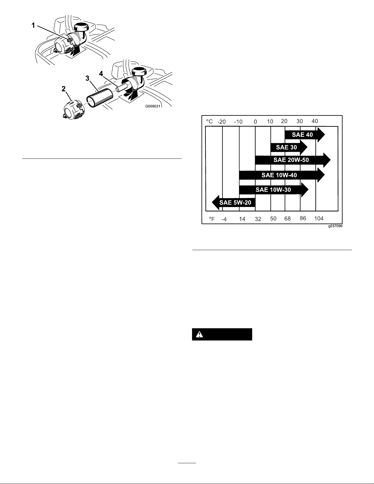
Figure47
5.Installtheair-cleanercoverwiththebreathercap
down,androtatesothattheretainingclamps
lockthecoverinplace(Figure47).
ServicingtheEngineOil
OilType:Detergentoil(APIserviceSG,SH,SJ,or
higher)
CrankcaseCapacity:withalterchange,2.3L(2.4
USqt);withoutalterchange,2.1L(2.2USqt)
Viscosity:Seethetablebelow.
g009031
1.Air-cleanerclamps
2.Air-cleanercover
3.Primaryairlter
4.Secondaryairlter
ServicingthePrimaryFilter
1.Donotcleanthepaperlter,replaceit(Figure
47).
2.Inspecttheelementfortears,anoilylm,or
damagetotherubberseal.
3.Replacethepaperelementifitisdamaged.
ServicingtheSecondaryFilter
Donotcleanthesecondarylter,replaceit.
Important:Donotattempttocleanthesecondary
lter.Ifthesecondarylterisdirty ,thenthe
primarylterisdamagedandyoushouldreplace
bothlters.
InstallingtheFilters
Important:Topreventenginedamage,always
operatetheenginewithbothairltersandthe
coverinstalled.
1.Ifinstallingnewlters,checkeachlterfor
shippingdamage.
Note:Donotuseadamagedlter.
2.Ifthesecondarylterisbeingreplaced,carefully
slideitintothelterbody(Figure47).
3.Carefullyslidetheprimarylteroverthe
secondarylter(Figure47).
4.Ensurethatitisfullyseatedbypushingonthe
outerrimofthelterwhileinstallingit.
Important:Donotpressonthesoftinside
areaofthelter.
g037096
Figure48
Note:Useofmulti-gradeoils(5W-20,10W-30,or
10W-40)willincreaseoilconsumption.Checktheoil
levelmorefrequentlywhenusingthem.
CheckingtheEngine-OilLevel
ServiceInterval:Beforeeachuseordaily
Note:Checktheoilwhentheengineiscold.
WARNING
Contactwithhotsurfacesmaycausepersonal
injury.
Keepyourhands,feet,face,clothing,and
otherbodypartsawayfromthemuferand
otherhotsurfaces.
Important:Donotoverllthecrankcasewithoil
becausedamagetotheenginemayresult.Donot
runenginewithoilbelowtheLowmarkbecause
theenginemaybedamaged.
1.Disengagetheblade-controlswitch(PTO),move
themotion-controlleverstotheNEUTRAL-LOCK
position,andengagetheparkingbrake.
37
Page 38
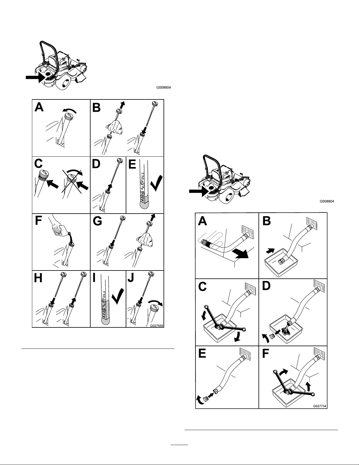
2.Shutofftheengine,removethekey ,andwait
forallmovingpartstostopbeforeleavingthe
operatingposition(Figure49).
ChangingtheEngineOil
ServiceInterval:Aftertherst8hours
Every100hours(moreoftenindirtyordusty
conditions).
Note:Disposeoftheusedoilatarecyclingcenter.
1.Starttheengineandletitrunfor5minutes.
Note:Thiswarmstheoilsoitdrainsbetter.
2.Parkthemachinesothattherearisslightly
g008804
lowerthanthefronttoensurethattheoildrains
completely.
3.Disengagetheblade-controlswitch(PTO),move
themotion-controlleverstotheNEUTRAL-LOCK
position,andengagetheparkingbrake.
4.Shutofftheengine,removethekey ,andwait
forallmovingpartstostopbeforeleavingthe
operatingposition(Figure50).
Figure49
g008804
g027659
g027734
Figure50
38
Page 39
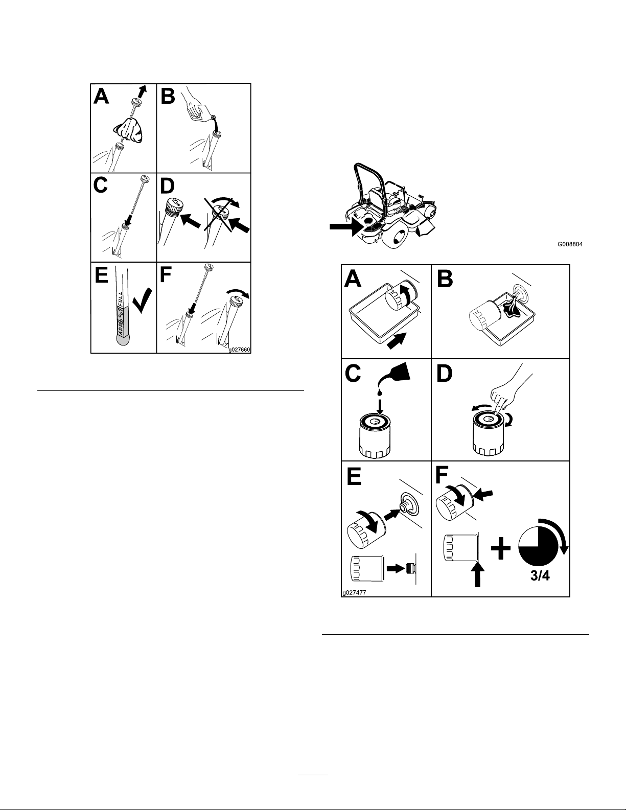
5.Slowlypourapproximately80%ofthespecied
oilintothellertubeandslowlyaddthe
additionaloiltobringittotheFullmark(Figure
51).
ChangingtheEngine-OilFilter
ServiceInterval:Every200hours
Note:Changetheengine-oilltermorefrequently
whenoperatingconditionsareextremelydustyor
sandy.
1.Draintheoilfromtheengine;refertoChanging
theEngineOil(page38).
2.Changetheengine-oillter(Figure52).
g008804
Figure51
6.Starttheengineanddrivetoaatarea.
7.Checktheoillevelagain.
g027660
g027477
Figure52
Note:Ensurethattheoil-ltergaskettouches
theengine,andthenanextra3/4turnis
completed.
3.Fillthecrankcasewiththepropertypeofnew
oil;refertoChangingtheEngineOil(page38).
39
Page 40
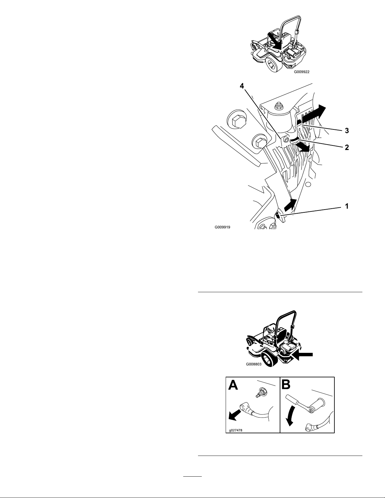
ServicingtheSparkPlugs
ServiceInterval:Every100hours—Checkandgap
thesparkplugs.
Makesurethattheairgapbetweenthecenterand
sideelectrodesiscorrectbeforeinstallingthespark
plug.Useasparkplugwrenchforremovingand
installingthesparkplug(s)andagappingtool/feeler
gaugetocheckandadjusttheairgap.Installanew
sparkplug(s)ifnecessary.
Type:NGKBPR4ESorequivalent
AirGap:0.76mm(0.030inch)
RemovingtheSparkPlug
1.Shutofftheengine,removethekey ,andwait
forallmovingpartstostopbeforeleavingthe
operatingposition.
2.Disengagetheblade-controlswitch(PTO),move
themotion-controlleverstotheNEUTRAL-LOCK
position,andengagetheparkingbrake.
3.Removethelefthydraulic-unitshroudinthe
orderlistedinFigure53.
g009922
Note:Thisgivesyouaccesstothefrontspark
plug.
1.Pullthistabouttothe
sideinthedirectionofthe
arrow
2.Pulltheshroudoffthis
frametabinthedirection
ofthearrow
4.Removethesparkplug.
g009919
Figure53
3.Pulltheshroudoffthis
frametabinthedirection
ofthearrow
4.Shroud
g008803
g027478
Figure54
40
Page 41
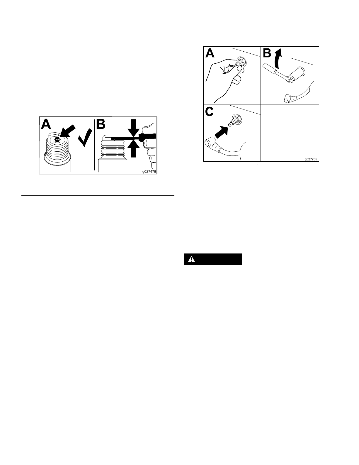
5.Installthelefthydraulic-unitshroud(Figure53).
CheckingtheSparkPlug
Important:Donotcleanthesparkplug(s).
Alwaysreplacethesparkplug(s)whenithas:a
blackcoating,wornelectrodes,anoilylm,or
cracks.
Ifyouseelightbrownorgrayontheinsulator,the
engineisoperatingproperly.Ablackcoatingonthe
insulatorusuallymeanstheaircleanerisdirty .
Setthegapto0.76mm(0.03inch).
Figure55
InstallingtheSparkPlug
Tightenthesparkplug(s)to24.4to29.8N∙m(18to
22ft-lb).
g027735
g027479
Figure56
CheckingtheSpark Arrester
ForModelswithaSparkArrester
ServiceInterval:Every50hours
WARNING
Hotexhaustsystemcomponentsmayignite
fuelvaporsevenafteryoushutofftheengine.
Hotparticlesexhaustedduringengine
operationmayigniteammablematerials.
Firemayresultinpersonalinjuryorproperty
damage.
Donotfuelorruntheengineunlessaspark
arresterisinstalled.
1.Shutofftheengine,waitforallmovingpartsto
stop,removethekey ,andengagetheparking
brake.
2.Waitforthemufertocool.
3.Ifthereareanybreaksinthescreenorwelds
areobserved,replacethearrester.
4.Ifthescreenisplugged,removethearrester
andshakelooseparticlesoutofthearrester,
andcleanthescreenwithawirebrush(soakin
solventifnecessary).
5.Installthearresterontheexhaustoutlet.
41
Page 42
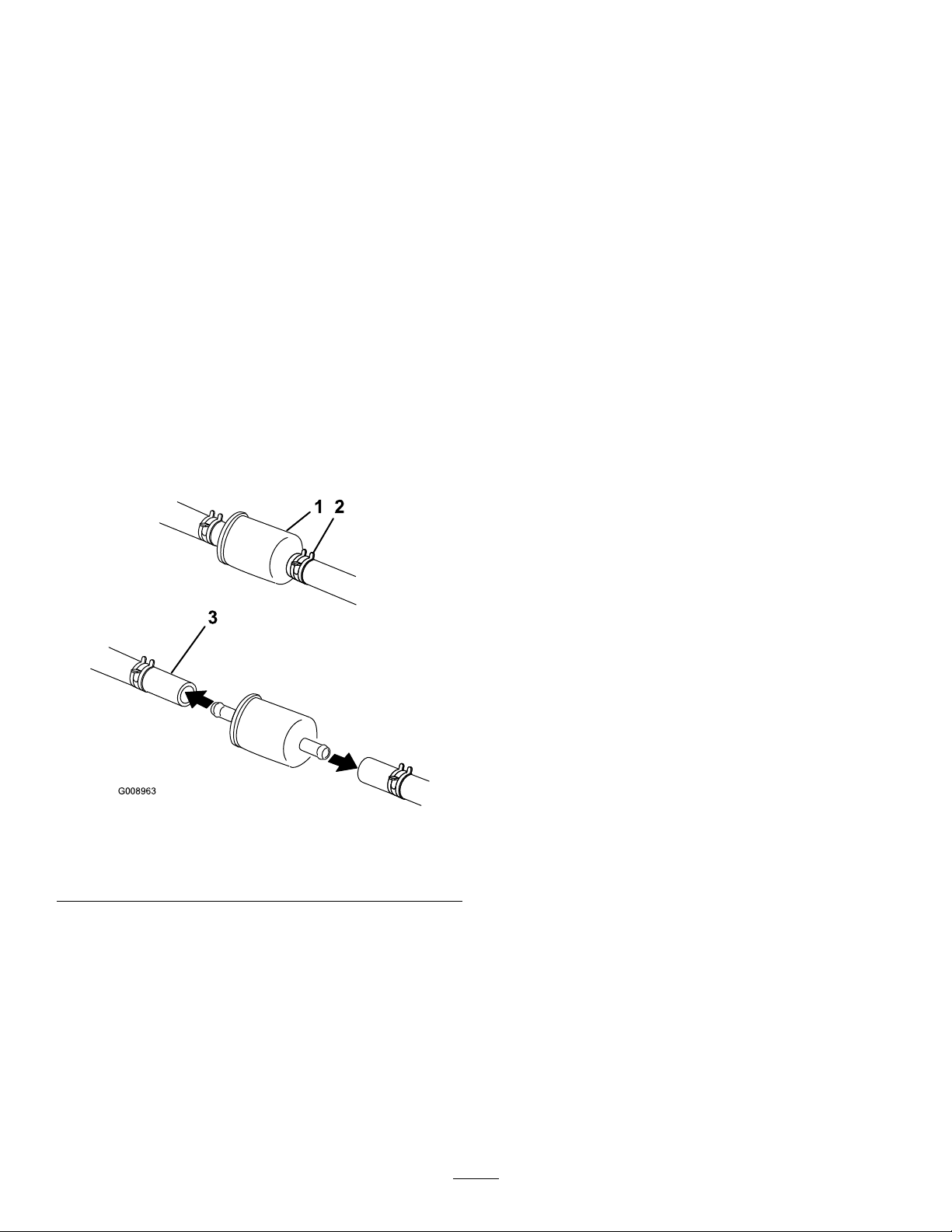
FuelSystem
ServicingtheFuelTank
Maintenance
ReplacingtheFuelFilter
ServiceInterval:Every500hours/Y early(whichever
comesrst)(moreoftenindirtyor
dustyconditions).
Thefuellterislocatedneartheengineonthefront
orrearsideoftheengine.
1.Disengagetheblade-controlswitch(PTO),move
themotion-controlleverstotheNEUTRAL-LOCK
position,andengagetheparkingbrake.
2.Shutofftheengine,removethekey ,andwait
forallmovingpartstostopbeforeleavingthe
operatingposition.
3.Allowthemachinetocooldown.
4.Closethefuel-shutoffvalveundertheseat
(Figure57).
Donotattempttodrainthefueltank.Ensurethatan
AuthorizedServiceDealerdrainsthefueltankand
servicesanycomponentsofthefuelsystem.
Figure57
1.Fuellter3.Fuel-shutoffvalve
2.Hoseclamp
5.Squeezetheendsofthehoseclampstogether
andslidethemawayfromthelter(Figure57).
6.Removethelterfromthefuellines.
7.Installanewlterandmovethehoseclamps
closetothelter(Figure57).
8.Openthefuel-shutoffvalve.
Important:Installthefuellinehosesandsecure
withplastictiesthesameastheywereoriginally
installedatthefactorytokeepthefuellineaway
fromcomponentsthatcancausefuellinedamage.
g008963
42
Page 43
ElectricalSystem
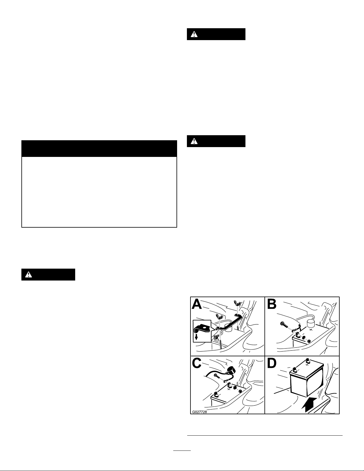
RemovingtheBattery
Maintenance
ElectricalSystemSafety
•Disconnectthebatterybeforerepairingthe
machine.Disconnectthenegativeterminalrst
andthepositivelast.Connectthepositiveterminal
rstandthenegativelast.
•Chargethebatteryinanopen,well-ventilated
area,awayfromsparksandames.Unplugthe
chargerbeforeconnectingordisconnectingthe
battery.Wearprotectiveclothinganduseinsulated
tools.
WARNING
CALIFORNIA
Proposition65Warning
Batteryposts,terminals,andrelated
accessoriescontainleadandlead
compounds,chemicalsknownto
theStateofCaliforniatocause
cancerandreproductiveharm.Wash
handsafterhandling.
WARNING
Batteryterminalsormetaltoolscouldshort
againstmetalmachinecomponentscausing
sparks.Sparkscancausethebatterygasses
toexplode,resultinginpersonalinjury.
•Whenremovingorinstallingthebattery,
donotallowthebatteryterminalstotouch
anymetalpartsofthemachine.
•Donotallowmetaltoolstoshortbetween
thebatteryterminalsandmetalpartsofthe
machine.
WARNING
Incorrectbatterycableroutingcoulddamage
themachineandcablescausingsparks.
Sparkscancausethebatterygassesto
explode,resultinginpersonalinjury.
•Alwaysdisconnectthenegative(black)
batterycablebeforedisconnectingthe
positive(red)cable.
•Alwaysconnectthepositive(red)battery
cablebeforeconnectingthenegative
(black)cable.
ServicingtheBattery
ServiceInterval:Monthly
DANGER
Batteryelectrolytecontainssulfuricacid
whichisadeadlypoisonandcausessevere
burns.
Donotdrinkelectrolyteandavoidcontact
withskin,eyes,orclothing.Wearsafety
glassestoshieldyoureyesandrubbergloves
toprotectyourhands.
1.Disengagetheblade-controlswitch(PTO),move
themotion-controlleverstotheNEUTRAL-LOCK
position,andengagetheparkingbrake.
2.Shutofftheengine,removethekey ,andwait
forallmovingpartstostopbeforeleavingthe
operatingposition.
3.RemovethebatteryasshowninFigure58.
g027728
Figure58
43
Page 44
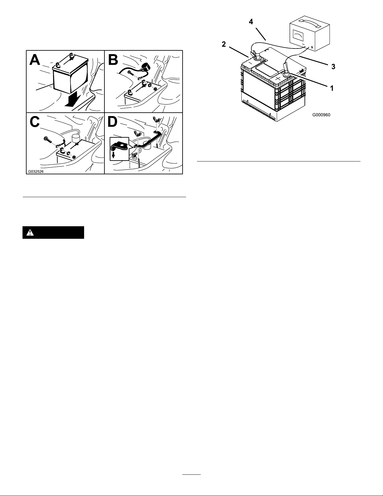
InstallingtheBattery
Note:Positionthebatteryinthetraywiththeterminal
postsoppositefromthehydraulictank(Figure58).
g000960
Figure60
Figure59
ChargingtheBattery
WARNING
Chargingthebatteryproducesgassesthat
canexplode.
Neversmokenearthebatteryandkeepsparks
andamesawayfrombattery.
Important:Alwayskeepthebatteryfullycharged
(1.265specicgravity).Thisisespecially
importanttopreventbatterydamagewhenthe
temperatureisbelow0°C(32°F).
1.Positivebatterypost
2.Negativebatterypost
g032526
3.Red(+)chargerlead
4.Black(-)chargerlead
1.Chargebatteryfor10to15minutesat25to30
Aor30minutesat10A.
2.Whenthebatteryisfullycharged,unplug
thechargerfromtheelectricaloutlet,then
disconnectthechargerleadsfromthebattery
posts(Figure60).
3.Installthebatteryinthemachineandconnect
thebatterycables;refertoInstallingtheBattery
(page44).
Note:Donotrunthemachinewiththebattery
disconnected,electricaldamagemayoccur.
44
Page 45
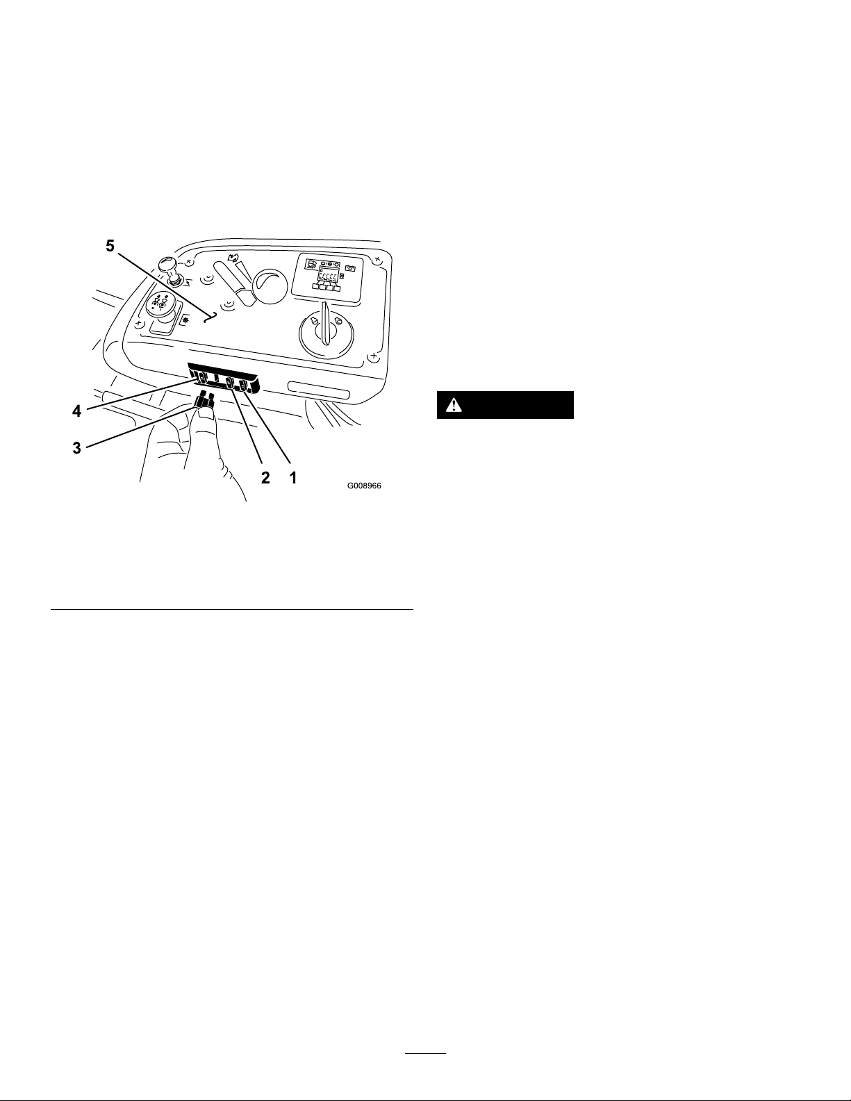
ServicingtheFuses
DriveSystem
Theelectricalsystemisprotectedbyfuses.Itrequires
nomaintenance,however,ifafuseblowscheckthe
component/circuitforamalfunctionorshort.
1.Thefusesarelocatedontheconsoletotheright
oftheseat(Figure61).
2.T oreplacethefuses,pulloutonthefuseto
removeit.
3.Installanewfuse(Figure61).
Maintenance
CheckingtheSeatBelt
ServiceInterval:Beforeeachuseordaily
Inspecttheseatbeltforwear,cuts,andproper
operationoftheretractorandbuckle.Replacethe
seatbeltifitisdamaged.
CheckingtheRollover ProtectionSystem(ROPS) Knobs
ServiceInterval:Beforeeachuseordaily
WARNING
Toavoidinjuryordeathfromrollover:keep
therollbarinthefullyraisedlockedposition
andusetheseatbelt.
Figure61
1.Optionalaccessory(15A)4.Main(25A)
2.Charge(25A)
3.PTO(10A)
5.Console
g008966
Ensurethattheseatissecuredtothe
machine.
Checkthatboththemountinghardwareandtheknobs
areingoodworkingcondition.Makesurethatthe
knobsarefullyengagedwiththeROPSintheraised
position.Theupperhoopoftherollbarmayneed
tobepushedforwardorpulledrearwardtogetboth
knobsfullyengaged.
45
Page 46
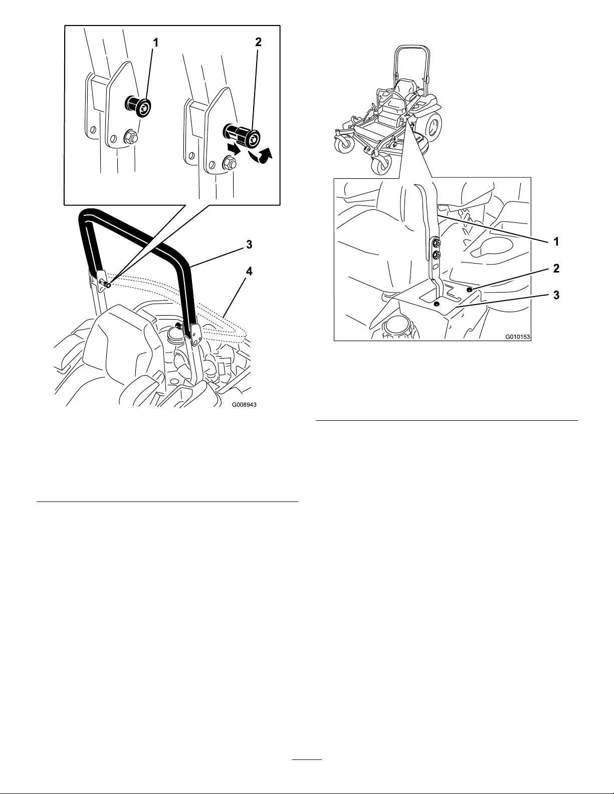
8.Tightenthestopplate(Figure63).
Figure62
1.ROPSknob(locked
position)
2.PulltheROPSknobout
androtateit90°tochange
therollbarposition.
3.Rollbarintheupright
position
4.Rollbarinthefolded
position
AdjustingtheTracking
1.Disengagetheblade-controlswitch(PTO).
2.Drivetoanopenatarea,movethe
motion-controlleverstotheNEUTRAL-LOCK
position.
3.Movethethrottlemidwaybetweenfastandslow.
4.Movebothmotion-controlleversalltheway
forwarduntiltheybothhitthestopsintheT-slot.
5.Checkwhichwaythemachinetracks.
6.Ifittrackstotheright,loosentheboltsandadjust
theleftstopplatebackwardontheleftT-slot
untilthemachinetracksstraight(Figure63).
7.Ifittrackstotheleft,loosentheboltsandadjust
therightstopplatebackwardontherightT-slot
untilthemachinetracksstraight(Figure63).
g010153
Figure63
Leftcontrollevershown
1.Controllever3.Stopplate
g008943
2.Bolt
CheckingtheTirePressure
ServiceInterval:Every50hours/Monthly(whichever
comesrst)
Maintaintheairpressureinthereartiresat90kPa
(13psi).Uneventirepressurecancauseunevencut.
Checkthetireswhentheyarecold,togetthemost
accuratepressurereading.
Note:Thefronttiresaresemi-pneumatictiresanddo
notrequireairpressuremaintenance.
46
Page 47
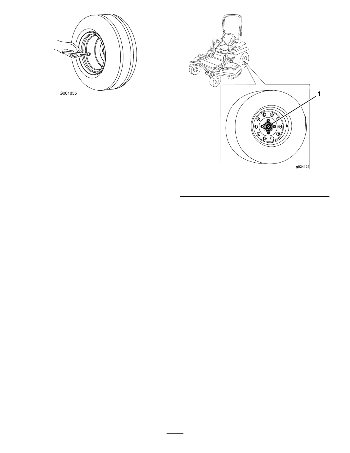
Figure64
CheckingtheWheelLug Nuts
Checkandtorquethewheellugnutsto122to129
N∙m(90to95ft-lb).
g001055
g024121
Figure65
CheckingtheWheel-Hub SlottedNut
ServiceInterval:Aftertherst100hours
Every500hours
Checkandensurethatthetorqueoftheslottednutis
286to352N∙m(211to260ft-lb).
Note:Donotuseanti-seizecompoundonthewheel
hub.
1.Slottednut
AdjustingtheCaster-Pivot Bearing
ServiceInterval:Every500hours/Y early(whichever
comesrst)
1.Disengagetheblade-controlswitch(PTO),move
themotion-controlleverstotheNEUTRAL-LOCK
position,andengagetheparkingbrake.
2.Shutofftheengine,removethekey ,andwait
forallmovingpartstostopbeforeleavingthe
operatingposition.
3.Removethedustcapfromcasterandtighten
thelocknut(Figure66).
4.Tightenthelocknutuntilthespringwashersare
at,andthenbackoffa1/4turntoproperlyset
thepreloadonthebearings(Figure66).
Important:Makesurethatthespring
washersareinstalledcorrectlyasshownin
Figure66.
5.Installthedustcap(Figure66).
47
Page 48
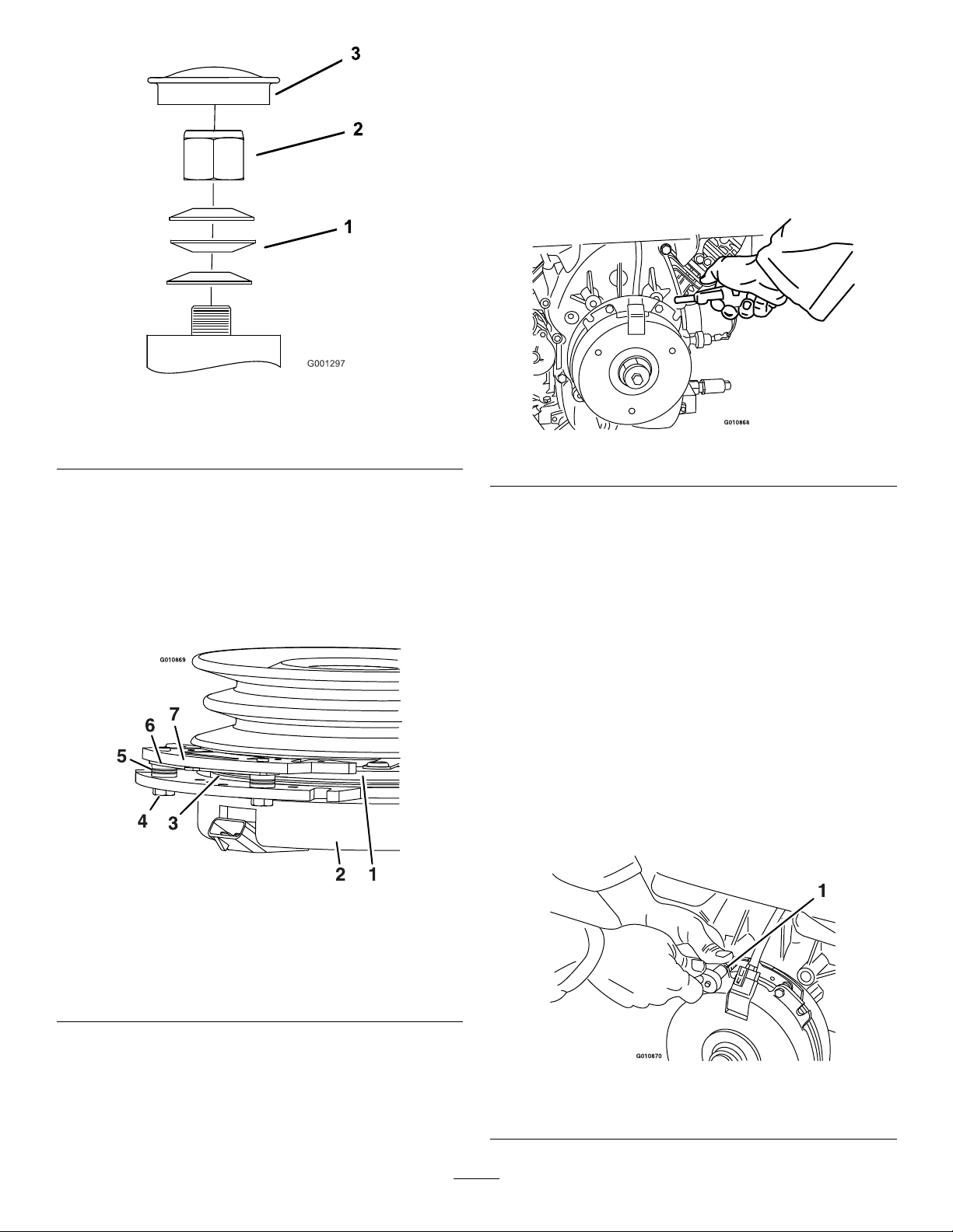
Figure66
RemovingtheClutchShim
1.Shutofftheengine,waitforallmovingpartsto
stop,removethekey ,engagetheparkingbrake,
andallowthemachinetocoolcompletelybefore
startingtheseinstructions.
2.Usinganaircompressor,blowoutanydebris
fromunderthebrakepoleandaroundthebrake
spacers(Figure68).
g001297
1.Springwashers
2.Locknut
3.Dustcap
UsingtheClutchShim
Somelatermodelyearunitshavebeenbuiltwith
clutchesthatcontainabrakeshim.Whentheclutch
brakehasworntothepointwheretheclutchnolonger
engagesconsistently,theshimcanberemovedto
extendtheclutchlife.
g010868
Figure68
3.Checktheconditionofthewire-harnessleads,
connectors,andterminals.
Note:Cleanorrepairasnecessary.
4.Verifythat12Vispresentattheclutchconnector
whentheblade-controlswitch(PTO)switchis
engaged.
5.Measurethegapbetweentherotorand
armature.Ifthegapisgreaterthan1mm(0.04
inch),proceedwiththefollowingsteps:
A.Loosenbothbrake-mountingbolts1/2to1
fullturnasshowninFigure69.
Note:Donotremovethebrakepolefrom
theeldshell/armature.Thebrakepolehas
worntomatchthearmatureandneedsto
continuetomatchaftertheshimisremoved
toensureproperbraketorque.
Figure67
1.Armature5.Brakespacer
2.Fieldshell6.Re-gapshim
3.Rotor7.Brakepole
4.Brake-mountingbolt
g010869
g010870
Figure69
1.Brake-mountingbolt
48
Page 49
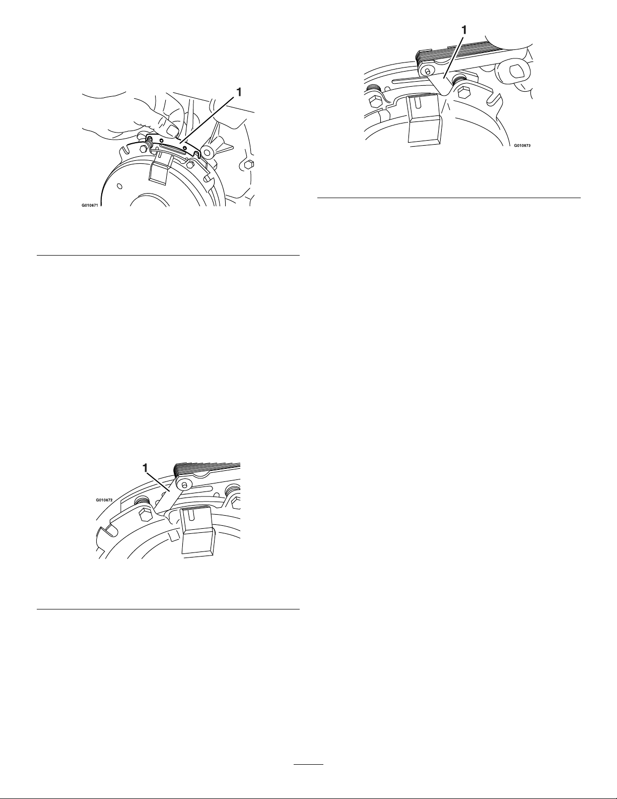
B.Usingneedle-nosepliers,orbyhand,hold
thetabandremovetheshim(Figure70).
Note:Donotdiscardtheshimuntilproper
clutchfunctionhasbeenconrmed.
g010873
Figure72
1.Feelergauge
Figure70
1.Shim
C.Usingapneumaticline,blowoutanydebris
fromunderthebrakepoleandaroundthe
brakespacers.
D.T orqueeachbolt(M6x1)to13N∙m(10
ft-lb)+/-0.7N∙m(0.5ft-lb).
E.Usinga0.25mm(0.01inch)thickfeeler
gauge,verifythatagapispresentbetween
therotorandthearmaturefaceonboth
sidesofthebrakepoleasshowninFigure
71andFigure72.
Note:Duetothewaytherotorandthe
armaturefaceswear(peaksandvalleys)it
issometimesdifculttomeasurethegap
accurately.
g010871
•Ifthegapislessthan0.25mm(0.01
inch),theninstalltheshim;referto
UsingtheClutchShim(page48).
•Ifthegapissufcient,proceedtothe
safetycheckinstepF.
F.Performthefollowingsafetycheck:
i.Sitontheseatandstarttheengine.
ii.Makesurethatthebladesdonot
engagewiththeblade-controlswitch
(PTO)intheOFFposition,andthat
theclutchisdisengaged.
Iftheclutchdoesnotdisengage,
installtheshimagain;refertoUsing
theClutchShim(page48).
iii.Engageanddisengagethe
blade-controlswitch(PTO)10
consecutivetimestoensurethatthe
clutchisfunctioningproperly.
1.Feelergauge
g010872
Figure71
49
Page 50
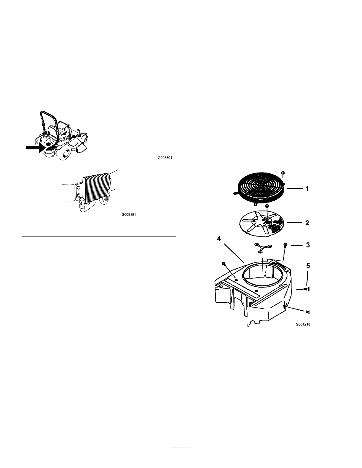
CoolingSystem
Cleaningthe
Maintenance
CleaningtheEngineScreen andEngine-OilCooler
ServiceInterval:Beforeeachuseordaily
Removeanybuildupofgrass,dirt,orotherdebris
fromtheoilcooler(Figure73).
Engine-CoolingFinsand
Shrouds
ServiceInterval:Every100hours/Y early(whichever
comesrst)
1.Disengagetheblade-controlswitch(PTO)and
engagetheparkingbrake.
2.Shutofftheengine,removethekey ,andwait
forallmovingpartstostopbeforeleavingthe
operatingposition.
3.Removetheair-intakescreen,therecoilstarter,
andthefanhousing(Figure74).
4.Cleanthedebrisandgrassfromtheengine
parts.
5.Installtheair-intakescreen,therecoilstarter,
g008804
andthefanhousing(Figure74).
Figure73
Beforeeachuse,removeanybuildupofgrass,dirt,or
otherdebrisfromtheenginescreen.Thiswillhelp
ensureadequatecooling,correcttheenginespeed,
andwillreducethepossibilityofoverheatingand
mechanicaldamagetotheengine(Figure74).
g009191
g004218
Figure74
1.Engineguard4.Fanhousing
2.Engineair-intakescreen
3.Bolt
5.Screw
50
Page 51
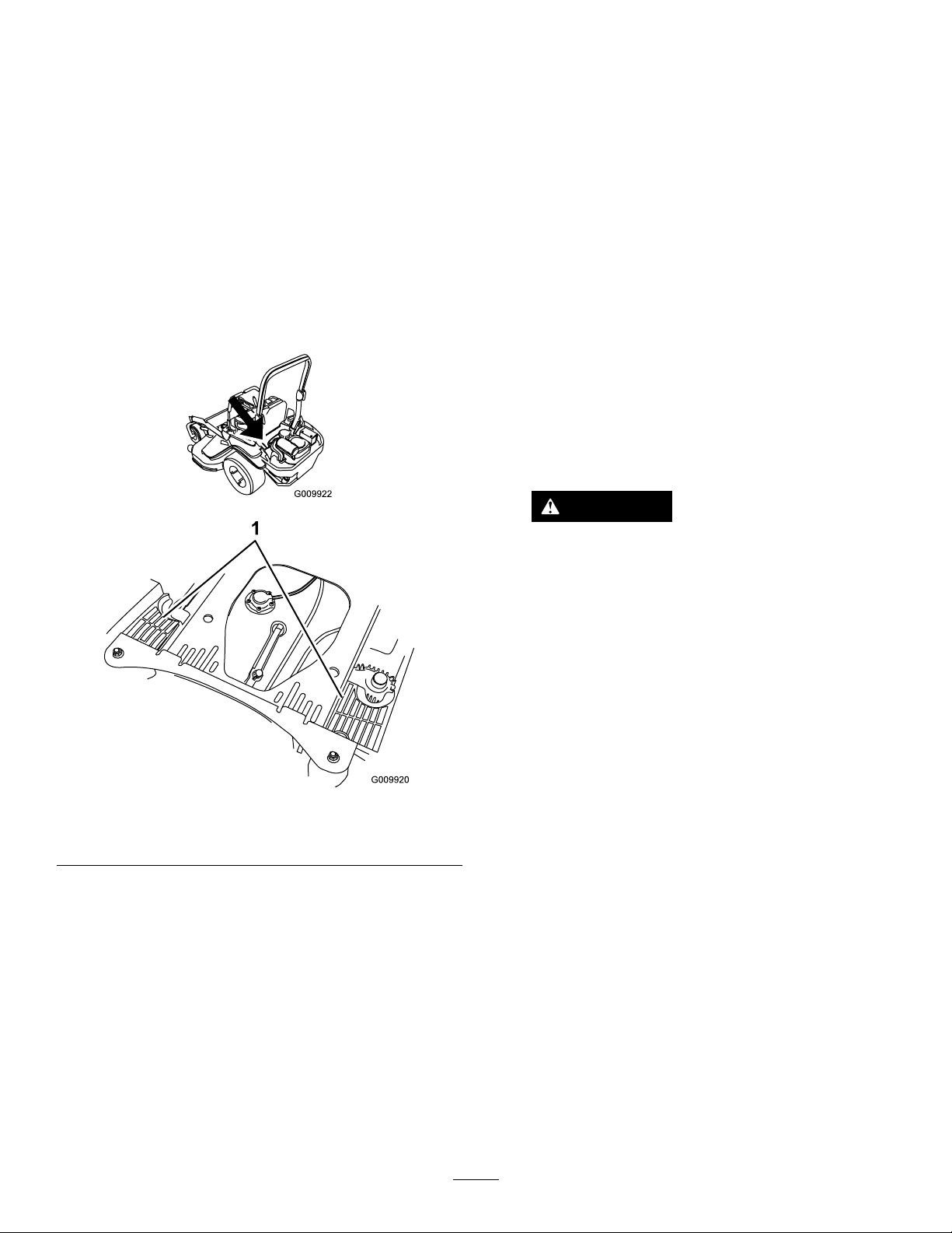
CheckingandCleaningthe Hydraulic-UnitShrouds
BrakeMaintenance
ServiceInterval:Beforeeachuseordaily
1.Disengagetheblade-controlswitch(PTO)and
engagetheparkingbrake.
2.Shutofftheengine,removethekey ,andwait
forallmovingpartstostopbeforeleavingthe
operatingposition.
3.Movetheseatforward.
4.Cleanthedebrisandgrassfromthe
hydraulic-unitshrouds(Figure75).
5.Positiontheseat.
AdjustingtheParking Brake
ServiceInterval:Aftertherst100hours
Every500hoursthereafter
Note:Thisproceduremustbefollowedafterthe
rst100hoursorwhenabrakecomponenthasbeen
removedorreplaced.
1.Drivethemachineontoalevelsurface.
2.Disengagetheblade-controlswitch(PTO),move
themotioncontrolleverstotheNEUTRAL-LOCK
position,andengagetheparkingbrake.
3.Shutofftheengine,waitforallmovingpartsto
stop,andremovethekey .
4.Raisethebackofthemachineandsupportthe
machinewithjackstands.
g009922
DANGER
Mechanicalorhydraulicjacksmayfail
tosupportmachineandcauseaserious
injury.
1.Hydraulic-unitshrouds
Figure75
•Usejackstandswhensupporting
machine.
•Donotusehydraulicjacks.
5.Removethereartiresfromthemachine.
6.Removeanydebrisfromthebrakearea.
7.Rotatethedrive-wheelreleasehandleto
thereleasedposition;refertoUsingthe
g009920
Drive-Wheel-ReleaseValves(page29).
8.Checktoseeifthereisavisiblegapbetween
theL-bracketandthelinkagestop(Figure76).
51
Page 52
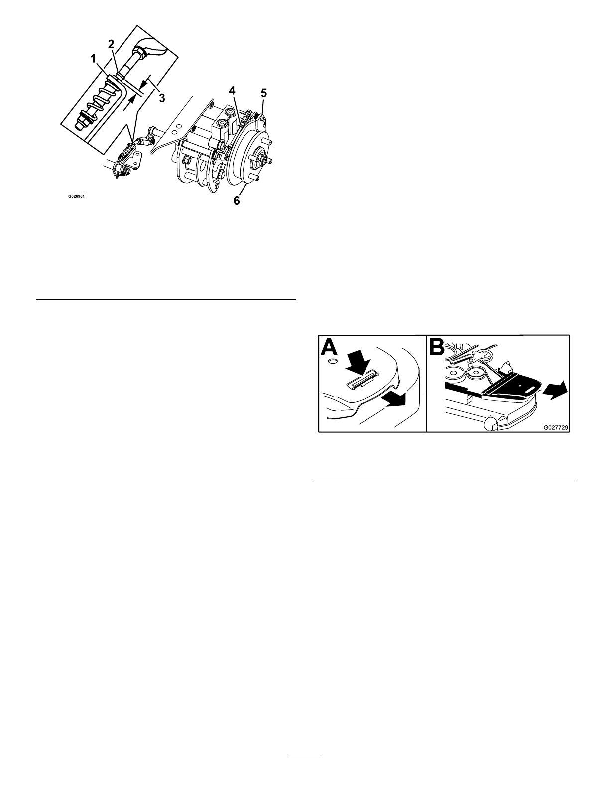
BeltMaintenance
InspectingtheBelts
ServiceInterval:Every50hours
Replacethebeltifitisworn.Thesignsofawornbelt
includesquealingwhilethebeltisrotating;theblades
slippingwhilecuttinggrass;andfrayededges,burn
marks,andcracksonthebelt.
ReplacingtheMowerBelt
Figure76
LeftSideShown
1.L-bracket4.Rearlinkageassembly
2.Linkagestop
3.Gap
9.Disengagetheparkingbrake,thelevershould
beinthedownposition.
10.Turnthewheelhubbyhandinbothdirections
relativetothecaliper;thewheelhubshould
movefreelybetweenthecaliper.
11.Ifagapisneededorthewheelhubdoesnot
movefreely:
A.Disengagetheparkingbrake.
B.Disconnectandne-tunetherearlinkage
assembly:
5.Caliper
6.Wheelhub
•Shortenthelinktocreateagap.
•Lengthenthelinktoallowwheelhub
movement.
C.Connecttherearlinkageassembly.
12.Engagetheparkingbrakeandcheckthegap.
13.Repeatsteps9through13untilavisiblegapis
achievedandthewheelhubrotatesfreely.
14.Repeatthisprocedureforthebrakeonthe
oppositeside.
15.Rotatethedrive-wheelreleasehandleto
theoperatingposition;refertoUsingthe
Drive-Wheel-ReleaseValves(page29).
g026961
1.Disengagetheblade-controlswitch(PTO),move
themotion-controlleverstotheNEUTRAL-LOCK
position,andengagetheparkingbrake.
2.Shutofftheengine,removethekey ,andwait
forallmovingpartstostopbeforeleavingthe
operatingposition.
3.Lowerthemowertothe76mm(3inch)
height-of-cut.
4.Removethebeltcovers(Figure77).
g027729
Figure77
1.Pushthetabdown2.Removethebeltcover
5.Usearatchetinthesquareholeintheidlerarm
toremovetensionontheidlerspring(Figure78).
6.Removethebeltfromthemower-deckpulleys.
7.Removethebeltguideonthespring-loaded
idlerarm(Figure78).
8.Removetheexistingbelt.
9.Installthenewbeltaroundthemowerpulleys
andtheclutchpulleyundertheengine(Figure
78).
16.Installthereartiresandtorquethelugnuts;
refertoCheckingtheWheelLugNuts(page47).
17.Removethejackstands.
52
Page 53
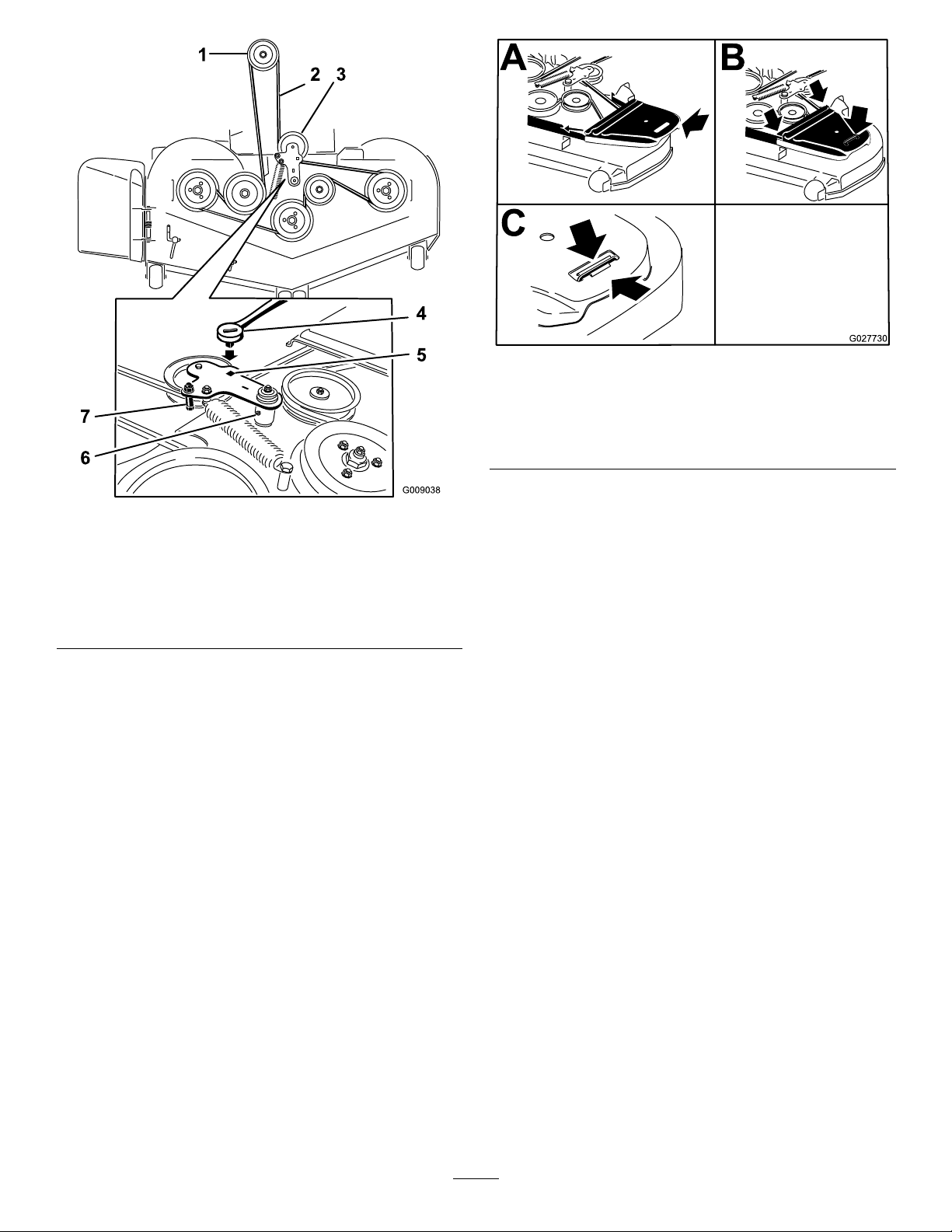
Figure79
g027730
Figure78
1.Clutchpulley5.Squareholeintheidler
2.Mowerbelt
3.Spring-loadedidlerpulley
4.Ratchet
armfortheratchet
6.Idler-greasetting
7.Beltguide
10.Installthebeltguideontheidlerarm(Figure78).
11.Usingtheratchetinthesquarehole,installthe
idlerspring(Figure78).
Note:Makesurethatthespringendsare
seatedintheanchorgrooves.
12.Installthebeltcovers(Figure79).
1.Positionthebeltcover3.Ensurethatthetabis
underthemetalcatch
2.Slidethebeltcoverunder
thesidecatches
g009038
ReplacingtheHydraulic Pump-DriveBelt
1.Disengagetheblade-controlswitch(PTO)and
engagetheparkingbrake.
2.Shutofftheengine,removethekey ,andwait
forallmovingpartstostopbeforeleavingthe
operatingposition.
3.Removethemowerbelt;refertoReplacingthe
MowerBelt(page52).
4.Raisethemachineandsupportitwithjack
stands(Figure80).
53
Page 54
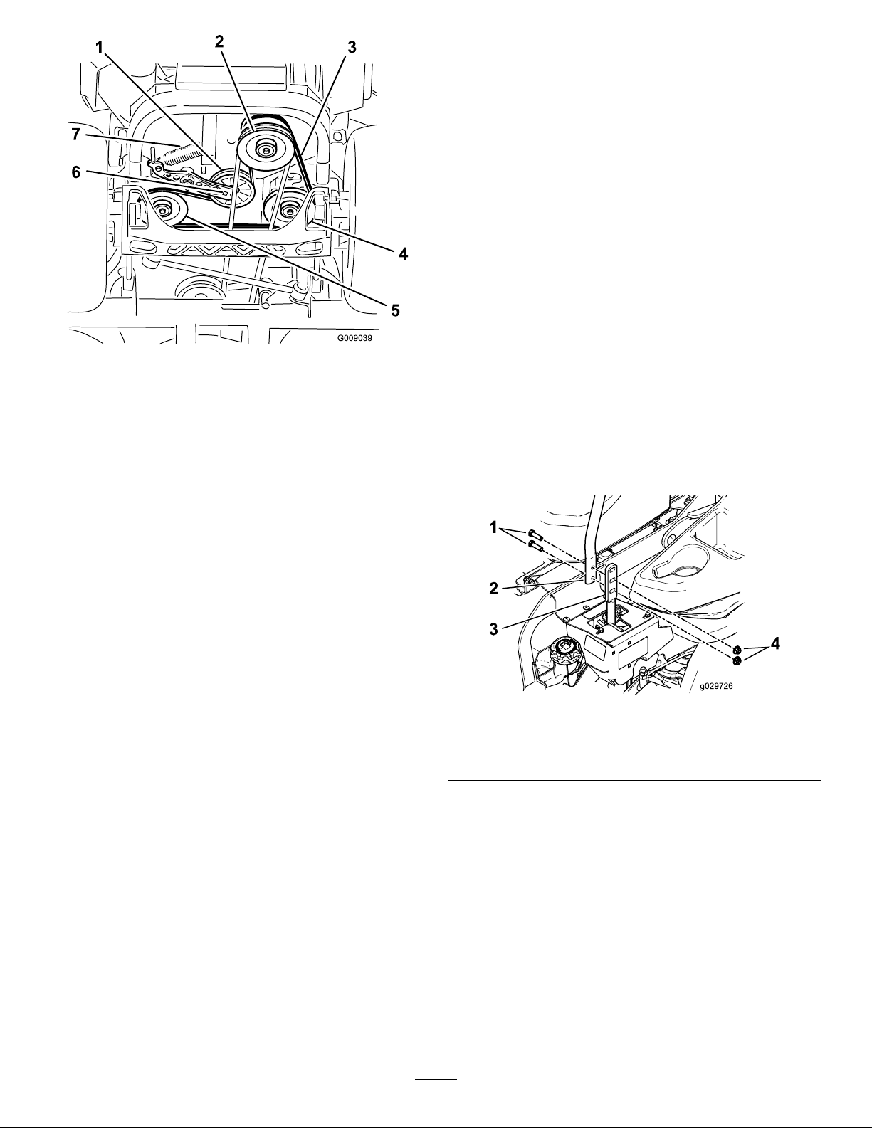
Figure80
1.Idlerpulley
2.Clutchpulley6.Squareholeintheidler
3.Pump-drivebelt7.Idlerspring
4.Righthydraulic-pump
pulley
5.Lefthydraulic-pumppulley
arm
ControlsSystem
Maintenance
Adjustingthe Control-HandlePosition
Thereare2heightpositionsforthecontrol
levers—highandlow.Removetheboltstoadjustthe
heightfortheoperator.
1.Disengagetheblade-controlswitch(PTO),move
themotion-controlleverstotheNEUTRAL-LOCK
position,andengagetheparkingbrake.
2.Shutofftheengine,removethekey ,andwait
g009039
forallmovingpartstostopbeforeleavingthe
operatingposition.
3.Loosentheboltsandangenutsinstalledinthe
levers(Figure81).
4.Aligntheleversinthefront-to-rearpositionby
bringingtheleverstogethertotheNEUTRAL
position,andslidethemuntiltheyarealigned,
thentightenthebolts(Figure82).
5.Usearatchetinthesquareholeintheidlerarm
toremovetheidlerspring(Figure80).
6.Unhooktheidlerspringfromtheframe(Figure
80).
7.Removethebeltfromthehydraulic-unit-drive
pulleysandtheenginepulley.
8.Installthenewbeltaroundenginepulleyand
the2drivepulleys.
9.Usingaratchetinthesquareholeintheidler
arm,installtheidlerspringtotheframe(Figure
80).
10.Installthemowerbelt;refertoReplacingthe
MowerBelt(page52).
Figure81
1.Bolt
2.Handle4.Nut
g029726
3.Controllever
54
Page 55
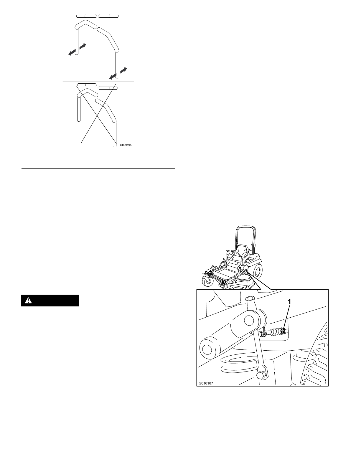
Figure82
5.Iftheendsofthelevershitagainsteachother,
refertoAdjustingtheControl-HandlePosition
(page54).
6.Repeattoadjustthecontrollevers.
Adjustingthe
4.Removetheelectricalconnectionfromtheseat
safetyswitch,locatedunderthebottomcushion
oftheseat.
Note:Theswitchisapartoftheseatassembly.
5.T emporarilyinstallajumperwireacrossthe
terminalsintheconnectorofthemainwire
harness.
6.Starttheengineandrunitatfullthrottleand
disengagethebrake.
Note:Thebrakemustbeengagedandthe
motion-controlleversmustbeouttostart
theengine.Theoperatordoesnothaveto
beintheseat,becauseofthejumperwire
beingused.
7.Runtheunitforatleast5minuteswiththedrive
leversatfullforwardspeedtobringthehydraulic
g009195
uiduptotheoperatingtemperature.
Note:Themotion-controlleversneedsto
beinneutralwhilemakinganynecessary
adjustments.
8.Bringthemotion-controlleversintotheNEUTRAL
position.
9.Adjustthepumpcontrolrodlengthsbyrotating
thedoublenutsontherodintheappropriate
directionuntilthewheelsslightlycreepin
reverse(Figure83).
Motion-ControlLinkage
Locatedoneithersideofthefueltank,belowtheseat
arethepump-controllinkages.Rotatingthepump
linkagewithawrench(1/2inch)allowsnetuning
adjustmentssothatthemachinedoesnotmovein
neutral.Anyadjustmentsshouldbemadeforneutral
positioningonly.
WARNING
Enginemustberunninganddrivewheels
mustbeturningsomotioncontroladjustment
canbeperformed.Contactwithmovingparts
orhotsurfacesmaycausepersonalinjury.
Keepngers,hands,andclothingclearof
rotatingcomponentsandhotsurfaces.
1.Priortostartingtheengine,pushthedeck-lift
pedal,andremovetheheight-of-cutpin.
2.Lowerdecktotheground.
3.Raisetherearofmachineupandsupportitwith
jackstands(orequivalentsupport).
g010187
Figure83
1.Doublenuts
Note:Raisethemachinejusthighenoughto
allowthedrivewheelstoturnfreely.
10.Movethemotion-controlleverstothereverse
positionandwhileapplyingslightpressureto
55
Page 56
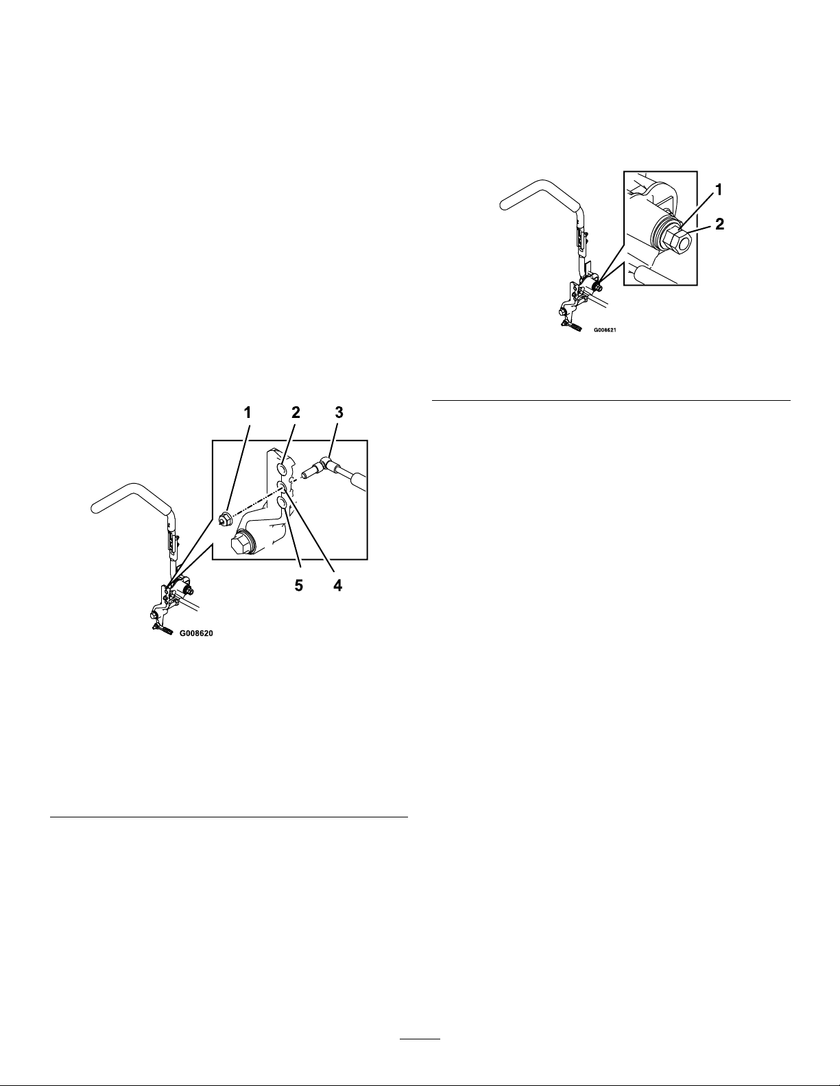
thelever,allowthereverse-indicatorspringsto
bringtheleversbacktoneutral.
Note:Thewheelsmuststopturningorslightly
creepinreverse.
11.Shutofftheunit,removethejumperwirefrom
thewireharness,andplugtheconnectorinto
theseatswitch.
12.Removethejackstands.
13.Raisethedeckandinstalltheheight-of-cutpin.
14.Checkthatthemachinedoesnotcreepin
neutralwiththeparkbrakesdisengaged.
Adjustingthe
1.Loosenthejamnut.
2.Tightenorloosentheangednuttothedesired
feel.
Note:Formoreresistance,tightentheanged
nut.Forlessresistance,loosentheangednut
3.Tightenthejamnut.
Motion-ControlDamper
Youcanadjustthetopdamper-mountingbolttoobtain
amoredesiredmotion-controlleverresistance.See
Figure84formountingoptions.
Figure84
Rightmotioncontrolshown
1.Torquethelocknutto23N∙m(17ft-lb).Theboltmust
protrudepasttheendofthelocknutaftertorquing.
2.Mostresistance(rmestfeel)
3.Damper
4.Mediumresistance(mediumfeel)
5.Leastresistance(softestfeel)
g008621
Figure85
1.Flangednut2.Jamnut
g008620
Adjustingthe Motion-Control Neutral-LockPivot
Youcanadjusttheangednuttoobtainthedesired
motion-controlleverresistancewhenmovingittothe
neutral-lockposition.SeeFigure85foradjustment
options.
56
Page 57
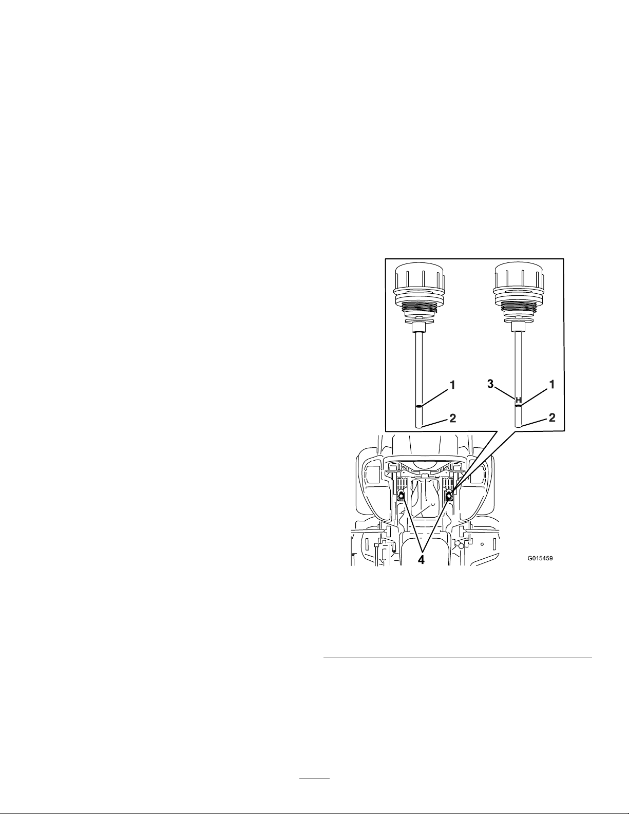
HydraulicSystem
7.Remove1dipstickfromthehydraulicreservoir
(Figure86).
Maintenance
HydraulicSystemSafety
•Ensurethatallhydraulic-uidhosesand
linesareingoodconditionandallhydraulic
connectionsandttingsaretightbefore
applyingpressuretothehydraulicsystem.
•Keepyourbodyandhandsawayfrompinhole
leaksornozzlesthatejecthigh-pressure
hydraulicuid.
•Usecardboardorpapertondhydraulicleaks.
•Safelyrelieveallpressureinthehydraulic
systembeforeperforminganyworkonthe
hydraulicsystem.
•Seekimmediatemedicalattentionifuid
isinjectedintoskin.Injecteduidmustbe
surgicallyremovedwithinafewhoursbya
doctor.
ServicingtheHydraulic
8.Wipethedipstickoffandthreadthedipstickinto
thereservoir.
9.Removethedipstickandlookattheend(Figure
86).
Important:Donotoverllthehydraulic
unitswithoilasdamagemayoccur.Donot
runthemachinewiththeoilbelowtheadd
mark.
10.Iftheoillevelisattheaddmark,slowlypour
onlyenoughoilintothehydraulicreservoirto
raisetheleveltothefullorHline.
11.Installthedipstick.
12.Repeattheprocedurefortheoppositedipstick.
System
Hydraulic-FluidType:T oro
hydraulicuidorMobil
®
®
HYPR-OIL
115W-50.
Important:Usethespecieduid.Otheruids
coulddamagethehydraulicsystem.
EachHydraulicSystemFluidCapacity:1.5L(52
oz)persidewithlterchange
CheckingtheHydraulicFluid
ServiceInterval:Every50hours—Checkthe
hydraulic-uidlevel.
1.Positionthemachineonalevelsurface.
2.Disengagetheblade-controlswitch(PTO),move
themotion-controlleverstotheNEUTRAL-LOCK
position,andengagetheparkingbrake.
3.Shutofftheengine,removethekey ,andwait
forallmovingpartstostopbeforeleavingthe
operatingposition.
4.Allowtheengineandthehydraulicsystemto
coolfor10minutes.
™
500
g015459
Figure86
Eitherdipstickisusedinthemachine
1.Full3.H—meanshighlevel
2.Add4.Dipsticklocationsunder
seat
Note:Theoillevelonthedipstickisincorrect
whentheoilischeckedandtheunitishot.
5.Movetheseatforward.
6.Cleantheareaaroundthedipsticksof
hydraulic-systemreservoirs(Figure86).
57
Page 58
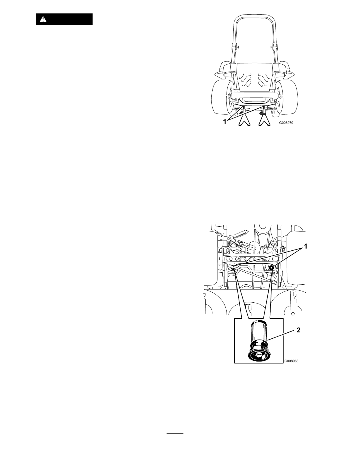
WARNING
Hydraulicuidescapingunderpressure
canpenetrateskinandcauseinjury .
•Ifhydraulicuidisinjectedintothe
skinitmustbesurgicallyremoved
withinafewhoursbyadoctorfamiliar
withthistypeofinjury.Gangrenemay
resultifthisisnotdone.
•Keepyourbodyandhandsawayfrom
pinholeleaksornozzlesthateject
high-pressurehydraulicuid.
•Usecardboardorpapertond
hydraulicleaks.
•Safelyrelieveallpressureinthe
hydraulicsystembeforeperforming
anyworkonthehydraulicsystem.
g008970
Figure87
1.Jackstands
•Makesurethatallhydraulic-oilhoses
andlinesareingoodcondition,and
allhydraulicconnectionsandttings
aretightbeforeapplyingpressureto
thehydraulicsystem.
ReplacingtheHydraulicFluidand Filters
ServiceInterval:Aftertherst250hours—Change
thehydraulicltersandhydraulic
uidwhenusinganytypeofuid.
Every250hours—Changethehydrauliclters
andhydraulicuidwhenusingMobil
(moreoftenindirtyordustyconditions).
Every500hours—Changethehydraulic
ltersandhydraulicuidwhenusingT oro
HYPR-OIL
dirtyordustyconditions).
Toreplacethehydraulicuid,theltersneedtobe
removed.Replacebothatthesametime;referto
ServicingtheHydraulicSystem(page57)fortheoil
specications.
™
500hydraulicuid(moreoftenin
®
1uid
4.Removeboththemowerbeltandthepump-drive
belt;refertoReplacingtheMowerBelt(page
52)andReplacingtheHydraulicPump-Drive
Belt(page53).
Note:Thispreventsoilfromgettingonthe
belts.
5.Placeadrainpanunderthelter,removethe
oldlter,andwipethesurfaceclean(Figure88).
®
1.Disengagetheblade-controlswitch(PTO),move
themotion-controlleverstotheNEUTRAL-LOCK
position,andengagetheparkingbrake.
2.Shutofftheengine,removethekey ,andwait
forallmovingpartstostopbeforeleavingthe
operatingposition.
3.Raisethemachineandsupportitwithjack
stands(Figure87).
Figure88
Bottomviewofthemachine
1.Filterlocations
6.Applyathincoatofhydraulicuidtotherubber
gasketonthereplacementlter(Figure88).
58
2.Hydrauliclter
g008968
Page 59

7.Installthereplacementhydrauliclter.
8.Installthepump-drivebeltandthemowerbelt.
9.Removethejackstandsandlowerthemachine
(Figure87).
MowerDeck Maintenance
10.Addoiltothehydraulicreservoirandcheckfor
anyleaks.
11.Cleanupanyspilledoil.
12.Starttheengineandletitrunforabout2minutes
topurgeairfromthesystem.
13.Shutofftheengineandcheckforleaks.
14.Checktheoillevelwhiletheoiliscold.
15.Ifrequired,addoiltothehydraulicreservoir.
Note:Donotoverll.
LevelingtheMowerDeck
SettinguptheMachine
Note:Ensurethatthemowerdeckislevelbefore
matchingtheheightofcut(HOC).
1.Positionthemoweronaatsurface.
2.Disengagetheblade-controlswitch(PTO),move
themotion-controlleverstotheNEUTRAL-LOCK
position,andengagetheparkingbrake.
3.Shutofftheengine,removethekey ,andwait
forallmovingpartstostopbeforeleavingthe
operatingposition.
4.Checktirepressureofthedrivetires.
5.Ifneeded,adjustto90kPa(13psi).
6.Positionthemowertothe76mm(3inches)
height-of-cutposition.
LevelingtheDeck
1.Positionthemoweronaatsurface.
2.Shutofftheengine,waitforallmovingpartsto
stop,removethekey,andengageparkingbrake.
3.Checkthetirepressureinthedrivetiresand
adjustifnecessary.
Note:Properinationpressurefortiresis90
kPa(13psi).
4.Positionthetransportlockinthelatching
position.
5.Pushthedeck-liftpedalallthewayforwardand
thedeckwilllatchatthe14cm(5–1/2inch)
TRANSPORTposition(Figure89).
59
Page 60
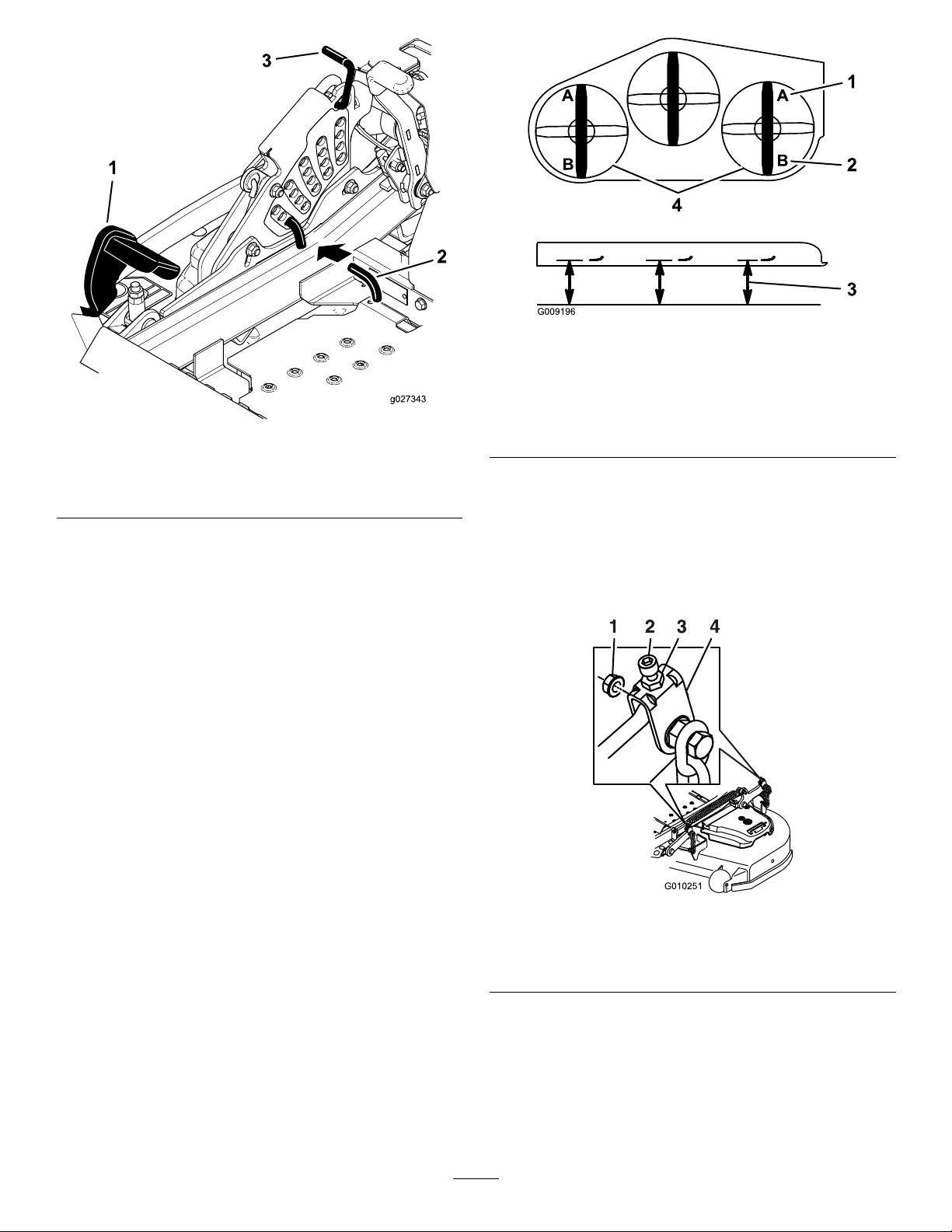
Figure90
g009196
Figure89
1.Deck-liftpedal
2.Height-of-cutpin
3.Transportlock
6.Inserttheheight-adjustmentpinintothe7.6cm
(3inch)cutting-heightposition.
7.Releasethetransportlockandallowthedeckto
lowertothecuttingheight.
8.Raisethedischargechute.
9.Onbothsidesofthedeck,measurefromthe
levelsurfacetothefronttipoftheblade(Position
A);refertoFigure90.
Note:Themeasurementshouldread7.6mm
(3inches).
1.7.6cm(3inches)at
positionAiscorrect
g027343
2.8.3cm(3–1/4inches)at
positionBiscorrect
3.Measurehere,fromthe
bladetip,tothehard
surface
4.MeasureatpositionAand
Bonbothsides
10.Ifneeded,loosentheangedlocknutontheside
oftheyokeandthejamnutontop.Fine-tune
theadjusterscrewbyturningittoget7.6mm(3
inch)height(Figure91).
Note:Toincreasetheheight,turntheadjuster
screwclockwise;todecreasetheheight,turnit
counterclockwise.
Figure91
1.Flangedlocknut3.Jamnut
2.Adjusterscrew4.Yoke
11.Ifthefrontdecklinksdonothaveenough
adjustmenttoachievetheaccuratecutheight,
youcanusethesinglepointadjustmentcanbe
utilizedtogainmoreadjustment.
12.T oadjustthesinglepointsystem,loosenthe2
boltsatthebottomoftheheight-of-cutplate.
RefertoFigure92.
60
g010251
Page 61
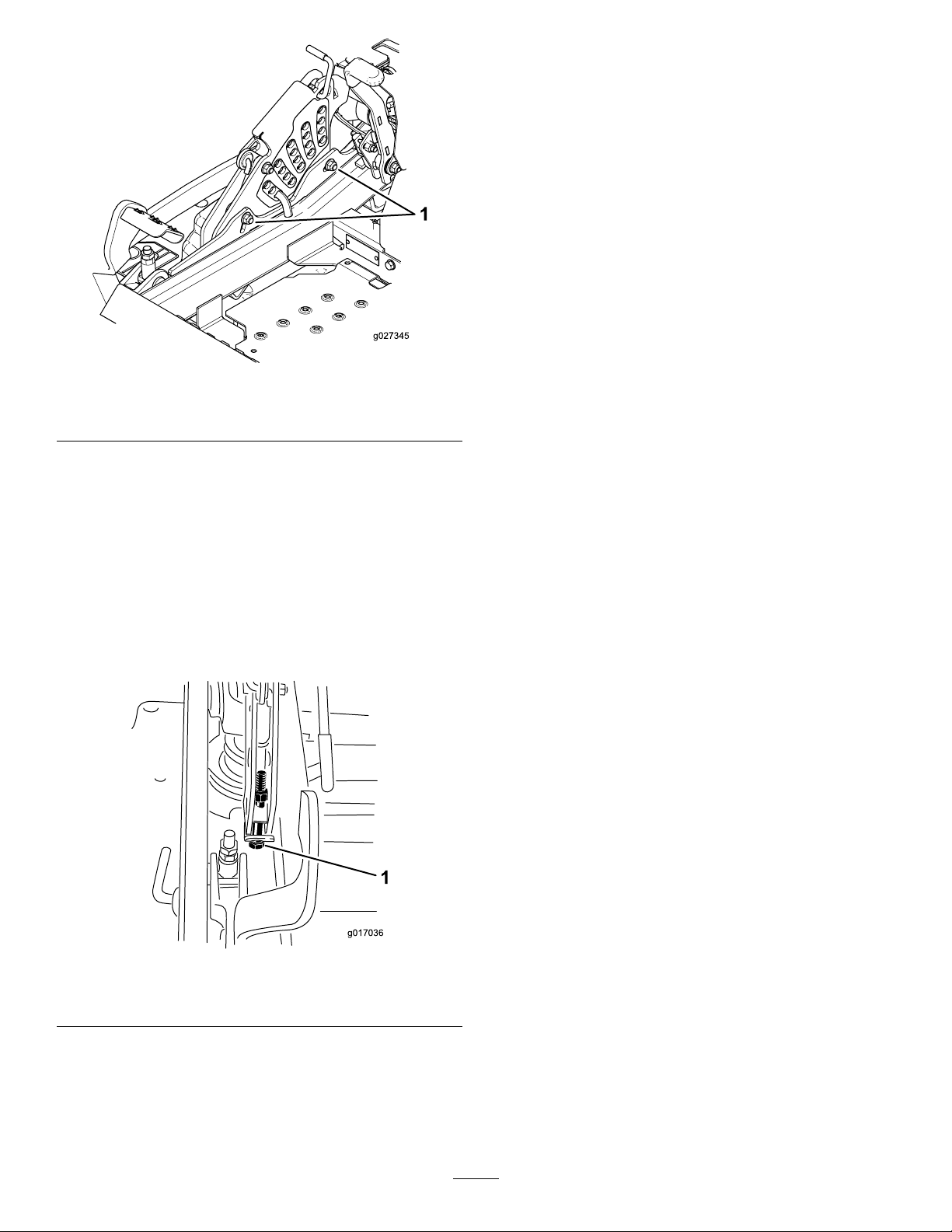
15.Onbothsidesofthedeck,measurefromthe
levelsurfacetothebacktipoftheblade(Postion
B).Themeasurementshouldread8.3cm(3-1/4
inches);refertoFigure90.
16.Fine-tunetheadjusterscrewbyturningittoget
8.3mm(3–1/4inches)height(Figure91).
Toincreasetheheight,turntheadjustmentnut
clockwise;todecreasetheheight,turnthenut
counterclockwise.
17.Measureuntilall4sidesarethecorrectheight.
Tightenallthejamnutsonthedeck-liftarm
assemblies.
18.Lowerthedischargechute.
Figure92
1.Boltsatthebottomoftheheight-of-cutplate
13.Ifthedeckistoolow,tightenthe
single-point-adjustmentboltbyrotatingit
clockwise.Ifthedeckistoohigh,loosen
thesingle-point-adjustmentboltbyrotatingit
counterclockwise(Figure93).
Note:Loosenortightenthe
single-point-adjustmentboltenoughto
movetheheight-of-cutplate-mountingboltsat
least1/3thelengthoftheavailabletravelin
theirslots.Thiswillregainsomeup-and-down
adjustmentoneachofthe4decklinks.
g027345
ServicingtheCutting Blades
Toensureasuperiorqualityofcut,keeptheblades
sharp.Forconvenientsharpeningandreplacement,
youmaywanttokeepextrabladesonhand.
BladeSafety
Awornordamagedbladecanbreak,andapieceof
thebladecouldbethrowntowardyouorbystanders,
resultinginseriouspersonalinjuryordeath.Tryingto
repairadamagedblademayresultindiscontinued
safetycerticationoftheproduct.
•Inspectthebladesperiodicallyforwearordamage.
•Usecarewhencheckingtheblades.Wrapthe
bladesorweargloves,andusecautionwhen
servicingtheblades.Onlyreplaceorsharpenthe
blades;neverstraightenorweldthem.
•Onmulti-bladedmachines,takecareasrotating1
bladecancauseotherbladestorotate.
Figure93
1.Single-point-adjustmentbolt
14.T orquethe2boltsatthebottomofthe
height-of-cutplate(Figure92)to37to45N∙m
(27to33ft-lb).
Note:Formostconditions,adjusttheback
bladetip6.4mm(1/4inch)higherthanthefront.
BeforeInspectingorServicingthe Blades
1.Parkthemachineonalevelsurface,disengage
theblade-controlswitch(PTO),andengagethe
parkingbrake.
g017036
2.Shutofftheengine,removethekey,and
disconnectthespark-plugwiresfromthespark
plugs.
61
Page 62
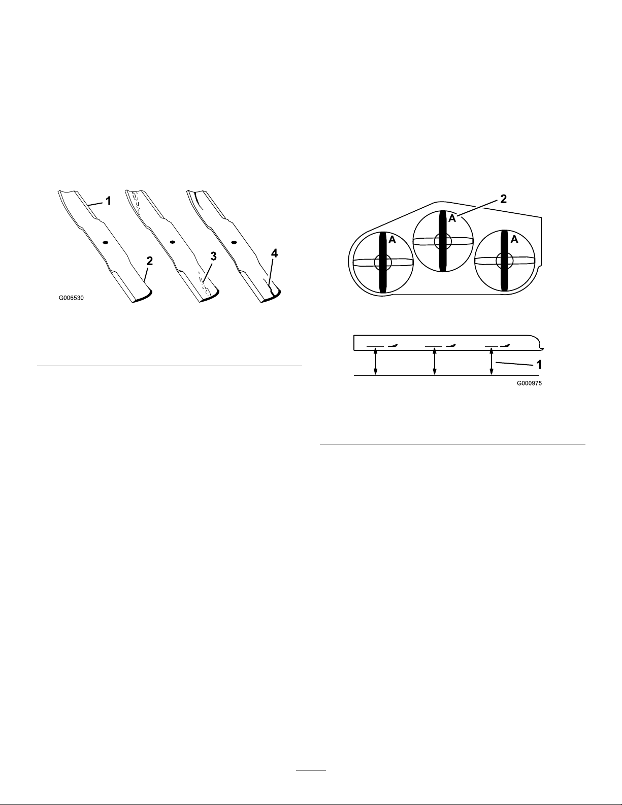
InspectingtheBlades
CheckingforBentBlades
ServiceInterval:Beforeeachuseordaily
1.Inspectthecuttingedges(Figure94).
2.Iftheedgesarenotsharporhavenicks,remove
andsharpentheblade;refertoSharpeningthe
Blades(page63).
3.Inspecttheblades,especiallyinthecurvedarea.
4.Ifyounoticeanycracks,wear,oraslotforming
inthisarea,immediatelyinstallanewblade
(Figure94).
Figure94
1.Cuttingedge3.Wear/slotforming
2.Curvedarea4.Crack
1.Disengagetheblade-controlswitch(PTO),move
themotion-controlleverstotheNEUTRAL-LOCK
position,andengagetheparkingbrake.
2.Shutofftheengine,removethekey ,andwait
forallmovingpartstostopbeforeleavingthe
operatingposition.
3.Rotatethebladesuntiltheendsfaceforward
andbackward.
4.Measurefromalevelsurfacetothecutting
edge,positionA,oftheblades(Figure95).
g006530
Figure95
1.Measureherefromblade
tohardsurface
2.PositionA
5.Rotatetheoppositeendsofthebladesforward.
6.Measurefromalevelsurfacetothecuttingedge
ofthebladesatthesamepositionasinstep4
above.
Note:Thedifferencebetweenthedimensions
obtainedinsteps4and6mustnotexceed3
mm(1/8inch).
Note:Ifthisdimensionexceeds3mm(1/8
inch),thebladeisbentandmustbereplaced.
g000975
62
Page 63
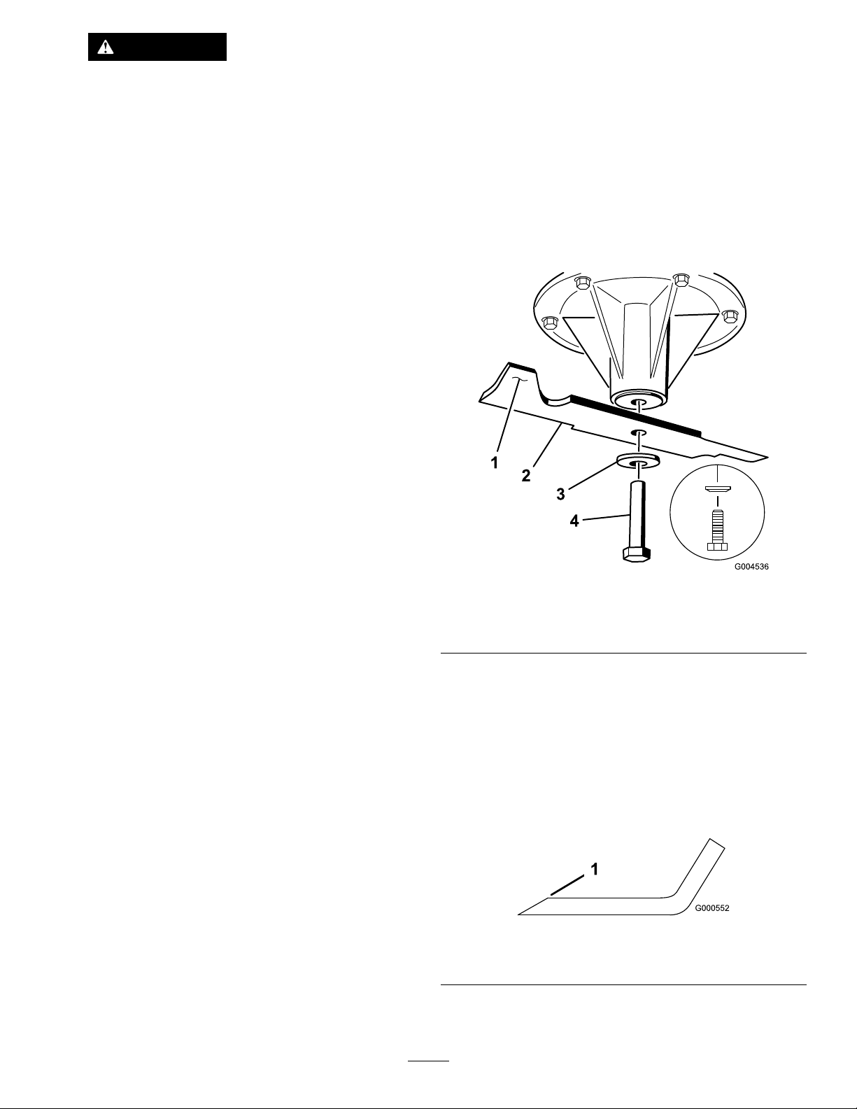
WARNING
Abladethatisbentordamagedcould
breakapartandcouldseriouslyinjureor
killyouorbystanders.
•Alwaysreplaceabentordamaged
bladewithanewblade.
•Donotleorcreatesharpnotchesin
theedgesorsurfacesoftheblade.
RemovingtheBlades
Bladesmustbereplacedifasolidobjectishit,ifthe
bladeisoutofbalance,orifthebladeisbent.T o
ensureoptimumperformanceandcontinuedsafety
conformanceofthemachine,usegenuineToro
replacementblades.Replacementbladesmadeby
othermanufacturersmayresultinnonconformance
withsafetystandards.
1.Holdthebladeendusingaragora
thickly-paddedglove.
2.Removethebladebolt,thecurvedwasher,and
thebladefromthespindleshaft(Figure96).
Figure96
1.Sailareaoftheblade3.Curvedwasher
2.Blade4.Bladebolt
SharpeningtheBlades
1.Usealetosharpenthecuttingedgeatboth
endsoftheblade(Figure97).
Note:Maintaintheoriginalangle.
Note:Thebladeretainsitsbalanceifthesame
amountofmaterialisremovedfrombothcutting
edges.
Figure97
1.Sharpenatoriginalangle.
g004536
g000552
2.Checkthebalanceofthebladebyputtingitona
bladebalancer(Figure98).
63
Page 64
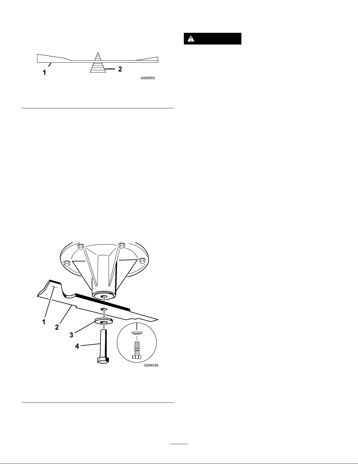
Note:Ifthebladestaysinahorizontalposition,
thebladeisbalancedandcanbeused.
RemovingtheMowerDeck
Note:Ifthebladeisnotbalanced,lesome
metalofftheendofthesailareaonly(Figure97).
Figure98
1.Blade2.Balancer
3.Repeatthisprocedureuntilthebladeis
balanced.
InstallingtheBlades
1.Installthebladeontothespindleshaft(Figure
99).
Important:Thecurvedpartoftheblade
mustbepointingupwardtowardtheinside
ofthemowertoensurepropercutting.
2.Installthespringdiskandbladebolt(Figure99).
Note:Thespring-diskconemustbeinstalled
towardthebolthead(Figure99).
3.T orquethebladeboltto1 15to150N∙m(85to
110ft-lb).
WARNING
Deckliftarmassemblieshavestoredenergy.
Removingthedeckwithoutreleasingthe
storedenergycancauseseriousinjuryor
death.
g000553
Donotattempttodisassemblethedeckfrom
thefrontframewithoutlockingoutthestored
energy.
Beforeservicingorremovingthemowerdeck,lock
outthespring-loadeddeckarms.
1.Shutofftheengine,waitforallmovingpartsto
stop,andremovethekey.Engagetheparking
brake.
2.Removetheheight-adjustmentpinandlower
thedecktotheground.
3.Placetheheight-adjustmentpininthe7.6cm(3
inch)cutting-heightlocation.
4.Removethebeltcovers.
5.Liftuptheoorpanandinsertaratchetintothe
squareholeinthedeckidler(Figure100).
6.Rotatethedeckidlerclockwiseandremovethe
mowerbelt(Figure100).
Figure99
1.Sailareaoftheblade3.Springdisk
2.Blade4.Bladebolt
g004536
64
Page 65
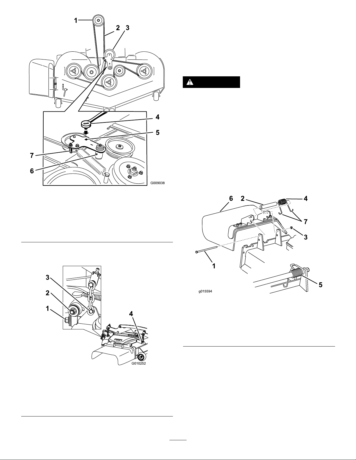
Figure100
8.Raisethedeckstrutsandsecurethemintheup
position.Slidethedeckouttotherightsideof
themachine.
ReplacingtheGrass
Deector
WARNING
Operatingthemachinewiththeengine
runningataspeedgreaterthanthefactory
settingcancausethemachinetothrowapart
ofthebladeorengineatyouorbystanders,
resultinginseriousinjuryordeath.
Donotoperatethemachineunlessyouinstall
acoverplate,mulchplate,grassdeector,or
bagger.
1.Removethelocknut,bolt,spring,andspacer
holdingthedeectortothepivotbrackets
(Figure102).Removethedamagedorworn
g009038
grassdeector.
1.Clutchpulley5.Squareholeintheidler
2.Mowerbelt
3.Spring-loadedidlerpulley
4.Ratchet
armfortheratchet
6.Idlergreasetting
7.Beltguide
7.Removeandretainthehardwareonbothsides
ofthedeckasshowninFigure101.
Figure101
1.Rightstabilizer
2.Deckstrut(rightsideshown)
3.Removethereardeckliftattachmentshoulderboltandnut.
4.Removethefrontdeckliftattachmentshoulderboltandnut.
g015594
Figure102
1.Bolt
2.Spacer6.Grassdeector
3.Locknut
4.Spring
5.Springinstalled
7.Jhookendofspring
2.Placethespacerandthespringontothegrass
deector.PlaceoneJendofthespringbehind
g010252
thedeckedge.
Note:MakesureoneJendofthespringis
installedbehindthedeckedgebeforeinstalling
theboltasshowninFigure102.
3.Installtheboltandthenut.PlaceoneJhook
endofthespringaroundthegrassdeector
(Figure102).
65
Page 66

Important:Thegrassdeectormustbeable
torotate.Liftthedeectoruptothefullopen
positionandensurethatitrotatesintothe
fulldownposition.
Cleaning
CleaningundertheMower
ServiceInterval:Beforeeachuseordaily
1.Disengagetheblade-controlswitch(PTO),move
themotion-controlleverstotheNEUTRAL-LOCK
position,andengagetheparkingbrake.
2.Shutofftheengine,removethekey ,andwait
forallmovingpartstostopbeforeleavingthe
operatingposition.
3.Raisethemowertothetransportposition.
DisposingofWaste
Engineoil,batteries,hydraulicoil,andenginecoolant
arepollutantstotheenvironment.Disposeofthese
accordingtoyourstateandlocalregulations.
66
Page 67

Storage
CleaningandStoringthe Machine
1.Disengagetheblade-controlswitch(PTO),
engagetheparkingbrake,turntheignitionkey
totheOFFposition,andremovethekey.
2.Removegrassclippings,dirt,andgrime
fromtheexternalpartsoftheentiremachine
(especiallytheengineandhydraulicsystem).
Cleandirtandchafffromtheoutsideofthe
engine-cylinder-headnsandtheblower
housing.
Important:Youcanwashthemachine
withmilddetergentandwater.Donot
pressure-washthemachine.Avoid
excessiveuseofwater,especiallynearthe
controlpanel,engine,hydraulicpumps,and
motors.
3.Checkthebrake;refertoOperatingtheParking
Brake(page20).
4.Servicetheaircleaner;refertoServicingtheAir
Cleaner(page36).
5.Greasethemachine;refertoGreasingthe
Mower(page34).
Note:Afuelstabilizer/conditionerismost
effectivewhenmixedwithfreshfueland
usedatalltimes.
B.Runtheenginetodistributeconditionedfuel
throughthefuelsystem(5minutes).
C.Shutofftheengine,allowittocool,and
drainthefueltank;refertoServicingthe
FuelT ank(page42).
D.Starttheengineandrunituntilitstops.
E.Disposeoffuelproperly.Recycleasper
localcodes.
Important:Donotstore
stabilizer/conditionedfuelover
90days.
13.Checkandtightenallbolts,nuts,andscrews.
Repairorreplaceanypartthatisdamaged.
14.Paintallscratchedorbaremetalsurfaces.Paint
isavailablefromyourAuthorizedServiceDealer.
15.Storethemachineinaclean,drygarageor
storagearea.
16.Removethekeyfromtheignitionswitch
andkeepitoutofreachofchildrenorother
unauthorizedusers.
17.Coverthemachinetoprotectitandkeepitclean.
6.Changethecrankcaseoil;refertoServicingthe
EngineOil(page37).
7.Checkthetirepressure;refertoCheckingthe
TirePressure(page46).
8.Changethehydrauliclters;refertoServicing
theHydraulicSystem(page57).
9.Chargethebattery;refertoChargingtheBattery
(page44).
10.Scrapeanyheavybuildupofgrassanddirt
fromtheundersideofthemower,thenwashthe
mowerwithagardenhose.
Note:Runthemachinewiththeblade-control
switch(PTO)engagedandtheengineathigh
idlefor2to5minutesafterwashing.
11.Checktheconditionoftheblades;referto
ServicingtheCuttingBlades(page61).
12.Preparethemachineforstoragewhennon-use
occursover30days.Preparethemachinefor
storageasfollows:
A.Addapetroleumbased
stabilizer/conditionertofuelinthe
tank.Followmixinginstructionsfrom
thestabilizermanufacturer.Donotuse
analcoholbasedstabilizer(ethanolor
methanol).
67
Page 68

Troubleshooting
Problem
Thestarterdoesnotcrank.
Theenginedoesnotstart,startshard,or
failstokeeprunning.
PossibleCauseCorrectiveAction
1.Theblade-controlswitch(PTO)is
engaged.
2.Theparkingbrakeisnoton.2.Engagetheparkingbrake.
3.Themotion-controlleversarenotin
theneutral-lockposition.
4.Theoperatorisnotseated.
5.Thebatteryisdead.
6.Theelectricalconnectionsare
corrodedorloose.
7.Thefuseisblown.7.Replacethefuse.
8.Therelayorswitchiswornor
damaged.
1.Thefueltankisempty.1.Fillthefueltank.
2.Thefuel-shutoffvalveisclosed.2.Openthefuel-shutoffvalve.
3.Theoillevelinthecrankcaseislow.3.Addoiltothecrankcase.
4.Thethrottleisnotinthecorrect
position.
5.Thereisdirtinthefuellter.5.Replacethefuellter.
6.Thereisdirt,water,orstalefuelinthe
fuelsystem.
7.Theaircleanerisdirty.
8.Theseatswitchisnotfunctioning
properly.
9.Theelectricalconnectionsare
corroded,loose,ordamaged.
10.Therelayorswitchiswornor
damaged.
11.Thesparkplugisfouledorimproperly
gapped.
12.Thespark-plugwireisnotconnected.
1.Movetheblade-controlswitch(PTO)
tothedisengagedposition.
3.Ensurethatthemotion-controllevers
areintheneutral-lockposition.
4.Sitontheseat.
5.Chargethebattery.
6.Checktheelectricalconnectionsfor
goodcontact.
8.ContactanAuthorizedServiceDealer.
4.Besurethatthethrottlecontrolis
midwaybetweentheslowandfast
positions.
6.ContactanAuthorizedServiceDealer.
7.Cleanorreplacetheair-cleaner
element.
8.Checktheseat-switchindicator.
Replacetheseatifnecessary .
9.Checktheelectricalconnections
forgoodcontact.Cleanthe
connectorterminalsthoroughlywith
electrical-contactcleaner,apply
dielectricgrease,andmakethe
appropriateconnections.
10.ContactanAuthorizedServiceDealer.
11.Adjustorreplacethesparkplug.
12.Checkthespark-plugwireconnection.
Theenginelosespower.
Theengineoverheats.
Themowerpullstotheleftorright(with
leversfullyforward).
1.Theengineloadisexcessive.1.Reducethegroundspeed.
2.Theaircleanerisdirty.
3.Theoillevelinthecrankcaseislow.3.Addoiltothecrankcase.
4.Thecoolingnsandtheairpassages
abovetheengineareplugged.
5.Theventholeinthefuelcapisplugged.5.Cleanorreplacethefuelcap.
6.Thereisdirtinthefuellter.6.Replacethefuellter.
7.Thereisdirt,water,orstalefuelinthe
fuelsystem.
1.Theengineloadisexcessive.1.Reducethegroundspeed.
2.Theoillevelinthecrankcaseislow.2.Addoiltothecrankcase.
3.Thecoolingnsandtheairpassages
abovetheengineareplugged.
1.Thetrackingneedsadjustment1.Adjustthetracking.
2.Thetirepressureinthedrivetiresis
notcorrect.
2.Cleantheair-cleanerelement.
4.Removetheobstructionfromthe
coolingnsandtheairpassages.
7.ContactanAuthorizedServiceDealer.
3.Removetheobstructionfromthe
coolingnsandtheairpassages.
2.Adjustthetirepressureinthedrive
tires.
68
Page 69

Problem
PossibleCauseCorrectiveAction
Themachinedoesnotdrive.
Themachinevibratesabnormally .
Themachineproducesanunevencutting
height.
1.Thebypassvalvesarenotclosedtight.1.Tightenthebypassvalves.
2.Thepumpbeltisworn,loose,or
broken.
3.Thepumpbeltisoffapulley.3.Changethebelt.
4.Theidlerspringisbrokenormissing.4.Replacethespring.
5.Thehydraulicoillevelislowortoohot.5.Addhydraulicoiltothereservoirsor
1.Thecuttingblade(s)is/arebentor
unbalanced.
2.Theblademountingboltisloose.2.Tightentheblademountingbolt.
3.Theenginemountingboltsareloose.3.Tightentheenginemountingbolts.
4.Theenginepulley ,idlerpulley,orblade
pulleyisloose.
5.Theenginepulleyisdamaged.
6.Thebladespindleisbent.
7.Themotormountislooseorworn.
1.Theblade(s)is/arenotsharp.1.Sharpentheblade(s).
2.Thecuttingblade(s)is/arebent.2.Installnewcuttingblade(s).
3.Themowerdeckisnotlevel.
4.Theundersideofmowerisdirty.4.Cleantheundersideofthemower.
5.Thetirepressureisnotcorrect.5.Adjustthetirepressure.
6.Thebladespindleisbent.
2.Changethebelt.
letitcooldown.
1.Installnewcuttingblade(s).
4.Tightentheappropriatepulley.
5.ContactanAuthorizedServiceDealer.
6.ContactanAuthorizedServiceDealer.
7.ContactanAuthorizedServiceDealer.
3.Levelthemowerdeckfromside-to-side
andfront-to-rear.
6.ContactanAuthorizedServiceDealer.
Thebladesdonotrotate.
Theclutchdoesnotengage.
1.Themowerdeckbeltisworn,loose,
orbroken.
2.Themowerdeckbeltisoffpulley.
3.Thepumpdrivebeltisworn,loose,or
broken.
4.Theidlerspringisbrokenormissing.4.Replacethespring.
1.Thefuseisblown.
2.Thereislowvoltagesupplyatthe
clutch.
3.Thecoilisdamaged.3.Replacetheclutch.
4.Thereisinadequatecurrentsupply.4.Repairorreplacetheclutchlead
5.Therotor/armatureairgapistoolarge.
1.Installanewdeckbelt.
2.Installthemowerdeckpulleyand
checktheidlerpulley,idlerarm,and
springforcorrectpositionandfunction.
3.Checkthebelttensionorinstallanew
belt.
1.Replacethefuse.Checkthecoil
resistance,batterycharge,charging
system,andwiringconnections,and
replacecomponentsifnecessary.
2.Checkthecoilresistance,battery
charge,chargingsystem,andwiring
connectionsandreplacepartsif
necessary.
wireorelectricalsystem.Cleanthe
connectorcontacts.
Removetheshimorreplacetheclutch.
5.
69
Page 70
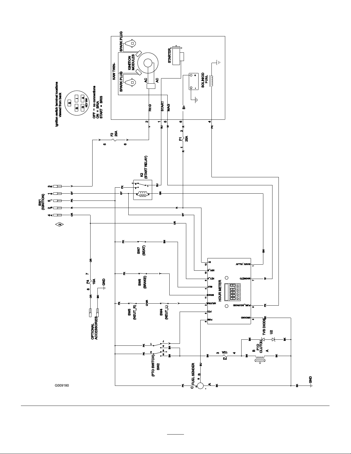
Schematics
WireDiagram(Rev .A)
70
g009180
Page 71

Notes:
Page 72

TheToroWarranty
ALimitedWarranty(seewarrantyperiodsbelow)Contractor
Landscape
Equipment(LCE)
RidingProduct
ConditionsandProductsCovered
TheToroCompanyanditsafliate,ToroWarrantyCompany,pursuanttoanagreement
betweenthem,jointlypromisetorepairtheT oroProductslistedbelowifdefectivein
materialsorworkmanship.
Thefollowingtimeperiodsapplyfromtheoriginaldateofpurchase:
ProductsWarrantyPeriod
GrandStand
•Engines
ZMaster
•Engines
ZMaster
•Engines
ZMaster
•Engines
ZMaster
•Engines
ZMaster
•Engines
TITANHD1500Series
3
®
3
®
3
®
3
®
7000SeriesMowers
3
®
8000SeriesMowers
3
®
3000SeriesMowers
5000SeriesMowers
6000SeriesMowers
Mowers
5yearsor1,200hours
3years
5yearsor1,250hours
3years
5yearsor1,250hours
3years
5yearsor1,250hours
3years
4yearsor1,200hours
2years
2years
3years
4yearsor500Hours
2
2
2
2
2
2
•EnginesToro–4yearsor500hours
TITANHD2000Series
•Engines
TITANHD2500Series
•Engines
3
Kohler–3years
4yearsor1000Hours
4yearsor750Hours
3
Kawasaki–3years
2
2
AllMowers
•Battery90daysPartsandLabor
1yearPartsonly
•BeltsandTires90days
•Attachments1year
1
Residentialusemeansuseoftheproductonthesamelotasyourhome.Useatmorethanone
locationisconsideredcommercialuseandthecommercialwarrantywouldapply .
2
Whicheveroccursrst.
3
SomeenginesusedonT oroProductsarewarrantedbytheenginemanufacturer .
OwnerResponsibilities
YoumustmaintainyourT oroProductbyfollowingthemaintenanceprocedures
describedintheOperator'sManual.Suchroutinemaintenance,whetherperformedby
adealerorbyyou,isatyourexpense.
InstructionsforObtainingWarrantyService
IfyouthinkthatyourT oroProductcontainsadefectinmaterialsorworkmanship,
followthisprocedure:
1.ContactanyAuthorizedToroServiceDealertoarrangeserviceattheir
dealership.Tolocateadealerconvenienttoyou,accessourwebsiteat
www.T oro.com.Youmayalsocallthenumberslistedinitem#3tousethe
24-hourT oroDealerlocatorsystem.
2.Bringtheproductandyourproofofpurchase(salesreceipt)totheService
Dealer.Thedealerwilldiagnosetheproblemanddetermineifitiscovered
underwarranty.
3.IfforanyreasonyouaredissatisedwiththeServiceDealer’sanalysisorwith
theassistanceprovided,contactusat:
ToroWarrantyCompany
CustomerCareDepartment,RLCDivision
811 1LyndaleAvenueSouth
Bloomington,MN55420-1 196
888-865-5676(U.S.Customers)
888-865-5691(Canadacustomers)
ItemsandConditionsNotCovered
Thereisnootherexpresswarrantyexceptforspecialemissionsystemcoverage
andenginewarrantycoverageonsomeproducts.Thisexpresswarrantydoesnot
coverthefollowing:
•Costofregularmaintenanceserviceorparts,suchaslters,fuel,lubricants,oil
changes,sparkplugs,airlters,bladesharpeningorwornblades,cable/linkage
adjustments,orbrakeandclutchadjustments
•Componentsfailingduetonormalwear
•Anyproductorpartwhichhasbeenaltered,misused,neglected,orrequires
replacementorrepairduetoaccidentsorlackofpropermaintenance
•Pickupanddeliverycharges
•RepairsorattemptedrepairsbyanyoneotherthananAuthorizedT oroService
Dealer
•Repairsnecessaryduetofailuretofollowrecommendedfuelprocedure(consult
Operator'sManualformoredetails)
–Removingcontaminantsfromthefuelsystemisnotcovered
–Useofoldfuel(morethanonemonthold)orfuelwhichcontainsmorethan
10%ethanolormorethat15%MTBE
–Failuretodrainthefuelsystempriortoanyperiodofnon-useoverone
month
GeneralConditions
AllrepairscoveredbythesewarrantiesmustbeperformedbyanAuthorizedT oro
ServiceDealerusingToroapprovedreplacementparts.
NeitherTheToroCompanynorToroWarrantyCompanyisliableforindirect,
incidentalorconsequentialdamagesinconnectionwiththeuseoftheToro
Productscoveredbythiswarranty ,includinganycostorexpenseofproviding
substituteequipmentorserviceduringreasonableperiodsofmalfunctionor
non-usependingcompletionofrepairsunderthiswarranty .
Allimpliedwarrantiesofmerchantability(thattheproductistforordinaryuse)
andtnessforuse(thattheproductistforaparticularpurpose)arelimitedto
thedurationoftheexpresswarranty.
Somestatesdonotallowexclusionsofincidentalorconsequentialdamages,
orlimitationsonhowlonganimpliedwarrantylasts,sotheaboveexclusions
andlimitationsmaynotapplytoyou.
Thiswarrantygivesyouspeciclegalrights,andyoumayalsohaveotherrights
whichvaryfromstatetostate.
CountriesOtherthantheUnitedStatesorCanada
CustomerswhohavepurchasedToroproductsoutsidetheUnitedStatesorCanadashouldcontacttheirT oroDistributor(Dealer)toobtainguaranteepoliciesforyourcountry,
province,orstate.IfforanyreasonyouaredissatisedwithyourDistributor'sserviceorhavedifcultyobtainingguaranteeinformation,contacttheT oroimporter.Ifallother
remediesfail,youmaycontactusatT oroWarrantyCompany .
AustralianConsumerLaw:AustraliancustomerswillnddetailsrelatingtotheAustralianConsumerLaweitherinsidetheboxoratyourlocalT oroDealer.
374-0252RevJ
 Loading...