

Page 1
FormNo.3394-312RevA
g027404
ZMaster
®
Professional5000
SeriesRidingMower
with60inor72inTURBOFORCE
DischargeMower
ModelNo.74942—SerialNo.315000001andUp
ModelNo.74944—SerialNo.315000001andUp
®
Rear
Registeratwww.T oro.com.
OriginalInstructions(EN)
*3394-312*A
Page 2
WARNING
CALIFORNIA
Proposition65Warning
Thisproductcontainsachemicalorchemicals
knowntotheStateofCaliforniatocausecancer,
birthdefects,orotherreproductiveharm.
Theengineexhaustfromthisproduct
containschemicalsknowntotheStateof
Californiatocausecancer,birthdefects,
orotherreproductiveharm.
ThissparkignitionsystemcomplieswithCanadianICES-002
Becauseinsomeareastherearelocal,state,orfederal
regulationsrequiringthatasparkarresterbeusedonthe
engineofthismachine,asparkarresterisavailableas
anoption.Ifyourequireasparkarrestor,contactyour
AuthorizedT oroDealer.
GenuineT orosparkarrestersareapprovedbytheUSDA
ForestryService.
Note:ItisaviolationofCaliforniaPublicResource
CodeSection4442touseoroperatetheengineonany
forest-covered,brush-covered,orgrass-coveredlandwithout
asparkarrestermufermaintainedinworkingorder,or
theengineconstricted,equipped,andmaintainedforthe
preventionofre.Otherstatesorfederalareasmayhave
similarlaws.
Theenclosed
Engine Owner's Man ual
informationregardingtheUSEnvironmentalProtection
Agency(EPA)andtheCaliforniaEmissionControl
Regulationofemissionsystems,maintenance,and
warranty.Replacementsmaybeorderedthroughthe
enginemanufacturer.
issuppliedfor
Wheneveryouneedservice,genuineT oroparts,oradditional
information,contactanAuthorizedServiceDealerorToro
CustomerServiceandhavethemodelandserialnumbers
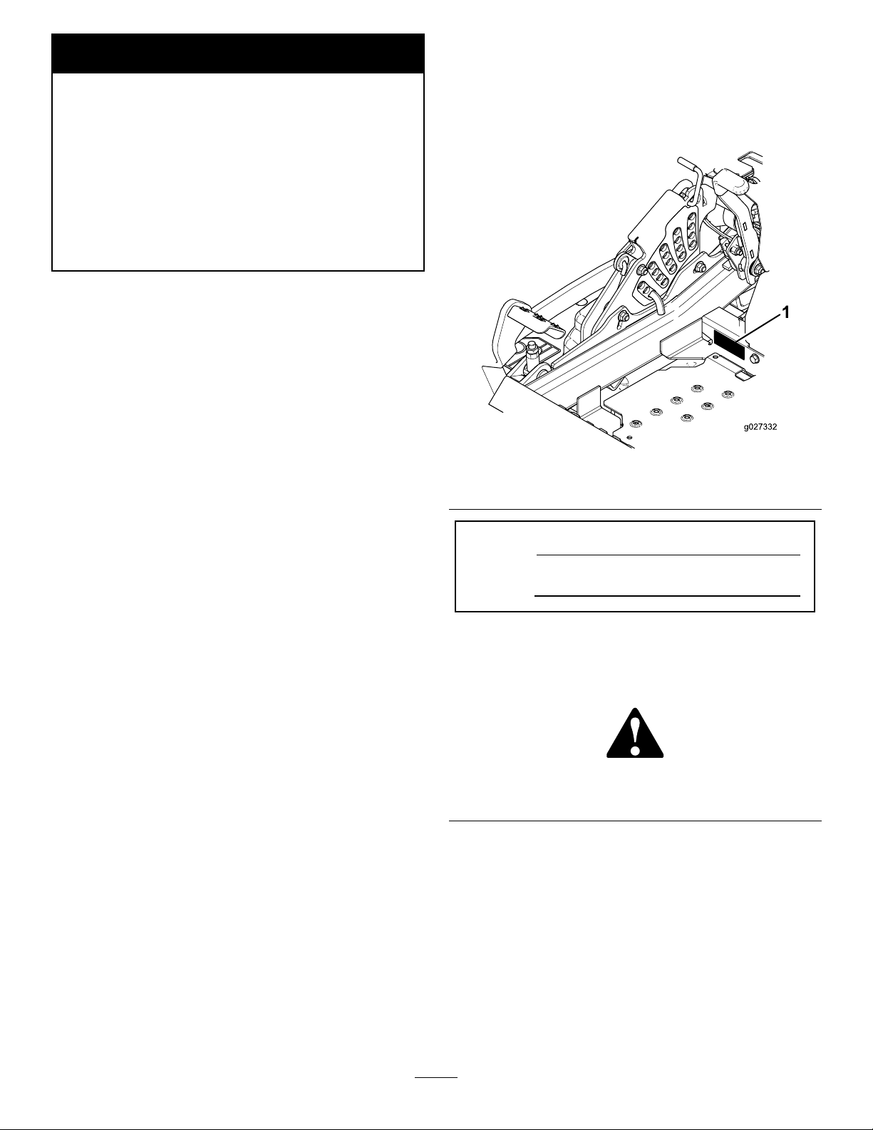
ofyourproductready .Figure1identiesthelocationofthe
modelandserialnumbersontheproduct.Writethenumbers
inthespaceprovided.
Figure1
1.Modelandserialnumberlocation
ModelNo.
SerialNo.
Thismanualidentiespotentialhazardsandhassafety
messagesidentiedbythesafetyalertsymbol(Figure2),
whichsignalsahazardthatmaycauseseriousinjuryordeath
ifyoudonotfollowtherecommendedprecautions.
Introduction
Thisrotary-blade,ridinglawnmowerisintendedtobeused
byresidentialhomeownersorprofessional,hiredoperators.
Itisdesignedprimarilyforcuttinggrassonwell-maintained
lawnsonresidentialorcommercialproperties.Itisnot
designedforcuttingbrushorforagriculturaluses.
Readthisinformationcarefullytolearnhowtooperateand
maintainyourproductproperlyandtoavoidinjuryand
productdamage.Youareresponsibleforoperatingthe
productproperlyandsafely.
YoumaycontactTorodirectlyatwww .Toro.comforproduct
safetyandoperationtrainingmaterials,accessoryinformation,
helpndingadealer,ortoregisteryourproduct.
©2015—TheToro®Company
8111LyndaleAvenueSouth
Bloomington,MN55420
Figure2
1.Safetyalertsymbol
Thismanualuses2wordstohighlightinformation.
Importantcallsattentiontospecialmechanicalinformation
andNoteemphasizesgeneralinformationworthyofspecial
attention.
Contactusatwww.Toro.com.
2
PrintedintheUSA.
AllRightsReserved
Page 3

Contents
Safety...........................................................................4
SafeOperatingPractices...........................................4
SlopeIndicator.......................................................6
SafetyandInstructionalDecals.................................7
ProductOverview.........................................................13
Controls...............................................................13
Specications........................................................14
Operation....................................................................15
AddingFuel...........................................................15
CheckingtheEngine-OilLevel.................................16
BreakinginaNewMachine......................................16
UsingtheRolloverProtectionSystem(ROPS)............16
ThinkSafetyFirst...................................................17
OperatingtheParkingBrake....................................18
OperatingtheMowerBlade-ControlSwitch
(PTO)...............................................................18
OperatingtheThrottle............................................19
OperatingtheIgnitionSwitch..................................19
UsingtheFuelShutoffValve....................................19
StartingandStoppingtheEngine..............................19
TheSafety-InterlockSystem....................................21
DrivingForwardorBackward..................................21
StoppingtheMachine.............................................23
AdjustingtheHeightofCut.....................................23
AdjustingtheAnti-ScalpRollers...............................24
AdjustingtheSkid(s)...............................................24
PositioningtheSeat................................................25
UnlatchingtheSeat.................................................25
ChangingtheSeatSuspension..................................25
UsingtheDrive-WheelReleaseValves.......................25
TransportingtheMachine........................................26
LoadingtheMachine..............................................27
OperatingTips......................................................28
Maintenance.................................................................29
RecommendedMaintenanceSchedule(s)......................29
Lubrication...............................................................30
GreasingandLubrication........................................30
GreasingtheMower...............................................30
LubricatingtheCasterWheelHubs...........................31
EngineMaintenance..................................................32
ServicingtheAirCleaner.........................................32
ServicingtheEngineOil..........................................34
ServicingtheSparkPlug..........................................37
CheckingtheSparkArrester(ifequipped)..................38
FuelSystemMaintenance...........................................39
ServicingtheElectronicFuel-Injection
System..............................................................39
ReplacingtheLow-PressureFuelFilter......................39
ServicingtheHigh-PressureFuelFilter......................39
ServicingtheFuelTank...........................................39
ElectricalSystemMaintenance....................................40
ServicingtheBattery...............................................40
ServicingtheFuses.................................................41
JumpStartingtheMachine.......................................41
DriveSystemMaintenance.........................................43
CheckingtheSeatBelt.............................................43
CheckingtheRolloverProtectionSystem(ROPS)
Knobs...............................................................43
AdjustingtheTracking............................................43
CheckingtheTirePressure......................................44
CheckingtheWheelLugNuts..................................44
CheckingtheWheelHubSlottedNut........................44
AdjustingtheCaster-PivotBearing............................44
UsingtheClutchShim............................................45
CoolingSystemMaintenance......................................47
CleaningtheEngineScreenandEngine-Oil
Cooler...............................................................47
CleaningtheEngineCoolingFinsand
Shrouds.............................................................47
CheckingandCleaningtheHydraulicUnit
Shrouds.............................................................47
BrakeMaintenance....................................................48
AdjustingtheParkingBrake.....................................48
BeltMaintenance......................................................49
InspectingtheBelts................................................49
ReplacingtheCounter-RotatingBelt.........................49
ReplacingtheMowerDeckBelt................................50
ReplacingtheHydraulicPump-DriveBelt..................51
ControlsSystemMaintenance.....................................52
AdjustingtheControlHandlePosition......................52
AdjustingtheMotion-ControlLinkage......................52
AdjustingtheMotion-ControlDamper.....................53
AdjustingtheMotion-ControlNeutral-Lock
Pivot.................................................................53
HydraulicSystemMaintenance....................................54
ServicingtheHydraulicSystem.................................54
MowerDeckMaintenance...........................................56
LevelingtheMowerDeck........................................56
ServicingtheCuttingBlades.....................................58
RemovingtheMowerDeck.....................................61
Cleaning...................................................................63
CleaningundertheMower.......................................63
DisposingofWaste.................................................63
Storage........................................................................63
CleaningandStorage..............................................63
Troubleshooting...........................................................65
Schematics...................................................................68
3
Page 4

Safety
Improperuseormaintenancebytheoperatororownercan
resultininjury.Toreducethepotentialforinjury,complywith
thesesafetyinstructionsandalwayspayattentiontothesafety
alertsymbol,whichmeansCAUTION,WARNING,or
DANGER-“personalsafetyinstruction."Failuretocomply
withtheinstructionmayresultinpersonalinjuryordeath.
Thisproductiscapableofamputatinghandsandfeetand
throwingobjects.Alwaysfollowallsafetyinstructionsto
avoidseriousinjuryordeath.
Thisproductisdesignedforcuttingandrecyclinggrassor,
whenequippedwithagrassbagger,forcatchingcutgrass.
Anyuseforpurposesotherthanthesecouldprovedangerous
touserandbystanders.
SafeOperatingPractices
ThefollowinginstructionsareadaptedfromANSIstandard
B71.4-2012.
Training
•ReadtheOperator'sManualandothertrainingmaterial.If
theoperator(s)ormechanic(s)cannotreadthemanual
language,itistheowner'sresponsibilitytoexplainthis
materialtothem.
•Becomefamiliarwiththesafeoperationoftheequipment,
operatorcontrols,andsafetysigns.
•Alloperatorsandmechanicsshouldbetrained.The
ownerisresponsiblefortrainingtheusers.
•Neverletchildrenoruntrainedpeopleoperateorservice
theequipment.Localregulationsmayrestricttheageof
theoperator.
•Theowner/usercanpreventandisresponsiblefor
accidentsorinjuriesoccurringtopeopleordamageto
property.
Preparation
•Evaluatetheterraintodeterminewhataccessoriesand
attachmentsareneededtoproperlyandsafelyperform
thejob.Onlyuseaccessoriesandattachmentsapproved
bythemanufacturer.
•Wearappropriateclothingincludinghardhat,safety
glassesandhearingprotection.Longhair,looseclothing
orjewelrymaygettangledinmovingparts.
•Inspecttheareawheretheequipmentistobeusedand
removeallobjectssuchasrocks,toysandwirewhichcan
bethrownbythemachine.
•Checkthatoperator'spresencecontrols,safetyswitches
andshieldsareattachedandfunctioningproperly.Donot
operateunlesstheyarefunctioningproperly.
Operation
•Lightningcancausesevereinjuryordeath.Iflightning
isseenorthunderisheardinthearea,donotoperate
themachine;seekshelter.
•Neverrunanengineinanenclosedarea.
•Onlyoperateingoodlight,keepingawayfromholesand
hiddenhazards.
•Besurealldrivesareinneutralandparkingbrakeis
engagedbeforestartingengine.Onlystartenginefrom
theoperator'sposition.
•Besureofyourfootingwhileusingthismachine,
especiallywhenbackingup.Walk,don'trun.Never
operateonwetgrass.Reducedfootingcouldcause
slipping.
•Slowdownanduseextracareonhillsides.Besureto
travelsidetosideonhillsides.Turfconditionscanaffect
themachine'sstability.Usecautionwhileoperatingnear
drop-offs.
•Slowdownandusecautionwhenmakingturnsandwhen
changingdirectionsonslopes.
•Neverraisedeckwiththebladesrunning.
•NeveroperatewiththePTOshield,orotherguardsnot
securelyinplace.Besureallinterlocksareattached,
adjustedproperly ,andfunctioningproperly.
•Neveroperatewiththedischargedeectorraised,
removedoraltered,unlessusingagrasscatcher.
•Donotchangetheenginegovernorsettingoroverspeed
theengine.
•Stoponlevelground,disengagedrives,engageparking
brake(ifprovided),shutoffenginebeforeleavingthe
operator'spositionforanyreasonincludingemptyingthe
catchersoruncloggingthechute.
•Stopequipmentandinspectbladesafterstrikingobjects
orifanabnormalvibrationoccurs.Makenecessary
repairsbeforeresumingoperations.
•Keephandsandfeetawayfromthecuttingunit.
•Lookbehindanddownbeforebackinguptobesureof
aclearpath.
•Keeppetsandbystandersaway .
•Slowdownandusecautionwhenmakingturnsand
crossingroadsandsidewalks.Stopbladesifnotmowing.
•Beawareofthemowerdischargedirectionanddonot
pointitatanyone.
•Donotoperatethemowerundertheinuenceofalcohol
ordrugs.
•Usecarewhenloadingorunloadingthemachineinto
orfromatrailerortruck.
•Usecarewhenapproachingblindcorners,shrubs,trees,
orotherobjectsthatmayobscurevision.
•Lightningcancausesevereinjuryordeath.Iflightning
isseenorthunderisheardinthearea,donotoperate
themachine;seekshelter.
4
Page 5

RolloverProtectionSystem(ROPS)UseandMaintenance
•TheROPSisanintegralandeffectivesafetydevice.Keep
afoldingROPSintheraisedandlockedpositionanduse
theseatbeltwhenoperatingthemachine.
•LowerafoldingROPStemporarilyonlywhenabsolutely
necessary.Donotweartheseatbeltwhenfoldeddown.
•Beawarethereisnorolloverprotectionwhenafolded
ROPSisinthedownposition.
•Becertainthattheseatbeltcanbereleasedquicklyin
theeventofanemergency.
•Iffuelisspilledonclothing,changeclothingimmediately.
•Neveroverllfueltank.Replacefuelcapandtighten
securely.
Maintenanceandstorage
•Disengagedrives,setparkingbrake,stopengineand
removekeyordisconnectsparkplugwire.W aitforall
movementtostopbeforeadjusting,cleaningorrepairing.
•Cleangrassanddebrisfromcuttingunit,drives,mufers,
andenginetohelppreventres.Cleanupoilorfuel
spillage.
•Checktheareatobemowedandneverfolddowna
foldingROPSinareaswherethereareslopes,dropoffs
orwater.
•Checkcarefullyforoverheadclearances(i.e.branches,
doorways,electricalwires)beforedrivingunderany
objectsanddonotcontactthem.
•KeeptheROPSinsafeoperatingconditionby
periodicallythoroughlyinspectingfordamageand
keepingallmountingfastenerstight.
•ReplaceadamagedROPS.Donotrepairorrevise.
•DonotremovetheROPS.
•AnyalterationstoaROPSmustbeapprovedbythe
manufacturer.
Safehandlingoffuels
•Toavoidpersonalinjuryorpropertydamage,use
extremecareinhandlinggasoline.Gasolineisextremely
ammableandthevaporsareexplosive.
•Extinguishallcigarettes,cigars,pipes,andothersources
ofignition.
•Useonlyanapprovedfuelcontainer.
•Letenginecoolbeforestoringanddonotstorenear
ame.
•Shutofffuelwhilestoringortransporting.Donotstore
fuelnearamesordrainindoors.
•Parkmachineonlevelground.Setparkingbrake.Never
allowuntrainedpersonneltoservicemachine.
•Usejackstandstosupportcomponentswhenrequired.
•Carefullyreleasepressurefromcomponentswithstored
energy.
•Disconnectthebatteryorremovesparkplugwirebefore
makinganyrepairs.Disconnectthenegativeterminalrst
andthepositivelast.Reconnectthepositiverstand
negativelast.
•Usecarewhencheckingblades.Wraptheblade(s)orwear
thicklypaddedgloves,andusecautionwhenservicing
them.Onlyreplaceblades.Neverstraightenorweld
them.
•Keephandsandfeetawayfrommovingparts.Ifpossible,
donotmakeadjustmentswiththeenginerunning.
•Keepallpartsingoodworkingconditionandallhardware
tightened.Replaceallwornordamageddecals.
•Neverremovefuelcaporaddfuelwiththeengine
running.
•Allowenginetocoolbeforerefueling.
•Neverrefuelthemachineindoors.
•Neverstorethemachineorfuelcontainerwherethereis
anopename,spark,orpilotlightsuchasonawater
heateroronotherappliances.
•Neverllcontainersinsideavehicleoronatruckor
trailerbedwithaplasticliner.Alwaysplacecontainerson
thegroundawayfromyourvehiclebeforelling.
•Removeequipmentfromthetruckortrailerandrefuelit
ontheground.Ifthisisnotpossible,thenrefuelsuch
equipmentwithaportablecontainer,ratherthanfroma
fueldispensernozzle.
•Keepthenozzleincontactwiththerimofthefueltank
orcontaineropeningatalltimesuntilfuelingiscomplete.
Donotuseanozzlelockopendevice.
Hauling
•Usecarewhenloadingorunloadingthemachineintoa
trailerortruck.
•Usefullwidthrampsforloadingmachineintotraileror
truck.
•Tiethemachinedownsecurelyusingstraps,chains,cable,
orropes.Bothfrontandrearstrapsshouldbedirected
downandoutwardfromthemachine.
5
Page 6
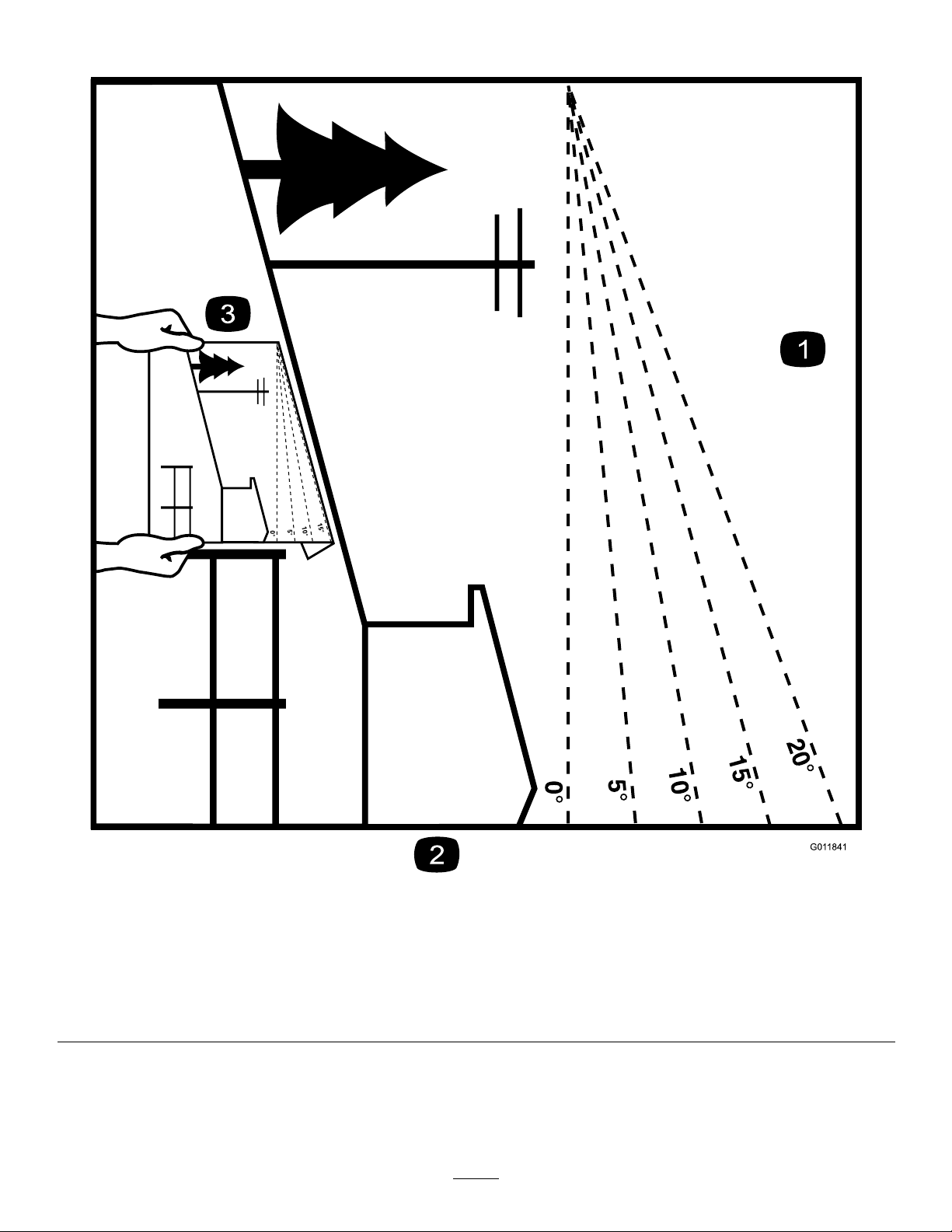
SlopeIndicator
G011841
Figure3
Thispagemaybecopiedforpersonaluse.
1.Themaximumslopeyoucansafelyoperatethemachineonis15degrees.Usetheslopecharttodeterminethedegreeofslope
ofhillsbeforeoperating.Donotoperatethismachineonaslopegreaterthan15degrees.Foldalongtheappropriateline
tomatchtherecommendedslope.
2.Alignthisedgewithaverticalsurface,atree,building,fencepole,etc.
3.Exampleofhowtocompareslopewithfoldededge.
6
Page 7
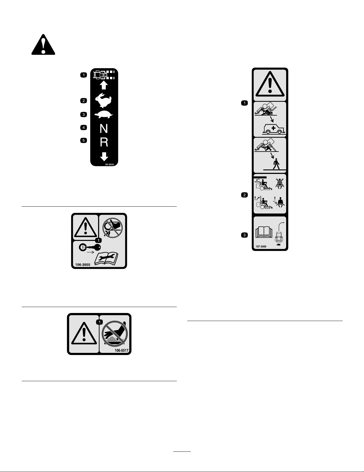
SafetyandInstructionalDecals
Safetydecalsandinstructionsareeasilyvisibletotheoperatorandarelocatednearanyareaofpotential
danger.Replaceanydecalthatisdamagedorlost.
99-8936
1.Machinespeed4.Neutral
2.Fast5.Reverse
3.Slow
106–2655
1.Warning-donottouchorapproachmovingbelts;remove
theignitionkeyandreadtheinstructionsbeforeservicing
orperformingmaintenance.
106-5517
1.Warning–Donottouchthehotsurface.
107-3069
1.Warning–thereisnorolloverprotectionwhentherollbaris
down.
2.Toavoidinjuryordeathfromarolloveraccident,keepthe
rollbarinthefullyraisedandlockedpositionandwear
theseatbelt.Lowertherollbaronlywhenabsolutely
necessary;donotwearthetheseatbeltwhentherollbaris
down.
3.ReadtheOperator'sManual;driveslowlyandcarefully.
7
Page 8
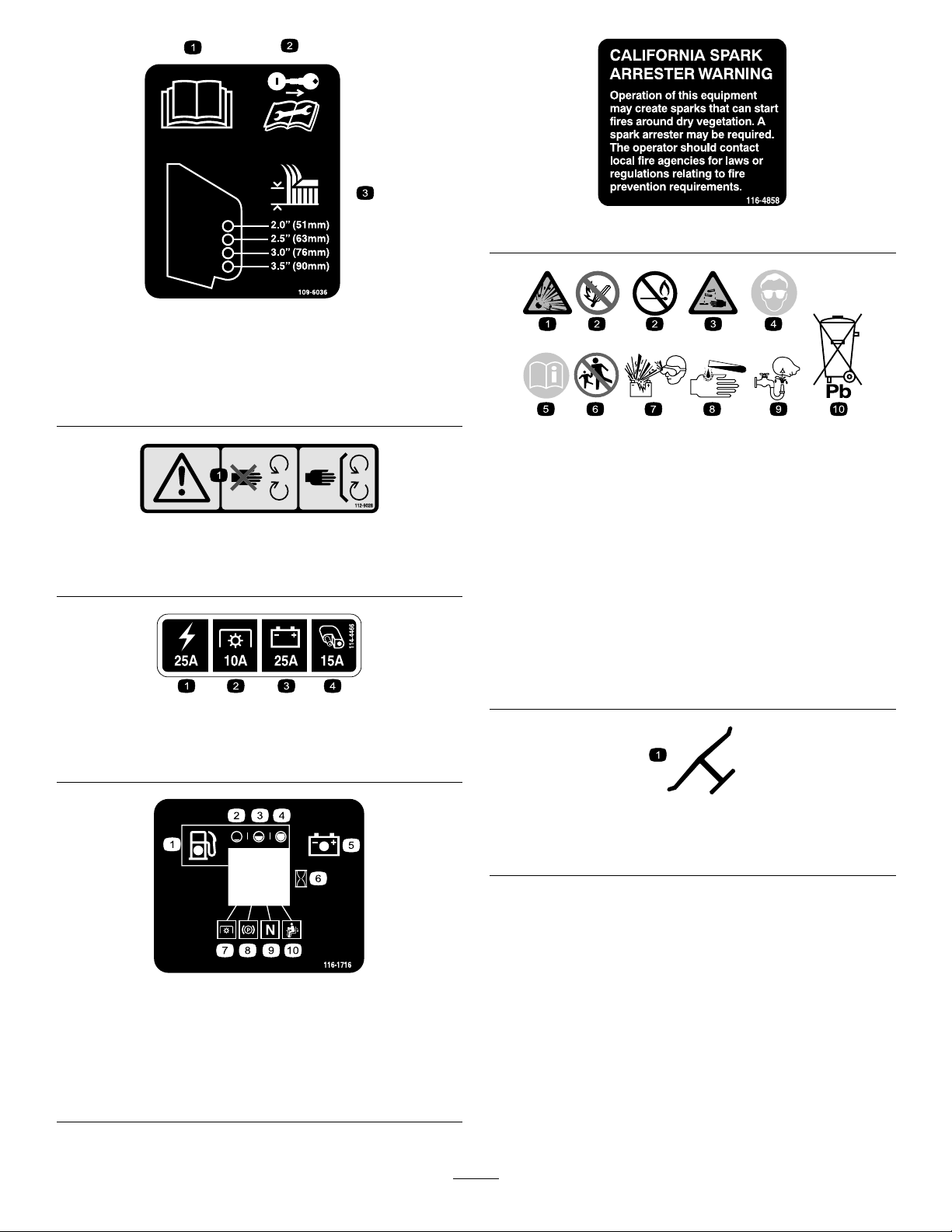
109-6036
1.ReadtheOperator’smanual
2.Removetheignitionkeyandreadtheinstructionsbefore
servicingorperformingmaintenance.
3.Heightofcut
116-4858
BatterySymbols
Someorallofthesesymbolsareonyourbattery
112-9028
1.Warning—stayawayfrommovingparts;keepallguardsin
place.
114-4466
1.Main,25A
2.PTO,10A
3.Charge,25A
4.Auxiliary,15A
1.Explosionhazard
2.Nore,opename,or
smoking.
3.Causticliquid/chemical
burnhazard
4.Weareyeprotection9.Flusheyesimmediately
5.ReadtheOperator's
Manual.
6.Keepbystandersasafe
distancefromthebattery.
7.Weareyeprotection;
explosivegasescan
causeblindnessandother
injuries
8.Batteryacidcancause
blindnessorsevereburns.
withwaterandgetmedical
helpfast.
10.Containslead;donot
discard.
Manufacturer'sMark
1.Indicatesthebladeisidentiedasapartfromtheoriginal
machinemanufacturer.
116-1716
1.Fuel6.Hourmeter
2.Empty
3.Half
4.Full9.Neutral
5.Battery
7.PTO
8.Parkingbrake
10.Operatorpresenceswitch
8
Page 9
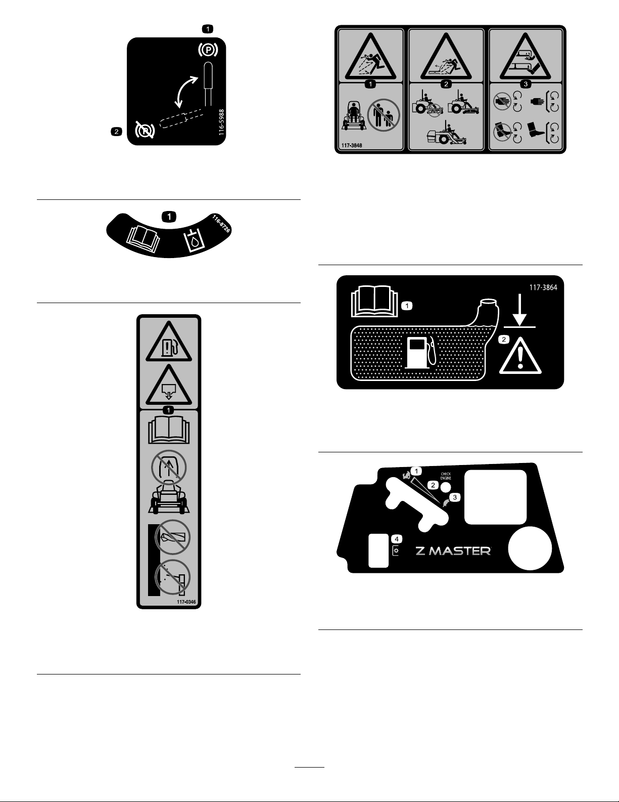
116-5988
1.Parkingbrake—engaged2.Parking
brake—disengaged
116-8726
1.ReadtheOperator’sManualforrecommendedhydrooil.
117-3848
1.Thrownobjecthazard—keepbystandersasafedistance
fromthemachine
2.Thrownobjecthazard,mower-donotoperatewithoutthe
deector,dischargecoverorgrasscollectionsystemin
place.
3.Cutting/dismembermentofhandorfoot—stayawayfrom
movingparts;keepallguardsandshieldsinplace.
117-3864
117-0346
1.Fuelleakhazard—readtheOperator'sManual;donot
attempttoremovetherollbar;donotweld,drillormodify
therollbarinanyway.
1.ReadtheOperator’s
Manual.
1.Fast
2.Variablespeedcontrol
2.Filltobottomofllerneck;
warning—donotoverll
thetank.
121–7586
3.Slow
4.Powertake-off(PTO)
9
Page 10
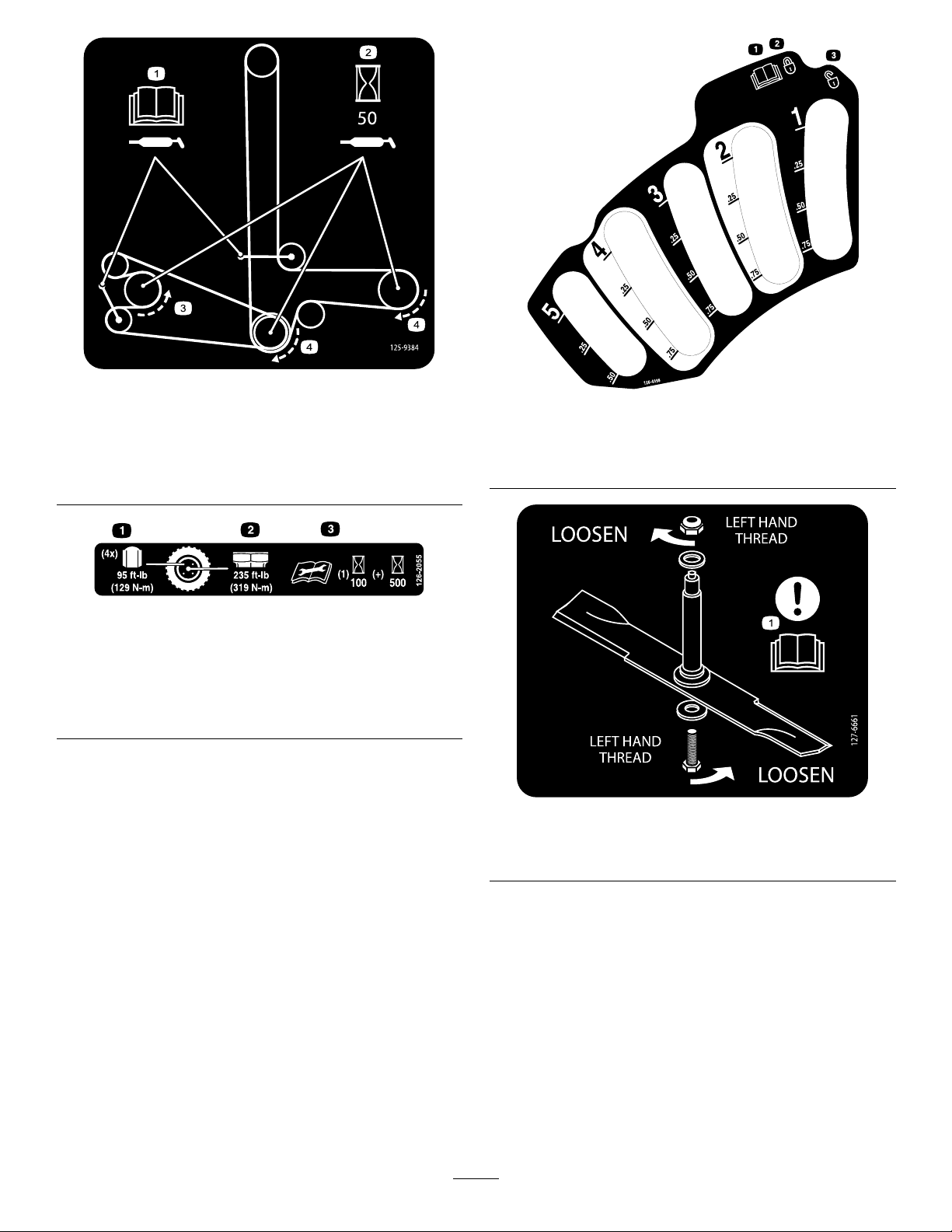
125-9384
1.ReadtheOperator's
Manualforinformationon
lubricatingthebelt.
2.Lubricatethebeltevery50
operatinghours.
3.Counterclockwiserotation
4.Clockwiserotation
126-2055
1.Wheellugnuttorque95ft-lb(129N-m)(4x)
2.Wheelhubnuttorque235ft-lb(319N-m)
3.ReadandunderstandtheOperator’smanualbefore
performinganymaintenance,checktorqueafterrst100
hoursthenevery500hoursthereafter.
1.ReadtheOperator’s
manual
2.Lock
126-4398
3.Unlock
127-6661
1.Attention—readtheOperator'sManualforinformationon
removingtheblade.
10
Page 11
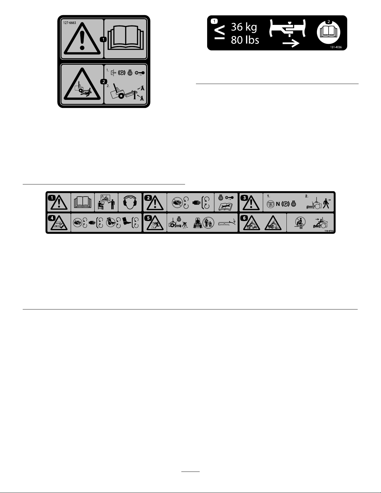
131-4036
1.Warning—readthe
Operator'sManual.
1.Maximumdrawbarpull36
kg(80lb)
2.ReadtheOperator's
Manual.
127-6663
2.Crushinghazard—1)
Engagetheparkingbrake,
stoptheengine,and
removethekeyfrom
theignition;2)Jack
themachineusinga
manufacturer-approved
jack,andalwaysusea
jackstand.
116-8722
1.Warning—ReadtheOperator’sManual.Donotoperatethis
machineunlessyouaretrained.Wearhearingprotection.
2.Warning—Stayawayfrommovingparts;keepallguards
inplace.Stopengineandremovekeybeforeadjusting,
servicing,orcleaning.
3.Warning—DisengagePTO,movedriveleversouttoneutral
lockposition,engageparkingbrake,andstopenginebefore
leavingtheoperator’sposition.
4.Cutting/dismembermentofhandorfoot—stayawayfrom
movingparts;keepallguardsandshieldsinplace.
5.Thrownobjecthazard—Pickupobjectsthatcouldbethrown
bymower.Donotoperatewhenpeopleandpetsareinthe
area.Keepdeectorinplace.
6.Crushing/dismembermenthazardofbystanders—donotcarry
passengers,lookforwardanddownwhenoperatingthe
machine,lookbehindanddownwhenreversing.
11
Page 12
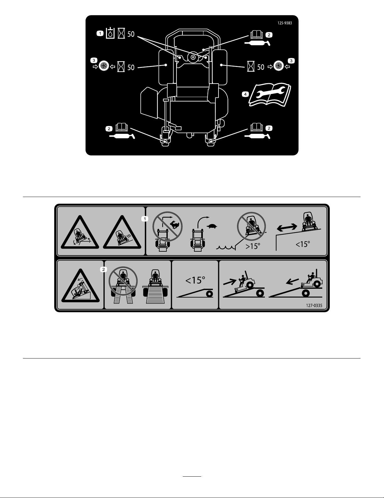
125–9383
1.Checkhydraulicoilevery50operatinghours.3.Checkthetirepressureevery50operatinghours.
2.ReadtheOperator’sManualforinformationonlubricating
themachine.
4.ReadtheOperator’sManualbeforeservicingorperforming
maintenance.
127–0335
1.Tippinghazardonslopes—donotmakesudden,tightturns;
makeslow,wideturns;donotuseonslopesnearopenwater;
donotusethismachineonslopesgreaterthan15degrees.
2.Ramphazard—whenloadingontoatrailer ,donotusedual
ramps;onlyuseasingularrampwideenoughforthemachine
andthathasaninclinelessthan15degrees;backupthe
ramp(inreverse)anddriveforwardofftheramp.
12
Page 13
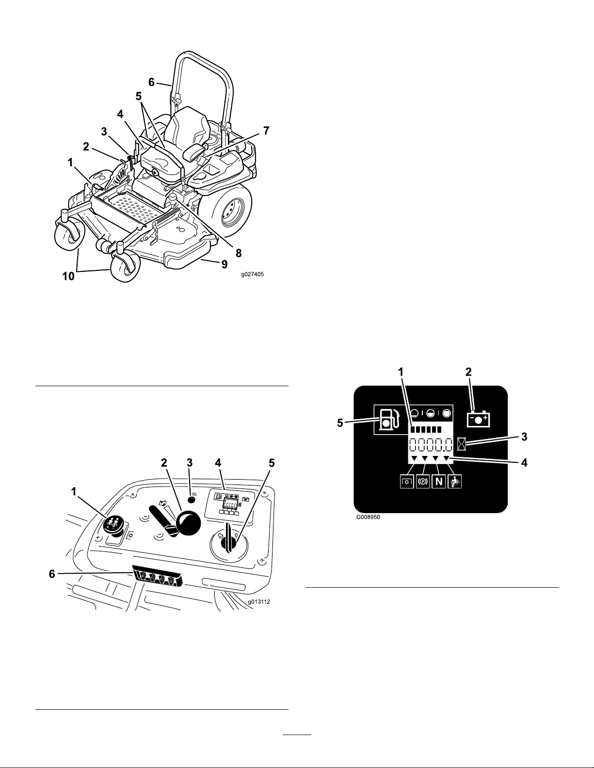
ProductOverview
g027405
g0131 12
1
2
3
4
5
6
25
25
10
15
C
H
ECK
ENG
IN
E
HourMeter
Thehourmeterrecordsthenumberofhourstheenginehas
operated.Itoperateswhentheengineisrunning.Usethese
timesforschedulingregularmaintenance(Figure6).
FuelGauge
Thefuelgaugeislocatedwiththehourmeterandthebars
lightupwhentheignitionswitchison(Figure6).
Theindicatorlightappearswhenthefuellevelislow
(approximatelyonegallonremaininginthefueltank).
Safety-InterlockIndicators
Therearesymbolsonthehourmeterandtheindicatewitha
blacktrianglethattheinterlockcomponentisinthecorrect
position(Figure6).
BatteryIndicatorLight
Figure4
1.Height-of-cutdecklift
pedal
2.Transportlock
3.Parkingbrakelever8.Fuelcap
4.Controls
5.Motion-controllevers
6.Rollbar
7.Seatbelt
9.Mowerdeck
10.Casterwheel
Controls
Becomefamiliarwithallthecontrolsbeforeyoustartthe
engineandoperatethemachine(Figure4andFigure5).
IftheignitionkeyisturnedtotheOnpositionforafew
seconds,thebatteryvoltagewillbedisplayedinthearea
wherethehoursarenormallydisplayed.
Thebatterylightturnsonwhentheignitionisturnedonand
whenthechargeisbelowthecorrectoperatinglevel(Figure
6).
Figure6
1.Fuelgauge(bars)4.Safety-interlocksymbols
2.Batterylight
3.Hourmeter
5.Lowfuelindicatorlight
1.PTOSwitch
2.Throttlecontrol5.Ignitionswitch
3.Malfunctionindicatorlight
(MIL)
Figure5
4.Hour
meter/Safety-interlock
display/Fuelgauge
6.Fuses
ThrottleControl
ThethrottlecontrolisvariablebetweenFastandSlow.
Blade-ControlSwitch(PTO)
Theblade-controlswitch(PTO)isusedtoengagetheelectric
clutchanddrivethemowerblades.Pulltheswitchupto
engagethebladesandrelease.Todisengagetheblades,
13
Page 14

pushtheblade-controlswitch(PTO)downormovea
motion-controlleverintotheneutral-lockposition.
IgnitionSwitch
Thisswitchisusedtostartthemowerengineandhasthree
positions:Start,RunandOff.
Motion-ControlLevers
Themotion-controlleversareusedtodrivethemachine
forward,reverse,andturneitherdirection.
Neutral-LockPosition
Theneutral-lockpositionisusedwiththesafety-interlock
systemtoengageandtodetermineneutralposition.
FuelShutoffValve
Closethefuelshutoffvalve(undertheseat)whentransporting
orstoringthemower.
ElectronicControlUnitMalfunction
IndicatorLight
Length:
60inchMower
Deck
RollBar-Up
RollBar-Down
221.6cm(87.25
inches)
226.0cm(88.95
inches)
Height:
RollBar-UpRollBar-Down
179.1cm(70.5inches)118.9cm(46.8inches)
Weight:
ModelWeight
60inchMowerDecks
72inchMowerDecks
577kg(1271lb)
606kg(1335lb)
72inchMower
Deck
221.6cm(87.25
inches)
226.0cm(88.95
inches)
Theelectroniccontrolunit(ECU)continuouslymonitorsthe
operationoftheEFIsystem.
Ifaproblemorfaultwithinthesystemisdetected,the
malfunctionindicatorlight(MIL)isilluminated.
TheMIListheredlightlocatedintherightconsolepanel.
OncetheMILilluminates,performinitialtroubleshooting
checks.RefertotheMILsectionunderTroubleshooting
(page65).
Ifthesechecksdonotcorrecttheproblem,furtherdiagnosis
andservicingbyanAuthorizedServiceDealerisnecessary.
Attachments/Accessories
AselectionofToroapprovedattachmentsandaccessoriesis
availableforusewiththemachinetoenhanceandexpand
itscapabilities.ContactyourAuthorizedServiceDealeror
Distributororgotowww .Toro.comforalistofallapproved
attachmentsandaccessories.
Specications
Note:Specicationsanddesignaresubjecttochange
withoutnotice.
Width:
WithoutMower
Deck
WithMowerDeck
60inchMower
Deck
134.6cm(53.0
inches)
168.4cm(66.3
inches)
72inchMower
Deck
150.1cm(59.1
inches)
199.0cm(78.3
inches)
14
Page 15

Operation
Note:Determinetheleftandrightsidesofthemachine
fromthenormaloperatingposition.
AddingFuel
•Forbestresults,useonlyclean,fresh(lessthan30days
old),unleadedgasolinewithanoctaneratingof87or
higher((R+M)/2ratingmethod).
•Ethanol:Gasolinewithupto10%ethanol(gasohol)
or15%MTBE(methyltertiarybutylether)byvolume
isacceptable.EthanolandMTBEarenotthesame.
Gasolinewith15%ethanol(E15)byvolumeisnot
approvedforuse.Neverusegasolinethatcontains
morethan10%ethanolbyvolume,suchasE15
(contains15%ethanol),E20(contains20%ethanol),or
E85(containsupto85%ethanol).Usingunapproved
gasolinemaycauseperformanceproblemsand/orengine
damagewhichmaynotbecoveredunderwarranty.
•Donotusegasolinecontainingmethanol.
•Donotstorefueleitherinthefueltankorfuelcontainers
overthewinterunlessafuelstabilizerisused.
•Donotaddoiltogasoline.
DANGER
Incertainconditionsduringfueling,static
electricitycanbereleasedcausingasparkwhich
canignitethegasolinevapors.Areorexplosion
fromgasolinecanburnyouandothersandcan
damageproperty.
•Alwaysplacegasolinecontainersontheground
awayfromyourvehiclebeforelling.
•Donotllgasolinecontainersinsideavehicleor
onatruckortrailerbedbecauseinteriorcarpets
orplastictruckbedlinersmayinsulatethe
containerandslowthelossofanystaticcharge.
•Whenpractical,removegas-poweredequipment
fromthetruckortrailerandrefueltheequipment
withitswheelsontheground.
•Ifthisisnotpossible,thenrefuelsuch
equipmentonatruckortrailerfromaportable
container,ratherthanfromagasolinedispenser
nozzle.
•Ifagasolinedispensernozzlemustbeused,
keepthenozzleincontactwiththerimofthe
fueltankorcontaineropeningatalltimesuntil
fuelingiscomplete.
DANGER
Incertainconditions,gasolineisextremely
ammableandhighlyexplosive.Areorexplosion
fromgasolinecanburnyouandothersandcan
damageproperty.
•Fillthefueltankoutdoors,inanopenarea,
whentheengineiscold.Wipeupanygasoline
thatspills.
•Neverllthefueltankinsideanenclosedtrailer.
•Donotllthefueltankcompletelyfull.Add
gasolinetothefueltankuntilthelevelis6to13
mm(1/4to1/2inch)belowthebottomofthe
llerneck.Thisemptyspaceinthetankallows
gasolinetoexpand.
•Neversmokewhenhandlinggasoline,andstay
awayfromanopenameorwheregasoline
fumesmaybeignitedbyaspark.
•Storegasolineinanapprovedcontainerand
keepitoutofthereachofchildren.Neverbuy
morethana30-daysupplyofgasoline.
•Donotoperatewithoutentireexhaustsystemin
placeandinproperworkingcondition.
WARNING
Gasolineisharmfulorfatalifswallowed.Long-term
exposuretovaporscancauseseriousinjuryand
illness.
•Avoidprolongedbreathingofvapors.
•Keepfaceawayfromnozzleandgastankor
conditionerbottleopening.
•Avoidcontactwithskin;washoffspillagewith
soapandwater.
UsingStabilizer/Conditioner
Useafuelstabilizer/conditionerinthemachinetoprovide
thefollowingbenets:
•Keepsgasolinefreshduringstorageof90daysorless.
Forlongerstorageitisrecommendedthatthefueltank
bedrained.
•Cleanstheenginewhileitruns
•Eliminatesgum-likevarnishbuildupinthefuelsystem,
whichcauseshardstarting
Important:Donotusefueladditivescontaining
methanolorethanol.
Addthecorrectamountofgasstabilizer/conditionerto
thegas.
Note:Afuelstabilizer/conditionerismosteffective
whenmixedwithfreshgasoline.T ominimizethechance
15
Page 16
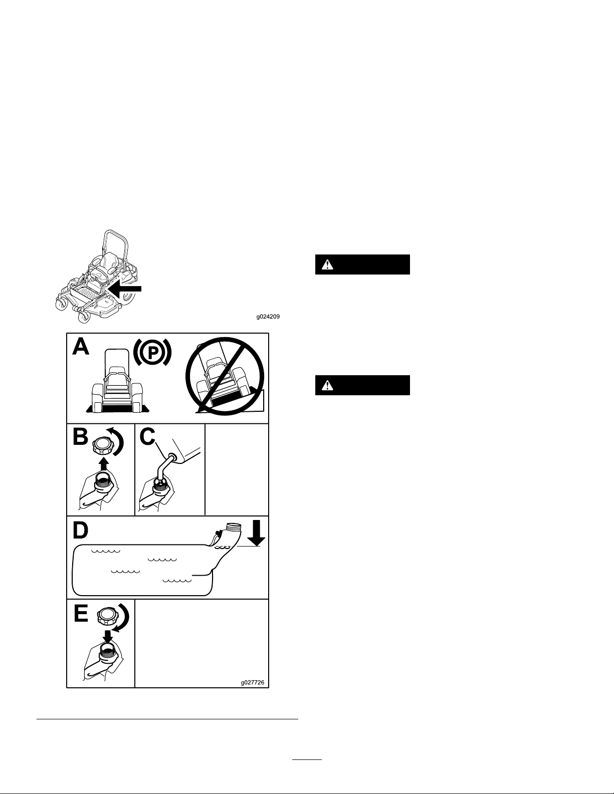
ofvarnishdepositsinthefuelsystem,usefuelstabilizer
g024209
atalltimes.
FillingtheFuelTank
Note:Donotllthefueltankcompletelyfull.Fillthefuel
tanktothebottomofthellerneck.Theemptyspaceinthe
tankallowsthegasolinetoexpand.
1.Parkthemachineonlevelground.
2.Shuttheengineoffandsettheparkingbrake.
3.Cleanaroundthefueltankcap.
4.Fillthefueltanktothebottomofthellerneck.
Ensurethereisemptyspaceinthetanktoallowthe
gasolinetoexpand(Figure7).
CheckingtheEngine-OilLevel
Beforeyoustarttheengineandusethemachine,check
theoillevelintheenginecrankcase;refertoCheckingthe
Engine-OilLevel(page34).
BreakinginaNewMachine
Newenginestaketimetodevelopfullpower.Mowerdecks
anddrivesystemshavehigherfrictionwhennew,placing
additionalloadontheengine.Allow40to50hoursof
break-intimefornewmachinestodevelopfullpowerand
bestperformance.
UsingtheRolloverProtection System(ROPS)
WARNING
Toavoidinjuryordeathfromrollover:keeptheroll
barinthefullyraisedlockedpositionandusethe
seatbelt.
Ensurethattherearpartoftheseatissecuredwith
theseatlatch.
WARNING
Thereisnorolloverprotectionwhentherollbaris
inthedownposition.
•Lowertherollbaronlywhenabsolutely
necessary.
•Donotweartheseatbeltwhentherollbaris
inthedownposition.
•Driveslowlyandcarefully.
•Raisetherollbarassoonasclearancepermits.
•Checkcarefullyforoverheadclearances(i.e.
branches,doorways,electricalwires)before
drivingunderanyobjectsanddonotcontact
them.
Important:Lowertherollbaronlywhenabsolutely
necessary.
Figure7
Important:Ensurethattherearpartoftheseatis
securedwiththeseatlatch.
1.Tolowertherollbar,applyforwardpressuretothe
upperpartoftherollbar.
2.Pullbothknobsoutandrotatethem90°sotheyare
notengaged(Figure8).
16
Page 17
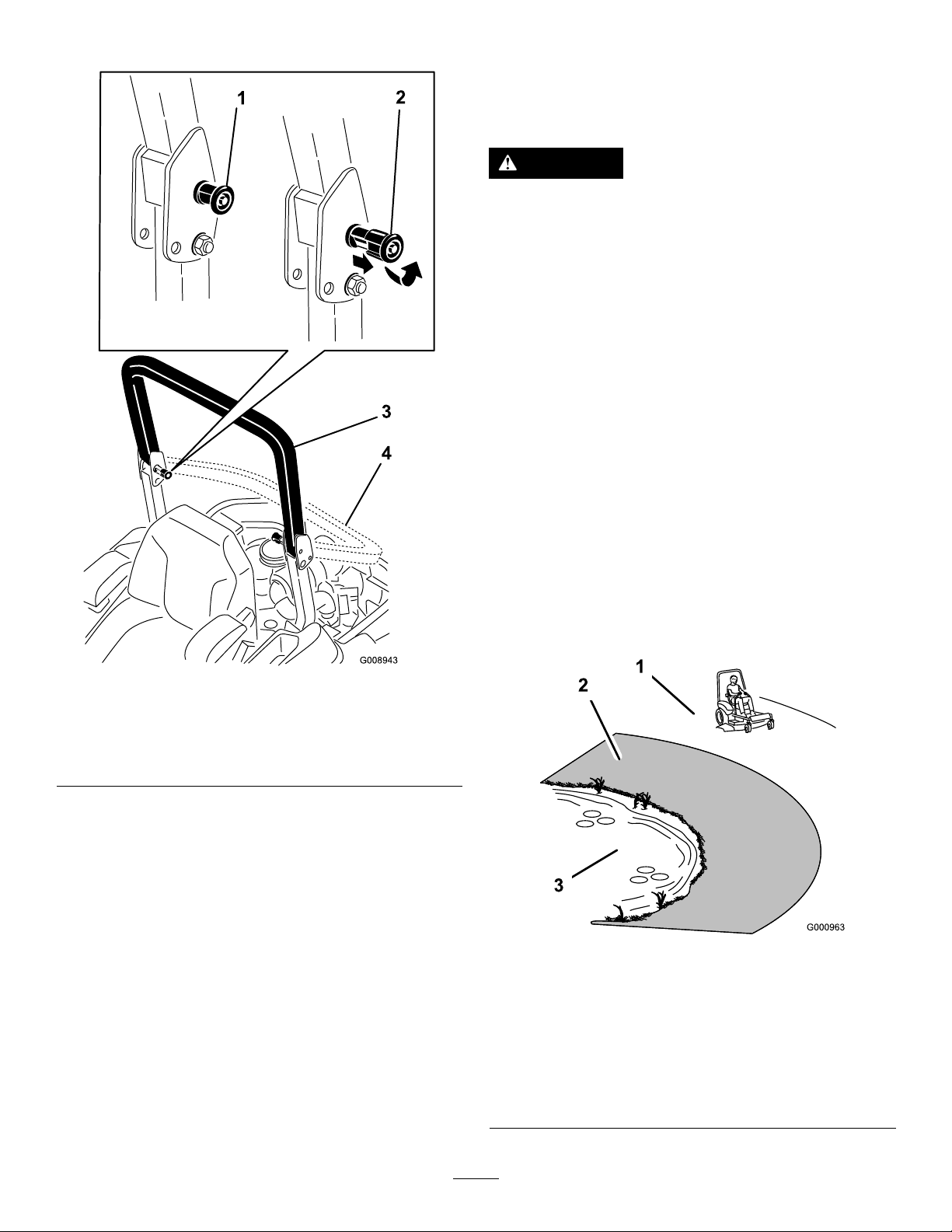
3.Lowertherollbartothedownposition(Figure8).
ThinkSafetyFirst
Pleasereadallsafetyinstructionsandsymbolsinthesafety
section.Knowingthisinformationcouldhelpyouor
bystandersavoidinjury.
DANGER
Operatingonwetgrassorsteepslopescancause
slidingandlossofcontrol.
Wheelsdroppingoveredgescancauserollovers,
whichmayresultinseriousinjury,deathor
drowning.
Thereisnorolloverprotectionwhentherollbaris
down.
Alwayskeeptherollbarinthefullyraisedand
lockedpositionandusetheseatbelt.
Readandfollowtherolloverprotectioninstructions
andwarnings.
Toavoidlossofcontrolandpossibilityofrollover:
Figure8
1.ROPSknob
2.PullROPSknoboutand
rotate90degrees
3.Rollbarintheupright
position
4.Rollbarinthefolded
position
4.Toraisetherollbar,raisetherollbartotheoperate
position,rotatetheknobssotheymovepartiallyinto
thegrooves(Figure8).
5.Raisetherollbartothefulluprightpositionwhile
pushingontheupperrollbarandthepinswillsnap
intopositionwhentheholesalignwiththepins(Figure
8).Pushontherollbarandensurethatbothpinsare
engaged.
Important:Alwaysusetheseatbeltwiththeroll
barinthefullyraisedposition.
•Donotoperateneardrop-offsornearwater.
•Donotoperateonslopesgreaterthan15degrees.
•Reducespeedanduseextremecautionon
slopes.
•Avoidsuddenturnsorrapidspeedchanges.
Figure9
1.SafeZone-usethe
ZMasterhereonslopes
lessthan15degreesor
atareas.
2.DangerZone-useawalk
behindmowerand/ora
handtrimmeronslopes
greaterthan15degrees,
neardrop-offsandwater.
3.Water
17
Page 18
CAUTION
G009027
1
2
g027334
g027335
G008945
G009174
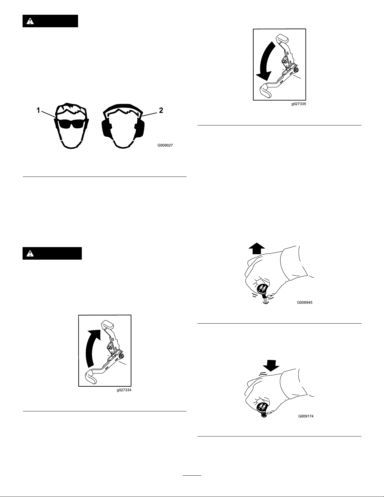
Thismachineproducessoundlevelsinexcessof
85dBAattheoperatorsearandcancausehearing
lossthroughextendedperiodsofexposure.
Wearhearingprotectionwhenoperatingthis
machine.
Theuseofprotectiveequipmentforeyes,ears,feetandhead
isrecommended.
Figure10
1.Wearsafetyglasses
2.Wearhearingprotection
ReleasingtheParkingBrake
Figure12
OperatingtheMower Blade-ControlSwitch(PTO)
Theblade-controlswitch(PTO)startsandstopsthemower
bladesandanypoweredattachments.
OperatingtheParkingBrake
Alwayssettheparkingbrakewhenyoustopthemachineor
leaveitunattended.
SettingtheParkingBrake
WARNING
Parkingbrakemaynotholdmachineparkedona
slopeandcouldcausepersonalinjuryorproperty
damage.
Donotparkonslopesunlesswheelsarechocked
orblocked
EngagingtheBlade-ControlSwitch
(PTO)
Note:Engagingtheblade-controlswitch(PTO)withthe
throttlepositionathalforlesswillcauseexcessivewearto
thedrivebelts.
Figure13
DisengagingtheBlade-ControlSwitch
(PTO)
Figure11
Figure14
18
Page 19
OperatingtheThrottle
G008946
START
RUN
STOP
G008947
G008948
1
2
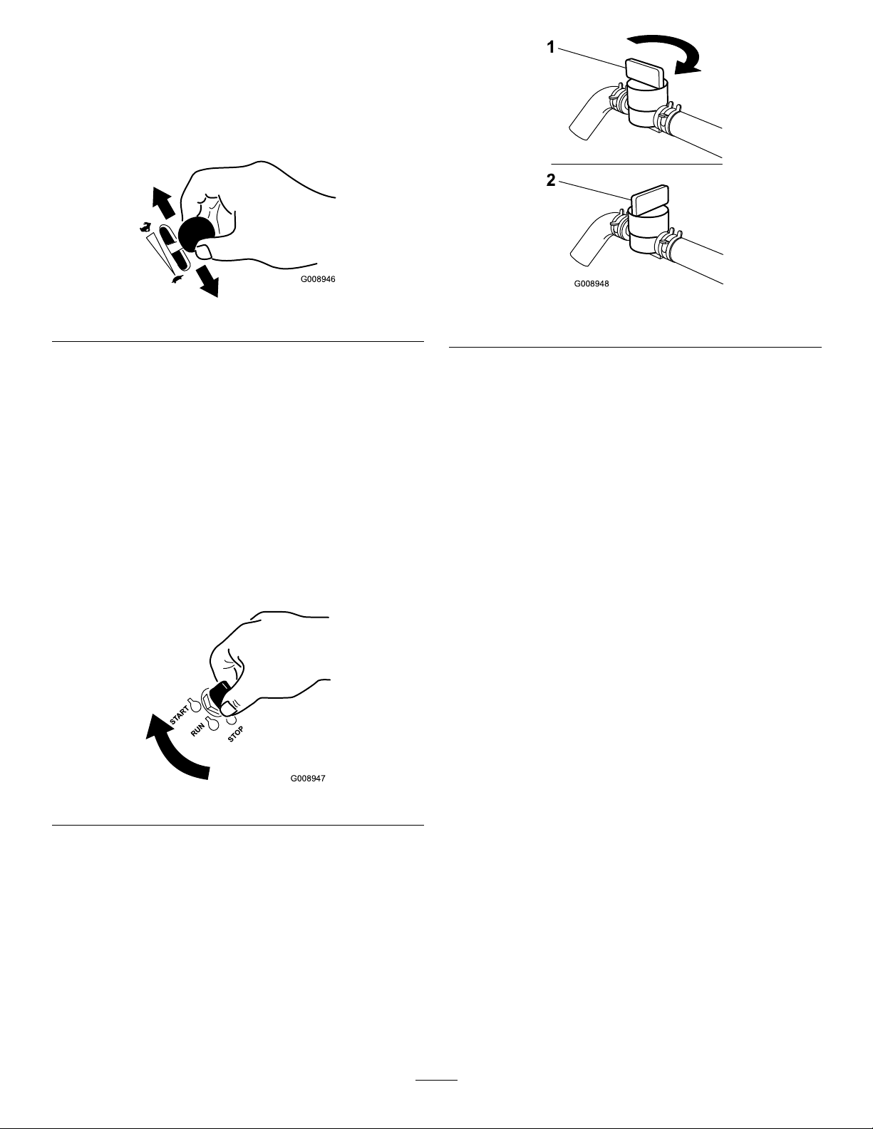
ThethrottlecontrolcanbemovedbetweenFastandSlow
positions(Figure15).
Alwaysusethefastpositionwhenturningonthemowerdeck
withtheblade-controlswitch(PTO).
Figure15
OperatingtheIgnitionSwitch
1.TurntheignitionkeytotheStartposition(Figure16).
Whentheenginesstarts,releasethekey .
Important:Donotengagestarterformorethan5
secondsatatime.Iftheenginefailstostartallow
a15secondcool-downperiodbetweenattempts.
Failuretofollowtheseinstructionscanburnout
thestartermotor.
Note:Additionalstartingcyclesmayberequired
whenstartingtheengineforthersttimeafterthefuel
systemhasbeenwithoutfuelcompletely.
Figure17
1.On2.Off
StartingandStoppingthe Engine
StartingtheEngine
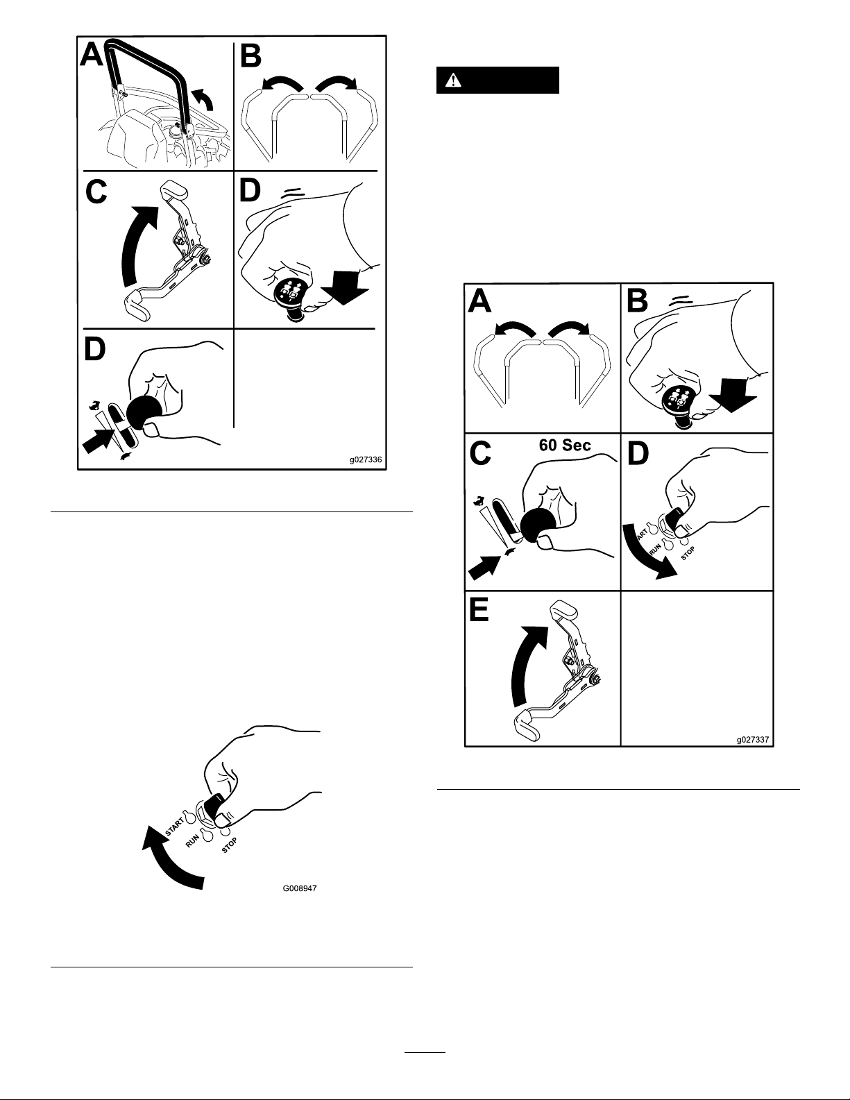
1.RaisetheROPSupandlockintoplace,sitontheseat
andfastentheseatbelt.
2.Movethemotioncontrolstoneutral-lockedposition.
3.Settheparkingbrake;refertoSettingtheParking
Brake(page18).
4.Movetheblade-controlswitch(PTO)totheOff
position(Figure18).
5.MovethethrottlelevermidwaybetweentheSlowand
Fastpositions.
Figure16
2.Turntheignitionkeytostoptostoptheengine.
UsingtheFuelShutoffValve
Thefuelshutoffvalveislocatedundertheseat.Movethe
seatforwardtoaccessit.
Closethefuelshutoffvalvefortransport,maintenance,and
storage.
Ensurethefuelshutoffvalveisopenwhenstartingtheengine.
19
Page 20
A
B
C
D
D
g027336
START
RUN
STOP
G008947
StoppingtheEngine
g027337
A B
C D
E
CAUTION
Childrenorbystandersmaybeinjuredifthey
moveorattempttooperatethemachinewhileitis
unattended.
Alwaysremovetheignitionkeyandsettheparking
brakewhenleavingthemachineunattended,even
ifjustforafewminutes.
Lettheengineidleatslowthrottle(turtle)for60seconds
beforeturningtheignitionswitchoff.
6.TurntheignitionkeytotheStartposition(Figure16).
Whentheenginesstarts,releasethekey .
Important:Donotengagestarterformorethan5
secondsatatime.Iftheenginefailstostartallow
a15secondcool-downperiodbetweenattempts.
Failuretofollowtheseinstructionscanburnout
thestartermotor.
Note:Additionalstartingcyclesmayberequired
whenstartingtheengineforthersttimeafterthefuel
systemhasbeenwithoutfuelcompletely.
Figure18
Figure20
Important:Makesurethatthefuelshutoffvalveis
closedbeforetransportingorstoringthemachine,as
fuelleakagemayoccur.Settheparkingbrakebefore
transporting.Makesuretoremovethekeyasthefuel
pumpmayrunandcausethebatterytolosecharge.
Figure19
1.Off3.Start
2.Run
20
Page 21
TheSafety-InterlockSystem
G009181
1
CAUTION
Ifsafety-interlockswitchesaredisconnectedor
damagedthemachinecouldoperateunexpectedly
causingpersonalinjury.
•Donottamperwiththeinterlockswitches.
•Checktheoperationoftheinterlockswitches
dailyandreplaceanydamagedswitchesbefore
operatingthemachine.
UnderstandingtheSafety-Interlock
System
Thesafety-interlocksystemisdesignedtopreventtheengine
fromstartingunless:
•Theparkingbrakeisengaged.
•Theblade-controlswitch(PTO)isdisengaged.
•Themotion-controlleversareintheneutral-locked
position
Thesafety-interlocksystemalsoisdesignedtostopthe
enginewhenthetractioncontrolsaremovedfromthelocked
positionwiththeparkingbrakeengagedorifyourisefrom
theseatwhenthePTOisengaged.
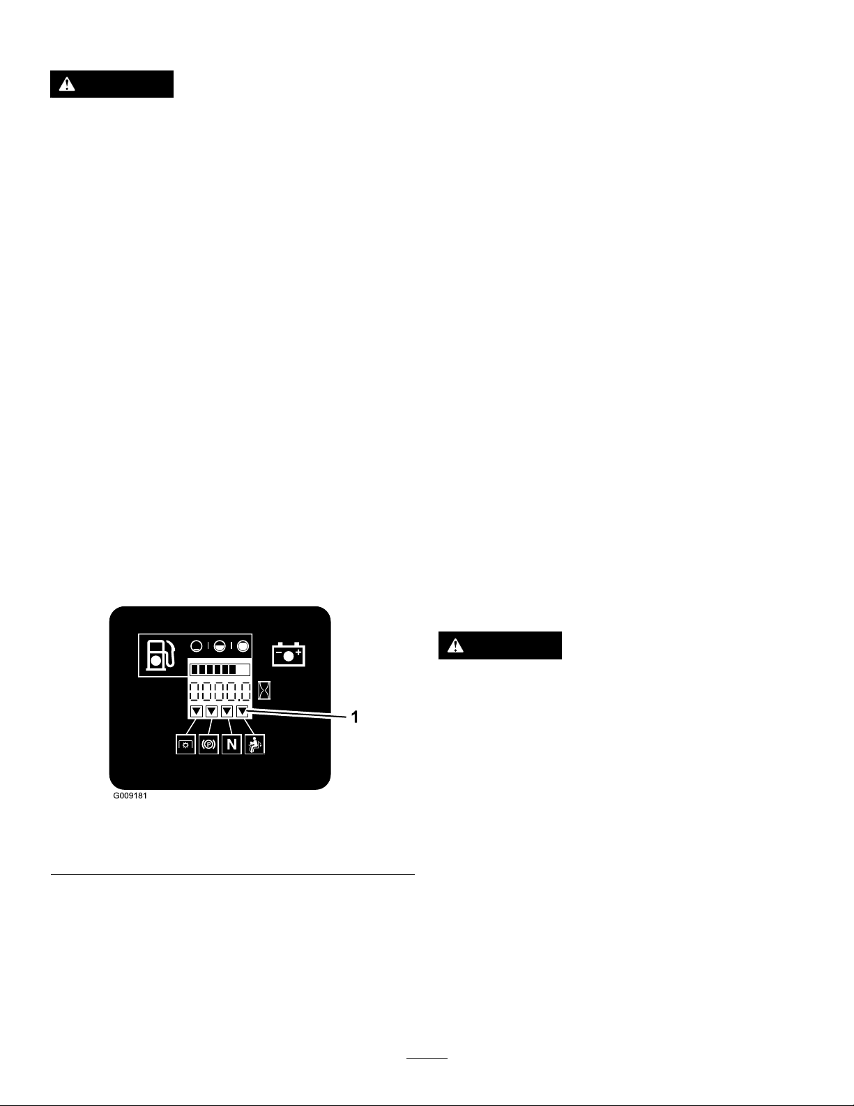
Thehourmeterhassymbolstonotifytheuserwhenthe
interlockcomponentisinthecorrectposition.Whenthe
componentisinthecorrectposition,atrianglewilllightup
inthecorrespondingsquare.
1.Sittingontheseat,engagetheparkingbrakeandmove
theblade-controlswitch(PTO)toon.Trystartingthe
engine;theengineshouldnotcrank.
2.Sittingontheseat,engagetheparkingbrakeandmove
theblade-controlswitch(PTO)tooff.Moveeither
motion-controllever(outofneutral-lockedposition).
Trystartingtheengine;theengineshouldnotcrank.
Repeatforothercontrollever.
3.Sittingontheseat,engagetheparkingbrake,move
theblade-controlswitch(PTO)tooffandmovethe
motion-controlleverstoneutral-lockposition.Now
starttheengine.Whiletheengineisrunning,releasethe
parkingbrake,engagetheblade-controlswitch(PTO)
andriseslightlyfromtheseat;theengineshouldstop.
4.Sittingontheseat,engagetheparkingbrake,move
theblade-controlswitch(PTO)tooffandmovethe
motion-controlleverstoneutral-lockposition.Now
starttheengine.Whiletheengineisrunning,center
eithermotion-controlandmove(forwardorreverse);
theengineshouldstop.Repeatforothermotion
control.
5.Sittingontheseat,disengagetheparkingbrake,move
theblade-controlswitch(PTO)tooffandmovethe
motion-controlleverstoneutral-lockposition.Try
startingtheengine;theengineshouldnotcrank.
DrivingForwardorBackward
Thethrottlecontrolregulatestheenginespeedasmeasured
inrpm(revolutionsperminute).Placethethrottlecontrolin
thefastpositionforbestperformance.Alwaysoperateinthe
fullthrottlepositionwhenmowing.
Figure21
1.Triangleslightupwhentheinterlockcomponentsareinthe
correctposition
TestingtheSafety-InterlockSystem
ServiceInterval:Beforeeachuseordaily
Testthesafety-interlocksystembeforeyouusethemachine
eachtime.Ifthesafetysystemdoesnotoperateasdescribed
below,haveanAuthorizedServiceDealerrepairthesafety
systemimmediately.
CAUTION
Machinecanspinveryrapidly.Operatormaylose
controlofmachineandcausepersonalinjuryor
damagetomachine.
•Usecautionwhenmakingturns.
•Slowthemachinedownbeforemakingsharp
turns.
21
Page 22

UsingtheMotion-ControlLevers
G008952
G008953
Figure23
Figure22
1.Motion-control
lever—neutral-lock
position
2.Center,unlockedposition5.Frontofmachine
3.Forward
4.Backward
DrivingForward
Note:Theenginewillkillifthetractioncontrolleversare
movedwiththeparkingbrakeengaged.
Tostop,pullthemotion-controlleverstotheneutralposition.
1.Releasetheparkingbrake;refertoReleasingthe
ParkingBrake(page18).
2.Movetheleverstothecenter,unlockedposition.
3.Togoforward,slowlypushthemotion-controllevers
forward(Figure23).
DrivingBackward
1.Movetheleverstothecenter,unlockedposition.
2.Togobackward,lookbehindandslowlypullthe
motion-controlleversrearward(Figure24).
Figure24
22
Page 23
StoppingtheMachine
Tostopthemachine,movethetractioncontrolleversto
neutralandmovetolockedposition,disengagethepower
takeoff(blade-controlswitch(PTO),andturntheignition
keytooff.
Settheparkingbrakewhenyouleavethemachine;referto
SettingtheParkingBrake(page18).Remembertoremove
thekeyfromtheignitionswitch.
CAUTION
Childrenorbystandersmaybeinjuredifthey
moveorattempttooperatethemachinewhileitis
unattended.
Alwaysremovetheignitionkeyandsettheparking
brakewhenleavingthemachineunattended,even
ifjustforafewminutes.
AdjustingtheHeightofCut
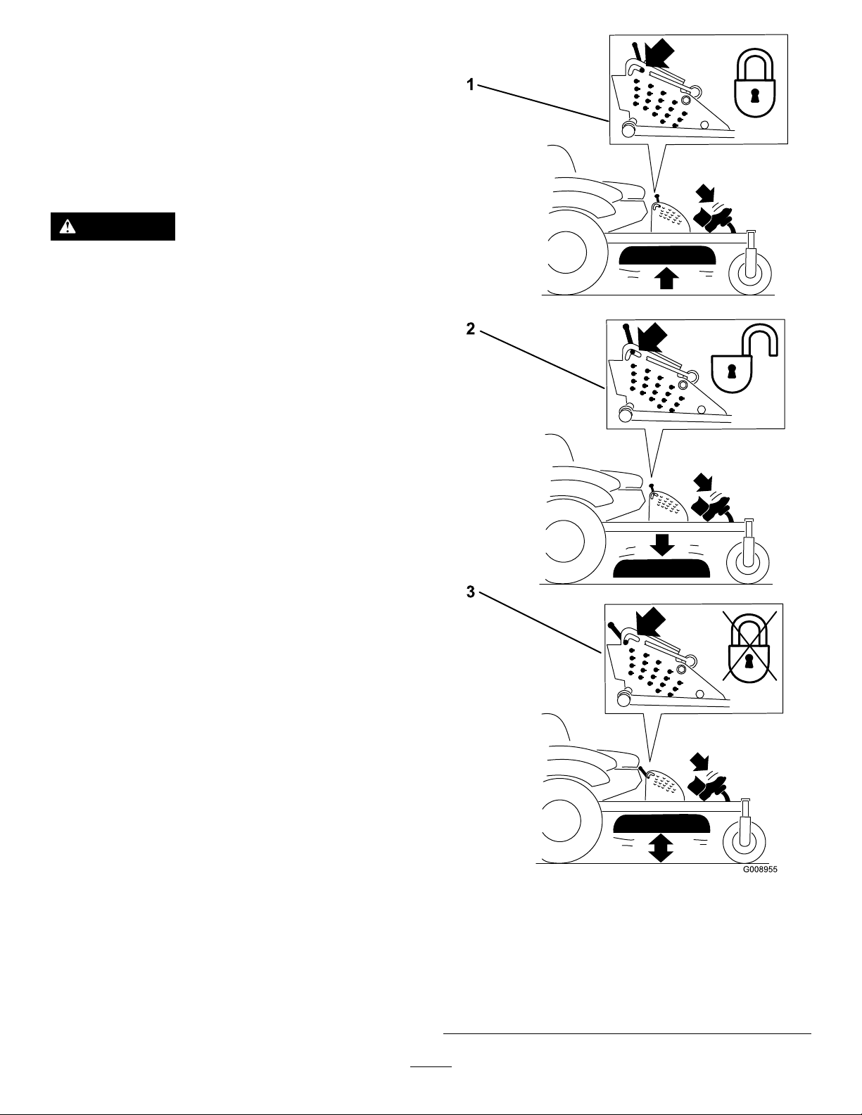
UsingtheTransportLock
Thetransportlockhastwopositionsandisusedwiththe
deckliftpedal.Thereisalockpositionandaunlockposition
forthetransportposition.Thetransportlockisusedwiththe
deckliftpedal.RefertoFigure25
Figure25
TransportLockPositions
1.Transportlock3.Unlockposition—doesnot
2.Lockposition—mower
deckwilllockintotransport
position
23
lockthemowerdeckinto
transportposition
Page 24
AdjustingtheHeight-of-CutPin
g024242
2
3
4
g024243
1 2 3
4
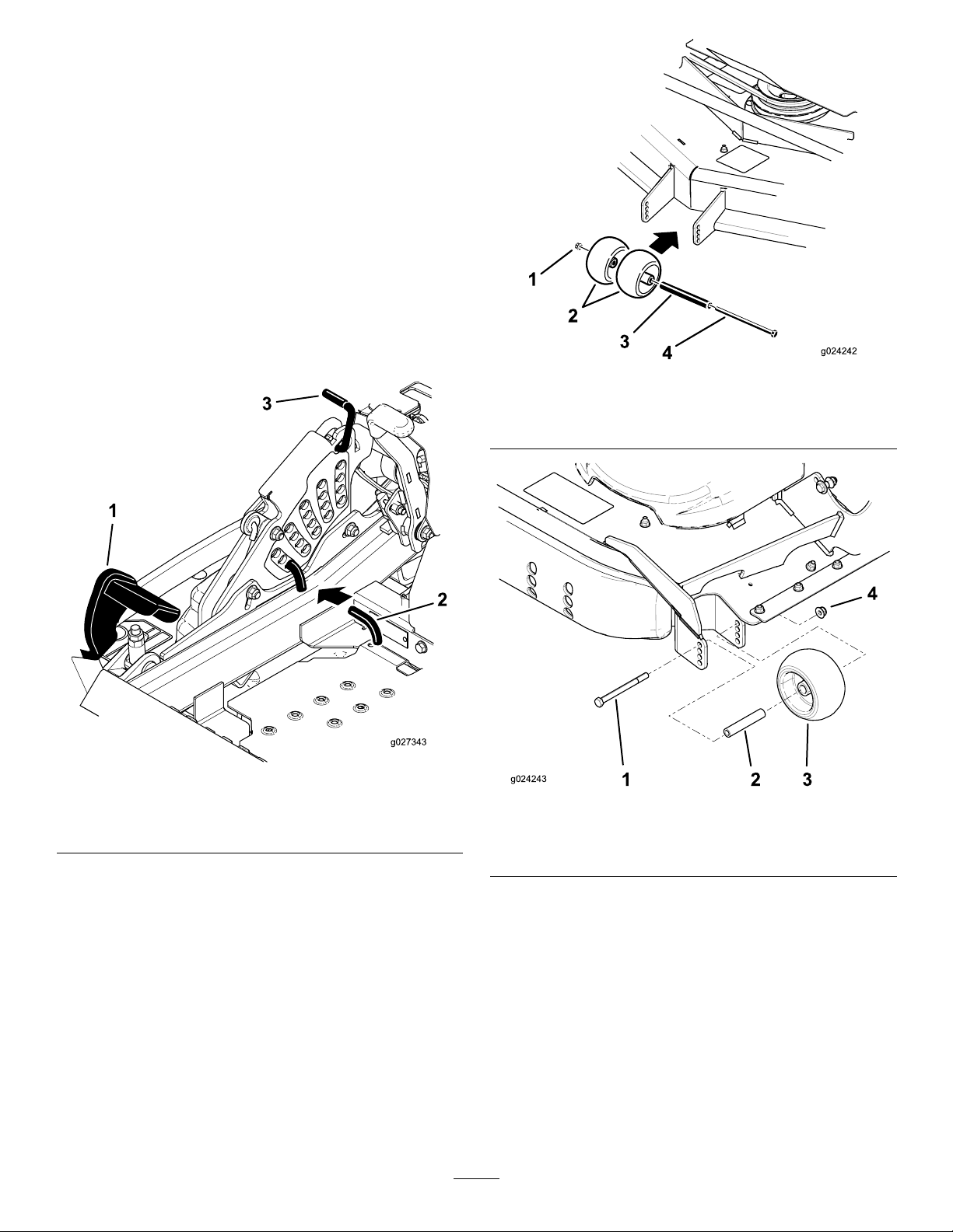
Theheight-of-cutisadjustedfrom25to140mm(1to
5-1/2inches)in6mm(1/4inch)incrementsbyrelocating
theclevispinintodifferentholelocations.
1.Movethetransportlocktothelockposition.
2.Pushonthedeckliftpedalwithyourfootandraisethe
mowerdecktothetransportposition(alsothe140mm
(5-1/2inch)cuttingheightposition)(Figure26).
3.Toadjust,rotatethepin90degreesandremovethepin
fromtheheight-of-cutbracket(Figure26).
4.Selectaholeintheheight-of-cutbracketcorresponding
totheheight-of-cutdesiredand,insertthepin(Figure
26).
5.Pushonthedecklift,pullbackonthetransportlock,
andslowlylowerthemowerdeck.
Figure27
1.FlangeNut3.Bushing
2.Anti-scalproller4.Bolt
Figure26
1.Deckliftpedal
2.Cutofheightpin
AdjustingtheAnti-Scalp Rollers
Wheneveryouchangetheheight-of-cut,itisrecommended
toadjusttheheightoftheanti-scalprollers.
1.Disengagetheblade-controlswitch(PTO),movethe
motion-controlleverstotheneutral-lockedposition
andsettheparkingbrake.
2.Stoptheengine,removethekey,andwaitforallmoving
partstostopbeforeleavingtheoperatingposition.
3.Adjusttheanti-scalprollersasshowninFigure27and
Figure28tomatchtheclosestheight-of-cutposition.
3.Transportlock
Figure28
1.Bolt3.Anti-scalproller
2.Bushing4.FlangeNut
AdjustingtheSkid(s)
Mounttheskidsinthelowerpositionwhenoperatingin
heightofcutshigherthan64mm(2-1/2inches)andinthe
higherpositionwhenoperatinginheightofcutslowerthan
64mm(2-1/2inches).
Note:Whentheskidsbecomeworn,switchtheskidtothe
oppositesidesofthemower,ippingthemover.Thiswill
allowyoutousetheskidslongerbeforereplacingthem.
1.DisengagethePTOandsettheparkingbrake.
24
Page 25
2.MovethethrottlelevertotheSlowposition,stopthe
g024244
1
2
3
g019754
g019755
g019768
1
engine,removethekey,andwaitforallmovingpartsto
stopbeforeleavingtheoperatingposition.
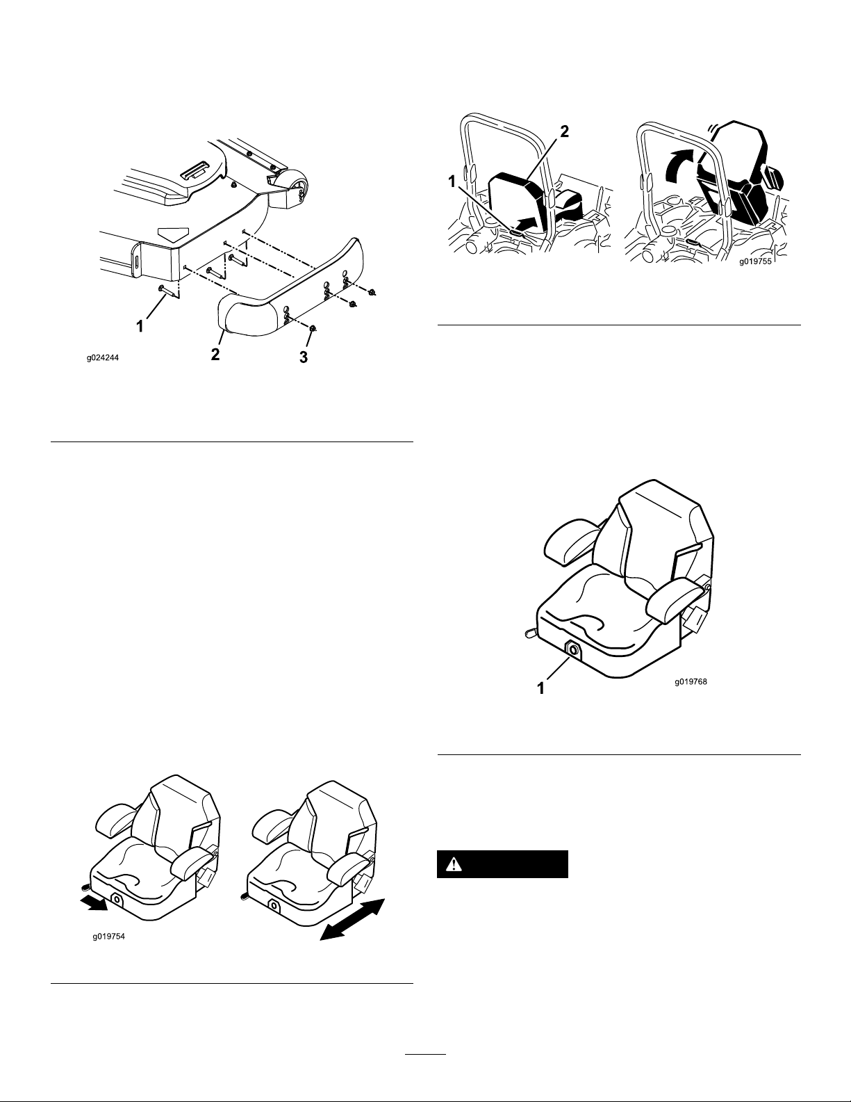
3.Removethecarriageboltsandnutsfromeachskid
(Figure29).
UnlatchingtheSeat
Note:Certainmodelswillhaveaxedseatandcannotbe
rotatedup.
Figure31
1.Seatlatch2.Seat
Figure29
1.Carriagebolt
2.Skid
4.Moveeachskidtothedesiredpositionandsecurethem
withthecarriageboltsandnuts.
Note:Onlyusethetoporcentersetsofholesto
adjusttheskids.Thebottomholesareusedwhen
switchingsidesonthemowerdeck,atwhichtimethey
becomethetopholesontheothersideofthemower.
5.Topreventdamagingtheskid,torquethecarriagebolts
andnutsforeachskidto12.4to14.7N-m(110to130
in-lb).
3.Nut
PositioningtheSeat
Theseatcanmoveforwardandbackward.Positiontheseat
whereyouhavethebestcontrolofthemachineandaremost
comfortable.
Toadjust,movetheleversidewaystounlockseat(Figure30).
ChangingtheSeatSuspension
Theseatisadjustabletoprovideasmoothandcomfortable
ride.Positiontheseatwhereyouaremostcomfortable.
Toadjustit,turntheknobinfronteitherdirectiontoprovide
thebestcomfort(Figure32).
Figure32
1.Seatsuspensionknob
UsingtheDrive-WheelRelease Valves
WARNING
Handsmaybecomeentangledintherotatingdrive
componentsbelowtheenginedeck,whichcould
resultinseriousinjury.
Figure30
Stoptheengine,removethekey ,andallowall
movingpartstostopbeforeaccessingthedrive
wheelreleasevalves.
25
Page 26
WARNING
g024246
g027406
TransportingtheMachine
Theengineandhydraulicdriveunitscanbecome
veryhot.Touchingahotengineorhydraulicdrive
unitscancausesevereburns.
Allowtheengineandhydraulicdriveunitstocool
completelybeforeaccessingthedrivewheelrelease
valves.
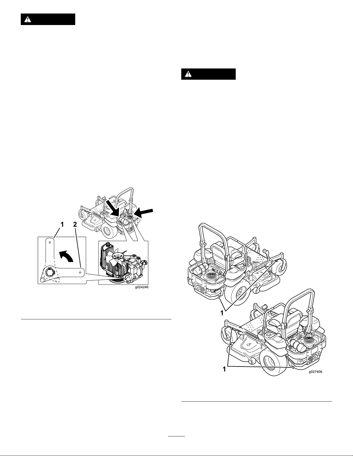
Thedrive-wheelreleasevalvesarelocatedinthebackofeach
hydraulicdriveunit,undertheseat.
Note:Makesurethereleasevalvesareinthefullyhorizontal
positionwhenoperatingthemachineorseveredamagetothe
hydraulicsystemcanoccur.
1.DisengagethePTO(blade-controlswitch)andturnthe
ignitionkeytooff.Movetheleverstoneutral-locked
positionandapplyparkingbrake.Removethekey.
2.Rotatethereleasevalveleversverticallytopushthe
machine.Thisallowshydraulicoiltoby-passthepump
enablingthewheelstoturn(Figure33).
3.Disengageparkingbrakebeforepushing.
Useaheavy-dutytrailerortrucktotransportthemachine.
Ensurethatthetrailerortruckhasallnecessarybrakes,
lighting,andmarkingasrequiredbylaw .Pleasecarefullyread
allthesafetyinstructions.Knowingthisinformationcould
helpyou,yourfamily,petsorbystandersavoidinjury.
WARNING
Drivingonthestreetorroadwaywithoutturn
signals,lights,reectivemarkings,oraslow
movingvehicleemblemisdangerousandcanlead
toaccidentscausingpersonalinjury.
Donotdrivemachineonapublicstreetorroadway.
Totransportthemachine:
1.Ifusingatrailer,connectittothetowingvehicleand
connectthesafetychains.
2.Ifapplicable,connectthetrailerbrakes.
3.Loadthemachineontothetrailerortruck.
4.Stoptheengine,removethekey,setthebrake,and
closethefuelvalve.
Figure33
1.Verticaltopushthe
machine
4.Rotatethereleasevalvelevershorizontallytorunthe
machine(Figure33).
2.Horizontaltorunthe
machine
5.Usethemetaltiedownloopsonthemachineto
securelyfastenthemachinetothetrailerortruckwith
straps,chains,cable,orropes(Figure34).
Figure34
1.Tractionunittiedownloops
26
Page 27
LoadingtheMachine
g028043
g027996
5
1
2
6
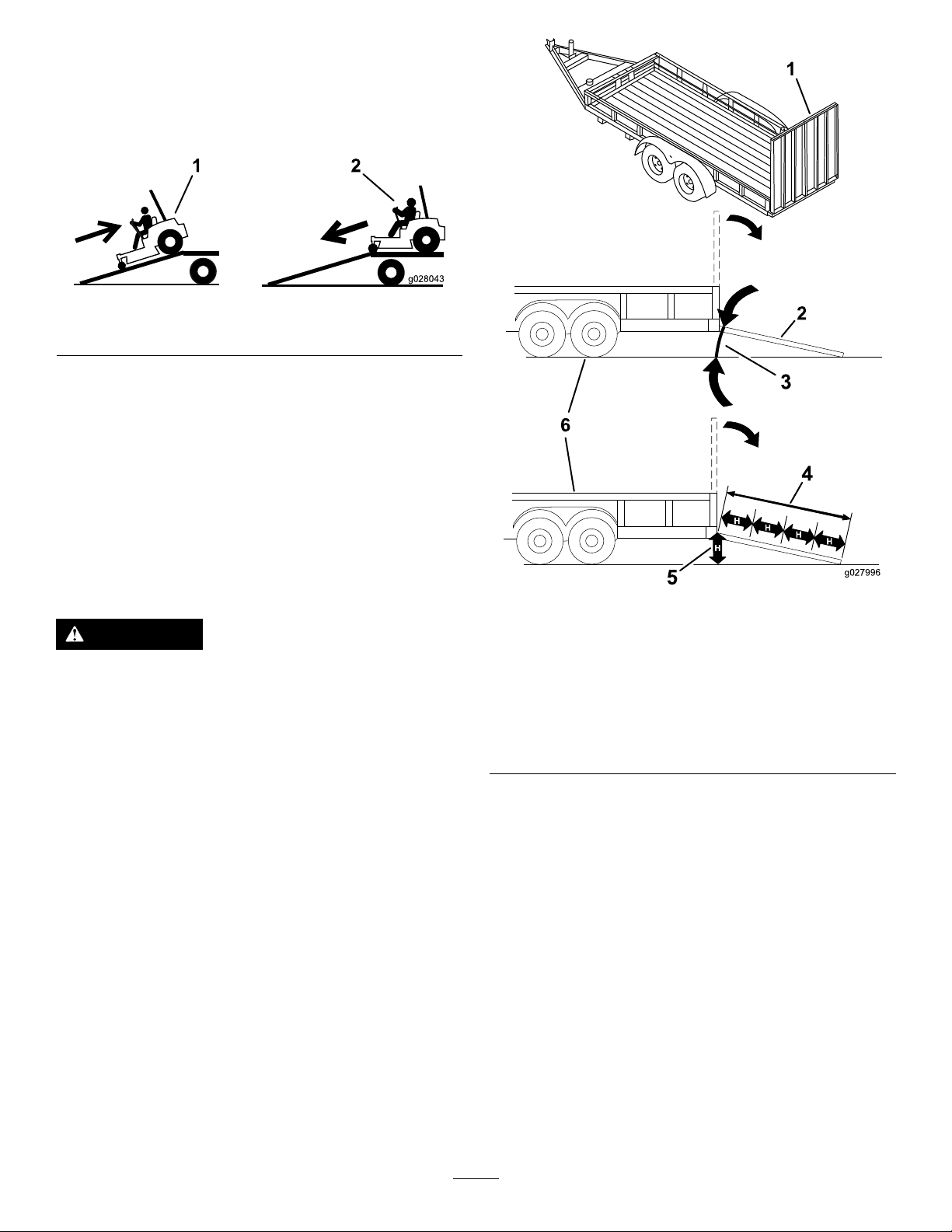
Useextremecautionwhenloadingorunloadingmachines
ontoatraileroratruck.Useafull-widthrampthatiswider
thanthemachineforthisprocedure.Backuprampsand
driveforwarddownramps(Figure35).
Figure35
1.Backupramps
2.Driveforwarddownramps
Important:Donotusenarrowindividualrampsfor
eachsideofthemachine.
Ensuretherampislongenoughsothattheanglewiththe
grounddoesnotexceed15degrees(Figure36).Onat
ground,thisrequiresaramptobeatleast4timesaslongas
theheightofthetrailerortruckbedtotheground.Asteeper
anglemaycausemowercomponentstogetcaughtastheunit
movesfromtheramptothetrailerortruck.Steeperangles
mayalsocausethemachinetotiporlosecontrol.Ifloading
onornearaslope,positionthetrailerortrucksothatitis
onthedownsideoftheslopeandtherampextendsupthe
slope.Thiswillminimizetherampangle.
WARNING
Loadingamachineontoatrailerortruckincreases
thepossibilityoftip-overandcouldcauseserious
injuryordeath.
•Useextremecautionwhenoperatingamachine
onaramp.
•EnsurethattheROPSisintheuppositionand
usetheseatbeltwhenloadingorunloadingthe
machine.EnsurethattheROPSwillclearthe
topofanenclosedtrailer.
•Useonlyafull-widthramp;donotuseindividual
rampsforeachsideofthemachine.
•Donotexceeda15-degreeanglebetweenthe
rampandthegroundorbetweentherampand
thetrailerortruck.
•Ensurethelengthoframpisatleast4timesas
longastheheightofthetrailerortruckbedto
theground.Thiswillensurethatrampangle
doesnotexceed15degreesonatground.
•Backuprampsanddriveforwarddownramps.
•Avoidsuddenaccelerationordecelerationwhile
drivingthemachineonarampasthiscould
causealossofcontroloratip-oversituation.
1.Full-widthrampinstowed
position
2.Sideviewoffull-width
rampinloadingposition
3.Notgreaterthan
15degrees
Figure36
4.Rampisatleast4times
aslongastheheightof
thetrailerortruckbedto
theground
5.H=heightofthetraileror
truckbedtotheground
6.Trailer
27
Page 28

OperatingTips
FastThrottleSetting
cuttingheighthigherthanusualandcutthegrassatthis
setting.Thencutthegrassagainusingthelower,normal
setting.
Forbestmowingandmaximumaircirculation,operate
theengineatthefastthrottleposition.Airisrequiredto
thoroughlycutgrassclippings,sodonotsettheheight-of-cut
solowastototallysurroundthemowerbyuncutgrass.
Alwaystrytohaveonesideofthemowerfreefromuncut
grass,whichallowsairtobedrawnintothemower.
CuttingaLawnfortheFirstTime
Cutgrassslightlylongerthannormaltoensurethecutting
heightofthemowerdoesnotscalpanyunevenground.
However,thecuttingheightusedinthepastisgenerallythe
bestonetouse.Whencuttinggrasslongerthansixinchestall,
youmaywanttocutthelawntwicetoensureanacceptable
qualityofcut.
Cut1/3oftheGrassBlade
Itisbesttocutonlyabout1/3ofthegrassblade.Cutting
morethanthatisnotrecommendedunlessgrassissparse,or
itislatefallwhengrassgrowsmoreslowly.
MowingDirection
WhenStopping
Ifyoumuststopthemachine'sforwardmotionwhilemowing,
aclumpofgrassclippingsmaydropontoyourlawn.Toavoid
this,moveontoapreviouslycutareawiththebladesengaged.
KeeptheUndersideoftheMowerClean
Cleanclippingsanddirtfromtheundersideofthemower
aftereachuse.Ifgrassanddirtbuildupinsidethemower,
cuttingqualitywilleventuallybecomeunsatisfactory.
BladeMaintenance
Maintainasharpbladethroughoutthecuttingseasonbecause
asharpbladecutscleanlywithouttearingorshreddingthe
grassblades.Tearingandshreddingturnsgrassbrownat
theedges,whichslowsgrowthandincreasesthechanceof
disease.Checkthecutterbladesdailyforsharpness,andfor
anywearordamage.Filedownanynicksandsharpenthe
bladesasnecessary.Ifabladeisdamagedorworn,replaceit
immediatelywithagenuineT ororeplacementblade.
Alternatemowingdirectiontokeepthegrassstanding
straight.Thisalsohelpsdisperseclippingswhichenhances
decompositionandfertilization.
MowatCorrectIntervals
Normally,moweveryfourdays.Butremember,grassgrows
atdifferentratesatdifferenttimes.Sotomaintainthesame
cuttingheight,whichisagoodpractice,mowmoreoftenin
earlyspring.Asthegrassgrowthrateslowsinmidsummer,
mowlessfrequently.Ifyoucannotmowforanextended
period,rstmowatahighcuttingheight;thenmowagain
twodayslateratalowerheightsetting.
CuttingSpeed
Toimprovecutquality,useaslowergroundspeedincertain
conditions.
AvoidCuttingTooLow
Ifthecuttingwidthofthemoweriswiderthanthemower
youpreviouslyused,raisethecuttingheighttoensurethat
uneventurfisnotcuttooshort.
LongGrass
Ifthegrassiseverallowedtogrowslightlylongerthan
normal,orifitcontainsahighdegreeofmoisture,raisethe
28
Page 29

Maintenance
RecommendedMaintenanceSchedule(s)
MaintenanceService
Interval
Aftertherst100hours
Aftertherst250hours
Beforeeachuseordaily
Every50hours
Every100hours
Every150hours
MaintenanceProcedure
•Checkthewheellugnuttorque.
•Checkthewheelhubslotted-nuttorque.
•Checktheparkingbrakeadjustment.
•Changethehydraulicltersandhydraulicoilwhenusinganytypeofoil.
•Checkthesafetysystem.
•Checktheengine-oillevel.
•Checktheseatbelt.
•Checktherolloverprotectionsystem(ROPS)knobs.
•Cleantheenginescreenandtheoilcooler.
•Checkandcleanthehydraulicunitshrouds.
•Checkthemowerblades.
•Cleanthemowerdeck.
•Greasethemowerdeckspindles.
•Checksparkarrester(ifequipped).
•Checkthetirepressure.
•Inspectthebeltsforcracksandwear.
•Checkthehydraulicoillevel.
•Lubricatethemowerdeckliftpivots.
•Changetheengineoil(moreoftenindirtyordustyconditions).
•Checkandcleanenginecoolingnsandshrouds.
•Inspecttheprimarylterandairinletscreen.
Every200hours
Every250hours
Every300hours
Every500hours
Every600hours
Yearlyorbeforestorage
•Changetheengineoillter.
•Cleantheengine-oilcooler.
•Check,cleanandregapthesparkplug.
•Replacethefuellter.(moreoftenindirtyordustyconditions).
•ChangethehydraulicltersandhydraulicoilwhenusingMobil®1oil(moreoftenin
dirtyordustyconditions).
•Replacetheprimaryairlter(moreoftenindustyorsandyconditions).
•Checktheinnerairlter.
•Checkthewheellugnuttorque.
•Checkthewheelhubslotted-nuttorque.
•Adjustthecaster-pivotbearing.
•Checktheparkingbrakeadjustment.
•ChangethehydraulicltersandhydraulicoilwhenusingToro®HYPR-OIL™500
hydraulicoil(moreoftenindirtyordustyconditions).
•Replacetheinnerairlter.
Monthly
Yearly
•Checkthebattery .
•Greasethepump-beltidlerarm.
•Greasethefrontcasterpivots(moreoftenindirtyordustyconditions).
•Repackthefrontcasterwheelbearings(moreoftenindirtyordustyconditions).
•Greasethemower-deckidlerarms.
•Lubricatethecasterwheelhubs
•Paintchippedsurfaces.
•Checkallmaintenanceprocedureslistedabovebeforestorage.
Important:Refertoyourengineoperator'smanualforadditionalmaintenanceprocedures.
29
Page 30
CAUTION
G017050
Ifyouleavethekeyintheignitionswitch,someonecouldaccidentlystarttheengineandseriouslyinjure
youorotherbystanders.
Removethekeyfromtheignitionbeforeyoudoanymaintenance.
Lubrication
GreasingandLubrication
Greasemorefrequentlywhenoperatingconditionsare
extremelydustyorsandy.
GreaseType:No.2general-purpose,lithium-basedor
molybdenum-basedgrease
1.Disengagetheblade-controlswitch(PTO),movethe
motioncontrolleverstotheneutral-lockedposition
andsettheparkingbrake.
2.Stoptheengine,removethekey,andwaitforallmoving
partstostopbeforeleavingtheoperatingposition.
3.Cleanthegreasettingswitharag.Makesuretoscrape
anypaintoffthefrontofthetting(s).
4.Connectagreaseguntothetting.Pumpgrease
intothettingsuntilgreasebeginstooozeoutofthe
bearings.
5.Wipeupanyexcessgrease.
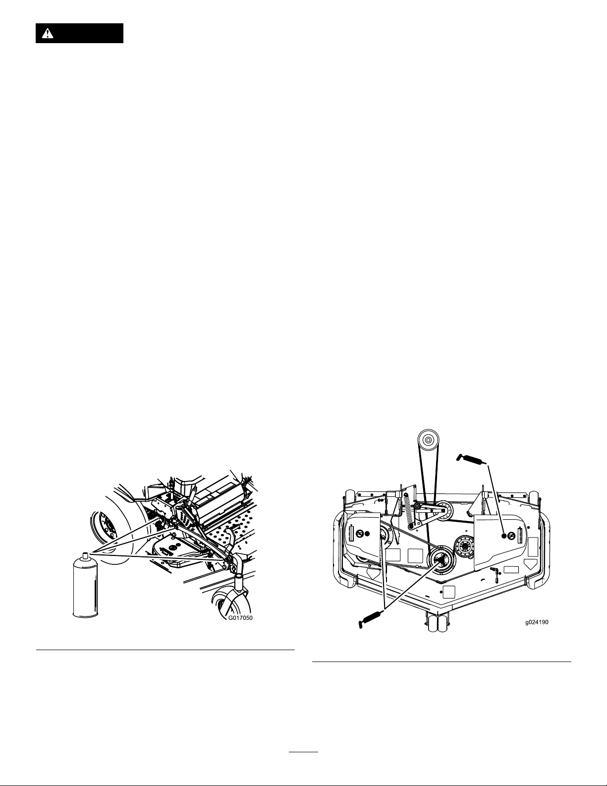
AddingLightOilorSprayLubrication
GreasingtheMower
ServiceInterval:Every50hours—Greasethemowerdeck
spindles.
Yearly—Greasethepump-beltidlerarm.
Yearly—Greasethefrontcasterpivots(moreoftenin
dirtyordustyconditions).
Yearly—Repackthefrontcasterwheelbearings(more
oftenindirtyordustyconditions).
Yearly—Greasethemower-deckidlerarms.
Important:Makesurecuttingunitspindlesarefullof
greaseweekly.
1.Disengagetheblade-controlswitch(PTO),movethe
motion-controlleverstotheneutral-lockedposition,
andsettheparkingbrake.
2.Stoptheengine,removethekey,andwaitforallmoving
partstostopbeforeleavingtheoperatingposition.
3.Greasethemowerdeckidlerpulleypivotuntilgrease
comeoutthebottom(Figure38).
4.Greasethethreespindlebearingsuntilgreasecomes
outthelowerseals(Figure38).
ServiceInterval:Every100hours
Lubricatethedeckliftpivots.
Figure37
Figure38
5.Greasethedeck-beltidlerarms(Figure39).
30
Page 31
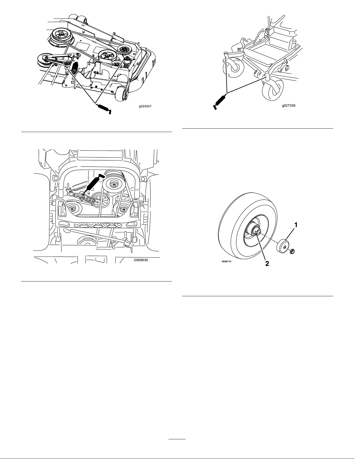
Figure39
g027339
Figure41
6.Greasethedrive-beltidlerarm(Figure38).
Figure40
7.Removethedustcapandadjustthecasterpivots.
Keepthedustcapoffuntilgreasingisdone.Referto
AdjustingtheCaster-PivotBearing(page44).
8.Removethehexplug.Threadagreasettingintothe
hole.
9.Pumpgreaseintothegreasettinguntilitoozesout
aroundthetopbearing.
10.Removethegreasettinginthehole.Installthehex
pluganddustcap(Figure41).
LubricatingtheCasterWheel Hubs
ServiceInterval:Yearly
1.Stoptheengine,waitforallmovingpartstostop,and
removethekey.Engagetheparkingbrake.
Figure42
1.Sealguard2.Spacernutwithwrench
ats
2.Removethecasterwheelfromthecasterforks.
3.Removethesealguardsfromthewheelhub.
4.Removeoneofthespacernutsfromtheaxleassembly
inthecasterwheel.Notethatthreadlockingadhesive
hasbeenappliedtolockthespacernutstotheaxle.
Removetheaxle(withtheotherspacernutstill
assembledtoit)fromthewheelassembly .
5.Pryoutseals,andinspectbearingsforwearordamage
andreplaceifnecessary.
6.Packthebearingswithageneral-purposegrease.
7.Insertonebearing,onenewsealintothewheel.
Note:Replacetheseals.
8.Iftheaxleassemblyhashadbothspacernutsremoved
(orbrokenloose),applyathreadlockingadhesive
toonespacernutandthreadontotheaxlewiththe
31
Page 32
wrenchatsfacingoutward.Donotthreadspacer
g012996
3
4
1
2
nutallofthewayontotheendoftheaxle.Leave
approximately3mm(1/8inch)fromtheoutersurface
ofthespacernuttotheendoftheaxleinsidethenut.
9.Inserttheassemblednutandaxleintothewheelonthe
sideofthewheelwiththenewsealandbearing.
10.Withtheopenendofthewheelfacingup,llthearea
insidethewheelaroundtheaxlefullofgeneral-purpose
grease.
EngineMaintenance
WARNING
Contactwithhotsurfacesmaycausepersonal
injury.
Keephands,feet,face,clothingandotherbody
partsawaythemuferandotherhotsurfaces.
11.Insertthesecondbearingandnewsealintothewheel.
12.Applyathreadlockingadhesivetothe2ndspacernut
andthreadontotheaxlewiththewrenchatsfacing
outward.
13.Torquethenutto8-9N-m(75-80in-lb),loosen,then
re-torqueto2-3N-m(20-25in-lb).Makesureaxle
doesnotextendbeyondeithernut.
14.Reinstallthesealguardsoverthewheelhubandinsert
wheelintocasterfork.Reinstallcasterboltandtighten
nutfully.
Important:T opreventsealandbearingdamage,check
thebearingadjustmentoften.Spinthecastertire.The
tireshouldnotspinfreely(morethan1or2revolutions)
orhaveanysideplay.Ifthewheelspinsfreely,adjust
torqueonspacernutuntilthereisaslightamountof
drag.Applythreadlockingadhesive.
ServicingtheAirCleaner
ServiceInterval:Every150hours
Every300hours/Yearly(whichevercomes
rst)—Replacetheprimaryairlter(moreoftenin
dustyorsandyconditions).
Every300hours—Checktheinnerairlter.
Every600hours—Replacetheinnerairlter.
Note:Checktheltersmorefrequentlyiftheoperating
conditionsareextremelydustyorsandy.
RemovingtheFilters
1.DisengagethePTO ,movethemotion-controlleversto
theneutral-lockedposition,andsettheparkingbrake.
2.Stoptheengine,removethekey,andwaitforallmoving
partstostopbeforeleavingtheoperatingposition.
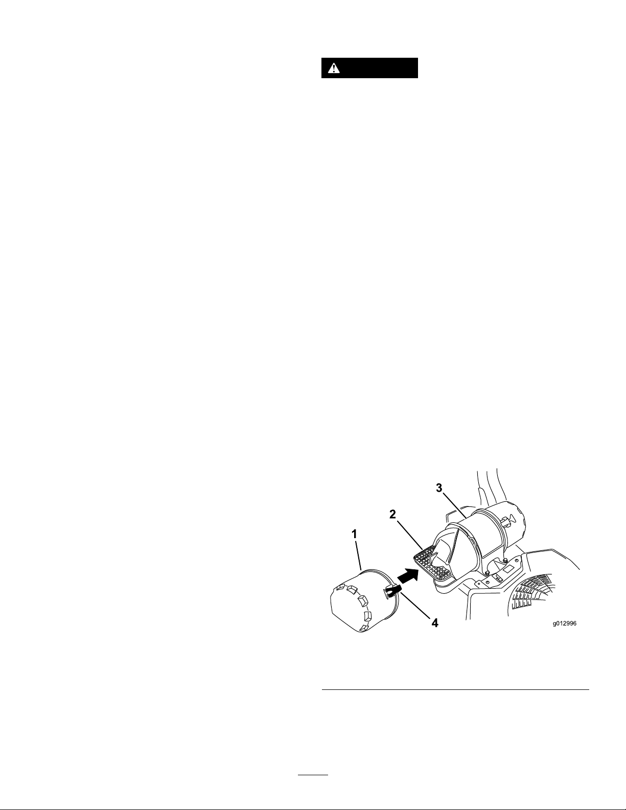
3.Releasethelatchesontheaircleanerandpulltheair
inletcoverofftheaircleanerbody(Figure43).
4.Cleantheairinletscreenandcover.
5.Installtheairinletcoverandsecureitwiththelatches
(Figure43).
Figure43
1.Airinletcover3.Aircleanerbody
2.Airinletscreen4.Latch
6.Releasethelatchesontheaircleanerandpulltheair
cleanercoverofftheaircleanerbody(Figure44).
7.Cleantheinsideoftheaircleanercoverwith
compressedair.
32
Page 33
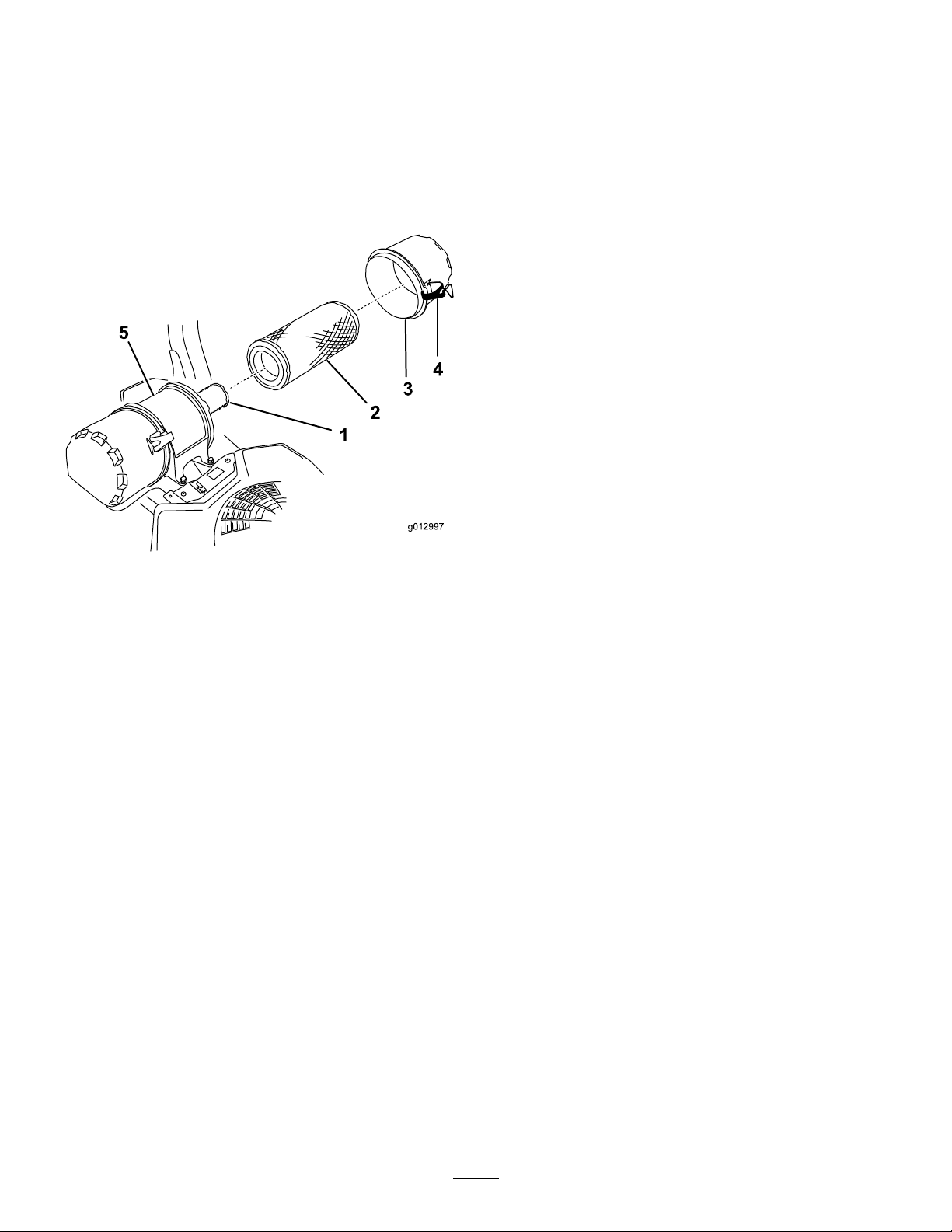
8.Gentlyslidetheprimarylteroutoftheaircleaner
g012997
1
2
3
4
5
body(Figure44).
2.Iftheinnerlterisbeingreplaced,carefullyslideitinto
thelterbody(Figure44).
Note:Avoidknockingthelterintothesideofthe
body.
9.Removetheinnerlteronlyifyouintendtoreplaceit.
Important:Neverattempttocleantheinnerlter.
Ifthesafetylterisdirty,thentheprimarylteris
damaged.Replacebothlters.
3.Carefullyslidetheprimarylterovertheinnerlter
(Figure44).
Note:Ensurethattheprimarylterisfullyseatedby
pushingonitsouterrimwhileinstallingit.
Important:Donotpressonthesoftinsidearea
ofthelter.
4.Installtheaircleanercoverandsecurethelatches
(Figure44).
Figure44
1.Innerlter
2.Primarylter
3.Aircleanercover
4.Latch
5.Aircleanerbody
10.Inspecttheprimarylterfordamagebylookinginto
thelterwhileshiningabrightlightontheoutsideof
thelter.Holesinthelterwillappearasbrightspots.
Ifthelterisdamaged,discardit.
ServicingthePrimaryFilter
•Iftheprimarylterisdirty,bent,ordamaged,replaceit.
•Donotcleantheprimarylter.
ServicingtheSafetyFilter
Replacethesafetylter,nevercleanit.
Important:Neverattempttocleanthesafetylter.
Ifthesafetylterisdirty,thentheprimarylteris
damaged.Replacebothlters.
InstallingtheFilters
Important:Topreventenginedamage,alwaysoperate
theenginewithbothairltersandcoverinstalled.
1.Ifinstallingnewlters,checkeachlterforshipping
damage.Donotuseadamagedlter.
33
Page 34
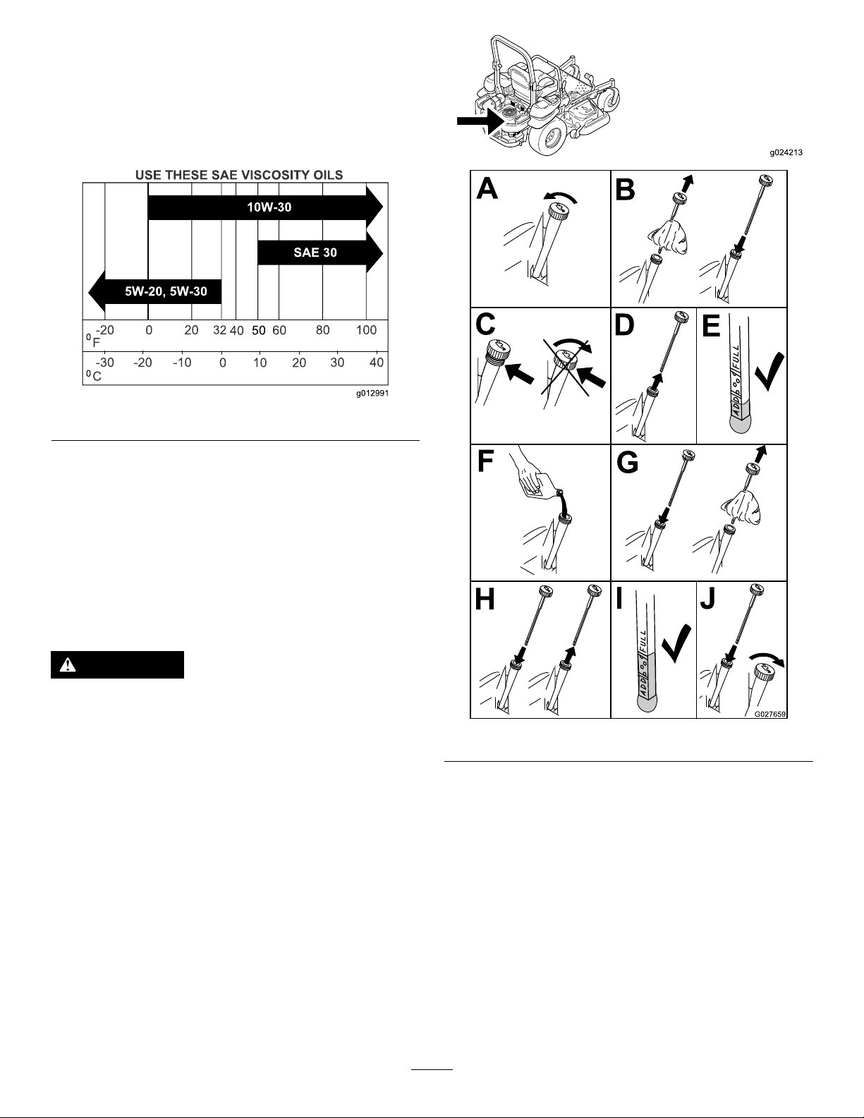
ServicingtheEngineOil
g012991
0
0
50
SAE 30
g024213
B
A
C
D
E
G027659
F
G
H
I J
OilType:Detergentoil(APIserviceclassSJorhigher)
OilCapacity:withalterchange,1.7L(58oz;withnolter
change,1.4L(48oz)
Viscosity:Seethetablebelow.
Figure45
Note:Useofsyntheticoilhaving5W-20or5W-30ratingis
acceptable,upto4degreesC(40degreesF).
Note:Syntheticoilswillprovidebetterstartinginextreme
coldbelow-23degreesC(-10degreesF).
CheckingtheEngine-OilLevel
ServiceInterval:Beforeeachuseordaily
Note:Checktheoilwhentheengineiscold.
WARNING
Contactwithhotsurfacesmaycausepersonal
injury.
Keephands,feet,face,clothingandotherbody
partsawayfromthemuferandotherhotsurfaces.
Important:Donotoverllthecrankcasewithoil
becausedamagetotheenginemayresult.Donotrun
enginewithoilbelowthelowmarkbecausetheengine
maybedamaged.
1.DisengagethePTO ,movethemotion-controlleversto
theneutral-lockedpositionandsettheparkingbrake.
Figure46
2.Stoptheengine,removethekey,andwaitforall
movingpartstostopbeforeleavingtheoperating
position(Figure46).
34
Page 35

ChangingtheEngineOil
g024213
B
A
C
D
E
F
g027660
ServiceInterval:Every100hours(moreoftenindirtyor
dustyconditions).
Note:Disposeoftheusedoilatarecyclingcenter.
1.Parkthemachinesothattherearisslightlylowerthan
thefronttoensuretheoildrainscompletely.
2.DisengagethePTO ,movethemotion-controlleversto
theneutral-lockedpositionandsettheparkingbrake.
3.Stoptheengine,removethekey,andwaitforall
movingpartstostopbeforeleavingtheoperating
position(Figure47).
4.Slowlypourapproximately80%ofthespeciedoil
intothellertubeandslowlyaddtheadditionaloilto
bringittotheFullmark(Figure48).
Figure48
5.Starttheengineanddrivetoaatarea.Checktheoil
levelagain.
ChangingtheEngine-OilFilter
ServiceInterval:Every200hours
Note:Changetheengineoilltermorefrequentlywhen
operatingconditionsareextremelydustyorsandy.
1.Draintheoilfromtheengine;refertoChangingthe
EngineOil(page35).
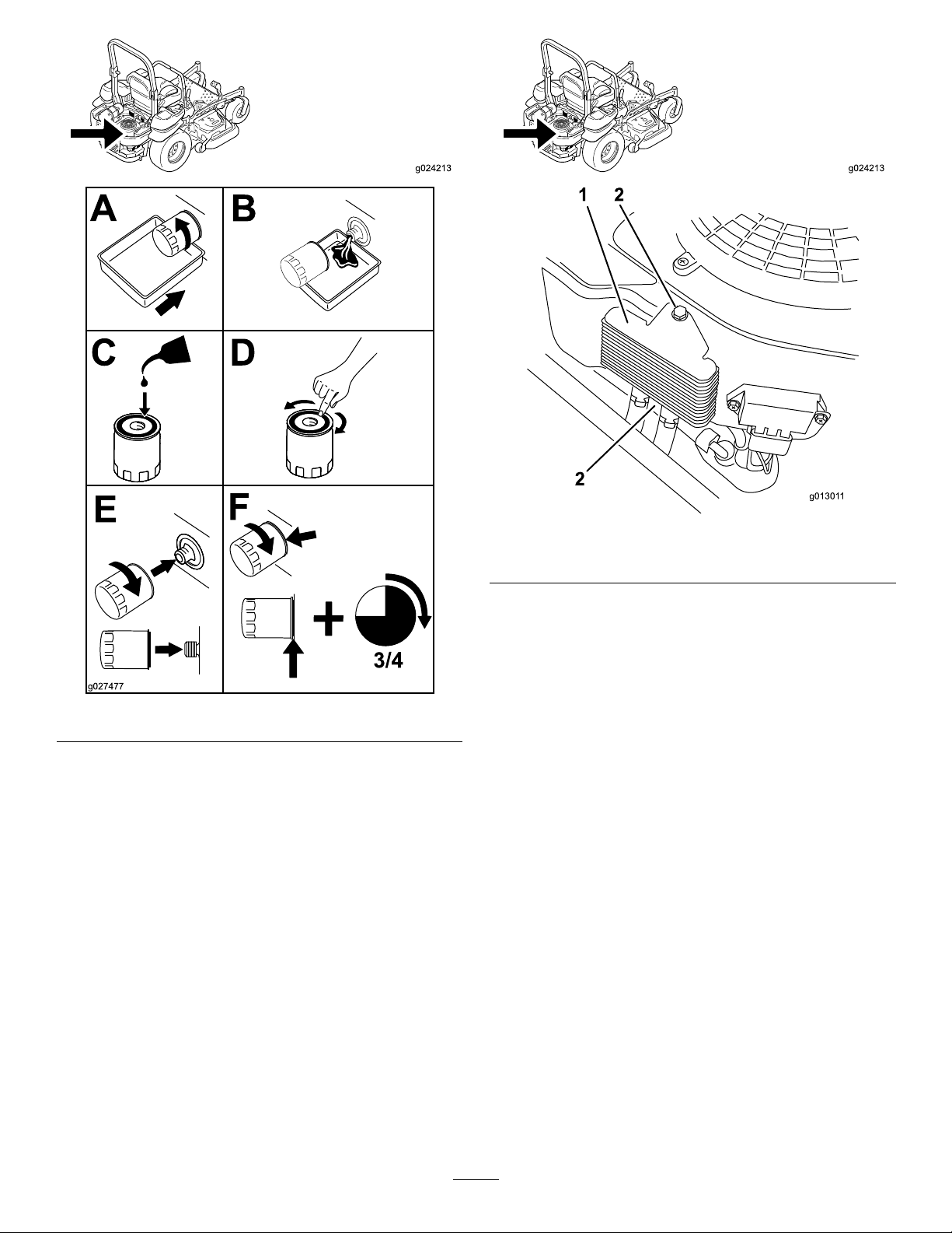
2.Changetheengineoillter(Figure49).
Figure47
35
Page 36
g024213
B
A
C D
E
F
3/4
g027477
Figure49
g024213
g01301 1
1 2
2
Figure50
1.Engine-oilcooler2.Bolts
Note:Ensuretheoilltergaskettouchestheengine
andthenanextra3/4turniscompleted.
3.Fillthecrankcasewiththepropertypeofnewoil;refer
toChangingtheEngineOil(page35).
ServicingtheEngine-OilCooler
ServiceInterval:Every200hours
1.Keeptheoilcoolerfreeofdebris.bycleaningthens
withabrush.
2.Removetheboltsholdingtheoilcoolertotheengine
housing.
3.Cleantheinsideoftheoilcoolerwithabrush.
4.Installtheoilcoolertotheenginehousing.
36
Page 37
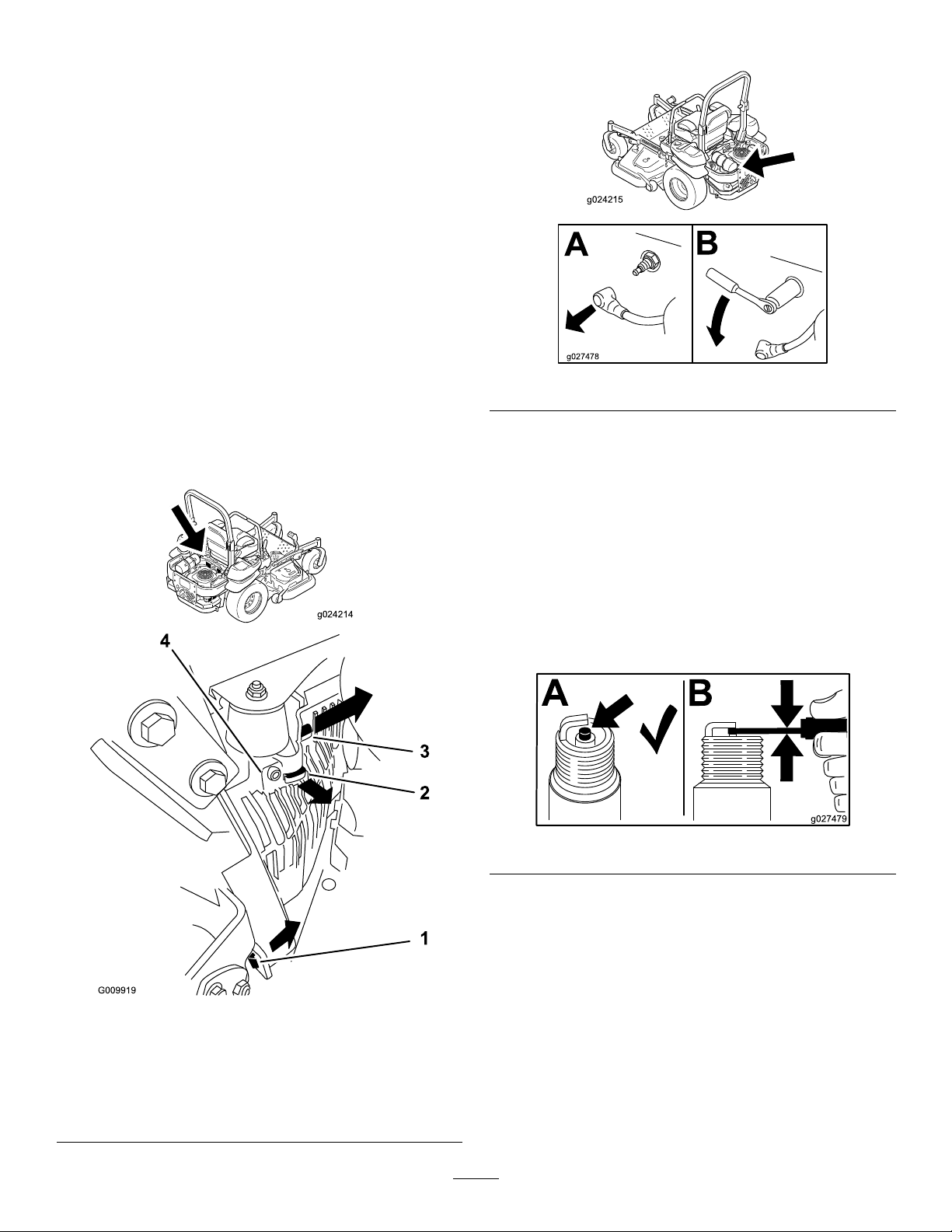
ServicingtheSparkPlug
g024214
g024215
B
A
g027478
B
A
g027479
ServiceInterval:Every200hours—Check,cleanandregap
thesparkplug.
Makesuretheairgapbetweenthecenterandsideelectrodes
iscorrectbeforeinstallingthesparkplug.Useasparkplug
wrenchforremovingandinstallingthesparkplug(s)anda
gappingtool/feelergaugetocheckandadjusttheairgap.
Installanewsparkplug(s)ifnecessary.
Type:Champion
equivalent
AirGap:0.76mm(0.030inch)
®
XC12YC,Champion
RemovingtheSparkPlug
1.Stoptheengine,removethekey,andwaitforallmoving
partstostopbeforeleavingtheoperatingposition.
2.DisengagethePTO ,movethemotion-controlleversto
theneutral-lockedpositionandsettheparkingbrake.
3.Removethelefthandhydraulicunitshroudintheorder
listedwithFigure51.Thisgivesyouaccesstothefront
sparkplug.
®
Platinum3071or
4.Removethesparkplug.
Figure52
5.Installthelefthandhydraulicunitshroud(Figure51).
CheckingtheSparkPlug
Important:Replacethesparkplug(s)whenithas:a
blackcoating,wornelectrodes,anoilylm,cracksor
reuseisquestionable.
Ifyouseelightbrownorgrayontheinsulator,theengineis
operatingproperly .Ablackcoatingontheinsulatorusually
meanstheaircleanerisdirty.
Setthegapto0.76mm(0.030inch).
Figure53
1.Pullthistabouttothe
sideinthedirectionofthe
arrow
2.Pulltheshroudoffofthis
frametabinthedirection
ofthearrow
Figure51
3.Pulltheshroudoffofthis
frametabinthedirection
ofthearrow
4.Shroud
37
Page 38
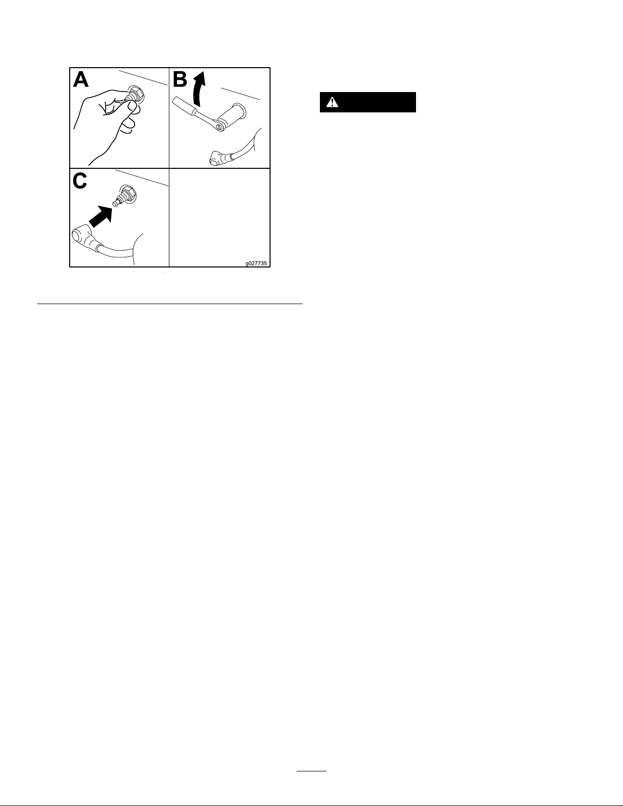
InstallingtheSparkPlug
CheckingtheSparkArrester
Tightenthesparkplug(s)to24.4-29.8N-m(18-22ft-lb).
Figure54
(ifequipped)
ServiceInterval:Every50hours
WARNING
Hotexhaustsystemcomponentsmayignite
gasolinevaporsevenaftertheengineisstopped.
Hotparticlesexhaustedduringengineoperation
mayigniteammablematerials.Firemayresultin
personalinjuryorpropertydamage.
Donotrefuelorrunengineunlesssparkarrester
isinstalled.
1.Stopengine,waitforallmovingpartstostop,and
removekey.Engageparkingbrake.
2.Waitformufertocool.
3.Ifanybreaksinthescreenorweldsareobserved,
replacethearrester.
4.Ifpluggingofthescreenisobserved,removethe
arresterandshakelooseparticlesoutofthearrester
andcleanscreenwithawirebrush(soakinsolventif
necessary).Reinstallarresteronexhaustoutlet.
38
Page 39
FuelSystem
G008963
12
3
Maintenance
WARNING
Fuelsystemcomponentsareunderhighpressure.
Theuseofimpropercomponentscanresultin
systemfailure,gasolineleakageandpossible
explosion.
Useonlyapprovedfuellinesandfuellters.
ServicingtheElectronic Fuel-InjectionSystem
Thismachinecontainsanelectronicfuel-injectionsystem.It
controlsthefuelowunderdifferentoperatingconditions.
Theelectroniccontrolunit(ECU)continuouslymonitorsthe
operationoftheEFIsystem.
Ifaproblemorfaultwithinthesystemisdetected,the
malfunctionindicatorlight(MIL)isilluminated.TheMILis
theredlightlocatedintherightconsolepanel.
OncetheMILilluminates,performinitialtroubleshooting
checks.RefertotheMILsectionunderTroubleshooting
(page65).
Ifthesechecksdonotcorrecttheproblem,furtherdiagnosis
andservicingbyanAuthorizedServiceDealerisnecessary.
ReplacingtheLow-Pressure FuelFilter
ServiceInterval:Every200hours/Yearly(whichevercomes
rst)(moreoftenindirtyordusty
conditions).
Thefuellterislocatedneartheengineonthefrontorrear
sideoftheengine.
1.DisengagethePTO ,movethemotion-controlleversto
theneutral-lockedposition,andsettheparkingbrake.
2.Stoptheengine,removethekey,andwaitforallmoving
partstostopbeforeleavingtheoperatingposition.
3.Allowthemachinetocooldown.
4.Stoptheengine,removethekey,andwaitforallmoving
partstostopbeforeleavingtheoperatingposition.
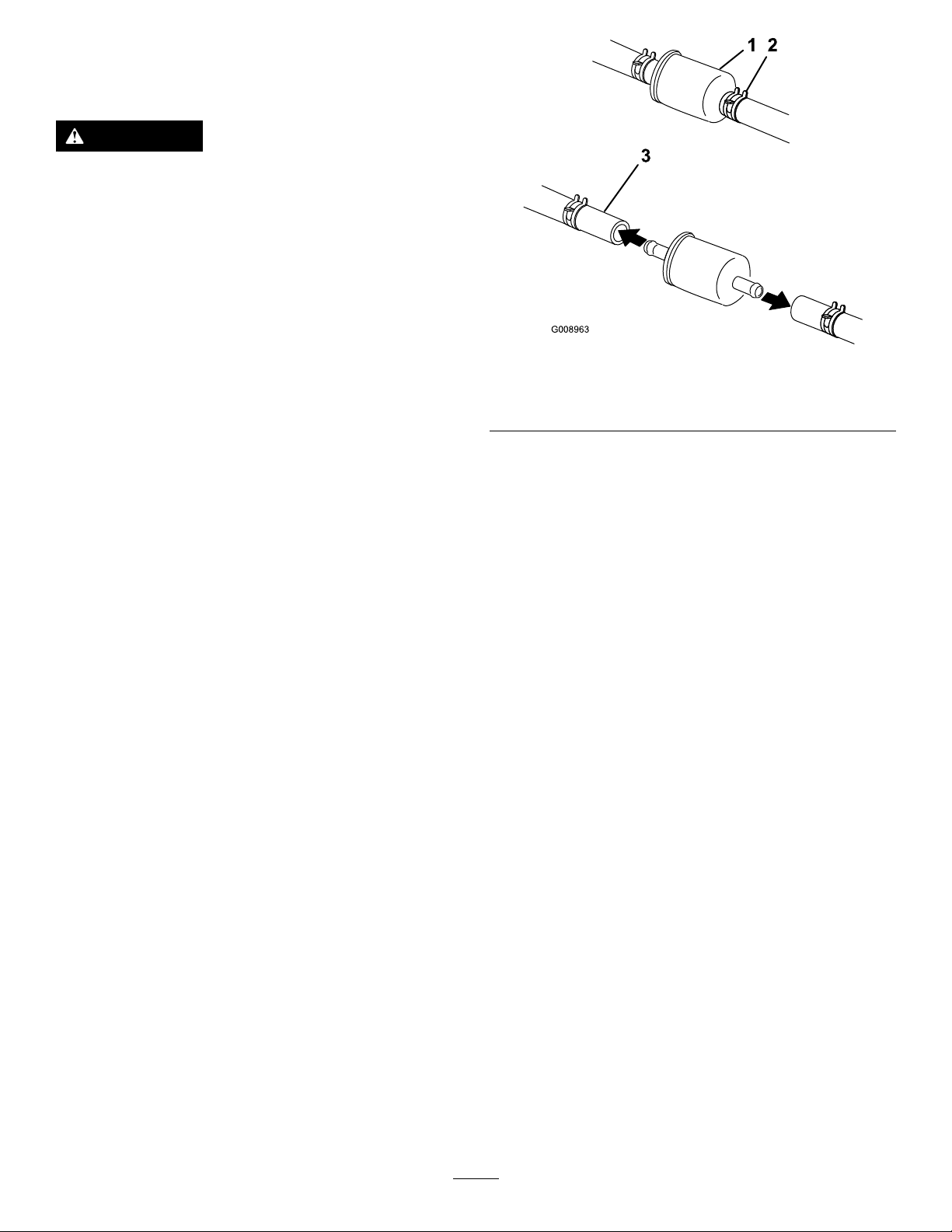
5.Closethefuelshutoffvalveundertheseat(Figure55).
Figure55
1.Fuellter
2.Hoseclamp
6.Squeezetheendsofthehoseclampstogetherandslide
themawayfromthelter(Figure55).
7.Removethelterfromthefuellines.
8.Installanewlterandmovethehoseclampscloseto
thelter(Figure55).
9.Openthefuelshutoffvalve.
Note:Itisimportanttoreinstallthefuellinehosesand
securewithplastictiesthesameastheywereoriginally
installedatthefactorytokeepthefuellineawayfrom
componentsthatcouldcausefuellinedamage.
3.Fuelline
ServicingtheHigh-Pressure FuelFilter
Donotattempttoservicethehighpressurefuellter.The
highpressurelterisintegratedwithinthefuelpumpmodule.
Thefuellterandothercomponentsinsidethefuelpump
modulearenotservicable.Donotattempttoopenthefuel
pumpmodule.
EnsurethatanAuthorizedServiceDealerreplacesthefuel
pumpmodulewiththehighpressurefuellter.
ServicingtheFuelTank
Donotattempttodrainthefueltank.Ensurethatan
AuthorizedServiceDealerdrainsthefueltank.
39
Page 40
ElectricalSystem
Maintenance
ServicingtheBattery
ServiceInterval:Monthly
WARNING
CALIFORNIA
Proposition65Warning
Batteryposts,terminals,andrelated
accessoriescontainleadandleadcompounds,
chemicalsknowntotheStateofCalifornia
tocausecancerandreproductiveharm.
W ash hands after handling .
DANGER
Batteryelectrolytecontainssulfuricacidwhichisa
deadlypoisonandcausessevereburns.
Donotdrinkelectrolyteandavoidcontactwith
skin,eyesorclothing.Wearsafetyglassestoshield
youreyesandrubberglovestoprotectyourhands.
WARNING
Incorrectbatterycableroutingcoulddamagethe
machineandcablescausingsparks.Sparkscan
causethebatterygassestoexplode,resultingin
personalinjury.
•AlwaysDisconnectthenegative(black)battery
cablebeforedisconnectingthepositive(red)
cable.
•AlwaysReconnectthepositive(red)battery
cablebeforereconnectingthenegative(black)
cable.
1.Disengagetheblade-controlswitch(PTO),movethe
motion-controlleverstotheneutral-lockedposition
andsettheparkingbrake.
2.Stoptheengine,removethekey,andwaitforallmoving
partstostopbeforeleavingtheoperatingposition.
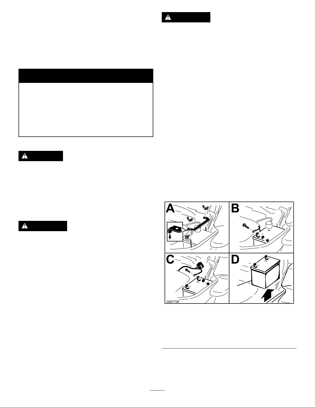
3.Firstdisconnectthenegativebatterycable(black)from
thenegative(-)(black)batteryterminal(Figure56).
4.Slidetheredterminalbootoffthepositive(red)battery
terminalandremovethepositive(+)(red)batterycable
(Figure56).
5.Removethewingnutsecuringthebatteryclamp
(Figure56).
6.Removetheclamp(Figure56).
7.Removethebattery.
RemovingtheBattery
WARNING
Batteryterminalsormetaltoolscouldshortagainst
metalmachinecomponentscausingsparks.Sparks
cancausethebatterygassestoexplode,resulting
inpersonalinjury.
•Whenremovingorinstallingthebattery,donot
allowthebatteryterminalstotouchanymetal
partsofthemachine.
•Donotallowmetaltoolstoshortbetween
thebatteryterminalsandmetalpartsofthe
machine.
Figure56
1.Removethewingnutand
clamp
2.Removethenegative
batterycablebeforethe
positive
3.Removethepositive
batterycable
4.Removebattery
InstallingtheBattery
1.Positionbatteryinthetraywiththeterminalposts
oppositefromthehydraulictank(Figure56).
40
Page 41
2.First,installthepositive(red)batterycabletopositive
(+)batteryterminal.
3.Theninstallthenegative(black)batterycableand
groundwiretothenegative(-)batteryterminal.
4.Securethecableswith2bolts,2washers,and2locknuts
(Figure56).
5.Slidetheredterminalbootontothepositive(red)
batterypost.
6.Installtheclampandsecureitwiththewingnut(Figure
56).
ChargingtheBattery
WARNING
Chargingthebatteryproducesgassesthatcan
explode.
Neversmokenearthebatteryandkeepsparksand
amesawayfrombattery.
Important:Alwayskeepthebatteryfullycharged
(1.265specicgravity).Thisisespeciallyimportantto
preventbatterydamagewhenthetemperatureisbelow
0°C(32°F).
1.Chargebatteryfor10to15minutesat25to30amps
or30minutesat10amps.
2.Whenthebatteryisfullycharged,unplugthecharger
fromtheelectricaloutlet,thendisconnectthecharger
leadsfromthebatteryposts(Figure57).
ServicingtheFuses
Theelectricalsystemisprotectedbyfuses.Itrequires
nomaintenance,however,ifafuseblowscheckthe
component/circuitforamalfunctionorshort.
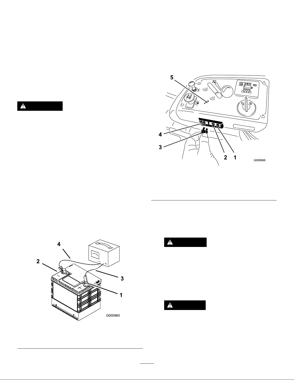
1.Thefusesarelocatedonrighthandconsolenextto
theseat(Figure58).
2.Toreplacethefuses,pulloutonthefusetoremoveit.
3.Installanewfuse(Figure58).
Figure58
1.Optionalaccesory-15amp
2.Charge-25amp5.Console
3.PTO-10amp
4.Main-25amp
3.Installthebatteryinthemachineandconnectthe
batterycables,refertoInstallingtheBattery(page40).
Note:Donotrunthemachinewiththebattery
disconnected,electricaldamagemayoccur.
Figure57
1.Positivebatterypost
2.Negativebatterypost
3.Red(+)chargerlead
4.Black(-)chargerlead
JumpStartingtheMachine
1.Checkandcleancorrosionfromthebatteryterminals
beforejumpstarting.Ensuretheconnectionsaretight.
CAUTION
Corrosionorlooseconnectionscancause
unwantedelectricalvoltagespikesatanytime
duringthejumpstartingprocedure.
Donotattempttojumpstartwithlooseor
corrodedbatteryterminalsordamagetothe
engineorEFImayoccur.
DANGER
Jumpstartingaweakbatterythatiscracked,
frozen,haslowelectrolytelevel,oran
open/shortedbatterycell,cancausean
explosionresultinginseriouspersonalinjury.
Donotjumpstartaweakbatteryifthese
conditionsexist.
41
Page 42
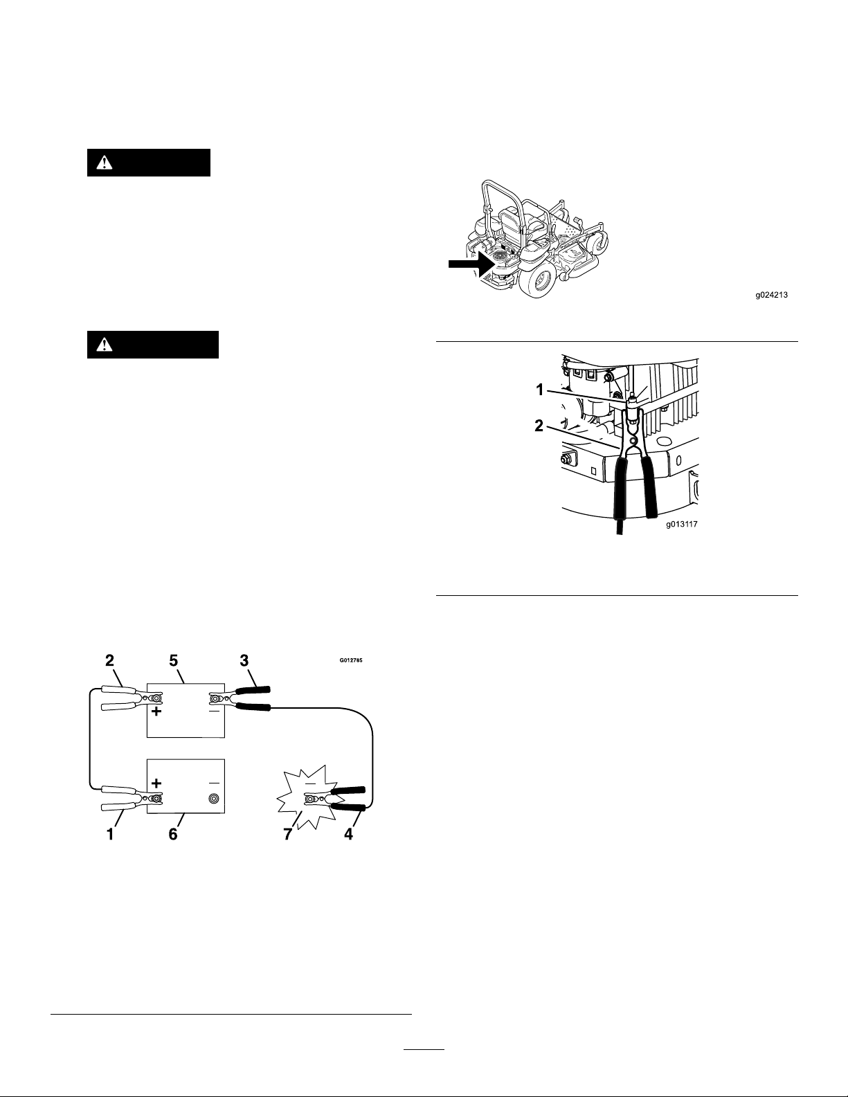
2.Makesuretheboosterbatteryisagoodandfully
g024213
g0131 17
1
2
chargedleadacidbatteryat12.6voltsorgreater.Use
properlysizedjumpercableswithshortlengthsto
reducevoltagedropbetweensystems.Makesure
thecablesarecolorcodedorlabeledforthecorrect
polarity.
CAUTION
Connectingthejumpercablesincorrectly
(wrongpolarity)canimmediatelydamagethe
EFIsystem.
Becertainofbatteryterminalpolarityand
jumpercablepolaritywhenhookingup
batteries.
WARNING
Batteriescontainacidandproduceexplosive
gases.
•Shieldtheeyesandfacefromthebatteries
atalltimes.
4.Connecttheotherendofthepositivecabletothe
positiveterminaloftheboosterbattery.
5.Connecttheblacknegative(–)cabletotheother
terminal(negative)oftheboosterbattery.
6.Makethenalconnectionontheengineblockof
thestalledvehicle(
not
tothenegativebatterypost)
awayfromthebatteryandstandback(Figure61).
Figure60
•Donotleanoverthebatteries.
Note:Besuretheventcapsaretightandlevel.Place
adampcloth,ifavailable,overanyventcapsonboth
batteries.Besurethevehiclesdonottouchandthat
bothelectricalsystemsareoffandatthesamerated
systemvoltage.Theseinstructionsarefornegative
groundsystemsonly .
3.Connectthepositive(+)cabletothepositive(+)
terminalofthedischargedbatterythatiswiredtothe
starterorsolenoidasshowninFigure59.
Figure59
Figure61
1.Engineblock
2.Negative(–)cable
7.Startthevehicleandremovethecablesinthe
reverseorderofconnection(theengineblock(black)
connectionisthersttodisconnect).
1.Positive(+)cableon
dischargedbattery
2.Positive(+)cableon
boosterbattery
3.Negative(–)cableonthe
boosterbattery
4.Negative(–)cableonthe
engineblock
5.Boosterbattery
6.Dischargedbattery
7.Engineblock
42
Page 43
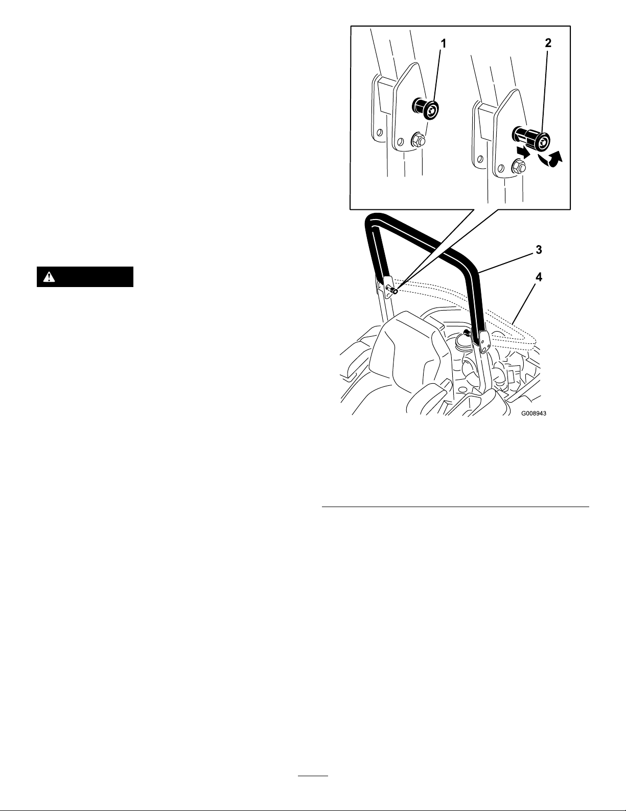
DriveSystem
Maintenance
CheckingtheSeatBelt
ServiceInterval:Beforeeachuseordaily
Visuallyinspectseatbeltforwear,cuts,andproperoperation
ofretractorandbuckle.Replacebeforeoperatingifdamaged.
CheckingtheRollover ProtectionSystem(ROPS) Knobs
ServiceInterval:Beforeeachuseordaily
WARNING
Toavoidinjuryordeathfromrollover:keeptheroll
barinthefullyraisedlockedpositionandusethe
seatbelt.
Ensurethattherearpartoftheseatissecuredwith
theseatlatch.
Checkthatboththemountinghardwareandtheknobsare
ingoodworkingcondition.Makesuretheknobsarefully
engagedwiththeROPSinthefullyraisedposition.The
upperhoopoftherollbarmayneedtobepushedforwardor
pulledrearwardtogetbothknobsfullyengaged.
Figure62
1.ROPSknob(locked
position)
2.PullROPSknoboutand
rotate90degreesto
changerollbarposition
3.Rollbarintheupright
position
4.Rollbarinthefolded
position
AdjustingtheTracking
1.Disengagetheblade-controlswitch(PTO).
2.Drivetoanopenatarea,movethemotion-control
leverstotheneutral-lockedposition.
3.Movethethrottlemidwaybetweenfastandslow.
4.Movebothmotion-controlleversallthewayforward
untiltheybothhitthestopsintheT-slot.
5.Checkwhichwaythemachinetracks.
6.Ifittrackstotheright,loosentheboltsandadjust
theleftstopplaterearwardontheleftT-slotuntilthe
machinetracksstraight(Figure63).
7.Ifittrackstotheleft,loosentheboltsandadjustthe
rightstopplaterearwardontherightT-slotuntilthe
machinetracksstraight(Figure63).
8.Tightenthestopplate(Figure63).
43
Page 44
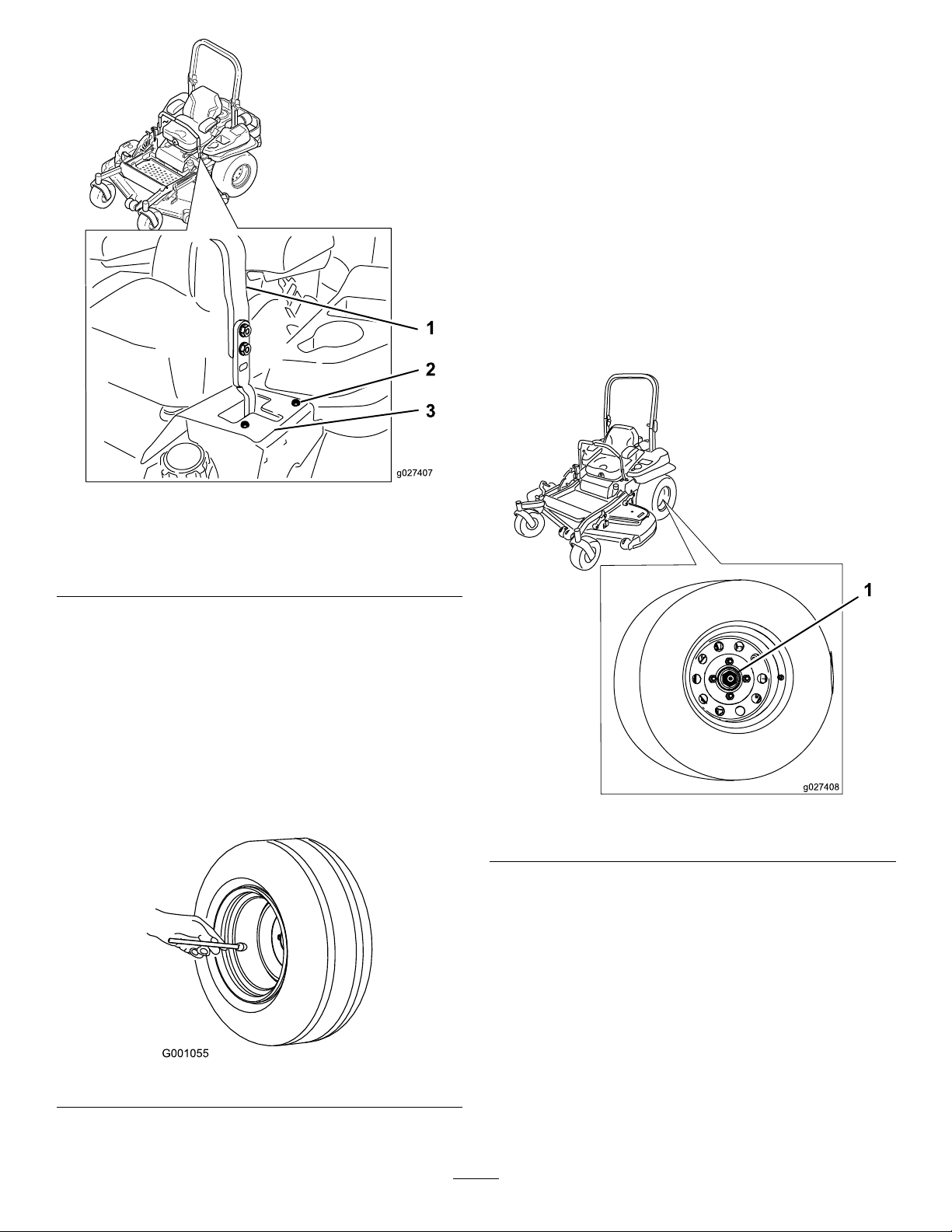
g027407
Figure63
g027408
Leftcontrollevershown
CheckingtheWheelLugNuts
ServiceInterval:Aftertherst100hours
Every500hours
Checkandtorquethewheellugnutsto122-129N-m(90-95
ft-lb).
CheckingtheWheelHub SlottedNut
ServiceInterval:Aftertherst100hours
Every500hours
Checkandensurethatthetorqueoftheslottednutis286to
352N-m(211to260ft-lb).
Note:Donotuseanti-seizeonwheelhub.
1.Controllever3.Stopplate
2.Bolt
CheckingtheTirePressure
ServiceInterval:Every50hours/Monthly(whichever
comesrst)
Maintaintheairpressureinthereartiresat90kPa(13psi).
Uneventirepressurecancauseunevencut.Checkthetires
whentheyarecoldtogetthemostaccuratepressurereading.
Note:Thefronttiresaresemi-pneumatictiresanddonot
requireairpressuremaintenance.
Figure64
Figure65
1.Slottednut
AdjustingtheCaster-Pivot Bearing
ServiceInterval:Every500hours/Yearly(whichevercomes
rst)
1.Disengagetheblade-controlswitch(PTO),movethe
motion-controlleverstotheneutral-lockedposition
andsettheparkingbrake.
2.Stoptheengine,removethekey,andwaitforallmoving
partstostopbeforeleavingtheoperatingposition.
3.Removethedustcapfromcasterandtightenlocknut
(Figure66).
44
Page 45
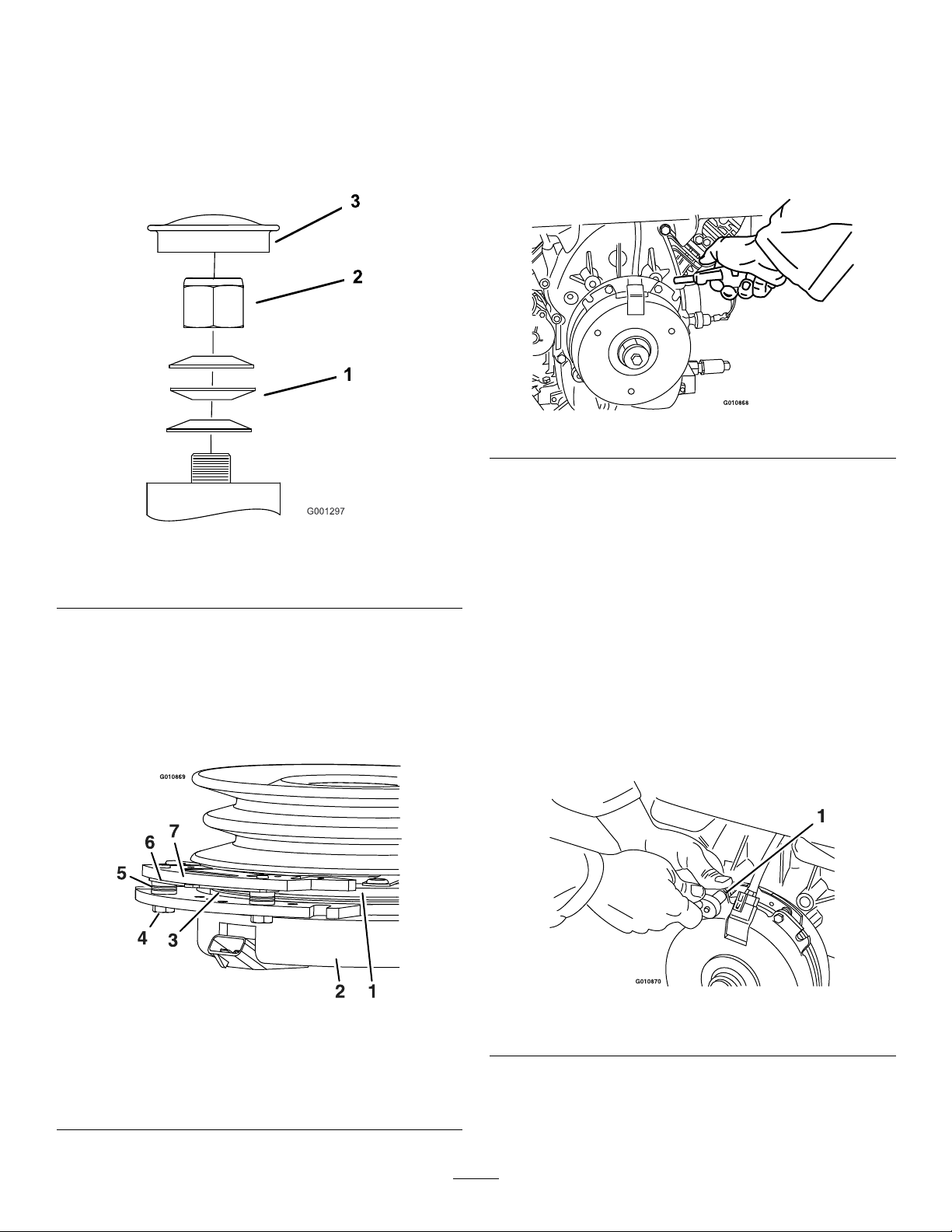
4.Tightenthelocknutuntilthespringwashersareatand
thenbackoffa1/4turntoproperlysetthepre-loadon
thebearings(Figure66).
Important:Makesurethespringwashersare
installedcorrectlyasshowninFigure66.
5.Installthedustcap(Figure66).
RemovingtheClutchShim
1.Stoptheengine,waitforallmovingpartstostop,and
removethekey.Engagetheparkingbrake.Allow
themachinetocoolcompletelybeforestartingthese
instructions.
2.Usinganaircompressor,blowoutanydebrisfrom
underthebrakepoleandaroundthebrakespacers.
Figure68
3.Checktheconditionofthewireharnessleads,
connectors,andterminals.Cleanorrepairasnecessary.
Figure66
1.Springwashers
2.Locknut
3.Dustcap
UsingtheClutchShim
Somelatermodelyearunitshavebeenbuiltwithclutchesthat
containabrakeshim.Whentheclutchbrakehasworntothe
pointwheretheclutchnolongerengagesconsistently,the
shimcanberemovedtoextendtheclutchlife.
4.Verifythat12Vispresentattheclutchconnector
whenthePTOswitchisengaged.
5.Measurethegapbetweentherotorandarmature.If
thegapisgreaterthan1mm(0.04inch),proceedwith
thefollowingsteps:
A.Loosenbothbrakemountingboltsone-halfto
onefullturnasshownbelow .
Note:Donotremovethebrakepolefromthe
eldshell/armature.Thebrakepolehasworn
tomatchthearmatureandneedstocontinueto
matchaftertheshimisremovedtoensureproper
braketorque.
Figure67
1.Armature5.Brakespacer
2.Fieldshell6.Re-gapshim
3.Rotor7.Brakepole
4.Brakemountingbolt
Figure69
1.Brakemountingbolt
B.Usingneedlenosepliers,orbyhand,takehold
ofthetabandremovetheshim(Donotdiscard
theshimuntilproperclutchfunctionhasbeen
conrmed).
45
Page 46
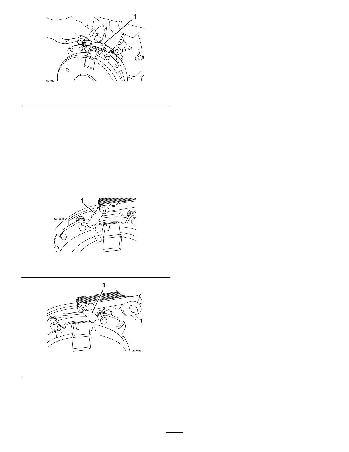
F.Performthefollowingsafetycheck:
i.Sitontheseatandstarttheengine.
ii.MakesurethebladesDonotengagewith
thePTOswitch“off”andtheclutch
disengaged.
Iftheclutchdoesnotdisengage,reinstall
theshimandreferenceTroubleshooting
(page65).
Figure70
1.Shim
C.Usingapneumaticline,blowoutanydebris
fromunderthebrakepoleandaroundthebrake
spacers.
D.Re-torqueeachbolt(M6x1)to13N-m(10ft-lb)
+/-0.7N-m(0.5ft-lb).
E.Usinga0.010inchthickfeelergauge,verifythat
agapispresentbetweentherotorandarmature
faceonbothsidesofthebrakepoleasshown.
(Duetothewaytherotorandarmaturefaces
wear(peaksandvalleys)itissometimesdifcult
tomeasurethetruegap.)
iii.EngageanddisengagethePTOswitch
tenconsecutivetimestoensuretheclutch
isfunctioningproperly.Iftheclutch
doesnotengageproperly ,reference
Troubleshooting(page65).
1.Feelergauge
1.Feelergauge
Figure71
Figure72
•Ifthegapislessthan0.010inch,thenreinstall
theshimandreferenceTroubleshooting(page
65).
•Ifthegapissufcient,proceedtothesafety
checkinstepF.
46
Page 47
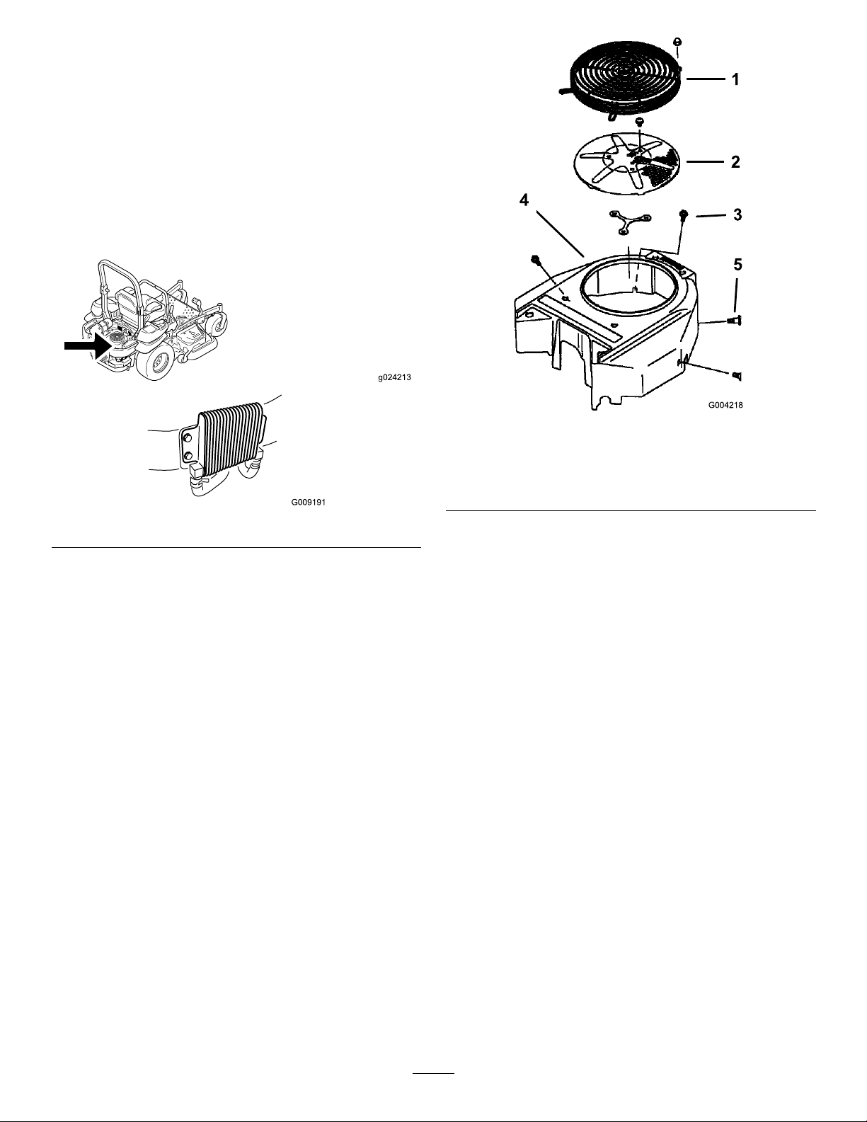
CoolingSystem
g024213
Maintenance
CleaningtheEngineScreen andEngine-OilCooler
ServiceInterval:Beforeeachuseordaily
Removeanybuild-upofgrass,dirtorotherdebrisfromthe
oilcooler(Figure73).
Figure74
1.Engineguard4.Fanhousing
2.Engineair-intakescreen
3.Bolt
5.Screw
Figure73
Beforeeachuseremoveanybuild-upofgrass,dirtor
otherdebrisfromtheenginescreen.Thiswillhelpinsure
adequatecoolingandcorrectenginespeedandwillreduce
thepossibilityofoverheatingandmechanicaldamagetothe
engine(Figure74).
CleaningtheEngineCooling FinsandShrouds
ServiceInterval:Every100hours/Yearly(whichevercomes
rst)
1.DisengagethePTOandsettheparkingbrake.
2.Stoptheengine,removethekey,andwaitforallmoving
partstostopbeforeleavingtheoperatingposition.
3.Removetheair-intakescreen,recoilstarterandfan
housing(Figure74).
4.Cleanthedebrisandgrassfromtheengineparts.
5.Installair-intakescreen,recoilstarterandfanhousing
(Figure74).
CheckingandCleaningthe HydraulicUnitShrouds
ServiceInterval:Beforeeachuseordaily
1.DisengagethePTOandsettheparkingbrake.
2.Stoptheengine,removethekey,andwaitforallmoving
partstostopbeforeleavingtheoperatingposition.
3.Raisetheseat.
4.Cleanthedebrisandgrassfromthehydraulicunit
shrouds(Figure75).
5.Lowertheseat.
47
Page 48
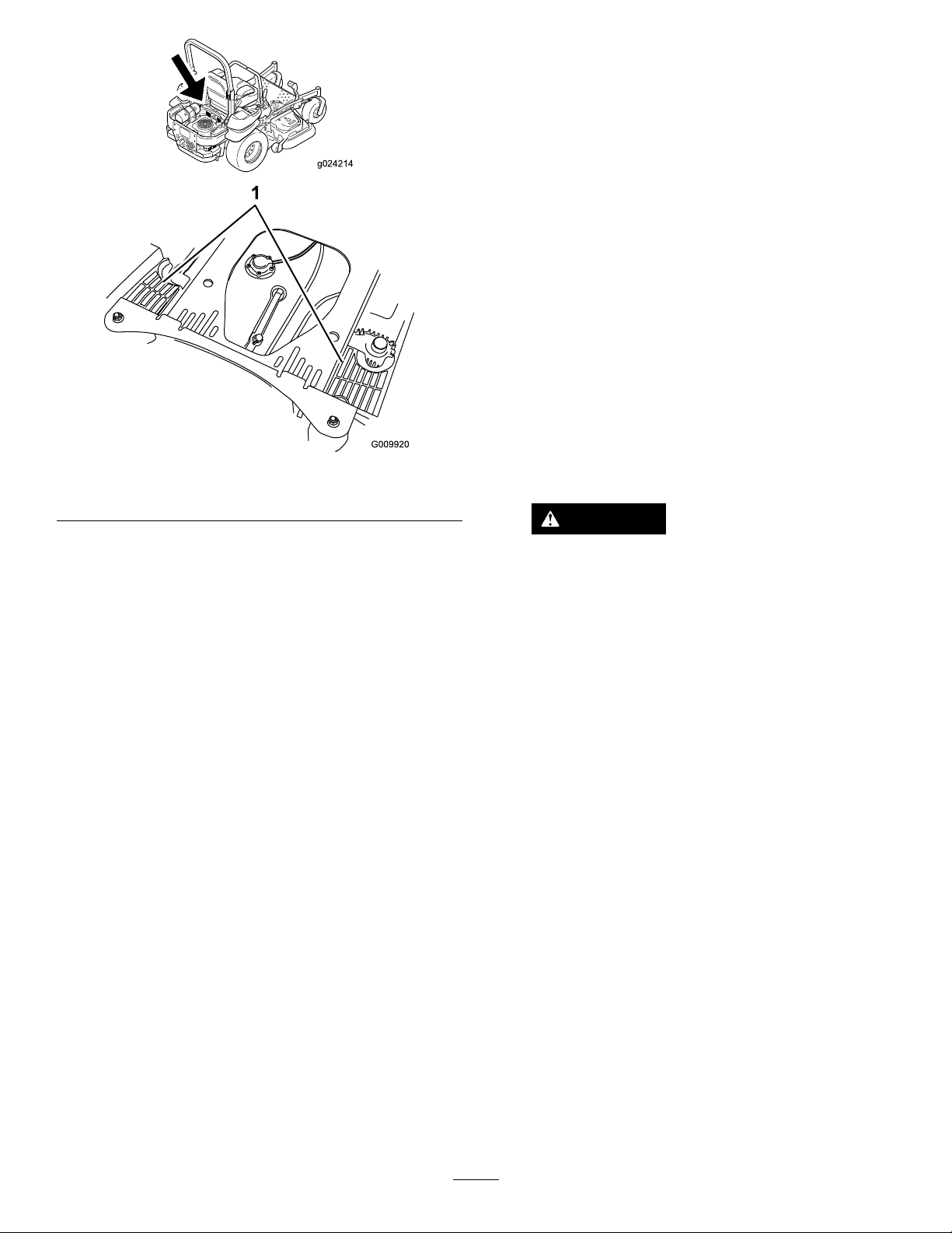
g024214
BrakeMaintenance
AdjustingtheParkingBrake
ServiceInterval:Aftertherst100hours
Every500hoursthereafter
Checktomakesurethebrakeisadjustedproperlybefore
adjusting.
Note:Thisproceduremustbefollowedaftertherst100
hoursorwhenabrakecomponenthasbeenremovedor
replaced.
1.Drivethemachineontoalevelsurface.
2.Disengagetheblade-controlswitch(PTO),movethe
motion-controlleverstotheneutral-lockedposition
andengagetheparkingbrake.
3.Stoptheengine,waitforallmovingpartstostop,and
removethekey.
1.Hydraulicunitshrouds
Figure75
4.Raisethebackofthemachineupandsupportthe
machinewithjackstands.
DANGER
Mechanicalorhydraulicjacksmayfailto
supportmachineandcauseaseriousinjury.
•Usejackstandwhensupportingmachine.
•Donotusehydraulicjacks.
5.Removethereartiresfromthemachine.
6.Removeanydebrisfromthebrakearea.
7.Rotatethedrivewheelreleasehandletothereleased
position.RefertoUsingtheDrive-WheelRelease
Valves(page25).
8.Checktoseeifthereisavisiblegapbetweenthe
L-bracketandthelinkagestop(Figure76).
48
Page 49
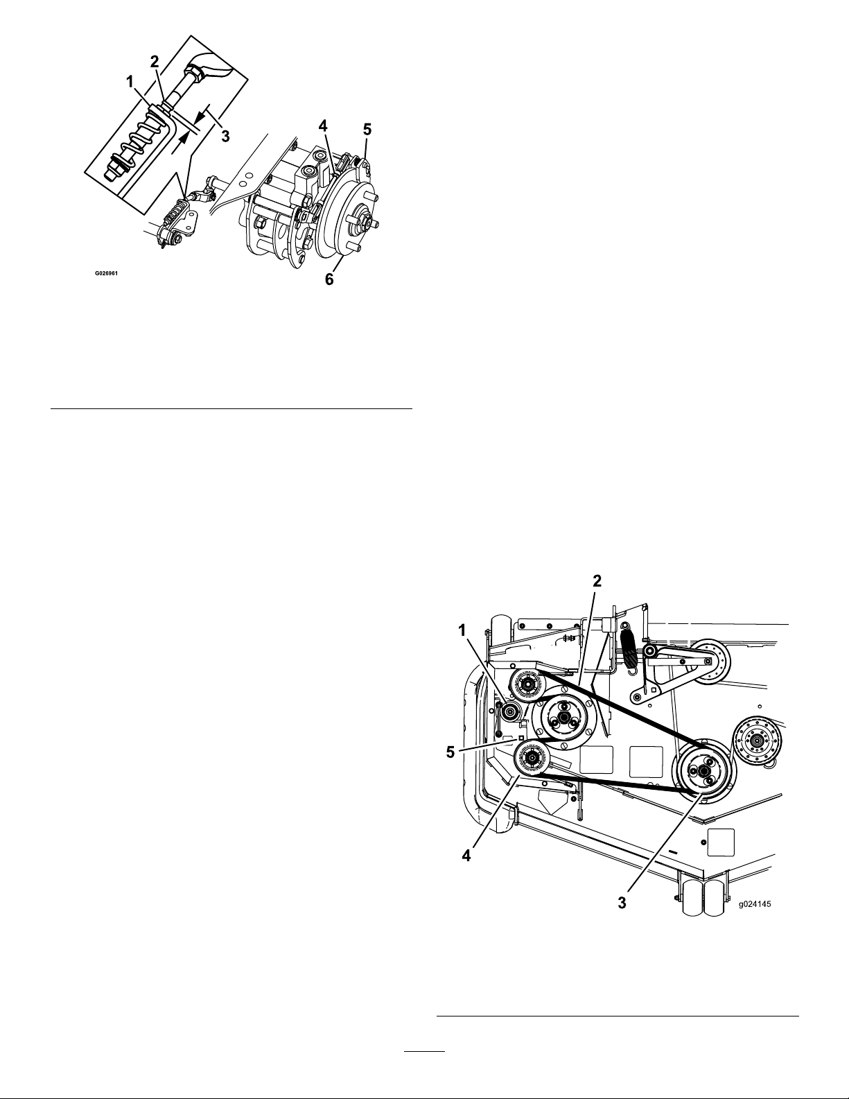
Figure76
LeftSideShown
1.L-bracket4.Rearlinkageassembly
2.Linkagestop
3.Gap
5.Caliper
6.Wheelhub
BeltMaintenance
InspectingtheBelts
ServiceInterval:Every50hours
Checkthebeltsforsquealingwhenthebeltisrotating,blades
slippingwhencuttinggrass,frayedbeltedges,burnmarksand
cracksaresignsofawornmowerbelt.Replacethemower
beltifanyoftheseconditionsareevident.
Replacingthe Counter-RotatingBelt
Squealingwhenthebeltisrotating,bladesslippingwhen
cuttinggrass,frayedbeltedges,burnmarksandcracksare
signsofawornmowerbelt.Replacethebeltifanyofthese
conditionsareevident.
1.DisengagethePTO ,movethemotion-controlleversto
theneutral-lockedpositionandsettheparkingbrake.
9.Disengagetheparkingbrake,thelevershouldbein
thedownposition.
10.Turnthewheelhubbyhandinbothdirectionsrelative
tothecaliper;thewheelhubshouldmovefreely
betweenthecaliper.
11.Ifagapisneededorthewheelhubdoesnotmove
freely:
A.Disengagetheparkingbrake.
B.Disconnectandne-tunetherearlinkage
assembly:
•Shortenthelinktocreateagap.
•Lengthenthelinktoallowwheelhub
movement.
C.Reconnecttherearlinkageassembly.
12.Engagetheparkingbrakeandcheckthegap.
13.Repeatsteps9through13untilavisiblegapisachieved
andthewheelhubrotatesfreely .
14.Repeatthisprocedureforthebrakeontheopposite
side.
2.Stoptheengine,removethekey,andwaitforallmoving
partstostopbeforeleavingtheoperatingposition.
3.Lowerthemowertothe76mm(3inches)heightofcut.
4.Lifttheoorpanuptogainaccesstothecenterpulley .
5.Removetheplasticbeltcover(Figure78).
6.Removethe3boltsholdingthemetalbeltcoverin
placeandremovethemetalbeltcover.
15.Rotatethedrivewheelreleasehandletotheoperating
position.RefertoUsingtheDrive-WheelRelease
Valves(page25).
16.Installthereartiresandtorquethelugnuts.Referto
CheckingtheWheelLugNuts(page44)
17.Removethejackstands.
Figure77
1.Idlerspring4.Idlerpulley
2.Counter-rotatingbelt5.Squareholeforratchet
3.Doublepulley
49
Page 50
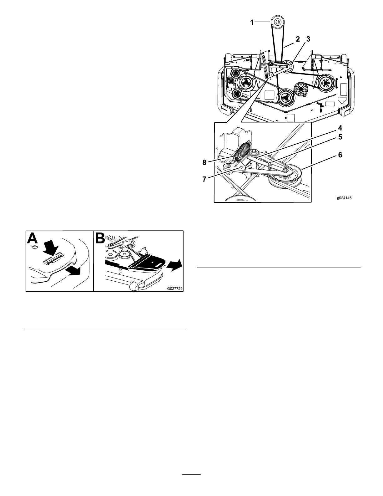
7.Usearatchetinthesquareholeintheidlerarmto
removetensionontheidlerspring(Figure77).
8.Removethebeltfromthemowerdeckpulley(Figure
77).
9.Removethebeltfromtheremainingpulleys(Figure
77).
10.Usingtheratchetinthesquarehole,installthenew
beltaroundthemowerpulleysandtheidlerpulleys
(Figure77).
ReplacingtheMowerDeck Belt
Squealingwhenthebeltisrotating,bladesslippingwhen
cuttinggrass,frayedbeltedges,burnmarksandcracksare
signsofawornmowerbelt.Replacethebeltifanyofthese
conditionsareevident.
1.DisengagethePTO ,movethemotion-controlleversto
theneutral-lockedpositionandsettheparkingbrake.
2.Stoptheengine,removethekey,andwaitforallmoving
partstostopbeforeleavingtheoperatingposition.
3.Lowerthemowertothe76mm(3inches)heightofcut.
4.Removethebeltcovers(Figure78).
Figure79
1.Clutchpulley
2.Mowerbelt
3.Springloadedidlerpulley7.Squareholeintheidler
4.Ensurebelt-guidetabhits
againstthepivothub
5.Beltguide
6.Spring-loadedidlerpulley
armfortheratchet
8.Spring
Figure78
Leftsideshown
1.Pushtabdown2.Removebeltcover
5.Removethecounter-rotatingbelt;refertoReplacing
theCounter-RotatingBelt(page49).
6.Usearatchetinthesquareholeintheidlerarmto
removetensionontheidlerspring(Figure79).
7.Removethebeltfromthemowerdeckpulley.
8.Liftuponthebelt-guidetabandremovetheexisting
belt(Figure79).
9.Installthenewbeltaroundthemowerpulleysandthe
clutchpulleyundertheengine(Figure79).
10.Rotateandensurethebelt-guidetabhitsagainstthe
pivothubFigure79.
11.Usingtheratchetinthesquarehole,installtheidler
spring(Figure79).
Makesurethespringendsareseatedintheanchor
grooves.
12.Installthebeltcovers(Figure80).
50
Page 51
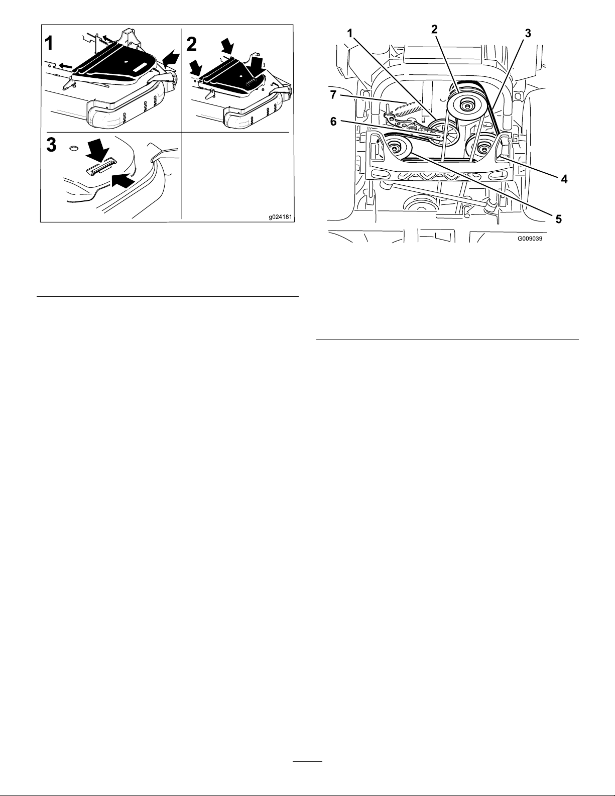
Figure80
1.Positionthebeltcover3.Ensurethetabisunder
themetalcatch
2.Slidebeltcoverunderthe
sidecatches
ReplacingtheHydraulic Pump-DriveBelt
1.DisengagethePTOandsettheparkingbrake.
2.Stoptheengine,removethekey,andwaitforallmoving
partstostopbeforeleavingtheoperatingposition.
3.Removemowerbelt.RefertoReplacingtheMower
DeckBelt(page50).
4.Raisethemachineandsupportitwithjackstands
(Figure81).
Figure81
1.Idlerpulley
2.Clutchpulley6.Squareholeinidlerarm
3.Pump-drivebelt7.Idlerspring
4.Righthydraulicpump
pulley
5.Lefthydraulicpumppulley
5.Usearatchetinthesquareholeintheidlerarmto
removetheidlerspring(Figure81).
6.Unhooktheidlerspringfromtheframe(Figure81).
7.Removethebeltfromthehydraulicunitdrivepulleys
andtheenginepulley
8.Installthenewbeltaroundenginepulleyandthetwo
drivepulleys.
9.Usingaratchetinthesquareholeintheidlerarm,
installtheidlerspringtotheframe(Figure81).
10.Installthemowerbelt.RefertoReplacingtheMower
DeckBelt(page50).
51
Page 52
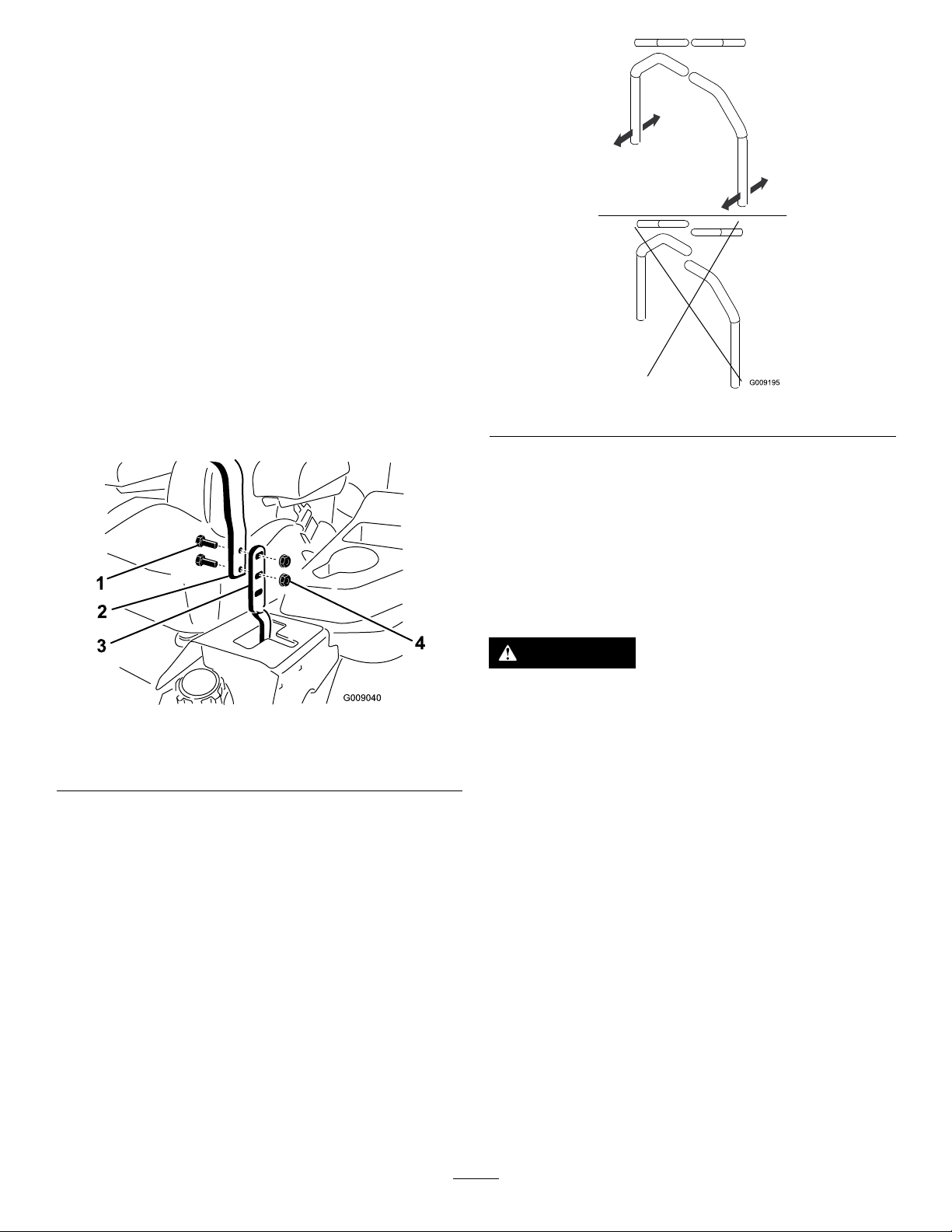
ControlsSystem
Maintenance
AdjustingtheControlHandle Position
Therearetwoheightpositionsforthecontrollevers;highand
low .Removetheboltstoadjusttheheightfortheoperator.
1.DisengagethePTO ,movethemotion-controlleversto
theneutral-lockedposition,andsettheparkingbrake.
2.Stoptheengine,removethekey,andwaitforallmoving
partstostopbeforeleavingtheoperatingposition.
3.Loosentheboltsandangenutsinstalledinthelevers
(Figure82).
4.Aligntheleversfronttorearpositionbybringthe
leverstogethertotheneutralpositionandslidethem
untiltheyarealigned,thentightenthebolts(Figure83).
Figure82
1.Bolt
2.Handle4.Nut
3.Controllever
Figure83
AdjustingtheMotion-Control Linkage
Locatedoneithersideofthefueltank,belowtheseatare
thepumpcontrollinkages.Rotatingthepumplinkagewitha
1/2inchwrenchallowsnetuningadjustmentssothatthe
machinedoesnotmoveinneutral.Anyadjustmentsaremade
forneutralpositioningonly.
WARNING
Enginemustberunninganddrivewheelsmust
beturningsomotioncontroladjustmentcanbe
performed.Contactwithmovingpartsorhot
surfacesmaycausepersonalinjury.
Keepngers,hands,andclothingclearofrotating
componentsandhotsurfaces.
1.Priortostartingtheengine,pushthedeckliftpedal
andremovetheheightofcutpin.Lowerdecktothe
ground.
2.Raisetherearofmachineupandsupportwithjack
stands(orequivalentsupport)justhighenoughto
allowdrivewheelstoturnfreely.
3.Removetheelectricalconnectionfromtheseatsafety
switch,locatedunderthebottomcushionoftheseat.
Theswitchisapartoftheseatassembly .
4.Temporarilyinstallajumperwireacrosstheterminals
intheconnectorofthemainwiringharness.
5.Startengine.Ensurethebrakeisengagedand
motion-controlleversouttostartengine.The
operatordoesnothavetobeintheseatbecause
ofthejumperwirebeingused.Runengineatfull
throttleandreleasebrake.
52
Page 53
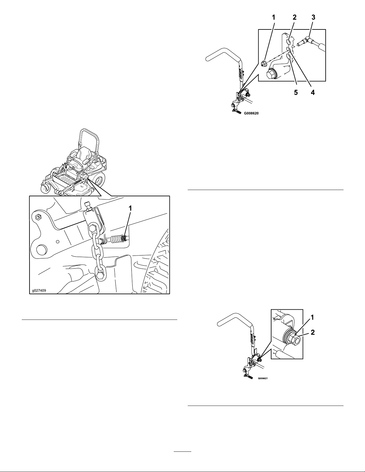
6.Runtheunitatleast5minuteswiththedriveleversat
g027409
fullforwardspeedtobringhydraulicoiluptooperating
temperature.
Note:Themotion-controlleverneedstobeinneutral
whilemakinganynecessaryadjustments.
7.Bringthemotion-controlleversintotheneutral
position.Adjustpumpcontrolrodlengthsbyrotating
thedoublenutsontherodintheappropriatedirection
untilthewheelsslightlycreepinreverse(Figure84).
Movethemotion-controlleverstothereverseposition
andwhileapplyingslightpressuretotheleverallow
thereverseindicatorspringstobringtheleversback
toneutral.Thewheelsmuststopturningorslightly
creepinreverse.
Figure85
RHMotionControlShown
1.T orquethelocknutto22.6N-m(16.7ft-lb).Boltmust
protrudepastendoflocknutaftertorque.
2.Mostresistance(rmestfeel)
3.Damper
4.Mediumresistance(mediumfeel)
5.Leastresistance(softestfeel)
Figure84
1.Doublenuts
8.Shutoffunit.Removejumperwirefromwireharness
andplugconnectorintoseatswitch.
9.Removethejackstands.
10.Raisethedeckandre-installtheheightofcutpin.
11.Checkthatthemachinedoesnotcreepinneutralwith
theparkbrakesdisengaged.
AdjustingtheMotion-Control Neutral-LockPivot
Theangednutcanbeadjustedtoobtainamoredesired
motion-controlleverresistancewhenmovingittothe
neutral-lockposition.SeeFigure86foradjustmentoptions.
1.Loosenthejamnut.
2.Tightenorloosentheangednuttothedesiredfeel.
Formoreresistance,tightentheangednut.
Forlessresistance,loosentheangednut
3.Tightenjamnut.
Figure86
AdjustingtheMotion-Control Damper
Thetopdampermountingboltcanbeadjustedtoobtaina
moredesiredmotion-controlleverresistance.SeeFigure85
formountingoptions.
1.Flangednut2.Jamnut
53
Page 54
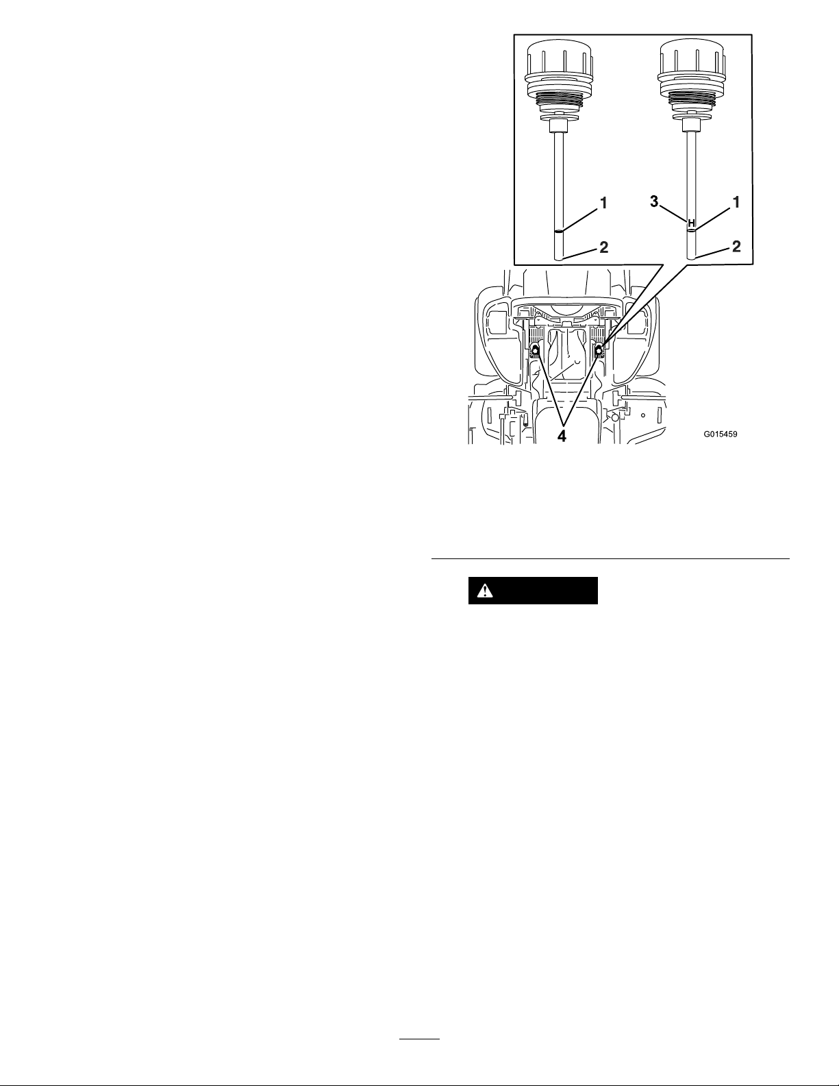
HydraulicSystem
G015459
H
3
4
Maintenance
ServicingtheHydraulic System
HydraulicOilType:Toro
orMobil
Important:Useoilspecied.Otheruidscouldcause
systemdamage.
EachHydraulicSystemOilCapacity:1.5L(52oz)per
sidewithlterchange
®
115W -50.
®
HYPR-OIL
™
500hydraulicoil
CheckingtheHydraulicOil
ServiceInterval:Every50hours—Checkthehydraulicoil
level.
1.Positionthemachineonalevelsurface.
2.DisengagethePTO ,movethemotion-controlleversto
theneutral-lockedpositionandsettheparkingbrake.
3.Stoptheengine,removethekey,andwaitforallmoving
partstostopbeforeleavingtheoperatingposition.
4.Allowtheengineandhydraulicsystemtocoolforten
minutes.
Note:Theoillevelonthedipstickwillbeincorrect
whentheoilischeckedandtheunitishot.
5.Movetheseatforward.
6.Cleantheareaaroundthedipsticksofhydraulicsystem
reservoirs(Figure87).
Figure87
Eitherdipstickwillbeusedinthemachine
1.Full3.H–meanshighlevel
2.Add4.Dipsticklocationsunder
seat
WARNING
Hydraulicoilescapingunderpressurecan
penetrateskinandcauseinjury.
7.Removeonedipstickfromthehydraulicreservoir
(Figure87).
8.Wipethedipstickoffandthreadthedipstickintothe
reservoir.
9.Removethedipstickandlookattheend(Figure87).
Iftheoillevelisattheaddmark,slowlypouronly
enoughoilintothehydraulicreservoirtoraisethelevel
tothefullorHline.
Important:Donotoverllthehydraulicunits
withoilasdamagemayoccur.Donotrunthe
machinewiththeoilbelowtheaddmark.
10.Installthedipstick.
11.Repeatprocedurefortheoppositedipstick.
•Ifhydraulicoilisinjectedintotheskinit
mustbesurgicallyremovedwithinafew
hoursbyadoctorfamiliarwiththistype
ofinjury.Gangrenemayresultifthisis
notdone.
•Keepbodyandhandsawayfrompinhole
leaksornozzlesthatejecthighpressure
hydraulicoil.
•Usecardboardorpapertondhydraulic
leaks.
•Safelyrelieveallpressureinthehydraulic
systembeforeperforminganyworkonthe
hydraulicsystem.
•Makesureallhydraulicoilhosesandlines
areingoodconditionandallhydraulic
connectionsandttingsaretightbefore
applyingpressuretohydraulicsystem.
54
Page 55
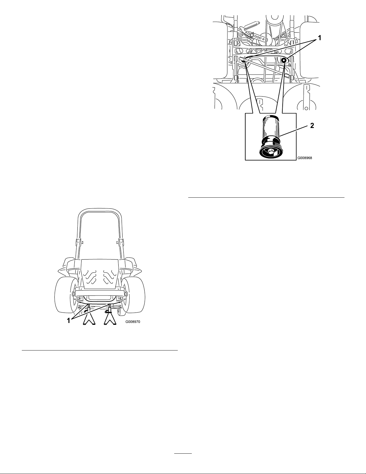
ReplacingtheHydraulicFiltersand
G008968
1
2
HydraulicOil
ServiceInterval:Aftertherst250hours—Changethe
hydraulicltersandhydraulicoilwhen
usinganytypeofoil.
Every250hours—Changethehydraulicltersand
hydraulicoilwhenusingMobil
®
1oil(moreoftenin
dirtyordustyconditions).
Every500hours—Changethehydraulicltersand
hydraulicoilwhenusingToro
®
HYPR-OIL
™
hydraulicoil(moreoftenindirtyordustyconditions).
Toreplacethehydraulicoil,theltersneedtoberemoved.
Replacebothatthesametime.Refertotheoilspecications
underServicingtheHydraulicSystem(page54)forthe
correctoil.
1.Disengagetheblade-controlswitch(PTO),movethe
motion-controlleverstotheneutral-lockedposition
andsettheparkingbrake.
2.Stoptheengine,removethekey,andwaitforallmoving
partstostopbeforeleavingtheoperatingposition.
3.Raisethemachineandsupportitwithjackstands
(Figure88).
500
Figure89
BottomViewofMachine
1.Filterlocations
2.Hydrauliclter
6.Applyathincoatofhydraulicoiltotherubbergasket
onthereplacementlter(Figure89).
7.Installthereplacementhydrauliclter.
8.Installthepump-drivebeltandthemowerbelt.
Figure88
1.Jackstands
4.Removeboththemowerbeltandthepump-drivebelt.
Thiswillpreventoilgettingonthebelts.RefertoBelt
Maintenance(page49).
5.Placeadrainpanunderthelter,removetheoldlter
andwipethesurfaceclean(Figure89).
9.Removethejackstandsandlowerthemachine(Figure
88).
10.Addoiltothehydraulicreservoirandcheckforany
leaks.
11.Cleanupanyspilledoil.
12.Starttheengineandletitrunforabouttwominutesto
purgeairfromthesystem.Stoptheengineandcheck
forleaks.
13.Checktheoillevelwhiletheoiliscold.
14.Ifrequired,addoiltothehydraulicreservoir.Donot
overll.
55
Page 56
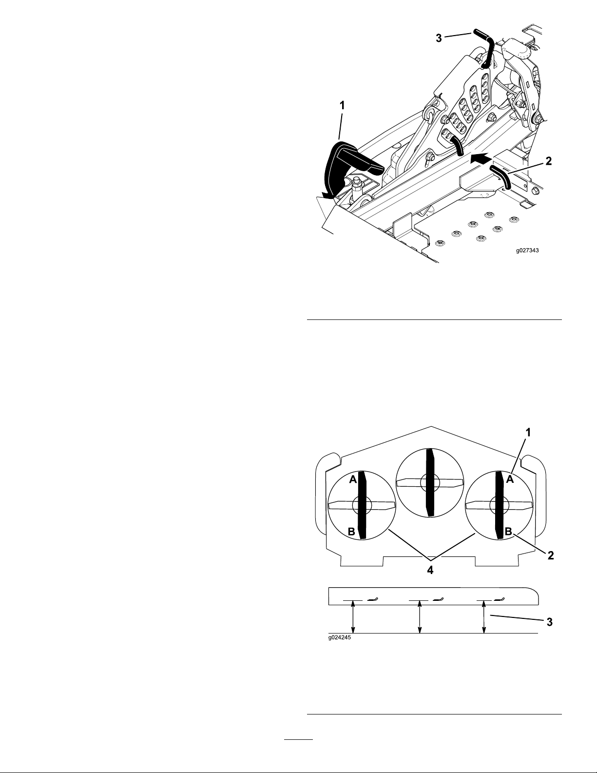
MowerDeck
4
g024245
3
2
1
Maintenance
LevelingtheMowerDeck
SettingUptheMachine
Note:Ensurethemowerdeckisleveledbeforematchingthe
height-of-cut(HOC).
1.Positionmoweronaatsurface.
2.Disengagetheblade-controlswitch(PTO),movethe
motion-controlleverstotheneutral-lockedposition
andsettheparkingbrake.
3.Stoptheengine,removethekey,andwaitforallmoving
partstostopbeforeleavingtheoperatingposition.
4.Checktirepressureofthedrivetires.Ifneeded,adjust
to90kPa(13psi).
5.Positionthemowertothe76mm(3inch)height-of-cut
position.
DeckLeveling
1.Positionthemoweronaatsurface.
2.Stopengine,waitforallmovingpartstostop,and
removekey.Engageparkingbrake.
3.Checkthetirepressureinthedrivetires.Proper
inationpressurefortiresis90kPa(13psi).Adjust
ifnecessary.
4.Positionthetransportlockinthelatchingposition.
5.Pushthedeckliftpedalallthewayforwardandthe
deckwilllatchatthe14cm(5-1/2inches)transport
position(Figure90).
Figure90
1.Deckliftpedal
2.Heightofcutpin
6.Inserttheheightadjustmentpinintothe76mm
(3inch)cuttingheightlocation.
7.Releasethetransportlockandallowthedecktolower
tothecuttingheight.
8.Onbothsidesofthedeck,measurefromthelevel
surfacetothefronttipoftheblade(PostionA).Ensure
themeasurementis7.6mm(3inches)(Figure91).
3.Transportlock
Figure91
1.76mm(3inches)atAis
correct
2.8.3cm(3-1/4inches)atB
iscorrect
56
3.Measureherefromthe
bladetiptohardsurface
4.MeasureatAandBon
bothsides
Page 57
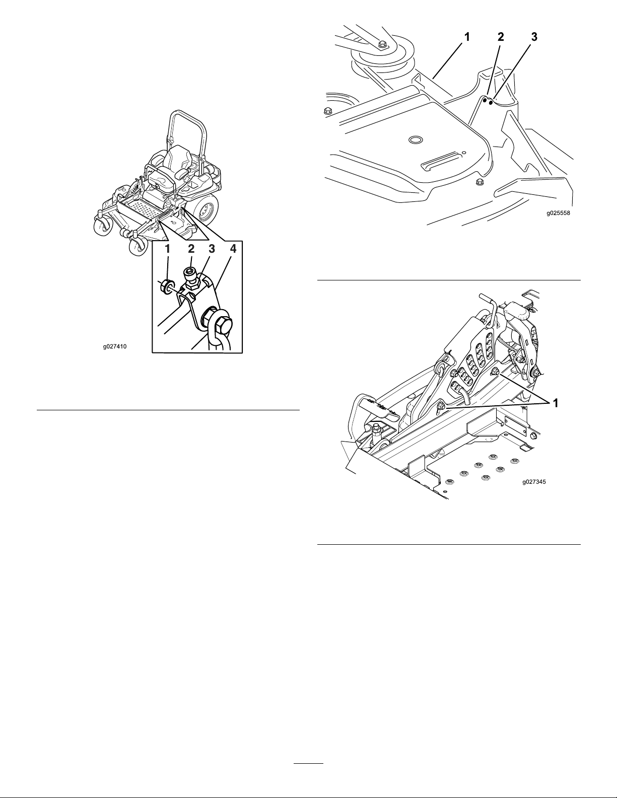
9.Ifneeded,loosenthewhizlocknutonthesideofthe
g027410
yokeandthejamnutontop.Finetunethescrew
adjusterbyturningittoget76mm(3inches)height
(seeFigure92).
Toincreasetheheight,turntheadjusterscrew
clockwise;todecrease,turncounterclockwise.
Figure93
1.Mowerdeck3.Backhole
2.Fronthole
Figure92
1.Whizlocknut3.Jamnut
2.Adjusterscrew4.Y oke
10.Ifthefrontdecklinksdonothaveenoughadjustment
toachieveaccuratecutheight,thesinglepoint
adjustmentcanbeutilizedtogainmoreadjustment.
11.Toadjustthesinglepointsystem,loosenthetwobolts
atthebottomoftheheightofcutplate.RefertoFigure
94.
Note:Themowerdeckisattachedinthebackholes
atthefactory.RefertoFigure93.Ifneeded,usethe
frontholesforfurtheradjustmentwhenlevelingthe
mowerdeck.
Figure94
1.Boltsatthebottomoftheheight-of-cutplate
12.Ifthedeckistoolow ,tightenthesinglepoint
adjustmentboltbyrotatingitclockwise.Ifthedeckis
toohigh,loosenthesinglepointadjustmentboltby
rotatingitcounterclockwise(Figure95).
Note:Loosenortightenthesinglepointadjustment
boltenoughtomovetheheight-of-cutplatemounting
boltsatleast1/3thelengthoftheavailabletravel
intheirslots.Thiswillregainsomeupanddown
adjustmentoneachofthefourdecklinks.
57
Page 58
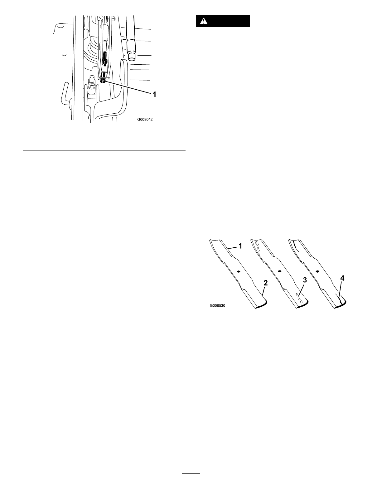
1.Singlepointadjustmentbolt
Figure95
DANGER
Awornordamagedbladecanbreak,andapiece
ofthebladecouldbethrownintotheoperator's
orbystander'sarea,resultinginseriouspersonal
injuryordeath.
•Inspectthebladeperiodicallyforwearor
damage.
•Replaceawornordamagedblade.
BeforeInspectingorServicingthe
Blades
Parkthemachineonalevelsurface,disengagethe
blade-controlswitch(PTO),andsettheparkingbrake.Turn
theignitionkeytoOff.Removethekey .
13.Tightenthetwoboltsatthebottomoftheheightofcut
plate(Figure94).Torqueto37-45N-m(27-33ft-lb).
Note:Inmostconditions,ensuretheback,bladetipis
adjusted6.4mm(1/4inch)higherthanthefront.
14.Onbothsidesofthedeck,measurefromthelevel
surfacetothebacktipoftheblade(PostionB).Ensure
themeasurementis8.3cm(3-1/4inches)(Figure91).
15.Finetunethescrewadjusterbyturningittoget8.3
mm(3-1/4inches)height(Figure92).
Toincreasetheheight,turntheadjustmentnut
clockwise;todecrease,turncounterclockwise.
16.Measureuntilallfoursidesarethecorrectheight.
Tightenallthenutsonthedeckliftarmassemblies.
ServicingtheCuttingBlades
Important:Theright-handbladeonthismowerdeck
iscounter-rotatingandusesaleft-handthreadedblade
bolt.UseFigure99forthecorrectplacementofthe
mowerblades.
Maintainsharpbladesthroughoutthecuttingseasonbecause
sharpbladescutcleanlywithouttearingorshreddingthegrass
blades.Tearingandshreddingturnsgrassbrownattheedges,
whichslowsgrowthandincreasesthechanceofdisease.
Checkthecutterbladesdailyforsharpness,andforany
wearordamage.Filedownanynicksandsharpenthe
bladesasnecessary.Ifabladeisdamagedorworn,replace
itimmediatelywithagenuineT ororeplacementblade.For
convenientsharpeningandreplacement,youmaywantto
keepextrabladesonhand.
InspectingtheBlades
ServiceInterval:Beforeeachuseordaily
1.Inspectthecuttingedges(Figure96).Iftheedges
arenotsharporhavenicks,removeandsharpenthe
blades.RefertoSharpeningtheBlades(page60).
2.Inspecttheblades,especiallythecurvedarea(Figure
96).Ifyounoticeanydamage,wear,oraslotforming
inthisarea(Figure96),immediatelyinstallanewblade.
Figure96
1.CuttingEdge3.Wear/slotForming
2.CurvedArea4.Crack
CheckingforBentBlades
1.Disengagetheblade-controlswitch(PTO),movethe
motion-controlleverstotheneutral-lockedposition
andsettheparkingbrake.
2.Stoptheengine,removethekey,andwaitforallmoving
partstostopbeforeleavingtheoperatingposition.
3.Rotatethebladesuntiltheendsfaceforwardand
backward(Figure97).Measurefromalevelsurfaceto
thecuttingedge,positionA,oftheblades(Figure97).
Notethisdimension.
58
Page 59
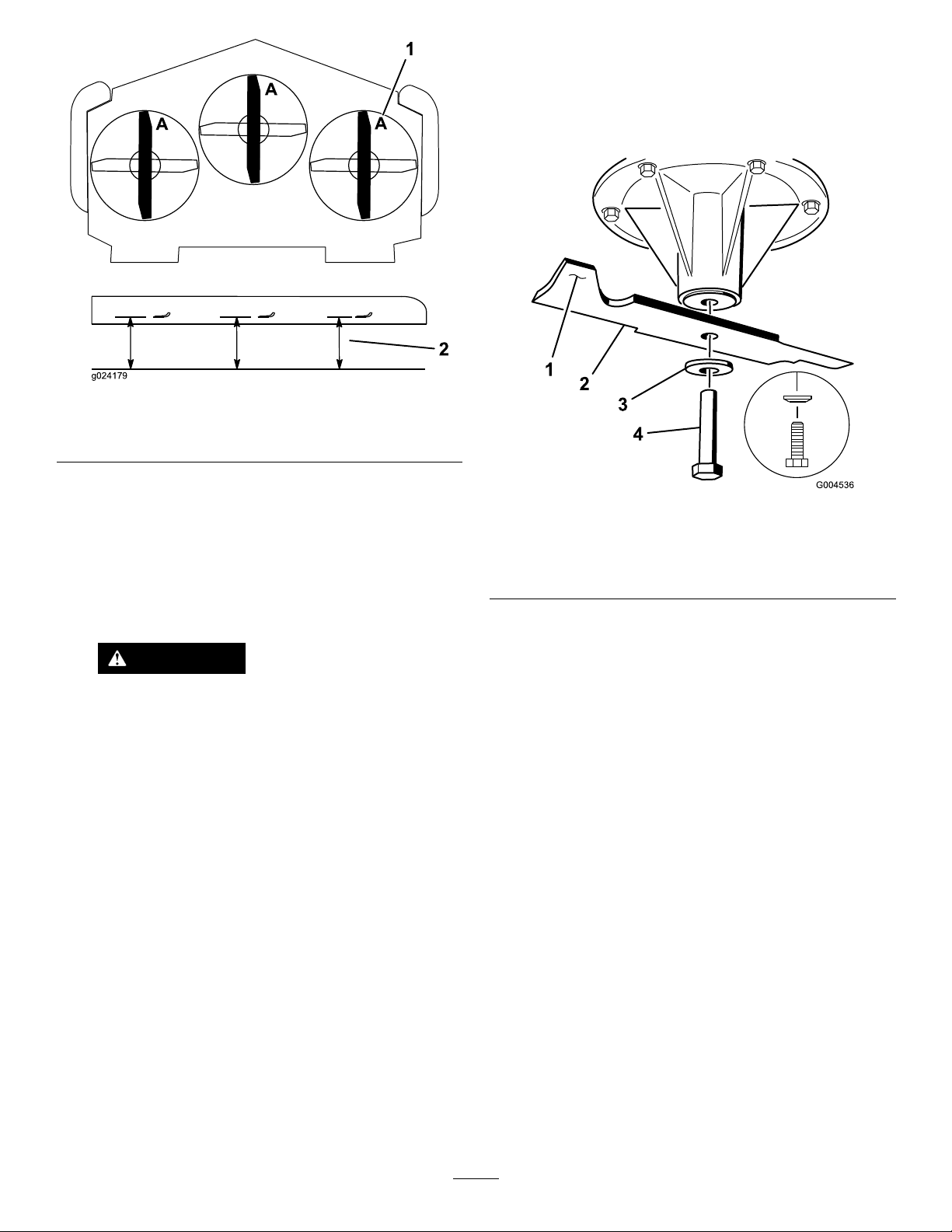
g024179
2
1
Figure97
3.Removetherightbladebolt(left-handthreadedbolt),
curvedwasher,andbladefromthespindleshaft(Figure
99).
Note:Makenoteofthetypebladeandwhereeach
bladeisinstalled.SeeFigure99forthecorrectposition.
1.Measureherefromblade
tohardsurface
2.PositionA
4.Rotatetheoppositeendsofthebladesforward.
5.Measurefromalevelsurfacetothecuttingedgeof
thebladesatthesamepositionasinstep3above.
Thedifferencebetweenthedimensionsobtainedin
steps3and4mustnotexceed3mm(1/8inch).Ifthis
dimensionexceeds3mm(1/8inch),thebladeisbent
andreplaceit;refertoRemovingtheBlades(page59)
andInstallingtheBlades(page61).
WARNING
Abladethatisbentordamagedcouldbreak
apartandcouldseriouslyinjureorkillyouor
bystanders.
•Alwaysreplacebentordamagedblade
withanewblade.
•Neverleorcreatesharpnotchesinthe
edgesorsurfacesofblade.
RemovingtheBlades
Figure98
LeftandCenterSpindleShown
1.Sailareaofblade3.Curvedwasher
2.Blade4.Bladebolt
Important:Theright-handbladeonthismowerdeck
iscounter-rotatingandusesaleft-handthreadedblade
bolt.UseFigure99forthecorrectplacementofthe
mowerblades.
Replacethebladesifasolidobjectishit,ifthebladeisout
ofbalanceorisbent.Toensureoptimumperformanceand
continuedsafetyconformanceofthemachine,usegenuine
Tororeplacementblades.Replacementbladesmadebyother
manufacturersmayresultinnon-conformancewithsafety
standards.
1.Holdthebladeendusingaragorthicklypaddedglove.
2.Removetheleftandcenterbladebolt,curvedwasher,
andbladefromthespindleshaft(Figure98).
59
Page 60
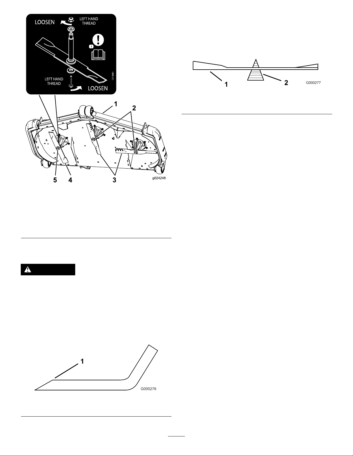
2.Checkthebalanceofthebladebyputtingitonablade
balancer(Figure101).Ifthebladestaysinahorizontal
position,thebladeisbalancedandcanbeused.Ifthe
bladeisnotbalanced,lesomemetalofftheendof
thesailareaonly(Figure102).Repeatthisprocedure
untilthebladeisbalanced.
Figure101
1.Blade2.Balancer
Figure99
Bladelocation
1.Frontofmowerdeck4.Counter-rotatingblade
2.Right-handthreadedblade
bolts
3.Regularblades
5.Left-handthreadedblade
bolt
SharpeningtheBlades
WARNING
Whensharpeningblade,piecesofbladecouldbe
thrownandcauseseriousinjury.
Wearpropereyeprotectionwhensharpeningblade.
1.Usealetosharpenthecuttingedgeatbothendsof
theblade(Figure100).Maintaintheoriginalangle.The
bladeretainsitsbalanceifthesameamountofmaterial
isremovedfrombothcuttingedges.
1.Sharpenatoriginalangle
Figure100
60
Page 61
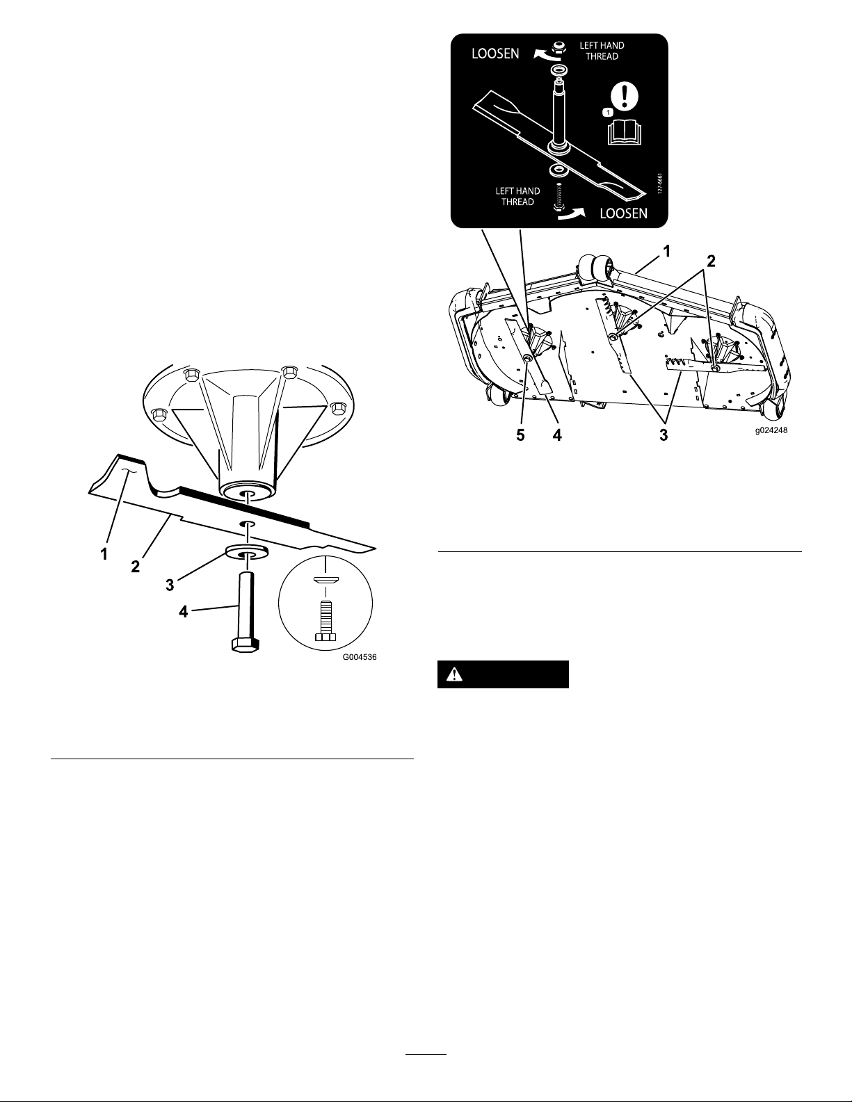
InstallingtheBlades
Important:Theright-handbladeonthismowerdeck
iscounter-rotatingandusesaleft-handthreadedblade
bolt.UseFigure103forthecorrectplacementofthe
mowerblades.
1.Installtheleftandcenterblades,curvedwashers,and
bladeboltstothespindleshafts(Figure102andFigure
103).
Note:Ensurethecurvedpartofthebladeispointing
upwardtowardtheinsideofthemowerdecktoensure
propercutting.
Note:Ensurethecurved-washerconeisinstalled
towardsthebolthead(Figure102).
2.Installtherightblade,curvedwasher,andbladebolt
(left-handthreadedbolt)tothespindleshaft(Figure
102andFigure103).
Figure102
Leftandcenterspindleshown
1.Sailareaoftheblade3.Curvedwasher
2.Blade4.Bladebolt
3.Torquethebladeboltsto115-150N-m(85-110ft-lb)
(Figure103).
Figure103
1.Frontofmowerdeck4.Counter-rotatingblade
2.Right-handthreadedblade
bolts
3.Regularblades
5.Left-handthreadedblade
bolt
RemovingtheMowerDeck
Beforeservicingorremovingthemowerdeck,lockoutthe
springloadeddeckarms.
WARNING
Deckliftarmassemblieshavestoredenergy.
Removingthedeckwithoutreleasingthestored
energycancauseseriousinjuryordeath.
Donotattempttodisassemblethedeckfromthe
frontframewithoutlockingoutthestoredenergy.
1.Stopengine,waitforallmovingpartstostop,and
removekey.Engageparkingbrake.
2.Removetheheightadjustmentpinandlowerthedeck
totheground.
3.Placetheheightadjustmentpininthe7.6cm(3inch)
cuttingheightlocation.Thislocksthedeckliftarmsin
thelowestpositionwhenthedeckisremovedandthe
storedenergyinthedeckspringisreleased.
4.Removethebeltcovers.
5.Liftuptheoorpanandinsertaratchetintothesquare
holeinthedeckidler(Figure104).
61
Page 62
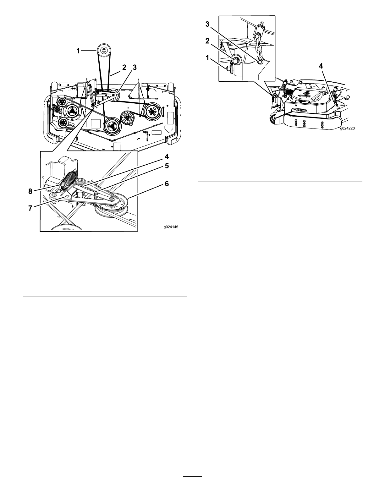
6.Rotatethemowerdeckidlerclockwise,liftuponthe
belt-guidetabandremovethemowerdeckbeltfrom
theclutch(Figure104).
Figure105
1.Rightstabilizer
2.Deckstrut(rightsideshown)
3.Removethereardeckliftattachmentshoulderboltandnut.
4.Removethefrontdeckliftattachmentshoulderboltandnut.
8.Raisethedeckstrutsandsecurethemintheup
position.Slidethedeckouttotherightsideofthe
machine.
Figure104
1.Clutchpulley
2.Mowerdeckbelt
3.Springloadedidlerpulley7.Squareholeintheidler
4.Ensurebelt-guidetabhits
againstpivothub
5.Beltguide
6.Spring-loadedidlerpulley
armfortheratchet
8.Spring
7.Removeandretainthehardwareonbothsidesofthe
deckasshowninFigure105.
62
Page 63

Cleaning
Storage
CleaningundertheMower
ServiceInterval:Beforeeachuseordaily
1.Disengagetheblade-controlswitch(PTO),movethe
motion-controlleverstotheneutral-lockedposition
andsettheparkingbrake.
2.Stoptheengine,removethekey,andwaitforallmoving
partstostopbeforeleavingtheoperatingposition.
3.Raisethemowertothetransportposition.
DisposingofWaste
Engineoil,batteries,hydraulicoil,andenginecoolantare
pollutantstotheenvironment.Disposeoftheseaccordingto
yourstateandlocalregulations.
CleaningandStorage
1.Disengagethepowertakeoff(blade-controlswitch
(PTO),settheparkingbrake,andturntheignitionkey
toOff.Removethekey.
2.Removegrassclippings,dirt,andgrimefromthe
externalpartsoftheentiremachine,especiallythe
engineandhydraulicsystem.Cleandirtandchafffrom
theoutsideoftheenginecylinderheadnsandblower
housing.
Important:Youcanwashthemachinewithmild
detergentandwater.Donotpressurewashthe
machine.Avoidexcessiveuseofwater,especially
nearthecontrolpanel,engine,hydraulicpumps,
andmotors.
3.Checkthebrake;refertoBrakeMaintenance(page48).
4.Servicetheaircleaner;refertoServicingtheAir
Cleaner(page32).
5.Greasethemachine;refertoGreasingandLubrication
(page30).
6.Changethecrankcaseoil;refertoServicingtheEngine
Oil(page34).
7.Checkthetirepressure;refertoCheckingtheTire
Pressure(page44).
8.Changethehydrauliclters;refertoServicingthe
HydraulicSystem(page54)n.
9.Chargethebattery;refertoServicingtheBattery(page
40).
10.Scrapeanyheavybuildupofgrassanddirtfromthe
undersideofthemower,thenwashthemowerwith
agardenhose.
Note:Runthemachinewiththeblade-controlswitch
(PTO)engagedandtheengineathighidlefor2to
5minutesafterwashing.
11.Checktheconditionoftheblades;refertoServicing
theCuttingBlades(page58).
12.Preparethemachineforstoragewhennon-useoccurs
over30days.Preparethemachineforstorageas
follows:
A.Addapetroleumbasedstabilizer/conditionerto
fuelinthetank.Followmixinginstructionsfrom
thestabilizermanufacturer.Donotuseanalcohol
basedstabilizer(ethanolormethanol).
Note:Afuelstabilizer/conditionerismost
effectivewhenmixedwithfreshfuelandusedat
alltimes.
B.Runtheenginetodistributeconditionedfuel
throughthefuelsystem(5minutes).
C.Stoptheengine,allowittocool,anddrainthefuel
tank;refertoServicingtheFuelTank(page39).
63
Page 64

D.Restarttheengineandrunituntilitstops.
E.Disposeoffuelproperly .Recycleasperlocal
codes.
Important:Donotstore
stabilizer/conditionedfuelover90days.
13.Checkandtightenallbolts,nuts,andscrews.Repairor
replaceanypartthatisdamaged.
14.Paintallscratchedorbaremetalsurfaces.Paintis
availablefromyourAuthorizedServiceDealer.
15.Storethemachineinaclean,drygarageorstoragearea.
Removethekeyfromtheignitionswitchandkeepit
outofreachofchildrenorotherunauthorizedusers.
Coverthemachinetoprotectitandkeepitclean.
64
Page 65

Troubleshooting
Problem
Thestarterdoesnotcrank.
Theenginedoesnotstart,startshard,or
failstokeeprunning
PossibleCauseCorrectiveAction
1.Theblade-controlswitch(PTO)is
engaged.
2.Theparkingbrakeisnoton.
3.Thedriveleversarenotinneutral-lock
position.
4.Theoperatorisnotseated.
5.Thebatteryisdead.
6.Theelectricalconnectionsare
corrodedorloose.
7.Thefuseisblown.7.Replacethefuse.
8.Therelayorswitchisdefective.8.ContactanAuthorizedServiceDealer.
1.Thefueltankisempty .1.Fillthefueltank.
2.Thefuelshutoffvalveisclosed.2.Openthefuelshutoffvalve.
3.Theoillevelinthecrankcaseislow.3.Addoiltothecrankcase.
4.Thethrottleisnotinthecorrect
position.
5.Thereisdirtinfuellter.5.Replacethefuellter.
6.Thereisdirt,water,orstalefuelinthe
fuelsystem.
7.Theaircleanerisdirty .
8.Theseatswitchisnotfunctioning
properly.
9.Theelectricalconnectionsare
corroded,looseorfaulty.
10.Therelayorswitchisdefective.10.ContactanAuthorizedServiceDealer.
11.Thesparkplugisfaulty.11.Clean,adjust,orreplacesparkplug.
12.Thesparkplugwireisnotconnected.
1.Movetheblade-controlswitch(PTO)
todisengaged.
2.Settheparkingbrake.
3.Ensurethatthedriveleversareinthe
neutral-lockposition.
4.Sitontheseat.
5.Chargethebattery.
6.Checktheelectricalconnectionsfor
goodcontact.
4.Besurethatthethrottlecontrolis
midwaybetweenthe“SLOW”and
“FAST”positions.
6.ContactanAuthorizedServiceDealer.
7.Cleanorreplacetheaircleaner
element.
8.Checktheseatswitchindicator.
Replacetheseatifneeded.
9.Checktheelectricalconnectionsfor
goodcontact.Cleantheconnector
terminalsthoroughlywithelectrical
contactcleaner,applydielectric
grease,andreconnect.
12.Checkthesparkplugwireconnection.
Theenginelosespower.
Theengineoverheats.
Themowerpullsleftorright(withlevers
fullyforward)
1.Theengineloadisexcessive.1.Reducethegroundspeed.
2.Theaircleanerisdirty .
3.Theoillevelinthecrankcaseislow.3.Addoiltothecrankcase.
4.Thecoolingnsandairpassages
abovetheengineareplugged.
5.Theventholeinthefuelcapisplugged.5.Cleanorreplacethefuelcap.
6.Thereisdirtinthefuellter.6.Replacethefuellter.
7.Thereisdirt,water ,orstalefuelisin
thefuelsystem.
1.Theengineloadisexcessive.1.Reducethegroundspeed.
2.Theoillevelinthecrankcaseislow.2.Addoiltothecrankcase.
3.Thecoolingnsandairpassages
abovetheengineareplugged.
1.Thetrackingneedsadjustment1.Adjustthetracking.
2.Thetirepressureindrivetiresnot
correct.
2.Cleantheaircleanerelement.
4.Removetheobstructionfromthe
coolingnsandairpassages.
7.ContactanAuthorizedServiceDealer.
3.Removetheobstructionfromthe
coolingnsandairpassages.
2.Adjusttirepressureinthedrivetires.
65
Page 66

Problem
PossibleCauseCorrectiveAction
Themachinedoesnotdrive.
Themachinevibratesabnormally .
Thecuttingheightisuneven.
1.Thebypassvalvesarenotclosed
tight.
2.Thepumpbeltisworn,looseorbroken.
3.Thepumpbeltisoffapulley.3.Changethebelt.
4.Theidlerspringisbrokenormissing.4.Replacethespring.
5.Thehydraulicoillevelislowortoohot.5.Addhydraulicoiltoreservoirsorletit
1.Thecuttingblade(s)is/arebentor
unbalanced.
2.Theblademountingboltisloose.2.Tightentheblademountingbolt.
3.Theenginemountingboltsareloose.3.Tightentheenginemountingbolts.
4.Theenginepulley,idlerpulley,orblade
pulleyisloose.
5.Theenginepulleyisdamaged.
6.Thebladespindleisbent.
7.Themotormountislooseorworn.
1.Theblade(s)is/arenotsharp.1.Sharpentheblade(s).
2.Thecuttingblade(s)is/arebent.2.Installnewcuttingblade(s).
3.Themowerdeckisnotlevel.
4.Theundersideofmowerisdirty.4.Cleantheundersideofthemower.
5.Thetirepressureisnotcorrect.5.Adjustthetirepressure.
6.Thebladespindleisbent.
1.Tightenthebypassvalves.
2.Changethebelt.
cooldown.
1.Installnewcuttingblade(s).
4.Tightentheappropriatepulley.
5.ContactanAuthorizedServiceDealer.
6.ContactanAuthorizedServiceDealer.
7.ContactanAuthorizedServiceDealer.
3.Levelthemowerdeckfromside-to-side
andfront-to-rear.
6.ContactanAuthorizedServiceDealer.
Thebladesdonotrotate.
Theclutchdoesnotengage.
1.Themowerdeckbeltisworn,loose
orbroken.
2.Themowerdeckbeltisoffpulley.
3.Thepump-drivebeltisworn,looseor
broken.
4.Theidlerspringisbrokenormissing.4.Replacethespring.
1.Thefuseisblown.1.Replacethefuse.Checkcoil
2.Thereislowvoltagesupplyatthe
clutch.
3.Thecoilisdamaged.3.Replacetheclutch.
4.Thereisinadequatecurrentsupply.4.Repairorreplacetheclutchlead
5.Therotor/armatureairgapistoolarge.
1.Installanewdeckbelt.
2.Installthemowerdeckpulleyand
checktheidlerpulley,idlerarm,and
springforcorrectpositionandfunction.
3.Checkthebelttensionorinstallanew
belt.
resistance,batterycharge,charging
system,andwiringconnectionsand
replaceifnecessary .
2.Checkcoilresistance,battery
charge,chargingsystem,andwiring
connectionsandreplaceifnecessary.
wireorelectricalsystem.Cleanthe
connectorcontacts.
5.Removetheshimorreplacetheclutch.
66
Page 67

Problem
PossibleCauseCorrectiveAction
MalfunctionIndicatorLight(MIL)comes
on.
1.Theengineistoohot.
2.Thereisoldgasinthegastank.2.Usenewgas.
3.Thefuelshutoffvalveisnotopen
completely.
4.Theircleanerisdirty .4.Makesurethattheaircleanerand
5.Thebatteryisnotcharged.
6.Thefuelltersareincorrectordirty.6.ContactanAuthorizedServiceDealer.
7.Connectionstosensorselectronic
controlunit(ECU)andfuelinjectors
arenotsecuredproperly.
8.Thebatteryvoltageislow.8.Ensureagood12voltbatteryisbeing
9.Thefuseisblown.9.Checkandreplaceanyblownfuses.
1.Turntheengineoffandletitcool.
3.Openthefuelshutoffvalve.
precleanerareclean.Replaceif
necessary.
5.Chargeorreplacethebattery.
7.ContactanAuthorizedServiceDealer.
usedandisfullycharged.
67
Page 68
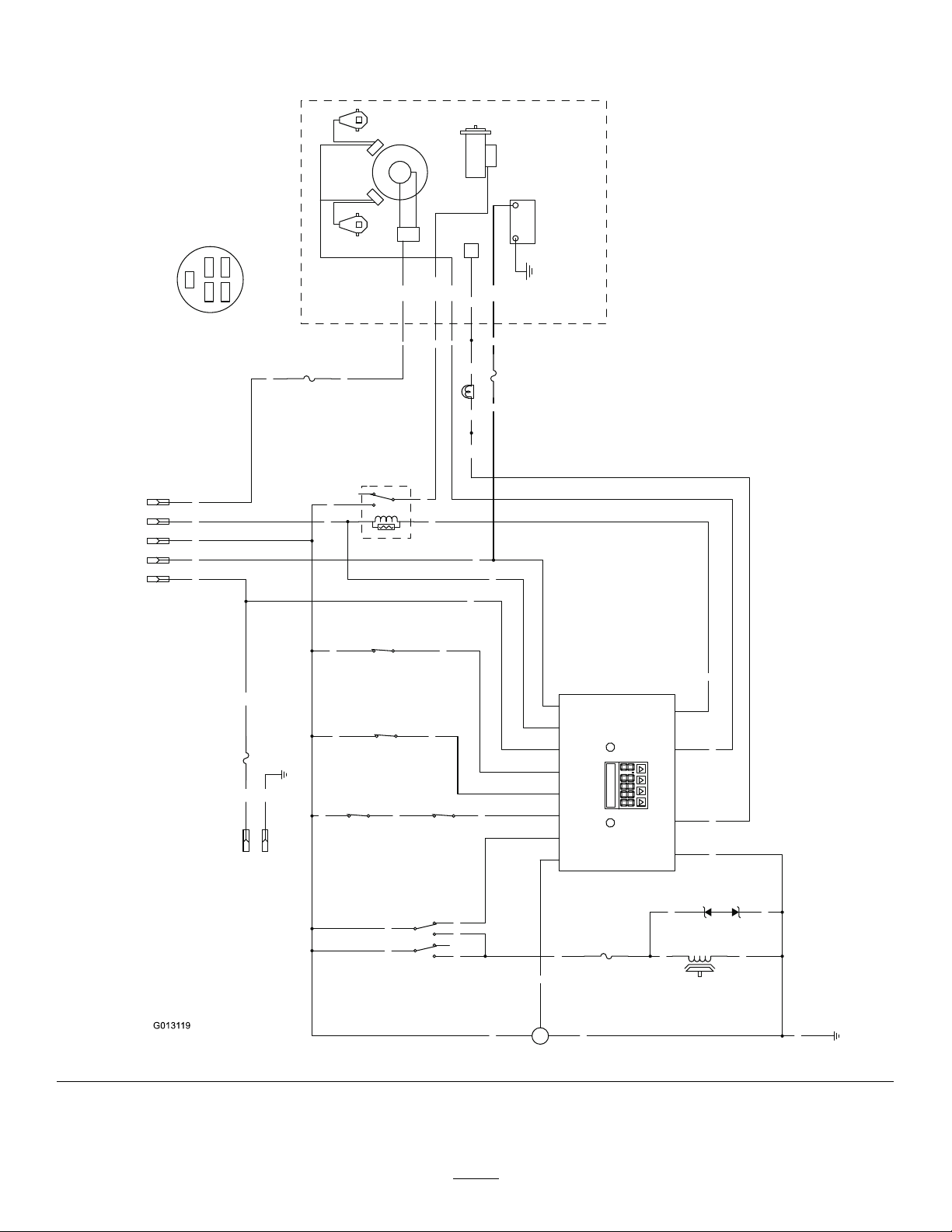
Schematics
G0131 19
BN
BN
BU
BK
Y
W
T
PK
BN
PK
OR
GN
S R
PK PK
PK
LTGR
GY
GY
PK
V
BN
V
OR
GN
OR
R
PK R BK
T
R
BK
GND
PK
BK
BN
BN
BK PK
BK
GND
15A
F4
GY
R
IBA
W
V
BU
V
V
BK
+
S
-
FUEL SENDER
10A
F3
(BRAKE)
SW6
PK
OR
R
F2
25A
PTO
CLUTCH
BU
1
2
5
4
7
8
(PTO SWITCH)
SW2
25A
LAMP
F1
(SEAT)
SW7
2
3
5
4
1
K2
(START RELAY)
TVS DIODE
U2
(NEUT_R)
SW5
B+
MAG
ECU
REG
START
AC
STARTER
+-
AC
IGNITION
MODULES
SPARK PLUGSPARK PLUG
KOHLER EFI
(NEUT_L)
SW4
12
B+
10
KEY_S
9
KEY_A
4
SEAT
11
BRAKE
2
NEUTRAL
3
PTO
5
FUEL
1
START_RELAY
7
MAGNETO
6
FUEL_SOLENOID
8
GROUND
HOUR METER
2
R A
I
A
4
7
1 3
6
5
A
3
SW1
1
B
B
C
B
8
2
4
5
(IGNITION)
6
5
1
KEY SW
OPTIONAL
ACCESSORIES
2
S
Ignition switch terminal locations
viewed from back
OFF = no connections
ON = BRIA
START = BRIS
BK = BLACK
BN = BROWN
BU = BLUE
GN = GREEN
GY = GREY
LT GR = LIGHT GREEN
OR = ORANGE
PK = PINK
R = RED
T = T
AN
V = VIOLET
W = WHITE
WireDiagram(Rev .A)
68
Page 69

Notes:
69
Page 70

Notes:
70
Page 71

Notes:
71
Page 72

TheToroTotalCoverageWarranty
ALimitedWarranty(seewarrantyperiodsbelow)Contractor
Landscape
Equipment
(LCE)
ConditionsandProductsCovered
TheToroCompanyanditsafliate,T oroWarrantyCompany,pursuanttoanagreement
betweenthem,jointlypromisetotheoriginalpurchasertorepairtheT oroProducts
listedbelowifdefectiveinmaterialsorworkmanship.
Thefollowingtimeperiodsapplyfromthedateofpurchasebytheoriginalowner:
ProductsWarrantyPeriod
21in.Mowers2yearsResidentialUse
1yearCommercialUse
4
•Engines
Honda–2years
Kawasaki–3years
30in.Mowers2yearsResidentialUse
1yearCommercialUse
4
•Engines
Mid-SizeWalk-BehindMowers
4
•Engines
GrandStand
4
•Engines
•Frame
®
ZMaster
•Engines
2000SeriesMowers
4
•Frame
®
ZMaster
•Engines
•Frame
ZMaster
•Engines
®
3000SeriesMowers
4
5000SeriesMowers
4
®
Mowers
Kawasaki–3years
2years
Kawasaki–3years
5yearsor1,200hours
3years
Lifetime(originalowneronly)
4yearsor500hours
3years
Lifetime(originalowneronly)
5yearsor1,200hours
3years
Lifetime(originalowneronly)
5yearsor1,200hours
KohlerCommand–2years
KohlerEFI–3years
•Frame
®
ZMaster
•Engines
6000SeriesMowers
4
•Frame
®
ZMaster
•Engines
7000SeriesMowers
4
•Frame
®
ZMaster
•Engines
8000SeriesMowers
4
•Frame
Lifetime(originalowneronly)
5yearsor1,200hours
Kawasaki–3years
Lifetime(originalowneronly)
5yearsor1,200hours
2years
Lifetime(originalowneronly)
2yearsor1,200hours
2years
Lifetime(originalowneronly)
AllMowers
•Battery90daysPartsandLabor
1yearPartsonly
•BeltsandTires90days
•Attachments1year
1
Residentialusemeansuseoftheproductonthesamelotasyourhome.Useatmorethanone
locationisconsideredcommercialuseandthecommercialwarrantywouldapply.
2
Whicheveroccursrst.
3
LifetimeFrameW arranty-Ifthemainframe,consistingofthepartsweldedtogethertoformthe
tractorstructurethatothercomponentssuchastheenginearesecuredto,cracksorbreaksin
normaluse,itwillberepairedorreplaced,atToro'soption,underwarrantyatnocostforpartsand
labor.Framefailureduetomisuseorabuseandfailureorrepairrequiredduetorustorcorrosion
arenotcovered.
4
SomeenginesusedonToroProductsarewarrantedbytheenginemanufacturer.
1
1
2
3
2
3
2
3
2
3
2
3
2
3
2
3
InstructionsforObtainingWarrantyService
IfyouthinkthatyourT oroProductcontainsadefectinmaterialsorworkmanship,
followthisprocedure:
1.ContactanyAuthorizedT oroServiceDealertoarrangeserviceattheir
dealership.T olocateadealerconvenienttoyou,refertotheYellowPagesof
yourtelephonedirectory(lookunder“LawnMowers”)oraccessourwebsite
atwww.Toro.com.Y oumayalsocallthenumberslistedinitem#3tousethe
24-hourT oroDealerlocatorsystem.
2.Bringtheproductandyourproofofpurchase(salesreceipt)totheService
Dealer.Thedealerwilldiagnosetheproblemanddetermineifitiscovered
underwarranty.
3.IfforanyreasonyouaredissatisedwiththeServiceDealer’sanalysisorwith
theassistanceprovided,contactusat:
RLCCustomerCareDepartment
ToroWarrantyCompany
811 1LyndaleAvenueSouth
Bloomington,MN55420-1 196
888-865-5676(U.S.Customers)
888-865-5691(Canadacustomers)
OwnerResponsibilities
YoumustmaintainyourT oroProductbyfollowingthemaintenanceprocedures
describedintheOperator'sManual.Suchroutinemaintenance,whetherperformedby
adealerorbyyou,isatyourexpense.
ItemsandConditionsNotCovered
Thereisnootherexpresswarrantyexceptforspecialemissionsystemcoverage
andenginewarrantycoverageonsomeproducts.Thisexpresswarrantydoesnot
coverthefollowing:
•Costofregularmaintenanceserviceorparts,suchaslters,fuel,lubricants,oil
changes,sparkplugs,airltersbladesharpeningorwornblades,cable/linkage
adjustments,orbrakeandclutchadjustments
•Componentsfailingduetonormalwear
•Anyproductorpartwhichhasbeenalteredormisusedorneglectedandrequires
replacementorrepairduetoaccidentsorlackofpropermaintenance
•Pickupanddeliverycharges
•RepairsorattemptedrepairsbyanyoneotherthananAuthorizedT oroService
Dealer
•Repairsnecessaryduetofailuretofollowrecommendedfuelprocedure(consult
Operator'sManualformoredetails)
–Removingcontaminantsfromthefuelsystemisnotcovered
–Useofoldfuel(morethanonemonthold)orfuelwhichcontainsmorethan
10%ethanolormorethat15%MTBE
–Failuretodrainthefuelsystempriortoanyperiodofnon-useoverone
month
GeneralConditions
AllrepairscoveredbythesewarrantiesmustbeperformedbyanAuthorizedT oro
ServiceDealerusingT oroapprovedreplacementparts.
NeitherTheToroCompanynorToroWarrantyCompanyisliableforindirect,
incidentalorconsequentialdamagesinconnectionwiththeuseoftheT oro
Productscoveredbythiswarranty ,includinganycostorexpenseofproviding
substituteequipmentorserviceduringreasonableperiodsofmalfunctionor
non-usependingcompletionofrepairsunderthiswarranty.
Allimpliedwarrantiesofmerchantability(thattheproductistforordinaryuse)
andtnessforuse(thattheproductistforaparticularpurpose)arelimitedto
thedurationoftheexpresswarranty.
Somestatesdonotallowexclusionsofincidentalorconsequentialdamages,
orlimitationsonhowlonganimpliedwarrantylasts,sotheaboveexclusions
andlimitationsmaynotapplytoyou.
Thiswarrantygivesyouspeciclegalrights,andyoumayalsohaveotherrights
whichvaryfromstatetostate.
CountriesOtherthantheUnitedStatesorCanada
CustomerswhohavepurchasedT oroproductsoutsidetheUnitedStatesorCanadashouldcontacttheirT oroDistributor(Dealer)toobtainguaranteepoliciesforyourcountry ,
province,orstate.IfforanyreasonyouaredissatisedwithyourDistributor'sserviceorhavedifcultyobtainingguaranteeinformation,contacttheToroimporter.Ifallother
remediesfail,youmaycontactusatT oroWarrantyCompany .
AustralianConsumerLaw:AustraliancustomerswillnddetailsrelatingtotheAustralianConsumerLaweitherinsidetheboxoratyourlocalT oroDealer.
374-0252RevG
 Loading...