

Page 1
FormNo.3394-296RevA
ZMaster
®
Professional5000and
6000SeriesRidingMower
with52in,60in,or72inTURBOFORCE
DischargeMower
ModelNo.74906—SerialNo.315000001andUp
ModelNo.74918—SerialNo.315000001andUp
ModelNo.74926—SerialNo.315000001andUp
ModelNo.74928—SerialNo.315000001andUp
ModelNo.74930—SerialNo.315000001andUp
ModelNo.78926—SerialNo.315000001andUp
ModelNo.78928—SerialNo.315000001andUp
®
Side
Registeratwww.T oro.com.
OriginalInstructions(EN)
*3394-296*A
Page 2
WARNING
CALIFORNIA
Proposition65Warning
Thisproductcontainsachemicalorchemicals
knowntotheStateofCaliforniatocausecancer,
birthdefects,orreproductiveharm.
Theengineexhaustfromthisproduct
containschemicalsknowntotheStateof
Californiatocausecancer,birthdefects,
orotherreproductiveharm.
ThissparkignitionsystemcomplieswithCanadianICES-002.
Becauseinsomeareastherearelocal,state,orfederal
regulationsrequiringthatasparkarresterbeusedonthe
engineofthismachine,asparkarresterisavailableas
anoption.Ifyourequireasparkarrester,contactyour
AuthorizedToroServiceDealer.
GenuineT orosparkarrestersareapprovedbytheUSDA
ForestryService.
Important:ItisaviolationofCaliforniaPublic
ResourceCodeSection4442touseoroperatetheengine
onanyforest-covered,brush-covered,orgrass-covered
landwithoutasparkarrestermufermaintainedin
workingorder,ortheengineconstricted,equipped,and
maintainedforthepreventionofre.Otherstatesor
federalareasmayhavesimilarlaws.
Theenclosed
informationregardingtheUSEnvironmentalProtection
Agency(EPA)andtheCaliforniaEmissionControl
Regulationofemissionsystems,maintenance,and
warranty.Replacementsmaybeorderedthroughthe
enginemanufacturer.
Engine Owner's Man ual
issuppliedfor
CustomerServiceandhavethemodelandserialnumbersof
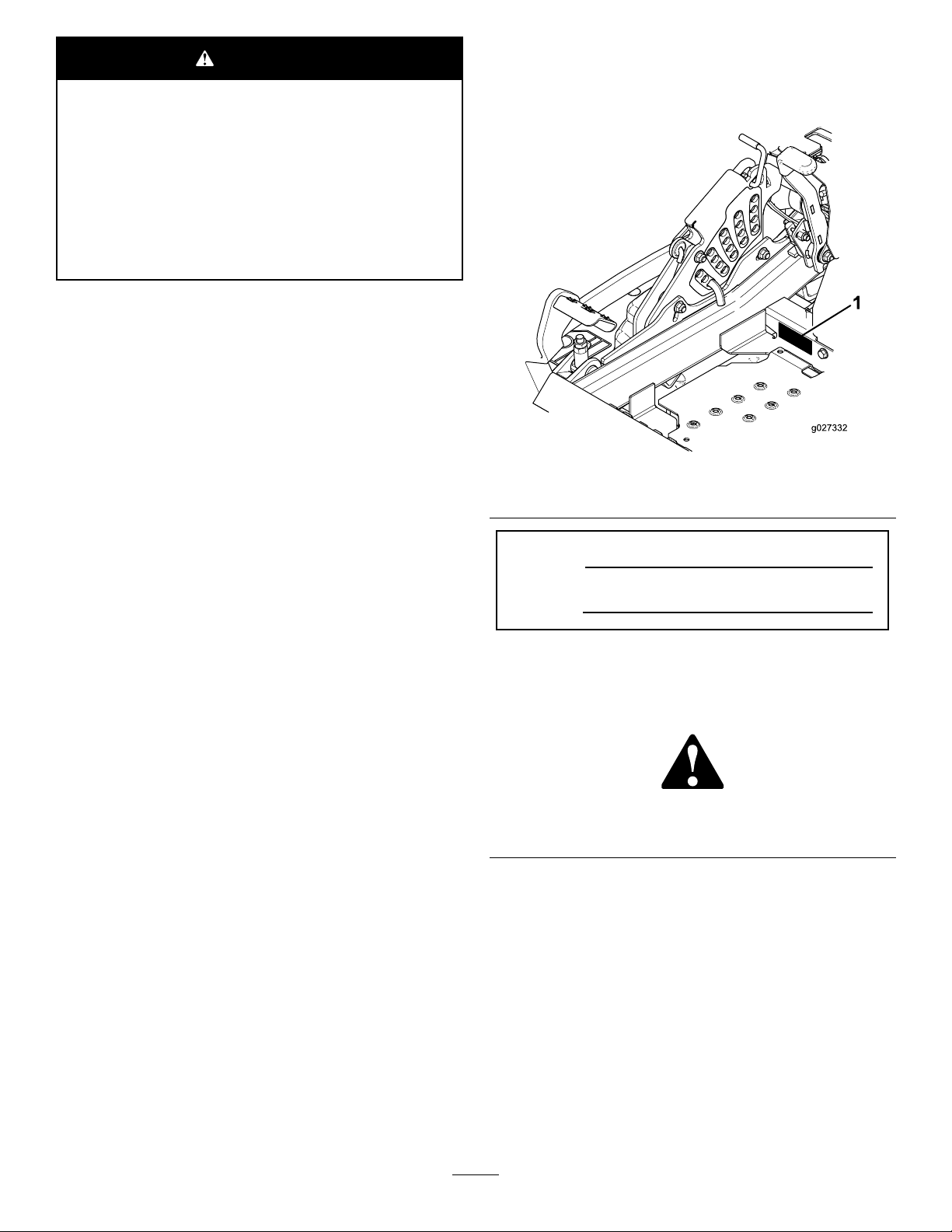
yourproductready.Figure1identiesthelocationofthe
modelandserialnumbersontheproduct.Writethenumbers
inthespaceprovided.
Figure1
1.Modelandserialnumberlocation
ModelNo.
SerialNo.
Thismanualidentiespotentialhazardsandhassafety
messagesidentiedbythesafetyalertsymbol(Figure2),
whichsignalsahazardthatmaycauseseriousinjuryordeath
ifyoudonotfollowtherecommendedprecautions.
Introduction
Thisrotary-blade,ridinglawnmowerisintendedtobeused
byresidentialhomeownersorprofessional,hiredoperators.
Itisdesignedprimarilyforcuttinggrassonwell-maintained
lawnsonresidentialorcommercialproperties.Itisnot
designedforcuttingbrushorforagriculturaluses.
Readthisinformationcarefullytolearnhowtooperateand
maintainyourproductproperlyandtoavoidinjuryand
productdamage.Youareresponsibleforoperatingthe
productproperlyandsafely.
YoumaycontactTorodirectlyatwww .Toro.comforproduct
safetyandoperationtrainingmaterials,accessoryinformation,
helpndingadealer,ortoregisteryourproduct.
Wheneveryouneedservice,genuineT oroparts,oradditional
information,contactanAuthorizedServiceDealerorToro
©2015—TheToro®Company
8111LyndaleAvenueSouth
Bloomington,MN55420
Figure2
1.Safetyalertsymbol
Thismanualuses2wordstohighlightinformation.
Importantcallsattentiontospecialmechanicalinformation
andNoteemphasizesgeneralinformationworthyofspecial
attention.
Contactusatwww.Toro.com.
2
PrintedintheUSA.
AllRightsReserved
Page 3

Contents
Safety...........................................................................4
SafeOperatingPractices...........................................4
SlopeIndicator.......................................................6
SafetyandInstructionalDecals.................................7
ProductOverview.........................................................13
Controls...............................................................13
Specications........................................................14
Operation....................................................................15
AddingFuel...........................................................15
CheckingtheEngine-OilLevel.................................16
BreakinginaNewMachine......................................16
UsingtheRolloverProtectionSystem(ROPS)............16
ThinkSafetyFirst...................................................17
OperatingtheParkingBrake....................................18
OperatingtheMowerBlade-ControlSwitch
(PTO)...............................................................18
OperatingtheThrottle............................................19
OperatingtheIgnitionSwitch..................................19
UsingtheFuel-ShutoffValve...................................19
StartingandStoppingtheEngine..............................19
TheSafety-InterlockSystem....................................20
DrivingForwardorBackward..................................21
StoppingtheMachine.............................................22
AdjustingtheHeightofCut.....................................22
AdjustingtheAnti-ScalpRollers...............................23
AdjustingtheFlowBafeCamLocks........................24
PositioningtheFlowBafe......................................24
PositioningtheSeat................................................25
UnlatchingtheSeat.................................................25
ChangingtheSeatSuspension..................................26
UsingtheDriveWheelReleaseValves.......................26
UsingtheSideDischarge.........................................26
TransportingtheMachine........................................27
LoadingtheMachine..............................................27
OperatingTips......................................................29
Maintenance.................................................................30
RecommendedMaintenanceSchedule(s)......................30
Lubrication...............................................................31
LubricatingtheMachine..........................................31
GreasingtheMower...............................................31
LubricatetheCasterWheelHubs..............................33
EngineMaintenance..................................................34
ServicingtheAirCleaner.........................................34
ServicingtheEngineOil..........................................35
ServicingtheSparkPlugs.........................................38
CheckSparkArrester(ifequipped)............................40
FuelSystemMaintenance...........................................40
ServicingtheElectronicFuelInjection
System..............................................................40
ReplacingtheLow-PressureFuelFilter......................40
ServicingtheHigh-PressureFuelFilter......................41
ServicingtheFuelTank...........................................41
ElectricalSystemMaintenance....................................41
ServicingtheBattery...............................................41
ServicingtheFuses.................................................43
Jump-StartingtheMachine......................................43
DriveSystemMaintenance.........................................44
CheckingtheSeatBelt.............................................44
CheckingtheKnobsontheRolloverProtection
System(ROPS)..................................................44
AdjustingtheTracking............................................45
CheckingtheTirePressure......................................45
CheckingtheWheelLugNuts..................................46
CheckingtheWheelHubSlottedNut........................46
AdjustingtheCasterPivotBearing............................46
UsingtheClutchShim............................................46
CoolingSystemMaintenance......................................48
CleaningtheEngineScreenandEngine-Oil
Cooler...............................................................48
CleaningtheEngineCoolingFinsand
Shrouds.............................................................48
CheckandCleantheHydraulic-UnitShrouds.............49
BrakeMaintenance....................................................50
AdjustingtheParkingBrake.....................................50
BeltMaintenance......................................................51
InspectingtheBelts................................................51
ReplacingtheMowerBelt........................................51
ReplacingtheHydraulicPumpDriveBelt...................52
ControlsSystemMaintenance.....................................53
AdjustingtheControlHandlePosition......................53
AdjustingtheMotion-ControlLinkage......................53
AdjustingtheMotion-ControlDamper.....................54
AdjustingtheMotion-ControlNeutralLock
Pivot.................................................................54
HydraulicSystemMaintenance....................................55
ServicingtheHydraulicSystem.................................55
MowerDeckMaintenance...........................................57
LevelingtheMowerDeck........................................57
ServicingtheCuttingBlades.....................................60
RemovingtheMowerDeck.....................................62
ReplacingtheGrassDeector..................................64
Cleaning...................................................................64
CleaningundertheMower.......................................64
DisposingofWaste.................................................64
Storage........................................................................65
CleaningandStorage..............................................65
Troubleshooting...........................................................66
Schematics...................................................................69
3
Page 4

Safety
Improperlyusingormaintainingthemachinecanresult
ininjury.Toreducethepotentialforinjury,complywith
thesesafetyinstructionsandalwayspayattentiontothe
safetyalertsymbol,whichmeans
Danger
withtheinstructionmayresultinpersonalinjuryor
death.
Thisproductiscapableofamputatinghandsandfeetand
throwingobjects.Alwaysfollowallsafetyinstructionsto
avoidseriousinjuryordeath.
Thisproductisdesignedforcuttingandrecyclinggrassor,
whenequippedwithagrassbagger,forcatchingcutgrass.
Anyuseforpurposesotherthanthesecouldprovedangerous
totheuserandbystanders.
—personalsafetyinstruction.Failuretocomply
SafeOperatingPractices
ThefollowinginstructionsareadaptedfromANSI
B71.4-2012.
Training
•ReadtheOperator'sManualandothertrainingmaterial.If
theoperator(s)ormechanic(s)cannotreadorunderstand
theinformationitistheowner'sresponsibilitytoexplain
thismaterialtothem.
•Becomefamiliarwiththesafeoperationoftheequipment,
operatorcontrols,andsafetysigns.
•Alloperatorsandmechanicsshouldbetrained.The
ownerisresponsiblefortrainingtheusers.
•Neverletchildrenoruntrainedpeopleoperateorservice
theequipment.Localregulationsmayrestricttheageof
theoperator.
•Theowner/usercanpreventandisresponsiblefor
accidentsorinjuriesoccurringtopeopleordamageto
property.
Preparation
•Evaluatetheterraintodeterminewhataccessoriesand
attachmentsareneededtoproperlyandsafelyperform
thejob.Onlyuseaccessoriesandattachmentsapproved
bythemanufacturer.
•Wearappropriateclothingincludinghardhat,safety
glasses,andhearingprotection.Longhair,looseclothing,
orjewelrymaygettangledinmovingparts.
•Inspecttheareawheretheequipmentistobeusedand
removeallobjectssuchasrocks,toys,andwirewhichcan
bethrownbythemachine.
•Checkthatoperator'spresencecontrols,safetyswitches,
andshieldsareattachedandfunctioningproperly.Donot
operateunlesstheyarefunctioningproperly.
Caution, W ar ning ,
Operation
•Lightningcancausesevereinjuryordeath.Iflightning
isseenorthunderisheardinthearea,donotoperate
themachine;seekshelter.
or
•Neverrunanengineinanenclosedarea.
•Onlyoperateingoodlight,keepingawayfromholesand
hiddenhazards.
•Besurealldrivesareinneutralandparkingbrakeis
engagedbeforestartingtheengine.Onlystarttheengine
fromtheoperator'sposition.
•Besureofyourfootingwhileusingthismachine,
especiallywhenbackingup.Walk;donotrun.Never
operateonwetgrass.Reducedfootingcouldcause
slipping.
•Slowdownanduseextracareonhillsides.Besureto
travelsidetosideonhillsides.Turfconditionscanaffect
thestabilityofthemachine.Usecautionwhileoperating
neardrop-offs.
•Slowdownandusecautionwhenmakingturnsandwhen
changingdirectionsonslopes.
•Neverraisedeckwiththebladesrunning.
•NeveroperatewiththePTOshieldorotherguardsnot
securelyinplace.Besureallinterlocksareattached,
adjustedproperly ,andfunctioningproperly.
•Neveroperatewiththedischargedeectorraised,
removedoraltered,unlessusingagrasscatcher.
•Donotchangetheenginegovernorsettingoroverspeed
theengine.
•Stoponlevelground,disengagedrives,engagethe
parkingbrake(ifprovided),andshutofftheenginebefore
leavingtheoperator'spositionforanyreason,including
emptyingthecatchersoruncloggingthechute.
•Stopequipmentandinspectbladesafterstrikingobjects
orifanabnormalvibrationoccurs.Makenecessary
repairsbeforeresumingoperations.
•Keephandsandfeetawayfromthecuttingunit.
•Lookbehindanddownbeforebackinguptobesureof
aclearpath.
•Nevercarrypassengersonthemachine.
•Keeppetsandbystandersaway .
•Slowdownandusecautionwhenmakingturnsand
crossingroadsandsidewalks.Stopbladesifnotmowing.
•Beawareofthemowerdischargedirectionanddonot
pointitatanyone.
•Donotoperatethemowerundertheinuenceofalcohol
ordrugs.
•Usecarewhenloadingorunloadingthemachineinto
orfromatrailerortruck.
•Usecarewhenapproachingblindcorners,shrubs,trees,
orotherobjectsthatmayobscurevision.
4
Page 5

RolloverProtectionSystem
(ROPS)—UseandMaintenance
•TheROPSisanintegralandeffectivesafetydevice.Keep
afoldingROPSintheraisedandlockedpositionanduse
theseatbeltwhenoperatingthemachine.
•LowerafoldingROPStemporarilyonlywhenabsolutely
necessary.Donotweartheseatbeltwhenfoldeddown.
•Beawarethereisnorolloverprotectionwhenafolded
ROPSisinthedownposition.
•Iffuelisspilledonclothing,changeclothingimmediately.
•Neveroverllfueltank.Replacefuelcapandtighten
securely.
MaintenanceandStorage
•Disengagedrives,settheparkingbrake,stoptheengine
andremovethekeyordisconnectthespark-plugwire.
Waitforallmovementtostopbeforeadjusting,cleaning
orrepairingthemachine.
•Becertainthattheseatbeltcanbereleasedquicklyin
theeventofanemergency.
•Checktheareatobemowedandneverfolddowna
foldingROPSinareaswherethereareslopes,dropoffs
orwater.
•Checkcarefullyforoverheadclearances(i.e.branches,
doorways,electricalwires)beforedrivingunderany
objectsanddonotcontactthem.
•KeeptheROPSinsafeoperatingconditionby
periodicallythoroughlyinspectingfordamageand
keepingallmountingfastenerstight.
•ReplaceadamagedROPS.Donotrepairorrevise.
•DonotremovetheROPS.
•AnyalterationstoaROPSmustbeapprovedbythe
manufacturer.
SafeHandlingofFuels
•Toavoidpersonalinjuryorpropertydamage,use
extremecareinhandlinggasoline.Gasolineisextremely
ammableandthevaporsareexplosive.
•Extinguishallcigarettes,cigars,pipes,andothersources
ofignition.
•Useonlyanapprovedfuelcontainer.
•Neverremovefuelcaporaddfuelwiththeengine
running.
•Allowenginetocoolbeforerefueling.
•Neverrefuelthemachineindoors.
•Neverstorethemachineorfuelcontainerwherethereis
anopename,spark,orpilotlightsuchasonawater
heateroronotherappliances.
•Cleangrassanddebrisfromthecuttingunit,thedrives,
themufers,andtheenginetohelppreventres.Clean
upoilorfuelspillage.
•Lettheenginecoolbeforestoringanddonotstorenear
ame.
•Shutoffthefuelwhilestoringortransporting.Donot
storefuelnearamesordrainindoors.
•Parkthemachineonlevelground.Settheparkingbrake.
Neverallowuntrainedpersonneltoservicethemachine.
•Usejackstandstosupportcomponentswhenrequired.
•Carefullyreleasepressurefromcomponentswithstored
energy.
•Disconnectthebatteryorthespark-plugwirebefore
makinganyrepairs.Disconnectthenegativeterminal
rstandthepositivelast.Connectthepositiverstand
negativelast.
•Usecarewhencheckingtheblades.Wraptheblade(s)
orwearthickly-paddedgloves,andusecautionwhen
servicingthem.Onlyreplaceblades.Neverstraighten
orweldthem.
•Keephandsandfeetawayfrommovingparts.Ifpossible,
donotmakeadjustmentswiththeenginerunning.
•Keepallpartsingoodworkingconditionandallhardware
tightened.Replaceallwornordamageddecals.
•Tobestprotectyourinvestmentandmaintainoptimal
performanceofyourToroequipment,countonToro
genuineparts.Whenitcomestoreliability,Torodelivers
replacementpartsdesignedtotheexactengineering
specicationsofourequipment.Forpeaceofmind,insist
onTorogenuineparts.
•Neverllcontainersinsideavehicleoronatruckor
trailerbedwithaplasticliner.Alwaysplacecontainerson
thegroundawayfromyourvehiclebeforelling.
•Removeequipmentfromthetruckortrailerandrefuelit
ontheground.Ifthisisnotpossible,thenrefuelsuch
equipmentwithaportablecontainer,ratherthanfroma
fueldispensernozzle.
•Keepthenozzleincontactwiththerimofthefueltank
orcontaineropeningatalltimesuntilfuelingiscomplete.
•Donotuseanozzlelockopendevice.
Hauling
•Usecarewhenloadingorunloadingthemachineintoa
trailerortruck.
•Usefullwidthrampsforloadingthemachineintoatrailer
ortruck.
•Tiethemachinedownsecurelyusingstraps,chains,cable,
orropes.Bothfrontandrearstrapsshouldbedirected
downandoutwardfromthemachine.
5
Page 6

SlopeIndicator
G011841
Figure3
Thispagemaybecopiedforpersonaluse.
1.Themaximumslopeyoucansafelyoperatethemachineonis15degrees.Usetheslopecharttodeterminethedegreeofslope
ofhillsbeforeoperating.Donotoperatethismachineonaslopegreaterthan15degrees.Foldalongtheappropriateline
tomatchtherecommendedslope.
2.Alignthisedgewithaverticalsurface,atree,building,fencepole,etc.
3.Exampleofhowtocompareslopewithfoldededge.
6
Page 7
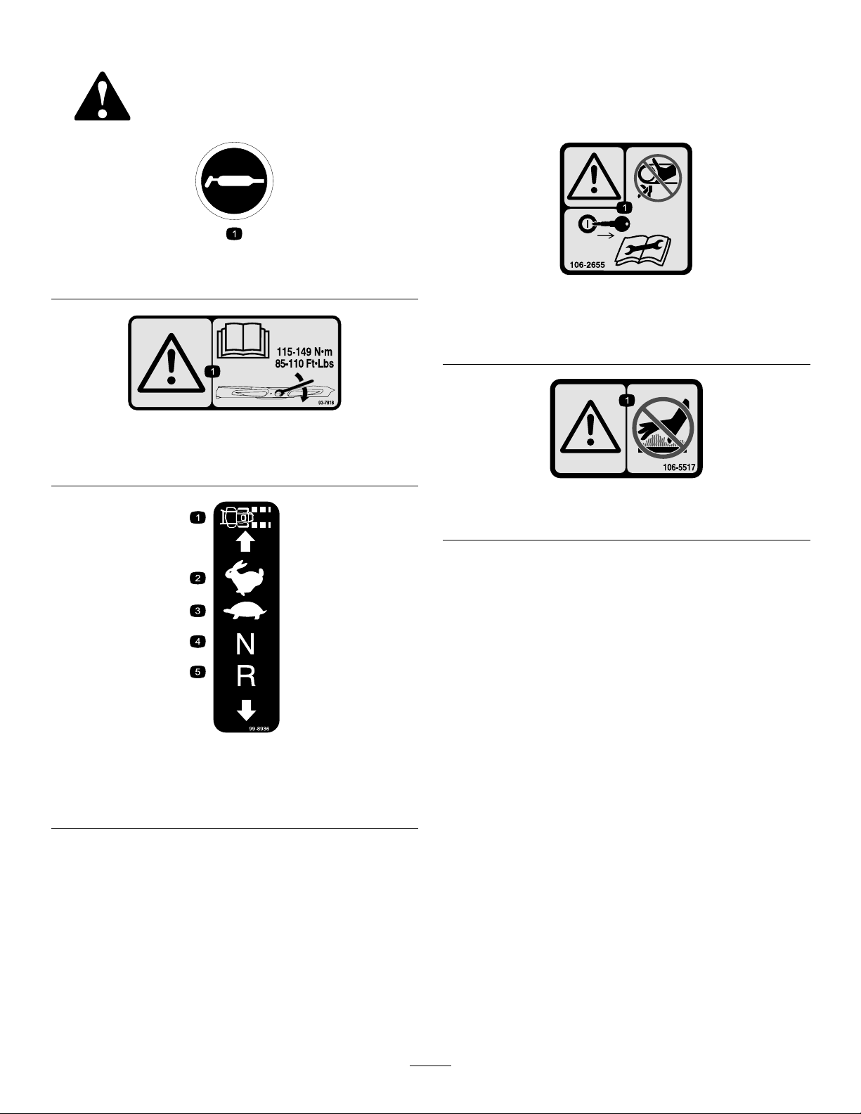
SafetyandInstructionalDecals
Safetydecalsandinstructionsareeasilyvisibletotheoperatorandarelocatednearanyareaofpotential
danger.Replaceanydecalthatisdamagedorlost.
58-6520
1.Grease
93-7818
1.Warning—readtheOperator'sManualforinstructionson
torquingthebladebolt/nutto115-149N-m(85-110ft-lb).
106-2655
1.Warning-donottouchorapproachmovingbelts;remove
theignitionkeyandreadtheinstructionsbeforeservicing
orperformingmaintenance.
106-5517
1.Warning—donottouchthehotsurface.
99-8936
1.Machinespeed4.Neutral
2.Fast5.Reverse
3.Slow
7
Page 8
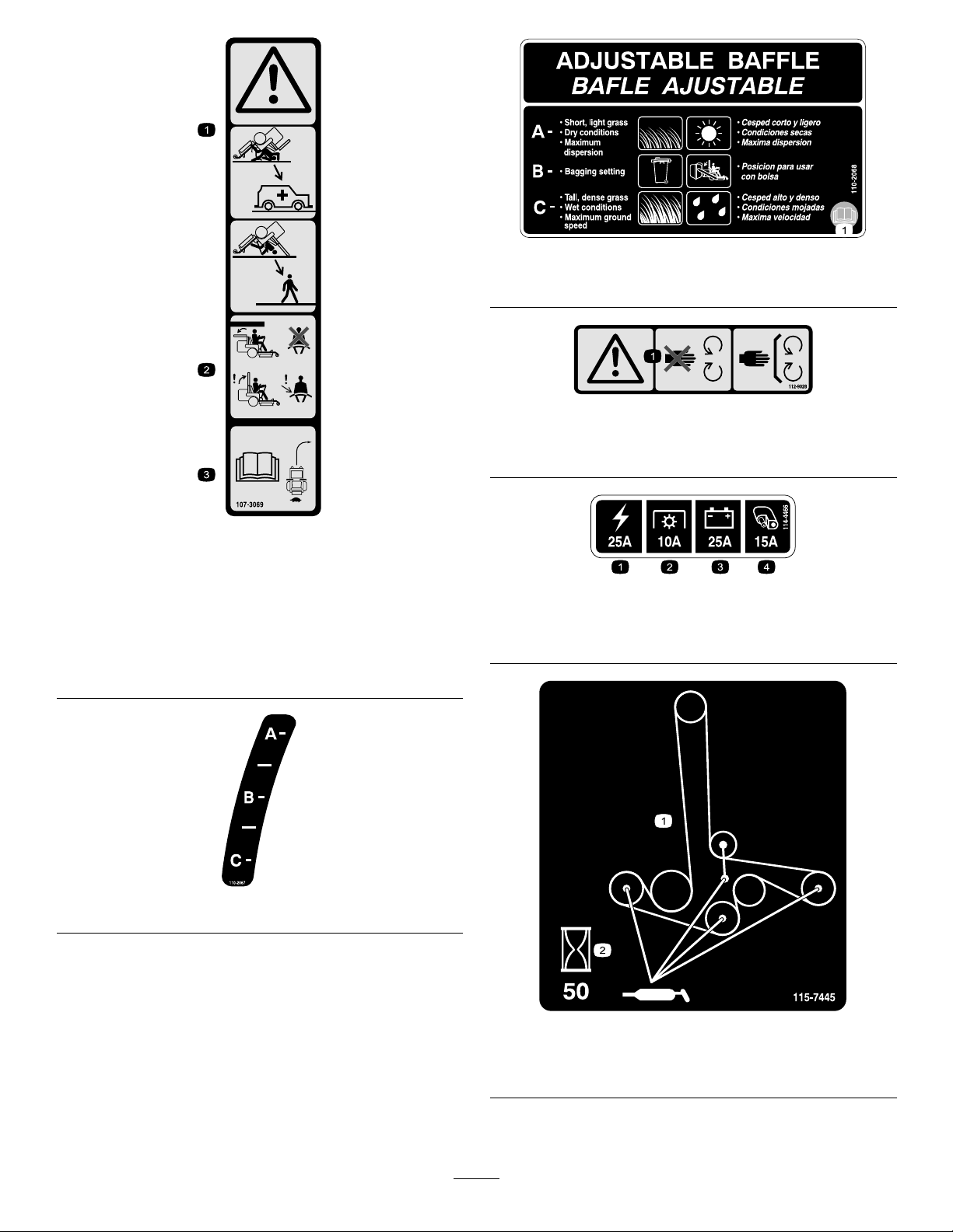
107-3069
1.Warning-thereisnorolloverprotectionwhentherollbaris
down.
2.Toavoidinjuryordeathfromarolloveraccident,keepthe
rollbarinthefullyraisedandlockedpositionandwear
theseatbelt.Lowertherollbaronlywhenabsolutely
necessary;donotweartheseatbeltwhentherollbaris
down.
3.ReadtheOperator’smanual;driveslowlyandcarefully.
110-2068
1.ReadtheOperator'sManual.
112-9028
1.Warning—stayawayfrommovingparts;keepallguardsin
place.
114-4466
1.Main,25A
2.PTO,10A
3.Charge,25A
4.Auxiliary,15A
110-2067
115-7445
1.Greasepulleysandspindles
2.Maintenanceinterval—50hours
8
Page 9
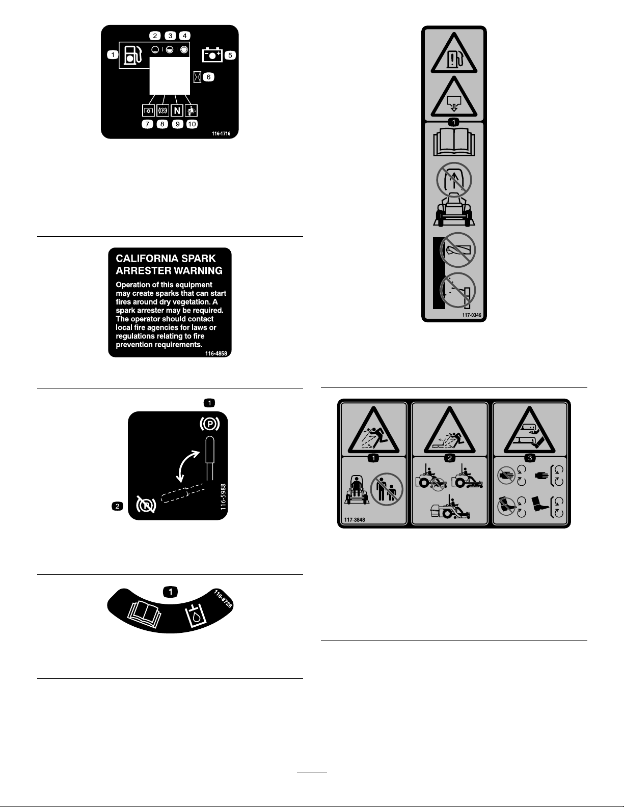
116-1716
1.Fuel6.Hourmeter
2.Empty
3.Half
4.Full9.Neutral
5.Battery
7.PTO
8.Parkingbrake
10.Operatorpresenceswitch
116-4858
117-0346
1.Fuelleakhazard—readtheOperator'sManual;donot
attempttoremovetherollbar;donotweld,drillormodify
therollbarinanyway.
116-5988
1.Parkingbrake—engaged2.Parking
brake—disengaged
116-8726
1.ReadtheOperator’sManualforrecommendedhydrooil.
117-3848
1.Thrownobjecthazard—keepbystandersasafedistance
fromthemachine
2.Thrownobjecthazard,mower-donotoperatewithoutthe
deector,dischargecoverorgrasscollectionsystemin
place.
3.Cutting/dismembermentofhandorfoot—stayawayfrom
movingparts;keepallguardsandshieldsinplace.
9
Page 10

117-3864
1.ReadtheOperator’s
Manual.
1.Fast
2.Variablespeedcontrol
2.Filltobottomofllerneck;
warning—donotoverll
thetank.
121–7586
3.Slow
4.Powertake-off(PTO)
126-2055
1.ReadtheOperator’s
manual
2.Lock
126-4398
3.Unlock
1.Wheellugnuttorque95ft-lb(129N-m)(4x)
2.Wheelhubnuttorque235ft-lb(319N-m)
3.ReadandunderstandtheOperator’smanualbefore
performinganymaintenance,checktorqueafterrst100
hoursthenevery500hoursthereafter.
1.ReadtheOperator's
Manual.
2.Height-of-cut
1.Maximumdrawbarpull36
kg(80lb)
127-0326
3.Removethekeyfrom
theignitionandreadthe
Operator'sManualbefore
performingmaintenance
orservicingthemachine.
131-4036
2.ReadtheOperator's
Manual.
10
Page 11
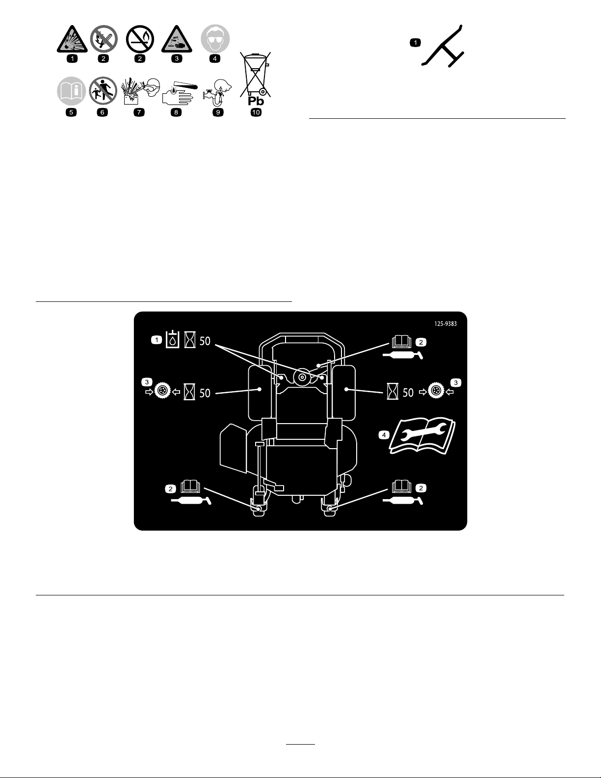
BatterySymbols
Someorallofthesesymbolsareonyourbattery
Manufacturer'sMark
1.Indicatesthebladeisidentiedasapartfromtheoriginal
machinemanufacturer.
1.Explosionhazard
2.Nore,opename,or
smoking.
3.Causticliquid/chemical
burnhazard
4.Weareyeprotection9.Flusheyesimmediately
5.ReadtheOperator's
Manual.
6.Keepbystandersasafe
7.Weareyeprotection;
8.Batteryacidcancause
10.Containslead;donot
distancefromthebattery.
explosivegasescan
causeblindnessandother
injuries
blindnessorsevereburns.
withwaterandgetmedical
helpfast.
discard.
125–9383
1.Checkhydraulicoilevery50operatinghours.3.Checkthetirepressureevery50operatinghours.
2.ReadtheOperator’sManualforinformationonlubricating
themachine.
4.ReadtheOperator’sManualbeforeservicingorperforming
maintenance.
11
Page 12
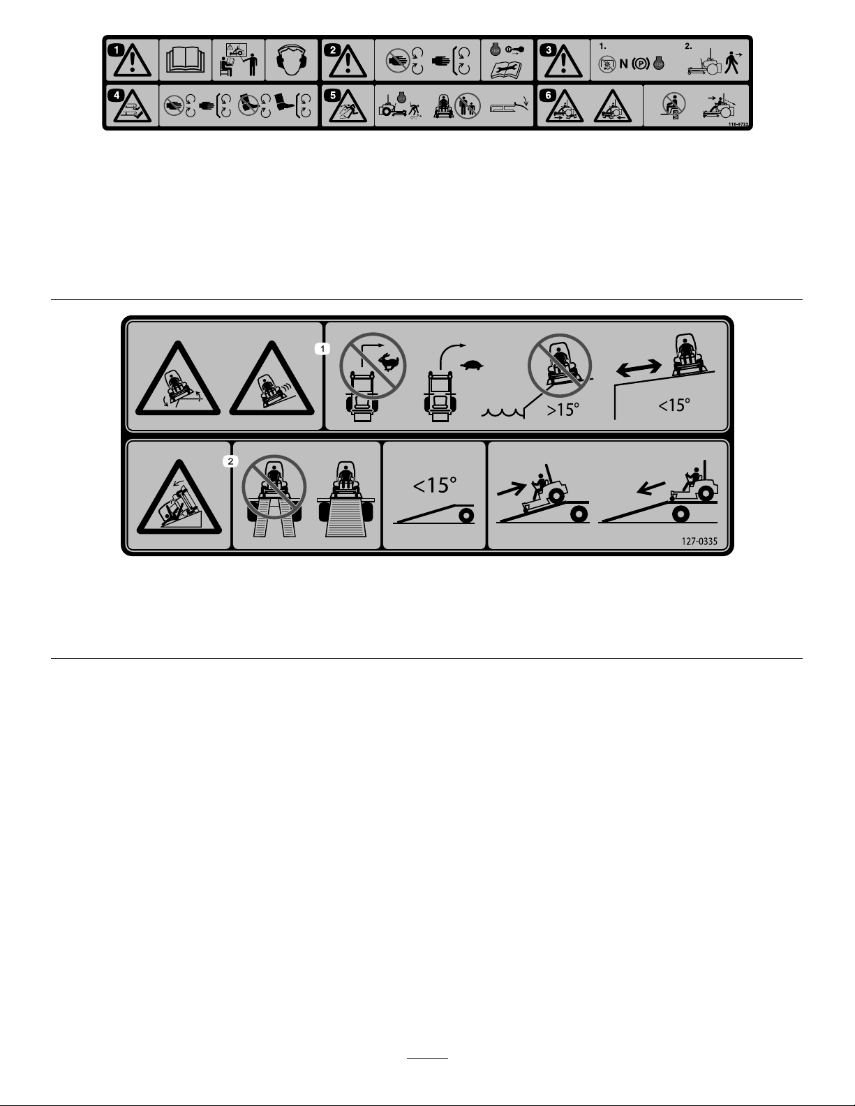
116-8722
1.Warning-ReadtheOperator’sManual.DoNotoperatethis
machineunlessyouaretrained.Wearhearingprotection.
2.Warning-Stayawayfrommovingparts;keepallguards
inplace.Stopengineandremovekeybeforeadjusting,
servicing,orcleaning.
3.Warning-DisengagePTO,movedriveleversouttoneutral
lockposition,engageparkingbrake,andstopenginebefore
leavingtheoperator’sposition.
4.Cutting/dismembermentofhandorfoot-stayawayfrom
movingparts;keepallguardsandshieldsinplace.
5.Thrownobjecthazard-Pickupobjectsthatcouldbethrown
bymower.Donotoperatewhenpeopleandpetsareinthe
area.Keepdeectorinplace.
6.Crushing/dismembermenthazardofbystanders-donotcarry
passengers,lookforwardanddownwhenoperatingthe
machine,lookbehindanddownwhenreversing.
127–0335
1.Tippinghazardonslopes—donotmakesudden,tightturns;
makeslow,wideturns;donotuseonslopesnearopenwater;
donotusethismachineonslopesgreaterthan15degrees.
2.Ramphazard—whenloadingontoatrailer,donotusedual
ramps;onlyuseasingularrampwideenoughforthemachine
andthathasaninclinelessthan15degrees;backupthe
ramp(inreverse)anddriveforwardofftheramp.
12
Page 13
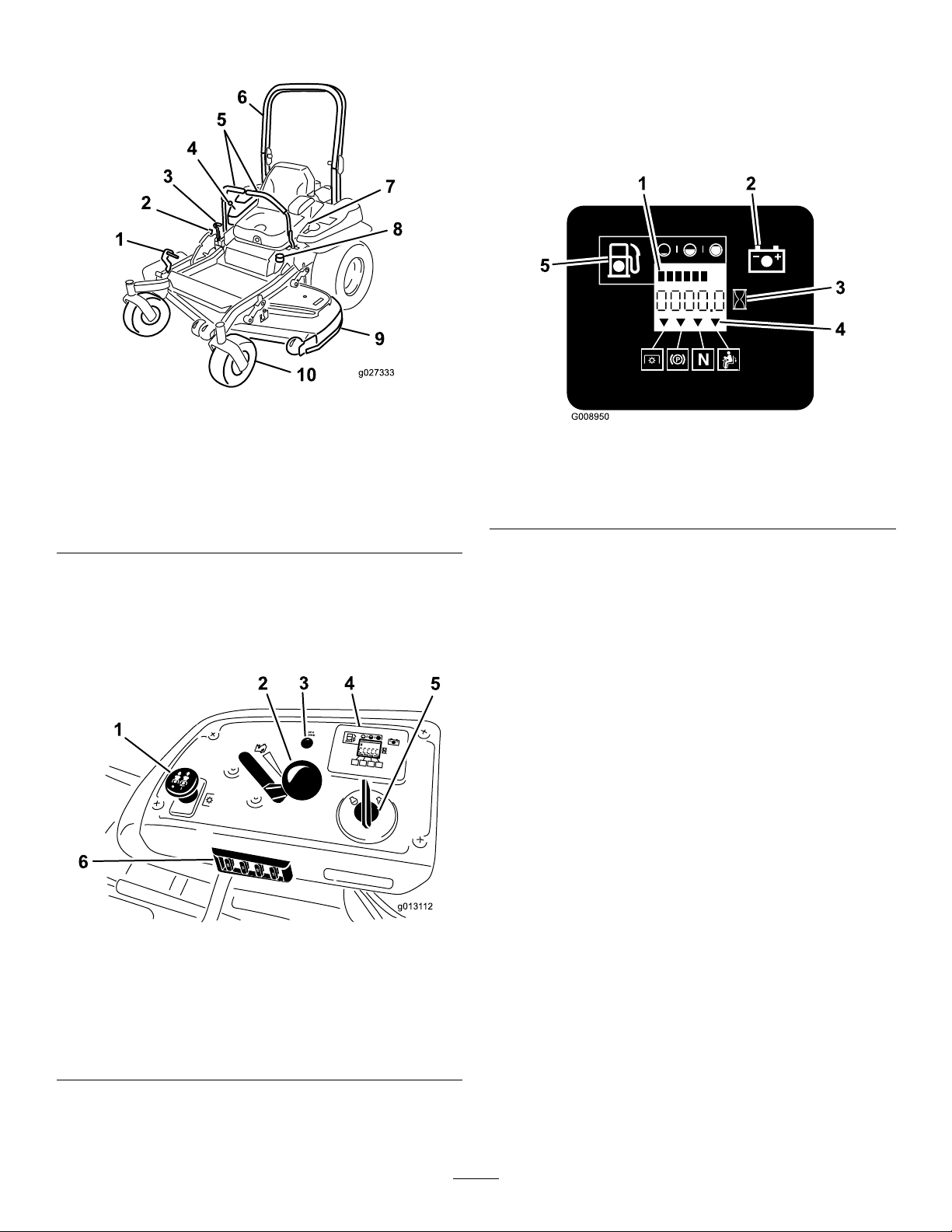
ProductOverview
g027333
g0131 12
1
2
3
4
5
6
25
25
10
15
C
H
ECK
ENG
IN
E
FuelGauge
Thefuelgaugeislocatedwiththehourmeter,andthebars
lightupwhentheignitionswitchison(Figure6).
Theindicatorlightappearswhenthefuellevelis
low—approximately3.8L(1USgallon)remaininginthe
fueltank.
Figure4
1.Height-of-cutdecklift
pedal
2.Transportlock
3.Parkingbrakelever8.Fuelcap
4.Controls
5.Motion-controllevers
6.Rollbar
7.Seatbelt
9.Mowerdeck
10.Casterwheel
Controls
Becomefamiliarwithallthecontrolsbeforeyoustartthe
engineandoperatethemachine(Figure4andFigure5).
Figure5
1.PTOSwitch
2.Throttlecontrol5.Ignitionswitch
3.Malfunctionindicatorlight
(MIL)
4.Hour
meter/Safety-interlock
display/Fuelgauge
6.Fuses
Figure6
1.Fuelgauge(bars)4.Safety-interlocksymbols
2.Batterylight
3.Hourmeter
5.Low-fuelindicatorlight
HourMeter
Thehourmeterrecordsthenumberofhourstheenginehas
operated.Itoperateswhentheengineisrunning.Usethese
timesforschedulingregularmaintenance(Figure6).
Safety-InterlockIndicators
Therearesymbolsonthehourmeterandtheindicatewitha
blacktrianglethattheinterlockcomponentisinthecorrect
position(Figure6).
BatteryIndicatorLight
WhentheignitionkeyisinitiallyturnedtotheRunposition
forafewseconds,thebatteryvoltagewillbedisplayedinthe
areawherethehoursarenormallydisplayed.
Thebatterylightturnsonwhentheignitionisturnedonand
whenthechargeisbelowthecorrectoperatinglevel(Figure
6).
ThrottleControl
ThethrottlecontrolisvariablebetweenFastandSlow.
Blade-ControlSwitch(PTO)
Theblade-controlswitch(PTO)isusedtoengagetheelectric
clutchanddrivethemowerblades.Pulltheswitchupto
engagethebladesandrelease.Todisengagetheblades,
pushtheblade-controlswitch(PTO)downormovea
motion-controlleverintotheneutrallockposition.
13
Page 14
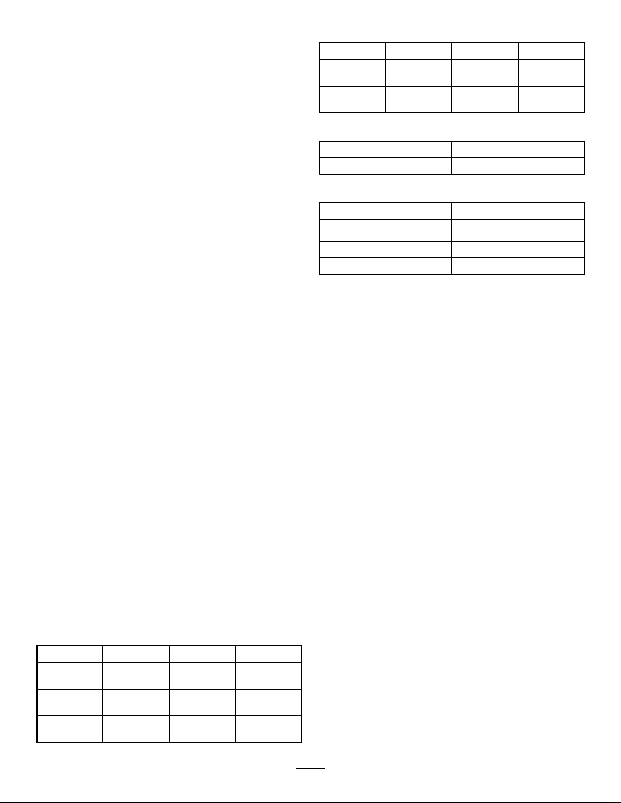
IgnitionSwitch
Length:
Thisswitchisusedtostartthemowerengineandhasthree
positions:Start,RunandOff.
Motion-ControlLevers
Themotion-controlleversareusedtodrivethemachine
forward,reverse,andturneitherdirection.
Neutral-LockPosition
Theneutral-lockpositionisusedwiththesafety-interlock
systemtoengageandtodetermineneutralposition.
Fuel-ShutoffValve
Closethefuel-shutoffvalve(undertheseat)when
transportingorstoringthemower.
ElectronicControlUnitMalfunction
IndicatorLight
Theelectroniccontrolunit(ECU)continuouslymonitorsthe
operationoftheEFIsystem.
52-inchDeck60-inchDeck72-inchDeck
RollBar—Up
Roll
Bar—Down
201cm(79
inches)
206cm(81
inches)
211.1cm
(83.1inches)
215.4cm
(84.8inches)
Height:
RollBar—UpRollBar—Down
179.1cm(70.5inches)118.9cm(46.8inches)
Weight:
ModelWeight
74906
74926,78926,and74930
74918,74928,and78928
533kg(1 174lbs)
569kg(1255lb)
612kg(1350lb)
218.7cm
(86.1inches)
223.0cm
(87.8inches)
Ifthesystemdetectsaproblemorfault,themalfunction
indicatorlight(MIL)illuminates.
TheMIListheredlightlocatedintherightconsolepanel.
IftheMILilluminates,performtheinitialtroubleshooting
checks;refertotheMILsectioninTroubleshooting(page66).
Ifthesechecksdonotcorrecttheproblem,furtherdiagnosis
andservicingbyanAuthorizedServiceDealerisnecessary.
Attachments/Accessories
AselectionofToroapprovedattachmentsandaccessoriesis
availableforusewiththemachinetoenhanceandexpand
itscapabilities.ContactyourAuthorizedServiceDealeror
Distributororgotowww .Toro.comforalistofallapproved
attachmentsandaccessories.
Specications
Note:Specicationsanddesignaresubjecttochange
withoutnotice.
Width:
52-inchDeck60-inchDeck72-inchDeck
WithoutDeck
DeectorUp146cm(58
Deector
Down
116cm(46
inches)
inches)
172cm(68
inches)
134.6cm
(53.0inches)
156.8cm
(61.7inches)
192.2cm
(75.7inches)
150.1cm
(59.1inches)
187cm(73.6
inches)
222.4cm
(87.6inches)
14
Page 15

Operation
Note:Determinetheleftandrightsidesofthemachine
fromthenormaloperatingposition.
DANGER
Incertainconditionsduringfueling,static
electricitycancauseasparkwhichcanignitethe
gasolinevapors.Areorexplosionfromgasoline
canburnyouandothersandcandamageproperty.
AddingFuel
•Forbestresults,useonlyclean,fresh(lessthan30days
old),unleadedgasolinewithanoctaneratingof87or
higher((R+M)/2ratingmethod).
•Ethanol:Gasolinewithupto10%ethanol(gasohol)
or15%MTBE(methyltertiarybutylether)byvolume
isacceptable.EthanolandMTBEarenotthesame.
Gasolinewith15%ethanol(E15)byvolumeisnot
approvedforuse.Neverusegasolinethatcontainsmore
than10%ethanolbyvolume,suchasE15(contains15%
ethanol),E20(contains20%ethanol),orE85(contains
upto85%ethanol).Usingunapprovedgasolinemay
causeperformanceproblemsand/orenginedamage
whichmaynotbecoveredunderwarranty.
•Donotusegasolinecontainingmethanol.
•Donotstorefueleitherinthefueltankorfuelcontainers
overthewinterunlessafuelstabilizerisused.
•Donotaddoiltogasoline.
DANGER
Incertainconditions,gasolineisextremely
ammableandhighlyexplosive.Areorexplosion
fromgasolinecanburnyouandothersandcan
damageproperty.
•Fillthefueltankoutdoors,inanopenarea,
whentheengineiscold.Wipeupanygasoline
thatspills.
•Neverllthefueltankinsideanenclosedtrailer.
•Donotllthefueltankcompletelyfull.Add
gasolinetothefueltankuntilthelevelis6to13
mm(1/4to1/2inch)belowthebottomofthe
llerneck.Thisemptyspaceinthetankallows
gasolinetoexpand.
•Neversmokewhenhandlinggasoline,andstay
awayfromanopenameorwheregasoline
fumesmaybeignitedbyaspark.
•Storegasolineinanapprovedcontainerand
keepitoutofthereachofchildren.Neverbuy
morethana30-daysupplyofgasoline.
•Donotoperatewithouttheentireexhaust
systeminplaceandinproperworkingcondition.
•Alwaysplacegasolinecontainersontheground
awayfromyourvehiclebeforelling.
•Donotllgasolinecontainersinsideavehicleor
onatruckortrailerbed,becauseinteriorcarpets
orplastictruck-bedlinersmayinsulatethe
containerandslowthelossofanystaticcharge.
•Whenpractical,removegas-poweredequipment
fromthetruckortrailerandfueltheequipment
withthewheelsontheground.
Ifthisisnotpossible,thenfuelsuchequipment
onatruckortrailerfromaportablecontainer,
ratherthanfromagasoline-dispensernozzle.
•Ifagasolinedispensermustbeused,keepthe
nozzleincontactwiththerimofthefueltank
orcontaineropeningatalltimesuntilfuelingis
complete.
WARNING
Gasolineisharmfulorfatalifswallowed.Long-term
exposuretovaporscancauseseriousinjuryand
illness.
•Avoidprolongedbreathingofvapors.
•Keepfaceawayfromnozzleandgastankor
conditionerbottleopening.
•Avoidcontactwithskin;washoffspillagewith
soapandwater.
UsingFuelStabilizer/Conditioner
Useafuelstabilizer/conditionerinthemachinetokeepthe
fuelfreshduringstorageof90daysorless.Ifyouarestoring
themachineforlonger,drainthefueltank;refertoStorage
(page65).
Important:Donotusefueladditivescontaining
methanolorethanol.
Addthecorrectamountoffuelstabilizer/conditionertothe
fuel,andfollowthedirectionsofthemanufacturer.
Note:Fuelstabilizer/conditionerismosteffectivewhen
mixedwithfreshgasoline.Tominimizethechanceofvarnish
depositsinthefuelsystem,usefuelstabilizeratalltimes.
15
Page 16
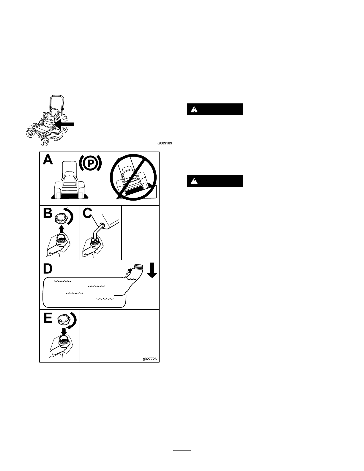
FillingtheFuelTank
G009189
1.Parkthemachineonlevelground.
2.Shuttheengineoffandsettheparkingbrake.
3.Cleanaroundthefuel-tankcapandremoveit.Add
regularunleadedgasolinetothefueltankuntilthelevel
is6to13mm(1/4to1/2inch)belowthebottom
ofthellerneck.Thisspaceinthetankallowsthe
gasolinetoexpand.Donotllthefueltankcompletely
full;referto(Figure7).
BreakinginaNewMachine
Newenginestaketimetodevelopfullpower.Mowerdecks
anddrivesystemshavehigherfrictionwhennew,placing
additionalloadontheengine.Allow40to50hoursof
break-intimefornewmachinestodevelopfullpowerand
bestperformance.
UsingtheRolloverProtection System(ROPS)
WARNING
Toavoidinjuryordeathfromrollover:keeptheroll
barinthefullyraisedlockedpositionandusethe
seatbelt.
Ensurethattherearpartoftheseatissecuredwith
theseatlatch.
WARNING
Thereisnorolloverprotectionwhentherollbaris
inthedownposition.
•Lowertherollbaronlywhenabsolutely
necessary.
•Donotweartheseatbeltwhentherollbaris
inthedownposition.
•Driveslowlyandcarefully.
•Raisetherollbarassoonasclearancepermits.
•Checkcarefullyforoverheadclearances(i.e.
branches,doorways,electricalwires)before
drivingunderanyobjectsanddonotcontact
them.
Important:Lowertherollbaronlywhenabsolutely
necessary.
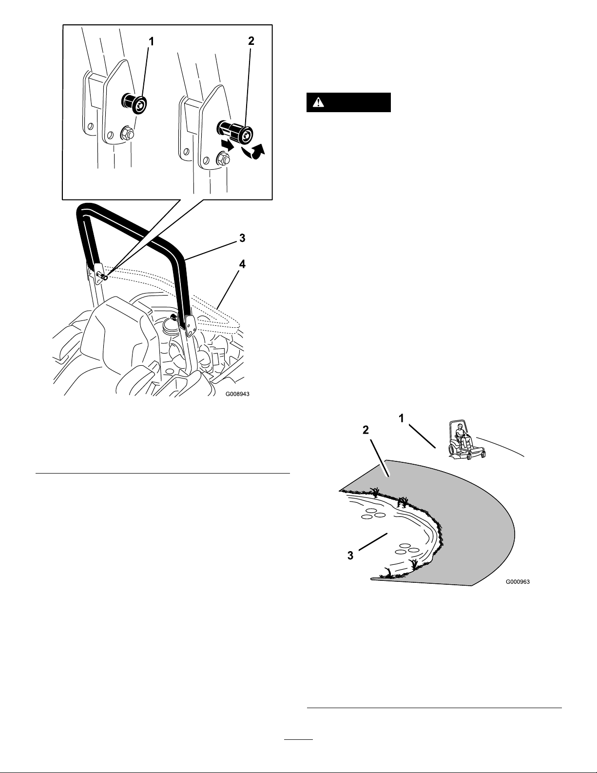
1.Tolowertherollbar,applyforwardpressuretothe
upperpartoftherollbar.
2.Pullbothknobsoutandrotatethem90°sothatthey
arenotengaged(Figure8).
Figure7
CheckingtheEngine-OilLevel
Beforeyoustarttheengineandusethemachine,check
theoillevelintheenginecrankcase;refertoCheckingthe
Engine-OilLevel(page35).
3.Lowertherollbartothedownposition(Figure8).
16
Page 17
ThinkSafetyFirst
Pleasereadallsafetyinstructionsandsymbolsinthesafety
section.Knowingthisinformationcouldhelpyouor
bystandersavoidinjury.
DANGER
Operatingonwetgrassorsteepslopescancause
slidingandlossofcontrol.
Wheelsdroppingoveredgescancauserollovers,
whichmayresultinseriousinjury,death,or
drowning.
Thereisnorolloverprotectionwhentherollbaris
down.
Alwayskeeptherollbarinthefullyraisedand
lockedpositionandusetheseatbelt.
Readandfollowtherolloverprotectioninstructions
andwarnings.
Toavoidlossofcontrolandpossibilityofrollover:
Figure8
1.ROPSknob
2.PullROPSknoboutand
rotate90degrees
3.Rollbarintheupright
position
4.Rollbarinthefolded
position
4.Toraisetherollbar,raisetherollbartotheoperate
position,rotatetheknobssothattheymovepartially
intothegrooves(Figure8).
5.Raisetherollbartothefulluprightpositionwhile
pushingontheupperrollbarandthepinswillsnap
intopositionwhentheholesalignwiththepins(Figure
8).Pushontherollbarandensurethatbothpinsare
engaged.
Important:Alwaysusetheseatbeltwiththeroll
barinthefullyraisedposition.
•Donotoperateneardrop-offsornearwater.
•Donotoperateonslopesgreaterthan15degrees.
•Reducespeedanduseextremecautionon
slopes.
•Avoidsuddenturnsorrapidspeedchanges.
Figure9
1.SafeZone-usethe
ZMasterhereonslopes
lessthan15degreesor
atareas.
2.DangerZone-useawalk
behindmowerand/ora
handtrimmeronslopes
greaterthan15degrees,
neardrop-offsandwater.
3.Water
17
Page 18

CAUTION
G009027
1
2
g027334
g027335
G008945
G009174
Thismachineproducessoundlevelsinexcessof
85dBAattheoperator’searandcancausehearing
lossthroughextendedperiodsofexposure.
Wearhearingprotectionwhenoperatingthis
machine.
Theuseofprotectiveequipmentforeyes,ears,feet,andhead
isrecommended.
Figure10
1.Wearsafetyglasses
2.Wearhearingprotection
ReleasingtheParkingBrake
Figure12
OperatingtheMower Blade-ControlSwitch(PTO)
Theblade-controlswitch(PTO)startsandstopsthemower
bladesandanypoweredattachments.
OperatingtheParkingBrake
Alwayssettheparkingbrakewhenyoustopthemachineor
leaveitunattended.
SettingtheParkingBrake
WARNING
Theparkingbrakemaynotholdmachineparkedon
aslopeandcouldcausepersonalinjuryorproperty
damage.
Donotparkonslopesunlessthewheelsare
chockedorblocked.
EngagingtheBlade-ControlSwitch
(PTO)
Note:Engagingtheblade-controlswitch(PTO)withthe
throttlepositionathalforlesswillcauseexcessivewearto
thedrivebelts.
Figure13
DisengagingtheBlade-ControlSwitch
(PTO)
Figure11
Figure14
18
Page 19
OperatingtheThrottle
G008946
START
RUN
STOP
G008947
G008948
1
2
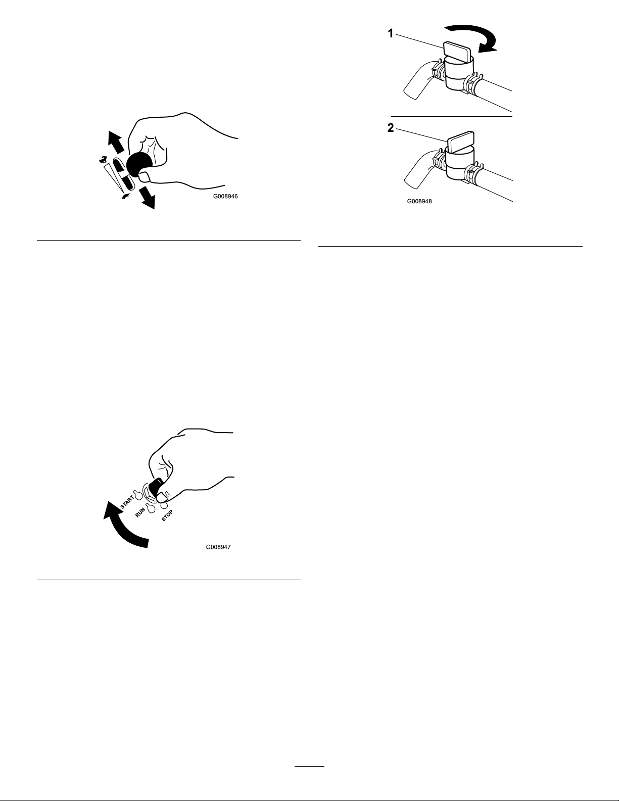
ThethrottlecontrolcanbemovedbetweenFastandSlow
positions(Figure15).
Alwaysusethefastpositionwhenturningonthemowerdeck
withtheblade-controlswitch(PTO).
Figure15
OperatingtheIgnitionSwitch
1.TurntheignitionkeytotheStartposition(Figure16).
Whentheenginestarts,releasethekey.
Important:Donotengagethestarterformore
than5secondsatatime.Iftheenginefailsto
start,allowa15secondcool-downperiodbetween
attempts.Failuretofollowtheseinstructionscan
burnoutthestartermotor.
Note:Additionalstartingcyclesmayberequired
whenstartingtheengineforthersttimeafterthefuel
systemhasbeencompletelywithoutfuel.
Figure17
1.On2.Off
StartingandStoppingthe Engine
StartingtheEngine
1.RaisetheROPSupandlockintoplace,sitontheseat
andfastentheseatbelt.
2.Movethemotioncontrolstoneutral-lockedposition.
3.Settheparkingbrake;refertoSettingtheParking
Brake.
4.Movetheblade-controlswitch(PTO)totheOff
position(Figure18).
5.MovethethrottlelevermidwaybetweentheSlowand
Fastpositions.
Figure16
2.Tostoptheengine,turntheignitionkeytothestop
position.
UsingtheFuel-ShutoffValve
Thefuel-shutoffvalveislocatedundertheseat.Movethe
seatforwardtoaccessit.
Closethefuel-shutoffvalvefortransport,maintenance,and
storage.
Ensurethatthefuel-shutoffvalveisopenwhenstartingthe
engine.
19
Page 20
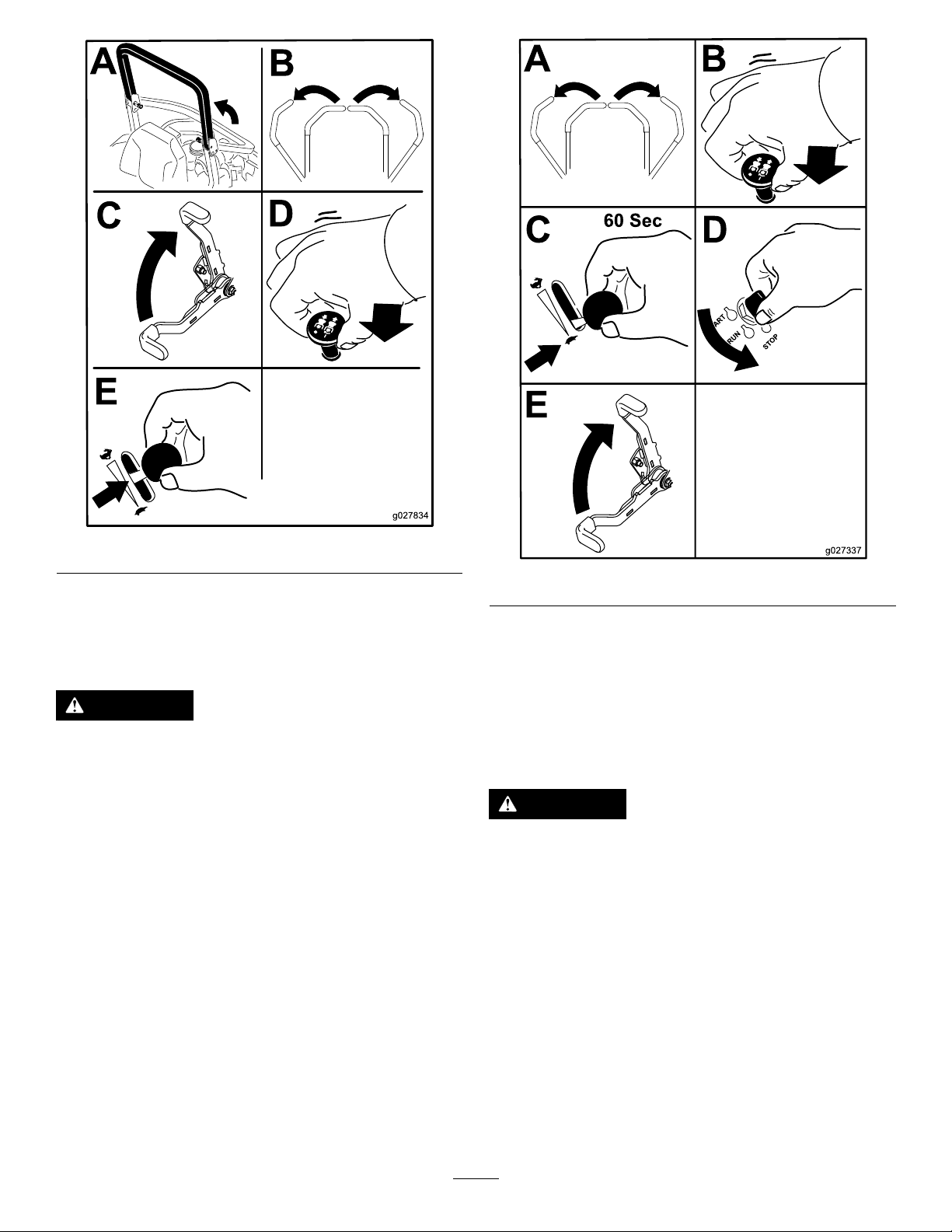
Figure18
g027337
A B
C D
E
6.TurntheignitionkeytotheStartposition(Figure16).
Whentheenginestarts,releasethekey.
StoppingtheEngine
CAUTION
Figure19
Important:Makesurethatthefuelshutoffvalveis
closedbeforetransportingorstoringthemachine,as
fuelleakagemayoccur.Settheparkingbrakebefore
transporting.Makesuretoremovethekeyasthefuel
pumpmayrunandcausethebatterytolosecharge.
Childrenorbystandersmaybeinjuredifthey
moveorattempttooperatethemachinewhileitis
unattended.
Alwaysremovetheignitionkeyandsettheparking
brakewhenleavingthemachineunattended,even
ifjustforafewminutes.
Lettheengineidleatslowthrottle(turtle)for60seconds
beforeturningtheignitionswitchoff.
TheSafety-InterlockSystem
CAUTION
Ifsafety-interlockswitchesaredisconnectedor
damagedthemachinecouldoperateunexpectedly
causingpersonalinjury.
•Donottamperwiththeinterlockswitches.
•Checktheoperationoftheinterlockswitches
dailyandreplaceanydamagedswitchesbefore
operatingthemachine.
UnderstandingtheSafety-Interlock
System
Thesafety-interlocksystemisdesignedtopreventtheengine
fromstartingunless:
•Theparkingbrakeisengaged.
20
Page 21
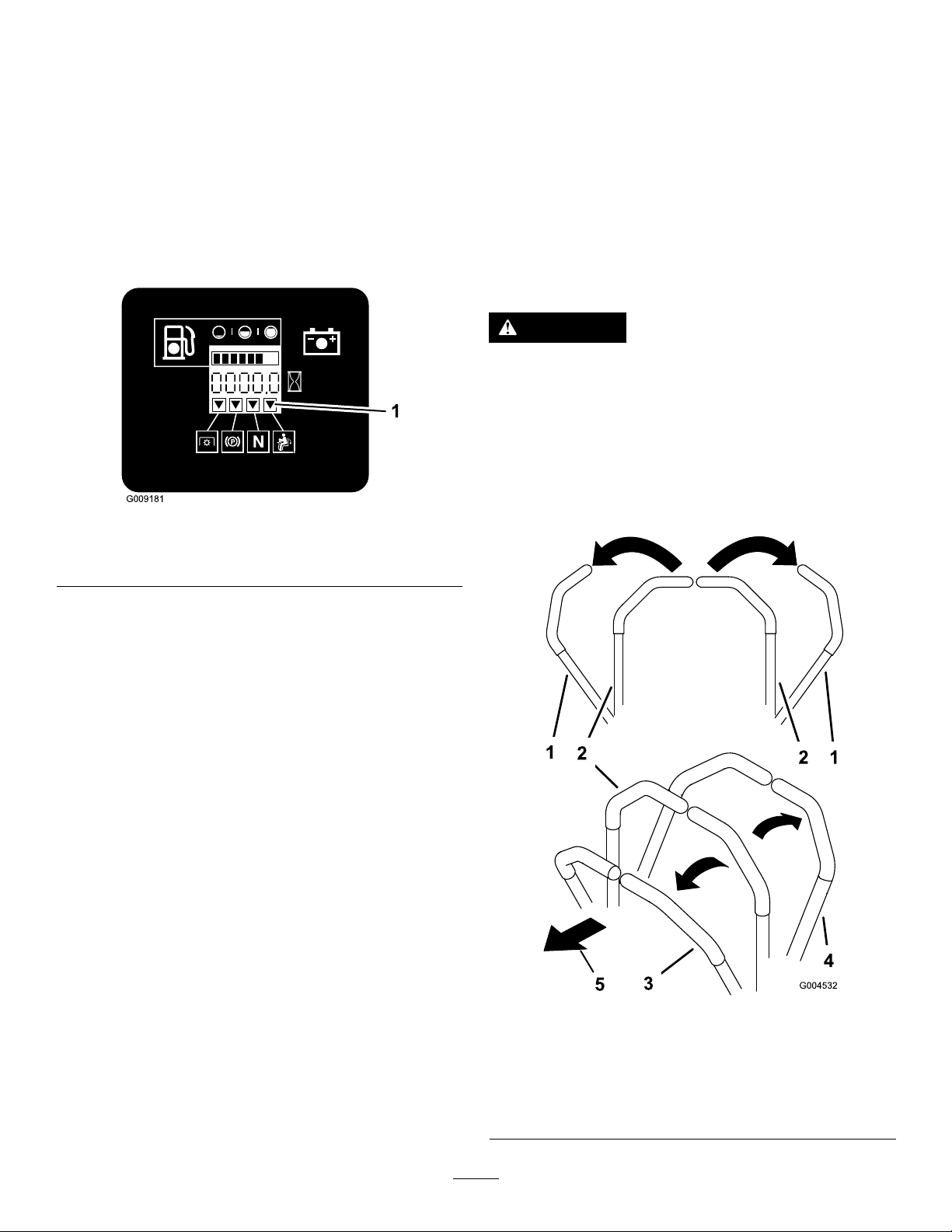
•Theblade-controlswitch(PTO)isdisengaged.
G009181
1
•Themotion-controlleversareintheneutral-locked
position
Thesafety-interlocksystemalsoisdesignedtostopthe
enginewhenthetractioncontrolsaremovedfromthelocked
positionwiththeparkingbrakeengagedorifyourisefrom
theseatwhenthePTOisengaged.
Thehourmeterhassymbolstonotifytheuserwhenthe
interlockcomponentisinthecorrectposition.Whenthe
componentisinthecorrectposition,atrianglewilllightup
inthecorrespondingsquare.
theengineshouldstop.Repeatforothermotion
control.
5.Sittingontheseat,disengagetheparkingbrake,move
theblade-controlswitch(PTO)tooffandmovethe
motion-controlleverstoneutrallockposition.Try
startingtheengine;theengineshouldnotcrank.
DrivingForwardorBackward
Thethrottlecontrolregulatestheenginespeedasmeasured
inrpm(revolutionsperminute).Placethethrottlecontrolin
thefastpositionforbestperformance.Alwaysoperateinthe
fullthrottlepositionwhenmowing.
CAUTION
Machinecanspinveryrapidly.Operatormaylose
controlofmachineandcausepersonalinjuryor
damagetomachine.
•Usecautionwhenmakingturns.
•Slowthemachinedownbeforemakingsharp
turns.
Figure20
1.Triangleslightupwhentheinterlockcomponentsareinthe
correctposition
TestingtheSafety-InterlockSystem
ServiceInterval:Beforeeachuseordaily
Testthesafety-interlocksystembeforeyouusethemachine
eachtime.Ifthesafetysystemdoesnotoperateasdescribed
below,haveanAuthorizedServiceDealerrepairthesafety
systemimmediately.
1.Sittingontheseat,engagetheparkingbrakeandmove
theblade-controlswitch(PTO)toon.Trystartingthe
engine;theengineshouldnotcrank.
2.Sittingontheseat,engagetheparkingbrakeandmove
theblade-controlswitch(PTO)tooff.Moveeither
motion-controllever(outofneutral-lockedposition).
Trystartingtheengine;theengineshouldnotcrank.
Repeatforothercontrollever.
3.Sittingontheseat,engagetheparkingbrake,move
theblade-controlswitch(PTO)tooffandmovethe
motion-controlleverstoneutrallockposition.Now
starttheengine.Whiletheengineisrunning,releasethe
parkingbrake,engagetheblade-controlswitch(PTO)
andriseslightlyfromtheseat;theengineshouldstop.
4.Sittingontheseat,engagetheparkingbrake,move
theblade-controlswitch(PTO)tooffandmovethe
motion-controlleverstoneutrallockposition.Now
starttheengine.Whiletheengineisrunning,center
eithermotioncontrolandmove(forwardorreverse);
UsingtheMotion-ControlLevers
Figure21
1.motion-control
lever—neutral-lock
position
2.Center,unlockedposition5.Frontofmachine
3.Forward
4.Backward
21
Page 22
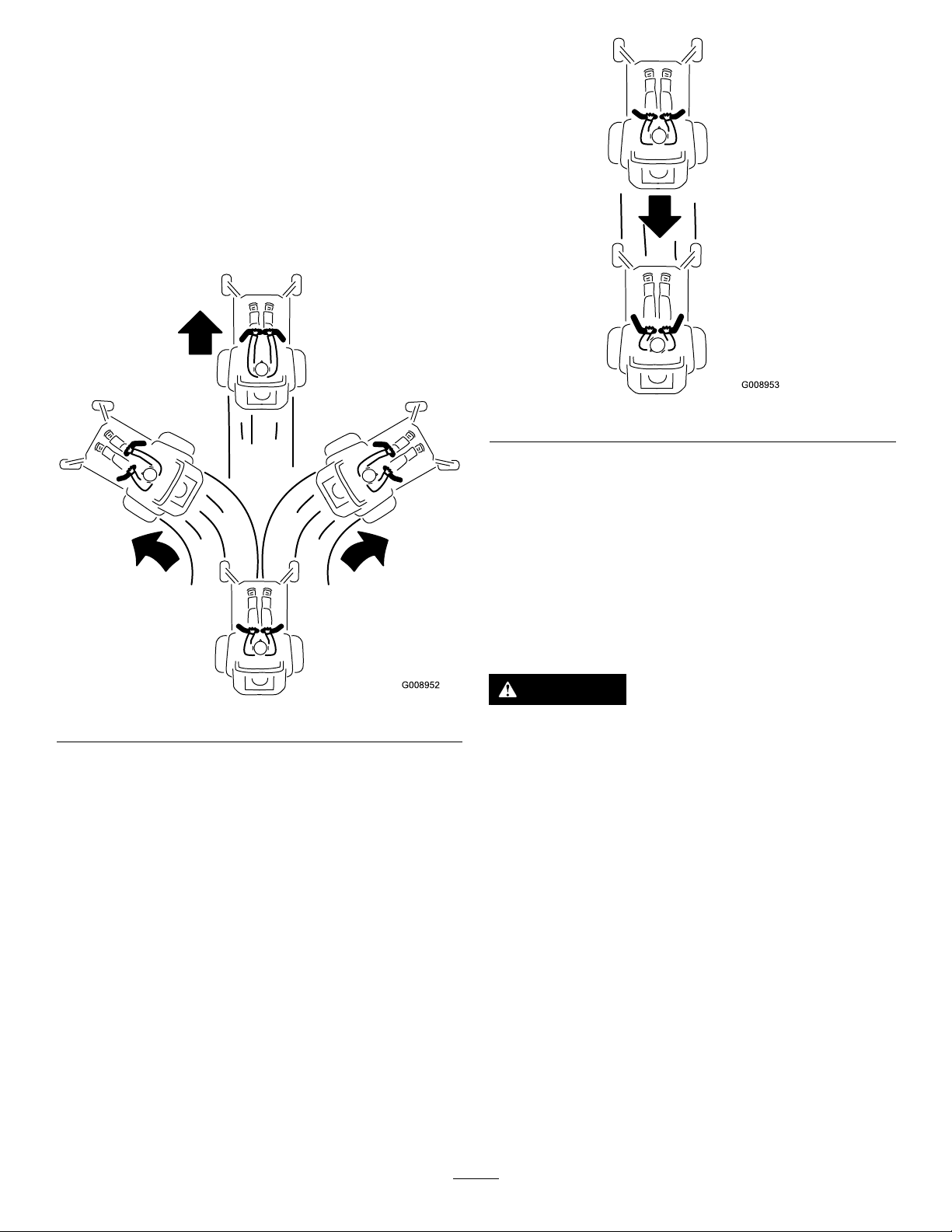
DrivingForward
G008952
G008953
Note:Theenginewillkillifthetractioncontrolleversare
movedwiththeparkingbrakeengaged.
Tostop,pullthemotion-controlleverstotheneutralposition.
1.Releasetheparkingbrake;refertoReleasingthe
ParkingBrakeinOperation.
2.Movetheleverstothecenter,unlockedposition.
3.Togoforward,slowlypushthemotion-controllevers
forward(Figure22).
Figure23
StoppingtheMachine
Figure22
DrivingBackward
1.Movetheleverstothecenter,unlockedposition.
2.Togobackward,lookbehindandslowlypullthe
motion-controlleversrearward(Figure23).
Tostopthemachine,movethetractioncontrolleversto
neutralandtothelockedposition,disengagethepower
take-off(blade-controlswitch(PTO),andturntheignition
keytooff.
Settheparkingbrakewhenyouleavethemachine;referto
SettingtheParkingBrakeinOperation.Remembertoremove
thekeyfromtheignitionswitch.
CAUTION
Childrenorbystandersmaybeinjuredifthey
moveorattempttooperatethemachinewhileitis
unattended.
Alwaysremovetheignitionkeyandsettheparking
brakewhenleavingthemachineunattended,even
ifjustforafewminutes.
AdjustingtheHeightofCut
UsingtheTransportLock
Thetransportlockhas2positionsandisusedwiththedeck
liftpedal.Thereisalockpositionandanunlockpositionfor
thetransportposition.Thetransportlockisusedwiththe
deckliftpedal.RefertoFigure24
22
Page 23
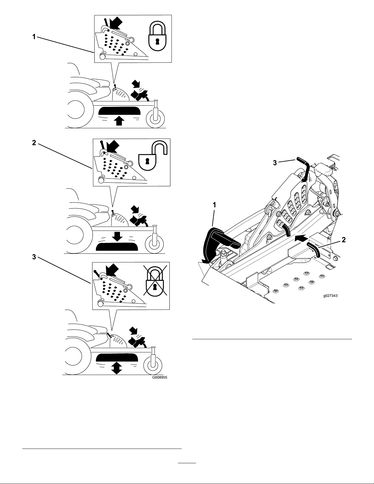
AdjustingtheHeight-of-CutPin
Theheightofcutisadjustedfrom25to140mm(1to
5-1/2inches)in6mm(1/4inch)incrementsbymovingthe
clevispinintodifferentholelocations.
1.Movethetransportlocktothelockposition.
2.Pushonthedeckliftpedalwithyourfoot,andraisethe
mowerdecktothetransportposition(alsothe140mm
(5-1/2inch)cutting-heightposition);refertoFigure25.
3.Toadjust,rotatethepin90degreesandremovethepin
fromtheheight-of-cutbracket(Figure25).
4.Selectaholeintheheight-of-cutbracketcorresponding
totheheightofcutdesired,andinsertthepin(Figure
25).
5.Pushonthedecklift,pullbackonthetransportlock,
andslowlylowerthemowerdeck.
Figure24
Transportlockpositions
1.Transportlock3.Unlockposition—doesnot
lockthemowerdeckinto
transportposition
2.Lockposition—mower
deckwilllockintotransport
position
Figure25
1.Deckliftpedal
2.Height-of-cutpin
3.Transportlock
AdjustingtheAnti-Scalp Rollers
Wheneveryouchangetheheightofcut,itisrecommendedto
adjusttheheightoftheanti-scalprollers.
1.Disengagetheblade-controlswitch(PTO),movethe
motion-controlleverstotheneutral-lockedposition,
andsettheparkingbrake.
2.Stoptheengine,removethekey,andwaitforallmoving
partstostopbeforeleavingtheoperatingposition.
23
Page 24
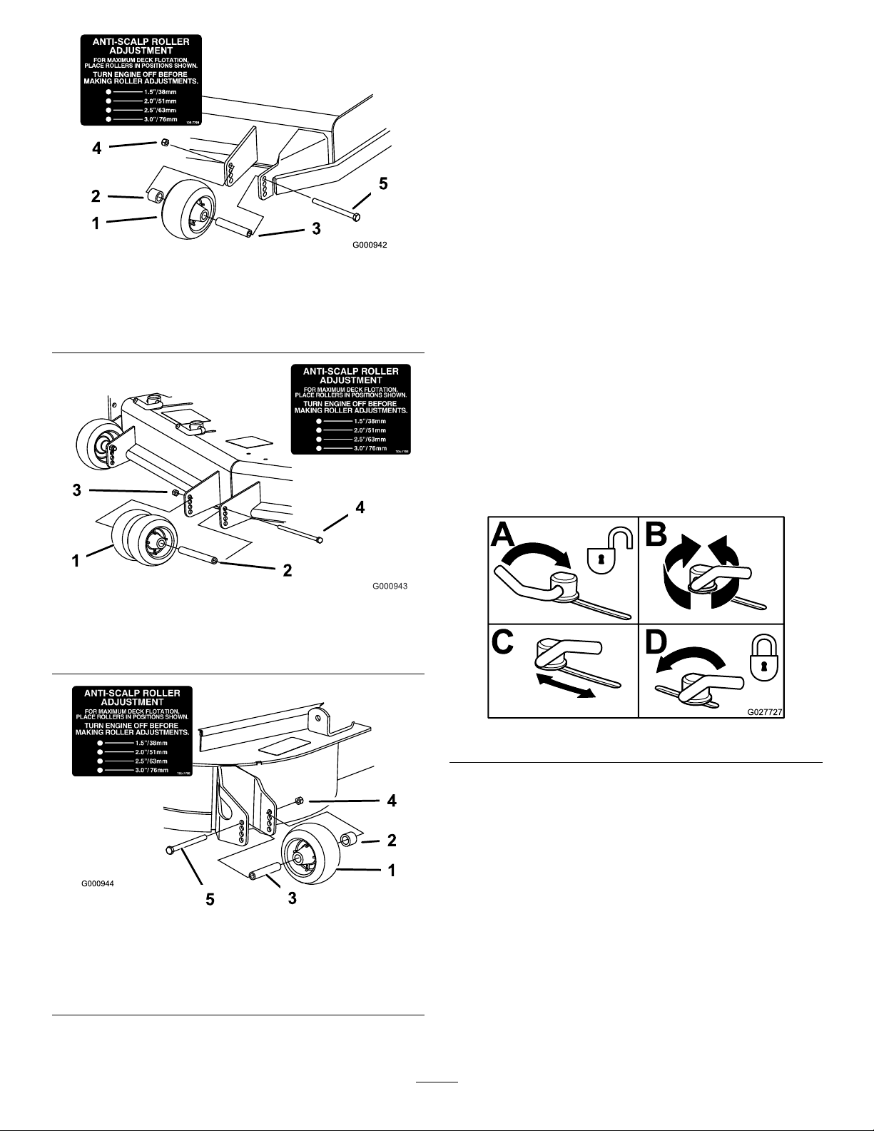
Figure26
1.Anti-scalproller4.Flangenut
2.Spacer
3.Bushing
5.Bolt
AdjustingtheFlowBafeCam
Locks
Thisprocedureisapplicableonlytomachineswiththeow
bafelocks.Certainmodelswillhavenutsandboltsin-place
oftheowbafelocksandcanbeadjustedthesame.
Themowerdischargeowcanbeadjustedfordifferenttypes
ofmowingconditions.Positionthecamlocksandbafeto
givethebestqualityofcut.
1.Disengagetheblade-controlswitch(PTO),movethe
motion-controlleverstotheneutral-lockedposition
andsettheparkingbrake.
2.Stoptheengine,removethekey,andwaitforallmoving
partstostopbeforeleavingtheoperatingposition.
3.Toadjustthecamlocks,swingtheleveruptoloosen
thecamlock(Figure29).
4.Adjustthebafeandcamlocksintheslotstothe
desireddischargeow.
5.Swingtheleverbackovertotightenthebafeandcam
locks(Figure29).
6.Ifthecamlocksdonotlockthebafeintoplaceorit
istootight,loosentheleverandthenrotatethecam
lock.Adjustthecamlockuntilthedesiredlocking
pressureisachieved.
Figure27
1.Anti-scalproller3.Flangenut
2.Bushing4.Bolt
Figure28
1.Anti-scalproller4.Flangenut
2.Spacer
3.Bushing
5.Bolt
Figure29
PositioningtheFlowBafe
Thefollowingguresareonlyrecommendationsforuse.
Adjustmentswillvarybygrasstype,moisturecontent,and
heightofgrass.
Note:Iftheenginepowerdrawsdownandthemower
groundspeedisthesame,openupthebafe.
PositionA
Thisisthefullrearposition.Thesuggesteduseforthis
positionisasfollows.
•Useforshort,lightgrass-mowingconditions.
•Useindryconditions.
24
Page 25
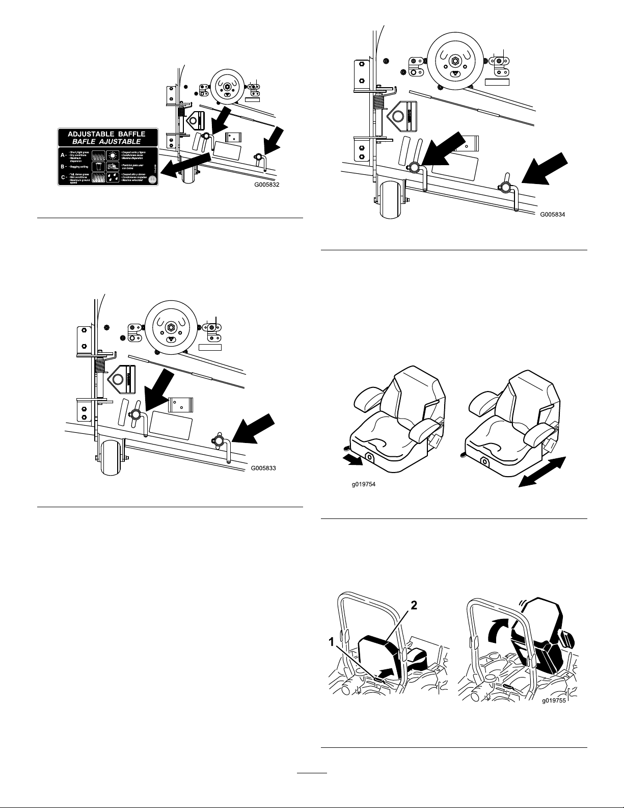
•Forsmallergrassclippings.
g019754
g019755
•Propelsgrassclippingsfartherawayfromthemower.
Figure30
PositionB
Usethispositionwhenbagging.Alwaysalignitwiththe
bloweropening.
Figure32
PositioningtheSeat
Theseatcanmoveforwardandbackward.Positiontheseat
whereyouhavethebestcontrolofthemachineandaremost
comfortable.
Figure31
PositionC
Thisisthefullopenposition.Thesuggesteduseforthis
positionisasfollows.
•Useintall,densegrass-mowingconditions.
•Useinwetconditions.
•Lowerstheenginepowerconsumption.
Toadjusttheseat,movetheleversidewaystounlockseatand
thenmovetheseatforwardorbackward(Figure33).
Figure33
UnlatchingtheSeat
Note:Certainmodelshaveaxedseatthatdoesnotpivot
upward.
•Allowsincreasedgroundspeedinheavyconditions.
•ThispositionissimilartothebenetsoftheToroSFS
mower.
Figure34
1.Seatlatch2.Seat
25
Page 26
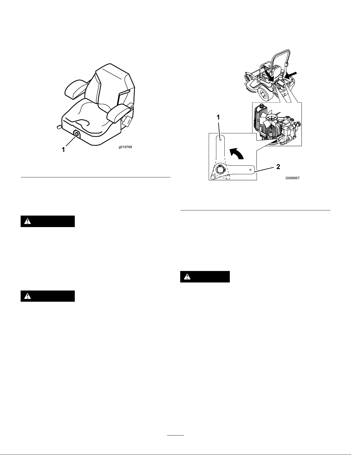
ChangingtheSeatSuspension
g019768
1
Theseatisadjustabletoprovideasmoothandcomfortable
ride.Positiontheseatwhereyouaremostcomfortable.
Toadjustit,turntheknobinfronteitherdirectiontoprovide
thebestcomfort(Figure35).
Figure35
1.Seatsuspensionknob
2.Rotatethereleasevalveleversverticallytopushthe
machine.Thisallowshydraulicoiltoby-passthepump
enablingthewheelstoturn(Figure36).
3.Disengageparkingbrakebeforepushing.
UsingtheDriveWheelRelease Valves
WARNING
Handsmaybecomeentangledintherotatingdrive
componentsbelowtheenginedeck,whichcould
resultinseriousinjury.
Stoptheengine,removethekey,andallowall
movingpartstostopbeforeaccessingthedrive
wheelreleasevalves.
WARNING
Theengineandhydraulicdriveunitscanbecome
veryhot.T ouchingahotengineorhydraulicdrive
unitscancausesevereburns.
Allowtheengineandhydraulicdriveunitstocool
completelybeforeaccessingthedrivewheelrelease
valves.
Thedrivewheelreleasevalvesarelocatedinthebackofeach
hydraulicdriveunit,undertheseat.
Note:Makesurethereleasevalvesareinthefullyhorizontal
positionwhenoperatingthemachineorseveredamagetothe
hydraulicsystemcanoccur.
1.DisengagethePTO(blade-controlswitch)andturnthe
ignitionkeytooff.Movetheleverstoneutral-locked
positionandapplyparkingbrake.Removethekey.
Figure36
1.Verticaltopushthe
machine
4.Rotatethereleasevalvelevershorizontallytorunthe
machine(Figure36).
2.Horizontaltorunthe
machine
UsingtheSideDischarge
Themowerhasahingedgrassdeectorthatdisperses
clippingstothesideanddowntowardtheturf.
DANGER
Withoutagrassdeector,dischargecover,or
completegrasscatcherassemblymountedin
place,youandothersareexposedtobladecontact
andthrowndebris.Contactwithrotatingmower
blade(s)andthrowndebriswillcauseinjuryor
death.
•Neverremovethegrassdeectorfromthemower
becausethegrassdeectorroutesmaterialdown
towardtheturf.Ifthegrassdeectorisever
damaged,replaceitimmediately .
•Neverputyourhandsorfeetunderthemower.
•Nevertrytoclearthedischargeareaormower
bladesunlessyoumovethepowertakeoff
(blade-controlswitch(PTO)totheoffposition,
rotatetheignitionkeytooffandremovethekey .
•Makesurethegrassdeectorisinthedown
position.
26
Page 27
TransportingtheMachine
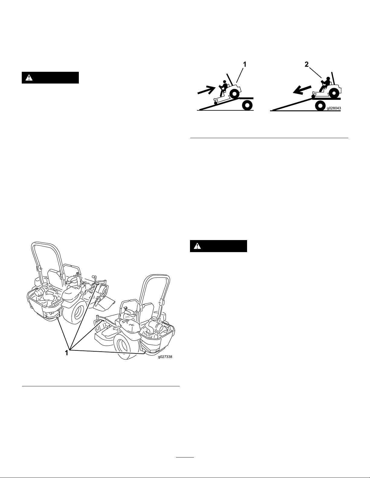
g027338
g028043
LoadingtheMachine
Useaheavy-dutytrailerortrucktotransportthemachine.
Ensurethatthetrailerortruckhasallnecessarybrakes,
lighting,andmarkingasrequiredbylaw .Pleasecarefullyread
allthesafetyinstructions.Knowingthisinformationcould
helpyou,yourfamily,pets,orbystandersavoidinjury.
WARNING
Drivingonthestreetorroadwaywithoutturn
signals,lights,reectivemarkings,oraslow-moving
vehicleemblemisdangerousandcanleadto
accidentscausingpersonalinjury.
Donotdrivethemachineonapublicstreetor
roadway.
Totransportthemachine:
1.Ifusingatrailer,connectittothetowingvehicleand
connectthesafetychains.
2.Ifapplicable,connectthetrailerbrakes.
3.Loadthemachineontothetrailerortruck.
4.Stoptheengine,removethekey,setthebrake,and
closethefuelvalve.
5.Usethemetaltie-downloopsonthemachineto
securelyfastenthemachinetothetrailerortruckwith
straps,chains,cable,orropes(Figure37).
Useextremecautionwhenloadingorunloadingmachines
ontoatraileroratruck.Useafull-widthrampthatiswider
thanthemachineforthisprocedure.Backuprampsand
driveforwarddownramps(Figure38).
Figure38
1.Backupramps
Important:Donotusenarrowindividualrampsfor
eachsideofthemachine.
Ensuretherampislongenoughsothattheanglewiththe
grounddoesnotexceed15degrees(Figure39).Onat
ground,thisrequiresaramptobeatleastfourtimes(4X)as
longastheheightofthetrailerortruckbedtotheground.A
steeperanglemaycausemowercomponentstogetcaughtas
theunitmovesfromtheramptothetrailerortruck.Steeper
anglesmayalsocausethemachinetotiporlosecontrol.If
loadingonornearaslope,positionthetrailerortrucksothat
itisonthedownsideoftheslopeandtherampextendsup
theslope.Thiswillminimizetherampangle.
2.Driveforwarddownramps
1.Tie-downloops
Figure37
WARNING
Loadingamachineontoatrailerortruckincreases
thepossibilityoftip-overandcouldcauseserious
injuryordeath.
•Useextremecautionwhenoperatingamachine
onaramp.
•EnsurethattheROPSisintheuppositionand
usetheseatbeltwhenloadingorunloadingthe
machine.EnsurethattheROPSwillclearthe
topofanenclosedtrailer.
•Useonlyafull-widthramp;donotuseindividual
rampsforeachsideofthemachine.
•Donotexceeda15-degreeanglebetweenthe
rampandthegroundorbetweentherampand
thetrailerortruck.
•Ensurethelengthoframpisatleastfourtimes
(4X)aslongastheheightofthetrailerortruck
bedtotheground.Thiswillensurethatramp
angledoesnotexceed15degreesonatground.
•Backuprampsanddriveforwarddownramps.
•Avoidsuddenaccelerationordecelerationwhile
drivingthemachineonarampasthiscould
causealossofcontroloratip-oversituation.
27
Page 28
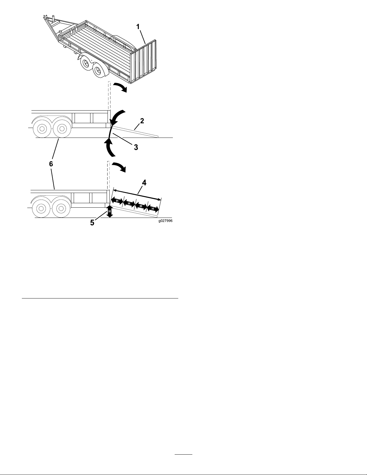
g027996
5
1
2
6
Figure39
1.Full-widthrampinstowed
position
2.Sideviewoffull-width
rampinloadingposition
3.Notgreaterthan
15degrees
4.Rampisatleastfourtimes
(4X)aslongastheheight
ofthetrailerortruckbed
totheground
5.H=heightofthetraileror
truckbedtotheground
6.Trailer
28
Page 29

OperatingTips
FastThrottleSetting
cuttingheighthigherthanusualandcutthegrassatthis
setting.Thencutthegrassagainusingthelower,normal
setting.
Forbestmowingandmaximumaircirculation,operate
theengineatthefastthrottleposition.Airisrequiredto
thoroughlycutgrassclippings,sodonotsettheheight-of-cut
solowastototallysurroundthemowerbyuncutgrass.
Alwaystrytohaveonesideofthemowerfreefromuncut
grass,whichallowsairtobedrawnintothemower.
CuttingaLawnfortheFirstTime
Cutgrassslightlylongerthannormaltoensurethecutting
heightofthemowerdoesnotscalpanyunevenground.
However,thecuttingheightusedinthepastisgenerallythe
bestonetouse.Whencuttinggrasslongerthansixinchestall,
youmaywanttocutthelawntwicetoensureanacceptable
qualityofcut.
Cut1/3oftheGrassBlade
Itisbesttocutonlyabout1/3ofthegrassblade.Cutting
morethanthatisnotrecommendedunlessgrassissparse,or
itislatefallwhengrassgrowsmoreslowly.
MowingDirection
WhenStopping
Ifyoumuststoptheforwardmotionofthemachinewhile
mowing,aclumpofgrassclippingsmaydropontoyourlawn.
Toavoidthis,moveontoapreviouslycutareawiththeblades
engaged.
KeeptheUndersideoftheMowerClean
Cleanclippingsanddirtfromtheundersideofthemower
aftereachuse.Ifgrassanddirtbuildupinsidethemower,
cuttingqualitywilleventuallybecomeunsatisfactory.
BladeMaintenance
Maintainasharpbladethroughoutthecuttingseasonbecause
asharpbladecutscleanlywithouttearingorshreddingthe
grassblades.Tearingandshreddingturnsgrassbrownat
theedges,whichslowsgrowthandincreasesthechanceof
disease.Checkthecutterbladesdailyforsharpness,andfor
anywearordamage.Filedownanynicksandsharpenthe
bladesasnecessary.Ifabladeisdamagedorworn,replaceit
immediatelywithagenuineTOROreplacementblade.
Alternatemowingdirectiontokeepthegrassstanding
straight.Thisalsohelpsdisperseclippingswhichenhances
decompositionandfertilization.
MowatCorrectIntervals
Normally,moweveryfourdays.Butremember,grassgrows
atdifferentratesatdifferenttimes.Sotomaintainthesame
cuttingheight,whichisagoodpractice,mowmoreoftenin
earlyspring.Asthegrassgrowthrateslowsinmidsummer,
mowlessfrequently.Ifyoucannotmowforanextended
period,rstmowatahighcuttingheight;thenmowagain
twodayslateratalowerheightsetting.
CuttingSpeed
Toimprovecutquality,useaslowergroundspeedincertain
conditions.
AvoidCuttingTooLow
Ifthecuttingwidthofthemoweriswiderthanthemower
youpreviouslyused,raisethecuttingheighttoensurethat
uneventurfisnotcuttooshort.
LongGrass
Ifthegrassiseverallowedtogrowslightlylongerthan
normal,orifitcontainsahighdegreeofmoisture,raisethe
29
Page 30

Maintenance
RecommendedMaintenanceSchedule(s)
MaintenanceService
Interval
Aftertherst100hours
Aftertherst250hours
Beforeeachuseordaily
Every50hours
Every100hours
Every150hours
MaintenanceProcedure
•Checkthewheellugnuttorque.
•Checkthewheelhubslotted-nuttorque.
•Checktheparkingbrakeadjustment.
•Changethehydraulicltersandhydraulicoilwhenusinganytypeofoil.
•Checkthesafetysystem.
•Checktheengineoillevel.
•Checktheseatbelt.
•Checktherolloverprotectionsystem(ROPS)knobs.
•Cleantheenginescreenandtheoilcooler.
•Checkandcleanthehydraulicunitshrouds.
•Checkthemowerblades.
•Cleanthemowerdeck.
•Greasethemowerdeckspindlesandidlerarm.
•Checksparkarrester(ifequipped).
•Checkthetirepressure.
•Inspectthebeltsforcracksandwear.
•Checkthehydraulicoillevel.
•Lubricatethemowerdeckliftpivots.
•Changetheengineoil(moreoftenindirtyordustyconditions).
•Checkandcleanenginecoolingnsandshrouds.
•Inspecttheprimarylterandair-inletscreen.
Every200hours
Every250hours
Every300hours
Every500hours
Every600hours
Yearlyorbeforestorage
•Changetheengineoillter.
•Cleantheengineoilcooler.
•Checkandgapthesparkplug.
•Replacethefuellter(moreoftenindirtyordustyconditions).
•ChangethehydraulicltersandhydraulicoilwhenusingMobil®1oil(moreoftenin
dirtyordustyconditions).
•Replacetheprimaryairlter(moreoftenindustyorsandyconditions).
•Checktheinnerairlter.
•Checkthewheellugnuttorque.
•Checkthewheelhubslotted-nuttorque.
•Adjustthecasterpivotbearing.
•Checktheparkingbrakeadjustment.
•ChangethehydraulicltersandhydraulicoilwhenusingT oro®HYPR-OIL™500
hydraulicoil(moreoftenindirtyordustyconditions).
•Replacetheinnerairlter.
Monthly
Yearly
•Checkthebattery.
•Greasethepumpbeltidlerarm.
•Greasethefrontcasterpivots(moreoftenindirtyordustyconditions).
•Repackthefrontcasterwheelbearings(moreoftenindirtyordustyconditions).
•Lubricatethecasterwheelhubs.
•Paintchippedsurfaces.
•Checkallmaintenanceprocedureslistedabovebeforestorage.
Important:Refertoyourengineoperator'smanualforadditionalmaintenanceprocedures.
30
Page 31
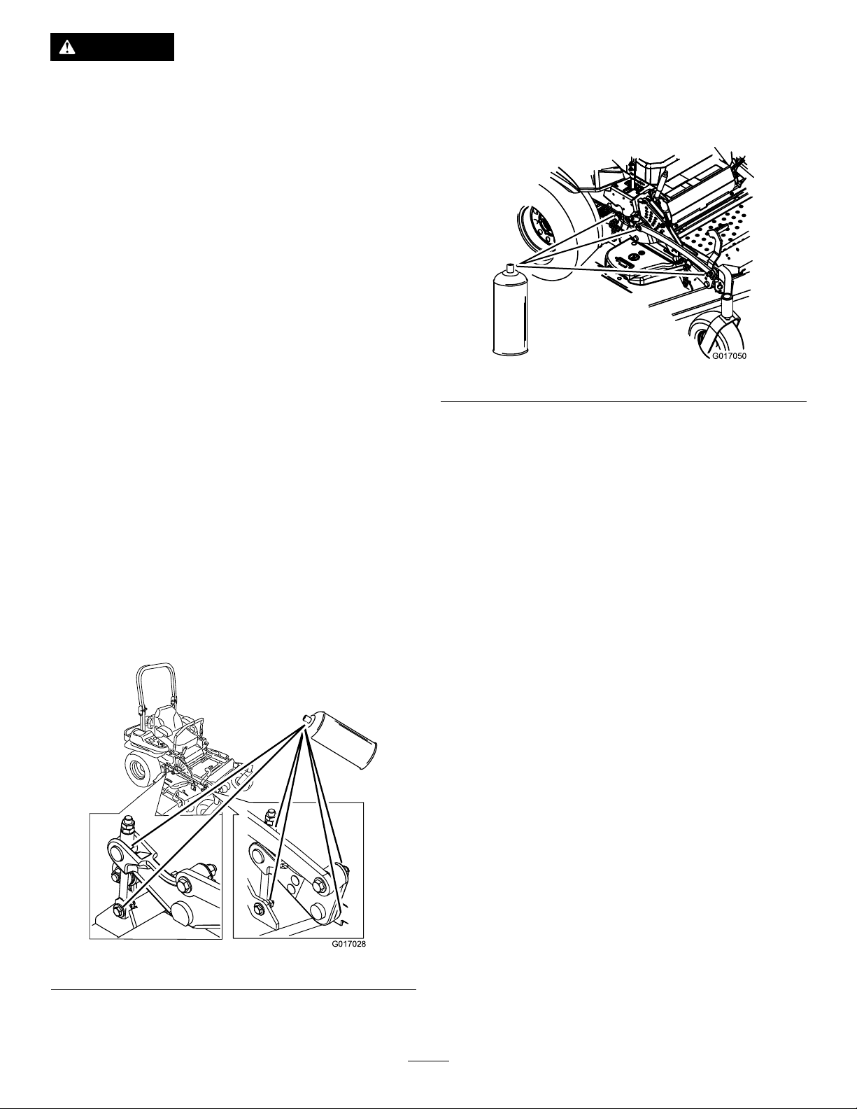
CAUTION
G017028
G017050
Ifyouleavethekeyintheignitionswitch,someonecouldaccidentlystarttheengineandseriouslyinjure
youorotherbystanders.
Removethekeyfromtheignitionbeforeyoudoanymaintenance.
Lubrication
LubricatingtheMachine
Greasemorefrequentlywhenoperatingconditionsare
extremelydustyorsandy.
GreaseType:No.2general-purposelithium-basedor
molybdenum-basedgrease
1.Disengagetheblade-controlswitch(PTO),movethe
motion-controlleverstotheneutral-lockedposition
andsettheparkingbrake.
2.Stoptheengine,removethekey,andwaitforallmoving
partstostopbeforeleavingtheoperatingposition.
Figure41
3.Cleanthegreasettingswitharag.Makesuretoscrape
anypaintoffthefrontofthetting(s).
4.Connectagreaseguntothetting.Pumpgrease
intothettingsuntilgreasebeginstooozeoutofthe
bearings.
5.Wipeupanyexcessgrease.
AddingLightOilorSprayLubrication
ServiceInterval:Every100hours
Lubricatethedeckliftpivots.
GreasingtheMower
ServiceInterval:Every50hours—Greasethemowerdeck
spindlesandidlerarm.
Yearly—Greasethepumpbeltidlerarm.
Yearly—Greasethefrontcasterpivots(moreoftenin
dirtyordustyconditions).
Yearly—Repackthefrontcasterwheelbearings(more
oftenindirtyordustyconditions).
Important:Makesurethatthecuttingunitspindlesare
fullofgreaseweekly.
1.Disengagetheblade-controlswitch(PTO),movethe
motion-controlleverstotheneutral-lockedposition,
andsettheparkingbrake.
2.Stoptheengine,removethekey,andwaitforallmoving
partstostopbeforeleavingtheoperatingposition.
3.Greasethemowerdeckidlerpulleypivotuntilgrease
comeoutthebottom(Figure42).
4.Greasethe3spindlebearingsuntilgreasecomesout
thelowerseals(Figure42).
Figure40
31
Page 32
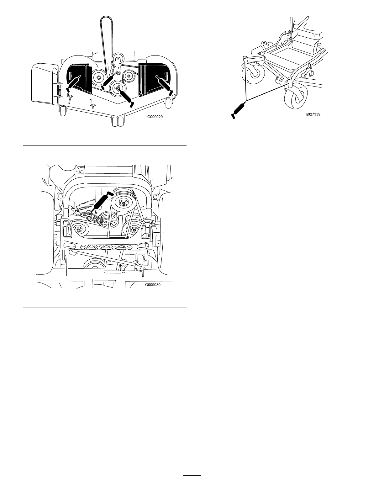
G009029
Figure42
g027339
5.Greasethedrivebeltidlerarm(Figure42).
Figure43
Figure44
6.Removethedustcapandadjustthecasterpivots.
Note:Keepthedustcapoffuntilgreasingiscomplete.
RefertoAdjustingtheCasterPivotBearing(page46).
7.Removethehexplugandthreadagreasettinginto
thehole.
8.Pumpgreaseintothettinguntilitoozesoutaround
thetopbearing.
9.Removethegreasettingfromthehole.
10.Installthehexpluganddustcap(Figure44).
32
Page 33
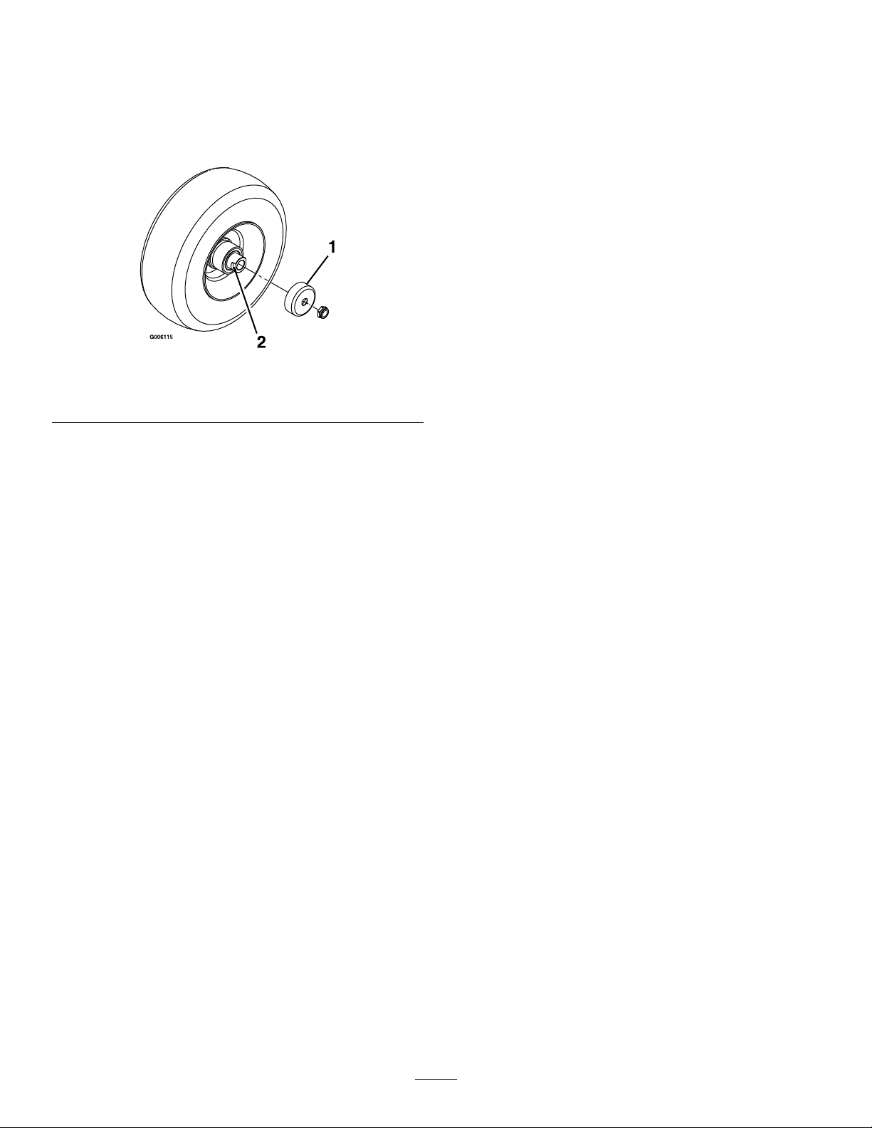
LubricatetheCasterWheel Hubs
13.Applyathreadlockingadhesivetothesecondspacer
nutandthreaditontotheaxlewiththewrenchats
facingoutward.
ServiceInterval:Yearly
1.Stoptheengine,waitforallmovingpartstostop,and
removethekey.Engagetheparkingbrake.
Figure45
1.Sealguard2.Spacernutwithwrench
ats
2.Raisethefrontofthemachineupandsupportitwith
jackstands.
3.Removethecasterwheelfromthecasterforks.
4.Removethesealguardsfromthewheelhub.
14.Torquethenutto8-9N-m(75-80in-lb),loosen,then
re-torqueto2-3N-m(20-25in-lb).
Note:Makesurethattheaxledoesnotextendbeyond
eithernut.
15.Installthesealguardsoverthewheelhubandinsert
thewheelintothecasterfork.Installthecasterbolt
andtightenthenutfully.
Important:Topreventsealandbearingdamage,check
thebearingadjustmentoften.Spinthecastertire.The
tireshouldnotspinfreely(morethan1or2revolutions)
orhaveanysideplay .Ifthewheelspinsfreely,adjustthe
torqueonthespacernutuntilthereisaslightamountof
drag.Applythreadlockingadhesive.
5.Remove1ofthespacernutsfromtheaxleassembly
inthecasterwheel.
Note:Notethatthreadlockingadhesivehasbeen
appliedtolockthespacernutstotheaxle.Remove
theaxle(withtheotherspacernutstillassembledtoit)
fromthewheelassembly.
6.Pryouttheseals,andinspectthebearingsforwearor
damageandreplaceifnecessary.
7.Packthebearingswithageneral-purposegrease.
8.Insert1bearingand1newsealintothewheel.
Note:Thesealsmustbereplaced.
9.Iftheaxleassemblyhashadbothspacernutsremoved
(orbrokenloose),applyathreadlockingadhesiveto1
spacernutandthreaditontotheaxlewiththewrench
atsfacingoutward.
Note:Donotthreadthespacernutalloftheway
ontotheendoftheaxle.Leaveapproximately3mm
(1/8inch)fromtheoutersurfaceofthespacernutto
theendoftheaxleinsidethenut.
10.Inserttheassemblednutandaxleintothewheelonthe
sideofthewheelwiththenewsealandbearing.
11.Withtheopenendofthewheelfacingup,llthearea
insidethewheelaroundtheaxlefullofgeneral-purpose
grease.
12.Insertthesecondbearingandnewsealintothewheel.
33
Page 34
EngineMaintenance
g012996
3
4
1
2
g012997
1
2
3
4
5
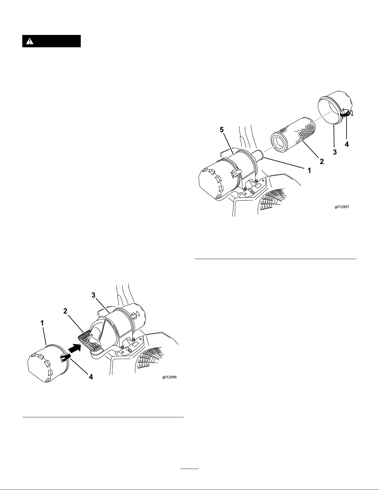
8.Gentlyslidetheprimarylteroutoftheair-cleaner
body(Figure47).
WARNING
Contactwithhotsurfacesmaycausepersonal
injury.
Keephands,feet,face,clothing,andotherbody
partsawaythemuferandotherhotsurfaces.
ServicingtheAirCleaner
ServiceInterval:Every150hours
Every300hours/Y early(whichevercomes
rst)—Replacetheprimaryairlter(moreoftenin
dustyorsandyconditions).
Every300hours—Checktheinnerairlter.
Every600hours—Replacetheinnerairlter.
Note:Checktheltersmorefrequentlyiftheoperating
conditionsareextremelydustyorsandy.
RemovingtheFilters
1.DisengagethePTO,movethemotion-controlleversto
theneutral-lockedposition,andsettheparkingbrake.
2.Stoptheengine,removethekey,andwaitforallmoving
partstostopbeforeleavingtheoperatingposition.
3.Releasethelatchesontheaircleanerandpullthe
air-inletcoverofftheair-cleanerbody(Figure46).
4.Cleantheair-inletscreenandcover.
5.Installtheair-inletcoverandsecureitwiththelatches
(Figure46).
Note:Avoidknockingthelterintothesideofthe
body.
9.Removetheinnerlteronlyifyouintendtoreplaceit.
Important:Neverattempttocleantheinnerlter.
Ifthesafetylterisdirty,thentheprimarylteris
damaged;replacebothlters.
Figure47
1.Innerlter
2.Primarylter
3.Air-cleanercover
10.Inspecttheprimarylterfordamagebylookinginto
thelterwhileshiningabrightlightontheoutsideof
thelter.
4.Latch
5.Air-cleanerbody
Figure46
1.Air-inletcover3.Air-cleanerbody
2.Air-inletscreen4.Latch
6.Releasethelatchesontheaircleanerandpullthe
air-cleanercoverofftheair-cleanerbody(Figure47).
7.Cleantheinsideoftheair-cleanercoverwith
compressedair.
Note:Anyholesinthelterwillappearasbright
spots.Ifthelterisdamaged,discardit.
ServicingthePrimaryFilter
•Iftheprimarylterisdirty,bent,ordamaged,replaceit.
•Donotcleantheprimarylter.
ServicingtheSafetyFilter
Replacethesafetylter,nevercleanit.
Important:Neverattempttocleanthesafetylter.
Ifthesafetylterisdirty,thentheprimarylteris
damaged.Replacebothlters.
InstallingtheFilters
Important:T opreventenginedamage,alwaysoperate
theenginewithbothairltersandcoverinstalled.
1.Ifinstallingnewlters,checkeachlterforshipping
damage.Donotuseadamagedlter.
34
Page 35
2.Iftheinnerlterisbeingreplaced,carefullyslideitinto
g012991
0
0
50
SAE 30
thelterbody(Figure47).
3.Carefullyslidetheprimarylterovertheinnerlter
(Figure47).
Note:Ensurethattheprimarylterisfullyseatedby
pushingonitsouterrimwhileinstallingit.
Important:Donotpressonthesoftinsidearea
ofthelter.
4.Installtheaircleanercoverandsecurethelatches
(Figure47).
ServicingtheEngineOil
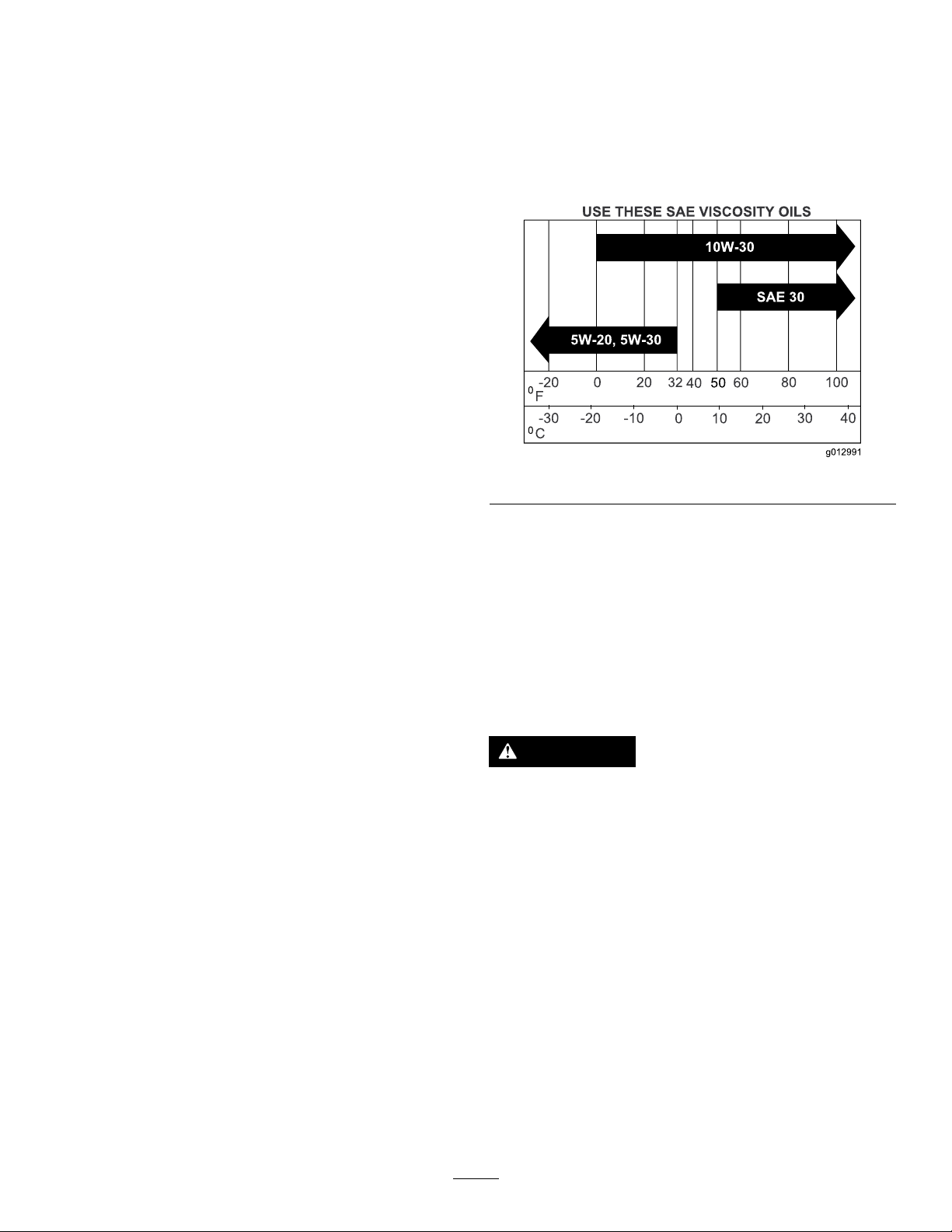
OilType:Detergentoil(APIserviceclassSL,SM,SN,or
higher)
OilCapacity:withalterchange,1.7L(1.8USqt);withno
lterchange,1.4L(1.5USqt)
Viscosity:Seethetablebelow.
Figure48
Note:Useofsyntheticoilhaving5W-20or5W-30ratingis
acceptable,upto4degreesC(40degreesF).
Note:Syntheticoilswillprovidebetterstartinginextreme
coldbelow-23degreesC(-10degreesF).
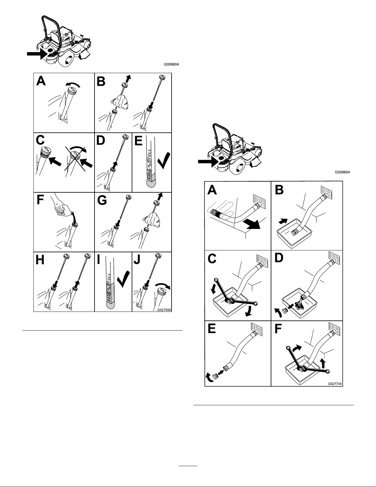
CheckingtheEngine-OilLevel
ServiceInterval:Beforeeachuseordaily
Note:Checktheoilwhentheengineiscold.
WARNING
Contactwithhotsurfacesmaycausepersonal
injury.
Keephands,feet,face,clothingandotherbody
partsawayfromthemuferandotherhotsurfaces.
Important:Donotoverllthecrankcasewithoil
becausedamagetotheenginemayresult.Donotrun
enginewithoilbelowthelowmarkbecausetheengine
maybedamaged.
1.DisengagethePTO,movethemotion-controlleversto
theneutral-lockedpositionandsettheparkingbrake.
2.Stoptheengine,removethekey,andwaitforall
movingpartstostopbeforeleavingtheoperating
35
position(Figure49).
Page 36
G008804
B
A
C
D
E
G027659
F
G
H
I J
ChangingtheEngineOil
G008804
ServiceInterval:Every100hours(moreoftenindirtyor
dustyconditions).
Note:Disposeoftheusedoilatarecyclingcenter.
1.Parkthemachinesothattherearisslightlylowerthan
thefronttoensurethattheoildrainscompletely.
2.DisengagethePTO,movethemotion-controlleversto
theneutral-lockedposition,andsettheparkingbrake.
3.Stoptheengine,removethekey,andwaitforall
movingpartstostopbeforeleavingtheoperating
position(Figure50).
Figure49
Figure50
36
Page 37
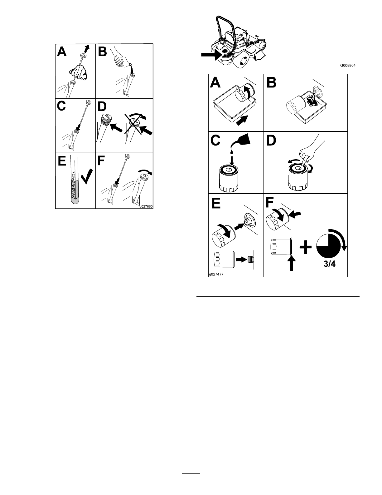
4.Slowlypourapproximately80%ofthespeciedoil
B
A
C
D
E
F
g027660
G008804
B
A
C D
E
F
3/4
g027477
intothellertubeandslowlyaddtheadditionaloilto
bringittotheFullmark(Figure51).
5.Starttheengineanddrivetoaatarea.Checktheoil
levelagain.
ChangingtheEngine-OilFilter
ServiceInterval:Every200hours
Note:Changetheengineoilltermorefrequentlywhen
operatingconditionsareextremelydustyorsandy.
1.Draintheoilfromtheengine;refertoChangingthe
EngineOil(page36).
2.Changetheengineoillter(Figure52).
Figure51
Figure52
Note:Ensuretheoilltergaskettouchestheengine
andthenanextra3/4turniscompleted.
3.Fillthecrankcasewiththepropertypeofnewoil;refer
toChangingtheEngineOil(page36).
ServicingtheEngine-OilCooler
ServiceInterval:Every200hours
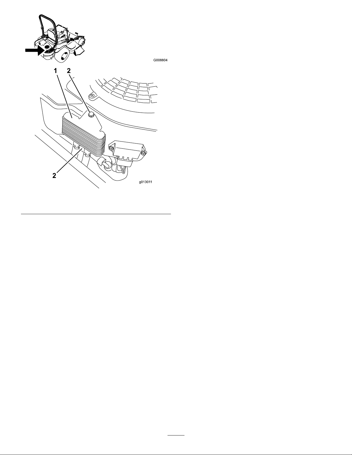
1.Keeptheoilcoolerfreeofdebris.bycleaningthens
withabrush.
2.Removetheboltsholdingtheoilcoolertotheengine
housing.
3.Cleantheinsideoftheoilcoolerwithabrush.
4.Installtheoilcoolertotheenginehousing.
37
Page 38
G008804
g01301 1
1 2
2
ServicingtheSparkPlugs
ServiceInterval:Every200hours—Checkandgapthe
sparkplug.
Makesurethattheairgapbetweenthecenterandside
electrodesiscorrectbeforeinstallingthesparkplugs.Usea
spark-plugwrenchforremovingandinstallingthesparkplugs
andagappingtool/feelergaugetocheckandadjusttheair
gap.Installnewsparkplugsifnecessary.
Figure53
1.Engineoilcooler2.Bolts
Type:Champion
®
XC12YC,Champion
®
Platinum3071
orequivalent
AirGap:0.76mm(0.030inch)
RemovingtheSparkPlugs
1.Stoptheengine,removethekey,andwaitforallmoving
partstostopbeforeleavingtheoperatingposition.
2.DisengagethePTO,movethemotion-controlleversto
theneutral-lockedpositionandsettheparkingbrake.
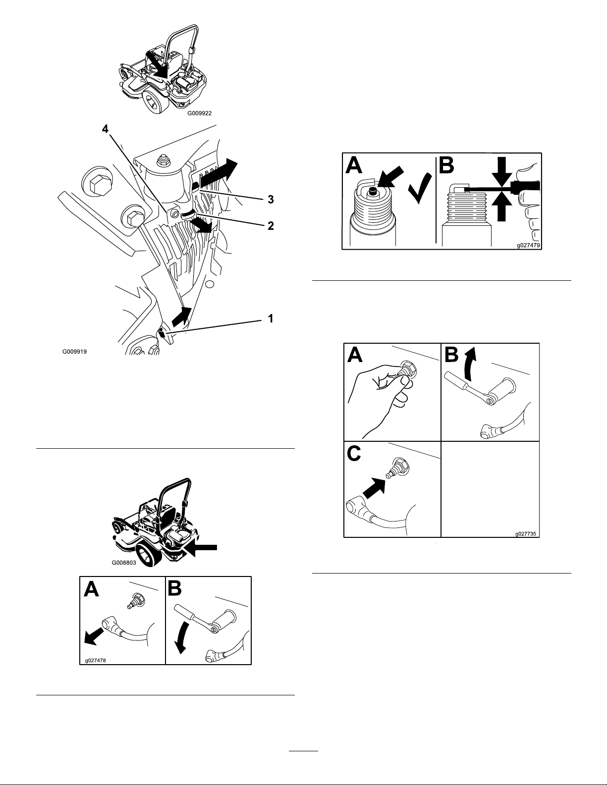
3.Removetheleft-handhydraulicunitshroudinthe
orderlistedwithFigure54.
Note:Thisgivesyouaccesstothefrontsparkplug.
38
Page 39
G008803
B
A
g027478
CheckingtheSparkPlugs
B
A
g027479
Important:Replacethesparkplugswhentheyhave:a
blackcoating,wornelectrodes,anoilylm,cracksor
reuseisquestionable.
Ifyouseelightbrownorgrayontheinsulator,theengineis
operatingproperly .Ablackcoatingontheinsulatorusually
meansthattheaircleanerisdirty.
Setthegapto0.76mm(0.030inch).
Figure56
InstallingtheSparkPlugs
Figure54
1.Pullthistabouttothe
sideinthedirectionofthe
arrow.
2.Pulltheshroudoffofthis
frametabinthedirection
ofthearrow.
4.Removethesparkplugs.
Tightenthesparkplugsto24.4to29.8N-m(18to22ft.-lb).
3.Pulltheshroudoffofthis
frametabinthedirection
ofthearrow.
4.Shroud
Figure57
Figure55
5.Installthelefthandhydraulicunitshroud(Figure54).
39
Page 40

CheckSparkArrester(if equipped)
ServiceInterval:Every50hours
WARNING
Hotexhaustsystemcomponentsmayignite
gasolinevaporsevenaftertheengineisstopped.
Hotparticlesexhaustedduringengineoperation
mayigniteammablematerials.Firemayresultin
personalinjuryorpropertydamage.
FuelSystem
Maintenance
WARNING
Fuelsystemcomponentsareunderhighpressure.
Theuseofimpropercomponentscanresultin
systemfailure,gasolineleakage,andpossible
explosion.
Useonlyapprovedfuellinesandfuellters.
Donotfuelorruntheengineunlesssparkarrester
isinstalled.
1.Stopengine,waitforallmovingpartstostop,and
removekey.Engageparkingbrake.
2.Waitformufertocool.
3.Ifanybreaksinthescreenorweldsareobserved,
replacethearrester.
4.Ifpluggingofthescreenisobserved,removethe
arresterandshakelooseparticlesoutofthearrester
andcleanscreenwithawirebrush(soakinsolventif
necessary).Reinstallarresteronexhaustoutlet.
ServicingtheElectronicFuel InjectionSystem
Thismachinecontainsanelectronicfuelinjectionsystem.It
controlsthefuelowunderdifferentoperatingconditions.
Theelectroniccontrolunit(ECU)continuouslymonitorsthe
operationoftheEFIsystem.
Ifaproblemorfaultwithinthesystemisdetected,the
malfunctionindicatorlight(MIL)isilluminated.TheMILis
theredlightlocatedintherightconsolepanel.
OncetheMILilluminates,initialtroubleshooting
checksshouldbemade.RefertotheMILsectionunder
Troubleshooting.
Ifthesechecksdonotcorrecttheproblem,furtherdiagnosis
andservicingbyanAuthorizedServiceDealerisnecessary.
ReplacingtheLow-Pressure FuelFilter
ServiceInterval:Every200hours/Yearly(whichevercomes
rst)(moreoftenindirtyordusty
conditions).
Thefuellterislocatedneartheengineonthefrontorrear
sideoftheengine.
1.DisengagethePTO,movethemotion-controlleversto
theneutral-lockedposition,andsettheparkingbrake.
2.Stoptheengine,removethekey,andwaitforallmoving
partstostopbeforeleavingtheoperatingposition.
3.Allowthemachinetocooldown.
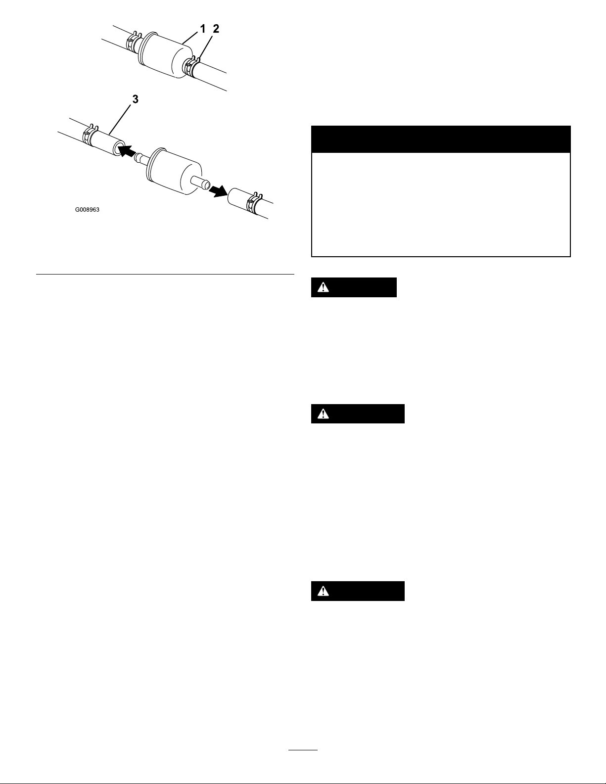
4.Closethefuel-shutoffvalveundertheseat(Figure58).
40
Page 41
G008963
12
3
1.Fuellter
2.Hoseclamp
Figure58
3.Fuelline
ElectricalSystem
Maintenance
ServicingtheBattery
ServiceInterval:Monthly
WARNING
CALIFORNIA
Proposition65Warning
Batteryposts,terminals,andrelated
accessoriescontainleadandleadcompounds,
chemicalsknowntotheStateofCalifornia
tocausecancerandreproductiveharm.
W ash hands after handling .
5.Squeezetheendsofthehoseclampstogetherandslide
themawayfromthelter(Figure58).
6.Removethelterfromthefuellines.
7.Installanewlterandmovethehoseclampscloseto
thelter(Figure58).
8.Openthefuel-shutoffvalve.
Note:Itisimportanttoinstallthefuellinehosesandsecure
themwithplastictiesthesameastheywereoriginallyinstalled
atthefactory,tokeepthefuellineawayfromcomponents
thatcouldcausefuellinedamage.
ServicingtheHigh-Pressure FuelFilter
Donotattempttoservicethehigh-pressurefuellter.The
high-pressurelterisintegratedwithinthefuelpumpmodule.
Thefuellterandothercomponentsinsidethefuelpump
modulearenotserviceable.Donotattempttoopenthefuel
pumpmodule.
EnsurethatanAuthorizedServiceDealerreplacesthefuel
pumpmodulewiththehigh-pressurefuellter.
DANGER
Batteryelectrolytecontainssulfuricacidwhichisa
deadlypoisonandcausessevereburns.
Donotdrinkelectrolyteandavoidcontactwith
skin,eyesorclothing.Wearsafetyglassestoshield
youreyesandrubberglovestoprotectyourhands.
RemovingtheBattery
WARNING
Batteryterminalsormetaltoolscouldshortagainst
metalmachinecomponentscausingsparks.Sparks
cancausethebatterygasestoexplode,resulting
inpersonalinjury.
•Whenremovingorinstallingthebattery,donot
allowthebatteryterminalstotouchanymetal
partsofthemachine.
•Donotallowmetaltoolstoshortbetween
thebatteryterminalsandmetalpartsofthe
machine.
ServicingtheFuelTank
Donotattempttodrainthefueltank.Ensurethatan
AuthorizedServiceDealerdrainsthefueltank.
WARNING
Incorrectbatterycableroutingcoulddamagethe
machineandcablescausingsparks.Sparkscan
causethebatterygasestoexplode,resultingin
personalinjury.
•Alwaysdisconnectthenegative(black)battery
cablebeforedisconnectingthepositive(red)
cable.
•Alwaysconnectthepositive(red)batterycable
beforereconnectingthenegative(black)cable.
41
Page 42
1.Disengagetheblade-controlswitch(PTO),movethe
motion-controlleverstotheneutral-lockedposition
andsettheparkingbrake.
2.Stoptheengine,removethekey,andwaitforallmoving
partstostopbeforeleavingtheoperatingposition.
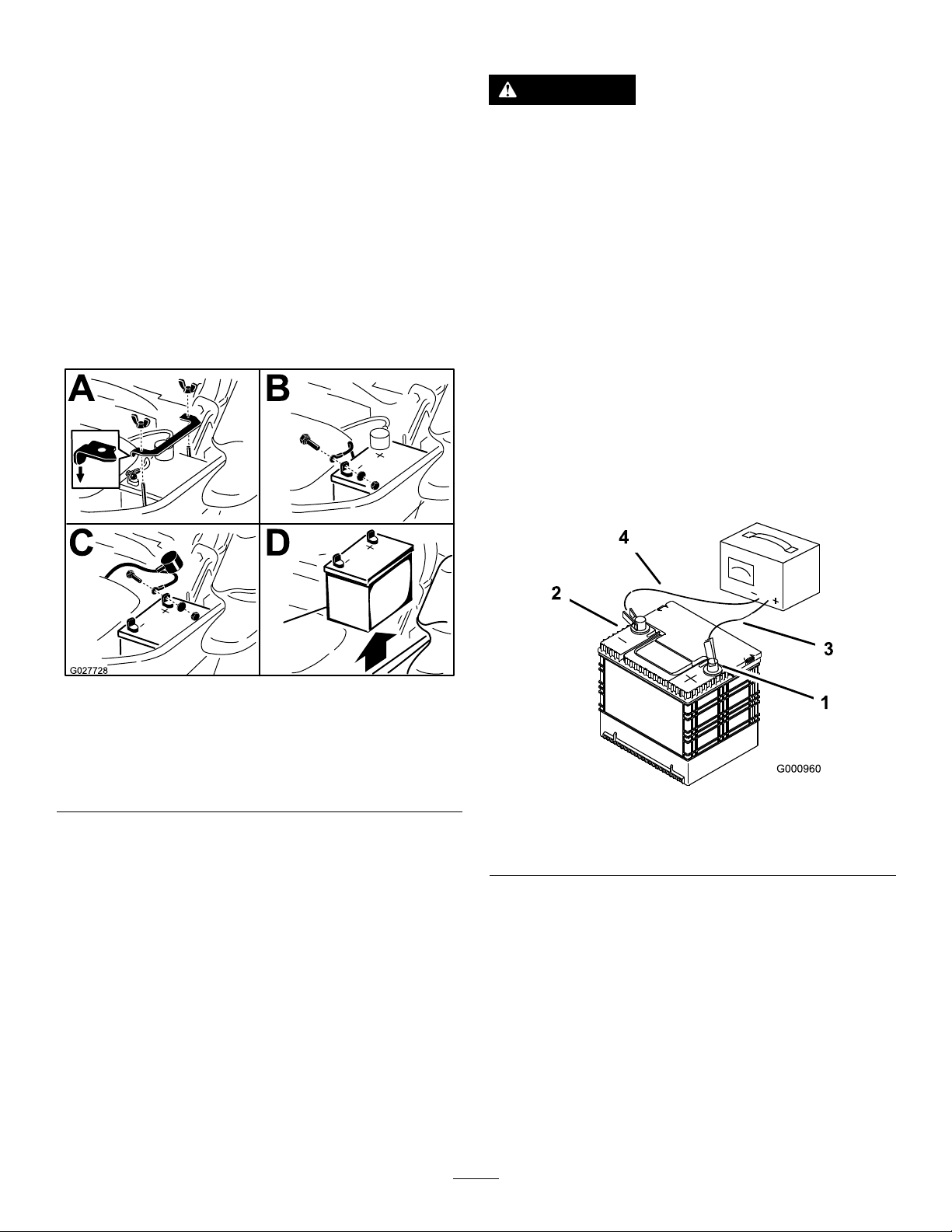
3.Firstdisconnectthenegativebatterycable(black)from
thenegative(-)(black)batteryterminal(Figure59).
4.Slidetheredterminalbootoffthepositive(red)battery
terminalandremovethepositive(+)(red)batterycable
(Figure59).
5.Removethewingnutsecuringthebatteryclamp
(Figure59).
ChargingtheBattery
WARNING
Chargingthebatteryproducesgasesthatcan
explode.
Neversmokenearthebatteryandkeepsparksand
amesawayfrombattery.
Important:Alwayskeepthebatteryfullycharged
(1.265specicgravity).Thisisespeciallyimportantto
preventbatterydamagewhenthetemperatureisbelow
0°C(32°F).
6.Removetheclamp(Figure59).
7.Removethebattery.
Figure59
1.Removethewingnutand
clamp
2.Removethenegative
batterycablebeforethe
positive
1.Chargebatteryfor10to15minutesat25to30amps
or30minutesat10amps.
2.Whenthebatteryisfullycharged,unplugthecharger
fromtheelectricaloutlet;thendisconnectthecharger
leadsfromthebatteryposts(Figure60).
3.Installthebatteryinthemachineandconnectthe
batterycables,refertoInstallingtheBattery.
Note:Donotrunthemachinewiththebattery
disconnected;electricaldamagemayoccur.
3.Removethepositive
batterycable
4.Removebattery
Figure60
InstallingtheBattery
1.Positionbatteryinthetraywiththeterminalposts
oppositefromthehydraulictank(Figure59).
2.First,installthepositive(red)batterycabletopositive
(+)batteryterminal.
3.Theninstallthenegative(black)batterycableand
groundwiretothenegative(-)batteryterminal.
4.Securethecableswith2bolts,2washers,and2locknuts
(Figure59).
5.Slidetheredterminalbootontothepositive(red)
batterypost.
6.Installtheclampandsecureitwiththewingnut(Figure
59).
1.Positivebatterypost
2.Negativebatterypost
42
3.Red(+)chargerlead
4.Black(-)chargerlead
Page 43
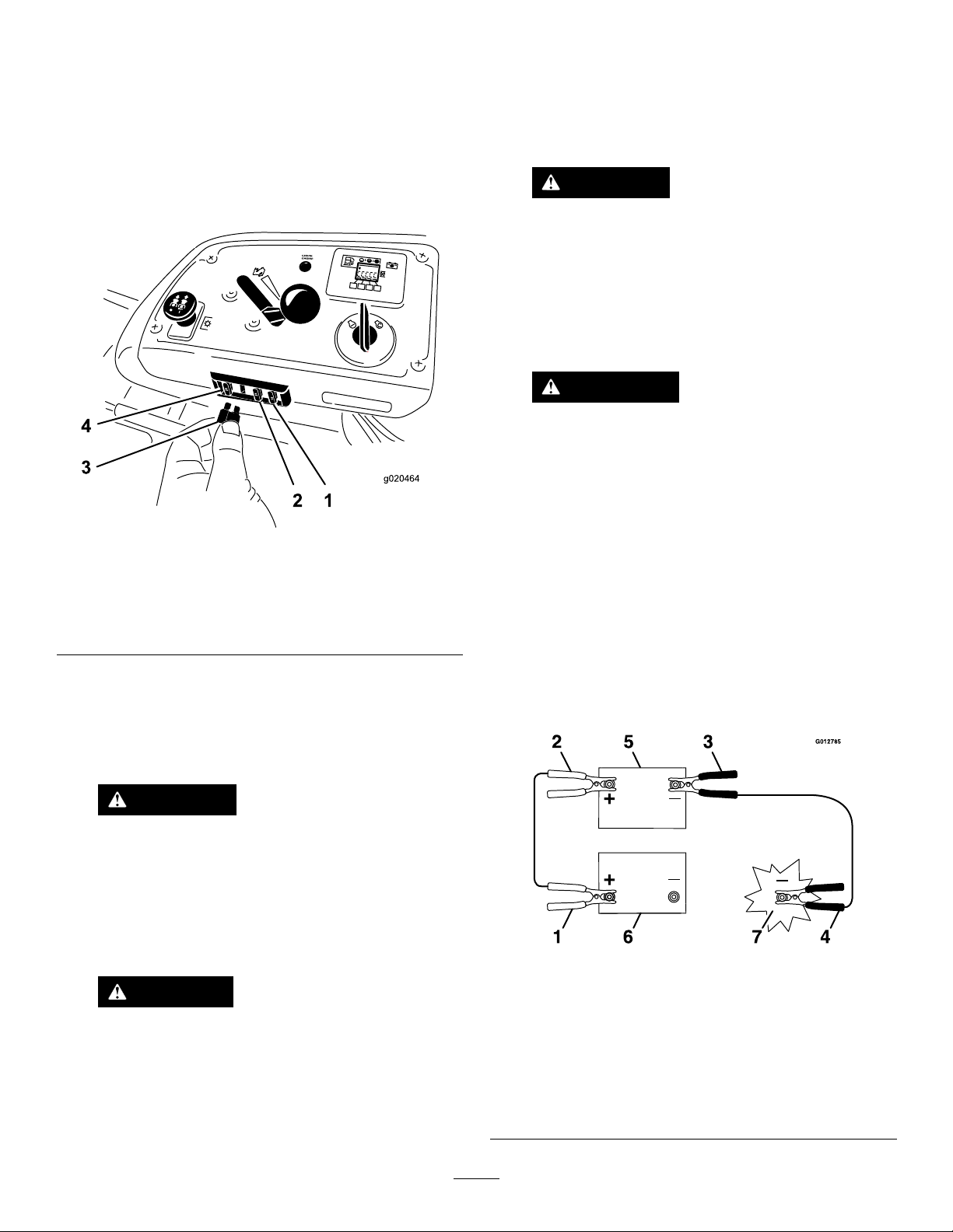
ServicingtheFuses
g020464
Theelectricalsystemisprotectedbyfuses.Itrequires
nomaintenance;however,ifafuseblowscheckthe
component/circuitforamalfunctionorshort.
1.Thefusesarelocatedonrighthandconsolenextto
theseat(Figure61).
2.Toreplacethefuses,pulloutonthefusetoremoveit.
3.Installanewfuse(Figure61).
2.Makesurethattheboosterbatteryisagoodandfully
chargedlead-acidbatteryat12.6voltsorgreater.Use
properlysizedjumpercableswithshortlengthsto
reducevoltagedropbetweensystems.Makesurethat
thecablesarecolorcodedorlabeledforthecorrect
polarity.
CAUTION
Connectingthejumpercablesincorrectly
(wrongpolarity)canimmediatelydamagethe
EFIsystem.
Becertainofbatteryterminalpolarityand
jumpercablepolaritywhenhookingup
batteries.
WARNING
Batteriescontainacidandproduceexplosive
gases.
•Shieldtheeyesandfacefromthebatteries
atalltimes.
Figure61
1.Optional
accesory—15amp
2.Charge—25amp5.Console
3.PTO—10amp
4.Main—25amp
Jump-StartingtheMachine
1.Checkandcleancorrosionfromthebatteryterminals
beforejump-starting.Ensurethattheconnectionsare
tight.
CAUTION
Corrosionorlooseconnectionscancause
unwantedelectricalvoltagespikesatanytime
duringthejump-startingprocedure.
Donotattempttojump-startwithlooseor
corrodedbatteryterminals,ordamagetothe
engineorEFImayoccur.
•Donotleanoverthebatteries.
Note:Besuretheventcapsaretightandlevel.Place
adampcloth,ifavailable,overanyventcapsonboth
batteries.Besurethevehiclesdonottouchandthat
bothelectricalsystemsareoffandatthesamerated
systemvoltage.Theseinstructionsarefornegative
groundsystemsonly .
3.Connectthepositive(+)cabletothepositive(+)
terminalofthedischargedbatterythatiswiredtothe
starterorsolenoidasshowninFigure62.
Figure62
DANGER
Jump-startingaweakbatterythatiscracked
orfrozen,orhasalowelectrolytelevelor
anopen/shortedbatterycellcancausean
explosionresultinginseriouspersonalinjury.
Donotjump-startaweakbatteryifthese
conditionsexist.
1.Positive(+)cableon
dischargedbattery
2.Positive(+)cableon
boosterbattery
3.Negative(–)cableonthe
boosterbattery
4.Negative(–)cableonthe
engineblock
43
5.Boosterbattery
6.Dischargedbattery
7.Engineblock
Page 44
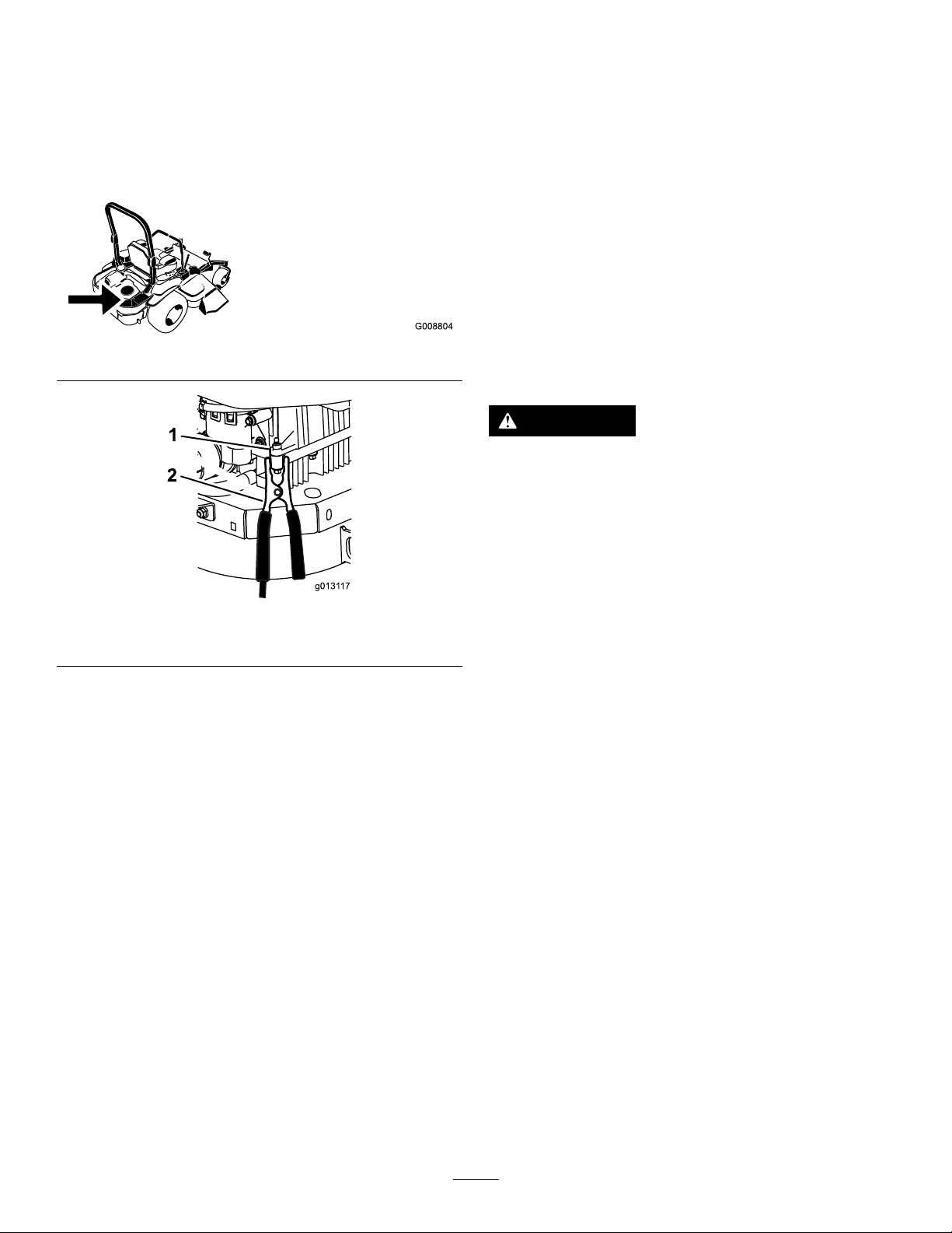
4.Connecttheotherendofthepositivecabletothe
G008804
g0131 17
1
2
positiveterminaloftheboosterbattery.
DriveSystem
5.Connecttheblacknegative(–)cabletotheother
terminal(negative)oftheboosterbattery.
6.Makethenalconnectionontheengineblockof
thestalledvehicle(nottothenegativebatterypost)
awayfromthebatteryandstandback(Figure64).
Figure63
Maintenance
CheckingtheSeatBelt
ServiceInterval:Beforeeachuseordaily
Visuallyinspectseatbeltforwear,cuts,andproperoperation
ofretractorandbuckle.Replacebeforeoperatingifdamaged.
CheckingtheKnobsonthe RolloverProtectionSystem (ROPS)
ServiceInterval:Beforeeachuseordaily
WARNING
Toavoidinjuryordeathfromrollover:keeptheroll
barinthefullyraisedlockedpositionandusethe
seatbelt.
Ensurethattherearpartoftheseatissecuredwith
theseatlatch.
Figure64
1.Engineblock
7.Startthevehicleandremovethecablesinthe
reverseorderofconnection(theengineblock(black)
connectionisthersttodisconnect).
2.Negative(–)cable
Checkthatboththemountinghardwareandtheknobsare
ingoodworkingcondition.Makesuretheknobsarefully
engagedwiththeROPSinthefullyraisedposition.The
upperhoopoftherollbarmayneedtobepushedforwardor
pulledrearwardtogetbothknobsfullyengaged.
44
Page 45
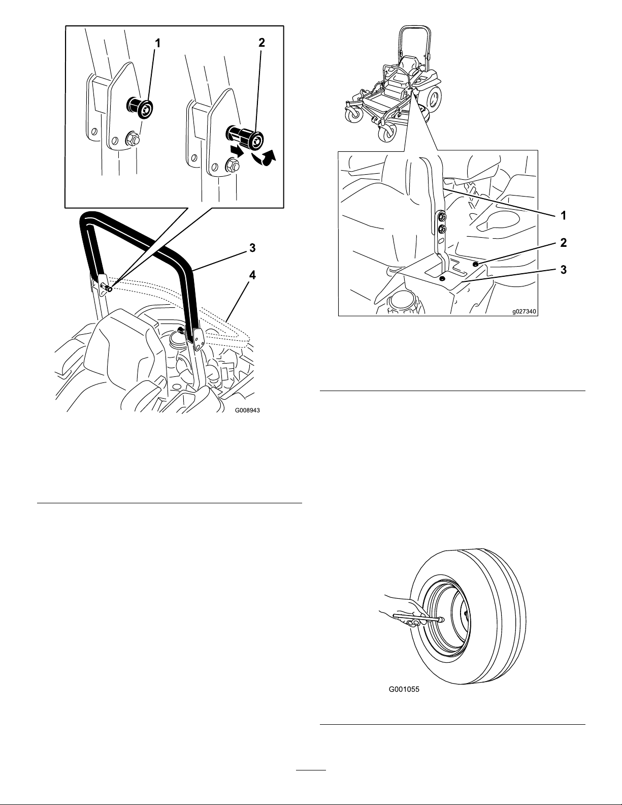
g027340
Figure66
Leftcontrollevershown
1.Controllever3.Stopplate
2.Bolt
Figure65
1.ROPSknob(locked
position)
2.PullROPSknoboutand
rotate90degreesto
changerollbarposition
3.Rollbarintheupright
position
4.Rollbarinthefolded
position
AdjustingtheTracking
1.Disengagetheblade-controlswitch(PTO).
2.Drivetoanopenatarea,movethemotion-control
leverstotheneutral-lockedposition.
3.Movethethrottlemidwaybetweenfastandslow.
4.Movebothmotion-controlleversallthewayforward
untiltheybothhitthestopsintheT-slot.
5.Checkwhichwaythemachinetracks.
6.Ifittrackstotheright,loosentheboltsandadjust
theleftstopplaterearwardontheleftT-slotuntilthe
machinetracksstraight(Figure66).
7.Ifittrackstotheleft,loosentheboltsandadjustthe
rightstopplaterearwardontherightT-slotuntilthe
machinetracksstraight(Figure66).
8.Tightenthestopplate(Figure66).
CheckingtheTirePressure
ServiceInterval:Every50hours/Monthly(whichever
comesrst)
Maintaintheairpressureinthereartiresat90kPa(13psi).
Uneventirepressurecancauseunevencut.Checkthetires
whentheyarecold,togetthemostaccuratepressurereading.
Note:Thefronttiresaresemi-pneumatictiresanddonot
requireairpressuremaintenance.
Figure67
45
Page 46
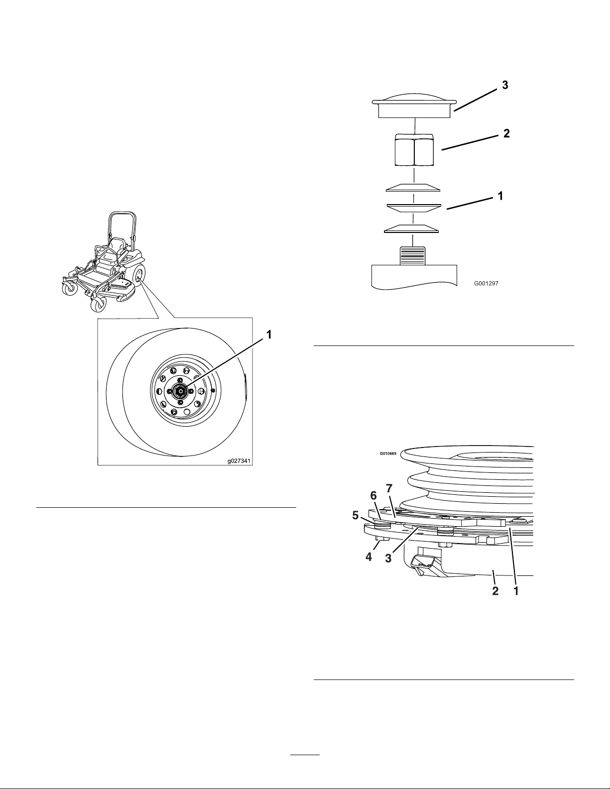
CheckingtheWheelLugNuts
g027341
Checkandtorquethewheellugnutsto122to129N-m(90
to95ft-lb).
CheckingtheWheelHub SlottedNut
ServiceInterval:Aftertherst100hours
Every500hours
Checkandensurethatthetorqueoftheslottednutis286to
352N-m(211to260ft-lb).
Note:Donotuseanti-seizeonwheelhub.
Important:Makesurethatthespringwashersare
installedcorrectlyasshowninFigure69.
5.Installthedustcap(Figure69).
Figure69
Figure68
1.Slottednut
AdjustingtheCasterPivot Bearing
ServiceInterval:Every500hours/Yearly(whichevercomes
rst)
1.Disengagetheblade-controlswitch(PTO),movethe
motion-controlleverstotheneutral-lockedposition
andsettheparkingbrake.
2.Stoptheengine,removethekey,andwaitforallmoving
partstostopbeforeleavingtheoperatingposition.
3.Removethedustcapfromthecasterandtightenthe
locknut(Figure69).
4.Tightenthelocknutuntilthespringwashersareatand
thenbackoffa1/4turntoproperlysetthepre-loadon
thebearings(Figure69).
1.Springwashers
2.Locknut
3.Dustcap
UsingtheClutchShim
Somelatermodelyearunitshavebeenbuiltwithclutchesthat
containabrakeshim.Whentheclutchbrakehasworntothe
pointwheretheclutchnolongerengagesconsistently,the
shimcanberemovedtoextendtheclutchlife.
Figure70
1.Armature5.Brakespacer
2.Fieldshell6.Re-gapshim
3.Rotor7.Brakepole
4.Brakemountingbolt
46
Page 47
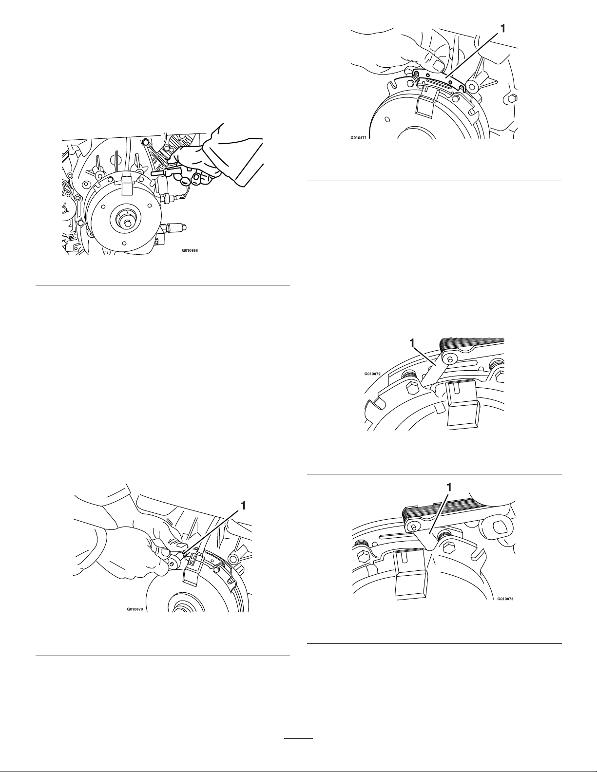
RemovingtheClutchShim
1.Stoptheengine,waitforallmovingpartstostop,and
removethekey.Engagetheparkingbrake.Allow
themachinetocoolcompletelybeforestartingthese
instructions.
2.Usinganaircompressor,blowoutanydebrisfrom
underthebrakepoleandaroundthebrakespacers.
Figure71
3.Checktheconditionofthewireharnessleads,
connectors,andterminals.Cleanorrepairasnecessary.
4.Verifythat12Vispresentattheclutchconnectorwhen
thePTOswitchisengaged.
5.Measurethegapbetweentherotorandthearmature.
Ifthegapisgreaterthan1mm(0.04inch),proceed
withthefollowingsteps:
A.Loosenbothbrakemountingboltsone-halfto
onefullturnasshownbelow .
Figure73
1.Shim
C.Usingapneumaticline,blowoutanydebris
fromunderthebrakepoleandaroundthebrake
spacers.
D.Re-torqueeachbolt(M6x1)to13N-m(10ft-lb)
+/-0.7N-m(0.5ft-lb).
E.Usinga0.010inchthickfeelergauge,verifythat
agapispresentbetweentherotorandarmature
faceonbothsidesofthebrakepoleasshown.
(Duetothewaytherotorandarmaturefaces
wear(peaksandvalleys)itissometimesdifcult
tomeasurethetruegap.)
Note:Donotremovethebrakepolefromthe
eldshell/armature.Thebrakepolehasworn
tomatchthearmatureandneedstocontinueto
matchaftertheshimisremovedtoensureproper
braketorque.
Figure72
1.Brakemountingbolt
B.Usingneedle-nosepliers,orbyhand,takeholdof
thetabandremovetheshim.
Note:Donotdiscardtheshimuntilproper
clutchfunctionhasbeenconrmed.
Figure74
1.Feelergauge
Figure75
1.Feelergauge
•Ifthegapislessthan0.010inch,thenreinstall
theshimandreferencetheTroubleshooting
section.
•Ifthegapissufcient,proceedtothesafety
checkinstepF.
47
Page 48
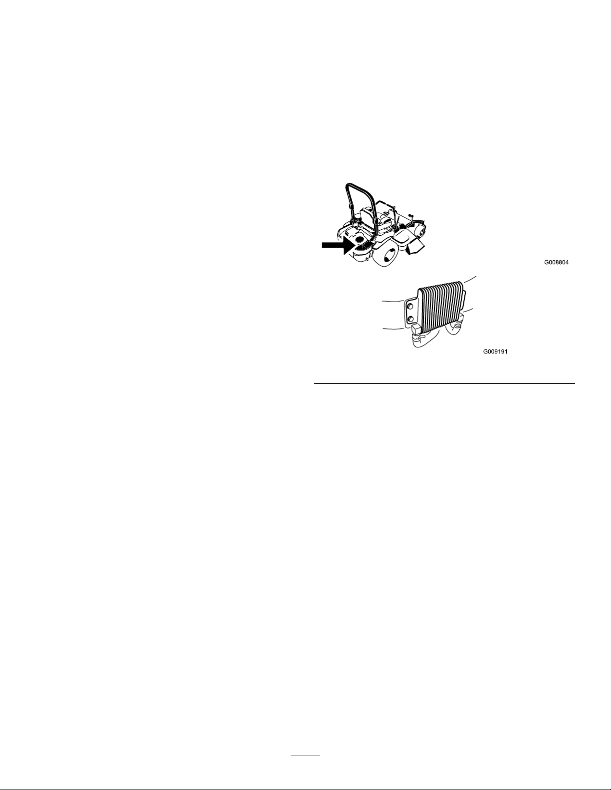
F.Performthefollowingsafetycheck:
G008804
i.Sitontheseatandstarttheengine.
ii.Makesurethatthebladesdonotengage
withthePTOswitchedoffandtheclutch
disengaged.
Iftheclutchdoesnotdisengage,installthe
shimandreferencetheTroubleshooting
section.
iii.EngageanddisengagethePTOswitch10
consecutivetimestoensurethattheclutch
isfunctioningproperly.Iftheclutch
doesnotengageproperly,referencethe
Troubleshootingsection.
CoolingSystem
Maintenance
CleaningtheEngineScreen andEngine-OilCooler
ServiceInterval:Beforeeachuseordaily
Removeanybuildupofgrass,dirt,orotherdebrisfromthe
oilcooler(Figure76).
Figure76
Beforeeachuseremoveanybuildupofgrass,dirt,or
otherdebrisfromtheenginescreen.Thiswillhelpensure
adequatecoolingandcorrectenginespeedandwillreduce
thepossibilityofoverheatingandmechanicaldamagetothe
engine(Figure77).
CleaningtheEngineCooling FinsandShrouds
ServiceInterval:Every100hours/Yearly(whichevercomes
rst)
1.DisengagethePTOandsettheparkingbrake.
2.Stoptheengine,removethekey,andwaitforallmoving
partstostopbeforeleavingtheoperatingposition.
3.Removetheairintakescreen,recoilstarter,andfan
housing(Figure77).
4.Cleanthedebrisandgrassfromtheengineparts.
5.Installairintakescreen,recoilstarter,andfanhousing
(Figure77).
48
Page 49
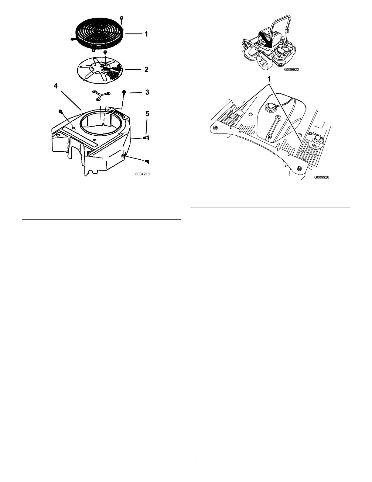
Figure77
1.Engineguard4.Fanhousing
2.Engineairintakescreen
3.Bolt
5.Screw
CheckandCleanthe Hydraulic-UnitShrouds
ServiceInterval:Beforeeachuseordaily
1.DisengagethePTOandsettheparkingbrake.
2.Stoptheengine,removethekey,andwaitforallmoving
partstostopbeforeleavingtheoperatingposition.
3.Raisetheseat.
4.Cleanthedebrisandgrassfromthehydraulicunit
shrouds(Figure78).
5.Lowertheseat.
Figure78
1.Hydraulicunitshrouds
49
Page 50
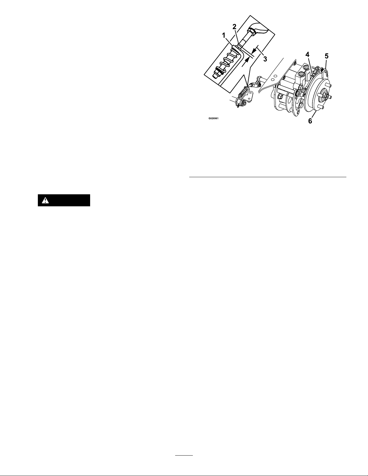
BrakeMaintenance
AdjustingtheParkingBrake
ServiceInterval:Aftertherst100hours
Every500hoursthereafter
Checktomakesurethebrakeisadjustedproperlybefore
adjusting.
Note:Thisproceduremustbefollowedaftertherst100
hoursorwhenabrakecomponenthasbeenremovedor
replaced.
1.Drivethemachineontoalevelsurface.
2.Disengagetheblade-controlswitch(PTO),movethe
motion-controlleverstotheneutral-lockedposition
andengagetheparkingbrake.
3.Stoptheengine,waitforallmovingpartstostop,and
removethekey.
4.Raisethebackofthemachineupandsupportthe
machinewithjackstands.
DANGER
Mechanicalorhydraulicjacksmayfailto
supportmachineandcauseaseriousinjury.
•Usejackstandwhensupportingmachine.
•Donotusehydraulicjacks.
5.Removethereartiresfromthemachine.
6.Removeanydebrisfromthebrakearea.
7.Rotatethedrivewheelreleasehandletothereleased
position.RefertoUsingtheDriveWheelRelease
Valves(page26).
Figure79
LeftSideShown
1.L-bracket4.Rearlinkageassembly
2.Linkagestop
3.Gap
9.Disengagetheparkingbrake,thelevershouldbein
thedownposition.
10.Turnthewheelhubbyhandinbothdirectionsrelative
tothecaliper;thewheelhubshouldmovefreely
betweenthecaliper.
11.Ifagapisneededorthewheelhubdoesnotmove
freely:
A.Disengagetheparkingbrake.
B.Disconnectandne-tunetherearlinkage
assembly:
5.Caliper
6.Wheelhub
•Shortenthelinktocreateagap.
•Lengthenthelinktoallowwheelhub
movement.
8.Checktoseeifthereisavisiblegapbetweenthe
L-bracketandthelinkagestop(Figure79).
C.Reconnecttherearlinkageassembly.
12.Engagetheparkingbrakeandcheckthegap.
13.Repeatsteps9through13untilavisiblegapisachieved
andthewheelhubrotatesfreely .
14.Repeatthisprocedureforthebrakeontheopposite
side.
15.Rotatethedrivewheelreleasehandletotheoperating
position.RefertoUsingtheDriveWheelRelease
Valves(page26).
16.Installthereartiresandtorquethelugnuts.Referto
CheckingtheWheelLugNuts(page46).
17.Removethejackstands.
50
Page 51
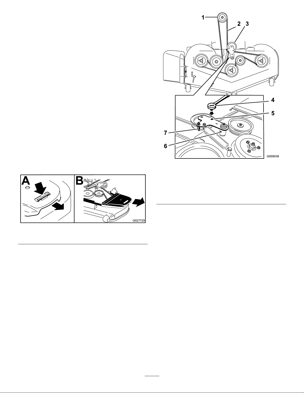
BeltMaintenance
InspectingtheBelts
ServiceInterval:Every50hours
Checkthebeltsforsquealingwhenthebeltisrotating,blades
slippingwhencuttinggrass,frayedbeltedges,burnmarks,
andcracks.Thesearesignsofawornmowerbelt;replacethe
mowerbeltifanyoftheseconditionsareevident.
ReplacingtheMowerBelt
Squealingwhenthebeltisrotating,bladesslippingwhen
cuttinggrass,frayedbeltedges,burnmarks,andcracksare
signsofawornmowerbelt.Replacethemowerbeltifanyof
theseconditionsareevident.
1.DisengagethePTO,movethemotion-controlleversto
theneutral-lockedposition,andsettheparkingbrake.
2.Stoptheengine,removethekey,andwaitforallmoving
partstostopbeforeleavingtheoperatingposition.
3.Lowerthemowertothe76mm(3inch)heightofcut.
4.Removethebeltcovers(Figure80).
Figure80
1.Pushtabdown2.Removebeltcover
5.Usearatchetinthesquareholeintheidlerarmto
removetensionontheidlerspring(Figure81).
6.Removethebeltfromthemowerdeckpulleys.
7.Removethebeltguideonthespring-loadedidlerarm
showninFigure81.
8.Removetheexistingbelt.
9.Installthenewbeltaroundthemowerpulleysandthe
clutchpulleyundertheengine(Figure81).
Figure81
1.Clutchpulley5.Squareholeintheidler
2.Mowerbelt
3.Spring-loadedidlerpulley
4.Ratchet
10.InstallthebeltguideontheidlerarmshowninFigure
81.
11.Usingtheratchetinthesquarehole,installtheidler
spring(Figure81).
Makesurethatthespringendsareseatedintheanchor
grooves.
12.Installthebeltcovers(Figure82).
armfortheratchet
6.Idlergreasetting
7.Beltguide
51
Page 52
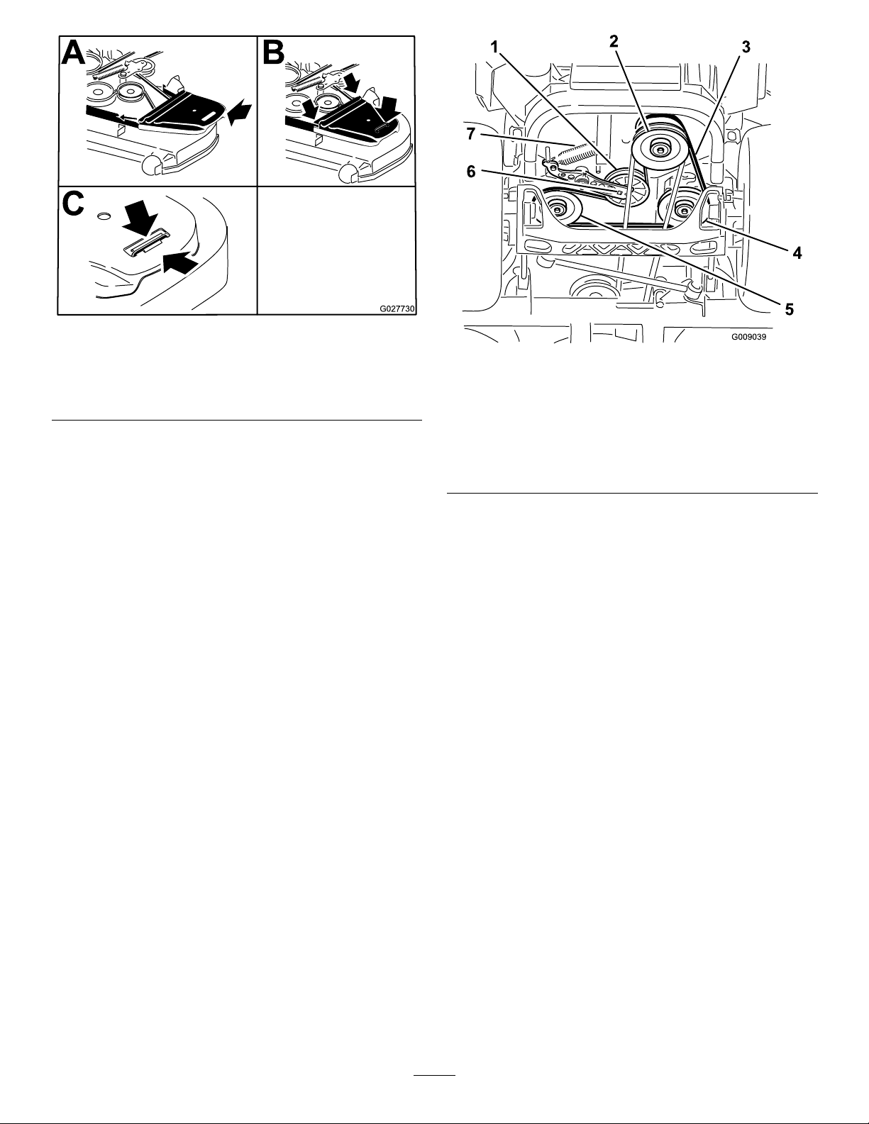
Figure82
1.Positionthebeltcover3.Ensurethatthetabis
underthemetalcatch
2.Slidebeltcoverunderthe
sidecatches
ReplacingtheHydraulicPump DriveBelt
1.DisengagethePTOandsettheparkingbrake.
2.Stoptheengine,removethekey,andwaitforallmoving
partstostopbeforeleavingtheoperatingposition.
3.Removethemowerbelt.RefertoReplacingtheMower
BeltinMaintenance.
4.Raisethemachineandsupportitwithjackstands
(Figure83).
Figure83
1.Idlerpulley
2.Clutchpulley6.Squareholeinidlerarm
3.Pumpdrivebelt7.Idlerspring
4.Right-handhydraulic
pumppulley
5.Left-handhydraulicpump
pulley
5.Usearatchetinthesquareholeintheidlerarmto
removetheidlerspring(Figure83).
6.Unhooktheidlerspringfromtheframe(Figure83).
7.Removethebeltfromthehydraulicunitdrivepulleys
andtheenginepulley
8.Installthenewbeltaroundenginepulleyandthetwo
drivepulleys.
9.Usingaratchetinthesquareholeintheidlerarm,
installtheidlerspringtotheframe(Figure83).
10.Installthemowerbelt.RefertoReplacingtheMower
Belt.
52
Page 53
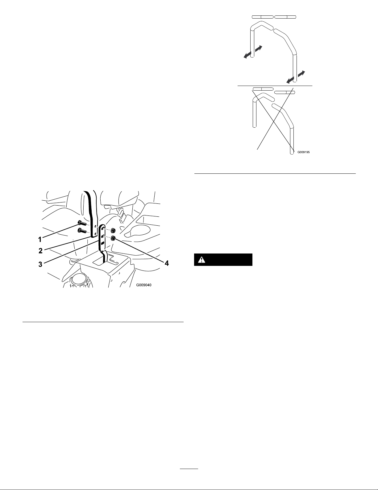
ControlsSystem
Maintenance
AdjustingtheControlHandle Position
Thereare2heightpositionsforthecontrollevers:highand
low .Removetheboltstoadjusttheheightfortheoperator.
1.DisengagethePTO,movethemotion-controlleversto
theneutral-lockedposition,andsettheparkingbrake.
2.Stoptheengine,removethekey,andwaitforallmoving
partstostopbeforeleavingtheoperatingposition.
3.Loosentheboltsandangenutsinstalledinthelevers
(Figure84).
4.Alignthefront-to-rearpositionoftheleversby
bringingtheleverstogethertotheneutralpositionand
slidingthemuntiltheyarealigned;thentightenthe
bolts(Figure85).
Figure84
1.Bolt
2.Handle4.Nut
3.Controllever
Figure85
AdjustingtheMotion-Control Linkage
Locatedoneithersideofthefueltank,belowtheseatare
thepumpcontrollinkages.Rotatingthepumplinkagewitha
1/2inchwrenchallowsnetuningadjustmentssothatthe
machinedoesnotmoveinneutral.Anyadjustmentsshould
bemadeforneutralpositioningonly .
WARNING
Theenginemustberunningandthedrivewheels
mustbeturningsothatthemotioncontrol
adjustmentcanbeperformed.Contactwithmoving
partsorhotsurfacesmaycausepersonalinjury.
Keepngers,hands,andclothingclearofrotating
componentsandhotsurfaces.
1.Priortostartingtheengine,pushthedeckliftpedal,
removetheheight-of-cutpin,andlowerthedeckto
theground.
2.Raisetherearofthemachineupandsupportitwith
jackstands(orequivalentsupport)justhighenoughto
allowthedrivewheelstoturnfreely .
3.Removetheelectricalconnectionfromtheseatsafety
switch,locatedunderthebottomcushionoftheseat.
Note:Theswitchisapartoftheseatassembly.
4.Temporarilyinstallajumperwireacrosstheterminals
intheconnectorofthemainwiringharness.
5.Starttheengine.
Note:Thebrakemustbeengaged,andthe
motion-controlleversout,tostarttheengine.The
operatordoesnothavetobeintheseatbecauseof
53
Page 54
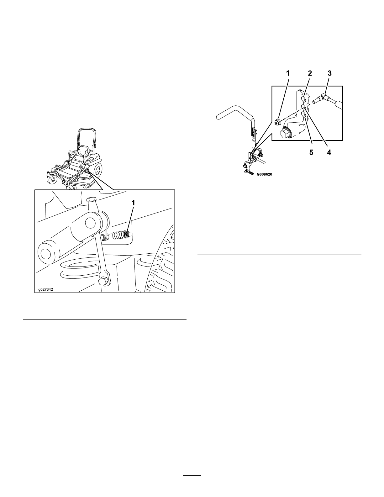
thejumperwirebeingused.Runtheengineatfull
g027342
throttleandreleasethebrake.
6.Runthemachineatleast5minuteswiththedrive
leversatfullforwardspeedtobringhydraulicoilup
tooperatingtemperature.
Note:Themotion-controlleverneedstobeinneutral
whilemakinganynecessaryadjustments.
7.Bringthemotion-controlleversintotheneutral
position.
8.Adjustthepumpcontrolrodlengthsbyrotatingthe
doublenutsontherodintheappropriatedirection
untilthewheelsslightlycreepinreverse(Figure86).
AdjustingtheMotion-Control Damper
Thetopdampermountingboltcanbeadjustedtoobtaina
moredesiredmotion-controlleverresistance.SeeFigure87
formountingoptions.
Figure87
Right-handmotioncontrolshown
Figure86
1.Doublenuts
9.Movethemotion-controlleverstothereverseposition
andwhileapplyingslightpressuretotheleverallow
thereverseindicatorspringstobringtheleversback
toneutral.
Note:Thewheelsmuststopturningorslightlycreep
inreverse.
10.Stoptheengine,removethejumperwirefromthewire
harness,andplugtheconnectorintotheseatswitch.
1.Torquethelocknutto23N-m(17ft-lb).Theboltmust
protrudepasttheendofthelocknutaftertorquing.
2.Mostresistance(rmestfeel)
3.Damper
4.Mediumresistance(mediumfeel)
5.Leastresistance(softestfeel)
AdjustingtheMotion-Control NeutralLockPivot
Theangednutcanbeadjustedtoobtainamoredesired
motion-controlleverresistancewhenmovingittotheneutral
lockposition.SeeFigure88foradjustmentoptions.
1.Loosenthejamnut.
2.Tightenorloosentheangednuttothedesiredfeel.
Formoreresistance,tightentheangednut.
Forlessresistance,loosentheangednut
3.Tightenthejamnut.
11.Removethejackstands.
12.Raisethedeckandinstalltheheight-of-cutpin.
13.Checkthatthemachinedoesnotcreepinneutralwith
theparkingbrakedisengaged.
54
Page 55

HydraulicSystem
Maintenance
ServicingtheHydraulic System
Figure88
1.Flangednut2.Jamnut
HydraulicOilType:T oro
orMobil
Important:Useoilspecied.Otheruidscouldcause
systemdamage.
EachHydraulicSystemOilCapacity:1.5L(1.59USqt)
persidewithlterchange
®
115W -50.
®
HYPR-OIL
™
500hydraulicoil
CheckingtheHydraulicOil
ServiceInterval:Every50hours—Checkthehydraulicoil
level.
1.Positionthemachineonalevelsurface.
2.DisengagethePTO,movethemotion-controlleversto
theneutral-lockedpositionandsettheparkingbrake.
3.Stoptheengine,removethekey,andwaitforallmoving
partstostopbeforeleavingtheoperatingposition.
4.Allowtheengineandthehydraulicsystemtocoolfor
10minutes.
Note:Theoillevelonthedipstickwillbeincorrectif
theoilischeckedwhenthemachineishot.
5.Movetheseatforward.
6.Cleantheareaaroundthedipsticksofthe
hydraulic-systemreservoirs(Figure89).
7.Removeonedipstickfromthehydraulicreservoir
(Figure89).
8.Wipethedipstickoffandthreadthedipstickintothe
reservoir.
9.Removethedipstickandlookattheend(Figure89).
Iftheoillevelisattheaddmark,slowlypouronly
enoughoilintothehydraulicreservoirtoraisethelevel
tothefullorHline.
Important:Donotoverllthehydraulicunits
withoilasdamagemayoccur.Donotrunthe
machinewiththeoilbelowtheaddmark.
10.Installthedipstick.
11.Repeatprocedurefortheoppositedipstick.
55
Page 56
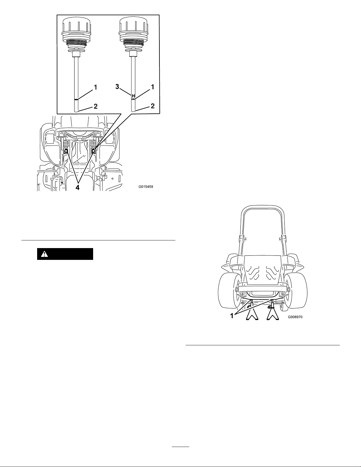
G015459
H
3
4
ReplacingtheHydraulicFiltersand
HydraulicOil
ServiceInterval:Aftertherst250hours—Changethe
hydraulicltersandhydraulicoilwhen
usinganytypeofoil.
Figure89
Eitherdipstickwillbeusedinthemachine
1.Full3.H—meanshighlevel
2.Add4.Dipsticklocationsunder
seat
Every250hours—Changethehydraulicltersand
hydraulicoilwhenusingMobil
®
1oil(moreoftenin
dirtyordustyconditions).
Every500hours—Changethehydraulicltersand
hydraulicoilwhenusingToro
®
HYPR-OIL
™
hydraulicoil(moreoftenindirtyordustyconditions).
Toreplacethehydraulicoil,theltersneedtoberemoved.
Replacebothatthesametime.Refertotheoilspecications
underServicingtheHydraulicSystem(page55)forthe
correctoil.
1.Disengagetheblade-controlswitch(PTO),movethe
motion-controlleverstotheneutral-lockedposition
andsettheparkingbrake.
2.Stoptheengine,removethekey,andwaitforallmoving
partstostopbeforeleavingtheoperatingposition.
3.Raisethemachineandsupportitwithjackstands
(Figure90).
500
WARNING
Hydraulicoilescapingunderpressurecan
penetrateskinandcauseinjury.
•Ifhydraulicoilisinjectedintotheskinit
mustbesurgicallyremovedwithinafew
hoursbyadoctorfamiliarwiththistype
ofinjury.Gangrenemayresultifthisis
notdone.
•Keepbodyandhandsawayfrompinhole
leaksornozzlesthatejecthighpressure
hydraulicoil.
•Usecardboardorpapertondhydraulic
leaks.
•Safelyrelieveallpressureinthehydraulic
systembeforeperforminganyworkonthe
hydraulicsystem.
•Makesureallhydraulicoilhosesandlines
areingoodconditionandallhydraulic
connectionsandttingsaretightbefore
applyingpressuretohydraulicsystem.
Figure90
1.Jackstands
4.Removeboththemowerbeltandthepumpdrivebelt.
Thiswillpreventoilgettingonthebelts.RefertoBelt
Maintenance(page51).
5.Placeadrainpanunderthelter,removetheoldlter
andwipethesurfaceclean(Figure91).
56
Page 57
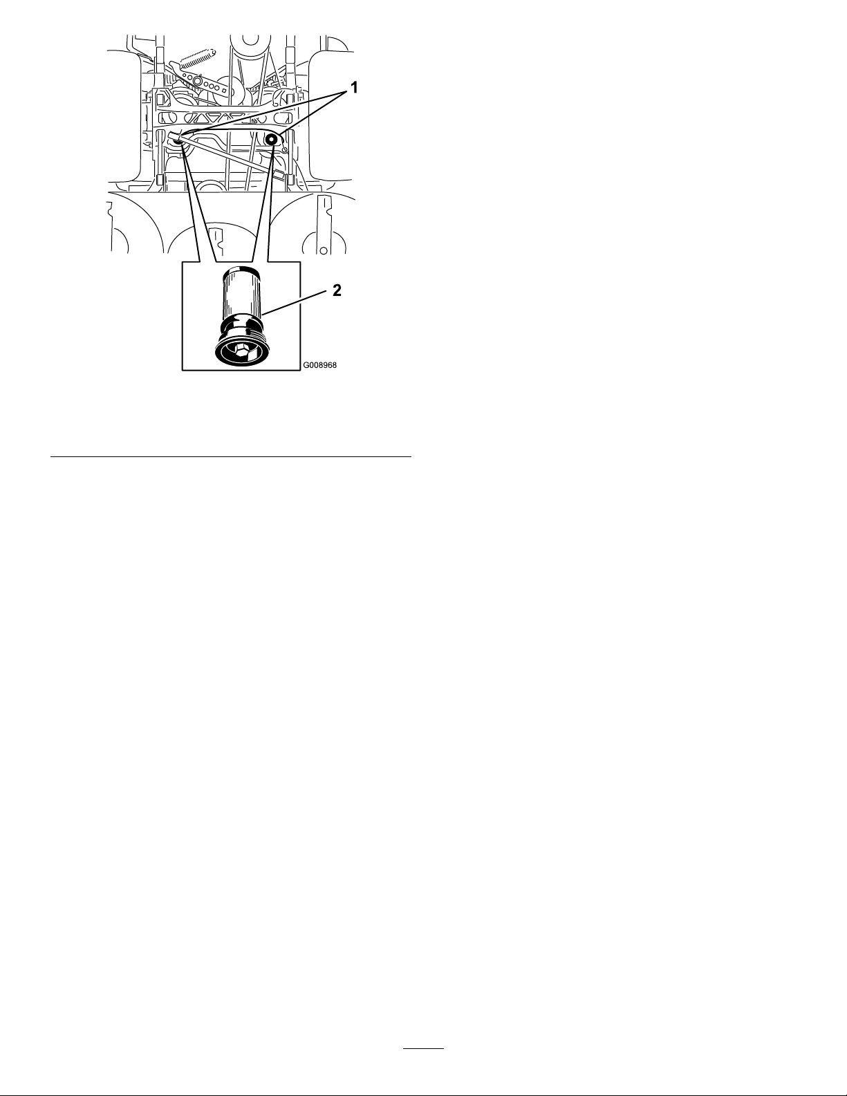
G008968
1
2
MowerDeck Maintenance
LevelingtheMowerDeck
SettingUptheMachine
Note:Ensurethatthemowerdeckisleveledbefore
matchingtheheightofcut(HOC).
1.Positionthemachineonaatsurface.
2.Disengagetheblade-controlswitch(PTO),movethe
motion-controlleverstotheneutral-lockedposition
andsettheparkingbrake.
3.Stoptheengine,removethekey,andwaitforallmoving
partstostopbeforeleavingtheoperatingposition.
Figure91
BottomViewofMachine
1.Filterlocations
6.Applyathincoatofhydraulicoiltotherubbergasket
onthereplacementlter(Figure91).
7.Installthereplacementhydrauliclter.
8.Installthepumpdrivebeltandthemowerbelt.
9.Removethejackstandsandlowerthemachine(Figure
90).
10.Addoiltothehydraulicreservoirandcheckforany
leaks.
11.Cleanupanyspilledoil.
12.Starttheengineandletitrunforabouttwominutesto
purgeairfromthesystem.Stoptheengineandcheck
forleaks.
13.Checktheoillevelwhiletheoiliscold.
14.Ifrequired,addoiltothehydraulicreservoir.Donot
overll.
2.Hydrauliclter
4.Checkthetirepressureofthedrivetires.Ifneeded,
adjustthepressureto90kPa(13psi)
5.Positionthemowertothe76mm(3inch)height-of-cut
position.
LevelingtheDeck
1.Positionthemoweronaatsurface.
2.Stopengine,waitforallmovingpartstostop,and
removekey.Engageparkingbrake.
3.Checkthetirepressureinthedrivetires.Proper
inationpressurefortiresis90kPa(13psi).Adjust
ifnecessary.
4.Positionthetransportlockinthelatchingposition.
5.Pushthedeckliftpedalallthewayforwardandthe
deckwilllatchatthe14cm(5-1/2inch)transport
position(Figure92).
57
Page 58
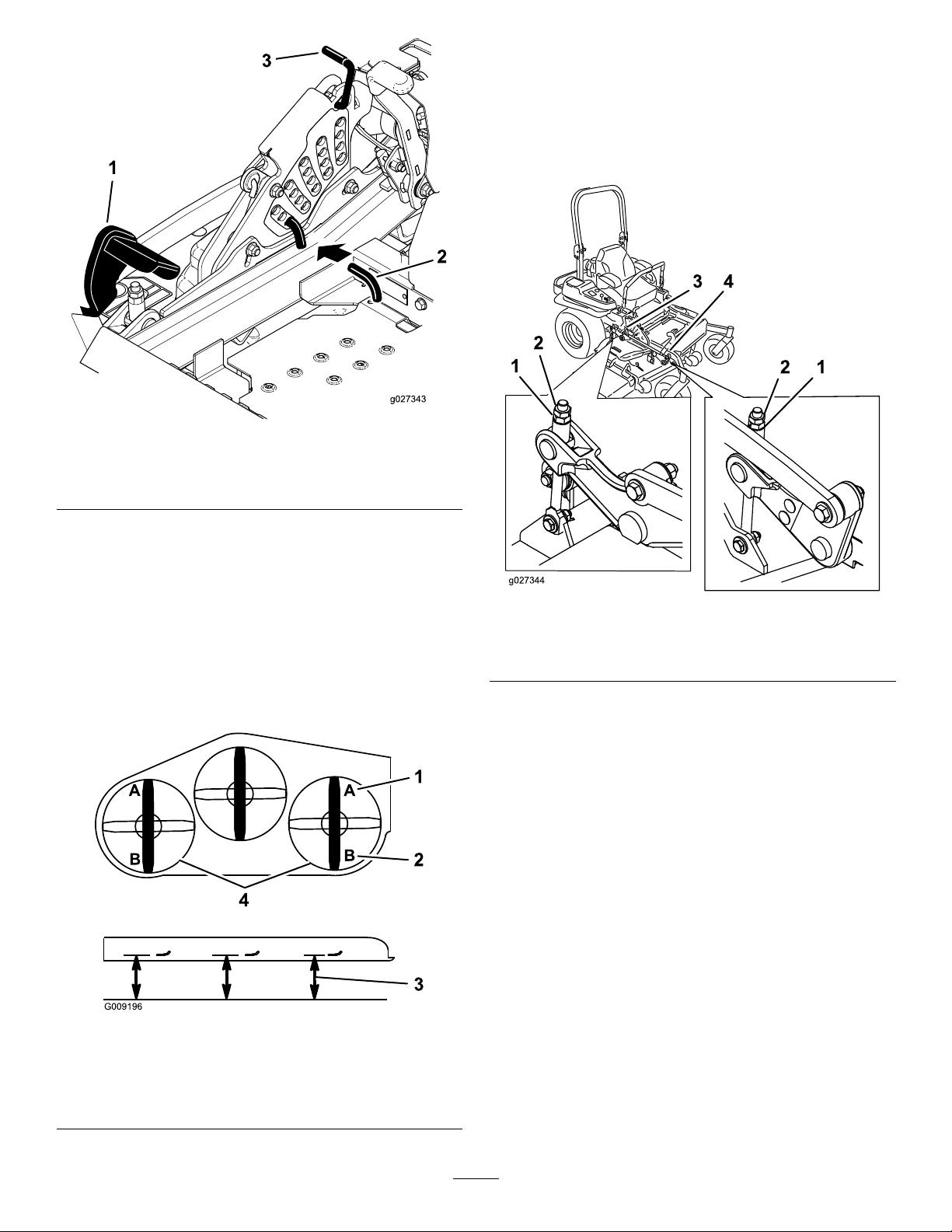
Figure92
g027344
1
2
2 1
3 4
10.Ifneeded,loosentheangedlocknutonthesideofthe
yokeandthejamnutontop.Fine-tunetheadjuster
screwbyturningittoget7.6mm(3inch)height
(Figure94).
Toincreasetheheight,turntheadjusterscrew
clockwise;todecreasetheheight,turnit
counterclockwise.
1.Deck-liftpedal
2.Height-of-cutpin
3.Transportlock
6.Inserttheheight-adjustmentpinintothe7.6cm(3
inch)cutting-heightposition.
7.Releasethetransportlockandallowthedecktolower
tothecuttingheight.
8.Raisethedischargechute.
9.Onbothsidesofthedeck,measurefromthelevel
surfacetothefronttipoftheblade(PostionA).The
measurementshouldread7.6mm(3inches);referto
Figure93.
Figure94
1.Flangedlocknut3.Jamnut
2.Adjusterscrew4.Yoke
11.Ifthefrontdecklinksdonothaveenoughadjustment
toachieveaccuratecutheight,thesinglepoint
adjustmentcanbeutilizedtogainmoreadjustment.
12.Toadjustthesinglepointsystem,loosenthetwobolts
atthebottomoftheheight-of-cutplate.Referto
Figure95.
1.7.6cm(3inches)atAis
correct
2.8.3cm(3-1/4inches)atB
iscorrect
Figure93
3.Measureherefromthe
bladetiptohardsurface
4.MeasureatAandBon
bothsides
58
Page 59
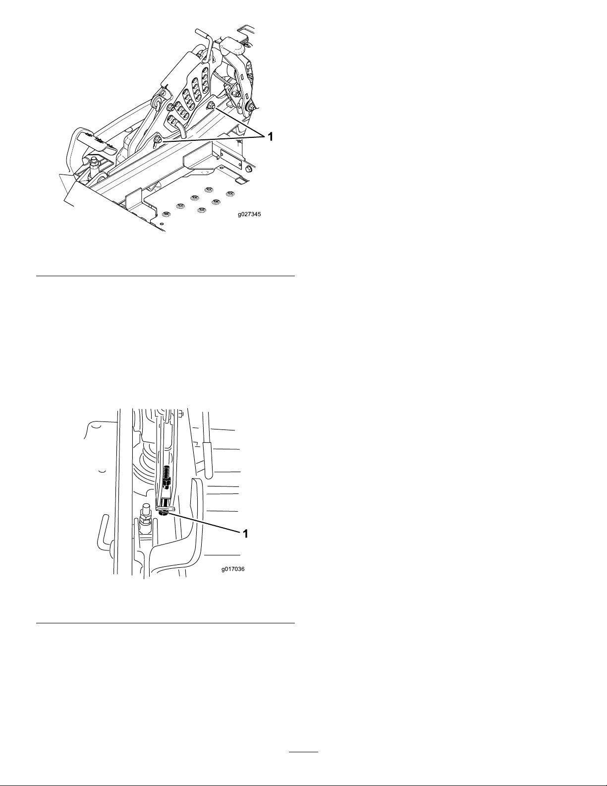
Figure95
g017036
1.Boltsatthebottomoftheheight-of-cutplate
13.Ifthedeckistoolow,tightenthesinglepoint
adjustmentboltbyrotatingitclockwise.Ifthedeckis
toohigh,loosenthesinglepointadjustmentboltby
rotatingitcounterclockwise(Figure96).
measurementshouldread8.3cm(3-1/4inches);refer
toFigure93.
16.Fine-tunetheadjusterscrewbyturningittoget8.3
mm(3-1/4inches)height(Figure94).
Toincreasetheheight,turntheadjustmentnut
clockwise;todecreasetheheight,turnthenut
counterclockwise.
17.Measureuntilall4sidesarethecorrectheight.Tighten
allthejamnutsonthedeck-liftarmassemblies.
18.Lowerthedischargechute.
Note:Loosenortightenthesinglepointadjustment
boltenoughtomovetheheight-of-cutplatemounting
boltsatleast1/3thelengthoftheavailabletravel
intheirslots.Thiswillregainsomeup-and-down
adjustmentoneachofthe4decklinks.
Figure96
1.Singlepointadjustmentbolt
14.Tightenthe2boltsatthebottomoftheheight-of-cut
plate(Figure95).Torquethemto37to45N-m(27
to33ft-lb).
Note:Inmostconditions,thebackbladetipshould
beadjusted6.4mm(1/4inch)higherthanthefront.
15.Onbothsidesofthedeck,measurefromthelevel
surfacetothebacktipoftheblade(PostionB).The
59
Page 60
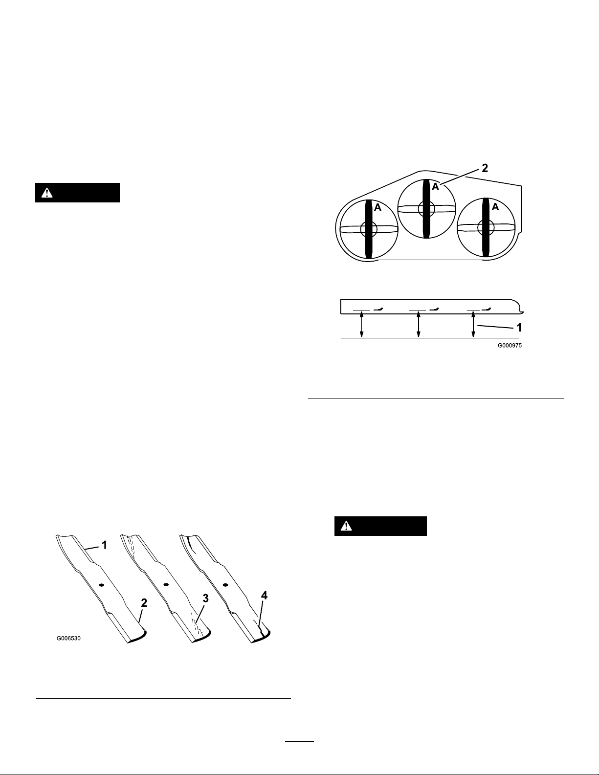
ServicingtheCuttingBlades
Maintainsharpbladesthroughoutthecuttingseason,because
sharpbladescutcleanlywithouttearingorshreddingthegrass
blades.Tearingandshreddingturnsgrassbrownattheedges,
whichslowsgrowthandincreasesthechanceofdisease.
Checkthecutterbladesdailyforsharpness,andforany
wearordamage.Filedownanynicksandsharpenthe
bladesasnecessary.Ifabladeisdamagedorworn,replace
itimmediatelywithagenuineT ororeplacementblade.For
convenientsharpeningandreplacement,youmaywantto
keepextrabladesonhand.
DANGER
Awornordamagedbladecanbreak,andapiece
ofthebladecouldbethrownintotheoperator's
orbystander'sarea,resultinginseriouspersonal
injuryordeath.
•Inspectthebladeperiodicallyforwearor
damage.
•Replaceawornordamagedblade.
CheckingforBentBlades
1.Disengagetheblade-controlswitch(PTO),movethe
motion-controlleverstotheneutral-lockedposition
andsettheparkingbrake.
2.Stoptheengine,removethekey,andwaitforallmoving
partstostopbeforeleavingtheoperatingposition.
3.Rotatethebladesuntiltheendsfaceforwardand
backward(Figure98).Measurefromalevelsurfaceto
thecuttingedge,positionA,oftheblades(Figure98).
Notethisdimension.
BeforeInspectingorServicingthe
Blades
Parkthemachineonalevelsurface,disengagethe
blade-controlswitch(PTO),andsettheparkingbrake.Turn
theignitionkeytoOff.Removethekey .
InspectingtheBlades
ServiceInterval:Beforeeachuseordaily
1.Inspectthecuttingedges(Figure97).Iftheedges
arenotsharporhavenicks,removeandsharpenthe
blades.RefertoSharpeningtheBlades.
2.Inspecttheblades,especiallythecurvedarea(Figure
97).Ifyounoticeanydamage,wear,oraslotforming
inthisarea(Figure97),immediatelyinstallanewblade.
Figure98
1.Measureherefromblade
tohardsurface
4.Rotatetheoppositeendsofthebladesforward.
5.Measurefromalevelsurfacetothecuttingedgeof
thebladesatthesamepositionasinstep3above.
Thedifferencebetweenthedimensionsobtainedin
steps3and4mustnotexceed1/8inch(3mm).Ifthis
dimensionexceeds1/8inch(3mm),thebladeisbent
andmustbereplaced;refertoRemovingtheBlades
andInstallingtheBlades.
2.PositionA
WARNING
Abladethatisbentordamagedcouldbreak
apartandcouldseriouslyinjureorkillyouor
bystanders.
•Alwaysreplacebentordamagedblade
withanewblade.
Figure97
1.Cuttingedge3.Wear/slotforming
2.Curvedarea4.Crack
•Neverleorcreatesharpnotchesinthe
edgesorsurfacesofblade.
RemovingtheBlades
Bladesmustbereplacedifasolidobjectishit,ifthebladeis
outofbalanceorisbent.Toensureoptimumperformance
andcontinuedsafetyconformanceofthemachine,use
genuineT ororeplacementblades.Replacementbladesmade
60
Page 61
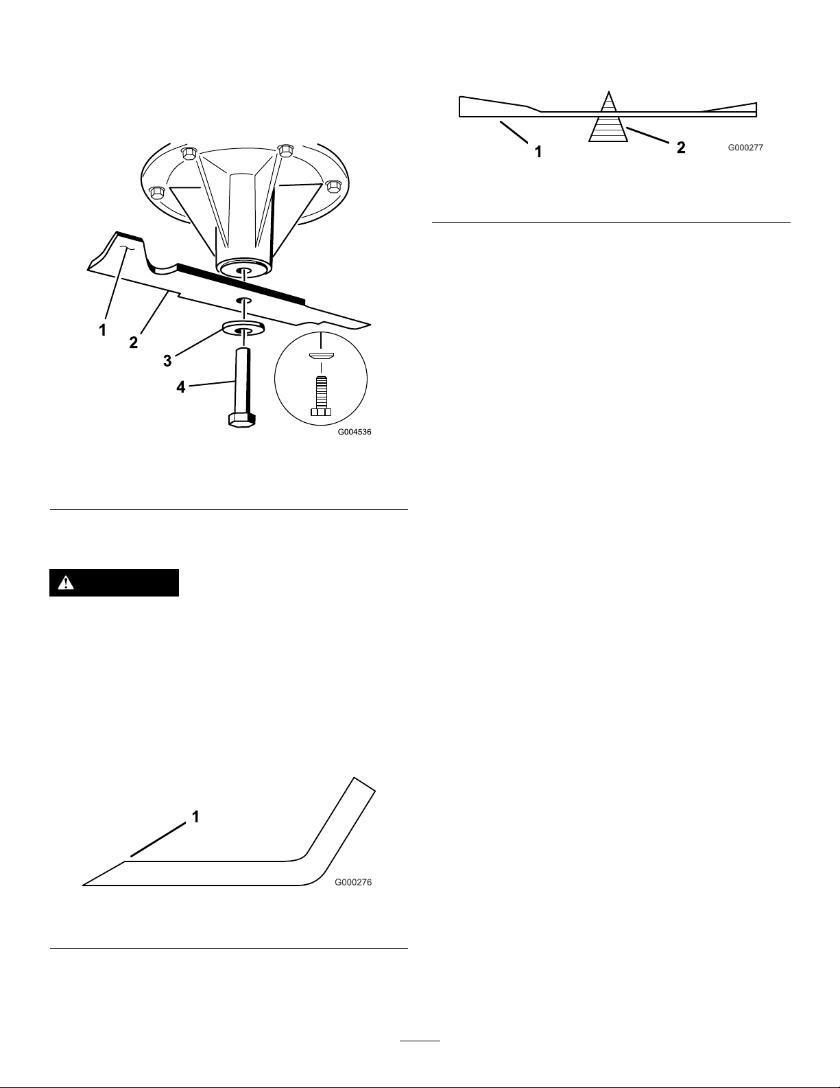
byothermanufacturersmayresultinnon-conformancewith
safetystandards.
1.Holdthebladeendusingaragorthickly-paddedglove.
2.Removethebladebolt,curvedwasher,andbladefrom
thespindleshaft(Figure99).
bladeisnotbalanced,lesomemetalofftheendof
thesailareaonly(Figure102).Repeatthisprocedure
untilthebladeisbalanced.
Figure101
1.Blade2.Balancer
Figure99
1.Sailareaofblade3.Curvedwasher
2.Blade4.Bladebolt
SharpeningtheBlades
WARNING
Whensharpeningblades,piecesofabladecouldbe
thrownandcauseseriousinjury.
Wearpropereyeprotectionwhensharpening
blades.
1.Usealetosharpenthecuttingedgeatbothendsof
theblade(Figure100).Maintaintheoriginalangle.The
bladeretainsitsbalanceifthesameamountofmaterial
isremovedfrombothcuttingedges.
Figure100
1.Sharpenatoriginalangle
2.Checkthebalanceofthebladebyputtingitonablade
balancer(Figure101).Ifthebladestaysinahorizontal
position,thebladeisbalancedandcanbeused.Ifthe
61
Page 62
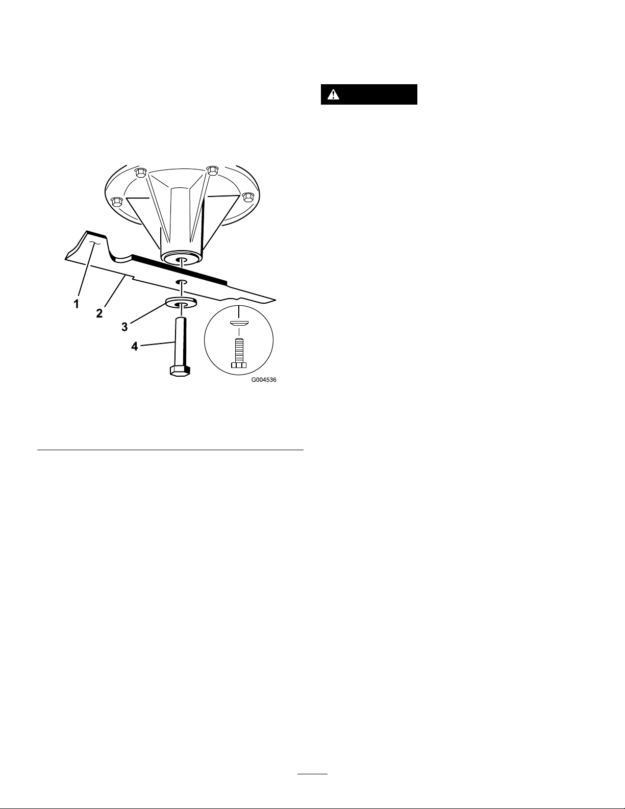
InstallingtheBlades
1.Installthebladeontothespindleshaft(Figure102).
Important:Thecurvedpartoftheblademustbe
pointingupwardtowardtheinsideofthemowerto
ensurepropercutting.
2.Installthespringdiskandthebladebolt.Thespring
diskconemustbeinstalledtowardthebolthead
(Figure102).Torquethebladeboltto115to150N-m
(85to110ft-lb).
RemovingtheMowerDeck
Beforeservicingorremovingthemowerdeck,the
spring-loadeddeckarmsmustbelockedout.
WARNING
Deckliftarmassemblieshavestoredenergy.
Removingthedeckwithoutreleasingthestored
energycancauseseriousinjuryordeath.
Donotattempttodisassemblethedeckfromthe
frontframewithoutlockingoutthestoredenergy.
1.Stoptheengine,waitforallmovingpartstostop,and
removethekey.Engagetheparkingbrake.
2.Removetheheight-adjustmentpinandlowerthedeck
totheground.
3.Placetheheight-adjustmentpininthe7.6cm(3inch)
cutting-heightlocation.
Note:Thislocksthedeckliftarmsinthelowest
positionwhenthedeckisremovedandthestored
energyinthedeckspringisreleased.
1.Sailareaofblade
2.Blade
3.Curvedwasher
Figure102
4.Bladebolt
5.Conetowardsbolthead
4.Removethebeltcovers.
5.Liftuptheoorpanandinsertaratchetintothesquare
holeinthedeckidler(Figure103).
6.Rotatethedeckidlerclockwiseandremovethemower
belt(Figure103).
62
Page 63
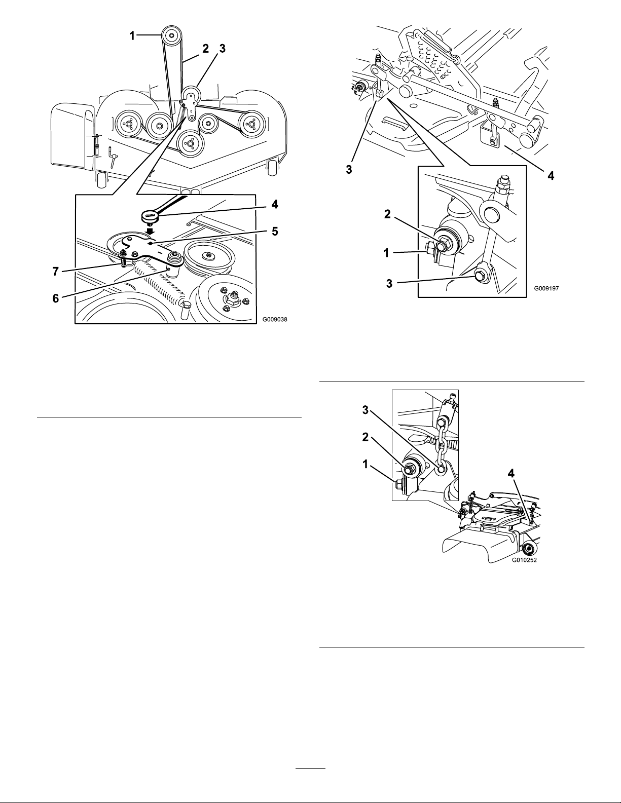
Figure104
Figure103
1.Clutchpulley5.Squareholeintheidler
2.Mowerbelt
3.Spring-loadedidlerpulley
4.Ratchet
armfortheratchet
6.Idlergreasetting
7.Beltguide
7.Removeandretainthehardwareonbothsidesofthe
deckasshowninFigure104orFigure105.
1.Rightstabilizer
2.Deckstrut(rightsideshown)
3.Removethereardeckliftattachmentshoulderboltandnut.
4.Removethefrontdeckliftattachmentshoulderboltandnut.
Figure105
1.Rightstabilizer
2.Deckstrut(rightsideshown)
3.Removethereardeckliftattachmentshoulderboltandnut.
4.Removethefrontdeckliftattachmentshoulderboltandnut.
8.Raisethedeckstrutsandsecurethemintheup
position.Slidethedeckouttotherightsideofthe
machine.
63
Page 64
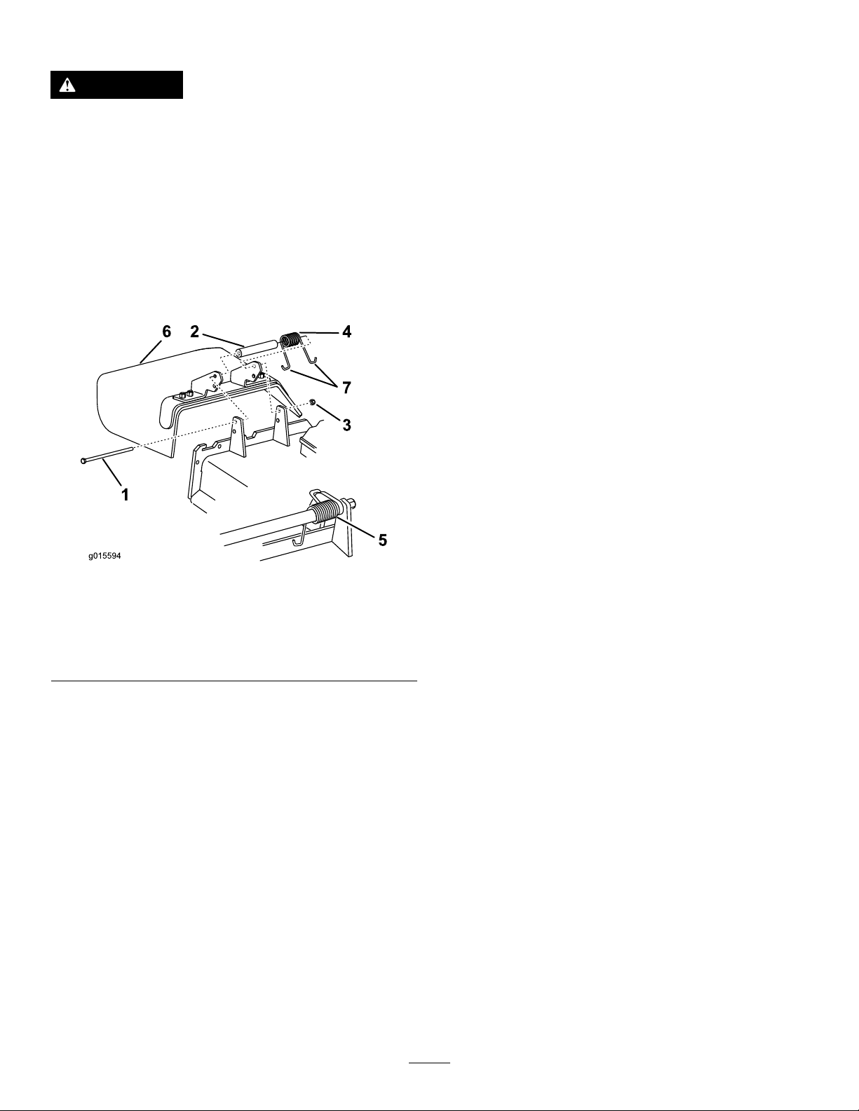
ReplacingtheGrassDeector
g015594
1
6 2
4
7
3
5
Cleaning
WARNING
Operatingthemachinewiththeenginerunningat
aspeedgreaterthanthefactorysettingcancause
themachinetothrowapartofthebladeorengine
towardtheoperatororabystanderandresultin
seriouspersonalinjuryordeath.
Neveroperatethemachineunlessyouinstallacover
plate,amulchplate,agrassdeector,orabagger.
1.Removethelocknut,bolt,spring,andspacerholding
thedeectortothepivotbrackets(Figure106).
Removethedamagedorworngrassdeector.
CleaningundertheMower
ServiceInterval:Beforeeachuseordaily
1.Disengagetheblade-controlswitch(PTO),movethe
motion-controlleverstotheneutral-lockedposition
andsettheparkingbrake.
2.Stoptheengine,removethekey,andwaitforallmoving
partstostopbeforeleavingtheoperatingposition.
3.Raisethemowertothetransportposition.
DisposingofWaste
Engineoil,batteries,hydraulicoil,andenginecoolantare
pollutantstotheenvironment.Disposeoftheseaccordingto
yourstateandlocalregulations.
Figure106
1.Bolt
2.Spacer6.Grassdeector
3.Locknut
4.Spring
2.Placethespacerandthespringontothegrassdeector.
PlaceoneJendofthespringbehindthedeckedge.
Note:MakesureoneJ-endofthespringisinstalled
behindthedeckedgebeforeinstallingtheboltas
showninFigure106.
3.Installtheboltandthenut.PlaceoneJ-hookendof
thespringaroundthegrassdeector(Figure106).
Important:Thegrassdeectormustbeable
torotate.Liftthedeectoruptothefullopen
positionandensurethatitrotatesintothefull
downposition.
5.Springinstalled
7.J-hookendofspring
64
Page 65

Storage
CleaningandStorage
1.Disengagethepowertakeoff(blade-controlswitch
(PTO),settheparkingbrake,andturntheignitionkey
toOff.Removethekey.
2.Removegrassclippings,dirt,andgrimefromthe
externalpartsoftheentiremachine,especiallythe
engineandhydraulicsystem.Cleandirtandchafffrom
theoutsideoftheenginecylinderheadnsandblower
housing.
Important:Y oucanwashthemachinewithmild
detergentandwater.Donotpressurewashthe
machine.Avoidexcessiveuseofwater,especially
nearthecontrolpanel,engine,hydraulicpumps,
andmotors.
3.Checkthebrake;refertoBrakeMaintenance(page50).
4.Servicetheaircleaner;refertoServicingtheAir
Cleaner(page34).
5.Greasethemachine;refertoLubrication(page31)
D.Restarttheengineandrunituntilitstops.
E.Disposeoffuelproperly .Recycleasperlocal
codes.
Important:Donotstore
stabilizer/conditionedfuelover90days.
13.Checkandtightenallbolts,nuts,andscrews.Repairor
replaceanypartthatisdamaged.
14.Paintallscratchedorbaremetalsurfaces.Paintis
availablefromyourAuthorizedServiceDealer.
15.Storethemachineinaclean,drygarageorstoragearea.
Removethekeyfromtheignitionswitchandkeepit
outofreachofchildrenorotherunauthorizedusers.
Coverthemachinetoprotectitandkeepitclean.
6.Changethecrankcaseoil;refertoChangingtheEngine
Oil(page36).
7.Checkthetirepressure;refertoCheckingtheTire
Pressure(page45).
8.Changethehydrauliclters;refertoServicingthe
HydraulicSystem(page55).
9.Chargethebattery;refertoServicingtheBattery(page
41).
10.Scrapeanyheavybuildupofgrassanddirtfromthe
undersideofthemower,thenwashthemowerwith
agardenhose.
Note:Runthemachinewiththeblade-controlswitch
(PTO)engagedandtheengineathighidlefor2to
5minutesafterwashing.
11.Checktheconditionoftheblades;refertoServicing
theCuttingBlades(page60).
12.Forstorageover30days,preparethemachineas
follows:
A.Addapetroleum-basedstabilizer/conditionerto
fuelinthetank.Followthemixinginstructions
fromthestabilizermanufacturer.Donotusean
alcohol-basedstabilizer(ethanolormethanol).
Note:Afuelstabilizer/conditionerismost
effectivewhenmixedwithfreshfuelandusedat
alltimes.
B.Runtheenginetodistributeconditionedfuel
throughthefuelsystem(5minutes).
C.Stoptheengine,allowittocool,anddrainthefuel
tank;refertoServicingtheFuelTank(page41).
65
Page 66

Troubleshooting
Problem
ThemalfunctionIndicatorLight(MIL)
comeson.
Thestarterdoesnotcrank.
PossibleCauseCorrectiveAction
1.Theengineistoohot.
2.Thereisoldgasinthegastank.2.Usenewgas.
3.Thefuelshut-offvalveisnotopen
completely.
4.Theaircleanerisdirty.4.Makesurethattheaircleanerand
5.Thebatteryisnotcharged.
6.Incorrectfuelltersarebeingusedor
thefuelltersaredirty.
7.Theconnectionstothesensors
electroniccontrolunit(ECU)andfuel
injectorsarenotsecuredproperly .
8.Thereislowvoltagefromthebattery.
9.Afuseisblown.9.Checkandreplaceanyblownfuses.
1.Theblade-controlswitch(PTO)is
engaged.
2.Theparkingbrakeisnoton.
3.Themotion-controlleversarenotin
theneutral-lockposition.
4.Theoperatorisnotseated.
5.Thebatteryisdead.
6.Theelectricalconnectionsare
corrodedorloose.
7.Thefuseisblown.7.Replacethefuse.
8.Therelayorswitchiswornor
damaged.
1.Turntheengineoffandletitcool.
3.Openthefuelshut-offvalve.
precleanerareclean.Replaceif
necessary.
5.Chargeorreplacethebattery.
6.ContactanAuthorizedServiceDealer.
7.ContactanAuthorizedServiceDealer.
8.Ensureagood12voltbatteryisbeing
usedandisfullycharged.
1.Movetheblade-controlswitch(PTO)
tothedisengagedposition.
2.Settheparkingbrake.
3.Ensurethatthemotion-controllevers
areintheneutral-lockposition.
4.Sitontheseat.
5.Chargethebattery.
6.Checktheelectricalconnectionsfor
goodcontact.
8.ContactanAuthorizedServiceDealer.
Theenginedoesnotstart,startshard,or
failstokeeprunning.
1.Thefueltankisempty.1.Fillthefueltank.
2.Thefuel-shutoffvalveisclosed.2.Openthefuel-shutoffvalve.
3.Theoillevelinthecrankcaseislow.3.Addoiltothecrankcase.
4.Thethrottleisnotinthecorrect
position.
5.Thereisdirtinthefuellter.5.Replacethefuellter.
6.Thereisdirt,water,orstalefuelisin
thefuelsystem.
7.Theaircleanerisdirty.
8.Theseatswitchisnotfunctioning
properly.
9.Theelectricalconnectionsare
corroded,loose,ordamaged.
10.Therelayorswitchiswornor
damaged.
11.Thesparkplugisfouledorimproperly
gapped.
12.Thespark-plugwireisnotconnected.
4.Besurethatthethrottlecontrolis
midwaybetweentheslowandfast
positions.
6.ContactanAuthorizedServiceDealer.
7.Cleanorreplacetheair-cleaner
element.
8.Checktheseat-switchindicator.
Replacetheseatifnecessary .
9.Checktheelectricalconnections
forgoodcontact.Cleanthe
connectorterminalsthoroughlywith
electrical-contactcleaner,apply
dielectricgrease,andmakethe
appropriateconnections.
10.ContactanAuthorizedServiceDealer.
11.Adjustorreplacethesparkplug.
12.Checkthespark-plugwireconnection.
66
Page 67

Problem
PossibleCauseCorrectiveAction
Theenginelosespower.
Theengineoverheats.
Themowerpullstotheleftorright(with
leversfullyforward)
Themachinedoesnotdrive.
1.Theengineloadisexcessive.1.Reducethegroundspeed.
2.Theaircleanerisdirty.
3.Theoillevelinthecrankcaseislow.3.Addoiltothecrankcase.
4.Thecoolingnsandtheairpassages
abovetheengineareplugged.
5.Theventholeinthefuelcapisplugged.5.Cleanorreplacethefuelcap.
6.Thereisdirtinthefuellter.6.Replacethefuellter.
7.Thereisdirt,water,orstalefuelisin
thefuelsystem.
1.Theengineloadisexcessive.1.Reducethegroundspeed.
2.Theoillevelinthecrankcaseislow.2.Addoiltothecrankcase.
3.Thecoolingnsandtheairpassages
abovetheengineareplugged.
1.Thetrackingneedsadjustment1.Adjustthetracking.
2.Thetirepressureinthedrivetiresis
notcorrect.
1.Thebypassvalvesarenotclosedtight.1.Tightenthebypassvalves.
2.Thepumpbeltisworn,loose,or
broken.
3.Thepumpbeltisoffapulley.3.Changethebelt.
4.Theidlerspringisbrokenormissing.4.Replacethespring.
5.Thehydraulicoillevelislowortoohot.5.Addhydraulicoiltothereservoirsor
2.Cleantheair-cleanerelement.
4.Removetheobstructionfromthe
coolingnsandtheairpassages.
7.ContactanAuthorizedServiceDealer.
3.Removetheobstructionfromthe
coolingnsandtheairpassages.
2.Adjustthetirepressureinthedrive
tires.
2.Changethebelt.
letitcooldown.
Themachinevibratesabnormally .
Themachineproducesanunevencutting
height.
Thebladesdonotrotate.
1.Thecuttingblade(s)is/arebentor
unbalanced.
2.Theblademountingboltisloose.2.Tightentheblademountingbolt.
3.Theenginemountingboltsareloose.3.Tightentheenginemountingbolts.
4.Theenginepulley,idlerpulley ,orblade
pulleyisloose.
5.Theenginepulleyisdamaged.
6.Thebladespindleisbent.
7.Themotormountislooseorworn.
1.Theblade(s)is/arenotsharp.1.Sharpentheblade(s).
2.Thecuttingblade(s)is/arebent.2.Installnewcuttingblade(s).
3.Themowerdeckisnotlevel.
4.Theundersideofmowerisdirty.4.Cleantheundersideofthemower.
5.Thetirepressureisnotcorrect.5.Adjustthetirepressure.
6.Thebladespindleisbent.
1.Themowerdeckbeltisworn,loose,
orbroken.
2.Themowerdeckbeltisoffpulley.
3.Thepumpdrivebeltisworn,loose,or
broken.
4.Theidlerspringisbrokenormissing.4.Replacethespring.
1.Installnewcuttingblade(s).
4.Tightentheappropriatepulley .
5.ContactanAuthorizedServiceDealer.
6.ContactanAuthorizedServiceDealer.
7.ContactanAuthorizedServiceDealer.
3.Levelthemowerdeckfromside-to-side
andfront-to-rear.
6.ContactanAuthorizedServiceDealer.
1.Installanewdeckbelt.
2.Installthemowerdeckpulleyand
checktheidlerpulley,idlerarm,and
springforcorrectpositionandfunction.
3.Checkthebelttensionorinstallanew
belt.
67
Page 68

Problem
PossibleCauseCorrectiveAction
Theclutchdoesnotengage.
1.Thefuseisblown.1.Replacethefuse.Checkthecoil
2.Thereislowvoltagesupplyatthe
clutch.
3.Thecoilisdamaged.3.Replacetheclutch.
4.Thereisinadequatecurrentsupply.4.Repairorreplacetheclutchlead
5.Therotor/armatureairgapistoolarge.
resistance,batterycharge,charging
system,andwiringconnections,and
replacecomponentsifnecessary.
2.Checkthecoilresistance,battery
charge,chargingsystem,andwiring
connectionsandreplacepartsif
necessary.
wireorelectricalsystem.Cleanthe
connectorcontacts.
5.Removetheshimorreplacetheclutch.
68
Page 69
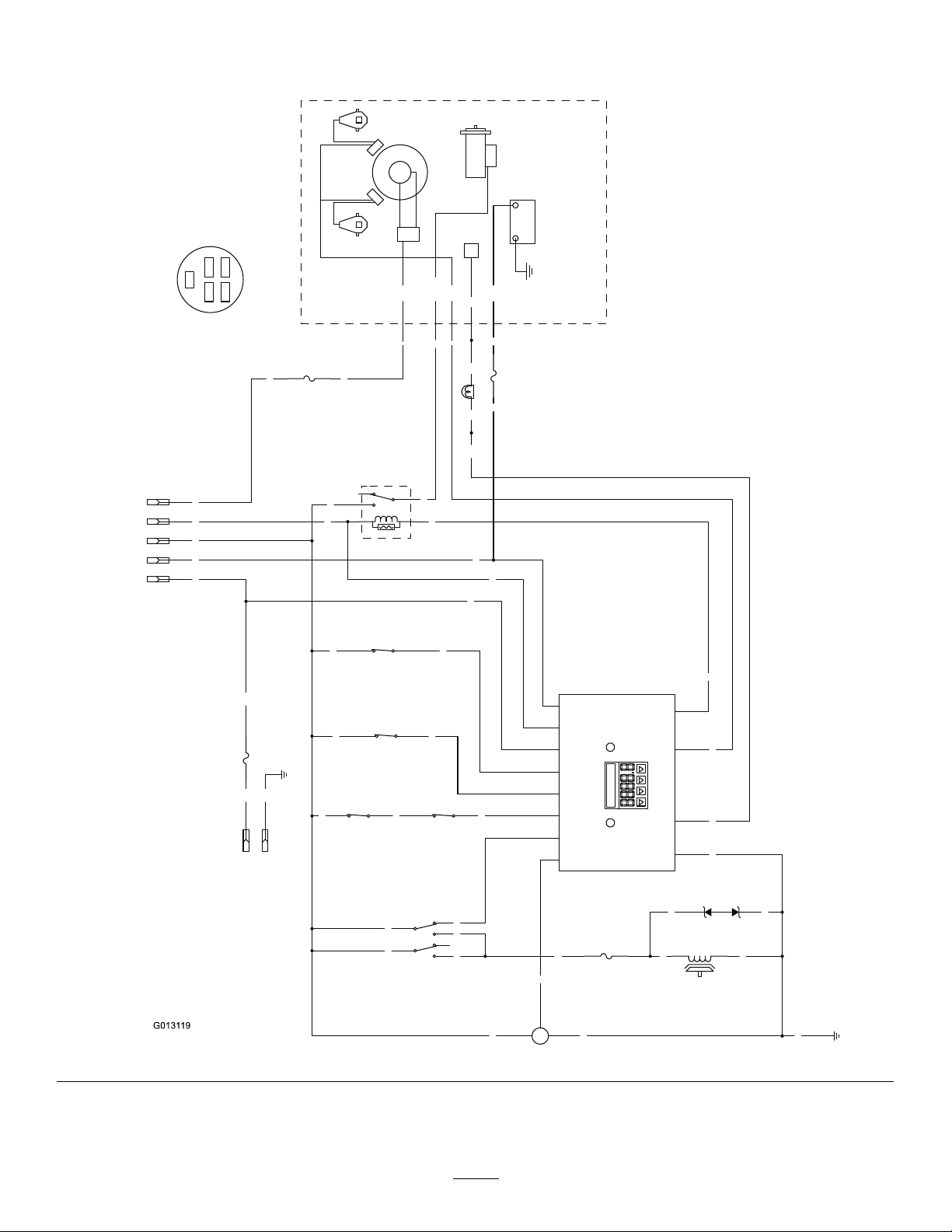
Schematics
G0131 19
BN
BN
BU
BK
Y
W
T
PK
BN
PK
OR
GN
S R
PK PK
PK
LTGR
GY
GY
PK
V
BN
V
OR
GN
OR
R
PK R BK
T
R
BK
GND
PK
BK
BN
BN
BK PK
BK
GND
15A
F4
GY
R
IBA
W
V
BU
V
V
BK
+
S
-
FUEL SENDER
10A
F3
(BRAKE)
SW6
PK
OR
R
F2
25A
PTO
CLUTCH
BU
1
2
5
4
7
8
(PTO SWITCH)
SW2
25A
LAMP
F1
(SEAT)
SW7
2
3
5
4
1
K2
(START RELAY)
TVS DIODE
U2
(NEUT_R)
SW5
B+
MAG
ECU
REG
START
AC
STARTER
+-
AC
IGNITION
MODULES
SPARK PLUGSPARK PLUG
KOHLER EFI
(NEUT_L)
SW4
12
B+
10
KEY_S
9
KEY_A
4
SEAT
11
BRAKE
2
NEUTRAL
3
PTO
5
FUEL
1
START_RELAY
7
MAGNETO
6
FUEL_SOLENOID
8
GROUND
HOUR METER
2
R A
I
A
4
7
1 3
6
5
A
3
SW1
1
B
B
C
B
8
2
4
5
(IGNITION)
6
5
1
KEY SW
OPTIONAL
ACCESSORIES
2
S
Ignition switch terminal locations
viewed from back
OFF = no connections
ON = BRIA
START = BRIS
BK = BLACK
BN = BROWN
BU = BLUE
GN = GREEN
GY = GREY
LT GR = LIGHT GREEN
OR = ORANGE
PK = PINK
R = RED
T = T
AN
V = VIOLET
W = WHITE
WireDiagram(Rev .A)
69
Page 70

Notes:
70
Page 71

Notes:
71
Page 72

TheToroTotalCoverageWarranty
ALimitedWarranty(seewarrantyperiodsbelow)Contractor
Landscape
Equipment
(LCE)
ConditionsandProductsCovered
TheT oroCompanyanditsafliate,T oroWarrantyCompany ,pursuanttoanagreement
betweenthem,jointlypromisetotheoriginalpurchasertorepairtheT oroProducts
listedbelowifdefectiveinmaterialsorworkmanship.
Thefollowingtimeperiodsapplyfromthedateofpurchasebytheoriginalowner:
ProductsWarrantyPeriod
21in.Mowers2yearsResidentialUse
1yearCommercialUse
4
•Engines
Honda–2years
Kawasaki–3years
30in.Mowers2yearsResidentialUse
1yearCommercialUse
4
•Engines
Mid-SizeWalk-BehindMowers
4
•Engines
GrandStand
4
•Engines
•Frame
®
ZMaster
•Engines
2000SeriesMowers
4
•Frame
®
ZMaster
•Engines
•Frame
ZMaster
•Engines
4
®
4
3000SeriesMowers
5000SeriesMowers
®
Mowers
Kawasaki–3years
2years
Kawasaki–3years
5yearsor1,200hours
3years
Lifetime(originalowneronly)
4yearsor500hours
3years
Lifetime(originalowneronly)
5yearsor1,200hours
3years
Lifetime(originalowneronly)
5yearsor1,200hours
KohlerCommand–2years
KohlerEFI–3years
•Frame
®
ZMaster
•Engines
6000SeriesMowers
4
•Frame
®
ZMaster
•Engines
7000SeriesMowers
4
•Frame
Lifetime(originalowneronly)
5yearsor1,200hours
Kawasaki–3years
Lifetime(originalowneronly)
5yearsor1,200hours
2years
Lifetime(originalowneronly)
AllMowers
•Battery90daysPartsandLabor
1yearPartsonly
•BeltsandTires90days
•Attachments1year
1
Residentialusemeansuseoftheproductonthesamelotasyourhome.Useatmorethanone
locationisconsideredcommercialuseandthecommercialwarrantywouldapply .
2
Whicheveroccursrst.
3
LifetimeFrameWarranty-Ifthemainframe,consistingofthepartsweldedtogethertoformthe
tractorstructurethatothercomponentssuchastheenginearesecuredto,cracksorbreaksin
normaluse,itwillberepairedorreplaced,atT oro'soption,underwarrantyatnocostforpartsand
labor.Framefailureduetomisuseorabuseandfailureorrepairrequiredduetorustorcorrosion
arenotcovered.
4
SomeenginesusedonT oroProductsarewarrantedbytheenginemanufacturer .
1
1
2
3
2
3
2
3
2
3
2
3
2
3
InstructionsforObtainingWarrantyService
IfyouthinkthatyourT oroProductcontainsadefectinmaterialsorworkmanship,
followthisprocedure:
1.ContactanyAuthorizedT oroServiceDealertoarrangeserviceattheir
dealership.T olocateadealerconvenienttoyou,refertotheY ellowPagesof
yourtelephonedirectory(lookunder“LawnMowers”)oraccessourwebsite
atwww.Toro.com.Y oumayalsocallthenumberslistedinitem#3tousethe
24-hourT oroDealerlocatorsystem.
2.Bringtheproductandyourproofofpurchase(salesreceipt)totheService
Dealer.Thedealerwilldiagnosetheproblemanddetermineifitiscovered
underwarranty.
3.IfforanyreasonyouaredissatisedwiththeServiceDealer’sanalysisorwith
theassistanceprovided,contactusat:
RLCCustomerCareDepartment
ToroWarrantyCompany
811 1LyndaleAvenueSouth
Bloomington,MN55420-1 196
888-865-5676(U.S.Customers)
888-865-5691(Canadacustomers)
OwnerResponsibilities
YoumustmaintainyourT oroProductbyfollowingthemaintenanceprocedures
describedintheOperator'sManual.Suchroutinemaintenance,whetherperformedby
adealerorbyyou,isatyourexpense.
ItemsandConditionsNotCovered
Thereisnootherexpresswarrantyexceptforspecialemissionsystemcoverage
andenginewarrantycoverageonsomeproducts.Thisexpresswarrantydoesnot
coverthefollowing:
•Costofregularmaintenanceserviceorparts,suchaslters,fuel,lubricants,oil
changes,sparkplugs,airltersbladesharpeningorwornblades,cable/linkage
adjustments,orbrakeandclutchadjustments
•Componentsfailingduetonormalwear
•Anyproductorpartwhichhasbeenalteredormisusedorneglectedandrequires
replacementorrepairduetoaccidentsorlackofpropermaintenance
•Pickupanddeliverycharges
•RepairsorattemptedrepairsbyanyoneotherthananAuthorizedT oroService
Dealer
•Repairsnecessaryduetofailuretofollowrecommendedfuelprocedure(consult
Operator'sManualformoredetails)
–Removingcontaminantsfromthefuelsystemisnotcovered
–Useofoldfuel(morethanonemonthold)orfuelwhichcontainsmorethan
10%ethanolormorethat15%MTBE
–Failuretodrainthefuelsystempriortoanyperiodofnon-useoverone
month
GeneralConditions
AllrepairscoveredbythesewarrantiesmustbeperformedbyanAuthorizedT oro
ServiceDealerusingT oroapprovedreplacementparts.
NeitherTheToroCompanynorToroWarrantyCompanyisliableforindirect,
incidentalorconsequentialdamagesinconnectionwiththeuseoftheToro
Productscoveredbythiswarranty ,includinganycostorexpenseofproviding
substituteequipmentorserviceduringreasonableperiodsofmalfunctionor
non-usependingcompletionofrepairsunderthiswarranty.
Allimpliedwarrantiesofmerchantability(thattheproductistforordinaryuse)
andtnessforuse(thattheproductistforaparticularpurpose)arelimitedto
thedurationoftheexpresswarranty.
Somestatesdonotallowexclusionsofincidentalorconsequentialdamages,
orlimitationsonhowlonganimpliedwarrantylasts,sotheaboveexclusions
andlimitationsmaynotapplytoyou.
Thiswarrantygivesyouspeciclegalrights,andyoumayalsohaveotherrights
whichvaryfromstatetostate.
CountriesOtherthantheUnitedStatesorCanada
CustomerswhohavepurchasedT oroproductsoutsidetheUnitedStatesorCanadashouldcontacttheirT oroDistributor(Dealer)toobtainguaranteepoliciesforyourcountry,
province,orstate.IfforanyreasonyouaredissatisedwithyourDistributor'sserviceorhavedifcultyobtainingguaranteeinformation,contacttheT oroimporter.Ifallother
remediesfail,youmaycontactusatT oroWarrantyCompany .
AustralianConsumerLaw:AustraliancustomerswillnddetailsrelatingtotheAustralianConsumerLaweitherinsidetheboxoratyourlocalT oroDealer.
374-0252RevF
 Loading...