

Page 1
FormNo.3396-343RevB
TimeCutter
®
SWX5050Riding
Mower
ModelNo.74797—SerialNo.315000001andUp
Registeratwww.T oro.com.
OriginalInstructions(EN)
*3396-343*B
Page 2
WARNING
Introduction
CALIFORNIA
Proposition65Warning
Thisproductcontainsachemical
orchemicalsknowntotheStateof
Californiatocausecancer,birthdefects,
orreproductiveharm.
Theengineexhaustfromthisproduct
containschemicalsknowntotheStateof
Californiatocausecancer,birthdefects,
orotherreproductiveharm.
Important:Thisengineisnotequippedwith
asparkarrestermufer.Itisaviolationof
CaliforniaPublicResourceCodeSection4442to
useoroperatetheengineonanyforest-covered,
brush-covered,orgrass-coveredland.Other
statesorfederalareasmayhavesimilarlaws.
ThissparkignitionsystemcomplieswithCanadian
ICES-002
WARNING
Removingstandardoriginalequipmentparts
andaccessoriesmayalterthewarranty,
traction,andsafetyofthemachine.Failureto
useoriginalT oropartscouldcauseserious
injuryordeath.Makingunauthorizedchanges
totheengine,fuelorventingsystem,may
violateEPAandCARBregulations.
Thismachineisaride-on,rotary-bladelawnmower
intendedtobeusedbyhomeownersinresidential
applications.Itisprimarilydesignedforcuttinggrass
onwell-maintainedlawns.Itisnotdesignedforcutting
brush,mowinggrassandothergrowthalongside
highways,orforagriculturaluses.
Readthisinformationcarefullytolearnhowtooperate
andmaintainyourproductproperlyandtoavoid
injuryandproductdamage.Youareresponsiblefor
operatingtheproductproperlyandsafely .
YoumaycontactTorodirectlyatwww.Toro.com
forproductsafetyandoperationtrainingmaterials,
accessoryinformation,helpndingadealer,orto
registeryourproduct.
Wheneveryouneedservice,genuineToroparts,or
additionalinformation,contactanAuthorizedService
DealerorToroCustomerServiceandhavethemodel
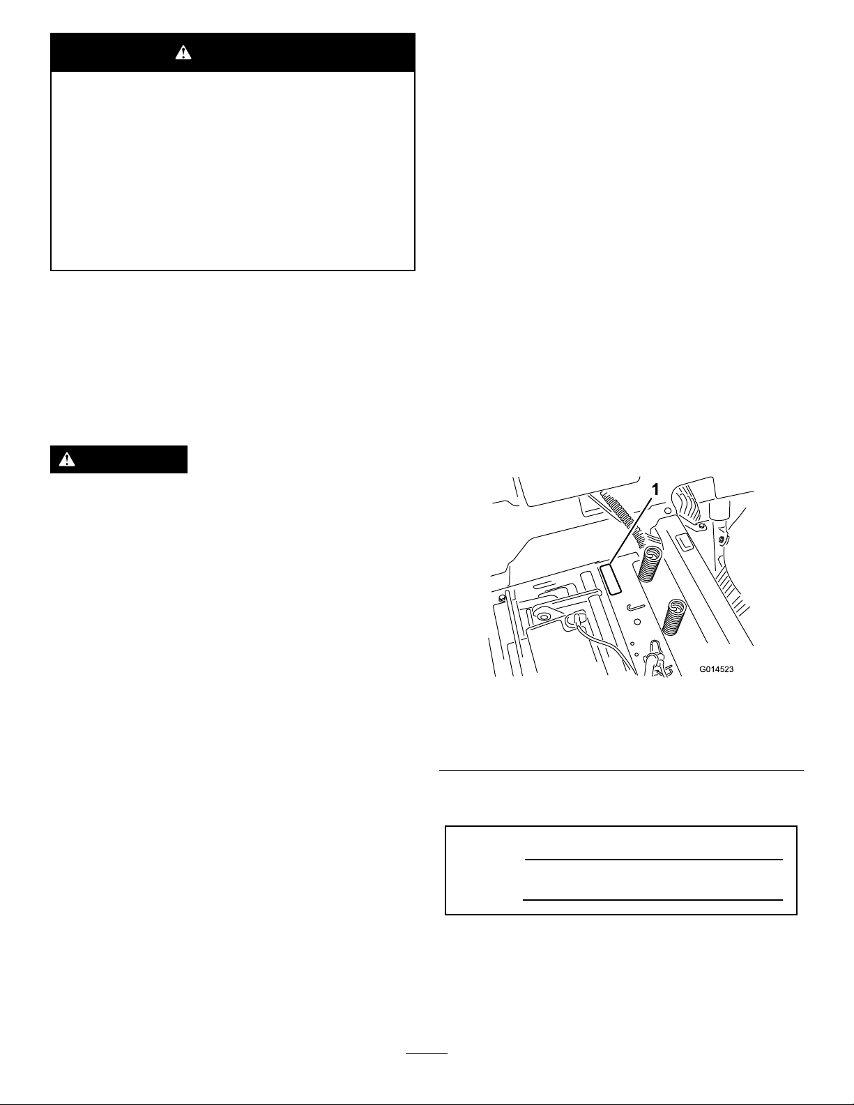
andserialnumbersofyourproductready.Figure1
identiesthelocationofthemodelandserialnumbers
ontheproduct.Writethenumbersinthespace
provided.
Replaceallpartsincluding,butnotlimited
to,tires,belts,blades,andfuelsystem
componentswithoriginalToroparts.
TheenclosedEngineOwner'sManualis
suppliedforinformationregardingtheUS
EnvironmentalProtectionAgency(EPA)and
theCaliforniaEmissionControlRegulationof
emissionsystems,maintenance,andwarranty.
Replacementsmaybeorderedthroughtheengine
manufacturer.
GrossHorsepower
Thegrossornethorsepowerofthisenginewas
laboratoryratedbytheenginemanufacturerin
accordancewiththeSocietyofAutomotiveEngineers
(SAE)J1940.Asconguredtomeetsafety,emission,
andoperatingrequirements,theactualenginetorque
onthisclassofmowerwillbesignicantlylower.
Gotowww.Toro.comtoviewspecicationsonyour
mowermodel.
g014523
Figure1
Undertheseat
1.Modelandserialnumberplate
Writetheproductmodelandserialnumbersinthe
spacebelow:
ModelNo.
SerialNo.
Thismanualidentiespotentialhazardsandhas
safetymessagesidentiedbythesafetyalertsymbol
(Figure2),whichsignalsahazardthatmaycause
seriousinjuryordeathifyoudonotfollowthe
recommendedprecautions.
©2017—TheToro®Company
8111LyndaleAvenueSouth
Bloomington,MN55420
Contactusatwww.Toro.com.
2
PrintedintheUSA
AllRightsReserved
Page 3

Figure2
1.Safetyalertsymbol.
Thismanualuses2wordstohighlightinformation.
Importantcallsattentiontospecialmechanical
informationandNoteemphasizesgeneralinformation
worthyofspecialattention.
Contents
Safety.......................................................................4
SafeOperatingPractices....................................4
ToroRidingMowerSafety...................................6
SlopeIndicator...................................................7
SafetyandInstructionalDecals..........................8
ProductOverview...................................................13
Controls...........................................................13
Operation................................................................15
AddingFuel......................................................15
CheckingtheEngine-OilLevel..........................16
BreakinginaNewMachine..............................16
ThinkSafetyFirst..............................................16
StartingtheEngine...........................................18
OperatingtheParkingBrake
(SmartPark
OperatingtheBlades........................................19
StoppingtheEngine.........................................19
DrivingtheMachine..........................................19
StoppingtheMachine.......................................20
MowinginReverse...........................................20
AdjustingtheHeight-of-Cut...............................21
PositioningtheSteeringWheel.........................21
AdjustingtheAnti-ScalpRollers........................22
PositioningtheSeat..........................................22
PushingtheMachinebyHand..........................22
GrassDeector................................................23
TransportingtheMachine.................................23
LoadingtheMachine........................................24
OperatingTips.................................................25
Maintenance...........................................................27
RecommendedMaintenanceSchedule(s)...........27
Pre-MaintenanceProcedures..............................28
RaisingtheSeat...............................................28
RaisingtheFrontoftheMachine.......................28
Lubrication..........................................................28
GreasingtheBearings......................................28
EngineMaintenance...........................................29
ServicingtheAirCleaner..................................29
ServicingtheEngineOil....................................30
ServicingtheSparkPlug...................................32
CleaningtheCoolingSystem............................33
FuelSystemMaintenance...................................34
™
)................................................19
ReplacingtheIn-LineFuelFilter.......................34
ElectricalSystemMaintenance...........................35
g000502
ChargingtheBattery.........................................35
ServicingtheFuses..........................................36
DriveSystemMaintenance..................................37
CheckingtheTirePressure...............................37
ReleasingtheElectricBrake.............................37
HydraulicSystemMaintenance...........................38
CheckingtheHydraulicOilLevel......................38
ChangingtheHydraulicSystemOiland
Filters............................................................38
MowerMaintenance.............................................40
ServicingtheCuttingBlades.............................40
LevelingtheMowerDeck..................................43
RemovingtheMower........................................44
MowerBeltMaintenance..................................45
InstallingtheMower..........................................46
ReplacingtheGrassDeector..........................46
Cleaning..............................................................48
CleaningundertheFrontoftheMachine...........48
WashingtheUndersideoftheMower
Deck..............................................................48
Storage...................................................................49
CleaningandStorage.......................................49
Troubleshooting......................................................50
Schematics.............................................................52
3
Page 4

Safety
Toreducethepotentialforinjury,comply
withthesesafetyinstructionsandalwayspay
attentiontothesafetyalertsymbol,whichmeans
CAUTION,WARNING,orDANGER-"personal
safetyinstruction."Failuretocomplywiththe
instructionmayresultinpersonalinjuryordeath.
SafeOperatingPractices
Thisproductiscapableofamputatinghandsand
feetandthrowingobjects.Alwaysfollowallsafety
instructionstoavoidseriousinjuryordeath.
ThefollowinginstructionsareadaptedfromANSI
standardB71.1-2012.Allthelanguagewithinthis
ANSIstandardappliestothismachine;however,
duetotheapplicationofthestandardacrossmany
differenttypesofproductssomestatementscan
seemgeneralormisleading.Intheseinstances,T oro
hasrenedthestatementtoconveythemeaningof
thestandardwhilebettermatchingtheproductthis
Operator'sManualpertains.Safetyinformationin
additiontotheinstructionsfoundintheANSIstandard
belowcanbefoundinToroRidingMowerSafetyat
theendofthissection.
GeneralOperation
•Read,understand,andfollowallinstructionsin
theoperator'smanualandonthemachinebefore
starting.
•Donotplacehandsorfeetnearrotatingpartsor
underthemachine.Keepclearofthedischarge
openingatalltimes.
•Allowonlyresponsibleadultswhoarefamiliarwith
theinstructionstooperatethemachine.
•Cleartheareaofobjectssuchasrocks,toys,wire,
etc.,whichcouldbepickedupandthrownbythe
blade.
•Besuretheareaisclearofotherpeoplebefore
mowing.Stopthemachineifanyoneentersthe
area.
•Nevercarrypassengers.
•Donotmowinreverseunlessabsolutely
necessary.Alwayslookdownandbehindbefore
andwhilebackingup.
•Beawareofthemowerdischargedirectionanddo
notpointitatanyone.Avoiddischargingmaterial
againstawallorobstruction.Materialmayricochet
backtowardtheoperator.Stoptheblade(s)when
crossinggravelsurfaces.
•Donotoperatethemachinewithoutdeector,
dischargecoverorentiregrasscollectionsystem
inplaceandworking.
•Bealert,slowdownandusecautionwhenmaking
turns.Lookbehindandtothesidebeforechanging
directions.
•Neverleavearunningmachineunattended.
Alwaysturnoffblades,setparkingbrake,stop
engine,andremovekeybeforedismounting.
•Turnoffbladeswhennotmowing.Stoptheengine,
waitforallpartstocometoacompletestopand
removethekeybeforecleaningthemachine,
removingthegrasscatcheroruncloggingthe
dischargechute.
•Operatethemachineonlyindaylightorgood
articiallight.
•Donotoperatethemachinewhileunderthe
inuenceofalcoholordrugs.
•Watchfortrafcwhenoperatingnearorcrossing
roadways.
•Useextracarewhenloadingorunloadingthe
machineintoatrailerortruck.
•Alwaysweareyeprotectionwhenoperatingthe
mower.
•Dataindicatesthatoperators,age60yearsand
above,areinvolvedinalargepercentageofriding
mower-relatedinjuries.Operatorsshouldevaluate
theirabilitytooperatetheridingmowersafely
enoughtoprotectthemselvesandothersfrom
seriousinjury.
•Alwaysfollowtherecommendationsforany
applicationofcounterweights.
•Lightningcancausesevereinjuryordeath.If
lightningisseenorthunderisheardinthearea,do
notoperatethemachine;seekshelter.
SlopeOperation
Slopesareamajorfactorrelatedtolossofcontroland
tip-overaccidents,whichcanresultinsevereinjuryor
death.Operationonallslopesrequiresextracaution.
Ifyoucannotbackuptheslopeorifyoufeeluneasy
onit,donotmowit.
•Donotmowslopesgreaterthan15degrees.
•Watchforditches,holes,rocks,dips,andrises
thatchangetheoperatingangle,asroughterrain
couldoverturnthemachine.
•Choosealowgroundspeedsoyouwillnothave
tostopwhileoperatingonaslope.
•Donotmowslopeswhengrassiswet.Slippery
conditionsreducetractionandcouldcausesliding
andlossofcontrol.
•Alwayskeepthedrivewheelsengagedwhen
goingdownslopes.Donotshifttoneutraland
coastdownhill.
•Reducespeedanduseextremecautiononslopes.
4
Page 5

•Donotmakesuddenturnsorrapidspeedchanges.
•Removeormarkobstaclessuchasrocks,tree
limbs,etc.fromthemowingarea.Tallgrasscan
hideobstacles.
•Avoidsuddenstartswhenmowinguphillbecause
themowermaytipbackwards.
•Beawarethatlossoftractionmayoccurgoing
downhill.Weighttransfertothefrontwheels
maycausedrivewheelstoslipandcauselossof
brakingandsteering.
•Alwaysavoidsuddenstartingorstoppingona
slope.Iftireslosetraction,stopthemachine,
disengagethebladesandproceedslowlyoffthe
slope.
•Useextremecarewithgrasscatchersorother
attachments.Thesecanchangethestabilityofthe
machineandcauselossofcontrol.
•Donottrytostabilizethemachinebyputtingyour
footontheground.
•Donotmowneardrop-offs,ditches,steepbanks
orwater.Wheelsdroppingoveredgescancause
rollovers,whichmayresultinseriousinjury,death
ordrowning.
•Useawalkbehindmowerand/orahandtrimmer
neardrop-offs,ditches,steepbanksorwater.
TowingSafety
•Donotattachtowedequipmentexceptatthehitch
point.
•Followtheattachmentmanufacturer's
recommendationforweightlimitsfortowed
equipmentandtowingonslopes.Towedweight
mustnotexceedtheweightofthemachine,
operator,andballast.Usecounterweightsor
wheelweightsasdescribedintheattachment,or
inthepullingmachineOperator’sManual.
•Neverallowchildrenorothersinorontowed
equipment.
•Onslopes,theweightofthetowedequipmentmay
causelossoftraction,increasedriskofrollover,
andlossofcontrol.Reducethetowedweightand
slowdown.
•Stoppingdistanceincreaseswiththeweightofthe
towedload.Travelslowlyandallowextradistance
tostop.
•Makewideturnstokeeptheattachmentclearof
themachine.
Service
SafeHandlingofGasoline:
Children
Tragicaccidentscanoccuriftheoperatorisnot
alerttothepresenceofchildren.Childrenareoften
attractedtothemachineandthemowingactivity.
Neverassumethatchildrenwillremainwhereyou
lastsawthem.
•Keepchildrenoutofthemowingareaandunder
thewatchfulcareofanotherresponsibleadult,not
theoperator.
•Bealertandturnthemachineoffifchildrenenter
thearea.
•Beforeandwhilebackingorchangingdirection,
lookbehind,down,andside-to-sideforsmall
children.
•Nevercarrychildren,evenwiththebladesoff.
Theymayfalloffandbeseriouslyinjuredor
interferewithsafemachineoperation.
•Childrenwhohavebeengivenridesinthepast
maysuddenlyappearinthemowingareafor
anotherrideandberunoverorbackedoverby
themower.
•Neverallowchildrentooperatethemachine.
•Useextracarewhenapproachingblindcorners,
shrubs,trees,theendofafenceorotherobjects
thatmayobscurevisionorblockyourviewofa
child.
Toavoidpersonalinjuryorpropertydamage,use
extracarewhenhandlinggasolineandotherfuels.
Theyareammableandthevaporsareexplosive.
•Extinguishallcigarettes,cigars,pipesandother
sourcesofignition.
•Useonlyanapprovedfuelcontainer.
•Neverremovethegascaporaddfuelwhenthe
engineisrunning.Allowtheenginetocoolbefore
refueling.
•Neverrefuelthemachineindoors.
•Neverstorethemachineorfuelcontainerinside
wherethereisanopename,suchasneara
waterheaterorfurnace.
•Neverllcontainersinsideavehicleorona
truckortrailerwithaplasticliner.Alwaysplace
containersonthegroundawayfromyourvehicle
beforelling.
•Removegas-poweredequipmentfromthetruck
ortrailerandrefuelitontheground.Ifthisis
notpossible,thenrefuelsuchequipmentwitha
portablecontainer,ratherthanfromagasoline
dispensernozzle.
•Keepthenozzleincontactwiththerimofthefuel
tankorcontaineropeningatalltimesuntilthe
fuelingiscomplete.Donotuseanozzlelock-open
device.
5
Page 6

•Iffuelisspilledonclothing,changeclothing
immediately.
mowerandanymovingpartswhileengineis
running.
•Neveroverllthefueltank.Replacegascapand
tightensecurely.
GeneralService:
•Neveroperateamachineinsideaclosedarea.
Engineexhaustcontainscarbonmonoxide,which
isanodorless,deadlypoisonthatcankillyou.
•Keepnutsandboltstight,especiallytheblade
attachmentbolts.Keepequipmentingood
condition.
•Neverinterferewiththeintendedfunctionofa
safetydeviceorreducetheprotectionprovided
byasafetydevice.Checktheirproperoperation
regularly.
•Keepthemachinefreeofgrass,leaves,orother
debrisbuild-up.Cleanupoilorfuelspillage.Allow
themachinetocoolbeforestoring.
•Stopandinspecttheequipmentifyoustrikean
object.Repair,ifnecessary,beforerestarting.
•Nevermakeanyadjustmentsorrepairswiththe
enginerunning.
•Grasscatchercomponentsaresubjecttowear,
damageanddeterioration,whichcouldexpose
movingpartsorallowobjectstobethrown.
Frequentlycheckcomponentsandreplace
withmanufacturers'recommendedparts,when
necessary.
•Donottouchequipmentorattachmentpartswhich
maybehotfromoperation.Allowtocoolbefore
attemptingtomaintain,adjustorservice.
•Batteryacidispoisonousandcancauseburns.
Avoidcontactwithskin,eyes,andclothing.Protect
yourface,eyes,andclothingwhenworkingwitha
battery.
•Batterygasescanexplode.Keepcigarettes,
sparksandamesawayfrombattery .
•UseonlyToroapprovedattachments.Warranty
maybevoidedifusedwithunapproved
attachments.
•Ifloadingthemachineontoatrailerortruck,use
asingle,full-widthramponly.Therampangle
shouldnotexceed15degrees.
•Mowerbladesaresharpandcancut.Wrapthe
blade(s)orwearthickly-paddedgloves,anduse
extracautionwhenservicingthem.
•Checkforproperbrakeoperationfrequently.
Adjustandserviceasrequired.
•Maintainorreplacesafetyandinstructiondecals
asnecessary.
•UseonlygenuineT ororeplacementpartsto
ensurethatoriginalstandardsaremaintained.
ToroRidingMowerSafety
Thefollowinglistcontainssafetyinformationspecic
toT oroproductsorothersafetyinformationthatyou
mustknowthatmaynotbeincludedintheANSI
standards.
•Stoptheengine,movethetractionpedaltoneutral,
disengagetheblade-controlswitch,remove
keybeforeanddisconnectsparkplugwire(s)
performinganyservice,repairs,maintenanceor
adjustments.
•Keephands,feet,hair,andlooseclothingaway
fromattachmentdischargearea,undersideof
6
Page 7
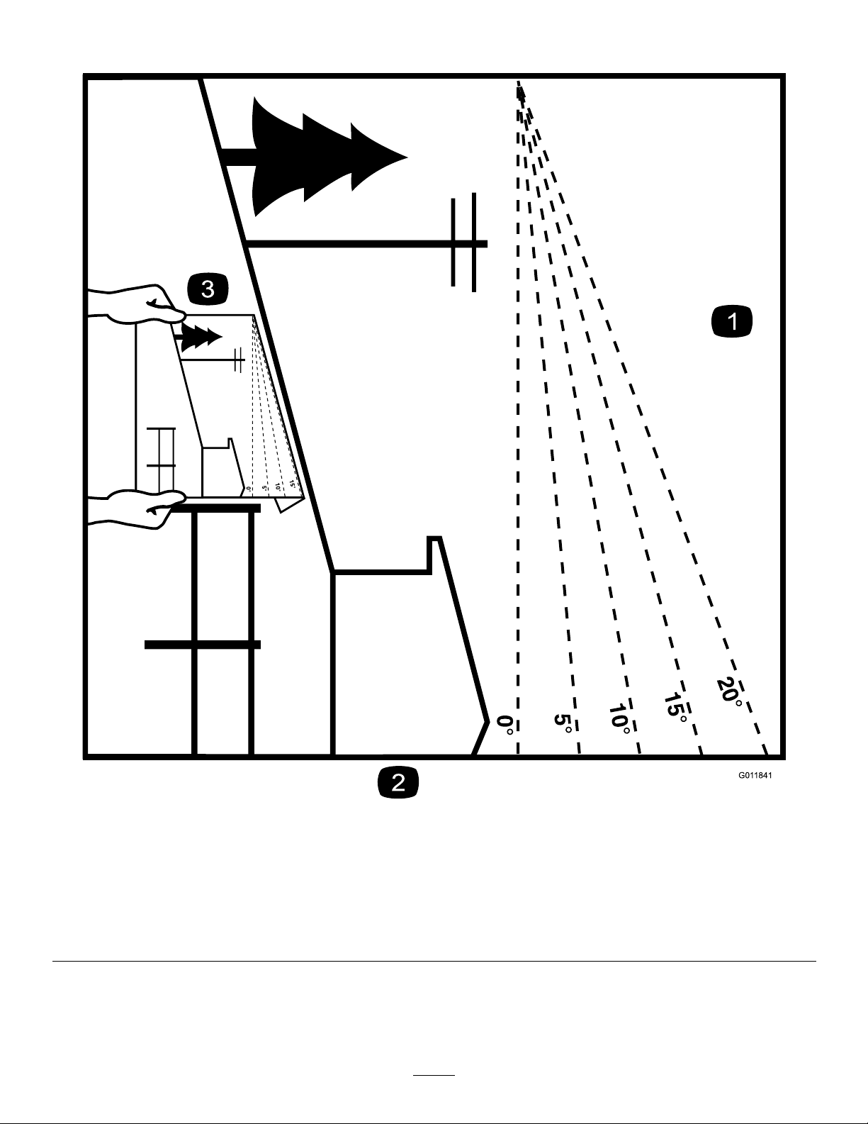
SlopeIndicator
Figure3
Thispagemaybecopiedforpersonaluse.
1.Themaximumslopeyoucansafelyoperatethemachineonis15degrees.Usetheslopecharttodeterminethedegreeofslope
ofhillsbeforeoperating.Donotoperatethismachineonaslopegreaterthan15degrees.Foldalongtheappropriateline
tomatchtherecommendedslope.
2.Alignthisedgewithaverticalsurface,atree,building,fencepole,etc.
3.Exampleofhowtocompareslopewithfoldededge.
7
g011841
Page 8
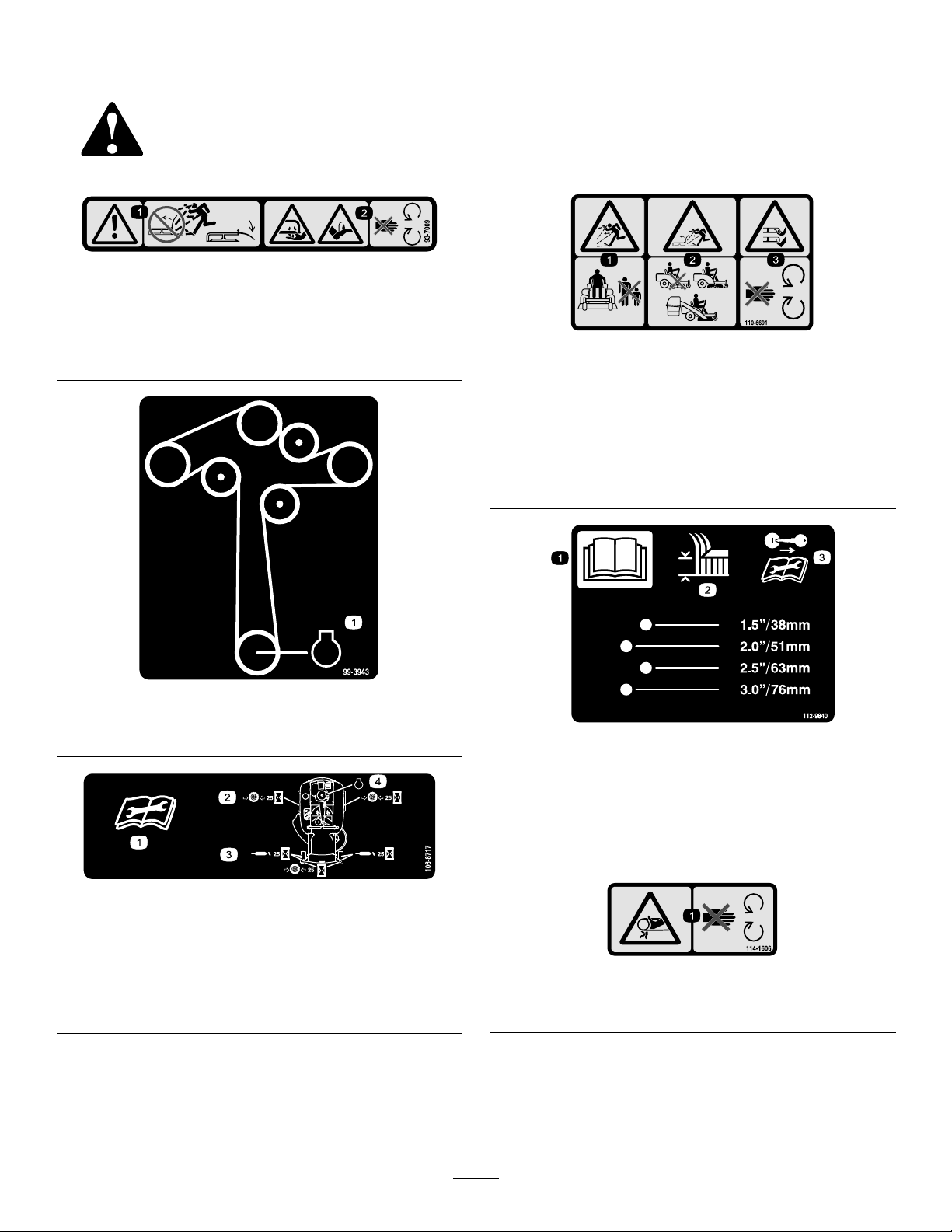
SafetyandInstructionalDecals
Safetydecalsandinstructionsareeasilyvisibletotheoperatorandarelocatednearanyarea
ofpotentialdanger.Replaceanydecalthatisdamagedorlost.
93-7009
1.Warning—don'toperatethemowerwiththedeectorupor
removed;keepthedeectorinplace.
2.Cutting/dismembermenthazardofhandorfoot,mower
blade—stayawayfrommovingparts.
decal93-7009
decal110-6691
110-6691
1.Thrownobjecthazard—keepbystandersasafedistance
fromthemachine.
2.Thrownobjecthazard,mower—donotoperatewithoutthe
deector,dischargecover,orgrasscollectionsystemin
place.
3.Cutting/dismembermentofhandorfoot—stayawayfrom
movingparts.
99-3943
1.Engine
106-8717
1.Readtheinstructionsbeforeservicingorperforming
maintenance.
2.Checktirepressureevery25operatinghours.
3.Greaseevery25operatinghours.
4.Engine
decal99-3943
decal112-9840
112-9840
1.ReadtheOperator's
Manual.
2.Heightofcut
decal106-8717
3.Removetheignitionkey
andreadtheinstructions
beforeservicingor
performingmaintenance.
decal114-1606
114-1606
1.Entanglementhazard,belt—keepallguardsinplace.
8
Page 9
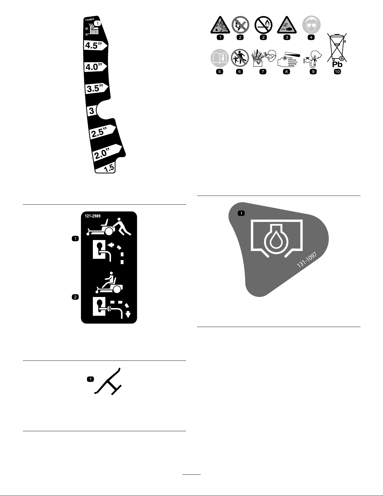
BatterySymbols
Someorallofthesesymbolsareonyourbattery
decalbatterysymbols
1.Explosionhazard
6.Keepbystandersasafe
distancefromthebattery.
2.Nore,opename,or
smoking.
7.Weareyeprotection;
explosivegasescan
causeblindnessandother
injuries
3.Causticliquid/chemical
burnhazard
8.Batteryacidcancause
blindnessorsevereburns.
4.Weareyeprotection9.Flusheyesimmediately
withwaterandgetmedical
decal119-8870
119-8870
5.ReadtheOperator's
Manual.
helpfast.
10.Containslead;donot
discard.
1.Height-of-cut
121-2989
1.Bypassleverpositionfor
pushingthemachine
2.Bypassleverpositionfor
operatingthemachine
Manufacturer'sMark
1.Indicatesthebladeisidentiedasapartfromtheoriginal
machinemanufacturer.
decal131-1097
131-1097
1.Oildrain
decal121-2989b
decaloemmarkt
9
Page 10
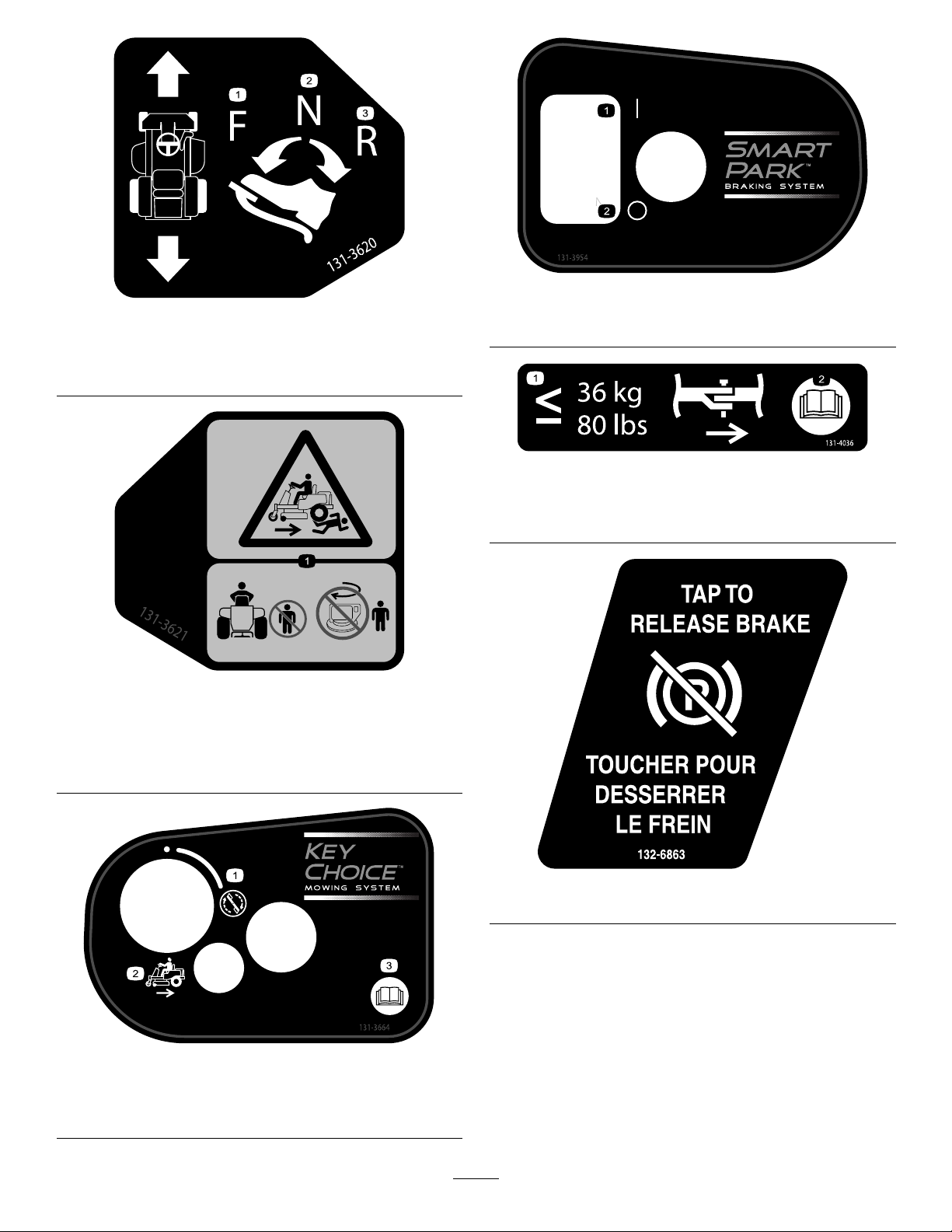
decal131-3954
decal131-3620
131-3620
1.Pedalposition—forward
3.Pedalposition—reverse
1.On2.Off
131-3954
2.Pedalposition—neutral
decal131-4036
131-4036
131-3621
1.Crushing/dismembermenthazardofbystanders—keep
bystandersawayfromthemachine;donotactivateKey
Choiceswitch(allowsmowinginreverse)withbystanders
nearby.
1.Maximumdrawbarpull36
kg(80lb)
decal131-3621b
2.ReadtheOperator's
Manual.
decal132-6863
132-6863
131-3664
1.Spinningblade3.Operator'sManual
2.Reverse
decal131-3664
10
Page 11
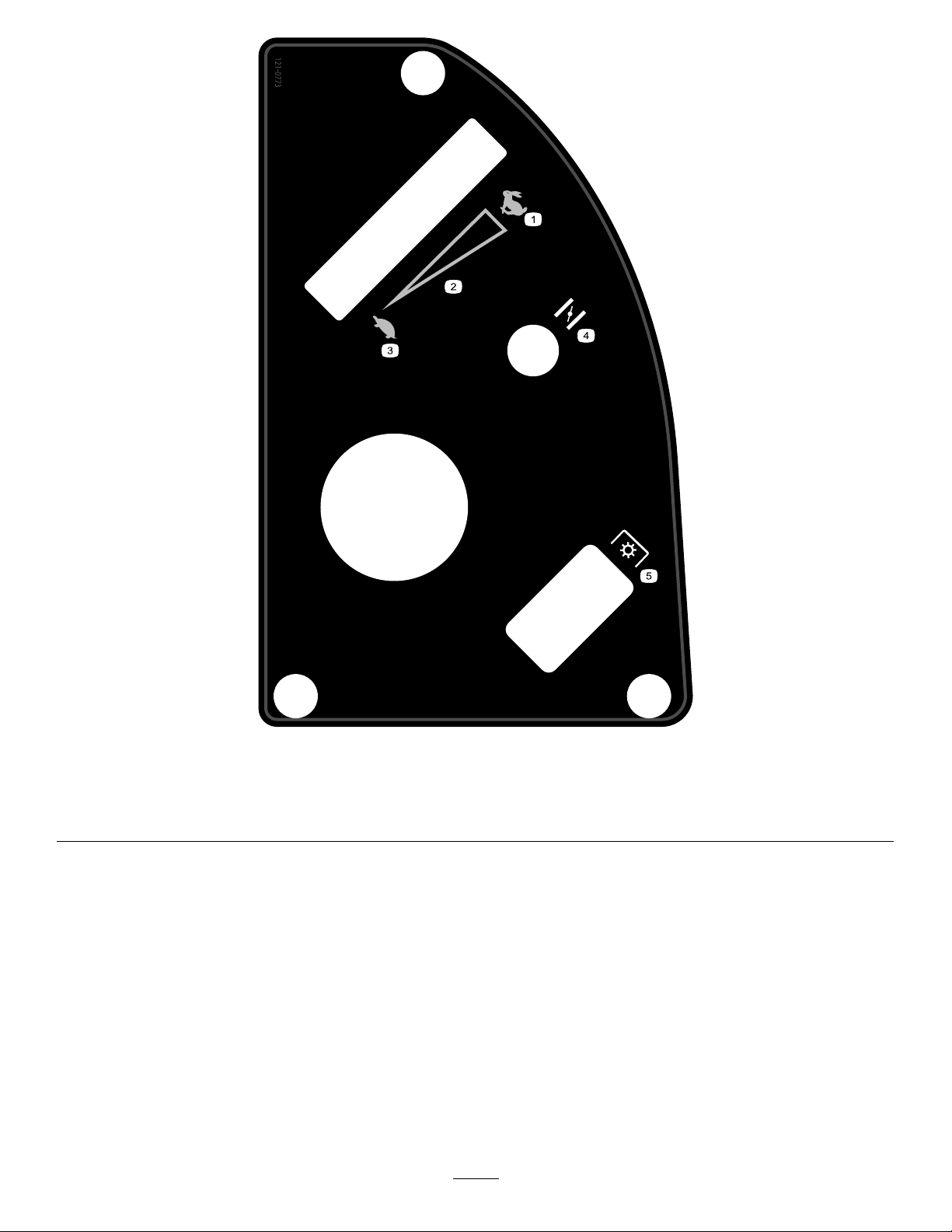
decal121-0773
121-0773
1.Fast
4.Choke
2.Continuousvariablesetting5.Powertake-off(PTO),Bladecontrolswitch
3.Slow
11
Page 12
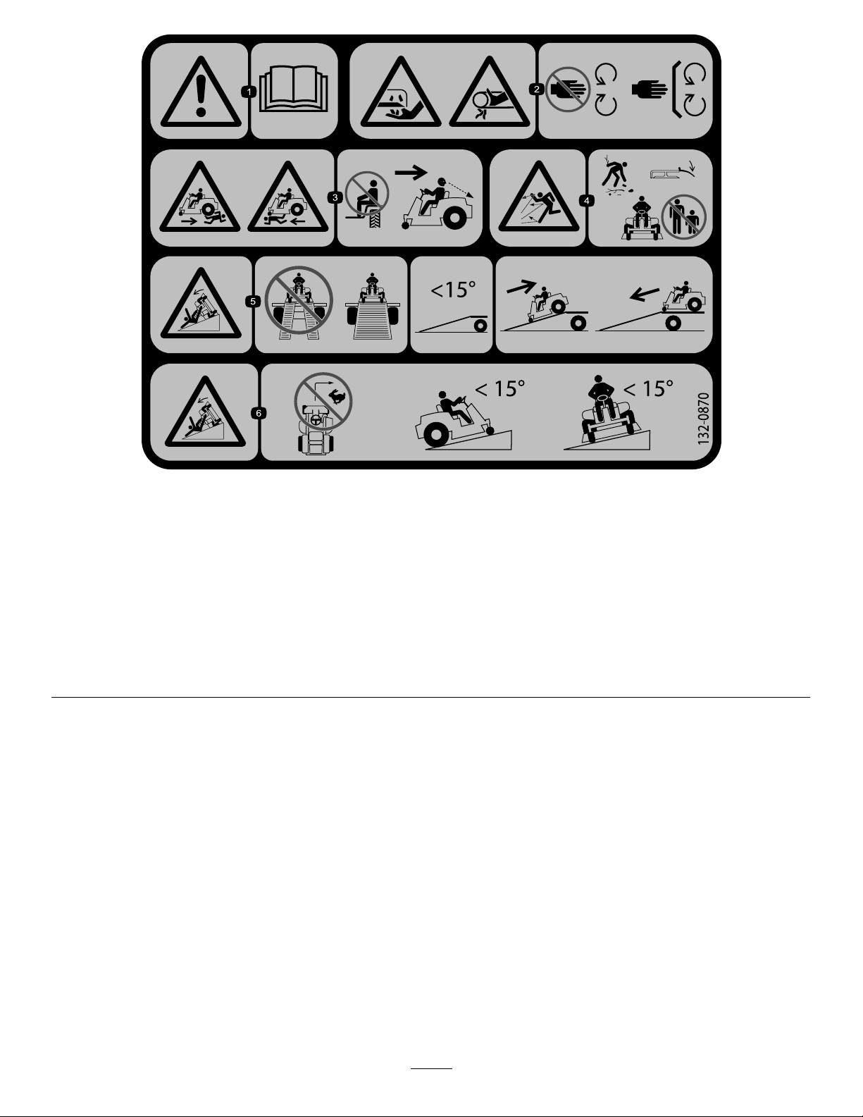
decal132-0870
132-0870
1.Warning—readtheOperator'sManual.
2.Cuttinghazardofhand,mowerblade;
pinchinghazardofhand,belt—keep
handsandfeetawayfrommoving
parts;keepallguardsandshieldsin
place.
3.Bodilyharmhazard—noriders;look
behindyouwhenmowinginreverse.
4.Thrownobjecthazard—keep
bystandersawayfromthemachine;
removedebrisfromtheareabefore
mowing;keepthedeectorshield
down.
5.Ramptippinghazard—whenloading
ontoatrailer,donotusedualramps;
onlyuseasinglerampwideenough
forthemachineandthathasanincline
lessthan15degrees;backupthe
ramp(inreverse)anddriveforwardoff
theramp.
6.Tippinghazardonslopes—donot
makesharp,quickturns;donotuse
slopesgreaterthan15degrees.
12
Page 13
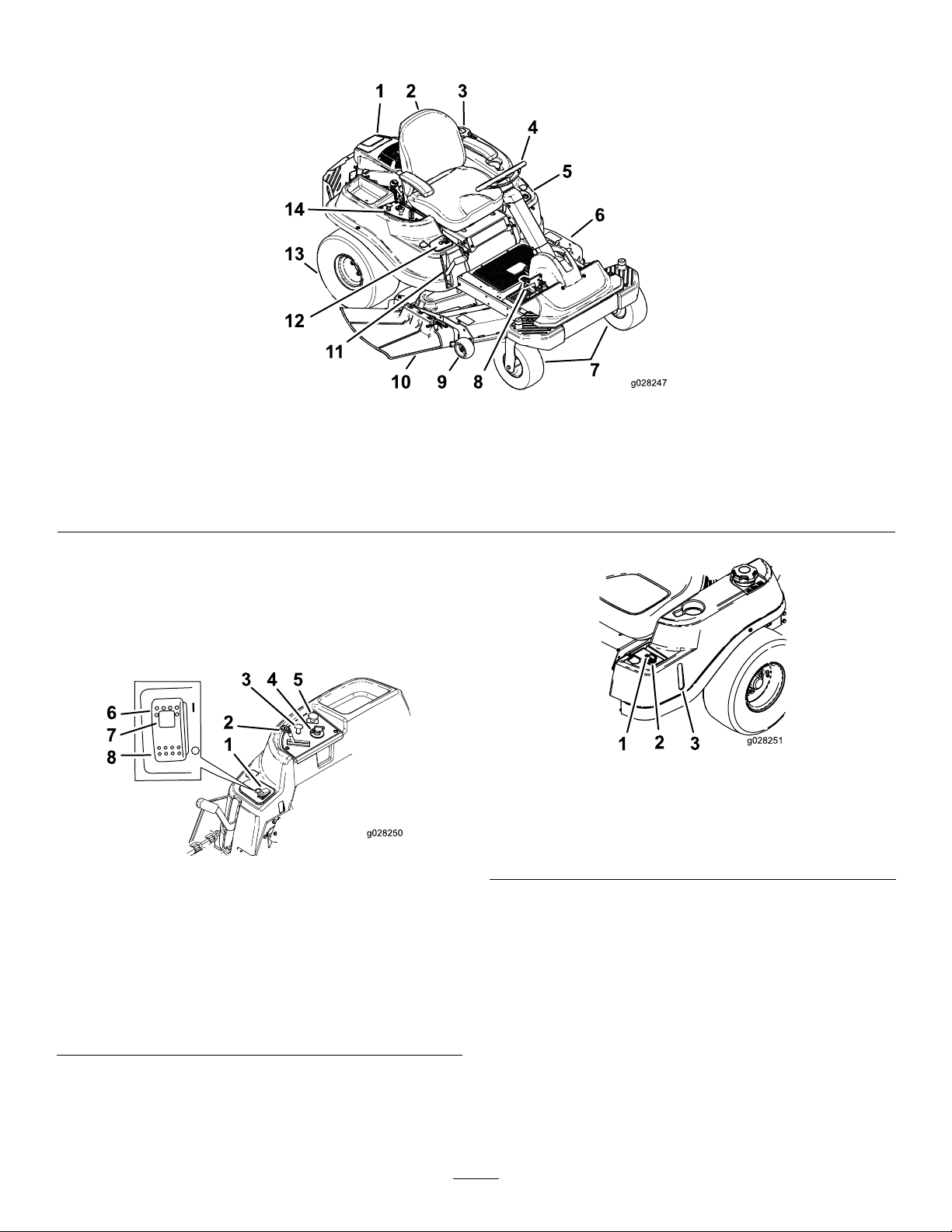
ProductOverview
1.Engine
2.Seat
3.Gastankcap
4.Steeringwheel
5.KeyChoice
6.Mowerdeck
7.Frontcasterwheel
8.Traction-controlpedal
g028247
Figure4
®
control
9.Anti-scalproller13.Reardrivewheel
10.Deector14.Controlpanel
11.Height-of-cutlever
12.SmartPark
™
switch
Controls
BecomefamiliarwithallcontrolsinFigure5and
Figure6beforeyoustarttheengineandoperatethe
machine.
Figure5
ControlPanel
1.Parkingbrakeswitch5.Blade-controlswitch
2.Throttle
3.Choke
4.Ignitionswitch
(powertake-off)
6.Parkingbrake—On
7.Parkingbrakeindicator
light
8.Parkingbrake—Off
g028251
Figure6
1.Operating–in–Reverse
warninglight
2.KeyChoicekey(bluein
g028250
color)
3.Fuel-presencewindow
IgnitionSwitch
Theignitionswitchhas3positions—Off,Runand
Start.ThekeywillturntoStartandmovebacktoRun
uponrelease.TurningthekeytotheOffpositionwill
stoptheengine;however,alwaysremovethekey
whenleavingthemachinetopreventsomeonefrom
accidentallystartingtheengine(Figure5).
13
Page 14

ChokeControl
Usethechoketostartacoldengine.Pullthechoke
knobuptoengageit.Pushdownonthechokeknob
todisengageit(Figure5).
ThrottleControl
ThethrottlecontrolisvariablebetweenFastand
Slow.Movingthrottleleverforwardwillincrease
enginespeedandmovingthrottlelevertotherearwill
decreaseenginespeed(Figure5).
Blade-ControlSwitch(Power
Take-off)
Engagetheparkingbrakebyoneofthefollowing
actions:
•PressingtheSmartPark
(Figure5).
™
switchtotheOnposition
•Theparkingbrakeengagesautomaticallywhen
theoperatorleavestheseatandthetraction
controlpedalisinneutralposition.
•Theparkingbrakeautomaticallyengages5to6
secondsaftertheignitionswitchisturnedtothe
Offposition(ifnotalreadyengaged).
Todisengagetheparkingbrake,presstheSmartpark
switchtotheOffpositionwiththekeyintherun
position.
Theblade-controlswitch,(PTO),engagesand
disengagespowertothemowerblades(Figure5).
Fuel-PresenceWindow
Thefuelwindowlocatedontheleft-handsideof
themachine,canbeusedtoverifythepresenceof
gasolineinthetank(Figure6).
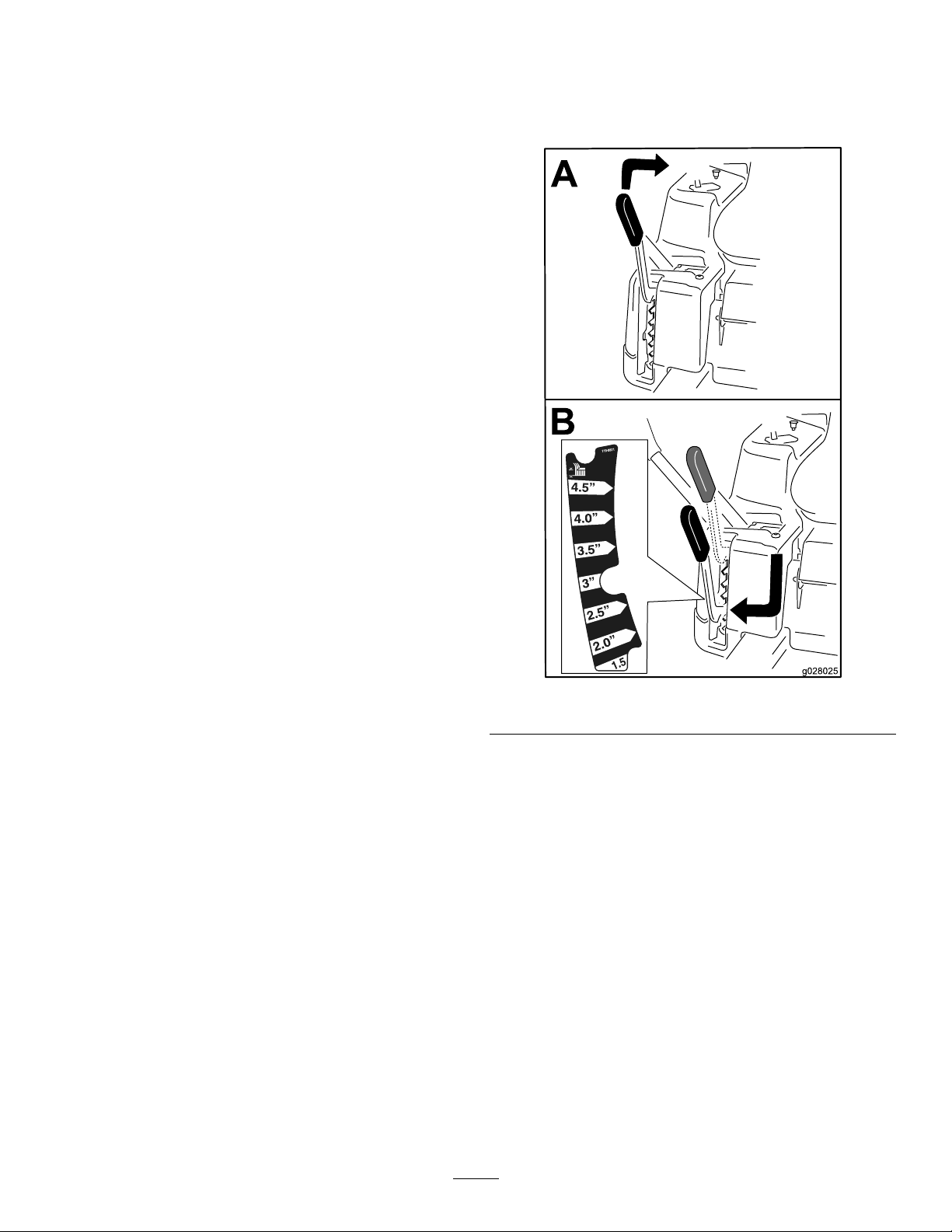
Height-of-CutLever
Theheight-of-cutleverallowsyoutolowerandraise
thedeckfromtheseatedposition.Whenyouraisethe
lever(towardyou),thedeckisraisedfromtheground,
andwhenyoulowerit(awayfromyou),itlowersto
theground.Adjusttheheight-of-cutonlywhilethe
machineisnotmoving(Figure15).
KeyChoice
Thisswitchallowsyoutomowinreversewhenitis
activated.Toactivateit,turntheswitchtoonand
releaseitafterthePTOisengaged.T odeactivateit,
disengagethepowertake-off(PTO)(Figure6).
®
Switch
HourMeter
Thehourmeterrecordsthenumberofhourswhen
theoperatorisintheseatandtheignitionswitchisin
theONposition(Figure7).
g027869
Figure7
1.Hourmeterlocationbehindtheseat
Operating-in-ReverseWarning
Light
TheOperating–in–Reversewarninglightwillilluminate
whenevertheKeyChoicekeyisusedtodeactivatethe
operating–in–reverseinterlock.Itisareminderthat
theinterlocksystemisdeactivated.Thelightgoes
outwheneverthePTOisdisengagedortheengineis
shutoff.Whenthelightison,lookbehindanduse
extracautionwhenbacking.
SmartPark
Theparkingbrakeisactivatedelectronically.
™
Switch
14
Page 15

Operation
Note:Determinetheleftandrightsidesofthe
machinefromthenormaloperatingposition.
AddingFuel
•Forbestresults,useonlyclean,fresh(lessthan
30daysold),unleadedgasolinewithanoctane
ratingof87orhigher((R+M)/2ratingmethod).
•Ethanol:Gasolinewithupto10%ethanol
(gasohol)or15%MTBE(methyltertiarybutyl
ether)byvolumeisacceptable.Ethanoland
MTBEarenotthesame.Gasolinewith15%
ethanol(E15)byvolumeisnotapprovedforuse.
Neverusegasolinethatcontainsmorethan
10%ethanolbyvolume,suchasE15(contains
15%ethanol),E20(contains20%ethanol),orE85
(containsupto85%ethanol).Usingunapproved
gasolinemaycauseperformanceproblemsand/or
enginedamagewhichmaynotbecoveredunder
warranty.
•Donotusegasolinecontainingmethanol.
•Donotstorefueleitherinthefueltankorfuel
containersoverthewinterunlessafuelstabilizer
isused.
•Donotaddoiltogasoline.
DANGER
DANGER
Incertainconditionsduringfueling,static
electricitycanbereleasedcausingaspark
whichcanignitethegasolinevapors.Are
orexplosionfromgasolinecanburnyouand
othersandcandamageproperty.
•Alwaysplacegasolinecontainersonthe
groundawayfromyourvehiclebefore
lling.
•Donotllgasolinecontainersinsidea
vehicleoronatruckortrailerbedbecause
interiorcarpetsorplastictruckbedliners
mayinsulatethecontainerandslowthe
lossofanystaticcharge.
•Whenpractical,removegas-powered
equipmentfromthetruckortrailerand
refueltheequipmentwithitswheelsonthe
ground.
•Ifthisisnotpossible,thenrefuelsuch
equipmentonatruckortrailerfroma
portablecontainer,ratherthanfroma
gasolinedispensernozzle.
•Ifagasolinedispensernozzlemustbe
used,keepthenozzleincontactwiththe
rimofthefueltankorcontaineropeningat
alltimesuntilfuelingiscomplete.
Incertainconditions,gasolineisextremely
ammableandhighlyexplosive.Areor
explosionfromgasolinecanburnyouand
othersandcandamageproperty.
•Fillthefueltankoutdoors,inanopenarea,
whentheengineiscold.Wipeupany
gasolinethatspills.
•Neverllthefueltankinsideanenclosed
trailer.
•Donotllthefueltankcompletelyfull.Add
gasolinetothefueltankuntilthelevelis6
to13mm(1/4to1/2inch)belowthebottom
ofthellerneck.Thisemptyspaceinthe
tankallowsgasolinetoexpand.
•Neversmokewhenhandlinggasoline,and
stayawayfromanopenameorwhere
gasolinefumesmaybeignitedbyaspark.
•Storegasolineinanapprovedcontainer
andkeepitoutofthereachofchildren.
Neverbuymorethana30-daysupplyof
gasoline.
•Donotoperatewithoutentireexhaust
systeminplaceandinproperworking
condition.
WARNING
Gasolineisharmfulorfatalifswallowed.
Long-termexposuretovaporscancause
seriousinjuryandillness.
•Avoidprolongedbreathingofvapors.
•Keepfaceawayfromnozzleandgastank
orconditionerbottleopening.
•Avoidcontactwithskin;washoffspillage
withsoapandwater.
UsingStabilizer/Conditioner
Useafuelstabilizer/conditionerinthemachineto
providethefollowingbenets:
•Keepsgasolinefreshduringstorageof90daysor
less.Forlongerstorageitisrecommendedthat
thefueltankbedrained.
•Cleanstheenginewhileitruns
•Eliminatesgum-likevarnishbuildupinthefuel
system,whichcauseshardstarting
Important:Donotusefueladditives
containingmethanolorethanol.
15
Page 16
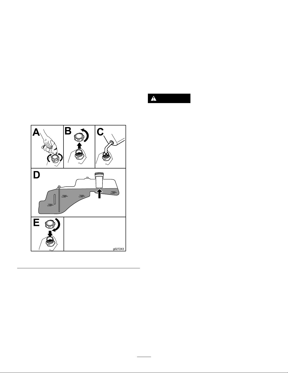
Addthecorrectamountofgasstabilizer/conditioner
tothegas.
Note:Afuelstabilizer/conditionerismosteffective
whenmixedwithfreshgasoline.T ominimizethe
chanceofvarnishdepositsinthefuelsystem,use
fuelstabilizeratalltimes.
new,placingadditionalloadontheengine.Allow
40to50hoursofbreak-intimefornewmachinesto
developfullpowerandbestperformance.
ThinkSafetyFirst
FillingtheFuelTank
Note:Ensurethattheengineisshutoffandthe
motioncontrolsareintheparkedposition.
Note:Y oucanusethefuelwindowtoverifythe
presenceofgasolinebeforellingthetank(Figure8).
Important:Donotoverllfueltank.Fillthefuel
tanktothebottomofthellerneck.Theempty
spaceinthetankallowsthefueltoexpand.
Overllingmayresultinfuelleakage,damageto
theengine,ordamagetotheemissionssystem.
OperatingSafety
Pleasecarefullyreadallofthesafetyinstructionsand
decalsinthesafetysection.Knowingthisinformation
couldhelpyou,yourfamily ,pets,orbystandersavoid
injury.
DANGER
Mowingonwetgrassorsteepslopescan
causeslidingandlossofcontrol.
Wheelsdroppingoveredgescancause
rollovers,whichmayresultinseriousinjury,
death,ordrowning.
Alossoftractionisalossofsteeringcontrol.
Toavoidlossofcontrolandpossibilityof
rollover:
•Donotmowneardrop-offsornearwater.
•Donotmowslopesgreaterthan15degrees.
•Reducethespeedanduseextremecaution
onslopes.
Figure8
CheckingtheEngine-Oil Level
Beforeyoustarttheengineandusethemachine,
checktheoillevelintheenginecrankcase;referto
CheckingtheEngine-OilLevel(page30).
BreakinginaNewMachine
Newenginestaketimetodevelopfullpower.Mower
decksanddrivesystemshavehigherfrictionwhen
•Whenmowingslopes,graduallyworkfrom
lowertohigherareasontheincline.
•Avoidsuddenturnsorrapidspeed
changes.
•Turnup,intoaninclinewhenchanging
directionsonslopes.T urningdownthe
slopereducestraction.
g027243
•Attachmentschangethehandling
characteristicsofthemachine.Useextra
cautionwhenusingattachmentswiththe
machine.
16
Page 17
Understandingthe
Safety-InterlockSystem
WARNING
Ifsafety-interlockswitchesaredisconnected
ordamaged,themachinecouldoperate
unexpectedlycausingpersonalinjury.
•Donottamperwiththeinterlockswitches.
•Checktheoperationoftheinterlock
switchesdaily,andreplaceanydamaged
switchesbeforeoperatingthemachine.
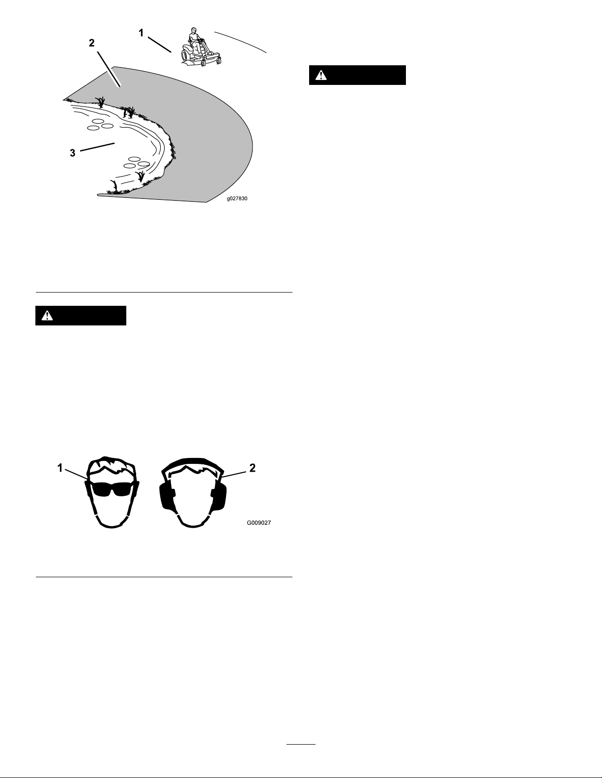
Figure9
1.Safezone—usethe
TimeCutterhere
2.Useawalk-behindmower
and/orhandtrimmernear
drop-offsandwater.
3.Water
CAUTION
Thismachineproducessoundlevelsin
excessof85dBAattheoperatorsearandcan
causehearinglossthroughextendedperiods
ofexposure.
Wearhearingprotectionwhenoperatingthis
machine.
Theuseofprotectiveequipmentforeyes,ears,feet,
andheadisrecommended.
g027830
Thesafety-interlocksystemisdesignedforthe
following:
•Topreventtheenginefromstartingunlessthe
tractionpedalisintheneutralposition.
•Toautomaticallyensurethattheparkingbrakeis
engagedandthePTOisoffwhenstarting.
•Tostoptheenginewheneverthetractionpedalis
notintheneutralpositionandyourisefromthe
seat.
•Toautomaticallyengagetheparkingbrakeand
disengagethePTO,whenyouriseoutoftheseat
withthetractionpedalintheneutralposition.
•Tostoptheenginewhenevertheparkingbrakeis
notengagedandyourisefromtheseat.
1.Wearsafetyglasses
g009027
Figure10
2.Wearhearingprotection
17
Page 18

TestingtheSafety-Interlock
16.Movetractionpedaltoreverse.
System
1.Whilesittingontheseat,movetheblade-control
switchtoOff.
2.TurntheignitionkeytotheStartposition.
Note:Thestartershouldcrank.
3.PushtheSmartParkswitchtotheOffposition.
Note:Thebrakeshoulddisengage,andthe
brakelightshouldturnoff.
4.Withbrakedisengagedandtractionpedalin
neutral,turntheignitionswitchtotheStart
position.
Note:Thebrakeshouldautomaticallyengage,
theengineshouldcrank,andthebrakelightwill
turnon.
5.EngagethePTObypullinguponthe
blade-controlswitch.
6.Ensurethetractionpedalisinneutralandturn
ignitionswitchtotheStartposition.
Note:ThePTOshoulddisengageandthe
engineshouldcrank.
7.Ensurethetractioncontrolpedalisintheneutral
positionandstarttheengine.
8.Raisefromtheseat.
Note:Thebladesshoulddisengage.
17.Engagethebladesbypullinguponthe
blade-controlswitch.
18.TurntheKeyChoiceswitchtoOnandrelease.
Note:Theoperatinginreverselightshould
illuminate.
19.Movethetractionpedaltoreverse.
Note:Thebladesshouldremainengaged.
20.PushthePTOswitchtotheoffposition.
Note:Thebladesshouldturnoffandthe
reversewarninglightshouldturnoff.
21.EngagetheparkingbrakebypushingSmartPark
switchtotheOnposition.
Note:Thebrakeshouldengageandthebrake
lightshouldbeon.
22.Pushandreleasethetractionpedalineitherthe
forwardorreversedirection.
Note:Thebrakeshoulddisengageandthe
brakelightshouldturnoff.
23.Raisefromtheseat,andpushthetractionpedal
toeithertheforwardorreversedirection.
Note:Theengineshouldkill.
Note:Theengineshouldremainrunning.
9.Returntotheseat,disengagetheparkingbrake
bypushingtheSmartParkswitchtotheOff
position.
Note:Theengineshouldremainrunning.
10.Raisefromtheseat.
Note:Thebrakeshouldautomaticallyengage
andtheengineshouldremainrunning.
11.Returntotheseat,engagethebladesbypulling
upontheblade-controlswitch.
12.Raisefromtheseat.
Note:Thebladesshoulddisengageandthe
engineshouldremainrunning.
13.Returntotheseat,andpulltheblade-control
switchup.
Note:Thebladesshouldengage.
14.Pushdownontheblade-controlswitch.
Note:Thebladesshoulddisengage.
StartingtheEngine
Important:Donotengagethestarterformore
than5secondsatatime.Engagingthestarter
motorformorethan5secondscandamagethe
startermotor.Iftheenginefailstostart,wait10
secondsbeforeoperatingtheenginestarteragain.
Sitdownontheseatandensuretheparkingbrakeis
set(Figure11).
15.Engagethebladesbypullinguponthe
blade-controlswitch.
18
Page 19
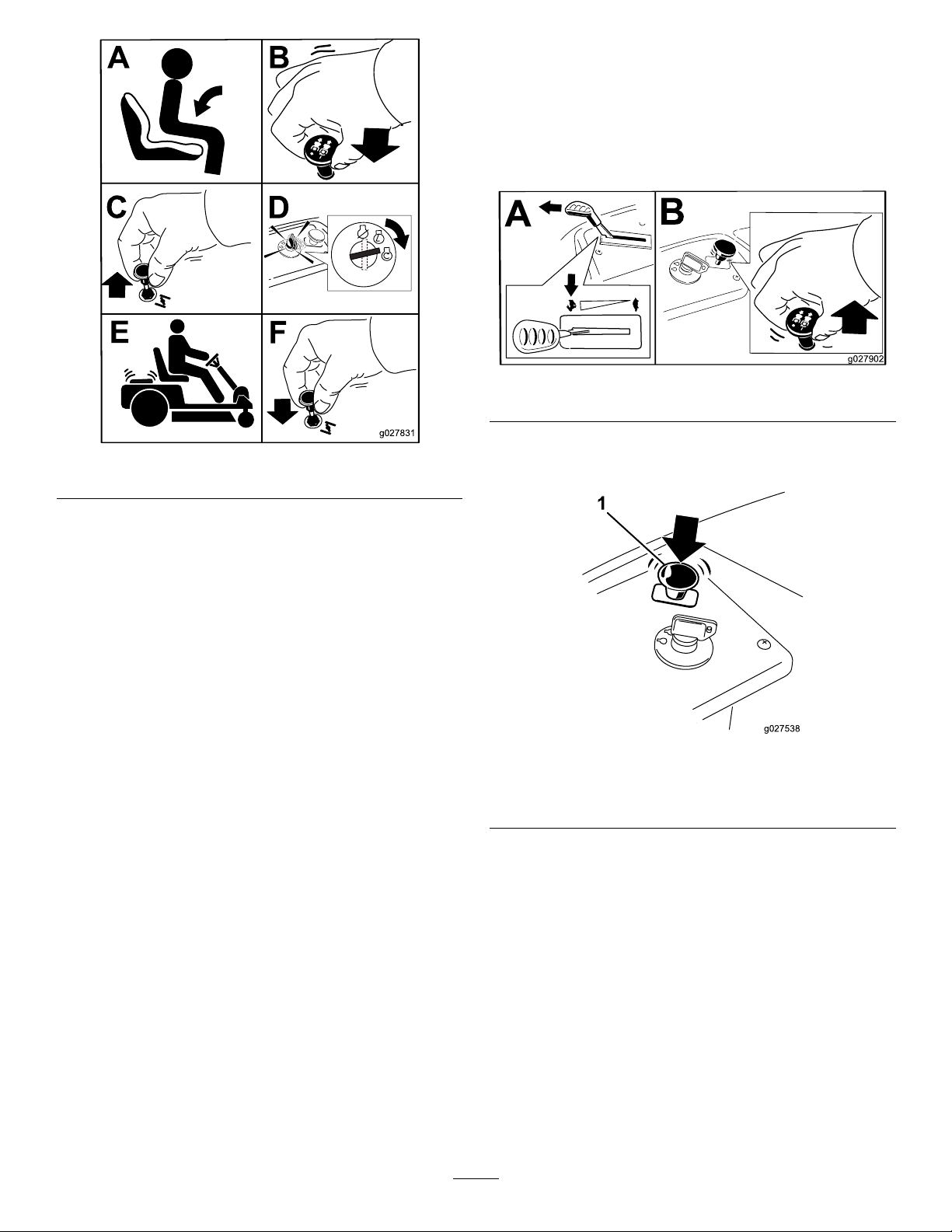
Figure11
EngagingtheBlades
Important:Donotengagethebladeswhen
parkedintallgrass.Beltorclutchdamagecan
occur.
Note:Alwaysengagethebladeswiththethrottlein
theFastposition.
g027902
Figure12
g027831
DisengagingtheBlades
OperatingtheParking
Brake(SmartPark
Theparkingbrakeisactivatedelectronically.
Engagetheparkingbrakebyoneofthefollowing
actions:
•PressingtheSmartPark
(Figure5).
•Theparkingbrakeengagesautomaticallywhen
theoperatorleavestheseatandthetraction
controlpedalisintheneutralposition.
•Theparkingbrakeautomaticallyengages5to6
secondsaftertheignitionswitchisturnedtothe
Offposition(ifnotalreadyengaged).
Disengagetheparkingbrakebyoneofthefollowing
actions:
•Tapthetraction-controlpedalforwardorreverse.
•PressingthebrakeswitchtotheOffposition
(Figure5).
™
™
switchtotheOnposition
)
g027538
Figure13
1.Powertake-off(PTO)switch
StoppingtheEngine
1.Disengagethebladesbypushingthe
blade-controlswitchtoOff(Figure13).
2.MovethethrottlelevertotheFastposition.
3.TurntheignitionkeytoOffandremovethekey.
OperatingtheBlades
Theblade-controlswitch,representedbyapower
take-off(PTO)symbol,engagesanddisengages
powertothemowerblades.Thisswitchcontrols
powertoanyattachmentsthatdrawpowerfromthe
engine,includingthemowerdeckandcuttingblades.
DrivingtheMachine
Thismachinehasthecharacteristicsofbothagarden
tractorandazero-turnmachine.Likeagarden
tractor,themachinehasafootpedalthatcontrolsthe
forwardandreversemotionalongwiththespeed,
19
Page 20
andithasasteeringwheelthatcontrolsthedirection
andtheturningradius.Likeazero-turnmachine,
thereardrivewheelsoperateindependentlyofeach
other,enablingyoutomakesharpturnsandtoturn
indifferentdirectionsquickly.Thesecharacteristics
vastlyimprovethemaneuverabilityofthemachine,
buttheymayalsorequireyoutopracticedrivingifyou
areunfamiliarwiththistypeofmachine.
StoppingtheMachine
Tostopthemachine,releasethetraction-control
pedal,disengagetheblade-controlswitch,ensurethe
throttleisinthefastpositions,settheparkingbrake
andturntheignitionkeytooff.
Note:Remembertoremovethekeyfromtheignition
switch.
WARNING
Themachinecanspinveryrapidly.The
operatormaylosecontrolofthemachine
andcausepersonalinjuryordamagetothe
machine.
•Usecautionwhenmakingturns.
•Slowthemachinedownbeforemaking
sharpturns.
Thethrottlecontrolregulatestheenginespeedas
measuredinrpm(revolutionsperminute).Placing
thethrottlecontrolintheFastpositioncanbebestfor
performance.Formostapplications,operatinginthe
full-throttlepositionisdesirable.
DrivingForwardorBackward
1.Movethethrottletothefastposition.
2.Releasetheparkingbrake.RefertoOperating
theParkingBrake(SmartPark
3.Placeyourfootontothetraction-controlpedal
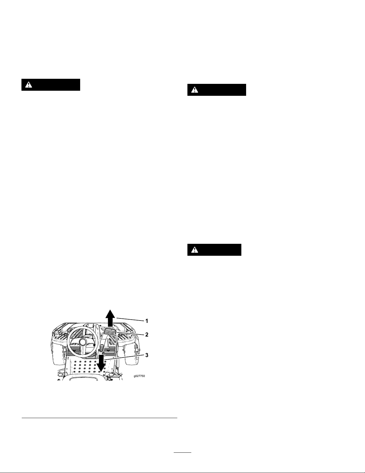
andslowlypressthetopofthepedaltogo
forward,orpressonthebottomofthepedalto
movebackward(Figure14).
™
)(page19).
WARNING
Childrenorbystandersmaybeinjuredifthey
moveorattempttooperatethemowerwhile
itisunattended.
Alwaysremovetheignitionkeyandsetthe
parkingbrakewhenleavingthemachine
unattended,evenifjustforafewminutes.
MowinginReverse
Themachinehasaninterlockfeaturethatprevents
themowerdeckfrommowingwhilethemachineis
travelinginreverse.Ifyoushiftintoreversewiththe
PTOengaged,thePTOwillstop.Ifyouneedtomow
whileinreversegear,youcantemporarilydeactivate
thisinterlock.
Note:Donotmowwhilebackingupunlessitis
absolutelynecessary.
DANGER
Achildorbystandercouldbebackedover
byaridingmowerwithbladesengagedand
causeseriouspersonalinjuryordeath.
Note:Thefartheryoumovethepedalineither
direction,thefasterthemachinewillmovein
thatdirection.
Figure14
1.Forward3.Backward
2.Traction-controlpedal
4.T oslowdown,releasethepressureonthe
traction-controlpedal.
•Donotmowinreverseunlessabsolutely
necessary.
•Alwayslookbackwardanddownbefore
backingup.
•UsetheKeyChoiceswitchonlyifyouare
certainnochildrenorotherbystanderswill
appearinthemowingarea.
•Alwaysremoveboththeignitionand
KeyChoicekeysandputtheminasafe
placeoutofthereachofchildrenor
unauthorizeduserswhenleavingtheunit
g027750
20
unattended.
Ifyouarecertainthatyoucansafelymoworoperate
anattachmentinreverse,completethefollowing
procedure:
1.InserttheKeyChoicekeyintotheKeyChoice
switch(Figure6).
Page 21
2.EngagethePTO.
3.TurntheKeyChoicekeyclockwiseuntilitstops
andreleaseit.
Note:Aredlightilluminatesontheconsoleto
serveasareminderthattheinterlockhasbeen
deactivated.
4.Performthemowing.
5.Whennishedmowing,removetheKeyChoice
key(Figure6).
Note:Onceyoudeactivatetheinterlock,it
staysinthismode—withyourmowerbladeor
PTOpoweredattachmentoperatingwhenever
youbackup—andtheconsolelightstayson
untilyoueitherdisengagethePTOorturnoff
theengine.
AdjustingtheHeight-of-Cut
Note:Thetransportpositionisthehighest
height-of-cutpositionorcuttingheight115mm
(4.5inches)asshowninFigure15.
Figure15
PositioningtheSteering Wheel
Thesteeringwheelhas3positionsforoperation
andone,full-upposition.Usethefull-uppositionfor
steppingonandoffthemachineandgettingoutof
theseat.Whenoperatingthemachine,positionthe
steeringwheelwhereyouhavethebestcontrolofthe
machineandaremostcomfortable.
1.Pressyourfootontothesteering-columnrelease
lever.
2.Positionthesteeringwheeltothedesired
position(Figure16).
g028025
21
Page 22
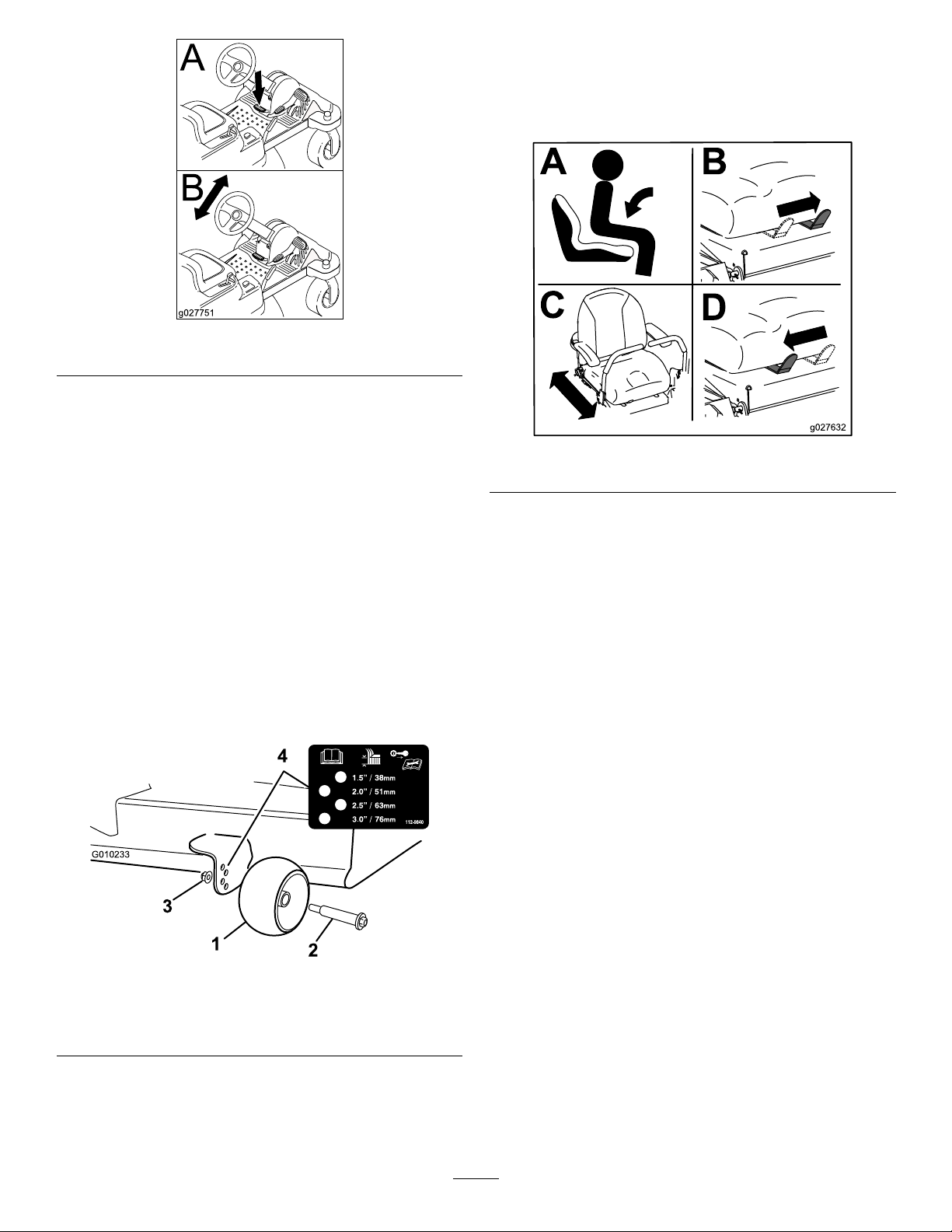
Figure16
PositioningtheSeat
Theseatcanmoveforwardandbackward.Position
theseatwhereyouhavethebestcontrolofthe
machineandaremostcomfortable.
g027751
AdjustingtheAnti-Scalp Rollers
Wheneveryouchangetheheight-of-cut,adjustthe
heightoftheanti-scalprollers.
Note:Adjusttheanti-scalprollerssotherollersdo
nottouchthegroundinnormal,atmowingareas.
1.Disengagetheblade-controlswitch(PTO),
ensuretheparkingbrakeisengaged.
2.Stoptheengine,removethekey,andwait
forallmovingpartstostopbeforeleavingthe
operatingposition.
3.Adjusttheanti-scalprollersasshowninFigure
17tomatchtheclosestheight-of-cutposition.
g027632
Figure18
PushingtheMachineby Hand
Important:Alwayspushthemachinebyhand.Do
nottowthemachine,becausedamagemayoccur.
Thismachinehasanelectric-brakemechanism,and
topushthemachine,theignitionkeyneedstobein
theRunposition.Thebatteryneedstobecharged
andfunctioningfortheelectricbraketobedisengage.
PushingtheMachine
1.Parkthemachineonalevelsurface,and
disengagetheblade-controlswitch.
2.Settheparkingbrake,stoptheengine,andwait
forallmovingpartstostopbeforeleavingthe
operatingposition.
Figure17
1.Anti-scalproller3.FlangeNut
2.Bolt4.Holespacing
3.Locatethebypassleversontheframeonboth
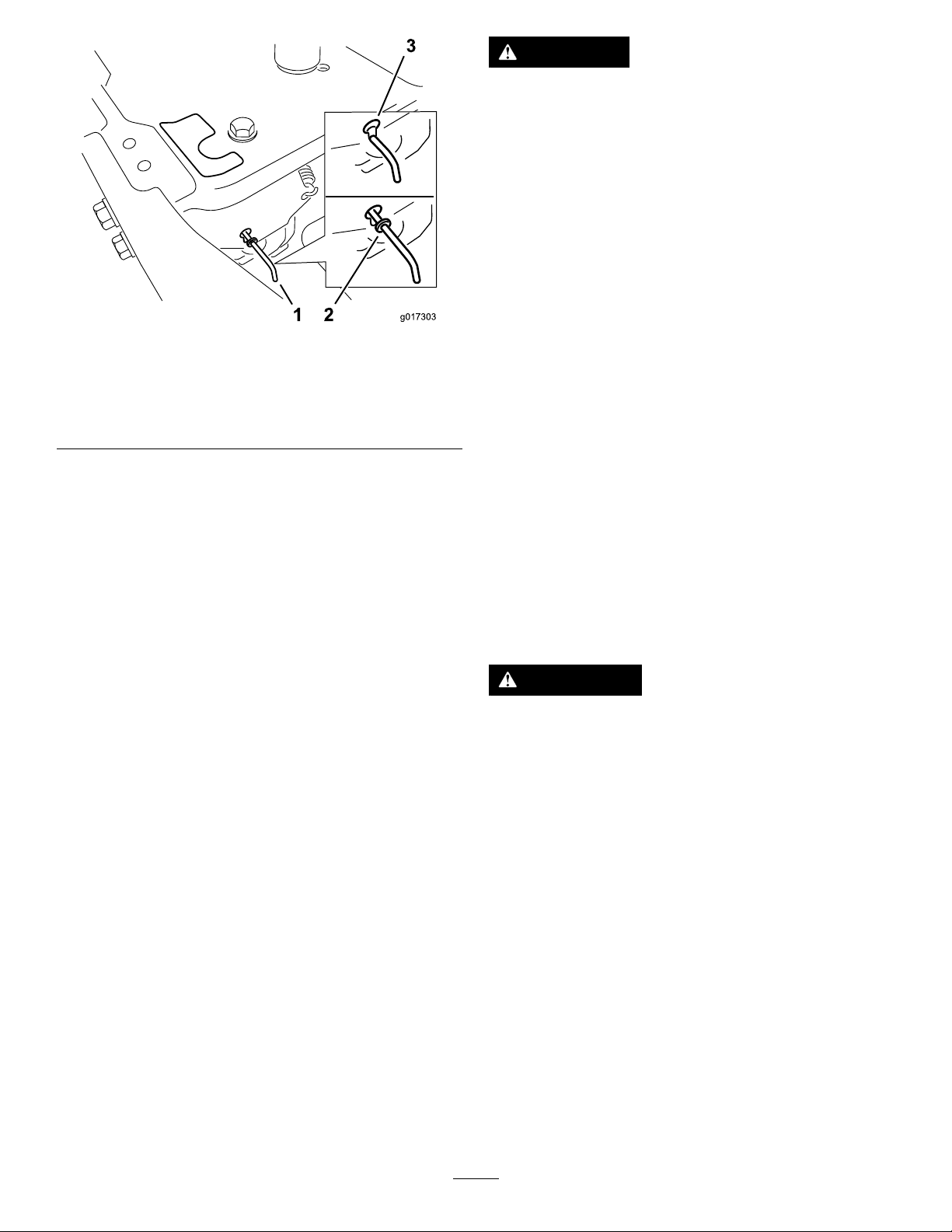
sidesoftheengine.
g010233
4.Movethebypassleversforwardthroughthekey
holeanddowntolocktheminplace(Figure19).
Note:Ensurethisisdoneforeachlever.
5.Turntheignitionkeyonanddisengagethe
parkingbrake.
Note:Donotstartthemachine.
Note:Themachineisnowabletobepushed
byhand.
22
Page 23
DANGER
Withoutthegrassdeector,dischargecover,
orcompletegrasscatcherassemblymounted
inplace,youandothersareexposedtoblade
contactandthrowndebris.Contactwith
rotatingmowerblade(s)andthrowndebris
willcauseinjuryordeath.
•Neverremovethegrassdeectorfrom
themowerbecausethegrassdeector
routesmaterialdowntowardtheturf.Ifthe
grassdeectoriseverdamaged,replaceit
immediately.
g017303
Figure19
1.Bypass-leverlocations
2.Leverpositionfor
operatingthemachine
6.Whennished,ensurethatthekeyhasbeen
returnedtotheStoppositiontoavoiddraining
thebatterycharge.
3.Leverpositionforpushing
themachine
Note:Ifthemachinefailstomove,theelectricbrake
maystillbeengaged.Ifnecessary,theelectricbrake
canbereleasedmanually;refertoReleasingthe
ElectricBrake(page37).
OperatingtheMachine
Movethebypassleversrearwardthroughthekeyhole
anddowntolocktheminplaceasshowninFigure19.
Note:Ensurethisisdoneforeachlever.
GrassDeector
Themowerhasahingedgrassdeectorthat
dispersesclippingstothesideanddowntowardthe
turf.
•Neverputyourhandsorfeetunderthe
mower.
•Nevertrytocleardischargeareaormower
bladesunlessyoumovetheblade-control
switchtoOffandrotatetheignitionkeyto
Off.Alsoremovethekeyandpullthewire
offthesparkplug(s).
TransportingtheMachine
Useaheavy-dutytrailerortrucktotransportthe
machine.Ensurethatthetrailerortruckhasall
necessarybrakes,lighting,andmarkingasrequired
bylaw.Pleasecarefullyreadallthesafetyinstructions.
Knowingthisinformationcouldhelpyou,yourfamily,
pets,orbystandersavoidinjury.
WARNING
Drivingonthestreetorroadwaywithoutturn
signals,lights,reectivemarkings,oraslow
movingvehicleemblemisdangerousandcan
leadtoaccidentscausingpersonalinjury.
Donotdrivemachineonapublicstreetor
roadway.
Totransportthemachine:
1.Ifusingatrailer,connectittothetowingvehicle
andconnectthesafetychains.
2.Ifapplicable,connectthetrailerbrakes.
3.Loadthemachineontothetrailerortruck.
4.Stoptheengine,removethekey,setthebrake,
andclosethefuelvalve.
5.Tiedownthemachinenearthefrontcaster
wheelsandtherearbumper(Figure20).
Note:Avoidthesteeringcomponentswhen
tyingdownthemachineatthefrontcaster
wheels.
23
Page 24
WARNING
Loadingamachineontoatrailerortruck
increasesthepossibilityoftip-overandcould
causeseriousinjuryordeath.
•Useextremecautionwhenoperatinga
machineonaramp.
Figure20
LoadingtheMachine
Useextremecautionwhenloadingorunloading
machinesontoatraileroratruck.Useafull-width
rampthatiswiderthanthemachineforthisprocedure.
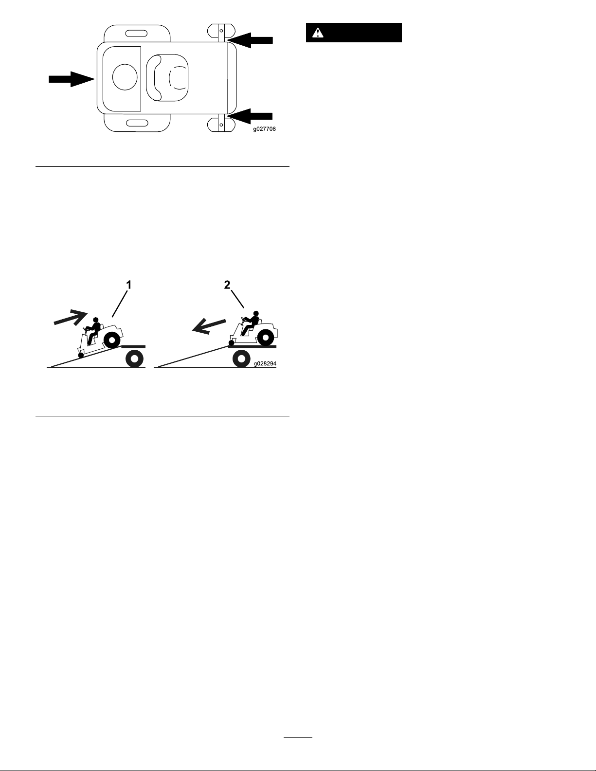
Backuprampsanddriveforwarddownramps(Figure
21).
Figure21
1.Backupramps
2.Driveforwarddownramps
g027708
•Useonlyafull-widthramp;donotuse
individualrampsforeachsideofthe
machine.
•Donotexceeda15-degreeanglebetween
therampandthegroundorbetweenthe
rampandthetrailerortruck.
•Ensurethelengthoframpisatleastfour
times(4X)aslongastheheightofthe
trailerortruckbedtotheground.Thiswill
ensurethatrampangledoesnotexceed15
degreesonatground.
•Backuprampsanddriveforwarddown
ramps.
•Avoidsuddenaccelerationordeceleration
whiledrivingthemachineonarampas
thiscouldcausealossofcontrolora
tip-oversituation.
g028294
Important:Donotusenarrowindividualramps
foreachsideofthemachine.
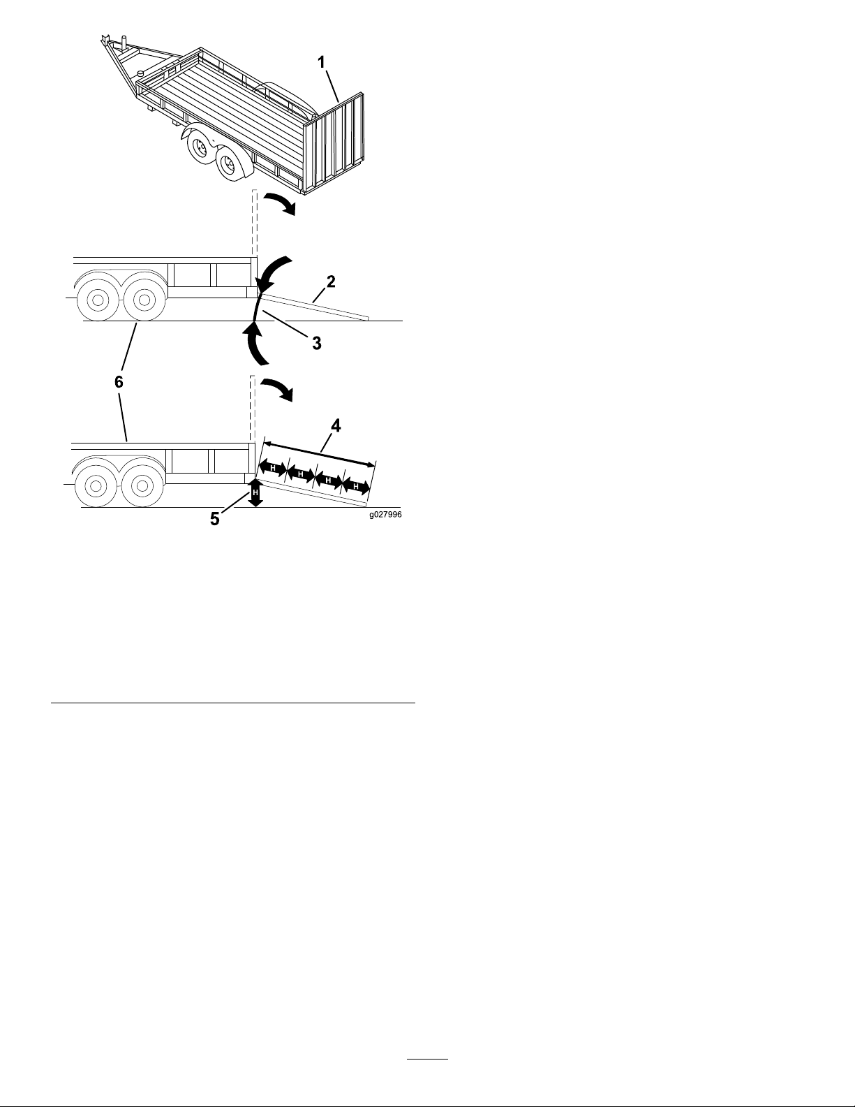
Ensuretherampislongenoughsothattheanglewith
thegrounddoesnotexceed15degrees(Figure22).
Onatground,thisrequiresaramptobeatleastfour
times(4X)aslongastheheightofthetrailerortruck
bedtotheground.Asteeperanglemaycausemower
componentstogetcaughtastheunitmovesfromthe
ramptothetrailerortruck.Steeperanglesmayalso
causethemachinetotiporlosecontrol.Ifloadingon
ornearaslope,positionthetrailerortrucksothatitis
onthedownsideoftheslopeandtherampextends
uptheslope.Thiswillminimizetherampangle.
24
Page 25
OperatingTips
UsingtheFastThrottleSetting
Forbestmowingandmaximumaircirculation,operate
theengineattheFastthrottleposition.Airisrequired
tothoroughlycutgrassclippings,sodonotsetthe
height-of-cutsolowastototallysurroundthemower
byuncutgrass.Alwaystrytohaveonesideofthe
mowerfreefromuncutgrass,whichallowsairtobe
drawnintothemower.
CuttingaLawnfortheFirstTime
Cutgrassslightlylongerthannormaltoensurethat
thecuttingheightofthemowerdoesnotscalpany
unevenground.However,thecuttingheightusedin
thepastisgenerallythebestonetouse.Whencutting
grasslongerthansixinchestall,youmaywanttocut
thelawntwicetoensureanacceptablequalityofcut.
Cutting1/3oftheGrassBlade
Itisbesttocutonlyabout1/3ofthegrassblade.
Cuttingmorethanthatisnotrecommendedunless
grassissparse,oritislatefallwhengrassgrows
moreslowly.
1.Full-widthrampinstowed
position
2.Sideviewoffull-width
rampinloadingposition
3.Notgreaterthan
15degrees
Figure22
4.Rampisatleastfourtimes
(4X)aslongastheheight
ofthetrailerortruckbed
totheground
5.H=heightofthetraileror
truckbedtotheground
6.Trailer
g027996
MowingDirection
Alternatethemowingdirectiontokeepthegrass
standingstraight.Thisalsohelpsdisperseclippings
whichenhancesdecompositionandfertilization.
MowingatCorrectIntervals
Normally,mowevery4days.But,remember,grass
growsatdifferentratesatdifferenttimes.Soto
maintainthesamecuttingheight,whichisagood
practice,andmowmoreofteninearlyspring.Asthe
grassgrowthrateslowsinmidsummer,mowless
frequently.Ifyoucannotmowforanextendedperiod,
rstmowatahighcuttingheight,thenmowagain2
dayslateratalowerheightsetting.
AvoidingCuttingTooLow
Ifthecuttingwidthofthemoweriswiderthanthe
moweryoupreviouslyused,raisethecuttingheightto
ensurethatuneventurfisnotcuttooshort.
CuttingLongGrass
Ifthegrassiseverallowedtogrowslightlylongerthan
normal,orifitcontainsahighdegreeofmoisture,
raisethecuttingheighthigherthanusualandcutthe
grassatthissetting.Thencutthegrassagainusing
thelower,normalsetting.
25
Page 26

Stopping
Ifyoumuststopthemachine'sforwardmotionwhile
mowing,aclumpofgrassclippingsmaydroponto
yourlawn.Toavoidthis,moveontoapreviouslycut
areawiththebladesengagedoryoucandisengage
themowerdeckwhilemovingforward.
KeepingtheUndersideofthe
MowerClean
Cleanclippingsanddirtfromtheundersideofthe
moweraftereachuse.Ifgrassanddirtbuildupinside
themower,cuttingqualitywilleventuallybecome
unsatisfactory.
MaintainingtheBlade(s)
Maintainasharpbladethroughoutthecuttingseason
becauseasharpbladecutscleanlywithouttearingor
shreddingthegrassblades.Tearingandshredding
turnsgrassbrownattheedges,whichslowsgrowth
andincreasesthechanceofdisease.Checkthe
mowerbladesaftereachuseforsharpness,and
foranywearordamage.Filedownanynicksand
sharpenthebladesasnecessary.Ifabladeis
damagedorworn,replaceitimmediatelywitha
genuineT ororeplacementblade.
26
Page 27

Maintenance
Note:Determinetheleftandrightsidesofthemachinefromthenormaloperatingposition.
RecommendedMaintenanceSchedule(s)
MaintenanceService
Interval
Aftertherst5hours
Aftertherst50hours
Beforeeachuseordaily
Aftereachuse
Every25hours
Every100hours
Every200hours
MaintenanceProcedure
•Changetheengineoil.
•Changetheoilandltersforthehydraulicsystem,andbleedthesystem.
•Checktheengine-oillevel.
•Cleantheairintakescreen.
•Checkthecuttingblades.
•Inspectthegrassdeectorfordamage.
•Checkandcleanthefrontofthemower.
•Cleanthemowerhousing.
•Greaseallthelubricationpoints.
•Cleantheair-cleanerfoamelement(moreoftenindusty ,dirtyconditions).
•Checktirepressure.
•Checktheoillevelintheexpansiontank.
•Checkthebeltsforwear/cracks.
•Replacetheair-cleanerfoamelement(moreoftenindusty,dirtyconditions).
•Servicetheair-cleanerpaperelement(moreoftenindusty,dirtyconditions).
•Changetheengineoil(moreoftenindusty,dirtyconditions).
•Changetheoillter(moreoftenindusty,dirtyconditions).
•Checkthesparkplug(s).
•Checkthein-linefuellter.
•Replacetheair-cleanerpaperelement(moreoftenindusty,dirtyconditions).
•Replacethesparkplug(s).
•Replacethein-linefuellter.
Every400hours
Beforestorage
•Changetheoilandltersforthehydraulicsystem,andbleedthesystem.
•Chargethebatteryanddisconnectbatterycables.
•Performallmaintenanceprocedureslistedabovebeforestorage.
•Paintanychippedsurfaces.
CAUTION
Ifyouleavethekeyintheignitionswitch,someonecouldaccidentlystarttheengineand
seriouslyinjureyouorotherbystanders.
Removethekeyfromtheignitionanddisconnectthewirefromthesparkplugbeforeyoudo
anymaintenance.Setthewireasidesothatitdoesnotaccidentallycontactthesparkplug.
27
Page 28
Pre-Maintenance
Lubrication
Procedures
GreasingtheBearings
RaisingtheSeat
Makesurethattheparkingbrakeisengaged,andlift
theseatforward.
Thefollowingcomponentscanbeaccessedbyraising
theseat:
•Serialplate
•Servicedecal
•Seat-adjustmentbolts
•Fuellter
•Batteryandbatterycables
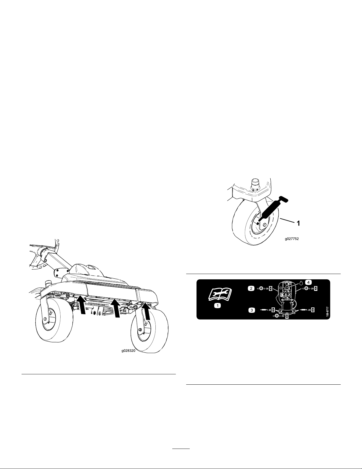
RaisingtheFrontofthe Machine
Ifthefrontofthemachineneedstoberaised,usethe
veryfrontedgeasshowinFigure23.
Important:Topreventdamagetothesteering
mechanism,ensuretheveryfrontedgeofthe
machineisusedforjackingpoints.
ServiceInterval:Every25hours—Greaseallthe
lubricationpoints.
GreaseType:No.2general-purpose,lithium-based
grease
1.Parkthemachineonalevelsurface,and
disengagetheblade-controlswitch.
2.Ensuretheparkingbrakeisengaged,stopthe
engine,removethekey,andwaitforallmoving
partstostopbeforeleavingtheoperating
position.
3.Cleanthegreasettings(Figure24andFigure
25)witharag.
Note:Makesuretoscrapeanypaintoffofthe
frontofthetting(s).
Figure23
g027752
Figure24
1.Frontcastertire
decal106-8717
Figure25
Locatedontheseat-panunderside
1.Readtheinstructions
g028320
beforeservicingor
performingmaintenance
2.Checkthetirepressure
every25operatinghours
4.Connectagreaseguntoeachtting(Figure24
andFigure25).
5.Pumpgreaseintothettingsuntilgreasebegins
tooozeoutofthebearings.
3.Greaseevery25operating
hours
4.Engine
28
Page 29
EngineMaintenance
ServicingtheAirCleaner
Note:Servicetheaircleanermorefrequently(every
fewhours)ifoperatingconditionsareextremelydusty
orsandy.
RemovingtheElements
1.Parkthemachineonalevelsurfaceand
disengagetheblade-controlswitch(PTO).
2.Engagetheparkingbrake,stoptheengine,
removethekey,andwaitforallmovingpartsto
stopbeforeleavingtheoperatingposition.
3.Cleanaroundtheair-cleanercovertoprevent
dirtfromgettingintotheengineandcausing
damage.
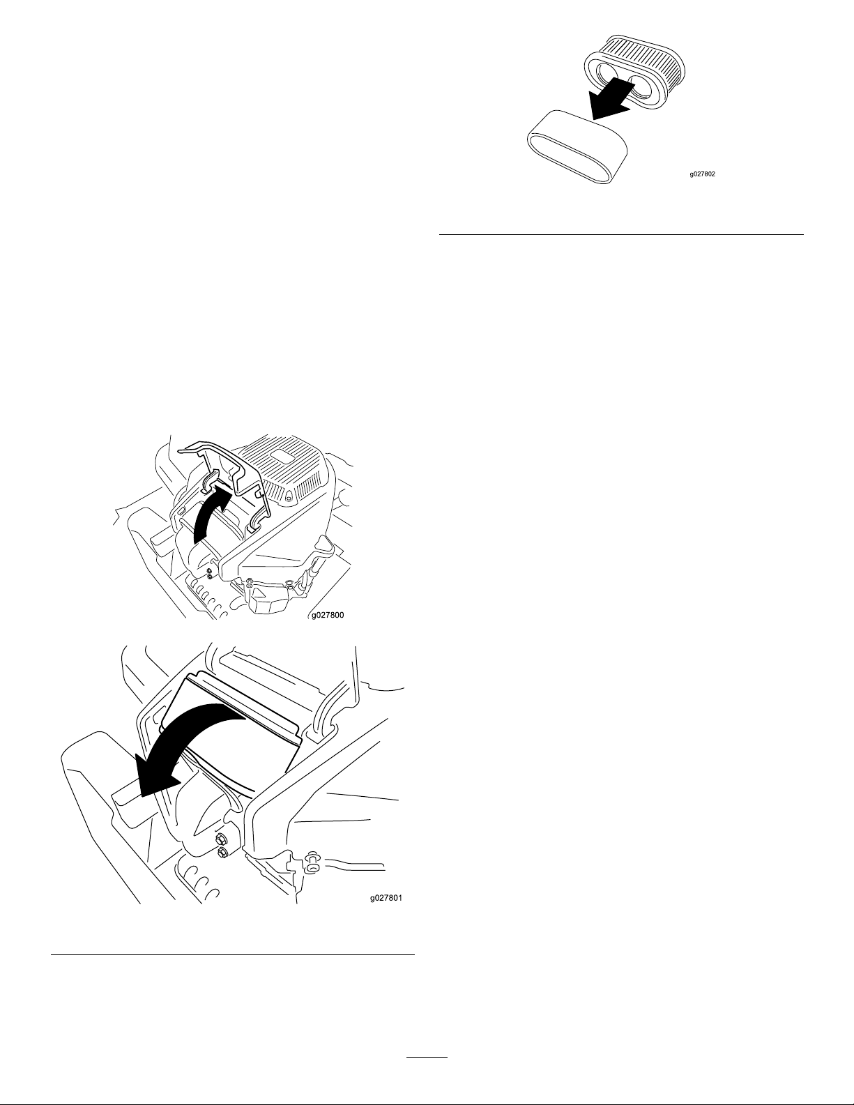
4.Liftthecoverandrotatetheair-cleanerassembly
outoftheengine(Figure26).
g027802
Figure27
ServicingtheFoamElement
ServiceInterval:Every25hours/Monthly(whichever
comesrst)—Cleantheair-cleaner
foamelement(moreoftenindusty,
dirtyconditions).
Every100hours/Y early(whichevercomes
rst)—Replacetheair-cleanerfoamelement
(moreoftenindusty,dirtyconditions).
Washthefoamelementwithwaterandreplacethe
foamelementifitisdamaged.
Figure26
ServicingthePaperElement
ServiceInterval:Every100hours/Yearly(whichever
comesrst)—Servicetheair-cleaner
paperelement(moreoftenindusty,
dirtyconditions).
Every200hours/Every2years(whichever
g027800
g027801
comesrst)—Replacetheair-cleanerpaper
element(moreoftenindusty,dirtyconditions).
1.Lightlytaptheelementonaatsurfaceto
removedustanddirt.
2.Inspecttheelementfortears,anoilylm,and
damagetotheseal.
Important:Donotcleanthepaperelement
withpressurizedairorliquids,suchas
solvent,gas,orkerosene.Replacethepaper
elementifitisdamagedorcannotbecleaned
thoroughly.
5.Removethefoamelementfromthepaper
element(Figure27).
29
Page 30
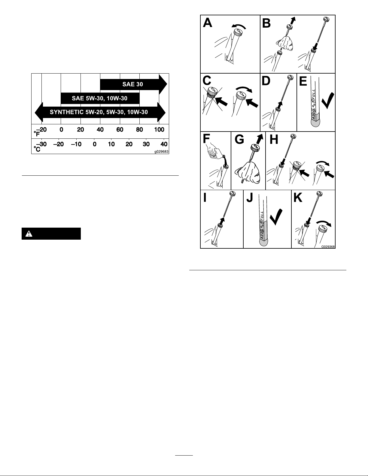
ServicingtheEngineOil
OilType:Detergentoil(APIserviceSF,SG,SH,SJ,
orSL)
CrankcaseCapacity:2.4L(2.5USqt)
Viscosity:Seethetablebelow.
Figure28
CheckingtheEngine-OilLevel
g029683
ServiceInterval:Beforeeachuseordaily
Note:Checktheoilwhentheengineiscold.
WARNING
Contactwithhotsurfacesmaycausepersonal
injury.
Keephands,feet,face,clothing,andother
bodypartsawaythemuferandotherhot
surfaces.
Important:Donotoverllthecrankcasewithoil,
becausedamagetotheenginemayresult.Donot
runenginewithoilbelowtheLowmark,because
theenginemaybedamaged.
1.Parkthemachineonalevelsurface,disengage
theblade-controlswitch,stoptheengine,
engageparkingbrake,andremovethekey.
2.Makesuretheengineisstopped,level,andis
cool,sotheoilhashadtimetodrainintothe
sump.
3.T okeepdirt,grassclippings,etc.,outofthe
engine,cleantheareaaroundtheoil-llcapand
dipstickbeforeremovingit(Figure29).
4.Stoptheengine,removethekey,andwait
forallmovingpartstostopbeforeleavingthe
operatingposition.
g029368
Figure29
ChangingtheEngineOilandOil
Filter
ServiceInterval:Aftertherst5hours/Afterthe
rstmonth(whichevercomes
rst)—Changetheengineoil.
Every100hours/Y early(whichevercomes
rst)—Changetheengineoil(moreoftenin
dusty,dirtyconditions).
Every100hours/Y early(whichevercomes
rst)—Changetheoillter(moreoftenindusty,
dirtyconditions).
Note:Changetheengine-oilltermorefrequently
whenoperatingconditionsareextremelydustyor
sandy.
Note:Disposeoftheusedoilatarecyclingcenter.
1.Parkthemachineonalevelsurfacetoensure
theoildrainscompletely.
30
Page 31
2.DisengagethePTOandensuretheparking
brakeisengaged.
3.Stoptheengine,removethekey,andwait
forallmovingpartstostopbeforeleavingthe
operatingposition.
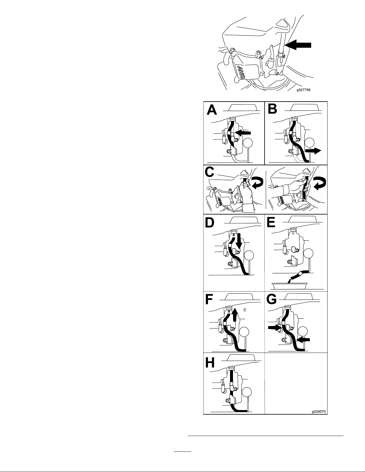
4.Draintheengineoil.
g027799
g029570
Figure30
31
Page 32
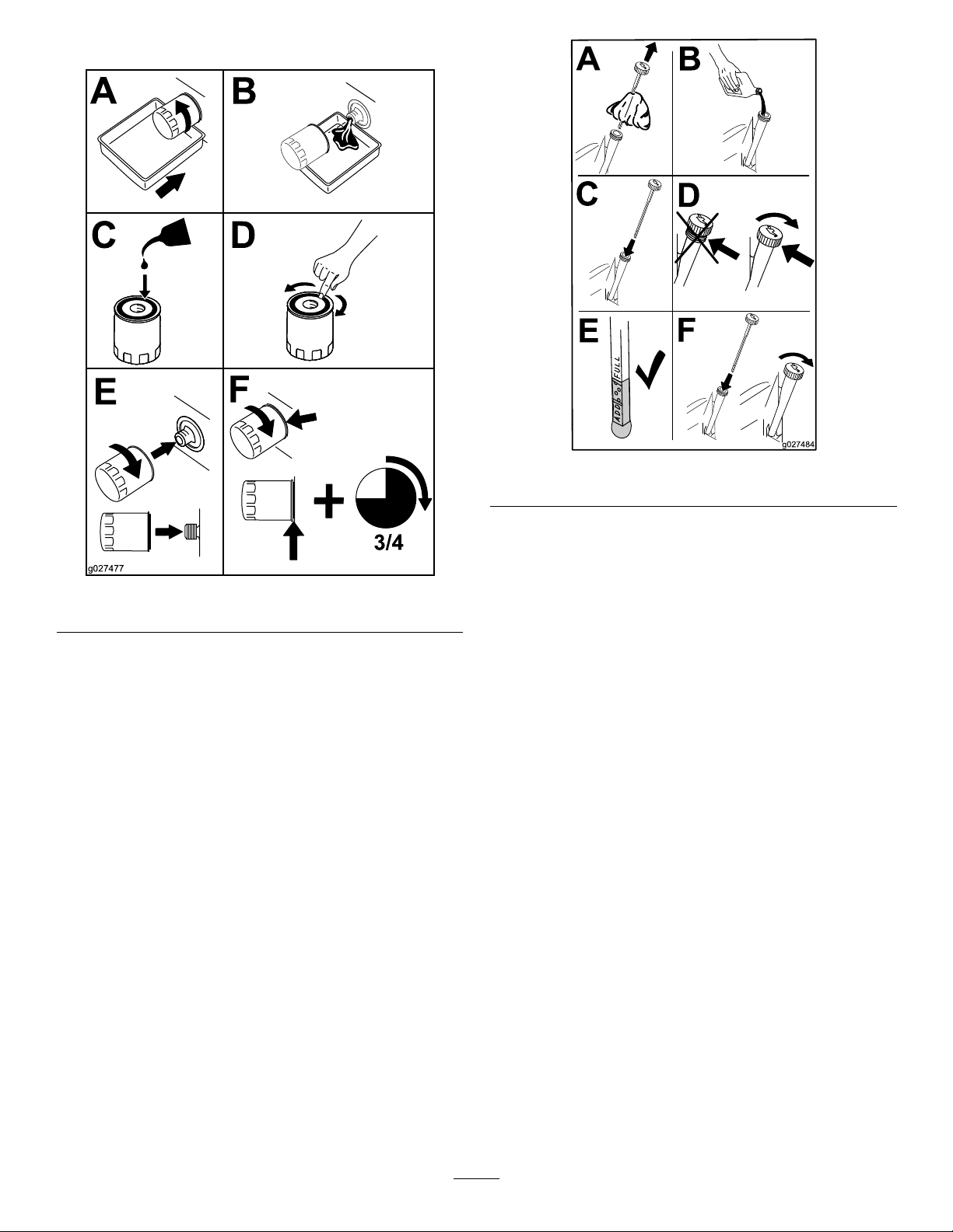
5.Changetheengineoillter(Figure31).
g027484
Figure32
Figure31
Note:Ensurethattheoil-ltergaskettouches
theengineandthenanextra3/4turnis
completed.
6.Slowlypourapproximately80%ofthespecied
oilintothellertubeandslowlyaddthe
additionaloiltobringittotheFullmark(Figure
32).
ServicingtheSparkPlug
g027477
ServiceInterval:Every100hours/Yearly(whichever
comesrst)—Checkthespark
plug(s).
Every200hours/Every2years(whichever
comesrst)—Replacethesparkplug(s).
Makesuretheairgapbetweenthecenterandside
electrodesiscorrectbeforeinstallingthesparkplug.
Useaspark-plugwrenchforremovingandinstalling
thesparkplug(s)andagappingtool/feelergaugeto
checkandadjusttheairgap.Installanewspark
plug(s)ifnecessary.
Type:ChampionRN9YCorNGKBPR6ES
Airgap:0.76mm(0.03inch)
RemovingtheSparkPlug
1.DisengagethePTOandensuretheparking
brakeisengaged.
2.Stoptheengine,removethekey,andwait
forallmovingpartstostopbeforeleavingthe
operatingposition.
32
Page 33
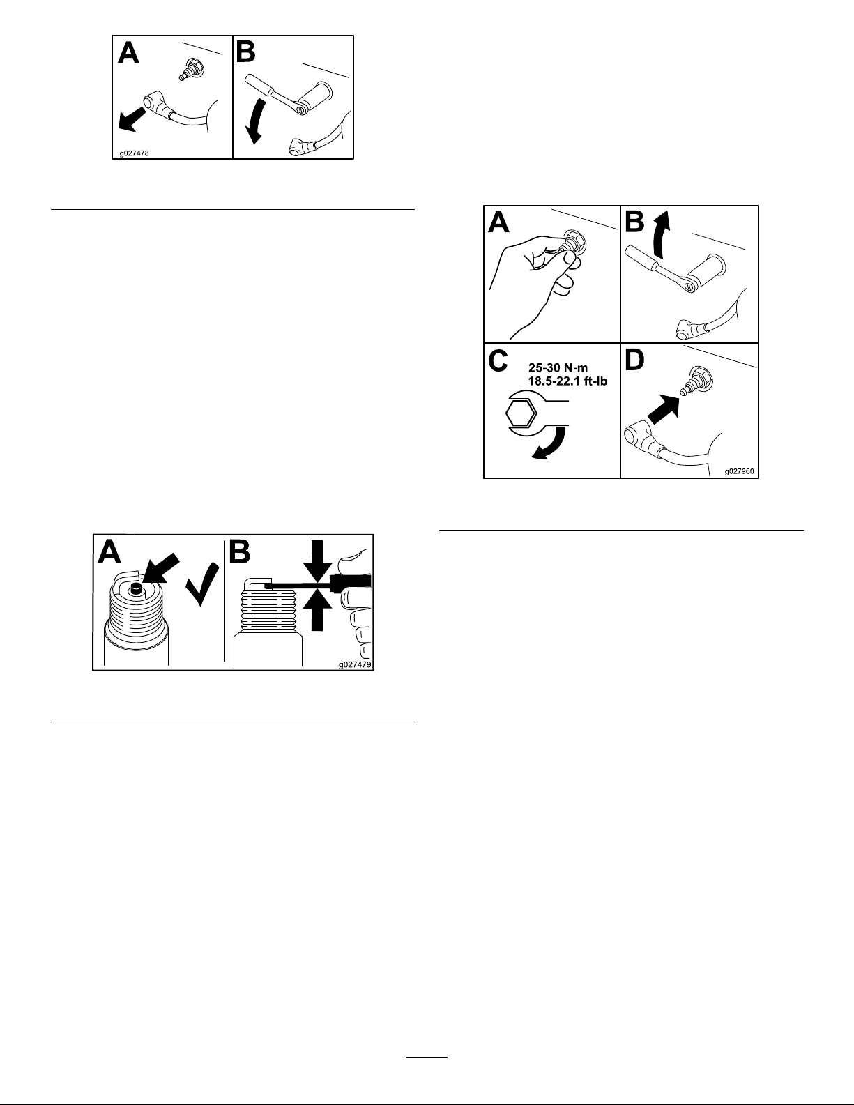
Figure33
Note:Duetothedeeprecessaroundthespark
plug,blowingoutthecavitywithcompressedair
isusuallythemosteffectivemethodforcleaning.
Thesparkplugismostaccessiblewhenthe
blowerhousingisremovedforcleaning.
CheckingtheSparkPlug
Important:Donotcleanthesparkplug(s).
Alwaysreplacethesparkplug(s)whenithas:a
blackcoating,wornelectrodes,anoilylm,or
cracks.
InstallingtheSparkPlug
Note:Ifatorquewrenchisnotavailablewhen
installingasparkplug,installausedsparkplugan
1/8–1/4turnpastngertightandinstallanewspark
pluga1/2turnpastngertight.Ensurethesparkplug
istightenedwithatorquewrenchassoonaspossible.
g027478
Tightenthesparkplug(s)to25–30N-m(18.5–22.1
ft-lb).
Ifyouseelightbrownorgrayontheinsulator,the
engineisoperatingproperly.Ablackcoatingonthe
insulatorusuallymeanstheaircleanerisdirty .
Setthegapto0.76mm(0.030inch).
Figure34
g027960
Figure35
CleaningtheCooling System
Cleantheairintakescreenfromgrassanddebris
beforeeachuse.
g027479
1.Disengagetheblade-controlswitchandapply
theparkingbrake.
2.Stoptheengine,removethekey,andwait
forallmovingpartstostopbeforeleavingthe
operatingposition.
3.Removetheengineshroud.
4.Cleandebrisandgrassfromtheparts.
5.Installtheengineshroud.
33
Page 34
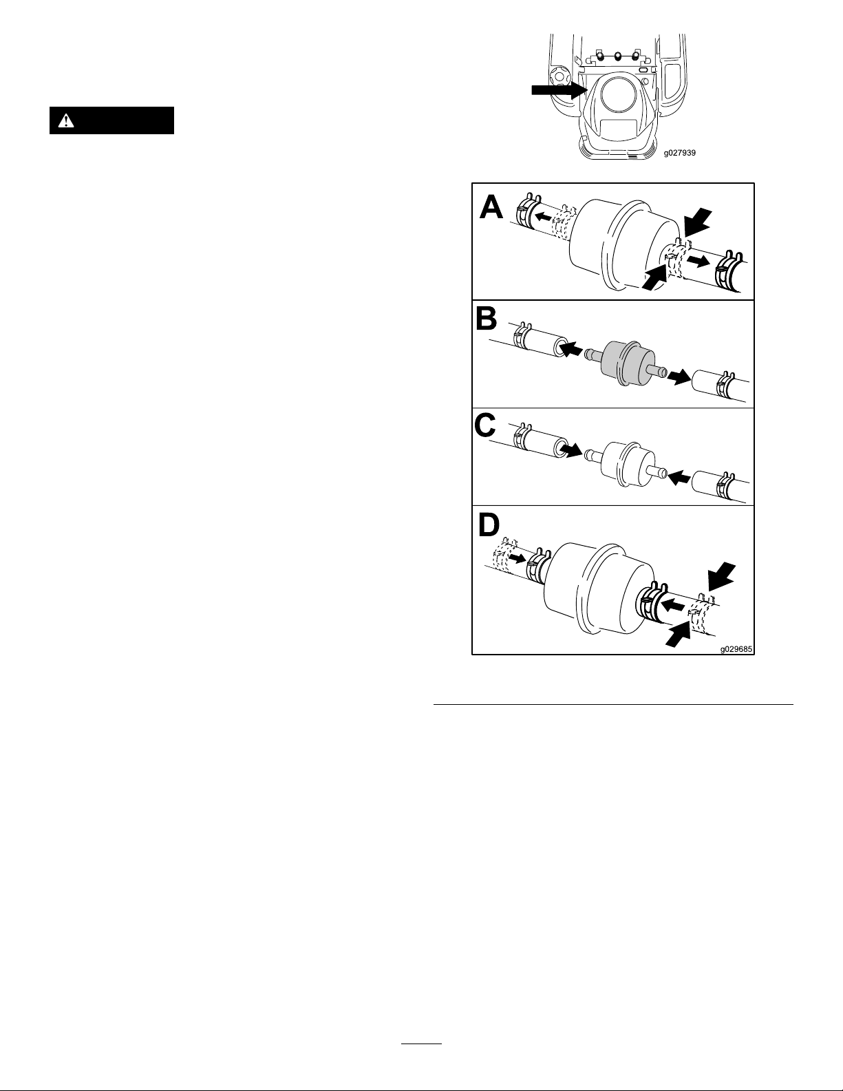
FuelSystem
Maintenance
DANGER
Incertainconditions,gasolineisextremely
ammableandhighlyexplosive.Areor
explosionfromgasolinecanburnyouand
othersandcandamageproperty.
•Performanyfuelrelatedmaintenance
whentheengineiscold.Dothisoutdoors
inanopenarea.Wipeupanygasolinethat
spills.
•Neversmokewhendraininggasoline,and
stayawayfromanopenameorwherea
sparkmayignitethegasolinefumes.
ReplacingtheIn-LineFuel Filter
g027939
ServiceInterval:Every100hours/Yearly(whichever
comesrst)—Checkthein-linefuel
lter.
Every200hours/Every2years(whichever
comesrst)—Replacethein-linefuellter.
Neverinstalladirtylterifitisremovedfromthefuel
line.
1.Parkthemachineonalevelsurfaceand
disengagetheblade-controlswitch.
2.Ensurethebrakeisengaged,stoptheengine,
removethekey,andwaitforallmovingpartsto
stopbeforeleavingtheoperatingposition.
g029685
Figure36
34
Page 35
ElectricalSystem
Maintenance
WARNING
CALIFORNIA
Proposition65Warning
Batteryposts,terminals,andrelated
accessoriescontainleadandlead
compounds,chemicalsknownto
theStateofCaliforniatocause
cancerandreproductiveharm.Wash
handsafterhandling.
ChargingtheBattery
RemovingtheBattery
WARNING
WARNING
Incorrectbatterycableroutingcould
damagethemachineandcablescausing
sparks.Sparkscancausethebattery
gassestoexplode,resultinginpersonal
injury.
•Alwaysdisconnectthenegative
(black)batterycablebefore
disconnectingthepositive(red)
cable.
•Alwaysconnectthepositive(red)
batterycablebeforeconnectingthe
negative(black)cable.
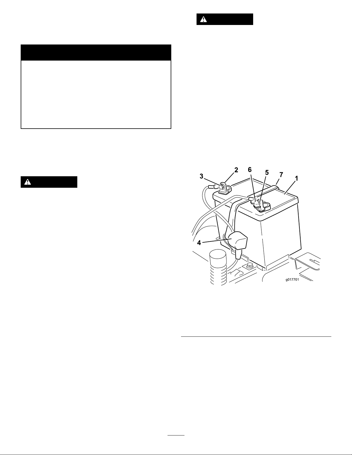
5.Slidetherubbercoverupthepositive(red)
cable.Disconnectthepositive(red)cablefrom
thebatterypost(Figure37).Retainallfasteners.
6.Removethebatteryhold-down(Figure37)and
liftthebatteryfromthebatterytray.
Batteryterminalsormetaltoolscouldshort
againstmetalmachinecomponentscausing
sparks.Sparkscancausethebatterygasses
toexplode,resultinginpersonalinjury.
•Whenremovingorinstallingthebattery,
donotallowthebatteryterminalstotouch
anymetalpartsofthemachine.
•Donotallowmetaltoolstoshortbetween
thebatteryterminalsandmetalpartsofthe
machine.
1.Parkthemachineonalevelsurfaceand
disengagetheblade-controlswitch.
2.Ensuretheparkingbrakeisengaged,stopthe
engine,removethekey,andwaitforallmoving
partstostopbeforeleavingtheoperating
position.
3.Raisetheseattoaccessthebattery.
4.Disconnectthenegative(black)groundcable
fromthebatterypost(Figure37).Retainall
fasteners.
g017701
Figure37
1.Battery5.Negativebatterypost
2.Positivebatterypost6.Wingnut,washer ,andbolt
3.Bolt,washer,andnut7.Batteryhold-down
4.Terminalboot
ChargingtheBattery
ServiceInterval:Beforestorage—Chargethebattery
anddisconnectbatterycables.
1.Removethebatteryfromthechassis;referto
RemovingtheBattery.
2.Chargethebatteryforaminimumof1hourat6
to10amps.Donotoverchargethebattery.
3.Whenthebatteryisfullycharged,unplug
thechargerfromtheelectricaloutlet,then
35
Page 36
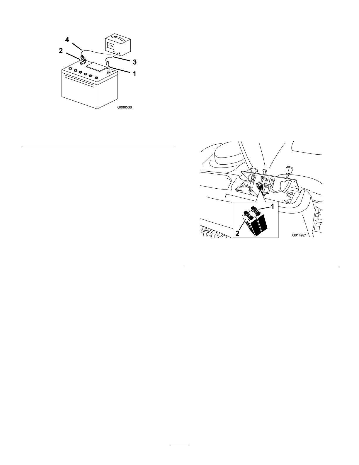
disconnectthechargerleadsfromthebattery
posts(Figure38).
ServicingtheFuses
Theelectricalsystemisprotectedbyfuses.Itrequires
nomaintenance;however,ifafuseblows,checkthe
component/circuitforamalfunctionorshort.
Fuse:
•MainF1-30amp,blade-type
•ChargeCircuitF2-25amp,blade-type
1.Removethescrewssecuringthecontrolpanel
tothemachine.Retainallfasteners
Figure38
1.Positivebatterypost
2.Negativebatterypost
3.Red(+)chargerlead
4.Black(-)chargerlead
InstallingtheBattery
1.Positionthebatteryinthetray(Figure37).
2.Installthepositive(red)batterycabletothe
positive(+)batteryterminalusingthefasteners
removedpreviously.
3.Installthenegativebatterycabletothenegative
(-)batteryterminalusingthefastenersremoved
previously.
4.Slidetheredterminalbootontothepositive
(red)batterypost.
5.Securethebatterywiththehold-down(Figure
37).
6.Lowertheseat.
g000538
2.Liftthecontrolpaneuptoaccessthemainwiring
harnessandfuseblock(Figure39).
3.T oreplaceafuse,pulloutonthefusetoremove
it(Figure39).
g014921
Figure39
1.Main-30amp
2.Chargecircuit-25amp
4.Returnthecontrolpaneltoitsoriginalposition.
Usethescrewsremovedpreviouslytosecure
thepaneltothemachine.
36
Page 37
DriveSystem
Maintenance
CheckingtheTirePressure
ServiceInterval:Every25hours—Checktire
pressure.
Maintaintheairpressureinthefrontandreartiresas
specied.Uneventirepressurecancauseuneven
cut.Checkthepressureatthevalvestem(Figure40).
Checkthetireswhentheyarecoldtogetthemost
accuratepressurereading.
Refertothemaximumpressuresuggestedbythetire
manufactureronthesidewallofthecasterwheeltires.
Inatethereardrivewheeltiresto90kPa(13psi).
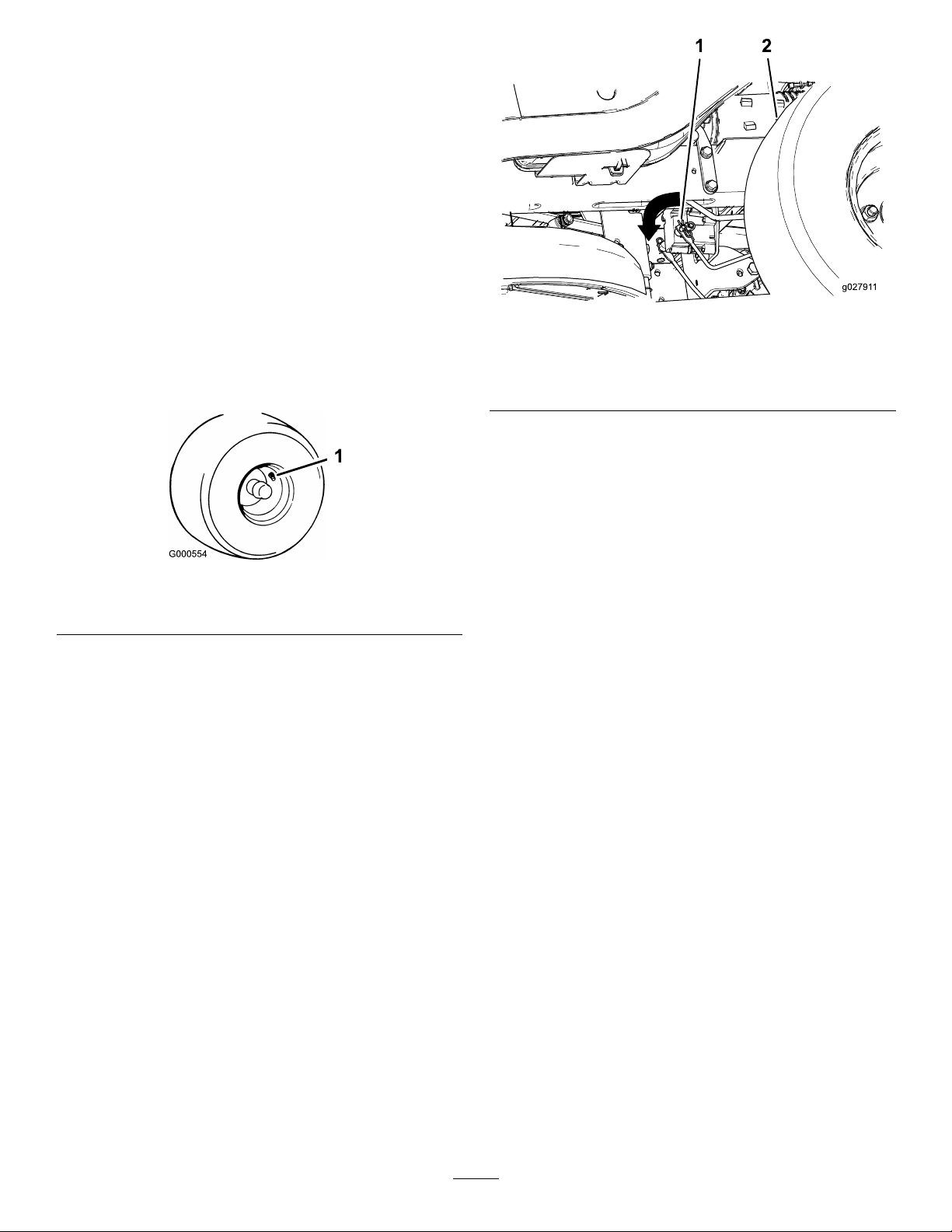
g027911
Figure41
1.Rotatebrake-linkarmforwardontheelectric-brake-control
module
2.Leftreartire
Figure40
1.Valvestem
ReleasingtheElectric Brake
Theelectricbrakereleasesbymanuallyrotating
thelinkarmsforward.Oncetheelectricbrakeis
energizedthebrakewillreset.
Toreleasethebrake:
1.TurntheignitionkeytotheOffpositionor
disconnectthebattery.
2.Locatetheshaftswherethebrake-linkarmsare
connectedonbothsidesoftheelectricbrake
(Figure41).
3.Rotatetheshaftsforwardtoreleasethebrakes.
g000554
37
Page 38
HydraulicSystem
ChangingtheHydraulic
Maintenance
HydraulicSystemOilSpecication
OilType:T oroHYPR-OIL®500or20w-50motoroil.
SystemCapacity:approximately4.495L(152oz)
withalterchange.
CheckingtheHydraulicOil Level
ServiceInterval:Every25hours
Checkexpansionreservoirandifnecessaryaddthe
speciedoiltotheFullColdline.
SystemOilandFilters
ServiceInterval:Aftertherst50hours
Every400hours
Important:Thebleedingprocessisrepeateduntil
theoilremainsattheFullColdlineinthereservoir
afterpurging.Failuretoproperlyperformthis
procedurecanresultinirreparabledamagetothe
transaxledrivesystem.
Note:Thelterandoilarechangedatthesametime.
DoNotreuseoil.Oncethenewlterisinstalledand
oilisaddedanyairinthesystemmustbepurged.
RemovingHydraulicSystem
Filters
1.Stopengine,waitforallmovingpartstostop,
andallowenginetocool.Removethekeyand
engagetheparkingbrake.
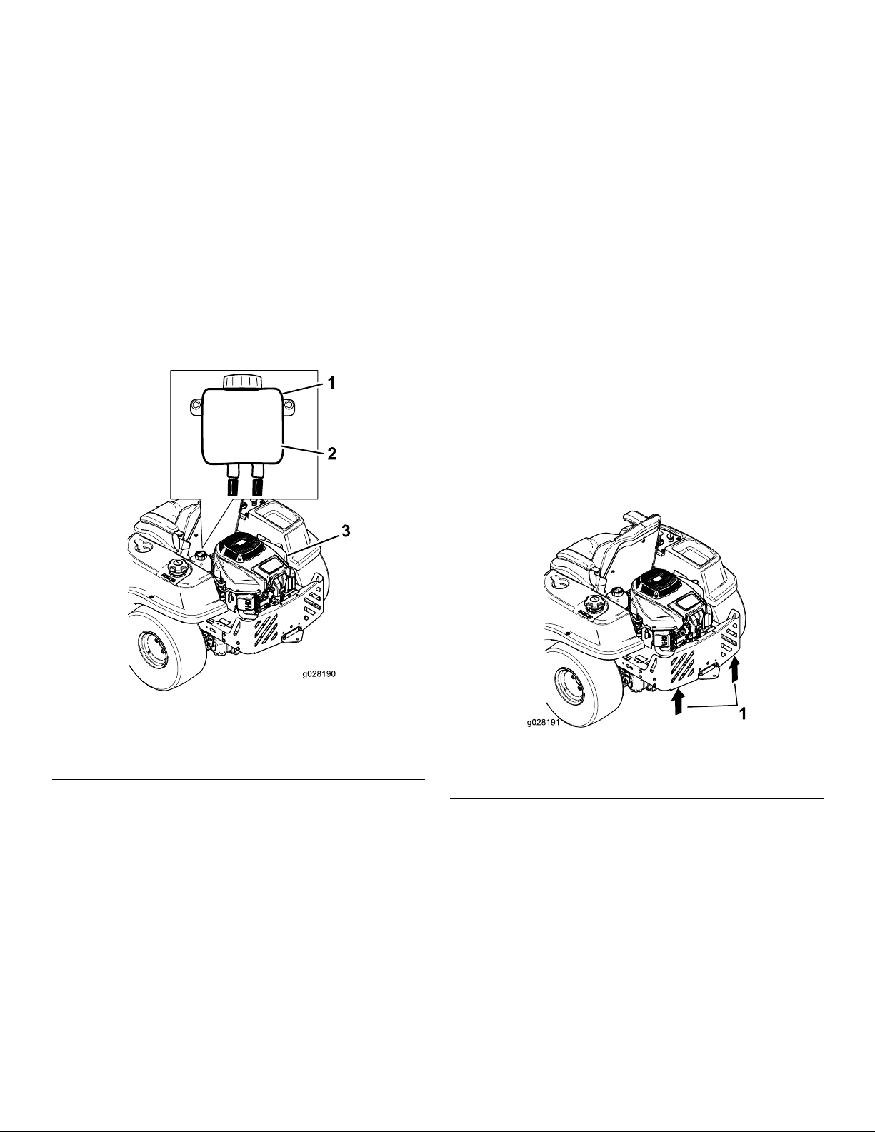
2.Raisetherearofmachineupandsupportwith
jackstands(orequivalentsupport)justhigh
enoughtoallowdrivewheelstoturnfreely.
Figure42
1.Expansionreservoir3.Engine
2.Fullcoldline
g028190
g028191
Figure43
1.Jackingpoints
3.Locatethelterandlterguardsoneach
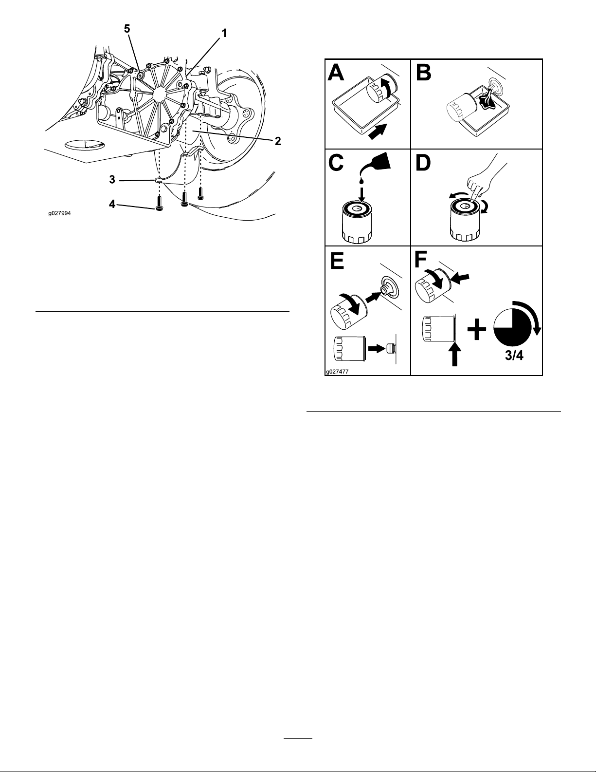
transaxledrivesystem(Figure44).Remove
threescrewssecuringthelterguardandguard.
38
Page 39
Rightsideshown
InstallingtheHydraulicSystem
Filters
g027994
Figure44
1.Transaxledrive
2.Oillter
3.Filterguard
4.Screws
5.Ventplug
4.Carefullycleanareaaroundlters.Itisimportant
thatnodirtorcontaminationenterhydraulic
system.
5.Placeacontainerbelowtheltertocatchthe
oilthatdrainswhenthelterandventplugsare
removed.
6.Locateandremovetheventplugoneach
transmission
7.Unscrewtheltertoremoveandallowoilto
drainfromdrivesystem.
Repeatthisprocedureforbothlters.
g027477
Figure45
1.Applyathincoatofthespeciedoilonthe
surfaceoftherubbersealofeachlter.
2.Turnthelterclockwiseuntilrubberseal
contactsthelteradapterthentightenthelter
anadditional3/4to1fullturn.Repeatforthe
otherlter
3.Installthelterguardsovereachlteras
previouslyremoved.Usethethreescrewsto
securethelterguards.
4.Verifytheventplugsareremovedbeforeadding
theoil(Figure44).
5.Slowlypourthespeciedoilthroughexpansion
reservoiruntiloilcomesoutofoneofthevent
plugholes.Stopandinstallthatventplug.
Torquetheplugto20.3N-m(180in-lb).
6.Continuetoaddoilthroughtheexpansion
reservoiruntiloilcomesoutoftheremaining
ventplugholeonthesecondtransmission.Stop
andinstallthatventplug.Torquetheplugto
20.3N-m(180in-lb).
7.Continuetoaddoilthroughtheexpansion
reservoiruntilitreachestheFullColdlineonthe
expansionreservoir.
39
Page 40

8.ProceedtotheBleedingtheHydraulicSystem
section.
Important:FailuretoperformtheBleeding
theHydraulicSystemprocedureafter
changinghydraulicltersandoilcanresult
inirreparabledamagetothetransaxledrive
system.
BleedingtheHydraulicSystem
1.Entertheoperator'sposition.Startengine
andmovethrottlecontrolaheadto1/2throttle
position.Disengageparkingbrake.
A.Movethebypassleversintothepushing
themachineposition;refertoPushingthe
MachinebyHand(page22).Withthe
bypassvalvesopenandtheenginerunning,
slowlymovethemotioncontrolpedalin
bothforwardandreverse(5or6times).
MowerMaintenance
ServicingtheCutting Blades
Maintainsharpbladesthroughoutthecuttingseason
becausesharpbladescutcleanlywithouttearingor
shreddingthegrassblades.Tearingandshredding
turnsgrassbrownattheedges,whichslowsgrowth
andincreasesthechanceofdisease.
Checkthecutterbladesdailyforsharpness,and
foranywearordamage.Filedownanynicksand
sharpenthebladesasnecessary.Ifabladeis
damagedorworn,replaceitimmediatelywitha
genuineTororeplacementblade.Forconvenient
sharpeningandreplacement,youmaywanttokeep
extrabladesonhand.
B.Movethebypassleversintotheoperating
themachineposition.Withthebypassvalve
closedandtheenginerunning,slowlymove
thetraction-controlpedalinbothforward
andreversedirections(5to6times).
C.Stoptheengineandchecktheoillevelin
theexpansionreservoir.Addthespecied
oilasuntilitreachestheFullColdlineon
theexpansionreservoir.
2.Repeatstep1untilalltheairiscompletely
purgedfromthesystem.
Whenthetransaxleoperatesatnormalnoise
levelsandmovessmoothlyforwardand
reverseatnormalspeeds,thenthetransaxleis
consideredpurged.
3.Checktheoillevelintheexpansionreservoir
onelasttime.Addthespeciedoilasuntilit
reachestheFullColdlineontheexpansion
reservoirifnecessary.
WARNING
Awornordamagedbladecanbreak,anda
pieceofthebladecouldbethrownintothe
operator'sorbystander'sarea,resultingin
seriouspersonalinjuryordeath.
•Inspectthebladeperiodicallyforwearor
damage.
•Replaceawornordamagedblade.
BeforeInspectingorServicingthe
Blades
Parkthemachineonalevelsurface,disengagethe
blade-controlswitch,andensuretheparkingbrakeis
engaged.Stoptheengineandremovethekey.
InspectingtheBlades
ServiceInterval:Beforeeachuseordaily—Check
thecuttingblades.
1.Inspectthecuttingedges(Figure46).Ifthe
edgesarenotsharporhavenicks,removeand
sharpentheblades;refertoSharpeningthe
Blades.
2.Inspecttheblades,especiallythecurvedarea
(Figure46).Ifyounoticeanydamage,wear,
oraslotforminginthisarea(items3and4in
Figure46),immediatelyinstallanewblade.
40
Page 41
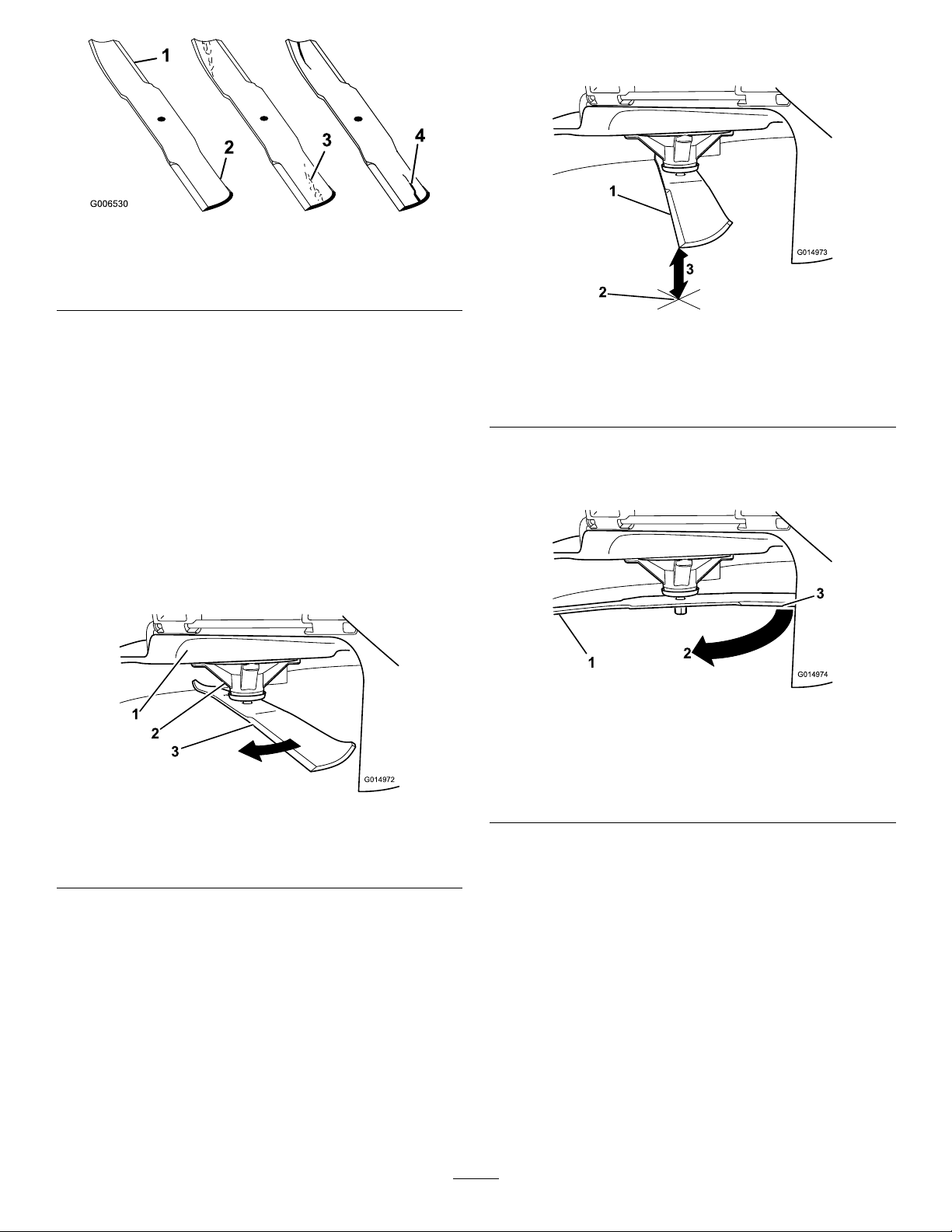
Figure46
1.Cuttingedge3.Wear/slotforming
2.Curvedarea
4.Damage
3.Measurefromthetipofthebladetotheat
surfacehere.
g006530
g014973
Figure48
CheckingforBentBlades
Note:Themachinemustbeonalevelsurfacefor
thefollowingprocedure.
1.Raisethemowerdecktothehighest
height-of-cutposition;alsoconsideredthe
'transport'position.
2.Whilewearingthicklypaddedglovesorother
adequatehandprotectionslowlyrotatebladeto
bemeasuredintoapositionthatallowseffective
measurementofthedistancebetweenthe
cuttingedgeandthelevelsurfacethemachine
ison.
Figure47
1.Blade,inpositionformeasuring
2.Levelsurface
3.Measureddistancebetweenbladeandsurface(A)
4.Rotatethesameblade180degreessothat
theopposingcuttingedgeisnowinthesame
position.
g014974
Figure49
1.Blade,sidepreviouslymeasured
2.Measurementpositionusedpreviously
3.Opposingsideofbladebeingmovedintomeasurement
g014972
position
1.Deck3.Blade
2.Spindlehousing
5.Measurefromthetipofthebladetotheat
surfacehere.Thevarianceshouldbenomore
than1/8inch(3mm).
41
Page 42
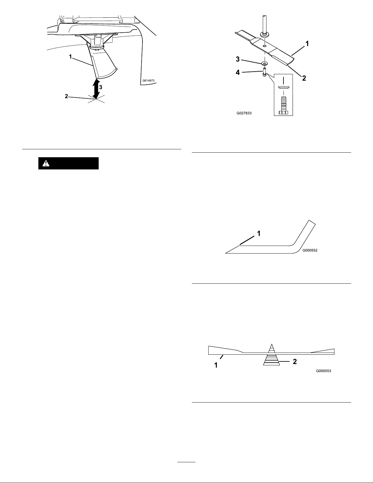
Figure50
1.Opposingbladeedge,inpositionformeasuring
2.Levelsurface
3.Secondmeasureddistancebetweenbladeandsurface(B)
WARNING
Abladethatisbentordamagedcould
breakapartandcouldseriouslyinjureor
killyouorbystanders.
•Alwaysreplacebentordamaged
bladewithanewblade.
•Neverleorcreatesharpnotchesin
theedgesorsurfacesofblade.
A.IfthedifferencebetweenAandBisgreater
than1/8inch(3mm)replacethebladewith
anewblade.RefertoRemovingtheBlades
andInstallingtheBlades.
Note:Ifabentbladeisreplacedwithanew
oneandthedimensionobtainedcontinues
toexceed1/8inch(3mm),thebladespindle
couldbebent.ContactanAuthorizedToro
Dealerforservice.
B.Ifthevarianceiswithinconstraints,moveto
thenextblade..
Repeatthisprocedureoneachblade.
g014973
g027833
Figure51
1.Sailareaofblade3.Curvedwasher
2.Blade4.Bladebolt
SharpeningtheBlades
1.Usealetosharpenthecuttingedgeatboth
endsoftheblade(Figure52).Maintainthe
originalangle.Thebladeretainsitsbalanceif
thesameamountofmaterialisremovedfrom
bothcuttingedges.
g000552
Figure52
1.Sharpenatoriginalangle
2.Checkthebalanceofthebladebyputtingiton
abladebalancer(Figure53).Ifthebladestays
inahorizontalposition,thebladeisbalanced
andcanbeused.Ifthebladeisnotbalanced,
lesomemetalofftheendofthesailareaonly
(Figure52).Repeatthisprocedureuntilthe
bladeisbalanced.
RemovingtheBlades
Thebladesmustbereplacedifasolidobjectishit,if
thebladeisoutofbalance,orthebladeisbent.To
ensureoptimumperformanceandcontinuedsafety
conformanceofthemachine,usegenuineT oro
replacementblades.Replacementbladesmadeby
othermanufacturersmayresultinnon-conformance
withsafetystandards.
Holdthebladeendusingaragorthickly-padded
glove.Removethebladebolt,curvedwasher,and
bladefromthespindleshaft(Figure51).
g000553
Figure53
1.Blade2.Balancer
InstallingtheBlades
1.Installthebladeontothespindleshaft(Figure
51).
42
Page 43
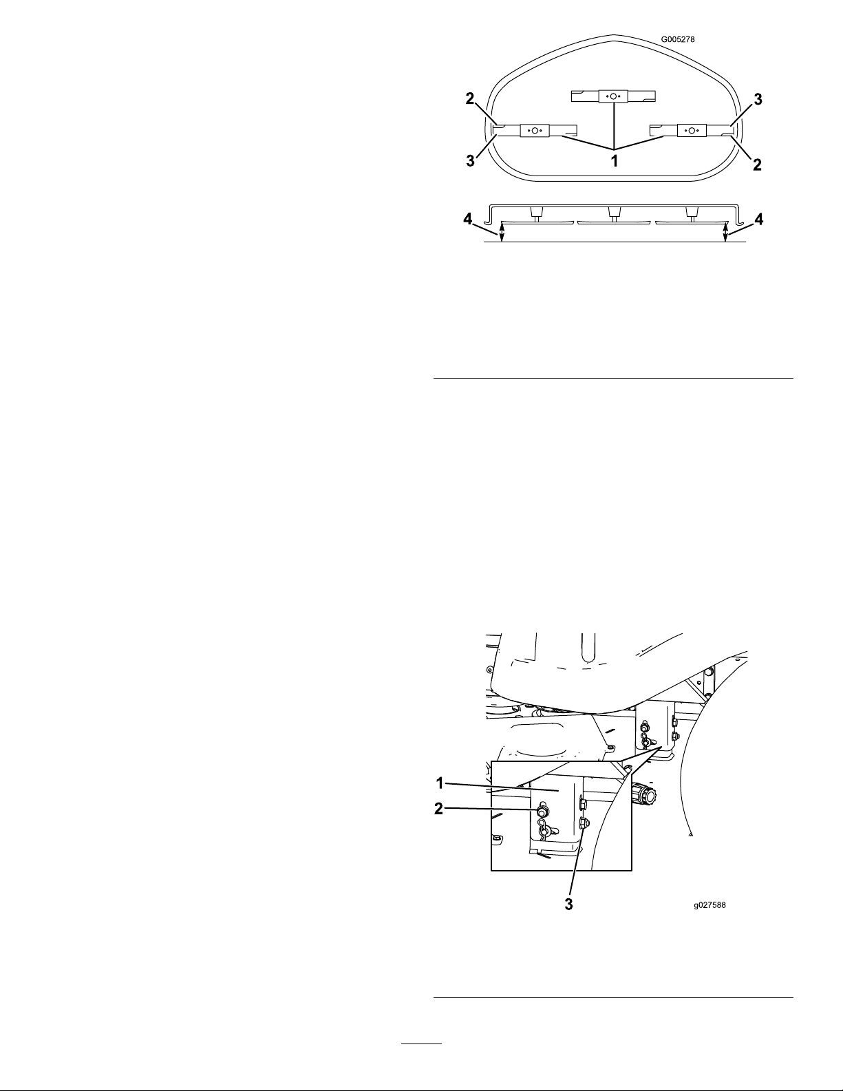
Important:Thecurvedpartoftheblade
mustbepointingupwardtowardtheinside
ofthemowertoensurepropercutting.
2.Installthecurvedwasher(cuppedsidetoward
theblade)andthebladebolt(Figure51).
3.T orquethebladeboltto35-65ft-lb(47-88N-m).
LevelingtheMowerDeck
Checktoensurethemowerdeckislevelanytimeyou
installthemowerorwhenyouseeanunevencuton
yourlawn.
Themowerdeckmustbecheckedforbentblades
priortoleveling;anybentbladesmustberemoved
andreplaced.RefertotheCheckingforBentBlades
(page41)beforecontinuing.
Themowerdeckmustbeleveledside-to-siderst
thenthefronttorearslopecanbeadjusted.
Requirements:
•Themachinemustbeonalevelsurface.
•Allfourtiremustbeproperlyinated.Referto
CheckingtheTirePressure(page37).
Figure54
Mowerdeckswith3blades
1.Bladesidetoside
2.Sailareaoftheblade4.Measurefromthetipofthe
3.Outsidecuttingedges
bladetotheatsurface
here
5.Measurebetweentheoutsidecuttingedges
andtheatsurface(Figure54).Ifboth
measurementsarenotwithin5mm(3/16inch),
anadjustmentisrequired;continuewiththis
procedure.
6.Movetotheleftsideofthemachine.
g005278
LevelingfromSidetoSide
1.Parkthemachineonalevelsurfaceand
disengagetheblade-controlswitch.
2.Ensuretheparkingbrakeisengaged,stopthe
engine,removethekey,andwaitforallmoving
partstostopbeforeleavingtheoperating
position.
3.Settheheight-of-cutlevertomiddleposition.
4.Carefullyrotatetheblade(s)sothattheyareall
sidetoside(Figure54).
7.Loosenthesidelockingnut.
8.Raiseorlowertheleftsideofthemowerdeck
byrotatingtherearnut.(Figure55).
Note:Rotatetherearnutclockwiseto
raisethemowerdeck;rotatetherearnut
counter-clockwisetolowerthemowerdeck.
Figure55
1.Hangerbracket3.Rear-lockingnut
2.Side-lockingnut
43
g027588
Page 44
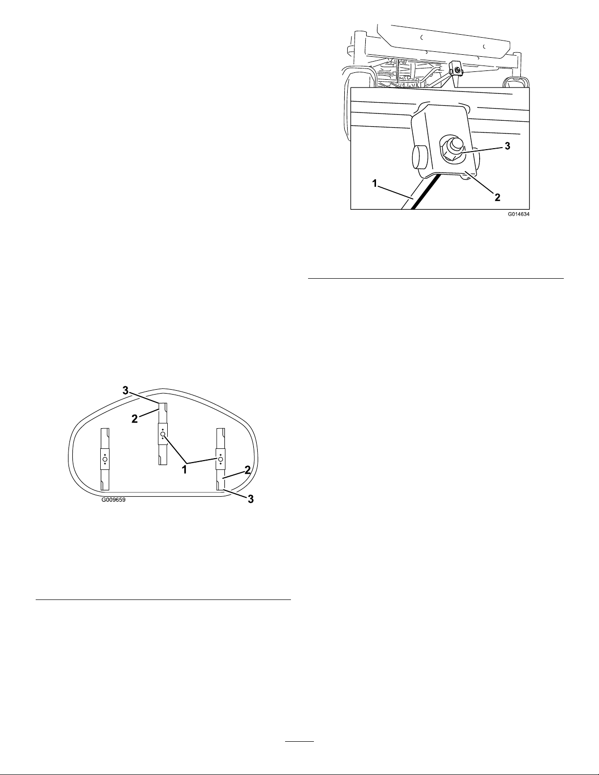
9.Checktheside-to-sideadjustmentsagain.
Repeatthisprocedureuntilthemeasurements
arecorrect.
10.Continuelevelingthedeckbycheckingthe
front-to-rearbladeslope;refertoAdjustingthe
Front-to-RearBladeSlope(page44).
AdjustingtheFront-to-RearBlade
Slope
Checkthefront-to-rearbladelevelanytimeyouinstall
themower.Ifthefrontofthemowerismorethan7.9
mm(5/16inch)lowerthantherearofthemower,
adjustthebladelevelusingthefollowinginstructions:
1.Parkthemachineonalevelsurfaceand
disengagetheblade-controlswitch.
2.Ensuretheparkingbrakeisengaged,stopthe
engine,removethekey,andwaitforallmoving
partstostopbeforeleavingtheoperating
position.
3.Settheheight-of-cutlevertomiddleposition.
Note:Checkandadjusttheside-to-sideblade
level.Ifyouhavenotcheckedthesetting;refer
toLevelingfromSidetoSide(page43).
4.Carefullyrotatethebladessotheyarefacing
fronttorear(Figure56).
Figure56
MowerDeckswith3Blades
g014634
Figure57
1.Adjustingrod3.Locknut
2.Adjustingblock
7.T oraisethefrontofthemower,tightenthe
adjustmentnut.T olowerthefrontofthemower,
loosentheadjustmentnut.
8.Afteradjustment,checkthefront-to-rearslope
again.Continueadjustingthenutuntilthefront
bladetipis1.6-7.9mm(1/16-5/16inch)lower
thantherearbladetip(Figure56).
9.Whenthefront-to-rearbladeslopeiscorrect
checktheside-to-sidelevelofthemoweragain;
refertoLevelingfromSidetoSide(page43).
RemovingtheMower
1.Parkthemachineonalevelsurfaceand
disengagetheblade-controlswitch.
2.Ensuretheparkingbrakeisengaged,stopthe
g009659
engine,removethekey,andwaitforallmoving
partstostopbeforeleavingtheoperating
position.
1.Bladesfronttorear3.Measurefromthetipofthe
bladetotheatsurface
here
2.Outsidecuttingedges
5.Measurefromthetipofthefrontbladetotheat
surfaceandthetipoftherearbladetotheat
surface(Figure56).Ifthefrontbladetipisnot
1.6-7.9mm(1/16-5/16inch)lowerthantherear
bladetip,adjustthefrontlocknut.
6.T oadjustthefront-to-rearbladeslope,rotatethe
adjustmentnutinthefrontofthemower(Figure
57).
3.Lowertheheight-of-cutlevertothelowest
position.
4.Removethehairpincotterfromthefrontsupport
rodandremovetherodfromthedeckbracket
(Figure58).Carefullylowerthefrontofthe
mowerdecktotheground.
44
Page 45
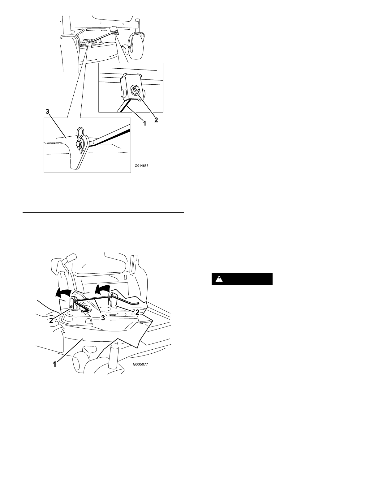
Note:Retainallpartsforfutureinstallation.
MowerBeltMaintenance
InspectingtheBelts
ServiceInterval:Every25hours—Checkthebelts
forwear/cracks.
Checkthebeltsforcracks,frayededges,burnmarks,
oranyotherdamage.Replacedamagedbelts.
ReplacingtheMowerBelt
Squealingwhenthebeltisrotating,bladesslipping
whencuttinggrass,frayedbeltedges,burnmarks,
andcracksaresignsofawornmowerbelt.Replace
themowerbeltifanyoftheseconditionsareevident.
Figure58
1.Frontsupportrod3.Deckbracket
2.Lockingnut
5.Usingthemowerdeckhandles,liftthemower
deckandhangerbracketsclearoftherearlift
rodandlowerthemowercarefullytotheground
(Figure59andFigure60).
g014635
1.Parkthemachineonalevelsurfaceand
disengagetheblade-controlswitch.
2.Ensuretheparkingbrakeisengaged,stopthe
engine,removethekey,andwaitforallmoving
partstostopbeforeleavingtheoperating
position.
3.Settheheight-of-cutatthelowestcutting
position[1-1/2inch(38mm)].
4.Usingaspringremovaltool,(T oropartno.
92-5771),removetheidlerspringfromthedeck
hooktoremovetensionontheidlerpulleyand
rollthebeltoffofthepulleys(Figure60).
WARNING
Thespringisundertensionwhen
installedandcancausepersonalinjury .
Becarefulwhenremovingthebelt.
Figure59
1.Mowerdeck
2.Hangerbracket
6.Slidethemowerdeckrearwardtoremovethe
mowerbeltfromtheenginepulley.
7.Slidethemowerdeckoutfromunderneaththe
machine.
3.Rearliftrod
g005077
45
Page 46
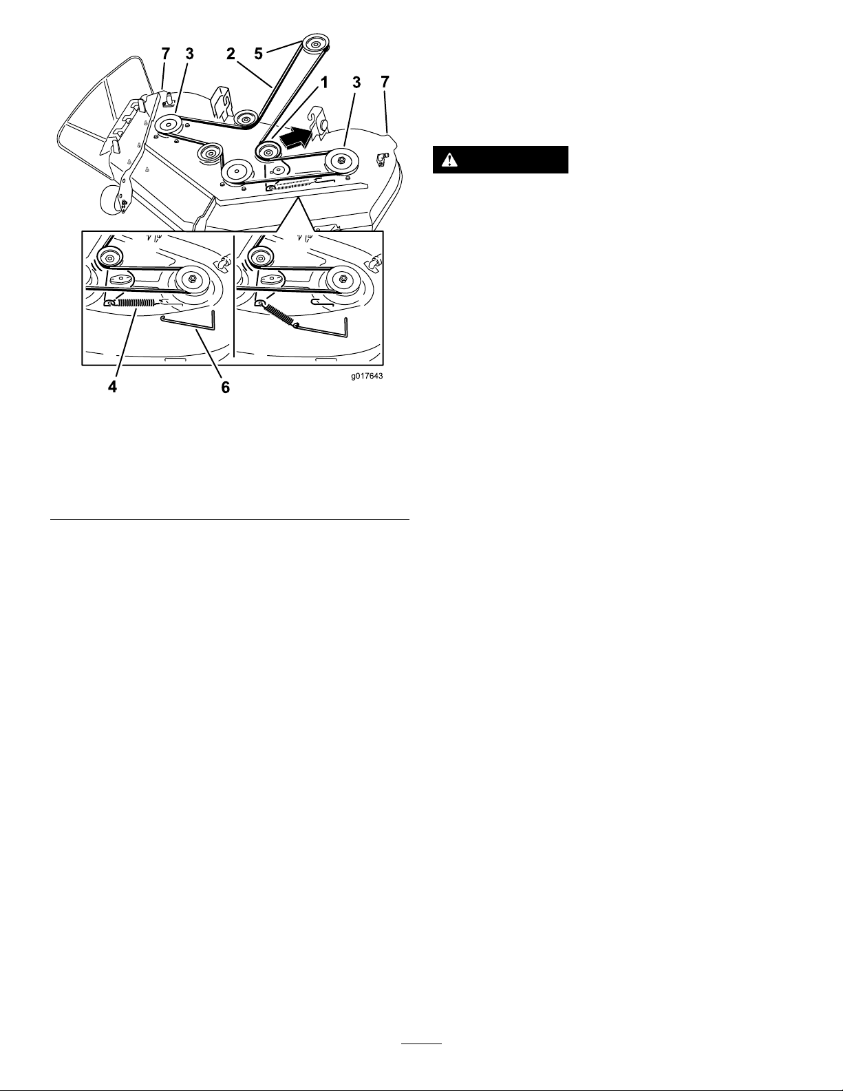
Figure60
1.Idlerpulley5.Enginepulley
2.Mowerbelt
3.Outsidepulley
4.Spring
6.Springremovaltoo
7.Mowerdeckhandles
ReplacingtheGrass
Deector
ServiceInterval:Beforeeachuseordaily—Inspect
thegrassdeectorfordamage.
WARNING
Anuncovereddischargeopeningcould
allowthelawnmowertothrowobjectsinthe
operator’sorbystander’sdirectionandresult
inseriousinjury.Also,contactwiththeblade
couldoccur.
Neveroperatethelawnmowerunlessyou
installamulchplate,dischargedeector,or
grasscollectionsystem.
Inspectthegrassdeectorfordamagebeforeeach
use.Replaceanydamagedpartsbeforeuse.
g017643
1.Disengagethespringfromthenotchinthe
deectorbracketandslidetherodoutofthe
weldeddeckbrackets,spring,anddischarge
deector(Figure61).Removethedamagedor
worndischargedeector.
5.Routethenewbeltaroundtheenginepulleyand
mowerpulleys(Figure60).
6.Usingaspringremovaltool,(T oropartno.
92-5771),installtheidlerspringoverthedeck
hookandplacingtensionontheidlerpulleyand
mowerbelt(Figure60).
InstallingtheMower
1.Parkthemachineonalevelsurfaceand
disengagetheblade-controlswitch.
2.Ensuretheparkingbrakeisengaged,stopthe
engine,removethekey,andwaitforallmoving
partstostopbeforeleavingtheoperating
position.
3.Slidethemowerunderthemachine.
4.Lowertheheight-of-cutlevertothelowest
position.
5.Lifttherearofthemowerdeckandguidethe
hangerbracketsovertherearliftrod(Figure59).
6.Attachthefrontsupportrodtothemowerdeck
withtheclevispinandhairpincotter(Figure58).
7.Installthemowerbeltontotheenginepulley;
refertoReplacingtheMowerBelt(page45).
46
Page 47
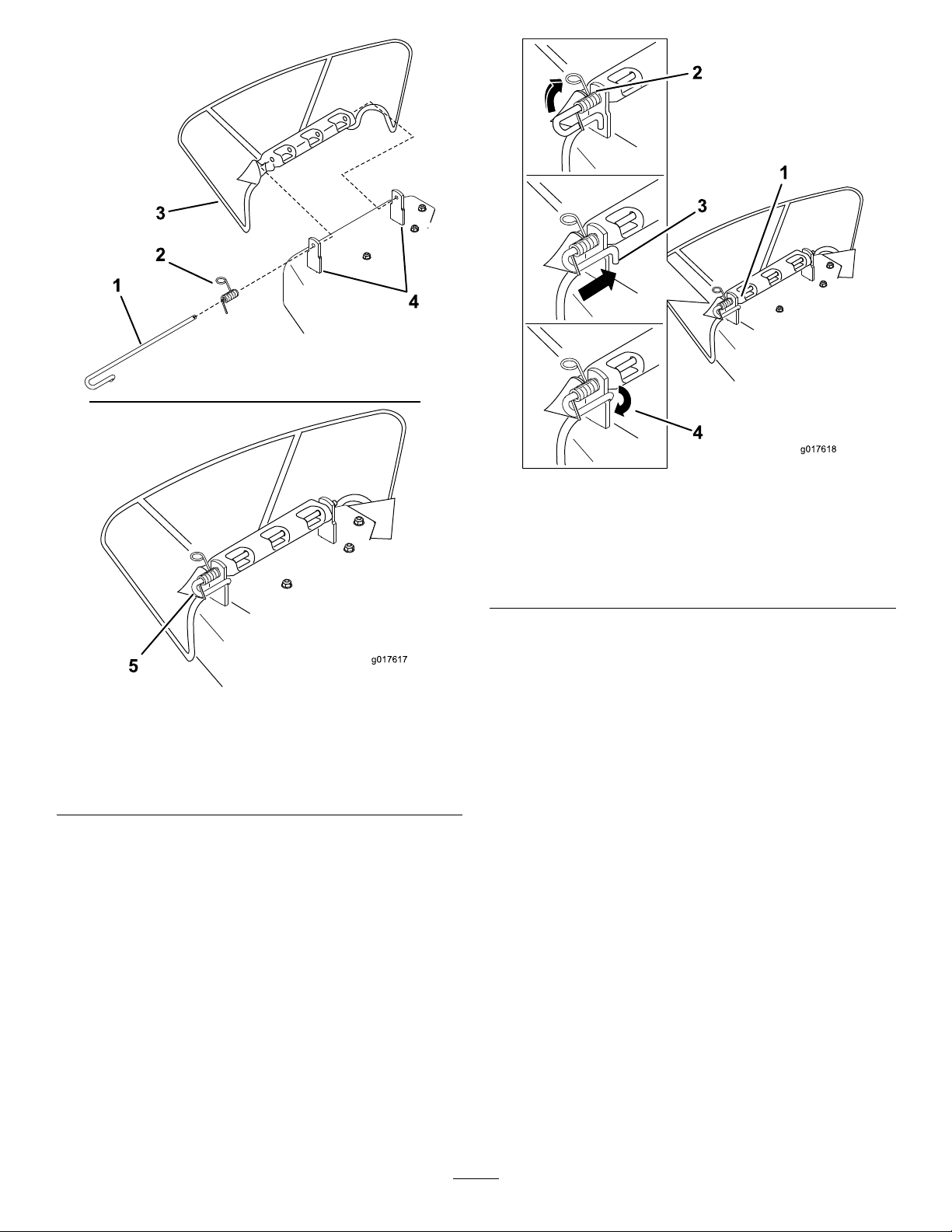
Figure62
g017618
Figure61
1.Rod4.Deckbrackets
2.Spring5.Springinstalledoverthe
rod
3.Deector
2.Positionthenewdischargedeectorwiththe
bracketendsbetweentheweldedbracketson
thedeckasshowninFigure61.
3.Installthespringontothestraightendoftherod.
Positionthespringontherodasshowninso
theshorterspringendiscomingfromunderthe
rodbeforethebendandgoingovertherodasit
returnsfromthebend.
1.Rodandspringassembly
installed
2.Loopendofthespring
installedintothenotchin
thedeectorbracket
3.Rod,shortend,moved
behindmowerbracket
4.Shortend,retainedby
mowerbracket.
5.Securetherodandspringassemblybytwistingit
sotheshortendoftherodcanbeplacedbehind
thefrontbracketweldedtothedeck(Figure62).
g017617
Important:Thegrassdeectormustbe
springloadedinthedownposition.Liftthe
deectoruptotestthatitsnapstothefull
downposition.
4.Lifttheloopendofthespringandplaceitinto
thenotchonthedeectorbracket(Figure62).
47
Page 48
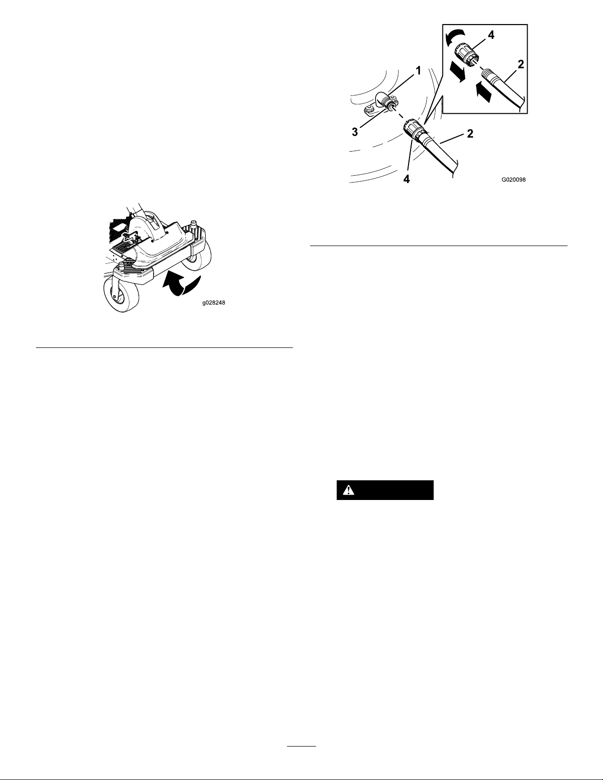
Cleaning
CleaningundertheFrontof theMachine
ServiceInterval:Aftereachuse—Checkandclean
thefrontofthemower.
Removedebrisunderthefrontofthemachinewith
compressedairorbyhandwithabrush(Figure63).
Note:Donotusewatertocleanunderthefrontofthe
machine,thiscancausebuildupofdebris.
Figure63
WashingtheUndersideof theMowerDeck
ServiceInterval:Aftereachuse—Cleanthemower
housing.
Important:Youcanwashthemachinewithmild
detergentandwater.Donotpressurewashthe
machine.Avoidexcessiveuseofwater,especially
nearthecontrolpanel,undertheseat,aroundthe
engine,hydraulicpumps,andmotors.
Washtheundersideofthemoweraftereachuseto
preventgrassbuildupforimprovedmulchactionand
clippingdispersal.
1.Parkthemachineonalevelsurfaceand
disengagetheblade-controlswitch.
2.Ensuretheparkingbrakeisengaged,stopthe
engine,removethekey,andwaitforallmoving
partstostopbeforeleavingtheoperating
position.
3.Attachthehosecouplingtotheendofthe
mowerwashouttting,andturnthewateron
high(Figure64).
g020098
Figure64
1.Washouttting3.O-ring
2.Hose
4.Lowerthemowertothelowestheight-of-cut.
5.Sitontheseatandstarttheengine.Engagethe
blade-controlswitchandletthemowerrunfor
onetothreeminutes.
g028248
6.Disengagetheblade-controlswitch,stopthe
engine,andremovetheignitionkey.Waitforall
movingpartstostop.
7.Turnthewateroffandremovethecouplingfrom
thewashouttting.
4.Coupling
Note:Ifthemowerisnotcleanafterone
washing,soakitandletitstandfor30minutes.
Thenrepeattheprocess.
8.Runthemachineandmowerbladesagainfor
onetothreeminutestoremoveexcesswater.
9.Turnoffthemowerblades.
WARNING
Abrokenormissingwashouttting
couldexposeyouandotherstothrown
objectsorbladecontact.Contactwith
bladeorthrowndebriscancauseinjury
ordeath.
•Replacebrokenormissingwashout
ttingimmediately,beforeusing
moweragain.
•Neverputyourhandsorfeetunder
themowerorthroughopeningsinthe
mower.
Note:Spreadpetroleumjellyonthewashout
ttingO-ringtomakethecouplingslideon
easierandprotecttheO-ring.
48
Page 49

Storage
CleaningandStorage
1.Disengagetheblade-controlswitch,ensurethe
parkingbrakeisengaged,stoptheengine,and
removethekey.
2.Removegrassclippings,dirt,andgrimefromthe
externalpartsoftheentiremachine,especially
theengine.Cleandirtandchafffromtheoutside
oftheenginecylinderheadnsandblower
housing.
Important:Youcanwashthemachinewith
milddetergentandwater.Donotpressure
washthemachine.Avoidexcessiveuse
ofwater,especiallynearthecontrolpanel,
undertheseat,aroundtheengine,hydraulic
pumps,andmotors.
3.Servicetheaircleaner;refertoServicingtheAir
Cleaner(page29).
4.Greaseandoilthemachine;refertoLubrication
(page28).
cylinder.Installthesparkplug(s).Donotinstall
thewireonthesparkplug(s).
12.Cleananydirtandchafffromthetopofthe
mower.
13.Scrapeanyheavybuildupofgrassanddirt
fromtheundersideofthemower,thenwashthe
mowerwithagardenhose.
14.Checktheconditionofthedriveandmower
belts.
15.Checkandtightenallbolts,nuts,andscrews.
Repairorreplaceanypartthatiswornor
damaged.
16.Paintallscratchedorbaremetalsurfaces.Paint
isavailablefromyourAuthorizedServiceDealer.
17.Storethemachineinaclean,drygarageor
storagearea.Removethekeyfromtheignition
switchandkeepitinamemorableplace.Cover
themachinetoprotectitandkeepitclean.
5.Changethecrankcaseoilandlter;referto
ChangingtheEngineOilandOilFilter(page30).
6.Checkthetirepressure;refertoCheckingthe
TirePressure(page37).
7.Chargethebattery;refertoChargingtheBattery
(page35).
8.Checktheconditionoftheblades;referto
ServicingtheCuttingBlades(page40).
9.Preparethemachineforstoragewhennon-use
occursover30days.Preparethemachinefor
storageasfollows.
10.Addapetroleumbasedstabilizer/conditioner
tothefuelinthetank.Followthemixing
instructionsfromthestabilizermanufacturer.Do
notuseanalcoholbasedstabilizer(ethanolor
methanol).
Note:Afuelstabilizer/conditionerismost
effectivewhenmixedwithfreshgasolineand
usedatalltimes.
Runtheenginetodistributetheconditionedfuel
throughthefuelsystem(5minutes).
Important:Donotstore
stabilizer/conditionedgasolineover90days.
11.Removethesparkplug(s)andcheckits
condition;refertoServicingtheSparkPlug
(page32).Withthesparkplug(s)removedfrom
theengine,pourtwotablespoonsofengine
oilintothesparkplughole.Usethestarterto
cranktheengineanddistributetheoilinsidethe
49
Page 50

Troubleshooting
Problem
Theengineoverheats.
Thestarterdoesnotcrank.
Theenginedoesnotstart,startshard,or
failstokeeprunning.
PossibleCauseCorrectiveAction
1.Theengineloadisexcessive.1.Reducegroundspeed.
2.Theoillevelinthecrankcaseislow.2.Addoiltothecrankcase.
3.Thecoolingnsandairpassages
undertheengineblowerhousingare
plugged.
4.Theaircleanerisdirty.
5.Dirt,water,orstalefuelisinfuel
system.
1.Theblade-controlswitchisengaged.1.Movetheblade-controlswitchto
2.Thebatteryisdead.
3.Theelectricalconnectionsare
corrodedorloose.
4.Afuseisblown.4.Replacethefuse.
5.Arelayorswitchisdamaged.
1.Thefueltankisempty.1.Fillthefueltank.
2.Thechokeisnoton.
3.Theaircleanerisdirty.
4.Thesparkplugwire(s)islooseor
disconnected.
5.Thesparkplug(s)ispitted,fouled,or
thegapisincorrect.
6.Thereisdirtinfuellter.6.Replacethefuellter.
7.Dirt,water,orstalefuelisinfuel
system.
8.Thereisincorrectfuelinthefueltank.
9.Theoillevelinthecrankcaseislow.9.Addoiltothecrankcase.
3.Removetheobstructionfromthe
coolingnsandairpassages.
4.Cleanorreplacetheaircleaner
element.
5.ContactanAuthorizedServiceDealer
Disengaged.
2.Chargethebattery.
3.Checktheelectricalconnectionsfor
goodcontact.
5.ContactanAuthorizedServiceDealer.
2.MovethechokelevertoOn.
3.Cleanorreplacetheaircleaner
element.
4.Installthewire(s)onthesparkplug.
5.Installanew,correctlygappedspark
plug(s).
7.ContactanAuthorizedServiceDealer.
8.Drainthetankandreplacethefuelwith
thepropertype.
Theenginelosespower.
Themachinedoesnotdrive.
1.Theengineloadisexcessive.1.Reducegroundspeed.
2.Theaircleanerisdirty.
3.Theoillevelinthecrankcaseislow.3.Addoiltothecrankcase.
4.Thecoolingnsandairpassages
undertheengineblowerhousingare
plugged.
5.Thesparkplug(s)ispitted,fouled,or
thegapisincorrect.
6.Thefueltankventisblocked.6.ContactanAuthorizedServiceDealer.
7.Thereisdirtinthefuellter.7.Replacethefuellter .
8.
Dirt,water ,orstalefuelisinthefuel
system.
9.Thereisincorrectfuelinthefueltank.
1.Thebypassvalvesareopen.
2.Thetractionbeltsareworn,loose,or
broken.
3.
Thetractionbeltsareoffofthepulleys.
4.Thetransmissionhasfailed.4.ContactanAuthorizedServiceDealer.
2.Cleantheaircleanerelement.
4.Removetheobstructionfromthe
coolingnsandairpassages.
5.Installanew,correctlygappedspark
plug(s).
8.ContactanAuthorizedServiceDealer.
9.
Drainthetankandreplacethefuelwith
thepropertype.
1.Closethetowvalves.
2.ContactanAuthorizedServiceDealer.
3.
ContactanAuthorizedServiceDealer.
50
Page 51

Problem
PossibleCauseCorrectiveAction
Thereisabnormalvibration.
Thecuttingheightisuneven.
Thebladesdonotrotate.
1.Theenginemountingboltsareloose.1.Tightentheenginemountingbolts.
2.Theenginepulley ,idlerpulley,orblade
pulleyisloose.
3.Theenginepulleyisdamaged.
4.Thecuttingblade(s)is/arebentor
unbalanced.
5.Ablademountingboltisloose.5.Tightentheblademountingbolt.
6.Abladespindleisbent.
1.Theblade(s)isnotsharp.1.Sharpentheblade(s).
2.Acuttingblade(s)is/arebent.2.Installanewcuttingblade(s).
3.Themowerisnotlevel.
4.Ananti-scalpwheelisnotsetcorrectly.4.Adjusttheanti-scalpwheelheight.
5.Theundersideofthemowerisdirty.5.Cleantheundersideofthemower.
6.Thetirepressureisincorrect.6.Adjustthetirepressure.
7.Abladespindleisbent.
1.Thedrivebeltisworn,looseorbroken.1.Installanewdrivebelt.
2.Thedrivebeltisoffofthepulley .
3.ThePowerTake-Off(PTO)switchor
PTOclutchisfaulty.
4.Themowerbeltisworn,loose,or
broken.
2.Tightentheappropriatepulley.
3.ContactanAuthorizedServiceDealer.
4.Installanewcuttingblade(s).
6.ContactanAuthorizedServiceDealer.
3.Levelthemowerfromside-to-sideand
front-to-rear.
7.ContactanAuthorizedServiceDealer.
2.Installthedrivebeltandcheckthe
adjustingshaftsandbeltguidesforthe
correctposition.
3.ContactanAuthorizedServiceDealer.
4.Installanewmowerbelt.
51
Page 52
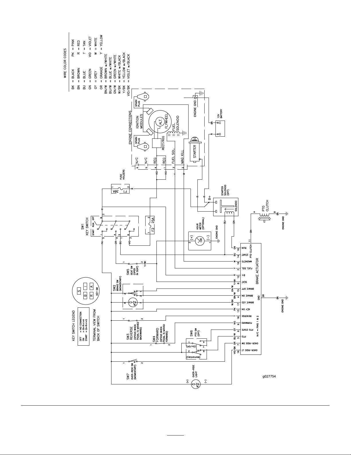
Schematics
ElectricalDiagram(Rev .A)
52
g027754
Page 53

Notes:
Page 54

Notes:
Page 55

Notes:
Page 56

TheT oroTotalCoverageWarranty
LimitedWarranty(seewarrantyperiodsbelow)
TimeCutter
and
TITAN
Mowers
ConditionsandProductsCovered
TheT oroCompanyanditsafliate,T oroWarrantyCompany ,pursuanttoan
agreementbetweenthem,jointlypromisetotheoriginalpurchasertorepair
theT oroProductslistedbelowifdefectiveinmaterialsorworkmanship.
Thefollowingtimeperiodsapplyfromthedateofpurchasebytheoriginal
owner:
ProductsWarrantyPeriod
TimeCutterandMXMowers
•Engines
1
Residentialuse
—ResidentialuseKawasaki–3years
2
–3years
Kohler–3years
Toro–3years
TimeCutterandMXMowersCommercialuse30days
•Engines
1
—Commercialuse
Kawasaki–3years
Kohler–90days
Toro–90days
TITANMowers–Residentialor
Commercialuse
•Engines
1
—Residentialor
Commercialuse
•Frame
TITANMX5400andMX600Mowers
–ResidentialorCommercialuse
•Engines
1
—Residentialor
Commercialuse
•Frame
3yearsor300hours
Kawasaki–3years
Lifetime(originalowneronly)
4yearsor400hours
Kawasaki–3years
Lifetime(originalowneronly)
3
4
3
4
AllMowers
•Attachments1year
•Battery90daysPartsandLabor
1yearPartsonly
•BeltsandTires90days
1
SomeenginesusedonT oroProductsarewarrantedbytheenginemanufacturer .
2
Residentialusemeansuseoftheproductonthesamelotasyourhome.Useatmorethanone
locationisconsideredcommercialuseandthecommercialusewarrantywouldapply .
3
Whicheveroccursrst.
4
LifetimeFrameWarranty-Ifthemainframe,consistingofthepartsweldedtogethertoformthe
tractorstructurethatothercomponentssuchastheenginearesecuredto,cracksorbreaksin
normaluse,itwillberepairedorreplaced,atT oro'soption,underwarrantyatnocostforpartsand
labor.Framefailureduetomisuseorabuseandfailureorrepairrequiredduetorustorcorrosion
arenotcovered.
Warrantymaybedeniedifthehourmeterisdisconnected,altered,or
showssignsofbeingtamperedwith.
OwnerResponsibilities
YoumustmaintainyourToroProductbyfollowingthemaintenance
proceduresdescribedintheOperator'sManual.Suchroutinemaintenance,
whetherperformedbyadealerorbyyou,isatyourexpense.
InstructionsforObtainingWarrantyService
IfyouthinkthatyourT oroProductcontainsadefectinmaterialsor
workmanship,followthisprocedure:
1.ContactanyAuthorizedT oroServiceDealertoarrangeserviceattheir
dealership.T olocateadealerconvenienttoyou,refertotheYellow
Pagesofyourtelephonedirectory(lookunder“LawnMowers”)or
accessourwebsiteatwww.T oro.com.Youmayalsocallthenumbers
listedinitem#3tousethe24-hourT oroDealerlocatorsystem.
2.Bringtheproductandyourproofofpurchase(salesreceipt)tothe
ServiceDealer.Thedealerwilldiagnosetheproblemanddetermineif
itiscoveredunderwarranty.
3.IfforanyreasonyouaredissatisedwiththeServiceDealer’s
analysisorwiththeassistanceprovided,contactusat:
CustomerCareDepartment,RLCDivision
ToroWarrantyCompany
811 1LyndaleAvenueSouth
Bloomington,MN55420-1196
Tollfreeat866-216-6029(U.S.customers)
Tollfreeat866-216-6030(Canadiancustomers)
ItemsandConditionsNotCovered
Thereisnootherexpresswarrantyexceptforspecialemissionsystem
coverageandenginewarrantycoverageonsomeproducts.Thisexpress
warrantydoesnotcoverthefollowing:
•Costofregularmaintenanceserviceorparts,suchaslters,fuel,
lubricants,oilchanges,sparkplugs,airltersbladesharpeningorworn
blades,cable/linkageadjustments,orbrakeandclutchadjustments
•Componentsfailingduetonormalwear
•Anyproductorpartwhichhasbeenalteredormisusedorneglected
andrequiresreplacementorrepairduetoaccidentsorlackofproper
maintenance
•Pickupanddeliverycharges
•RepairsorattemptedrepairsbyanyoneotherthananAuthorizedT oro
ServiceDealer
•Repairsnecessaryduetofailuretofollowrecommendedfuel
procedure(consultOperator'sManualformoredetails)
–Removingcontaminantsfromthefuelsystemisnotcovered
–Useofoldfuel(morethanonemonthold)orfuelwhichcontains
morethan10%ethanolormorethat15%MTBE
–Failuretodrainthefuelsystempriortoanyperiodofnon-use
overonemonth
GeneralConditions
AllrepairscoveredbythesewarrantiesmustbeperformedbyanAuthorized
ToroServiceDealerusingT oroapprovedreplacementparts.
NeitherTheToroCompanynorToroWarrantyCompanyisliablefor
indirect,incidentalorconsequentialdamagesinconnectionwiththe
useoftheToroProductscoveredbythiswarranty,includingany
costorexpenseofprovidingsubstituteequipmentorserviceduring
reasonableperiodsofmalfunctionornon-usependingcompletionof
repairsunderthiswarranty.
Allimpliedwarrantiesofmerchantability(thattheproductistfor
ordinaryuse)andtnessforuse(thattheproductistforaparticular
purpose)arelimitedtothedurationoftheexpresswarranty.
Somestatesdonotallowexclusionsofincidentalorconsequential
damages,orlimitationsonhowlonganimpliedwarrantylasts,sothe
aboveexclusionsandlimitationsmaynotapplytoyou.
Thiswarrantygivesyouspeciclegalrights,andyoumayalsohaveother
rightswhichvaryfromstatetostate.
CountriesOtherthantheUnitedStatesorCanada
CustomerswhohavepurchasedT oroproductsoutsidetheUnitedStatesorCanadashouldcontacttheirT oroDistributor(Dealer)toobtainguarantee
policiesforyourcountry,province,orstate.IfforanyreasonyouaredissatisedwithyourDistributor'sserviceorhavedifcultyobtainingguarantee
information,contacttheT oroimporter.Ifallotherremediesfail,youmaycontactusatT oroWarrantyCompany.
AustralianConsumerLaw:AustraliancustomerswillnddetailsrelatingtotheAustralianConsumerLaweitherinsidetheboxoratyourlocalToro
Dealer.
374-0258RevE
 Loading...