

Page 1
FormNo.3413-560RevA
TimeCutter
®
MX4250,MX5050,
MX6050,orSS5425Riding
Mower
ModelNo.74741—SerialNo.400000000andUp
ModelNo.74760—SerialNo.400000000andUp
ModelNo.74771—SerialNo.400000000andUp
ModelNo.74777—SerialNo.400000000andUp
Registeratwww.T oro.com.
OriginalInstructions(EN)
*3413-560*A
Page 2
WARNING
CALIFORNIA
Proposition65Warning
Thisproductcontainsachemicalorchemicals
knowntotheStateofCaliforniatocausecancer,
birthdefects,orreproductiveharm.
Theengineexhaustfromthisproduct
containschemicalsknowntotheStateof
Californiatocausecancer,birthdefects,
orotherreproductiveharm.
ThissparkignitionsystemcomplieswithCanadianICES-002
ItisaviolationofCaliforniaPublicResourceCode
Section4442or4443touseoroperatetheengineonany
forest-covered,brush-covered,orgrass-coveredlandunless
theengineisequippedwithasparkarrester,asdenedin
Section4442,maintainedineffectiveworkingorderorthe
engineisconstructed,equipped,andmaintainedforthe
preventionofre.
GrossHorsepower
Thegrossornethorsepowerofthisenginewaslaboratory
ratedbytheenginemanufacturerinaccordancewiththe
SocietyofAutomotiveEngineers(SAE)J1940.Ascongured
tomeetsafety,emission,andoperatingrequirements,
theactualenginetorqueonthisclassofmowerwillbe
signicantlylower.
Gotowww .Toro.comtoviewspecicationsonyourmower
model.
Important:IfyouareusingamachinewithaT oro
engineabove1500m(5,000ft)foracontinuousperiod,
ensurethattheHighAltitudeKithasbeeninstalledso
thattheenginemeetsCARB/EPAemissionregulations.
TheHighAltitudeKitincreasesengineperformance
whilepreventingspark-plugfouling,hardstarting,and
increasedemissions.Onceyouhaveinstalledthekit,
attachthehigh-altitudelabelnexttotheserialdecal
onthemachine.ContactanyAuthorizedToroService
DealertoobtaintheproperHighAltitudeKitand
high-altitudelabelforyourmachine.Tolocateadealer
convenienttoyou,accessourwebsiteatwww .Toro.com
orcontactourToroCustomerCareDepartmentatthe
number(s)listedinyourEmissionControlWarranty
Statement.
Removethekitfromtheengineandrestoretheengine
toitsoriginalfactorycongurationwhenrunningthe
engineunder1500m(5,000ft).Donotoperateanengine
thathasbeenconvertedforhigh-altitudeuseatlower
altitudes;otherwise,youcouldoverheatanddamage
theengine.
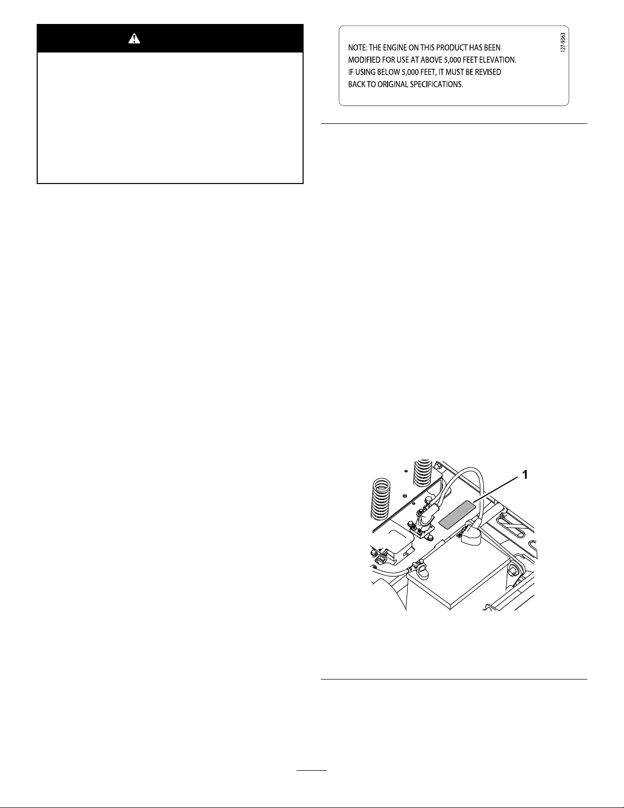
Ifyouareunsurewhetherornotyourmachinehasbeen
convertedforhigh-altitudeuse,lookforthefollowing
label.
decal127-9363
Introduction
Thismachineisaride-on,rotary-bladelawnmowerintended
tobeusedbyhomeownersinresidentialapplications.Itis
primarilydesignedforcuttinggrassonwell-maintainedlawns.
Itisnotdesignedforcuttingbrush,mowinggrassandother
growthalongsidehighways,orforagriculturaluses.
Readthisinformationcarefullytolearnhowtooperateand
maintainyourproductproperlyandtoavoidinjuryand
productdamage.Youareresponsibleforoperatingthe
productproperlyandsafely.
YoumaycontactTorodirectlyatwww .Toro.comforproduct
safetyandoperationtrainingmaterials,accessoryinformation,
helpndingadealer,ortoregisteryourproduct.
Wheneveryouneedservice,genuineT oroparts,oradditional
information,contactanAuthorizedServiceDealerorToro
CustomerServiceandhavethemodelandserialnumbersof
yourproductready.Figure1identiesthelocationofthe
modelandserialnumbersontheproduct.Writethenumbers
inthespaceprovided.
g188142
Figure1
Undertheseat
1.Modelandserialnumberplate
Writetheproductmodelandserialnumbersinthespace
below:
©2017—TheToro®Company
8111LyndaleAvenueSouth
Bloomington,MN55420
Contactusatwww.Toro.com.
2
PrintedintheUSA
AllRightsReserved
Page 3

ModelNo.
SerialNo.
Thismanualidentiespotentialhazardsandhassafety
messagesidentiedbythesafety-alertsymbol(Figure2),
whichsignalsahazardthatmaycauseseriousinjuryordeath
ifyoudonotfollowtherecommendedprecautions.
Figure2
1.Safety-alertsymbol.
Thismanualuses2wordstohighlightinformation.
Importantcallsattentiontospecialmechanicalinformation
andNoteemphasizesgeneralinformationworthyofspecial
attention.
Contents
Safety...........................................................................4
GeneralSafety.........................................................4
SlopeIndicator.......................................................5
SafetyandInstructionalDecals.................................6
ProductOverview.........................................................14
Controls...............................................................14
BeforeOperation......................................................16
BeforeOperationSafety..........................................16
RecommendedFuel................................................16
UsingStabilizer/Conditioner...................................17
FillingtheFuelTank...............................................17
g000502
CheckingtheEngine-OilLevel.................................17
BreakinginaNewMachine......................................17
ThinkSafetyFirst...................................................17
UsingtheSafety-InterlockSystem.............................18
PositioningtheSeat................................................19
AdjustingtheMotion-ControlLevers........................19
DuringOperation.....................................................20
DuringOperationSafety.........................................20
OperatingtheMowerBlade-ControlSwitch
(PTO)...............................................................21
OperatingtheThrottle............................................21
OperatingtheChoke...............................................21
OperatingtheIgnitionSwitch..................................22
StartingandShuttingOfftheEngine.........................22
UsingtheMotion-ControlLevers.............................23
DrivingtheMachine...............................................23
StoppingtheMachine.............................................24
AdjustingtheHeightofCut.....................................25
AdjustingtheAnti-ScalpRollers...............................25
UsingtheSideDischarge.........................................26
UsingAttachmentsandAccessories..........................26
OperatingTips......................................................26
AfterOperation........................................................27
AfterOperationSafety............................................27
PushingtheMachinebyHand..................................27
TransportingtheMachine........................................27
LoadingtheMachine..............................................28
Maintenance.................................................................30
RecommendedMaintenanceSchedule(s)......................30
Pre-MaintenanceProcedures......................................31
MaintenanceandStorageSafety................................31
RaisingtheSeat......................................................31
Lubrication...............................................................32
GreasingtheBearings.............................................32
EngineMaintenance..................................................32
EngineSafety.........................................................32
ServicingtheAirCleaner.........................................32
ServicingtheEngineOil..........................................33
ServicingtheSparkPlug..........................................36
CleaningtheCoolingSystem....................................37
FuelSystemMaintenance...........................................37
ReplacingtheIn-LineFuelFilter...............................37
ElectricalSystemMaintenance....................................38
ElectricalSystemSafety...........................................38
ServicingtheBattery...............................................38
3
Page 4

ServicingtheFuses.................................................40
DriveSystemMaintenance.........................................40
CheckingtheTirePressure......................................40
ReleasingtheElectricBrake.....................................41
MowerMaintenance...................................................41
ServicingtheCuttingBlades.....................................41
LevelingtheMowerDeck........................................43
RemovingtheMowerDeck.....................................45
InstallingtheMower...............................................46
ReplacingtheGrassDeector..................................47
ReplacingtheGrassDeector..................................48
MowerBeltMaintenance............................................49
InspectingtheBelts................................................49
ReplacingtheMowerBelt........................................49
Cleaning...................................................................50
WashingtheUndersideoftheMower........................50
Storage........................................................................51
CleaningandStorage..............................................51
Troubleshooting...........................................................53
Schematics...................................................................55
Safety
ThismachinehasbeendesignedinaccordancewithANSI
B71.1-2012.
GeneralSafety
Thisproductiscapableofamputatinghandsandfeetand
ofthrowingobjects.Alwaysfollowallsafetyinstructionsto
avoidseriouspersonalinjury.
Usingthisproductforpurposesotherthanitsintendeduse
couldprovedangeroustoyouandbystanders.
•ReadandunderstandthecontentsofthisOperator’ sManual
beforeyoustarttheengine.Ensurethateveryoneusing
thisproductknowshowtouseitandunderstandsthe
warnings.
•Donotputyourhandsorfeetnearmovingcomponents
ofthemachine.
•Donotoperatethemachinewithoutallguardsandother
safetyprotectivedevicesinplaceandworkingonthe
machine.
•Keepclearofanydischargeopening.Keepbystandersa
safedistanceawayfromthemachine.
•Keepchildrenoutoftheoperatingarea.Neverallow
childrentooperatethemachine.
•Stopthemachineandshutofftheenginebeforeservicing,
fueling,oruncloggingthemachine.
Improperlyusingormaintainingthismachinecanresult
ininjury.Toreducethepotentialforinjury,complywith
thesesafetyinstructionsandalwayspayattentiontothe
safety-alertsymbol,whichmeansCaution,Warning,or
Danger—personalsafetyinstruction.Failuretocomplywith
theseinstructionsmayresultinpersonalinjuryordeath.
Youcanndadditionalitemsofsafetyinformationintheir
respectivesectionsthroughoutthismanual.
4
Page 5
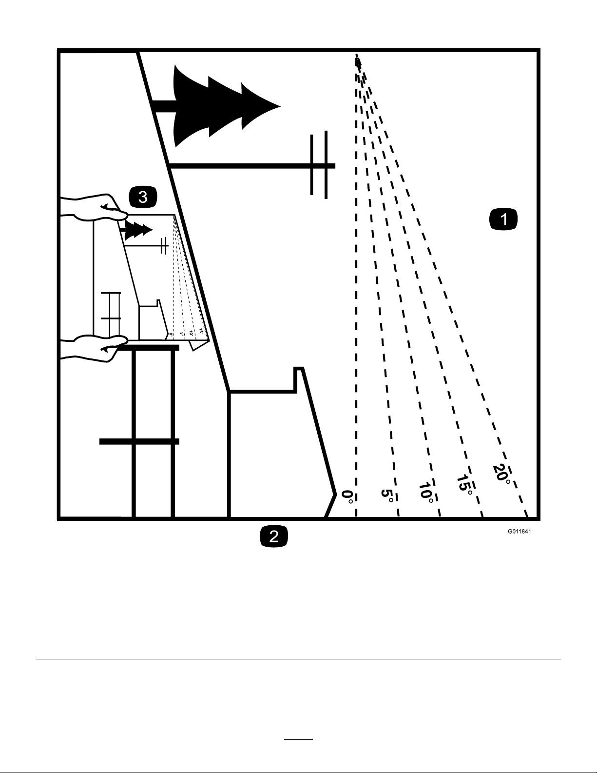
SlopeIndicator
G011841
Figure4
Thispagemaybecopiedforpersonaluse.
1.Themaximumslopeyoucansafelyoperatethemachineonis15degrees.Usetheslopecharttodeterminethedegreeofslope
ofhillsbeforeoperating.Donotoperatethismachineonaslopegreaterthan15degrees.Foldalongtheappropriateline
tomatchtherecommendedslope.
2.Alignthisedgewithaverticalsurface,atree,building,fencepole,etc.
3.Exampleofhowtocompareslopewithfoldededge
5
g011841
Page 6
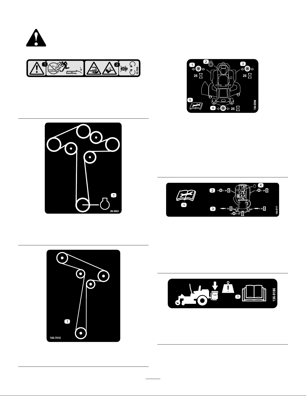
SafetyandInstructionalDecals
Safetydecalsandinstructionsareeasilyvisibletotheoperatorandarelocatednearanyareaofpotential
danger.Replaceanydecalthatisdamagedormissing.
93-7009
1.Warning—donotoperatethemowerwiththedeectorup
orremoved;keepthedeectorinplace.
2.Cutting/dismembermenthazardofhandorfoot,mower
blade—stayawayfrommovingparts.
decal93-7009
decal136-5596
136-5596
ForModelswith60-inchDecks
99-3943
ForModelswith50-inch,54-inch,or60-inchMowerDecks
1.Engine
1.Checkthetirepressure
every25operatinghours.
2.Engineoil
3.Checkthetirepressure
every25operatinghours.
decal99-3943
4.Checkthetirepressure
every25operatinghours.
5.ReadtheOperator's
Manualbeforeperforming
maintenance.
decal106-8717
106-8717
ForModelswith42-inch,50-inch,or54-inchMowerDecks
1.Readtheinstructionsbeforeservicingorperforming
maintenance.
2.Checktirepressureevery25operatinghours.
3.Greaseevery25operatinghours.
4.Engine
105-7015
ForModelswith42-inchDecks
decal136-9186
136-9186
ForMachineswitha60-inchDeckOnly
1.ReadtheOperator'sManualbeforeaddingweighttothe
bucket.
decal105-7015
6
Page 7
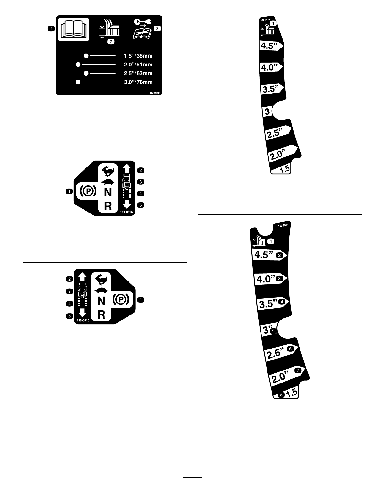
decal112-9840
112-9840
1.ReadtheOperator's
Manual.
2.Heightofcut
119-8814
1.Parkingposition4.Neutral
2.Fast5.Reverse
3.Slow
3.Removetheignitionkey
andreadtheinstructions
beforeservicingor
performingmaintenance.
decal119-8870
119-8870
ForModelswith50-inch,54-inch,or60-inchMowerDecks
1.Heightofcut
decal119-8814
119-8815
1.Parkingposition4.Neutral
2.Fast5.Reverse
3.Slow
decal119-8815
decal119-8871
119-8871
ForModelswith42-inchMowerDecks
1.Heightofcut
7
Page 8
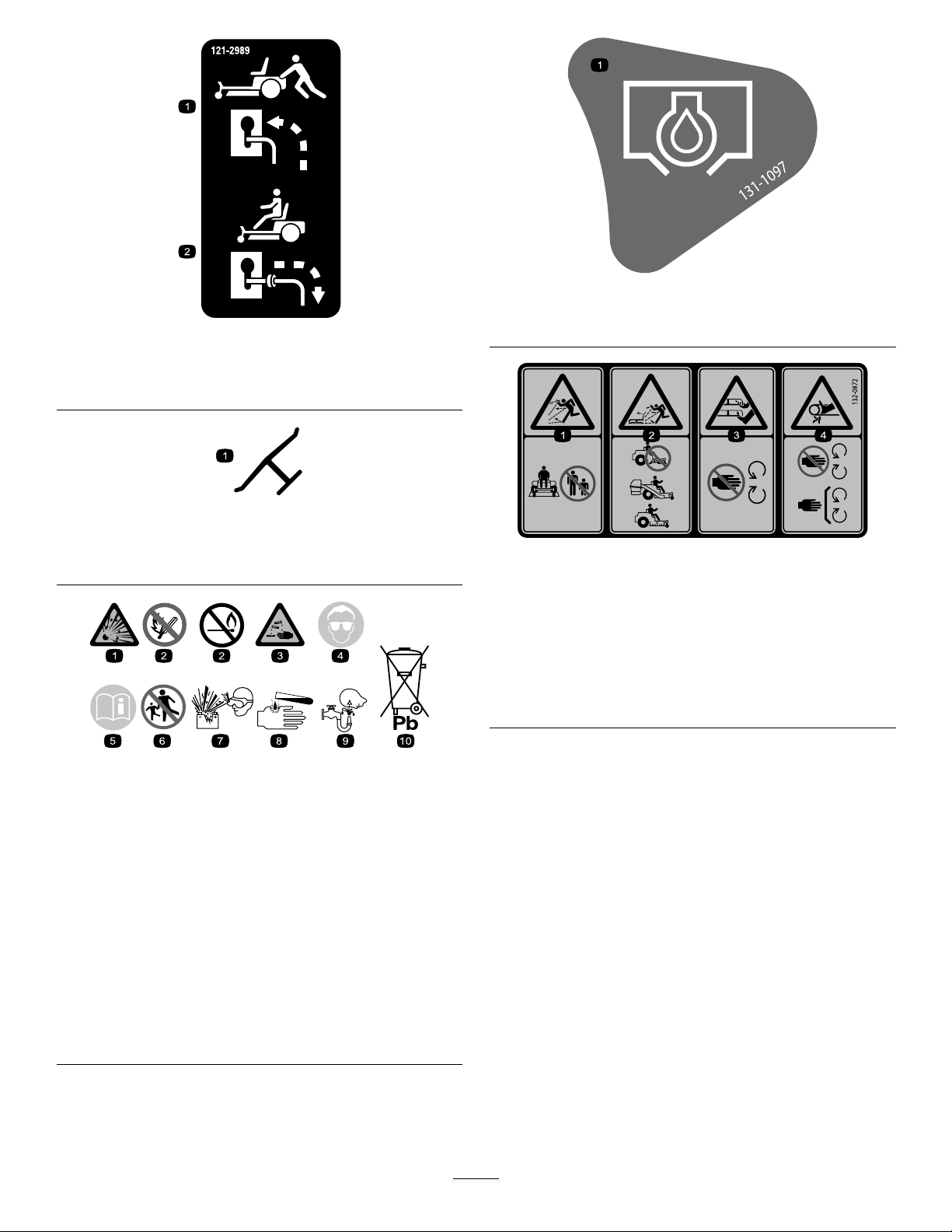
decal131-1097
131-1097
121-2989
1.Bypassleverpositionfor
pushingthemachine
2.Bypassleverpositionfor
operatingthemachine
Manufacturer'sMark
1.Indicatesthebladeisidentiedasapartfromtheoriginal
machinemanufacturer.
BatterySymbols
Someorallofthesesymbolsareonyourbattery .
decal121-2989b
decaloemmarkt
1.Oildrain
decal132-0872
132-0872
1.Thrownobject
hazard—keepbystanders
awayfromthemachine.
2.Thrownobjecthazard,
raisedbafe—donot
operatethemachinewith
anopendeck;usea
baggerorabafe.
decalbatterysymbols
3.Severinghazardofhand
orfoot—keepawayfrom
movingparts.
4.Entanglement
hazard—keepaway
frommovingparts;keep
allguardsandshieldsin
place.
1.Explosionhazard
2.Nore,opename,or
6.Keepbystandersasafe
7.Weareyeprotection;
smoking
3.Causticliquid/chemical
8.Batteryacidcancause
burnhazard
4.Weareyeprotection.9.Flusheyesimmediately
5.ReadtheOperator's
10.Containslead;donot
Manual.
distanceawayfromthe
battery.
explosivegasescan
causeblindnessandother
injuries.
blindnessorsevereburns.
withwaterandgetmedical
helpfast.
discard.
8
Page 9
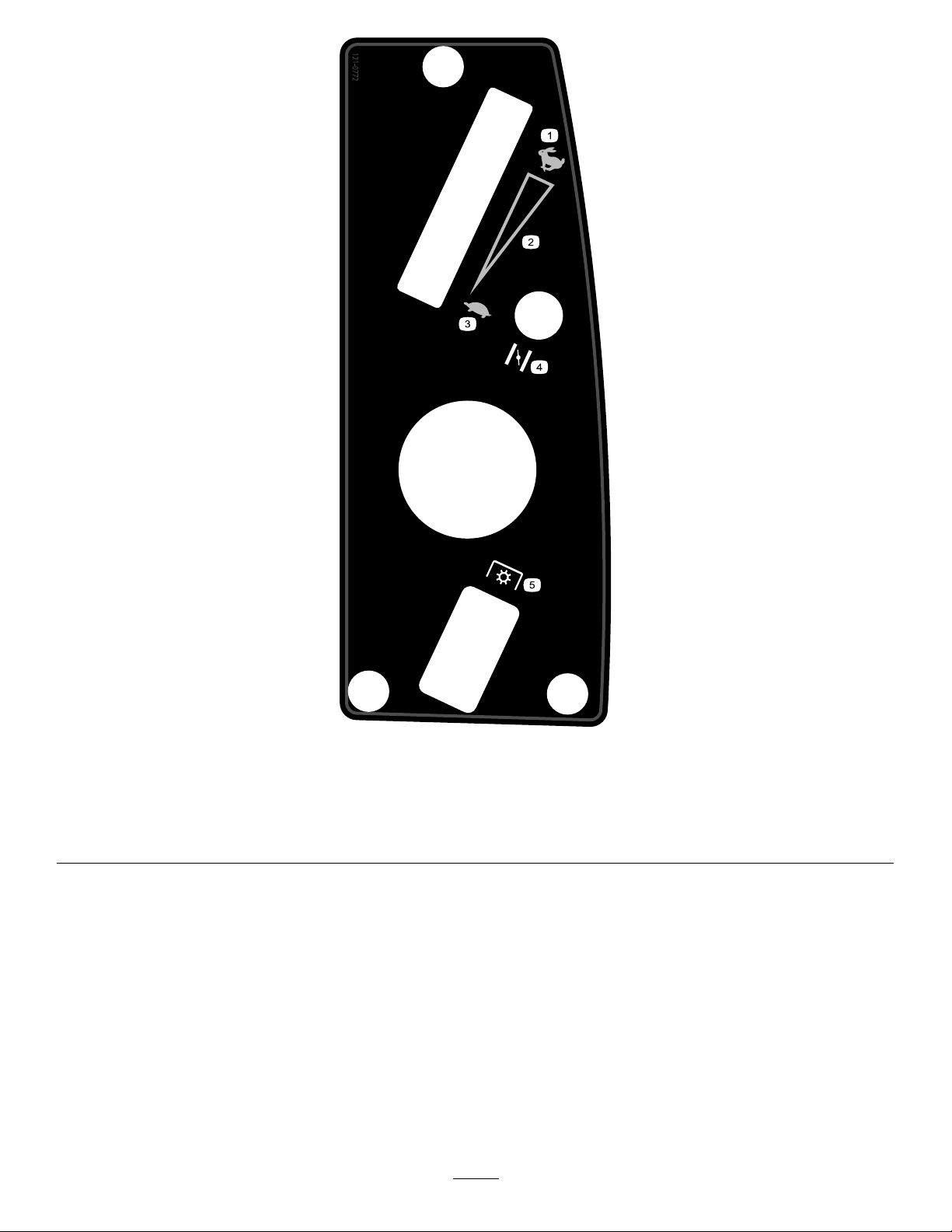
121-0772
ForModelswith42-inch,50-inch,or60-inchMowerDecks
decal121-0772
1.Fast
4.Choke
2.Continuous-variablesetting5.Powertakeoff(PTO),Blade-controlswitch
3.Slow
9
Page 10
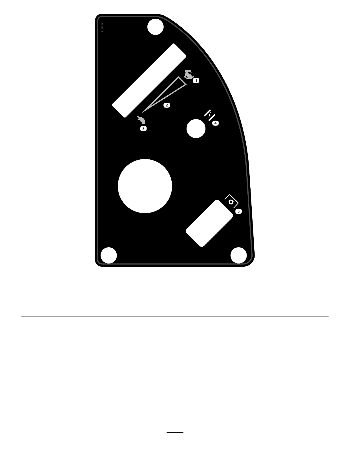
121-0773
Modelswith54-inchMowerDeck
decal121-0773
1.Fast
4.Choke
2.Continuous-variablesetting5.Powertake-off(PTO),blade-controlswitch
3.Slow
10
Page 11

decal131-3947
131-3947
1.Trim—slow
3.Mow—fast
2.Tow—medium
11
Page 12
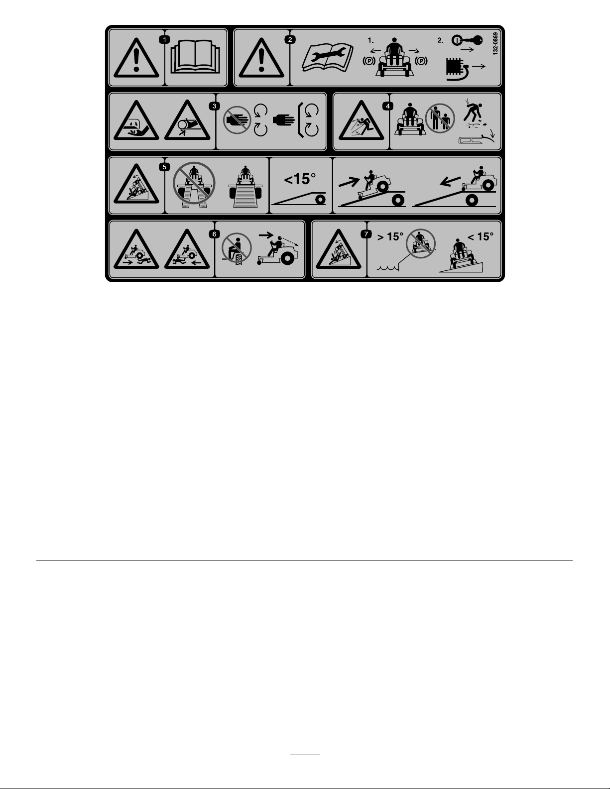
132-0869
ForModelswith42-inch,50-inch,or54-inchMowerDecks—Thismachinecomplieswiththeindustrystandardstability
testinthestaticlateralandlongitudinaltestswiththemaximumrecommendedslopeindicatedonthedecal.Reviewthe
instructionsforoperatingthemachineonslopesintheOperator'sManualandtheconditionsinwhichthemachineisbeing
operatedtodeterminewhetherthemachinecanbeoperatedintheconditionsonthatdayandatthatsite.Changesinthe
terraincanresultinachangeinslopeoperationforthemachine.Ifpossible,keepthecuttingunitsloweredtotheground
whileoperatingthemachineonslopes.Raisingthecuttingunitswhileoperatingonslopescancausethemachineto
becomeunstable.
decal132-0869
1.Warning—readthe
Operator'sManual.
2.Warning—beforeservicing,
engagetheparkingbrake,
removethekeyandthe
sparkplugconnection.
3.Cuttinghazardofhand,
mowerblade;pinching
hazardofhand,belt—keep
handsandfeetawayfrom
movingparts;keepall
guardsandshieldsinplace.
4.Thrownobject
hazard—keepbystanders
awayfromthemachine;
removedebrisfromthe
areabeforemowing;keep
thedeectorshielddown.
5.Ramptipping
hazard—whenloading
ontoatrailer,donotuse
dualramps;onlyusea
singlerampwideenough
forthemachineandthat
hasaninclinelessthan
15degrees;backupthe
ramp(inreverse)anddrive
forwardofftheramp.
6.Bodilyharmhazard—no
riders;lookbehindyou
whenmowinginreverse.
7.Tippinghazardon
slopes—donotuseon
slopesnearopenwater;do
notuseonslopesgreater
than15degrees.
12
Page 13
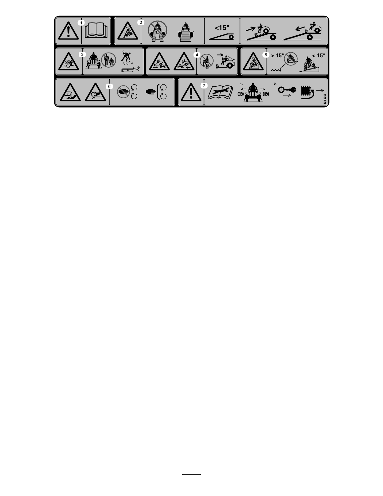
decal133-9255
133-9255
Modelswith60-inchMowerDeck—Thismachinecomplieswiththeindustrystandardstabilitytestinthestaticlateraland
longitudinaltestswiththemaximumrecommendedslopeindicatedonthedecal.Reviewtheinstructionsforoperating
themachineonslopesintheOperator'sManualandtheconditionsinwhichthemachineisbeingoperatedtodetermine
whetherthemachinecanbeoperatedintheconditionsonthatdayandatthatsite.Changesintheterraincanresultina
changeinslopeoperationforthemachine.Ifpossible,keepthecuttingunitsloweredtothegroundwhileoperatingthe
machineonslopes.Raisingthecuttingunitswhileoperatingonslopescancausethemachinetobecomeunstable.
1.Warning—readtheOperator'sManual.
2.Ramphazard—donotusedualrampswhenloadingontoa
trailer;use1rampwideenoughforthemachine;usearamp
withaslopelessthan15°;backuptherampwhenloadingthe
machineanddriveforwardofftherampwhenunloading.
3.Thrownobjecthazard—keepbystandersasafedistancefrom
themachine,pickupdebrisbeforeoperating,andkeepthe
deectorshielddown.
4.Bodilyharmhazard—donotcarrypassengers;lookbehind
youwhenmowinginreverse.
5.Tippinghazard—donotuseonslopesnearopenwater;do
notuseonslopesgreaterthan15°.
6.Cuttingandpinchhazard—keepawayfrommovingparts;
keepallguardsandshieldsinplace.
7.Warning—beforeperformingmaintenance,readthe
Operator'sManual;engagetheparkingbrake,removethe
ignitionkey,anddisconnectthesparkplug.
13
Page 14

ProductOverview
g028166
9
2
1
5 3
4
7
2
10
8
6
11
12
g028166
Figure5
1.Deector4.Height-of-cutlever
2.Reardrivewheel
3.Motion-controllevers
5.Operatorseat
6.SmartSpeed™lever9.Controlpanel
Controls
BecomefamiliarwithallofthecontrolsinFigure5and
Figure6beforeyoustarttheengineandoperatethemachine.
7.Footrest10.Engine
8.Fuel-tankcap11.Engineguard
12.Frontcasterwheel
IgnitionSwitch
Usethisswitchtostartthemowerengine.Ithas3positions:
START,RUN,andOFF.
ChokeControl
Usethechoketostartacoldengine.Pullthechokeknob
uptoengageit.Pushthechokeknobdowntodisengage
it(Figure6).
ThrottleControl
Thethrottlecontrolstheenginespeed,andithasa
continuous-variablesettingfromtheSLOWtoFASTposition
(Figure6).
g032603
Figure6
Controlpanel
1.Throttle3.Blade-controlswitch
2.Choke
4.Ignitionswitch
(powertakeoff)
Blade-ControlSwitch(PowerTakeoff)
Theblade-controlswitch,representedbyapower-takeoff
(PTO)symbol,engagesanddisengagespowertothemower
blades(Figure6).
14
Page 15
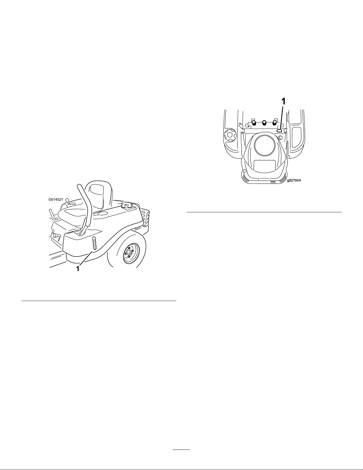
Motion-ControlLevers
G014521
1
g027869g027
1
Height-of-CutLever
Usethemotion-controlleverstodrivethemachineforward,
reverse,andturneitherdirection.
ParkPosition
Movethemotion-controlleversoutwardfromthecenterto
thePARKpositionwhenexitingthemachine(Figure21).
Alwayspositionthemotion-controlleversintothePARK
positionwhenyoustopthemachineorleaveitunattended.
SmartSpeed™ControlSystemLever
TheSmartSpeed™Control-Systemlever,locatedbelowthe
operatingposition,givesyouachoicetodrivethemachineat
3speedranges—trim,tow ,andmow(Figure24).
Fuel-PresenceWindow
Youcanusethefuelwindow ,locatedontheleftsideofthe
machine,toverifythepresenceoffuelinthetank(Figure7).
Theheight-of-cutleverworkswiththefootpedaltolockthe
deckinaspeciccuttingheight.Adjusttheheightofcutonly
whenthemachineisnotmoving(Figure5).
HourMeter
Thehourmeterrecordsthenumberofhourswhenyou
areintheseatandtheignitionswitchisintheONposition
(Figure8).
g027869
Figure8
1.Fuel-presencewindow
Figure7
1.Hourmeterlocationbehindtheseat
Attachments/Accessories
AselectionofToroapprovedattachmentsandaccessoriesis
availableforusewiththemachinetoenhanceandexpand
itscapabilities.ContactyourAuthorizedServiceDealeror
Distributororgotowww .Toro.comforalistofallapproved
g014521
attachmentsandaccessories.
15
Page 16

Operation
thenrefuelfromaportablecontainerratherthana
fuel-dispensernozzle.
Note:Determinetheleftandrightsidesofthemachine
fromthenormaloperatingposition.
BeforeOperation
BeforeOperationSafety
GeneralSafety
•Neverallowchildrenoruntrainedpeopletooperateor
servicethemachine.Localregulationsmayrestrictthe
ageoftheoperator.Theownerisresponsiblefortraining
alloperatorsandmechanics.
•Becomefamiliarwiththesafeoperationoftheequipment,
operatorcontrols,andsafetysigns.
•Knowhowtostopthemachineandshutofftheengine
quickly.
•Checkthatoperator-presencecontrols,safetyswitches,
andshieldsareattachedandfunctioningproperly.Donot
operatethemachineunlesstheyarefunctioningproperly.
•Beforemowing,alwaysinspectthemachinetoensurethat
theblades,bladebolts,andcuttingassembliesareingood
workingcondition.Replacewornordamagedbladesand
boltsinsetstopreservebalance.
•Inspecttheareawhereyouwillusethemachineand
removeallobjectsthatthemachinecouldthrow.
•Evaluatetheterraintodeterminetheappropriate
equipmentandanyattachmentsoraccessoriesrequiredto
operatethemachineproperlyandsafely.
FuelSafety
•Toavoidpersonalinjuryorpropertydamage,useextreme
careinhandlingfuel.Fuelvaporsareammableand
explosive.
•Extinguishallcigarettes,cigars,pipes,andothersources
ofignition.
•Donotoperatethemachinewithouttheentireexhaust
systeminplaceandinproperworkingcondition.
•Keepthefuel-dispensernozzleincontactwiththerimof
thefueltankorcontaineropeningatalltimesuntilfueling
iscomplete.Donotuseanozzlelock-opendevice.
•Ifyouspillfuelonyourclothing,changeyourclothing
immediately.Wipeupanyfuelthatspills.
•Neveroverllthefueltank.Replacethefuelcapand
tightenitsecurely.
•Storefuelinanapprovedcontainerandkeepitoutofthe
reachofchildren.Neverbuymorethana30-daysupply
offuel.
•Donotllthefueltankcompletelyfull.Addfueltothe
fueltankuntilthelevelis6to13mm(1/4to1/2inch)
belowthebottomofthellerneck.Thisemptyspacein
thetankallowsfueltoexpand.
–Avoidprolongedbreathingofvapors.
–Keepyourfaceawayfromthenozzleandfueltank
opening.
–Avoidcontactwithskin;washoffspillswithsoapand
water.
RecommendedFuel
•Forbestresults,useonlyclean,fresh(lessthan30days
old),unleadedgasolinewithanoctaneratingof87or
higher((R+M)/2ratingmethod).
•Ethanol:Gasolinewithupto10%ethanol(gasohol)
or15%MTBE(methyltertiarybutylether)byvolume
isacceptable.EthanolandMTBEarenotthesame.
Gasolinewith15%ethanol(E15)byvolumeisnot
approvedforuse.Neverusegasolinethatcontains
morethan10%ethanolbyvolume,suchasE15
(contains15%ethanol),E20(contains20%ethanol),or
E85(containsupto85%ethanol).Usingunapproved
gasolinemaycauseperformanceproblemsand/orengine
damagewhichmaynotbecoveredunderwarranty.
•Useonlyanapprovedfuelcontainer.
•Donotremovethefuelcaporaddfueltothefueltank
whiletheengineisrunningorwhilehot.
•Donotrefuelthemachineindoors.
•Donotstorethemachineorfuelcontainerwherethere
isanopename,spark,orpilotlight,suchasonawater
heateroronotherappliances.
•Donotllcontainersinsideavehicleoronatruckor
trailerbedwithaplasticliner.Alwaysplacecontainerson
theground,awayfromyourvehiclebeforelling.
•Removetheequipmentfromthetruckortrailerand
refuelitwhileitisontheground.Ifthisisnotpossible,
•Donotusegasolinecontainingmethanol.
•Donotstorefueleitherinthefueltankorfuelcontainers
overthewinterunlessyouuseafuelstabilizer.
•Donotaddoiltogasoline.
16
Page 17
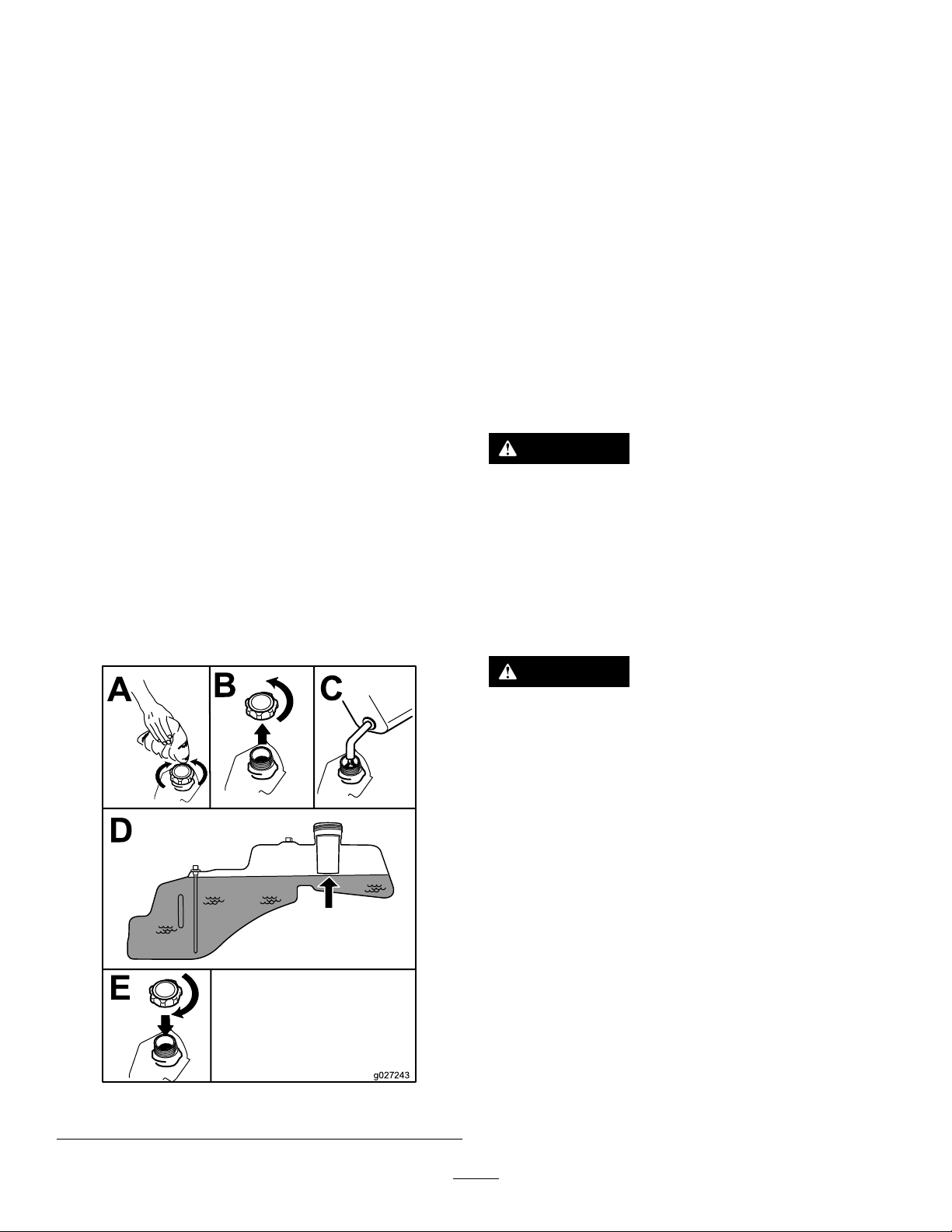
UsingStabilizer/Conditioner
g027243
A
B
E
D
C
CheckingtheEngine-OilLevel
Useafuelstabilizer/conditionerinthemachinetoprovide
thefollowingbenets:
•Keepsfuelfreshduringstorageof90daysorless(drain
thefueltankwhenstoringthemachineformorethan
90days)
•Cleanstheenginewhileitruns
•Eliminatesgum-likevarnishbuildupinthefuelsystem,
whichcauseshardstarting
Important:Donotusefueladditivescontaining
methanolorethanol.
Addthecorrectamountoffuelstabilizer/conditioner
tothefuel.
Note:Afuelstabilizer/conditionerismosteffective
whenmixedwithfreshfuel.T ominimizethechanceof
varnishdepositsinthefuelsystem,usefuelstabilizerat
alltimes.
FillingtheFuelTank
1.Parkthemachineonalevelsurface.
2.Engagetheparkingbrake.
3.Shutofftheengineandremovethekey.
4.Cleanaroundthefuel-tankcap.
5.Fillthefueltanktothebottomofthellerneck(Figure
9).
Note:Donotllthefueltankcompletelyfull.The
emptyspaceinthetankallowsthefueltoexpand.
Beforeyoustarttheengineandusethemachine,check
theoillevelintheenginecrankcase;refertoCheckingthe
Engine-OilLevel(page17).
BreakinginaNewMachine
Newenginestaketimetodevelopfullpower.Mowerdecks
anddrivesystemshavehigherfrictionwhennew,placing
additionalloadontheengine.Allow40to50hoursof
break-intimefornewmachinestodevelopfullpowerand
bestperformance.
ThinkSafetyFirst
Pleasereadallsafetyinstructionsandsymbolsinthesafety
section.Knowingthisinformationcouldhelpyouor
bystandersavoidinjury.
DANGER
Operatingthemachineonwetgrassorsteepslopes
cancauseslidingandlossofcontrol.
•Donotoperateonslopesgreaterthan15degrees.
•Reducespeedanduseextremecautionon
slopes.
•Donotoperatethemachinenearwater.
DANGER
Wheelsdroppingoveredgescancauserollovers,
whichmayresultinseriousinjury,death,or
drowning.
Donotoperatethemachineneardrop-offs.
g027243
Figure9
17
Page 18
G009027
1
2
UsingtheSafety-Interlock System
WARNING
Ifthesafety-interlockswitchesaredisconnectedor
damaged,themachinecouldoperateunexpectedly,
causingpersonalinjury.
•Donottamperwiththeinterlockswitches.
•Checktheoperationoftheinterlockswitches
dailyandreplaceanydamagedswitchesbefore
operatingthemachine.
Figure10
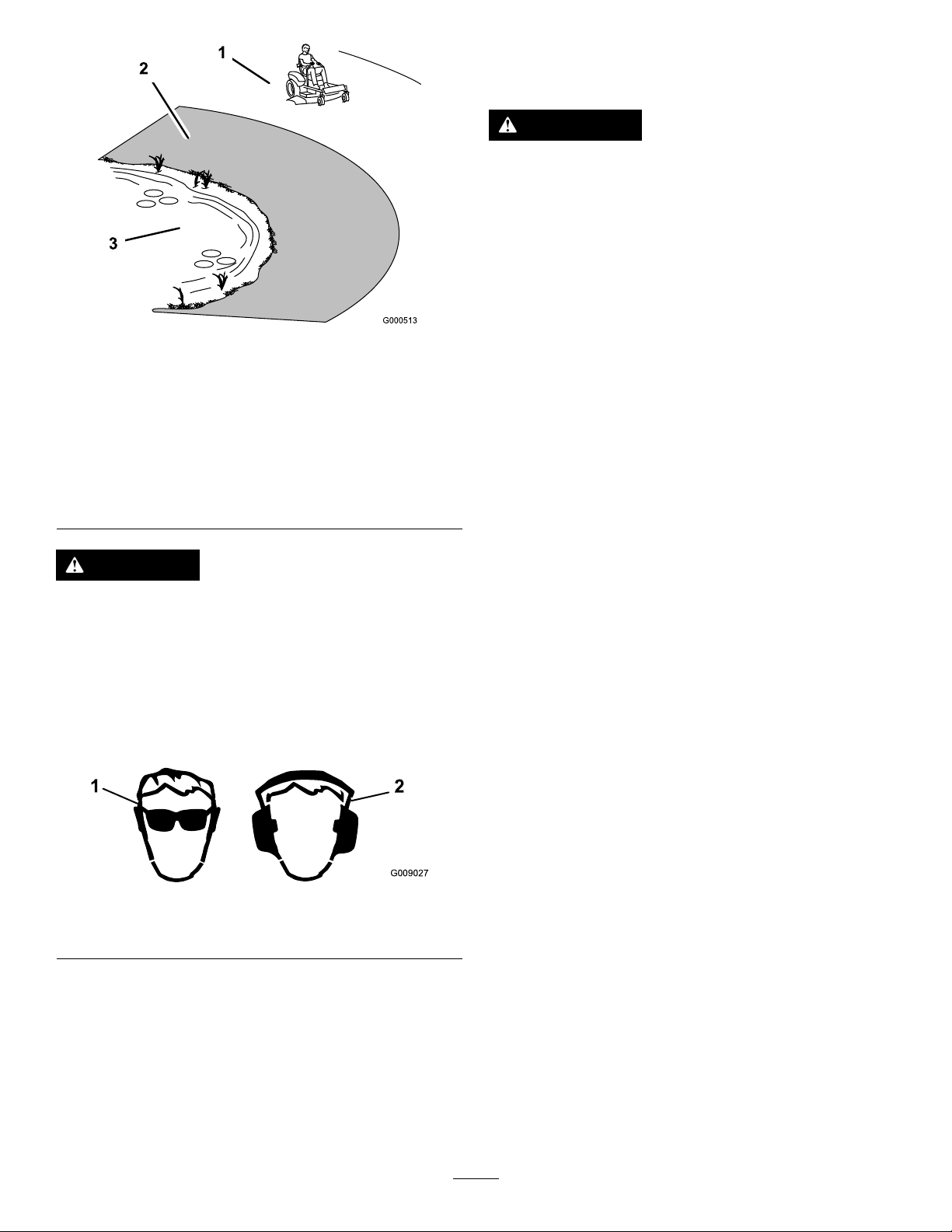
1.SafeZone—usethe
machinehereonslopes
lessthan15degreesor
atareas.
2.DangerZone—usea
walk-behindmowerand/or
ahandtrimmeronslopes
greaterthan15degrees,
neardrop-offsandwater.
3.Water
CAUTION
Thismachineproducessoundlevelsinexcessof
85dBAattheoperator’searandcancausehearing
lossthroughextendedperiodsofexposure.
Wearhearingprotectionwhenoperatingthis
machine.
Useprotectiveequipmentforyoureyes,ears,hands,feet,
andhead.
g000513
UnderstandingtheSafety-Interlock
System
Thesafety-interlocksystemisdesignedtopreventtheengine
fromstartingunless:
•Theblade-controlswitch(PTO)isdisengaged.
•Themotion-controlleversareinthePARKposition.
Thesafety-interlocksystemalsoisdesignedtoshutoffthe
enginewheneverthecontrolleversareoutofthePARK
positionandyourisefromtheseat.
TestingtheSafety-InterlockSystem
Testthesafety-interlocksystembeforeyouusethemachine
eachtime.Ifthesafetysystemdoesnotoperateasdescribed
below,haveanAuthorizedServiceDealerrepairthesafety
systemimmediately.
1.Sitontheseat,movethemotion-controlleversinthe
PARKposition,andmovetheblade-controlswitchto
theONposition.Trystartingtheengine;theengine
shouldnotcrank.
2.Sitontheseatandmovetheblade-controlswitchto
theOFFposition.Moveeithermotion-controlleverto
thecenter,unlockedposition.Trystartingtheengine;
theengineshouldnotcrank.Repeatwiththeother
motion-controllever.
g009027
Figure11
1.Weareyeprotection.2.Wearhearingprotection.
3.Sitontheseat,movetheblade-controlswitchtothe
OFFposition,andlockthemotion-controlleversin
thePARKposition.Starttheengine.Whiletheengine
isrunning,engagetheblade-controlswitch,andrise
slightlyfromtheseat;theengineshouldshutoff.
4.Sitontheseat,movetheblade-controlswitchtothe
OFFposition,andlockthemotion-controlleversinthe
PARKposition.Starttheengine.Whiletheengineis
running,movethemotion-controlleverstothecenter,
unlockedposition,engagetheblade-controlswitch,and
riseslightlyfromtheseat;theengineshouldshutoff.
18
Page 19
PositioningtheSeat
g027252
B
A
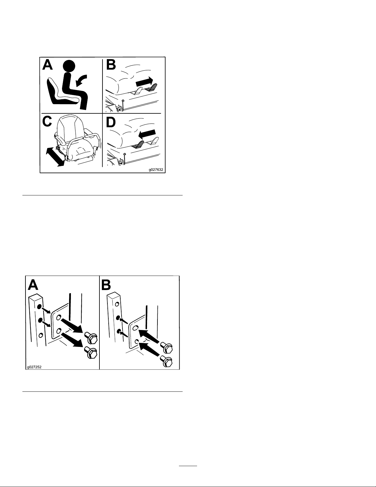
Theseatcanmoveforwardandbackward.Positiontheseat
whereyouhavethebestcontrolofthemachineandaremost
comfortable(Figure12).
Figure12
AdjustingtheTilt
Youcanadjustthemotion-controlleversforwardorrearward
foryourcomfort.
1.Loosentheupperboltholdingthecontrollevertothe
control-armshaft.
2.Loosenthelowerboltjustenoughtopivotthecontrol
leverforwardorrearward(Figure13).
3.Tightenbothboltstosecurethecontrolleverinthe
newposition.
4.Repeattheadjustmentfortheothercontrollever.
g027632
AdjustingtheMotion-Control Levers
AdjustingtheHeight
Youcanadjustthemotion-controllevershigherorlowerfor
maximumcomfort(Figure13).
Figure13
g027252
19
Page 20

DuringOperation
DuringOperationSafety
–Disengagethepowertake-offandlowerthe
attachments.
–Engagetheparkingbrake.
–Shutofftheengineandremovethekey .
GeneralSafety
•Theowner/operatorcanpreventandisresponsiblefor
accidentsthatmaycausepersonalinjuryorproperty
damage.
•Wearappropriateclothing,includingeyeprotection;
slip-resistant,substantialfootwear;andhearing
protection.Tiebacklonghairanddonotwearjewelry.
•Donotoperatethemachinewhileill,tired,orunderthe
inuenceofalcoholordrugs.
•Nevercarrypassengersonthemachineandkeep
bystandersandpetsawayfromthemachineduring
operation.
•Operatethemachineonlyingoodvisibilitytoavoidholes
orhiddenhazards.
•Avoidmowingonwetgrass.Reducedtractioncould
causethemachinetoslide.
•Ensurethatalldrivesareinneutral,theparkingbrake
isengaged,andyouareintheoperatingpositionbefore
youstarttheengine.
•Keepyourhandsandfeetawayfromthecuttingunits.
Keepclearofthedischargeopeningatalltimes.
•Lookbehindanddownbeforebackinguptobesureof
aclearpath.
•Usecarewhenapproachingblindcorners,shrubs,trees,
orotherobjectsthatmayobscureyourvision.
•Donotmowneardrop-offs,ditches,orembankments.
Themachinecouldsuddenlyrolloverifawheelgoes
overtheedgeoriftheedgegivesway.
•Stopthebladeswheneveryouarenotmowing.
•Stopthemachineandinspectthebladesafterstrikingan
objectorifthereisanabnormalvibrationinthemachine.
Makeallnecessaryrepairsbeforeresumingoperation.
•Slowdownandusecautionwhenmakingturnsand
crossingroadsandsidewalkswiththemachine.Always
yieldtheright-of-way.
•Disengagethedrivetothecuttingunitandshutoffthe
enginebeforeadjustingtheheightofcut(unlessyoucan
adjustitfromtheoperatingposition).
•Neverrunanengineinanareawhereexhaustgasesare
enclosed.
–Waitforallmovingpartstostop.
•Donotoperatethemachinewhenthereistheriskof
lightning.
•Donotusethemachineasatowingvehicle.
•Donotchangethegovernorspeedoroverspeedthe
engine.
•UseaccessoriesandattachmentsapprovedbyToroonly.
SlopeSafety
•Establishyourownproceduresandrulesforoperatingon
slopes.Theseproceduresmustincludesurveyingthesite
todeterminewhichslopesaresafeformachineoperation.
Alwaysusecommonsenseandgoodjudgmentwhen
performingthissurvey.
•Slopesareamajorfactorrelatedtoloss-of-controland
tip-overaccidents,whichcanresultinsevereinjuryor
death.Operatingthemachineonanysloperequiresextra
caution.
•Operatethemachineatalowerspeedwhenyouareona
slope.
•Ifyoufeeluneasyoperatingthemachineonaslope,do
notdoit.
•Watchforholes,ruts,bumps,rocks,orotherhidden
objects.Uneventerraincouldoverturnthemachine.Tall
grasscanhideobstacles.
•Choosealowgroundspeedsoyouwillnothavetostop
orshiftwhileonaslope.
•Arollovercanoccurbeforethetireslosetraction.
•Avoidoperatingthemachineonwetgrass.Tiresmay
losetraction;regardlessifthebrakesareavailableand
functioning.
•Avoidstarting,stopping,orturningthemachineona
slope.
•Keepallmovementonslopesslowandgradual.Donot
suddenlychangethespeedordirectionofthemachine.
•Donooperatethemachineneardrop-offs,ditches,
embankments,orbodiesofwater.Themachinecould
suddenlyrolloverifawheelgoesovertheedgeorthe
edgecavesin.Establishasafetyareabetweenthemachine
andanyhazard(2machinewidths).
•Neverleavearunningmachineunattended.
•Beforeleavingtheoperatingposition(includingtoempty
thecatchersortounclogthechute),dothefollowing:
–Parkthemachineonalevelsurface.
20
Page 21
OperatingtheMower
G008945
G009174
G008959
1
2
OperatingtheThrottle
Blade-ControlSwitch(PTO)
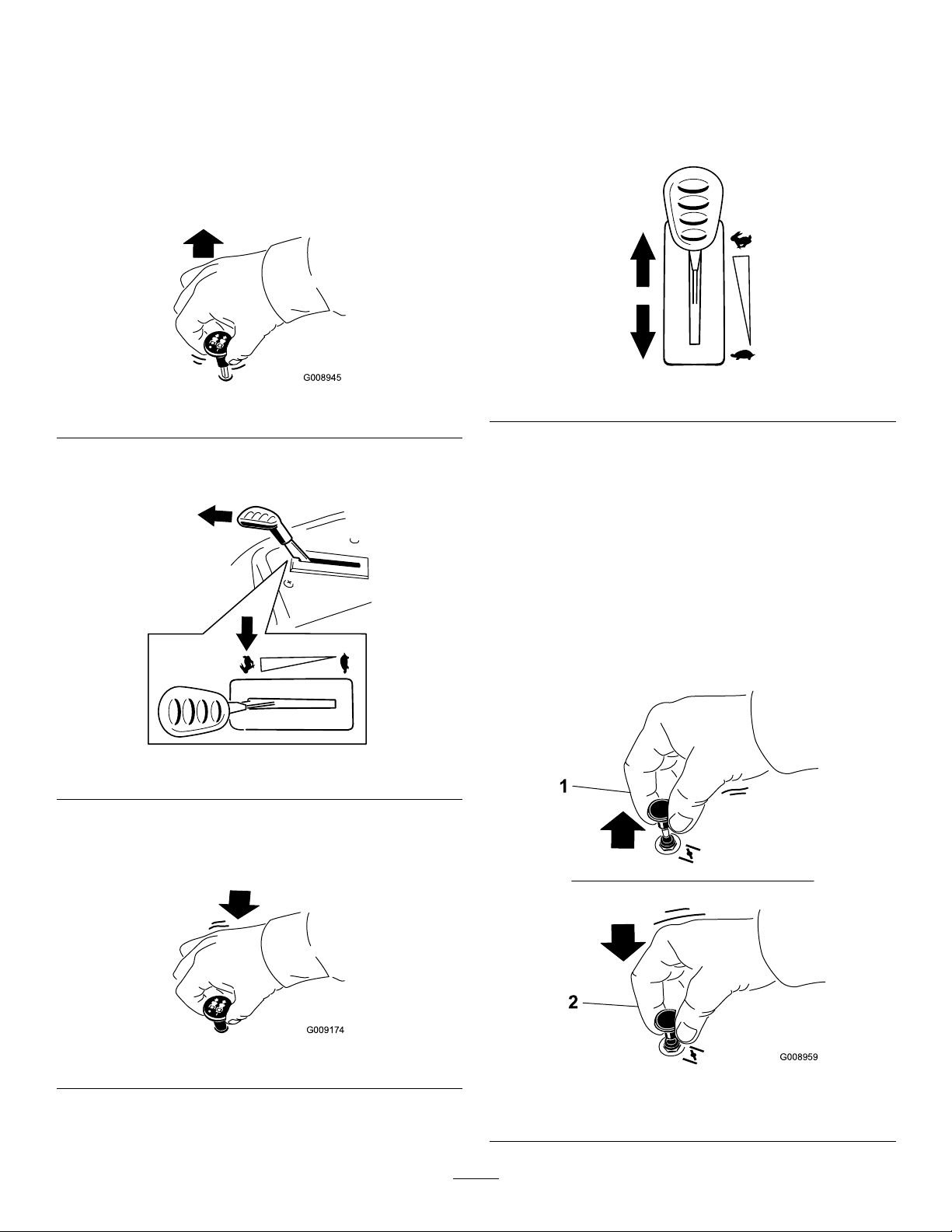
Theblade-controlswitch(PTO)startsandstopsthemower
bladesandanypoweredattachments.
EngagingtheBlade-ControlSwitch
(PTO)
Figure14
Note:AlwaysengagethebladeswiththethrottleintheFAST
position(Figure15).
YoucanmovethethrottlecontrolbetweentheFASTand
SLOWpositions(Figure17).
AlwaysusetheFASTpositionwhenturningonthemower
deckwiththeblade-controlswitch(PTO).
g187517
g008945
Figure17
OperatingtheChoke
Usethechoketostartacoldengine.
1.Iftheengineiscold,usethechoketostarttheengine.
2.Pullupthechokeknobtoengagethechokebefore
usingtheignitionswitch(Figure18).
Note:Ensurethatyoufullyengagethechoke.You
mayneedtoholdtheknobupwhenyouusethe
ignitionswitch.
3.Pushdownthechoketodisengagethechokeafterthe
enginehasstarted(Figure18).
g187516
Figure15
DisengagingtheBlade-ControlSwitch
(PTO)
g009174
Figure16
Figure18
g008959
1.Onposition2.Offposition
21
Page 22
OperatingtheIgnitionSwitch
START
RUN
STOP
G008947
g027581
B
C
D
E
A
G
F
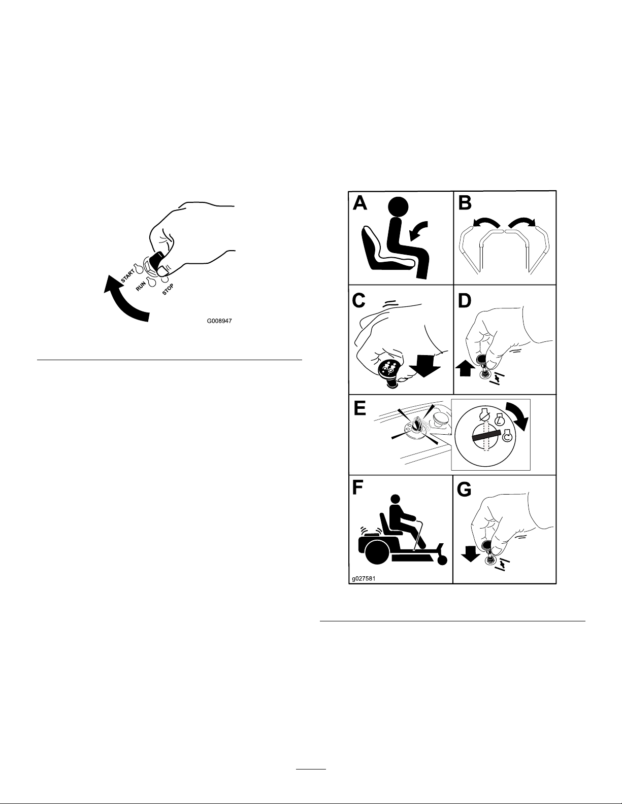
StartingandShuttingOffthe
1.TurntheignitionkeytotheSTARTposition(Figure19).
Note:Whentheenginestarts,releasethekey.
Important:Donotengagethestarterformore
than5secondsatatime.Iftheenginefailsto
start,wait15secondsbetweenattempts.Failureto
followtheseinstructionscanburnoutthestarter
motor.
Note:Youmayneedmultipleattemptstostartthe
enginewhenyoustartitthersttimeafterthefuel
systemhasbeenwithoutfuelcompletely.
Figure19
Engine
StartingtheEngine
Note:Awarmorhotenginemaynotrequirechoking.
Important:Donotengagethestarterformorethan
5secondsatatime.Engagingthestartermotorfor
morethan5secondscandamagethestartermotor.If
theenginefailstostart,wait10secondsbeforeoperating
theenginestarteragain.
g008947
2.TurntheignitionkeytotheSTOPpositiontoshutoff
theengine.
g027581
Figure20
ShuttingOfftheEngine
1.Disengagethebladesbymovingtheblade-control
switchtotheOFFposition(Figure20).
2.MovethethrottlelevertotheFASTposition.
3.TurntheignitionkeytotheOFFpositionandremove
thekey.
22
Page 23
UsingtheMotion-Control
G008952
G008953
Levers
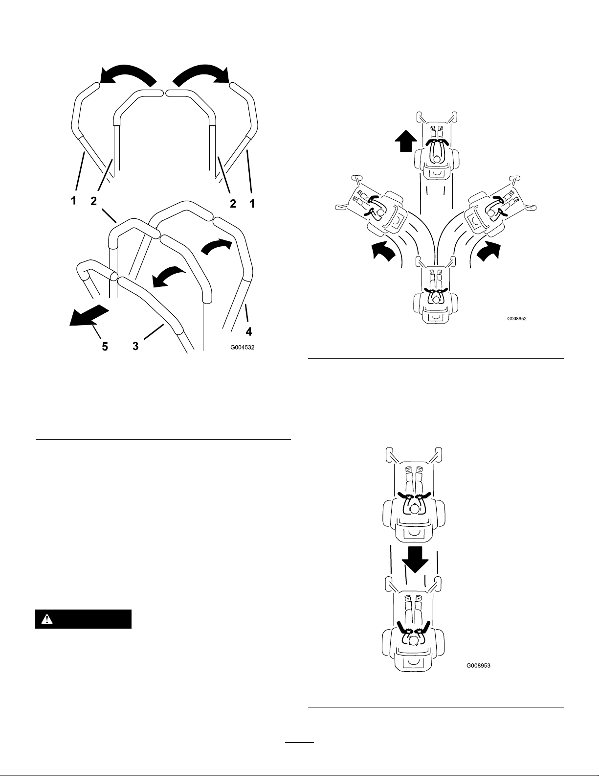
DrivingForward
Note:Alwaysusecautionwhenbackingupandturning.
1.Movetheleverstothecenter,unlockedposition.
2.Togoforward,slowlypushthemotion-controllevers
forward(Figure22).
Figure21
1.Motion-control
lever—PARKposition
2.Center,unlockedposition5.Frontofmachine
3.Forward
4.Backward
DrivingtheMachine
Thedrivewheelsturnindependently,poweredbyhydraulic
motorsoneachaxle.Youcanturn1sideinreversewhileyou
turntheotherforward,causingthemachinetospinrather
thanturn.Thisgreatlyimprovesthemachinemaneuverability
butmayrequiresometimeforyoutoadapttohowitmoves.
Thethrottlecontrolregulatestheenginespeedasmeasured
inrpm(revolutionsperminute).Placethethrottlecontrolin
theFASTpositionforbestperformance.Alwaysoperatein
thefullthrottlepositionwhenmowing.
g008952
Figure22
g004532
DrivingBackward
1.Movetheleverstothecenter,unlockedposition.
2.Togobackward,slowlypullthemotion-controllevers
rearward(Figure23).
WARNING
Themachinecanspinveryrapidly.Y oumaylose
controlofthemachineandcausepersonalinjuryor
damagetothemachine.
•Usecautionwhenmakingturns.
•Slowthemachinedownbeforemakingsharp
turns.
g008953
Figure23
23
Page 24
UsingtheSmartSpeed
TM
Control
System
TheSmartSpeed
operatingposition(Figure24),givestheoperatorachoice
todrivethemachineat3groundspeedranges—trim,tow ,
andmow .
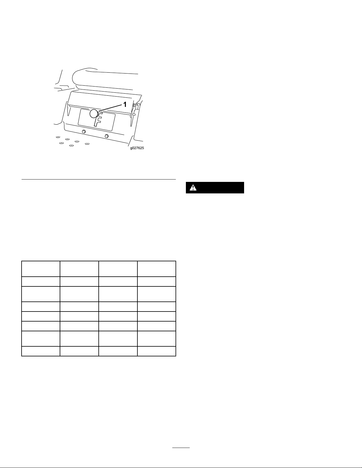
1.Smart-speedlever
TM
Control-Systemlever,locatedbelowthe
Figure24
Tow
Thisisthemediumspeed.Thesuggestedusesforthisspeed
areasfollows:
•Bagging
•Mulching
Mow
Thisisthefastestspeed.Thesuggestedusesforthisspeed
areasfollows:
•Normalmowing
•Transportingthemachine
StoppingtheMachine
Tostopthemachine,movethemotion-controlleversto
g027625
NEUTRALandoutwardtothePARKposition,disengagethe
blade-controlswitch,ensurethatthethrottleisintheFAST
position,andturntheignitionkeytoOFF.Removethekey
fromtheignitionswitch.
Tochangespeeds,dothefollowing:
1.Movethemotion-controlleverstoneutralandoutward
tothePARKposition.
2.Disengagetheblade-controlswitch.
3.Adjustthelevertothedesiredposition.
Thefollowingareonlyrecommendationsforuse.
Adjustmentsvarybygrasstype,moisturecontent,andthe
heightofthegrass.
Suggested
uses:
ParkingX
Heavy,wet
grass
TrainingX
BaggingX
MulchingX
Normal
mowing
TransportX
TrimTowMow
X
X
WARNING
Childrenorbystandersmaybeinjuredifthey
moveorattempttooperatethemowerwhileitis
unattended.
Alwaysremovetheignitionkeyandmovethe
motion-controlleversoutwardtothePARKposition
whenleavingthemachineunattended,evenifjust
forafewminutes.
Trim
Thisisthelowestspeed.Thesuggestedusesforthisspeed
areasfollows:
•Parking
•Heavy,wetgrassmowingconditions
•Training
24
Page 25
AdjustingtheHeightofCut
G010233
1
2
3
4
g024312
1
2 3 4
5
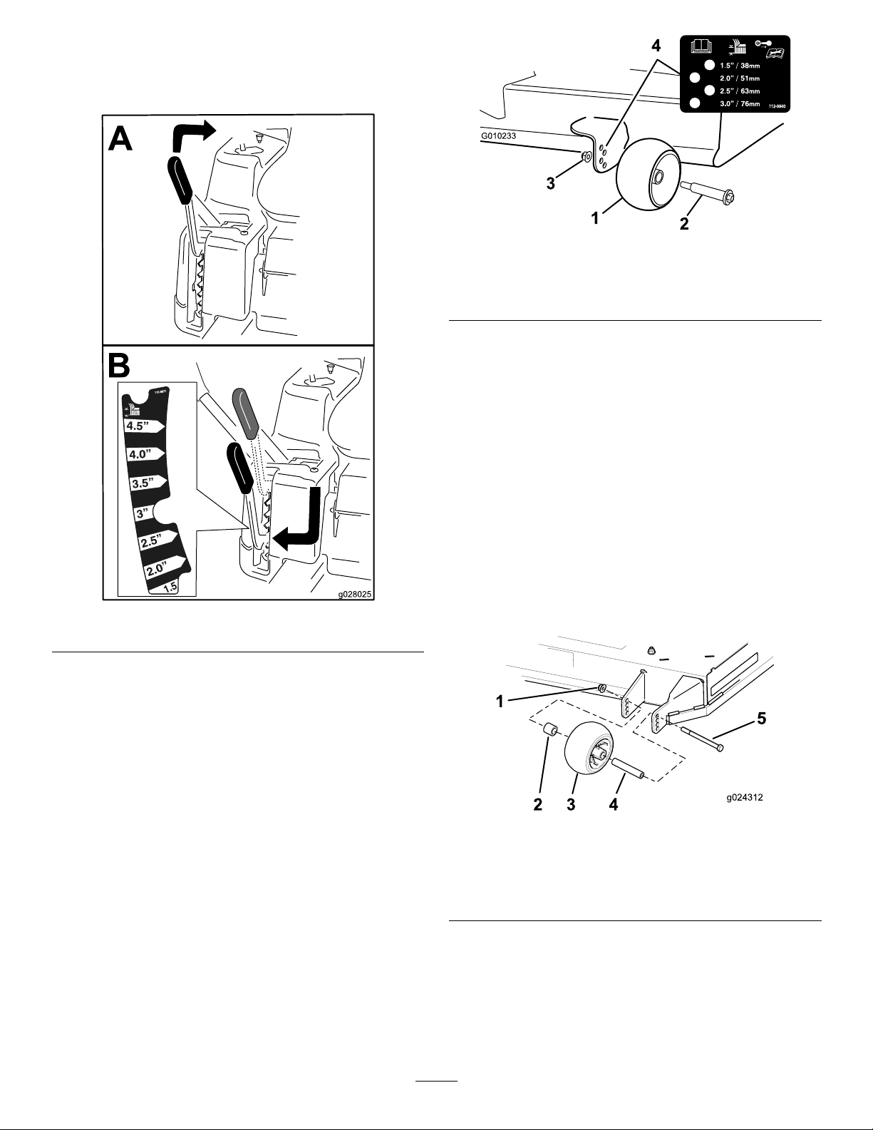
Note:Thetransportpositionisthehighestheight-of-cut
positionat115mm(4-1/2inches)asshowninFigure25.
g010233
Figure26
1.Anti-scalproller3.Flangenut
2.Bolt4.Holespacing
Machineswitha60-inchDeckOnly
Wheneveryouchangetheheightofcut,itisrecommendedto
adjusttheheightoftheanti-scalprollers.
1.Disengagetheblade-controlswitch(PTO),move
themotion-controlleverstothePARKposition,and
engagetheparkingbrake.
Figure25
AdjustingtheAnti-Scalp Rollers
Machineswitha42-inch,50-inch,or
54-inchMowerDeckOnly
Wheneveryouchangetheheightofcut,adjusttheheight
oftheanti-scalprollers.
Note:Adjusttheanti-scalprollerssothattherollersdonot
touchthegroundinnormal,atmowingareas.
1.Disengagetheblade-controlswitch(PTO),move
themotion-controlleverstothePARKposition,and
engagetheparkingbrake.
2.Shutofftheengine,removethekey ,andwaitforall
movingpartstostopbeforeleavingtheoperating
position.
3.Adjusttheanti-scalprollersasshowninFigure26to
matchtheclosestheight-of-cutposition.
2.Shutofftheengine,removethekey ,andwaitforall
movingpartstostopbeforeleavingtheoperating
position.
3.Removetheangenut,anti-scalproller,andboltfrom
thebracket(Figure27).
g028025
Note:Keeptheboltandanti-scalprollertogether
whenremoving.
Figure27
1.Flangenut4.Bushing
2.Spacer
3.Anti-scalproller
5.Bolt
g024312
4.Aligntheboltandanti-scalprollerintheholeofthe
bracketthatmatchedtheclosestheight-of-cutposition
(Figure27).
5.Inserttheboltintothebracketholeandsecurethebolt
andanti-scalprollerwiththeangenut(Figure27).
25
Page 26

UsingtheSideDischarge
Themowerhasahingedgrassdeectorthatdisperses
clippingstothesideanddowntowardtheturf.
generallythebestonetouse.Whencuttinggrasslongerthan
15cm(6inches)tall,youmaywanttocutthelawntwiceto
ensureanacceptablequalityofcut.
DANGER
Withoutagrassdeector,dischargecover,ora
completegrass-catcherassemblymountedin
place,youandothersareexposedtobladecontact
andthrowndebris.Contactwithrotatingmower
blade(s)andthrowndebriswillcauseinjuryor
death.
•Neverremovethegrassdeectorfromthemower
becausethegrassdeectorroutesmaterialdown
towardtheturf.Ifthegrassdeectorisever
damaged,replaceitimmediately .
•Neverputyourhandsorfeetunderthemower.
•Nevertrytoclearthedischargeareaormower
bladesunlessyoumovetheblade-controlswitch
(PTO)totheOFFposition,rotatetheignition
keytotheOFFposition,andremovethekey.
•Makesurethatthegrassdeectorisinthedown
position.
UsingAttachmentsand
CuttingaThirdoftheGrassBlade
Itisbesttocutonlyaboutathirdofthegrassblade.Cutting
morethanthatisnotrecommendedunlessgrassissparse,or
itislatefallwhengrassgrowsmoreslowly.
AlternatingtheMowingDirection
Alternatethemowingdirectiontokeepthegrassstanding
straight.Thisalsohelpsdisperseclippingswhichenhances
decompositionandfertilization.
MowingatCorrectIntervals
Grassgrowsatdifferentratesatdifferenttimesoftheyear.
Tomaintainthesamecuttingheight,mowmoreofteninearly
spring.Asthegrassgrowthrateslowsinmidsummer,mow
lessfrequently .Ifyoucannotmowforanextendedperiod,
rstmowatahighcuttingheight,thenmowagain2days
lateratalowerheightsetting.
UsingaSlowerCuttingSpeed
Toimprovecutquality,useaslowergroundspeedincertain
conditions.
Accessories
Machineswitha60-inchDeckOnly
UseonlyattachmentsandaccessoriesapprovedbyToro.
Ifyouattachabuckettotheengineguard,useastrapto
secureit.
Important:Ifyouarecarryingmorethan4.5kg(10lb)
inabucketattachedtotheengineguard,youshould
equipyourmachinewiththeBucketSupportKit.
ContactyourauthorizedToroservicedealer.
OperatingTips
UsingtheFastThrottleSetting
Forbestmowingandmaximumaircirculation,operatethe
engineattheFASTposition.Airisrequiredtothoroughlycut
grassclippings,sodonotsettheheight-of-cutsolowasto
totallysurroundthemowerinuncutgrass.Alwaystrytohave
1sideofthemowerfreefromuncutgrass,whichallowsair
tobedrawnintothemower.
CuttingaLawnfortheFirstTime
Cutgrassslightlylongerthannormaltoensurethatthe
cuttingheightofthemowerdoesnotscalpanyuneven
ground.However,thecuttingheightusedinthepastis
AvoidingCuttingTooLow
Whenmowinguneventurf,raisethecuttingheighttoavoid
scalpingtheturf.
StoppingtheMachine
Ifyoumuststoptheforwardmotionofthemachinewhile
mowing,aclumpofgrassclippingsmaydropontoyour
lawn.Toavoidthis,moveontoapreviouslycutareawiththe
bladesengagedoryoucandisengagethemowerdeckwhile
movingforward.
KeepingtheUndersideoftheMower
Clean
Cleanclippingsanddirtfromtheundersideofthemower
aftereachuse.Ifgrassanddirtbuildupinsidethemower,
cuttingqualitywilleventuallybecomeunsatisfactory.
MaintainingtheBlade(s)
Maintainasharpbladethroughoutthecuttingseasonbecause
asharpbladecutscleanlywithouttearingorshreddingthe
grassblades.Tearingandshreddingturnsgrassbrownat
theedges,whichslowsgrowthandincreasesthechanceof
disease.Checkthemowerbladesaftereachuseforsharpness,
andforanywearordamage.Filedownanynicksandsharpen
thebladesasnecessary.Ifabladeisdamagedorworn,replace
itimmediatelywithagenuineTororeplacementblade.
26
Page 27
AfterOperation
g017303
1 2
3
AfterOperationSafety
GeneralSafety
•Cleangrassanddebrisfromthecuttingunits,mufers,
andenginecompartmenttohelppreventres.Cleanup
oilorfuelspills.
•Shutoffthefuelbeforestoringortransportingthe
machine.
•Disengagethedrivetotheattachmentwheneveryouare
transportingornotusingthemachine.
•Usefull-widthrampsforloadingthemachineintoa
trailerortruck.
•Tiethemachinedownsecurelyusingstraps,chains,cable,
orropes.Bothfrontandrearstrapsshouldbedirected
downandoutwardfromthemachine.
•Allowtheenginetocoolbeforestoringthemachinein
anyenclosure.
•Neverstorethemachineorfuelcontainerwherethereis
anopename,spark,orpilotlight,suchasonawater
heateroronotherappliances.
PushingtheMachinebyHand
Important:Alwayspushthemachinebyhand.Donot
towthemachine,becausedamagetothehydraulicdrive
systemmayoccur.
Thismachinehasanelectric-brakemechanism.Topushthe
machine,turntheignitionkeytotheRUNposition.The
batterymustbechargedandfunctioningtodisengagethe
electricbrake.
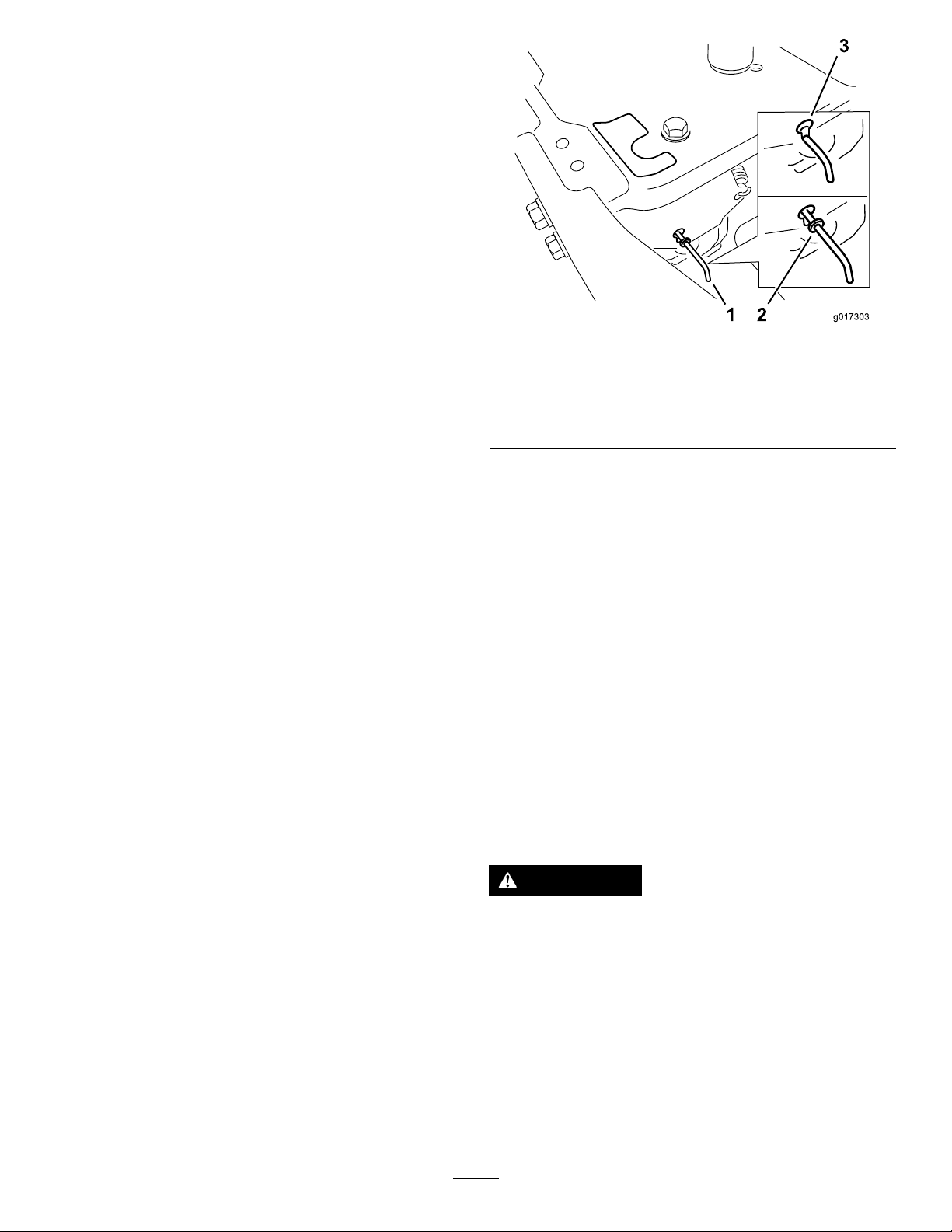
Figure28
1.Bypass-leverlocations
2.Leverpositionfor
operatingthemachine
6.Whennished,turnthekeytotheSTOPpositionto
avoiddrainingthebatterycharge.
Note:Ifthemachinefailstomove,theelectricbrake
maystillbeengaged.Youcanreleasetheelectricbrakeif
necessary;refertoReleasingtheElectricBrake(page41).
3.Leverpositionforpushing
themachine
OperatingtheMachine
Movethebypassleversrearwardthroughthekeyholeand
downtolocktheminplaceasshowninFigure28.
Note:Dothisforeachlever.
TransportingtheMachine
g017303
PushingtheMachine
1.Parkthemachineonalevelsurfaceanddisengagethe
blade-controlswitch.
2.Movethemotion-controlleversoutwardtothePARK
position,shutofftheengine,andwaitforallmoving
partstostopbeforeleavingtheoperatingposition.
3.Locatethebypassleversontheframeonbothsidesof
theengine.
4.Movethebypassleversforwardthroughthekeyhole
anddowntolocktheminplace(Figure28).
Note:Dothisforeachlever.
5.Movethemotion-controlleversinwardtothe
NEUTRALpositionandturntheignitionkeytothe
RUNposition.
Note:Donotstartthemachine.
Note:Youcannowpushthemachinebyhand.
Useaheavy-dutytrailerortrucktotransportthemachine.
Ensurethatthetrailerortruckhasallnecessarybrakes,
lighting,andmarkingasrequiredbylaw .Pleasecarefullyread
allthesafetyinstructions.Knowingthisinformationcould
helpyou,yourfamily,pets,orbystandersavoidinjury.
WARNING
Drivingonthestreetorroadwaywithout
turnsignals,lights,reectivemarkings,ora
slow-moving-vehicleemblemisdangerousandcan
leadtoaccidents,causingpersonalinjury.
Donotdrivethemachineonapublicstreetor
roadway.
1.Ifyouareusingatrailer,connectittothetowing
vehicleandconnectthesafetychains.
2.Ifapplicable,connectthetrailerbrakes.
3.Loadthemachineontothetrailerortruck.
27
Page 28
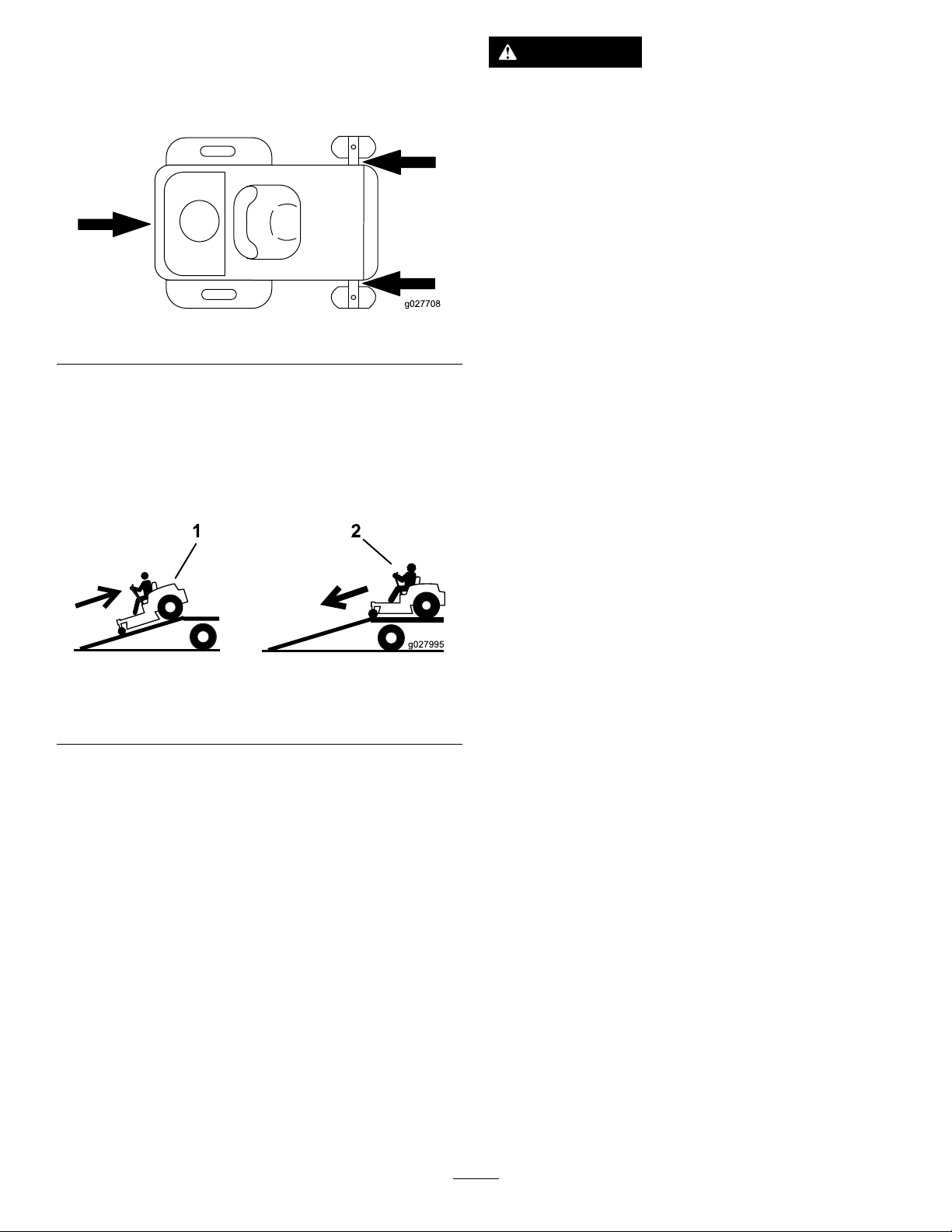
4.Shutofftheengine,removethekey,setthebrake,and
closethefuelvalve.
5.Tiedownthemachinenearthefrontcasterwheelsand
therearbumper(Figure29).
Figure29
WARNING
Loadingamachineontoatrailerortruckincreases
thepossibilityoftip-overandcouldcauseserious
injuryordeath(Figure31).
•Useextremecautionwhenoperatingamachine
onaramp.
•Useonlyafull-widthramp;donotuseindividual
rampsforeachsideofthemachine.
•Donotexceeda15-degreeanglebetweenthe
rampandthegroundorbetweentherampand
thetrailerortruck.
g027708
•Ensurethatthelengthoframpisatleast4times
aslongastheheightofthetrailerortruckbed
totheground.Thisensuresthattherampangle
doesnotexceed15degreesonatground.
LoadingtheMachine
Useextremecautionwhenloadingorunloadingmachines
ontoatraileroratruck.Useafull-widthrampthatiswider
thanthemachineforthisprocedure.Backthemachineupthe
rampanddriveitforwarddowntheramp(Figure30).
Figure30
1.Backthemachineupthe
ramp.
Important:Donotusenarrowindividualrampsfor
eachsideofthemachine.
2.Drivethemachineforward
downtheramp.
•Backuprampsanddriveforwarddownramps.
•Avoidsuddenaccelerationordecelerationwhile
drivingthemachineonarampasthiscould
causealossofcontroloratip-oversituation.
g027995
28
Page 29
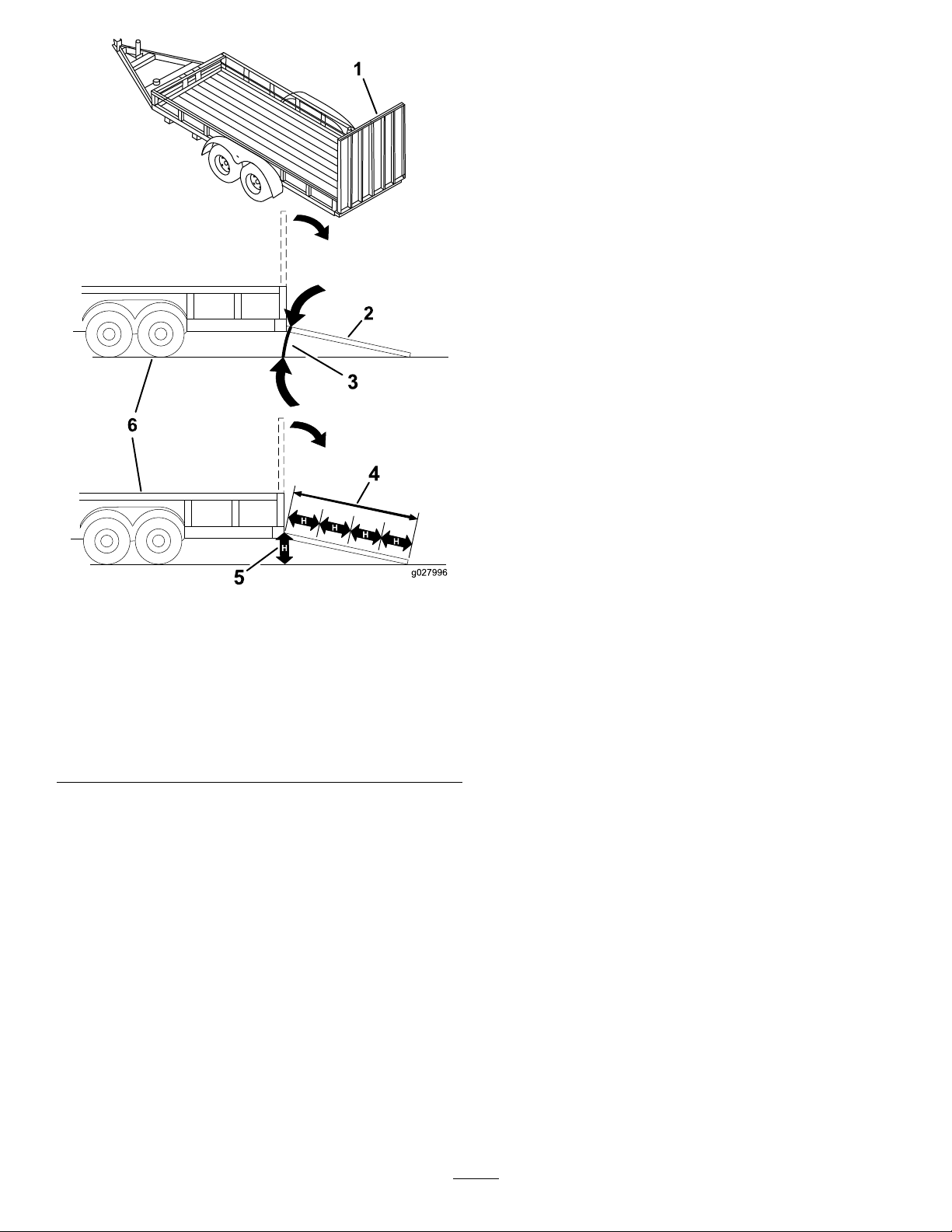
g027996
5
1
2
6
Figure31
g027996
1.Full-widthrampinstowed
position
2.Sideviewoffull-width
rampinloadingposition
3.Notgreaterthan
15degrees
4.Rampisatleast4times
aslongastheheightof
thetrailerortruckbedto
theground
5.H=heightofthetraileror
truckbedtotheground
6.Trailer
29
Page 30

Maintenance
Note:Determinetheleftandrightsidesofthemachinefromthenormaloperatingposition.
RecommendedMaintenanceSchedule(s)
MaintenanceService
Interval
Aftertherst5hours
Beforeeachuseordaily
Aftereachuse
Every25hours
Every100hours
Every200hours
MaintenanceProcedure
•Changetheengineoil.
•Checkthesafety-interlocksystem.
•Checktheaircleanerfordirty,loose,ordamagedparts.
•Checktheengine-oillevel.
•Cleantheairintakescreen.
•Inspecttheblades.
•Inspectthegrassdeectorfordamage.
•Cleanthemower-deckhousing.
•Greasealllubricationpoints(42-inchor50-inchdecksonly).
•Cleantheair-cleanerfoamelement(moreoftenindusty,dirtyconditions).
•Checktirepressure.
•Checkthebeltsforwearorcracks.
•Replacetheair-cleanerfoamelement(moreoftenindusty,dirtyconditions).
•Servicetheair-cleanerpaperelement(moreoftenindusty,dirtyconditions).
•Changetheengineoil(moreoftenindusty,dirtyconditions).
•Changetheoillter(moreoftenindusty,dirtyconditions).
•Checkthesparkplug(s).
•Checkthein-linefuellter.
•Replacetheair-cleanerpaperelement(moreoftenindusty,dirtyconditions).
•Replacethesparkplug(s).
•Replacethein-linefuellter.
•Chargethebatteryanddisconnectthebatterycables.
Beforestorage
•Performallmaintenanceprocedureslistedabovebeforestorage.
•Paintanychippedsurfaces.
CAUTION
Ifyouleavethekeyintheignitionswitch,someonecouldaccidentlystarttheengineandseriouslyinjure
youorotherbystanders.
Removethekeyfromtheignitionbeforeyouperformanymaintenance.
30
Page 31

Pre-Maintenance
RaisingtheSeat
Procedures
MaintenanceandStorage Safety
•Beforerepairingthemachinedothefollowing:
–Disengagethedrives.
–Engagetheparkingbrake.
–Shutofftheengineandremovethekey .
–Disconnectthespark-plugwire.
•Parkthemachineonalevelsurface.
•Cleangrassanddebrisfromthecuttingunit,drives,
mufers,andenginetohelppreventres.
•Cleanupoilorfuelspills.
•Lettheenginecoolbeforestoringthemachine.
•Donotstorethemachineorfuelnearamesordrain
thefuelindoors.
•Donotallowuntrainedpersonneltoservicethemachine.
Makesurethatthemotion-controlleversarelockedinthe
PARKposition.Lifttheseatforward.
Youcanaccessthefollowingcomponentsbyraisingtheseat:
•Serialplate
•Servicedecal
•Fuellter
•Batteryandbatterycables
•Usejackstandstosupportthemachineand/or
componentswhenrequired.
•Carefullyreleasepressurefromcomponentswithstored
energy.
•Disconnectthebatteryorremovethespark-plugwire
beforemakinganyrepairs.Disconnectthenegative
terminalrstandthepositiveterminallast.Connectthe
positiveterminalrstandnegativelast.
•Usecarewhencheckingtheblades.Wraptheblade(s)
orwearthicklypaddedgloves,andusecautionwhen
servicingthem.Onlyreplaceblades;donotstraighten
orweldthem.
•Keepyourhandsandfeetawayfrommovingparts.
Ifpossible,donotmakeadjustmentswiththeengine
running.
•Keepallpartsingoodworkingconditionandallhardware
tightened,especiallytheblade-attachmentbolts.Replace
allwornordamageddecals.
•Neverinterferewiththeintendedfunctionofasafety
deviceorreducetheprotectionprovidedbyasafety
device.Checktheirproperoperationregularly.
•Toensureoptimumperformanceandcontinuedsafety
certicationofthemachine,useonlygenuineToro
replacementpartsandaccessories.Replacementparts
andaccessoriesmadebyothermanufacturerscouldbe
dangerous,andsuchusecouldvoidtheproductwarranty.
•Checktheparkingbrakeoperationfrequently.Adjustand
serviceasrequired.
31
Page 32
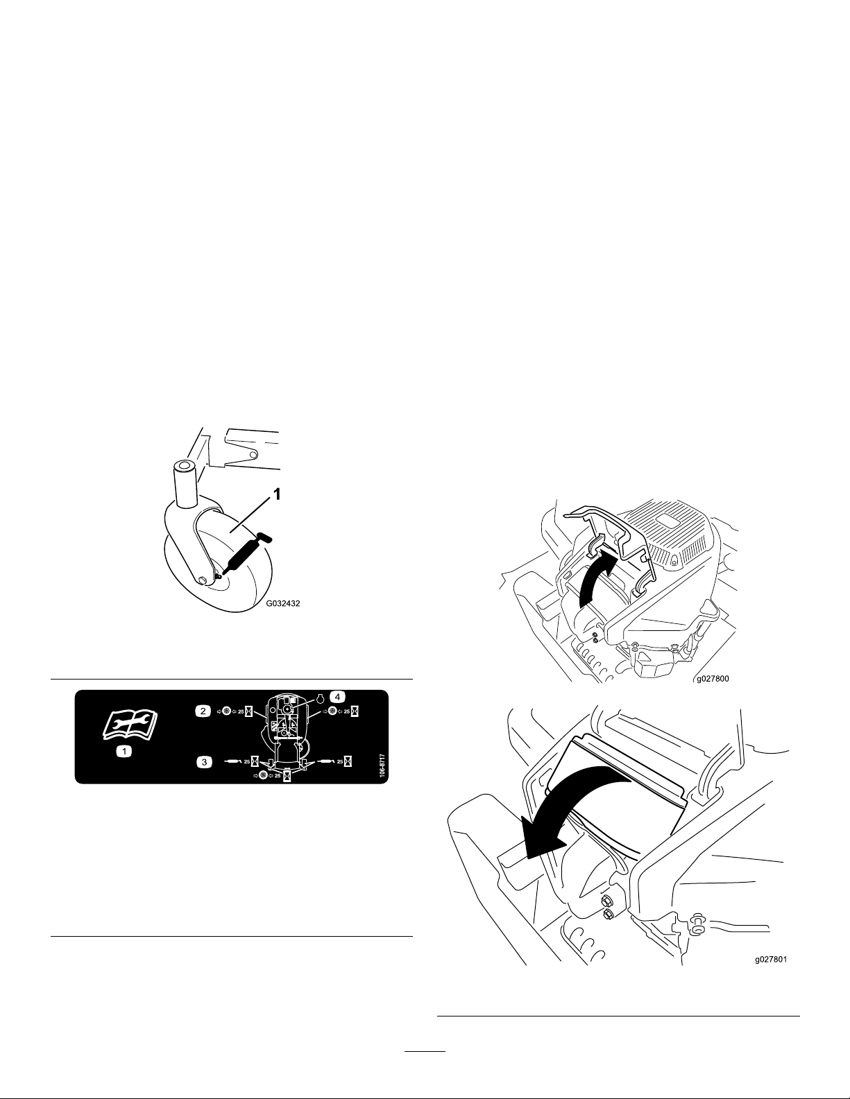
Lubrication
g027800
g027801
EngineMaintenance
GreasingtheBearings
Machineswith42-inch,50-inch,or
54-inchMowerDecksOnly
ServiceInterval:Every25hours—Greasealllubrication
points(42-inchor50-inchdecksonly).
GreaseType:No.2lithiumgrease
1.Parkthemachineonalevelsurfaceanddisengagethe
blade-controlswitch.
2.Movethemotion-controlleversoutwardtothePARK
position,shutofftheengine,removethekey,and
waitforallmovingpartstostopbeforeleavingthe
operatingposition.
3.Cleanthegreasettings(Figure32andFigure33)with
arag.
Note:Makesuretoscrapeanypaintoffthefrontof
thetting(s).
EngineSafety
Shutofftheenginebeforecheckingtheoiloraddingoilto
thecrankcase.
ServicingtheAirCleaner
ServiceInterval:Beforeeachuseordaily
Note:Servicetheaircleanermorefrequently(everyfew
hours)ifoperatingconditionsareextremelydustyorsandy.
RemovingtheElements
1.Parkthemachineonalevelsurface.
2.Disengagetheblade-controlswitch(PTO).
3.Engagetheparkingbrake.
4.Shutofftheengineandremovethekey.
5.Cleanaroundtheair-cleanercovertopreventdirtfrom
gettingintotheengineandcausingdamage.
6.Liftthecoverandrotatetheair-cleanerassemblyout
oftheengine(Figure34).
Figure32
1.Frontcastertire
Figure33
Locatedontheseat-panunderside
1.Readtheinstructions
beforeservicingor
performingmaintenance.
2.Checkthetirepressure
every25operatinghours.
3.Greaseevery25operating
hours.
4.Engine
4.Connectagreaseguntoeachtting(Figure32and
Figure33).
5.Pumpgreaseintothettingsuntilgreasebeginsto
oozeoutofthebearings.
g032432
g027800
decal106-8717
g027801
Figure34
32
Page 33
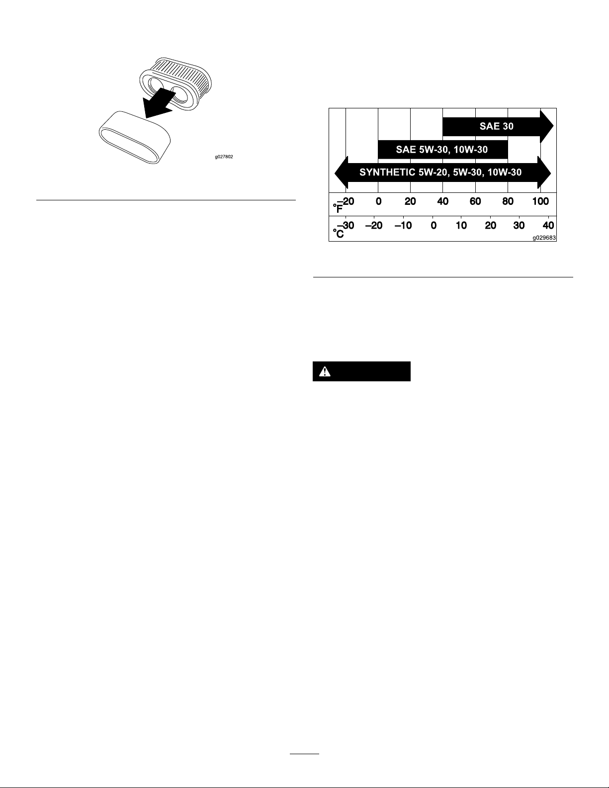
7.Removethefoamelementfromthepaperelement
g027802
SAE 5W -30, 10W -30
SAE 30
SYNTHETIC 5W -20, 5W -30, 10W -30
g029683
(Figure35).
Figure35
ServicingtheFoamElement
ServiceInterval:Every25hours/Monthly(whichever
comesrst)—Cleantheair-cleanerfoam
element(moreoftenindusty,dirty
conditions).
ServicingtheEngineOil
OilType:Detergentoil(APIserviceSF,SG,SH,SJ,orSL)
CrankcaseCapacity:withlter—2.4L(2.5USqt)
Viscosity:Seethetablebelow.
g027802
g029683
Figure36
Every100hours/Yearly(whichevercomes
rst)—Replacetheair-cleanerfoamelement(more
oftenindusty,dirtyconditions).
Washthefoamelementwithwaterandreplacethefoam
elementifitisdamaged.
ServicingthePaperElement
ServiceInterval:Every100hours/Yearly(whichevercomes
rst)—Servicetheair-cleanerpaper
element(moreoftenindusty,dirty
conditions).
Every200hours/Every2years(whichevercomes
rst)—Replacetheair-cleanerpaperelement(more
oftenindusty,dirtyconditions).
1.Lightlytaptheelementonaatsurfacetoremovedust
anddirt.
2.Inspecttheelementfortears,anoilylm,anddamage
totheseal.
Important:Donotcleanthepaperelement
withpressurizedairorliquids,suchassolvent,
gasoline,orkerosene.Replacethepaperelement
ifitisdamagedorcannotbecleanedthoroughly .
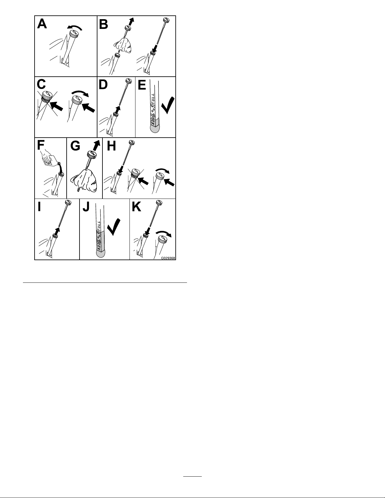
CheckingtheEngine-OilLevel
ServiceInterval:Beforeeachuseordaily
Note:Checktheoilwhentheengineiscold.
WARNING
Contactwithhotsurfacesmaycausepersonal
injury.
Keepyourhands,feet,face,clothing,andother
bodypartsawaythemuferandotherhotsurfaces.
Important:Ifyouoverllorunderlltheengine
crankcasewithoilandruntheengine,youmaydamage
theengine.
1.Parkthemachineonalevelsurface.
2.Disengagetheblade-controlswitch(PTO).
3.Engagetheparkingbrake.
4.Shutofftheengineandremovethekey.
5.Makesurethattheengineisshutoff,level,andiscool,
sothattheoilhashadtimetodrainintothesump.
6.Tokeepdirt,grassclippings,etc.,outoftheengine,
cleantheareaaroundtheoil-llcapanddipstickbefore
removingit(Figure37).
7.Shutofftheengine,removethekey ,andwaitforall
movingpartstostopbeforeleavingtheoperating
position.
33
Page 34
B
A
C
D
E
G029368
F
G H
I J K
ChangingtheEngineOilandOilFilter
ServiceInterval:Aftertherst5hours/Aftertherst
month(whichevercomesrst)—Change
theengineoil.
Every100hours/Yearly(whichevercomes
rst)—Changetheengineoil(moreoftenindusty,
dirtyconditions).
Every100hours/Yearly(whichevercomes
rst)—Changetheoillter(moreoftenindusty,dirty
conditions).
Note:Changetheengine-oilltermorefrequentlywhen
operatingconditionsareextremelydustyorsandy.
Note:Disposeoftheusedoilatarecyclingcenter.
1.Parkthemachineonalevelsurfacetoensurethatthe
oildrainscompletely.
2.DisengagethePTOandensurethattheparkingbrake
isengaged.
3.Shutofftheengine,removethekey ,andwaitforall
movingpartstostopbeforeleavingtheoperating
position.
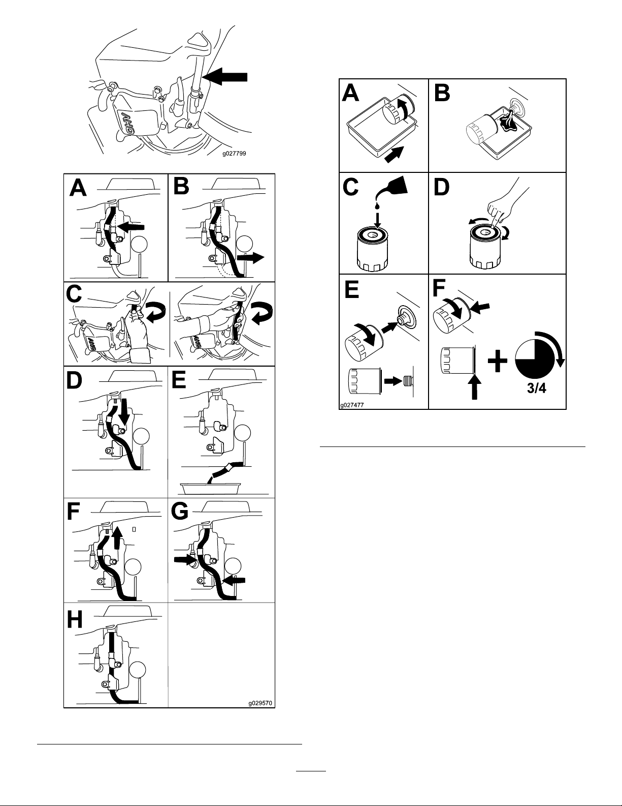
4.Draintheengineoil.
g029368
Figure37
34
Page 35
g027799
A
B
C
D
E
F
G
H
g029570
5.Changetheengine-oillter(Figure39).
B
A
C D
E
F
3/4
g027477
Note:Ensurethattheoil-ltergaskettouchesthe
engineandthenturnthelteranextra3/4turn.
g027799
g027477
Figure39
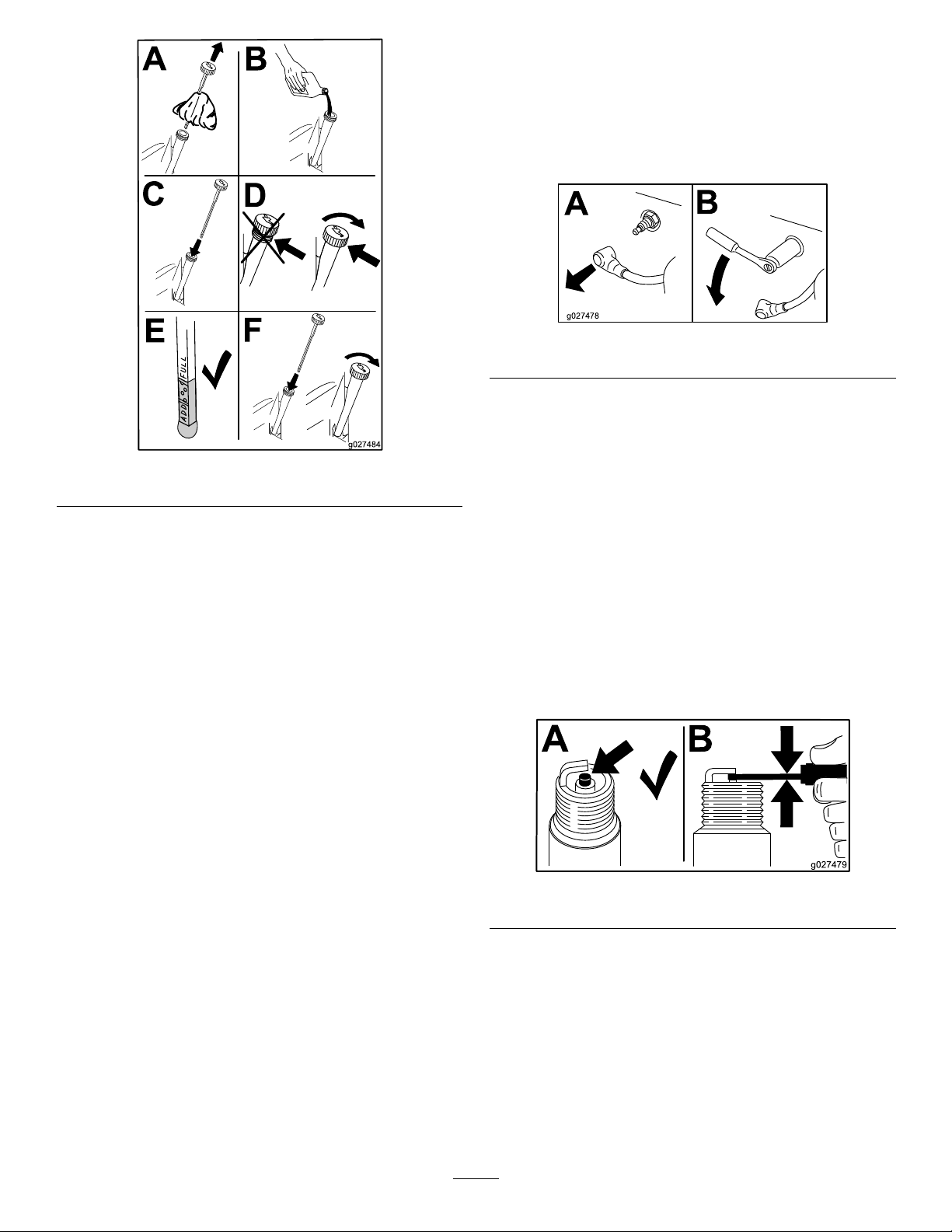
6.Slowlypourapproximately80%ofthespeciedoil
intothellertubeandslowlyaddtheadditionaloilto
bringittotheFullmark(Figure40).
Figure38
g029570
35
Page 36
B
A
C
D
E
F
g027484
Figure40
B
A
g027478
B
A
g027479
RemovingtheSparkPlug
1.DisengagethePTOandmovethemotion-control
leverstothePARKposition.
2.Shutofftheengine,removethekey ,andwaitforall
movingpartstostopbeforeleavingtheoperating
position.
g027478
Figure41
Note:Duetothedeeprecessaroundthesparkplug,
blowingoutthecavitywithcompressedairisthemost
g027484
effectivemethodforcleaning.Thesparkplugismost
accessiblewhentheblowerhousingisremovedfor
cleaning.
ServicingtheSparkPlug
ServiceInterval:Every100hours/Yearly(whichevercomes
rst)—Checkthesparkplug(s).
Every200hours/Every2years(whichevercomes
rst)—Replacethesparkplug(s).
Makesurethattheairgapbetweenthecenterandside
electrodesiscorrectbeforeinstallingthesparkplug.Use
aspark-plugwrenchforremovingandinstallingthespark
plug(s)andagappingtool/feelergaugetocheckandadjust
theairgap.Installanewsparkplug(s)ifnecessary.
Type:Champion
Airgap:0.76mm(0.03inch)
®
RN9YCorNGK
®
BPR6ES
CheckingtheSparkPlug
Important:Donotcleanthesparkplug(s).Always
replacethesparkplug(s)whenithas:ablackcoating,
wornelectrodes,anoilylm,orcracks.
Ifyouseelightbrownorgrayontheinsulator,theengineis
operatingproperly .Ablackcoatingontheinsulatorusually
meanstheaircleanerisdirty.
Setthegapto0.76mm(0.03inch).
g027479
Figure42
36
Page 37
InstallingtheSparkPlug
B
A
25-30 N-m
18.5-22.1 ft-lb
g027960
C
D
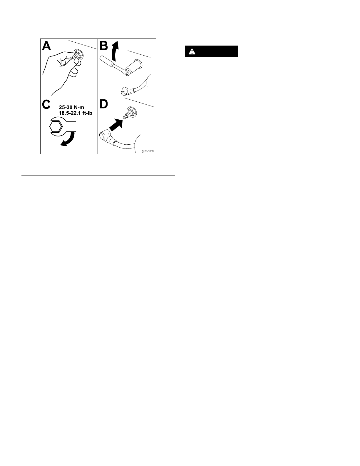
Tightenthesparkplug(s)to25to30N∙m(18.5to22.1ft-lb).
FuelSystem
Maintenance
DANGER
Incertainconditions,fuelisextremelyammable
andhighlyexplosive.Areorexplosionfromfuel
canburnyou,others,andcandamageproperty.
•Performanyfuel-relatedmaintenancewhenthe
engineiscold.Dothisoutdoorsinanopenarea.
Wipeupanyfuelthatspills.
•Neversmokewhendrainingfuel,andstayaway
fromanopenameorwhereasparkmayignite
thefuelfumes.
Figure43
CleaningtheCoolingSystem
Cleantheairintakescreenfromgrassanddebrisbeforeeach
use.
1.Disengagetheblade-controlswitchandmovethe
motion-controlleverstothePARKposition.
2.Shutofftheengine,removethekey ,andwaitforall
movingpartstostopbeforeleavingtheoperating
position.
3.Removetheairlterfromtheengine.
4.Removetheengineshroud.
5.Topreventdebrisenteringtheairintake,installtheair
ltertothelterbase.
6.Cleandebrisandgrassfromtheparts.
7.Removetheairlterandinstalltheengineshroud.
g027960
ReplacingtheIn-LineFuel Filter
ServiceInterval:Every100hours/Yearly(whichevercomes
rst)—Checkthein-linefuellter.
Every200hours/Every2years(whichevercomes
rst)—Replacethein-linefuellter.
Neverinstalladirtylterifitisremovedfromthefuelline.
1.Parkthemachineonalevelsurfaceanddisengagethe
blade-controlswitch.
2.Ensurethatthebrakeisengaged,shutofftheengine,
removethekey ,andwaitforallmovingpartstostop
beforeleavingtheoperatingposition.
8.Installtheairlter.
37
Page 38
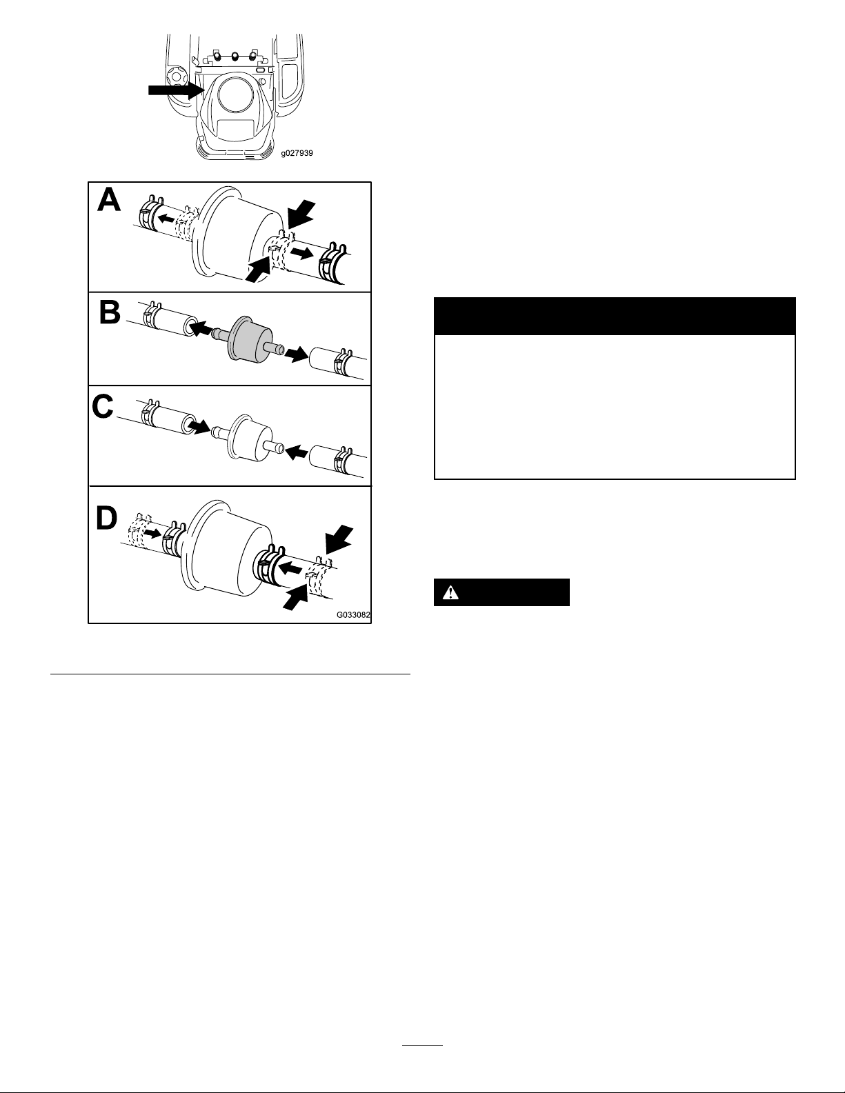
g027939
ElectricalSystem
Maintenance
ElectricalSystemSafety
g027939
•Disconnectthebatterybeforerepairingthemachine.
Disconnectthenegativeterminalrstandthepositive
last.Connectthepositiveterminalrstandthenegative
last.
•Chargethebatteryinanopen,well-ventilatedarea,away
fromsparksandames.Unplugthechargerbefore
connectingordisconnectingthebattery.Wearprotective
clothinganduseinsulatedtools.
WARNING
CALIFORNIA
Proposition65Warning
Batteryposts,terminals,andrelated
accessoriescontainleadandleadcompounds,
chemicalsknowntotheStateofCalifornia
tocausecancerandreproductiveharm.
Washhandsafterhandling.
Figure44
ServicingtheBattery
RemovingtheBattery
WARNING
g033082
Batteryterminalsormetaltoolscouldshortagainst
metalmachinecomponentscausingsparks.Sparks
cancausethebatterygassestoexplode,resulting
inpersonalinjury.
•Whenremovingorinstallingthebattery,donot
allowthebatteryterminalstotouchanymetal
partsofthemachine.
•Donotallowmetaltoolstoshortbetween
thebatteryterminalsandmetalpartsofthe
machine.
1.Parkthemachineonalevelsurfaceanddisengagethe
blade-controlswitch.
2.Movethemotion-controlleversoutwardtothePARK
position,shutofftheengine,removethekey,and
waitforallmovingpartstostopbeforeleavingthe
operatingposition.
3.Raisetheseattoaccessthebattery.
4.Disconnectthenegative(black)groundcablefromthe
batterypost(Figure45).
Note:Retainallfasteners.
38
Page 39
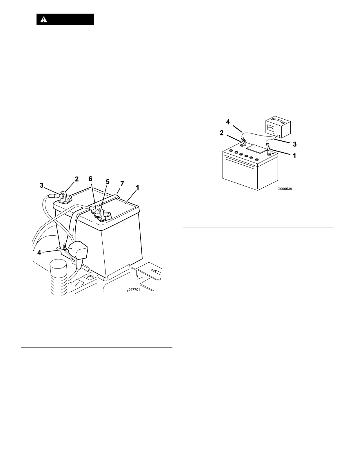
WARNING
g017701
2
3
4
5
6
7
1
Incorrectbattery-cableroutingcoulddamage
themachineandcablescausingsparks.
Sparkscancausethebatterygassesto
explode,resultinginpersonalinjury.
ChargingtheBattery
ServiceInterval:Beforestorage—Chargethebatteryand
disconnectthebatterycables.
1.Removethebatteryfromthechassis;refertoRemoving
theBattery(page38).
•Alwaysdisconnectthenegative(black)
batterycablebeforedisconnectingthe
positive(red)cable.
•Alwaysconnectthepositive(red)battery
cablebeforeconnectingthenegative
(black)cable.
5.Slidetherubbercoverupthepositive(red)cable.
6.Disconnectthepositive(red)cablefromthebattery
post(Figure45).
Note:Retainallfasteners.
7.Removethebatteryhold-down(Figure45),andliftthe
batteryfromthebatterytray .
2.Chargethebatteryforaminimumof1hourat6to
10A.
Note:Donotoverchargethebattery.
3.Whenthebatteryisfullycharged,unplugthecharger
fromtheelectricaloutlet,thendisconnectthecharger
leadsfromthebatteryposts(Figure46).
g000538
Figure46
1.Positive(+)batterypost3.Red(+)chargerlead
2.Negative(–)batterypost4.Black(–)chargerlead
1.Battery
2.Positive(+)batterypost
3.Bolt,washer,andnut7.Batteryhold-down
4.Terminalboot
InstallingtheBattery
1.Positionthebatteryinthetray(Figure45).
2.Usingthefastenerspreviouslyremoved,installthe
positive(red)batterycabletothepositive(+)battery
terminal.
3.Usingthefastenerspreviouslyremoved,installthe
g017701
Figure45
5.Negative(–)batterypost
6.Wingnut,washer,andbolt
negativebatterycabletothenegative(-)battery
terminal.
4.Slidetheredterminalbootontothepositive(red)
batterypost.
5.Securethebatterywiththehold-down(Figure45).
6.Lowertheseat.
39
Page 40
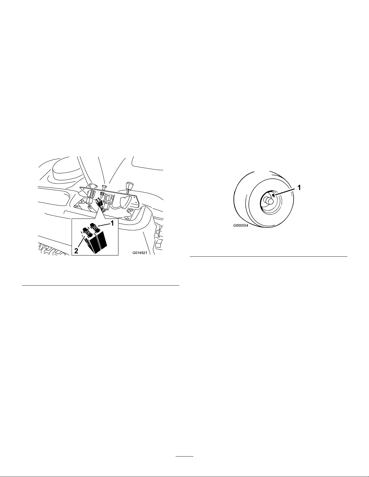
ServicingtheFuses
30
25
30
25
G014921
2
1
DriveSystem
Theelectricalsystemisprotectedbyfuses.Itrequires
nomaintenance;however,ifafuseblows,checkthe
component/circuitforamalfunctionorshort.
Fusetype:
•Main—F1(30A,blade-type)
•ChargeCircuit—F2(25A,blade-type)
1.Removethescrewssecuringthecontrolpaneltothe
machine.
Note:Retainallfasteners.
2.Liftthecontrolpaneuptoaccessthemainwireharness
andfuseblock(Figure47).
3.Toreplaceafuse,pulloutonthefusetoremoveit
(Figure47).
Maintenance
CheckingtheTirePressure
ServiceInterval:Every25hours—Checktirepressure.
Maintaintheairpressureinthefrontandreartiresas
specied.Uneventirepressurecancauseunevencut.Check
thepressureatthevalvestem(Figure48).Checkthetires
whentheyarecoldtogetthemostaccuratepressurereading.
Refertothemaximumpressuresuggestedbythetire
manufactureronthesidewallofthecasterwheeltires.
Formachineswith42-inchor50-inchdecks,inatetherear
drivewheeltiresto90kPa(13psi).
Formachineswith60-inchdecks,inatethefrontcastersand
reardrivewheeltiresto103kPa(15psi).
Figure47
1.Main(30A)2.Chargecircuit(25A)
4.Returnthecontrolpaneltoitsoriginalposition.
Note:Usethescrewsremovedpreviouslytosecure
thepaneltothemachine.
g000554
Figure48
1.Valvestem
g014921
40
Page 41
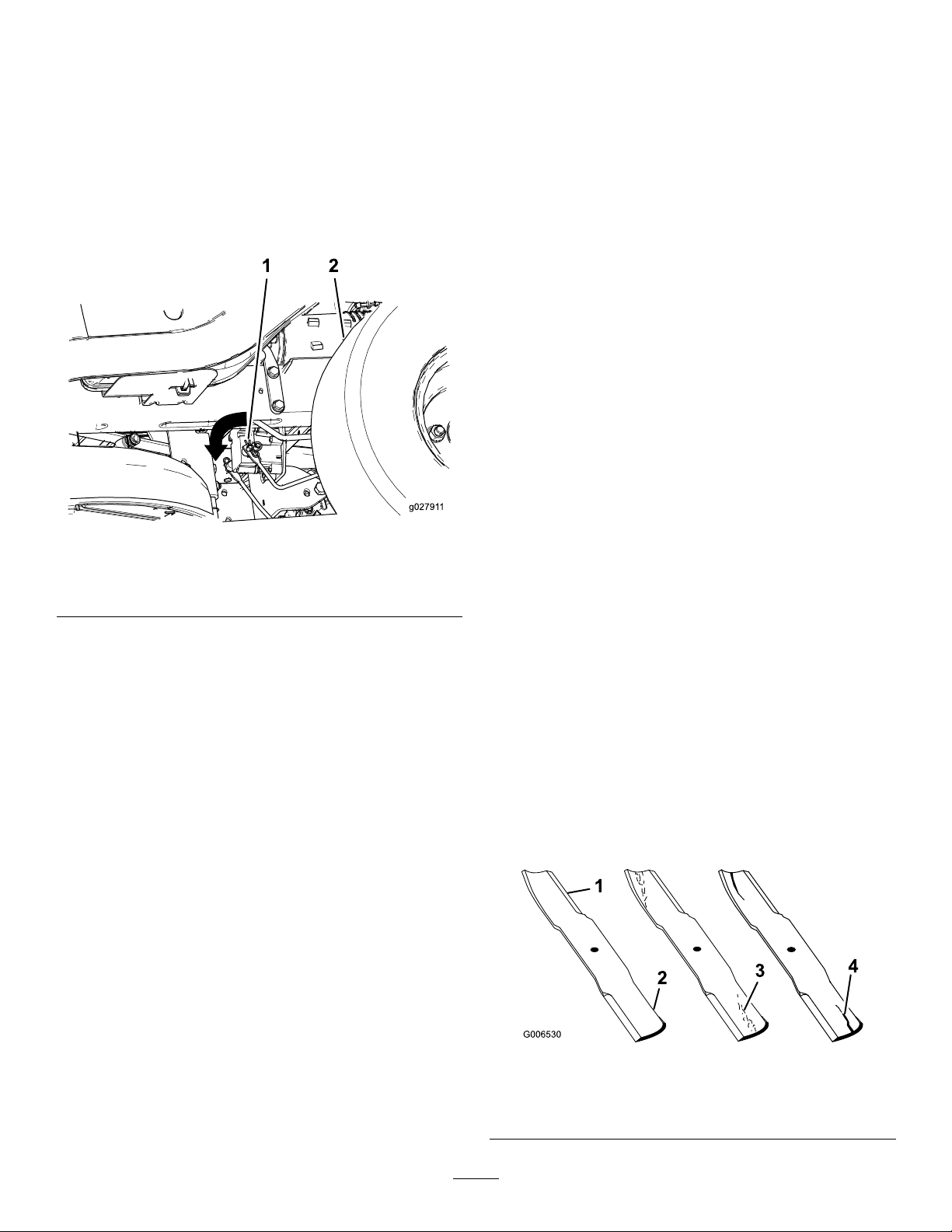
ReleasingtheElectricBrake
Youcanmanuallyreleasetheelectricbrakebyrotatingthe
linkarmsforward.Oncetheelectricbrakeisenergized,the
brakeresets.
1.TurntheignitionkeytotheOFFpositionordisconnect
thebattery.
2.Locatetheshaftontheelectricbrakewherethebrake
linkarmsareconnected(Figure49).
MowerMaintenance
ServicingtheCuttingBlades
Toensureasuperiorqualityofcut,keepthebladessharp.For
convenientsharpeningandreplacement,keepextrablades
onhand.
BladeSafety
3.Rotatetheshaftforwardtoreleasethebrake.
Figure49
1.Brake-linkarmontheelectricbrakecontrolmodule
2.Left,reartire
Awornordamagedbladecanbreak,andapieceoftheblade
couldbethrowntowardyouorbystanders,resultinginserious
personalinjuryordeath.Tryingtorepairadamagedblade
mayresultindiscontinuedsafetycerticationoftheproduct.
•Inspectthebladesperiodicallyforwearordamage.
•Usecarewhencheckingtheblades.Wrapthebladesor
weargloves,andusecautionwhenservicingtheblades.
Onlyreplaceorsharpentheblades;neverstraightenor
weldthem.
•Onmulti-bladedmachines,takecareasrotating1blade
cancauseotherbladestorotate.
BeforeInspectingorServicingthe
g027911
Blades
1.Parkthemachineonalevelsurface,disengage
theblade-controlswitch(PTO),andmovethe
motion-controlleversoutwardtothePARKposition.
2.Shutofftheengine,removethekey,anddisconnectthe
spark-plugwiresfromthesparkplugs.
InspectingtheBlades
ServiceInterval:Beforeeachuseordaily
1.Inspectthecuttingedges(Figure50).
2.Iftheedgesarenotsharporhavenicks,removeand
sharpentheblade;refertoSharpeningtheBlades(page
43).
3.Inspecttheblades,especiallyinthecurvedarea.
4.Ifyounoticeanycracks,wear,oraslotforminginthis
area,immediatelyinstallanewblade(Figure50).
Figure50
1.Cuttingedge3.Wear/slotforming
2.Curvedarea4.Crack
41
g006530
Page 42
CheckingforBentBlades
G014972
1
2
3
G014973
1
2
3
G014974
1
2
3
G014973
1
2
3
Note:Themachinemustbeonalevelsurfaceforthe
followingprocedure.
1.Raisethemowerdecktothehighestheight-of-cut
position.
2.Whilewearingthicklypaddedgloves,orotheradequate
handprotection,slowlyrotatethebladetobemeasure
intoapositionthatallowseffectivemeasurementofthe
distancebetweenthecuttingedgeandthelevelsurface
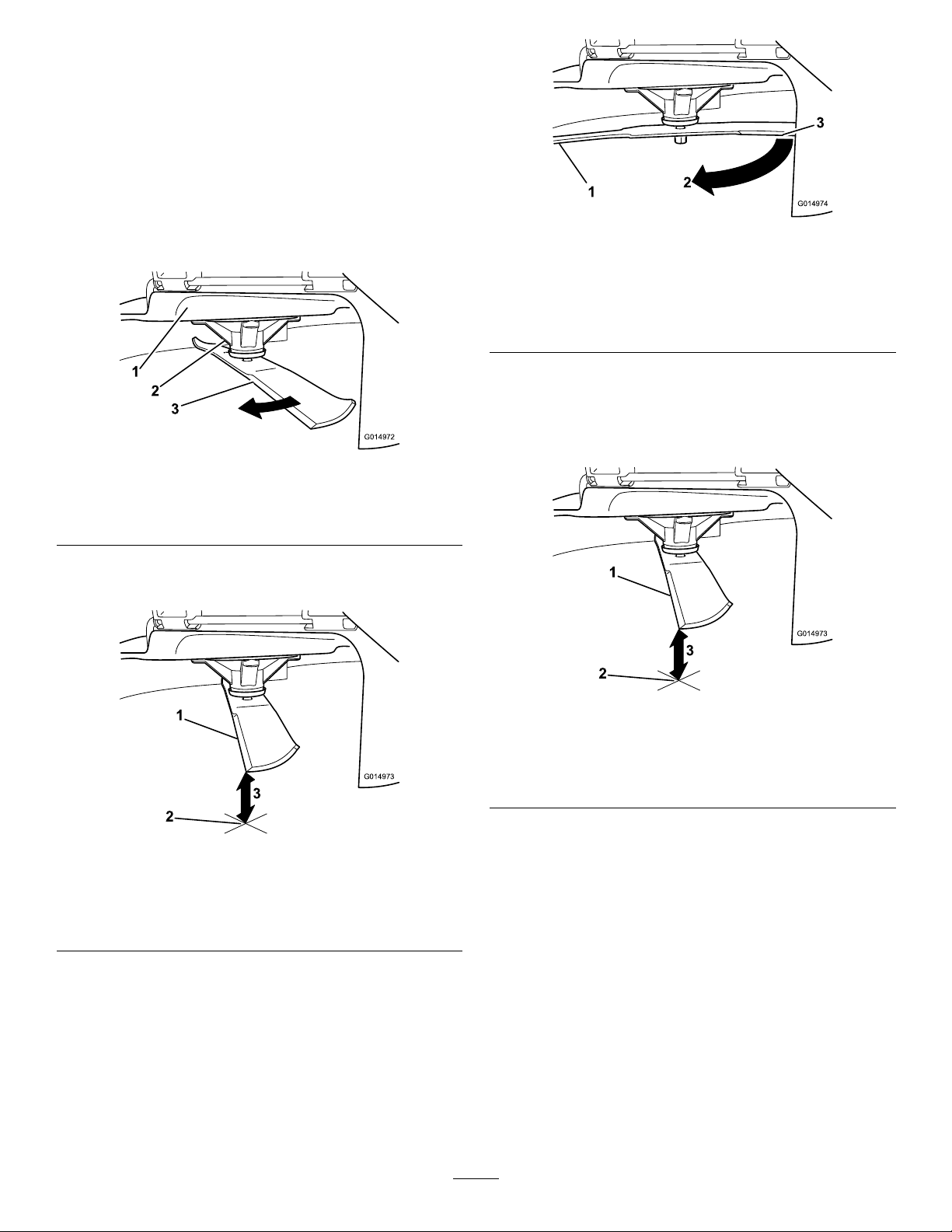
themachineison(Figure51).
Figure51
1.Deck3.Blade
2.Spindlehousing
g014974
Figure53
1.Blade(sidepreviouslymeasured)
2.Measurement(positionusedpreviously)
3.Opposingsideofbladebeingmovedintomeasurement
position
5.Measurefromthetipofthebladetotheatsurface
(Figure54).
Note:Thevarianceshouldbenomorethan3mm
g014972
(1/8inch).
3.Measurefromthetipofthebladetotheatsurface
(Figure52).
Figure52
1.Blade(inpositionformeasuring)
2.Levelsurface
3.Measureddistancebetweenbladeandthesurface(A)
4.Rotatethesameblade180degreessothattheopposing
cuttingedgeisnowinthesameposition(Figure53).
g014973
Figure54
1.Oppositebladeedge(inpositionformeasuring)
2.Levelsurface
3.Secondmeasureddistancebetweenbladeandsurface(B)
g014973
A.IfthedifferencebetweenAandBisgreaterthan
3mm(1/8inch),replacethebladewithanew
blade;refertoRemovingtheBlades(page43)and
InstallingtheBlades(page43).
Note:Ifabentbladeisreplacedwithanew
blade,andthedimensionobtainedcontinuesto
exceed3mm(1/8inch),thebladespindlecould
bebent.ContactanAuthorizedToroDealerfor
service.
B.Ifthevarianceiswithinconstraints,movetothe
nextblade.
6.Repeatthisprocedureoneachblade.
42
Page 43
RemovingtheBlades
G027833
Replacethebladesiftheyhitasolidobject,orifthebladeis
outofbalanceorbent.
1.Holdthebladeendusingaragorthicklypaddedglove.
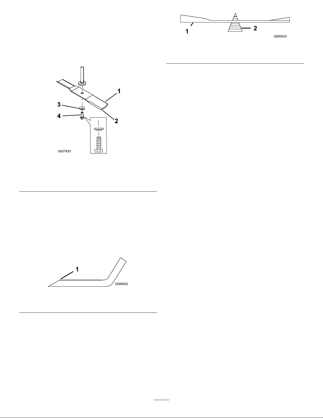
2.Removethebladebolt,curvedwasher,andbladefrom
thespindleshaft(Figure55).
Figure55
1.Sailareaoftheblade
2.Blade
3.Curvedwasher
4.Bladebolt
5.Bladestiffener
g000553
Figure57
1.Blade2.Balancer
3.Repeatthisprocedureuntilthebladeisbalanced.
InstallingtheBlades
1.Installthebladeontothespindleshaft(Figure55).
Important:Thecurvedpartoftheblademust
pointupwardtowardtheinsideofthemowerto
ensurepropercutting.
2.Installthecurvedwasher(cuppedsidetowardthe
blade)andthebladebolt(Figure55).
3.Torquethebladeboltto47to88N∙m(35to65ft-lb).
g027833
LevelingtheMowerDeck
Checktoensurethatthemowerdeckislevelanytimeyou
installthemowerorwhenyouseeanunevencutonyour
lawn.
SharpeningtheBlades
1.Usealetosharpenthecuttingedgeatbothendsof
theblade(Figure56).
Note:Maintaintheoriginalangle.
Note:Thebladeretainsitsbalanceifthesameamount
ofmaterialisremovedfrombothcuttingedges.
Figure56
1.Sharpenatoriginalangle.
2.Checkthebalanceofthebladebyputtingitonablade
balancer(Figure57).
Note:Ifthebladestaysinahorizontalposition,the
bladeisbalancedandcanbeused.
Note:Ifthebladeisnotbalanced,lesomemetaloff
theendofthesailareaonly(Figure56).
Themowerdeckmustbecheckedforbentbladespriorto
leveling;anybentbladesmustberemovedandreplaced;refer
totheCheckingforBentBlades(page42)beforecontinuing.
Themowerdeckmustbeleveledside-to-siderstthenthe
fronttorearslopecanbeadjusted.
Requirements:
•Themachinemustbeonalevelsurface.
•Alltiresmustbeproperlyinated;refertoCheckingthe
TirePressure(page40).
LevelingfromSidetoSide
g000552
1.Parkthemachineonalevelsurfaceanddisengagethe
blade-controlswitch.
2.Movethemotion-controlleversoutwardtothePARK
position,shutofftheengine,removethekey,and
waitforallmovingpartstostopbeforeleavingthe
operatingposition.
3.Settheheight-of-cutlevertomiddleposition.
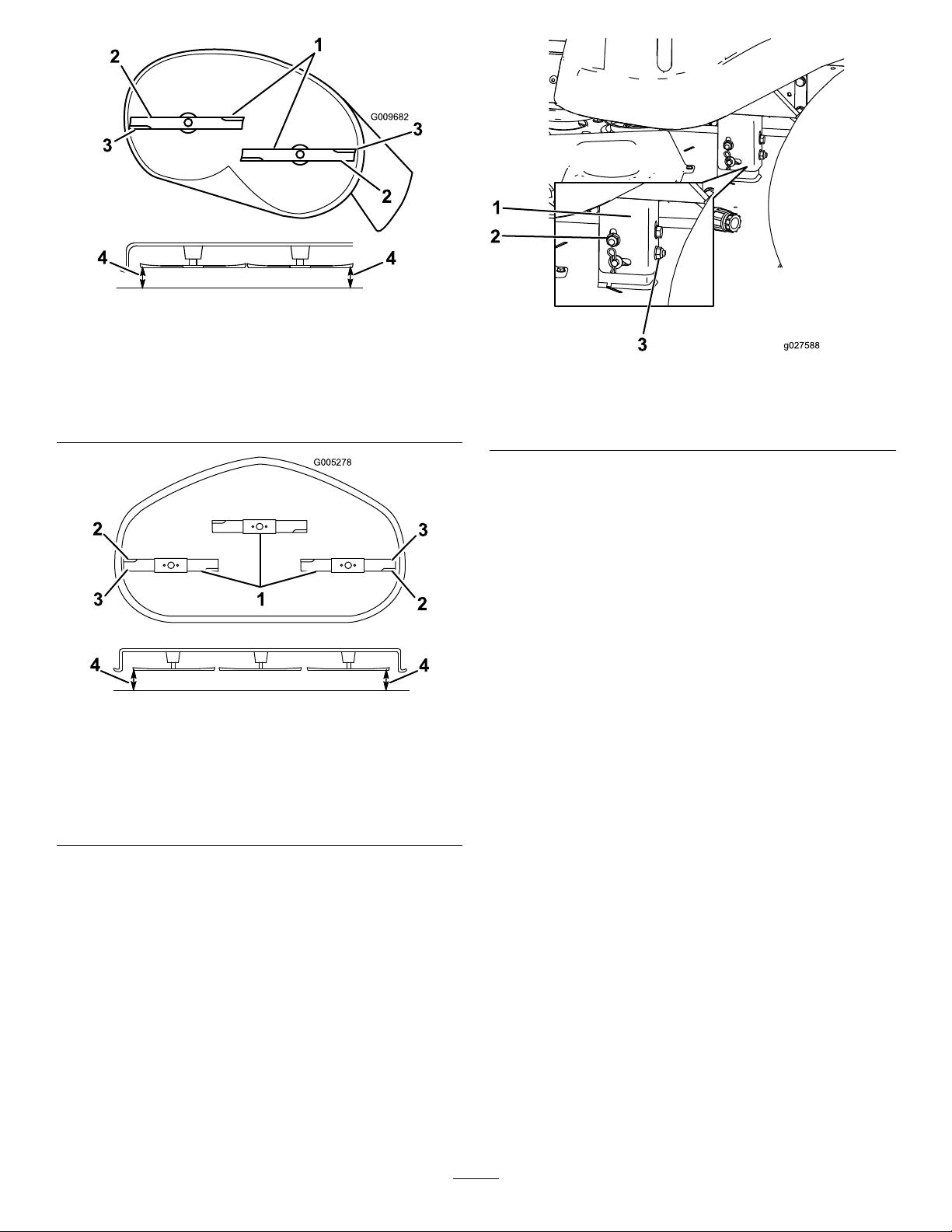
4.Carefullyrotatethebladessothattheyareallsideto
side(Figure58andFigure59).
43
Page 44
G009682
1
2
2
3
3
4
4
g009682
G005278
1
2
2
3
3
4
4
Figure58
MowerDeckswith2Blades
1.Bladessidetoside
2.Sailareaofblade4.Measurefromthetipofthe
3.Outsidecuttingedges
bladetotheatsurface
here
Figure60
1.Hangerbracket3.Rearnut
2.Sidelockingnut
g027588
9.Checktheside-to-sideadjustmentsagain.Repeatthis
procedureuntilthemeasurementsarecorrect.
10.Continuelevelingthemowerdeckbycheckingthe
front-to-rearbladeslope;refertoAdjustingthe
Front-to-RearBladeSlope(page44).
AdjustingtheFront-to-RearBlade
Slope
Checkthefront-to-rearbladelevelanytimeyouinstallthe
mower.Ifthefrontofthemowerismorethan7.9mm
g005278
Figure59
MowerDeckswith3Blades
1.Bladessidetoside
2.Sailareaofblade4.Measurefromthetipofthe
3.Outsidecuttingedges
bladetotheatsurface
here
5.Measurebetweentheoutsidecuttingedgesandtheat
surface(Figure58andFigure59).
Note:Ifbothmeasurementsarenotwithin5mm
(3/16inch),anadjustmentisrequired;continuewith
thisprocedure.
6.Movetotheleftsideofthemachine.
7.Loosenthesidelockingnut.
(5/16inch)lowerthantherearofthemower,adjusttheblade
levelusingthefollowinginstructions:
1.Parkthemachineonalevelsurfaceanddisengagethe
blade-controlswitch.
2.Movethemotion-controlleversoutwardtothePARK
position,shutofftheengine,removethekey,and
waitforallmovingpartstostopbeforeleavingthe
operatingposition.
3.Settheheight-of-cutlevertomiddleposition.
Note:Checkandadjusttheside-to-sidebladelevel
ifyouhavenotcheckedthesetting;refertoLeveling
fromSidetoSide(page43).
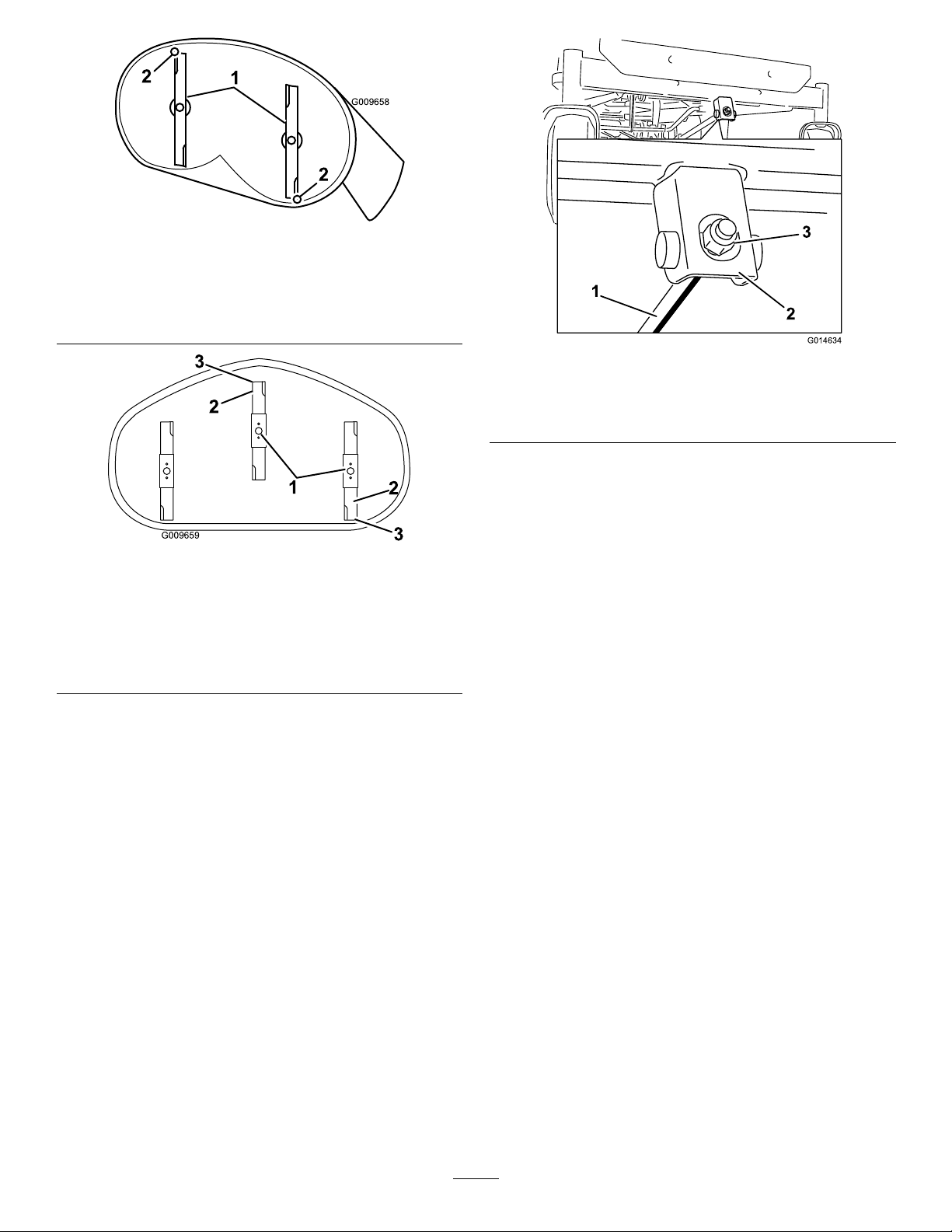
4.Carefullyrotatethebladessotheyarefacingfrontto
rear(Figure61andFigure62).
8.Raiseorlowertheleftsideofthemowerdeckby
rotatingtherearnut(Figure60).
Note:Rotatetherearnutclockwisetoraisethemower
deck;rotatetherearnutcounter-clockwisetolowerthe
mowerdeck.(Figure60).
44
Page 45
G009658
1
2
2
Figure61
G009659
1
2
3
2
3
G014634
1
2
3
MowerDeckswith2Blades
1.Bladesfronttorear
2.Measurefromthetipofthebladetotheatsurfacehere
Figure62
MowerDeckswith3Blades
1.Bladesfronttorear3.Measurefromthetipofthe
bladetotheatsurface
here.
2.Outsidecuttingedges
g009658
g014634
Figure63
1.Adjustingrod3.Locknut
2.Adjustingblock
7.For60-inchmowerdecks,adjustthefront-to-rear
bladeslopeasfollows:
A.Loosentheadjustmentnutontheleftadjusting
rod(Figure62).
g009659
B.Toraisethefrontofthemower,tightenthe
adjustmentnutontherightadjustingrod.
C.Tolowerthefrontofthemower,loosenthe
adjustmentnutontherightadjustingrod.
D.Tightentheadjustmentnutontheleftadjustment
rodsothatthereistensionontheleftdeckrod.
5.Measurefromthetipofthefrontbladetotheat
surface,andthetipoftherearbladetotheatsurface
(Figure61andFigure62).
Note:Ifthefrontbladetipisnot1.6to7.9mm
(1/16to5/16inch)lowerthantherearbladetip,adjust
thefrontlocknutfor42-inch,50-inch,and54-inch
decks;adjustthe2frontlocknutsthesameamountfor
60-inchdecks.
6.For42-inch,50-inch,and54-inchmowerdecks,
adjustthefront-to-rearbladeslopeasfollows:
A.Rotatetheadjustmentnutinthefrontofthe
mower(Figure63).
B.Toraisethefrontofthemower,tightenthe
adjustmentnut.
C.Tolowerthefrontofthemower,loosenthe
adjustmentnut.
D.Afteradjustment,checkthefront-to-rearslope
again,continueadjustingthenutuntilthefront
bladetipis1.6to7.9mm(1/16to5/16inch)
lowerthantherearbladetip(Figure61andFigure
62).
8.Whenthefront-to-rearbladeslopeiscorrectcheckthe
side-to-sidelevelofthemoweragain,refertoLeveling
fromSidetoSide(page43).
RemovingtheMowerDeck
1.Parkthemachineonalevelsurfaceanddisengagethe
blade-controlswitch.
2.Movethemotion-controlleversoutwardtothePARK
position,shutofftheengine,removethekey,and
waitforallmovingpartstostopbeforeleavingthe
operatingposition.
3.Lowertheheight-of-cutlevertothelowestposition.
4.Removethehairpincotterfromthefrontsupportrod
andremovetherodfromthedeckbracket(Figure64).
Note:For60-inchdecks,removethe2hairpincotters
fromthefrontsupportrodsandremovethe2rods
fromthedeckbracket
45
Page 46
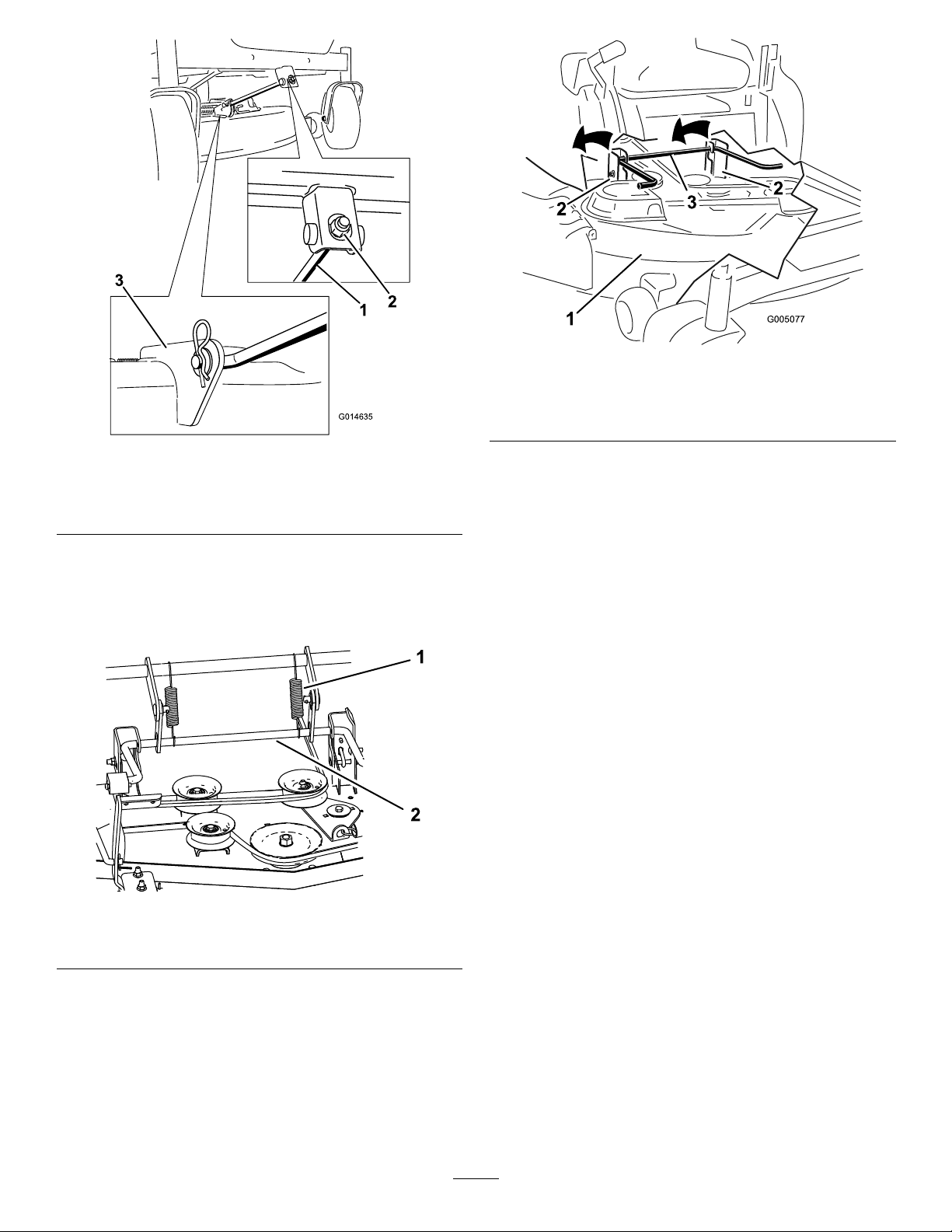
G014635
1
2
3
2
2
3
G005077
1
2
2
3
Figure66
g005077
Figure64
1.Frontsupportrod3.Deckbracket
2.Lockingnut
5.Carefullylowerthefrontofthemowerdecktothe
ground.
6.For60-inchdecks,removethe2deck-liftsprings
(Figure64).
1.Mowerdeck
2.Hangerbracket
g014635
3.Rearliftrod
8.Slidethemowerdeckrearwardtoremovethemower
beltfromtheenginepulley.
9.Slidethemowerdeckoutfromunderneaththe
machine.
Note:Retainallpartsforfutureinstallation.
InstallingtheMower
1.Parkthemachineonalevelsurfaceanddisengagethe
blade-controlswitch.
2.Movethemotion-controlleversoutwardtothePARK
position,shutofftheengine,removethekey,and
waitforallmovingpartstostopbeforeleavingthe
operatingposition.
3.Slidethemowerunderthemachine.
4.Lowertheheight-of-cutlevertothelowestposition.
5.Lifttherearofthemowerdeckandguidethehanger
bracketsovertherearliftrod(Figure66).
6.For60-inchdecks,installthe2deck-liftsprings(Figure
g188405
Figure65
1.Deck-liftspring(2)2.Rearliftrod
65).
7.Attachthefrontsupportrodtothemowerdeckwith
theclevispinandhairpincotter(Figure64).
Note:For60-inchdecks,attachthe2frontsupport
7.Liftthemowerdeckandhangerbracketsclearof
therearliftrodandlowerthemowercarefullytothe
ground(Figure66).
46
rodstothemowerdeckwiththe2clevispinsand2
hairpincotters.
8.Installthemowerbeltontotheenginepulley.
Page 47
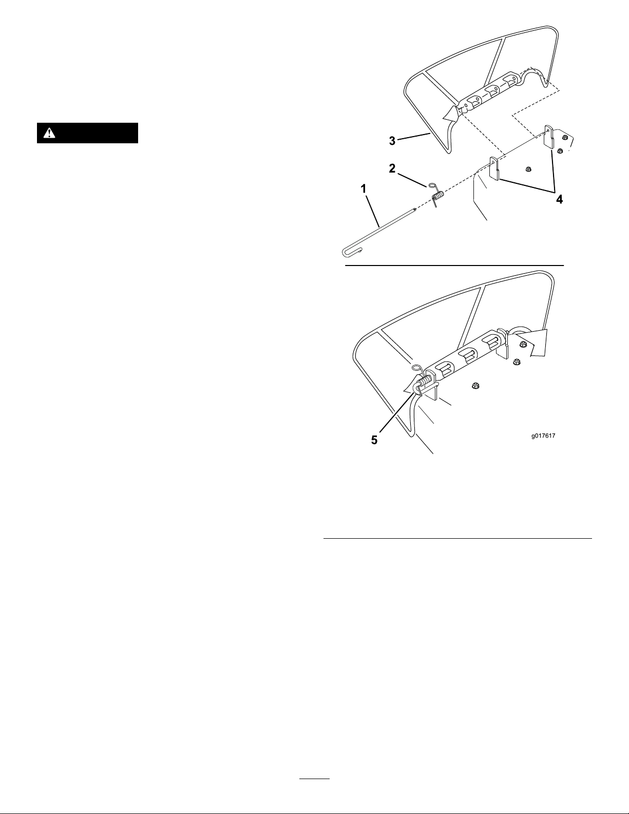
ReplacingtheGrassDeector
g017617
1
3
2
4
5
Machineswith42-inch,50-inch,or
60-inchMowerDecksOnly
ServiceInterval:Beforeeachuseordaily—Inspectthegrass
deectorfordamage.
WARNING
Anuncovereddischargeopeningcouldallowthe
lawnmowertothrowobjectsintheoperator'sor
bystander'sdirectionandresultinseriousinjury.
Also,contactwiththebladecouldoccur.Never
operatethemachinewithoutthegrassdeector,
thedischargecover,orthegrass-collectionsystem
inplace.
Neveroperatethemachinewithoutthegrass
deector,thedischargecover,orthegrass-collection
systeminplace.
1.Disengagethespringfromthenotchinthedeector
bracketandslidetherodoutoftheweldeddeck
brackets,spring,anddischargedeector(Figure67).
g017617
Figure67
1.Rod4.Deckbrackets
2.Spring5.Springinstalledoverthe
rod
3.Deector
2.Removethedamagedorworndischargedeector.
3.Positionthenewdischargedeectorwiththebracket
endsbetweentheweldedbracketsonthedeckas
showninFigure68.
4.Installthespringontothestraightendoftherod.
5.Positionthespringontherodasshowninsothe
shorterspringendiscomingfromundertherodbefore
thebendandgoingovertherodasitreturnsfromthe
bend.
6.Lifttheloopendofthespringandplaceitintothe
notchonthedeectorbracket(Figure68).
47
Page 48
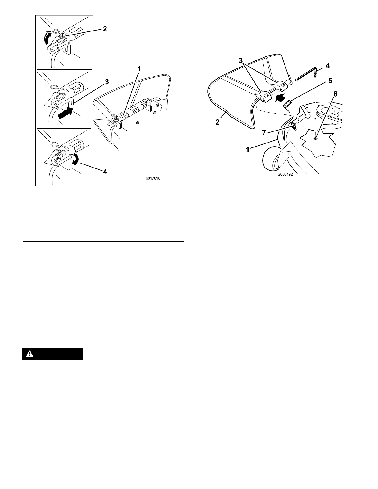
g017618
1
3
4
2
Figure68
G005192
1
2
3
4
5
6
7
1.Rodandspringassembly
installed
2.Loopendofthespring
installedintothenotchin
thedeectorbracket
3.Rod,shortend,moved
behindmowerbracket
4.Shortend,retainedby
mowerbracket.
7.Securetherodandspringassemblybytwistingitsothe
shortendoftherodisplacedbehindthefrontbracket
weldedtothedeck(Figure68).
Important:Thegrassdeectormustbespring
loadedinthedownposition.Liftthedeectorup
totestthatitsnapstothefulldownposition.
ReplacingtheGrassDeector
Machineswitha54-inchMowerDeck
Only
Inspectthegrassdeectorfordamagebeforeeachuse.
Replaceanydamagedpartsbeforeuse.
1.Removethenut(3/8inch)fromtherodunderthe
mower(Figure69).
g005192
g017618
1.Mowerdeck
2.Grassdeector6.Nut(3/8inch)
3.Grass-deectorbracket7.Shortstandoff
4.Rod
Figure69
5.Spring
2.Slidetherodoutoftheshortstandoff,thespring,and
thegrassdeector(Figure69).
3.Removethedamagedorworngrassdeector.
4.Replacethegrassdeector(Figure69).
5.Slidetherod(straightend),throughthe
rear-grass-deectorbracket.
6.Placethespringontherod,withtheendwiresdown
andbetweenthegrassdeectorbrackets.
7.Sliderodthroughthesecondgrass-deectorbracket
(Figure69).
8.Inserttherodatthefrontofthegrassdeectorinto
theshortstandoffonthedeck.
WARNING
Anuncovereddischargeopeningcouldallowthe
lawnmowertothrowobjectsintheoperator'sor
bystander'sdirectionandresultinseriousinjury.
Also,contactwiththebladecouldoccur.Never
operatethemachinewithoutthegrassdeector,
thedischargecover,orthegrass-collectionsystem
inplace.
Neveroperatethemachinewithoutthegrass
deector,thedischargecover,orthegrass-collection
systeminplace.
9.Securetherearendoftherodintothemowerwitha
nut(3/8inch)asshowninFigure69.
Important:Thegrassdeectormustbespring
loadedandinthedownposition.Liftthedeector
uptotestthatitsnapstothefulldownposition.
48
Page 49
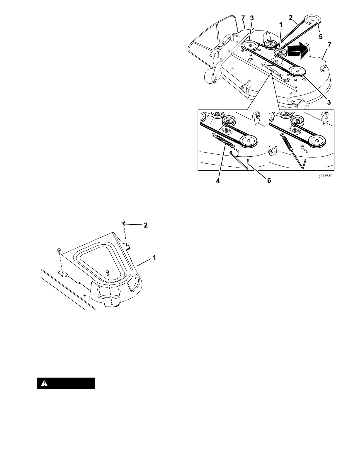
MowerBeltMaintenance
g017639
1
2
3
3
5
4
6
7
7
InspectingtheBelts
ServiceInterval:Every25hours—Checkthebeltsforwear
orcracks.
Checkthebeltsforcracks,frayededges,burnmarks,orany
otherdamage.Replacedamagedbelts.
ReplacingtheMowerBelt
Thesignsofawornbeltincludesquealingwhilethebeltis
rotating,bladesslippingwhilecuttinggrass,andfrayededges,
burnmarks,andcracksonthebelt.Replacethemowerbeltif
anyoftheseconditionsareevident.
1.Parkthemachineonalevelsurfaceanddisengagethe
blade-controlswitch.
2.Movethemotion-controlleversoutwardtothePARK
position,shutofftheengine,removethekey,and
waitforallmovingpartstostopbeforeleavingthe
operatingposition.
3.Settheheight-of-cutatthelowestcuttingpositionof
38mm(1-1/2inches).
g017639
Figure71
MowerDeckswith2Blades
4.Removethepulleycovers(Figure70).
Figure70
1.Cover2.Screw
5.Usingaspring-removaltool(ToroPartNo.92-5771),
removetheidlerspringfromthedeckhooktoremove
tensionontheidlerpulley ,androllthebeltoffthe
pulleys(Figure71).
1.Idlerpulley5.Enginepulley
2.Mowerbelt
3.Outsidepulley
4.Spring
g188324
6.Spring-removaltool
7.Mower-deckhandles
WARNING
Thespringisundertensionwheninstalled
andcancausepersonalinjury.
Becarefulwhenremovingthebelt.
49
Page 50
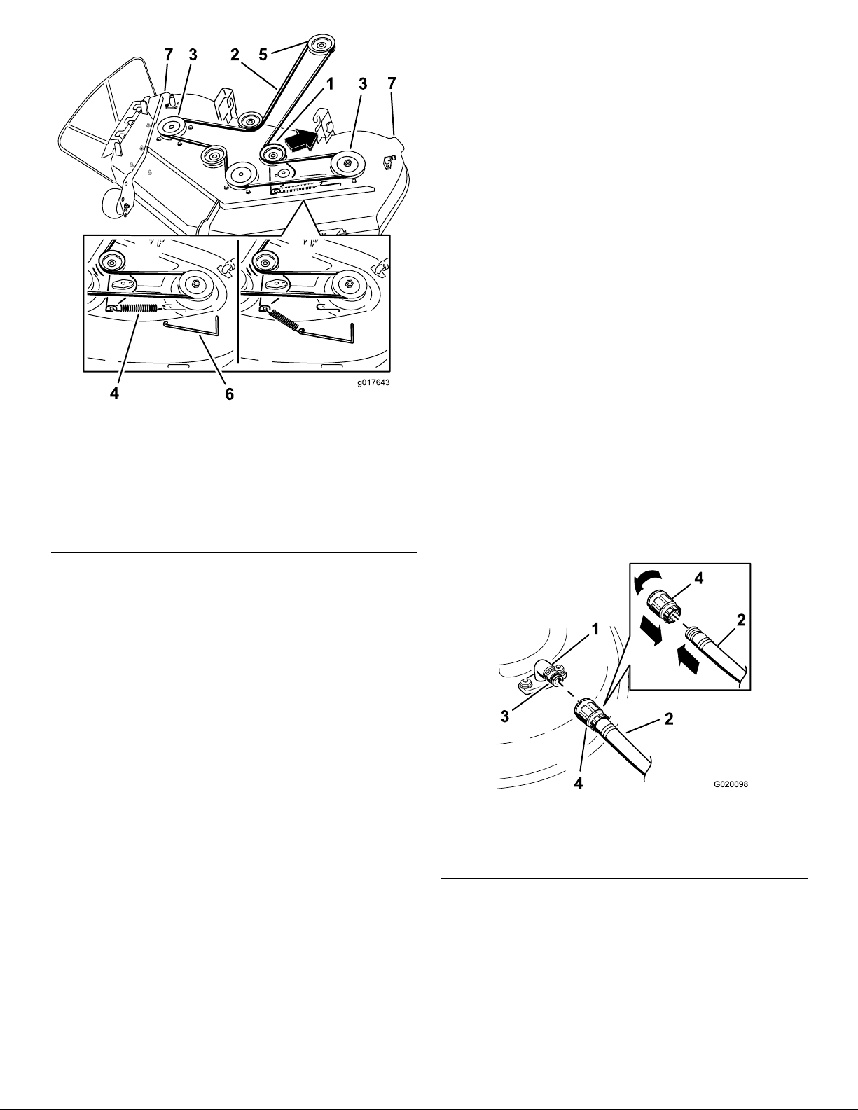
g017643
4
6
3 2 5
1 3
7
7
Cleaning
G020098
2
4
1
2
3
4
WashingtheUndersideofthe Mower
ServiceInterval:Aftereachuse—Cleanthemower-deck
housing.
Important:Y oucanwashthemachinewithamild
detergentandwater.Donotpressurewashthemachine.
Avoidexcessiveuseofwater,especiallynearthecontrol
panel,undertheseat,aroundtheengine,hydraulic
pumps,andmotors.
Washtheundersideofthemoweraftereachusetoprevent
grassbuildupforimprovedmulchactionandclipping
dispersal.
1.Parkthemachineonalevelsurfaceanddisengagethe
blade-controlswitch.
Figure72
MowerDeckswith3Blades
1.Idlerpulley5.Enginepulley
2.Mowerbelt
3.Outsidepulley
4.Spring
6.Spring-removaltool
7.Mower-deckhandles
6.Routethenewbeltaroundtheenginepulleyand
mowerpulleys(Figure71).
7.Usingaspring-removaltool,installtheidlerspringover
thedeckhook,andplacetensionontheidlerpulley
andmowerbelt(Figure71).
8.Installthepulleycovers(Figure70).
g017643
position,shutofftheengine,removethekey,and
waitforallmovingpartstostopbeforeleavingthe
operatingposition.
3.Attachthehosecouplingtotheendofthemower
washouttting,andturnthewateronhigh(Figure73).
Note:Spreadpetroleumjellyonthewashouttting
O-ringtomakethecouplingslideoneasierandprotect
theO-ring.
g020098
Figure73
2.Movethemotion-controlleversoutwardtothePARK
1.Washouttting3.O-ring
2.Hose
4.Lowerthemowertothelowestheight-of-cut.
4.Coupling
5.Sitontheseatandstarttheengine.
6.Engagetheblade-controlswitchandletthemowerrun
for1to3minutes.
7.Disengagetheblade-controlswitch,shutoffthe
engine,removetheignitionkey,andwaitforallmoving
partstostop.
50
Page 51

8.Turnthewateroffandremovethecouplingfromthe
washouttting.
Storage
Note:Ifthemowerisnotcleanafter1washing,soak
itandletitstandfor30minutes.Then,repeatthe
process.
9.Runthemoweragainfor1to3minutestoremove
excesswater.
WARNING
Abrokenormissingwashoutttingcould
exposeyouandotherstothrownobjectsor
bladecontact.Contactwithabladeorthrown
debriscancauseinjuryordeath.
•Replacebrokenormissingwashouttting
immediately,beforeusingmoweragain.
•Neverputyourhandsorfeetunderthe
mowerorthroughopeningsinthemower.
CleaningandStorage
1.Disengagetheblade-controlswitch,movethe
motion-controlleversoutwardtothePARKposition,
shutofftheengine,andremovethekey .
2.Removegrassclippings,dirt,andgrimefromthe
externalpartsoftheentiremachine,especiallythe
engine.Cleandirtandchafffromtheoutsideofthe
enginecylinderheadnsandblowerhousing.
Important:Youcanwashthemachinewithmild
detergentandwater.Donotpressurewashthe
machine.Avoidexcessiveuseofwater,especially
nearthecontrolpanel,undertheseat,aroundthe
engine,hydraulicpumps,andmotors.
3.Servicetheaircleaner;refertoServicingtheAir
Cleaner(page32).
4.Greaseandoilthemachine;refertoLubrication(page
32).
5.Changetheengineoilandlter;refertoChangingthe
EngineOilandOilFilter(page34).
6.Checkthetirepressure;refertoCheckingtheTire
Pressure(page40).
7.Chargethebattery;refertoChargingtheBattery(page
39).
8.Checktheconditionoftheblades;refertoServicing
theCuttingBlades(page41).
9.Preparethemachineforstoragewhennon-useoccurs
over30days.Preparethemachineforstorageas
follows.
A.Addapetroleumbasedstabilizer/conditionerto
thefuelinthetank.Followthemixinginstructions
fromthestabilizermanufacturer.Donotusean
alcoholbasedstabilizer(ethanolormethanol).
Note:Afuelstabilizer/conditionerismost
effectivewhenmixedwithfreshfuelandusedat
alltimes.
B.Runtheenginetodistributetheconditionedfuel
throughthefuelsystem(5minutes).
C.Shutofftheengine,waitforittocool,anddrain
thefueltank.
D.Restarttheengineandrunituntilitstops.
E.Startandruntheengineuntilitdoesnotstart.
F.Disposeoffuelproperly .Recyclepursuantto
localcodes.
Important:Donotstorefuelwith
stabilizer/conditionerover90days.
10.Removethesparkplug(s)andcheckitscondition;
refertoServicingtheSparkPlug(page36).Withthe
sparkplug(s)removedfromtheengine,pour30ml
(2tablespoons)ofengineoilintothesparkplughole.
51
Page 52

Usethestartertocranktheengineanddistributethe
oilinsidethecylinder.Installthesparkplug(s).Donot
installthewireonthesparkplug(s).
11.Cleananydirtandchafffromthetopofthemower.
12.Scrapeanyheavybuildupofgrassanddirtfromthe
undersideofthemower,thenwashthemowerwith
agardenhose.
13.Checktheconditionofthedriveandmowerbelts.
14.Checkandtightenallbolts,nuts,andscrews.Repairor
replaceanypartthatiswornordamaged.
15.Paintallscratchedorbaremetalsurfaces.Paintis
availablefromyourAuthorizedServiceDealer.
16.Storethemachineinaclean,drygarageorstoragearea.
Removethekeyfromtheignitionswitchandkeepit
inamemorableplace.Coverthemachinetoprotect
itandkeepitclean.
52
Page 53

Troubleshooting
Problem
Theengineoverheats.
Thestarterdoesnotcrank.
Theenginedoesnotstart,startshard,or
failstokeeprunning.
PossibleCauseCorrectiveAction
1.Theengineloadisexcessive.1.Reducethegroundspeed.
2.Theoillevelinthecrankcaseislow.2.Addoiltothecrankcase.
3.Thecoolingnsandairpassages
undertheengineblowerhousingare
plugged.
4.Theaircleanerisdirty .
5.Dirt,water,orstalefuelisinthefuel
system.
1.Theblade-controlswitchisengaged.1.Movetheblade-controlswitchto
2.Themotion-controlleversarenotin
thePARKposition.
3.Thebatteryisdead.
4.Theelectricalconnectionsare
corrodedorloose.
5.Afuseisblown.5.Replacethefuse.
6.Arelayorswitchisdamaged.
1.Thefueltankisempty .1.Fillthefueltank.
2.Theaircleanerisdirty .
3.Thesparkplugwire(s)islooseor
disconnected.
4.Thesparkplug(s)ispitted,fouled,or
thegapisincorrect.
5.Thereisdirtinfuellter.5.Replacethefuellter.
6.Dirt,water,orstalefuelisinfuel
system.
7.Thereisincorrectfuelinthefueltank.7.Drainthetankandreplacethefuelwith
8.Theoillevelinthecrankcaseislow.8.Addoiltothecrankcase.
3.Removetheobstructionfromthe
coolingnsandairpassages.
4.Cleanorreplacetheair-cleaner
element.
5.ContactanAuthorizedServiceDealer.
Disengaged.
2.Movethemotion-controllevers
outwardtothePARKposition.
3.Chargethebattery.
4.Checktheelectricalconnectionsfor
goodcontact.
6.ContactanAuthorizedServiceDealer.
2.Cleanorreplacetheair-cleaner
element.
3.Installthewire(s)onthesparkplug.
4.Installanew,correctlygappedspark
plug(s).
6.ContactanAuthorizedServiceDealer.
thepropertype.
Theenginelosespower.
Themachinedoesnotdrive.
1.Theengineloadisexcessive.1.Reducethegroundspeed.
2.Theaircleanerisdirty .
3.Theoillevelinthecrankcaseislow.3.Addoiltothecrankcase.
4.Thecoolingnsandairpassages
undertheengineblowerhousingare
plugged.
5.Thesparkplug(s)ispitted,fouled,or
thegapisincorrect.
6.Thefuel-tankventisblocked.6.ContactanAuthorizedServiceDealer.
7.Thereisdirtinthefuellter.7.Replacethefuellter.
8.Dirt,water,orstalefuelisinthefuel
system.
9.Thereisincorrectfuelinthefueltank.9.Drainthetankandreplacethefuelwith
1.Thebypassvalvesareopen.
2.Thetractionbeltsareworn,loose,or
broken.
3.Thetractionbeltsareoffthepulleys.3.ContactanAuthorizedServiceDealer.
4.Thetransmissionhasfailed.4.ContactanAuthorizedServiceDealer.
2.Cleantheair-cleanerelement.
4.Removetheobstructionfromthe
coolingnsandairpassages.
5.Installanew,correctlygappedspark
plug(s).
8.ContactanAuthorizedServiceDealer.
thepropertype.
1.Closethetowvalves.
2.ContactanAuthorizedServiceDealer.
53
Page 54

Problem
PossibleCauseCorrectiveAction
Thereisanabnormalvibration.
Thecuttingheightisuneven.
Thebladesdonotrotate.
1.Theengine-mountingboltsareloose.1.Tightentheengine-mountingbolts.
2.Theenginepulley,idlerpulley,orblade
pulleyisloose.
3.Theenginepulleyisdamaged.
4.Thecuttingblade(s)is/arebentor
unbalanced.
5.Ablade-mountingboltisloose.5.Tightentheblade-mountingbolt.
6.Abladespindleisbent.
1.Theblade(s)isnotsharp.1.Sharpentheblade(s).
2.Acuttingblade(s)is/arebent.2.Installanewcuttingblade(s).
3.Themowerisnotlevel.
4.Ananti-scalpwheelisnotsetcorrectly .4.Adjusttheanti-scalpwheelheight.
5.Theundersideofthemowerisdirty.5.Cleantheundersideofthemower.
6.Thetirepressureisincorrect.6.Adjustthetirepressure.
7.Abladespindleisbent.
1.Thedrivebeltisworn,loose,orbroken.1.Installanewdrivebelt.
2.Thedrivebeltisoffthepulley.
3.Thepower-takeoff(PTO)switchor
PTOclutchisfaulty.
4.Themowerbeltisworn,loose,or
broken.
2.Tightentheappropriatepulley.
3.ContactanAuthorizedServiceDealer.
4.Installanewcuttingblade(s).
6.ContactanAuthorizedServiceDealer.
3.Levelthemowerfromside-to-sideand
front-to-rear.
7.ContactanAuthorizedServiceDealer.
2.Installthedrivebeltandcheckthe
adjustingshaftsandbeltguidesforthe
correctposition.
3.ContactanAuthorizedServiceDealer.
4.Installanewmowerbelt.
54
Page 55
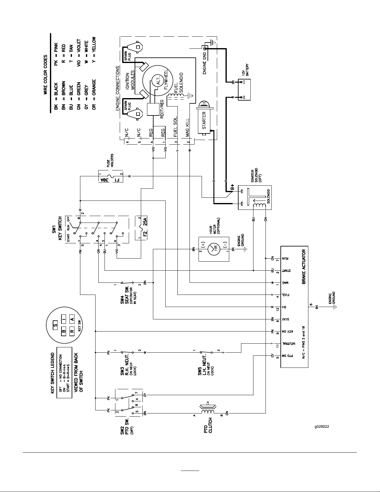
Schematics
ElectricalDiagram(Rev .A)
55
g028022
Page 56

TheToroWarranty
LimitedWarranty(seewarrantyperiodsbelow)
TimeCutter
ConditionsandProductsCovered
TheT oroCompanyanditsafliate,ToroWarrantyCompany ,pursuanttoan
agreementbetweenthem,jointlypromisetorepairtheT oroProductslisted
belowifdefectiveinmaterialsorworkmanship.
Thefollowingtimeperiodsapplyfromtheoriginaldateofpurchase:
Products
TimeCutterMowers
•Engines
TimeCutterMowersCommercialuse30days
•Engines
TimeCutterHDMowers
•Engines
CommercialUse
AllMowers
•Attachments1year
•Battery90daysPartsandLabor
•BeltsandTires90days
1
SomeenginesusedonT oroProductsarewarrantedbytheenginemanufacturer.
2
Residentialusemeansuseoftheproductonthesamelotasyourhome.Useatmorethanone
locationisconsideredcommercialuseandthecommercialusewarrantywouldapply.
3
Whicheveroccursrst.
Warrantymaybedeniedifthehourmeterisdisconnected,altered,or
showssignsofbeingtamperedwith.
1
—ResidentialuseKawasaki–3years
1
—Commercialuse
1
—Residentialand
WarrantyPeriod
ResidentialUse
Kohler–3years
Toro–3years
Kawasaki–3years
Kohler–90days
ToroSingleCylinder–90days
ToroT winCylinder–3years/300
3
Hours
3yearsor300Hours
3yearsor300Hours
1yearPartsonly
2
–3years
3
3
OwnerResponsibilities
YoumustmaintainyourToroProductbyfollowingthemaintenance
proceduresdescribedintheOperator'sManual.Suchroutinemaintenance,
whetherperformedbyadealerorbyyou,isatyourexpense.
InstructionsforObtainingWarrantyService
IfyouthinkthatyourT oroProductcontainsadefectinmaterialsor
workmanship,followthisprocedure:
1.ContactanyAuthorizedT oroServiceDealertoarrangeserviceat
theirdealership.Tolocateadealerconvenienttoyou,accessourweb
siteatwww .Toro.com.Youmayalsocallthenumberslistedinitem#3
tousethe24-hourT oroDealerlocatorsystem.
2.Bringtheproductandyourproofofpurchase(salesreceipt)tothe
ServiceDealer.Thedealerwilldiagnosetheproblemanddetermineif
itiscoveredunderwarranty.
3.IfforanyreasonyouaredissatisedwiththeServiceDealer’s
analysisorwiththeassistanceprovided,contactusat:
ToroWarrantyCompany
CustomerCareDepartment,RLCDivision
811 1LyndaleAvenueSouth
Bloomington,MN55420-1196
Tollfreeat866-216-6029(U.S.customers)
Tollfreeat866-216-6030(Canadiancustomers)
ItemsandConditionsNotCovered
Thereisnootherexpresswarrantyexceptforspecialemissionsystem
coverageandenginewarrantycoverageonsomeproducts.Thisexpress
warrantydoesnotcoverthefollowing:
•Costofregularmaintenanceserviceorparts,suchaslters,fuel,
lubricants,oilchanges,sparkplugs,airlters,bladesharpening
orwornblades,cable/linkageadjustments,orbrakeandclutch
adjustments
•Componentsfailingduetonormalwear
•Anyproductorpartwhichhasbeenaltered,misused,neglected,
requiresreplacementorrepairduetoaccidentsorlackofproper
maintenance
•Pickupanddeliverycharges
•RepairsorattemptedrepairsbyanyoneotherthananAuthorizedToro
ServiceDealer
•Repairsnecessaryduetofailuretofollowrecommendedfuel
procedure(consultOperator'sManualformoredetails)
–Removingcontaminantsfromthefuelsystemisnotcovered
–Useofoldfuel(morethanonemonthold)orfuelwhichcontains
morethan10%ethanolormorethat15%MTBE
–Failuretodrainthefuelsystempriortoanyperiodofnon-use
overonemonth
GeneralConditions
AllrepairscoveredbythesewarrantiesmustbeperformedbyanAuthorized
ToroServiceDealerusingT oroapprovedreplacementparts.
NeitherTheToroCompanynorToroWarrantyCompanyisliablefor
indirect,incidentalorconsequentialdamagesinconnectionwiththe
useoftheToroProductscoveredbythiswarranty,includingany
costorexpenseofprovidingsubstituteequipmentorserviceduring
reasonableperiodsofmalfunctionornon-usependingcompletionof
repairsunderthiswarranty.
Allimpliedwarrantiesofmerchantability(thattheproductistfor
ordinaryuse)andtnessforuse(thattheproductistforaparticular
purpose)arelimitedtothedurationoftheexpresswarranty.
Somestatesdonotallowexclusionsofincidentalorconsequential
damages,orlimitationsonhowlonganimpliedwarrantylasts,sothe
aboveexclusionsandlimitationsmaynotapplytoyou.
Thiswarrantygivesyouspeciclegalrights,andyoumayalsohaveother
rightswhichvaryfromstatetostate.
CountriesOtherthantheUnitedStatesorCanada
ThiswarrantyisnotvalidinMexico.CustomerswhohavepurchasedT oroproductsoutsidetheUnitedStatesorCanadashouldcontacttheirT oro
Distributor(Dealer)toobtainguaranteepoliciesforyourcountry,province,orstate.IfforanyreasonyouaredissatisedwithyourDistributor'sserviceor
havedifcultyobtainingguaranteeinformation,contacttheT oroimporter.Ifallotherremediesfail,youmaycontactusatT oroWarrantyCompany.
AustralianConsumerLaw:AustraliancustomerswillnddetailsrelatingtotheAustralianConsumerLaweitherinsidetheboxoratyourlocalT oro
Dealer.
374-0258RevJ
 Loading...