

Page 1
FormNo.3390-206RevA
g017600
GrandStand
®
Mower
With48in,52in,or60inTURBOFORCE
CuttingUnit
ModelNo.74583—SerialNo.315000001andUp
ModelNo.74588—SerialNo.315000001andUp
ModelNo.74589—SerialNo.315000001andUp
ModelNo.79589—SerialNo.315000001andUp
®
Registeratwww.T oro.com.
OriginalInstructions(EN)
*3390-206*A
Page 2
WARNING
G017731
1
CALIFORNIA
Proposition65Warning
Thisproductcontainsachemicalorchemicals
knowntotheStateofCaliforniatocausecancer,
birthdefects,orreproductiveharm.
Theengineexhaustfromthisproduct
containschemicalsknowntotheStateof
Californiatocausecancer,birthdefects,
orotherreproductiveharm.
ThissparkignitionsystemcomplieswithCanadianICES-002.
Important:Thisengineisnotequippedwithaspark
arrestermufer.ItisaviolationofCaliforniaPublic
ResourceCodeSection4442touseoroperatetheengine
onanyforest-covered,brush-covered,orgrass-covered
land.Otherstatesorfederalareasmayhavesimilarlaws.
WARNING
Removingstandardoriginalequipmentpartsand
accessoriesmayalterthewarranty,traction,and
safetyofthemachine.FailuretouseoriginalToro
partscouldcauseseriousinjuryordeath.Making
unauthorizedchangestotheengine,fuelorventing
system,mayviolateEPAandCARBregulations.
Replaceallpartsincluding,butnotlimitedto,tires,
belts,blades,andfuelsystemcomponentswith
originalToroparts.
YoumaycontactTorodirectlyatwww .Toro.comforproduct
andaccessoryinformation,helpndingadealer,ortoregister
yourproduct.
Wheneveryouneedservice,genuineT oroparts,oradditional
information,contactanAuthorizedServiceDealerorToro
CustomerServiceandhavethemodelandserialnumbersof
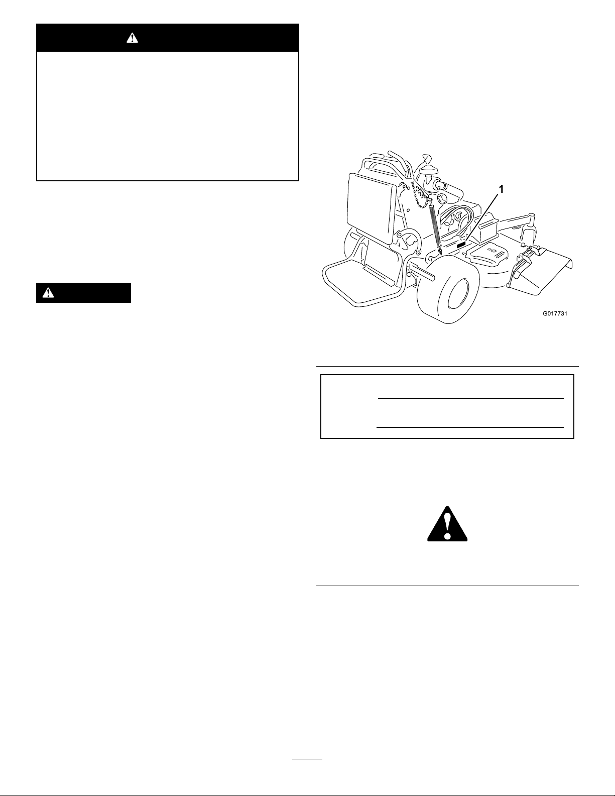
yourproductready.Figure1identiesthelocationofthe
modelandserialnumbersontheproduct.Writethenumbers
inthespaceprovided.
Figure1
1.Locationofthemodelandserialnumbers
ModelNo.
SerialNo.
Theenclosed
informationregardingtheUSEnvironmentalProtection
Agency(EPA)andtheCaliforniaEmissionControl
Regulationofemissionsystems,maintenance,and
warranty.Replacementsmaybeorderedthroughthe
enginemanufacturer.
Engine Owner's Man ual
issuppliedfor
Introduction
Thisrotaryblade,ridinglawnmowerisintendedtobe
usedbyprofessional,hiredoperators,orresidential
homeowners.Itisdesignedprimarilyforcuttinggrass
onwell-maintainedlawnsonresidentialorcommercial
properties.Itisnotdesignedforcuttingbrushorfor
agriculturaluses.
Readthisinformationcarefullytolearnhowtooperateand
maintainyourproductproperlyandtoavoidinjuryand
productdamage.Youareresponsibleforoperatingthe
productproperlyandsafely.
Thismanualidentiespotentialhazardsandhassafety
messagesidentiedbythesafetyalertsymbol(Figure2),
whichsignalsahazardthatmaycauseseriousinjuryordeath
ifyoudonotfollowtherecommendedprecautions.
Figure2
1.Safetyandalertsymbol
Thismanualuses2wordstohighlightinformation.
Importantcallsattentiontospecialmechanicalinformation
andNoteemphasizesgeneralinformationworthyofspecial
attention.
©2014—TheToro®Company
8111LyndaleAvenueSouth
Bloomington,MN55420
Contactusatwww.Toro.com.
2
PrintedintheUSA.
AllRightsReserved
Page 3

Contents
Safety...........................................................................4
SafeOperatingPractices...........................................4
ToroMowerSafety..................................................6
SlopeIndicator.......................................................7
SafetyandInstructionalDecals.................................8
ProductOverview.........................................................12
Controls...............................................................12
Specications........................................................14
Operation....................................................................14
AddingFuel...........................................................14
CheckingtheEngine-OilLevel.................................15
BreakinginaNewMachine......................................15
ThinkSafetyFirst...................................................15
OperatingtheParkingBrake....................................16
OperatingtheMower-Blade-ControlSwitch
(PTO)...............................................................16
OperatingtheThrottle............................................16
OperatingtheIgnitionSwitch..................................17
UsingtheFuelShut-offValve...................................17
StartingandStoppingtheEngine..............................17
TheSafety-InterlockSystem....................................19
OperatingthePlatform...........................................20
DrivingForwardorBackward..................................20
StoppingtheMachine.............................................22
UsingtheRotationIndicator....................................22
PushingtheMachinebyHand..................................22
TransportingtheMachine........................................22
LoadingtheMachine..............................................23
SideDischargingorMulchingtheGrass.....................23
AdjustingtheHeight-of-Cut....................................24
AdjustingtheAnti-ScalpRollers(for60-inch
modelsonly)......................................................24
AdjustingtheFlowBafe........................................24
PositioningtheFlowBafe......................................25
UsingtheMid-SizeWeight.......................................26
Maintenance.................................................................27
RecommendedMaintenanceSchedule(s)......................27
PremaintenanceProcedures........................................28
RaisingtheMowerforAccess...................................28
ReleasingtheCushionforRearAccess.......................29
Lubrication...............................................................30
LubricatingtheMachine..........................................30
GreasingtheFrontCasterPivots..............................30
LubricateCaster-WheelHubs..................................31
EngineMaintenance..................................................32
ServicingtheAirCleaner.........................................32
ServicingtheEngineOil..........................................33
ServicingtheSparkPlug..........................................35
CheckingtheSparkArrester(ifequipped)..................36
FuelSystemMaintenance...........................................36
DrainingtheFuelTank...........................................36
ServicingtheFuelFilter...........................................37
ServicingtheElectronicFuel-Injection
System..............................................................37
ElectricalSystemMaintenance....................................38
ServicingtheBattery...............................................38
ServicingtheFuses.................................................39
JumpStartingtheMachine.......................................40
DriveSystemMaintenance.........................................41
AdjustingtheTracking...........................................41
CheckingtheTirePressure......................................42
AdjustingtheCaster-PivotBearing............................42
ServicingtheCasterWheelsandBearings...................43
ServicingtheClutch................................................43
CheckingtheWheel-LugNuts..................................45
CheckingtheWheel-HubNuts.................................45
CoolingSystemMaintenance......................................45
CleaningtheAir-IntakeScreen.................................45
CleaningtheCoolingSystem....................................45
ServicingtheEngine-OilCooler...............................46
CleaningtheHydraulic-OilCooler............................46
ServicingtheHydraulic-OilCooler...........................46
BrakeMaintenance....................................................47
ServicingtheBrake.................................................47
BeltMaintenance......................................................49
ReplacingtheMower-DeckBelt...............................49
ReplacingthePump-driveBelt.................................50
ControlsSystemMaintenance.....................................51
AdjustingtheMotion-Control-Handle
Positions............................................................51
HydraulicSystemMaintenance....................................53
ServicingtheHydraulicSystem.................................53
MowerDeckMaintenance...........................................56
ServicingtheCuttingBlades.....................................56
CorrectingtheMowerQuality-of-Cut........................58
AdjustingtheDeck-LiftSpring.................................61
ReplacingtheGrassDeector..................................61
Cleaning...................................................................62
CleaningundertheMower.......................................62
DisposingoftheWaste............................................62
Storage........................................................................62
CleaningandStorage..............................................62
Troubleshooting...........................................................64
Schematics...................................................................66
3
Page 4

Safety
Improperuseormaintenancebytheoperatororowner
canresultininjury.Toreducethepotentialforinjury,
complywiththesesafetyinstructions,andpayattentionto
thesafetyalertsymbol,whichmeansCaution,Warning,or
Danger—“personalsafetyinstruction.”Failuretocomply
withtheinstructionsmayresultinpersonalinjuryor
death.
Important:Thismachinewasmanufacturedaccording
totheappropriateregulatorystandardsineffectatthe
timeofmanufacture.Modifyingthismachineinany
waymaycauseittobeoutofcompliancewiththose
standardsandwiththeinstructionsinthisOperator’s
Manual.Modicationstothismachineshouldonlybe
madebyeitherthemanufactureroranAuthorizedToro
Dealer.
Thisproductiscapableofamputatinghandsandfeet.Follow
allsafetyinstructionstoavoidseriousinjuryordeath.
Theowner/usercanpreventandisresponsibleforaccidents
orinjuriesoccurringtopeople,ordamagetoproperty.
Important:Theadditionofattachmentsmadeby
othermanufacturersthatdonotmeetAmerican
NationalStandardsInstitutecerticationwillcause
noncomplianceofthismachine.
Preparation
•Evaluatetheterraintodeterminewhataccessoriesand
attachmentsareneededtoproperlyandsafelyperform
thejob.Onlyuseaccessoriesandattachmentsapproved
bythemanufacturer.
•Wearappropriateclothing;includingahardhat,safety
glasses,longpants,safetyshoes(rubberboots,gloves,and
hearingprotection).
Important:Longhair,looseclothingorjewelrymay
gettangledinmovingparts.
•Inspecttheareawheretheequipmentistobeusedand
ensurethatallobjectsareremovedfromtheareabefore
use.
•Useextracarewhenhandlingfuels.Theyareammable
andvaporsareexplosive.
–Useonlyanapprovedcontainer.
–Donotremovethefuelcaporaddfuelwiththe
enginerunning.Allowtheenginetocoolbefore
refueling.Donotsmokenearthemachinewhenthe
engineisrunning.
–Donotrefuelordrainthemachineindoors.
•Checkthattheoperator'spresencecontrols,safety
switches,andshieldsareattachedandfunctioning
properly.Donotoperatethemachineunlesstheyare
functioningproperly.
SafeOperatingPractices
ThefollowinginstructionsarefromANSIstandard
B71.4-2012.
Training
•ReadtheOperator'sManualandothertrainingmaterial.
Note:Iftheoperator(s)ormechanic(s)cannotreadthe
manuallanguage,itistheowner'sresponsibilitytoexplain
thismaterialtothem.
•Becomefamiliarwiththesafeoperationoftheequipment,
operatorcontrols,andsafetysigns.
•Alloperatorsandmechanicsshouldbetrained.The
ownerisresponsiblefortrainingtheusers.
•Neverletchildrenoruntrainedpeopleoperateorservice
theequipment.
Note:Localregulationsmayrestricttheageofthe
operator.
•Theowner/usercanpreventandisresponsiblefor
accidentsorinjuriesoccurringtohimselforherself,other
people,ordamagetoproperty.
Operation
•Lightningcancausesevereinjuryordeath.Iflightning
isseen,orthunderisheardinthearea,donotoperate
themachine;seekshelter.
•Donotrunanengineinanenclosedarea.
•Onlyoperateinwell-litareas,keepingawayfromholes
andhiddenhazards.
•Ensurethatalldrivesareinneutralandthattheparking
brakeisengagedbeforestartingengine.Onlystartthe
enginefromtheoperator’ sposition.
•Makesurethatyouhavegoodfootingwhileusingthis
machine,especiallywhenbackingup.
Note:Reducedfootingcouldcauseslipping.
•Slowdownanduseextracareonhillsides.Besureto
travelsidetosideonhillsides.Turfconditionscanaffect
thestabilityofthemachine.Usecautionwhileoperating
neardrop-offs.
•Slowdownandusecautionwhenmakingturnsandwhen
changingdirectionsonslopes.
•Donotraisethemowerdeckwiththebladesrunning.
•DonotoperatethemachinewithoutthePTOshieldor
otherguardssecurelyinplace.Besureallinterlocksare
attached,adjustedproperly ,andfunctioningproperly.
•Donotoperatewiththedischargedeectorraised,
removedoraltered,unlessusingagrasscatcher.
4
Page 5

•Donotchangetheenginegovernorsettingoroverspeed
theengine.
•Iffuelisspilledonclothing,changeyourclothing
immediately.
•Stoponlevelground,disengagedrives,engagethe
parkingbrake(ifprovided),shutofftheenginebefore
leavingtheoperator'spositionforanyreason,including
emptyingthecatchersoruncloggingthechute.
•Stopequipmentandinspectthebladesafterstriking
objectsorifanabnormalvibrationoccurs.Makethe
necessaryrepairsbeforeresumingoperations.
•Keepyourhandsandfeetawayfromthecuttingunit.
•Lookbehindanddownbeforebackinguptoensurea
clearpath.
•Keeppetsandbystandersawayfromanoperating
machine.
•Slowdownandusecautionwhenmakingturnsand
crossingroadsandsidewalks.Stopthebladesifyouare
notmowing.
•Beawareofthemower-dischargedirectionanddonot
pointitatanyone.
•Donotoperatethemowerundertheinuenceofalcohol
ordrugs.
•Usecarewhenloadingorunloadingthemachineinto
orfromatrailerortruck.
•Usecarewhenapproachingblindcorners,shrubs,trees,
orotherobjectsthatmayobscurevision.
SafeHandlingofFuels
•Toavoidpersonalinjuryorpropertydamage,use
extremecareinhandlinggasoline.Gasolineisextremely
ammableandthevaporsareexplosive.
•Extinguishallcigarettes,cigars,pipes,andothersources
ofignition.
•Donotoverllfueltank.Replacefuelcapandtighten
securely.
MaintenanceandStorage
•Disengagedrives,settheparkingbrake,stoptheengine,
andremovethekeyordisconnectspark-plugwire.Wait
forallmovementtostopbeforeadjusting,cleaning,or
repairing.
•Cleangrassanddebrisfromthecuttingunit,drives,
mufers,andenginetohelppreventres.
•Cleanupoilorfuelspillage.
•Lettheenginecoolbeforestoring.
•Donotstorefuelnearamesordrainindoors.
•Donotallowuntrainedpersonneltoservicemachine.
•Usejackstandstosupportcomponentswhenrequired.
•Carefullyreleasepressurefromcomponentswithstored
energy.
•Disconnectthebatteryorremovethespark-plugwire
beforemakinganyrepairs.Disconnectthenegative
terminalrstandthepositiveterminallast.Reconnect
thepositiverstandnegativelast.
•Usecarewhencheckingtheblades.Wraptheblade(s)or
weargloves,andusecautionwhenservicingthem.Only
replaceblades;donotstraightenorweldthem.
•Keephandsandfeetawayfrommovingparts.Ifpossible,
donotmakeadjustmentswiththeenginerunning.
•Keepallpartsingoodworkingconditionandallhardware
tightened.Replaceallwornordamageddecals.
•Useonlyanapprovedfuelcontainer.
•Donotremovethefuelcaporaddfuelwiththeengine
running.
•Allowtheenginetocoolbeforefueling.
•Donotfuelthemachineindoors.
•Donotstorethemachineorfuelcontainerwherethere
isanopename,spark,orpilotlightsuchasonawater
heateroronotherappliances.
•Donotllcontainersinsideavehicle,onatruck,orona
trailerbedwithaplasticliner.Alwaysplacecontainerson
thegroundawayfromyourvehiclebeforelling.
•Removeequipmentfromthetruckortrailerandfuelit
ontheground.Ifthisisnotpossible,thenaddfuelwith
suchequipmentasaportablecontainer,ratherthanfrom
afueldispensernozzle.
•Keepthenozzleincontactwiththerimofthefueltank
orcontaineropeningatalltimesuntilfuelingiscomplete.
Donotuseanozzlelockopendevice.
Hauling
•Usecarewhenloadingorunloadingthemachineintoa
traileroratruck.
•Usefull-widthrampsforloadingmachineintoatrailer
oratruck.
•Tiethemachinedownsecurelyusingstraps,chains,cable,
orropes.Bothfrontandrearstrapsshouldbedirected
downandoutwardfromthemachine.
5
Page 6

ToroMowerSafety
SlopeOperation
ThefollowinglistcontainssafetyinformationspecictoToro
productsandothersafetyinformationyoumustknow .
Thisproductiscapableofamputatinghandsandfeet,and
throwingobjects.Alwaysfollowallsafetyinstructionsto
avoidseriousinjuryordeath.
Thisproductisdesignedforcuttingandrecyclinggrass,or,
whenequippedwithagrassbagger,forcatchingcutgrass.
Anyuseforpurposesotherthanthesecouldprovedangerous
totheuserandbystanders.
GeneralOperation
•Besurethattheareaisclearofbystandersbeforemowing.
Stopthemachineifanyoneentersthearea.
•Donottouchequipmentorattachmentpartswhichmay
behotfromoperation.Allowallofthepartstocool
beforeattemptingtomaintain,adjust,orservicethe
machine.
•UseonlyToro-approvedattachments.Warrantymaybe
voidedifusedwithanyunapprovedattachments.
•Checkcarefullyforoverheadclearances(i.e.branches,
doorways,electricalwires,etc.)beforeoperatingunder
anyobjects,anddonotcontactthem.
•Slowdownbeforemakingturnsanduseextracaution.
•Usecautionwhenridingtheplatformovercurbs,rocks,
roots,orotherobstructions.
•Lookbehindanddownbeforebackinguptoensurea
clearpath.Useextracarewhenoperatinginreverse.
•Donotjerkthecontrols;useasteadymotion.
•Whenloadingorunloadingthemachine,useone
full-widthrampthatiswideenoughtoextendbeyond
thewidthofthemachine.
•Donotcarrypassengers.
•Donotcarryequipmentonthemachine.
Allslopesandrampsrequireextracaution.Ifyoufeeluneasy
onaslope,donotmowit.
•Removeobstaclessuchasrocks,treelimbs,etc.fromthe
mowingarea.
•Watchforholes,rutsorbumps.
Note:Tallgrasscanhideobstacles.
•Usecautionneardrop-offs,ditches,orembankments.
Note:Themachinecouldsuddenlyturnoverifawheel
goesovertheedgeofaclifforditch,orifanedgecavesin.
•Useextracarewithgrasscatchersorotherattachments.
Note:Thesecanchangethestabilityofthemachine.
•Keepallmovementonslopesslowandgradual.
•Donotmakesuddenchangesinspeedordirection.
•Mowslopessidetoside.
•Donotmowslopesgreaterthan20degrees.
Service
•Donotstorethemachineorafuelcontainerinsidewhere
thereisanopename,suchasnearawaterheateror
furnace.
•Keepthenutsandboltstight,especiallythe
blade-attachmentbolts.
•Neverremoveortamperwithsafetydevices.Checktheir
properoperationregularly.Neverdoanythingtointerfere
withtheintendedfunctionofasafetydeviceortoreduce
theprotectionprovidedbyasafetydevice.
•Tobestprotectyourinvestmentandmaintainoptimal
performanceofyourToroequipment,countonToro
genuineparts.Whenitcomestoreliability ,Torodelivers
replacementpartsdesignedtotheexactengineering
specicationsofourequipment.Forpeaceofmind,insist
onTorogenuineparts.
•Checkbrakeoperationfrequently.Adjustandserviceas
required.
6
Page 7
SlopeIndicator
G011841
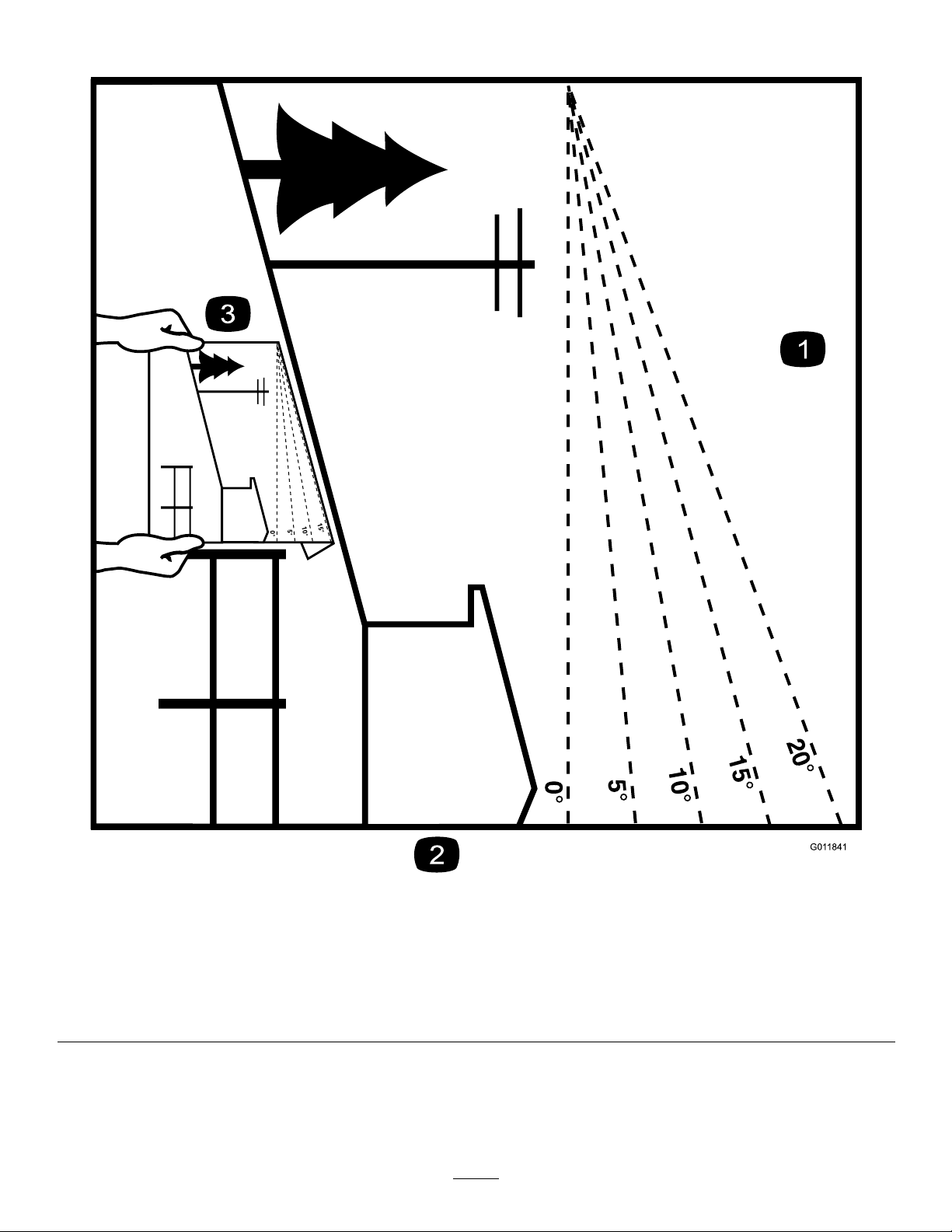
Figure3
Thispagemaybecopiedforpersonaluse.
1.Themaximumslopeyoucansafelyoperatethemachineonis20degrees.Usetheslopecharttodeterminethedegreeofslope
ofhillsbeforeoperating.Donotoperatethismachineonaslopegreaterthan20degrees.Foldalongtheappropriateline
tomatchtherecommendedslope.
2.Alignthisedgewithaverticalsurface,atree,building,fencepole,etc.
3.Exampleofhowtocompareslopewithfoldededge.
7
Page 8
SafetyandInstructionalDecals
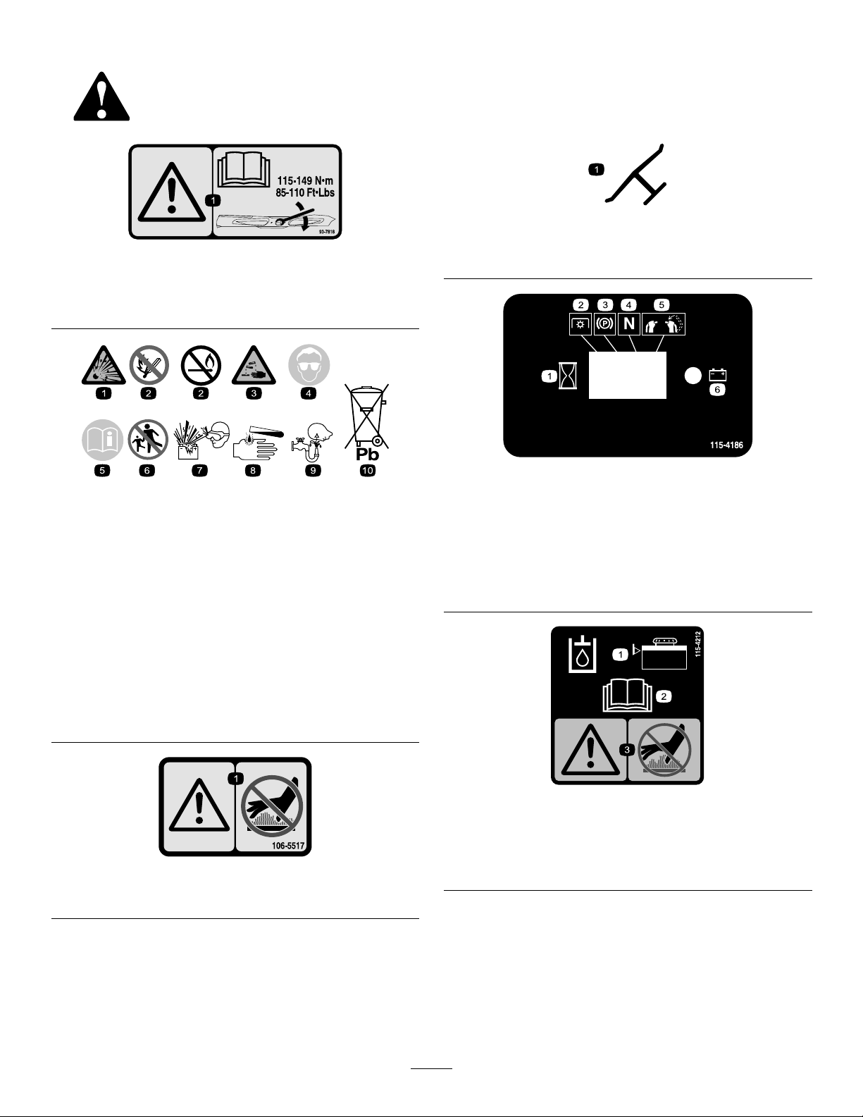
Safetydecalsandinstructionsareeasilyvisibletotheoperatorandarelocatednearanyareaofpotential
danger.Replaceanydecalthatisdamagedorlost.
Manufacturer'sMark
93-7818
1.Warning—readtheOperator'sManualforinstructionson
torquingthebladebolt/nutto1 15to149N-m(85to110
ft-lb).
BatterySymbols
Someorallofthesesymbolsareonyourbattery
1.Explosionhazard
2.Nore,opename,or
smoking.
3.Causticliquid/chemical
burnhazard
4.Weareyeprotection9.Flusheyesimmediately
5.ReadtheOperator's
Manual.
6.Keepbystandersasafe
distancefromthebattery.
7.Weareyeprotection;
explosivegasescan
causeblindnessandother
injuries
8.Batteryacidcancause
blindnessorsevereburns.
withwaterandgetmedical
helpfast.
10.Containslead;donot
discard.
1.Indicatesthebladeisidentiedasapartfromtheoriginal
machinemanufacturer.
115-4186
1.Interval
2.PowerTake-off(PTO)
3.Parkingbrake
4.Neutral
5.Operatorpresenceswitch
6.Battery
1.Warning—donottouchthehotsurface.
115-4212
1.Hydraulicoillevel3.Warning—donottouchthe
106-5517
2.ReadtheOperator's
Manual.
hotsurface.
8
Page 9
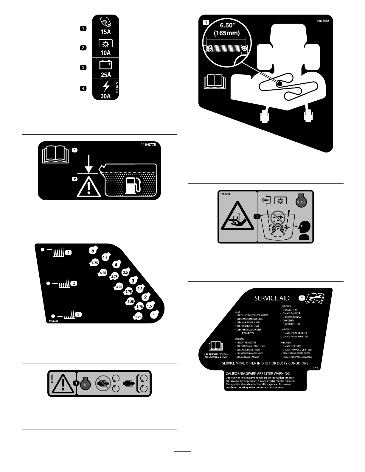
116-8772
1.Accessory,15A
2.PTO,10A
1.ReadtheOperator’s
Manual.
3.Charge,25A
4.Main,30A
120-6412
1.Belttensionadjustment;readtheOperator'sManualfor
moreinformation.
116-8775
2.Filltobottomofllerneck;
warning—Donotoverll
thetank.
120-6424
1.Cutting/dismembermenthazard,hand—disengagethe
powertake-off(PTO),stoptheengineandwatchforall
movingpartstostop.
117-0456
1.Heightofcut(HOC)—high3.Heightofcut(HOC)—low
2.Heightofcut
(HOC)—medium
119-0217
1.Warning—stoptheengine;stayawayfrommovingparts;
keepallguardsandshieldsinplace.
121-5972
1.ReadtheOperator’sManualbeforeservicingorperforming
maintenance.
9
Page 10
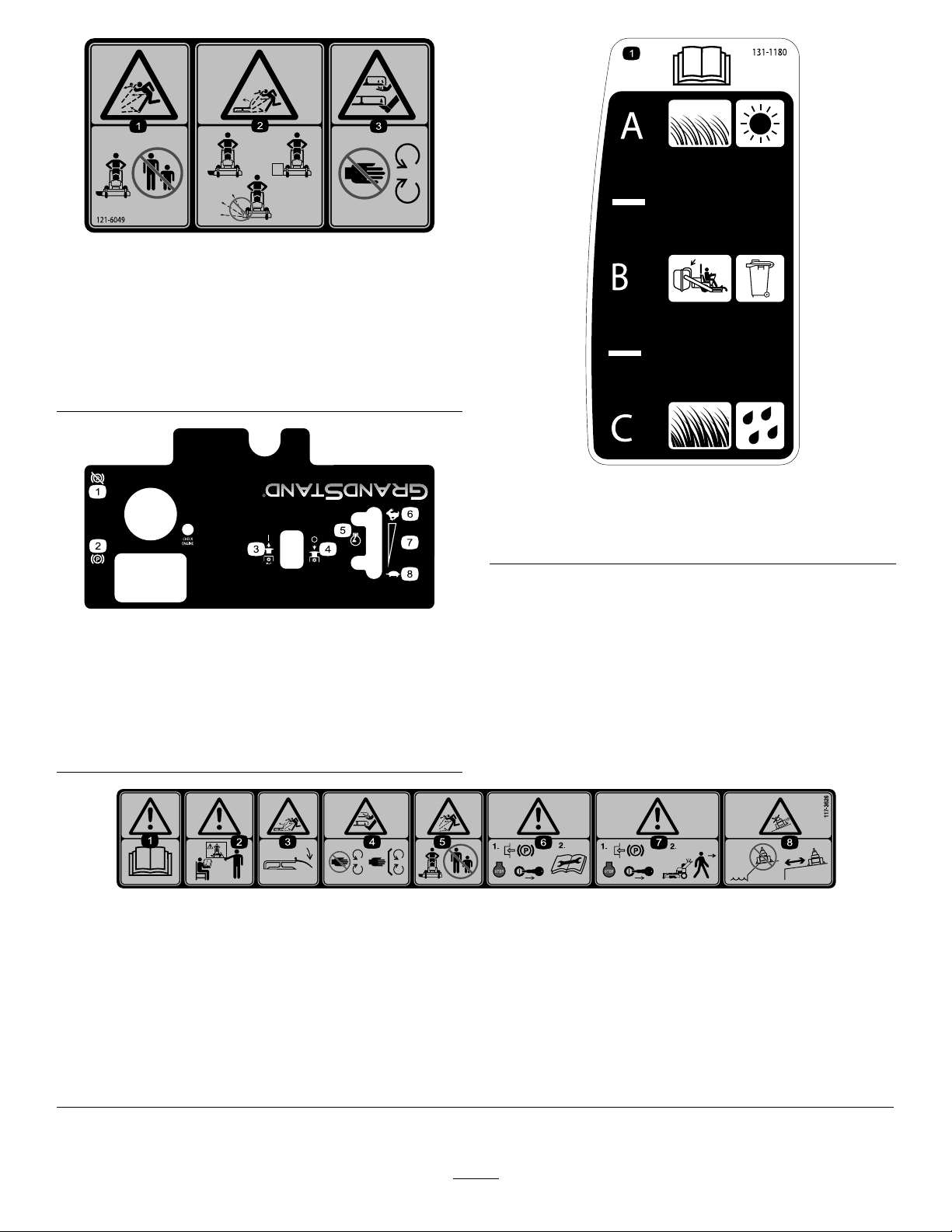
121-6049
1.Thrownobject
hazard—keepbystanders
awayfromthemachine.
2.Thrownobjecthazard,
mower—donotoperate
themowerwithguardsor
shieldsremoved.
3.Cutting/dismemberment
120-6497
1.Parkingbrake—disengage5.Enginespeed
2.Parkingbrake—engage6.Fast
3.PowerTake-off
(PTO)—engage
4.PowerTake-off
(PTO)—disengage
7.Continuousvariable
8.Slow
hazardofhandorfoot,
mowerblade—keephands
awayfrommovingparts.
131-1180
1.ReadtheOperator'sManual.(A)Short,lightgrass;dry
conditions;maximumdispersion;(B)Baggingsetting;(C)
Tall,densegrass;wetconditions;maximumgroundspeed
setting
117-3626
1.Warning—readtheOperator'sManual.5.Thrownobjecthazard—keepbystandersasafedistancefrom
2.Warning—donotoperatethismachineunlessyouaretrained.6.Warning—engagetheparkingbrake,stoptheengine
3.Thrownobjecthazard—keepdeectorinplace.
4.Cutting,dismembermenthazardofhandorfoot—stayaway
frommovingpartsandkeepallguardsandshieldsinplace.
themachine.
andremovethesparkplugwirebeforeperformingany
maintenanceonthemachine.
7.Warning—engagetheparkingbrakeandstoptheengine
beforeleavingthemachine.
8.Slidingandlossofcontrolhazard—donotoperatethe
machineneardrop-offsorwater;keepasafedistancefrom
drop-offs.
10
Page 11

119-8727
1.Tractioncontrol
2.Fast4.Neutral
3.Slow
5.Reverse
6.PowerTake-off
(PTO)—disengage
7.Operatorpresenceswitch
11
Page 12
ProductOverview
g020878
10
g017733
3
4
5
6
7
8
9
10
11
12
13
Controls
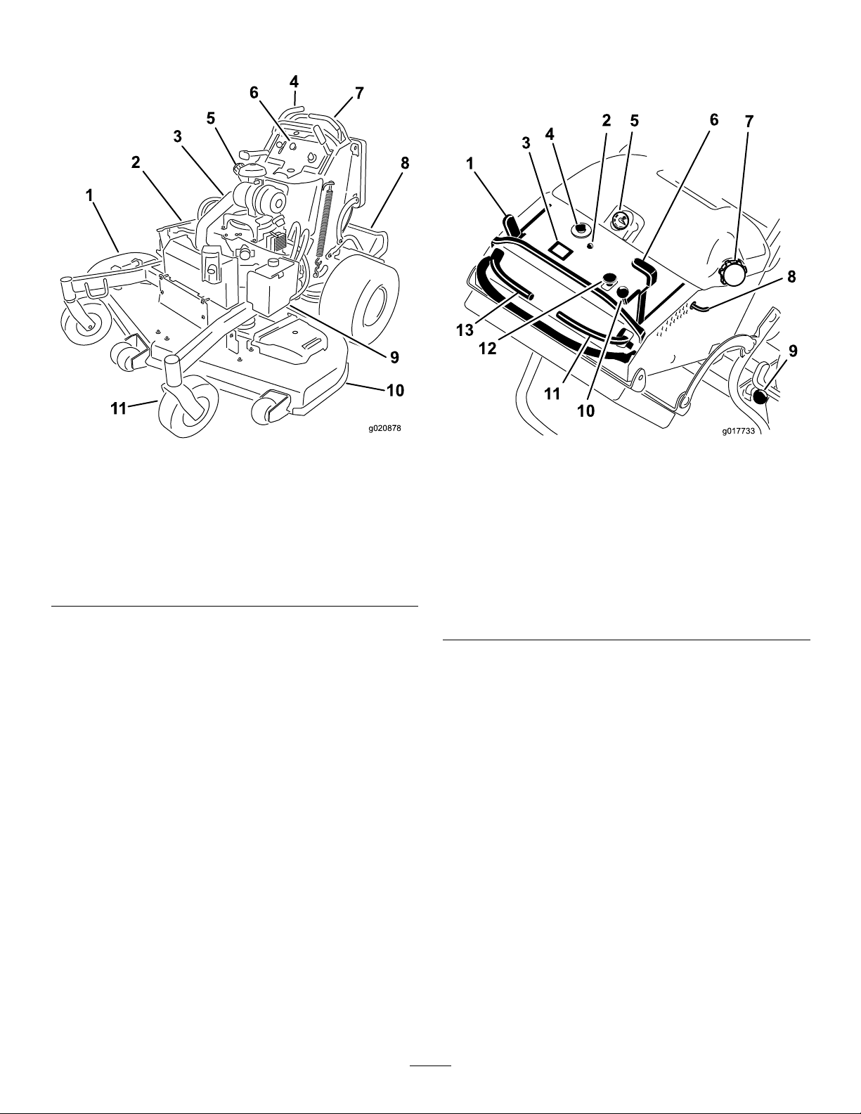
Becomefamiliarwithallthecontrols(Figure5)beforeyou
starttheengineandoperatethemachine.
Figure4
1.Side-dischargechute7.Controllevers
2.Battery
3.Engine9.Hydraulictank
4.Fuelshut-offvalve(behind
cushion)
5.Fueltank11.Frontcasterwheel
6.Controls
8.Platform(downposition)
10.Mowerdeck
Figure5
1.Parking-brakelever
2.Malfunction-indicatorlight
(MIL)
3.Hourmeter10.Throttlecontrol
4.Ignitionswitch11.Rightmotion-controllever
5.Fuelgauge12.Blade-controlswitch
6.Height-of-cutlever13.Leftmotion-controllever
7.Fuelcap
8.Height-of-cutpin
9.Platformlatch
(PTO)
HourMeter
Thehourmeterrecordsthenumberofhourstheenginehas
operated.Itoperateswhentheengineisrunning.Usethese
timesforschedulingregularmaintenance(Figure5).
FuelGauge
Thefuelgaugeislocatedonthetop,middleofthetank
(Figure5).
Safety-InterlockIndicators
Symbolsonthehourmeterindicatewithablacktrianglethat
theinterlockcomponentisinthecorrectposition(Figure6).
Battery-IndicatorLight
IftheignitionkeyisturnedtotheOnpositionforafew
seconds,thebatteryvoltagewillbedisplayedinthearea
wherethehoursarenormallydisplayed.
12
Page 13

Thebatterylightturnsonwhentheignitionisturnedonand
whenthechargeisbelowthecorrectoperatinglevel(Figure
6).
Motion-ControlLevers
Themotion-controlleversareusedtodrivethemachine
forward,reverse,andturneitherdirection.
FuelShut-offValve
Closethefuelshut-offvalve(locatedbehindtheoperator
cushionontheright-handsideofthefueltank)when
transportingorstoringthemower.
Attachments/Accessories
Figure6
1.Safety-interlocksymbols
2.Batterylight
3.Hourmeter
ThrottleControl
ThethrottlecontrolisvariablebetweenFastandSlow.
Electronic-ControlUnit
Malfunction-IndicatorLight
Theelectronic-controlunit(ECU)continuouslymonitorsthe
operationoftheEFIsystem.
Ifaproblemorfaultwithinthesystemisdetected,the
malfunction-indicatorlight(MIL)isilluminated.
TheMIListheredlightlocatedintheconsolepanel.
OncetheMILilluminates,initialtroubleshootingchecks
shouldbemade.
Ifthesechecksdonotcorrecttheproblem,furtherdiagnosis
andservicingbyanAuthorizedServiceDealerisnecessary.
AselectionofToroapprovedattachmentsandaccessoriesis
availableforusewiththemachinetoenhanceandexpand
itscapabilities.ContactyourAuthorizedServiceDealeror
Distributororgotowww .Toro.comforalistofallapproved
attachmentsandaccessories.
Choke
Usethechoketostartacoldengine.
Blade-ControlSwitch(PTO)
Theblade-controlswitch(PTO)isusedtoengagethe
electricclutchtodrivethemowerbladeswiththerightside
motion-controlleverinthecenter,unlockedposition.Pull
theswitchuptoengagethebladesandrelease.Todisengage
theblades,pushtheblade-controlswitch(PTO)downor
moveorreleasetherightsidemotion-controlleverintothe
neutral-lockposition.
IgnitionSwitch
Thisswitchisusedtostartthemowerengineandhasthree
positions:Off,RunandStart.
13
Page 14
Specications
Note:Specicationsanddesignaresubjecttochange
withoutnotice.
48-inchMowers
Operation
Note:Determinetheleftandrightsidesofthemachine
fromthenormaloperatingposition.
Widthwithdeectordown161.3cm(63.5inches)
Widthwithdeectorraised125.7cm(49.5inches)
Lengthwithplatformdown188cm(74inches)
Lengthwithplatformup149.9cm(59inches)
Height
Weightformodel74588412kg(909lbs)
121.9cm(48inches)
52-inchMowers
Widthwithdeectordown171.7cm(67.6inches)
Widthwithdeectorraised135.9cm(53.5inches)
Lengthwithplatformdown188cm(74inches)
Lengthwithplatformup149.9cm(59inches)
Height
Weightformodel74589413.7kg(912lbs)
Weightformodel79589416.4kg(918lbs)
121.9cm(48inches)
60-inchMowers
Widthwithdeectordown192.2cm(76inches)
Lengthwithplatformdown188cm(74inches)
Lengthwithplatformup147.3cm(58inches)
Height
Weightformodel74583420.9kg(928lbs)
121.9cm(48inches)
AddingFuel
•Forbestresults,useonlyclean,fresh(lessthan30days
old),unleadedgasolinewithanoctaneratingof87or
higher((R+M)/2ratingmethod).
•Ethanol:Gasolinewithupto10%ethanol(gasohol)
or15%MTBE(methyltertiarybutylether)byvolume
isacceptable.EthanolandMTBEarenotthesame.
Gasolinewith15%ethanol(E15)byvolumeisnot
approvedforuse.Neverusegasolinethatcontains
morethan10%ethanolbyvolume,suchasE15
(contains15%ethanol),E20(contains20%ethanol),or
E85(containsupto85%ethanol).Usingunapproved
gasolinemaycauseperformanceproblemsand/orengine
damagewhichmaynotbecoveredunderwarranty.
•Donotusegasolinecontainingmethanol.
•Donotstorefueleitherinthefueltankorfuelcontainers
overthewinterunlessafuelstabilizerisused.
•Donotaddoiltogasoline.
DANGER
Incertainconditions,gasolineisextremely
ammableandhighlyexplosive.Areorexplosion
fromgasolinecanburnyouandothersandcan
damageproperty.
•Fillthefueltankoutdoors,inanopenarea,
whentheengineiscold.Wipeupanygasoline
thatspills.
•Neverllthefueltankinsideanenclosedtrailer.
•Donotllthefueltankcompletelyfull.Add
gasolinetothefueltankuntilthelevelis6to13
mm(1/4to1/2inch)belowthebottomofthe
llerneck.Thisemptyspaceinthetankallows
gasolinetoexpand.
•Neversmokewhenhandlinggasoline,andstay
awayfromanopenameorwheregasoline
fumesmaybeignitedbyaspark.
•Storegasolineinanapprovedcontainerand
keepitoutofthereachofchildren.Neverbuy
morethana30-daysupplyofgasoline.
•Donotoperatewithoutentireexhaustsystemin
placeandinproperworkingcondition.
14
Page 15
DANGER
G009027
1
2
Incertainconditionsduringfueling,static
electricitycanbereleasedcausingasparkwhich
canignitethegasolinevapors.Areorexplosion
fromgasolinecanburnyouandothersandcan
damageproperty.
•Alwaysplacegasolinecontainersontheground
awayfromyourvehiclebeforelling.
•Donotllgasolinecontainersinsideavehicleor
onatruckortrailerbedbecauseinteriorcarpets
orplastictruckbedlinersmayinsulatethe
containerandslowthelossofanystaticcharge.
•Whenpractical,removegas-poweredequipment
fromthetruckortrailerandrefueltheequipment
withitswheelsontheground.
•Ifthisisnotpossible,thenrefuelsuch
equipmentonatruckortrailerfromaportable
container,ratherthanfromagasolinedispenser
nozzle.
•Ifagasolinedispensernozzlemustbeused,
keepthenozzleincontactwiththerimofthe
fueltankorcontaineropeningatalltimesuntil
fuelingiscomplete.
ofvarnishdepositsinthefuelsystem,usefuelstabilizer
atalltimes.
FillingtheFuelTank
1.Shuttheengineoffandsettheparkingbrake.
2.Cleanaroundthefueltankcapandremovethecap.
Addunleadedregulargasolinetothefueltank,untilthe
levelis6to13mm(1/4to1/2inch)belowthebottom
ofthellerneck.Thisspaceinthetankallowsthe
gasolinetoexpand.Donotllthefueltankcompletely
full.
3.Installthefueltankcapsecurely.Wipeupanygasoline
thatmayhavespilled.
CheckingtheEngine-OilLevel
Beforeyoustarttheengineandusethemachine,check
theoillevelintheenginecrankcase;refertoCheckingthe
Engine-OilLevel(page33).
BreakinginaNewMachine
Newenginestaketimetodevelopfullpower.Mowerdecks
anddrivesystemshavehigherfrictionwhennew,placing
additionalloadontheengine.Allow40to50hoursof
break-intimefornewmachinestodevelopfullpowerand
bestperformance.
WARNING
Gasolineisharmfulorfatalifswallowed.Long-term
exposuretovaporscancauseseriousinjuryand
illness.
•Avoidprolongedbreathingofvapors.
•Keepfaceawayfromnozzleandgastankor
conditionerbottleopening.
•Avoidcontactwithskin;washoffspillagewith
soapandwater.
UsingStabilizer/Conditioner
Useafuelstabilizer/conditionerinthemachinetoprovide
thefollowingbenets:
•Keepsgasolinefreshduringstorageof90daysorless.
Forlongerstorageitisrecommendedthatthefueltank
bedrained.
•Cleanstheenginewhileitruns
•Eliminatesgum-likevarnishbuildupinthefuelsystem,
whichcauseshardstarting
Important:Donotusefueladditivescontaining
methanolorethanol.
ThinkSafetyFirst
Carefullyreadallthesafetyinstructionsanddecalsinthe
safetysection.Knowingthisinformationcouldhelpyouor
anybystandersavoidinjury.
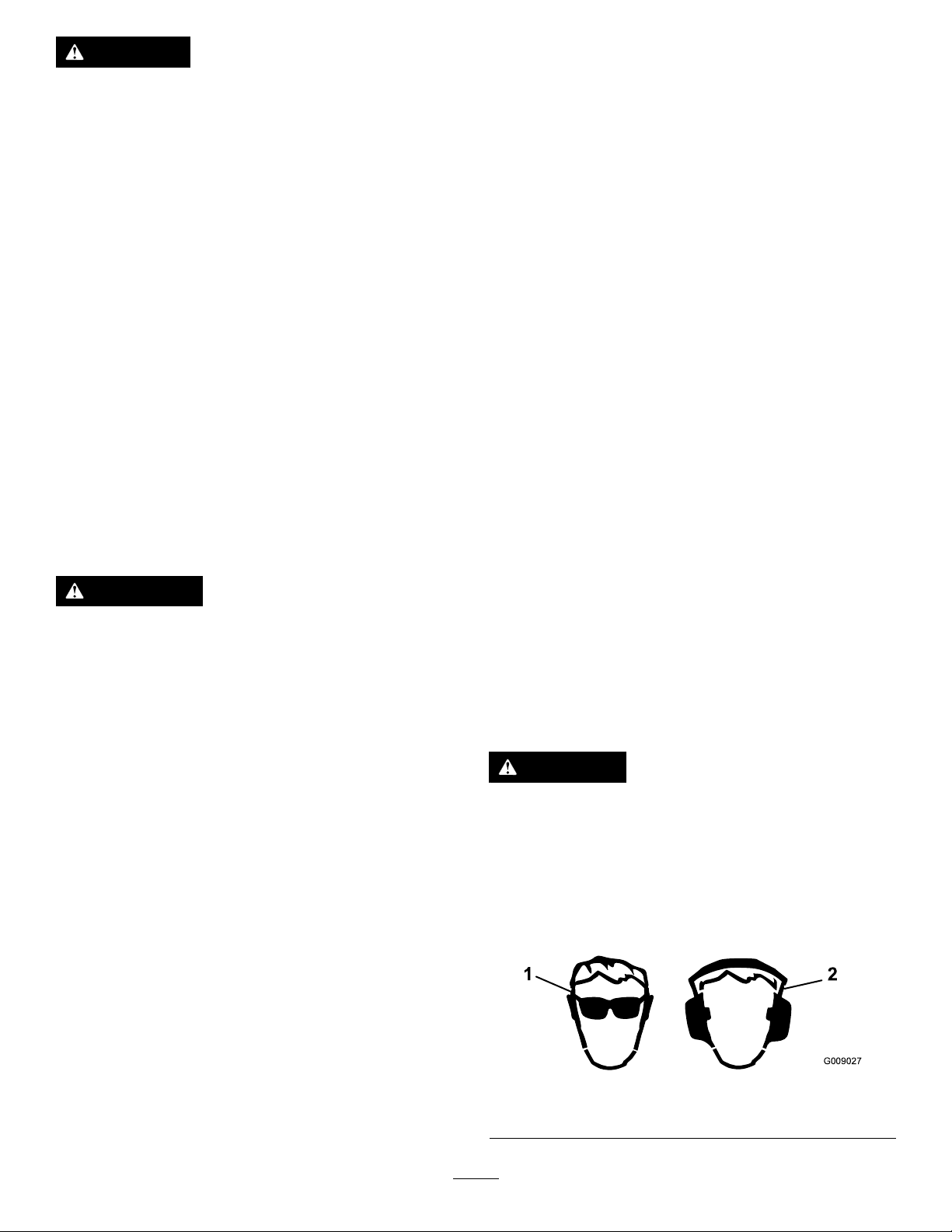
Theuseofprotectiveequipmentforeyes,hearing,feetand
headisrecommended.
CAUTION
Thismachineproducessoundlevelsinexcessof
85dBAattheoperator'searandcancausehearing
lossthroughextendedperiodsofexposure.
Wearhearingprotectionwhenoperatingthis
machine.
Theuseofprotectiveequipmentforeyes,ears,feet,andhead
isrecommended.
Addthecorrectamountofgasstabilizer/conditionerto
thegas.
Note:Afuelstabilizer/conditionerismosteffective
whenmixedwithfreshgasoline.T ominimizethechance
1.Wearsafetyglasses
15
Figure7
2.Wearhearingprotection
Page 16
OperatingtheParkingBrake
G008945
G009174
G008946
Alwayssettheparkingbrakewhenyoustopthemachineor
leaveitunattended.Beforeeachuse,checktheparkingbrake
forproperoperation.
Iftheparkingbrakedoesnotholdsecurely,adjustit;referto
ServicingtheBrake(page47).
CAUTION
Childrenorbystandersmaybeinjuredifthey
moveorattempttooperatethemachinewhileitis
unattended.
Alwaysremovetheignitionkeyandsettheparking
brakewhenleavingthemachineunattended,even
ifjustforafewminutes.
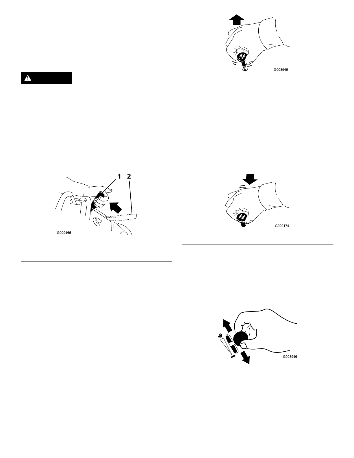
SettingtheParkingBrake
Pulltheparkingbrakeleverrearwardandoverintoengaged
position(Figure8).
Figure8
Figure9
DisengagingtheMowerBlades(PTO)
Thefollowingaretwooptionsfordisengagingthemower
blades.
•Pushtheblade-controlswitch(PTO)downtotheOff
position.
•Movethemotion-controlleverstoneutralandmove
therightsidemotion-controlleverintotheneutral-lock
position.
Figure10
1.Parkingbrakeengaged2.Parkingbrakereleased
ReleasingtheParkingBrake
Pullthebrakeleverbackandoverintotheslotandpushthe
parkingbrakeleverforward.
Operatingthe Mower-Blade-ControlSwitch (PTO)
Theblade-controlswitch(PTO)isusedinconjunctionwith
therightsidemotion-controllevertoengageanddisengage
themowerblades.
EngagingtheMowerBlades(PTO)
1.Toengagethemowerblades,movetherightside
motion-controllevertothecenter,unlockedposition.
2.Pulltheblade-controlswitch(PTO)upandreleaseit
whileholdingdowntherightsidemotion-controllever
inthecenter,unlockedposition.
OperatingtheThrottle
ThethrottlecontrolmovesbetweenFastandSlowpositions
(Figure11).
AlwaysusetheFastpositionwhenturningonthemower
deckwiththeblade-controlswitch(PTO).
Figure11
16
Page 17
OperatingtheIgnitionSwitch
START
RUN
STOP
G008947
g017735
G008948
1
2
UsingtheFuelShut-offValve
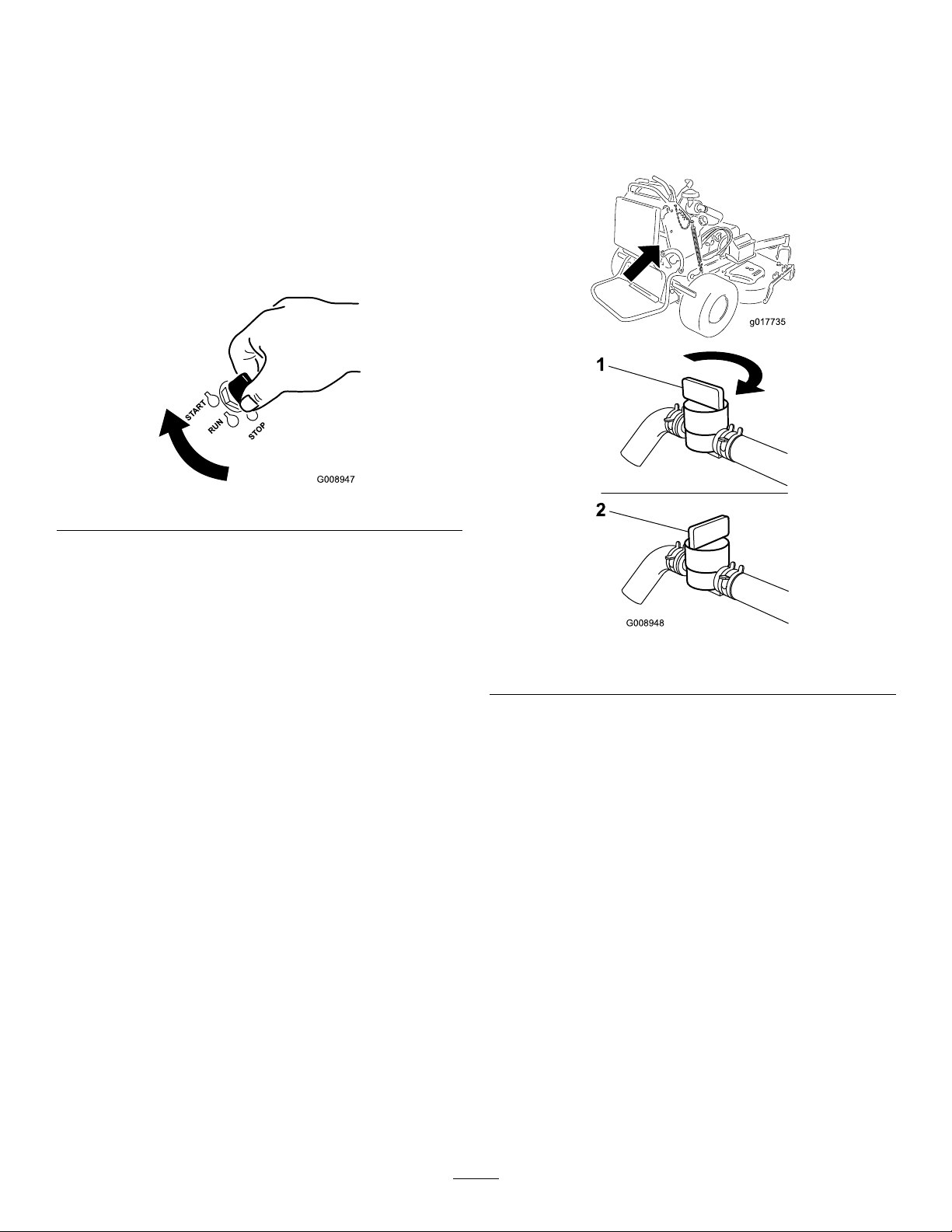
1.TurntheignitionkeytotheStartposition(Figure12).
Whentheenginesstarts,releasethekey .
Important:Donotengagethestarterformore
than5secondsatatime.Iftheenginefailsto
start,allowa15secondcool-downperiodbetween
attempts.Failuretofollowtheseinstructionscan
burnoutthestartermotor.
Note:Additionalstartingcyclesmayberequired
whenstartingtheengineforthersttimeafterthefuel
systemhasbeenwithoutfuelcompletely.
Figure12
Closethefuelshut-offvalvefortransport,maintenance,and
storage(Figure13).
Ensurethatthefuelshut-offvalveisopenwhenstartingthe
engine.
2.Turntheignitionkeytostoptoturnofftheengine.
Figure13
1.Onposition2.Offposition
StartingandStoppingthe Engine
StartingtheEngine
1.Connectthewirestothesparkplugs.
2.Openthefuelvalve.
3.Movetherightmotion-controllevertoneutrallocked
position.
4.Settheparkingbrake;refertoSettingtheParking
Brake.
5.Movetheblade-controlswitch(PTO)totheOff
position.
6.MovethethrottlelevermidwaybetweentheSlowand
Fastpositions.
17
Page 18
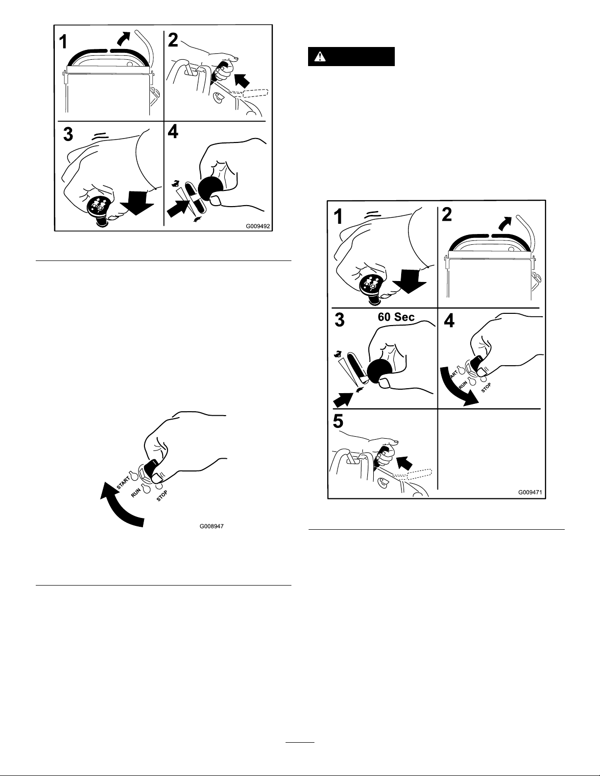
Figure14
START
RUN
STOP
G008947
7.TurntheignitionkeytotheStartposition(Figure12).
Whentheenginesstarts,releasethekey .
Important:Donotengagethestarterformore
than5secondsatatime.Iftheenginefailsto
start,allowa15secondcool-downperiodbetween
attempts.Failuretofollowtheseinstructionscan
burnoutthestartermotor.
StoppingtheEngine
CAUTION
Childrenorbystandersmaybeinjuredifthey
moveorattempttooperatethetractorwhileitis
unattended.
Alwaysremovetheignitionkeyandsettheparking
brakewhenleavingthemachineunattended,even
ifjustforafewminutes.
Lettheengineidleatslowthrottle(turtle)for60seconds
beforeturningtheignitionswitchoff.
Note:Additionalstartingcyclesmayberequired
whenstartingtheengineforthersttimeafterthefuel
systemhasbeenwithoutfuelcompletely.
Figure15
1.Offposition3.Startposition
2.Runposition
Figure16
Important:Makesurethefuelshut-offvalveisclosed
beforetransportingorstoringthemachine,asfuel
leakagemayoccur.Beforestoringthemachine,pull
wireoffsparkplug(s)topreventpossibilityofaccidental
starting.
18
Page 19
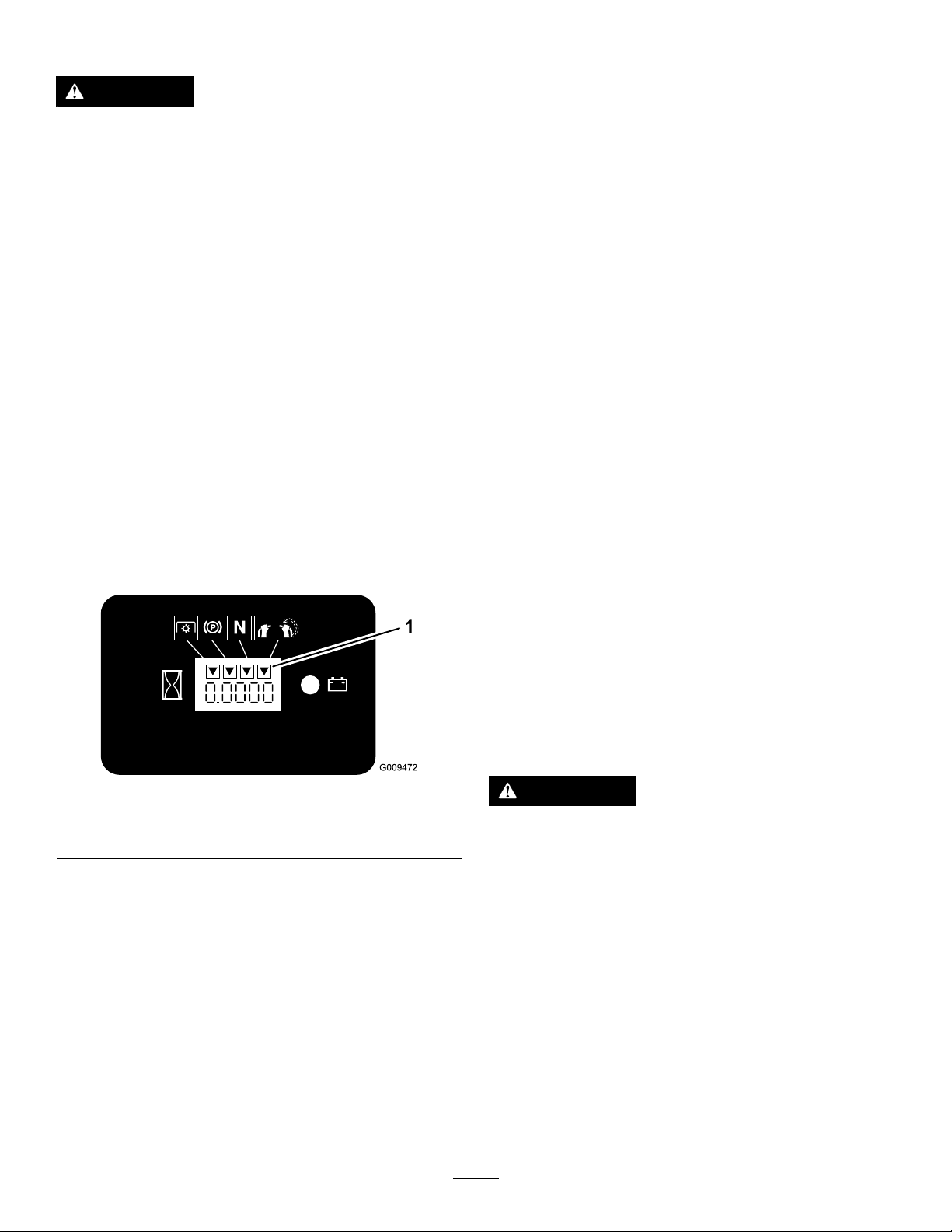
TheSafety-InterlockSystem
CAUTION
Ifsafety-interlockswitchesaredisconnectedor
damagedthemachinecouldoperateunexpectedly
causingpersonalinjury.
•Donottamperwiththeinterlockswitches.
•Checktheoperationoftheinterlockswitches
dailyandreplaceanydamagedswitchesbefore
operatingthemachine.
UnderstandingtheSafety-Interlock
System
Thesafety-interlocksystemisdesignedtopreventthemower
bladesfromrotatingunless:
•Therightsidemotion-controlleverismovedtothe
center,unlockedposition.
•Theblade-controlswitch(PTO)ispulledon.
Thesafety-interlocksystemisdesignedtostopthemower
bladesifyoumoveorreleasetherightsidemotion-control
leverintotheneutral-lockposition.
Thehourmeterhassymbolstonotifytheuserwhenthe
interlockcomponentisinthecorrectposition.Whenthe
componentisinthecorrectposition,atrianglewilllight
upinthecorrespondingsquare.
Note:Thebladesshouldnotrotate.
4.Movethemotion-controlleversforward.
Note:Theengineshouldstoprunning.
5.Starttheengineandreleasetheparkingbrake.
6.Movetherightsidemotion-controllevertothecenter,
unlockedposition.
7.Continueholdingtherightsidemotion-controllever
inthecenter,unlockedposition,pulluponthe
blade-controlswitch(PTO),andrelease.
Note:Theclutchshouldengageandthemower
bladesrotate.
8.Moveorreleasetherightsidemotion-controlleverinto
theneutral-lockposition.
Note:Thebladesshouldstoprotatingandtheengine
continuestorun.
9.Pushtheblade-controlswitchdownandmovethe
rightsidemotion-controllevertothecenter,unlocked
position.
10.Continueholdingtherightsidemotion-controllever
inthecenter,unlockedposition,pulluponthe
blade-controlswitch(PTO),andrelease.
Note:Theclutchshouldengageandthemower
bladesrotate.
11.Pushtheblade-controlswitch(PTO)downtotheOff
position.
Figure17
1.Triangleslightupwhentheinterlockcomponentsareinthe
correctposition
TestingtheSafety-InterlockSystem
ServiceInterval:Beforeeachuseordaily
Testthesafety-interlocksystembeforeyouusethemachine
eachtime.
Note:Ifthesafetysystemdoesnotoperateasdescribed
below,haveanAuthorizedServiceDealerrepairthesafety
systemimmediately.
1.Starttheengine;refertoStartingtheEngine(page17).
2.Settheparkingbrake.
3.Movetherightsidemotion-controllevertothecenter,
unlockedposition.
Note:Thebladesshouldstoprotating.
12.Withtheenginerunning,pulluptheblade-control
switch(PTO)andreleaseitwithoutholdingrightside
motion-controllevertothecenter,unlockedposition.
Note:Thebladesshouldnotrotate.
WARNING
Theoperatorplatformisheavyandmaycause
injurywhenloweringandraising.Theplatform
maysuddenlydropifnotsupportedwhenthelatch
pinispulledout.
•Donotputyourhandsorngersinthe
platform-pivotareawhenloweringorraisingthe
operatorplatform.
•Makesuretheplatformissupportedwhenthe
latchpinispulledout.
•Makesurethelatchsecurestheplatformwhen
foldingitintheupposition.Pushittightagainst
thecushionforthelatchpintolockintoplace.
•Keepbystandersawaywhenraisingorlowering
theplatform.
19
Page 20
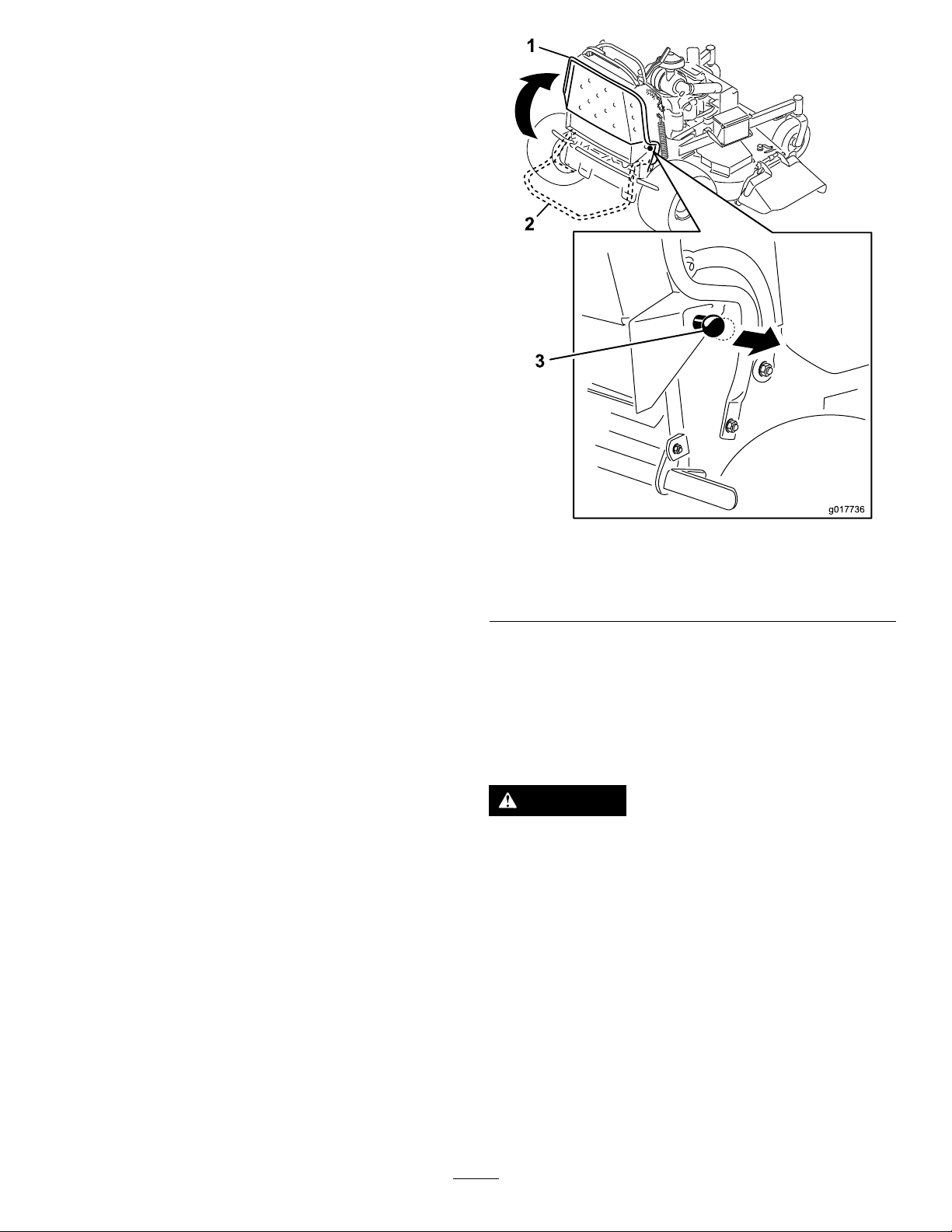
OperatingthePlatform
g017736
1
2
3
Themachinecanbeusedwiththeplatformintheupordown
position.Itistheoperator'spreferenceonwhichposition
touse.
OperatingtheMachinewiththe
PlatformUp
Operatingthemachinewiththeplatformupisrecommended
forthefollowing:
•Mowingneardrop-offs
•Mowingsmallareaswherethemachineistoolarge
•Areaswithlow ,over-hangingbranchesorobstacles
•Loadingthemachinefortransport
•Drivingupslopes
Toraisetheplatform,pullthebackoftheplatformupsothat
thelatchpinandknoblockitintoplace.Pushittightagainst
thecushionforthelatchpintolockitintoplace.
OperatingtheMachinewiththe
PlatformDown
Operatingthemachinewiththeplatformdownis
recommendedforthefollowing:
•Mowingmostareas
1.Platformup
2.Platformdown
Figure18
3.Pulltheknobouttorelease
theplatform.
•Drivingacrossslopes
•Drivingdownslopes
Tolowertheplatform,pushtheplatformforwardagainstthe
cushiontoreleasepressureonthelatchpin,thenpullthe
knobout,andlowertheplatform(Figure18).
DrivingForwardorBackward
Thethrottlecontrolregulatestheenginespeedasmeasured
inrpm(revolutionsperminute).Placethethrottlecontrolin
theFastpositionforbestperformance.Alwaysoperatethe
machineinthefullthrottlepositionwhenmowing.
CAUTION
Themachinecanspinveryrapidly.Theoperator
maylosecontrolofmachine,andmaycause
personalinjuryordamagetomachine.
Slowthemachinedownbeforemakingsharpturns.
20
Page 21
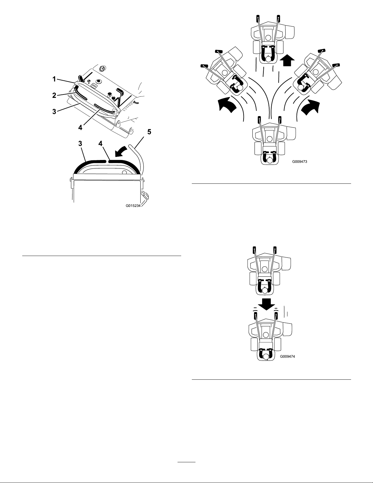
DrivingForward
G015234
4
5
1
2
3
3 4
1.Releasetheparkingbrake;refertoReleasingthe
ParkingBrake(page16).
2.Movetherightsidemotion-controllevertothecenter,
unlockedposition.
Figure20
DrivingBackward
Figure19
1.Frontreferencebar
2.Leftcontrollever
3.Rearreferencebar
4.Rightcontrollever
5.Rightcontrolleverinthe
neutrallockposition
3.Togoforward,movethespeed-controllevertothe
desiredspeed.
4.Slowlypushthemotion-controlleversforward(Figure
20).
Note:Theenginewillkillifamotion-controlleveris
movedwiththeparkingbrakeengaged.
Note:Thefartheryoumovethemotion-controllevers
ineitherdirection,thefasterthemachinewillmove
inthatdirection.
Note:Tostop,pullthemotion-controlleversbackto
theneutralposition.
1.Movetherightsidemotion-controllevertothecenter,
unlockedposition.
2.Slowlypullthemotion-controlleversrearward(Figure
21).
Figure21
21
Page 22
StoppingtheMachine
G017978
1
1 2
1
PushingtheMachinebyHand
Tostopthemachine,movethemotion-controlleversto
neutral,movetherightsidemotion-controlleverintothe
neutral-lockposition,disengagethepower-takeoff(PTO),
andturntheignitionkeytotheOffposition.
Settheparkingbrakewhenyouleavethemachine;referto
SettingtheParkingBrake(page16).Remembertoremove
thekeyfromtheignitionswitch.
CAUTION
Childrenorbystandersmaybeinjuredifthey
moveorattempttooperatethetractorwhileitis
unattended.
Alwaysremovetheignitionkeyandsettheparking
brakewhenleavingthemachineunattended,even
ifjustforafewminutes.
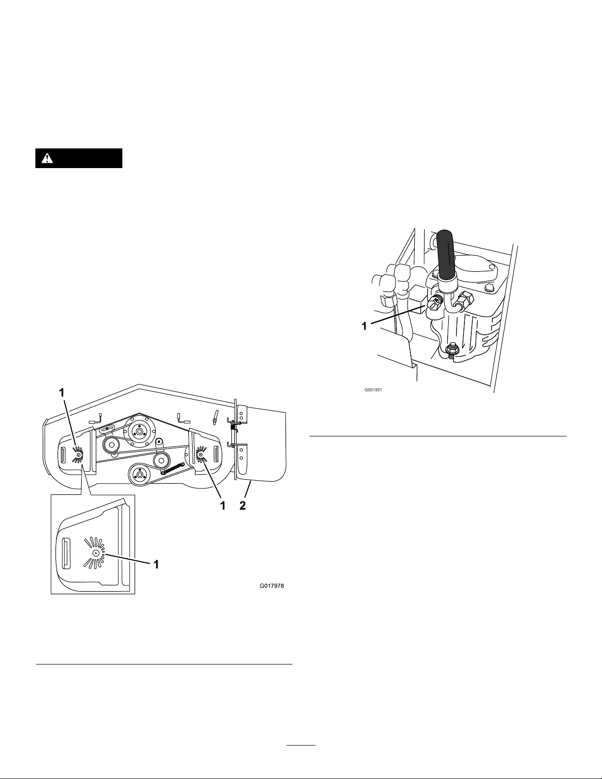
UsingtheRotationIndicator
Theslotsinthetopofthebeltcoversallowtheoperatorto
verifyifthebladeshavestoppedrotatingafterdisengagingthe
powertake-off(PTO)switch.
Thebypassvalvesallowthemachinetobepushedbyhand
withouttheenginerunning.
Important:Alwayspushthemachinebyhand.Donot
towthemachine,becausehydraulicdamagemayoccur.
1.DisengagethePTO ,movethemotion-controlleversto
theneutral-lockedpositionandsettheparkingbrake.
2.Openthebypassvalveonbothpumpsbyturningthem
counterclockwise1to2turns.Thisallowshydraulic
uidtobypassthepumpsandthewheelstoturn
(Figure23).
Note:Rotatethebypassvalvesamaximumof2turns
sothevalvedoesnotcomeoutofthebodycausing
uidtorunout.
Disengagethepowertake-off(PTO)switch,stoptheengine,
removethekey,andwaitforallmovingpartstostopbefore
leavingtheoperatingposition.
Figure22
52-inchmowerdeckshown
1.RotationIndicator—slots
inthetopofthebeltcover
2.Side-dischargechute
Figure23
1.Pump-bypassvalve
3.Releasetheparkingbrake.
4.Pushthemachinetothedesiredlocation.
5.Settheparkingbrake.
6.Closethebypassvalves,butdonotovertightenthem.
Torqueto12to15N-m(9to11ft-lb).
Important:Donotstartoroperatethemachine
withthebypassvalvesopen.Damagetosystem
mayoccur.
TransportingtheMachine
Useaheavy-dutytrailerortrucktotransportthemachine.
Ensurethatthetrailerortruckhasallthenecessarybrakes,
lighting,andmarkingasrequiredbylaw .Pleasecarefullyread
allthesafetyinstructions.
Totransportthemachine:
1.Raisetheplatformofthemachinebeforedrivingonto
thetrailerortruck.
2.Ifusingatrailer,connectittothetowingvehicleand
connectthesafetychains.
22
Page 23
3.Ifapplicable,connectthetrailerbrakes.
g017737
1
4.Loadthemachineontothetrailerortruck.
5.Stoptheengine,removethekey,setthebrake,and
closethefuelvalve.
WARNING
Loadingaunitontoatrailerortruckincreasesthe
possibilityofbackwardtip-over,andcouldcause
seriousinjuryordeath.
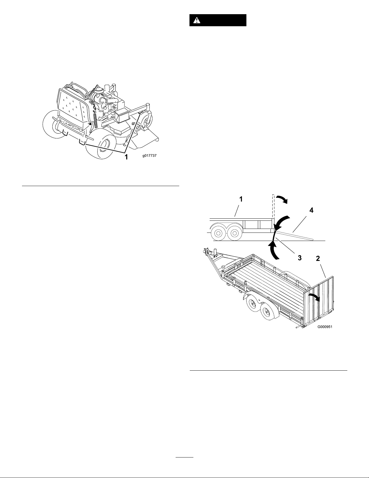
6.Usethemetaltie-downloopsonthemachineto
securelyfastenthemachinetothetrailerortruckwith
straps,chains,cable,orropes(Figure24).
Figure24
1.Tractionunittie-downloop
LoadingtheMachine
Useextremecautionwhenloadingunitsontotrailersor
trucks.Onefull-widthrampthatiswideenoughtoextend
beyondthereartiresisrecommendedinsteadofindividual
rampsforeachsideoftheunit(Figure25).Theplatform
whendownandlockedintoposition,extendsbackbetween
therearwheelsandservesasastopfortippingbackward.
Havingafull-widthrampprovidesasurfacefortheplatform
tocontactiftheunitstartstotipbackward.Withtheplatform
up,afull-widthrampprovidesasurfacetowalkonbehindthe
unit.Theoperatorshoulddetermineifitisbesttohavethe
platformupordownwhenloading,dependingonconditions.
Ifitisnotpossibletouseonefull-widthramp,useenough
individualrampstosimulateafull-width,continuousramp.
•Useextremecautionwhenoperatingauniton
aramp.
•Useonlyasingle,full-widthramp;donotuse
individualrampsforeachsideoftheunit.
•Ifindividualrampsmustbeused,useenough
rampstocreateanunbrokenrampsurfacewider
thantheunit.
•Donotexceeda20-degreeanglebetweenramp
andground,orbetweenaramp,atrailer,ora
truck.
•Avoidsuddenaccelerationwhiledrivingunitup
aramptoavoidtippingbackward.
•Avoidsuddendecelerationwhilebackingunit
downaramptoavoidtippingbackward.
Therampshouldbelongenoughsothattheanglesdonot
exceed20degrees(Figure25).Asteeperanglemaycause
mowercomponentstogetcaught,astheunitmovesfrom
ramptotrailerortruck.Steeperanglesmayalsocausethe
unittotipbackward.Ifloadingonornearaslope,position
thetrailerortrucksoitisonthedownsideoftheslopeand
therampextendsuptheslope.Thiswillminimizetheramp
angle.Thetrailerortruckshouldbeaslevelaspossible.
Important:Donotattempttoturntheunitwhileonthe
ramp;youmaylosecontrolanddriveofftheside.
Avoidsuddenaccelerationwhendrivinguparampand
suddendecelerationwhenbackingdownaramp.Both
maneuverscancausetheunittotipbackward.
Figure25
1.Trailer3.Notgreaterthan
2.Full-widthramp
20degrees
4.Full-widthramp(sideview)
SideDischargingorMulching theGrass
Thismowerhasahingedgrassdeectorthatdisperses
clippingstothesideanddowntowardtheturf.
23
Page 24
DANGER
g019208
g018324
AdjustingtheAnti-Scalp
Withoutthegrassdeector,dischargecover,or
completegrasscatcherassemblymountedin
place,youandothersareexposedtobladecontact
andthrowndebris.Contactwithrotatingmower
blade(s)andthrowndebriswillcauseinjuryor
death.
•Donotremovethegrassdeectorfrom
themower,becausethegrassdeector
routesmaterialdowntowardtheturf.Ifthe
grassdeectoriseverdamaged,replaceit
immediately.
•Neverputyourhandsorfeetunderthemower.
•Nevertrytoclearthedischargeareaormower
bladesunlessyoureleasethebailandthepower
takeoff(PTO)isoff.Rotatetheignitionkeyto
theOffposition.Alsoremovethekeyandpull
thewire(s)offthesparkplug(s).
AdjustingtheHeight-of-Cut
Theheight-of-cutcanbeadjustedfrom25to127mm(1to5
inches)in6mm(1/4inches)increments.
Rollers(for60-inchmodels
only)
Wheneveryouchangetheheight-of-cut,itisrecommended
toadjusttheheightoftheanti-scalprollers.
1.Disengagetheblade-controlswitch(PTO),movethe
motion-controlleverstotheneutral-lockedposition
andsettheparkingbrake.
2.Stoptheengine,removethekey,andwaitforallmoving
partstostopbeforeleavingtheoperatingposition.
3.Removethenutandboltpositiontheanti-scalprollers
andinstallthenutandbolt.
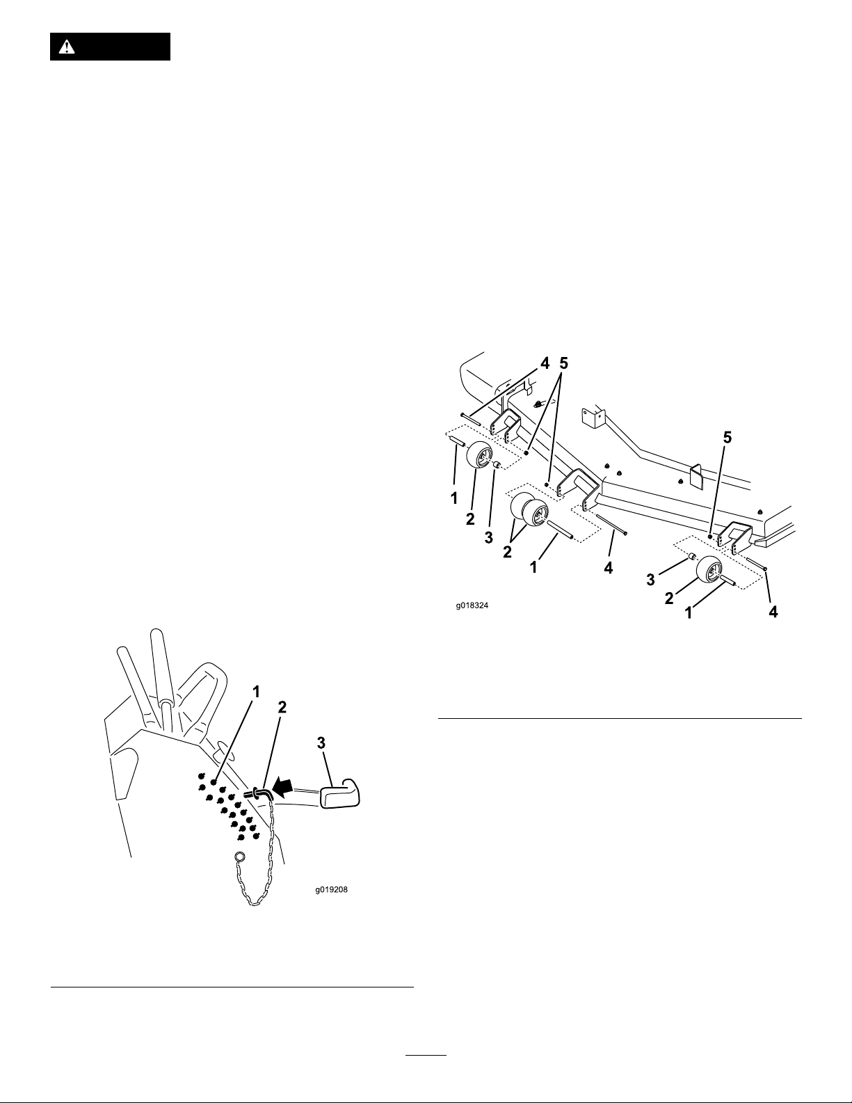
4.Ensurethespacersandbushingsareinstalled(Figure
27).
1.Movetheheight-of-cutlevertothetransportposition
(allthewayup).
2.Selectaholeintheheight-of-cutbracketcorresponding
totheheight-of-cutdesiredand,insertthepin(Figure
26).
3.Lowertheheight-of-cutlevertothepin(Figure26).
Figure26
1.Height-of-cutholes3.Height-of-cutlever
2.Height-of-cutpin
Figure27
1.Bushing4.Bolt
2.Anti-scalproller5.Nut
3.Spacer
AdjustingtheFlowBafe
Themower-dischargeowcanbeadjustedfordifferenttypes
ofmowingconditions.Positionthecamlockandbafeto
providethebestqualityofcut.
1.DisengagethePTO ,movethemotion-controlleversto
theneutral-lockedposition,andsettheparkingbrake.
2.Stoptheengine,removethekey,andwaitforallmoving
partstostopbeforeleavingtheoperatingposition.
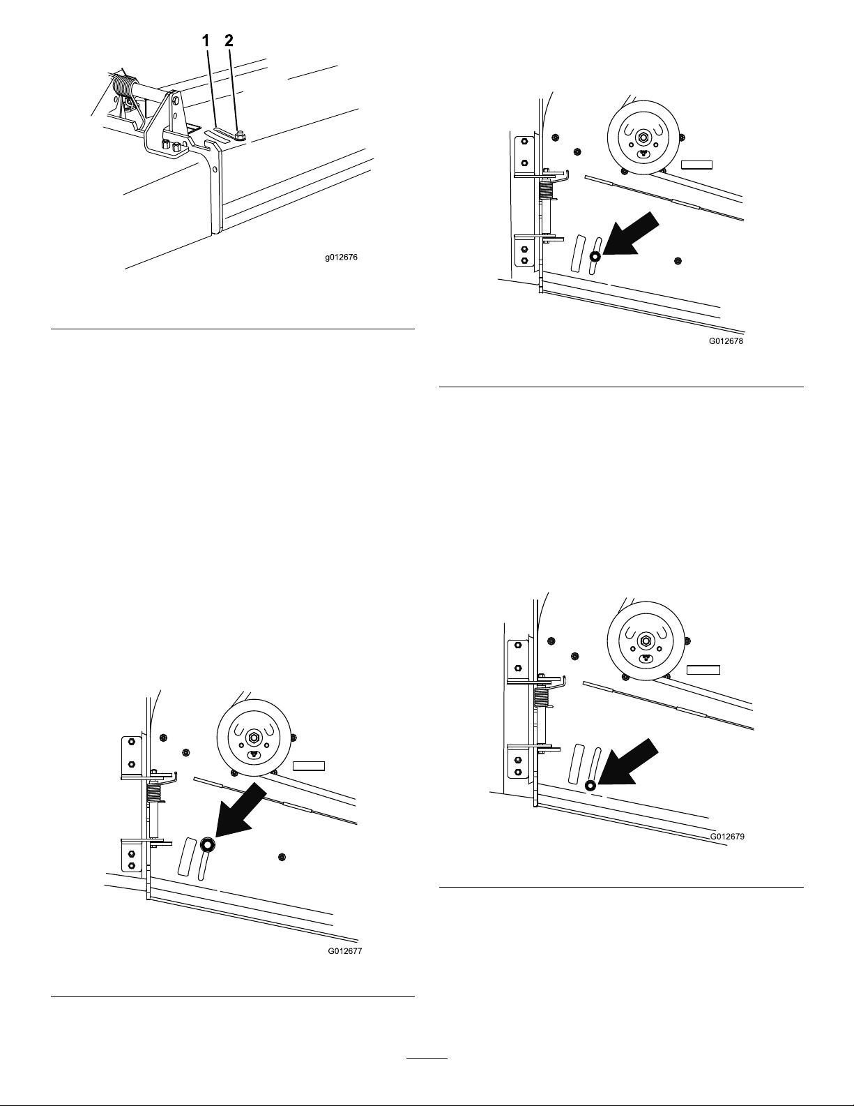
3.Toadjustthebafe,loosenthenut(Figure28).
4.Adjustthebafeandnutintheslottothedesired
dischargeowandtightenthenut.
24
Page 25
g012676
1 2
Figure28
G012677
G012678
G012679
PositionB
Usethispositionwhenbagging(Figure30).
1.Slot
2.Nut
PositioningtheFlowBafe
Thefollowingguresareonlyforrecommendeduse.
Adjustmentswillvarybygrasstype,moisturecontent,and
theheightofthegrass.
Note:Iftheenginepowerdrawsdown,andthemower
groundspeedisthesame,openupthebafe.
PositionA
Thisisthefull,rearposition(seeFigure29).Thesuggested
useforthispositionisasfollows:
•Inshort,lightgrassmowingconditions
•Indryconditions
•Smallergrassclippings
•Propelsgrassclippingsfartherawayfromthemower
Figure30
PositionC
Thisisthefull,openposition(Figure31).Thesuggesteduse
forthispositionisasfollows:
•Intall,densegrassmowingconditions
•Inwetconditions
•Lowerstheengine-powerconsumption
•Allowsincreasedgroundspeedinheavyconditions
Figure29
Figure31
25
Page 26

UsingtheMid-SizeWeight
•Weightsareinstalledtoimprovehandling,balance,and
improveperformance.W eightscanbeaddedorremoved
tocreateoptimizedperformanceunderdifferentmowing
conditionsandforoperatorpreference.
•Itisrecommendedthatweightsbeaddedorremovedone
atatimeuntilthedesiredhandingandbalanceisachieved.
Note:ContactanAuthorizedServiceDealertoordera
WeightKit.
WARNING
Excessiveweightchangescanaffectthehandling
andoperationofthemachine.Thiscouldcause
seriousinjurytoyouorbystanders.
Makeweightchangesinsmallincrementsonly.
Evaluatethemoweraftereachweightchangeto
ensurethemachinecanbeoperatedsafely.
26
Page 27

Maintenance
Note:Determinetheleftandrightsidesofthemachinefromthenormaloperatingposition.
RecommendedMaintenanceSchedule(s)
MaintenanceService
Interval
Aftertherst8hours
Aftertherst100hours
Beforeeachuseordaily
Every50hours
Every100hours
MaintenanceProcedure
•Checkthehydraulic-uidlevel.
•Changethehydrauliclter.
•Checkthewheel-lugnuts.
•Checkthewheel-hubnuts.
•Checkthesafety-interlocksystem.
•Checktheengine-oillevel.
•Cleantheair-intakescreen.
•Cleandebrisfromthehydraulic-oilcooler(ifequipped).
•Checkthebrakes.
•Inspecttheblades.
•Cleanthemowerdeck.
•Greasetheliftlinkage(moreoftenindirtyordustyconditions).
•Greasethemowerdeckspindles(moreoftenindirtyordustyconditions).
•Checkthesparkarrester(ifequipped).
•Checkthetirepressure.
•Checkthehydraulic-uidlevel.
•Changetheengineoil.(moreoftenindirtyordustyconditions)
•Checkthebattery.
•Checkandcleantheenginecoolingnsandshrouds.
•Servicethehydraulic-oilcoolerindirtyconditions(ifequipped).
•Checkthemower-deckbelt.
•Checkthepump-drivebelt.
•Checkthehydraulichoses.
Every150hours
Every200hours
Every250hours
Every300hours
Every500hours
Every600hours
Every800hours
Beforestorage
•Inspecttheprimarylterandair-inletscreen.
•Changetheengine-oillter.
•Check,cleanandgapthesparkplug.
•Checktheclutch.
•Cleantheengine-oilcooler.
•ChangethehydrauliclterandhydraulicoilwhenusingMobil®1oil.
•Replacetheprimaryairlter .(moreoftenindustyorsandyconditions)
•Checktheinner-airlter.
•Adjustthecaster-pivotbearing.
•Checkthewheel-hubnuts.
•ChangethehydrauliclterandhydraulicoilwhenusingT oro®HYPR-OIL™500
hydraulicoil.
•Replacetheinner-airlter.
•Greasethefrontwheelbearings(moreoftenindirtyordustyconditions).
•Greasethefrontcasterpivots(moreoftenindirtyordustyconditions).
•Replacethefuellter.
•Paintchippedsurfaces.
•Performallmaintenanceprocedureslistedabovebeforestorage.
Yearly
•Greasethefrontcasterpivots(moreoftenindirtyordustyconditions).
•Lubricatethecaster-wheelhubs.
Important:Refertoyourengineowner’smanualforadditionalmaintenanceprocedures.
27
Page 28
CAUTION
g018098
g017900
Ifyouleavethekeyintheignitionswitch,someonecouldaccidentlystarttheengineandseriouslyinjure
youorotherbystanders.
Removethekeyfromtheignitionanddisconnectthespark-plugwiresfromthesparkplugsbeforeyoudo
anymaintenance.Setthewiresasidesothattheydonotaccidentallycontactthesparkplugs.
Premaintenance
Procedures
RaisingtheMowerforAccess
Thefrontofthemowercanberaisedandsupportedonits
backforaccessunderthemachineformaintenance.
1.Raisetheplatform;refertoOperatingthePlatform
(page20).
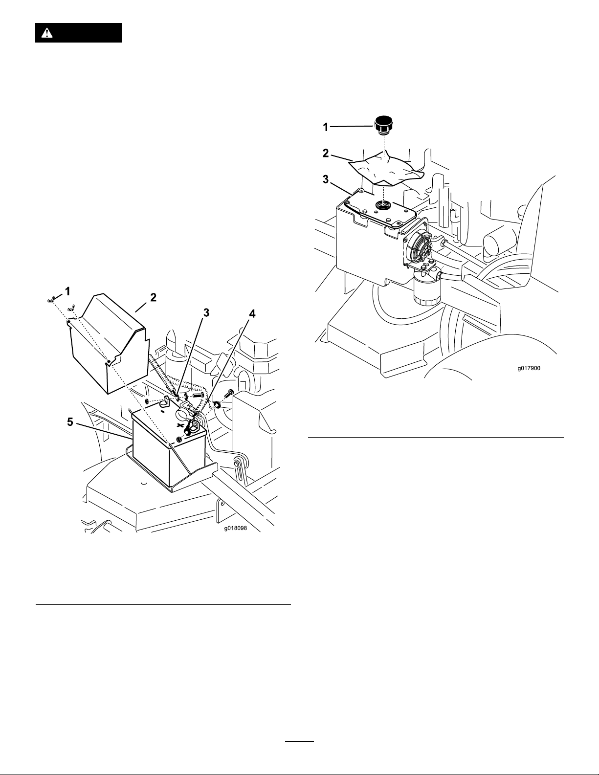
2.Removethebattery.
Figure32
1.Wingnut
2.Batterycover5.Battery
3.Negative-batterycable(–)
3.Drainthefuelfromthefueltank;refertoDraining
theFuelTank(page36).
4.Removethecapofthehydraulictank,andplaceapiece
ofplasticovertheopeningandinstallthehydrauliccap.
4.Positive-batterycable(+)
Figure33
1.Cap
2.Pieceofplastic
5.With2people,raisethefrontofthemowersothat
itrestsonthedrivetiresandtheplatformintheup
position.
6.Performanymaintenanceonthemachine.
7.With2people,lowerthefrontofthemowertothe
ground.
8.Removetheplasticunderthehydraulictankcap.
9.Installthebatteryforthemachine.
3.Hydraulictank
Note:Thiswillsealthehydraulictankandprevent
itfromleakingout.
28
Page 29
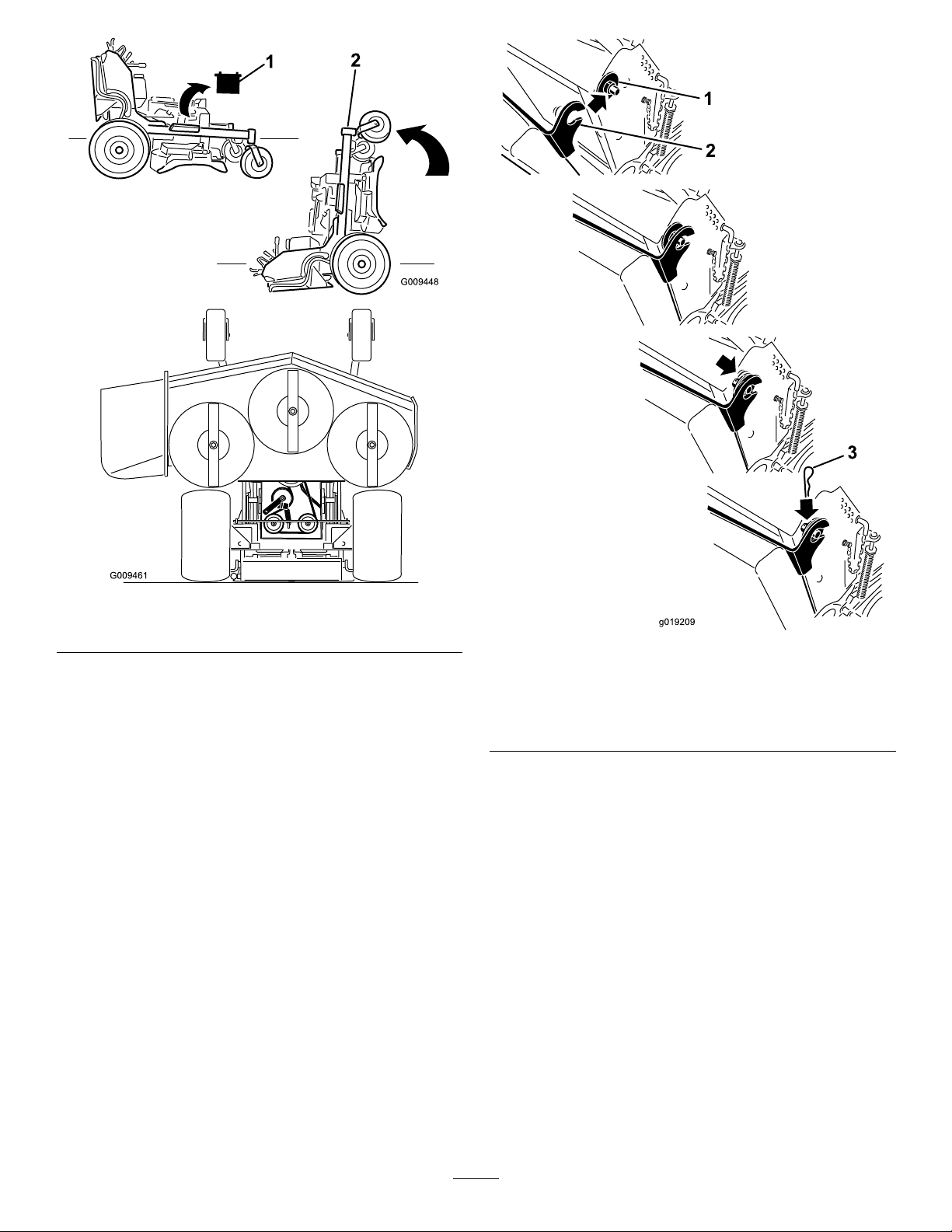
Figure34
g019209
1.Removebattery
2.Frontendofthemower
ReleasingtheCushionfor RearAccess
Youcanreleasethecushionforrearaccesstothemachinefor
maintenanceoradjustment.
1.Lowertheplatform.
2.Removethehairpin-cotterpinsoneachsideofthe
cushion.
3.Slidethelargewasherswiththeplasticbushingstothe
inside.
4.Removethecushion,andlowerittotheplatform.
5.Performanymaintenanceoradjustmentonthe
machine.
6.Raisethecushionandslideitontothepinsonboth
sidesofthemachine(Figure35).
7.Slidethelargewasherswiththeplasticbushings
intothecushionbracket,andsecurethemwitha
hairpin-cotterpin(Figure35).
1.Plasticbushingwiththe
largewasher
2.Cushionbracketwiththe
keyhole
Figure35
3.Hairpin-cotterpin
29
Page 30
Lubrication
G019356
g017738
g017739
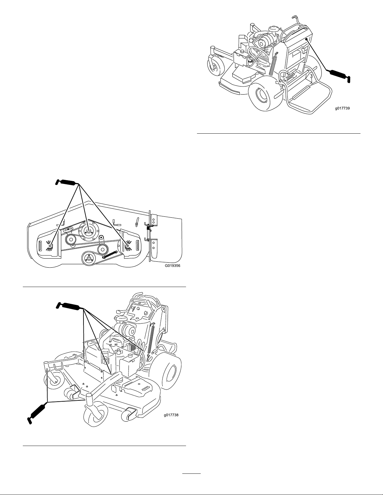
GreasewithNo.2generalpurposelithiumbaseor
molybdenumbasegrease.
LubricatingtheMachine
ServiceInterval:Every50hours—Greasetheliftlinkage
(moreoftenindirtyordustyconditions).
Every50hours—Greasethemowerdeckspindles
(moreoftenindirtyordustyconditions).
Every800hours/Yearly(whichevercomes
rst)—Greasethefrontwheelbearings(moreoftenin
dirtyordustyconditions).
Every800hours/Yearly(whichevercomes
rst)—Greasethefrontcasterpivots(moreoftenin
dirtyordustyconditions).
Usethefollowinggraphicsforlocatingthegreasepoints.
Figure36
Figure38
GreasingtheFrontCaster Pivots
ServiceInterval:Yearly
Lubricatethefrontcasterpivotsonceayear.
1.Removethedustcapandadjustthecasterpivots;refer
toAdjustingtheCaster-PivotBearing(page42).
Note:Keepthedustcapoffuntilgreasingisdone.
2.Removethehexplug.
3.Threadagreasettingintothehole.
4.Pumpgreaseintothettinguntilitoozesoutaround
thetopbearing.
5.Removethegreasettinginthehole.Installthehex
plugandcap.
Figure37
30
Page 31

LubricateCaster-WheelHubs
ServiceInterval:Yearly
1.Stoptheengine,waitforallmovingpartstostop,
engagetheparkingbrake,andremovethekey .
Figure39
13.Torquethenutto8to9N-m(71to80in-lb),loosen,
thentorqueitto2to3N-m(20to25in-lb).
Note:Makesureaxledoesnotextendbeyondeither
nut.
14.Installthesealguardsoverthewheelhubandinsert
wheelintocasterfork.
15.Installcasterboltandtightennutfully.
Important:T opreventsealandbearingdamage,check
thebearingadjustmentoftenbyspinningthecaster
tire.Thetireshouldnotspinfreely(morethan1or2
revolutions)orhaveanysideplay.Ifthewheelspins
freely,adjustthetorqueonthespacernutuntilthere
isaslightamountofdrag,andapplythread-locking
adhesive.
1.Sealguard2.Spacernutwithwrench
2.Removethecasterwheelfromthecasterforks.
3.Removethesealguardsfromthewheelhub.
4.Removeoneofthespacernutsfromtheaxleassembly
inthecasterwheel.
Note:Thread-lockingadhesivehasbeenappliedto
lockthespacernutstotheaxle.Removetheaxle(with
theotherspacernutstillassembledtoit)fromthe
wheelassembly.
5.Pryoutthesealsandinspectbearingsforwearor
damage,andreplaceifnecessary.
6.Packthebearingswithageneral-purposegrease.
7.Insert1bearingand1sealintothewheel.
Note:Thesealsmustbereplaced.
8.Iftheaxleassemblyhashadbothspacernutsremoved
(orbrokenloose),applyathread-lockingadhesiveto
onespacernutandthreaditontotheaxlewiththe
wrenchatsfacingoutward.
ats
Note:DoNotthreadspacernutallofthewayonto
theendoftheaxle.Leaveapproximately3mm(1/8
inch)fromtheoutersurfaceofthespacernuttothe
endoftheaxleinsidethenut.
9.Inserttheassemblednutandaxleintothewheelonthe
sideofthewheelwiththenewsealandbearing.
10.Withtheopenendofthewheelfacingup,llthearea
insidethewheelaroundtheaxlefullofgeneral-purpose
grease.
11.Insertthesecondbearingandthenewsealintothe
wheel.
12.Applyathread-lockingadhesivetothesecondspacer
nut,andthreaditontotheaxlewiththewrenchats
facingoutward.
31
Page 32
EngineMaintenance
ServicingtheAirCleaner
ServiceInterval:Every150hours
Every300hours/Yearly(whichevercomes
rst)—Replacetheprimaryairlter.(moreoftenin
dustyorsandyconditions)
Every300hours—Checktheinner-airlter.
Every600hours—Replacetheinner-airlter.
7.Inspecttheprimarylterfordamagebylookinginto
thelterwhileshiningabrightlightontheoutsideof
thelter.
Note:Holesinthelterwillappearasbrightspots.
Note:Ifthelterisdamaged,discardit.
ServicingthePrimaryFilter
•Iftheprimarylterisdirty,bent,ordamaged,replaceit.
•Donotcleantheprimarylter.
Note:Checktheltersmorefrequentlyiftheoperating
conditionsareextremelydustyorsandy.
RemovingtheFilters
1.DisengagethePTO ,movethemotion-controlleversto
theneutral-lockedposition,andsettheparkingbrake.
2.Stoptheengine,removethekey,andwaitforallmoving
partstostopbeforeleavingtheoperatingposition.
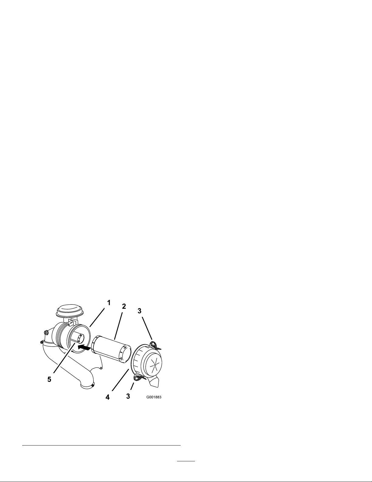
3.Releasethelatchesontheaircleanerandpullthe
air-cleanercoverofftheair-cleanerbody(Figure40).
4.Cleantheinsideoftheair-cleanercoverwith
compressedair.
5.Gentlyslidetheprimarylteroutoftheair-cleaner
body(Figure40).
Note:Avoidknockingthelterintothesideofthe
body.
6.Removetheinnerlteronlyifyouintendtoreplaceit.
Important:Neverattempttocleantheinnerlter.
Ifthesafetylterisdirty,thentheprimarylteris
damaged.Replacebothlters.
ServicingtheSafetyFilter
Replacethesafetylter,nevercleanit.
Important:Neverattempttocleanthesafetylter.
Ifthesafetylterisdirty,thentheprimarylteris
damaged.Replacebothlters.
InstallingtheFilters
Important:Topreventenginedamage,alwaysoperate
theenginewithbothairltersandcoverinstalled.
1.Ifinstallingnewlters,checkeachlterforshipping
damage.
Note:Donotuseadamagedlter.
2.Ifthesafetylterisbeingreplaced,carefullyslideit
intothelterbody(Figure40).
3.Carefullyslidetheprimarylteroverthesafetylter
(Figure40).
Note:Ensurethattheprimarylterisfullyseatedby
pushingonitsouterrimwhileinstallingit.
Important:Donotpressonthesoft,insidearea
ofthelter.
Figure40
1.Air-cleanerbody4.Air-cleanercover
2.Primarylter5.Innerlter
3.Latch
4.Installtheair-cleanercoverandsecurethelatches
(Figure40).
32
Page 33
ServicingtheEngineOil
g017552
0
0
50
SAE 30
G008792
1
2
5
6
7
3
9
10
4
8
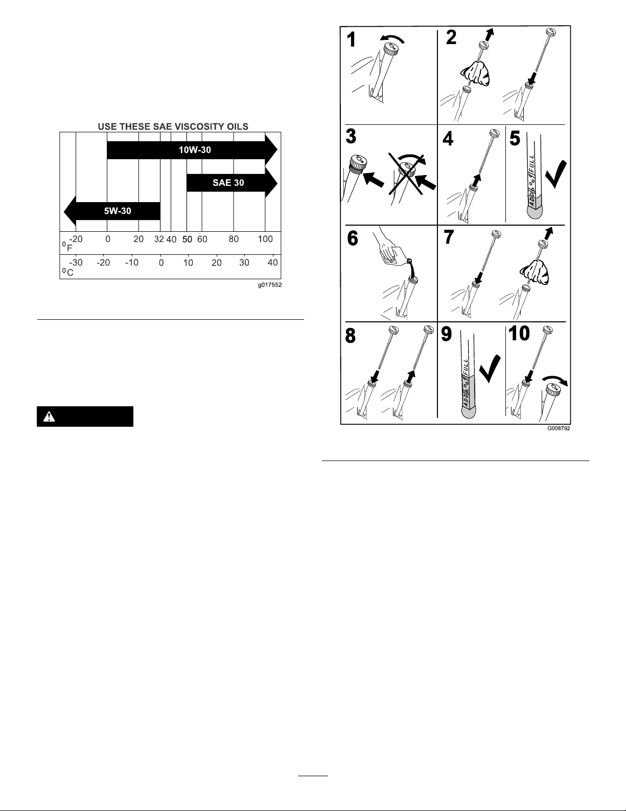
OilType:Detergentoil(APIserviceclassSJorhigher)
OilCapacity:withalterchange,1.9L(61oz);withno
lterchange,1.6L(54oz)
Viscosity:Seethetablebelow.
Figure41
CheckingtheEngine-OilLevel
ServiceInterval:Beforeeachuseordaily
Note:Checktheoilwhentheengineiscold.
WARNING
Contactwithhotsurfacesmaycausepersonal
injury.
Keephands,feet,face,clothingandotherbody
partsawayfromthemuferandotherhotsurfaces.
Important:Donotoverllthecrankcasewithoil,
becausedamagetotheenginemayresult.Donotrun
enginewithoilbelowtheLowmark,becausetheengine
maybedamaged.
1.DisengagethePTO ,movethemotion-controlleversto
theneutral-lockedposition,andsettheparkingbrake.
2.Stoptheengine,removethekey,andwaitforall
movingpartstostopbeforeleavingtheoperating
position(Figure42).
Figure42
33
Page 34
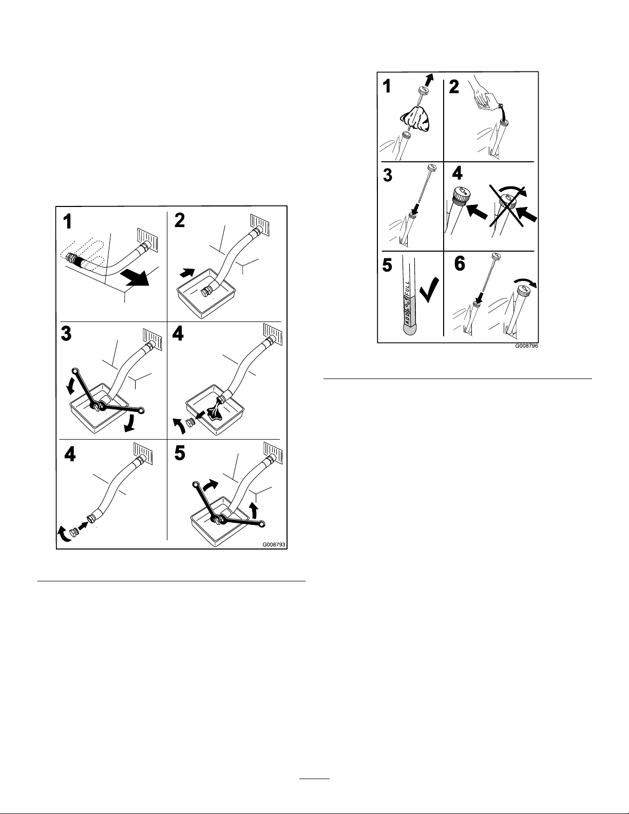
ChangingtheEngineOil
G008793
1
2
3
4
4
5
G008796
2
3
4
5
6
1
ServiceInterval:Every100hours(moreoftenindirtyor
dustyconditions)
Note:Disposeoftheusedoilatarecyclingcenter.
1.Parkthemachinesothattherearisslightlylowerthan
thefronttoensuretheoildrainscompletely.
2.DisengagethePTO ,movethemotion-controlleversto
theneutral-lockedpositionandsettheparkingbrake.
3.Stoptheengine,removethekey,andwaitforall
movingpartstostopbeforeleavingtheoperating
position(Figure43).
4.Slowlypourapproximately80%ofthespeciedoil
intothellertubeandslowlyaddtheadditionaloilto
bringittotheFullmark(Figure44).
Figure44
5.Starttheengineanddrivetoaatarea.
6.Checktheoillevelagain.
Figure43
34
Page 35
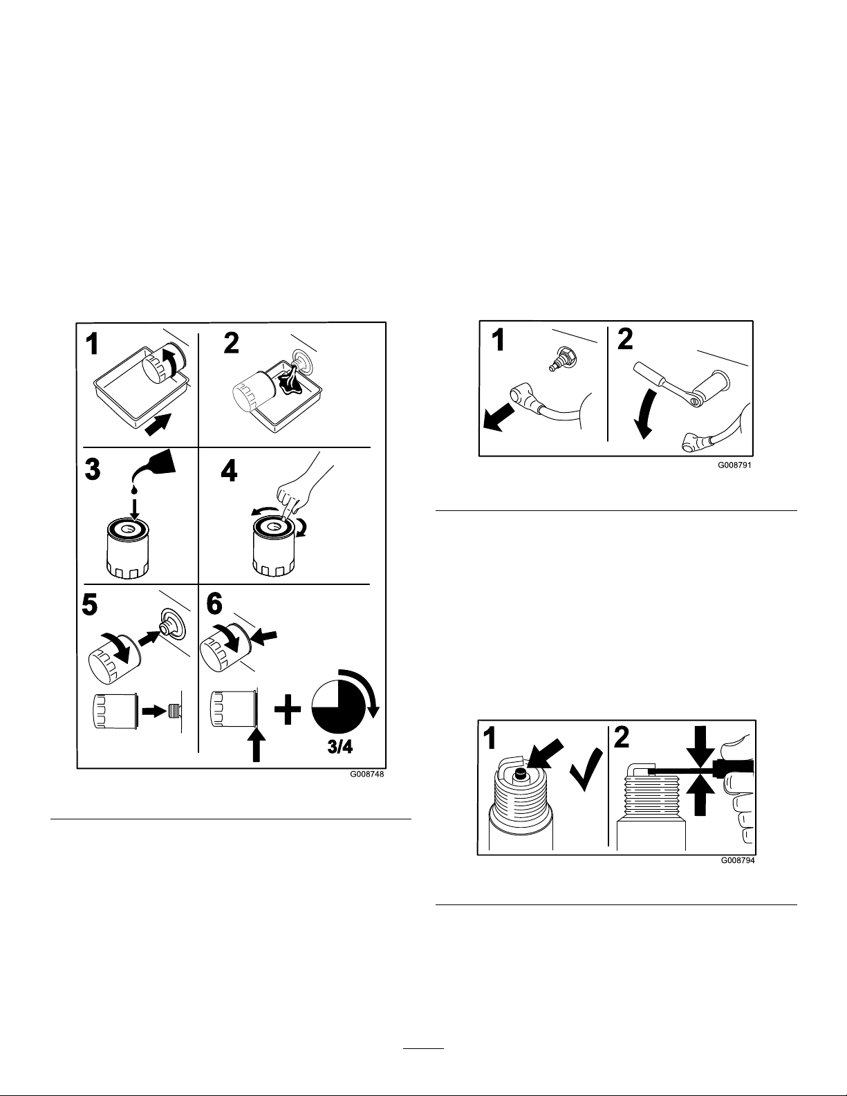
ChangingtheEngine-OilFilter
G008748
3/4
1
2
3
4
5
6
G008794
1
2
ServiceInterval:Every200hours
Note:Changetheengine-oilltermorefrequentlywhen
operatingconditionsareextremelydustyorsandy.
1.Draintheoilfromtheengine;refertoChangingthe
EngineOil(page34).
2.Placearagundertheoilltertosoakupanyspilledoil.
Important:Spilledoilmaydrainundertheengine
andontotheclutch.Oilspilledontheclutchmay
damagetheclutch,causethebladestostopslowly
whentheclutchisintheOffposition,andcause
theclutchtoslipwhentheclutchisswitchedto
theOnposition.Wipeupanyspilledoil.
3.Changetheengine-oillter(Figure45).
Useasparkplugwrenchforremovingandinstallingthespark
plug(s)andagappingtool/feelergaugetocheckandadjust
theairgap.Installanewsparkplug(s)ifnecessary.
TypeforallEngines:Kohler2513214-cChampion
XC12YCorequivalent
AirGap:0.75mm(0.03inch)
RemovingtheSparkPlug
1.DisengagethePTO ,movethemotion-controlleversto
theneutral-lockedposition,andsettheparkingbrake.
2.Stoptheengine,removethekey,andwaitforallmoving
partstostopbeforeleavingtheoperatingposition.
3.RemovethesparkplugasshowninFigure46.
Note:Ensurethattheoil-ltergaskettouchesthe
engine,andthenanextra3/4turniscompleted.
4.Fillthecrankcasewiththepropertypeofnewoil;refer
toChangingtheEngineOil(page34).
Figure45
Figure46
CheckingtheSparkPlug
Important:Donotcleanthesparkplug(s).Always
replacethesparkplug(s)whenithasablackcoating,
wornelectrodes,anoilylm,orcracks.
Ifyouseelightbrownorgrayontheinsulator,theengineis
operatingproperly .Ablackcoatingontheinsulatorusually
meanstheaircleanerisdirty.
Setthegapto0.75mm(0.03inch).
Figure47
ServicingtheSparkPlug
ServiceInterval:Every200hours
Makesuretheairgapbetweenthecenterandsideelectrodes
iscorrectbeforeinstallingthesparkplug.
35
Page 36
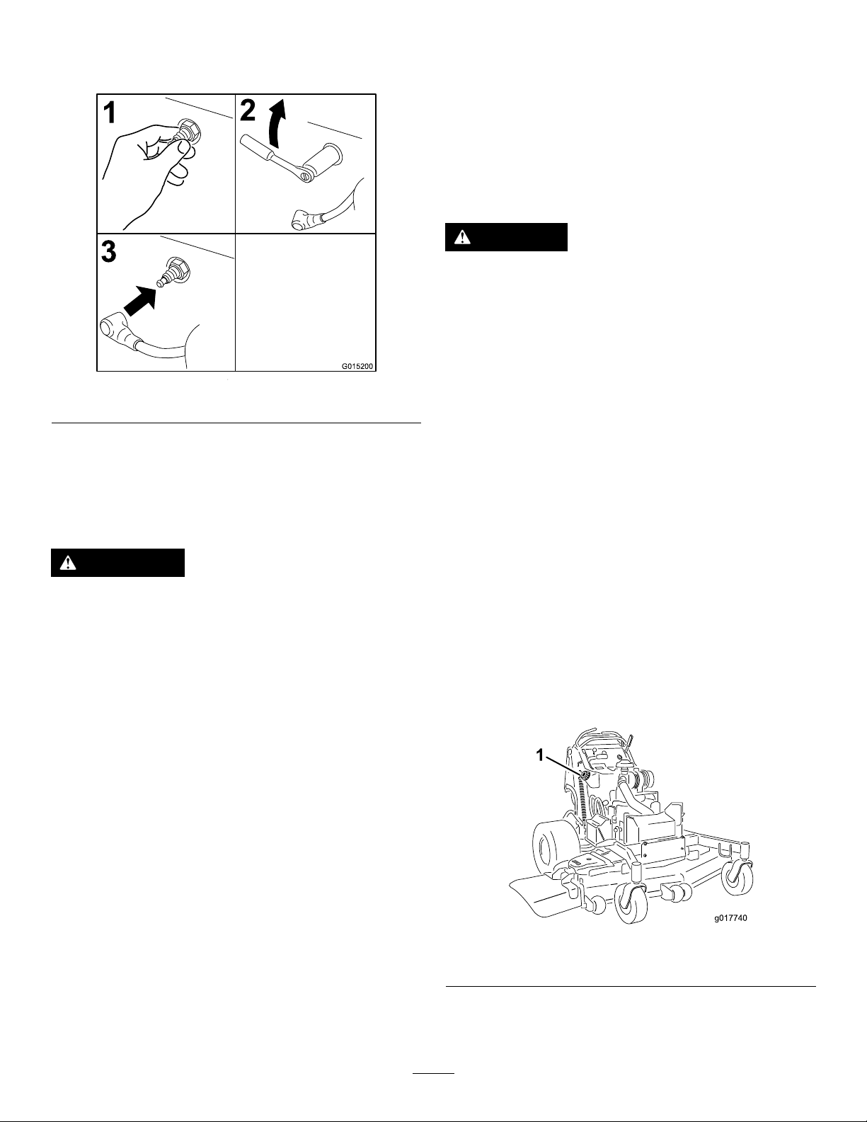
InstallingtheSparkPlug
3
2
1
G015200
1
g017740
Tightenthesparkplug(s)to22N-m(16ft-lb).
Figure48
CheckingtheSparkArrester (ifequipped)
ServiceInterval:Every50hours
WARNING
Hotexhaust-systemcomponentsmayignite
gasolinevaporsevenaftertheengineisstopped.
Hotparticlesexhaustedduringengineoperation
mayigniteammablematerials.Firemayresultin
personalinjuryorpropertydamage.
Donotrefuelorruntheengineunlessthespark
arresterisinstalled.
FuelSystem
Maintenance
DrainingtheFuelTank
Note:Thereisnootherrecommendedwaytodrainfuel
fromthetank,otherthanusingasyphonpump.Asyphon
pumpcanbepurchasedatahardwarestore.
DANGER
Incertainconditions,gasolineisextremely
ammableandhighlyexplosive.Areorexplosion
fromgasolinecanburnyouandothersandcan
damageproperty.
•Draingasolinefromthefueltankwhenthe
engineiscold.Dothisoutdoorsinanopenarea.
Wipeupanygasolinethatspills.
•Neversmokewhendraininggasoline,andstay
awayfromanopename,orwhereasparkmay
ignitethegasolinefumes.
1.DisengagethePTO ,movethemotion-controlleversto
theneutral-lockedposition,andsettheparkingbrake.
2.Stoptheengine,removethekey,andwaitforallmoving
partstostopbeforeleavingtheoperatingposition
3.Cleanaroundthefuelcaptopreventdebrisfrom
gettingintothefueltank(Figure50).
4.Removethefuelcap.
5.Insertasyphonpumpintothefueltank.
6.Usingthesyphonpump,drainthefuelintoacleangas
can(Figure49).
7.Wipeupanyspilledfuel.
1.Stoptheengine,waitforallmovingpartstostop,
engagetheparkingbrake,andremovethekey .
2.Waitforthemufertocool.
3.Ifanybreaksinthescreenorweldsareobserved,
replacethearrester.
4.Ifpluggingofthescreenisobserved,removethe
arrester,shakelooseparticlesoutofthearrester,and
cleanthescreenwithawirebrush(soakinsolventif
necessary).
5.Installarresteronexhaustoutlet.
Figure49
1.Fuelcap
36
Page 37
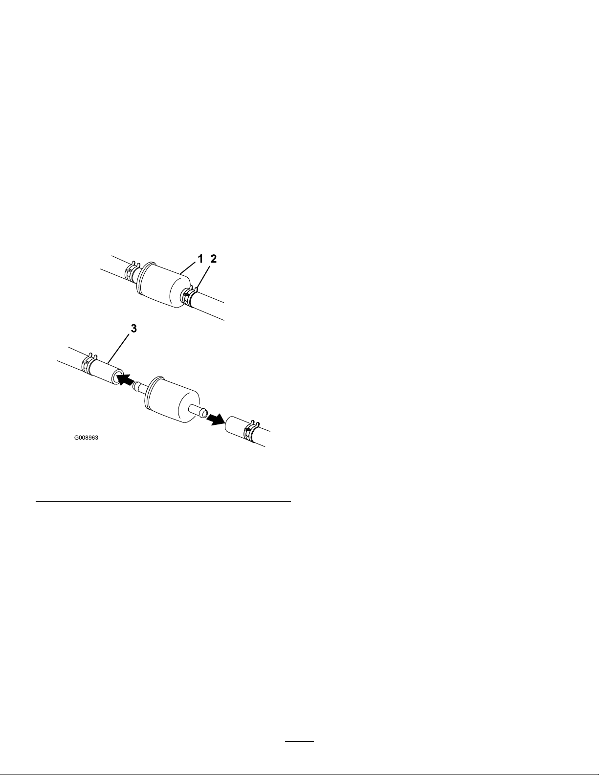
ServicingtheFuelFilter
G008963
12
3
ReplacingtheFuelFilter
ServiceInterval:Every800hours/Yearly(whichevercomes
rst)
Donotinstalladirtylterifitisremovedfromthefuelline.
ServicingtheElectronic Fuel-InjectionSystem
Thismachinecontainsanelectronicfuel-injectionsystem.It
controlsthefuelowunderdifferentoperatingconditions.
Theelectronic-controlunit(ECU)continuouslymonitorsthe
operationoftheEFIsystem.
Note:Wipeupanyspilledfuel.
1.DisengagethePTOandsettheparkingbrake.
2.Stoptheengine,removethekey,andwaitforallmoving
partstostopbeforeleavingtheoperatingposition.
3.Closethefuelshut-offvalve(behindtheoperator
cushion).
4.Squeezetheendsofthehoseclampstogetherandslide
themawayfromthelter(Figure50).
Ifaproblemorfaultwithinthesystemisdetected,the
malfunction-indicatorlight(MIL)isilluminated.TheMILis
theredlightlocatedintheconsolepanel.
OncetheMILilluminates,initialtroubleshootingchecks
shouldbemade.
Ifthesechecksdonotcorrecttheproblem,furtherdiagnosis
andservicingbyanAuthorizedServiceDealerisnecessary.
Figure50
1.Filter3.Fuelline
2.Hoseclamp
5.Removethelterfromthefuellines.
6.Installanewlterandmovethehoseclampscloseto
thelter.
7.Openthefuelshut-offvalve.
8.Checkforfuelleaksandrepairifneeded.
9.Wipeupanyspilledfuel.
37
Page 38
ElectricalSystem
g018098
Maintenance
ServicingtheBattery
ServiceInterval:Every100hours
Alwayskeepthebatterycleanandfullycharged.Useapaper
toweltocleanthebatterycase.Ifthebatteryterminalsare
corroded,cleanthemwithasolutionoffourpartswaterand
onepartbakingsoda.Applyalightcoatingofgreasetothe
batteryterminalstopreventcorrosion.
Voltage:12V
WARNING
CALIFORNIA
Proposition65Warning
Batteryposts,terminals,andrelated
accessoriescontainleadandleadcompounds,
chemicalsknowntotheStateofCalifornia
tocausecancerandreproductiveharm.
Washhandsafterhandling.
WARNING
Incorrectbattery-cableroutingcoulddamagethe
machineandcablescausingsparks.Sparkscan
causethebatterygassestoexplode,resultingin
personalinjury.
•Alwaysdisconnectthenegative(black)battery
cablebeforedisconnectingthepositive(red)
cable.
•Alwaysconnectthepositive(red)batterycable
beforeconnectingthenegative(black)cable.
1.DisengagethePTOandsettheparkingbrake.
2.Stoptheengine,removethekey,andwaitforallmoving
partstostopbeforeleavingtheoperatingposition.
3.Lifttheblack,rubbercoveronthenegativecable.
4.Disconnectthenegativebatterycablefromthenegative
(-)batteryterminal(Figure51).
DANGER
Donotdrinkelectrolyte,andavoidcontactwith
skin,eyesorclothing.Wearsafetyglassestoshield
youreyesandrubberglovestoprotectyourhands.
Batteryelectrolytecontainssulfuricacidwhichisa
deadlypoisonandcausessevereburns.
RemovingtheBattery
WARNING
Batteryterminalsormetaltoolscouldshortagainst
metalmachinecomponentscausingsparks.Sparks
cancausethebatterygassestoexplode,resulting
inpersonalinjury.
•Whenremovingorinstallingthebattery,donot
allowthebatteryterminalstotouchanymetal
partsofthemachine.
•Donotallowmetaltoolstoshortbetween
thebatteryterminalsandmetalpartsofthe
machine.
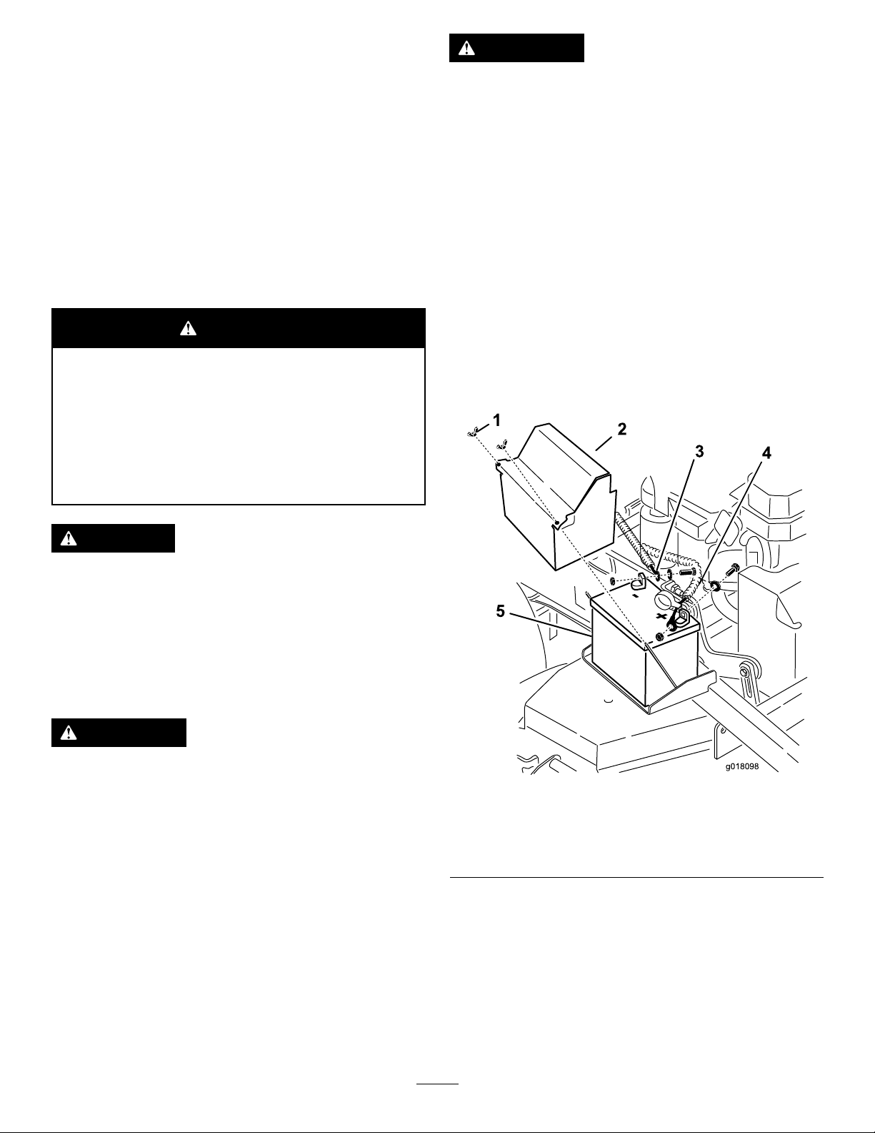
Figure51
1.Wingnut4.Positivebatterycable
2.Batterycover5.Battery
3.Negativebatterycable
5.Slidetheredterminalbootoffthepositive(red)battery
terminal.
6.Removethepositive(red)batterycable(Figure51).
7.Removethebatteryholddownplate(Figure51),and
removethebattery.
38
Page 39
InstallingtheBattery
g017915
1
1.Placethebatteryontothemachine(Figure51).
2.Securethebatterywiththeholddownplate,j-bolts,
andlocknuts.
3.Installthepositive(red)batterycabletopositive(+)
batteryterminalwithanut,awasher,andabolt(Figure
51).
4.Slidetherubbercoveroverthepost.
5.Installthenegativebatterycableandthegroundwire
tothenegative(-)batteryterminalwithanut,awasher,
andabolt(Figure51).
6.Slidetherubbercoveroverthepost.
ChargingtheBattery
WARNING
Chargingthebatteryproducesgassesthatcan
explode.
Neversmokenearthebatteryandkeepsparksand
amesawayfrombattery.
Important:Alwayskeepthebatteryfullycharged
(1.265specicgravity)topreventbatterydamagewhen
thetemperatureisbelow32°F(0°C).
1.Removethebatteryfromthechassis;refertoRemoving
theBattery(page38).
2.Checktheelectrolytelevel.
3.Ensurethatthellercapsareinstalledonthebattery.
Figure52
1.PositiveBatteryPost
2.NegativeBatteryPost
3.Red(+)ChargerLead
4.Black(-)ChargerLead
ServicingtheFuses
Theelectricalsystemisprotectedbyfuses,andrequiresno
maintenance.Ifafuseblows,checkthecomponentorcircuit
foramalfunctionorshort.
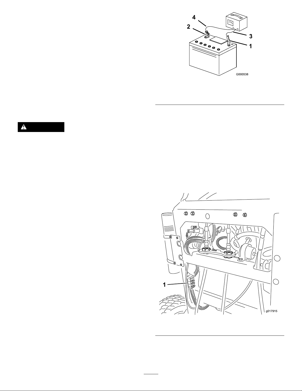
1.Releasethecushionfromtherearofthemachine.
2.Pulloutonthefusetoremoveorreplaceit(Figure53).
3.Installthecushiontotherearofthemachine.
Note:Ensurethatthecorrect-sizefuseisinstalled
Figure53.
4.Chargethebatteryfor1hourat25to30ampsor6
hoursat4to6amps.
5.Whenthebatteryisfullycharged,unplugthecharger
fromtheelectricaloutlet,anddisconnectthecharger
leadsfromthebatteryposts(Figure52).
6.Installthebatteryontothemachineandconnectthe
batterycables;refertoInstallingtheBattery(page39).
Note:Donotrunthemachinewiththebattery
disconnected;electricaldamagemayoccur.
Figure53
1.Fuses
39
Page 40
JumpStartingtheMachine
g017914
1
1.Checkandcleancorrosionfromthebatteryterminals
beforejumpstartingthemachine.Ensurethatthe
connectionsaretight.
CAUTION
Corrosionorlooseconnectionscancause
unwantedelectricalvoltagespikesatanytime
duringthejumpstartingprocedure.
Donotattempttojumpstartwithlooseor
corrodedbatteryterminalsordamagetothe
engineorEFImayoccur.
sameratedsystemvoltage.Theseinstructionsarefor
negativegroundsystemsonly.
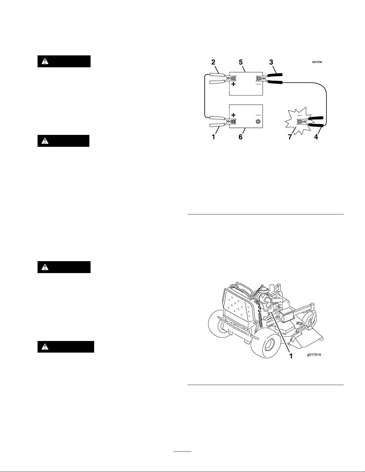
4.Connectthepositive(+)cabletothepositive(+)
terminalofthedischargedbatterythatiswiredtothe
starterorsolenoidasshowninFigure54.
DANGER
Jumpstartingaweakbatterythatiscracked,
frozen,haslowelectrolytelevel,oran
open/shortedbatterycell,cancausean
explosionresultinginseriouspersonalinjury.
Donotjumpstartaweakbatteryifthese
conditionsexist.
2.Makesurethattheboosterbatteryisagoodandfully
chargedlead-acidbatteryat12.6voltsorgreater.Use
propersizedjumpercableswithshortlengthstoreduce
voltagedropbetweensystems.
3.Makesurethatthecablesarecolorcodedorlabeledfor
thecorrectpolarity .
CAUTION
Connectingthejumpercablesincorrectly
(wrongpolarity)canimmediatelydamagethe
EFIsystem.
Becertainofbatteryterminalpolarityand
jumpercablepolaritywhenhookingup
batteries.
Figure54
1.Positive(+)cableon
dischargedbattery
2.Positive(+)cableon
boosterbattery
3.Negative(–)cableonthe
boosterbattery
4.Negative(–)cableonthe
engineblock
5.Connecttheotherendofthepositivecabletothe
positiveterminaloftheboosterbattery.
6.Connecttheblacknegative(–)cabletotheother
terminal(negative)oftheboosterbattery.
7.Makethenalconnectionontheengineblockof
thestalledvehicle(nottothenegativebatterypost)
awayfromthebatteryandstandback(Figure55).
5.Boosterbattery
6.Dischargedbattery
7.Engineblock
WARNING
Batteriescontainacidandproduceexplosive
gases.
•Shieldyoueyesandfacefromthebatteries
atalltimes.
•Donotleanoverthebatteries.
Note:Besurethattheventcapsaretightandlevel.
Placeadampcloth,ifavailable,overanyventcapson
bothbatteries.Besurethatthevehiclesdonottouch
andthatbothoftheelectricalsystemsareoffandatthe
Figure55
1.Engineblock
8.Startthevehicle,andremovethecablesinthe
reverseorderofconnection(theengineblock(black)
connectionisthersttodisconnect.
40
Page 41
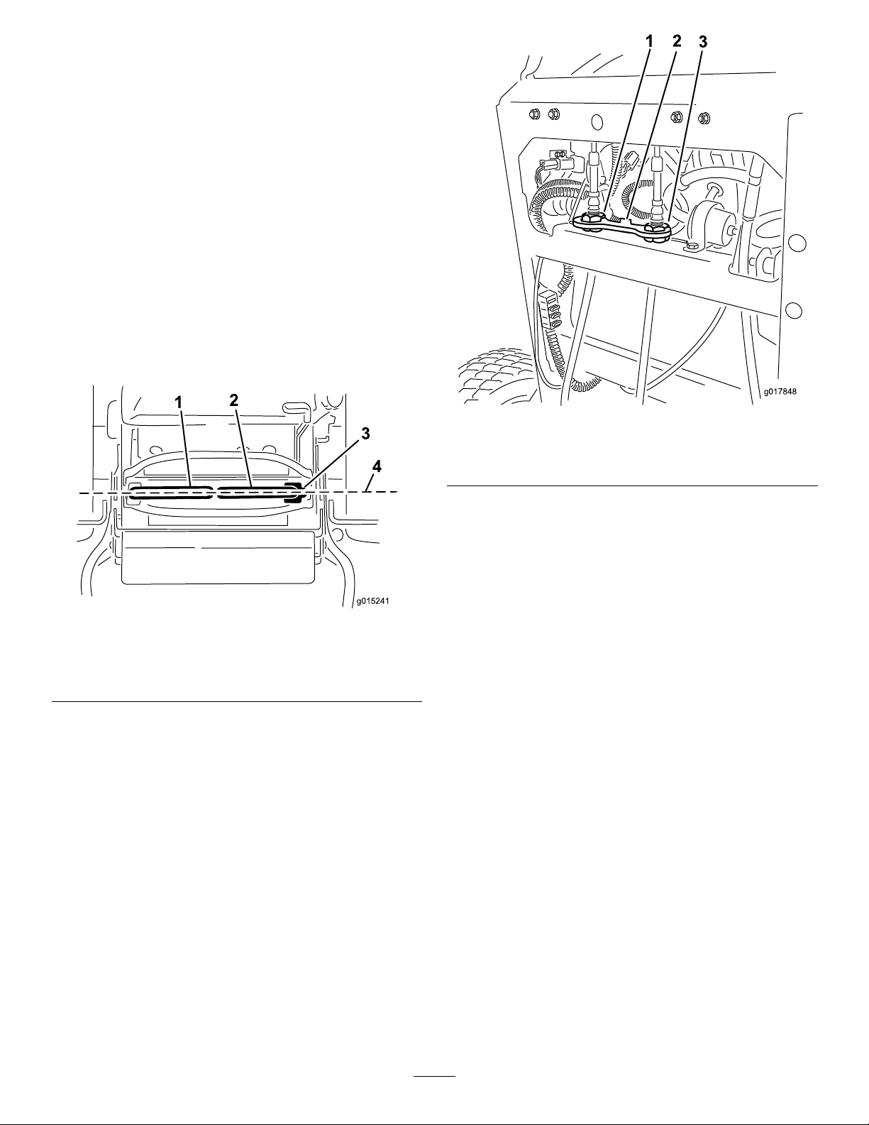
DriveSystem
g015241
3
g017848
Maintenance
AdjustingtheTracking
Note:Determinetheleftandrightsidesofthemachine
fromthenormaloperatingposition.
1.Pushbothcontrolleversforwardthesamedistance.
2.Checkifthemachinepullstooneside.
Note:Ifitdoes,stopthemachineandsettheparking
brake.
3.Releasethecushionfromtherearofthemachine.
4.Rotatetherightcableadjustmenttopositiontheright
motioncontrolinthecenterofthecontrolpanel
neutral-lockslot(Figure57).
Figure57
Figure56
1.Leftmotion-controllever
2.Rightmotion-controllever4.Alignthecontrollevers
5.Rotatetheleftcableadjustmenttomatchtheleft
wheelspeedtothepreviouslysetrightwheelspeed.
6.Adjustinquarter-turnincrementsuntilthemachine
tracksstraight.
Note:Onlyadjusttheleftcabletomatchtheleft
wheelspeedtotherightwheelspeed.Donotadjust
therightwheelspeedasthiswillpositiontheright
motion-controlleveroutofthecenterforthecontrol
panelneutral-lockslot.
3.Neutral-lockedposition
fronttoback
1.Leftcableadjustment
2.Cablelock
7.Checkforpropertracking.
Note:Ifthemachinewillnotstartafteradjusting
thetracking,makesureproximityswitchtargetaligns
withboltattachedtomotion-controllever;referto
AdjustingtheProximitySwitch(page41).
8.Repeatthecableadjustmentuntilthetrackingis
correct.
9.Checkthatthemachinedoesnotcreepfromneutral
withtheparkbrakesdisengaged.
Important:Donotrotatethelinkagetoofar,asthis
maycausethemachinetocreepinneutral.
3.Rightcableadjustment
AdjustingtheProximitySwitch
Usethisprocedureifthemachinewillnotstartafteradjusting
thetracking.
1.Ensurethattheboltattachedtothemotion-control
leveralignswiththeproximityswitchtarget(Figure58).
2.Ifneeded,loosentheboltsandadjusttheproximity
switchuntilthetargetalignswiththeboltattachedto
themotion-controllever(Figure58).
3.Checkthedistanceofthebolttotheproximityswitch;
itneedstobebetween0.51to1.02mm(0.02to0.04
inches)asshowninFigure58.
4.Ifadjustmentisneeded,loosenthejamnutandadjust
thebolttothecorrectdistance.
5.Tightenthejamnutafteradjustingthebolt(Figure58).
6.Testthesafety-interlocksystembeforeoperation.
41
Page 42
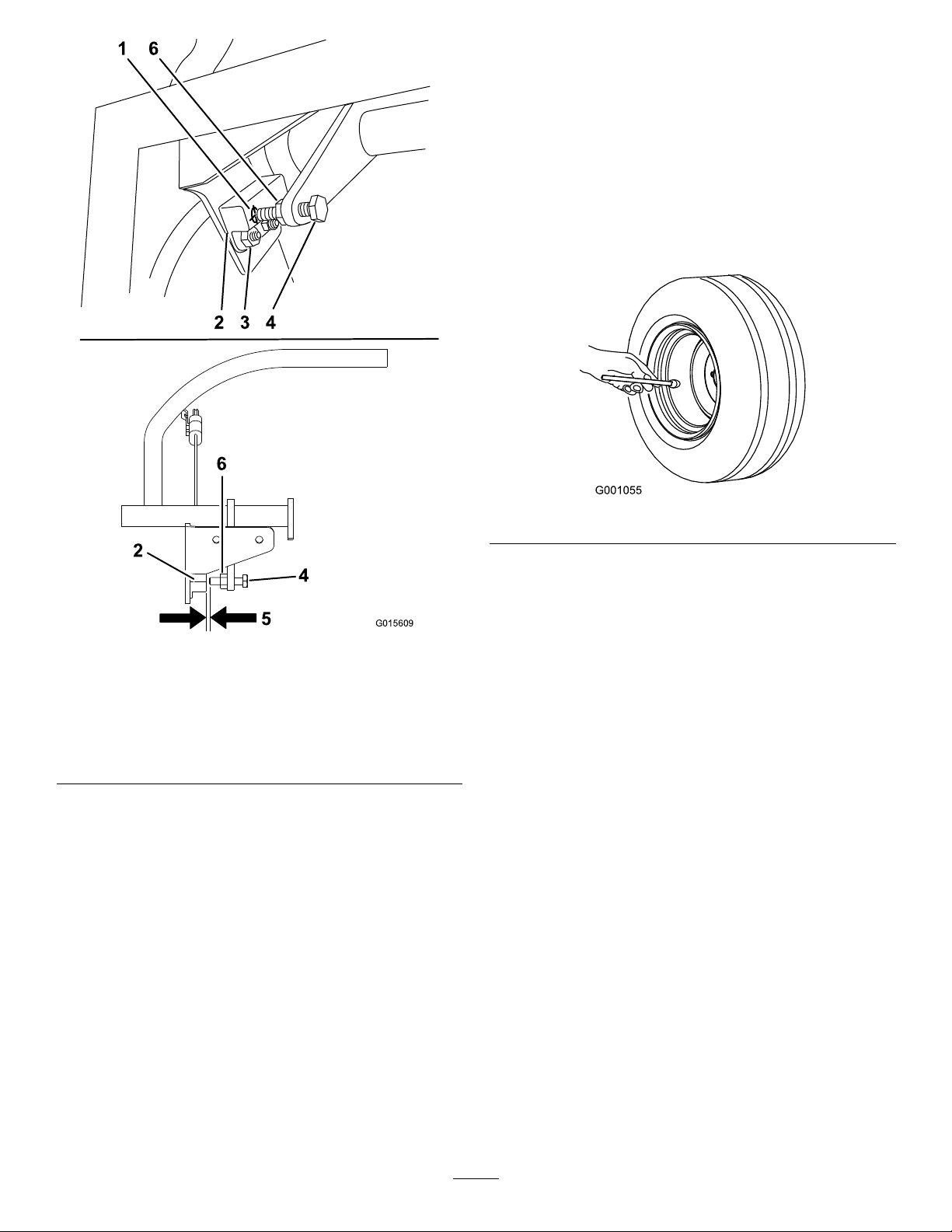
G015609
1 6
2 3 4
4
2
5
6
CheckingtheTirePressure
ServiceInterval:Every50hours/Monthly(whichever
comesrst)
Maintaintheairpressureinthereartiresat83to97kPa(12
to14psi).
Important:Uneventirepressurecancauseanuneven
cut.
Note:Thefronttiresaresemi-pneumatictiresanddonot
requireair-pressuremaintenance.
1.Proximityswitchtarget4.Boltattachedtothe
2.Proximityswitch5.Distancebetween0.51
3.Boltsandnuts6.Jamnut
Figure58
motion-controllever
to1.02mm(0.02to0.04
inches)isneeded
Figure59
AdjustingtheCaster-Pivot Bearing
ServiceInterval:Every500hours/Yearly(whichevercomes
rst)
1.Disengagetheblade-controlswitch(PTO),movethe
motioncontrolleverstotheneutral-lockedposition,
andsettheparkingbrake.
2.Stoptheengine,removethekey,andwaitforallmoving
partstostopbeforeleavingtheoperatingposition.
3.Removethedustcapfromthecasterandtightenthe
locknut(Figure60).
4.Tightenthelocknutuntilthespringwashersareat,
andthenbackoffa1/4turntoproperlysetthepreload
onthebearings(Figure60).
Important:Makesurethatthespringwashersare
installedcorrectlyasshowninFigure60.
5.Installthedustcap(Figure60).
42
Page 43
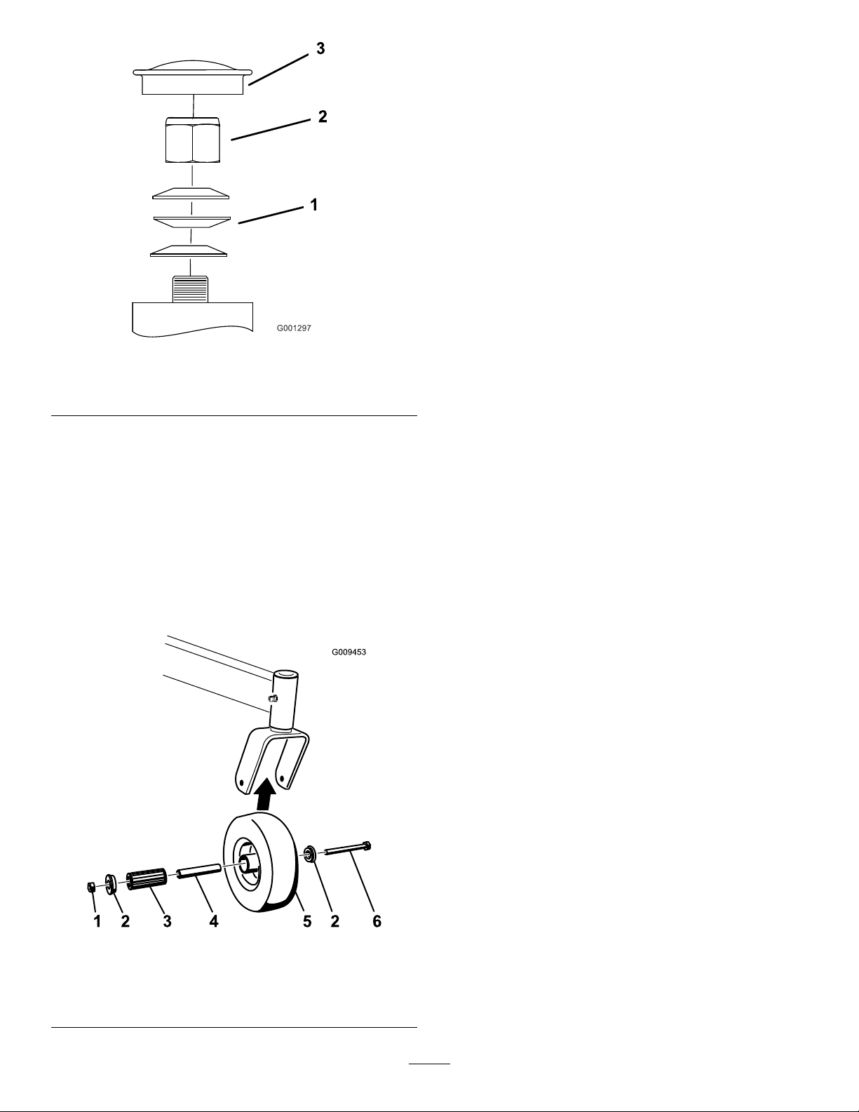
1.Springwashers
2.Locknut
Figure60
3.Dustcap
2.Removeonebushing,thenpullthespannerbushing
androllerbearingoutofthewheelhub(Figure61).
3.Removetheotherbushingfromthewheelhub,and
cleananygreaseanddirtfromthewheelhub(Figure
61).
4.Inspecttherollerbearing,bushings,spannerbushing
andtheinsideofthewheelhubforwear.
Note:Replaceanydefectiveorwornparts(Figure61).
5.Placeonebushingintothewheelhub(Figure61).
6.Greasetherollerbearingandspannerbushing,and
slidethemintothewheelhub(Figure61).
7.Placethesecondbushingintothewheelhub(Figure
61).
8.Installthecasterwheelintothecasterforkandsecure
itwiththewheelboltandlocknut(Figure61).
9.Tightenthelocknutuntilthespannerbushingbottoms
againsttheinsideofthecasterforks(Figure61).
10.Greasethettingonthecasterwheel.
ServicingtheCasterWheels andBearings
Thecasterwheelsrotateonarollerbearingsupportedbya
spannerbushing.Ifthebearingiskeptwelllubricated,wear
willbeminimal.Failuretokeepthebearingwelllubricated
willcauserapidwear.Awobblycasterwheelusuallyindicates
awornbearing.
1.Removethelocknutandwheelboltholdingthecaster
wheeltothecasterfork(Figure61).
ServicingtheClutch
CheckingtheClutch
ServiceInterval:Every200hours—Checktheclutch.
Iftheclutchtakestoomuchtimetostartthemowerdeckor
stopthemowerdeck,theclutchneedsadjustment.
Tochecktheclutch,performstepsC,EandFunderthe
procedureofRemovingtheClutchShim.
RemovingtheClutchShim
Thisunithasbeenbuiltwithaclutchthatcontainsabrake
shim.Whentheclutchbrakehasworntothepointwhere
theclutchnolongerengagesconsistently,theshimcanbe
removedtoextendtheclutchlife.
Figure61
1.Locknut
2.Wheelbolt5.Rollerbearing
3.Bushing
4.Spannerbushing
43
Page 44
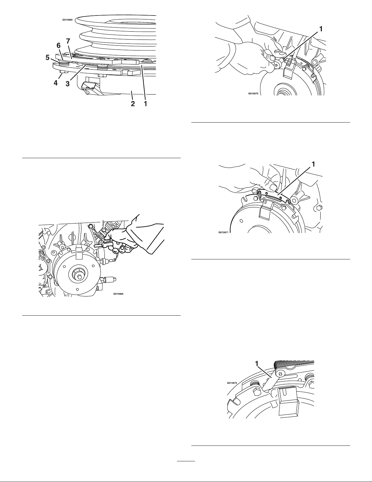
Figure62
1.Armature5.Brakespacer
2.Fieldshell6.Re-gapshim
3.Rotor7.Brakepole
4.Brake-mountingbolt
1.Stoptheengine,waitforallmovingpartstostop,
removethekey ,engagetheparkingbrake,andallow
themachinetocoolcompletelybeforestartingthese
instructions.
2.Usinganaircompressor,blowoutanydebrisfrom
underthebrakepoleandaroundthebrakespacers.
Figure64
1.Brake-mountingbolt
B.Usingneedlenosepliers,orbyhand,takeholdof
thetabandremovetheshim(Donotdiscardthe
shimuntiltheproperclutchfunctionhasbeen
conrmed).
Figure65
1.Shim
C.Usingapneumaticline,blowoutanydebris
fromunderthebrakepoleandaroundthebrake
spacers.
Figure63
3.Checktheconditionofthewireharnessleads,
connectors,andterminals.
Note:Cleanorrepairasnecessary.
4.Verifythat12Vispresentattheclutchconnectorwhen
thePTOswitchisengaged.
5.Measurethegapbetweentherotorandarmature.If
thegapisgreaterthan1mm(0.04inch),proceedwith
thefollowingsteps:
A.Loosenbothbrakemountingbolts1/2to1full
turnasshownbelow.
Note:Donotremovethebrakepolefromthe
eldshell/armature.Thebrakepolehasworn
tomatchthearmatureandneedstocontinueto
matchaftertheshimisremovedtoensureproper
braketorque.
D.Torqueeachbolt(M6x1)to13N-m(10ft-lb)
+/–0.7N-m(0.5ft-lb).
E.Usinga0.01inchthickfeelergauge,verifythat
agapispresentbetweentherotorandarmature
faceonbothsidesofthebrakepoleasshown.
Note:Duetothewaytherotorandarmature
faceswear(peaksandvalleys)itissometimes
difculttomeasurethetruegap.
Figure66
1.Feelergauge
44
Page 45
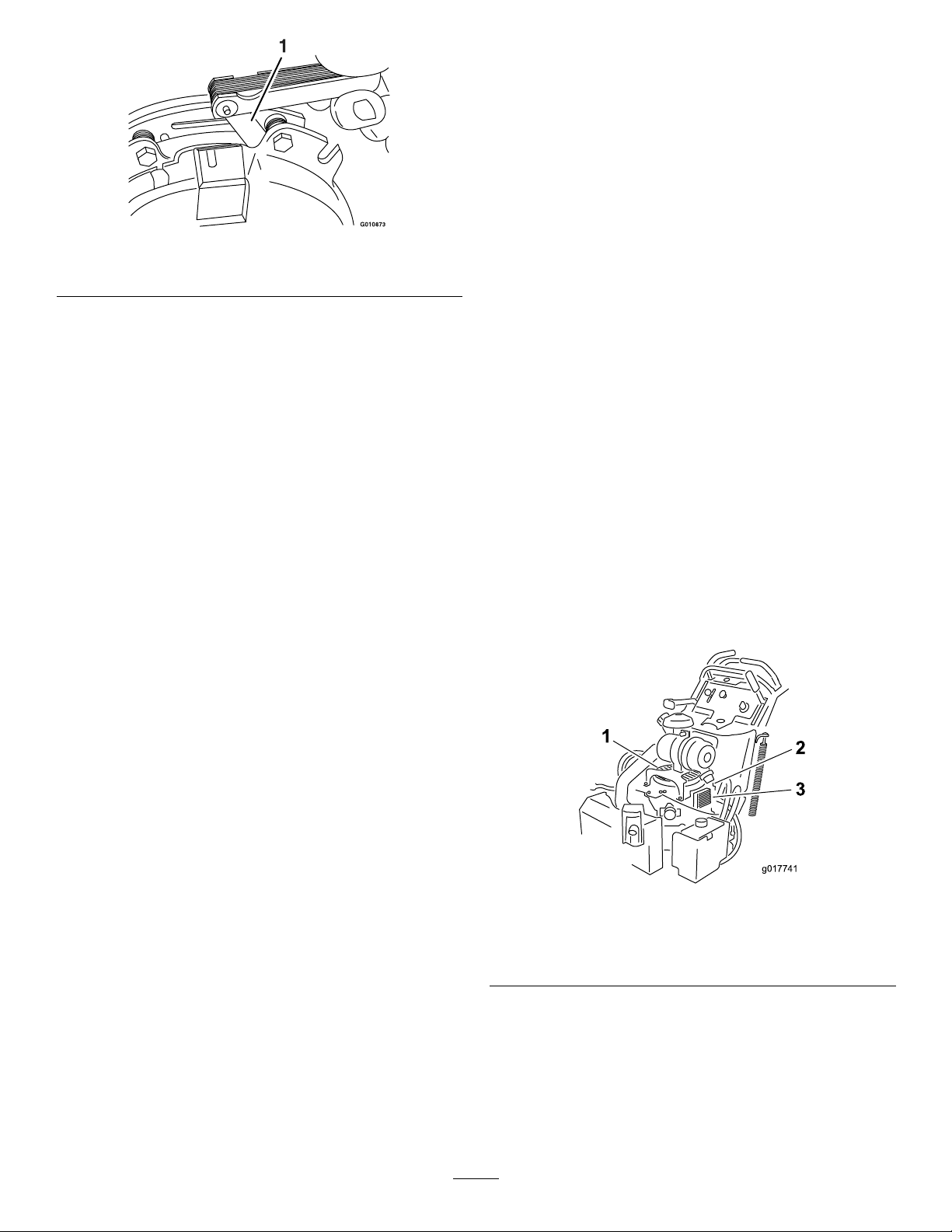
1.Feelergauge
g017741
1
2
3
Figure67
•Ifthegapislessthan0.25mm(0.01inch),
theninstalltheshim.
CoolingSystem
Maintenance
CleaningtheAir-IntakeScreen
ServiceInterval:Beforeeachuseordaily
Beforeeachuse,removeanybuildupofgrass,dirt,or
otherdebrisfromthecylinderandcylinderheadcooling
ns,airintakescreenontheywheelend,andthe
carburetor-governorleversandlinkage.Thiswillhelpensure
adequatecoolingandcorrectenginespeed,andwillreduce
thepossibilityofoverheatingormechanicaldamagetothe
engine.
•Ifthegapissufcient,proceedtothesafety
checkinstepF.
F.Performthefollowingsafetycheck:
i.Sitontheseat,andstarttheengine.
ii.Makesurethebladesdonotengagewith
thePTOswitchintheoffpositionand
theclutchdisengaged.
Iftheclutchdoesnotdisengage,install
theshim.
iii.EngageanddisengagethePTOswitch10
consecutivetimestoensurethattheclutch
isfunctioningproperly.
CheckingtheWheel-LugNuts
ServiceInterval:Aftertherst100hours—Checkthe
wheel-lugnuts.
Checkandtorquethewheellugnutsto115-142N-m(85-105
ft-lb).
CleaningtheCoolingSystem
ServiceInterval:Every100hours—Checkandcleanthe
enginecoolingnsandshrouds.
1.DisengagethePTOandsettheparkingbrake.
2.Stoptheengine,removethekey,andwaitforallmoving
partstostopbeforeleavingtheoperatingposition.
3.Removetheair-intakescreenandfanhousing(Figure
68).
4.Cleanthedebrisandgrassfromtheengineparts.
5.Installtheair-intakescreen,therecoilstarter,andthe
fanhousing(Figure68).
CheckingtheWheel-HubNuts
ServiceInterval:Aftertherst100hours—Checkthe
wheel-hubnuts.
Every500hours—Checkthewheel-hubnuts.
Checkandtorquethewheelhubnutsto211-260ft-lb
(286-352N-m).
45
1.Guardandengine
air-intakescreen
2.Fanhousing
Figure68
3.Engine-oilcooler
Page 46
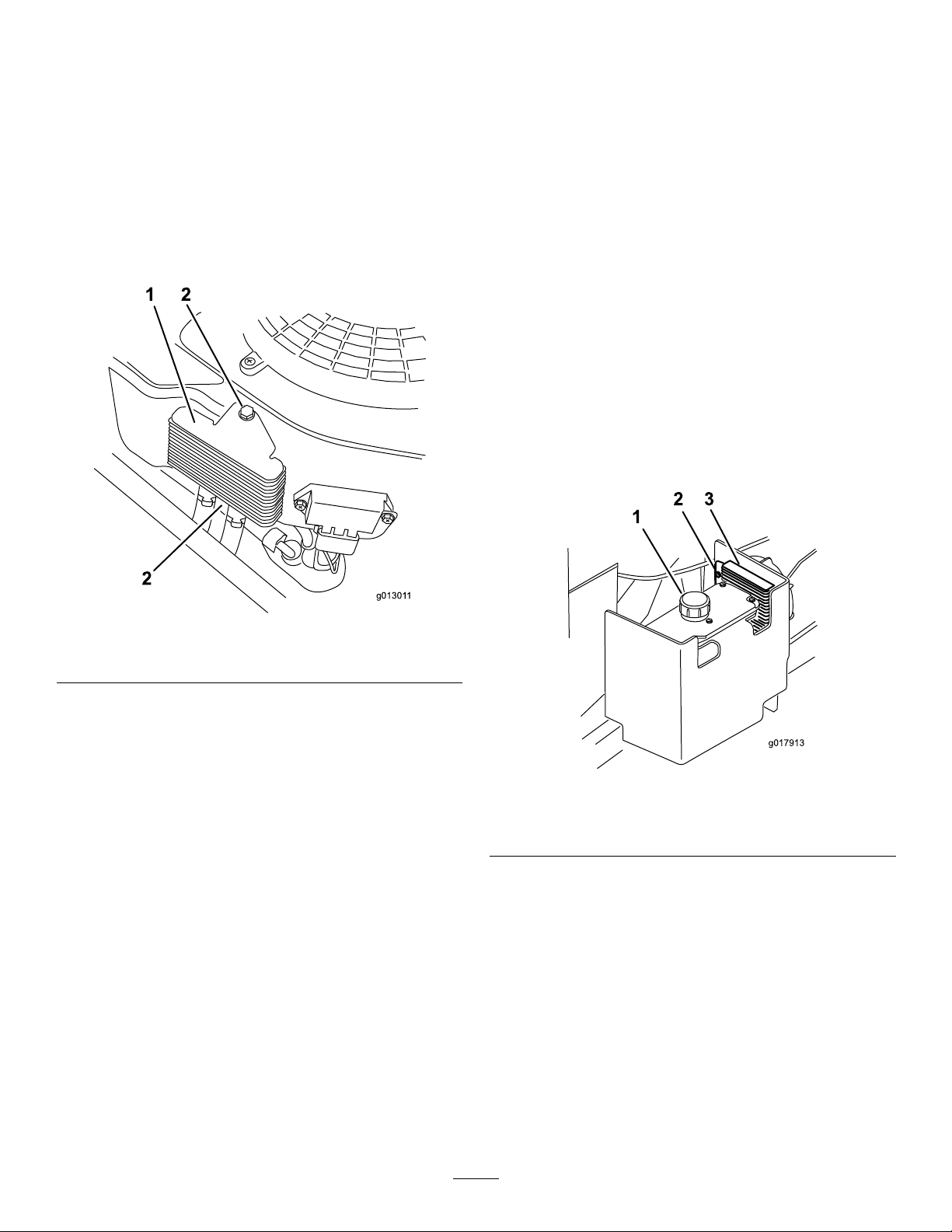
ServicingtheEngine-Oil
g01301 1
1 2
2
g017913
2 3
1
ServicingtheHydraulic-Oil
Cooler
ServiceInterval:Every200hours
1.Keeptheoilcoolerfreeofdebrisbycleaningthens
withabrush.
2.Removetheboltsholdingtheoilcoolertotheengine
housing(Figure68).
3.Cleantheinsideoftheoilcoolerwithabrush.
4.Installtheoilcoolertotheenginehousing.
Cooler
ServiceInterval:Every100hours—Servicethehydraulic-oil
coolerindirtyconditions(ifequipped).
1.Keepthehydraulic-oilcoolerfreeofdebrisbycleaning
thens.
2.Blowthehydraulic-oilcoolernstoremoveanyloose
drydebris.
3.Flushthecoolernswithwaterfromahosetoremove
anydirt.
Note:Asoftbrush(i.e.toothbrush)withasoapand
watersolutionmaybeusedtocleanthecooler.
Note:Donotuseapressurewasher.
Note:Highpressureandover-speedingthefanmay
causefanfailure.Usecarewithcompressedairtoavoid
over-speedingtheelectricfan.
Important:Donotdirectapressurewasheron
theelectricfan.
Figure69
1.Engine-oilcooler2.Bolts
CleaningtheHydraulic-Oil Cooler
ServiceInterval:Beforeeachuseordaily
Beforeeachuse,removeanybuildupofgrass,dirt,orother
debrisfromthehydraulic-oilcoolerandfan.Thiswillhelp
ensureadequatecooling,correctenginespeed,andreducethe
possibilityofoverheatingormechanicaldamagetotheengine.
Note:Highpressureandover-speedingthefanmay
causefanfailure.Usecarewithcompressedairtoavoid
over-speedingtheelectricfan.
Important:Donotdirectapressurewasheronthe
electricfan.
Figure70
1.Hydraulictank3.Hydraulic-oilcooler
2.Bolts
46
Page 47
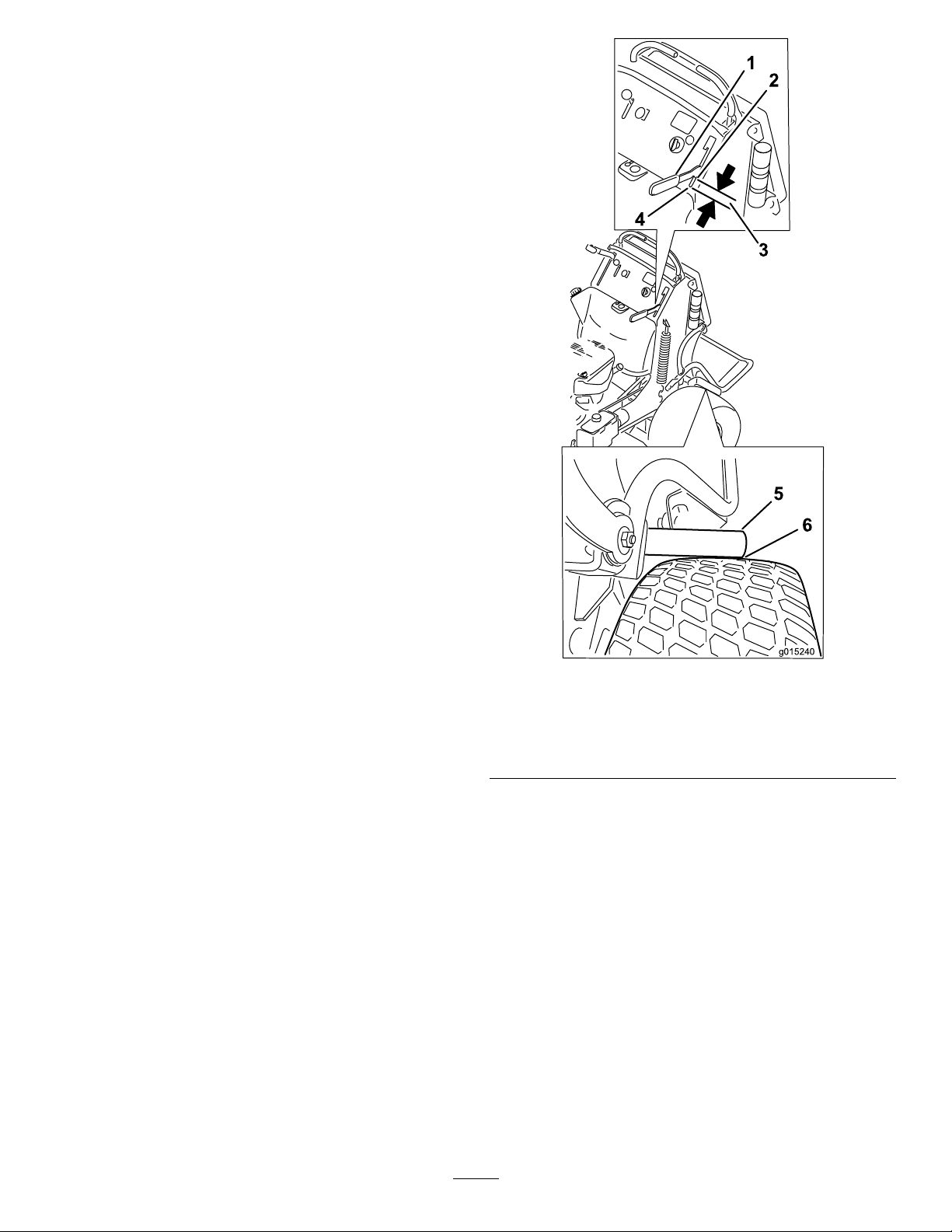
BrakeMaintenance
1
2
3
4
5
6
g015240
ServicingtheBrake
Beforeeachuse,checkthebrakesonalevelsurfaceandslope.
Alwayssettheparkingbrakewhenyoustopthemachineor
leaveitunattended.
Important:Iftheparkingbrakedoesnotholdsecurely,
anadjustmentisrequired.
CheckingtheParkingBrake
ServiceInterval:Beforeeachuseordaily
1.Parkthemachineonalevelsurface,disengagethePTO.
2.Stoptheengine,removethekey,andwaitforallmoving
partstostopbeforeleavingtheoperatingposition.
3.Releasethebrake.
Note:Thebrakebarsshouldliftoffthetiresandthe
handlevershouldtravelforwardtotheendoftheslot
inthecontrolpanel.
Note:Adjustthebrakeifneeded.
4.Engagethebrakeleveruntilthebrakebarsrstcontact
thetire(Figure71).
5.Measurethegapfromthefrontofthehandleverto
theendoftheslotinthecontrolpanelwhenthebrake
barcontactsthetire(Figure71).
Note:Thismeasurementneedstobe19mm(3/4
inch).
Note:Adjustthebrakeifneeded.
1.Handlever
2.Frontofhandlever
3.19mm(3/4inch)gap
Figure71
4.Frontofslot
5.Brakebar
6.Brakebarjusttouching
thetire
47
Page 48
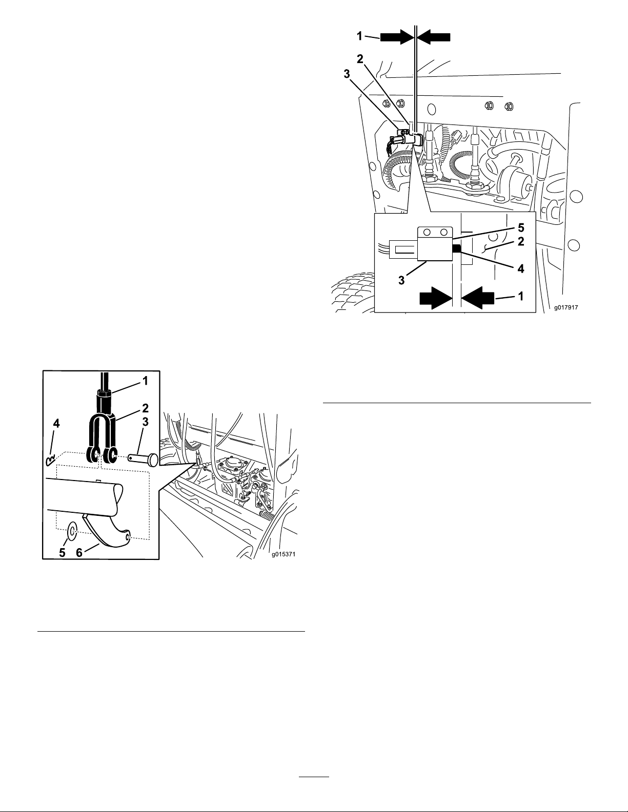
AdjustingtheBrakes
g015371
1
2
3
4
5 6
g017917
1
2
3
3
5
2
4
1
Iftheparkingbrakedoesnotholdsecurely ,anadjustment
isrequired.
1.Checkthebrakebeforeyouadjustit;refertoChecking
theParkingBrake(page47).
2.Parkthemachineonalevelsurface,disengagethe
PTO,andsettheparkingbrake.
3.Stoptheengine,removethekey,andwaitforallmoving
partstostopbeforeleavingtheoperatingposition.
4.Releasetheparkingbrake.
5.Toadjustthebrake,removethehairpincotterand
clevispinfromthelowerbrakeleverandyoke(Figure
72).
6.Loosenthejamnut(Figure72).
7.Rotatetheyoke(Figure72).
Note:Totightenthebrake,rotatetheyokeup.
Note:Toloosenthebrake,rotatetheyokedown.
8.Securetheyoketothelowerbrakeleverwiththe
hairpincotterandclevispin(Figure72).
9.Tightenthejamnut(Figure72).
10.Checkthebrakeoperationagain;refertoCheckingthe
ParkingBrake(page47).
1.3mm(1/8inch)gap
neededbetweenthe
switchandthebrakelever
2.Brakelever
3.Switch
Figure73
4.Switchbutton
5.Faceoftheswitch
1.Jamnut4.Hairpincotter
2.Yoke5.Flatwasher
3.Clevispin
Figure72
6.Lower-brakelever
11.Afterthebrakeisadjusted,checktheleverswitch
(Figure73).
12.Checkthegapbetweenthebrakeleverandthefaceof
theswitchasshowninFigure73.
Note:Thegapneedstobewithin3mm(1/8inch)
withthebrakeengaged.
13.Ifneeded,loosenthescrewsholdingtheswitchand
adjusttheswitch.
48
Page 49
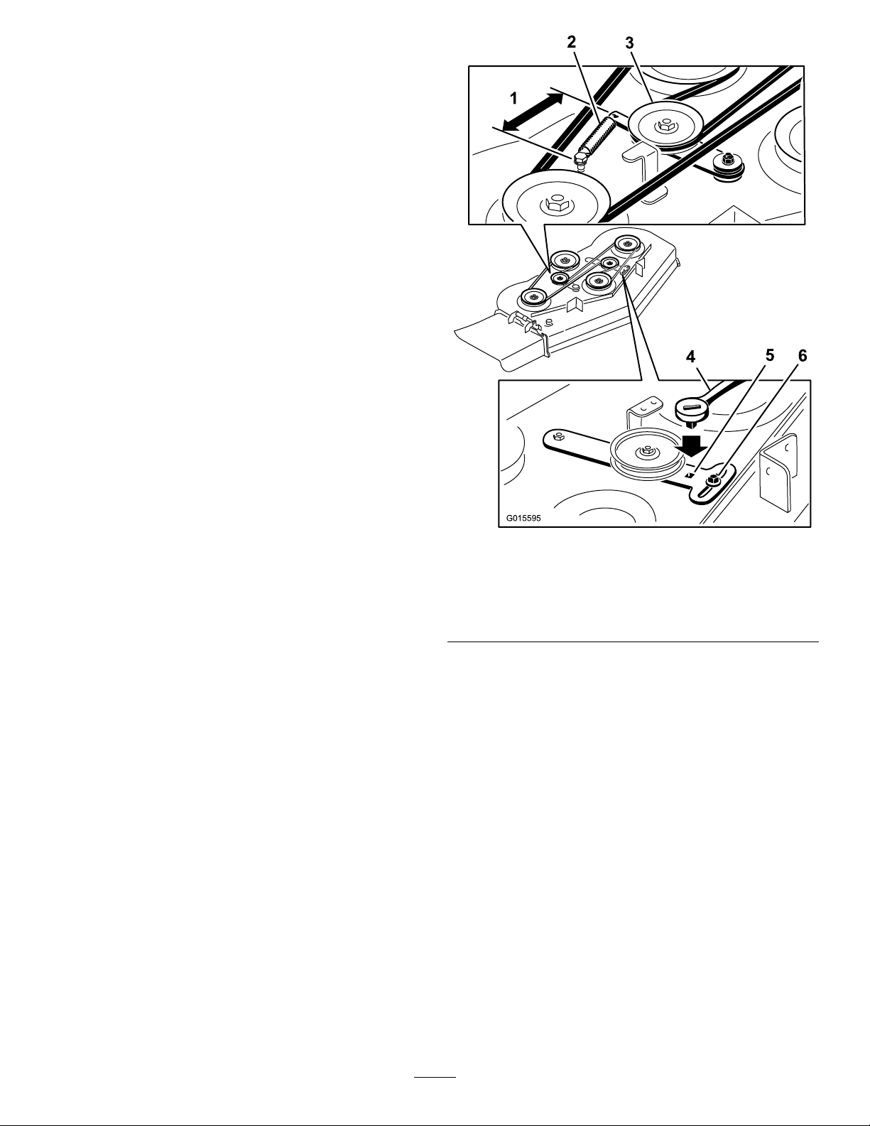
BeltMaintenance
G015595
ReplacingtheMower-Deck Belt
ServiceInterval:Every100hours—Checkthemower-deck
belt.
Squeakingwhenthebeltisrotating,thebladeisslippingwhen
cuttinggrass,frayedbeltedges,burnmarks,andcracksare
signsofaworndeckbelt.
Replacethedeckbeltifanyoftheseconditionsareevident.
1.DisengagethePTOandsettheparkingbrake.
2.Stoptheengine,removethekey,andwaitforallmoving
partstostopbeforeleavingtheoperatingposition.
3.Unlatchandremovethebeltcovers.
4.Loosenthefrontidlerpulleybylooseningthenut
(Figure74andFigure75).
5.Removethewornmowerbelt(Figure74andFigure
75).
6.Installthenewmowerbeltaroundthedeckpulleysand
clutchpulley(Figure74andFigure75).
7.Usingaratchetintheidlerarm,tightentheidlerpulley
untilthespringisstretched16.5cm(6.5inches)from
hooktohook(Figure74andFigure75).
8.Tightenthefrontidlerpulleybytighteningthenut
(Figure74andFigure75).
9.Installthebeltcoversontothecuttingunitandsecure
thelatches.
Figure74
1.16.5cm(6.5inches)from
hooktohook
2.Spring5.Squareholeforratchet
3.Spring-loadedidler
4.Ratchet
6.Nut
49
Page 50
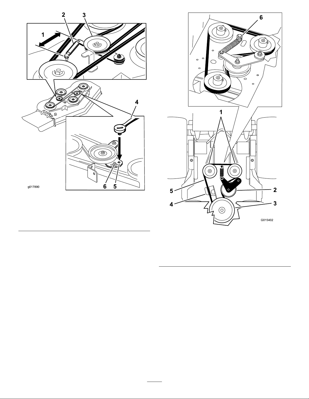
6 5
g017890
Figure75
G015402
1
2
3
5
4
6
1.16.5cm(6.5inches)from
hooktohook
2.Spring5.Squareholeforratchet
3.Spring-loadedidler
4.Ratchet
6.Nut
ReplacingthePump-driveBelt
ServiceInterval:Every100hours—Checkthepump-drive
belt.
1.DisengagethePTOandsettheparkingbrake.
2.Stoptheengine,removethekey,andwaitforallmoving
partstostopbeforeleavingtheoperatingposition.
3.Removethemower-deckbelt.
4.Tiltthemachine;refertoRaisingtheMowerforAccess
(page28).
5.Removetheshoulderbolt,thenut,andthewasher
fromtheenginedeckandconnectedspring(Figure76).
Figure76
1.Hydraulicpumps
2.Idlerpulley5.Pump-drivebelt
3.Clutchpulley6.Shoulderbolt,nut,and
4.Clutchretainer
washer
6.Removethepump-drivebelt(Figure76).
7.Installthenewbeltaroundtheclutchandthe2pump
pulleys.
8.Installthespringontotheshoulderboltandwasher,
andconnectittotheenginedeckwiththenut(Figure
76).
9.Lowerthemachinetotheoperatingposition.
10.Installthemower-deckbelt.
50
Page 51
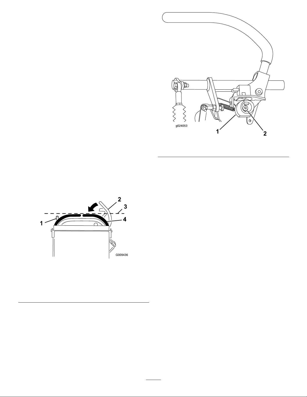
ControlsSystem
Maintenance
Adjustingthe Motion-Control-Handle Positions
AdjustingtheRightSideMotion-Control
Lever
Ifthemotion-controlleversdonotalignhorizontally ,adjust
therightsidemotion-controllever.
Note:Adjustthehorizontalalignmentbeforethefrontto
backalignment.
1.DisengagethePTO ,movetherightsidemotion-control
levertotheneutralposition,andsettheparkingbrake.
2.Stoptheengine,removethekey,andwaitforallmoving
partstostopbeforeleavingtheoperatingposition.
Figure78
1.Cam
2.Nut
3.Pushtherightmotion-controlleverdownoutofthe
neutral-lockedposition(Figure77).
4.Checkiftherightmotion-controlleveraligns
horizontallywiththeleftmotion-controllever(Figure
77).
Figure77
1.Leftmotion-controllever3.Checkthehorizontal
2.Rightmotion-controllever
intheneutral-locked
position
alignmenthere
4.Rightmotion-controllever
8.Adjustthecamuntilitalignswiththeleft
motion-controlleverandtightenthenutforthecam.
Note:Movingthecamclockwise(inthevertical
position)lowersthehandle,whilemovingit
counterclockwise(intheverticalposition)raisesthe
handle.
Important:Ensurethattheatportionofthe
camdoesnotgoaboveaverticalposition(rightor
left),oryoumaycausedamagetotheswitch.
5.Toadjusttherightmotion-controlleverhorizontally,
thecamneedstobeadjusted.
6.Releasethecushionfromtherearofthemachine.
7.Loosenthenutholdingthecam(Figure78).
51
Page 52
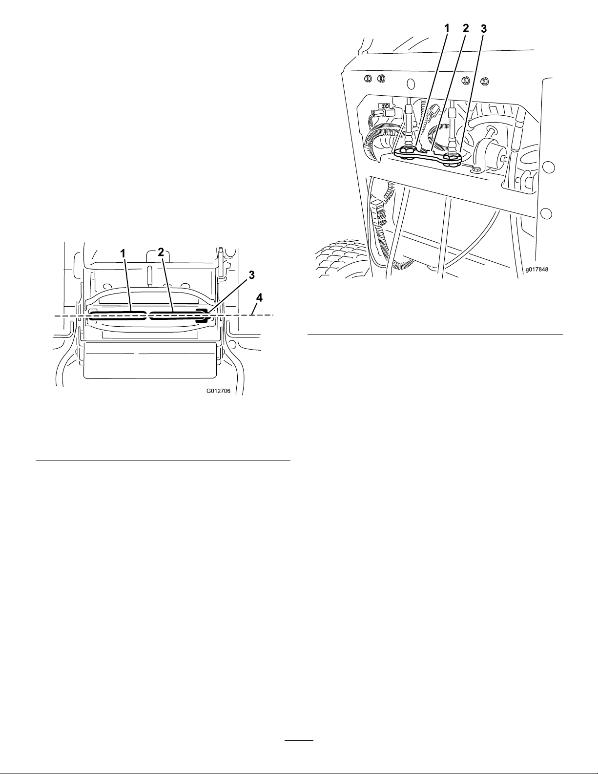
AdjustingtheNeutralPositionforthe
G012706
1
2
3
4
3
g017848
Motion-ControlLevers
Important:Ensurethetrackingofthemoweriscorrect
afteradjustingthemotion-controllevers.Adjustingthe
trackingandaligningthemotion-controlleversfrontto
backisthesameprocedure(Figure79).
Note:Adjustthehorizontalalignmentbeforethefrontto
backalignment.
Ifthemotion-controlleversdonotalignfronttoback,or
therightsidecontrolleverdoesnotmoveeasilyintothe
neutral-lockposition,adjustmentisrequired.
1.Afterthehorizontalalignmentisnished,checkthe
fronttobackalignmentbyslightlypushingthecontrol
leversforwardtotakeupanyslackinthelinkagefor
thecontrollevers(Figure79).
Figure80
Figure79
1.Leftmotion-controllever
2.Rightmotion-controllever4.Alignthecontrollevers
3.Neutral-lockedposition
fronttoback
2.Ensuretherightmotion-controllevermoveseasilyinto
theneutral-lockposition.
Note:Turnthecableadjustmentclockwiseto
movethemotion-controlhandleforward.Turn
thecableadjustmentcounterclockwisetomovethe
motion-controlhandlerearward.
3.Rotatethecableadjustmentonrightsidewhen
adjustmentisneeded.
1.Leftcableadjustment
2.Cablelock
3.Rightcableadjustment
Note:Adjustthecableadjustmentinquarter-turn
increments.
4.Aftertherightmotion-controllevermoveseasilyinto
theneutral-lockposition,adjusttheleftmotion-control
levertoalignwiththerightmotion-controllever.
5.Checkforpropertracking;refertoAdjustingthe
Tracking(page41).
6.Installthecablelockontothecable-adjustingnutsto
securetheadjustment(Figure80).
52
Page 53
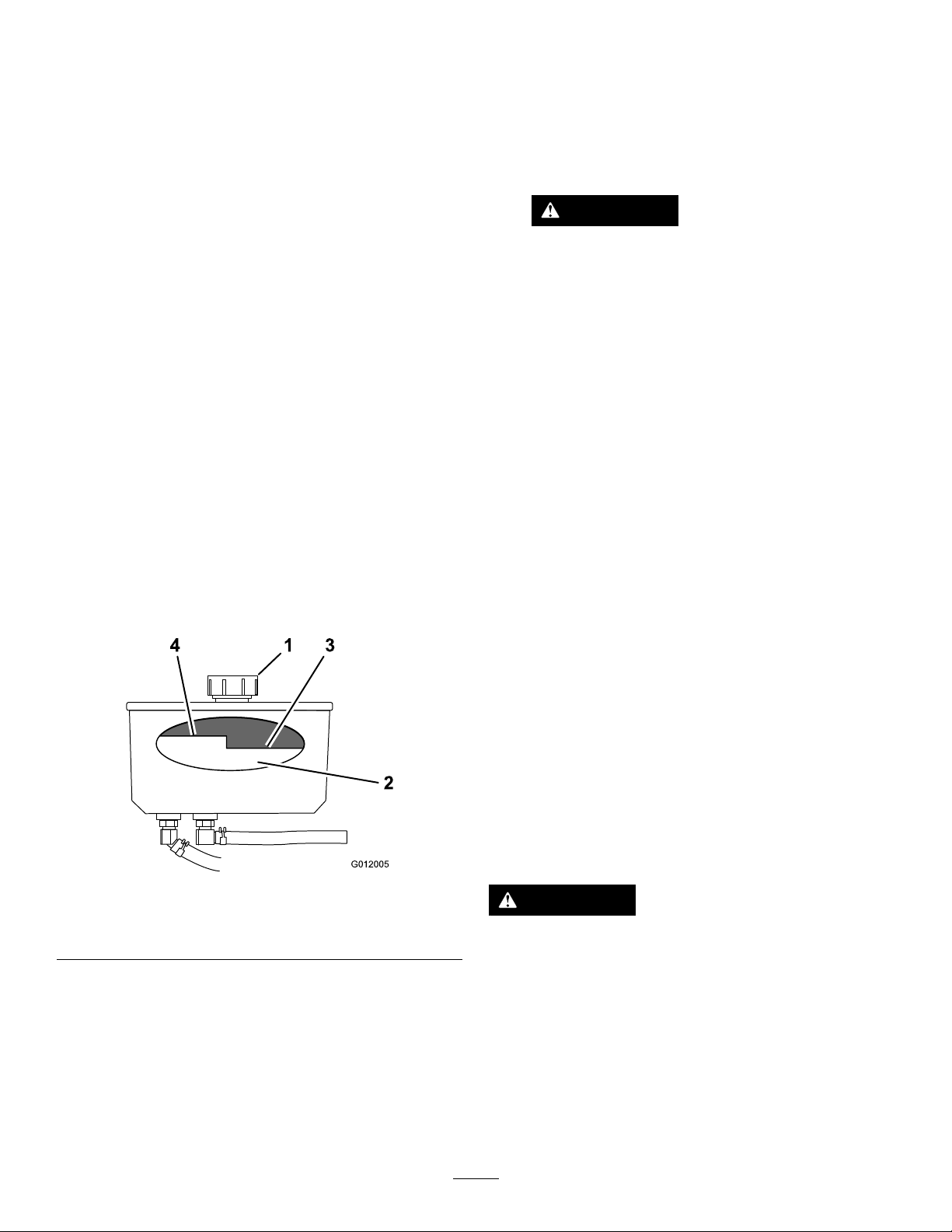
HydraulicSystem
G012005
4 1 3
2
Maintenance
ServicingtheHydraulic System
HydraulicOilType:Toro
orMobil
HydraulicSystemOilCapacity:2L(67oz)
Important:Useoilspecied.Otheruidscouldcause
systemdamage.
®
115W -50syntheticmotoroil.
®
HYPR-OIL
CheckingtheHydraulicFluid
ServiceInterval:Aftertherst8hours
Every50hours
Note:Thereare2waystocheckthehydraulicoil;whenthe
oiliswarm,orwhentheoiliscold.Thebafeinsidethetank
has2levelsdependingiftheoiliswarmorcold.
1.Positionthemachineonalevelsurface.
2.Disengagethepowertakeoff(PTO)andshutoffthe
engine.
3.Waitforallmovingpartstostopbeforeleavingthe
operatingpositionandthensettheparkingbrake.
4.Cleantheareaaroundthecapandthellerneckofthe
hydraulictank(Figure81).
™
500hydraulicoil
8.Checktheuidlevelwhiletheuidiswarm.
Note:Ifrequired,adduidtothereservoiruntilitis
betweenthehotlevelandthecoldlevel.
Note:Theuidlevelshouldbebelowthehotlevelof
thebafewhentheuidiswarm(Figure81).
9.Installthecaponthellerneck.
WARNING
Hydraulicuidescapingunderpressurecan
penetrateskinandcauseinjury.
•Ifhydraulicuidisinjectedintotheskin,
itmustbesurgicallyremovedwithinafew
hoursbyadoctorfamiliarwiththistype
ofinjury.Gangrenemayresultifthisis
notdone.
•Keepyourbodyandhandsawayfrom
pinholeleaksornozzlesthateject
high-pressurehydraulicuid.
•Usecardboardorpapertondhydraulic
leaks.
•Safelyrelieveallpressureinthehydraulic
systembeforeperforminganyworkonthe
hydraulicsystem.
•Makesureallhydraulic-uidhosesarein
goodcondition,andallthatthehydraulic
connectionsandttingsaretightbefore
applyingpressuretohydraulicsystem.
Figure81
1.Cap3.Colduidlevel—full
2.Bafe4.Hotuidlevel—full
5.Removethecapfromthellerneck(Figure81).
Note:Lookinsidetochecktheuidlevelinthe
reservoir.
6.Adduidtothereservoiruntilitreachesthecoldlevel
ofthebafe.
7.Runthemachineatlowidlefor15minutestoallow
anyairtopurgeoutofthesystemandwarmtheuid;
refertoStartingandStoppingtheEngine(page17).
ReplacingtheHydraulicFluid
ServiceInterval:Every250hours—Changethehydraulic
lterandhydraulicoilwhenusingMobil
1oil.
Every500hours/Yearly(whichevercomes
rst)—Changethehydrauliclterandhydraulicoil
whenusingToro
Note:Changethehydraulicuidmorefrequentlyinsevere
conditionsorinahotoperatingclimate.
®
HYPR-OIL
™
500hydraulicoil.
WARNING
Hothydraulicuidcancausesevereburns.
Allowthehydraulicuidtocoolbeforeperforming
anymaintenancetothehydraulicsystem.
1.DisengagethePTOandsettheparkingbrake.
2.Stoptheengineandwaitforallmovingpartstostop
beforeleavingtheoperatingposition.
3.Removehydraulic-reservoircap.
4.Locatethefronthydraulichoseunderthehydraulic
tank,andplaceadrainpanunderthetank(Figure82).
®
53
Page 54
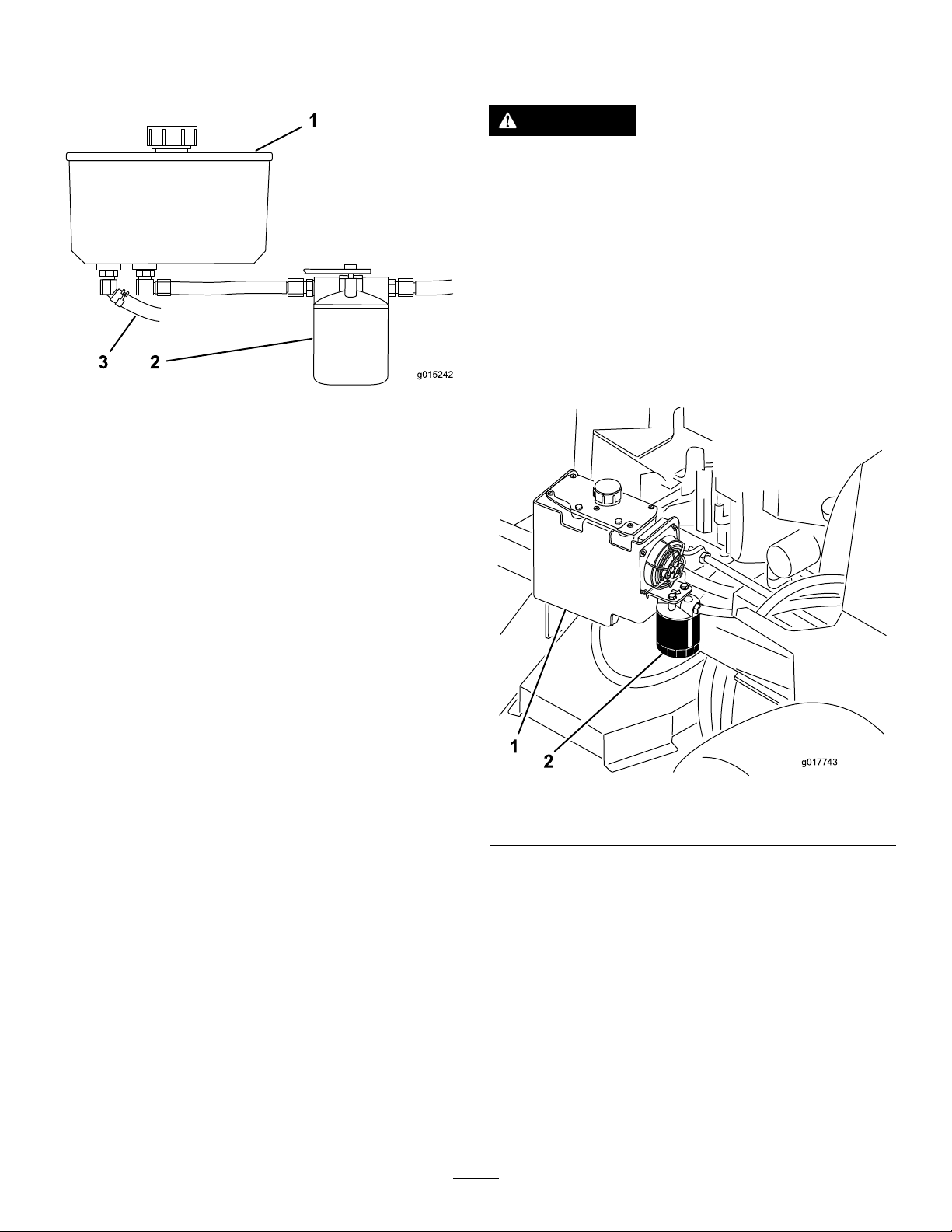
5.Loosenthehoseclampandmoveitdownthehose.
g015242
1
3 2
g017743
ReplacingtheHydraulicFilter
6.Removethefronthydraulichose,andallowtheuidto
runoutofthetank.
Figure82
1.Hydraulictank3.Fronthydraulichose
2.Hydrauliclter
7.Changethehydrauliclter;refertoReplacingthe
HydraulicFilter(page54).
ServiceInterval:Aftertherst8hours
WARNING
Hothydraulicuidcancausesevereburns.
Allowthehydraulicuidtocoolbeforeperforming
anymaintenancetothehydraulicsystem.
Important:Donotsubstitutewithanautomotiveoil
lter,orseverehydraulicsystemdamagemayresult.
1.DisengagethePTOandsettheparkingbrake.
2.Stoptheengineandwaitforallmovingpartstostop
beforeleavingtheoperatingposition.
3.Locatethelterandplaceadrainpanunderlter
(Figure83).
8.Connectthehydraulichoseunderthetank.
9.Adduidtothetankuntilitreachesthecoldbafe
ofthetank.
Important:Useoilspeciedorequivalent.Other
uidscouldcausesystemdamage.
10.Installthehydraulic-tankcap.
11.Starttheengineandletitrunforabout2minutesto
purgeairfromthesystem.
12.Stoptheengineandcheckforleaks.
Note:Ifoneorbothwheelswillnotdrive,referto
BleedingtheHydraulicSystem(page55).
13.Checktheleveloftheuidandadduid,ifrequired.
Note:Donotoverll.
Figure83
1.Hydraulictank
2.Hydrauliclter
4.Removetheoldlterandwipethelter-adaptergasket
surfaceclean(Figure84).
5.Applyathincoatofhydraulicuidtotherubbergasket
onthereplacementlter.
6.Installthereplacementhydrauliclterontothelter
adapter.
7.Turntheoillterclockwiseuntiltherubbergasket
contactsthelteradapter,thentightenthelteran
additional1/2turn(Figure84).
54
Page 55

Figure84
1.Hydrauliclter
2.Gasket
3.Adapter
8.Cleanupanyspilleduid.
9.Checktheuidinthereservoir,andadduidtothe
tankuntilitreachesthecoldbafeofthetank.
Important:Usetheoilspeciedorequivalent.
Otheruidscouldcausesystemdamage.
CheckingtheHydraulicLines
ServiceInterval:Every100hours
Checkhydraulichosesandhosesforleaks,loosettings,
kinkedhoses,loosemountingsupports,wear,general
weathering,andchemicaldeterioration.Makeanynecessary
repairsbeforeoperating.
Note:Keepareasaroundthehydraulicsystemcleanfrom
grassanddebrisbuildup.
Note:Extendedoperatingtimeathightemperaturesinahot
climatemayleadtodeteriorationofhosesandseals.Inspect
morefrequentlyinahotclimate,andchangethehydraulic
oilandltermorefrequently.
10.Starttheengineandletitrunforabout2minutesto
purgeairfromthesystem.
11.Stoptheengineandcheckforleaks.
Note:Ifoneorbothwheelswillnotdrive,referto
BleedingtheHydraulicSystem(page55).
12.Checktheleveloftheuidandadduid,ifrequired.
Note:Donotoverll.
BleedingtheHydraulicSystem
Thetractionsystemisself-bleeding,however,itmaybe
necessarytobleedthesystemifuidischangedorafterwork
isperformedonthesystem.
1.DisengagethePTOandsettheparkingbrake.
2.Stoptheengineandwaitforallmovingpartstostop
beforeleavingtheoperatingposition.
3.Raisetherearofthemachineontojackstandshigh
enoughtoraisethedrivewheelsofftheground.
4.Starttheengineandmovethethrottlecontroltothe
idleposition.
Note:Ifthedrivewheeldoesnotrotate,itispossible
toassistthepurgingofthesystembycarefullyrotating
thetireintheforwarddirection.
5.Checkthehydraulicuidlevelasitdrops,andadduid
asrequiredtomaintaintheproperlevel.
6.Repeatthisprocedurefortheoppositewheel.
7.Thoroughlycleantheareaaroundeachofthecharge
pumphousings.
55
Page 56
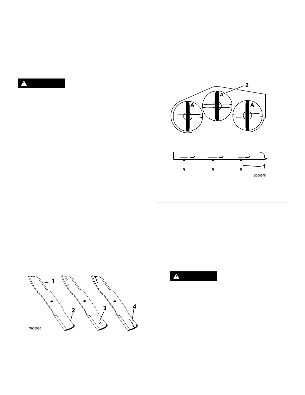
MowerDeck Maintenance
ServicingtheCuttingBlades
Toensureasuperiorqualityofcut,keepthebladessharp.
Forconvenientsharpeningandreplacement,youmaywant
tokeepextrabladesonhand.
WARNING
Awornordamagedbladecanbreak,andapiece
ofthebladecouldbethrownintotheoperator's
orbystanders’area,resultinginseriouspersonal
injuryordeath.
•Inspectthebladesperiodicallyforwearor
damage.
•Replaceawornordamagedblade.
BeforeInspectingorServicingthe
Blades
CheckingforBentBlades
1.DisengagethePTO ,movethemotion-controlleversto
theneutral-lockedposition,andsettheparkingbrake.
2.Stoptheengine,removethekey,andwaitforallmoving
partstostopbeforeleavingtheoperatingposition.
3.Rotatethebladesuntiltheendsfaceforwardand
backward.
4.Measurefromalevelsurfacetothecuttingedge,
positionA,oftheblades(Figure86).
Parkthemachineonalevelsurface,disengagethebladesand
settheparkingbrake.Turntheignitionkeytooff.Remove
thekey,anddisconnectthesparkplugwiresfromthespark
plugs.
InspectingtheBlades
ServiceInterval:Beforeeachuseordaily
1.Inspectthecuttingedges(Figure85).
2.Iftheedgesarenotsharporhavenicks,removeand
sharpentheblade;refertoSharpeningtheBlades(page
57).
3.Inspecttheblades,especiallyinthecurvedarea.
4.Ifyounoticeanycracks,wear,oraslotforminginthis
area,immediatelyinstallanewblade(Figure85).
Figure86
1.Measureherefromblade
tohardsurface
5.Rotatetheoppositeendsofthebladesforward.
6.Measurefromalevelsurfacetothecuttingedgeofthe
bladesatthesamepositionasinstep4above.
Note:Thedifferencebetweenthedimensions
obtainedinsteps4and5mustnotexceed3mm
(1/8inch).
Note:Ifthisdimensionexceeds3mm(1/8inch),the
bladeisbentandmustbereplaced.
2.PositionA
WARNING
Abladethatisbentordamagedcouldbreak
apartandcouldseriouslyinjureorkillyouor
bystanders.
•Alwaysreplacebentordamagedblade
withanewblade.
Figure85
1.Cuttingedge3.Wear/slotforming
2.Curvedarea4.Crack
•Donotleorcreatesharpnotchesinthe
edgesorsurfacesoftheblade.
56
Page 57
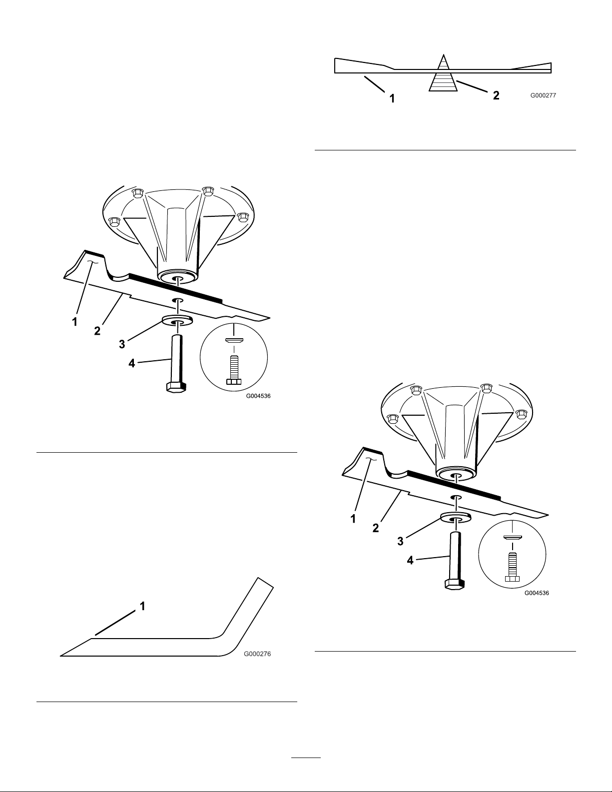
RemovingtheBlades
Bladesmustbereplacedifasolidobjectishit,ifthe
bladeisoutofbalance,orifthebladeisbent.T oensure
optimumperformanceandcontinuedsafetyconformance
ofthemachine,usegenuineTororeplacementblades.
Replacementbladesmadebyothermanufacturersmayresult
innonconformancewithsafetystandards.
1.Holdthebladeendusingaragorathickly-padded
glove.
Note:Ifthebladestaysinahorizontalposition,the
bladeisbalancedandcanbeused.
Figure89
1.Blade2.Balancer
2.Removethebladebolt,thecurvedwasher,andthe
bladefromthespindleshaft(Figure87).
Figure87
1.Sailareaoftheblade3.Curvedwasher
2.Blade4.Bladebolt
3.Ifthebladeisnotbalanced,lesomemetalofftheend
ofthesailareaonly(Figure87).
4.Repeatthisprocedureuntilthebladeisbalanced.
InstallingtheBlades
1.Installthebladeontothespindleshaft(Figure90).
Important:Thecurvedpartoftheblademustbe
pointingupwardtowardtheinsideofthemowerto
ensurepropercutting.
2.Installthespringdiskandbladebolt(Figure90).
Note:Thespring-diskconemustbeinstalledtoward
thebolthead(Figure90).
3.Torquethebladeboltto115to150N-m(85to
110ft-lb).
SharpeningtheBlades
1.Usealetosharpenthecuttingedgeatbothendsof
theblade(Figure88).
Note:Maintaintheoriginalangle.
Note:Thebladeretainsbalanceifthesameamount
ofmaterialisremovedfrombothcuttingedges.
Figure88
1.Sharpenattheoriginalangle
2.Checkthebalanceofthebladebyputtingitonablade
balancer(Figure89).
Figure90
1.Sailareaoftheblade3.Springdisk
2.Blade4.Bladebolt
57
Page 58
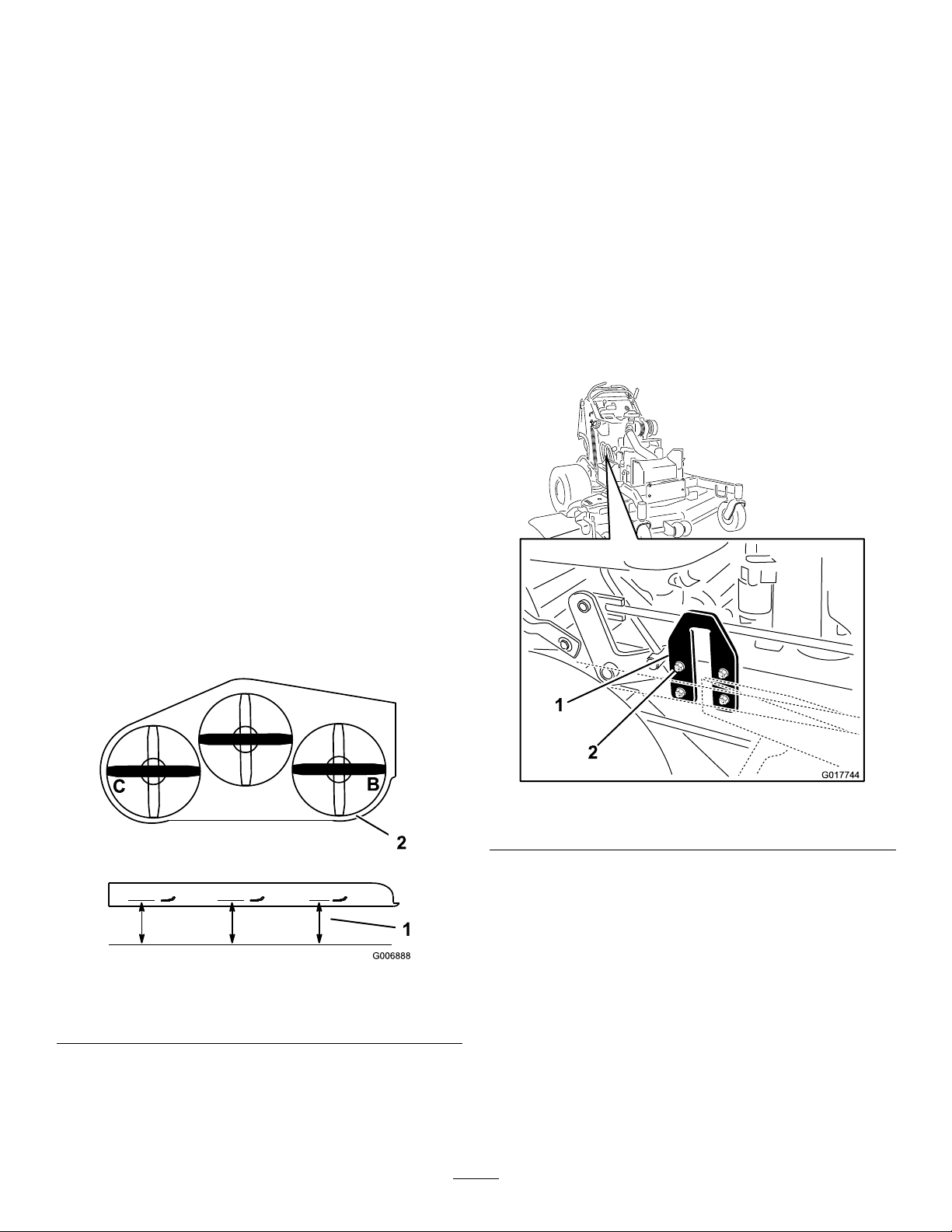
CorrectingtheMower
G017744
Quality-of-Cut
Ifonedeckbladecutslowerthantheother,correctitas
follows:
Note:Tireairpressureiscriticalintheseprocedures;make
surethereartireshavethecorrectpressure.
1.DisengagethePTOandsettheparkingbrake.
2.Stoptheengine,removethekey,andwaitforallmoving
partstostopbeforeleavingtheoperatingposition.
3.Disconnectthesparkplugwire(s)fromthespark
plug(s).
4.Adjustthetirepressureinthereartiresto83to97kPa
(12to14psi).
5.Checkthatthebladesandspindleshaftsarenotbent;
refertoCheckingforBentBlades(page56).
6.Settheheight-of-cuttothe7.6cm(3inches)position;
refertoAdjustingtheHeight-of-Cut(page24).
CheckingtheMowerDeckSide-to-Side
Height
ChangingtheMowerDeckSide-to-Side
Height
Changingtheside-to-sideheightisdonebyadjustingthe
rear-tirepressureandU-platesonthesideoftheenginedeck.
1.Changetherear-tirepressure.
Note:Dothistothecorrespondingsidethatneeds
adjustment.
2.LocatetheU-platesonthesideoftheenginedeck
(Figure92).
3.LoosentheU-plateon1side,andadjustitupordown
tomakethedifferencebetweenmeasurementsBandC
nomorethana6mm(1/4inch)asshowninFigure92.
4.ProceedtoCheckingtheMowerDeckFront-to-Rear
Pitch(page58).
1.Adjusttherear-tirepressure.
2.Ensurethatthebladesarenotbent;refertoChecking
forBentBlades(page56).
3.Positionthebladesside-to-side.
4.MeasureattheBandClocationsfromalevelsurface
tothecuttingedgeofbladetips(Figure91).
Figure91
1.Measurefromalevel
surface
2.Measurethebladeat
pointsBandC
Figure92
1.U-plate2.Nutsandbolts
CheckingtheMowerDeckFront-to-Rear
Pitch
1.Adjustthetirepressureinthereartirestothecorrect
specications.
2.Position1bladefront-to-rear.MeasureatAandB
locationsfromalevelsurfacetothecuttingedgeof
thebladetips(Figure93).
5.ThedifferencebetweenmeasurementsBandCshould
benomorethan6mm(1/4inch).
Note:Ifitisnotcorrect,refertoChangingtheMower
DeckSide-to-SideHeight(page58).
Note:Themowerbladeshouldbe6mm(1/4inch)
lowerinfrontatAthanintherearatB.
3.Rotatethebladesandrepeatforotherblades.
58
Page 59
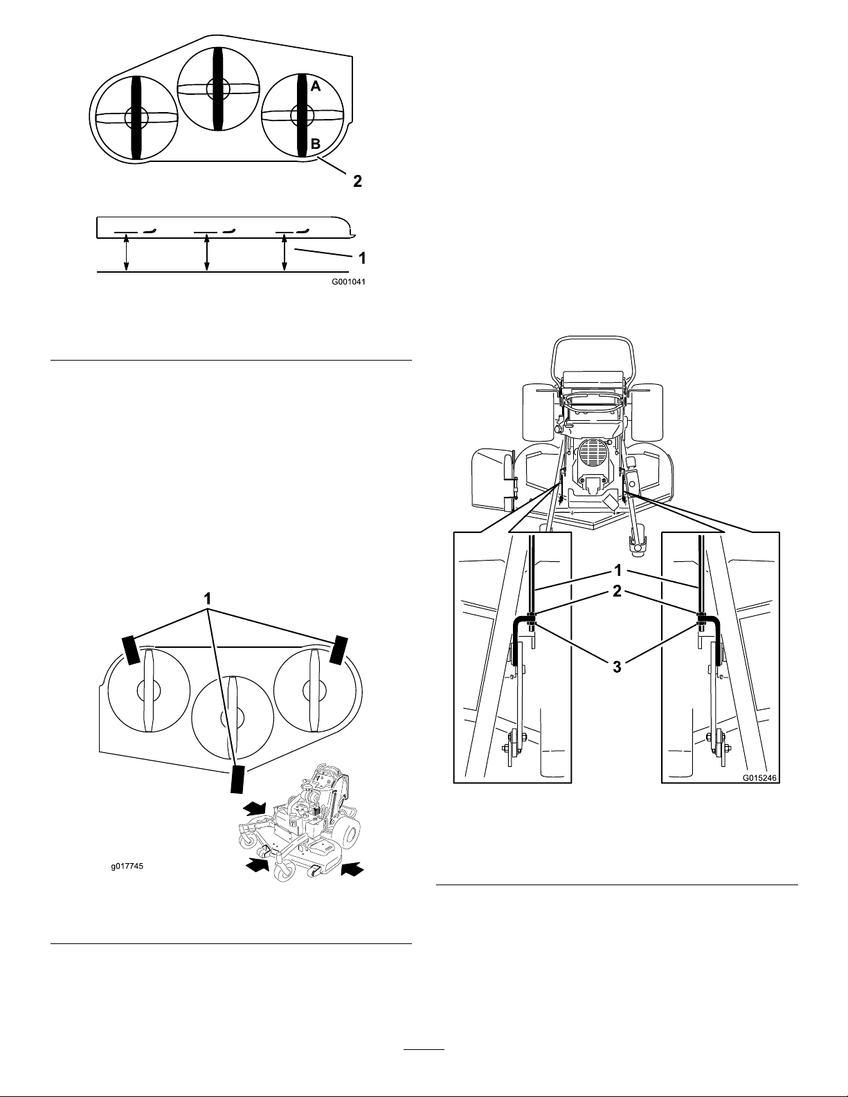
Figure93
g017745
G015246
1.Measurethebladeat
pointsAandB
2.Measurefromalevel
surface
4.Ifitisnotcorrect,refertoChangingtheMowerDeck
Front-to-RearPitch(page59).
ChangingtheMowerDeck
Front-to-RearPitch
4.For60-inchmowerdecks,loosenboththefrontand
rearnutsandliftlinksontheadjustmentrods(Figure
96).
Note:Theweightofthemowerdeckmustberesting
onall3ofthe2x4pieces(Figure95).
Note:Thebacklipofthemowerdeckisbuilt6mm
(1/4inch)lowerthanthefrontlipofthemowerdeck.
5.For60-inchmowerdecks,tightentheliftlinks(Figure
96).
6.Tightenboththefrontandrearnuts.
7.Checkthefront-to-rearpitchofthecuttingunit.
8.Ifthedimensionsarenotcorrect,adjustthefrontand
rearnutsoneithersidetogetthecorrectfront-to-rear
pitch(Figure95).
Changingthefront-to-rearpitchisdonebyadjustingthe
frontheight-of-cutposts.
1.Place3piecesof2x4woodunderthemowerdeckas
showninFigure94.
2.Standthe2x4piecesonthe4-inchpart.
Figure95
48and52-inchmowerdecks
1.Adjustmentrods3.Frontnuts
2.Rearnuts
Figure94
1.2x4pieceofwoodunderthemowerdeck
3.For48and52-inchmowerdecks,loosenboththefront
andrearnutsontheadjustmentrods(Figure95).
59
Page 60
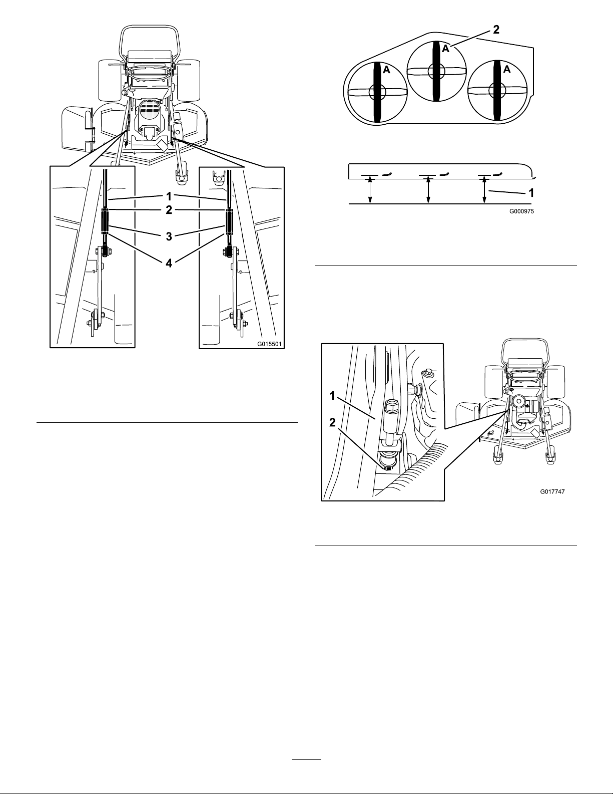
G015501
1
2
3
4
Figure97
G017747
1
2
Figure96
60-inchmowerdecks
1.Adjustmentrods
2.Rearnuts4.Frontnuts
3.Liftlink
MatchingtheHeight-of-Cut
1.Checkthereartirepressure.
2.Settheheight-of-cuttothe7.6cm(3inches)position;
refertoAdjustingtheHeight-of-Cut(page24).
3.Withthemachineonlevelsurface,positiononeblade
front-to-rear.
1.Measurefromalevel
surface
2.Measurethebladeatpoint
A
5.Ifitdoesnotmeasurecorrectly,locatetheheight-of-cut
rodontherightsideofthemachine(Figure98).
6.Adjusttheadjustmentboltuntilthebladetipsmatch
7.6cm(3inches)asshowninFigure98.
Figure98
1.Height-of-cutrod
2.Adjustmentbolt
4.MeasureatA,andfromalevelsurfacetothecutting
edgeofthebladetips(Figure97).
Note:Themeasurementshouldbe7.6cm(3inches).
60
Page 61
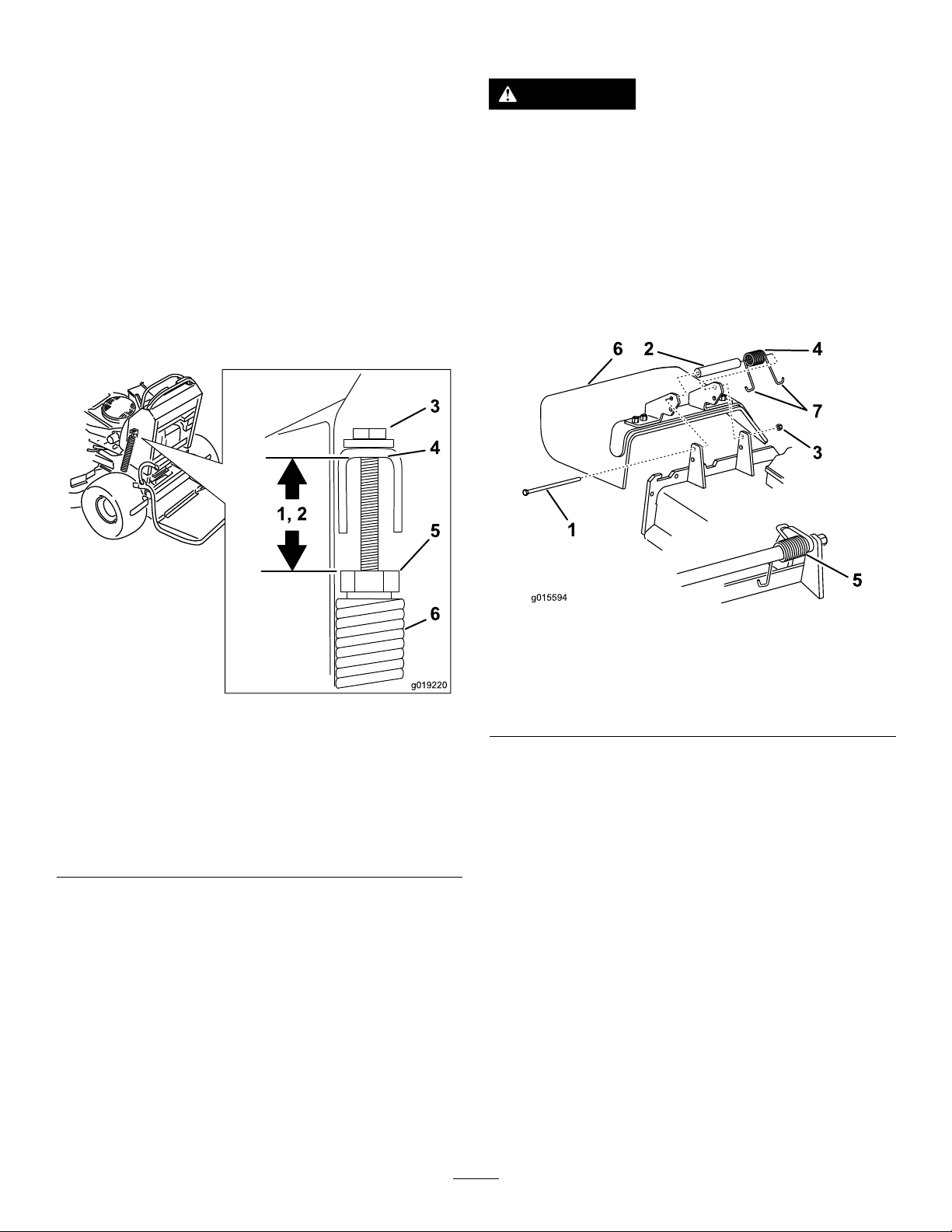
AdjustingtheDeck-LiftSpring
g019220
1, 2
3
4
5
6
g015594
1
6 2
4
7
3
5
ReplacingtheGrassDeector
Note:Adjustingthedeck-liftspringwillalterhowmuchthe
deckwilloatandhowmucheffortittakestoliftthedeck
whenusingtheheight-of-cuthandle.
1.Raisethedeck-liftleverandlockitintothetransport
position.
2.Checkthelengthbetweenthespringnutandthe
bottomoftheweldedU-bracket(Figure99).
3.Ensurethatthelengthisbetween47to50mm(1.8to
2inches)for48and52-inchmowerdecks,andbetween
43to46mm(1.7to1.8inches)for60-inchmower
decks(Figure99).
4.Ifneeded,adjustthedistancebyadjustingthebolton
topoftheU-bracket(Figure99).
WARNING
Anuncovereddischargeopeningcouldallowthe
lawnmowertothrowobjectsintheoperator'sor
bystander'sdirectionandresultinseriousinjury.
Also,contactwiththebladecouldoccur.
Donotoperatethelawnmowerunlessyouinstall
acoverplate,amulchplate,grassdeector,or
bagger.
1.Removethelocknut,bolt,spring,andspacerholding
thedeectortothepivotbrackets(Figure100).
Figure99
1.Lengthisbetween47to
50mm(1.8to2inches)
for48and52-inchmower
decks
2.Lengthisbetween43to
46mm(1.7to1.8inches)
for60-inchmowerdecks
3.Adjustmentbolt
4.Bottomofthewelded
U-bracket
5.Springnut
6.Deck-liftspring
5.Repeatthisprocedurefortheoppositedeck-liftspring.
Figure100
1.Bolt
2.Spacer6.Grassdeector
3.Locknut
4.Spring
5.Spring(installed)
7.J-hookendofthespring
2.Removethedamagedorworngrassdeector.
3.Placethespacerandthespringontothegrassdeector.
4.Place1Jendofthespringbehindthedeckedge.
Note:Makesure1Jendofspringisinstalledbehind
deckedgebeforeinstallingtheboltasshowninFigure
100.
5.Installtheboltandthenut.
6.Place1J-hookendofthespringaroundthegrass
deector(Figure100).
Important:Thegrassdeectormustbeable
torotate.Liftthedeectoruptothefullopen
position,andensurethatitrotatesintothefull
downposition.
61
Page 62

Cleaning
Storage
CleaningundertheMower
ServiceInterval:Beforeeachuseordaily
Removethegrassbuildupunderthemowerdaily.
1.DisengagethePTO ,movethemotion-controlleversto
theneutral-lockedpositionandsettheparkingbrake.
2.Stoptheengine,removethekey,andwaitforallmoving
partstostopbeforeleavingtheoperatingposition.
3.Raisethefrontofthemachineandusejackstandsto
supportthemower.
DisposingoftheWaste
Engineoil,batteries,hydraulicoil,andenginecoolantare
pollutantstotheenvironment.Disposeoftheseaccordingto
yourstateandlocalregulations.
CleaningandStorage
1.Disengagethepowertakeoff(PTO),settheparking
brake,turntheignitionkeytooff,andremovethekey.
2.Removegrassclippings,dirt,andgrimefromthe
externalpartsoftheentiremachine,especiallythe
engine.
Important:Y oucanwashthemachinewithamild
detergentandwater.Donotpressurewashthe
machine.Avoidexcessiveuseofwater,especially
nearthedrivesystemandengine.Pressure
washingcanforcedirtandwaterintocriticalparts,
suchasspindlebearingsandelectricalswitches.
3.Cleandirtandchafffromtheoutsideoftheengine
cylinderheadnsandblowerhousing.
4.Checkthebrake;refertoServicingtheBrakeinBrake
Maintenance(page47).
5.Servicetheaircleaner;refertoServicingtheAir
CleanerinEngineMaintenance(page32).
6.Greasethemachine;refertoGreasingandLubrication
inLubrication(page30).
7.Changetheengineoil;refertoServicingtheEnginein
EngineMaintenance(page32).
8.Checkthetirepressure;refertoCheckingtheTire
PressureinDriveSystemMaintenance(page41).
9.Forlong-termstorage:
A.Addstabilizer/conditioneradditivetofuelinthe
tank.
B.Runenginetodistributeconditionedfuelthrough
thefuelsystem(5minutes).
C.Stopengine,allowtocoolanddrainthefueltank;
refertoServicingtheFuelTankinFuelSystem
Maintenance(page36),oroperateengineuntil
itstops.
D.Restartengineandrununtilitstops.Repeat,on
Chokeuntilenginewillnotrestart.
E.Disposeoffuelproperly .Recycleasperlocal
codes.
Note:Donotstorestabilizer/conditioned
gasolineover90days.
10.Removethesparkplug(s)andcheckitscondition;refer
toServicingtheSparkPluginEngineMaintenance
(page32).Withthesparkplug(s)removedfromthe
engine,pourtwotablespoonsofengineoilintothe
sparkplughole.Nowusethestartertocrankthe
engineanddistributetheoilinsidethecylinder.Install
thesparkplug(s).Donotinstallthewireonthespark
plug(s).
11.Checkandtightenallbolts,nuts,andscrews.Repairor
replaceanypartthatisdamagedordefective.
62
Page 63

12.Paintallscratchedorbaremetalsurfaces.Paintis
availablefromyourAuthorizedServiceDealer.
13.Storethemachineinaclean,drygarageorstoragearea.
Removethekeyfromtheignitionswitchandkeepit
inamemorableplace.Coverthemachinetoprotect
itandkeepitclean.
63
Page 64

Troubleshooting
Problem
Theenginewillnotstart,startshard,or
failstokeeprunning.
Theenginelosespower.
Theengineoverheats.
PossibleCauseCorrectiveAction
1.Thefueltankisemptyorshut-offvalve
closed.
2.Thesparkplugwireislooseor
disconnected.
3.Thesparkplugispitted,fouled,orthe
gapisincorrect.
4.Theaircleanerisdirty .
5.Thereisdirtinthefuellter.5.Replacethefuellter.
6.Thereisdirt,water,orstalefuelisin
thefuelsystem.
7.Thegapbetweenthesafetyinterlock
switchesisnotcorrect.
1.Theengineloadisexcessive.1.Reducethegroundspeed.
2.Theaircleanerisdirty .
3.Theoillevelinthecrankcaseislow.3.Addoiltothecrankcase.
4.Thecoolingnsandairpassages
abovetheengineareplugged.
5.Theventholeinthefuelcapisplugged.5.Cleanorreplacethefuelcap.
6.Dirtisinthefuellter.6.Replacethefuellter.
7.Dirt,water,orstalefuelisinthefuel
system.
1.Theengineloadisexcessive.1.Reducethegroundspeed.
2.Theoillevelinthecrankcaseislow.2.Addoiltothecrankcase.
3.Thecoolingnsandairpassages
abovetheengineareplugged.
1.Fillfueltankwithgasolineandopen
valve
2.Installwireonsparkplug.
3.Installanew,correctlygappedspark
plug.
4.Servicetheaircleanerelement.
6.ContactanAuthorizedServiceDealer.
7.ContactanAuthorizedServiceDealer.
2.Cleantheaircleanerelement.
4.Removetheobstructionfromthe
coolingnsandairpassages.
7.ContactanAuthorizedServiceDealer.
3.Removetheobstructionfromthe
coolingnsandairpassages.
Themachinedoesnotdrive.
Thereisanabnormalvibration.
Themachineisproducinganuneven
cuttingheight.
1.Thebypassvalveisnotclosedtight.1.Tightenthebypassvalve.
2.Thedriveorpumpbeltisworn,loose
orbroken.
3.Thedriveorpumpbeltisoffapulley.3.Changethebelt.
4.Theidlerspringisbrokenormissing.4.Replacethespring.
5.Thehydraulicuidlevelislowortoo
hot.
1.Thecuttingblade(s)is/arebentor
unbalanced.
2.Theblademountingboltisloose.2.Tightentheblademountingbolt.
3.Theenginemountingboltsareloose.3.Tightentheenginemountingbolts.
4.Theenginepulley,idlerpulley ,orblade
pulleyisloose.
5.Theenginepulleyisdamaged.
6.Thebladespindleisbent.
7.Themotormountislooseorworn.
1.Thecuttingblade(s)is/arenotsharp.1.Sharpentheblade(s).
2.Thecuttingblade(s)is/arebent.2.Installnewcuttingblade(s).
3.Themowerdeckisnotlevel.
4.Theundersideofmowerisdirty.4.Cleantheundersideofthemower.
5.Thetirepressureisnotcorrect.5.Adjustthetirepressure.
6.Thebladespindleisbent.
2.Changethebelt.
5.Addhydraulicuidtothereservoiror
letitcooldown.
1.Installnewcuttingblade(s).
4.Tightentheappropriatepulley.
5.ContactanAuthorizedServiceDealer.
6.ContactanAuthorizedServiceDealer.
7.ContactanAuthorizedServiceDealer.
3.Levelthemowerdeckfromside-to-side
andfront-to-rear.
6.ContactanAuthorizedServiceDealer.
64
Page 65

Problem
PossibleCauseCorrectiveAction
Thecuttingbladesdonotrotate.
ThemalfunctionIndicatorLight(MIL)
comeson.
1.Thedrivebeltisworn,looseorbroken.
2.Thedrivebeltisoffpulley.
3.Themowerdeckbeltisworn,loose
orbroken.
4.Themowerdeckbeltcameoffapulley.
5.Theidlerspringisbrokenormissing.5.Replacethespring.
1.Theengineistoohot.
2.Thereisoldgasinthegastank.2.Usenewgas.
3.Thefuelshut-offvalveisnotopen
completely.
4.Theaircleanerisdirty .4.Makesurethattheaircleanerand
5.Thebatteryisnotcharged.
6.Incorrectfuelltersarebeingusedor
thefuelltersaredirty.
7.Theconnectionstothesensors
electroniccontrolunit(ECU)andfuel
injectorsarenotsecuredproperly .
8.Thereislowvoltagefromthebattery.
9.Afuseisblown.9.Checkandreplaceanyblownfuses.
1.Checkthebelttension.
2.Installthedrivebeltandcheckthe
adjustingshaftsandbeltguidesfor
correctposition.
3.Installanewmowerdeckbelt.
4.Installthemowerdeckbeltandcheck
theidlerpulley ,idlerarm,andspring
forthecorrectpositionandfunction.
1.Turntheengineoffandletitcool.
3.Openthefuelshut-offvalve.
precleanerareclean.Replaceif
necessary.
5.Chargeorreplacethebattery.
6.ContactanAuthorizedServiceDealer.
7.ContactanAuthorizedServiceDealer.
8.Ensureagood12voltbatteryisbeing
usedandisfullycharged.
65
Page 66
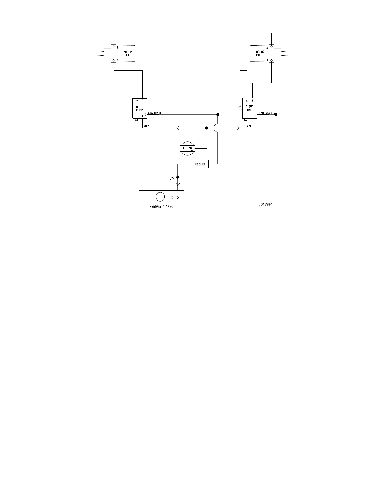
Schematics
g017891
COOLER
HydraulicSchematic(Rev .A)
66
Page 67
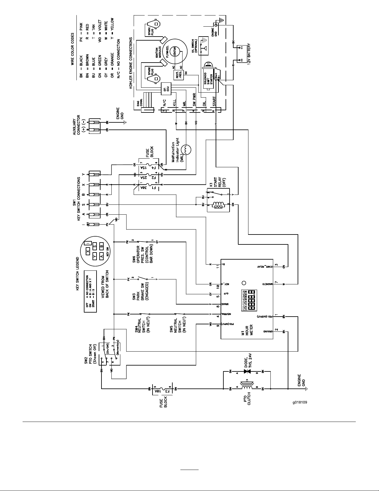
g018109
ElectricalSchematic(Rev .A)
67
Page 68

TheToroTotalCoverageWarranty
ALimitedWarranty(seewarrantyperiodsbelow)Contractor
Landscape
Equipment
(LCE)
ConditionsandProductsCovered
TheToroCompanyanditsafliate,T oroWarrantyCompany ,pursuanttoanagreement
betweenthem,jointlypromisetotheoriginalpurchasertorepairtheT oroProducts
listedbelowifdefectiveinmaterialsorworkmanship.
Thefollowingtimeperiodsapplyfromthedateofpurchasebytheoriginalowner:
ProductsWarrantyPeriod
21in.Mowers2yearsResidentialUse
1yearCommercialUse
4
•Engines
Honda–2years
Kawasaki–3years
30in.Mowers2yearsResidentialUse
1yearCommercialUse
4
•Engines
Mid-SizeWalk-BehindMowers
4
•Engines
GrandStand
4
•Engines
•Frame
®
ZMaster
•Engines
2000SeriesMowers
4
•Frame
®
ZMaster
•Engines
•Frame
ZMaster
•Engines
®
4
4
3000SeriesMowers
5000SeriesMowers
®
Mowers
Kawasaki–3years
2years
Kawasaki–3years
5yearsor1,200hours
3years
Lifetime(originalowneronly)
4yearsor500hours
3years
Lifetime(originalowneronly)
5yearsor1,200hours
3years
Lifetime(originalowneronly)
5yearsor1,200hours
KohlerCommand–2years
KohlerEFI–3years
•Frame
®
ZMaster
•Engines
6000SeriesMowers
4
•Frame
®
ZMaster
•Engines
7000SeriesMowers
4
•Frame
Lifetime(originalowneronly)
5yearsor1,200hours
Kawasaki–3years
Lifetime(originalowneronly)
5yearsor1,200hours
2years
Lifetime(originalowneronly)
AllMowers
•Battery90daysPartsandLabor
1yearPartsonly
•BeltsandTires90days
•Attachments1year
1
Residentialusemeansuseoftheproductonthesamelotasyourhome.Useatmorethanone
locationisconsideredcommercialuseandthecommercialwarrantywouldapply .
2
Whicheveroccursrst.
3
LifetimeFrameW arranty-Ifthemainframe,consistingofthepartsweldedtogethertoformthe
tractorstructurethatothercomponentssuchastheenginearesecuredto,cracksorbreaksin
normaluse,itwillberepairedorreplaced,atT oro'soption,underwarrantyatnocostforpartsand
labor.Framefailureduetomisuseorabuseandfailureorrepairrequiredduetorustorcorrosion
arenotcovered.
4
SomeenginesusedonT oroProductsarewarrantedbytheenginemanufacturer .
1
1
2
3
2
3
2
3
2
3
2
3
2
3
InstructionsforObtainingWarrantyService
IfyouthinkthatyourT oroProductcontainsadefectinmaterialsorworkmanship,
followthisprocedure:
1.ContactanyAuthorizedToroServiceDealertoarrangeserviceattheir
dealership.T olocateadealerconvenienttoyou,refertotheYellowPagesof
yourtelephonedirectory(lookunder“LawnMowers”)oraccessourwebsite
atwww.Toro.com.Y oumayalsocallthenumberslistedinitem#3tousethe
24-hourT oroDealerlocatorsystem.
2.Bringtheproductandyourproofofpurchase(salesreceipt)totheService
Dealer.Thedealerwilldiagnosetheproblemanddetermineifitiscovered
underwarranty.
3.IfforanyreasonyouaredissatisedwiththeServiceDealer’sanalysisorwith
theassistanceprovided,contactusat:
RLCCustomerCareDepartment
ToroWarrantyCompany
811 1LyndaleAvenueSouth
Bloomington,MN55420-1 196
888-865-5676(U.S.Customers)
888-865-5691(Canadacustomers)
OwnerResponsibilities
YoumustmaintainyourToroProductbyfollowingthemaintenanceprocedures
describedintheOperator'sManual.Suchroutinemaintenance,whetherperformedby
adealerorbyyou,isatyourexpense.
ItemsandConditionsNotCovered
Thereisnootherexpresswarrantyexceptforspecialemissionsystemcoverage
andenginewarrantycoverageonsomeproducts.Thisexpresswarrantydoesnot
coverthefollowing:
•Costofregularmaintenanceserviceorparts,suchaslters,fuel,lubricants,oil
changes,sparkplugs,airltersbladesharpeningorwornblades,cable/linkage
adjustments,orbrakeandclutchadjustments
•Componentsfailingduetonormalwear
•Anyproductorpartwhichhasbeenalteredormisusedorneglectedandrequires
replacementorrepairduetoaccidentsorlackofpropermaintenance
•Pickupanddeliverycharges
•RepairsorattemptedrepairsbyanyoneotherthananAuthorizedT oroService
Dealer
•Repairsnecessaryduetofailuretofollowrecommendedfuelprocedure(consult
Operator'sManualformoredetails)
–Removingcontaminantsfromthefuelsystemisnotcovered
–Useofoldfuel(morethanonemonthold)orfuelwhichcontainsmorethan
10%ethanolormorethat15%MTBE
–Failuretodrainthefuelsystempriortoanyperiodofnon-useoverone
month
GeneralConditions
AllrepairscoveredbythesewarrantiesmustbeperformedbyanAuthorizedT oro
ServiceDealerusingT oroapprovedreplacementparts.
NeitherTheToroCompanynorToroWarrantyCompanyisliableforindirect,
incidentalorconsequentialdamagesinconnectionwiththeuseoftheT oro
Productscoveredbythiswarranty,includinganycostorexpenseofproviding
substituteequipmentorserviceduringreasonableperiodsofmalfunctionor
non-usependingcompletionofrepairsunderthiswarranty .
Allimpliedwarrantiesofmerchantability(thattheproductistforordinaryuse)
andtnessforuse(thattheproductistforaparticularpurpose)arelimitedto
thedurationoftheexpresswarranty.
Somestatesdonotallowexclusionsofincidentalorconsequentialdamages,
orlimitationsonhowlonganimpliedwarrantylasts,sotheaboveexclusions
andlimitationsmaynotapplytoyou.
Thiswarrantygivesyouspeciclegalrights,andyoumayalsohaveotherrights
whichvaryfromstatetostate.
CountriesOtherthantheUnitedStatesorCanada
CustomerswhohavepurchasedT oroproductsoutsidetheUnitedStatesorCanadashouldcontacttheirToroDistributor(Dealer)toobtainguaranteepoliciesforyourcountry,
province,orstate.IfforanyreasonyouaredissatisedwithyourDistributor'sserviceorhavedifcultyobtainingguaranteeinformation,contacttheT oroimporter.Ifallother
remediesfail,youmaycontactusatT oroWarrantyCompany.
AustralianConsumerLaw:AustraliancustomerswillnddetailsrelatingtotheAustralianConsumerLaweitherinsidetheboxoratyourlocalT oroDealer.
374-0252RevF
 Loading...