

Page 1
FormNo.3424-645RevA
ZMaster
®
Professional7500-D
SeriesRidingMower
With96inTURBOFORCE
Mower
ModelNo.74096—SerialNo.400000000andUp
®
RearDischarge
Registeratwww.T oro.com.
OriginalInstructions(EN)
*3424-645*A
Page 2

ItisaviolationofCaliforniaPublicResourceCode
Section4442or4443touseoroperatetheengineon
anyforest-covered,brush-covered,orgrass-covered
landunlesstheengineisequippedwithaspark
arrester,asdenedinSection4442,maintainedin
effectiveworkingorderortheengineisconstructed,
equipped,andmaintainedforthepreventionofre.
Theenclosedengineowner'smanualissupplied
forinformationregardingtheUSEnvironmental
ProtectionAgency(EPA)andtheCaliforniaEmission
ControlRegulationofemissionsystems,maintenance,
andwarranty.Replacementsmaybeorderedthrough
theenginemanufacturer.
GrossorNetTorque:Thegrossornettorque
ofthisenginewaslaboratoryratedbytheengine
manufacturerinaccordancewiththeSocietyof
AutomotiveEngineers(SAE)J1940orJ2723.As
conguredtomeetsafety,emission,andoperating
requirements,theactualenginetorqueonthisclass
ofmowerwillbesignicantlylower.Pleasereferto
theenginemanufacturer’sinformationincludedwith
themachine.
ThisproductcomplieswithallrelevantEuropean
directives;fordetails,pleaseseetheseparateproduct
specicDeclarationofConformity(DOC)sheet.The
grossornettorqueofthisenginewaslaboratory
ratedbytheenginemanufacturerinaccordancewith
theSocietyofAutomotiveEngineers(SAE)J1940
orJ2723.Asconguredtomeetsafety,emission,
andoperatingrequirements,theactualenginetorque
onthisclassofmowerwillbesignicantlylower.
Pleaserefertotheenginemanufacturer’sinformation
includedwiththemachine.
WARNING
CALIFORNIA
Proposition65Warning
Dieselengineexhaustandsomeofits
constituentsareknowntotheStateof
Californiatocausecancer,birthdefects,
andotherreproductiveharm.
Batteryposts,terminals,andrelated
accessoriescontainleadandlead
compounds,chemicalsknownto
theStateofCaliforniatocause
cancerandreproductiveharm.Wash
handsafterhandling.
Useofthisproductmaycauseexposure
tochemicalsknowntotheStateof
Californiatocausecancer,birthdefects,
orotherreproductiveharm.
Pleaserefertotheenginemanufacturer’sinformation
includedwiththemachine.
©2018—TheToro®Company
8111LyndaleAvenueSouth
Bloomington,MN55420
Contactusatwww.Toro.com.
2
PrintedintheUSA
AllRightsReserved
Page 3
Introduction
Thisrotary-blade,ridinglawnmowerisintendedtobe
usedbyresidentialhomeownersorprofessional,hired
operators.Itisdesignedprimarilyforcuttinggrasson
well-maintainedlawnsonresidentialorcommercial
properties.Itisnotdesignedforcuttingbrushorfor
agriculturaluses.
Readthisinformationcarefullytolearnhowtooperate
andmaintainyourproductproperlyandtoavoid
injuryandproductdamage.Youareresponsiblefor
operatingtheproductproperlyandsafely .
YoumaycontactTorodirectlyatwww.T oro.com
forproductsafetyandoperationtrainingmaterials,
accessoryinformation,helpndingadealer,orto
registeryourproduct.
Wheneveryouneedservice,genuineToroparts,or
additionalinformation,contactanAuthorizedService
DealerorToroCustomerServiceandhavethemodel
andserialnumbersofyourproductready.Figure1
identiesthelocationofthemodelandserialnumbers
ontheproduct.Writethenumbersinthespace
provided.
seriousinjuryordeathifyoudonotfollowthe
recommendedprecautions.
g000502
Figure2
Safety-alertsymbol
Thismanualuses2wordstohighlightinformation.
Importantcallsattentiontospecialmechanical
informationandNoteemphasizesgeneralinformation
worthyofspecialattention.
Important:Withyourmobiledevice,youcan
scantheQRcode(ifequipped)ontheserial
numberdecaltoaccesswarranty,parts,andother
productinformation.
Figure1
1.Modelandserialnumberlocation
g235670
ModelNo.
SerialNo.
Thismanualidentiespotentialhazardsandhas
safetymessagesidentiedbythesafety-alertsymbol
(Figure2),whichsignalsahazardthatmaycause
3
Page 4

Contents
Safety.......................................................................5
GeneralSafety...................................................5
SlopeIndicator...................................................6
SafetyandInstructionalDecals..........................7
ProductOverview...................................................14
Controls...........................................................15
HorizonDisplayMonitor................................15
Specications..................................................17
BeforeOperation.................................................17
BeforeOperationSafety...................................17
AddingFuel......................................................18
PerformingDailyMaintenance..........................19
BreakinginaNewMachine..............................19
UsingtheRolloverProtectionSystem
(ROPS).........................................................19
UsingtheSafety-InterlockSystem....................20
PositioningtheSeat..........................................21
UnlatchingtheSeat..........................................21
ChangingtheSeatSuspension.........................21
DuringOperation.................................................22
DuringOperationSafety...................................22
OperatingtheParkingBrake.............................24
LoweringtheWingDecks.................................24
OperatingtheMowerBlade-ControlSwitch
(PTO)............................................................25
StartingtheEngine...........................................25
ShuttingOfftheEngine.....................................26
RaisingandLockingtheWingDecks................26
UsingtheMotion-ControlLevers.......................27
DrivingtheMachine..........................................27
AdjustingtheHeightofCut...............................29
AdjustingtheAnti-ScalpRollers........................30
AdjustingtheSkids...........................................31
OperatingwiththeOverheatSensor.................31
OperatingTips.................................................31
AfterOperation....................................................32
AfterOperationSafety......................................32
TransportingtheMachine.................................33
Maintenance...........................................................35
RecommendedMaintenanceSchedule(s)...........35
Pre-MaintenanceProcedures..............................36
MaintenanceSafety..........................................36
Lubrication..........................................................36
GreasingtheMachine.......................................36
LubricatingtheGreaseFittings.........................37
LubricatingtheDriveU-JointsandSplined
SlipJoint.......................................................37
LubricatingtheCaster-WheelHubs..................38
EngineMaintenance...........................................39
EngineSafety...................................................39
ServicingtheAirCleaner..................................39
ServicingtheEngineOil....................................40
FuelSystemMaintenance...................................42
DrainingtheFuelFilter/WaterSeparator...........42
ChangingtheWaterSeparator.........................42
InspectingtheEngine-ValveClearance............43
CheckingtheFuelLinesand
Connections..................................................43
ElectricalSystemMaintenance...........................43
ElectricalSystemSafety...................................43
ServicingtheBattery.........................................43
ServicingtheFuses..........................................46
DriveSystemMaintenance..................................46
ReleasingtheDriveWheelRelease
Valves...........................................................46
AdjustingtheTracking......................................47
CheckingtheTirePressure...............................48
CheckingtheWheelLugNuts...........................48
AdjustingtheCaster-PivotBearing...................48
ServicingtheGearbox......................................49
CoolingSystemMaintenance..............................50
CoolingSystemSafety.....................................50
CheckingtheCoolingSystem...........................50
CleaningtheRadiator.......................................50
ChangingtheEngineCoolant...........................50
BrakeMaintenance.............................................51
AdjustingtheParkingBrake..............................51
BeltMaintenance................................................53
InspectingtheBelts..........................................53
ReplacingtheMowerBelts...............................53
CheckingtheAlternator-BeltTension................54
ControlsSystemMaintenance.............................55
AdjustingtheControl-HandlePosition..............55
AdjustingtheMotion-ControlLinkage...............55
AdjustingtheMotion-ControlDamper...............56
HydraulicSystemMaintenance...........................57
HydraulicSystemSafety...................................57
ServicingtheHydraulicSystem........................57
MowerDeckMaintenance....................................59
LevelingtheMowerDeck..................................59
ServicingtheCuttingBlades.............................61
Cleaning..............................................................63
CleaningtheEngineandExhaustSystem
Area..............................................................63
CleaningtheMachineandMower
Deck..............................................................63
DisposingofWaste...........................................63
Storage...................................................................64
StorageSafety..................................................64
CleaningandStoringtheMachine....................64
Troubleshooting......................................................65
Schematics.............................................................67
4
Page 5

Safety
Thismachinehasbeendesignedinaccordancewith
ANSIB71.4-2012.
GeneralSafety
Thisproductiscapableofamputatinghandsand
feetandofthrowingobjects.Alwaysfollowallsafety
instructionstoavoidseriouspersonalinjury.
Usingthisproductforpurposesotherthanitsintended
usecouldprovedangeroustoyouandbystanders.
•Alwayskeeptherollbarinthefullyraisedand
lockedpositionandusetheseatbelt.
•Donotoperatethemachineneardrop-offs,
ditches,embankments,water,orotherhazards,or
onslopesgreaterthan15degrees.
•Readandunderstandthecontentsofthis
Operator’sManualbeforestartingtheengine.
•Donotputyourhandsorfeetnearmoving
componentsofthemachine.
•Donotoperatethemachinewithoutallguards
andothersafetyprotectivedevicesinplaceand
workingonthemachine.
•Keepchildrenandbystandersoutoftheoperating
area.Neverallowchildrentooperatethemachine.
•Stopthemachine,shutofftheengine,andremove
thekeybeforeservicing,fueling,orunclogging
themachine.
Improperlyusingormaintainingthismachinecan
resultininjury .T oreducethepotentialforinjury,
complywiththesesafetyinstructionsandalwayspay
attentiontothesafety-alertsymbol,whichmeans
Caution,Warning,orDanger—personalsafety
instruction.Failuretocomplywiththeseinstructions
mayresultinpersonalinjuryordeath.
Youcanndadditionalsafetyinformationwhere
neededthroughoutthismanual.
5
Page 6
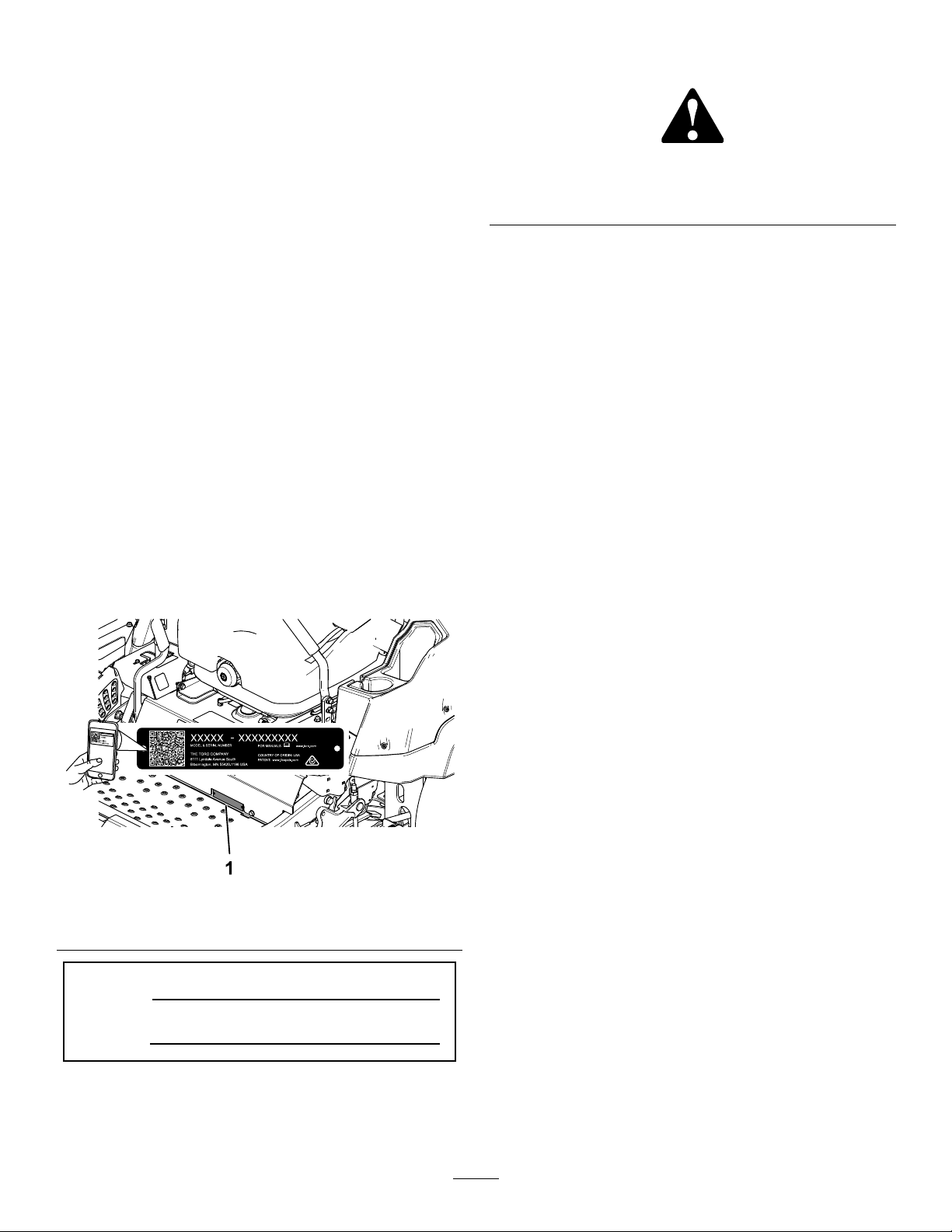
SlopeIndicator
Figure3
Youmaycopythispageforpersonaluse.
1.Themaximumslopeyoucanoperatethemachineonis15degrees.Usetheslopecharttodeterminethedegreeofslopeof
hillsbeforeoperating.Donotoperatethismachineonaslopegreaterthan15degrees.Foldalongtheappropriateline
tomatchtherecommendedslope.
2.Alignthisedgewithaverticalsurface,atree,building,fencepole,etc.
3.Exampleofhowtocompareslopewithfoldededge
6
g011841
Page 7
SafetyandInstructionalDecals
Safetydecalsandinstructionsareeasilyvisibletotheoperatorandarelocatednearanyarea
ofpotentialdanger.Replaceanydecalthatisdamagedormissing.
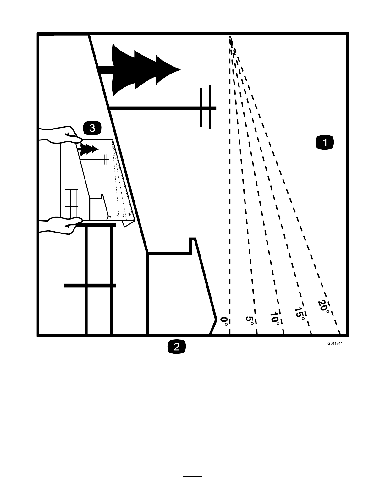
BatterySymbols
Someorallofthesesymbolsareonyourbattery .
decalbatterysymbols
1.Explosionhazard
6.Keepbystandersasafe
distanceawayfromthe
battery.
2.Nore,opename,or
smoking
7.Weareyeprotection;
explosivegasescan
causeblindnessandother
injuries.
3.Causticliquid/chemical
burnhazard
8.Batteryacidcancause
blindnessorsevereburns.
4.Weareyeprotection.9.Flusheyesimmediately
withwaterandgetmedical
helpfast.
5.ReadtheOperator's
Manual.
10.Containslead;donot
discard
Manufacturer'sMark
1.Indicatesthebladeisidentiedasapartfromtheoriginal
machinemanufacturer.
decal99-8936
99-8936
1.Machinespeed4.NEUTRAL
2.FAST5.REVERSE
3.SLOW
decal106-5517
106-5517
decaloemmarkt
1.Warning—donottouchthehotsurface.
1.Grease
1.Donotstephere.
decal58-6520
58-6520
decal93-6687
93-6687
7
Page 8
decal112-9028
112-9028
1.Warning—stayawayfrommovingparts;keepallguardsin
place.
decal116-5988
116-5988
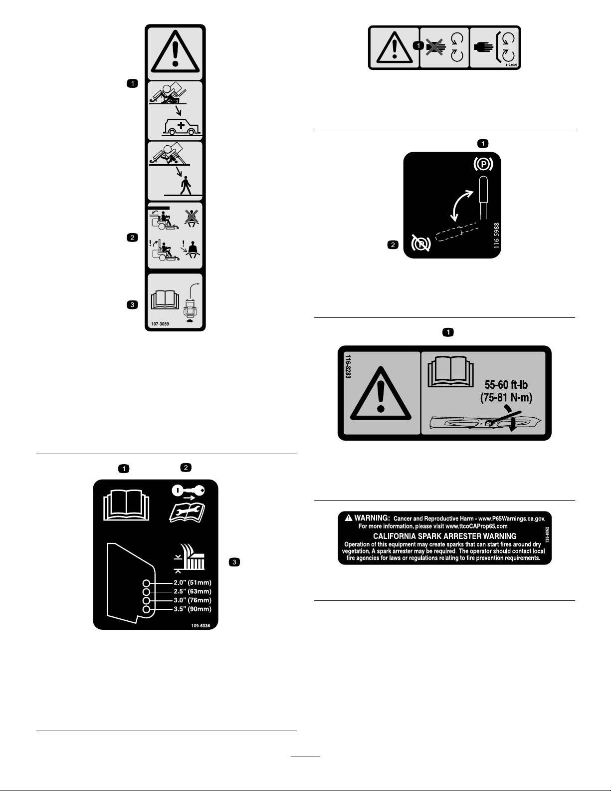
decal107-3069
107-3069
1.Warning—thereisnorolloverprotectionwhentherollbaris
down.
2.Toavoidinjuryordeathfromarolloveraccident,keepthe
rollbarinthefullyraisedandlockedpositionandwear
theseatbelt.Lowertherollbaronlywhenabsolutely
necessary;donotweartheseatbeltwhentherollbaris
down.
3.ReadtheOperator'sManual;driveslowlyandcarefully .
1.Parkingbrake—engaged2.Parking
brake—disengaged
decal116-8283
116-8283
1.Warning—readtheOperator'sManualforinstructionson
torquingthebladebolt/nutto75to81N∙m(55to60ft-lb).
decal133-8062
133-8062
109-6036
RearDischargeMachinesOnly
1.ReadtheOperator’sManual.
2.Removethekeyandreadtheinstructionsbeforeservicing
orperformingmaintenance.
3.Heightofcut
decal109-6036
8
Page 9
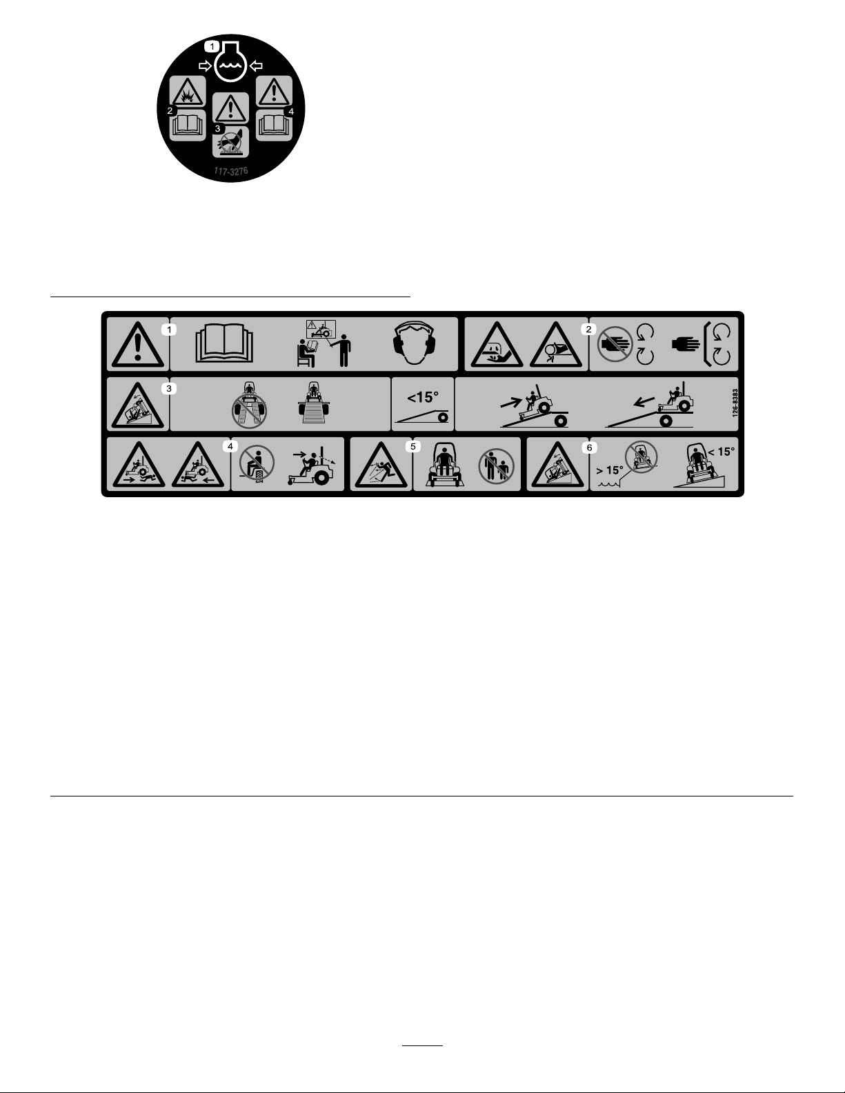
decal117-3276
117-3276
1.Enginecoolantunder
pressure
2.Explosionhazard—read
theOperator'sManual.
3.Warning—donottouchthe
hotsurface.
4.Warning—readthe
Operator'sManual.
126-8383
MachineswithoutMyRideOnly
Note:Thismachinecomplieswiththeindustrystandardstabilitytestinthestaticlateralandlongitudinaltestswiththemaximum
recommendedslopeindicatedonthedecal.ReviewtheinstructionsforoperatingthemachineonslopesintheOperator’sManualas
wellastheconditionsinwhichyouwouldoperatethemachinetodeterminewhetheryoucanoperatethemachineinthoseconditions
onthatdayandatthatsite.Changesintheterraincanresultinachangeinslopeoperationforthemachine.Ifpossible,keepthe
cuttingunitsloweredtothegroundwhileoperatingthemachineonslopes.Raisingthecuttingunitswhileoperatingonslopescan
causethemachinetobecomeunstable.
decal126-8383
1.Warning—readtheOperator’sManual;donotoperatethis
machineunlessyouaretrained;wearhearingprotection.
2.Cutting,dismembering,andentanglementhazard—keep
handsawayfrommovingparts;keepallguardsandshieldsin
place.
3.Ramphazard—whenloadingontoatrailer,donotusedual
ramps;onlyuseasingularrampwideenoughforthemachine
andthathasaninclinelessthan15°;backuptheramp(in
reverse)anddriveforwardofftheramp.
4.Bodilyharmhazard—donotcarrypassengers;lookbehind
youwhenmowinginreverse.
5.Thrownobjecthazard—keepbystandersaway .
6.Tippinghazardonslopes—donotuseonslopesnearopen
water;donotuseonslopesgreaterthan15°.
9
Page 10
126-8597
ForModelswith244cm(96-inch)Decks
decal126-8597
1.Heightofcut
ForModelswith244cm(96-inch)Decks
1.Heightofcut
2.Rangeadjustment
decal126-8760
126-8760
2.Rangeadjustment
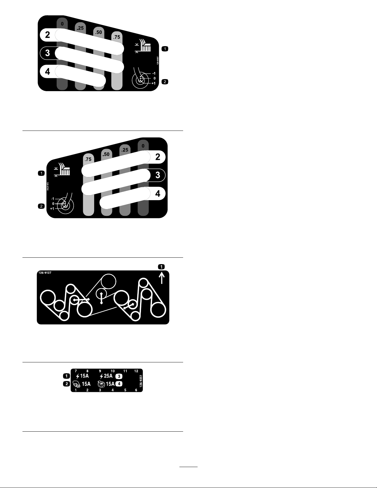
126-9127
ForModelswith244cm(96-inch)Decks
1.Frontofdeck
126-9351
1.Chassis(15A)3.Main(25A)
2.Accessory(15A)4.Powerpoint(15A)
decal126-9127
decal126-9351
10
Page 11
decal126-9947
126-9947
1.ReadandunderstandtheOperator’sManualbeforeservicing
7.Checktheoillevelinthejackshaft.
themachine.
2.Timeinterval
8.GreasethedeckdrivePTO;refertotheOperator’sManual
forfurtherinstructions.
3.Checktheengine-oillevel.9.Checktheaircleaner.
4.Checkthecoolantlevel;refertotheOperator’sManualfor
furtherinstructions.
10.Greasetheidlerpivots(3locations);refertotheOperator’s
Manualforfurtherinstructions.
5.Checkthetirepressure(2locations).11.Greasethefrontcasterwheelbearings(4locations);referto
theOperator’sManualforfurtherinstructions.
6.Checkthehydraulic-uidlevel;refertotheOperator’sManual
forfurtherinstructions.
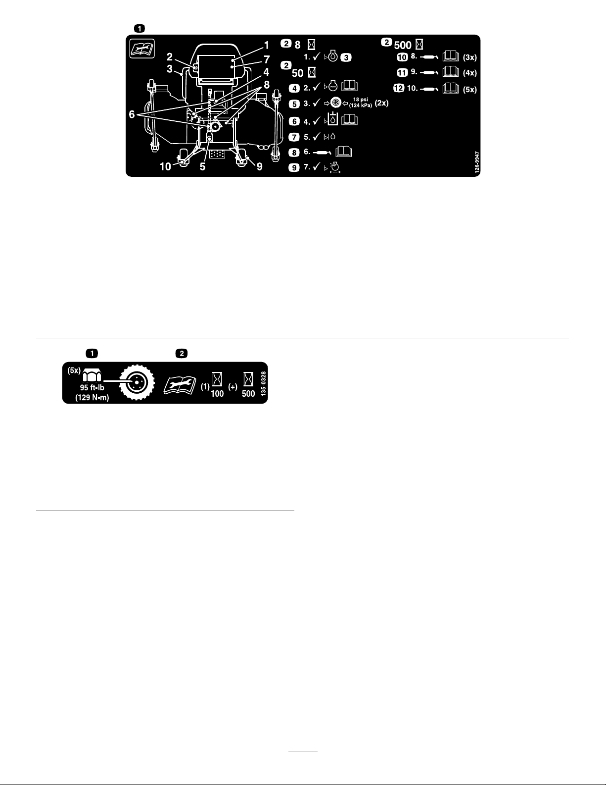
decal135-0328
12.Greasethefrontcasterpivots(5locations);refertothe
Operator’sManualforfurtherinstructions.
135-0328
1.Torquethewheellugnuts
to129N∙m(95ft-lb).
2.Readandunderstand
theOperator'sManual
beforeperformingany
maintenance;checkthe
torqueaftertherst100
hours,thenevery500
hours,thereafter.
11
Page 12
decal135-0398
135-0398
1.Engine—Off4.Pressthetopofthebuttontolowerthecenterdeckandouter
wingdecks.
2.Engine—On5.Pressthebottomofthebuttontoraisethecenterdeckand
outerwingdecks.
3.Engine—Start
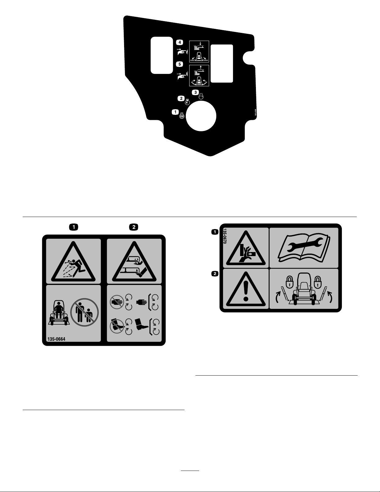
135-0670
ForModelswith244cm(96-inch)Decks
2.Warning—lockthe
deckwingsandread
theinstructionsbefore
servicingorperforming
maintenance.
1.Thrownobjects
hazard—keepbystanders
asafedistanceawayfrom
themachine.
135-0664
RearDischargeMowersOnly
2.Cutting/dismembermentof
decal135-0664
handandfeet—stayaway
frommovingparts;keep
allguardsandshieldsin
place.
1.Crushinghazard,
hand—readthe
instructionsbefore
servicingorperforming
maintenance.
decal135-0670
12
Page 13
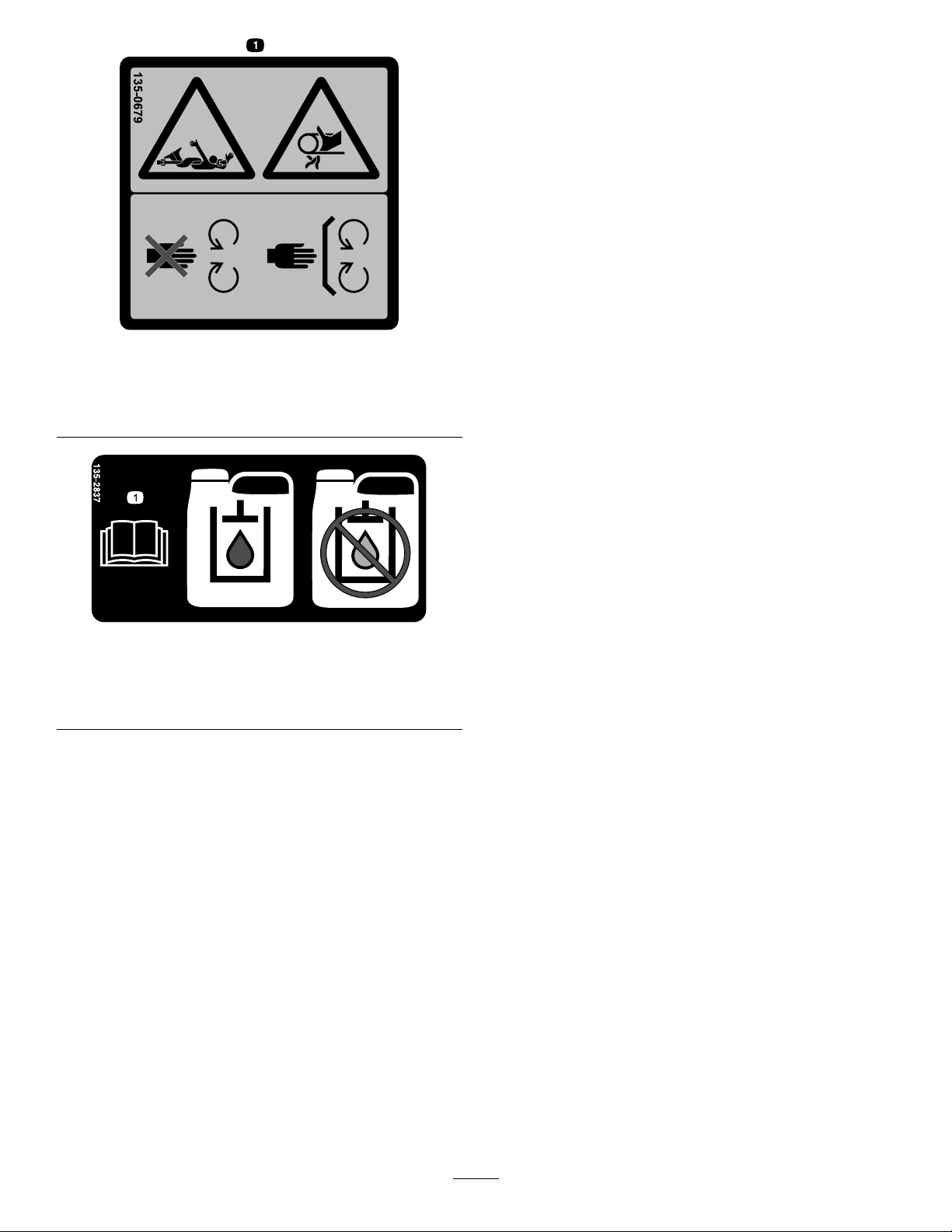
135-0679
1.Rotatingdrivelinehazard/entanglementhazard;belt—stay
awayfrommovingparts;keepallguardsandshieldsin
place.
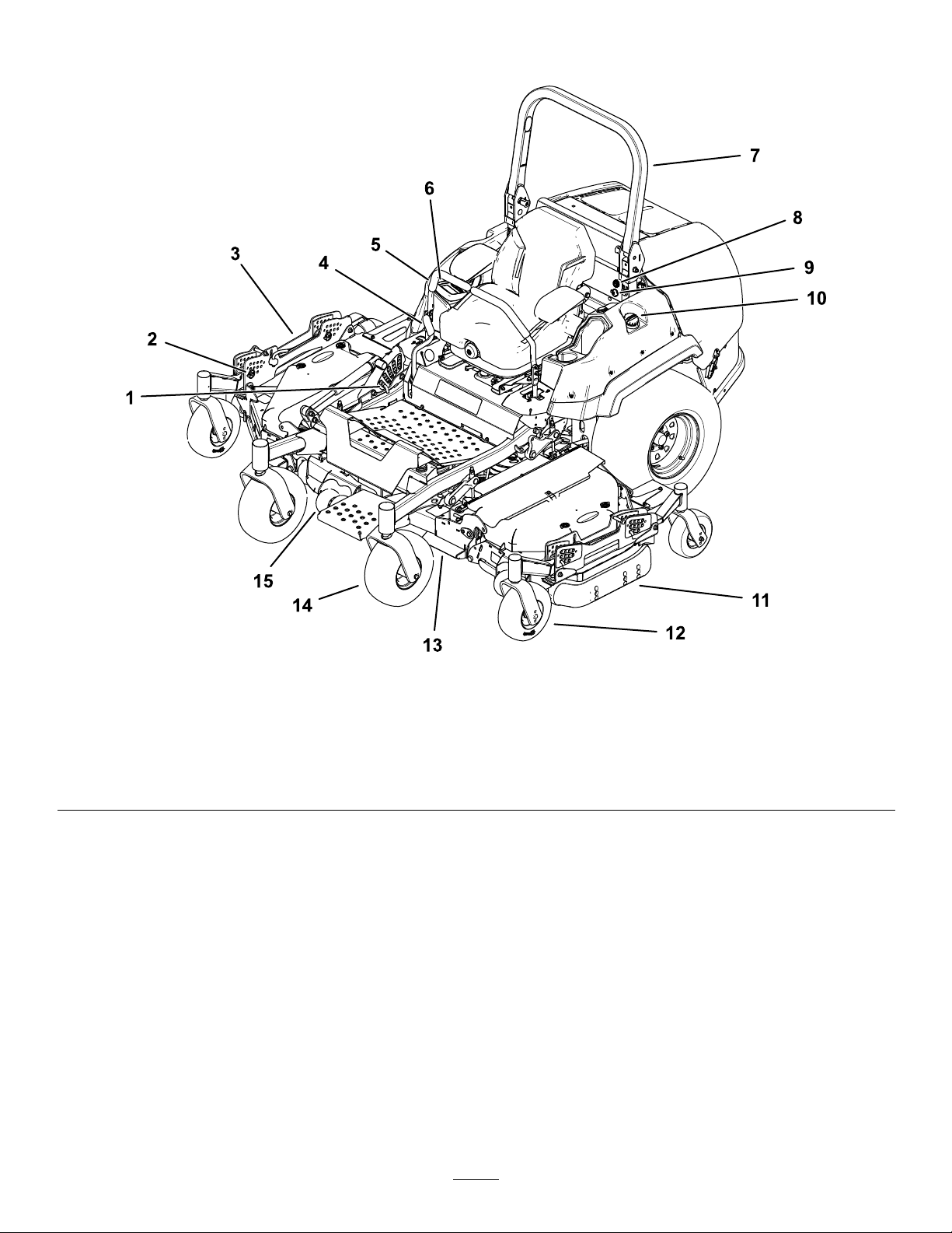
135-2837
1.ReadtheOperator’sManualformoreinformation;Use
redTorowet-clutchtransmissionuid;donotusegreen
hydraulicuid.
decal135-0679
decal135-2837
13
Page 14
ProductOverview
1.Centerdeckheight-of-cut
pin
2.Wingdeckheight-of-cutpin
3.Wingdeck
4.Parking-brakelever
Figure4
5.Motion-controllever9.Powerpoint
6.Displaymonitor10.Fuel-tankcap
7.Rollbar
8.Audiblealarm12.Wingdeckcasterwheel
11.Skid
g236048
13.Centerdeck
14.Centerdeckcasterwheel
15.Anti-scalproller
14
Page 15
Controls
Becomefamiliarwithallthecontrolsbeforeyoustart
theengineandoperatethemachine.
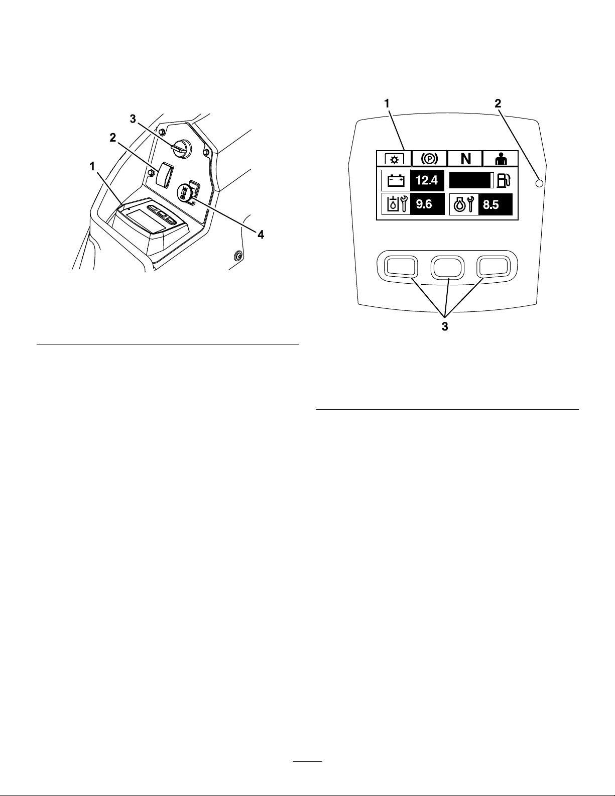
ControlPanel
Figure5
1.Horizondisplaymonitor3.Keyswitch
2.Deckliftandwingdeck
fold/unfoldswitch
4.PTO
HorizonDisplayMonitor
RefertotheSoftwareGuidefordetailedinformation
explainingtheoperatorinterfacethatallowsyouto
accessinformation,resetcounters,modifysystem
settings,andtroubleshoottheequipment.
g225792
g228164
Figure6
HorizonDisplayMonitor
1.Screen
2.LEDstatuslight
InformationScreen
3.Buttons
Theinformationscreendisplaysinformationrelative
tomachineoperation;refertotheSoftwareGuidefor
moreinformation.
Buttons
Themulti-functionalbuttonsarelocatedatthebottom
ofthepanel.Theiconsdisplayedontheinformation
screenabovethebuttonsindicatethecurrentfunction.
Thebuttonsallowyoutoselecttheenginespeedand
navigatethroughsystemmenus.
RefertotheSoftwareGuideformoreinformation.
LEDStatusLight
TheLEDstatuslightismulti-coloredtoindicatethe
systemstatusandislocatedontherightsideofthe
panel.Duringstartup,theLEDilluminatesredto
orangetogreentoverifyfunctionality.
•Solidgreen—indicatesnormaloperatingactivity
•Blinkingred—indicatesanactivefault
•Blinkinggreenandorange—indicatesthata
clutchresetisrequired
RefertotheSoftwareGuideformoreinformation.
15
Page 16

Alarm
Ifanerroroccurs,anerrormessagedisplays,theLED
turnsred,andthealarmsoundsaudiblyasfollows:
•Afastchirpsoundindicatescriticalerrors.
theblades.EngagingthePTOrequiresyoutoreset
thePTOswitchbydisengaging,thenengagingit.
Important:Youmustunfoldthewingdecks
beforeyoucanengagethePTO.
•Aslowchirpingsoundindicateslesscriticalerrors,
suchasrequiredmaintenanceorserviceintervals.
Note:Duringstartup,thealarmsoundsbrieyto
verifyfunctionality.
RefertotheSoftwareGuideformoreinformation.
HourMeter
Thehourmeterrecordsthenumberofhoursthe
enginehasoperated.Itoperateswhentheengine
isrunning.Usethesetimesforschedulingregular
maintenance(Figure5).
HoursaredisplayedinEngine-Offscreenorinthe
EngineHourCountermenu.
RefertotheSoftwareGuideformoreinformation.
ThrottleControl
Thethrottlecontrolstheenginespeed,andthereare
3speeds:Maximum,Efcient,andLow.
RefertotheSoftwareGuideformoreinformation.
DeckLiftandWingDeck
Fold/UnfoldSwitch
Neutral-LockPosition
UsetheNEUTRAL-LOCKpositionwiththe
safety-interlocksystemtoengageandtodetermine
theNEUTRALposition.
KeySwitch
Usethisswitchtostarttheengine.Ithas3positions:
START,RUN,andOFF.
Note:TheLCDindicatorsappearwheneachcontrol
meetsthe“safetostart”mode(e.g.,theindicator
turnsonwhenyouareintheseat.)
Note:TheengineECUcontrolstheglowplugsduring
coldstarts.Ifthecoolanttemperatureistoolow,the
glowsymboldisplaysonthemonitorandthestarter
doesnotcrankwhenyouturntheenginetotheSTART
position.TheglowplugsactivateintheONorSTART
position.Oncetheglowhasbeenonlongenough
forthecurrenttemperature,theglowsymbolonthe
monitordisappearsandtheenginecrankswhen
turnedtotheST ARTposition.
Note:Thesystemallowsyoutostartthemachinethe
withthePTOswitchengaged,butdoesnotengage
theblades.Y oumustresetthePTOtoengagethe
PTO.
Presstheswitchrearwardtoraisethecenterdeck
andtofoldthewingdecks.
Presstheswitchforwardtolowerthecenterdeckand
tounfoldthewingdecks.
Blade-ControlSwitch(Power
Takeoff)
Theblade-controlswitch(PTO)engagesand
disengagespowertothemowerblades(Figure5).
TheLCDindicatorappearsontheinformationscreen
whenthePTOswitchisdisengaged.
Note:MachinesequippedwiththeHorizonDisplay
Monitorhaveaclutchsaver,whichallowsthethrottle
toautomaticallyreducetheenginespeedwhen
youdisengagethePTOswitch.Engagingand
disengagingthePTOswitchchangestheengine
throttlebetweenMOWandTRANSPORTmode.
Note:Thesystemallowsyoutostartthemachine
withthePTOswitchengaged,butdoesnotengage
Attachments/Accessories
AselectionofT oroapprovedattachmentsand
accessoriesisavailableforusewiththemachine
toenhanceandexpanditscapabilities.Contact
yourAuthorizedServiceDealerorauthorizedT oro
distributororgotowww.Toro.comforalistofall
approvedattachmentsandaccessories.
Toensureoptimumperformanceandcontinuedsafety
certicationofthemachine,useonlygenuineT oro
replacementpartsandaccessories.Replacement
partsandaccessoriesmadebyothermanufacturers
couldbedangerous,andsuchusecouldvoidthe
productwarranty.
16
Page 17

Specications
Cuttingwidth243.8cm(96inches)
Workingwidth—257.3cm
(101-5/16inches)
Overallwidth
Overalllength247.1cm(97-1/4inches)
Overallheight
Treadwidth(center-to-center
oftires,widthwise)
Wheelbase(centerofthe
castertiretothecenterofthe
drivetire)
Overallweight1172kg(2,584lb)
Transportwidthsetatthe
3-inchesheightofcut—184.2
cm(72-1/2inches)
Rollbarup—182.4cm
(71-13/16inches)
Rollbardown—129.5cm(51
inches)
Drivewheels—1 17cm
(46-1/16inches)
Casterwheels—120.7cm
(47-1/2inches)
143cm(56-5/16inches)
Operation
Note:Determinetheleftandrightsidesofthe
machinefromthenormaloperatingposition.
BeforeOperation
BeforeOperationSafety
GeneralSafety
•Neverallowchildrenoruntrainedpeopleto
operateorservicethemachine.Localregulations
mayrestricttheageoftheoperator.Theowner
isresponsiblefortrainingalloperatorsand
mechanics.
•Becomefamiliarwiththesafeoperationofthe
equipment,operatorcontrols,andsafetysigns.
•Knowhowtostopthemachineandshutoffthe
enginequickly.
•Checkthatoperator-presencecontrols,safety
switches,andshieldsareattachedandfunctioning
properly.Donotoperatethemachineunlessthey
arefunctioningproperly.
•Beforemowing,alwaysinspectthemachineto
ensurethattheblades,bladebolts,andcutting
assembliesareingoodworkingcondition.
Replacewornordamagedbladesandboltsinsets
topreservebalance.
•Inspecttheareawhereyouwillusethemachine
andremoveallobjectsthatthemachinecould
throw.
•Evaluatetheterraintodeterminetheappropriate
equipmentandanyattachmentsoraccessories
requiredtooperatethemachineproperlyand
safely.
FuelSafety
•Toavoidpersonalinjuryorpropertydamage,use
extremecareinhandlingfuel.Fuelvaporsare
ammableandexplosive.
•Extinguishallcigarettes,cigars,pipes,andother
sourcesofignition.
•Useonlyanapprovedfuelcontainer.
•Donotremovethefuelcaporaddfueltothefuel
tankwhiletheengineisrunningorwhilehot.
•Donotrefuelthemachineindoors.
•Donotstorethemachineorfuelcontainerwhere
thereisanopename,spark,orpilotlight,such
asonawaterheateroronotherappliances.
•Donotllcontainersinsideavehicleoronatruck
ortrailerbedwithaplasticliner.Alwaysplace
17
Page 18

containersontheground,awayfromyourvehicle
beforelling.
•Removetheequipmentfromthetruckortrailer
andrefuelitwhileitisontheground.Ifthisisnot
possible,thenrefuelfromaportablecontainer
ratherthanafuel-dispensernozzle.
•Donotoperatethemachinewithouttheentire
exhaustsysteminplaceandinproperworking
condition.
•Keepthefuel-dispensernozzleincontactwith
therimofthefueltankorcontaineropeningat
alltimesuntilfuelingiscomplete.Donotusea
nozzlelock-opendevice.
•Ifyouspillfuelonyourclothing,changeyour
clothingimmediately.Wipeupanyfuelthatspills.
•Neveroverllthefueltank.Replacethefuelcap
andtightenitsecurely.
•Storefuelinanapprovedcontainerandkeepit
outofthereachofchildren.Neverbuymorethan
a30-daysupplyoffuel.
•Donotllthefueltankcompletelyfull.Addfuelto
thefueltankuntilthelevelis6to13mm(1/4to
1/2inch)belowthebottomofthellerneck.This
emptyspaceinthetankallowsfueltoexpand.
–Avoidprolongedbreathingofvapors.
–Keepyourfaceawayfromthenozzleandfuel
tankopening.
–Avoidcontactwithskin;washoffspillswith
soapandwater.
BiodieselReady
Thismachinecanalsouseabiodieselblendedfuel
ofuptoB20(20%biodiesel,80%petrodiesel).The
petrodieselportionshouldbeloworultralowsulfur.
Observethefollowingprecautions:
•Thebiodieselportionofthefuelmeetspecication
ASTMD6751orEN14214.
•TheblendedfuelcompositionshouldmeetASTM
D975orEN590.
•Paintedsurfacesmaybedamagedbybiodiesel
blends.
•UseB5(biodieselcontentof5%)orlesserblend
incoldweather.
•Monitorseals,hoses,gasketsincontactwithfuel
astheymaydegradeovertime.
•Fuellterpluggingmaybeexpectedforatime
afterconvertingtobiodieselblends.
•Contactyourdistributorformoreinformationon
biodiesel.
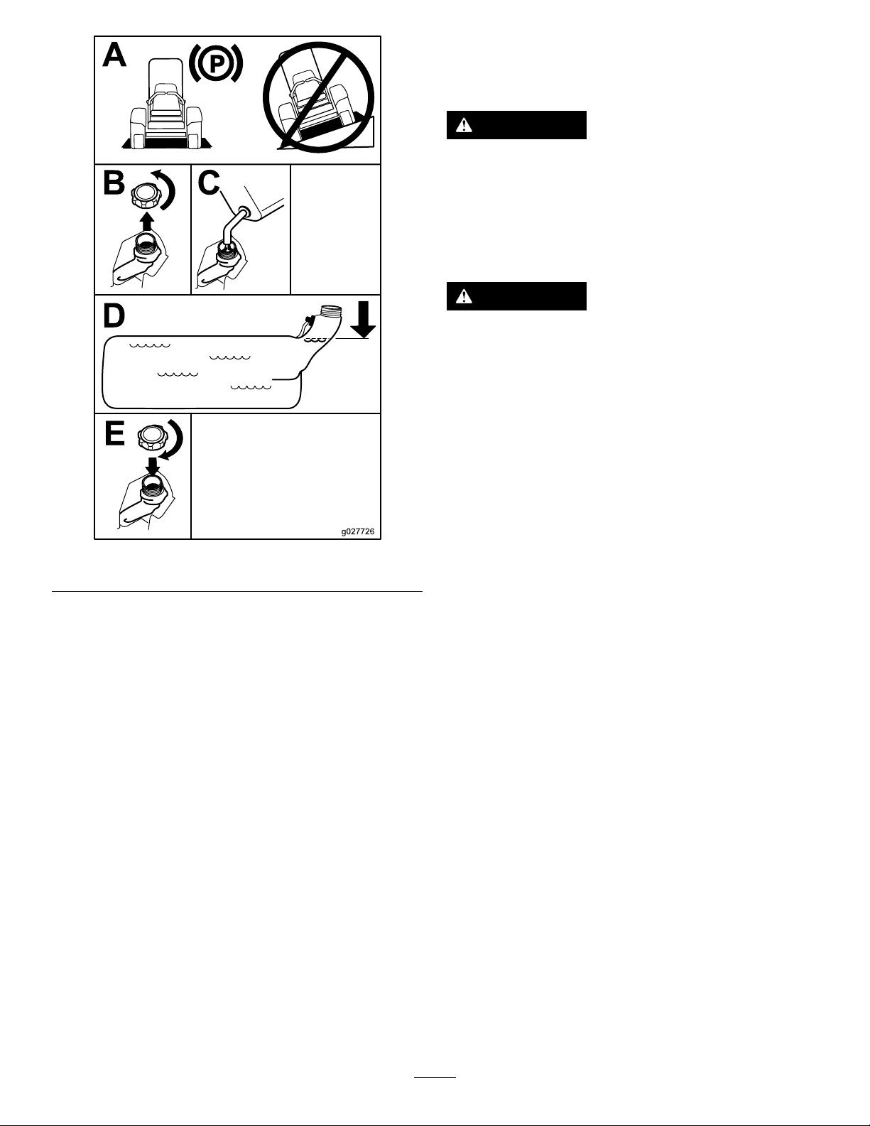
FillingtheFuelTank
1.Parkthemachineonalevelsurface.
2.Engagetheparkingbrake.
3.Shutofftheengineandremovethekey.
4.Cleanaroundthefuel-tankcap.
AddingFuel
RecommendedFuel
Theenginerunsonclean,freshdieselfuelwith
aminimumcetaneratingof40.Purchasefuelin
quantitiesthatcanbeusedwithin30daystoensure
fuelfreshness.
Usesummer-gradedieselfuel(No.2-D)at
temperaturesabove-7°C(20°F)andwinter-grade
dieselfuel(No.1-DorNo.1-D/2-Dblend)below
-7°C(20°F).Useofwinter-gradedieselfuelatlower
temperaturesprovideslowerashpointandpour
pointcharacteristics,thereforeeasingstartabilityand
lesseningchancesofchemicalseparationofthefuel
duetolowertemperatures(waxappearance,which
maypluglters).
Usingsummer-gradedieselfuelabove-7°C
(20°F)contributestowardlongerlifeofthepump
components.
Important:Donotusekeroseneorgasoline
insteadofdieselfuel.Failuretoobservethis
cautionwilldamagetheengine.
5.Fillthefueltanktothebottomofthellerneck
(Figure7).
Note:Donotllthefueltankcompletelyfull.
Theemptyspaceinthetankallowsthefuelto
expand.
18
Page 19
UsingtheRollover ProtectionSystem(ROPS)
WARNING
Toavoidinjuryordeathfromrollover:keep
therollbarintheraisedlockedpositionand
usetheseatbelt.
Ensurethattherearpartoftheseatissecured
withtheseatlatch.
WARNING
Thereisnorolloverprotectionwhentheroll
barisinthedownposition.
•Lowertherollbaronlywhenabsolutely
necessary.
•Donotweartheseatbeltwhentherollbar
isinthedownposition.
•Driveslowlyandcarefully.
Figure7
PerformingDaily Maintenance
Beforestartingthemachineeachday ,performthe
EachUse/DailyprocedureslistedinMaintenance
(page35).
BreakinginaNewMachine
Newenginestaketimetodevelopfullpower.Mower
decksanddrivesystemshavehigherfrictionwhen
new,placingadditionalloadontheengine.Allow
40to50hoursofbreak-intimefornewmachinesto
developfullpowerandbestperformance.
•Raisetherollbarassoonasclearance
permits.
g027726
•Checkcarefullyforoverheadclearances
(i.e.,branches,doorways,electricalwires)
beforedrivingunderanyobjectsanddo
notcontactthem.
Important:Lowertherollbaronlywhen
absolutelynecessary.
1.Ensurethattheknobiscompletelylatchedwith
thetabsinterlockingasshowninFigure8tolock
therollbarintheraisedposition.
2.Tolowertherollbar,applyforwardpressureto
theupperpartoftherollbar.
3.Pullbothknobsoutandrotatethem90°sothey
arenotengaged(Figure8).
4.Toraisetherollbar,raisetherollbartothe
operateposition,rotatetheknobssothatthey
movepartiallyintothegrooves(Figure8).
5.Raisetherollbartothefulluprightpositionwhile
pushingontheupperrollbarandthepinssnap
intopositionwhentheholesalignwiththepins
(Figure8).
Important:Alwaysusetheseatbeltwiththe
rollbarintheraisedposition.
19
Page 20
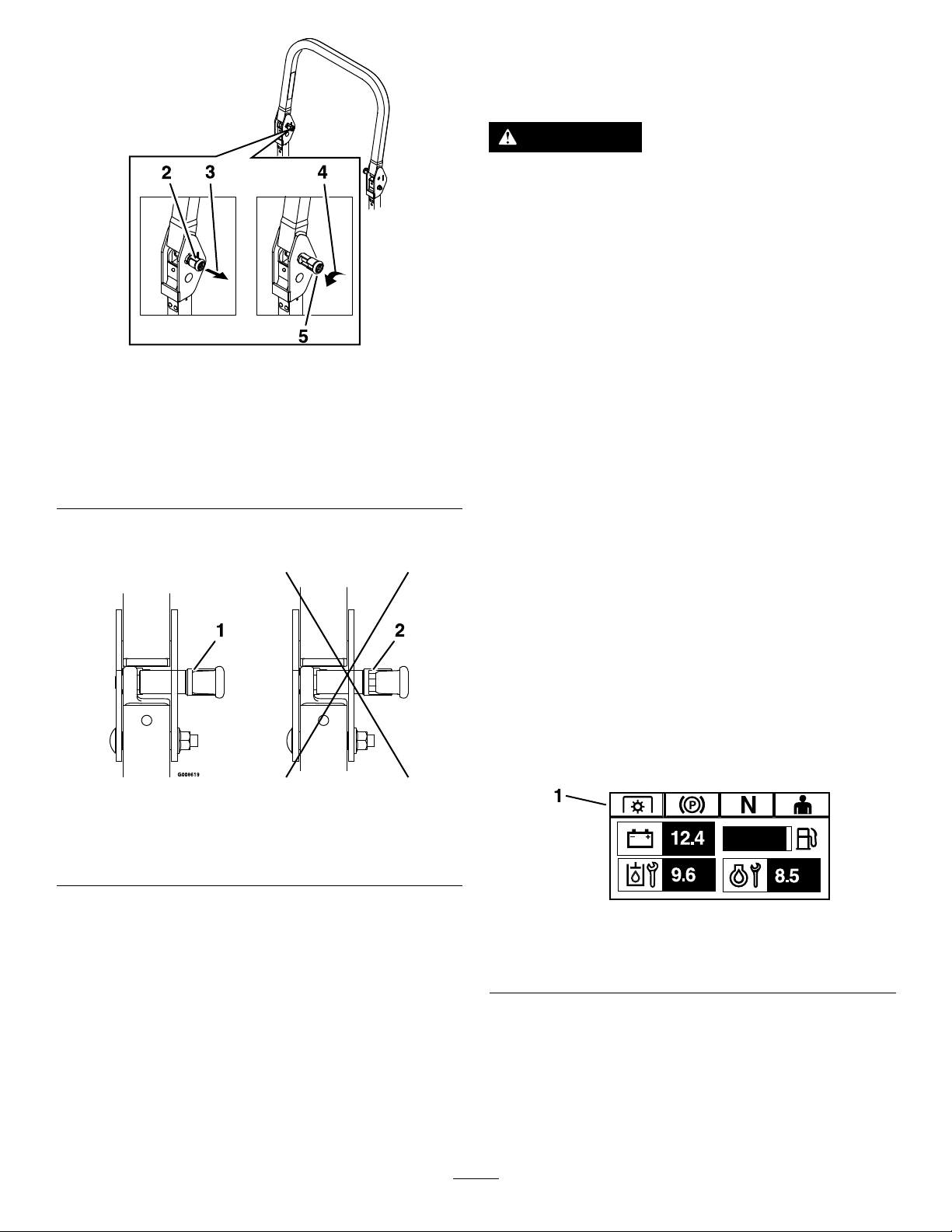
Figure8
1.Upperpartoftherollbar4.Rotatetheknobout90°
2.Knobinthelatched
position
3.Pulltheknobtounlatch.
toholditintheunlatched
position.
5.Knobintheunlatched
position
UsingtheSafety-Interlock System
WARNING
Ifthesafety-interlockswitchesare
disconnectedordamaged,themachinecould
operateunexpectedly,causingpersonal
injury.
•Donottamperwiththeinterlockswitches.
•Checktheoperationoftheinterlock
switchesdailyandreplaceanydamaged
switchesbeforeoperatingthemachine.
g225804
Understandingthe Safety-InterlockSystem
Thesafety-interlocksystemisdesignedtopreventthe
enginefromstartingunless:
•Theparkingbrakeisengaged.
6.Pushontherollbarandensurethatbothpins
areengaged(Figure9).
Figure9
1.Engaged2.Partiallyengaged—donot
operatethemachinewith
theROPSinthisposition.
•Theblade-controlswitch(PTO)isdisengaged.
•Themotion-controlleversareintheNEUTRAL-LOCK
position.
Thesafety-interlocksystemalsoisdesignedtoshut
offtheenginewhenthemotion-controlleversare
movedfromtheNEUTRAL-LOCKpositionwiththe
parkingbrakeengagedorifyourisefromtheseat
whenthePTOisengaged.
TheHorizonDisplayMonitorhassymbolstonotify
theuserwhentheinterlockcomponentisinthe
correctposition.Whenthecomponentisinthecorrect
position,thecorrespondingsymboldisplaysonthe
g008619
monitor.
g230650
Figure10
1.Symbolsdisplayonthemonitorwhentheinterlock
componentsareinthecorrectposition.
20
Page 21
TestingtheSafety-Interlock System
ServiceInterval:Beforeeachuseordaily
Testthesafety-interlocksystembeforeyouusethe
machineeachtime.Ifthesafetysystemdoesnot
operateasdescribedbelow,haveanAuthorized
ServiceDealerrepairthesafetysystemimmediately .
1.Sitontheseat,engagetheparkingbrake,and
movetheblade-controlswitch(PTO)totheON
position.Trystartingtheengine;theengine
shouldnotstart.
2.Sitontheseat,engagetheparkingbrake,and
movetheblade-controlswitch(PTO)totheOFF
position.Moveeithermotion-controlleverout
oftheNEUTRAL-LOCKposition.Trystartingthe
engine;theengineshouldnotstart.Repeatfor
theothercontrollever.
3.Sitontheseat,engagetheparkingbrake,
movetheblade-controlswitch(PTO)totheOFF
position,andmovethemotion-controllevers
totheNEUTRAL-LOCKposition.Nowstartthe
engine.Whiletheengineisrunning,disengage
theparkingbrake,engagetheblade-control
switch(PTO),andriseslightlyfromtheseat;the
engineshouldshutoff.
4.Sitontheseat,engagetheparkingbrake,
movetheblade-controlswitch(PTO)totheOFF
position,andmovethemotion-controllevers
totheNEUTRAL-LOCKposition.Nowstartthe
engine.Whiletheengineisrunning,center
eithermotioncontrolandmove(forwardor
reverse);theengineshouldshutoff.Repeatfor
othermotioncontrol.
5.Sitontheseat,disengagetheparkingbrake,
movetheblade-controlswitch(PTO)totheOFF
position,andmovethemotion-controllevers
totheNEUTRAL-LOCKposition.Trystartingthe
engine;theengineshouldnotstart.
g019754
Figure11
UnlatchingtheSeat
g019755
Figure12
1.Seatlatch2.Seat
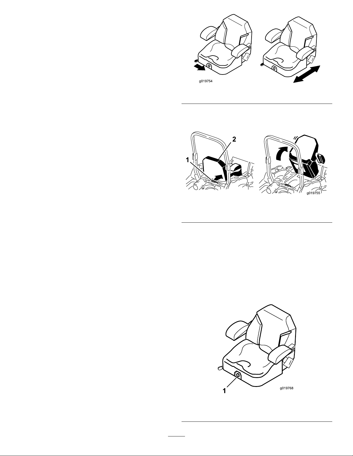
ChangingtheSeat Suspension
Theseatisadjustabletoprovideasmoothand
comfortableride.Positiontheseatwhereyouare
mostcomfortable.
Toadjustit,turntheknobinfronteitherdirectionto
providethebestcomfort(Figure13).
PositioningtheSeat
Theseatmovesforwardandbackward.Positionthe
seatwhereyouhavethebestcontrolofthemachine
andaremostcomfortable.
Toadjust,movetheleversidewaystounlocktheseat
(Figure11).
g019768
Figure13
1.Seat-suspensionknob
21
Page 22

DuringOperation
DuringOperationSafety
GeneralSafety
•Theowner/operatorcanpreventandisresponsible
foraccidentsthatmaycausepersonalinjuryor
propertydamage.
•Wearappropriateclothing,includingeye
protection;longpants;slip-resistant,substantial
footwear;andhearingprotection.Tiebacklong
hairanddonotwearloosejewelry .
•Useyourfullattentionwhileoperatingthe
machine.Donotengageinanyactivitythat
causesdistractions;otherwise,injuryorproperty
damagemayoccur.
•Donotoperatethemachinewhileill,tired,or
undertheinuenceofalcoholordrugs.
•Nevercarrypassengersonthemachineandkeep
bystandersandpetsawayfromthemachine
duringoperation.
•Operatethemachineonlyingoodvisibilitytoavoid
holesorhiddenhazards.
•Avoidmowingonwetgrass.Reducedtraction
couldcausethemachinetoslide.
•Ensurethatalldrivesareinneutral,theparking
brakeisengaged,andyouareintheoperating
positionbeforeyoustarttheengine.
•Keepyourhandsandfeetawayfromthecutting
units.Keepclearofthedischargeopeningatall
times.
•Lookbehindanddownbeforebackinguptobe
sureofaclearpath.
•Usecarewhenapproachingblindcorners,shrubs,
trees,orotherobjectsthatmayobscureyour
vision.
•Donotmowneardrop-offs,ditches,or
embankments.Themachinecouldsuddenlyroll
overifawheelgoesovertheedgeoriftheedge
givesway.
•Stopthebladeswheneveryouarenotmowing.
•Stopthemachine,shutofftheengine,remove
thekey,andinspectthebladesafterstrikingan
objectorifthereisanabnormalvibrationinthe
machine.Makeallnecessaryrepairsbefore
resumingoperation.
•Slowdownandusecautionwhenmakingturns
andcrossingroadsandsidewalkswiththe
machine.Alwaysyieldtheright-of-way.
•Disengagethedrivetothecuttingunit,shutoffthe
engine,andremovethekeybeforeadjustingthe
heightofcut(unlessyoucanadjustitfromthe
operatingposition).
•Neverrunanengineinanareawhereexhaust
gasesareenclosed.
•Neverleavearunningmachineunattended.
•Beforeleavingtheoperatingposition(including
toemptythecatchersortounclogthechute),do
thefollowing:
–Stopthemachineonlevelground.
–Disengagethepowertakeoffandlowerthe
attachments.
–Engagetheparkingbrake.
–Shutofftheengineandremovethekey.
–Waitforallmovingpartstostop.
•Donotoperatethemachinewhenthereistherisk
oflightning.
•Donotusethemachineasatowingvehicleunless
ithasahitchinstalled.
•Donotchangethegovernorspeedoroverspeed
theengine.
•Useonlyaccessoriesandattachmentsapproved
byToro.
•Thismachineproducessoundlevelsinexcess
of85dBAattheoperator’searandcancause
hearinglossthroughextendedperiodsof
exposure.
g229846
Figure14
1.Wearhearingprotection.
RolloverProtectionSystem (ROPS)Safety
•Donotremovetherollbarfromthemachine.
•Ensurethattheseatbeltisattachedandthatyou
canreleaseitquicklyinanemergency.
•Alwayswearyourseatbeltwhentherollbarisup.
•Checkcarefullyforoverheadobstructionsanddo
notcontactthem.
•Keeptherollbarinsafeoperatingconditionby
thoroughlyinspectingitperiodicallyfordamage
andkeepingallthemountingfastenerstight.
•Replaceadamagedrollbar.Donotrepairoralter
it.
SlopeSafety
•Slopesareamajorfactorrelatedtolossofcontrol
androlloveraccidents,whichcanresultinsevere
22
Page 23

injuryordeath.Theoperatorisresponsiblefor
safeslopeoperation.Operatingthemachineon
anysloperequiresextracaution.Beforeusingthe
machineonaslope,dothefollowing:
–Reviewandunderstandtheslopeinstructions
inthemanualandonthemachine.
–Useanangleindicatortodeterminethe
approximateslopeangleofthearea.
–Neveroperateonslopesgreaterthan15
degrees.
–Evaluatethesiteconditionsofthedayto
determineiftheslopeissafeformachine
operation.Usecommonsenseandgood
judgmentwhenperformingthisevaluation.
Changesintheterrain,suchasmoisture,can
quicklyaffecttheoperationofthemachineon
aslope.
•Identifyhazardsatthebaseoftheslope.Do
notoperatethemachineneardrop-offs,ditches,
embankments,water,orotherhazards.The
machinecouldsuddenlyrolloverifawheelgoes
overtheedgeortheedgecollapses.Keepasafe
distance(twicethewidthofthemachine)between
themachineandanyhazard.Useawalk-behind
machineorahandtrimmertomowthegrassin
theseareas.
1.SafeZone—usethe
machinehereonslopes
lessthan15degreesor
atareas.
2.DangerZone—usea
walk-behindmowerand/or
ahandtrimmeronslopes
greaterthan15degrees
andneardrop-offsor
water.
3.Water
g221745
Figure15
4.W=widthofthemachine
5.Keepasafedistance
(twicethewidthofthe
machine)betweenthe
machineandanyhazard.
•Avoidstarting,stopping,orturningthemachineon
slopes.Avoidmakingsuddenchangesinspeedor
direction;turnslowlyandgradually.
•Donotoperateamachineunderanyconditions
wheretraction,steering,orstabilityisinquestion.
Beawarethatoperatingthemachineonwet
grass,acrossslopes,ordownhillmaycausethe
machinetolosetraction.Lossoftractiontothe
drivewheelsmayresultinslidingandalossof
brakingandsteering.Themachinecanslideeven
ifthedrivewheelsarestopped.
•Removeormarkobstaclessuchasditches,holes,
ruts,bumps,rocks,orotherhiddenhazards.T all
grasscanhideobstacles.Uneventerraincould
overturnthemachine.
•Useextracarewhileoperatingwithaccessoriesor
attachments,suchasgrass-collectionsystems.
Thesecanchangethestabilityofthemachine
andcausealossofcontrol.Followdirectionsfor
counterweights.
•Ifpossible,keepthedeckloweredtotheground
whileoperatingonslopes.Raisingthedeckwhile
operatingonslopescancausethemachineto
becomeunstable.
23
Page 24

OperatingtheParking
LoweringtheWingDecks
Brake
Alwaysengagetheparkingbrakewhenyoustopthe
machineorleaveitunattended.
EngagingtheParkingBrake
Parkthemachineonalevelsurface.
Figure16
Important:Youmustunfoldthewingdecks
beforeyoucanengagethePTO.
1.Removetheclevispinandhairpincotterthat
secureseachwingintheuprightpositionand
placetheminthestorageposition(Figure18).
g227611
DisengagingtheParkingBrake
Figure17
g212197
Figure18
1.Pinstoragelocation
2.Ensurethatallpersonsareclearofthedeck
wings.
3.Pressandholdthebottomofthedeck-liftswitch;
thecenterdecklowersrst,thentheouterwings.
g227610
24
Page 25

OperatingtheMower Blade-ControlSwitch(PTO)
Theblade-controlswitch(PTO)startsandstopsthe
mowerbladesandanypoweredattachments.
EngagingtheBlade-Control Switch(PTO)
Note:Engagingtheblade-controlswitch(PTO)with
thethrottlepositionathalforlesscausesexcessive
weartothedrivebelts.
Figure19
g008945
DisengagingtheBlade-Control Switch(PTO)
g009174
Figure20
StartingtheEngine
Important:Donotengagestarterformorethan5
secondsatatime.Iftheenginefailstostart,wait
15secondsbetweenattempts.Failuretofollow
theseinstructionscanburnoutthestartermotor.
Note:Youmayneedmultipleattemptstostartthe
enginethersttimeafteraddingfueltoanemptyfuel
system.
g230704
Figure21
25
Page 26

ShuttingOfftheEngine
CAUTION
Childrenorbystandersmaybeinjuredifthey
moveorattempttooperatethemachinewhile
itisunattended.
Alwaysremovethekeyandengagethe
parkingbrakewhenleavingthemachine
unattended.
RaisingandLockingthe WingDecks
1.Ensurethatallpersonsareclearofthedeck
wings.
2.Pressandholdthebottomofthedeck-liftswitch;
thecenterdecklowersrst,thentheouterwings.
3.Parkthemachineonalevelsurface,disengage
theblade-controlswitch,andengagetheparking
brake.
4.Shutofftheengine,removethekey ,andwait
forallmovingpartstostopbeforeleavingthe
operatingposition.
5.Removetheclevispinandhairpincotterfrom
thestoragelocationandsecureeachwinginthe
uprightposition(Figure23).
Figure22
g230715
g212236
Figure23
1.Clevispin
26
2.Hairpincotter
Page 27

UsingtheMotion-Control
DrivingtheMachine
Levers
Thedrivewheelsturnindependently,poweredby
hydraulicmotorsoneachaxle.Youcanturn1side
inreversewhileyouturntheotherforward,causing
themachinetospinratherthanturn.Thisgreatly
improvesthemachinemaneuverabilitybutmay
requiresometimeforyoutoadapttohowitmoves.
Thethrottlecontrolregulatestheenginespeedas
measuredinrpm(revolutionsperminute).Place
thethrottlecontrolintheFASTpositionforbest
performance.Alwaysoperateinthefullthrottle
positionwhenmowing.
WARNING
Themachinecanspinveryrapidly.Y ou
maylosecontrolofthemachineandcause
personalinjuryordamagetothemachine.
•Usecautionwhenmakingturns.
•Slowthemachinedownbeforemaking
sharpturns.
DrivingForward
Figure24
1.Motion-control
lever—NEUTRAL-LOCK
position
2.Center,unlockedposition5.Frontofmachine
3.Forward
4.Backward
Note:Theengineshutsoffwhenyoumovethe
g004532
traction-controlwiththeparkingbrakeengaged.
Tostopthemachine,pullthemotion-controllevers
totheNEUTRALposition.
1.Disengagetheparkingbrake;referto
DisengagingtheParkingBrake(page24).
2.Movetheleverstothecenter,unlockedposition.
3.Togoforward,slowlypushthemotion-control
leversforward(Figure25).
27
Page 28

Figure25
DrivingBackward
1.Movetheleverstothecenter,unlockedposition.
2.Togobackward,slowlypullthemotion-control
leversrearward(Figure26).
g008952
Figure26
g008953
28
Page 29

AdjustingtheHeightofCut
Thecuttingheightofthemowerdeckcanbeadjusted
from2.54cmto14cm(1to5-1/2inches)in6.4mm
(1/4inch)increments.
1.Parkthemachineonalevelsurface,disengage
theblade-controlswitch,andengagetheparking
brake.
2.Pressthetopofdeck-liftswitchtoraisethe
centerdeckandwingdecks.
3.Shutofftheengine,removethekey ,andwait
forallmovingpartstostopbeforeleavingthe
operatingposition.
4.Adjustthecenterdeckbyperformingthe
followingprocedure:
A.Removetheheight-of-cutpinfromthe
deck-liftplateontherightsideofthecenter
deck.
B.Inserttheheight-of-cutpinintothehole
correspondingtothedesiredcuttingheight.
Seethedecalonthesideofthedeck-lift
plateforthecuttingheights.
E.Lockthecamlock.
F.Repeatfortheotherwingdeck.
6.Ifyoudesireadditionalheight-of-cutrange,
adjustthefrontandreargaugewheelsonthe
wingdeckasfollows:
A.Removethemountinghardwarefromthe
gaugewheel.
B.Adjustthefrontandreargaugewheels
totheappropriateholelocation(seethe
chartbelowandFigure28)andinstallthe
mountinghardware.
HoleLocation
Tophole(-1onthedecal)25to89mm(1to3-1/2inches)
Middlehole(0onthedecal)51to1 14mm(2to4-1/2
Bottomhole(+1onthedecal)76to140mm(3to5-1/2
Height-of-CutRange
inches)
inches)
5.Adjustthesidewingdecksbyperformingthe
followingprocedure:
A.Ensurethatthewingdecksarelockedin
place.
B.Unlockthecamlockslocatedonthe
height-of-cutchannelonthewingdeck
(Figure27).
Figure27
1.Camlock
2.Height-of-cutpin
3.Lynchpin
g212253
Figure28
Height-of-cutrange
g239055
1.Tophole(-1onthedecal)
2.Middlehole(0onthedecal)
3.Bottomhole(+1onthedecal)
C.Removethelynchpinfromtheheight-of-cut
pinonboththefrontandrearchannels.
D.Movethewingdecktotheappropriate
heightandinstalltheheight-of-cutpinsand
lynchpins(Figure27).
C.Repeatfortheotherwingdeck.
29
Page 30

AdjustingtheAnti-Scalp Rollers
Formaximumdeckotation,installtherollers1hole
positionlower.Rollersshouldmaintaina6mm(1/4
inch)clearancetotheground.Donotadjustthe
rollerstosupportthedeck.
1.Parkthemachineonalevelsurface.
2.Disengagetheblade-controlswitch(PTO),move
themotion-controlleverstotheNEUTRAL-LOCK
position,andengagetheparkingbrake.
3.Shutofftheengine,removethekey ,andwait
forallmovingpartstostopbeforeleavingthe
operatingposition.
4.Afteradjustingtheheightofcut,adjustthe
anti-scalprollersbyremovingthemounting
hardware.
5.Placetherollersin1ofthepositionsshownin
Figure29.
Therollerswillmaintain19mm(3/4inch)
clearancetothegroundtominimizegouging
androllerwearordamage.
g018862
Figure30
1.Nylocnut(3/8inch)3.Spacer
2.Anti-scalprollers4.Bolt
The96-inchdeckhas13anti-scalprollerlocations.
Foradjustment,refertoFigure31.
Figure29
Forcuttingheightsabove90mm(3-1/5inches),usethe
bottomhole.Therollersarestilleffectiveagainstscalping.
1.Anti-scalprollermounting
bracket
2.Cuttingheight
6.T orquethenylocnut(3/8inch)to41to47N∙m
(30to35ft-lb)asshowninFigure30.
g243016
g238020
Figure31
Undersideofthemowerdeck
1.Anti-scalproller
30
Page 31

AdjustingtheSkids
OperatingTips
ForModelswithRearDischarge
Mounttheskidsinthelowerpositionwhenoperating
atheightsofcutgreaterthan51mm(2inches)and
inahigherpositionwhenoperatingatheightsofcut
lowerthan51mm(2inches).
AdjusttheskidsasshowninFigure32.
Figure32
UsingtheFastThrottleSetting
Forbestmowingandmaximumaircirculation,operate
theengineattheFASTposition.Airisrequiredto
thoroughlycutgrassclippings,sodonotsetthe
height-of-cutsolowastototallysurroundthemower
deckinuncutgrass.Alwaystrytohave1sideofthe
mowerdeckfreefromuncutgrass,whichallowsair
tobedrawnintothemowerdeck.
CuttingaLawnfortheFirstTime
Cutgrassslightlylongerthannormaltoensurethat
thecuttingheightofthemowerdeckdoesnotscalp
anyunevenground.However,thecuttingheight
usedinthepastisgenerallythebestonetouse.
Whencuttinggrasslongerthan15cm(6inches)tall,
youmaywanttocutthelawntwicetoensurean
acceptablequalityofcut.
CuttingaThirdoftheGrassBlade
Itisbesttocutonlyaboutathirdofthegrassblade.
Cuttingmorethanthatisnotrecommendedunless
g035646
grassissparse,oritislatefallwhengrassgrows
moreslowly.
OperatingwiththeOverheat Sensor
ThePTOdisengages,analarmsounds,anda
bargraphdisplaystheenginetemperaturewhenit
reachesanoverheatcondition.ThePTOdoesnot
engageuntiltheenginehascooledandyoumanually
shutoffthePTOandengageit.
Note:Iftheengine-coolantlevelisbelowtheindicator
lineontheoverowbottlewhentheengineiscold,the
coolanttemperaturegaugemaynotregistercorrectly
duringoperationand/ortheaudiblealarmmaynot
soundiftheengineoverheats.
AlternatingtheMowingDirection
Alternatethemowingdirectiontokeepthegrass
standingstraight.Thisalsohelpsdisperseclippings,
whichenhancesdecompositionandfertilization.
MowingatCorrectIntervals
Grassgrowsatdifferentratesatdifferenttimesof
theyear.Tomaintainthesamecuttingheight,mow
moreofteninearlyspring.Asthegrassgrowthrate
slowsinmidsummer,mowlessfrequently.Ifyou
cannotmowforanextendedperiod,rstmowata
highcuttingheight,thenmowagain2dayslaterata
lowerheightsetting.
UsingaSlowerCuttingSpeed
Toimprovecutquality,useaslowergroundspeed
incertainconditions.
AvoidingCuttingTooLow
Whenmowinguneventurf,raisethecuttingheight
toavoidscalpingtheturf.
StoppingtheMachine
Ifyoumuststoptheforwardmotionofthemachine
whilemowing,aclumpofgrassclippingsmay
31
Page 32

dropontoyourlawn.Toavoidthis,moveontoa
previouslycutareawiththebladesengagedoryou
candisengagethemowerdeckwhilemovingforward.
KeepingtheUndersideofthe
AfterOperation
AfterOperationSafety
MowerDeckClean
Cleanclippingsanddirtfromtheundersideofthe
mowerdeckaftereachuse.Ifgrassanddirtbuildup
insidethemowerdeck,cuttingqualitywilleventually
becomeunsatisfactory.
MaintainingtheBlade(s)
Maintainasharpbladethroughoutthecuttingseason
becauseasharpbladecutscleanlywithouttearingor
shreddingthegrassblades.Tearingandshredding
turnsgrassbrownattheedges,whichslowsgrowth
andincreasesthechanceofdisease.Checkthe
mowerbladesaftereachuseforsharpness,and
foranywearordamage.Filedownanynicksand
sharpenthebladesasnecessary .Ifabladeis
damagedorworn,replaceitimmediatelywitha
genuineT ororeplacementblade.
GeneralSafety
•Cleangrassanddebrisfromthecuttingunits,
mufers,andenginecompartmenttohelpprevent
res.Cleanupoilorfuelspills.
•Shutoffthefuelandremovethekeybeforestoring
ortransportingthemachine.
•Disengagethedrivetotheattachmentwhenever
youaretransportingornotusingthemachine.
•Allowtheenginetocoolbeforestoringthemachine
inanyenclosure.
•Neverstorethemachineorfuelcontainerwhere
thereisanopename,spark,orpilotlight,such
asonawaterheateroronotherappliances.
32
Page 33

TransportingtheMachine
Useaheavy-dutytrailerortrucktotransportthe
machine.Useafull-widthramp.Ensurethatthetrailer
ortruckhasallthenecessarybrakes,lighting,and
markingasrequiredbylaw.Pleasecarefullyreadall
thesafetyinstructions.Knowingthisinformationcould
helpyouorbystandersavoidinjury.Refertoyour
localordinancesfortrailerandtie-downrequirements.
WARNING
Drivingonthestreetorroadwaywithout
turnsignals,lights,reectivemarkings,ora
slow-moving-vehicleemblemisdangerous
andcanleadtoaccidents,causingpersonal
injury.
Donotdrivethemachineonapublicstreet
orroadway.
SelectingaTrailer
WARNING
Loadingamachineontoatrailerortruck
increasesthepossibilityoftip-overandcould
causeseriousinjuryordeath(Figure33).
•Useonlyafull-widthramp;donotuse
individualrampsforeachsideofthe
machine.
•Donotexceeda15-degreeanglebetween
therampandthegroundorbetweenthe
rampandthetrailerortruck.
•Ensurethatthelengthoftherampisat
least4timesaslongastheheightofthe
trailerortruckbedtotheground.This
ensuresthattherampangledoesnot
exceed15degreesonatground.
Figure33
1.Full-widthrampinstowed
position
2.Sideviewoffull-width
rampinloadingposition
3.Notgreaterthan
15degrees
4.Rampisatleast4times
aslongastheheightof
thetrailerortruckbedto
theground
5.H=heightofthetraileror
truckbedtotheground
6.Trailer
LoadingtheMachine
WARNING
Loadingamachineontoatrailerortruck
increasesthepossibilityoftip-overandcould
causeseriousinjuryordeath.
•Useextremecautionwhenoperatinga
machineonaramp.
g027996
•Backthemachineuptherampanddriveit
forwarddowntheramp.
•Avoidsuddenaccelerationordeceleration
whiledrivingthemachineonarampas
thiscouldcausealossofcontrolora
tip-oversituation.
33
Page 34

1.Ifusingatrailer,connectittothetowingvehicle
andconnectthesafetychains.
2.Ifapplicable,connectthetrailerbrakesand
lights.
3.Lowertheramp,ensuringthattheangle
betweentherampandthegrounddoesnot
exceed15degrees(Figure33).
4.Backthemachineuptheramp(Figure34).
Figure34
g028043
1.Backthemachineupthe
ramp.
2.Drivethemachineforward
downtheramp.
5.Shutofftheengine,removethekey,andengage
theparkingbrake.
6.Tiedownthemachinenearthefrontcaster
wheelsandtherearbumperwithstraps,chains,
cable,orropes(Figure35).Refertolocal
regulationsfortie-downrequirements.
Figure35
1.Tie-downloops
g243017
UnloadingtheMachine
1.Lowertheramp,ensuringthattheangle
betweentherampandthegrounddoesnot
exceed15degrees(Figure33).
2.Drivethemachineforwarddowntheramp
(Figure34).
34
Page 35

Maintenance
RecommendedMaintenanceSchedule(s)
MaintenanceService
Interval
Aftertherst100hours
Aftertherst200hours
Beforeeachuseordaily
Every50hours
Every100hours
Every200hours
MaintenanceProcedure
•Checkthewheellugnuts.
•Adjusttheparkingbrake.
•Changetheengineoilandlter.
•Changethedeckgearboxoil.
•Changethehydraulicuidandlter.
•Checkthesafetysystem.
•Checktheengine-oillevel.
•Checktheengine-coolantlevel.
•Checkthehydraulic-uidlevel.
•Inspecttheblades.
•Cleantheengineandexhaustsystemarea.
•Cleanthegrassanddebrisbuild-upfromthemachineandmowerdeck.
•GreasethedriveU-jointsandsplinedslipjoint.
•Drainthefuellter/waterseparator.
•Checkthetirepressure
•Checkthegearbox-oillevel.
•Cleantheengine-coolingsystem(moreoftenindirtyanddustyconditions).
•Inspectthebeltsforcracksandwear.
•Checkthealternator-belttension.
•ChangetheengineoilandlterifnotusingT oroPremiumEngineOil,butanyoil
meetingAPIclassicationCJ-4orhigherorasstatedinEngine-OilSpecications.
Every400hours
Every500hours
Every800hours
Every2,000hours
Monthly
•Greasethedeck-idlerpivots.
•Greasethecaster-wheelspindles.
•Servicetheaircleaner(Morefrequentlyinextremelydustyordirtyconditions).
•ChangetheengineoilandlterifusingT oroPremiumEngineOil(APIclassication
CK-4orhigher)moreoftenindirtyanddustyconditions.
•Replacethefuel-ltercanisterforthewaterseparator(moreoftenindirtyand
dustyconditions).
•Checkthefuellinesandconnections.
•Changethedeckgearboxoil.
•Adjusttheparkingbrake.
•ChangethehydraulicuidandlterifusingMobil®424hydraulicuid.
•Adjustthecaster-pivotbearing.
•Inspecttheengine-valveclearance.
•ChangethehydraulicuidandlterifusingT oroPremiumTransmission/Hydraulic
TractorFluid.
•Changetheenginecoolant.
•Checkthebatterycharge.
•Greasethefrontcasterpivots.
•Greasetheidlerpivot.
Yearly
•GreasethedeckdrivePTO.
•Lubricatethecaster-wheelhubs.
•Ifyouoperatethemachinelessthan200hours,changetheengineoilandlter.
Important:Refertoyourengineowner'smanualforadditionalmaintenanceprocedures.
35
Page 36

CAUTION
Ifyouleavethekeyintheswitch,someonecouldaccidentlystarttheengineandseriously
injureyouorotherbystanders.
Removethekeyfromtheswitchbeforeyouperformanymaintenance.
Pre-Maintenance
Procedures
MaintenanceSafety
•Beforerepairingthemachinedothefollowing:
–Disengagethedrives.
–Engagetheparkingbrake.
–Shutofftheengineandremovethekey.
–Disconnectthespark-plugwire.
•Parkthemachineonalevelsurface.
•Cleangrassanddebrisfromthecuttingunit,
drives,mufers,andenginetohelppreventres.
•Cleanupoilorfuelspills.
•Donotallowuntrainedpersonneltoservicethe
machine.
•Usejackstandstosupportthemachineand/or
componentswhenrequired.
•Carefullyreleasepressurefromcomponentswith
storedenergy.
•Disconnectthebatteryorremovethespark-plug
wirebeforemakinganyrepairs.Disconnectthe
negativeterminalrstandthepositiveterminal
last.Connectthepositiveterminalrstand
negativelast.
•Usecarewhencheckingtheblades.Wrapthe
blade(s)orwearthicklypaddedgloves,anduse
cautionwhenservicingthem.Onlyreplaceblades;
donotstraightenorweldthem.
•Keepyourhandsandfeetawayfrommoving
parts.Ifpossible,donotmakeadjustmentswith
theenginerunning.
•Keepallpartsingoodworkingcondition
andallhardwaretightened,especiallythe
blade-attachmentbolts.Replaceallwornor
damageddecals.
•Neverinterferewiththeintendedfunctionofa
safetydeviceorreducetheprotectionprovided
byasafetydevice.Checktheirproperoperation
regularly.
•UseonlygenuineT ororeplacementparts.
•Checktheparkingbrakeoperationfrequently.
Adjustandserviceasrequired.
Lubrication
GreasingtheMachine
Greasemorefrequentlywhenoperatingconditions
areextremelydustyorsandy.
GreaseType:No.2lithiumormolybdenumgrease
1.Parkthemachineonalevelsurface,disengage
theblade-controlswitch,andengagetheparking
brake.
2.Shutofftheengine,removethekey ,andwait
forallmovingpartstostopbeforeleavingthe
operatingposition.
3.Cleanthegreasettingswitharag.
Note:Makesurethatyouscrapeanypaintoff
thefrontofthetting(s).
4.Connectagreaseguntothetting.
5.Pumpgreaseintothettingsuntilgreasebegins
tooozeoutofthebearings.
6.Wipeupanyexcessgrease.
36
Page 37

LubricatingtheGrease Fittings
ServiceInterval:Yearly—Greasethefrontcaster
pivots.
Yearly—Greasetheidlerpivot.
Yearly—GreasethedeckdrivePTO.
Every400hours—Greasethedeck-idlerpivots.
Every400hours—Greasethecaster-wheel
spindles.
Note:Seechartforserviceintervals.
Refertothefollowingchartforttinglocationsand
lubricationschedule.
Fitting
Locations
Deckdrive
PTO
Deck-idler
pivot
Caster-wheel
bearings
Casterpivots*0
InitialPumps
13Every50
13Every400
*0
Numberof
Places
4
5
Service
Interval
hoursor
yearly
*Yearly
Every400
hoursor
yearly
*Usethespeciallubricationinstructionsonthefront
casterpivotsandtheLubricatingtheCaster-Wheel
Hubs(page38)sectionforspeciallubrication
instructionsonthefrontcasterswheelhubs.
Lubricatethefrontcasterpivotsonceayear.Remove
hexplugandcap.Threadthegreasettinginthehole
andpumpitwithgreaseuntilitoozesoutaroundthe
topofthebearing.Removethegreasettingand
threadtheplugbackin.Installthecap.
g238422
Figure36
hours
1.DeckdrivePTO3.Caster-wheelbearings
2.Deck-idlerpivot
4.Casterpivots
LubricatingtheDrive U-JointsandSplinedSlip Joint
ServiceInterval:Every50hours—Greasethedrive
U-jointsandsplinedslipjoint.
Note:ForeasieraccesstothedriveU-jointsand
splinedslipjoint,removetheoorpanandfullylower
themowerdeck.
1.Parkthemachineonalevelsurface,disengage
theblade-controlswitch,andengagetheparking
brake.
2.Shutofftheengine,removethekey ,andwait
forallmovingpartstostopbeforeleavingthe
operatingposition.
3.Cleanthegreasettingswitharag.
4.Connectagreaseguntothetting.
5.Pumpgreaseintothettingsuntilgreasebegins
tooozeoutofthebearings.
6.Wipeupanyexcessgrease.
37
Page 38

Figure37
Lubricatingthe Caster-WheelHubs
ServiceInterval:Yearly
1.Parkthemachineonalevelsurface,disengage
theblade-controlswitch,andengagetheparking
brake.
8.Pryoutsealsandinspectbearingsforwearor
damageandreplaceifnecessary.
9.Packthebearingswithageneral-purpose
grease.
10.Insert1bearingand1newsealintothewheel.
Note:Replacetheseals.
11.Iftheaxleassemblyismissingbothspacernuts,
applyathread-lockingadhesiveto1spacernut
andthreaditontotheaxlewiththewrenchats
facingoutward.
Note:Donotthreadthespacernutallof
g250852
thewayontotheendoftheaxle.Leave
approximately3mm(1/8inch)fromtheouter
surfaceofthespacernuttotheendoftheaxle
insidethenut.
12.Inserttheassemblednutandaxleintothewheel
onthesideofthewheelwiththenewsealand
bearing.
13.Withtheopenendofthewheelfacingup,ll
theareainsidethewheelaroundtheaxlefullof
general-purposegrease.
14.Insertthesecondbearingandnewsealintothe
wheel.
2.Shutofftheengine,removethekey ,andwait
forallmovingpartstostopbeforeleavingthe
operatingposition.
Figure38
1.Sealguard2.Spacernutwithwrench
ats
3.Raisethemowerforaccess.
4.Removethecasterwheelfromthecasterforks.
5.Removethesealguardsfromthewheelhub.
6.Removeaspacernutfromtheaxleassemblyin
thecasterwheel.
15.Applyathread-lockingadhesivetothesecond
spacernut,andthreaditontotheaxlewiththe
wrenchatsfacingoutward.
16.T orquethenutto8to9N∙m(75to80in-lb),
loosen,thentorqueto2to3N∙m(20to25in-lb).
Note:Makesurethattheaxledoesnotextend
beyondeithernut.
17.Installthesealguardsoverthewheelhub,and
insertthewheelintothecasterfork.
18.Installthecasterboltandtightenthenutfully.
Important:T opreventsealandbearingdamage,
g006115
checkthebearingadjustmentoften.Spinthe
castertire.Thetireshouldnotspinfreely(more
than1or2revolutions)orhaveanysideplay.If
thewheelspinsfreely,adjustthetorqueonthe
spacernutuntilthereisaslightamountofdrag.
Applyanotherlayerofthread-lockingadhesive.
Note:Thread-lockingadhesivehasbeen
appliedtolockthespacernutstotheaxle.
7.Removetheaxle(withtheotherspacernutstill
assembledtoit)fromthewheelassembly.
38
Page 39

EngineMaintenance
ServicingtheAirCleaner
ServiceInterval:Every400hours
EngineSafety
•Shutofftheenginebeforecheckingtheoilor
addingoiltothecrankcase.
•Keepyourhands,feet,face,clothing,andother
bodypartsawaythemuferandotherhotsurfaces.
ServicingtheAirCleaner
CheckingtheAirCleaner
1.Checktheair-cleanerbodyfordamage,which
couldpossiblycauseanairleak.
Replaceadamagedair-cleanerbody.
2.Checktheair-intakesystemforleaks,damage,
orloosehoseclamps.
3.Servicetheair-cleanerlterwhentheair-cleaner
indicatorshowsred(Figure39).
Important:Donotover-servicetheairlter.
Note:Ifthefoamgasketinthecoverisdamaged,
replaceit.
Important:Avoidusinghigh-pressureair,which
couldforcedirtthroughthelterintotheintake
tract.
Important:Donotcleantheusedltertoavoid
damagingtheltermedia.
Important:Donotuseadamagedlter.
Important:Donotapplypressuretotheexible
centerofthelter.
Figure39
1.Air-cleanercover5.Air-cleanerindicator
2.Gasket
3.Filter7.Rubberoutletvalve
4.Air-cleanerbody
4.Ensurethatthecoverseatscorrectlyandseals
withtheair-cleanerbody .
6.Air-cleanerlatch
g004501
g031807
Figure40
39
Page 40

ServicingtheEngineOil
Engine-OilSpecications
Theengineshipswithoilinthecrankcase;however,
checktheoillevelbeforeandafteryourststart
theengine.Checktheoillevelbeforeoperatingthe
machineeachdayoreachtimeyouusethemachine.
Crankcasecapacity:6.6L(7USqt)withthelter
Preferredengineoil:ToroPremiumEngineOil
Ifusinganalternateoil,usehigh-quality ,low-ash
engineoilthatmeetsorexceedsthefollowing
specications:
•APIservicecategoryCJ-4orhigher
•ACEAservicecategoryE6
•JASOservicecategoryDH-2
Important:UsingengineoilotherthanAPI
classicationCJ-4orhigher,ACEAE6,orJASO
DH-2maycausethedieselparticulateltertoplug
orcauseenginedamage.
g029301
Figure41
Usethefollowingengineoilviscositygrade:
•SAE10W-30or5W-30(alltemperatures)
•SAE15W-40(above0°F)
Note:ToroPremiumEngineoilisavailablefrom
yourdistributor.SeethePartsCatalogorcontactan
authorizedT orodistributorforpartnumbers.
CheckingtheEngine-OilLevel
ServiceInterval:Beforeeachuseordaily
1.Parkthemachineonalevelsurface,lowerthe
mowerdeck,movethethrottlelevertotheSLOW
position,shutofftheengine,andremovethe
key.
2.Openthehood.
3.Checktheengine-oillevelasshowninFigure
41.
40
Page 41

ChangingtheEngineOilandFilter
ServiceInterval:Aftertherst200hours—Change
theengineoilandlter.
Every200hours—Changetheengineoiland
lterifnotusingT oroPremiumEngineOil,but
anyoilmeetingAPIclassicationCJ-4orhigher
orasstatedinEngine-OilSpecications.
Every400hours—Changetheengineoiland
lterifusingT oroPremiumEngineOil(API
classicationCK-4orhigher)moreoftenindirty
anddustyconditions.
Yearly—Ifyouoperatethemachinelessthan
200hours,changetheengineoilandlter.
Ifpossible,runtheenginejustbeforechangingthe
oilbecausewarmoilowsbetterandcarriesmore
contaminantsthancoldoil.
1.Parkmachineonalevelsurface.
2.Engagetheparkingbrake.
3.Shutoftheengineandremovethekey.
4.Openthehood.
5.ChangetheengineoilasshowninFigure42.
Figure42
6.Replacetheengine-oillterasshowninFigure
43.
g027477
Figure43
7.Fillthecrankcasewithoil;refertoEngine-Oil
Specications(page40).
g031623
41
Page 42

FuelSystem
ChangingtheWater
Maintenance
WARNING
Fuel-systemcomponentsareunderhigh
pressure.Theuseofimpropercomponents
canresultinsystemfailure,fuelleakage,and
possibleexplosion.
Useonlyapprovedfuellinesandfuellters.
DrainingtheFuel Filter/WaterSeparator
ServiceInterval:Every50hours—Drainthefuel
lter/waterseparator.
1.Parkthemachineonalevelsurface,disengage
theblade-controlswitch,andengagetheparking
brake.
2.Shutofftheengine,removethekey ,andwait
forallmovingpartstostopbeforeleavingthe
operatingposition.
Separator
ServiceInterval:Every400hours—Replacethe
fuel-ltercanisterforthewater
separator(moreoftenindirtyand
dustyconditions).
3.Placeadrainpanunderthefuellterandloosen
thedrainplugapproximately1turn(Figure44).
Figure44
1.Fuellter/waterseparator
4.Afterthewaterdrainsandfuelbeginstoow
fromthelter,tightenthedrainplug.
g031412
g231880
Figure45
Important:Waterorothercontaminantsin
fuelcandamagethefuelpumpand/orother
enginecomponents.
42
Page 43

InspectingtheEngine-Valve
ElectricalSystem
Clearance
ServiceInterval:Every800hours
Inspecttheengine-valveclearance.Refertothe
engineowner’smanual.
CheckingtheFuelLines andConnections
ServiceInterval:Every400hours
Inspectthefuellinesfordeterioration,damage,
chafng,orlooseconnections.
Maintenance
ElectricalSystemSafety
•Disconnectthebatterybeforerepairingthe
machine.Disconnectthenegativeterminalrst
andthepositivelast.Connectthepositiveterminal
rstandthenegativelast.
•Chargethebatteryinanopen,well-ventilated
area,awayfromsparksandames.Unplugthe
chargerbeforeconnectingordisconnectingthe
battery.Wearprotectiveclothinganduseinsulated
tools.
ServicingtheBattery
DANGER
Batteryelectrolytecontainssulfuricacid,
whichisfatalifconsumedandcausessevere
burns.
Donotdrinkelectrolyteandavoidcontact
withskin,eyesorclothing.Wearsafety
glassestoshieldyoureyesandrubbergloves
toprotectyourhands.
CheckingtheBatteryCharge
ServiceInterval:Monthly
Allowingthebatterytostandforanextended
periodoftimewithoutchargingitresultsinreduced
performanceandservicelife.Topreserveoptimum
batteryperformanceandlife,chargethebatteryin
storagewhentheopencircuitvoltagedropsto12.4V.
Note:T opreventdamageduetofreezing,fully
chargethebatterybeforeputtingitawayforwinter
storage.
Checkthevoltageofthebatterywithadigital
voltmeter.Locatethevoltagereadingofthebattery
inthetablebelowandchargethebatteryforthe
recommendedtimeintervaltobringthechargeupto
afullchargeof12.6Vorgreater.
Important:Ensurethatthenegative(–)battery
cableisdisconnectedandthebatterycharger
usedforchargingthebatteryhasanoutputof16V
and7Aorlesstoavoiddamagingthebattery(see
thechartfortherecommendedchargersettings).
43
Page 44

Voltage
Reading
12.6Vor
greater
12.4Vto12.6
V
12.2Vto12.4
V
12.0Vto12.2
V
11.7Vto12.0
V
11.7Vorless
Percent
Charge
100%16V/7A
75%to100%16V/7A
50%to75%16V/7A
25%to50%14.4V/4A
0%to25%14.4V/4A
0%14.4V/2A
Maximum
Charger
Settings
Charging
Interval
Nocharging
required
30minutes
1hour
2hours
3hours
6hoursor
more
ChargingtheBattery
WARNING
Chargingthebatteryproducesgassesthat
canexplode.
Neversmokenearthebatteryandkeepsparks
andamesawayfrombattery .
Important:Alwayskeepthebatteryfullycharged
(1.265specicgravity).Thisisespecially
importanttopreventbatterydamagewhenthe
temperatureisbelow0°C(32°F).
1.Makesurethatthellercapsareinstalledin
battery.Chargebatteryfor10to15minutesat
25to30Aor30minutesat10A.
2.Whenthebatteryisfullycharged,unplug
thechargerfromtheelectricaloutlet,then
disconnectthechargerleadsfromthebattery
posts(Figure46).
3.Installthebatteryinthemachineandconnect
thebatterycables.
Note:Donotrunthemachinewiththebattery
disconnected,electricaldamagemayoccur.
Figure46
1.Positivebatterypost
2.Negativebatterypost
3.Red(+)chargerlead
4.Black(-)chargerlead
g000960
44
Page 45

Jump-StartingtheMachine
1.Checktheweakbatteryforterminalcorrosion
(white,green,orblue“snow”).
Youmustcleanitoffpriortojump-starting.
Cleanandtightenconnectionsasnecessary.
CAUTION
Corrosionorlooseconnectionscan
causeunwantedelectricalvoltagespikes
atanytimeduringthejump-starting
procedure.
Donotattempttojump-startwithloose
orcorrodedbatteryterminals;otherwise,
damagemayoccurtotheengine.
voltage.Theseinstructionsarefornegative
groundsystemsonly.
3.Connectthepositive(+)cabletothepositive(+)
terminalofthedischargedbatterythatiswired
tothestarterorsolenoid(Figure47).
g012785
Figure47
DANGER
Jump-startingaweakbatterythatis
cracked,frozen,haslowelectrolytelevel,
oranopen/shortedbatterycell,can
causeanexplosion,resultinginserious
injury.
Donotjump-startaweakbatteryifthese
conditionsexist.
2.Ensurethattheboosterisagoodand
fully-chargedleadacidbatteryat12.6Vor
greater.Useproperlysizedjumpercables(4to6
AWG)withshortlengthstoreducevoltagedrop
betweensystems.Ensurethatthecablesare
color-codedorlabeledforthecorrectpolarity .
CAUTION
Connectingthejumpercablesincorrectly
(wrongpolarity)canimmediatelydamage
theelectricalsystem.
Becertainofbattery-terminalpolarityand
jumper-cablepolaritywhenconnecting
batteries.
1.Positive(+)cableonthedischargedbattery
2.Positive(+)cableontheboosterbattery
3.Negative(–)cableontheboosterbattery
4.Negative(–)cableontheengineblock
5.Boosterbattery
6.Dischargedbattery
7.Engineblock
4.Connecttheotherendofthepositivecableto
thepositiveterminaloftheboosterbattery.
5.Connecttheblacknegative(–)cabletotheother
terminal(negative)oftheboosterbattery.
6.Makethenalconnectionontheengineblock
ofthestalledmachine(nottothenegativepost)
awayfromthebattery.Standawayfromthe
machine.
7.Startthevehicleandremovethecablesinthe
reverseorderofconnection(theengineblock
(black)connectionisthersttodisconnect).
Note:Thefollowinginstructionsareadapted
fromtheSAEJ1494Rev.Dec.2001–
BatteryBoosterCables–SurfaceVehicle
RecommendedPractice(SAE–Societyof
AutomotiveEngineers).
Important:Ensurethattheventcaps
aretightandlevel.Placeadampcloth,
ifavailable,overanyventcapsonboth
batteries.Ensurethatthemachinesdo
nottouchandthatbothelectricalsystems
areshutoffandatthesameratedsystem
45
Page 46

ServicingtheFuses
DriveSystem
Theelectricalsystemisprotectedbyfuses.Itrequires
nomaintenance,however,ifafuseblowscheck
component/circuitformalfunctionorshort.
1.Unlatchtheenginehoodandraisetheengine
hoodtogainaccesstothefuseblock.
2.T oreplacethefuses,pulloutonthefuseto
removeit.
3.Installanewfuse(Figure48).
Figure48
1.Accessory(15A)3.Main(25A)
2.Chassis(15A)4.Powerpoint(15A)
Maintenance
ReleasingtheDriveWheel ReleaseValves
Usethedrivewheelreleasevalvestoreleasethe
hydrostaticdrivesystem,whichallowsyoutopushthe
machinewithouttherunningtheengine.
Rotateeachbypassvalvecounterclockwise1turnto
release;rotateeachbypassvalveclockwisetoreset
system(Figure49).
Important:Donotovertighten.Donottowthe
machine.
g235614
1.Rightbypassvalve
g004644
Figure49
2.Leftbypassvalve
46
Page 47

AdjustingtheTracking
1.Parkthemachineonalevelsurface,disengage
theblade-controlswitch,andengagetheparking
brake.
2.Shutofftheengine,removethekey ,andwait
forallmovingpartstostopbeforeleavingthe
operatingposition.
3.MovethethrottlemidwaybetweenFASTand
Slow.
4.Movebothmotion-controlleversalltheway
forwarduntiltheybothhitthestopsintheT-slot.
5.Checkwhichwaythemachinetracks.
•Ifittrackstotheright,loosentheboltsand
adjusttheleftstopplaterearwardonthe
leftT-slotuntilthemachinetracksstraight
(Figure50).
•Ifittrackstotheleft,loosentheboltsand
adjusttherightstopplaterearwardonthe
rightT-slotuntilthemachinetracksstraight
(Figure50).
6.Tightenthestopplate(Figure50).
g009195
Figure51
Figure50
1.Controllever3.Stopplate
2.Bolt
7.Aligntheleversinthefront-to-rearpositionby
bringingtheleverstogethertotheNEUTRAL
position,andslidethemuntiltheyarealigned,
thentightenthebolts(Figure51).
8.Ifalignmentisneeded,loosenthe2
motion-controllevermountingboltsonthe
misalignedside(Figure52).
g254284
g254283
Figure52
9.Movemotion-controllevertomeettheopposite
side.
10.Tightenthe2motion-controllevermounting
bolts(Figure52).
47
Page 48

CheckingtheTirePressure
AdjustingtheCaster-Pivot
ServiceInterval:Every50hours/Monthly(whichever
comesrst)
Reartireairpressurespecication:124kPa(18
psi).
Note:Thecastertiresaresemi-pneumatictiresand
donotrequireairpressuremaintenance.
DANGER
Lowtirepressuredecreasesmachineside-hill
stability.Thiscouldcausearollover,which
mayresultinpersonalinjuryordeath.
Donotunder-inatethetires.
Checktheairpressureinthereartires.Addorremove
airasneededtosettheairpressureinthetirestothe
tireairpressurespecication.
Important:Maintainpressureinalltiresto
ensureagoodqualityofcutandpropermachine
performance.
Checktheairpressureinallthetiresbefore
operatingthemachine.
Bearing
ServiceInterval:Every500hours/Yearly(whichever
comesrst)
1.Parkthemachineonalevelsurface,disengage
theblade-controlswitch,andengagetheparking
brake.
2.Shutofftheengine,removethekey ,andwait
forallmovingpartstostopbeforeleavingthe
operatingposition.
3.Removethedustcapfromthecasterandtighten
thelocknut(Figure54).
4.Tightenthelocknutuntilthespringwashersare
at,andthenbackoffa1/4turntoproperlyset
thepreloadonthebearings(Figure54).
Important:Makesurethatthespring
washersareinstalledcorrectlyasshownin
Figure54.
5.Installthedustcap(Figure54).
Figure53
CheckingtheWheelLug Nuts
ServiceInterval:Aftertherst100hours—Checkthe
wheellugnuts.
Torquethewheellugnutsto115to142N∙m(85to
105ft-lb).
g001055
g228558
Figure54
1.Springdiscwashers
48
Page 49

ServicingtheGearbox
CheckingtheGearbox-OilLevel
ChangingtheGearboxOil
ServiceInterval:Aftertherst200hours
Every400hours
ServiceInterval:Every50hours
UseSAE75W-90syntheticgearlube.
1.Parkthemachineonalevelsurfaceandengage
theparkingbrake.
2.Lowerthemowerdecktothe25mm(1inch)
heightofcut.
3.Disengagetheblade-controlswitch,shutoffthe
engine,removethekey,andwaitforallmoving
partstostopbeforeleavingtheoperating
position.
4.Liftthefootresttoexposethetopofthemower
deck.
5.Removethedipstick/llplugfromthetopofthe
gearboxandensurethatthelubricantisbetween
themarksonthedipstick(Figure55).
Iftheoilbecomescontaminated,contactyourToro
Distributorbecausethesystemmustbeushed.
Contaminatedoillooksmilkyorblackwhencompared
tocleanoil.
1.Parkthemachineonalevelsurfaceandengage
theparkingbrake.
2.Lowerthemowerdecktothe25mm(1inch)
heightofcut.
3.Disengagetheblade-controlswitch,shutoffthe
engine,removethekey,andwaitforallmoving
partstostopbeforeleavingtheoperating
position.
4.Liftthefootresttoexposethetopofthemower
deck.
5.Removethedipstick/llplugfromthetopofthe
gearboxandensurethatthelubricantisbetween
themarksonthedipstick(Figure55).
6.Extracttheoilthroughthellportusinga
vacuumdeviceorremovethegearboxfromthe
deckandpourouttheoilintoadrainpan.
7.Installthegearbox(ifitwasremovedtodrain).
Figure55
1.Fillplug/dipstick
6.Iftheoillevelislow,addenoughlubricantuntil
thelevelisbetweenthemarksonthedipstick.
Important:Donotoverllthegearbox;
overllingthegearboxmaydamageit.
8.Addapproximately420ml(14oz),untilthe
levelisbetweenthemarksonthedipstick
Important:Donotoverllthegearbox;
overllingthegearboxmaydamageit.
g231764
49
Page 50

CoolingSystem
5.Closethehood.
Maintenance
CoolingSystemSafety
•Swallowingenginecoolantcancause
poisoning;keepoutofreachfromchildrenand
pets.
•Dischargeofhot,pressurizedcoolantortouching
ahotradiatorandsurroundingpartscancause
severeburns.
–Alwaysallowtheenginetocoolatleast15
minutesbeforeremovingtheradiatorcap.
–Usearagwhenopeningtheradiatorcap,and
openthecapslowlytoallowsteamtoescape.
CheckingtheCooling System
ServiceInterval:Beforeeachuseordaily
Coolantspecication:50/50solutionofwaterand
permanentethylene-glycolantifreeze
Cooling-systemcapacity:7.6L(8USqt)
1.Openthehood.
2.Checkthelevelofthecoolantintheexpansion
tank(Figure56).
Note:Thecoolantlevelshouldbebetweenthe
marksonthesideofthetank.
CleaningtheRadiator
ServiceInterval:Every50hours—Cleanthe
engine-coolingsystem(moreoften
indirtyanddustyconditions).
Cleantheradiatortopreventtheenginefrom
overheating.
Note:Ifthemowerdeckorengineshutsoffdueto
overheating,checktheradiatorforexcessivebuildup
ofdebris.
1.Parkthemachineonalevelsurface,disengage
theblade-controlswitch,andengagetheparking
brake.
2.Shutofftheengine,removethekey ,andwait
forallmovingpartstostopbeforeleavingthe
operatingposition.
3.Rotatethehoodforward.
4.Usingcompressedair,blowoutdebrisstuck
betweenthensoftheentireradiator,bothfrom
thetopdownandbottomup.
5.Ifdebrisremains,itmaybenecessarytouse
waterfromalow-pressurehose.
Iftheradiatorisclean,proceedtostep7.
6.Covertheenginewithapieceofcardboardor
aplasticsheet.Squirtwaterthroughthens.
Blowthroughwithlow-pressureairfromboth
directions.
Note:Ifdebrisremains,repeatuntilclean.
7.Lowerthehood.
8.Starttheenginetoensurethatthefanfunctions
properly.
Figure56
1.Expansion-tankcap3.Addline
2.Fullline
3.Ifcoolantlevelislow,removetheexpansion-tank
cap,andaddthespeciedcoolant(Figure56).
Important:Donotoverll.
4.Installtheexpansion-tankcap.
ChangingtheEngine Coolant
ServiceInterval:Every2,000hours/Every2years
(whichevercomesrst)
1.Parkthemachineonalevelsurface,disengage
g227787
50
theblade-controlswitch,andengagetheparking
brake.
2.Shutofftheengine,removethekey ,andwait
forallmovingpartstostopbeforeleavingthe
operatingposition.
3.Rotatethehoodforward.
4.Drainthecoolantwhentheengineiscool.
5.Removetheradiatorcap,placeapanunder
theradiator,andremovethedrainplugatthe
bottomoftheradiator.
Page 51

6.Removethecoolanthosefromtheoilcoolerand
drainthecoolantfromtheengineblock(Figure
57).
BrakeMaintenance
AdjustingtheParking Brake
ServiceInterval:Aftertherst100hours
Every400hours
Checktoensurethatparkingbrakeisadjusted
properly.Thisproceduremustbefollowedafterthe
rst100hoursorwhenabrakecomponenthasbeen
removedorreplaced.
Figure57
1.Coolanthose
7.Installthedrainplugsandhoses.
8.Fillradiatorwitha50/50mixofwaterand
ethyleneglycol.
Note:TheuseofHavoline
coolantisrecommended.
Allowsomeroom(approximately12.7mm(1/2
inch))forexpansion.Add50/50coolantmixto
theoverowbottleontheleftsideoftheengine
asrequiredtobringtheleveluptotheindicator
lineonthebottle.
9.Operateengineuntiltheenginethermostat
opensandthecoolantiscirculatingthroughthe
radiatorcore.
Asairpurgesfromtheengineblockandthe
coolantleveldrops,addadditionalcoolanttothe
radiator.
XtendedLife
®
g233651
1.Parkthemachineonalevelsurface,disengage
theblade-controlswitch,andengagetheparking
brake.
2.Shutofftheengine,removethekey ,andwait
forallmovingpartstostopbeforeleavingthe
operatingposition.
3.Raisetherearofthemachineupandsupport
themachinewithjackstands.
4.Removethereartiresfromthemachine.
5.Removeanydebrisfromthebrakearea.
6.Releasethedrivewheels;refertoReleasingthe
DriveWheelReleaseValves(page46).
7.Measurethelengthofthelinkassembly(Figure
58).
Note:Ifthelinkassemblyisattachedinthe
frontposition,thelengthshouldbe21.9cm
(8.63inches);ifitisattachedintherearposition,
thelengthshouldbe23.2cm(9.15inches).
10.Whentheradiatoriscompletelyfullandno
additionalcoolantcanbeadded,continue
runningandinstalltheradiatorcap.
Ensurethatthecapiscompletelyseatedby
pressingdownrmlywhileturning,untilthecap
stops.Oncethecapisinstalled,shutoffthe
engine.
51
Page 52

13.Repeatsteps10through12untilavisiblegap
isachievedandthewheelhubrotatesfreely .
Repeatthisprocedurefortheotherside.
Note:Thebrakeshouldfullydisengagewhen
thebrakeisinthereleasedposition.
14.Rotatethedrivewheelreleasehandletothe
operatingposition;refertoReleasingtheDrive
WheelReleaseV alves(page46).
15.Installthereartiresandtorquethelugnutsto
115to142N∙m(85to105ft-lb).
16.Removethejackstands.
Figure58
1.Frontlocation
2.Rearlocation6.Linkassembly
3.8.3cm(3-1/4inches)
4.Gap
5.Spring
7.Length
8.Measurethelengthofthespring(Figure58).
Note:Themeasurementshouldbe8.3cm
(3-1/4inches).
9.Whenyouachievethecorrectspringlength,
checktoseeifthereisavisiblegapbetweenthe
trunionandtheshoulder.
10.Disengagetheparkingbrakeandturnthewheel
hubbyhandinbothdirections.
Note:Thewheelhubshouldmovefreely.
11.Ifagapisneededorthewheelhubdoesmove
freely,dothefollowing:
A.Disengagetheparkingbrake.
g228555
B.Disconnectandne-tunetherearlinkage
assembly.
•Shortenthelinktocreateagap.
•Lengthenthelinktoallowwheelhub
movement.
C.Connecttherearlinkageassembly.
12.Engagetheparkingbrakeandcheckthegap.
52
Page 53

BeltMaintenance
InspectingtheBelts
ServiceInterval:Every50hours
Checkthebeltswhenevertheysquealwhilerotating,
thebladesslipwhilecuttinggrass,orifthebeltshave
frayededges,burnmarks,orcracks.Ifanyofthese
conditionsoccur,replacethebelts.
ReplacingtheMowerBelts
8.Removethebeltfromthemowerdeckpulleys
(Figure60).
ReplacingtheWingDeckBelts
Squealingwhenthebeltisrotating,bladesslipping
whencuttinggrass,frayedbeltedges,burnmarks
andcracksaresignsofawornmowerbelt.Replace
thebeltifanyoftheseconditionsareevident.
1.Parkthemachineonalevelsurface,disengage
theblade-controlswitch,andengagetheparking
brake.
2.Shutofftheengine,removethekey ,andwait
forallmovingpartstostopbeforeleavingthe
operatingposition.
3.Lowerthemowertothe76mm(3inches)height
ofcut.
4.Removethe2lynchpinsfromtheouterbelt
coverandremovetheoutercover(Figure59).
5.Rotatetheinsidebeltcoverupward(Figure59).
Figure60
1.Squareholeintheidler
armfortheratchet
2.Wingdeckmowerbelt
9.Installthenewbeltaroundthemowerdeck
pulleys.
10.Installthebeltcoversandoorboard.
11.Repeatthisprocedurefortheotherwingdeck
belt.
3.Spring
ReplacingtheCenterDeckBelt
Squealingwhenthebeltisrotating,bladesslipping
whencuttinggrass,frayedbeltedges,burnmarks
andcracksaresignsofawornmowerbelt.Replace
thebeltifanyoftheseconditionsareevident.
1.Parkthemachineonalevelsurface,disengage
theblade-controlswitch,andengagetheparking
brake.
g243945
Figure59
1.Insidebeltcover3.Lynchpin
2.Outerbeltcover
6.Removetheoorboard.
7.Usingaratchetinthesquareholeintheidler
arm,rotatetheidlerarmrearwardtoremove
tensionontheidlerspring(Figure60).
2.Shutofftheengine,removethekey ,andwait
forallmovingpartstostopbeforeleavingthe
operatingposition.
3.Lowerthemowertothe76mm(3inches)height
ofcut.
4.Removethe2wingdeckbelts;refertoReplacing
g243946
theWingDeckBelts(page53).
5.Usearatchetinthesquareholeintheidlerarm
toremovetensionontheidlerspring(Figure61).
6.Removethebeltfromthemowerdeckpulleys
(Figure61).
Note:Thebeltcomesoffatthebottomofthe
gearboxpulley.
53
Page 54

Figure61
1.Spring-loadedidlerpulley3.Spring
2.Squareholeintheidler
armfortheratchet
4.Centerdeckmowerbelt
7.Installthenewbeltaroundthemowerdeck
pulleys.
8.Installthe2wingdecksbelts;refertoReplacing
theWingDeckBelts(page53).
9.Installthebeltcoversandoorboard.
Checkingthe Alternator-BeltTension
ServiceInterval:Every100hours
1.Apply44N(10lb)offorcetothealternatorbelt,
midwaybetweenthepulleys.
2.Ifthedeectionisnot10mm(3/8inch),loosen
thealternatormountingbolts(Figure62).
g243947
g008932
Figure62
1.Mountingbolt2.Alternator
3.Increaseordecreasethealternator-belttension.
4.Tightenthemountingbolts.
5.Checkthedeectionofthebeltagaintoensure
thatthetensioniscorrect.
54
Page 55

ControlsSystem
Maintenance
Adjustingthe Control-HandlePosition
Thereare2heightpositionsforthecontrol
levers—highandlow.Removetheboltstoadjustthe
heightfortheoperator.
1.Parkthemachineonalevelsurface,disengage
theblade-controlswitch,andengagetheparking
brake.
2.Shutofftheengine,removethekey ,andwait
forallmovingpartstostopbeforeleavingthe
operatingposition.
3.Loosentheboltsandangenutsinstalledinthe
levers(Figure63).
g009195
Figure64
4.Aligntheleversinthefront-to-rearpositionby
bringingtheleverstogethertotheNEUTRAL
position,andslidethemuntiltheyarealigned,
thentightenthebolts(Figure64).
Figure63
1.Bolt
2.Handle4.Nut
3.Controllever
5.Iftheendsofthelevershitagainsteachother,
repeatthisprocedure.
Adjustingthe Motion-ControlLinkage
Locatedoneithersideofthefueltank,belowtheseat
arethepump-controllinkages.Rotatingthepump
linkagewithawrench(1/2inch)allowsnetuning
adjustmentssothatthemachinedoesnotmovein
neutral.Anyadjustmentsshouldbemadeforneutral
positioningonly.
WARNING
Toadjustthemotioncontrol,youmustrun
g009040
theengineandturnthedrivewheels.Contact
withmovingpartsorhotsurfacesmaycause
personalinjury.
Keepyourngers,hands,andclothingclear
ofrotatingcomponentsandhotsurfaces.
1.Priortostartingtheengine,pushthedeck-lift
pedal,andremovetheheight-of-cutpin.
2.Lowerdecktotheground.
3.Raisetherearofmachineupandsupportitwith
jackstands(orequivalentsupport).
Note:Raisethemachinejusthighenoughto
allowthedrivewheelstoturnfreely.
4.Removetheelectricalconnectionfromtheseat
safetyswitch,locatedunderthebottomcushion
oftheseat.
Note:Theswitchisapartoftheseatassembly .
55
Page 56

5.Temporarilyinstallajumperwireacrossthe
terminalsintheconnectorofthemainwire
harness.
6.Starttheengineandrunitatfullthrottleand
disengagethebrake.
Note:Y oudonotneedtobeintheseat
becausethejumperwireisbeingused.
7.Runtheunitforatleast5minuteswiththedrive
leversatfullforwardspeedtobringthehydraulic
uiduptotheoperatingtemperature.
Note:Themotion-controlleversneedsto
beinneutralwhilemakinganynecessary
adjustments.
8.Bringthemotion-controlleversintotheNEUTRAL
position.
9.Adjustthepumpcontrolrodlengthsbyrotating
thedoublenutsontherodintheappropriate
directionuntilthewheelsslightlycreepin
reverse(Figure65).
Adjustingthe Motion-ControlDamper
Youcanadjustthetopdamper-mountingbolttoobtain
thedesiredmotion-controlleverresistance.Referto
Figure66formountingoptions.
g008620
Figure66
RightMotionControlShown
Figure65
1.Turnheretoadjust.
2.Loosenhere(right-hand
thread).
10.Movethemotion-controlleverstothereverse
positionandwhileapplyingslightpressureto
thelever,allowthereverse-indicatorspringsto
bringtheleversbacktoneutral.
Note:Thewheelsmuststopturningorslightly
creepinreverse.
11.Shutoffthemachine,removethejumperwire
fromthewireharness,andplugtheconnector
intotheseatswitch.
12.Removethejackstands.
13.Raisethedeckandinstalltheheight-of-cutpin.
14.Checkthatthemachinedoesnotcreepin
neutralwiththeparkbrakesdisengaged.
1.Torquethelocknutto23N-m(17ft-lb).Theboltmust
protrudepasttheendofthelocknutaftertorquing.
2.Mostresistance(rmestfeel)
3.Damper
4.Mediumresistance(mediumfeel)
5.Leastresistance(softestfeel)
g228557
56
Page 57

HydraulicSystem
2.Movethemotion-controlleverstothe
NEUTRAL-LOCKpositionandstarttheengine.
Maintenance
HydraulicSystemSafety
•Seekimmediatemedicalattentionifuidisinjected
intoskin.Injecteduidmustbesurgicallyremoved
withinafewhoursbyadoctor.
•Ensurethatallhydraulic-uidhosesandlinesare
ingoodconditionandallhydraulicconnections
andttingsaretightbeforeapplyingpressureto
thehydraulicsystem.
•Keepyourbodyandhandsawayfrompinhole
leaksornozzlesthatejecthigh-pressurehydraulic
uid.
•Usecardboardorpapertondhydraulicleaks.
•Safelyrelieveallpressureinthehydraulicsystem
beforeperforminganyworkonthehydraulic
system.
ServicingtheHydraulic System
Note:Runtheengineatthelowestpossible
rpmtopurgeanyairinthesystem.
Important:DonotengagethePTO.
3.Raisethedecktoextendtheliftcylinders,shut
offtheengine,andremovethekey.
4.Raisetheseattoaccessthehydraulic-uidtank.
5.Removethehydraulic-tankcap(Figure67).
g227849
Figure67
Hydraulic-FluidSpecications
Hydraulic-tankcapacity:15.1L(16USqt)
Recommendeduid:ToroPremium
Transmission/HydraulicTractorFluid(availablein
5-gallonpailsor55-gallondrums.SeetheParts
CatalogorcontactanauthorizedT orodistributorfor
partnumbers.)
Alternateuids:IftheT orouidisnotavailable,
Mobil®424hydraulicuidmaybeused.
Note:T orodoesnotassumeresponsibilityfor
damagecausedbyimpropersubstitutions.
Note:Manyhydraulicuidsarealmostcolorless,
makingitdifculttospotleaks.Areddyeadditive
forthehydraulic-systemuidisavailablein20ml
(2/3oz)bottles.1bottleissufcientfor15to22L
(4to6gallons)ofhydraulicuid.OrderPartNumber
44-2500fromyourauthorizedT orodistributor.
CheckingtheHydraulic-Fluid Level
1.Hydraulic-tankcap3.Fillerneck
2.Dipstick
6.Removethedipstickandwipeitwithacleanrag
(Figure67).
7.Placethedipstickintothellerneck,removeit,
andchecktheuidlevel(Figure68).
Note:Ifthelevelisnotwithinthenotchedarea
ofthedipstick,addenoughhigh-qualityhydraulic
uidtoraisetheleveltowithinthenotchedarea.
Important:Donotoverll.
ServiceInterval:Beforeeachuseordaily
Checkthehydraulic-uidlevelbeforeyourststart
theengineanddailythereafter.
1.Parkthemachineonalevelsurface,disengage
theblade-controlswitch,andengagetheparking
brake.
g228816
Figure68
1.Fullline2.Addline
57
Page 58

8.Replacethedipstickandthreadthellcap
nger-tightontothellerneck.
9.Checkallhosesandttingsforleaks.
ChangingtheHydraulicFluidand Filter
ServiceInterval:Aftertherst200hours—Change
thehydraulicuidandlter.
Every400hours—Changethehydraulicuid
andlterifusingMobil®424hydraulicuid.
Every800hours—Changethehydraulic
uidandlterifusingT oroPremium
Transmission/HydraulicTractorFluid.
1.DisengagethePTO,movethemotion-control
leverstotheNEUTRAL-LOCKposition,and
engagetheparkingbrake.
2.MovethethrottlelevertotheSLOWposition,
shutofftheengine,removethekey ,andwait
forallmovingpartstostopbeforeleavingthe
operatingposition.
3.Raisetheseat.
4.Placealargedrainpanunderthehydraulic
reservoir,transmissioncase,andtheleftand
rightwheelmotors(Figure69).
6.Cleantheareaaroundthehydraulic-uidlter
andremovethelter(Figure69).
7.Installanewhydraulic-uidlterandturnthe
lterclockwiseuntiltherubbersealcontactsthe
lteradapter,thentightenthelteranadditional
2/3to3/4turn.
8.Installthe4drainplugs.
Note:Thewheelmotordrainplugsare
magnetic;wipethemcleanbeforeinstalling.
9.Removethell-portplugonthetopofeach
wheelmotor(Figure70).
A.Filleachwheelmotorwithapproximately
1.4L(1.5USqt)ofToroRubyTransmission
Fluid.
B.Installthell-portplugs.
Figure69
1.Rearframe
2.Leftwheelmotordrain
plug
3.Hydraulicreservoirdrain
plug
4.Transmissioncasedrain
plug
5.Rightwheelmotordrain
plug
6.Hydraulic-uidlter
5.Removethedrainplugsfromeachareaand
allowthehydraulicuidtodrain(Figure69).
g235097
Figure70
1.Fillport
10.Removethereservoircapanddipstickfromthe
hydraulic-uidtank.
11.Add7.6L(8USqt)ofuidtothereservoir.
12.Raisetherearofmachineupandsupportitwith
g231945
jackstands(orequivalentsupport)justhigh
enoughtoallowthedrivewheelstoturnfreely.
13.Starttheengineandcheckforuidleaks.
Allowtheenginetorunforabout5minutes,then
shutitoff.
14.After2minutes,checkthelevelofthehydraulic
uid;refertoCheckingtheHydraulic-FluidLevel
(page57).
58
Page 59

MowerDeck
5.Inserttheheight-of-cutpinintothe102mm(4
inches)locationandinstallthelanyard.
Maintenance
LevelingtheMowerDeck
SettinguptheMachine
Note:Ensurethatthemowerdeckislevelbefore
matchingtheheightofcut(HOC).
1.Parkthemachineonalevelsurface,disengage
theblade-controlswitch,andengagetheparking
brake.
2.Shutofftheengine,removethekey ,andwait
forallmovingpartstostopbeforeleavingthe
operatingposition.
3.Checktirepressureofthedrivetires.
Ifneeded,adjustto124kPa(18psi).
4.Positionthemowertothe102mm(4inches)
height-of-cutposition.
LevelingtheCenterDeckand
6.Locktheeachwingdeckcamlock.
7.Starttheengine.
Note:Theparkingbrakemustbeengagedand
themotion-controlleversmustbeouttostart
theengine.Theoperatordoesnothavetobein
theseat.Ensurethatallpersonsareclearof
thedeckwings.
8.Pressandholdthefrontofthedeck-liftswitch
untilthecenterdecklowersandbothwingsare
completelyunfoldedtothecuttingheight.
9.Shutofftheengine,removethekey ,andwait
forallmovingpartstostopbeforeleavingthe
operatingposition.
10.Measurefromthelevelsurfacetothefronttipof
theleftandrightcenterdeckblades(Figure72).
Themeasurementshouldread102mm(4
inches).
WingDecks
1.Raisethecenterdeckandfoldthewingsby
pressingdownattherearofthedeck-liftswitch.
Holdtheswitchdownuntilbothwingsare
completelyfolded.
2.Positionthemowertothe102mm(4inches)
height-of-cutposition.
3.Unlocktheleftandrightwingdeckcamlocks
(Figure71).
4.Removeandretainthewingdeckheight-of-cut
lanyard(Figure71).
g239092
Figure72
1.Camlock
2.Clevispin
Figure71
1.108mm(4-1/4inches)
g239055
3.Lanyard
2.Rearbladetip
3.Frontbladetip
4.102mm(4inches)
5.Levelsurface
59
Page 60

AdjustingtheCenterDeck
1.T oincreasethecuttingheight,turnthe
adjusterscrewclockwise;todecrease,turnit
counterclockwise.
Loosenthejamnutsonthetopofeachdeck
adjuster.Fine-tunetheadjusteronthefront
deck-liftassemblybyturningittogetthecorrect
heightfortheleftandright,frontbladetipson
thecenterdeck(Figure73).
2.Measurethereartipheight.
Fine-tunetherearadjustersasrequired.You
canadjustthesingle-pointadjustmenttogain
moreadjustment.
3.Measureuntilall4sidesareatthecorrect
height.
4.Tightenallthenutsonthedeck-liftarm
assemblies.
5.Ifthe4deckadjusters(Figure73)donothave
enoughadjustmenttoachievetheaccurate
heightofcutwiththedesiredrake,youcan
utilizethesingle-pointadjustmenttogainmore
adjustment.
7.Ifthedeckistoolow,tightenthesingle-point
adjustmentboltbyrotatingitclockwise(Figure
74).
Ifthedeckistoohigh,loosenthesingle-point
adjustmentboltbyrotatingitcounterclockwise.
Loosenthefrontandrearheight-of-cutplate
mountingbolts.Fine-tunetherearadjusters
asrequired.Y oucanadjustthesingle-point
adjustmenttogainmoreadjustment.
Note:Loosenortightenthesingle-point
adjustmentboltenoughtomovethe
height-of-cutplatemountingboltsatleast1/3
thelengthoftheavailabletravelintheirslots.
Thiswillattainsomeupanddownadjustment
oneachofthe4decklinks.
6.T oadjustthesingle-pointsystem,rstloosen
thefrontandrearheight-of-cutplatemounting
bolts(Figure73)
Fine-tunetherearadjustersasrequired.You
canadjustthesingle-pointadjustmenttogain
moreadjustment.
Figure73
1.Adjusterlink3.Adjuster
2.Jamnut
g239211
g232012
Figure74
1.Single-pointheightadjustmentbolt
2.Frontheight-of-cutplatemountingbolt
3.Rearheight-of-cutplatemountingbolt
8.T orquethefrontandrearheight-of-cutplate
mountingboltsto37to45N∙m(27to33ft-lb).
AdjustingtheWingDecks
1.Measurefromthelevelsurfacetothefronttipof
theleftwingdeckblade.
Note:Themeasurementshouldread102mm
(4inches).
2.Measurefromthelevelsurfacetothefronttipof
therightwingdeckblade.
Note:Themeasurementshouldread102mm
(4inches).
Note:Aswiththecenterdeck,inmost
conditions,youshouldadjustthereartipson
thewingblades6.4mm(1/4inch)higherthan
thefront.
60
Page 61

3.Theleftandrightwingdeckshavebladeheight
adjustmentswithfrontandrearadjustment
points.Toadjustthewing-bladeheight,rst
loosenthefrontandrearheight-of-cuthanger
mountingnuts.Thereare4locations(2oneach
sideofthechannel)asshowninFigure75.
Figure75
Rightwingdeckshown
1.Rearhanger-mountingnuts
2.Rearheight-adjustmenthardwarelocation
3.Single-pointrearadjustment
4.Fronthanger-mountingnuts
5.Frontheight-adjustmenthardwarelocation
•Ifthedeckistoolow,tightenthefront
height-adjustmentbolt(Figure75)byrotating
thebottomnutclockwise.
ServicingtheCutting Blades
Toensureasuperiorqualityofcut,keeptheblades
sharp.Forconvenientsharpeningandreplacement,
keepextrabladesonhand.
BladeSafety
Awornordamagedbladecanbreak,andapieceof
thebladecouldbethrowntowardyouorbystanders,
resultinginseriouspersonalinjuryordeath.Tryingto
repairadamagedblademayresultindiscontinued
safetycerticationoftheproduct.
•Inspectthebladesperiodicallyforwearordamage.
•Usecarewhencheckingtheblades.Wrapthe
bladesorweargloves,andusecautionwhen
servicingtheblades.Onlyreplaceorsharpenthe
blades;neverstraightenorweldthem.
•Onmulti-bladedmachines,takecareasrotating1
bladecancauseotherbladestorotate.
g240665
BeforeInspectingorServicingthe Blades
1.Parkthemachineonalevelsurface,disengage
theblade-controlswitch,andengagetheparking
brake.
2.Shutofftheengine,removethekey ,andwait
forallmovingpartstostopbeforeleavingthe
operatingposition.
InspectingtheBlades
•Ifthedeckistoohigh,loosenthefront
height-adjustmentbolt(Figure75)byrotating
thebottomnutcounterclockwise.Fine-tune
therearadjustersasrequired.
Adjusttherearwheelheight(Figure75)sothat
therearwheellightlytouchesthegroundwith
minimalpressure.
4.Measurethebackofthewingblades.Ifeither
haslessthan1.5mm(1/16inch)rake,raisethe
rearofthedeckbytighteningtheleftandright
rearadjustments(Figure75)untilall4blades
haveaminimumof1.5mm(1/16inch)rake.
Adjusttherearwingwheelssothattheylightly
touchthegroundwithminimalpressure.Tighten
all4rearhanger-mountlocations(Figure75).
5.Tightenthefrontandrearheight-of-cuthanger
jamnuts.
ServiceInterval:Beforeeachuseordaily
1.Inspectthecuttingedges(Figure76).
2.Iftheedgesarenotsharporhavenicks,remove
andsharpentheblade;refertoSharpeningthe
Blades(page63).
3.Inspecttheblades,especiallyinthecurvedarea.
4.Ifyounoticeanycracks,wear,oraslotforming
inthisarea,immediatelyinstallanewblade
(Figure76).
61
Page 62

Note:Ifthisdimensionexceeds3mm(1/8
inch),thebladeisbentandmustbereplaced.
DANGER
Abladethatisbentordamagedcould
breakapartandcouldseriouslyinjureor
killyouorbystanders.
Figure76
1.Cuttingedge3.Wear/slotforming
2.Curvedarea4.Crack
CheckingforBentBlades
1.Disengagetheblade-controlswitch(PTO),move
themotion-controlleverstotheNEUTRAL-LOCK
position,andengagetheparkingbrake.
2.Shutofftheengine,removethekey ,andwait
forallmovingpartstostopbeforeleavingthe
operatingposition.
3.Rotatethebladesuntiltheendsfaceforward
andbackward(Figure77).
4.Measurefromalevelsurfacetothecutting
edge,positionA,oftheblades(Figure77).
g006530
•Alwaysreplacebentordamaged
bladewithanewblade.
•Neverleorcreatesharpnotchesin
theedgesorsurfacesofblade.
RemovingtheBlades
Replaceabladeifithitsanobject,ifthebladeisout
ofbalance,orifthebladeisbent.Toensureoptimum
performanceandcontinuedsafetyconformanceof
themachine,usegenuineTororeplacementblades.
Replacementbladesmadebyothermanufacturers
mayresultinnonconformancewithsafetystandards.
1.Holdthebladeendusingaragorathickly
paddedglove.
2.Removethebladebolt,curvedwasher,and
bladefromthespindleshaft(Figure78).
Figure77
1.PositionA
2.Measureherefromthe
bladetoahardsurface.
5.Rotatetheoppositeendsofthebladesforward.
6.Measurefromalevelsurfacetothecuttingedge
ofthebladesatthesamepositionasinstep4.
Note:Thedifferencebetweenthedimensions
obtainedinsteps4and5mustnotexceed3
mm(1/8inch).
g243961
1.Sailareaoftheblade3.Curvedwasher
2.Blade4.Bladebolt
62
Figure78
g004536
Page 63

SharpeningtheBlades
1.Usealetosharpenthecuttingedgeatboth
endsoftheblade(Figure79).
Note:Maintaintheoriginalangle.
Note:Thebladeretainsitsbalanceifthesame
amountofmaterialisremovedfrombothcutting
edges.
Figure79
1.Sharpenatoriginalangle.
2.Checkthebalanceofthebladebyputtingitona
bladebalancer(Figure80).
Note:Ifthebladestaysinahorizontalposition,
thebladeisbalancedandcanbeused.
Note:Ifthebladeisnotbalanced,lesome
metalofftheendofthesailareaonly(Figure79).
Cleaning
CleaningtheEngineand ExhaustSystemArea
ServiceInterval:Beforeeachuseordaily—Cleanthe
engineandexhaustsystemarea.
Important:Donotusewatertocleantheengine.
Uselow-pressurecompressedair.Seetheengine
owner'smanual.
1.Parkthemachineonalevelsurface,disengage
theblade-controlswitch(PTO),andengagethe
parkingbrake.
g000276
2.Shutofftheengine,removethekey ,andwait
forallmovingpartstostopbeforeleavingthe
operatingposition.
3.Cleanaroundtheywheel,cylinderhead,
injectors,andinjectorpump.
4.Cleanalldebrisfromtheexhaustsystemarea.
5.Wipeupanyexcessivegreaseoroilaroundthe
engineandexhaustarea.
CleaningtheMachineand
Figure80
1.Blade2.Balancer
3.Repeatthisprocedureuntilthebladeis
balanced.
InstallingtheBlades
1.Installthebladeontothespindleshaft(Figure
78).
Important:Thecurvedpartoftheblade
mustpointupwardtowardtheinsideofthe
mowertoensurepropercutting.
2.Installthecurvedwasherandbladebolt(Figure
78).
Note:Installthecurved-washerconetoward
thebolthead.
3.T orquethebladeboltto115to150N∙m(85to
110ft-lb).
MowerDeck
ServiceInterval:Beforeeachuseordaily
g000277
1.Parkthemachineonalevelsurface,disengage
theblade-controlswitch(PTO),andengagethe
parkingbrake.
2.Shutofftheengine,removethekey ,andwait
forallmovingpartstostopbeforeleavingthe
operatingposition.
3.Cleanoffanyoil,debris,orgrassbuild-upon
themachineandmowerdeck,especiallyunder
thedeck-beltshields,aroundthefueltank,and
aroundtheengineandexhaustarea.
4.Raisethecenterdeckandwingdecks.Lock
eachwingdeckintheuprightposition.
5.Cleanoutanygrassbuild-upfromtheunderside
ofdeckandinthedischargedeector.
DisposingofWaste
Engineoil,batteries,hydraulicuid,andengine
coolantarepollutantstotheenvironment.Disposeof
theseaccordingtoyourstateandlocalregulations.
63
Page 64

Storage
StorageSafety
•Alwaysshutofftheengine,removethekey,wait
forallmovingpartstostop,andallowthemachine
tocoolbeforeadjusting,cleaning,storing,or
repairingit.
•Lettheenginecoolbeforestoringthemachine.
•Donotstorethemachineorfuelnearamesor
drainthefuelindoors.
Preparethemachineforstoragewhennon-use
occursover30days.Preparethemachinefor
storageasfollows:
A.Runtheenginetodistributeconditionedfuel
throughthefuelsystemfor5minutes.
B.Shutofftheengine,allowittocool,and
drainthefueltank.
Note:Starttheengineandrunituntilit
shutsoff.
C.Disposeoffuelproperly.Recycleasper
localcodes.
CleaningandStoringthe Machine
1.Disengagetheblade-controlswitch(PTO),
engagetheparkingbrake,turntheignitionkey
totheOFFposition,andremovethekey.
2.Removegrassclippings,dirt,andgrimefromthe
externalpartsoftheentiremachine,especially
theengineandhydraulicsystem.Cleandirtand
chafffromtheoutsideoftheenginecylinder
headnsandblowerhousing.
Important:Y oucanwashthemachinewith
milddetergentandwater.Donotpressure
washthemachine.Avoidexcessiveuse
ofwater,especiallynearthecontrolpanel,
engine,hydraulicpumps,andmotors.
3.Checkthebrake;refertoBrakeMaintenance
(page51).
4.Servicetheaircleaner;refertoServicingtheAir
Cleaner(page39).
5.Greasethemachine;refertoLubrication(page
36).
6.Changetheengineoilandlter;referto
ChangingtheEngineOilandFilter(page41).
7.Checkthetirepressure;refertoCheckingthe
TirePressure(page48).
8.Changethehydraulicuidandlter;referto
ChangingtheHydraulicFluidandFilter(page
58).
9.Chargethebattery;refertoChargingtheBattery
(page44).
10.Scrapeanyheavybuildupofgrassanddirt
fromtheundersideofthemower,thenwashthe
mowerwithagardenhose.
Important:Donotstore
stabilizer/conditionedfuellonger
thanthedurationrecommendedbythe
fuel-stabilizermanufacturer.
12.Checkandtightenallbolts,nuts,andscrews.
Repairorreplaceanypartthatisdamaged.
13.Paintallscratchedorbaremetalsurfaces.Paint
isavailablefromyourAuthorizedServiceDealer.
14.Storethemachineinaclean,drygarageor
storagearea.Removethekeyfromtheignition
switchandkeepitoutofreachofchildrenor
otherunauthorizedusers.Coverthemachineto
protectitandkeepitclean.
Note:Runthemachinewiththeblade-control
switch(PTO)engagedandtheengineathigh
idlefor2to5minutesafterwashing.
11.Checktheconditionoftheblades;referto
ServicingtheCuttingBlades(page61).
64
Page 65

Troubleshooting
Problem
Thestarterdoesnotcrank.
Theenginedoesnotstart,startshard,or
failstokeeprunning.
PossibleCauseCorrectiveAction
1.Theblade-controlswitch(PTO)is
engaged.
2.Theparkingbrakeisnotengaged.2.Engagetheparkingbrake.
3.Thedriveleversarenotinthe
NEUTRAL-LOCKposition.
4.Theoperatorisnotseated.
5.Thebatteryisdead.
6.Theelectricalconnectionsare
corrodedorloose.
7.Thefuseisblown.7.Replacethefuse.
8.Therelayorswitchisbroken.
1.Thefueltankisempty.1.Fillthefueltank.
2.Theoillevelinthecrankcaseislow.2.Addoiltothecrankcase.
3.Thethrottleisnotinthecorrect
position.
4.Thereisdirtinfuellter.4.Replacethefuellter.
5.Thereisdirt,water,orstalefuelisin
thefuelsystem.
6.Theaircleanerisdirty.
7.Theseatswitchisnotfunctioning
properly.
8.Theelectricalconnectionsare
corroded,looseorfaulty.
9.Therelayorswitchisbroken.
1.Movetheblade-controlswitch(PTO)
todisengaged.
3.Ensurethatthedriveleversareinthe
NEUTRAL-LOCKposition.
4.Sitontheseat.
5.Chargethebattery.
6.Checktheelectricalconnectionsfor
goodcontact.
8.ContactanAuthorizedServiceDealer.
3.Besurethatthethrottlecontrolis
midwaybetweentheSLOWandFAST
positions.
5.ContactanAuthorizedServiceDealer.
6.Cleanorreplacetheair-cleaner
element.
7.Checktheseatswitchindicator.
Replacetheseatifneeded.
8.Checktheelectricalconnectionsfor
goodcontact.Cleantheconnector
terminalsthoroughlywithelectrical
contactcleaner,applydielectric
grease,andconnect.
9.ContactanAuthorizedServiceDealer.
Theenginelosespower.
Theengineoverheats.
Themachinedoesnotdrive.
1.Theengineloadisexcessive.1.Reducethegroundspeed.
2.Theaircleanerisdirty.
3.Theoillevelinthecrankcaseislow.3.Addoiltothecrankcase.
4.Thecoolingnsandairpassages
abovetheengineareplugged.
5.Theventholeinthefuelcapisplugged.5.Cleanorreplacethefuelcap.
6.Thereisdirtinthefuellter.6.Replacethefuellter.
7.Thereisdirt,water,orstalefuelisin
thefuelsystem.
1.Theengineloadisexcessive.1.Reducethegroundspeed.
2.Theoillevelinthecrankcaseislow.2.Addoiltothecrankcase.
3.
Thecoolingnsandairpassages
abovetheengineareplugged.
1.Thebypassvalvesarenotclosed
tight.
2.Thepumpbeltisworn,looseorbroken.
3.
Thepumpbeltisoffapulley.
4.Theidlerspringisbrokenormissing.4.Replacethespring.
5.Thehydraulic-uidlevelislowortoo
hot.
2.Cleantheair-cleanerelement.
4.Removetheobstructionfromthe
coolingnsandairpassages.
7.ContactanAuthorizedServiceDealer.
3.
Removetheobstructionfromthe
coolingnsandairpassages.
1.Tightenthebypassvalves.
2.Changethebelt.
3.
Changethebelt.
5.Addhydraulicuidtoreservoirsorletit
cooldown.
65
Page 66

Problem
PossibleCauseCorrectiveAction
Themachinepullsleftorright(withthe
motion-controlleversfullyforward).
Thereisabnormalvibration.
Mowingisresultinginunevencutting
height.
Thebladesdonotrotate.
1.Thetrackingneedsadjustment.1.Adjustthetracking.
2.Thetirepressureinthedrivetiresis
notcorrect.
3.Thereverseindicatorand
motion-controllinkageneed
adjustment.
1.Thecuttingblade(s)is/arebentor
unbalanced.
2.Theblademountingboltisloose.2.Tightentheblademountingbolt.
3.Theenginemountingboltsareloose.3.Tightentheenginemountingbolts.
4.Theenginepulley ,idlerpulley,orblade
pulleyisloose.
5.Theenginepulleyisdamaged.
6.Thebladespindleisbent.
7.Themotormountislooseorworn.
1.Theblade(s)is/arenotsharp.1.Sharpentheblade(s).
2.Thecuttingblade(s)is/arebent.2.Installnewcuttingblade(s).
3.Themowerdeckisnotlevel.
4.Theundersideofmowerisdirty.4.Cleantheundersideofthemower.
5.Thetirepressureisnotcorrect.5.Adjustthetirepressure.
6.Thebladespindlebent.
1.Thedrivebeltisworn,loose,orbroken.
2.Thedrivebeltisoffthepulley .
3.Thedeckbeltisworn,loose,orbroken.3.Installanewdeckbelt.
4.Thedeckbeltisoffthepulley .
5.Thereisabrokenormissingidler
spring.
6.Theclutchhasdisengaged.6.Theenginehasoverheated;determine
7.Thewingdecksarenotfullylowered.
2.Adjustthetirepressureinthedrive
tires.
3.Adjustthereverseindicatorandthe
motion-controllinkage.
1.Installnewcuttingblade(s).
4.Tightentheappropriatepulley.
5.ContactanAuthorizedServiceDealer.
6.ContactanAuthorizedServiceDealer.
7.ContactanAuthorizedServiceDealer.
3.Levelthemowerdeckfromside-to-side
andfront-to-rear.
6.ContactanAuthorizedServiceDealer.
1.Checkthebelttension.
2.Checkbeltfordamage;replaceif
necessary.Installthedrivebeltand
checkthebeltguideforthecorrect
position.
4.Installthedeckpulley,idlerpulley ,idler
arm,andspringforcorrectposition
andfunction.
5.Replacetheidlerspring.
thecauseofoverheating.
7.Lowerthewingdecks.
Theclutchdoesnotengage.
1.Afuseisblown.
2.Thereislowvoltagesupplyatthe
clutch.
Thereisaninadequatecurrentsupply.
3.
4.Enginehasoverheated.4.Theenginehasoverheated;determine
5.
Thewingdecksarenotfullylowered.
1.Replacethefuse.Checkthecoil
resistance,batterycharge,charging
system,andwireconnections.
Replaceifnecessary .
2.Checkthecoilresistance,battery
charge,chargingsystem,andwire
connections.Replaceifnecessary.
Repairorreplacetheclutch-lead
3.
wireorelectricalsystem.Cleanthe
connectorcontacts.
thecauseofoverheating.
5.Lowerthewingdecks.
66
Page 67

Schematics
RED/WHITE
GREEN/WHITE
BLACK
GREEN/YELLOW
GREEN/YELLOW
GREEN/BROWN
GREEN/BROWN
GREEN/GRAY
RED/GREEN
RED/GREEN
RED/GREEN
RED/GREEN
BLACK
BLACK
RED/GREEN
RED/GREEN
RED/GREEN
RED/GREEN
RED/GREEN
BLUE
BLUE
BLACK
BLACK
BLACK
BLACK
BLACK
BLACK
BLACK
BLACK
BLACK
BLACK
BLACK
BLACK
BLACK
BLACK
BLACK
BLACK
BLACK
GREEN
GREEN
GREEN
YELLOW
YELLOW
VIOLET/RED
VIOLET/RED
YELLOW
YELLOW
YELLOW
YELLOW
VIOLET/WHITE
VIOLET/WHITE
RED/WHITE
RED/WHITE
RED/WHITE
RED/WHITE
RED/WHITE
RED/WHITE
RED/WHITE
RED/WHITE
RED/WHITE
RED/WHITE
RED/WHITE
RED/WHITE
RED/WHITE
RED/WHITE
RED/WHITE
YELLOW
GREEN
GREEN
GREEN
GREEN
GRAY/VIOLET
GRAY/VIOLET
RED/GREEN
BLACK
SW01
LH NEUTRAL Switch
SW02
RH NEUTRAL Switch
SW03
BRAKE Switch
SW04
OPC Switch
S
IGNITION SWITCH
SW06
RUN
START
B
OFF
I
A
NC
CAN HI
CAN LO
SW PWR
PWR
GND
CAP02
CAP
SERVICE PORT
PTO HALL-EFFECT SWITCH
SEN02
V+
GND
OUT
KNOB EXTENDED = HIGH
KNOB DEPRESSED = OPEN
ORANGE
ORANGE
GREEN/WHITE
GREEN/WHITE
SP07
GREEN/GRAY
GREEN/GRAY
RED/WHITE
RED/WHITE
SP01
SP02
SP03
SP04
SP05
SP06
CAP01
DUST CAP
SW05
DOWN
(ON)-OFF-(ON)
UP
ORANGE
ORANGE
GRAY/RED
BLACK
RED/GREEN
RED/WHITE
BLACK
BLACK
RED/GREEN
BLUE/BLACK
BLUE/BLACK
ORANGE/RED
ORANGE/RED
RED/GREEN
SEN01
TRANS TEMP SENSOR
P05
1
P05
2
S1
P09
2
P09
1
L04
S2
P08
2
P08
1
CLUTCH - TRANSMISSION
P17
A
B
P1003
A
B
C
P19
A
B
C
SP1001
PX01
PROX SENSOR
GND
OUT
+12V
P1001
A
B
C
PX02
PROX SENSOR
GND
OUT
+12V
P1002
A
B
C
BLACK
WHITE/BLACK WHITE/BLACK
RED/WHITE
RED/WHITE
RED/WHITE
GREEN/WHITE
GREEN/WHITE
P13
2
P13
1
P12
2
P12
1
P11
2
P11
1
P10
2
P10
1
P15
D
P15
C
A
B
LOGIC DISPLAY UNIT
DIS01
PWR
GND
CAN HI
CAN LO
P04
123
4
RED-2 MASTER CONTROL UNIT
MOD01
P01
1
FUEL PUMP PWR
2
N/A
3
ALARM
4
N/A
5B+6B+7
N/A
8
GND9GND
10
CLUTCH OUT
11
PWR TO RUN
12
START
P02
1
CAN HI
2
NEUTRAL
3
BRAKE
4
OPC
5
N/A
6
KEY A
7
N/A
8
N/A
9
N/A
10
KEY S
11
N/A
12
CAN LO
P03
1
N/A
2
N/A
3
PTO SWITCH IN
4
N/A
5
N/A6N/A
7
DECK POS SW
8
TRANS TEMP
9
N/A10N/A11N/A
12
N/A
P14
B
P14
A
C
P18
12345
6
P16
A
GND
B
ACC PWR
C
ACC SIGNAL
P07
13468
P07
257
P06
ENGINE HARNESS CONNECTOR
1
FUSED PWR
2
ACC PWR
3
START
4
SW PWR
5
PWR TO RUN
6
GND
7
FUEL PUMP PWR
8
ALARM
9
NC
10
CAN LO
11
CAN HI
12
GND
DECK LIFT VALVE
Lower = PWR to S2
Raise = PWR to S1
OUT
GND
OUT
GND
ElectricalSchematic—MachinewithHorizonDisplayMonitor(Rev.A)
g241314
67
Page 68

S1
X T P
0.020”
0.020”
C B A
WINGFOLD
CYLINDER
1.25” BORE X
0.75” ROD X
3.5” STROKE
LIFT
CYLINDER
3/4” x 6.9”
3.04 in disp.
3
.040
4000 PSI
0.031 in
17.8 CID
T
OW
VALVE
1.1 CID
GEARBOX
1.1
CI
D
PTO CLUTCH
PTO
PRE
SS
URE
TEST PO
R
T
4000 PSI
0.031 in
1
7.
8
CI
D
TOW
V
A
L
V
E
0.37 CID0.37 CID
PORT 1
Suc
t
ion
S
creen
100 Mesh
Charge
Pum
p
G
e
ar
Pump
3000 PSI
Line Filter
Beta 11
= 200(ISO 16889)
43 PSI
CHARGE RELIEF
86+/-15 PSI
CH
ARGE
PR
ESS
URE
T
E
ST
POR
T
PRESSURE VALVE
313+/-30 PSI
OIL COOLER
1:0.691
1
:1
1:1.025
1:1.025
PORT 2
0.031 in
YANMAR 3TNV88C 3000/1400 RPM
IMPLEMENT RELIEF
g239212
HydraulicSchematic(Rev .A)
68
Page 69

ENG9001
ENGINE - ECU
ENG11
ENGINE SENSORS - HARNESS B-2
SP9002
SP9006
YELLOW
YELLOW
VIOLET
VIOLET
YELLOW
YELLOW
VIOLET VIOLET
BROWN
BROWNRED
RED
WHITE
WHITE
BLUE
BLUE
ORANGE
ORANGE
YELLOW
YELLOW
VIOLET
VIOLET
ORANGE
ORANGE
BLACK
BLACK
BLUE
BLUE
RED
RED
BLACK
BLACK
GREEN
GREEN
RED
RED
BROWN
BROWN
BLUE
BLUE
GREEN
GREEN
ENG10
ENGINE SENSORS - HARNESS B-1
BLUE
BLUE
YELLOW
YELLOW
YELLOW
YELLOW
RED
RED
GREEN
GREEN
BROWN
BROWN
WHITE
WHITE
BLUE
BLUE
GREEN
GREEN
VIOLET
VIOLET
WHITE
WHITE
RED
RED
YELLOW
YELLOW
WHITE
WHITE
BLACK
BLACK
VIOLET
VIOLET
BLUE
BLUE
GRAY/BROWN
GRAY/BROWN
BROWN
BROWN
RED
RED
WHITE
WHITE
BROWN
BROWN
BLACK
BLACK
GREEN
GREEN
BLUE
BLUE
SP9008
SP9004
RED
RED
RED
BLACK
BLACK
BLACK
K06
86
87
30
87a
START RELAY
85
P9018
345
P9018
1
2
VIOLET
VIOLET
WHITE
WHITE
SP9001
BLACKBLACK
BLACK
BLACK
BLACK
BLACK
ORANGE
ORANGE
YELLOW
BLUE
BLACK
BLACK
SP9009
VIOLET
SP9010
BLUE
GREEN
GREEN
D05
REV POL DIODE
P9011
B
P9011
A
BLUE
BLUE
P9007
1
2
3456789
10
11
12
SP9003
ORANGE
RED/WHITE
ORANGE
GRAY/BROWN
RED/WHITE
RED/WHITE
YELLOW
GREEN
ALM02
ALARM SPEAKER
+V GND
N/C
P9010
B
P9010
A
C
GRAY/VIOLET
GRAY/VIOLET
FUSE BLOCK
1
579114
P9012
8
10
12
263
RED/GREEN
RED/GREEN
RED/GREEN
RED/GREEN
ENG09
ENGINE SENSORS - DIRECT
RED
PT02
POWER PORT
+ -
P9008
2
P9008
1
RED
SP9012
RED
RED
RED
RED
BT05
TERMINAL +
TERMINAL -
BATTERY
J14 J15
RED
BLACK
BLACK
BLACK
BLACK
BLACK
BLACK
RED
K08
86
87
30
87a
EGR RELAY
85
P9017
345
P9017
1
2
GREEN
FUSIBLE LINK
F02
F03
FB06
F01
JXX
P9003
A
B
C
RED
RED
RED
RED
RED
ORANGE
ORANGE
D06
FLYBACK DIODE
P9016
B
P9016
A
SP9011
BLUE
BLUE
ORANGE
ORANGE
RED
RED
J9002
BLUE
J9005
BLACK
J9004
BLACK
SP9005
BLACK
BLACK
BLACK
BLACK
BLACK
BLACK
BLACK
BLACK
BLACK
BLACK
F09 15A
ACC
F10 15A
POWER PORT
F11 15A
CHASSIS
F12 25A
ENGINE
P25
12345
6
K10
86
87
30
GLOW RELAY
85
P9019
52489
P9019
673
1
ENG08
GROUND
L
ENGINE
ENGINE - HIGH CURRENT
IG
GLOW
PLUGS
B
ALTERNATOR
STARTER
GROUND
REAR
FRAME
GROUND
FRAME
FRONT
P9020
1
RP
CK
CM
#3
#2
#1
M
AIR FILTER
OIL PRESSURE
FUEL
PUMP
M
SENSOR
FUEL TEMP
SENSOR
EXH TEMP
SENSOR
RAIL
PRESSURE
SENSOR
CRANK REV
SENSOR
CAM SPEED
INJECTOR #3
INJECTOR #2
INJECTOR #1
PUMP
SUPPLY
EGR PRESSURE
SENSOR
NEW TEMP
SENSOR
COOLING WATER
TEMP
INTAKE
THROTTLE
EGR
VALVE
AIR
TEMP
EGR GAS
TEMP SENSOR
DPF PRESSURE
SENSOR
DPF INLET
TEMP
DPF MIDDLE
TEMP
P9001
1VB2
GND
3VB4
GND
5VB6
GND
7
NO CONNECT8NO CONNECT9NO CONNECT10NO CONNECT11NO CONNECT12NO CONNECT13NO CONNECT14NO CONNECT
15
LOW OIL LAMP/LOPSW
16
NO CONNECT17NO CONNECT
18
REGEN
19
NO CONNECT
20
1VPS
21
ANALOG GND/A_GND
22
NO CONNECT
23
5VS
24
5VS
25
NO CONNECT26NO CONNECT27NO CONNECT
28
START RELAY/STR_RLY(D_UB5)
29
NO CONNECT30NO CONNECT
31
NO REGEN SW
32
NO CONNECT
33
EGR TEMP/TEGR
34
NO CONNECT
35
STARTSW
36
NO CONNECT37NO CONNECT38NO CONNECT
39
P_EGR_L
40
NO CONNECT
41
ACL SW
42
NO CONNECT
43
5VS
44
NO CONNECT
45
5VS
46
NO CONNECT47NO CONNECT48NO CONNECT49NO CONNECT50NO CONNECT51NO CONNECT
52
ANALOG GND/A_GND
53
CAN2L
54
CAN1H
55
NO CONNECT
56
EXH TEMP/TEXMH
57
NO CONNECT58NO CONNECT
59
APS1
60
NO CONNECT
61
NO CONNECT
62
ANALOG GND/A_GND
63
PDPF
64
NO CONNECT
65
D-GND
66
CHGSW
67
NO CONNECT
68
UB2
69
NO CONNECT
70
GLOW RELAY/SAID_RLY
71
NO CONNECT72NO CONNECT
73
UB5
74
ANALOG GND/A_GND
75
CAN2H
76
CAN1L
77
ANALOG GND/A_GND
78
NO CONNECT
79
TFAIR
80
DPF MIDDLE TEMP/TOPFM
81
DPF INLET TEMP/TOPFI
82
NO CONNECT83NO CONNECT84NO CONNECT
85
P_EGR
86
NO CONNECT87NO CONNECT
88
IGN SW
89
NO CONNECT
90
UB3
91
NO CONNECT92NO CONNECT93NO CONNECT94NO CONNECT
P9002
1
NO CONNECT2NO CONNECT3NO CONNECT
4
MPROP-H5HPPSO-L6NO CONNECT
7
5VS85VS
9
NO CONNECT10NO CONNECT
11
TFO12PDPFH
13
NO CONNECT14NO CONNECT15NO CONNECT
16
INJ1-L17INJ2-L18INJ3-L
19
IVDCM-H20IVDCM-L
21
NO CONNECT22NO CONNECT23NO CONNECT24NO CONNECT
25
ANALOG GND26PRAIL
27
NO CONNECT
28TW29
ANALOG GND
30
UB5
31
NO CONNECT32NO CONNECT
33
INJ1-H
34
DPF-M4
35
NO CONNECT36NO CONNECT
37
CMSPD38ANALOG GND39CKSPD
40
NO CONNECT41NO CONNECT42NO CONNECT43NO CONNECT44NO CONNECT45NO CONNECT46NO CONNECT
47
INJ2-H48INJ3-H
49
NO CONNECT50UB3
51
ANALOG GND52ANALOG GND
53
NO CONNECT
54
CKSPD
55
NO CONNECT56NO CONNECT57NO CONNECT58NO CONNECT
59
AIR TEMP
60
UB2
P9024
123456789
101112
P9023
123456789
10
11
12
P9021
1234567
8
P9022
123
4
56789
10
11
12
P9009
12345
6
FUSED PWR
ACC PWR
NO CONNECT
SW PWR (NOT USED)
PWR TO RUN
GND
FUEL PUMP
ALARM
NO CONNECT
CAN LO
CAN HI
GND
P9004
1
2
J9001
P9015
12345
6
P9014
1
2
P9013
1
2
ECU GND
ECU UB3
CAN HI
CAN LO
ECU D-GND
NO CONNECT
NO CONNECT
P9005
1
2
J9003
J9006
J101
J102
J103
J104
P9006
1
2
69
ElectricalSchematic—YanmarEngine3TNV88C(Rev.A)
g232910
Page 70

Notes:
Page 71

CaliforniaProposition65WarningInformation
Whatisthiswarning?
Youmayseeaproductforsalethathasawarninglabellikethefollowing:
WARNING:CancerandReproductiveHarm—www.p65Warnings.ca.gov.
WhatisProp65?
Prop65appliestoanycompanyoperatinginCalifornia,sellingproductsinCalifornia,ormanufacturingproductsthatmaybesoldinorbroughtinto
California.ItmandatesthattheGovernorofCaliforniamaintainandpublishalistofchemicalsknowntocausecancer,birthdefects,and/orother
reproductiveharm.Thelist,whichisupdatedannually,includeshundredsofchemicalsfoundinmanyeverydayitems.ThepurposeofProp65isto
informthepublicaboutexposuretothesechemicals.
Prop65doesnotbanthesaleofproductscontainingthesechemicalsbutinsteadrequireswarningsonanyproduct,productpackaging,orliteraturewith
theproduct.Moreover,aProp65warningdoesnotmeanthataproductisinviolationofanyproductsafetystandardsorrequirements.Infact,the
CaliforniagovernmenthasclariedthataProp65warning“isnotthesameasaregulatorydecisionthataproductis‘safe’or‘unsafe.’”Manyofthese
chemicalshavebeenusedineverydayproductsforyearswithoutdocumentedharm.Formoreinformation,gotohttps://oag.ca.gov/prop65/faqs-view-all
AProp65warningmeansthatacompanyhaseither(1)evaluatedtheexposureandhasconcludedthatitexceedsthe“nosignicantrisklevel”;or(2)
haschosentoprovideawarningbasedonitsunderstandingaboutthepresenceofalistedchemicalwithoutattemptingtoevaluatetheexposure.
Doesthislawapplyeverywhere?
Prop65warningsarerequiredunderCalifornialawonly.ThesewarningsareseenthroughoutCaliforniainawiderangeofsettings,includingbutnot
limitedtorestaurants,grocerystores,hotels,schools,andhospitals,andonawidevarietyofproducts.Additionally,someonlineandmailorder
retailersprovideProp65warningsontheirwebsitesorincatalogs.
.
HowdotheCaliforniawarningscomparetofederallimits?
Prop65standardsareoftenmorestringentthanfederalandinternationalstandards.TherearevarioussubstancesthatrequireaProp65warning
atlevelsthatarefarlowerthanfederalactionlimits.Forexample,theProp65standardforwarningsforleadis0.5μg/day,whichiswellbelow
thefederalandinternationalstandards.
Whydon’tallsimilarproductscarrythewarning?
•ProductssoldinCaliforniarequireProp65labellingwhilesimilarproductssoldelsewheredonot.
•AcompanyinvolvedinaProp65lawsuitreachingasettlementmayberequiredtouseProp65warningsforitsproducts,butothercompanies
makingsimilarproductsmayhavenosuchrequirement.
•TheenforcementofProp65isinconsistent.
•CompaniesmayelectnottoprovidewarningsbecausetheyconcludethattheyarenotrequiredtodosounderProp65;alackofwarningsfora
productdoesnotmeanthattheproductisfreeoflistedchemicalsatsimilarlevels.
WhydoesToroincludethiswarning?
Torohaschosentoprovideconsumerswithasmuchinformationaspossiblesothattheycanmakeinformeddecisionsabouttheproductstheybuyand
use.T oroprovideswarningsincertaincasesbasedonitsknowledgeofthepresenceofoneormorelistedchemicalswithoutevaluatingthelevelof
exposure,asnotallthelistedchemicalsprovideexposurelimitrequirements.WhiletheexposurefromToroproductsmaybenegligibleorwellwithinthe
“nosignicantrisk”range,outofanabundanceofcaution,T orohaselectedtoprovidetheProp65warnings.Moreover,ifTorodoesnotprovidethese
warnings,itcouldbesuedbytheStateofCaliforniaorbyprivatepartiesseekingtoenforceProp65andsubjecttosubstantialpenalties.
RevA
Page 72

 Loading...