

Page 1
FormNo.3422-859RevB
ZMaster
®
Professional7500-D
SeriesRidingMower
With60inor72inTURBOFORCE
ModelNo.74060—SerialNo.400000000andUp
ModelNo.74064—SerialNo.400000000andUp
ModelNo.74072—SerialNo.400000000andUp
ModelNo.74074—SerialNo.400000000andUp
®
Mower
Registeratwww.T oro.com.
OriginalInstructions(EN)
*3422-859*B
Page 2
ItisaviolationofCaliforniaPublicResourceCode
Section4442or4443touseoroperatetheengineon
anyforest-covered,brush-covered,orgrass-covered
landunlesstheengineisequippedwithaspark
arrester,asdenedinSection4442,maintainedin
effectiveworkingorderortheengineisconstructed,
equipped,andmaintainedforthepreventionofre.
GrossorNetTorque:
Introduction
Thisrotary-blade,ridinglawnmowerisintendedtobe
usedbyresidentialhomeownersorprofessional,hired
operators.Itisdesignedprimarilyforcuttinggrasson
well-maintainedlawnsonresidentialorcommercial
properties.Itisnotdesignedforcuttingbrushorfor
agriculturaluses.
ThisproductcomplieswithallrelevantEuropean
directives;fordetails,pleaseseetheseparateproduct
specicDeclarationofConformity(DOC)sheet.The
grossornettorqueofthisenginewaslaboratory
ratedbytheenginemanufacturerinaccordancewith
theSocietyofAutomotiveEngineers(SAE)J1940
orJ2723.Asconguredtomeetsafety,emission,
andoperatingrequirements,theactualenginetorque
onthisclassofmowerwillbesignicantlylower.
Pleaserefertotheenginemanufacturer’sinformation
includedwiththemachine.
Pleaserefertotheenginemanufacturer’sinformation
includedwiththemachine.
WARNING
CALIFORNIA
Proposition65Warning
Dieselengineexhaustandsomeofits
constituentsareknowntotheStateof
Californiatocausecancer,birthdefects,
andotherreproductiveharm.
Batteryposts,terminals,andrelated
accessoriescontainleadandlead
compounds,chemicalsknownto
theStateofCaliforniatocause
cancerandreproductiveharm.Wash
handsafterhandling.
Readthisinformationcarefullytolearnhowtooperate
andmaintainyourproductproperlyandtoavoid
injuryandproductdamage.Youareresponsiblefor
operatingtheproductproperlyandsafely .
YoumaycontactT orodirectlyatwww.T oro.com
forproductsafetyandoperationtrainingmaterials,
accessoryinformation,helpndingadealer,orto
registeryourproduct.
Wheneveryouneedservice,genuineToroparts,or
additionalinformation,contactanAuthorizedService
DealerorToroCustomerServiceandhavethemodel
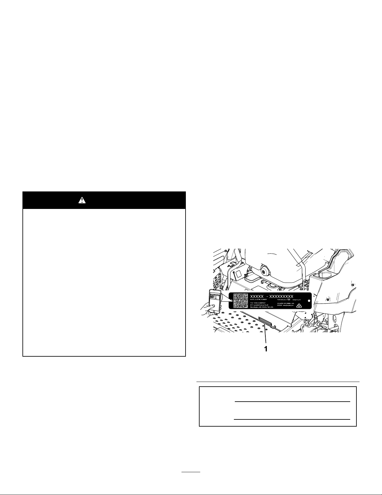
andserialnumbersofyourproductready.Figure1
identiesthelocationofthemodelandserialnumbers
ontheproduct.Writethenumbersinthespace
provided.
Important:Withyourmobiledevice,youcan
scantheQRcode(ifequipped)ontheserial
numberdecaltoaccesswarranty,parts,andother
productinformation.
Useofthisproductmaycauseexposure
tochemicalsknowntotheStateof
Californiatocausecancer,birthdefects,
orotherreproductiveharm.
©2018—TheToro®Company
8111LyndaleAvenueSouth
Bloomington,MN55420
Figure1
1.Modelandserialnumberlocation
ModelNo.
SerialNo.
Thismanualidentiespotentialhazardsandhas
safetymessagesidentiedbythesafety-alertsymbol
(Figure2),whichsignalsahazardthatmaycause
Contactusatwww.Toro.com.
2
g235670
PrintedintheUSA
AllRightsReserved
Page 3

seriousinjuryordeathifyoudonotfollowthe
recommendedprecautions.
Figure2
Safety-alertsymbol
Thismanualuses2wordstohighlightinformation.
Importantcallsattentiontospecialmechanical
informationandNoteemphasizesgeneralinformation
worthyofspecialattention.
Contents
Safety.......................................................................4
GeneralSafety...................................................4
g000502
SlopeIndicator...................................................5
SafetyandInstructionalDecals..........................6
ProductOverview...................................................13
Controls...........................................................14
HorizonDisplayMonitor................................14
Specications..................................................15
BeforeOperation.................................................16
BeforeOperationSafety...................................16
AddingFuel......................................................17
PerformingDailyMaintenance..........................18
BreakinginaNewMachine..............................18
UsingtheRolloverProtectionSystem
(ROPS).........................................................18
UsingtheSafety-InterlockSystem....................19
PositioningtheSeat..........................................20
UnlatchingtheSeat..........................................20
ChangingtheSeatSuspension.........................20
DuringOperation.................................................21
DuringOperationSafety...................................21
OperatingtheParkingBrake.............................23
OperatingtheMowerBlade-ControlSwitch
(PTO)............................................................23
StartingtheEngine...........................................24
ShuttingOfftheEngine.....................................24
UsingtheMotion-ControlLevers.......................25
DrivingtheMachine..........................................25
UsingtheSideDischarge.................................27
AdjustingtheHeightofCut...............................27
AdjustingtheAnti-ScalpRollers........................28
AdjustingtheFlowBafeCamLocks................29
PositioningtheFlowBafe................................29
AdjustingtheSkids...........................................30
OperatingwiththeOverheatSensor.................30
OperatingTips.................................................31
AfterOperation....................................................32
AfterOperationSafety......................................32
TransportingtheMachine.................................32
Maintenance...........................................................34
RecommendedMaintenanceSchedule(s)...........34
Pre-MaintenanceProcedures..............................35
MaintenanceSafety..........................................35
Lubrication..........................................................36
GreasingtheMachine.......................................36
LubricatingtheDriveU-JointsandSplined
SlipJoint.......................................................36
LubricatingtheCasterPivots............................37
LubricatingtheCaster-WheelHubs..................37
EngineMaintenance...........................................38
EngineSafety...................................................38
ServicingtheAirCleaner..................................38
ServicingtheEngineOil....................................39
FuelSystemMaintenance...................................41
DrainingtheFuelFilter/WaterSeparator...........41
ChangingtheWaterSeparator.........................41
3
Page 4

InspectingtheEngine-ValveClearance............42
CheckingtheFuelLinesand
Connections..................................................42
ElectricalSystemMaintenance...........................42
ElectricalSystemSafety...................................42
ServicingtheBattery.........................................42
ServicingtheFuses..........................................44
DriveSystemMaintenance..................................44
ReleasingtheDriveWheelRelease
Valves...........................................................44
AdjustingtheTracking......................................45
CheckingtheTirePressure...............................46
CheckingtheWheelLugNuts...........................46
AdjustingtheCaster-PivotBearing...................46
ServicingtheGearbox......................................47
CoolingSystemMaintenance..............................48
CoolingSystemSafety.....................................48
CheckingtheCoolingSystem...........................48
CleaningtheRadiator.......................................48
ChangingtheEngineCoolant...........................48
BrakeMaintenance.............................................49
AdjustingtheParkingBrake..............................49
BeltMaintenance................................................51
InspectingtheBelts..........................................51
ReplacingtheMowerBelt.................................51
CheckingtheAlternator-BeltTension................52
ControlsSystemMaintenance.............................52
AdjustingtheControl-HandlePosition..............52
AdjustingtheMotion-ControlLinkage...............53
AdjustingtheMotion-ControlDamper...............54
HydraulicSystemMaintenance...........................54
HydraulicSystemSafety...................................54
ServicingtheHydraulicSystem........................54
MowerDeckMaintenance....................................56
LevelingtheMowerDeck..................................56
ServicingtheCuttingBlades.............................59
ReplacingtheGrassDeector..........................62
Cleaning..............................................................62
CleaningtheEngineandExhaustSystem
Area..............................................................62
CleaningtheMachineandMower
Deck..............................................................62
DisposingofWaste...........................................62
Storage...................................................................63
StorageSafety..................................................63
CleaningandStoringtheMachine....................63
Troubleshooting......................................................64
Schematics.............................................................66
Safety
Thismachinehasbeendesignedinaccordancewith
ANSIB71.4-2012.
GeneralSafety
Thisproductiscapableofamputatinghandsand
feetandofthrowingobjects.Alwaysfollowallsafety
instructionstoavoidseriouspersonalinjury.
Usingthisproductforpurposesotherthanitsintended
usecouldprovedangeroustoyouandbystanders.
•Alwayskeeptherollbarinthefullyraisedand
lockedpositionandusetheseatbelt.
•Useyourfullattentionwhileoperatingthe
machine.Donotengageinanyactivitythat
causesdistractions;otherwise,injuryorproperty
damagemayoccur.
•Donotoperatethemachineneardrop-offs,
ditches,embankments,water,orotherhazards,or
onslopesgreaterthan15degrees.
•Readandunderstandthecontentsofthis
Operator’sManualbeforestartingtheengine.
•Donotputyourhandsorfeetnearmoving
componentsofthemachine.
•Donotoperatethemachinewithoutallguards
andothersafetyprotectivedevicesinplaceand
workingonthemachine.
•Keepchildrenandbystandersoutoftheoperating
area.Neverallowchildrentooperatethemachine.
•Stopthemachine,shutofftheengine,andremove
thekeybeforeservicing,fueling,orunclogging
themachine.
Improperlyusingormaintainingthismachinecan
resultininjury .T oreducethepotentialforinjury,
complywiththesesafetyinstructionsandalwayspay
attentiontothesafety-alertsymbol,whichmeans
Caution,Warning,orDanger—personalsafety
instruction.Failuretocomplywiththeseinstructions
mayresultinpersonalinjuryordeath.
Youcanndadditionalsafetyinformationwhere
neededthroughoutthismanual.
4
Page 5
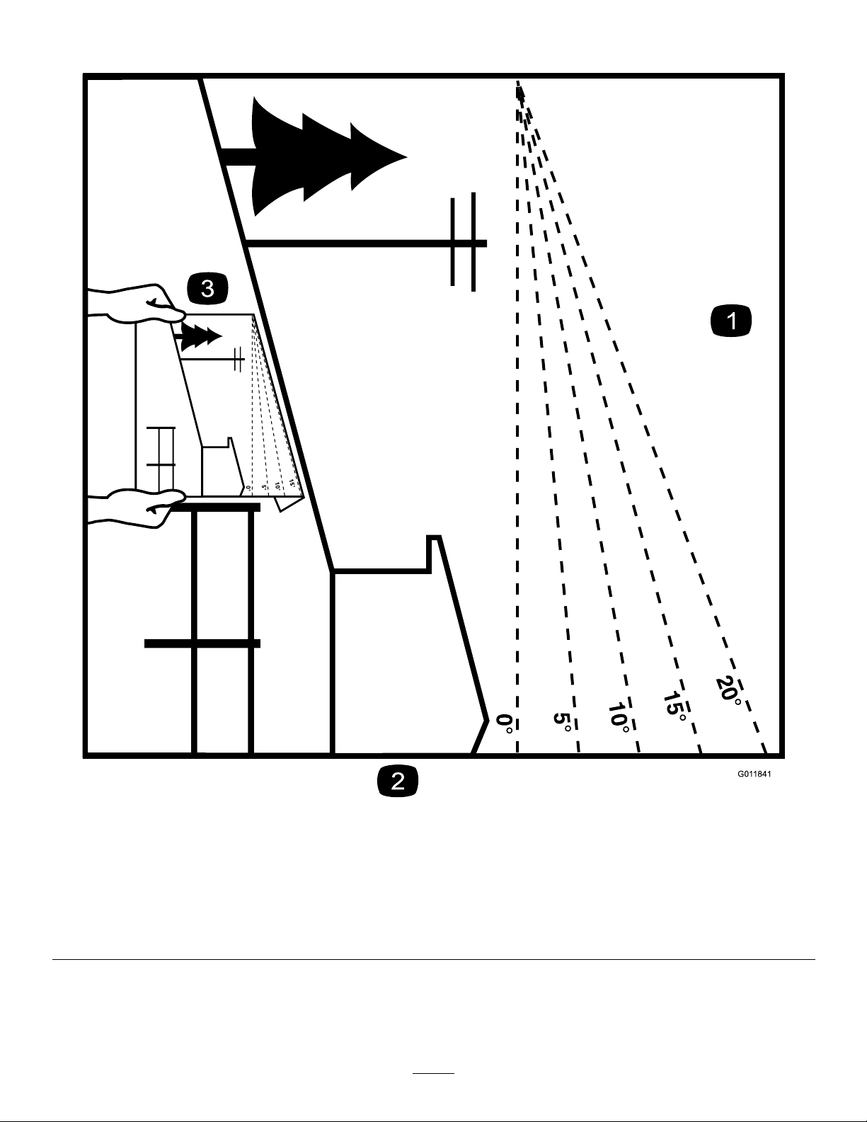
SlopeIndicator
Figure3
Youmaycopythispageforpersonaluse.
1.Themaximumslopeyoucanoperatethemachineonis15degrees.Usetheslopecharttodeterminethedegreeofslopeof
hillsbeforeoperating.Donotoperatethismachineonaslopegreaterthan15degrees.Foldalongtheappropriateline
tomatchtherecommendedslope.
2.Alignthisedgewithaverticalsurface,atree,building,fencepole,etc.
3.Exampleofhowtocompareslopewithfoldededge
5
g011841
Page 6
SafetyandInstructionalDecals
Safetydecalsandinstructionsareeasilyvisibletotheoperatorandarelocatednearanyarea
ofpotentialdanger.Replaceanydecalthatisdamagedormissing.
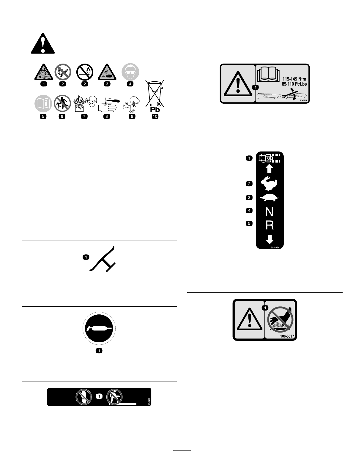
BatterySymbols
Someorallofthesesymbolsareonyourbattery .
decal93-7818
93-7818
decalbatterysymbols
1.Warning—readtheOperator'sManualforinstructionson
torquingthebladebolt/nutto1 15to149N∙m(85to110
ft-lb).
1.Explosionhazard
6.Keepbystandersasafe
distanceawayfromthe
battery.
2.Nore,opename,or
smoking
7.Weareyeprotection;
explosivegasescan
causeblindnessandother
injuries.
3.Causticliquid/chemical
burnhazard
8.Batteryacidcancause
blindnessorsevereburns.
4.Weareyeprotection.9.Flusheyesimmediately
withwaterandgetmedical
helpfast.
5.ReadtheOperator's
Manual.
10.Containslead;donot
discard
Manufacturer'sMark
1.Indicatesthebladeisidentiedasapartfromtheoriginal
machinemanufacturer.
decal99-8936
99-8936
decaloemmarkt
1.Machinespeed4.NEUTRAL
2.FAST5.REVERSE
3.SLOW
1.Grease
1.Donotstephere.
decal106-5517
106-5517
decal58-6520
58-6520
decal93-6687
1.Warning—donottouchthehotsurface.
93-6687
6
Page 7
decal112-9028
112-9028
1.Warning—stayawayfrommovingparts;keepallguardsin
place.
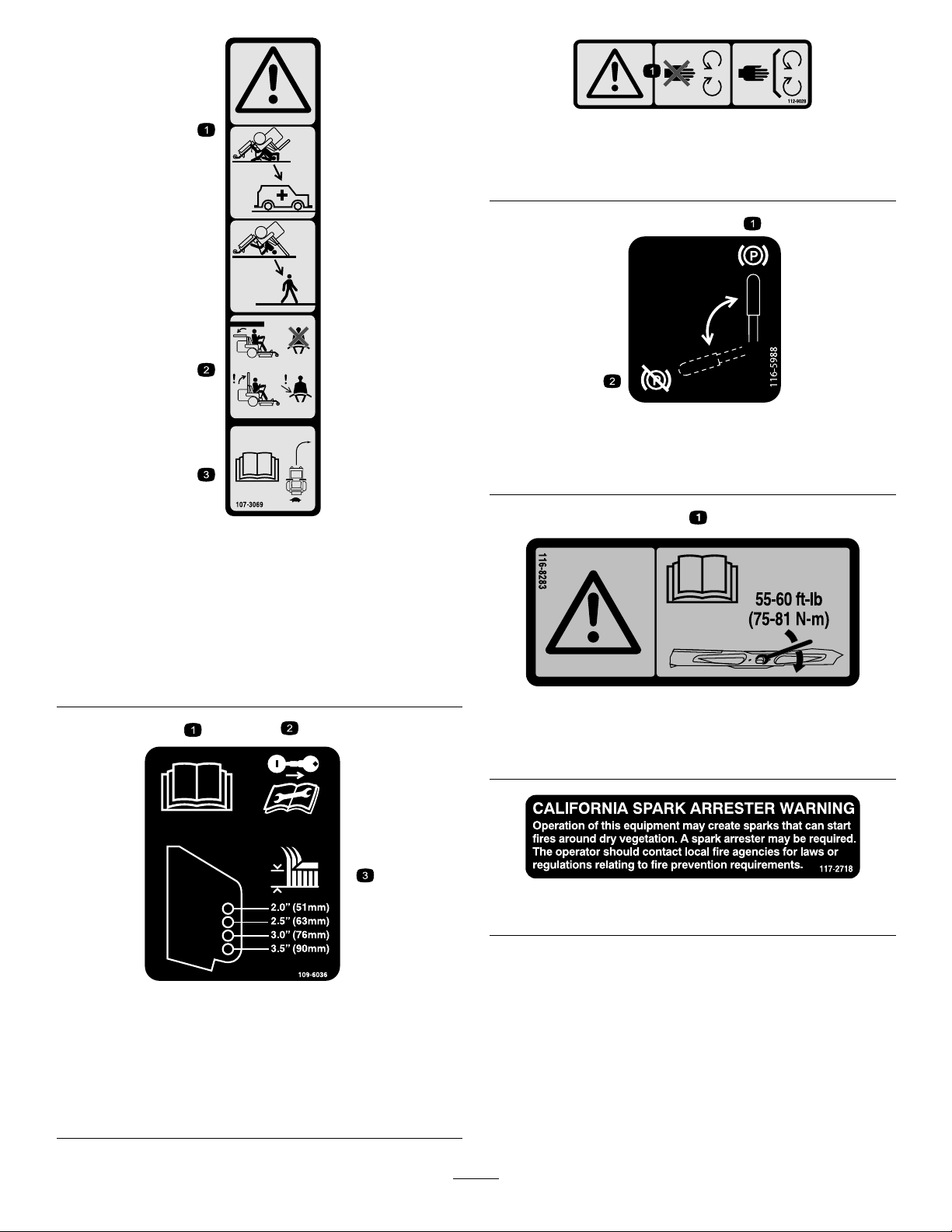
decal116-5988
116-5988
decal107-3069
107-3069
1.Warning—thereisnorolloverprotectionwhentherollbaris
down.
2.Toavoidinjuryordeathfromarolloveraccident,keepthe
rollbarinthefullyraisedandlockedpositionandwear
theseatbelt.Lowertherollbaronlywhenabsolutely
necessary;donotweartheseatbeltwhentherollbaris
down.
3.ReadtheOperator'sManual;driveslowlyandcarefully .
1.Parkingbrake—engaged2.Parking
brake—disengaged
decal116-8283
116-8283
1.Warning—readtheOperator'sManualforinstructionson
torquingthebladebolt/nutto75to81N∙m(55to60ft-lb).
decal117-2718
117-2718
109-6036
RearDischargeMachinesOnly
1.ReadtheOperator’sManual.
2.Removethekeyandreadtheinstructionsbeforeservicing
orperformingmaintenance.
3.Heightofcut
decal109-6036
7
Page 8
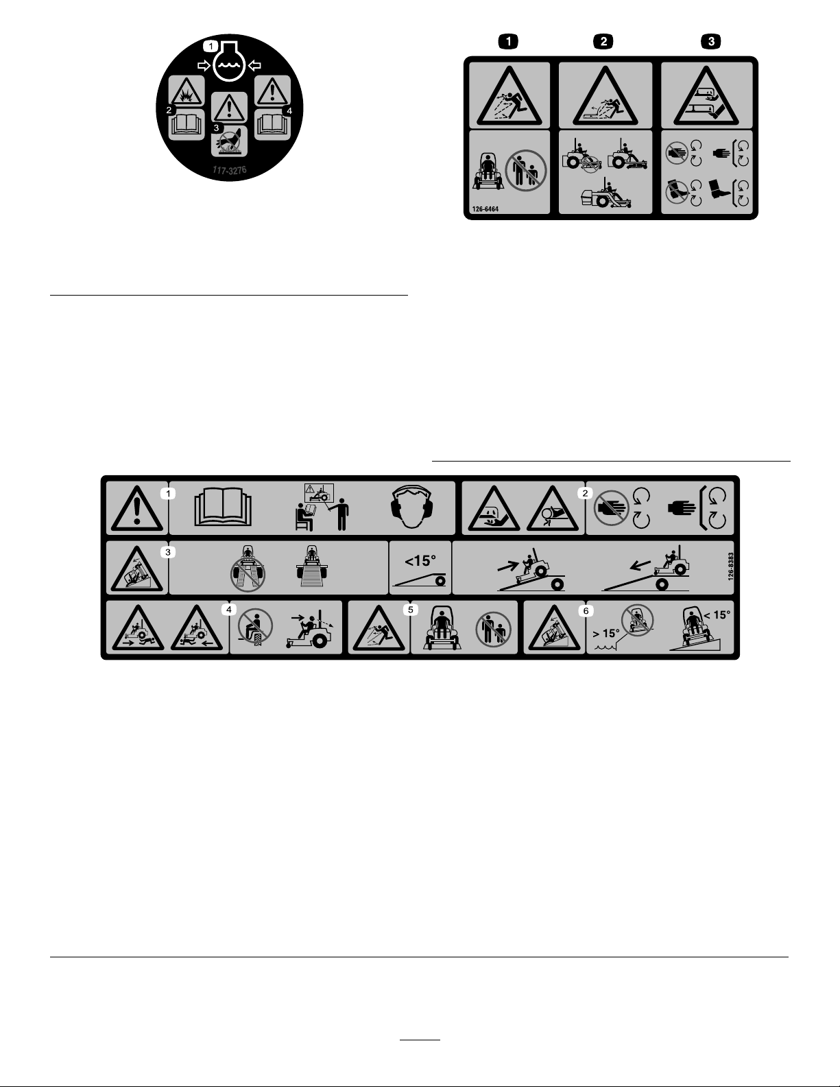
1.Enginecoolantunder
pressure
2.Explosionhazard—read
theOperator'sManual.
117-3276
3.Warning—donottouchthe
hotsurface.
4.Warning—readthe
Operator'sManual.
decal117-3276
decal126-6464
126-6464
ForModelswithSideDischarge
1.Thrownobjects
hazard—keepbystanders
asafedistanceawayfrom
themachine.
2.Thrownobjects
hazard—mower;do
notoperatethemachine
withoutthedeector,
dischargecover,or
grass-collectionsystemin
place.
3.Cutting/dismembermentof
handorfoot—stayaway
frommovingparts;keep
allguardsandshieldsin
place.
126-8383
MachineswithoutMyRideOnly
Note:Thismachinecomplieswiththeindustrystandardstabilitytestinthestaticlateralandlongitudinaltestswiththemaximum
recommendedslopeindicatedonthedecal.ReviewtheinstructionsforoperatingthemachineonslopesintheOperator’sManualas
wellastheconditionsinwhichyouwouldoperatethemachinetodeterminewhetheryoucanoperatethemachineinthoseconditions
onthatdayandatthatsite.Changesintheterraincanresultinachangeinslopeoperationforthemachine.Ifpossible,keepthe
cuttingunitsloweredtothegroundwhileoperatingthemachineonslopes.Raisingthecuttingunitswhileoperatingonslopescan
causethemachinetobecomeunstable.
1.Warning—readtheOperator’sManual;donotoperatethis
machineunlessyouaretrained;wearhearingprotection.
2.Cutting,dismembering,andentanglementhazard—keep
handsawayfrommovingparts;keepallguardsandshieldsin
place.
3.Ramphazard—whenloadingontoatrailer,donotusedual
ramps;onlyuseasingularrampwideenoughforthemachine
andthathasaninclinelessthan15°;backuptheramp(in
reverse)anddriveforwardofftheramp.
4.Bodilyharmhazard—donotcarrypassengers;lookbehind
youwhenmowinginreverse.
5.Thrownobjecthazard—keepbystandersaway .
6.Tippinghazardonslopes—donotuseonslopesnearopen
water;donotuseonslopesgreaterthan15°.
8
decal126-8383
Page 9
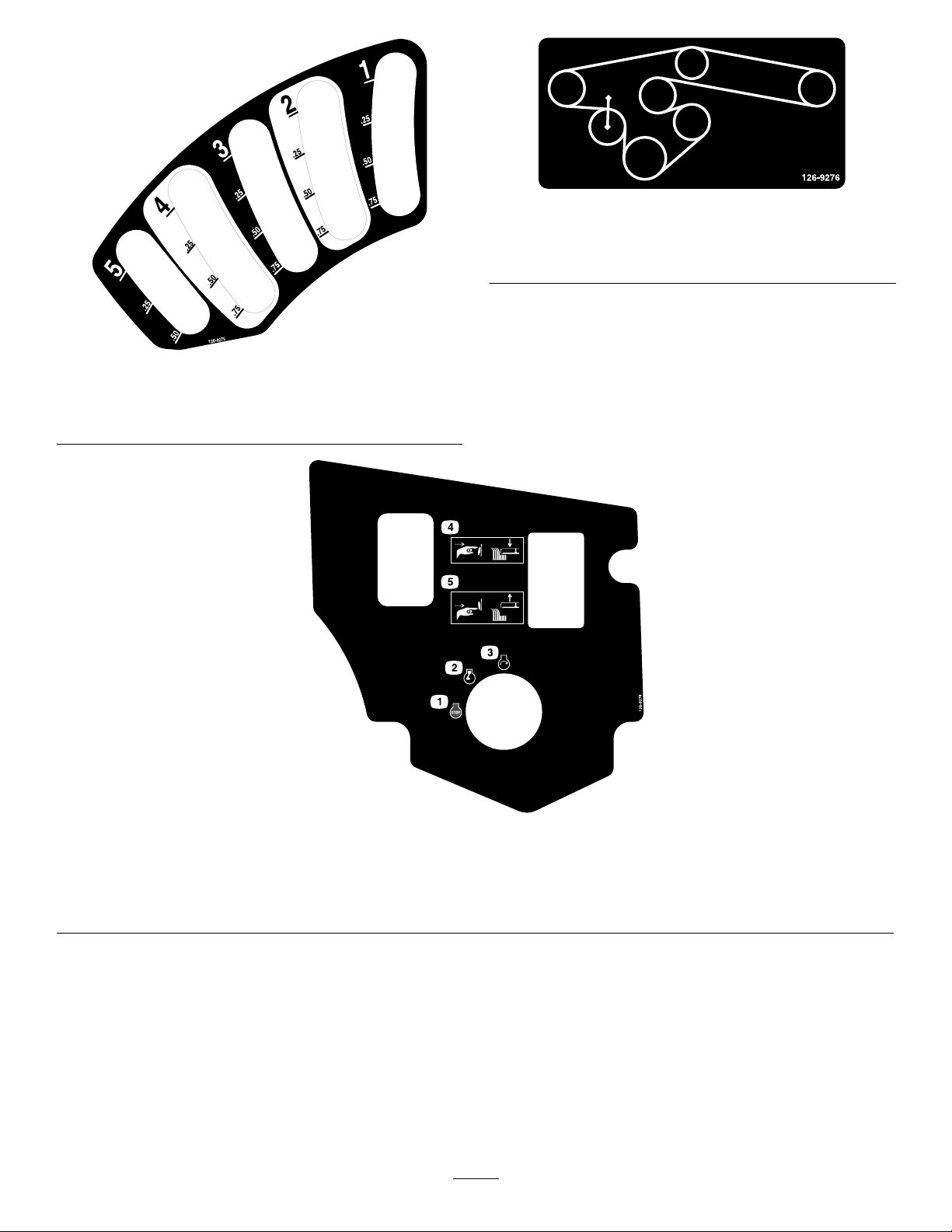
126-9275
ForModelswith152cm(60-inch)or183cm(72-inch)
Decks
decal126-9276
126-9276
ForModelswith183cm(72-inch)DeckswithSide
Discharge
decal126-9275
126-9278
1.Engine—Off4.Pushthebottomofthebuttontolowerthedeck.
2.Engine—On5.Pushthetopofthebuttontoraisethedeck.
3.Engine—Start
9
decal126-9278
Page 10
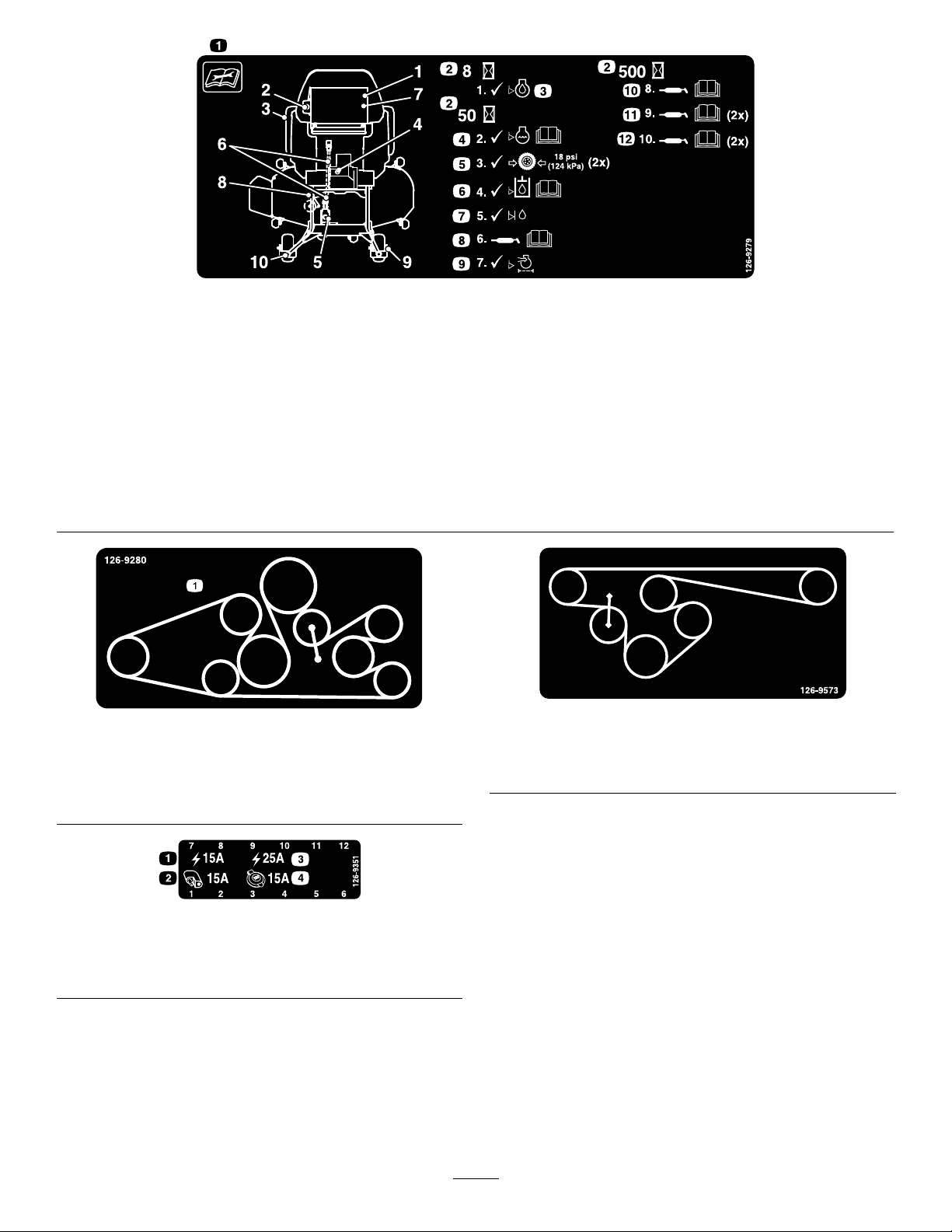
decal126-9279
126-9279
1.Readtheinstructionsbeforeservicingorperforming
7.Checkthejackshaft-uidlevel.
maintenancetothemachine.
2.Timeinterval
8.Greasethedeck-drivePTO;refertotheOperator'sManual
forfurtherinstructions.
3.Checktheengine-oillevel.9.Checktheaircleaner.
4.Checkthecoolantlevel;refertotheOperator'sManualfor
furtherinstructions.
10.Greasetheidlerpivot;refertotheOperator'sManualfor
furtherinstructions
5.Checkthetirepressure(2locations).11.Greasethefrontcasterwheelbearings(2locations);referto
theOperator'sManualforfurtherinstructions.
6.Checkhydraulic-uidlevel;refertotheOperator'sManual
forfurtherinstructions.
decal126-9280
126-9280
ForModelswith152cm(60-inch)or183cm(72-inch)
DeckswithRearDischarge
12.Greasethefrontcasterpivots(2locations);refertothe
Operator'sManualforfurtherinstructions.
decal126-9573
126-9573
ForModelswith152cm(60-inch)DeckswithSide
Discharge
1.Beltrouting
126-9351
1.Chassis(15A)3.Main(25A)
2.Accessory(15A)4.Powerpoint(15A)
decal126-9351
10
Page 11
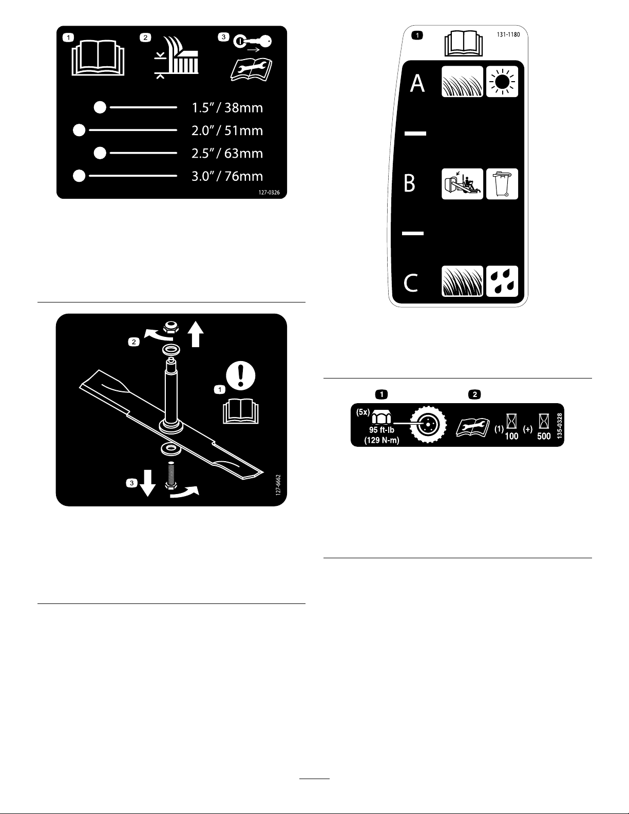
decal127-0326
127-0326
1.ReadtheOperator's
Manual.
2.Heightofcut
RearDischargeMowersOnly
1.Attention—readthe
Operator'sManual.
2.Removethenutbyturning
itclockwise.
3.Removethekeyand
127-6662
3.Removetheboltbyturning
readtheOperator's
Manualbeforeperforming
maintenanceorservicing
themachine.
itcounterclockwise.
decal131-1180
131-1180
1.ReadtheOperator'sManual.(A)Short,lightgrass;dry
conditions;maximumdispersion;(B)Baggingsetting;(C)
Tall,densegrass;wetconditions;maximumgroundspeed
decal135-0328
135-0328
1.Torquethewheellugnuts
to129N∙m(95ft-lb).
decal127-6662
2.Readandunderstand
theOperator'sManual
beforeperformingany
maintenance;checkthe
torqueaftertherst100
hours,thenevery500
hours,thereafter.
11
Page 12
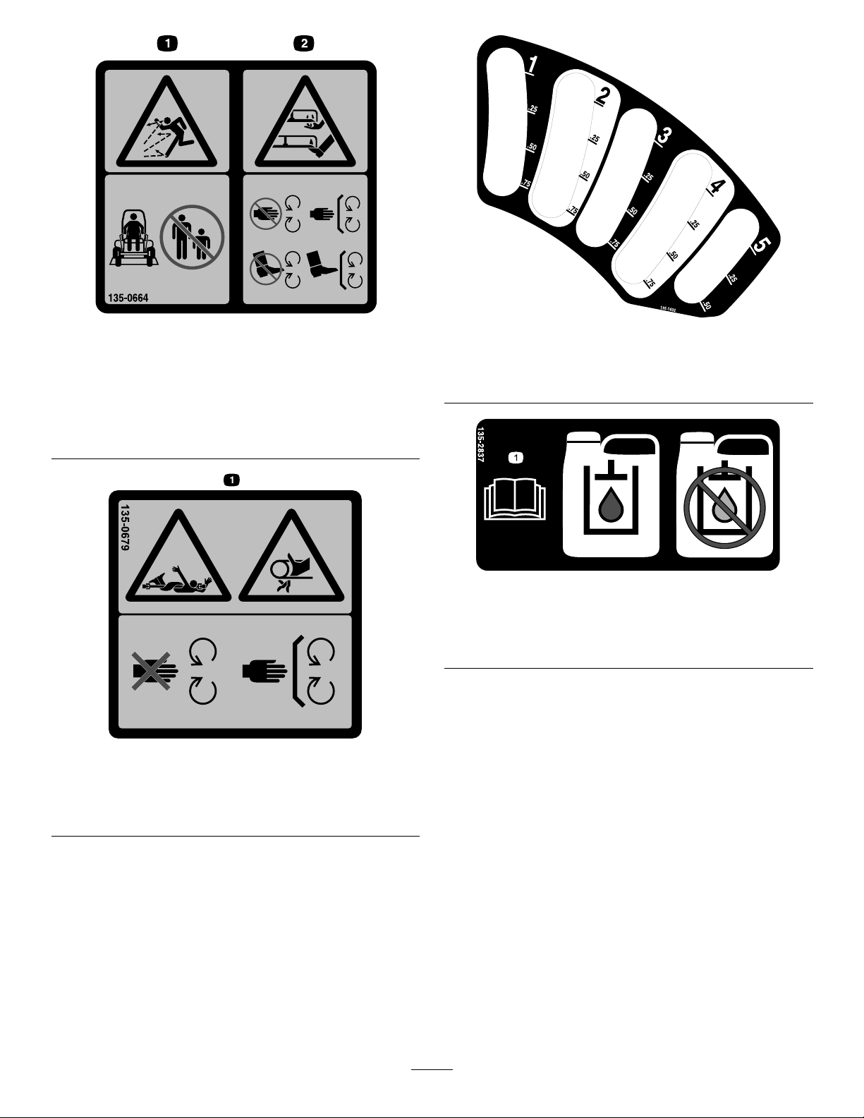
1.Thrownobjects
hazard—keepbystanders
asafedistanceawayfrom
themachine.
135-0664
RearDischargeMowersOnly
2.Cutting/dismembermentof
decal135-0664
handandfeet—stayaway
frommovingparts;keep
allguardsandshieldsin
place.
decal135-1432
135-1432
ForModelswith152cm(60-inch)or183cm(72-inch)
Decks
decal135-2837
135-2837
1.ReadtheOperator’sManualformoreinformation;Use
redTorowet-clutchtransmissionuid;donotusegreen
hydraulicuid.
135-0679
1.Rotatingdrivelinehazard/entanglementhazard;belt—stay
awayfrommovingparts;keepallguardsandshieldsin
place.
decal135-0679
12
Page 13
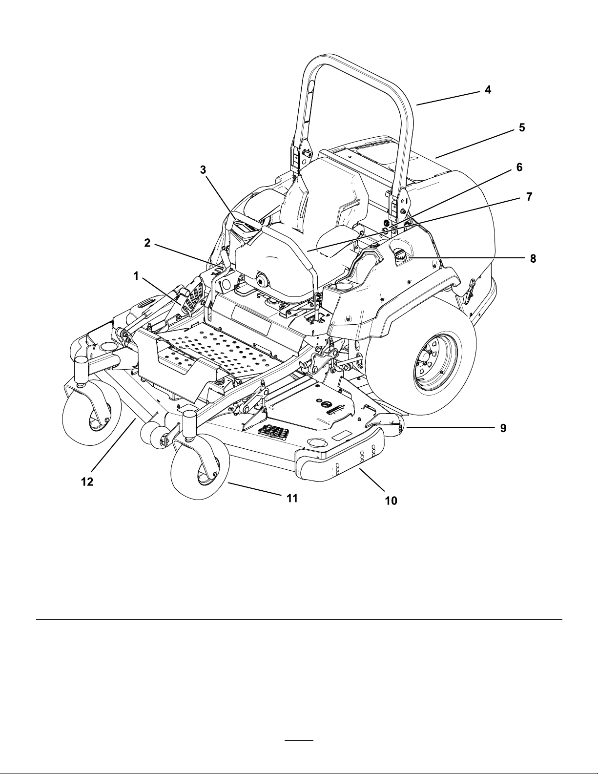
ProductOverview
Figure4
1.Height-of-cutpin
2.Parking-brakelever8.Fuel-tankcap
3.Monitor/controls
4.Rollbar
5.Enginescreen
6.Audiblealarmandpowerpoint12.Mowerdeck
7.Motion-controllever
9.Anti-scalproller
10.Skid
11.Casterwheel
13
g227303
Page 14
Controls
Becomefamiliarwithallthecontrolsbeforeyoustart
theengineandoperatethemachine.
InformationScreen
Theinformationscreendisplaysinformationrelative
tomachineoperation;refertotheSoftwareGuidefor
moreinformation.
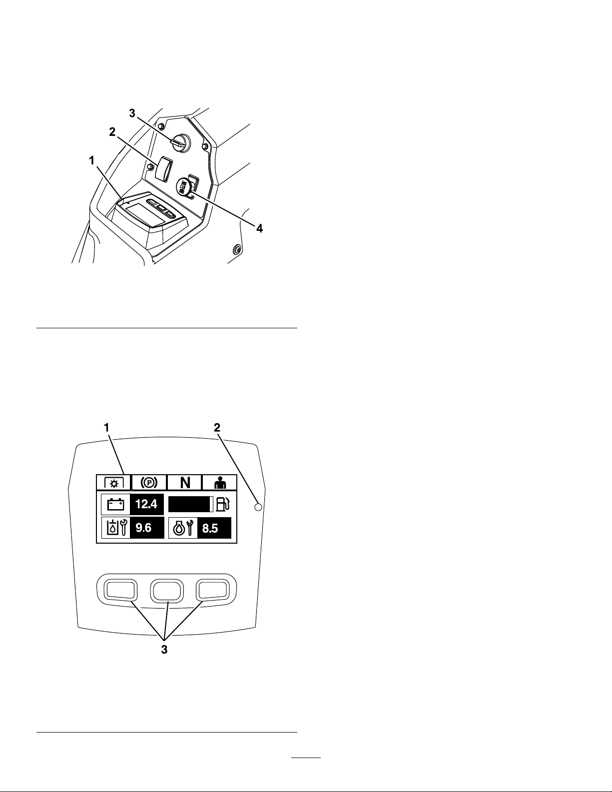
ControlPanel
Figure5
1.Horizondisplaymonitor3.Keyswitch
2.Deck-leftswitch4.PTO
HorizonDisplayMonitor
RefertotheSoftwareGuidefordetailedinformation
explainingtheoperatorinterfacethatallowsyouto
accessinformation,resetcounters,modifysystem
settings,andtroubleshoottheequipment.
Buttons
Themulti-functionalbuttonsarelocatedatthebottom
ofthepanel.Theiconsdisplayedontheinformation
screenabovethebuttonsindicatethecurrentfunction.
Thebuttonsallowyoutoselecttheenginespeedand
navigatethroughsystemmenus.
RefertotheSoftwareGuideformoreinformation.
LEDStatusLight
TheLEDstatuslightismulti-coloredtoindicatethe
systemstatusandislocatedontherightsideofthe
panel.Duringstartup,theLEDilluminatesredto
g225792
orangetogreentoverifyfunctionality.
•Solidgreen—indicatesnormaloperatingactivity
•Blinkingred—indicatesanactivefault
•Blinkinggreenandorange—indicatesthata
clutchresetisrequired
RefertotheSoftwareGuideformoreinformation.
Alarm
Ifanerroroccurs,anerrormessagedisplays,theLED
turnsred,andthealarmsoundsaudiblyasfollows:
1.Screen
2.LEDstatuslight
HorizonDisplayMonitor
Figure6
•Afastchirpsoundindicatescriticalerrors.
•Aslowchirpingsoundindicateslesscriticalerrors,
suchasrequiredmaintenanceorserviceintervals.
Note:Duringstartup,thealarmsoundsbrieyto
verifyfunctionality.
RefertotheSoftwareGuideformoreinformation.
HourMeter
Thehourmeterrecordsthenumberofhoursthe
enginehasoperated.Itoperateswhentheengine
isrunning.Usethesetimesforschedulingregular
maintenance(Figure5).
HoursaredisplayedinEngine-Offscreenorinthe
EngineHourCountermenu.
RefertotheSoftwareGuideformoreinformation.
g228164
ThrottleControl
3.Buttons
Thethrottlecontrolstheenginespeed,andthereare
3speeds:Maximum,Efcient,andLow.
RefertotheSoftwareGuideformoreinformation.
14
Page 15

Deck-LiftSwitch
Attachments/Accessories
Presstheswitchrearwardtoraisethedeck.
Presstheswitchforwardtolowerthedeck.
Blade-ControlSwitch(Power
Takeoff)
Theblade-controlswitch(PTO)engagesand
disengagespowertothemowerblades(Figure5).
TheLCDindicatorappearsontheinformationscreen
whenthePTOswitchisdisengaged.
Note:MachinesequippedwiththeHorizonDisplay
Monitorhaveaclutchsaver,whichallowsthethrottle
toautomaticallyreducetheenginespeedwhen
youdisengagethePTOswitch.Engagingand
disengagingthePTOswitchchangestheengine
throttlebetweenMOWandTRANSPORTmode.
Note:Thesystemallowsyoutostartthemachine
withthePTOswitchengaged,butdoesnotengage
theblades.EngagingthePTOrequiresyoutoreset
thePTOswitchbydisengaging,thenengagingit.
Neutral-LockPosition
AselectionofT oroapprovedattachmentsand
accessoriesisavailableforusewiththemachine
toenhanceandexpanditscapabilities.Contact
yourAuthorizedServiceDealerorauthorizedT oro
distributororgotowww.Toro.comforalistofall
approvedattachmentsandaccessories.
Toensureoptimumperformanceandcontinuedsafety
certicationofthemachine,useonlygenuineT oro
replacementpartsandaccessories.Replacement
partsandaccessoriesmadebyothermanufacturers
couldbedangerous,andsuchusecouldvoidthe
productwarranty.
Specications
OverallWidth—SideDischargeMachines
60-inchDeck72-inchDeck
Withoutthedeck
Deectorup156cm(61.4
Deectordown184.9cm(72.8
141.2cm(55.6
inches)
inches)
inches)
152.4cm(60
inches)
186.4cm(73.4
inches)
215.6cm(84.9
inches)
UsetheNEUTRAL-LOCKpositionwiththe
safety-interlocksystemtoengageandtodetermine
theNEUTRALposition.
KeySwitch
Usethisswitchtostarttheengine.Ithas3positions:
START,RUN,andOFF.
Note:TheLCDindicatorsappearwheneachcontrol
meetsthe“safetostart”mode(e.g.,theindicator
turnsonwhenyouareintheseat.)
Note:TheengineECUcontrolstheglowplugsduring
coldstarts.Ifthecoolanttemperatureistoolow,the
glowsymboldisplaysonthemonitorandthestarter
doesnotcrankwhenyouturntheenginetotheSTART
position.TheglowplugsactivateintheONorSTART
position.Oncetheglowhasbeenonlongenough
forthecurrenttemperature,theglowsymbolonthe
monitordisappearsandtheenginecrankswhen
turnedtotheST ARTposition.
Note:Thesystemallowsyoutostartthemachinethe
withthePTOswitchengaged,butdoesnotengage
theblades.YoumustresetthePTOtoengagethe
PTO.
OverallWidth—RearDischargeMachines
60-inchDeck72-inchDeck
168.2cm(66.2inches)198.7cm(78.2inches)
OverallLength—SideDischargeMachines
60-inchDeck72-inchDeck
Rollbarupordown
244.9cm(96.4
inches)
OverallLength—RearDischargeMachines
Rollbarupordown
255.5cm(100.6inches)
OverallHeight—AllMachines
Rollbarup
Rollbardown
182.4cm(71.8inches)
129.5cm(51inches)
OverallHeight—AllMachines
Rollbarup
Rollbardown
182.4cm(71.8inches)
129.5cm(51inches)
TreadWidthofDriveWheels—AllMachines
112cm(44.1inches)
253cm(99.6
inches)
15
Page 16

TreadWidthofCasterWheels
(Center-to-CenterofTires)—SideDischarge
Machines
60-inchDeck72-inchDeck
101.3cm(39.9inches)120.7cm(47.5inches)
Operation
Note:Determinetheleftandrightsidesofthe
machinefromthenormaloperatingposition.
TreadWidthofCasterWheels
(Center-to-CenterofTires)—RearDischarge
Machines
60-inchDeck72-inchDeck
84cm(33.1inches)84cm(33.1inches)
WheelBase(CenterofCasterTiretoCenterof
DriveTire)—SideDischargeMachines
60-inchDeck72-inchDeck
146.3cm(57.6inches)154.7cm(60.9inches)
WheelBase(CenterofCasterTiretoCenterof
DriveTire)—RearDischargeMachines
60-inchDeck72-inchDeck
157.2cm(61.9inches)157.2cm(61.9inches)
BeforeOperation
BeforeOperationSafety
GeneralSafety
•Neverallowchildrenoruntrainedpeopleto
operateorservicethemachine.Localregulations
mayrestricttheageoftheoperator.Theowner
isresponsiblefortrainingalloperatorsand
mechanics.
•Becomefamiliarwiththesafeoperationofthe
equipment,operatorcontrols,andsafetysigns.
•Knowhowtostopthemachineandshutoffthe
enginequickly.
•Checkthatoperator-presencecontrols,safety
switches,andshieldsareattachedandfunctioning
properly.Donotoperatethemachineunlessthey
arefunctioningproperly.
•Beforemowing,alwaysinspectthemachineto
ensurethattheblades,bladebolts,andcutting
assembliesareingoodworkingcondition.
Replacewornordamagedbladesandboltsinsets
topreservebalance.
•Inspecttheareawhereyouwillusethemachine
andremoveallobjectsthatthemachinecould
throw.
•Evaluatetheterraintodeterminetheappropriate
equipmentandanyattachmentsoraccessories
requiredtooperatethemachineproperlyand
safely.
FuelSafety
•Toavoidpersonalinjuryorpropertydamage,use
extremecareinhandlingfuel.Fuelvaporsare
ammableandexplosive.
•Extinguishallcigarettes,cigars,pipes,andother
sourcesofignition.
•Useonlyanapprovedfuelcontainer.
•Donotremovethefuelcaporaddfueltothefuel
tankwhiletheengineisrunningorwhilehot.
•Donotrefuelthemachineindoors.
•Donotstorethemachineorfuelcontainerwhere
thereisanopename,spark,orpilotlight,such
asonawaterheateroronotherappliances.
•Donotllcontainersinsideavehicleoronatruck
ortrailerbedwithaplasticliner.Alwaysplace
16
Page 17

containersontheground,awayfromyourvehicle
beforelling.
•Removetheequipmentfromthetruckortrailer
andrefuelitwhileitisontheground.Ifthisisnot
possible,thenrefuelfromaportablecontainer
ratherthanafuel-dispensernozzle.
•Donotoperatethemachinewithouttheentire
exhaustsysteminplaceandinproperworking
condition.
•Keepthefuel-dispensernozzleincontactwith
therimofthefueltankorcontaineropeningat
alltimesuntilfuelingiscomplete.Donotusea
nozzlelock-opendevice.
•Ifyouspillfuelonyourclothing,changeyour
clothingimmediately.Wipeupanyfuelthatspills.
•Neveroverllthefueltank.Replacethefuelcap
andtightenitsecurely.
•Storefuelinanapprovedcontainerandkeepit
outofthereachofchildren.Neverbuymorethan
a30-daysupplyoffuel.
•Donotllthefueltankcompletelyfull.Addfuelto
thefueltankuntilthelevelis6to13mm(1/4to
1/2inch)belowthebottomofthellerneck.This
emptyspaceinthetankallowsfueltoexpand.
–Avoidprolongedbreathingofvapors.
–Keepyourfaceawayfromthenozzleandfuel
tankopening.
–Avoidcontactwithskin;washoffspillswith
soapandwater.
AddingFuel
RecommendedFuel
Theenginerunsonclean,freshdieselfuelwith
aminimumcetaneratingof40.Purchasefuelin
quantitiesthatcanbeusedwithin30daystoensure
fuelfreshness.
BiodieselReady
Thismachinecanalsouseabiodieselblendedfuel
ofuptoB20(20%biodiesel,80%petrodiesel).The
petrodieselportionshouldbeloworultralowsulfur.
Observethefollowingprecautions:
•Thebiodieselportionofthefuelmeetspecication
ASTMD6751orEN14214.
•TheblendedfuelcompositionshouldmeetASTM
D975orEN590.
•Paintedsurfacesmaybedamagedbybiodiesel
blends.
•UseB5(biodieselcontendof5%)orlesserblend
incoldweather.
•Monitorseals,hoses,gasketsincontactwithfuel
astheymaydegradeovertime.
•Fuellterpluggingmaybeexpectedforatime
afterconvertingtobiodieselblends.
•Contactyourdistributorifyouwishformore
informationonbiodiesel.
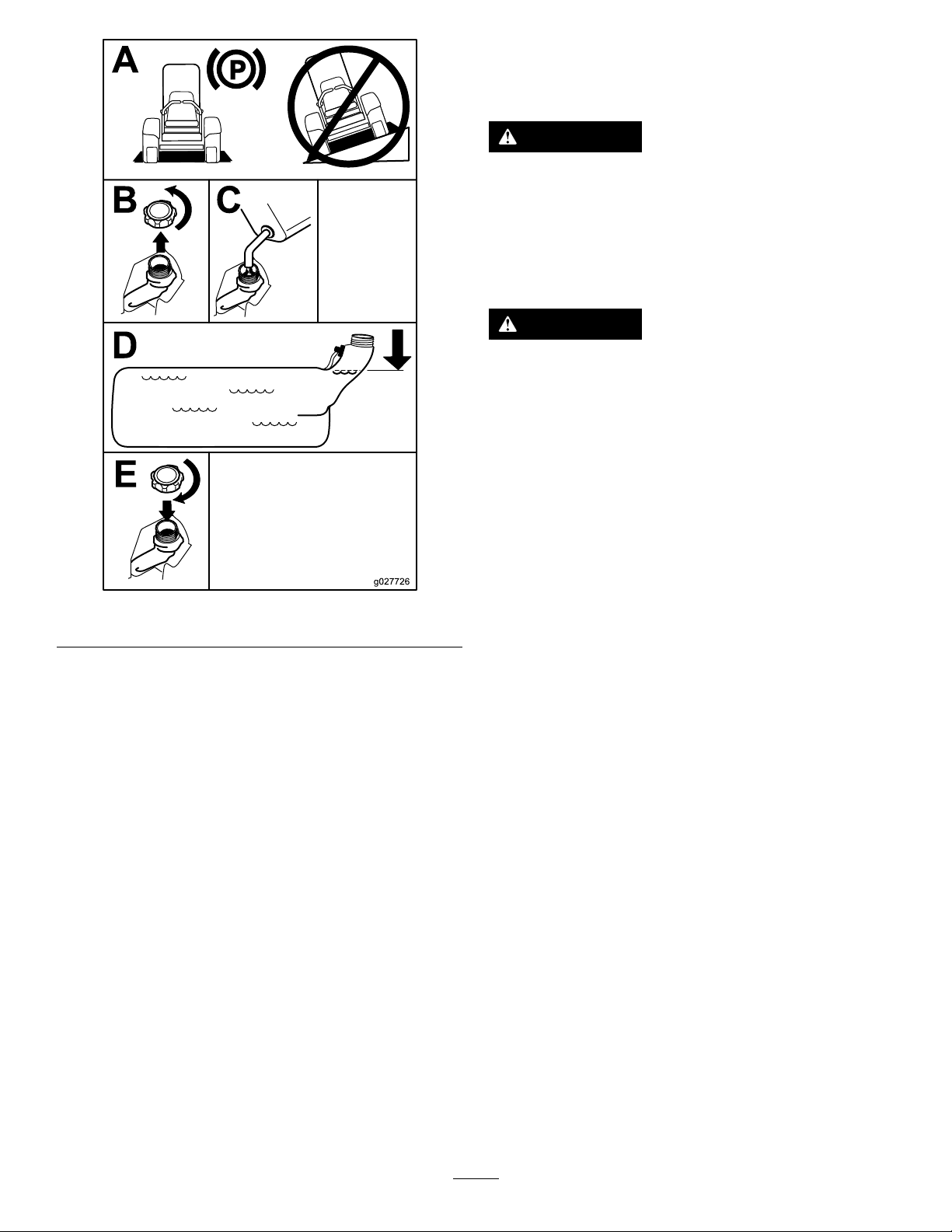
FillingtheFuelTank
1.Parkthemachineonlevelground.
2.Shutofftheengineandengagetheparking
brake.
3.Cleanaroundthefuel-tankcap.
4.Fillthefueltanktothebottomofthellerneck
(Figure7).
Note:Donotllthefueltankcompletelyfull.
Theemptyspaceinthetankallowsthefuelto
expand.
Usesummer-gradedieselfuel(No.2-D)at
temperaturesabove-7°C(20°F)andwinter-grade
dieselfuel(No.1-DorNo.1-D/2-Dblend)below
-7°C(20°F).Useofwinter-gradedieselfuelatlower
temperaturesprovideslowerashpointandpour
pointcharacteristics,thereforeeasingstartabilityand
lesseningchancesofchemicalseparationofthefuel
duetolowertemperatures(waxappearance,which
maypluglters).
Usingsummer-gradedieselfuelabove-7°C
(20°F)contributestowardlongerlifeofthepump
components.
Important:Donotusekeroseneorgasoline
insteadofdieselfuel.Failuretoobservethis
cautionwilldamagetheengine.
17
Page 18
UsingtheRollover ProtectionSystem(ROPS)
WARNING
Toavoidinjuryordeathfromrollover:keep
therollbarintheraisedlockedpositionand
usetheseatbelt.
Ensurethattherearpartoftheseatissecured
withtheseatlatch.
WARNING
Thereisnorolloverprotectionwhentheroll
barisinthedownposition.
•Lowertherollbaronlywhenabsolutely
necessary.
•Donotweartheseatbeltwhentherollbar
isinthedownposition.
•Driveslowlyandcarefully.
Figure7
PerformingDaily Maintenance
Beforestartingthemachineeachday ,performthe
EachUse/DailyprocedureslistedinMaintenance
(page34).
BreakinginaNewMachine
Newenginestaketimetodevelopfullpower.Mower
decksanddrivesystemshavehigherfrictionwhen
new,placingadditionalloadontheengine.Allow
40to50hoursofbreak-intimefornewmachinesto
developfullpowerandbestperformance.
•Raisetherollbarassoonasclearance
permits.
g027726
•Checkcarefullyforoverheadclearances
(i.e.,branches,doorways,electricalwires)
beforedrivingunderanyobjectsanddo
notcontactthem.
Important:Lowertherollbaronlywhen
absolutelynecessary.
1.Ensurethattheknobiscompletelylatchedwith
thetabsinterlockingasshowninFigure8tolock
therollbarintheraisedposition.
2.Tolowertherollbar,applyforwardpressureto
theupperpartoftherollbar.
3.Pullbothknobsoutandrotatethem90°sothey
arenotengaged(Figure8).
4.Toraisetherollbar,raisetherollbartothe
operateposition,rotatetheknobssothatthey
movepartiallyintothegrooves(Figure8).
5.Raisetherollbartothefulluprightpositionwhile
pushingontheupperrollbarandthepinssnap
intopositionwhentheholesalignwiththepins
(Figure8).
Important:Alwaysusetheseatbeltwiththe
rollbarintheraisedposition.
18
Page 19
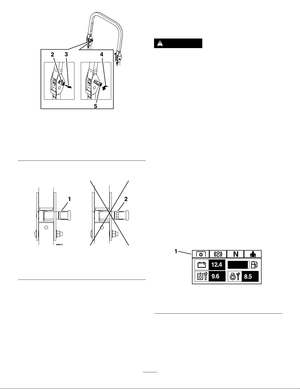
Figure8
1.Upperpartoftherollbar4.Rotatetheknobout90°
2.Knobinthelatched
position
3.Pulltheknobtounlatch.
toholditintheunlatched
position.
5.Knobintheunlatched
position
UsingtheSafety-Interlock System
WARNING
Ifthesafety-interlockswitchesare
disconnectedordamaged,themachinecould
operateunexpectedly,causingpersonal
injury.
•Donottamperwiththeinterlockswitches.
•Checktheoperationoftheinterlock
switchesdailyandreplaceanydamaged
switchesbeforeoperatingthemachine.
g225804
Understandingthe Safety-InterlockSystem
Thesafety-interlocksystemisdesignedtopreventthe
enginefromstartingunless:
•Theparkingbrakeisengaged.
6.Pushontherollbarandensurethatbothpins
areengaged(Figure9).
Figure9
1.Engaged2.Partiallyengaged—donot
operatethemachinewith
theROPSinthisposition.
•Theblade-controlswitch(PTO)isdisengaged.
•Themotion-controlleversareintheNEUTRAL-LOCK
position.
Thesafety-interlocksystemalsoisdesignedtoshut
offtheenginewhenthemotion-controlleversare
movedfromtheNEUTRAL-LOCKpositionwiththe
parkingbrakeengagedorifyourisefromtheseat
whenthePTOisengaged.
TheHorizonDisplayMonitorhassymbolstonotify
theuserwhentheinterlockcomponentisinthe
correctposition.Whenthecomponentisinthecorrect
position,thecorrespondingsymboldisplaysonthe
g008619
monitor.
g230650
Figure10
1.Symbolsdisplayonthemonitorwhentheinterlock
componentsareinthecorrectposition.
19
Page 20
TestingtheSafety-Interlock System
ServiceInterval:Beforeeachuseordaily
Testthesafety-interlocksystembeforeyouusethe
machineeachtime.Ifthesafetysystemdoesnot
operateasdescribedbelow,haveanAuthorized
ServiceDealerrepairthesafetysystemimmediately .
1.Sitontheseat,engagetheparkingbrake,and
movetheblade-controlswitch(PTO)totheON
position.Trystartingtheengine;theengine
shouldnotstart.
2.Sitontheseat,engagetheparkingbrake,and
movetheblade-controlswitch(PTO)totheOFF
position.Moveeithermotion-controlleverout
oftheNEUTRAL-LOCKposition.Trystartingthe
engine;theengineshouldnotstart.Repeatfor
theothercontrollever.
3.Sitontheseat,engagetheparkingbrake,
movetheblade-controlswitch(PTO)totheOFF
position,andmovethemotion-controllevers
totheNEUTRAL-LOCKposition.Nowstartthe
engine.Whiletheengineisrunning,disengage
theparkingbrake,engagetheblade-control
switch(PTO),andriseslightlyfromtheseat;the
engineshouldshutoff.
4.Sitontheseat,engagetheparkingbrake,
movetheblade-controlswitch(PTO)totheOFF
position,andmovethemotion-controllevers
totheNEUTRAL-LOCKposition.Nowstartthe
engine.Whiletheengineisrunning,center
eithermotioncontrolandmove(forwardor
reverse);theengineshouldshutoff.Repeatfor
othermotioncontrol.
5.Sitontheseat,disengagetheparkingbrake,
movetheblade-controlswitch(PTO)totheOFF
position,andmovethemotion-controllevers
totheNEUTRAL-LOCKposition.Trystartingthe
engine;theengineshouldnotstart.
g019754
Figure11
UnlatchingtheSeat
g019755
Figure12
1.Seatlatch2.Seat
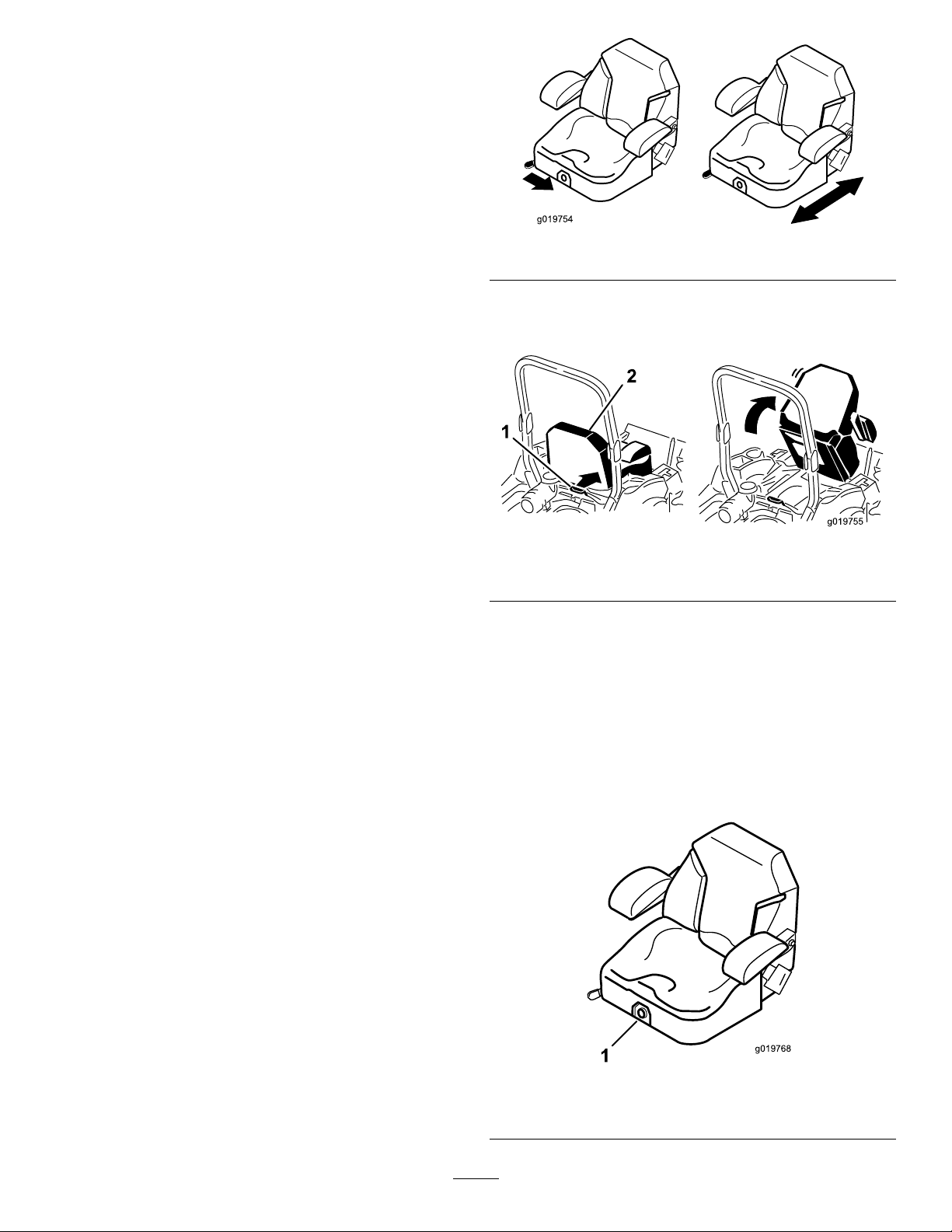
ChangingtheSeat Suspension
Theseatisadjustabletoprovideasmoothand
comfortableride.Positiontheseatwhereyouare
mostcomfortable.
Toadjustit,turntheknobinfronteitherdirectionto
providethebestcomfort(Figure13).
PositioningtheSeat
Theseatmovesforwardandbackward.Positionthe
seatwhereyouhavethebestcontrolofthemachine
andaremostcomfortable.
Toadjust,movetheleversidewaystounlocktheseat
(Figure11).
g019768
Figure13
1.Seat-suspensionknob
20
Page 21

DuringOperation
DuringOperationSafety
GeneralSafety
•Theowner/operatorcanpreventandisresponsible
foraccidentsthatmaycausepersonalinjuryor
propertydamage.
•Wearappropriateclothing,includingeye
protection;longpants;slip-resistant,substantial
footwear;andhearingprotection.Tiebacklong
hairanddonotwearloosejewelry .
•Donotoperatethemachinewhileill,tired,or
undertheinuenceofalcoholordrugs.
•Nevercarrypassengersonthemachineandkeep
bystandersandpetsawayfromthemachine
duringoperation.
•Operatethemachineonlyingoodvisibilitytoavoid
holesorhiddenhazards.
•Avoidmowingonwetgrass.Reducedtraction
couldcausethemachinetoslide.
•Ensurethatalldrivesareinneutral,theparking
brakeisengaged,andyouareintheoperating
positionbeforeyoustarttheengine.
•Keepyourhandsandfeetawayfromthecutting
units.Keepclearofthedischargeopeningatall
times.
•Lookbehindanddownbeforebackinguptobe
sureofaclearpath.
•Usecarewhenapproachingblindcorners,shrubs,
trees,orotherobjectsthatmayobscureyour
vision.
•Donotmowneardrop-offs,ditches,or
embankments.Themachinecouldsuddenlyroll
overifawheelgoesovertheedgeoriftheedge
givesway .
•Stopthebladeswheneveryouarenotmowing.
•Stopthemachine,shutofftheengine,remove
thekey,andinspectthebladesafterstrikingan
objectorifthereisanabnormalvibrationinthe
machine.Makeallnecessaryrepairsbefore
resumingoperation.
•Slowdownandusecautionwhenmakingturns
andcrossingroadsandsidewalkswiththe
machine.Alwaysyieldtheright-of-way.
•Disengagethedrivetothecuttingunit,shutoffthe
engine,andremovethekeybeforeadjustingthe
heightofcut(unlessyoucanadjustitfromthe
operatingposition).
•Neverrunanengineinanareawhereexhaust
gasesareenclosed.
•Neverleavearunningmachineunattended.
•Beforeleavingtheoperatingposition(including
toemptythecatchersortounclogthechute),do
thefollowing:
–Stopthemachineonlevelground.
–Disengagethepowertakeoffandlowerthe
attachments.
–Engagetheparkingbrake.
–Shutofftheengineandremovethekey.
–Waitforallmovingpartstostop.
•Donotoperatethemachinewhenthereistherisk
oflightning.
•Donotusethemachineasatowingvehicleunless
ithasahitchinstalled.
•Donotchangethegovernorspeedoroverspeed
theengine.
•Useonlyaccessoriesandattachmentsapproved
byT oro.
•Thismachineproducessoundlevelsinexcess
of85dBAattheoperator’searandcancause
hearinglossthroughextendedperiodsof
exposure.
g229846
Figure14
1.Wearhearingprotection.
RolloverProtectionSystem (ROPS)Safety
•Donotremovetherollbarfromthemachine.
•Ensurethattheseatbeltisattachedandthatyou
canreleaseitquicklyinanemergency.
•Alwayswearyourseatbeltwhentherollbarisup.
•Checkcarefullyforoverheadobstructionsanddo
notcontactthem.
•Keeptherollbarinsafeoperatingconditionby
thoroughlyinspectingitperiodicallyfordamage
andkeepingallthemountingfastenerstight.
•Replaceadamagedrollbar.Donotrepairoralter
it.
SlopeSafety
•Slopesareamajorfactorrelatedtolossofcontrol
androlloveraccidents,whichcanresultinsevere
injuryordeath.Theoperatorisresponsiblefor
safeslopeoperation.Operatingthemachineon
21
Page 22

anysloperequiresextracaution.Beforeusingthe
machineonaslope,dothefollowing:
–Reviewandunderstandtheslopeinstructions
inthemanualandonthemachine.
–Useanangleindicatortodeterminethe
approximateslopeangleofthearea.
–Neveroperateonslopesgreaterthan15
degrees.
–Evaluatethesiteconditionsofthedayto
determineiftheslopeissafeformachine
operation.Usecommonsenseandgood
judgmentwhenperformingthisevaluation.
Changesintheterrain,suchasmoisture,can
quicklyaffecttheoperationofthemachineon
aslope.
g221745
Figure15
•Identifyhazardsatthebaseoftheslope.Do
notoperatethemachineneardrop-offs,ditches,
embankments,water,orotherhazards.The
machinecouldsuddenlyrolloverifawheelgoes
overtheedgeortheedgecollapses.Keepasafe
distance(twicethewidthofthemachine)between
themachineandanyhazard.Useawalk-behind
machineorahandtrimmertomowthegrassin
theseareas.
•Avoidstarting,stopping,orturningthemachineon
slopes.Avoidmakingsuddenchangesinspeedor
direction;turnslowlyandgradually.
•Donotoperateamachineunderanyconditions
wheretraction,steering,orstabilityisinquestion.
Beawarethatoperatingthemachineonwet
grass,acrossslopes,ordownhillmaycausethe
machinetolosetraction.Lossoftractiontothe
drivewheelsmayresultinslidingandalossof
brakingandsteering.Themachinecanslideeven
ifthedrivewheelsarestopped.
•Removeormarkobstaclessuchasditches,holes,
ruts,bumps,rocks,orotherhiddenhazards.T all
grasscanhideobstacles.Uneventerraincould
overturnthemachine.
1.SafeZone—usethe
machinehereonslopes
lessthan15degreesor
atareas.
2.DangerZone—usea
walk-behindmowerand/or
ahandtrimmeronslopes
greaterthan15degrees
andneardrop-offsor
water.
3.Water
4.W=widthofthemachine
5.Keepasafedistance
(twicethewidthofthe
machine)betweenthe
machineandanyhazard.
•Useextracarewhileoperatingwithaccessoriesor
attachments,suchasgrass-collectionsystems.
Thesecanchangethestabilityofthemachine
andcausealossofcontrol.Followdirectionsfor
counterweights.
•Ifpossible,keepthedeckloweredtotheground
whileoperatingonslopes.Raisingthedeckwhile
operatingonslopescancausethemachineto
becomeunstable.
22
Page 23

OperatingtheParking
OperatingtheMower
Brake
Alwaysengagetheparkingbrakewhenyoustopthe
machineorleaveitunattended.
EngagingtheParkingBrake
Parkthemachineonalevelsurface.
Figure16
Blade-ControlSwitch(PTO)
Theblade-controlswitch(PTO)startsandstopsthe
mowerbladesandanypoweredattachments.
EngagingtheBlade-Control Switch(PTO)
Note:Engagingtheblade-controlswitch(PTO)with
thethrottlepositionathalforlesscausesexcessive
weartothedrivebelts.
g008945
Figure18
g227611
DisengagingtheParkingBrake
Figure17
DisengagingtheBlade-Control Switch(PTO)
g009174
Figure19
g227610
23
Page 24

StartingtheEngine
Important:Donotengagestarterformorethan5
secondsatatime.Iftheenginefailstostart,wait
15secondsbetweenattempts.Failuretofollow
theseinstructionscanburnoutthestartermotor.
Note:Youmayneedmultipleattemptstostartthe
enginethersttimeafteraddingfueltoanemptyfuel
system.
ShuttingOfftheEngine
CAUTION
Childrenorbystandersmaybeinjuredifthey
moveorattempttooperatethemachinewhile
itisunattended.
Alwaysremovethekeyandengagethe
parkingbrakewhenleavingthemachine
unattended.
Figure20
g230715
Figure21
g230704
24
Page 25

UsingtheMotion-Control
DrivingtheMachine
Levers
Thedrivewheelsturnindependently,poweredby
hydraulicmotorsoneachaxle.Youcanturn1side
inreversewhileyouturntheotherforward,causing
themachinetospinratherthanturn.Thisgreatly
improvesthemachinemaneuverabilitybutmay
requiresometimeforyoutoadapttohowitmoves.
Thethrottlecontrolregulatestheenginespeedas
measuredinrpm(revolutionsperminute).Place
thethrottlecontrolintheFASTpositionforbest
performance.Alwaysoperateinthefullthrottle
positionwhenmowing.
WARNING
Themachinecanspinveryrapidly .You
maylosecontrolofthemachineandcause
personalinjuryordamagetothemachine.
•Usecautionwhenmakingturns.
•Slowthemachinedownbeforemaking
sharpturns.
DrivingForward
Figure22
1.Motion-control
lever—NEUTRAL-LOCK
position
2.Center,unlockedposition5.Frontofmachine
3.Forward
4.Backward
Note:Theengineshutsoffwhenyoumovethe
g004532
traction-controlwiththeparkingbrakeengaged.
Tostopthemachine,pullthemotion-controllevers
totheNEUTRALposition.
1.Disengagetheparkingbrake;referto
DisengagingtheParkingBrake(page23).
2.Movetheleverstothecenter,unlockedposition.
3.Togoforward,slowlypushthemotion-control
leversforward(Figure23).
25
Page 26

Figure23
DrivingBackward
1.Movetheleverstothecenter,unlockedposition.
2.Togobackward,slowlypullthemotion-control
leversrearward(Figure24).
g008952
Figure24
g008953
26
Page 27

UsingtheSideDischarge
AdjustingtheHeightofCut
Themowerhasahingedgrassdeectorthat
dispersesclippingstothesideanddowntowardthe
turf.
DANGER
Withoutagrassdeector,dischargecover,or
acompletegrass-catcherassemblymounted
inplace,youandothersareexposedtoblade
contactandthrowndebris.Contactwith
rotatingmowerblade(s)andthrowndebris
willcauseinjuryordeath.
•Neverremovethegrassdeectorfromthe
mowerdeckbecausethegrassdeector
routesmaterialdowntowardtheturf.Ifthe
grassdeectoriseverdamaged,replaceit
immediately.
•Neverputyourhandsorfeetunderthe
mowerdeck.
•Nevertrytoclearthedischargearea
ormowerbladesunlessyoumovethe
blade-controlswitch(PTO)totheOFF
position,rotatethekeyswitchtotheOFF
position,andremovethekeyfromthekey
switch.
Adjusttheheightofcutfrom25to140mm(1to5-1/2
inches)in6mm(1/4inch)incrementsbymovingthe
clevispinintodifferentholelocations.
1.Withtheenginerunning,pushthedeck-lift
switchrearwarduntilthemowerdeckisfully
raised,andreleasetheswitchimmediately.
2.Rotatetheheight-of-cutpinuntiltherollpin
initlinesupwiththeslotsintheholesinthe
height-of-cutbracketandremoveit(Figure25).
3.Inserttheheight-of-cutpinintothehole
correspondingtothedesiredcuttingheight
(Figure25).
Refertothedecalonthesideofthedeck-lift
platefortheheightsofcut(Figure25).
4.Usingthedeck-liftswitch,movethedeckheight
outofthetransportposition(or5-1/2inches(140
mm)cuttingheight)anddowntotheselected
height.
•Makesurethatthegrassdeectorisinthe
downposition.
g227689
Figure25
1.Height-of-cutbracket2.Height-of-cutpin
27
Page 28

AdjustingtheAnti-Scalp Rollers
Formaximumdeckotation,installtherollers1hole
positionlower.Rollersshouldmaintaina6mm(1/4
inch)clearancetotheground.Donotadjustthe
rollerstosupportthedeck.
1.Parkthemachineonalevelsurface.
2.Disengagetheblade-controlswitch(PTO),move
themotion-controlleverstotheNEUTRAL-LOCK
position,andengagetheparkingbrake.
3.Shutofftheengine,removethekey,andwait
forallmovingpartstostopbeforeleavingthe
operatingposition.
4.Adjusttheanti-scalprollersasshowninFigure
26,Figure27,Figure28,andFigure29.
g227782
Figure27
SideDischargeMachines
Figure26
1.Flangenut3.Bushing
2.Anti-scalproller4.Bolt
1.Bolt
2.Bushing5.Flangenut
3.Anti-scalproller
g227785
SideDischargeMachines
1.Bolt
2.Bushing5.Flangenut
3.Anti-scalproller
4.Spacer
g227784
Figure28
4.Spacer
28
Page 29

6.Ifthecamlocksdonotlockthebafeintoplace
oritistootight,loosentheleverandthenrotate
thecamlock.
Note:Adjustthecamlockuntilthedesired
lockingpressureisachieved.
Figure29
RearDischargeMachines
1.Bolt3.Anti-scalproller
2.Bushing4.Flangenut
5.Forsidedischargemachines,torquethe
angenutto68to75N∙m(50to55ft-lb).
6.Forreardischargemachines,torquethe
angenutto41to47N∙m(30to35ft-lb).
AdjustingtheFlowBafe
CamLocks
ForMachineswithSideDischarge
Thisprocedureisapplicableonlytomachineswiththe
ow-bafelocks.Certainmodelshavenutsandbolts
inplaceoftheow-bafelocksandcanbeadjusted
thesame.
Youcanadjustthemower-dischargeowfordifferent
typesofmowingconditions.Positionthecamlocks
andbafetogivethebestqualityofcut.
1.Parkthemachineonalevelsurface,disengage
theblade-controlswitch,andengagetheparking
brake.
g227783
Figure30
g027727
PositioningtheFlowBafe
ForMachineswithSideDischarge
Thefollowingguresareonlyrecommendations
foruse.Adjustmentsvarybygrasstype,moisture
content,andtheheightofthegrass.
Note:Iftheenginepowerdrawsdownandthe
mowergroundspeedisthesame,openupthebafe.
PositionA
Thisisthefullrearposition.Thesuggestedusefor
thispositionisasfollows:
•Short,lightgrassmowingconditions
•Dryconditions
•Smallergrassclippings
•Propelsgrassclippingsfartherawayfromthe
mower
2.Shutofftheengine,removethekey,andwait
forallmovingpartstostopbeforeleavingthe
operatingposition.
3.Toadjustthecamlocks,swingtheleverupto
loosenthecamlock(Figure30).
4.Adjustthebafeandcamlocksintheslotsto
thedesireddischargeow.
5.Swingtheleverbackovertotightenthebafe
andcamlocks(Figure30).
g005832
Figure31
29
Page 30

PositionB
Usethispositionwhenbagging.Alwaysalignitwith
thebloweropening.
Figure32
AdjustingtheSkids
ForModelswithRearDischarge
Mounttheskidsinthelowerpositionwhenoperating
atheightsofcutgreaterthan51mm(2inches)and
inahigherpositionwhenoperatingatheightsofcut
lowerthan51mm(2inches).
AdjusttheskidsasshowninFigure34.
g005833
PositionC
Thisisthefullopenposition.Thesuggestedusefor
thispositionisasfollows:
•Tall,densegrassmowingconditions
•Wetconditions
•Lowerstheengine-powerconsumption
•Allowsincreasedgroundspeedinheavyconditions
g035646
Figure34
OperatingwiththeOverheat Sensor
ThePTOdisengages,analarmsounds,anda
bargraphdisplaystheenginetemperaturewhenit
reachesanoverheatcondition.ThePTOdoesnot
engageuntiltheenginehascooledandyoumanually
shutoffthePTOandengageit.
Note:Iftheengine-coolantlevelisbelowtheindicator
lineontheoverowbottlewhentheengineiscold,the
coolanttemperaturegaugemaynotregistercorrectly
duringoperationand/ortheaudiblealarmmaynot
soundiftheengineoverheats.
Figure33
g005834
30
Page 31

OperatingTips
UsingtheFastThrottleSetting
dropontoyourlawn.Toavoidthis,moveontoa
previouslycutareawiththebladesengagedoryou
candisengagethemowerdeckwhilemovingforward.
Forbestmowingandmaximumaircirculation,operate
theengineattheFASTposition.Airisrequiredto
thoroughlycutgrassclippings,sodonotsetthe
height-of-cutsolowastototallysurroundthemower
deckinuncutgrass.Alwaystrytohave1sideofthe
mowerdeckfreefromuncutgrass,whichallowsair
tobedrawnintothemowerdeck.
CuttingaLawnfortheFirstTime
Cutgrassslightlylongerthannormaltoensurethat
thecuttingheightofthemowerdeckdoesnotscalp
anyunevenground.However,thecuttingheight
usedinthepastisgenerallythebestonetouse.
Whencuttinggrasslongerthan15cm(6inches)tall,
youmaywanttocutthelawntwicetoensurean
acceptablequalityofcut.
CuttingaThirdoftheGrassBlade
Itisbesttocutonlyaboutathirdofthegrassblade.
Cuttingmorethanthatisnotrecommendedunless
grassissparse,oritislatefallwhengrassgrows
moreslowly.
KeepingtheUndersideofthe
MowerDeckClean
Cleanclippingsanddirtfromtheundersideofthe
mowerdeckaftereachuse.Ifgrassanddirtbuildup
insidethemowerdeck,cuttingqualitywilleventually
becomeunsatisfactory.
MaintainingtheBlade(s)
Maintainasharpbladethroughoutthecuttingseason
becauseasharpbladecutscleanlywithouttearingor
shreddingthegrassblades.T earingandshredding
turnsgrassbrownattheedges,whichslowsgrowth
andincreasesthechanceofdisease.Checkthe
mowerbladesaftereachuseforsharpness,and
foranywearordamage.Filedownanynicksand
sharpenthebladesasnecessary.Ifabladeis
damagedorworn,replaceitimmediatelywitha
genuineT ororeplacementblade.
AlternatingtheMowingDirection
Alternatethemowingdirectiontokeepthegrass
standingstraight.Thisalsohelpsdisperseclippings,
whichenhancesdecompositionandfertilization.
MowingatCorrectIntervals
Grassgrowsatdifferentratesatdifferenttimesof
theyear.Tomaintainthesamecuttingheight,mow
moreofteninearlyspring.Asthegrassgrowthrate
slowsinmidsummer,mowlessfrequently.Ifyou
cannotmowforanextendedperiod,rstmowata
highcuttingheight,thenmowagain2dayslaterata
lowerheightsetting.
UsingaSlowerCuttingSpeed
Toimprovecutquality,useaslowergroundspeed
incertainconditions.
AvoidingCuttingTooLow
Whenmowinguneventurf,raisethecuttingheight
toavoidscalpingtheturf.
StoppingtheMachine
Ifyoumuststoptheforwardmotionofthemachine
whilemowing,aclumpofgrassclippingsmay
31
Page 32

AfterOperation
AfterOperationSafety
GeneralSafety
•Cleangrassanddebrisfromthecuttingunits,
mufers,andenginecompartmenttohelpprevent
res.Cleanupoilorfuelspills.
•Shutoffthefuelandremovethekeybeforestoring
ortransportingthemachine.
•Disengagethedrivetotheattachmentwhenever
youaretransportingornotusingthemachine.
•Allowtheenginetocoolbeforestoringthemachine
inanyenclosure.
•Neverstorethemachineorfuelcontainerwhere
thereisanopename,spark,orpilotlight,such
asonawaterheateroronotherappliances.
TransportingtheMachine
Useaheavy-dutytrailerortrucktotransportthe
machine.Useafull-widthramp.Ensurethatthetrailer
ortruckhasallthenecessarybrakes,lighting,and
markingasrequiredbylaw.Pleasecarefullyreadall
thesafetyinstructions.Knowingthisinformationcould
helpyouorbystandersavoidinjury.Refertoyour
localordinancesfortrailerandtie-downrequirements.
WARNING
Drivingonthestreetorroadwaywithout
turnsignals,lights,reectivemarkings,ora
slow-moving-vehicleemblemisdangerous
andcanleadtoaccidents,causingpersonal
injury.
Donotdrivethemachineonapublicstreet
orroadway.
SelectingaTrailer
WARNING
Loadingamachineontoatrailerortruck
increasesthepossibilityoftip-overandcould
causeseriousinjuryordeath(Figure35).
•Useonlyafull-widthramp;donotuse
individualrampsforeachsideofthe
machine.
•Donotexceeda15-degreeanglebetween
therampandthegroundorbetweenthe
rampandthetrailerortruck.
•Ensurethatthelengthoftherampisat
least4timesaslongastheheightofthe
trailerortruckbedtotheground.This
ensuresthattherampangledoesnot
exceed15degreesonatground.
32
Page 33

1.Ifusingatrailer,connectittothetowingvehicle
andconnectthesafetychains.
2.Ifapplicable,connectthetrailerbrakesand
lights.
3.Lowertheramp,ensuringthattheangle
betweentherampandthegrounddoesnot
exceed15degrees(Figure35).
4.Backthemachineuptheramp(Figure36).
Figure36
g028043
1.Full-widthrampinstowed
position
2.Sideviewoffull-width
rampinloadingposition
3.Notgreaterthan
15degrees
LoadingtheMachine
Figure35
4.Rampisatleast4times
aslongastheheightof
thetrailerortruckbedto
theground
5.H=heightofthetraileror
truckbedtotheground
6.Trailer
1.Backthemachineupthe
ramp.
2.Drivethemachineforward
downtheramp.
5.Shutofftheengine,removethekey,andengage
theparkingbrake.
6.Tiedownthemachinenearthefrontcaster
wheelsandtherearbumperwithstraps,chains,
cable,orropes(Figure37).Refertolocal
regulationsfortie-downrequirements.
g027996
g225819
Figure37
1.Tie-downloops
WARNING
Loadingamachineontoatrailerortruck
increasesthepossibilityoftip-overandcould
causeseriousinjuryordeath.
•Useextremecautionwhenoperatinga
machineonaramp.
•Backthemachineuptherampanddriveit
forwarddowntheramp.
•Avoidsuddenaccelerationordeceleration
whiledrivingthemachineonarampas
thiscouldcausealossofcontrolora
tip-oversituation.
UnloadingtheMachine
1.Lowertheramp,ensuringthattheangle
betweentherampandthegrounddoesnot
exceed15degrees(Figure35).
2.Drivethemachineforwarddowntheramp
(Figure36).
33
Page 34

Maintenance
RecommendedMaintenanceSchedule(s)
MaintenanceService
Interval
Aftertherst100hours
Aftertherst200hours
Beforeeachuseordaily
Every50hours
Every100hours
Every200hours
MaintenanceProcedure
•Checkthewheellugnuts.
•Adjusttheparkingbrake.
•Changetheengineoilandlter.
•Changethedeckgearboxoil.
•Changethehydraulicuidandlter.
•Checkthesafetysystem.
•Checktheengine-oillevel.
•Checktheengine-coolantlevel.
•Checkthehydraulic-uidlevel.
•Inspecttheblades.
•Cleantheengineandexhaustsystemarea.
•Cleanthegrassanddebrisbuild-upfromthemachineandmowerdeck.
•GreasethedriveU-jointsandsplinedslipjoint.
•Drainthefuellter/waterseparator.
•Checkthetirepressure
•Checkthegearbox-oillevel.
•Cleantheengine-coolingsystem(moreoftenindirtyanddustyconditions).
•Inspectthebeltsforcracksandwear.
•Checkthealternator-belttension.
•ChangetheengineoilandlterifnotusingT oroPremiumEngineOil,butanyoil
meetingAPIclassicationCJ-4orhigherorasstatedinEngine-OilSpecications.
•Greasethedeck-idlerpivots.
•Greasethecasterpivots.
•Servicetheaircleaner(Morefrequentlyinextremelydustyordirtyconditions).
•ChangetheengineoilandlterifusingT oroPremiumEngineOil(APIclassication
CK-4orhigher)moreoftenindirtyanddustyconditions.
Every400hours
Every500hours
Every800hours
Every2,000hours
Monthly
Yearly
•Replacethefuel-ltercanisterforthewaterseparator(moreoftenindirtyand
dustyconditions).
•Checkthefuellinesandconnections.
•Changethedeckgearboxoil.
•Adjusttheparkingbrake.
•ChangethehydraulicuidandlterifusingMobil®424hydraulicuid.
•Adjustthecaster-pivotbearing.
•Inspecttheengine-valveclearance.
•ChangethehydraulicuidandlterifusingT oroPremiumTransmission/Hydraulic
TractorFluid.
•Changetheenginecoolant.
•Checkthebatterycharge.
•Lubricatethecaster-wheelhubs.
•Ifyouoperatethemachinelessthan200hours,changetheengineoilandlter.
Important:Refertoyourengineowner'smanualforadditionalmaintenanceprocedures.
34
Page 35

CAUTION
Ifyouleavethekeyintheswitch,someonecouldaccidentlystarttheengineandseriously
injureyouorotherbystanders.
Removethekeyfromtheswitchbeforeyouperformanymaintenance.
Pre-Maintenance
Procedures
MaintenanceSafety
•Beforerepairingthemachinedothefollowing:
–Disengagethedrives.
–Engagetheparkingbrake.
–Shutofftheengineandremovethekey.
•Parkthemachineonalevelsurface.
•Cleangrassanddebrisfromthecuttingunit,
drives,mufers,andenginetohelppreventres.
•Cleanupoilorfuelspills.
•Donotallowuntrainedpersonneltoservicethe
machine.
•Usejackstandstosupportthemachineand/or
componentswhenrequired.
•Carefullyreleasepressurefromcomponentswith
storedenergy.
•Disconnectthebatterybeforemakinganyrepairs.
Disconnectthenegativeterminalrstandthe
positiveterminallast.Connectthepositive
terminalrstandnegativelast.
•Usecarewhencheckingtheblades.Wrapthe
blade(s)orwearthicklypaddedgloves,anduse
cautionwhenservicingthem.Onlyreplaceblades;
donotstraightenorweldthem.
•Keepyourhandsandfeetawayfrommoving
parts.Ifpossible,donotmakeadjustmentswith
theenginerunning.
•Keepallpartsingoodworkingcondition
andallhardwaretightened,especiallythe
blade-attachmentbolts.Replaceallwornor
damageddecals.
•Neverinterferewiththeintendedfunctionofa
safetydeviceorreducetheprotectionprovided
byasafetydevice.Checktheirproperoperation
regularly.
•Toensureoptimumperformanceandcontinued
safetycerticationofthemachine,useonly
genuineT ororeplacementpartsandaccessories.
Replacementpartsandaccessoriesmadeby
othermanufacturerscouldbedangerous,and
suchusecouldvoidtheproductwarranty.
•Checktheparkingbrakeoperationfrequently.
Adjustandserviceasrequired.
35
Page 36

Lubrication
GreasingtheMachine
ServiceInterval:Every400hours/Yearly(whichever
comesrst)—Greasethedeck-idler
pivots.
Greasemorefrequentlywhenoperatingconditions
areextremelydustyorsandy.
GreaseType:No.2lithiumormolybdenumgrease
1.Parkthemachineonalevelsurface,disengage
theblade-controlswitch,andengagetheparking
brake.
2.Shutofftheengine,removethekey,andwait
forallmovingpartstostopbeforeleavingthe
operatingposition.
3.Cleanthegreasettingswitharag.
Note:Makesurethatyouscrapeanypaintoff
thefrontofthetting(s).
4.Connectagreaseguntothetting.
5.Pumpgreaseintothettingsuntilgreasebegins
tooozeoutofthebearings.
6.Wipeupanyexcessgrease.
Refertothefollowingchartforttinglocationsand
lubricationschedule.
LubricationChart
Fitting
Locations
1.Deck-drive
PTO
2.Deck-idler
pivots
3.
Caster-wheel
bearings
4.Caster
pivots
InitialPumps
13Every50
11Every400
02Yearly
02Every400
Numberof
Places
Service
Interval
hours
hoursor
yearly
hoursor
yearly
LubricatingtheDrive U-JointsandSplinedSlip Joint
ServiceInterval:Every50hours—Greasethedrive
U-jointsandsplinedslipjoint.
Note:ForeasieraccesstothedriveU-jointsand
splinedslipjoint,removetheoorpanandfullylower
themowerdeck.
1.Parkthemachineonalevelsurface,disengage
theblade-controlswitch,andengagetheparking
brake.
2.Shutofftheengine,removethekey,andwait
forallmovingpartstostopbeforeleavingthe
operatingposition.
3.Cleanthegreasettingswitharag.
4.Connectagreaseguntothetting.
5.Pumpgreaseintothettingsuntilgreasebegins
tooozeoutofthebearings.
6.Wipeupanyexcessgrease.
g250852
Figure38
36
Page 37

LubricatingtheCaster Pivots
ServiceInterval:Every400hours/Yearly(whichever
comesrst)
1.Removehexplugandcap.
2.Threadthegreasettingintheholeandpump
withgreaseuntilitoozesoutaroundthetop
bearing.
3.Removegreasettingandinstalltheplug.
4.Installthecap.
Lubricatingthe
10.Insert1bearingand1newsealintothewheel.
Note:Replacetheseals.
11.Iftheaxleassemblyismissingbothspacernuts,
applyathread-lockingadhesiveto1spacernut
andthreaditontotheaxlewiththewrenchats
facingoutward.
Note:Donotthreadthespacernutallof
thewayontotheendoftheaxle.Leave
approximately3mm(1/8inch)fromtheouter
surfaceofthespacernuttotheendoftheaxle
insidethenut.
12.Inserttheassemblednutandaxleintothewheel
onthesideofthewheelwiththenewsealand
bearing.
Caster-WheelHubs
ServiceInterval:Y early
1.Parkthemachineonalevelsurface,disengage
theblade-controlswitch,andengagetheparking
brake.
2.Shutofftheengine,removethekey,andwait
forallmovingpartstostopbeforeleavingthe
operatingposition.
Figure39
1.Sealguard2.Spacernutwithwrench
ats
3.Raisethemowerforaccess.
4.Removethecasterwheelfromthecasterforks.
5.Removethesealguardsfromthewheelhub.
6.Removeaspacernutfromtheaxleassemblyin
thecasterwheel.
13.Withtheopenendofthewheelfacingup,ll
theareainsidethewheelaroundtheaxlefullof
general-purposegrease.
14.Insertthesecondbearingandnewsealintothe
wheel.
15.Applyathread-lockingadhesivetothesecond
spacernut,andthreaditontotheaxlewiththe
wrenchatsfacingoutward.
16.T orquethenutto8to9N∙m(75to80in-lb),
loosen,thentorqueto2to3N∙m(20to25in-lb).
Note:Makesurethattheaxledoesnotextend
beyondeithernut.
17.Installthesealguardsoverthewheelhub,and
insertthewheelintothecasterfork.
18.Installthecasterboltandtightenthenutfully.
Important:Topreventsealandbearingdamage,
g006115
checkthebearingadjustmentoften.Spinthe
castertire.Thetireshouldnotspinfreely(more
than1or2revolutions)orhaveanysideplay.If
thewheelspinsfreely,adjustthetorqueonthe
spacernutuntilthereisaslightamountofdrag.
Applyanotherlayerofthread-lockingadhesive.
Note:Thread-lockingadhesivehasbeen
appliedtolockthespacernutstotheaxle.
7.Removetheaxle(withtheotherspacernutstill
assembledtoit)fromthewheelassembly.
8.Pryoutsealsandinspectbearingsforwearor
damageandreplaceifnecessary.
9.Packthebearingswithageneral-purpose
grease.
37
Page 38

EngineMaintenance
ServicingtheAirCleaner
ServiceInterval:Every400hours
EngineSafety
•Shutofftheenginebeforecheckingtheoilor
addingoiltothecrankcase.
•Keepyourhands,feet,face,clothing,andother
bodypartsawaythemuferandotherhotsurfaces.
ServicingtheAirCleaner
CheckingtheAirCleaner
1.Checktheair-cleanerbodyfordamage,which
couldpossiblycauseanairleak.
Replaceadamagedair-cleanerbody.
2.Checktheair-intakesystemforleaks,damage,
orloosehoseclamps.
3.Servicetheair-cleanerlterwhentheair-cleaner
indicatorshowsred(Figure40).
Important:Donotover-servicetheairlter.
Note:Ifthefoamgasketinthecoverisdamaged,
replaceit.
Important:Avoidusinghigh-pressureair,which
couldforcedirtthroughthelterintotheintake
tract.
Important:Donotcleantheusedltertoavoid
damagingtheltermedia.
Important:Donotuseadamagedlter.
Important:Donotapplypressuretotheexible
centerofthelter.
Figure40
1.Air-cleanercover5.Air-cleanerindicator
2.Gasket
3.Filter7.Rubberoutletvalve
4.Air-cleanerbody
4.Ensurethatthecoverseatscorrectlyandseals
withtheair-cleanerbody .
6.Air-cleanerlatch
g004501
g031807
Figure41
38
Page 39

ServicingtheEngineOil
Engine-OilSpecications
Theengineshipswithoilinthecrankcase;however,
checktheoillevelbeforeandafteryourststart
theengine.Checktheoillevelbeforeoperatingthe
machineeachdayoreachtimeyouusethemachine.
Crankcasecapacity:6.6L(7USqt)withthelter
Preferredengineoil:T oroPremiumEngineOil
Ifusinganalternateoil,usehigh-quality ,low-ash
engineoilthatmeetsorexceedsthefollowing
specications:
•APIservicecategoryCJ-4orhigher
•ACEAservicecategoryE6
•JASOservicecategoryDH-2
Important:UsingengineoilotherthanAPI
classicationCJ-4orhigher,ACEAE6,orJASO
DH-2maycausethedieselparticulateltertoplug
orcauseenginedamage.
g029301
Figure42
Usethefollowingengineoilviscositygrade:
•SAE10W-30or5W-30(alltemperatures)
•SAE15W-40(above0°F)
Note:ToroPremiumEngineoilisavailablefrom
yourdistributor.SeethePartsCatalogorcontactan
authorizedT orodistributorforpartnumbers.
CheckingtheEngine-OilLevel
ServiceInterval:Beforeeachuseordaily
1.Parkthemachineonalevelsurface,lowerthe
mowerdeck,movethethrottlelevertotheSLOW
position,shutofftheengine,andremovethe
key.
2.Openthehood.
3.Checktheengine-oillevelasshowninFigure
42.
39
Page 40

ChangingtheEngineOilandFilter
ServiceInterval:Aftertherst200hours—Change
theengineoilandlter.
Every200hours—Changetheengineoiland
lterifnotusingT oroPremiumEngineOil,but
anyoilmeetingAPIclassicationCJ-4orhigher
orasstatedinEngine-OilSpecications.
Every400hours—Changetheengineoiland
lterifusingT oroPremiumEngineOil(API
classicationCK-4orhigher)moreoftenindirty
anddustyconditions.
Yearly—Ifyouoperatethemachinelessthan
200hours,changetheengineoilandlter.
Ifpossible,runtheenginejustbeforechangingthe
oilbecausewarmoilowsbetterandcarriesmore
contaminantsthancoldoil.
1.Parkmachineonalevelsurface.
2.Engagetheparkingbrake.
3.Shutoftheengineandremovethekey.
4.Openthehood.
5.ChangetheengineoilasshowninFigure43.
Figure43
6.Replacetheengine-oillterasshowninFigure
44.
g027477
Figure44
7.Fillthecrankcasewithoil;refertoEngine-Oil
Specications(page39).
g031623
40
Page 41

FuelSystem
ChangingtheWater
Maintenance
WARNING
Fuel-systemcomponentsareunderhigh
pressure.Theuseofimpropercomponents
canresultinsystemfailure,fuelleakage,and
possibleexplosion.
Useonlyapprovedfuellinesandfuellters.
DrainingtheFuel Filter/WaterSeparator
ServiceInterval:Every50hours—Drainthefuel
lter/waterseparator.
1.Parkthemachineonalevelsurface,disengage
theblade-controlswitch,andengagetheparking
brake.
2.Shutofftheengine,removethekey ,andwait
forallmovingpartstostopbeforeleavingthe
operatingposition.
Separator
ServiceInterval:Every400hours—Replacethe
fuel-ltercanisterforthewater
separator(moreoftenindirtyand
dustyconditions).
3.Placeadrainpanunderthefuellterandloosen
thedrainplugapproximately1turn(Figure45).
Figure45
1.Fuellter/waterseparator
4.Afterthewaterdrainsandfuelbeginstoow
fromthelter,tightenthedrainplug.
g031412
g231880
Figure46
Important:Waterorothercontaminantsin
fuelcandamagethefuelpumpand/orother
enginecomponents.
41
Page 42

InspectingtheEngine-Valve
ElectricalSystem
Clearance
ServiceInterval:Every800hours
Inspecttheengine-valveclearance.Refertothe
engineowner’smanual.
CheckingtheFuelLines andConnections
ServiceInterval:Every400hours
Inspectthefuellinesfordeterioration,damage,
chafng,orlooseconnections.
Maintenance
ElectricalSystemSafety
•Disconnectthebatterybeforerepairingthe
machine.Disconnectthenegativeterminalrst
andthepositivelast.Connectthepositiveterminal
rstandthenegativelast.
•Chargethebatteryinanopen,well-ventilated
area,awayfromsparksandames.Unplugthe
chargerbeforeconnectingordisconnectingthe
battery.Wearprotectiveclothinganduseinsulated
tools.
ServicingtheBattery
DANGER
Batteryelectrolytecontainssulfuricacid,
whichisfatalifconsumedandcausessevere
burns.
Donotdrinkelectrolyteandavoidcontact
withskin,eyesorclothing.Wearsafety
glassestoshieldyoureyesandrubbergloves
toprotectyourhands.
RemovingtheBattery
WARNING
Batteryterminalsormetaltoolscouldshort
againstmetalmachinecomponents,causing
sparks.Sparkscancausethebatterygasses
toexplode,resultinginpersonalinjury.
•Whenremovingorinstallingthebattery,
donotallowthebatteryterminalstotouch
anymetalpartsofthemachine.
•Donotallowmetaltoolstoshortbetween
thebatteryterminalsandmetalpartsofthe
machine.
42
Page 43

WARNING
Incorrectbatterycableroutingcoulddamage
themachineandcablescausingsparks.
Sparkscancausethebatterygassesto
explode,resultinginpersonalinjury.
•Alwaysdisconnectthenegative(black)
batterycablebeforedisconnectingthe
positive(red)cable.
•Alwaysconnectthepositive(red)battery
cablebeforeconnectingthenegative
(black)cable.
1.Disengagetheblade-controlswitch(PTO),move
themotion-controlleverstotheNEUTRAL-LOCK
position,andengagetheparkingbrake.
2.Shutofftheengine,removethekey ,andwait
forallmovingpartstostopbeforeleavingthe
operatingposition.
3.Unlatchtheseatandtilttheseatup.
4.RemovethebatteryasshowninFigure47.
InstallingtheBattery
Note:Positionthebatteryinthetraywiththeterminal
postsoppositefromthehydraulictank.
Figure47
g032751
Figure48
ChargingtheBattery
ServiceInterval:Monthly—Checkthebatterycharge.
WARNING
Chargingthebatteryproducesgassesthat
canexplode.
Neversmokenearthebatteryandkeepsparks
andamesawayfrombattery.
Important:Alwayskeepthebatteryfullycharged
(1.265specicgravity).Thisisespecially
importanttopreventbatterydamagewhenthe
temperatureisbelow0°C(32°F).
1.Makesurethatthellercapsareinstalledin
battery.Chargebatteryfor10to15minutesat
g032750
25to30Aor30minutesat10A.
2.Whenthebatteryisfullycharged,unplug
thechargerfromtheelectricaloutlet,then
disconnectthechargerleadsfromthebattery
posts(Figure49).
3.Installthebatteryinthemachineandconnect
thebatterycables,refertoInstallingtheBattery
(page43).
43
Page 44

Note:Donotrunthemachinewiththebattery
disconnected,electricaldamagemayoccur.
DriveSystem
Maintenance
ReleasingtheDriveWheel ReleaseValves
Usethedrivewheelreleasevalvestoreleasethe
hydrostaticdrivesystem,whichallowsyoutopushthe
machinewithouttherunningtheengine.
Rotateeachbypassvalvecounterclockwise1turnto
release;rotateeachbypassvalveclockwisetoreset
system(Figure51).
Figure49
1.Positivebatterypost
2.Negativebatterypost
3.Red(+)chargerlead
4.Black(-)chargerlead
ServicingtheFuses
Theelectricalsystemisprotectedbyfuses.Itrequires
nomaintenance,however,ifafuseblowscheck
component/circuitformalfunctionorshort.
1.Unlatchtheenginehoodandraisetheengine
hoodtogainaccesstothefuseblock.
2.T oreplacethefuses,pulloutonthefuseto
removeit.
3.Installanewfuse(Figure50).
g000960
Important:Donotovertighten.Donottowthe
machine.
Figure51
1.Rightbypassvalve
2.Leftbypassvalve
g004644
Figure50
1.Accessory(15A)3.Main(25A)
2.Chassis(15A)4.Powerpoint(15A)
g235614
44
Page 45

AdjustingtheTracking
1.Parkthemachineonalevelsurface,disengage
theblade-controlswitch,andengagetheparking
brake.
2.Shutofftheengine,removethekey ,andwait
forallmovingpartstostopbeforeleavingthe
operatingposition.
3.MovethethrottlemidwaybetweenFASTand
Slow.
4.Movebothmotion-controlleversalltheway
forwarduntiltheybothhitthestopsintheT-slot.
5.Checkwhichwaythemachinetracks.
•Ifittrackstotheright,loosentheboltsand
adjusttheleftstopplaterearwardonthe
leftT-slotuntilthemachinetracksstraight
(Figure52).
•Ifittrackstotheleft,loosentheboltsand
adjusttherightstopplaterearwardonthe
rightT-slotuntilthemachinetracksstraight
(Figure52).
6.Tightenthestopplate(Figure52).
g009195
Figure53
Figure52
1.Controllever3.Stopplate
2.Bolt
7.Aligntheleversinthefront-to-rearpositionby
bringingtheleverstogethertotheNEUTRAL
position,andslidethemuntiltheyarealigned,
thentightenthebolts(Figure53).
8.Ifalignmentisneeded,loosenthe2
motion-controllevermountingboltsonthe
misalignedside(Figure54).
g254284
g254283
Figure54
9.Movemotion-controllevertomeettheopposite
side.
10.Tightenthe2motion-controllevermounting
bolts(Figure54).
45
Page 46

CheckingtheTirePressure
AdjustingtheCaster-Pivot
ServiceInterval:Every50hours/Monthly(whichever
comesrst)
Reartireairpressurespecication:124kPa(18
psi).
Note:Thecastertiresaresemi-pneumatictiresand
donotrequireairpressuremaintenance.
DANGER
Lowtirepressuredecreasesmachineside-hill
stability.Thiscouldcausearollover,which
mayresultinpersonalinjuryordeath.
Donotunder-inatethetires.
Checktheairpressureinthereartires.Addorremove
airasneededtosettheairpressureinthetirestothe
tireairpressurespecication.
Important:Maintainpressureinalltiresto
ensureagoodqualityofcutandpropermachine
performance.
Checktheairpressureinallthetiresbefore
operatingthemachine.
Bearing
ServiceInterval:Every500hours/Yearly(whichever
comesrst)
1.Parkthemachineonalevelsurface,disengage
theblade-controlswitch,andengagetheparking
brake.
2.Shutofftheengine,removethekey ,andwait
forallmovingpartstostopbeforeleavingthe
operatingposition.
3.Removethedustcapfromthecasterandtighten
thelocknut(Figure56).
4.Tightenthelocknutuntilthespringwashersare
at,andthenbackoffa1/4turntoproperlyset
thepreloadonthebearings(Figure56).
Important:Makesurethatthespring
washersareinstalledcorrectlyasshownin
Figure56.
5.Installthedustcap(Figure56).
Figure55
CheckingtheWheelLug Nuts
ServiceInterval:Aftertherst100hours—Checkthe
wheellugnuts.
Torquethewheellugnutsto1 15to142N∙m(85to
105ft-lb).
g001055
g228558
Figure56
1.Springdiscwashers
46
Page 47

ServicingtheGearbox
CheckingtheGearbox-OilLevel
ChangingtheGearboxOil
ServiceInterval:Aftertherst200hours
Every400hours
ServiceInterval:Every50hours
UseSAE75W-90syntheticgearlube.
1.Parkthemachineonalevelsurfaceandengage
theparkingbrake.
2.Lowerthemowerdecktothe25mm(1inch)
heightofcut.
3.Disengagetheblade-controlswitch,shutoffthe
engine,removethekey,andwaitforallmoving
partstostopbeforeleavingtheoperating
position.
4.Liftthefootresttoexposethetopofthemower
deck.
5.Removethedipstick/llplugfromthetopofthe
gearboxandensurethatthelubricantisbetween
themarksonthedipstick(Figure57).
Iftheoilbecomescontaminated,contactyourT oro
Distributorbecausethesystemmustbeushed.
Contaminatedoillooksmilkyorblackwhencompared
tocleanoil.
1.Parkthemachineonalevelsurfaceandengage
theparkingbrake.
2.Lowerthemowerdecktothe25mm(1inch)
heightofcut.
3.Disengagetheblade-controlswitch,shutoffthe
engine,removethekey,andwaitforallmoving
partstostopbeforeleavingtheoperating
position.
4.Liftthefootresttoexposethetopofthemower
deck.
5.Removethedipstick/llplugfromthetopofthe
gearboxandensurethatthelubricantisbetween
themarksonthedipstick(Figure57).
6.Extracttheoilthroughthellportusinga
vacuumdeviceorremovethegearboxfromthe
deckandpourouttheoilintoadrainpan.
7.Installthegearbox(ifitwasremovedtodrain).
Figure57
1.Fillplug/dipstick
6.Iftheoillevelislow,addenoughlubricantuntil
thelevelisbetweenthemarksonthedipstick.
Important:Donotoverllthegearbox;
overllingthegearboxmaydamageit.
8.Addapproximately420ml(14oz),untilthe
levelisbetweenthemarksonthedipstick
Important:Donotoverllthegearbox;
overllingthegearboxmaydamageit.
g231764
47
Page 48

CoolingSystem
5.Closethehood.
Maintenance
CoolingSystemSafety
•Swallowingenginecoolantcancause
poisoning;keepoutofreachfromchildrenand
pets.
•Dischargeofhot,pressurizedcoolantortouching
ahotradiatorandsurroundingpartscancause
severeburns.
–Alwaysallowtheenginetocoolatleast15
minutesbeforeremovingtheradiatorcap.
–Usearagwhenopeningtheradiatorcap,and
openthecapslowlytoallowsteamtoescape.
CheckingtheCooling System
ServiceInterval:Beforeeachuseordaily
Coolantspecication:50/50solutionofwaterand
permanentethylene-glycolantifreeze
Cooling-systemcapacity:7.6L(8USqt)
1.Openthehood.
2.Checkthelevelofthecoolantintheexpansion
tank(Figure58).
Note:Thecoolantlevelshouldbebetweenthe
marksonthesideofthetank.
CleaningtheRadiator
ServiceInterval:Every50hours—Cleanthe
engine-coolingsystem(moreoften
indirtyanddustyconditions).
Cleantheradiatortopreventtheenginefrom
overheating.
Note:Ifthemowerdeckorengineshutsoffdueto
overheating,checktheradiatorforexcessivebuildup
ofdebris.
1.Parkthemachineonalevelsurface,disengage
theblade-controlswitch,andengagetheparking
brake.
2.Shutofftheengine,removethekey ,andwait
forallmovingpartstostopbeforeleavingthe
operatingposition.
3.Rotatethehoodforward.
4.Usingcompressedair,blowoutdebrisstuck
betweenthensoftheentireradiator,bothfrom
thetopdownandbottomup.
5.Ifdebrisremains,itmaybenecessarytouse
waterfromalow-pressurehose.
Iftheradiatorisclean,proceedtostep7.
6.Covertheenginewithapieceofcardboardor
aplasticsheet.Squirtwaterthroughthens.
Blowthroughwithlow-pressureairfromboth
directions.
Note:Ifdebrisremains,repeatuntilclean.
7.Lowerthehood.
8.Starttheenginetoensurethatthefanfunctions
properly.
Figure58
1.Expansion-tankcap3.Addline
2.Fullline
3.Ifcoolantlevelislow,removetheexpansion-tank
cap,andaddthespeciedcoolant(Figure58).
Important:Donotoverll.
4.Installtheexpansion-tankcap.
ChangingtheEngine Coolant
ServiceInterval:Every2,000hours/Every2years
(whichevercomesrst)
1.Parkthemachineonalevelsurface,disengage
g227787
48
theblade-controlswitch,andengagetheparking
brake.
2.Shutofftheengine,removethekey ,andwait
forallmovingpartstostopbeforeleavingthe
operatingposition.
3.Rotatethehoodforward.
4.Drainthecoolantwhentheengineiscool.
5.Removetheradiatorcap,placeapanunder
theradiator,andremovethedrainplugatthe
bottomoftheradiator.
Page 49

6.Removethecoolanthosefromtheoilcoolerand
drainthecoolantfromtheengineblock(Figure
59).
BrakeMaintenance
AdjustingtheParking Brake
ServiceInterval:Aftertherst100hours
Every400hours
Checktoensurethatparkingbrakeisadjusted
properly.Thisproceduremustbefollowedafterthe
rst100hoursorwhenabrakecomponenthasbeen
removedorreplaced.
Figure59
1.Coolanthose
7.Installthedrainplugsandhoses.
8.Fillradiatorwitha50/50mixofwaterand
ethyleneglycol.
Note:TheuseofHavoline
coolantisrecommended.
Allowsomeroom(approximately12.7mm(1/2
inch))forexpansion.Add50/50coolantmixto
theoverowbottleontheleftsideoftheengine
asrequiredtobringtheleveluptotheindicator
lineonthebottle.
9.Operateengineuntiltheenginethermostat
opensandthecoolantiscirculatingthroughthe
radiatorcore.
Asairpurgesfromtheengineblockandthe
coolantleveldrops,addadditionalcoolanttothe
radiator.
XtendedLife
®
g233651
1.Parkthemachineonalevelsurface,disengage
theblade-controlswitch,andengagetheparking
brake.
2.Shutofftheengine,removethekey ,andwait
forallmovingpartstostopbeforeleavingthe
operatingposition.
3.Raisetherearofthemachineupandsupport
themachinewithjackstands.
4.Removethereartiresfromthemachine.
5.Removeanydebrisfromthebrakearea.
6.Releasethedrivewheels;refertoReleasingthe
DriveWheelReleaseValves(page44).
7.Measurethelengthofthelinkassembly(Figure
60).
Note:Ifthelinkassemblyisattachedinthe
frontposition,thelengthshouldbe21.9cm
(8.63inches);ifitisattachedintherearposition,
thelengthshouldbe23.2cm(9.15inches).
10.Whentheradiatoriscompletelyfullandno
additionalcoolantcanbeadded,continue
runningandinstalltheradiatorcap.
Ensurethatthecapiscompletelyseatedby
pressingdownrmlywhileturning,untilthecap
stops.Oncethecapisinstalled,shutoffthe
engine.
49
Page 50

13.Repeatsteps10through12untilavisiblegap
isachievedandthewheelhubrotatesfreely .
Repeatthisprocedurefortheotherside.
Note:Thebrakeshouldfullydisengagewhen
thebrakeisinthereleasedposition.
14.Rotatethedrivewheelreleasehandletothe
operatingposition;refertoReleasingtheDrive
WheelReleaseV alves(page44).
15.Installthereartiresandtorquethelugnutsto
115to142N∙m(85to105ft-lb).
16.Removethejackstands.
Figure60
1.Frontlocation
2.Rearlocation6.Linkassembly
3.8.3cm(3-1/4inches)
4.Gap
5.Spring
7.Length
8.Measurethelengthofthespring(Figure60).
Note:Themeasurementshouldbe8.3cm
(3-1/4inches).
9.Whenyouachievethecorrectspringlength,
checktoseeifthereisavisiblegapbetweenthe
trunionandtheshoulder.
10.Disengagetheparkingbrakeandturnthewheel
hubbyhandinbothdirections.
Note:Thewheelhubshouldmovefreely.
11.Ifagapisneededorthewheelhubdoesmove
freely,dothefollowing:
A.Disengagetheparkingbrake.
g228555
B.Disconnectandne-tunetherearlinkage
assembly.
•Shortenthelinktocreateagap.
•Lengthenthelinktoallowwheelhub
movement.
C.Connecttherearlinkageassembly.
12.Engagetheparkingbrakeandcheckthegap.
50
Page 51

BeltMaintenance
InspectingtheBelts
ServiceInterval:Every50hours
Checkthebeltswhenevertheysquealwhilerotating,
thebladesslipwhilecuttinggrass,orifthebeltshave
frayededges,burnmarks,orcracks.Ifanyofthese
conditionsoccur,replacethebelts.
ReplacingtheMowerBelt
Squealingwhenthebeltisrotating,bladesslipping
whencuttinggrass,frayedbeltedges,burnmarks
andcracksaresignsofawornmowerbelt.Replace
thebeltifanyoftheseconditionsareevident.
1.Parkthemachineonalevelsurface,disengage
theblade-controlswitch,andengagetheparking
brake.
2.Shutofftheengine,removethekey ,andwait
forallmovingpartstostopbeforeleavingthe
operatingposition.
Figure62
RearDischargeMachineShown
1.Spring3.Spring-loadedidlerpulley
2.Squareholeintheidler
armfortheratchet
4.Mowerbelt
g235768
3.Lowerthemowertothe76mm(3inches)height
ofcut.
4.Removethebeltcovers(Figure61).
Figure61
5.Usearatchetinthesquareholeintheidlerarm
toremovetensionontheidlerspring(Figure62
orFigure63).
6.Removethebeltfromthemower-deckpulley.
7.Installthenewbeltaroundthemowerpulleys
(Figure62orFigure63).
g235769
Figure63
SideDischargeMachineShown
g027729
1.Spring-loadedidlerpulley3.Spring
2.Squareholeintheidler
armfortheratchet
4.Mowerbelt
8.Ensurethatthespringendsareseatedinthe
anchorgrooves,andusingtheratchetinthe
squarehole,installthebeltaroundtheidler
pulley(Figure62orFigure63).
9.Installthebeltcovers(Figure64).
51
Page 52

ControlsSystem
Maintenance
Adjustingthe Control-HandlePosition
Thereare2heightpositionsforthecontrol
levers—highandlow.Removetheboltstoadjustthe
heightfortheoperator.
1.Parkthemachineonalevelsurface,disengage
theblade-controlswitch,andengagetheparking
brake.
Figure64
Checkingthe Alternator-BeltTension
ServiceInterval:Every100hours
1.Apply44N(10lb)offorcetothealternatorbelt,
midwaybetweenthepulleys.
2.Ifthedeectionisnot10mm(3/8inch),loosen
thealternatormountingbolts(Figure65).
g027730
2.Shutofftheengine,removethekey ,andwait
forallmovingpartstostopbeforeleavingthe
operatingposition.
3.Loosentheboltsandangenutsinstalledinthe
levers(Figure66).
4.Aligntheleversinthefront-to-rearpositionby
bringingtheleverstogethertotheNEUTRAL
position,andslidethemuntiltheyarealigned,
thentightenthebolts(Figure67).
g009040
Figure66
Figure65
1.Mountingbolt2.Alternator
3.Increaseordecreasethealternator-belttension.
4.Tightenthemountingbolts.
5.Checkthedeectionofthebeltagaintoensure
thatthetensioniscorrect.
1.Bolt
2.Handle4.Nut
g008932
52
3.Controllever
Page 53

Figure67
5.Iftheendsofthelevershitagainsteachother,
repeatthisprocedure.
5.T emporarilyinstallajumperwireacrossthe
terminalsintheconnectorofthemainwire
harness.
6.Starttheengineandrunitatfullthrottleand
disengagethebrake.
Note:Y oudonotneedtobeintheseat
becausethejumperwireisbeingused.
7.Runtheunitforatleast5minuteswiththedrive
leversatfullforwardspeedtobringthehydraulic
uiduptotheoperatingtemperature.
Note:Themotion-controlleversneedsto
beinneutralwhilemakinganynecessary
adjustments.
8.Bringthemotion-controlleversintotheNEUTRAL
position.
9.Adjustthepumpcontrolrodlengthsbyrotating
g009195
thedoublenutsontherodintheappropriate
directionuntilthewheelsslightlycreepin
reverse(Figure68).
Adjustingthe Motion-ControlLinkage
Locatedoneithersideofthefueltank,belowtheseat
arethepump-controllinkages.Rotatingthepump
linkagewithawrench(1/2inch)allowsnetuning
adjustmentssothatthemachinedoesnotmovein
neutral.Anyadjustmentsshouldbemadeforneutral
positioningonly.
WARNING
Toadjustthemotioncontrol,youmustrun
theengineandturnthedrivewheels.Contact
withmovingpartsorhotsurfacesmaycause
personalinjury.
Keepyourngers,hands,andclothingclear
ofrotatingcomponentsandhotsurfaces.
1.Priortostartingtheengine,pushthedeck-lift
pedal,andremovetheheight-of-cutpin.
2.Lowerdecktotheground.
3.Raisetherearofmachineupandsupportitwith
jackstands(orequivalentsupport).
Note:Raisethemachinejusthighenoughto
allowthedrivewheelstoturnfreely.
4.Removetheelectricalconnectionfromtheseat
safetyswitch,locatedunderthebottomcushion
oftheseat.
Note:Theswitchisapartoftheseatassembly.
Figure68
1.Turnheretoadjust.
10.Movethemotion-controlleverstothereverse
positionandwhileapplyingslightpressureto
thelever,allowthereverse-indicatorspringsto
bringtheleversbacktoneutral.
2.Loosenhere(right-hand
thread).
Note:Thewheelsmuststopturningorslightly
creepinreverse.
11.Shutoffthemachine,removethejumperwire
fromthewireharness,andplugtheconnector
intotheseatswitch.
12.Removethejackstands.
13.Raisethedeckandinstalltheheight-of-cutpin.
14.Checkthatthemachinedoesnotcreepin
neutralwiththeparkbrakesdisengaged.
g228557
53
Page 54

Adjustingthe
HydraulicSystem
Motion-ControlDamper
Youcanadjustthetopdamper-mountingbolttoobtain
thedesiredmotion-controlleverresistance.Referto
Figure69formountingoptions.
Figure69
RightMotionControlShown
1.Torquethelocknutto23N-m(17ft-lb).Theboltmust
protrudepasttheendofthelocknutaftertorquing.
2.Mostresistance(rmestfeel)
3.Damper
4.Mediumresistance(mediumfeel)
5.Leastresistance(softestfeel)
Maintenance
HydraulicSystemSafety
•Seekimmediatemedicalattentionifuidisinjected
intoskin.Injecteduidmustbesurgicallyremoved
withinafewhoursbyadoctor.
•Ensurethatallhydraulic-uidhosesandlinesare
ingoodconditionandallhydraulicconnections
andttingsaretightbeforeapplyingpressureto
thehydraulicsystem.
•Keepyourbodyandhandsawayfrompinhole
leaksornozzlesthatejecthigh-pressurehydraulic
uid.
•Usecardboardorpapertondhydraulicleaks.
•Safelyrelieveallpressureinthehydraulicsystem
beforeperforminganyworkonthehydraulic
g008620
system.
ServicingtheHydraulic System
Hydraulic-FluidSpecications
Hydraulic-tankcapacity:15.1L(16USqt)
Recommendeduid:T oroPremium
Transmission/HydraulicTractorFluid(availablein
5-gallonpailsor55-gallondrums.SeetheParts
CatalogorcontactanauthorizedTorodistributorfor
partnumbers.)
Alternateuids:IftheTorouidisnotavailable,
Mobil®424hydraulicuidmaybeused.
Note:T orodoesnotassumeresponsibilityfor
damagecausedbyimpropersubstitutions.
Note:Manyhydraulicuidsarealmostcolorless,
makingitdifculttospotleaks.Areddyeadditive
forthehydraulic-systemuidisavailablein20ml
(2/3oz)bottles.1bottleissufcientfor15to22L
(4to6gallons)ofhydraulicuid.OrderPartNumber
44-2500fromyourauthorizedT orodistributor.
CheckingtheHydraulic-Fluid Level
ServiceInterval:Beforeeachuseordaily
Checkthehydraulic-uidlevelbeforeyourststart
theengineanddailythereafter.
1.Parkthemachineonalevelsurface,disengage
theblade-controlswitch,andengagetheparking
brake.
54
Page 55

2.Movethemotion-controlleverstothe
NEUTRAL-LOCKpositionandstarttheengine.
Note:Runtheengineatthelowestpossible
rpmtopurgeanyairinthesystem.
Important:DonotengagethePTO.
3.Raisethedecktoextendtheliftcylinders,shut
offtheengine,andremovethekey.
4.Raisetheseattoaccessthehydraulic-uidtank.
5.Removethehydraulic-tankcap(Figure70).
Figure70
1.Hydraulic-tankcap3.Fillerneck
2.Dipstick
8.Replacethedipstickandthreadthellcap
nger-tightontothellerneck.
9.Checkallhosesandttingsforleaks.
ChangingtheHydraulicFluidand Filter
ServiceInterval:Aftertherst200hours—Change
thehydraulicuidandlter.
Every400hours—Changethehydraulicuid
andlterifusingMobil®424hydraulicuid.
Every800hours—Changethehydraulic
uidandlterifusingT oroPremium
Transmission/HydraulicTractorFluid.
1.DisengagethePTO,movethemotion-control
leverstotheNEUTRAL-LOCKposition,and
engagetheparkingbrake.
2.MovethethrottlelevertotheSLOWposition,
shutofftheengine,removethekey,andwait
forallmovingpartstostopbeforeleavingthe
operatingposition.
3.Raisetheseat.
g227849
4.Placealargedrainpanunderthehydraulic
reservoir,transmissioncase,andtheleftand
rightwheelmotors(Figure72).
6.Removethedipstickandwipeitwithacleanrag
(Figure70).
7.Placethedipstickintothellerneck,removeit,
andchecktheuidlevel(Figure71).
Note:Ifthelevelisnotwithinthenotchedarea
ofthedipstick,addenoughhigh-qualityhydraulic
uidtoraisetheleveltowithinthenotchedarea.
Important:Donotoverll.
Figure71
g231945
Figure72
1.Rearframe
2.Leftwheelmotordrain
plug
3.Hydraulicreservoirdrain
g228816
plug
4.Transmissioncasedrain
plug
5.Rightwheelmotordrain
plug
6.Hydraulic-uidlter
1.Fullline2.Addline
5.Removethedrainplugsfromeachareaand
allowthehydraulicuidtodrain(Figure72).
55
Page 56

6.Cleantheareaaroundthehydraulic-uidlter
andremovethelter(Figure72).
MowerDeck
7.Installanewhydraulic-uidlterandturnthe
lterclockwiseuntiltherubbersealcontactsthe
lteradapter,thentightenthelteranadditional
2/3to3/4turn.
8.Installthe4drainplugs.
Note:Thewheelmotordrainplugsare
magnetic;wipethemcleanbeforeinstalling.
9.Removethell-portplugonthetopofeach
wheelmotor(Figure73).
A.Filleachwheelmotorwithapproximately
1.4L(1.5USqt)ofToroRubyTransmission
Fluid.
B.Installthell-portplugs.
Maintenance
LevelingtheMowerDeck
SettinguptheMachine
Note:Ensurethatthemowerdeckislevelbefore
matchingtheheightofcut(HOC).
1.Parkthemachineonalevelsurface,disengage
theblade-controlswitch,andengagetheparking
brake.
2.Shutofftheengine,removethekey ,andwait
forallmovingpartstostopbeforeleavingthe
operatingposition.
3.Checktirepressureofthedrivetires.
Ifneeded,adjustto124kPa(18psi).
4.Positionthemowertothe76mm(3inches)
height-of-cutposition.
LevelingtheDeck
1.Positionthemachineonaatsurface.
2.Shutofftheengine,waitforallmovingpartsto
stop,removethekey ,andengagetheparking
brake.
3.Checkthetirepressureinthedrivetires.
4.Usingthedeck-liftswitch,movethedeckheight
outofthetransportposition(or5-1/2inches
(140mm)cuttingheight).
Figure73
1.Fillport
10.Removethereservoircapanddipstickfromthe
hydraulic-uidtank.
11.Add7.6L(8USqt)ofuidtothereservoir.
12.Raisetherearofmachineupandsupportitwith
jackstands(orequivalentsupport)justhigh
enoughtoallowthedrivewheelstoturnfreely.
13.Starttheengineandcheckforuidleaks.
Allowtheenginetorunforabout5minutes,then
shutitoff.
14.After2minutes,checkthelevelofthehydraulic
uid;refertoCheckingtheHydraulic-FluidLevel
(page54).
g235097
g227689
Figure74
1.Height-of-cutbracket2.Height-of-cutpin
5.Inserttheheight-adjustmentpinintothe76mm
(3inches)height-of-cutlocation.
6.Releasethetransportlockandallowthedeckto
lowertothecuttingheight.
56
Page 57

7.Raisethedischargedeector(sidedischarge
mowersonly).
8.Measurefromthelevelsurfacetothefronttipof
thecenterblade(Figure75).
Note:Themeasurementshouldread7.6mm
(3inches).
Inmostconditions,thebacktipsontheside
bladesshouldbeadjustedasfollows:
•SideDischargeMachines:6.4mm(1/4
inch)higherthanthefront.
•RearDischargeMachines:shouldbelevel
withthefront.
g231991
Figure76
1.Deckadjustment3.Adjustmentnut
2.Jamnut
Figure75
1.SideDischarge:8.3
cm(3-1/4inches);Rear
Discharge:7.6cm(3
inches).
2.Rearbladetip
3.Frontbladetip
4.7.6cm(3inches)
5.Levelsurface
9.Fine-tunetheadjustmentnutonthefrontdeck
liftassemblybyturningit(Figure76).
Note:T oincreasetheheight,turnthe
adjustmentnutclockwise;todecrease,turn
counterclockwise.
Note:Ifthefrontdecklinksdonothaveenough
adjustmenttoachieveaccuratecutheight,the
single-pointadjustmentcanbeutilizedtogain
moreadjustment.
10.Measuretherearbladetipheight.Fine-tune
therearadjustersasrequired;thesingle-point
adjustmentcanbeutilizedtogainmore
adjustment.
•SideDischargeMachines:thereartips
g009997
ofthesidebladesshouldmeasure8.3cm
(3-1/4inches).
•RearDischargeMachines:thereartipsof
thesidebladesshouldmeasure7.6cm(3
inches).
11.Measureuntilall4sidesarethecorrect
height.Tightenallthenutsonthedeck-liftarm
assemblies.
12.Lowerthedischargedeector(sidedischarge
mowersonly).
13.Ifthe4deckadjustersdonothaveenough
adjustmenttoachievetheaccurateheightof
cutwiththedesiredrake,youcanadjustthe
single-pointsystem(Figure77).
57
Page 58

Figure77
adjustmentboltbyrotatingitcounterclockwise
(Figure79).
Note:Loosenortightenthesingle-point
adjustmentboltenoughtomovethe
height-of-cutplatemountingboltsatleast1/3
thelengthoftheavailabletravelintheirslots.
Thisregainssomeupanddownadjustmenton
eachofthe4decklinks.
g232012
1.Single-pointheight
adjustmentbolt
2.Frontheight-of-cutplate
mountingbolt
3.Rearheight-of-cutplate
mountingbolt
14.T oadjustthesingle-pointsystem,rstloosen
thefrontandrearheight-of-cutplatemounting
bolts(Figure77).
Note:RearDischargeMachinesOnly:The
mowerdeckisattachedinthefrontholesatthe
factory(Figure78).Ifneeded,usetheback
holesforfurtheradjustmentwhenlevelingthe
mowerdeck.
g009042
Figure79
1.Single-point-adjustmentbolt
16.Tightenthe2boltsatthebottomofthe
height-of-cutplate(Figure77).
Note:Formostconditions,adjusttheblack
bladetip6.4mm(1/4inch)higherthanthefront.
17.T orquethe2boltsto91to1 13N∙m(67to83
ft-lb).
18.Measureuntilall4sidesarethecorrect
height.Tightenallthenutsonthedeckliftarm
assemblies.
Figure78
1.Mowerdeck3.Backhole
2.Fronthole
15.Ifthedeckistoolow,tightenthesingle-point
adjustmentboltbyrotatingitclockwise.If
thedeckistoohigh,loosenthesingle-point
g025558
58
Page 59

ServicingtheCutting Blades
Toensureasuperiorqualityofcut,keeptheblades
sharp.Forconvenientsharpeningandreplacement,
keepextrabladesonhand.
BladeSafety
Awornordamagedbladecanbreak,andapieceof
thebladecouldbethrowntowardyouorbystanders,
resultinginseriouspersonalinjuryordeath.Tryingto
repairadamagedblademayresultindiscontinued
safetycerticationoftheproduct.
•Inspectthebladesperiodicallyforwearordamage.
•Usecarewhencheckingtheblades.Wrapthe
bladesorweargloves,andusecautionwhen
servicingtheblades.Onlyreplaceorsharpenthe
blades;neverstraightenorweldthem.
•Onmulti-bladedmachines,takecareasrotating1
bladecancauseotherbladestorotate.
BeforeInspectingorServicingthe Blades
1.Parkthemachineonalevelsurface,disengage
theblade-controlswitch,andengagetheparking
brake.
2.Shutofftheengine,removethekey ,andwait
forallmovingpartstostopbeforeleavingthe
operatingposition.
g006530
Figure80
1.Cuttingedge3.Wear/slotforming
2.Curvedarea4.Crack
CheckingforBentBlades
1.Disengagetheblade-controlswitch(PTO),move
themotion-controlleverstotheNEUTRAL-LOCK
position,andengagetheparkingbrake.
2.Shutofftheengine,removethekey ,andwait
forallmovingpartstostopbeforeleavingthe
operatingposition.
3.Rotatethebladesuntiltheendsfaceforward
andbackward(Figure81).
4.Measurefromalevelsurfacetothecutting
edge,positionA,oftheblades(Figure81).
InspectingtheBlades
ServiceInterval:Beforeeachuseordaily
1.Inspectthecuttingedges(Figure80).
2.Iftheedgesarenotsharporhavenicks,remove
andsharpentheblade;refertoSharpeningthe
Blades(page61).
3.Inspecttheblades,especiallyinthecurvedarea.
4.Ifyounoticeanycracks,wear,oraslotforming
inthisarea,immediatelyinstallanewblade
(Figure80).
Figure81
1.Measureherefromthe
bladetoahardsurface
5.Rotatetheoppositeendsofthebladesforward.
6.Measurefromalevelsurfacetothecuttingedge
ofthebladesatthesamepositionasinstep4.
2.PositionA
g024179
59
Page 60

Note:Thedifferencebetweenthedimensions
obtainedinsteps4and5mustnotexceed3
mm(1/8inch).
Note:Ifthisdimensionexceeds3mm(1/8
inch),thebladeisbentandmustbereplaced.
DANGER
Abladethatisbentordamagedcould
breakapartandcouldseriouslyinjureor
killyouorbystanders.
•Alwaysreplacebentordamaged
bladewithanewblade.
•Neverleorcreatesharpnotchesin
theedgesorsurfacesofblade.
RemovingtheBlades
Replaceabladeifithitsanobject,ifthebladeisout
ofbalance,orifthebladeisbent.T oensureoptimum
performanceandcontinuedsafetyconformanceof
themachine,usegenuineTororeplacementblades.
Replacementbladesmadebyothermanufacturers
mayresultinnonconformancewithsafetystandards.
g004536
Figure82
LeftandCenterSpindleShown
1.Sailareaoftheblade3.Curvedwasher
2.Blade4.Bladebolt
1.Holdthebladeendusingaragorathickly
paddedglove.
2.Removetheleftandcenterbladebolt,curved
washer,andbladefromthespindleshaft(Figure
82).
3.Removetherightbladebolt(left-handthreaded
bolt),curvedwasher,andbladefromthespindle
shaft(Figure83).
Note:Makenoteofthetypebladeandwhere
eachbladeisinstalled.SeeFigure83forthe
correctposition.
g024248
Figure83
BladeLocation
1.Frontofmowerdeck4.Counter-rotatingblade
2.Right-handthreadedblade
bolts
3.Regularblades
60
5.Left-handthreadedblade
bolt
Page 61

SharpeningtheBlades
1.Usealetosharpenthecuttingedgeatboth
endsoftheblade(Figure84).
Note:Maintaintheoriginalangle.
Note:Thebladeretainsitsbalanceifthesame
amountofmaterialisremovedfrombothcutting
edges.
Figure84
1.Sharpenatoriginalangle.
2.Checkthebalanceofthebladebyputtingitona
bladebalancer(Figure85).
Note:Ifthebladestaysinahorizontalposition,
thebladeisbalancedandcanbeused.
Note:Ifthebladeisnotbalanced,lesome
metalofftheendofthesailareaonly(Figure84).
g000276
g004536
Figure86
Leftandcenterspindleshown
1.Sailareaoftheblade3.Curvedwasher
2.Blade4.Bladebolt
3.T orquethebladeboltsto115to150N∙m(85to
110ft-lb);refertoFigure87.
Figure85
1.Blade2.Balancer
3.Repeatthisprocedureuntilthebladeis
balanced.
InstallingtheBlades
Important:Therightbladeonthismowerdeck
iscounter-rotatingandusesaleft-handthreaded
bladebolt.UseFigure87forthecorrectplacement
ofthemowerblades.
1.Installtheleftandcenterblades,curved
washers,andbladeboltstothespindleshafts
(Figure86andFigure87).
Note:Ensurethecurvedpartofthebladeis
pointingupwardtowardtheinsideofthemower
decktoensurepropercutting.
Note:Ensurethecurved-washerconeis
installedtowardthebolthead(Figure86).
2.Installtherightblade,curvedwasher,andblade
bolt(left-handthreadedbolt)tothespindleshaft
(Figure86andFigure87).
g000277
g024248
Figure87
1.Frontofmowerdeck4.Counter-rotatingblade
2.Right-handthreadedblade
bolts
3.Regularblades
5.Left-handthreadedblade
bolt
61
Page 62

ReplacingtheGrass
Deector
Cleaning
SideDischargeMachinesOnly
WARNING
Anuncovereddischargeopeningcouldallow
themachinetothrowobjectstowardyouor
bystanders,resultinginseriousinjury.Also,
contactwiththebladecouldoccur.
Neveroperatethemachineunlessyouinstall
acoverplate,mulchplate,grassdeector,or
bagger.
1.Removethelocknut,bolt,spring,andspacer
holdingthedeectortothepivotbrackets
(Figure88).
CleaningtheEngineand ExhaustSystemArea
ServiceInterval:Beforeeachuseordaily—Cleanthe
engineandexhaustsystemarea.
Important:Donotusewatertocleantheengine.
Uselow-pressurecompressedair.Seetheengine
owner'smanual.
1.Parkthemachineonalevelsurface,disengage
theblade-controlswitch(PTO),andengagethe
parkingbrake.
2.Shutofftheengine,removethekey ,andwait
forallmovingpartstostopbeforeleavingthe
operatingposition.
3.Cleanaroundtheywheel,cylinderhead,
injectors,andinjectorpump.
4.Cleanalldebrisfromtheexhaustsystemarea.
5.Wipeupanyexcessivegreaseoroilaroundthe
engineandexhaustarea.
g015594
Figure88
1.Bolt
2.Spacer6.Grassdeector
3.Locknut
4.Spring
2.Removedamagedorworngrassdeector.
3.Placespacerandspringontothegrassdeector.
PlaceaJ-endofspringbehinddeckedge.
5.Springinstalled
7.J-hookendofspring
Note:EnsurethataJ-endofspringisinstalled
behinddeckedgebeforeinstallingtheboltas
showninFigure88.
4.Installtheboltandnut.
5.PlaceaJ-hookendofspringaroundgrass
deector(Figure88).
Important:Thegrassdeectormustbeable
torotate.Liftthedeectoruptothefullopen
positionandensurethatitrotatesintothe
fulldownposition.
CleaningtheMachineand MowerDeck
ServiceInterval:Beforeeachuseordaily
1.Parkthemachineonalevelsurface,disengage
theblade-controlswitch(PTO),andengagethe
parkingbrake.
2.Shutofftheengine,removethekey ,andwait
forallmovingpartstostopbeforeleavingthe
operatingposition.
3.Cleanoffanyoil,debris,orgrassbuild-upon
themachineandmowerdeck,especiallyunder
thedeck-beltshields,aroundthefueltank,and
aroundtheengineandexhaustarea.
4.RaisethemowerdecktotheTRANSPORT
position.
5.Cleanoutanygrassbuild-upfromtheunderside
ofdeckandinthedischargedeector.
DisposingofWaste
Engineoil,batteries,hydraulicuid,andengine
coolantarepollutantstotheenvironment.Disposeof
theseaccordingtoyourstateandlocalregulations.
62
Page 63

Storage
StorageSafety
•Lettheenginecoolbeforestoringthemachine.
•Donotstorethemachineorfuelnearamesor
drainthefuelindoors.
A.Runtheenginetodistributeconditionedfuel
throughthefuelsystemfor5minutes.
B.Shutofftheengine,allowittocool,and
drainthefueltank.
Note:Starttheengineandrunituntilit
shutsoff.
C.Disposeoffuelproperly.Recycleasper
localcodes.
CleaningandStoringthe Machine
1.Disengagetheblade-controlswitch(PTO),
engagetheparkingbrake,turntheignitionkey
totheOFFposition,andremovethekey.
2.Removegrassclippings,dirt,andgrimefromthe
externalpartsoftheentiremachine,especially
theengineandhydraulicsystem.Cleandirtand
chafffromtheoutsideoftheenginecylinder
headnsandblowerhousing.
Important:Youcanwashthemachinewith
milddetergentandwater.Donotpressure
washthemachine.Avoidexcessiveuse
ofwater,especiallynearthecontrolpanel,
engine,hydraulicpumps,andmotors.
3.Checkthebrake;refertoBrakeMaintenance
(page49).
4.Servicetheaircleaner;refertoServicingtheAir
Cleaner(page38).
5.Greasethemachine;refertoLubrication(page
36).
Important:Donotstore
stabilizer/conditionedfuellonger
thanthedurationrecommendedbythe
fuel-stabilizermanufacturer.
12.Checkandtightenallbolts,nuts,andscrews.
Repairorreplaceanypartthatisdamaged.
13.Paintallscratchedorbaremetalsurfaces.Paint
isavailablefromyourAuthorizedServiceDealer.
14.Storethemachineinaclean,drygarageor
storagearea.Removethekeyfromtheignition
switchandkeepitoutofreachofchildrenor
otherunauthorizedusers.Coverthemachineto
protectitandkeepitclean.
6.Changetheengineoilandlter;referto
ChangingtheEngineOilandFilter(page40).
7.Checkthetirepressure;refertoCheckingthe
TirePressure(page46).
8.Changethehydraulicuidandlter;referto
ChangingtheHydraulicFluidandFilter(page
55).
9.Chargethebattery;refertoChargingtheBattery
(page43).
10.Scrapeanyheavybuildupofgrassanddirt
fromtheundersideofthemower,thenwashthe
mowerwithagardenhose.
Note:Runthemachinewiththeblade-control
switch(PTO)engagedandtheengineathigh
idlefor2to5minutesafterwashing.
11.Checktheconditionoftheblades;referto
ServicingtheCuttingBlades(page59).
Preparethemachineforstoragewhennon-use
occursover30days.Preparethemachinefor
storageasfollows:
63
Page 64

Troubleshooting
Problem
Thestarterdoesnotcrank.
Theenginedoesnotstart,startshard,or
failstokeeprunning
PossibleCauseCorrectiveAction
1.Theblade-controlswitch(PTO)is
engaged.
2.Theparkingbrakeisnotengaged.2.Engagetheparkingbrake.
3.Thedriveleversarenotinthe
NEUTRAL-LOCKposition.
4.Theoperatorisnotseated.
5.Thebatteryisdead.
6.Theelectricalconnectionsare
corrodedorloose.
7.Thefuseisblown.7.Replacethefuse.
8.Therelayorswitchisbroken.
1.Thefueltankisempty.1.Fillthefueltank.
2.Theoillevelinthecrankcaseislow.2.Addoiltothecrankcase.
3.Thethrottleisnotinthecorrect
position.
4.Thereisdirtinfuellter.4.Replacethefuellter.
5.Thereisdirt,water,orstalefuelisin
thefuelsystem.
6.Theaircleanerisdirty.
7.Theseatswitchisnotfunctioning
properly.
8.Theelectricalconnectionsare
corroded,looseorfaulty.
9.Therelayorswitchisbroken.
1.Movetheblade-controlswitch(PTO)
todisengaged.
3.Ensurethatthedriveleversareinthe
NEUTRAL-LOCKposition.
4.Sitontheseat.
5.Chargethebattery.
6.Checktheelectricalconnectionsfor
goodcontact.
8.ContactanAuthorizedServiceDealer.
3.Besurethatthethrottlecontrolis
midwaybetweentheSLOWandFAST
positions.
5.ContactanAuthorizedServiceDealer.
6.Cleanorreplacetheair-cleaner
element.
7.Checktheseatswitchindicator.
Replacetheseatifneeded.
8.Checktheelectricalconnectionsfor
goodcontact.Cleantheconnector
terminalsthoroughlywithelectrical
contactcleaner,applydielectric
grease,andconnect.
9.ContactanAuthorizedServiceDealer.
Theenginelosespower.
Theengineoverheats.
Themachinedoesnotdrive.
1.Theengineloadisexcessive.1.Reducethegroundspeed.
2.Theaircleanerisdirty.
3.Theoillevelinthecrankcaseislow.3.Addoiltothecrankcase.
4.Thecoolingnsandairpassages
abovetheengineareplugged.
5.Theventholeinthefuelcapisplugged.5.Cleanorreplacethefuelcap.
6.Thereisdirtinthefuellter.6.Replacethefuellter.
7.Thereisdirt,water,orstalefuelisin
thefuelsystem.
1.Theengineloadisexcessive.1.Reducethegroundspeed.
2.Theoillevelinthecrankcaseislow.2.Addoiltothecrankcase.
3.
Thecoolingnsandairpassages
abovetheengineareplugged.
1.Thebypassvalvesarenotclosed
tight.
2.Thepumpbeltisworn,looseorbroken.
3.
Thepumpbeltisoffapulley.
4.Theidlerspringisbrokenormissing.4.Replacethespring.
5.Thehydraulic-uidlevelislowortoo
hot.
2.Cleantheair-cleanerelement.
4.Removetheobstructionfromthe
coolingnsandairpassages.
7.ContactanAuthorizedServiceDealer.
3.
Removetheobstructionfromthe
coolingnsandairpassages.
1.Tightenthebypassvalves.
2.Changethebelt.
3.
Changethebelt.
5.Addhydraulicuidtoreservoirsorletit
cooldown.
64
Page 65

Problem
PossibleCauseCorrectiveAction
Thereisabnormalvibration.
Mowingisresultinginunevencutting
height.
Thebladesdonotrotate.
1.Thecuttingblade(s)is/arebentor
unbalanced.
2.Theblademountingboltisloose.2.Tightentheblademountingbolt.
3.Theenginemountingboltsareloose.3.Tightentheenginemountingbolts.
4.Theenginepulley ,idlerpulley,orblade
pulleyisloose.
5.Theenginepulleyisdamaged.
6.Thebladespindleisbent.
7.Themotormountislooseorworn.
1.Theblade(s)is/arenotsharp.1.Sharpentheblade(s).
2.Thecuttingblade(s)is/arebent.2.Installnewcuttingblade(s).
3.Themowerdeckisnotlevel.
4.Theundersideofmowerisdirty.4.Cleantheundersideofthemower.
5.Thetirepressureisnotcorrect.5.Adjustthetirepressure.
6.Thebladespindlebent.
1.Themowerdeckbeltisworn,loose
orbroken.
2.Themowerdeckbeltisoffpulley.
3.Thepumpdrivebeltisworn,looseor
broken.
4.Theidlerspringisbrokenormissing.4.Replacethespring.
1.Installnewcuttingblade(s).
4.Tightentheappropriatepulley.
5.ContactanAuthorizedServiceDealer.
6.ContactanAuthorizedServiceDealer.
7.ContactanAuthorizedServiceDealer.
3.Levelthemowerdeckfromside-to-side
andfront-to-rear.
6.ContactanAuthorizedServiceDealer.
1.Installanewdeckbelt.
2.Installthemowerdeckpulleyand
checktheidlerpulley,idlerarm,and
springforcorrectpositionandfunction.
3.Checkthebelttensionorinstallanew
belt.
65
Page 66

Schematics
BLACK
BLACK
BLACK
BLACK
BLACK
BLACK
RED/WHITE
BLUE
RED/WHITE
RED/WHITE
RED/WHITE
RED/GREEN
RED/WHITE
RED/WHITE
RED/WHITE
RED/WHITE
GREEN/YELLOW
GREEN/YELLOW
GREEN/BROWN
GREEN
YELLOW
BLUE/BLACK
GRAY/VIOLET
VIOLET/WHITE
VIOLET/RED
GREEN
RED/GREEN
RED/WHITE
GREEN
YELLOW
YELLOW
BLACK
ORANGE
YELLOW
GREEN
ORANGE
WHITE /GREEN
ORANGE
BLACK
BLACK
BLUE/BLACK
GREEN/BROWN
GREEN/YELLOW
VIOLET/WHITE
BLUE
ORANGE
GRAY/VIOLET
VIOLET/RED
ACC
CLUTCH
SERVICE
CONNECTOR
MCU GRAY
CONNECTOR
MCU BLACK
CONNECTOR
MCU GREEN
CONNECTOR
LDU
LIFT/LOWER
SWITCH
RAISE S2
TO CONNECTOR
P07 ON HARNESS
LOWER S1
KEY
SWITCH
PTO SWITCH
LH
NEUTRAL
RH
NEUTRAL
BRAKE
SWITCH
SEAT
SWITCH
CAN LOW
CAN HIGH
START
SW
PWR
GND
PWR
OUT
B+
ALARM
B+
GND
GND
START
KEY A
BRAKE
CAN HI
KEY S
CAN LOW
NEUTRAL
OPC
PTO SWITCH
TRANS TEMP
CAN HI
PWR
GND
CAN LOW
PWR
GND
CAN LOW
SW
PWR
CAN HI
ACC PWR
GND
ACC SIGNAL
TRANSMISSION
TEMP SENSOR
BLACK
GRAY/RED
RED/WHITE
RED/GREEN
ORANGE/RED
GND
GND
FUSED
PWR
ACC
PWR
BLACK
BLACK
CLUTCH
ALARM
FUEL PUMP
PWR
FUEL PUMP
PWR
RED/GREEN
RED-GREEN
RED-GREEN
RED-GREEN
PWR TO RUN
PWR TO RUN RED/GREEN
RED/GREEN
PWR
RAISE = PWR to S1 + S2
LOWER= PWR to S1
RED/WHITE
GREEN/GRAY
GREEN/GRAY
WHITE/GRAY
CONFIG
START= B, C, D
OFF= NONE
ACC= A, C, D
P01
121110
987654321
P02
2
11
10
9876543121
P03
121110
987654321
P13
1
2
P12
1
2
P11
1
2
P10
1
2
P17
A B
P04
432
1
1
SP3
1
SP2
1
SP1
1
SP4
1
SP5
1
SP6
P18
1 2 3 4 5 6
P16
A B C
P09
12
P08
12
P06
111071268359421
P07
12345678
P05
21
P14
ABC
1
SP7
P15
ABC
D
g229105
ElectricalSchematic—MachinewithHorizonDisplayMonitor(Rev.A)
66
Page 67

ENGINE
GROUND
STARTER
B+
RED
RED
ORANGE
DPF
TO HARNESS B CONNECTOR 40
TO HARNESS B CONNECTOR 41TO HARNESS B CONNECTOR 42
TO HARNESS B
CONNECTOR 43
TO CONNECTOR P06 ON HARNESS
OIL
PRESSURE
SWITCH
BLACK
BLACK
BLACK
BLACK
BLACK
BLUE
RED
ORANGE
RED/WHITE
BLUE
WHITE
BROWN
GREEN
VIOLET
RED
RED
RED
VIOLET
BLUE
YELLOW
BLUE
RED
YELLOW
WHITE
BLACK
BROWN
VIOLET
WHITE
RED
GREEN
BROWN
RED
GREEN
BLACK
RED
BLUE
BLACK
VIOLET
ORANGE
BLACK
BLUE
BROWN
BLUE
YELLOW
YELLOW
ORANGE
WHITE
BLUE
BROWN
RED
YELLOW
VIOLET YELLOW
VIOLET
VIOLET
YELLOW
ORANGE
W099 TXL10BK
GREEN
BLACK
BLACK
BLACK
BLUE
GREEN
ORANGE
RED
GND
CAN LOW
SW PWR
BLUE
RED
RED
FUSED
PWR
RED/GREEN
ACC PWR
BLACK
BLACK
BLACK
REGEN
D-GND
EGR TEMP/TEGR
ANALOG GND/A_GND
PDPF
5VS
EXH TEMP/TEXMH
DPF INLET TEMP/TOPFI
DPF MIDDLE TEMP/TOPFM
UB2
UB5
START RELAY/STR_RLY(D_UB5)
GLOW RELAY/SAID_RLYVBVBVBCAN1H
CAN1L
CAN2H
CAN2L
5VS
P. EGR
P. EGR L.
ANALOG GND/A_GND
LOW OIL LAMP/LOPSW
NO REGEN SW.
TFAIR
ANALOG GND/A_GND
5VS
IVPS
ANALOG GND/A_GND
IGN SW.
5VS
ANALOG GND/A_GND
APS1
GND
GND
GND
ENGINE CONTROLLER
(94 PIN)
5VS
PRAIL
ANALOG GND
5VS
CMSPD
ANALOG GND
CKSPD
CKSPD
ANALOG GND
TF0
ANALOG GND
IVDCM-L
IVDCM-H
ANALOG GND
TW
UB2
INJ3-H
INJ3-L
INJ2-H
INJ2-L
INJ1-H
INJ1-L
MPROP-H
HPPSO-L
ENGINE
CONTROLLER
(60 PIN)
YANMAR
CAN
CHECKER
YELLOW
GREEN
YELLOW
BLUE
BLACK
ORANGE
DPF PRESSURE
SENSOR
INLET TEMP
MIDDLE TEMP
WHITE
UB5
PDPFH
DPF-M4
AIR TEMP
UB3
UB3
B+ @ BATTERY
CLAMP
RED
YELLOW
GREEN
WHITE
BLUE
BLUE
BLACK
FLYBACK
DIODE
REVERSE
POLARITY
PROTECTION
DIODE
GREEN
ENGINE ECU
CASE GROUND
BLACK
(CONNECT @ BATT NEG)
GND
FUEL PUMP
BLACK
BLACK
CAN HIGH
BLACK
RED/WHITE
RED
RED
RED
AIR
FILTER
SW
ALARM
12V
POWER
PORT
GRAY/BROWN
RED/WHITE
GRAY/VIOLET
BLACK
BLACK
RED
RED/GREEN
RED
POWER
PORT
FUSE 15A
POWER DISTRIBUTION
MODULE
ENGINE FUSE 25A
CHASSIS FUSE 15A
B
ALTERNATOR
IG
EGR RELAY
(30)
(86)
(87)
(87A)
(85)
STARTER
"S"
GLOW
PLUGS
START RELAY
GLOW
RELAY
(30)
(85)
(87)
(86)
ACL SW
ALARM
ACC
FUSE 15A
FUEL PUMP
RED
RED/GREEN
RED/GREEN
GRAY/VIOLET
RED
PWR TO RUN
(30)
(86)
(87)
(87A)
(85)
RELAY DIAGRAM
87a
87
86
85
30
STARTSW
CHGSW
COIL
J05
1
SP05
SP04
SP08
SP01
SP06
SP03
SP02
SP09
SP10
SP11
P11
AB
J04
1
P12
1234567891011
12
P20
1
P16
A B
P18
1 2 3 4 5
P17
1 2 3 4 5
P14
1 2
P03
CBA
J02
1
J01
1
P07
751264310118921
P06
21
P09
654321
P05
21
J03
1
P04
12
P10
CBA
P08
21
P24
1234567891011
12
P23
1 2 3 4 5 6 7 8 9 10 11 12
P22
12 11 10 9 8 7 6 5 4 3 2 1
P21
8 7 6 5 4 3 2 1
J06
1
P13
1 2
P15
1 2 3 4 5 6
P02
541633174718483012345960285029192051113854395237825267
P01
18653377632456818068357328
70
531
54767553458539741566317921232052884362
61
246
90
41
SP12
P19
1 2 3 5 6 7 8 9
ElectricalSchematic—YanmarEngine3TNV80FT(Rev.A)
67
g229107
Page 68

ENGINE
GROUND
STARTER
B+
TO CONNECTOR
P06 ON HARNESS
GND
CAN LOW
SW PWR
START
FUSED PWR
ACC PWR
YANMAR
CAN CHECKER
BATTERY
CLAMP
B+
GND
FUEL
PUMP
CAN HIGH
ACTUATOR RELAY
30
8687
87A85
PREHEAT RELAY
30
8687
87A85
START RELAY
30
8687
87A85
FLY BACK
DIODE
OIL
PRESSURE
SW
STARTER
SIGNAL
GLOW
B
COOLANT
TEMP
SENSOR
RACK
ACT
ALTERNATOR
ENGINE
SPEED
SENSOR
CAN LOW
CAN HIGH
RED/GREEN
BLACK
BLACK
RED/WHITE
GREEN
BLACK
RED/GREEN
BLUE/GREEN
BLUE/GRAY
RED/GREEN
RED/GREEN
BLACK
BLUE/RED
BLACK
BLACK
BLACK
BLACK
BLUE/RED
YELLOW
BROWN
BLACK
BLACK
BLACK
WHITE
ORANGE
BLACK
ORANGE
BLACK
BLACK
RED/WHITE
BLUE/YELLOW
BLUE
BLACK
BLACK
BLACK
GRAY/WHITE
GREEN
YELLOW
YELLOW
GREEN
YELL
OW
RED/GREEN
IGN SW
ENGINE
CONT
ROLLER
(48 PIN)
START
SW
NRPW_GND
4A
RET
NRPW
APD_0P1
GNDA
RECAN
RACK_RLY
MAIN_RLY
RPS
CAN
LOW
CAN HIGH
RACK_SOL
AVB
AIR_HT_RLY
GND
VB
GND
IG
L
BLUE/RED
BLUE/YELLOW
BLACK
GND
PWR
BLACK
BLACK
BLACK
AIR
FILTER
SW
ALARM
12V
POWER
PORT
POWER PORT
FUSE 15A
POWER
DISTRIBUTION
MODULE
GRAY/BROWN
FUSE 10A
MAIN
FUSE 15A
CHASSIS
COIL
(5)
(2)
(3)
COMMON
N.O.
ALARM
YELLOW/VIOLET
BLACK
BLACK
BLACK
RED/YELLOW
YELLOW
ATM PRESSURE
SENSOR
APP_IP2
APP_IP5
4B4D4C4E4F4H4G4J4K
3A3B3D3C3E3F3H3G3J
3K
2A2B2D2C2E2F2H2G2J
2K
1A1B1D1C1E1F1H1G1J
1K
4L
4M
3M
3L
2L
2M
1M
1L
FUEL PUMP
15A ACC FUSE
RED/GREEN
RED/GREEN
RED/GREEN
RED/GREEN
RED/GREEN
RED/GREEN
RED/GREEN
RED/GREEN
RED
RED
RED
RED
RED
RED
RED/WHITE
PWR TO
RUN
OIL TEMP
SENSOR
GRAY/ORANGE
ORANGE
GREEN
GREENGREEN
P03
CBA
P20
1
P01
123456789
101112131415161718192021222324252627282930313233343536373839404142434445464748
P07
111071268359421
P16
A B
P06
21
P15
1 2 3 4 5
P14
3 2 4 5 1
J06
1
P18
1 2 3 4 5
J05
1
P09
654321
J01
1
J02
1
SP1
P05
21
J03
1
SP2
SP4
SP3
SP5
SP6SP7
P11
1 2
P13
2
1
P02
12345
6
SP8
SP9
SP10
P04
12
P10
CBA
P08
21
P12
123456789
101112
SP11
P21
2
1
P17
1 2 3
SP12
ElectricalSchematic—YanmarEngine3TNV88C(Rev.A)
g229106
68
 Loading...