

Page 1
REPAIR MANUAL
For 3 Cylinder LiquidĆCooled Diesel Engines
FORM MS-1055-5/02 2002 BRIGGS & STRATTON DAIHATSU LLC PRINTED IN U.S.A.
Page 2

1
BRIGGS & STRATTON DAIHATSU 3 CYLINDER
LIQUID-COOLED DIESEL ENGINE REPAIR MANUAL (MS-1055)
Section 1
General Information
Section Contents
Page
ENGINE IDENTIFICATION 1. . . . . . . . . . . . . . . . . . . . . . . . . . . . . . . . . . . . . . . . . . . . . . . . . . . . . . . . . . . . . . . . . . . . . . . .
IN THE INTEREST OF SAFETY 2. . . . . . . . . . . . . . . . . . . . . . . . . . . . . . . . . . . . . . . . . . . . . . . . . . . . . . . . . . . . . . . . . . . .
ENGINE VIEWS 3. . . . . . . . . . . . . . . . . . . . . . . . . . . . . . . . . . . . . . . . . . . . . . . . . . . . . . . . . . . . . . . . . . . . . . . . . . . . . . . . . .
ENGINE SPECIFICATIONS AND DATA 4. . . . . . . . . . . . . . . . . . . . . . . . . . . . . . . . . . . . . . . . . . . . . . . . . . . . . . . . . . . . .
FASTENER SPECIFICATIONS 9. . . . . . . . . . . . . . . . . . . . . . . . . . . . . . . . . . . . . . . . . . . . . . . . . . . . . . . . . . . . . . . . . . . .
BRIGGS & STRATTON NUMERICAL NUMBER SYSTEM 10. . . . . . . . . . . . . . . . . . . . . . . . . . . . . . . . . . . . . . . . . . . . .
MAINTENANCE SCHEDULE 11. . . . . . . . . . . . . . . . . . . . . . . . . . . . . . . . . . . . . . . . . . . . . . . . . . . . . . . . . . . . . . . . . . . . .
ENGINE IDENTIFICATION NUMBERS
The engine model and type number are located on the vale cover, Fig. 1. The serial number is stamped into the right
side of the cylinder block, behind the intake manifold, Fig. 2.
MODEL AND
TYPE NO.
SERIAL NO.
Fig. 1 – Engine Model And Type Number
Fig. 2 – Engine Serial Number
MAY 2002
1
Page 3
GENERAL INFORMATION
1
IN THE INTEREST OF SAFETY
This safety alert symbol indicates that this
message involves personal safety. Signal
words danger, warning and caution indicate
hazard degree. Death, personal injury and/OR
property damage may occur unless instructions are followed carefully.
WARNING: DO NOT
1. DO NOT run engine in an enclosed area. Exhaust
gases contain carbon monoxide, an odorless and
deadly poison.
2. DO NOT place hands or feet near moving or
rotating parts. Keep all guards in place.
3. DO NOT place hands or feet near electric cooling
fan (if equipped). Fan may start suddenly, depending on coolant temperature.
4. DO NOT store, spill, or use diesel fuel near an
open flame, or devices such as a stove, furnace,
or water heater which use a pilot light or devices
which can create a spark.
5. DO NOT refuel indoors where area is not well
ventilated. Outdoor refueling is preferred.
6. DO NOT fill fuel tank while engine is running. Allow
engine to cool for 2 minutes before refueling.
Store fuel in approved, correct color safety
containers.
7. DO NOT remove fuel tank cap while engine is
running.
8. DO NOT operate engine when smell of fuel is
present or other explosive conditions exist.
9. DO NOT operate engine if diesel fuel is spilled.
Move machine away from the spill and avoid
creating any ignition until the spill has been
wiped up.
10. DO NOT smoke when filling fuel tank.
11. DO NOT tamper with maximum speed set screw
or full load set screw of the injector pump which
may increase the governed engine speed.
12. DO NOT tamper with the engine speed selected
by the original equipment manufacturer.
13. DO NOT operate engine with a damaged muffler
or without muffler. Inspect periodically and
replace, if necessary. If engine is equipped with
muffler deflector(s), inspect periodically and
replace, if necessary, with correct deflector(s).
14. DO NOT operate engine with an accumulation of
grass, leaves, dirt or other combustible material in
the muffler area.
15. DO NOT use this engine on any forest covered,
brush covered, or grass covered unimproved land
unless a spark arrester is installed on the muffler.
The arrester must be maintained in effective
working order by the operator. In the State of
California the above is required by law (Section
4442 of the California Public Resources Code).
Other states may have similar laws. Federal laws
apply on federal lands.
16. DO NOT touch hot muffler(s) or cylinder(s)
because contact may cause burns.
17. DO NOT remove the radiator cap while the engine
is hot. To avoid scalding from hot coolant or steam
blowing out of the radiator, use extreme care when
removing the radiator cap. If possible, wait for
engine to cool. If not possible, wrap a thick rag
around cap while removing. To release pressure,
slowly turn cap counter clockwise to the first stop.
When all pressure has been released, press down
on cap and continue turning.
18. DO NOT start or run engine with air cleaner or air
cleaner cover removed.
WARNING: DO
1. ALWAYS DO disconnect the negative wire from
the battery terminal when servicing the engine or
equipment, TO PREVENT ACCIDENTAL
STARTING.
2. ALWAYS DO disconnect fuel shut off solenoid wire
from injection pump before checking compression,
TO PREVENT ACCIDENTAL STARTING.
3. DO wear eye protection when operating or
repairing equipment.
4. DO keep governor parts free of grass and other
debris which can affect engine speed.
5. DO examine muffler(s) periodically to be sure it is
functioning effectively. A worn or leaking
muffler(s) should be repaired or replaced as
necessary.
6. DO check fuel lines and fittings frequently for
cracks or leaks. Replace if necessary.
CAUTION:
DO use clean fresh diesel fuel with a minimum of 40
cetane.
DO NOT use kerosene. The injection pump requires
diesel fuel for lubrication. Damage to the injection
pump and/or engine may result if kerosene is used.
NOTE: Use Original Briggs & Stratton-Daihatsu
Service Replacement Parts when
servicing your engine. Authorized Briggs
& Stratton-Daihatsu Service Centers
carry a stock of such parts. The use of
Briggs & Stratton-Daihatsu parts
preserves the original design of your
engine. Imitation replacement parts may
not fit or function as original Briggs &
Stratton-Daihatsu parts and can expose
the operator to potential personal injury.
Contact any Authorized Briggs &
Stratton-Daihatsu Service Center for
Original Briggs & Stratton-Daihatsu
Replacement Parts.
2
Page 4
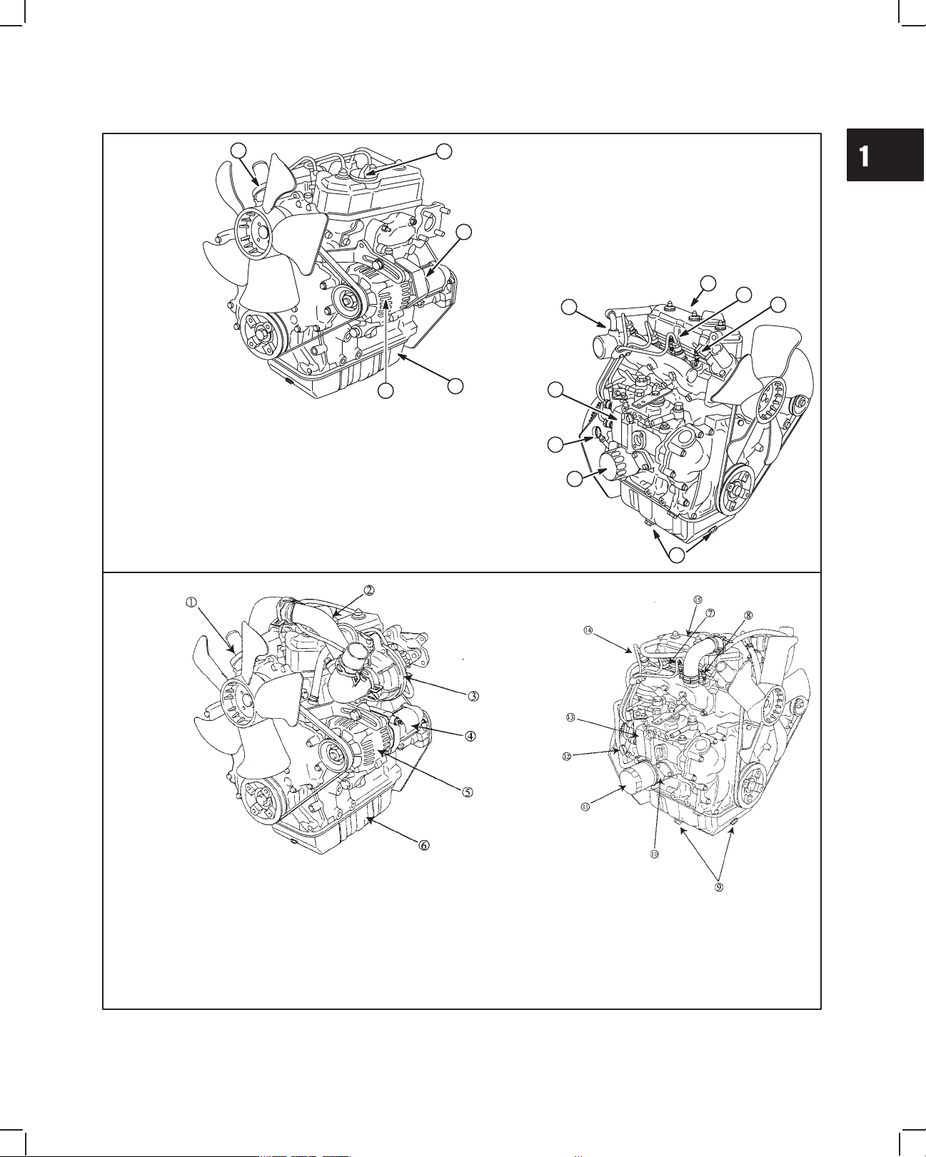
ENGINE VIEWS
1
GENERAL INFORMATION
Diesel
1. Thermostat
2. Oil filler cap
3. Electric starter
4. Oil pan
5. Alternator
1
5
2
3
13
6
12
4
11
7
6. Injector nozzle
7. Glow plug
8. Oil drains
9. Oil filter
10
10. Dipstick
11. Injector pump
9
12. Engine Date code
xxxxxxxx
13. Engine Model & Type number
xxxxxx xxxx-xx
8
Turbo-charged
Diesel
1. Thermostat
2. Oil filler cap
3. Turbocharger
4. Electric starter
5. Alternator
6. Oil pan
7. Injector nozzle
8. Glow plug
9. Oil drains
10. Oil cooler
(if equipped)
11. Oil filter
12. Dipstick
13. Injector pump
14. Engine Date code
xxxxxxxx
15. Engine Model & Type number
xxxxxx xxxx-xx
3
Page 5
1
GENERAL INFORMATION
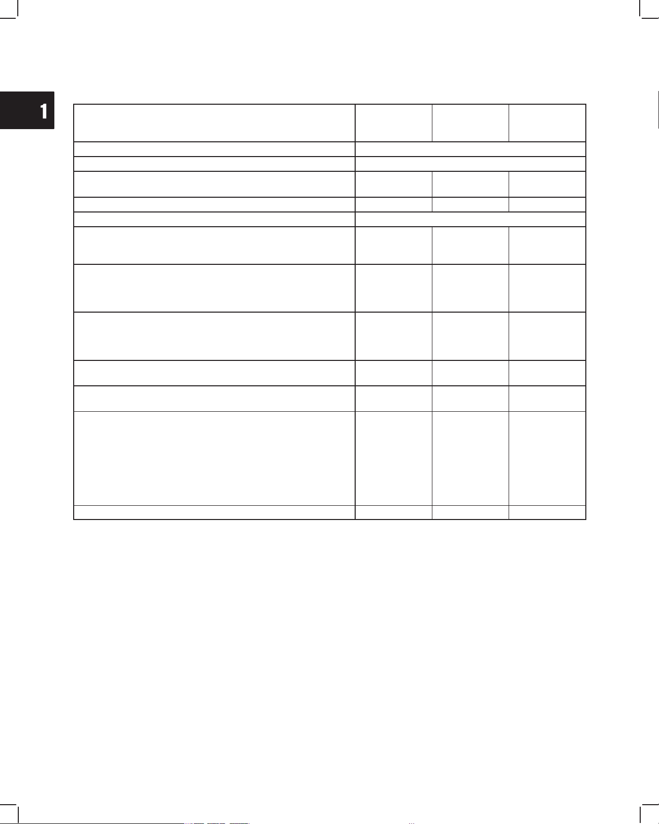
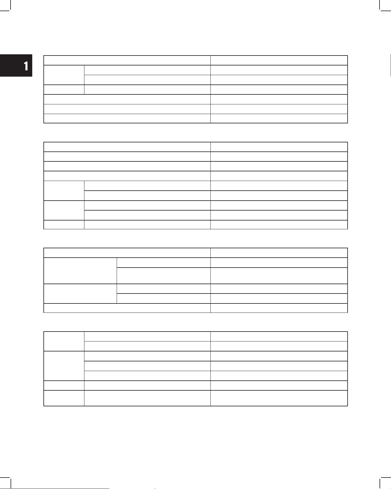
ENGINE SPECIFICATIONS
582447
Model 432447 522447
Type Diesel, 4-cycle, 3 cylinder, in-line, liquid cooled
Valve mechanism OHV, gear driven
Bore x stroke mm (in)
68 x 64
(2.680 x 2.520)
68 x 78
(2.680 x 3.070)
Piston displacement cc (cu in) 697 (42.5) 850 (52.0) 952 (58.1)
Firing order 1-2-3 (front, center, back)
Compression ratio 25.0:1 24.4:1
@58A447
@588447
72 x 78
(2.834 x 3.070)
24.0:1
@ 24.8:1
Compression pressure (normal)
Engine at operating temperature – (psi)
glow plugs removed
@
300 RPM Bar
33.0
(469)
32.0
(455)
34.0
(498)
@ 37
(526)
Compression pressure (minimum)
Engine at operating temperature – (psi)
glow plugs removed
@
300 RPM Bar
30.0
(425)
29.0
(412)
30.5
(433)
@ 27
(384)
Gross HP @ 3600 RPM 19.5 23.6
Gross Torque @ 2400 RPM 32.5 40.0
26.5
@ 28.0
44.1
@ 49.2
434.4 x 442.9
x 548.4
(17.1 x 17.44 x
21.59)
@ 434.4 x
447.5 x 559.0
Dimensions (L x W x H) mm (in)
441.8 x 440.4 x
523.9
(17.4 x 17.34 x
20.6)
434.4 x 442.9 x
548.4
(17.1 x 17.44 x
21.59)
(17.1 x 17.62 x
22.01)
Dry weight kg (lbs) 76 (168) 78 (172) 89 (196)
4
Page 6

1
Cylinder
Valve
Val
g
I
23
Specifications
Valve timing
Exh
23
Valve cl
ld)
Pi
Crankshaft &
GENERAL INFORMATION
Cylinder
Head
ve
Cylinder
Block &
Camshaft
Connecting
Rod & Piston
Crankshaft &
Crankshaft
Bearing
Type Single piece casting
Material Cast Iron
Combustion Chamber Swirl Type
seat angle
Valve timin
earance (co
Intake
Exhaust
ntake
aust
Opens 10° BTDC
Closes 45° ABDC
Opens 45° BBDC
Closes 10° ATDC
Intake mm (in) 0.20 (.008 in)
Exhaust mm (in) 0.20 (.008 in)
45°
45°
5°
5°
Cylinder block Mono-block, three cylinder, cast iron
Camshaft Carbon steel
Connecting rod Carbon steel
Piston Pin Bearing Machined – Piston pin, slip fit
Crankpin
Bearing
Material aluminum alloy – replaceable insert
Piston Heat resistant aluminum alloy
ston ring
Compression ring Two, chrome plated
Oil ring One, combination type, chrome plated
Crankshaft One piece cast iron
Crankshaft main
bearing
Material Replaceable insert – aluminum alloy
°
°
5
Page 7
1
Syst
GENERAL INFORMATION
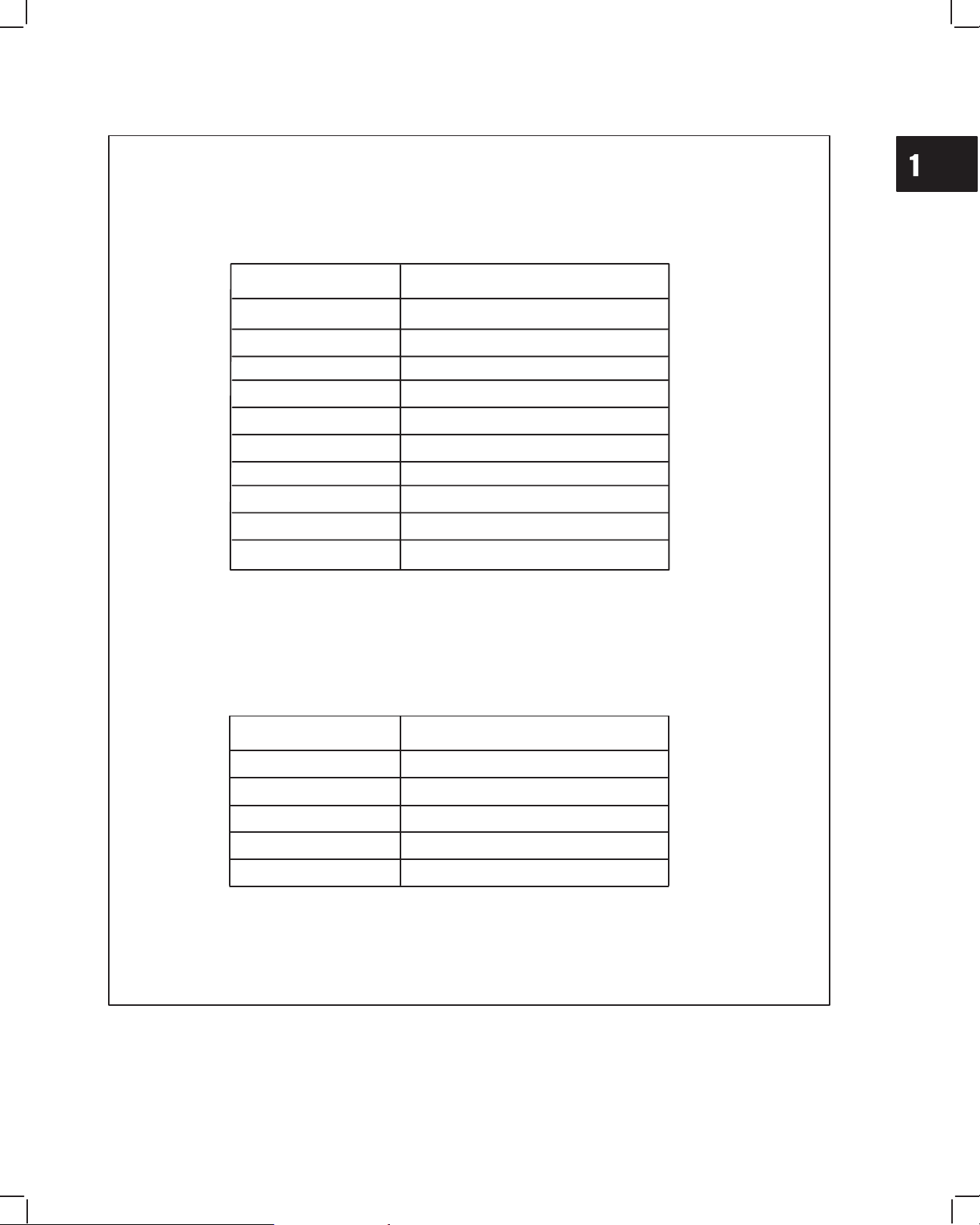
LUBRICATING SYSTEM
Lubricating Method Pressure lube
Oil Pump
Oil Filter Type Full flow, paper
Oil Capacity 3.3 ltr (3.5 qt)
Oil Pump Relief Valve Opening Pressure 4.6 Bar (65 psi)
Lubrication Oil API SE/CD class or higher
Type Trochoid
Drive Gear drive
COOLING SYSTEM
Cooling Method Liquid cooled, forced circulation
Coolant Capacity (engine only) Approximately 1.8 ltr (1.9 qt)
Cooling System Pressure 1.0-0.75 Bar (15-11 psi)
Pressure Cap Capacity 0.9 Bar (13 psi)
Water Pump
Thermostat
Cooling Fan Drive V-belt
Type Centrifugal
Drive V-belt
Type Wax pellet with bypass
Specification 82° C (180° F)
FUEL SYSTEM
Fuel Requirements Diesel fuel (Cetane number 40 or higher)
Type Bosch VE (distributor type)
Injector Pump
Injector Nozzle
Idle Speed RPM See Table 3, Page 7
Injector Timing (Plunger stroke)
#1 Cyl. TDC
Nozzle Type Throttle type
Injector pressure Bar (psi) 140 (1,991)
See Tables 1 & 2, Page 6
ELECTRICAL SYSTEM
Battery
Charging
em
Glow Plug Voltage/Current V/A 11 Volts / 9.5 Amps
Starter Voltage/Kilowatt V/K
Voltage 12V (negative ground)
Capacity 24 AH (28 AH cold)
Alternator 28 Volt AC output – Minimum
Regulator/rectifier 14 Amp DC output with charge indicator circuit
Alternator {Optional} 40 Amp DC output – Internally regulated
Reduction gear type – 12 Volts / 1.0 kw
{12 Volts / 1.2 kw, optional}
6
Page 8
1
TABLE 1
Injection Pump Timing
Engine Date Code Before 99010100
Model/Type No. Timing Specification
GENERAL INFORMATION
432447-0150-E2
522447-0105-E2
522447-0106-E2
522447-0107-E2
522447-0108-E2
522447-0109-E2
582447-0105-E2
582447-0125-E2
582447-0130-E2
582447-0131-E2
0.93 ± .03 mm (.0365” ± .001”)
0.93 ± .03 mm (.0365” ± .001”)
0.93 ± .03 mm (.0365” ± .001”)
0.93 ± .03 mm (.0365” ± .001”)
0.93 ± .03 mm (.0365” ± .001”)
0.93 ± .03 mm (.0365” ± .001”)
0.93 ± .03 mm (.0365” ± .001”)
0.81 ± .03 mm (.032” ± .001”)
0.93 ± .03 mm (.0365” ± .001”)
0.81 ± .03 mm (.032” ± .001”)
TABLE 2
Injection Pump Timing
Engine Date Code After 98123100
Model Series Timing Specification
432447 – All
522447 – All
582447 – All
58A447 – All
588447
0.90 ± .03 mm (.035” ± .001”)
0.90 ± .03 mm (.035” ± .001”)
0.81 ± .03 mm (.032” ± .001”)
0.90 ± .03 mm (.035” ± .001”)
7
Page 9
1
22100 87802
9U1
22100-8780
8U1
22100-87809
8U2
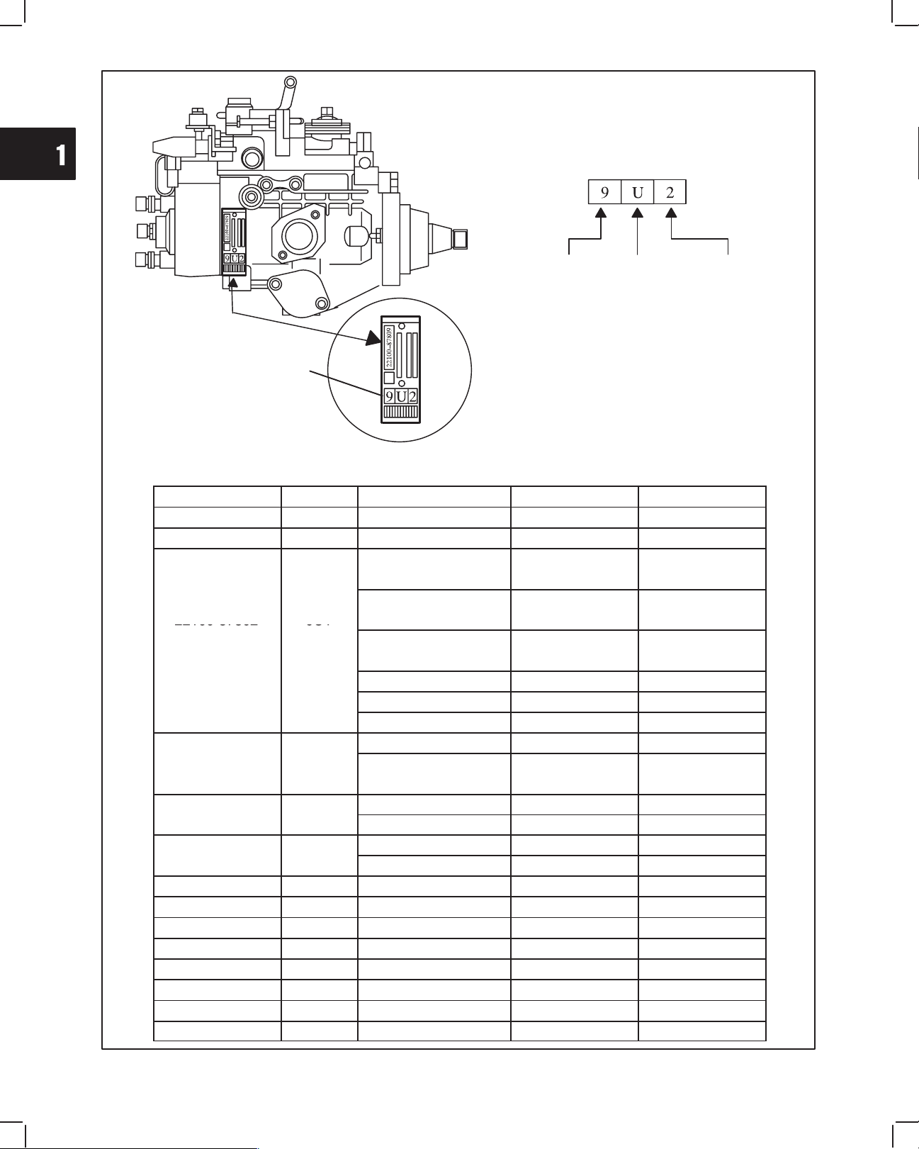
INJECTOR PUMP IDENTIFICATION
IDENTIFICATION CODE
NAME
PLATE
IDENTIFICATION
CODE
7 : 700 cc
8 : 850 cc
9 : 950 cc
DESTINATION
U : USA
J : Japan
X : Except for
USA
SERIAL
NUMBER
TABLE 3
Engine Speed Specification Chart
Pump Mfg. Part No. ID Code Model & Type No. Idle Speed (rpm) Top No Load (rpm)
22100-87801 7U1 432447-0105-E2
22100-8713 7U2 432447-0205-E2
582447-0105-E2
582447-0205-E2
582447-0130-E2
22100-87802 9U1
582447-0230-E2
582447-0219-E2
582447-0222–E2
582447-0221-E2
582447-0225-E2
582447-0232-E2
582447-0125-E2
22100-87806 9U2
582447-0131-E2
582447-0231-E2
7
522447-0105-E2
522447-0108-E2
522447-0106-E2
522447-0109-E2
22100-87810 8U3 522447-0107-E2
22100-87815 8U4 522447-0107-E2
22100-87817 8U5 522447–0107–E2
22100-87811 9U4 58A447–0205–E2
22100-87818 9U5 588447–0205–E2
588447–0216–E2
588447–0230–E2
588447–0225–E2
1200±50 3850±50
1200±50 3850±50
1200±50 3850±50
1200±50 3300±50
1600±50 3600±50
1750±50 3600±50
1050±50 3850±50
1200±50 3400±50
1850±50 3420±50
1700±50 3600±50
1200±50 3850±50
1600±50 3350±50
1850±50 3420±50
1850±50 3420±50
1525±50 2775±50
1540±50 2790±50
1540±50 2790±50
1200±50 3850±50
1200±50 3850±50
1800±50 3600±50
1600±50 3600±50
1050±50 3850±50
8
Page 10
1
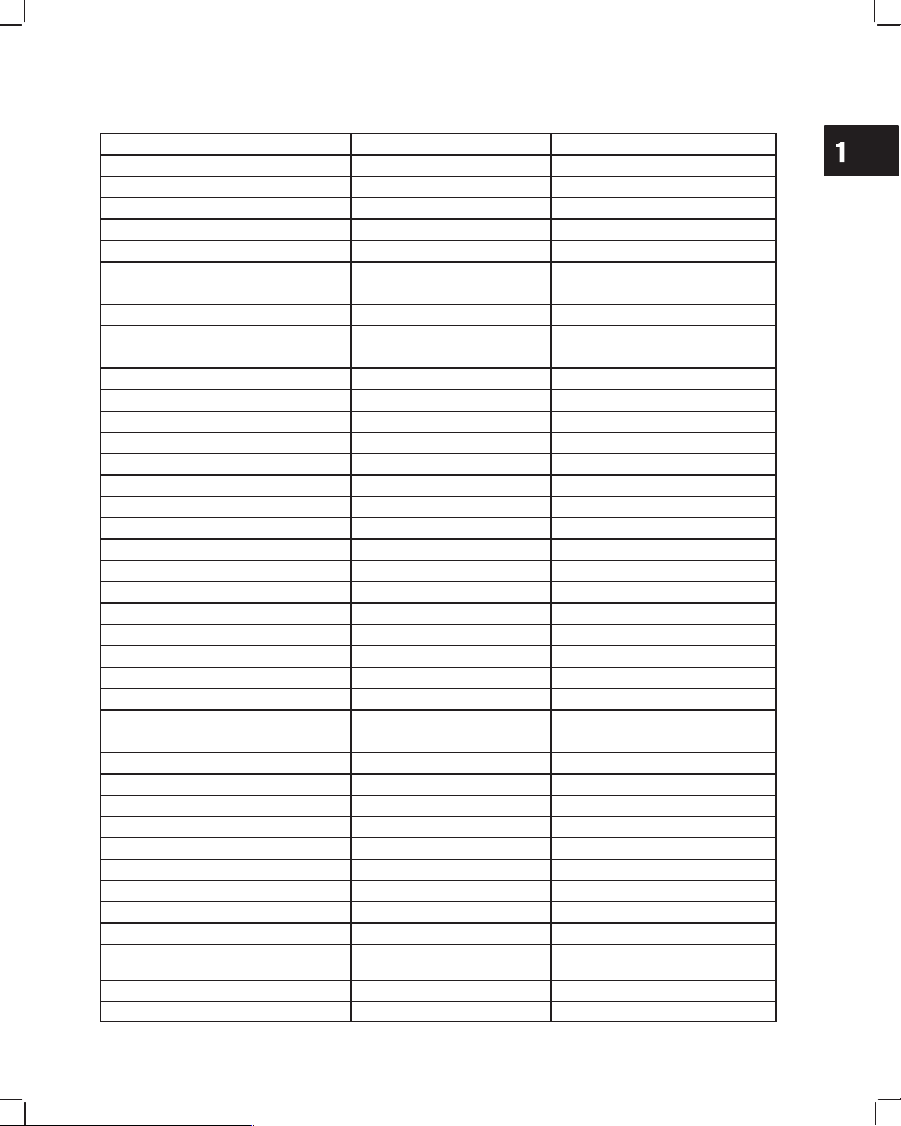
GENERAL INFORMATION
Description Wrench/Socket Size Torque
Alternator Adjust. Bracket 12 mm 19.0 Nm (170 in. lbs.)
Alternator – 14 Amp (to bracket) 12 mm 19.0 Nm (170 in. lbs.)
Alternator – 40 Amp (to bracket) 12 mm 61.0 Nm (45 ft. lbs.)
Alternator Bracket (to block) 12 mm 19.0 Nm (170 in. lbs.)
Camshaft Gear 17 mm 41.0 Nm (30 ft. lbs.)
Camshaft Retainer 10 mm 8.0 Nm (70 in. lbs.)
Conn. Rod Nuts 12 mm 36.0 Nm (320 in. lbs.)
Crankshaft Pulley 19 mm 88.0 Nm (65 ft. lbs.)
Cyl. Head Bolts (8 mm dia.) 12 mm 34.0 Nm (25 ft. lbs.)
Cyl. Head Bolts (9 mm dia.) 13 mm 43.0 Nm (32 ft. lbs.)
Cyl. Head Bolts (10 mm dia.) 14 mm 68.0 Nm (50 ft. lbs.)
Exhaust Manifold 12 mm 19.0 Nm (170 in. lbs.)
Fan Pulley 10 mm 7.0 Nm (60 in. lbs.)
Flywheel 14 mm 47.0 Nm (35 ft. lbs.)
Fuel Delivery Lines 17 mm 25.0 Nm (220 in. lbs.)
Fuel Return Line 17 mm 27.0 Nm (20 ft. lbs.)
Glow Plug 12 mm Deep 17.0 Nm (150 in. lbs.)
Idler Gear 12 mm 25.0 Nm (220 in. lbs.)
Injector Pump (mounting) 12 mm 19.0 Nm (170 in. lbs.)
Injector Pump Drive Gear 19 mm 61.0 Nm (45 ft. lbs.)
Injector Pump Bracket 12 mm 19.0 Nm (170 in. lbs.)
Injector Nozzle 21 mm Deep 61.0 Nm (45 ft. lbs.)
Injector Pump Distributor Bolt 14 mm 17.0 Nm (150 in. lbs.)
Intake Manifold 10 mm 8.0 Nm (70 in. lbs.)
Main Bearing Screws 14 mm 58.0 Nm (43 ft. lbs.)
Oil Drain Plug 14 mm 25.0 Nm (220 in. lbs.)
Oil Pan 10 mm 8.0 Nm (70 in. lbs.)
Oil Pressure Relief Valve 19 mm 34.0 Nm (25 ft. lbs.)
Oil Pump Gear 12 mm 19.0 Nm (170 in. lbs.)
Oil Pump Pickup 10 mm 8.0 Nm (70 in. lbs.)
Rear Seal Support 10 mm 6.0 Nm (50 in. lbs.)
Rocker Arm Assy. 12 mm Deep 19.0 Nm (170 in. lbs.)
Rocker Arm Adjustment 10 mm 11.0 Nm (95 in. lbs.)
Starter 14 mm 40.0 Nm (30 ft. lbs.)
Starter Bracket 14 mm 34.0 Nm (25 ft. lbs.)
Starter Solenoid Phillips 9.0 Nm (80 in. lbs.)
Starter Motor Thru Bolts 10 mm 9.0 Nm (80 in. lbs.)
Timing Gear Case 10 mm 8.0 Nm (70 in. lbs.)
Timing Gear Cover
(3 different lengths)
Valve Cover 10 mm 6.0 Nm (50 in. lbs.)
Water Pump 12 mm 19.0 Nm (170 in. lbs.)
10 mm 8.0 Nm (70 in. lbs.)
9
Page 11

1
GENERAL INFORMATION
BRIGGS & STRATTON DAIHATSU NUMERICAL NUMBER SYSTEM
All Briggs & Stratton Daihatsu engines have a unique numerical designation system. Each engine is identified by a
Model, Type and Code/Serial number. Example: Model Type Code/Serial
432447 0125 01 020521145
This chart explains the numerical model designation system. It is possible to determine most of the important mechanical features of the engine by merely knowing the model number. Here is how it works.
CUBIC INCH
DISPLACEMENT
ă6
ă8
ă9
10
11
12
13
16
17
18
19
22
23
24
25
26
28
29
30
32
35
38
40
42
43
44
46
52
58
FIRST DIGIT
AFTER DISPLACEMENT
BASIC
DESIGN SERIES
0 - Gas-Mechanical
1 - Natural Gas-Mechanical
2 - Diesel-Mechanical
3 - Gas-Electronic
4 - Natural Gas-Electronic
5 - Diesel-Electronic
6
7
8 - Diesel - Turbo
9
A - Diesel Turbo
B to Z
SECOND DIGIT
AFTER DISPLACEMENT
CRANKSHAFT,
CARBURETOR,
GOVERNOR
0 - Horizontal Shaft
Diesel Electronic or
Mechanical Governor
1 - Horizontal Shaft
VacuĆJet Carburetor
Pneumatic Governor
2 - Horizontal Shaft
PulsaĆJet Carburetor
Pneumatic or Mechanical
Governor
3 - Horizontal Shaft
FloĆJet Carburetor
Pneumatic Governor
4 - Horizontal Shaft
FloĆJet Carburetor
Electronic or
Mechanical Governor
5 - Vertical Shaft
VacuĆJet Carburetor
Pneumatic or Mechanical
Governor
6 - Vertical Shaft
7 - Vertical Shaft
FloĆJet Carburetor
Pneumatic or Mechanical
Governor
8 - Vertical Shaft
FloĆJet Carburetor
Mechanical Governor
9 - Vertical Shaft
PulsaĆJet Carburetor
Pneumatic or Mechanical
Governor
THIRD DIGIT
AFTER DISPLACEMENT
PTO BEARING,
REDUCTION GEAR,
AUXILIARY DRIVE,
LUBRICATION TYPE OF STARTER
0 - Plain Bearing/DU
NonĆFlange Mount
1 - Plain Bearing
Flange Mounting
2 - Sleeve Bearing
Flange Mounting
Splash Lube
3 - Ball Bearing
Flange Mounting
Splash Lube
4 - Flange Mounting
Pressure Lubrication on
Horizontal Shaft
5 - Plain Bearing
Gear Reduction
(6 to 1) CW Rotation
Flange Mounting
6 - Plain Bearing
Gear Reduction
(6 to 1) CCW Rotation
7 - Plain Bearing
Pressure Lubrication on
Vertical Shaft
8 - Plain Bearing
Auxiliary Drive (PTO)
Perpendicular to Crankshaft
9 - Plain Bearing
Auxiliary Drive
Parallel to Crankshaft
FOURTH DIGIT
AFTER DISPLACEMENT
0 - Without Starter
1 - Rope Starter
2 - Rewind Starter
3 - Electric Starter Only
120 Volt Gear Drive
4 - Electric Starter/Generator
12 Volt Belt Drive
5 - Electric Starter Only
12 Volt Gear Drive
6 - Alternator Only
7 - Electric Starter
12 Volt Gear Drive
With Alternator
8 - Vertical Pull Starter or
Side Pull Starter
The type number identifies certain unique features such as the crankshaft or governor spring used on an engine.
The code/serial number identifies the assembly date of the engine and serial number. In some instances it is neces-
sary to know the code/serial number as well as the model and type number when performing adjustments, repairs or
ordering replacement parts for an engine. Here is how it works.
Example: 990521150
A. The first two digits, 02, indicate the calendar
year, 2002.
B. The second two digits, 05, indicate the calen-
dar month, May.
10
C. The third two digits, 21, indicate the calendar
month day.
D. The last three digits, 145, indicate the serial
number.
Page 12
1
Lubrication
system
GENERAL INFORMATION
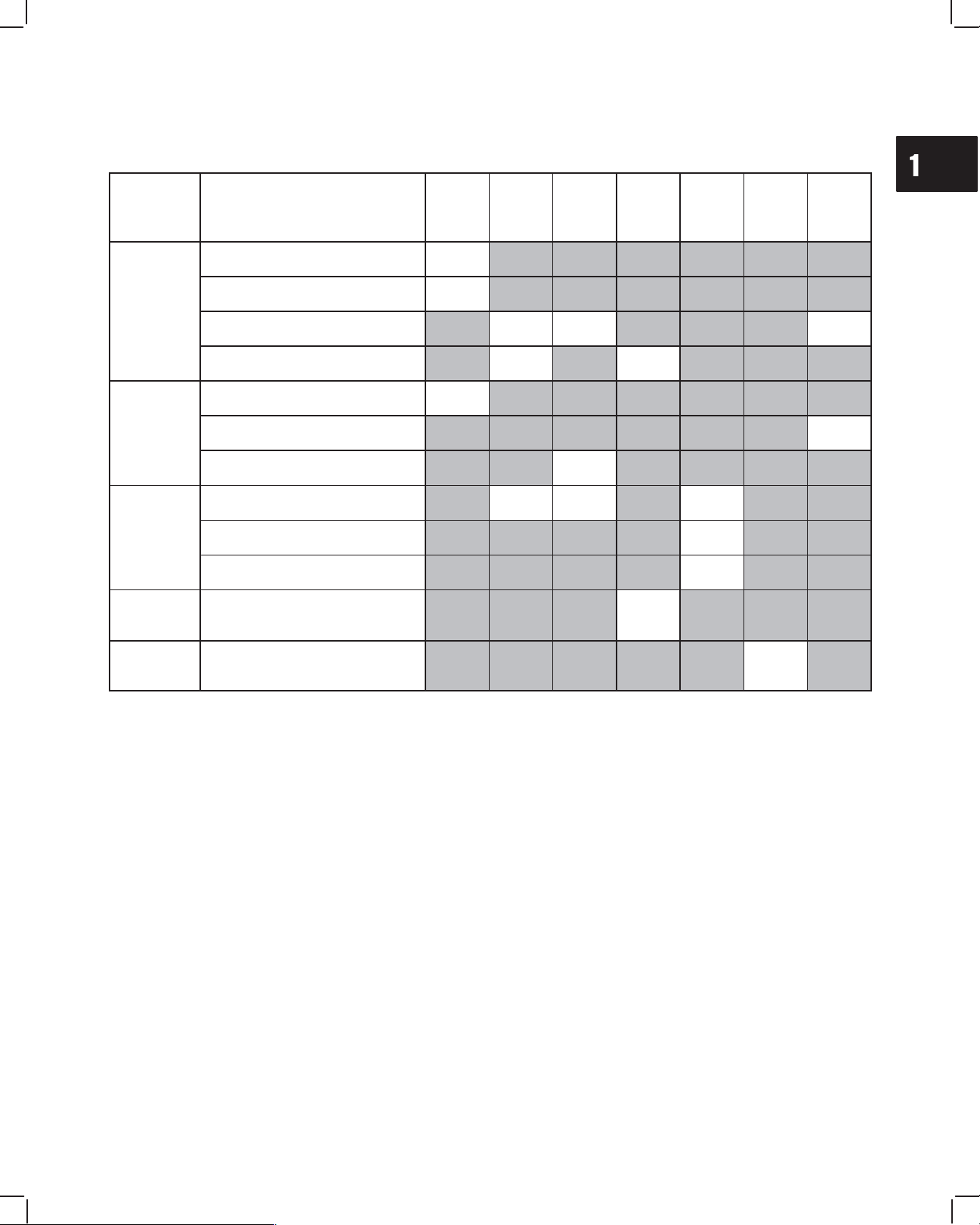
MAINTENANCE SCHEDULE
More frequent service is required when operating in adverse conditions (note 4 below).
System Maintenance Operation Daily
Lubrication
system
Cooling
system
Engine
Electrical
system
Check oil level
Check for oil leaks
Change oil
Change oil filter
Check coolant
Change coolant
Check fan belt
Service air cleaner
Check cylinder head bolt torque
Check valve clearance
Check battery electrolyte
D
D
D
Every
50
hours
D1 D2 D5
D1 D2
D1 D2, 4 D3, 4
Every
100
hours
D
Every
200
hours
D
Every
600
hours
D
D
Every
800
hours
Yearly
D
Fuel
system
1 Perform first maintenance operation after 50 hours.
2 Then perform maintenance operation at this interval.
3 Replace after ever 600 hours of operation.
4 Service more often when operating under heavy load or in high temperatures.
5 Perform maintenance annually if operated less than 100 hours.
6 Follow manufacturer’s maintenance schedule if non-B&SD approved part is used.
Change fuel filter element
D6
11
Page 13
2
BRIGGS & STRATTON DAIHATSU 3 CYLINDER
LIQUID-COOLED DIESEL ENGINE REPAIR MANUAL (MS-1055)
Section 2
Cylinder Head and Valves
Section Contents
Page
REMOVE CYLINDER HEAD 2. . . . . . . . . . . . . . . . . . . . . . . . . . . . . . . . . . . . . . . . . . . . . . . . . . . . . . . . . . . . . .
DISASSEMBLE CYLINDER HEAD 4. . . . . . . . . . . . . . . . . . . . . . . . . . . . . . . . . . . . . . . . . . . . . . . . . . . . . . . .
INSPECT AND REPAIR
Cylinder Head 5. . . . . . . . . . . . . . . . . . . . . . . . . . . . . . . . . . . . . . . . . . . . . . . . . . . . . . . . . . . . . . . . . . . . . .
Valve Guides 6. . . . . . . . . . . . . . . . . . . . . . . . . . . . . . . . . . . . . . . . . . . . . . . . . . . . . . . . . . . . . . . . . . . . . . .
Valves 7. . . . . . . . . . . . . . . . . . . . . . . . . . . . . . . . . . . . . . . . . . . . . . . . . . . . . . . . . . . . . . . . . . . . . . . . . . . . .
DISASSEMBLE ROCKER ARM SHAFT 8. . . . . . . . . . . . . . . . . . . . . . . . . . . . . . . . . . . . . . . . . . . . . . . . . . . .
ASSEMBLE ROCKER ARM SHAFT 9. . . . . . . . . . . . . . . . . . . . . . . . . . . . . . . . . . . . . . . . . . . . . . . . . . . . . . .
ASSEMBLE CYLINDER HEAD 10. . . . . . . . . . . . . . . . . . . . . . . . . . . . . . . . . . . . . . . . . . . . . . . . . . . . . . . . . . .
INSTALL CYLINDER HEAD 11. . . . . . . . . . . . . . . . . . . . . . . . . . . . . . . . . . . . . . . . . . . . . . . . . . . . . . . . . . . . .
ADJUST VALVES 14. . . . . . . . . . . . . . . . . . . . . . . . . . . . . . . . . . . . . . . . . . . . . . . . . . . . . . . . . . . . . . . . . . . . . .
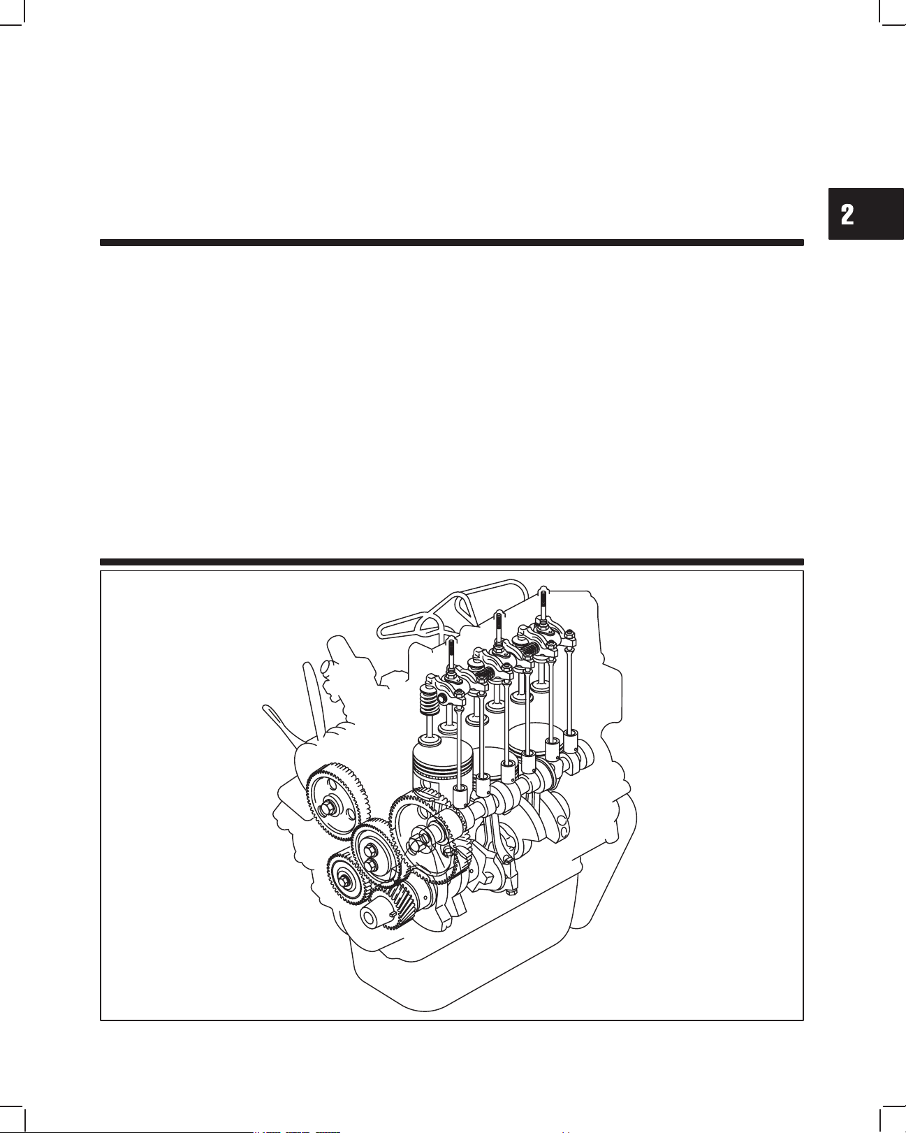
Overhead Valve Train
1MAY 2002
Page 14
2
CYLINDER HEAD AND VALVES
REMOVE CYLINDER HEAD
ALWAYS disconnect fuel shut off solenoid wire
from injection pump before checking compression, to prevent accidental starting.
Drain cooling system and disconnect radiator hoses.
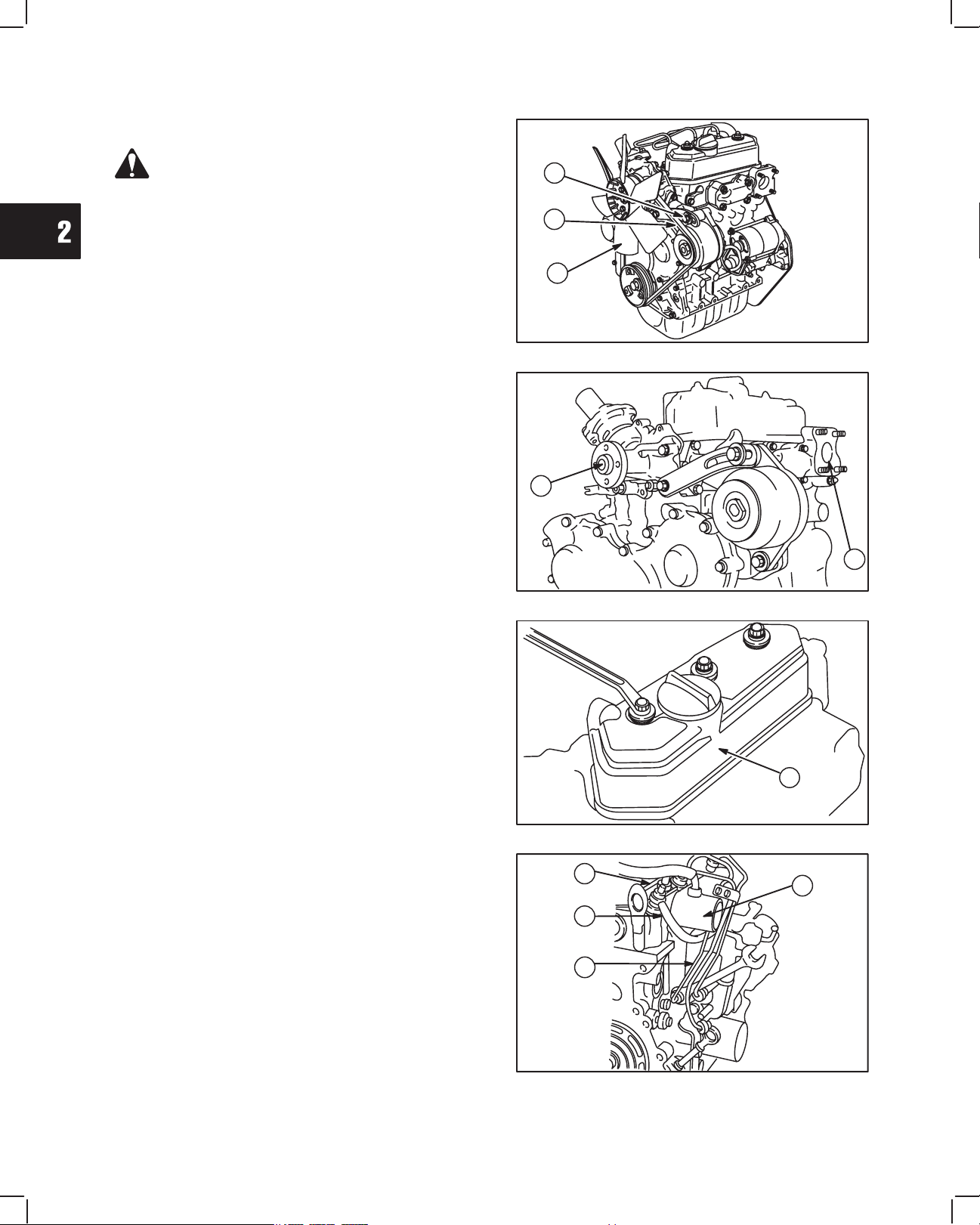
1. Remove the following parts from engine,
Fig. 1-Fig. 5:
a. Alternator adjusting bracket screw
b. V-belt
c. Fan (if equipped)
Fig. 2:
d. Water pump
e. Exhaust manifold
NOTE: Remove exhaust system before removing
exhaust manifold.
A
B
C
Fig. 1 – Remove V-belt And Fan
D
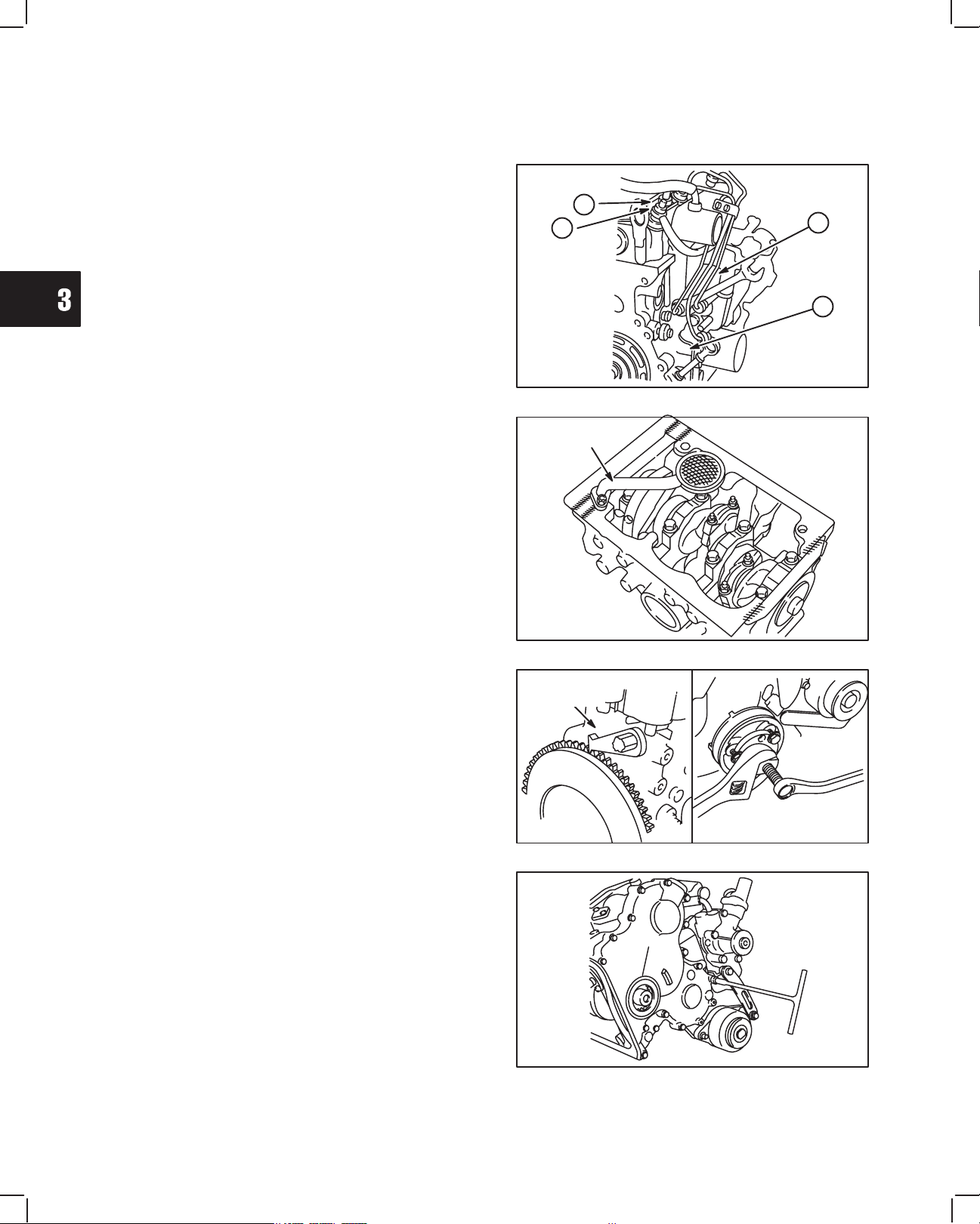
Fig. 3:
f. Valve cover
Discard rubber seal.
NOTE: Clean areas around fuel lines and injec-
tors to prevent dirt entry.
Fig. 4:
g. Fuel delivery lines
h. Fuel return line
i. Glow plug wiring
j. Breather tube and intake manifold
Fig. 2 – Remove Water Pump And Exhaust Manifold
F
Fig. 3 – Remove Valve Cover
I
H
G
J
E
Fig. 4 – Remove Fuel Lines
2
Page 15
2
CYLINDER HEAD AND VALVES
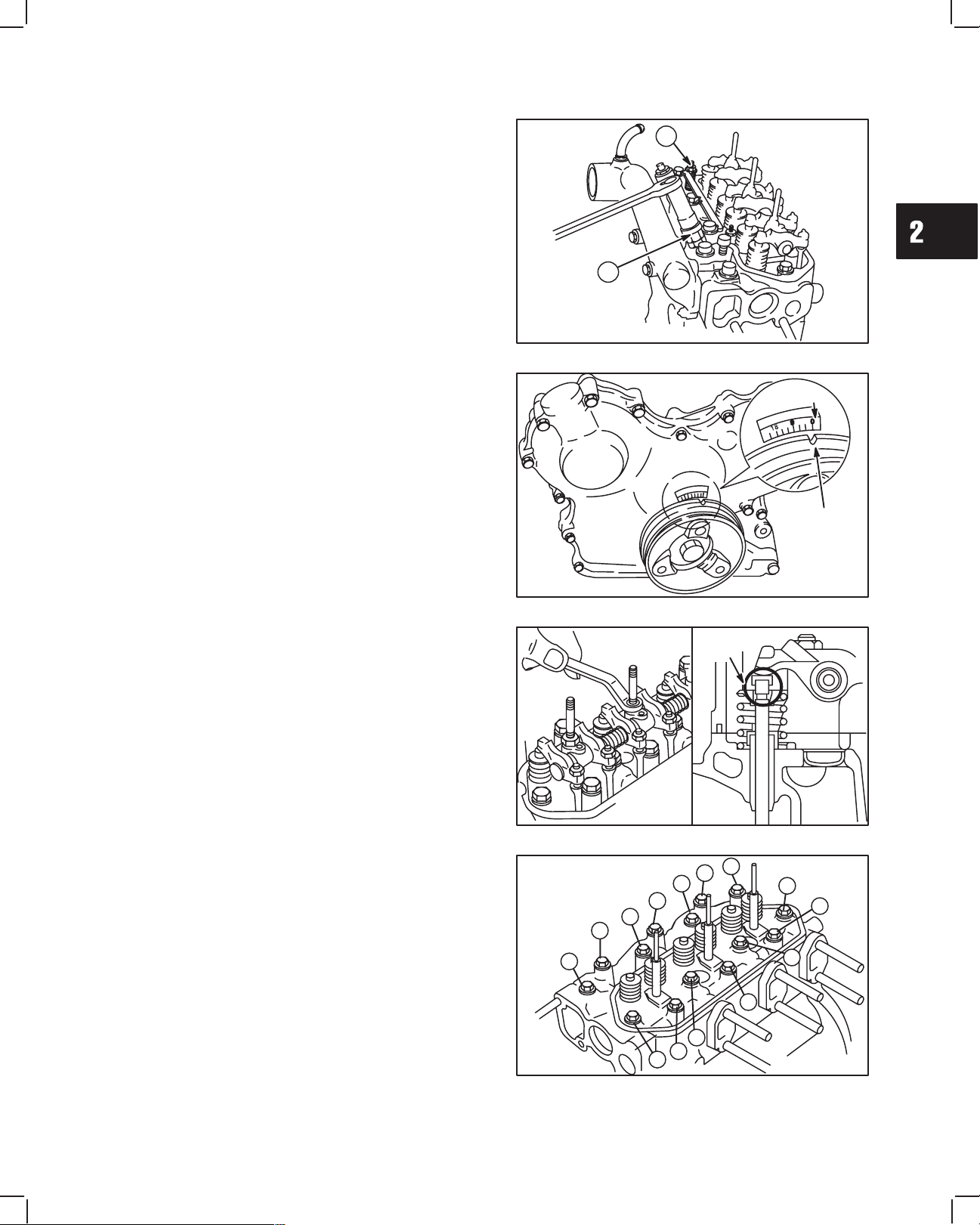
Fig. 5:
k. Fuel injector nozzles
l. Glow plugs
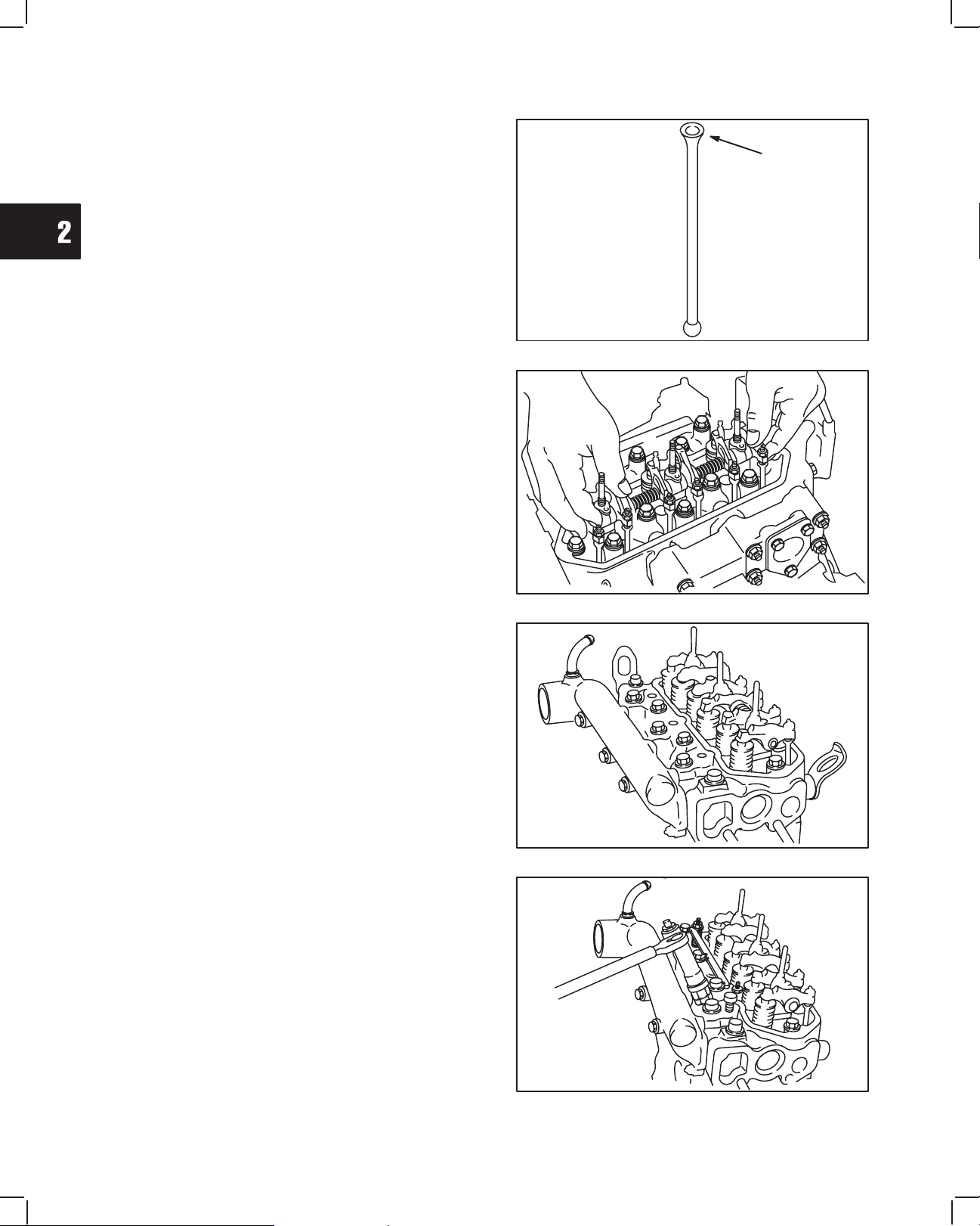
2. Set No. 1 piston at TDC, Fig. 6:
a. Rotate crankshaft pulley until timing mark on
pulley is aligned with reference point on timing
cover.
b. If intake and exhaust valves have clearance,
No. 1 piston is at TDC – compression stroke.
c. If intake and exhaust valves do not have
clearance, turn crankshaft pulley one
complete revolution. Valves will then have
clearance.
L
K
Fig. 5 – Remove Glow Plugs And Injectors
REFERENCE
POINT
TIMING
MARK
3. Remove rocker arm assembly and push rods,
Fig. 7.
a. Remove valve stem caps.
NOTE: Mark push rods so that they may be
reassembled in their original position.
4. Remove cylinder head assembly, Fig. 8.
a. Loosen cylinder head bolts in the order shown.
NOTE: Current style head bolts are 9 mm diame-
ter. Early style head bolts are 8 mm
diameter. Torque specifications are different.
Fig. 6 – Set Cylinder No. 1 At TDC
VALV E
STEM
CAP
Fig. 7 – Remove Rocker Arm Assembly And Push Rods
2
6
10
13
11
7
3
9
5
1
4
8
12
14
Fig. 8 – Loosen Cylinder Head Bolts
3
Page 16
CYLINDER HEAD AND VALVES
2
3
4
5
6
9
10
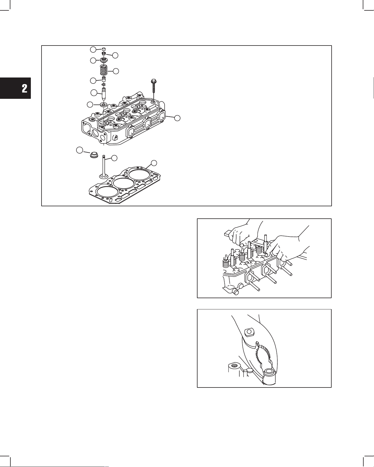
DISASSEMBLE CYLINDER HEAD
1. Cylinder Head Assembly
8
1
2. Cylinder Head Gasket
3. Valve Stem Cap
4. Valve Spring Retainer Locks
5. Valve Spring Retainer
6. Valve Spring
11
7
2
7. Valve
8. Valve Spring Seat
9. Valve Stem Seal
10. Valve Guide
11. Combustion Chamber
Fig. 9 – Cylinder Head Components
Remove valves, Fig. 10.
1. Use valve spring compressor, Tool #19417, to
compress valve springs. Remove the following
parts, Fig. 9:
a. Valve spring retainer locks – 4
b. Valve spring retainer – 5
c. Valve spring – 6
d. IN and EX valve – 7
e. Valve spring seats – 8
2. Remove and discard valve stem seals, Fig. 11.
Fig. 10 – Remove Valves
Fig. 11 – Remove Valve Stem Seal
4
Page 17
2
CYLINDER HEAD AND VALVES
INSPECT AND REPAIR
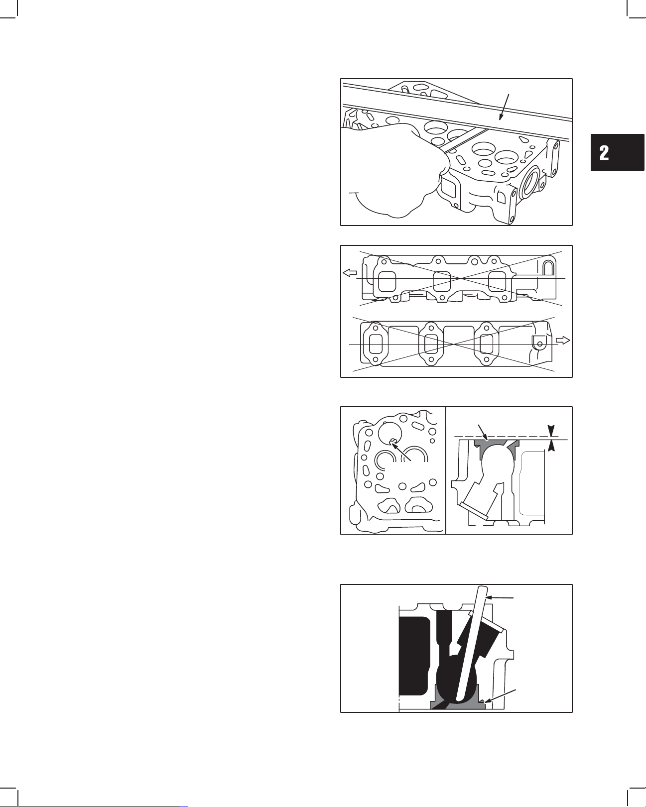
1. Check cylinder head mounting surfaces, Fig. 12
and Fig. 13.
Be sure all gasket material is removed from surfaces
before checking. Use a gasket scraper if necessary.
a. Inspect cylinder head for cracks or damage.
b. Use a straight edge and check cylinder head
lower surface for distortion.
Fig. 13:
c. Check intake and exhaust manifold mounting
surfaces.
If mounting surfaces are distorted more than 0.1 mm
(0.004 in.), the cylinder head must be replaced.
It is not recommended that cylinder head
mounting surfaces be resurfaced.
NOTE: Intake manifold and exhaust manifold
may be checked in the same manner. Use
same specifications as cylinder head.
CHECK COMBUSTION CHAMBER
Engine Model 522000: combustion chambers are
not replaceable.
Engine Models 432000 and 582000 with date code
after 990111007: combustion chambers are not
replaceable.
NOTE: Only Engine Models 432000 and 582000
with date code before 981225006 have
replaceable combustion chambers.
1. Check combustion chamber, Fig. 14.
a. Use a straight edge and feeler gauge.
If combustion chamber protrudes more than 0.05 mm
(.002 in.) above surface of cylinder head, it must be
replaced.
2. Remove combustion chamber, Fig. 15.
Insert a 10 mm brass rod through injector nozzle hole
and drive out combustion chamber.
NOTE: Do not damage threads in injector hole.
STRAIGHT
EDGE
Fig. 12 – Check Cylinder Head For Distortion
Fig. 13 – Check Cylinder Head For Distortion
COMBUSTION
CHAMBER
COMBUSTION
CHAMBER
Fig. 14 – Check Combustion Chamber
BRASS ROD
COMBUSTION
CHAMBER
Fig. 15 – Remove Combustion Chamber
5
Page 18
2
CYLINDER HEAD AND VALVES
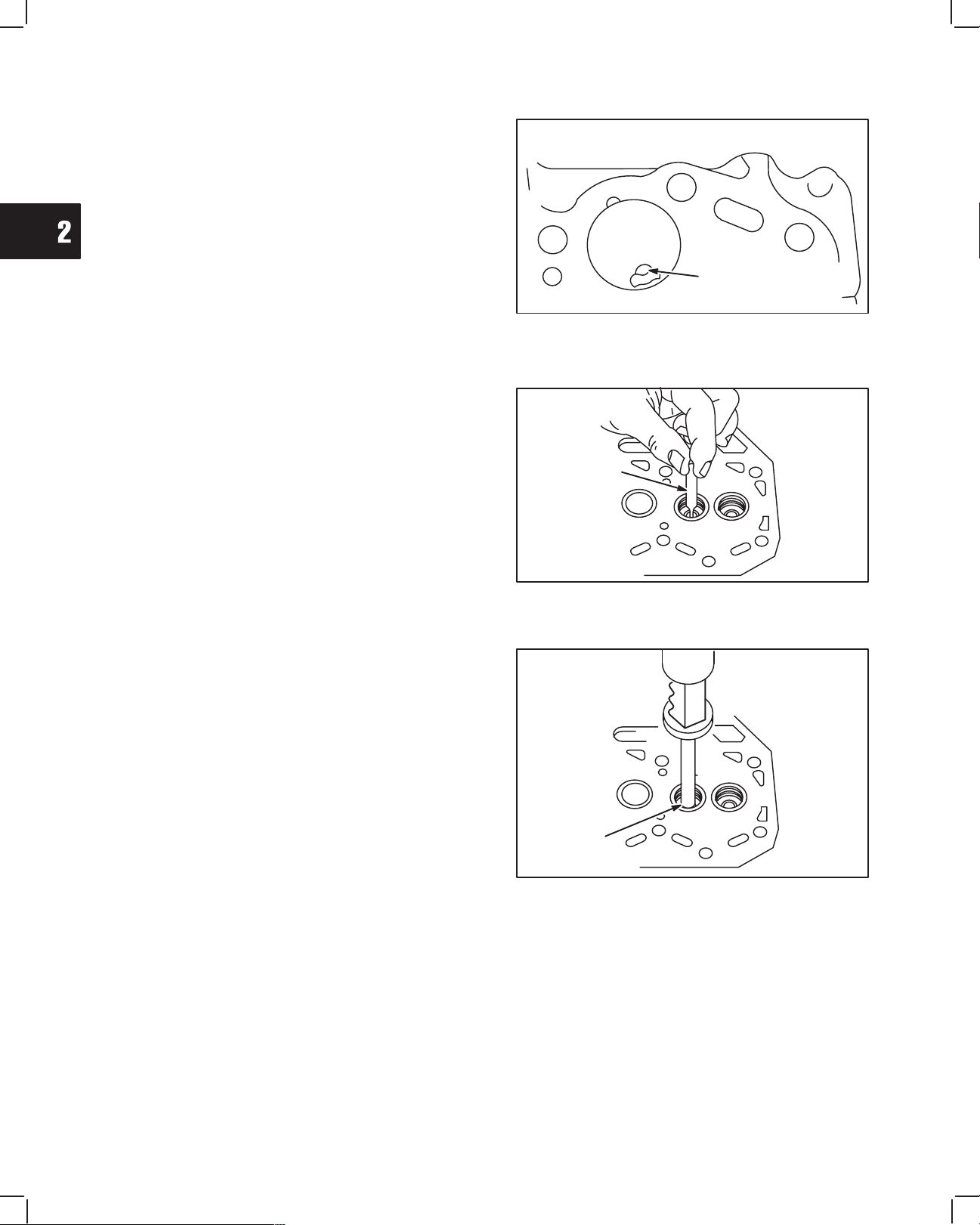
3. Install combustion chamber, Fig. 16.
Align locating projection on combustion chamber with
groove in cylinder head. Use a soft hammer and drive
in new combustion chamber until it bottoms.
CHECK AND REPAIR VALVE GUIDES
1. Check valve guide bushings for wear using reject
gauge, Tool #19382, Fig. 17.
COMBUSTION
CHAMBER
Fig. 16 – Install Combustion Chamber
Remove if damaged or if reject gauge enters valve
guide.
2. Remove valve guide bushing if required, Fig. 18.
a. Use bushing driver, Tool #19367, and press
out valve guide bushing from combustion
chamber side.
b. Check valve guide bushing OD. Then see
specifications below.
Std. Bushing OD: – 11.05 mm (.435 in.)
Replacement Bushing OD: – 11.08 mm (.4362 in.)
c. If bushing OD measurement indicates that a
replacement bushing has already been
installed, the cylinder head must be replaced.
REJECT
GAGE
Fig. 17 – Check Valve Guide Bushing
PRESSING OUT
GUIDE
Fig. 18 – Remove Valve Guide Bushing
6
Page 19
2
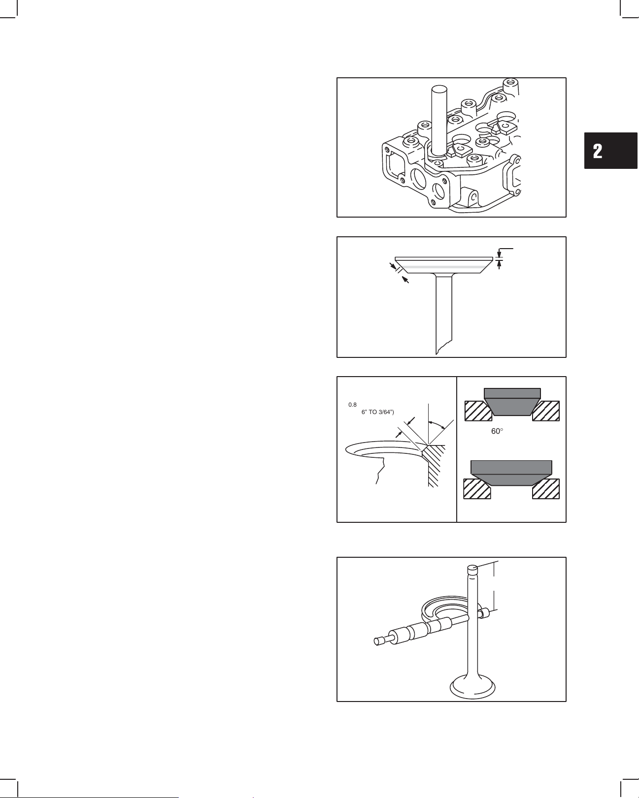
3. Using bushing driver, Tool #19416, press in new
valve guide bushing until tool bottoms on cylinder
head, Fig. 19.
CYLINDER HEAD AND VALVES
Fig. 19 – Installing Valve Guide Bushing
VALVES AND SEATS
1. Valve faces may be resurfaced to 45°. See Fig. 20
for dimensions for valves. Lap valves and seats
with valve lapping Tool, #19258 and valve lapping
compound, Tool #94150.
2. Valve seats may be reconditioned using valve seat
cutter, Tool #19446.
NOTE: Check valve guide bushings first. If valve
guides are worn, they must be replaced
before refacing valve seats
If valve seat is wider than dimension shown in Fig. 21,
a narrowing cutter should be used to ensure that
contact area of valve seat is centered on face of valve,
Fig. 20.
a. Use a 60° cutter to narrow seat from bottom
and a 30° cutter to narrow seat from top,
Fig. 21.
NOTE: If valve seat is loose or cracked, replace
cylinder head.
3. Measure valve stem diameter at specified
distance from end of valve, as shown in Fig. 22.
Replace IN if less than 5.927 mm (0.2333 in.).
Replace EX if less than 5.923 mm (0.2332 in.).
0.8 mm TO 1.2 mm
(1/16” TO 3/64”)
0.8 mm TO 1.2 mm
(1/16” TO 3/64”)
VALVE SEAT DIMENSIONS
Fig. 21 – Valve Seat Dimensions
SEATING AREA CENTERED
ON VALVE FACE
Fig. 20 – Valve Dimensions
45°
60° CUTTER
30° CUTTER
35 mm
(1.38”)
1.0 mm
(.040”)
MINIMUM
Fig. 22 – Measure Valve Stem Diameter
7
Page 20
2
CYLINDER HEAD AND VALVES
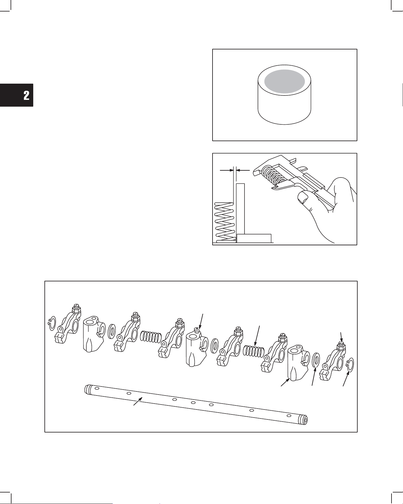
4. Inspect valve stem cap for wear, Fig. 23.
Replace if cap is worn recessed.
5. Check valve springs for squareness and free
length, Fig. 24.
Replace if out of square more than 1.0 mm
(.040 in.).
Replace if free length is less than 30.7 mm
(1.209 in.).
Fig. 23 – Check Valve Stem Cap
Fig. 24 – Check Valve Springs
DISASSEMBLE ROCKER ARM SHAFT
1. Remove snap rings from ends of rocker arm shaft. Remove set screw from center rocker arm support. Disassemble
rocker arm assembly. Note position of all components, Fig. 25.
SET
SCREW
ROCKER
ARM
SHAFT
(1)
SPRING
(2)
ROCKER
ARM SUPPORT
(3)
SPACER
(3)
ROCKER
ARM
(6)
SNAP
RING
(2)
Fig. 25 – Rocker Arm Components
8
Page 21
2
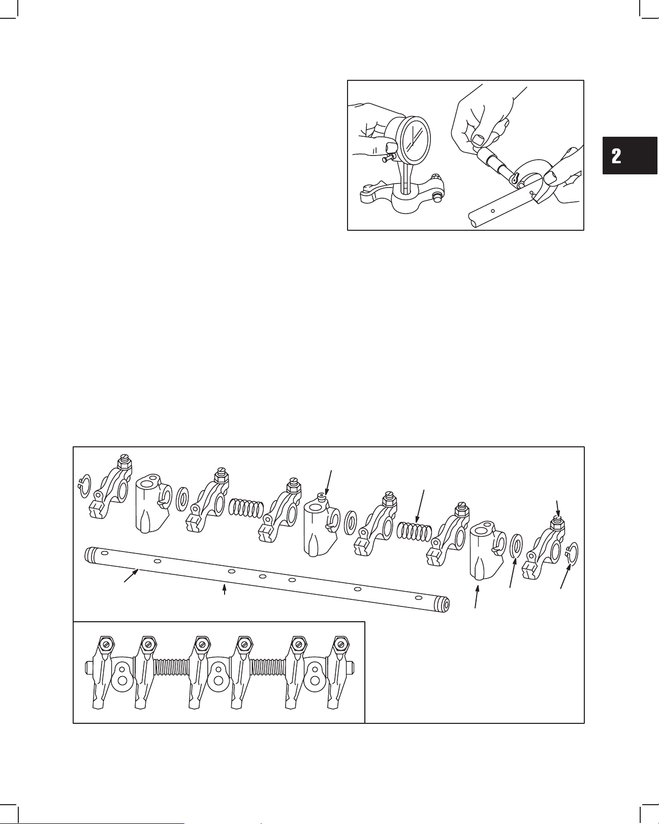
2. Check rocker arms and shaft, Fig. 26.
a. Check rocker arm-bearing surface.
Replace if greater than 10.03 mm (0.395 in.).
b. Check rocker arm shaft
Replace if less than 9.96 mm (0.392 in.).
c. Check rocker arm studs for stripped threads
and replace if required.
CYLINDER HEAD AND VALVES
Fig. 26 – Checking Rocker Arm And Shaft
ASSEMBLE ROCKER ARM SHAFT
1. Oil all components before assembling. Small grooves in rocker shaft next to oil holes must face down. Assemble
rocker arm components, noting order of assembly as shown in Fig. 27. Note position of three thrust washers.
Install set screw in center rocker arm shaft support.
SET
SCREW
ROCKER
ARM
SHAFT
OIL
GROOVES
DOWN
(1)
SPRING
(2)
ROCKER
ARM SUPPORT
(3)
THRUST
WASHER
(3)
ROCKER
ARM
(6)
SNAP
RING
(2)
Fig. 27 – Rocker Arm Components
9
Page 22
CYLINDER HEAD AND VALVES
2
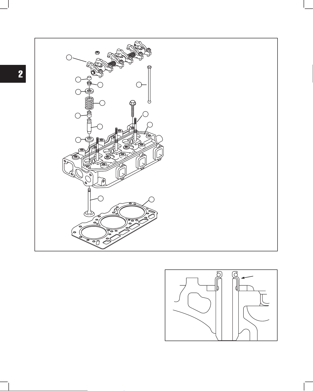
ASSEMBLE CYLINDER HEAD
12
3
4
5
6
9
10
8
1. Cylinder Head
2. Cylinder Head Gasket
3. Valve Stem Cap
4. Valve Spring Retainer Locks
5. Valve Spring Retainer
11
6. Valve Spring
7. Valve
8. Valve Spring Seat
9. Valve Stem Seal
13
10. Valve Guide
11. Push Rod
1
12. Rocker Arm Assembly
13. Rocker Arm Stud
NOTE: When replacing rocker arm studs,
torque to 20.0 Nm (180 in. lbs.).
7
Fig. 28 – Cylinder Head Components
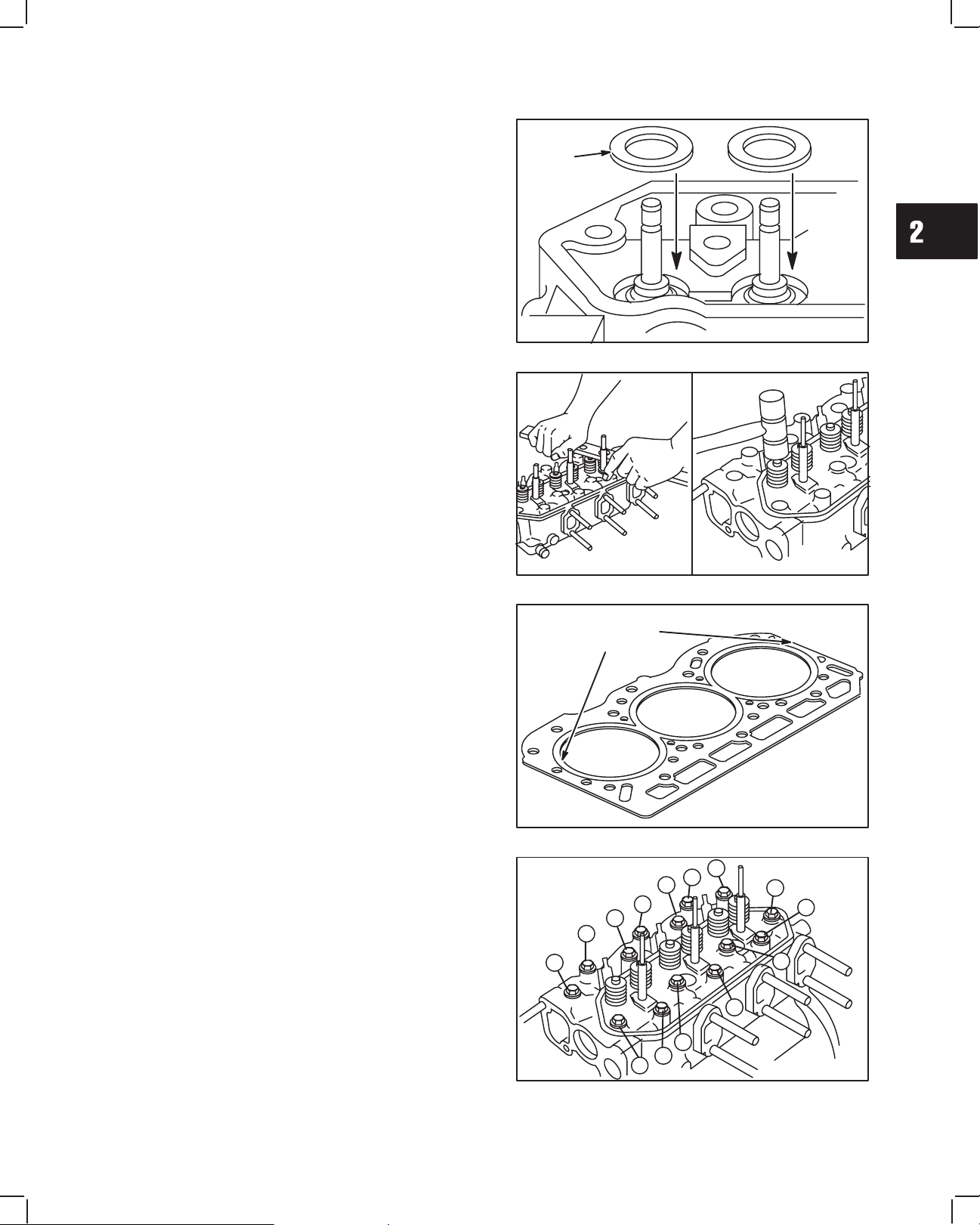
1. Install new valve stem seals, Fig. 29. Oil inner
surface and lip of seal before installing. Press seal
on to valve guide bushing until it bottoms.
2
VALVE STEM
SEAL
(CUTAWAY VIEW)
10
Fig. 29 – Install Valve Stem Seals
Page 23
2
2. Install valve spring seats, Fig. 30.
NOTE: Lightly coat valve stems with Valve Guide
Lubricant #93963 before installing valves.
3. Install valves.
4. Install valve springs with valve spring compressor,
Tool #19417, Fig. 31.
NOTE: After installing valve spring retainer locks,
tap valve spring retainer lightly with a soft
hammer to ensure locks are seated.
CYLINDER HEAD AND VALVES
VALV E
SPRING
SEATS
Fig. 30 – Install Valve Spring Seats And Valves
INSTALL CYLINDER HEAD
1. Place cylinder head gasket over alignment dowels
on cylinder block, Fig. 32.
NOTE: Make sure coolant, oil passages and head
bolt holes are aligned.
2. Install cylinder head assembly, Fig. 33. Lubricate
threads of cylinder head bolts with engine oil.
Torque head bolts in 14.0 Nm (10 ft. lbs.) increments in sequence shown.
NOTE: Current style head bolts are 9 mm
diameter. Early style head bolts are 8 mm
diameter.
a. Torque 9 mm head bolts to 43.0 Nm (32 ft. lbs.).
b. Torque 8 mm head bolts to 34.0 Nm (25 ft. lbs.).
NOTE: Engine Models 58A447 588447 have 10
mm diameter head bolts. Torque head
bolts to 68 Nm (60 ft. lbs.).
Fig. 31 – Install Valve Springs
ALIGNMENT
DOWEL
LOCATIONS
Fig. 32 – Install Cylinder Head Gasket
12
8
4
2
6
10
14
5
9
13
Fig. 33 – Install Cylinder Head Assembly
11
3
1
7
11
Page 24
2
CYLINDER HEAD AND VALVES
3. Lubricate push rods with engine oil then install with
recessed end up, Fig. 34.
4. Install valve stem caps on valve stems. Install
rocker arm assembly, Fig. 35. Install washers and
torque nuts to 19.0 Nm (170 in. lbs.).
NOTE: Make sure rocker adjustment studs are
seated in recessed end of push rods.
Fig. 34 – Install Push Rods
RECESSED
END UP
5. Install intake manifold with new gasket, Fig. 36.
a. Torque screws to 8.0 Nm (70 in. lbs.).
6. Install Injectors, fuel lines and glow plugs, Fig. 37.
a. Torque injectors to 61.0 Nm (45 ft. lbs.).
b. Torque fuel return line to 27.0 Nm (20 ft. lbs.).
c. Torque fuel delivery lines to 25.0 Nm (220 in.
lbs.).
d. Torque glow plugs to 17.0 Nm (150 in. lbs.).
Fig. 35 – Install Rocker Arm Assembly
Fig. 36 – Install Intake Manifold
12
Fig. 37 – Install Glow Plugs And Injectors
Page 25
2
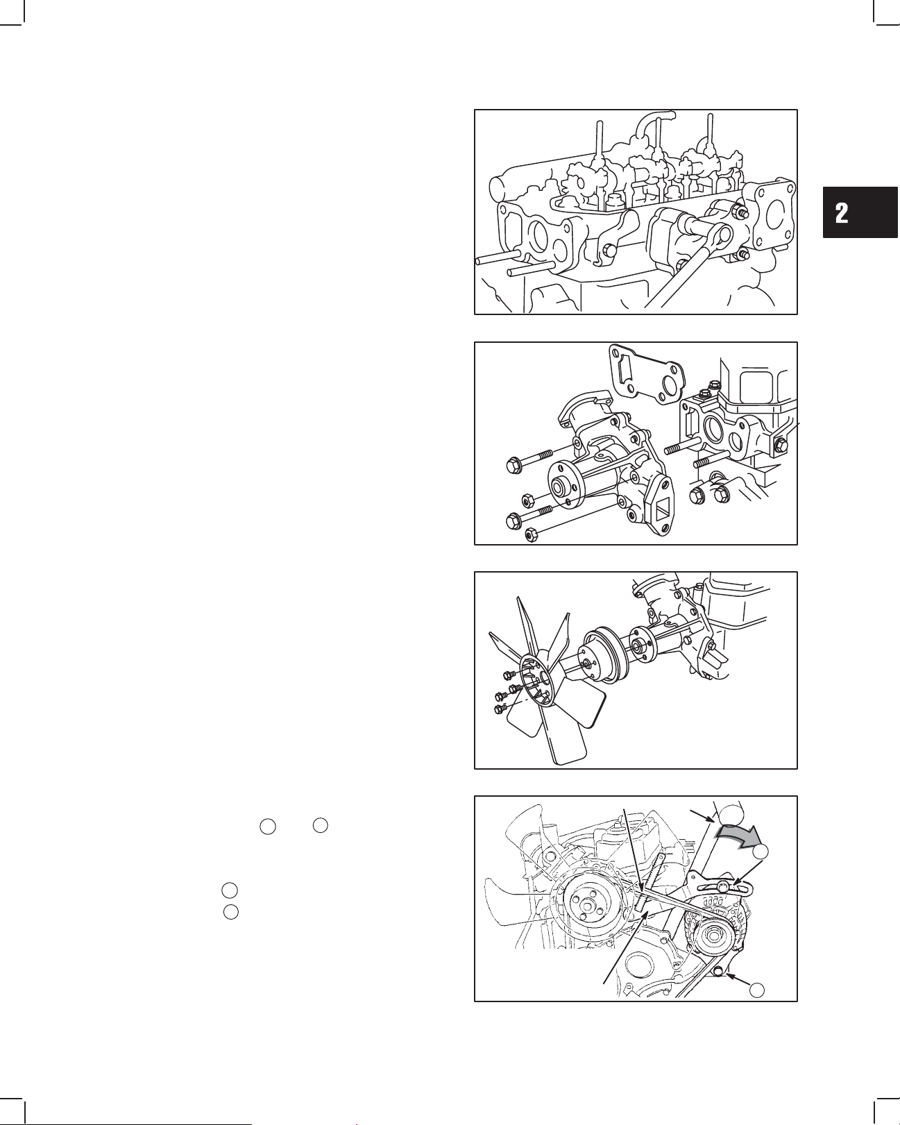
7. Install exhaust manifold with new gasket, Fig. 38.
a. Torque screws to 19.0 Nm (170 in. lbs.).
GENERAL ASSEMBLY
1. Install water pump with new gasket, Fig. 39.
a. Torque screws and nuts to 19.0 Nm (170 in.
lbs.).
CYLINDER HEAD AND VALVES
Fig. 38 – Install Exhaust Manifold
2. Install water pump pulley, Fig. 40.
3. Install fan (if equipped).
a. Torque screws to 7.0 Nm (60 in. lbs.).
4. Install V-belt, Fig. 41.
5. Install alternator bolts A and B .
Belt deflection limit is 10–12 mm/10 kg
(3/8–1/2 in/22 lbs.).
a. Torque bolt A to 19.0 Nm (170 in. lbs.).
b. Torque bolt B to 61.0 Nm (45 ft. lbs.).
Fig. 39 – Install Water Pump
Fig. 40 – Install Water Pump Pulley And Fan
BELT
HANDLE
A
3/8 – 1/2 Inch
(10 – 12 mm)
BELT MOVEMENT
Fig. 41 – Adjusting V-belt
B
13
Page 26
CYLINDER HEAD AND VALVES
No. 1 piston at TDC, of
Rotate Crankshaft 360
2
ADJUST VALVES
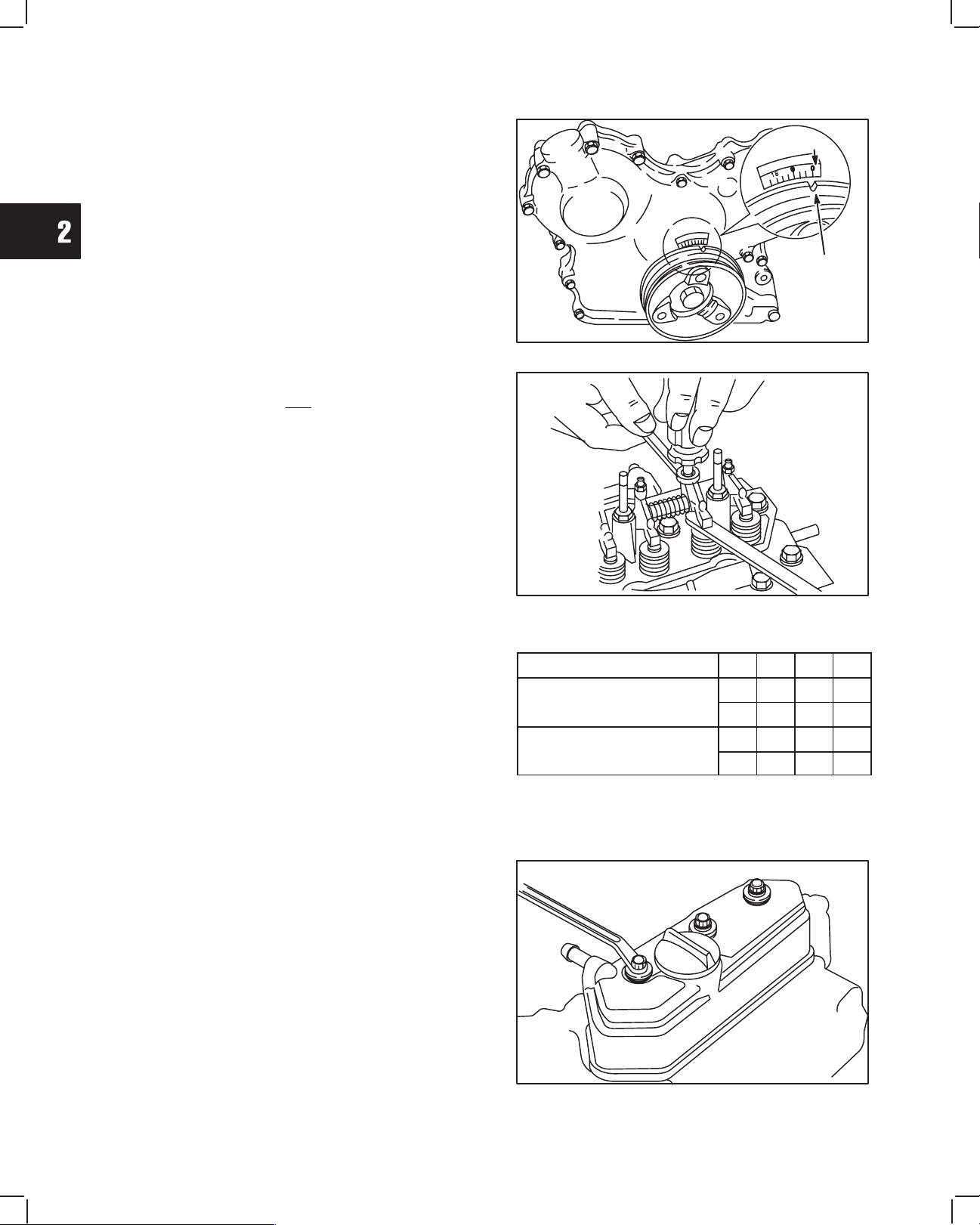
1. Before adjusting valves, make sure that No. 1
cylinder is at TDC – compression stroke, Fig. 42.
a. Adjust valves and check, Fig. 43.
Valve Clearance (cold) IN and EX 0.20 mm (0.008 in.)
b. Torque adjusting screws and jam nuts to 11.0
Nm (95 in. lbs.).
REFERENCE
POINT
Fig. 42 – Set Cylinder No. 1 at TDC
TIMING
MARK
With No. 1 piston at TDC of compression stroke, check
and adjust valve clearances for cylinders shown in
chart at right.
Rotate crankshaft one complete turn (360°)"clockwise
to check and adjust remaining valves.
2. Install valve cover with new rubber seal, Fig. 44.
a. Torque cover nuts to 7.0 Nm (50 in. lbs.).
NOTE: Make sure rubber seal is in groove in
valve cover.
Fig. 43 – Adjust Valve Clearances
Piston Position Cylinder 1 2 3
IN
EX
IN
EX
l l
l l
l
No. 1 piston at TDC, of
compression stroke
Rotate Crankshaft 360°
clockwise
l
14
Fig. 44 – Install Valve Cover
Page 27
3
BRIGGS & STRATTON DAIHATSU 3 CYLINDER
LIQUID-COOLED DIESEL ENGINE REPAIR MANUAL (MS-1055)
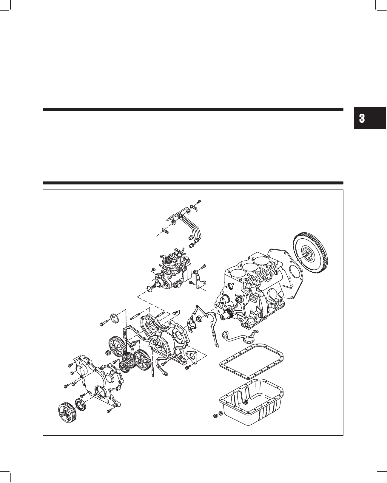
Section 3
Timing Gears and Gear Case
Section Contents
Page
REMOVE TIMING GEAR COVER AND GEARS 2. . . . . . . . . . . . . . . . . . . . . . . . . . . . . . . . . . . . . . . . . . . . . . . . . . . . . .
CHECKING GEARS 3. . . . . . . . . . . . . . . . . . . . . . . . . . . . . . . . . . . . . . . . . . . . . . . . . . . . . . . . . . . . . . . . . . . . . . . . . . . . . .
REMOVE GEAR CASE 4. . . . . . . . . . . . . . . . . . . . . . . . . . . . . . . . . . . . . . . . . . . . . . . . . . . . . . . . . . . . . . . . . . . . . . . . . . .
REPLACE TIMING GEAR COVER OIL SEAL 5. . . . . . . . . . . . . . . . . . . . . . . . . . . . . . . . . . . . . . . . . . . . . . . . . . . . . . . .
ASSEMBLE TIMING GEAR CASE AND GEARS 5. . . . . . . . . . . . . . . . . . . . . . . . . . . . . . . . . . . . . . . . . . . . . . . . . . . . . .
1MAY 2002
Page 28
3
TIMING GEARS AND GEAR CASE
REMOVING TIMING GEAR COVER
AND GEARS
Make sure that #1 cylinder is at TDC, compression
stroke. See Section 2, Fig. 6.
Remove V-belt and fan (if equipped). Drain oil from
engine.
NOTE: Clean areas around fuel lines and injec-
tors to prevent dirt entry.
1. Remove the following parts, Fig. 1.
a. Glow plug wiring.
b. Glow plugs.
c. Injector pump bracket.
d. Remove fuel delivery lines.
2. Remove the following parts, Fig. 2.
a. Remove oil pan and discard gasket.
b. Remove oil pick-up tube and strainer. Discard
gasket.
A
B
Fig. 1 – Remove Fuel Delivery Lines
OIL PICK-UP
TUBE
D
C
3. Remove bell housing adapter screw if equipped.
and install flywheel holder, Tool #19418.
4. LEAVE TOOL INSTALLED.
a. Remove crankshaft pulley using Tool
# 19420, Fig. 3.
5. Remove timing gear cover, Fig. 4.
a. Discard timing gear cover gasket.
Fig. 2 – Removing Oil Pan
FLYWHEEL
HOLDER
Fig. 3 – Removing Crankshaft Pulley
Fig. 4 – Removing Timing Gear Cover
2
Page 29
3
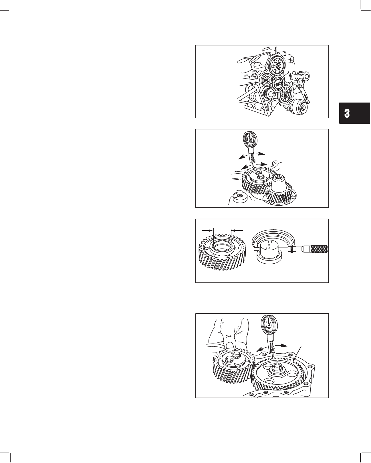
6. Remove oil pump drive gear, Fig. 5.
a. Check oil pump drive gear for damaged teeth.
CHECKING GEARS
Inspect gear teeth for wear or damage.
CHECK GEARS IN SEQUENCE SHOWN.
1. Check gear backlash between idler gear and
crankshaft gear using dial indicator as shown in
Fig. 6.
a. Set tip of indicator on gear tooth, then rock
idler gear back and forth noting indicator
reading.
NOTE: Crankshaft must not turn while checking.
TIMING GEARS AND GEAR CASE
OIL
PUMP
GEAR
Fig. 5 – Removing Oil Pump Gear
IDLER
GEAR
CRANKSHAFT
GEAR
2. If backlash exceeds 0.2 mm (.008”) check idler
gear bearing and shaft for wear, Fig. 7.
Reject Dimension: Idler Gear ID –
34.17 mm (1.345”)
Idler Gear Shaft OD –
33.91 mm (1.335”)
a. If idler gear bearing and shaft are within
specification, replace with new idler gear and
recheck.
b. If backlash exceeds 0.2 mm (.008”) with NEW
idler gear, crankshaft gear is worn.
NOTE: If crankshaft gear is worn the crankshaft
must be replaced.
3. Hold idler gear as shown and check gear backlash
between camshaft timing gear and idler gear using
dial indicator, Fig. 8.
Camshaft timing gear backlash must not exceed
0.2 mm (.008”).
NOTE: Idler gear must not turn while checking.
Fig. 6 – Checking Idler Gear Backlash
IDLER
IDLER
GEAR
GEAR
SHAFT
Fig. 7 – Checking Idler Gear And Shaft
CAMSHAFT
TIMING
GEAR
IDLER
GEAR
Fig. 8 – Checking Camshaft Timing Gear Backlash
3
Page 30
3
TIMING GEARS AND GEAR CASE
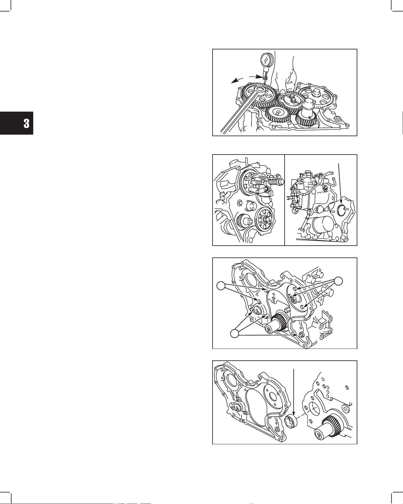
4. Hold idler gear as shown and check gear backlash
between injector pump timing gear and idler gear
using dial indicator, Fig. 9.
Injector pump timing gear backlash must not exceed
0.2 mm (.008”).
NOTE: Idler gear must not turn while checking.
If gears are worn it is recommended that they be
replaced as a set.
REMOVE GEAR CASE
1. Remove injector pump timing gear with a three jaw
puller, Fig. 10.
a. Remove 2 nuts and injector pump. Discard
O-ring.
Fig. 9 – Checking Injector Pump
Timing Gear Backlash
O-RING
2. Remove parts in sequence shown, Fig. 11.
a. Remove 3 screws and camshaft retainer.
b. Remove remaining 5 screws.
3. Remove timing gear case and discard gasket,
Fig. 12.
a. Remove oil pump rotor from cylinder block.
Fig. 10 – Removing Injector Pump
B
B
Fig. 11 – Removing Timing Gear Case
ROTOR
A
Fig. 12 – Remove Timing Gear Case
4
Page 31

3
REPLACE TIMING GEAR COVER OIL SEAL
1. Drive out oil seal.
2. Use seal driver, Tool #19423, to install new oil seal,
Fig. 13.
ASSEMBLE TIMING GEAR
CASE AND GEARS
1. Clean and lubricate oil pump rotor with engine oil
and install in cylinder block, Fig. 14.
a. ID mark on rotor must face cylinder block.
TIMING GEARS AND GEAR CASE
Fig. 13 – Replacing Oil Seal
ID MARK
2. Install timing gear case with new gasket. Install
camshaft retainer, Fig. 15.
NOTE: It may be necessary to rotate oil pump
drive to engage oil pump rotors.
NOTE: Position camshaft retainer so that center
hole does not interfere with camshaft.
Note position, length and number of screws as shown.
a. M6 x 28 mm (M6 x 1.1”): 4
b. M6 x 18 mm (M6 x 0.7”): 3
c. M6 x 16 mm (M6 x 0.6”): 1
Torque screws to 8.0 Nm (70 in. lbs.).
3. Assemble injector pump to gear case with new
O-ring and install nuts and support bracket screw
finger tight, Fig. 16.
NOTE: Pump must be able to rotate.
a. Align timing mark on injector pump with timing
mark on gear case.
NOTE: See Section 10 for injector pump tim-
ing procedure.
OIL PUMP
ROTOR
Fig. 14 – Installing Oil Pump Rotor
C
A
Fig. 15 – Installing Timing Gear Case
B
A
TIMING
MARKS
Fig. 16 – Install Injector Pump
5
Page 32

TIMING GEARS AND GEAR CASE
3
4. Assemble idler gear shaft with arrow up, as shown
in Fig. 17.
Engine models 432000 and 582000 after date code
990111007, and all engine models 522000 are
equipped with right angle helical timing gears. Timing
marks are identified by letters (A, AA, B, BB, etc.),
instead of numbers. The timing procedure is the same.
5. With crankshaft key at 12 o’clock position,
assemble idler gear so that timing mark 11 (AA) is
aligned with timing mark 1 (A) on crankshaft gear,
timing mark 22 (BB) is aligned with timing mark 2
(B) on camshaft gear, and timing mark 33 (CC) is
aligned with timing mark 3 (C) on injector pump
gear, as shown in Fig. 18.
a. Install oil pump gear.
ARROW
UP
CRANKSHAFT
KEY
12 O’CLOCK
Fig. 17 – Installing Idler Gear Shaft
6. Torque screws as shown, Fig. 19.
a. Camshaft Gear: 41.0 Nm (30 ft. lbs.)
b. Idler Gear: 25.0 Nm (220 in. lbs.)
c. Injector Pump Gear: 61.0 Nm (45 ft. lbs.)
d. Oil Pump Gear: 19.0 Nm (170 in. lbs.)
7. Install timing gear cover with new gasket. Note
position, length and number of screws as shown,
Fig. 20.
a. M6 x 55 mm (M6 x 2.5”): 3
b. M6 x 45 mm (M6 x 2.1”): 2
c. M6 x 30 mm (M6 x 1.1”): 9
d. M6 nut: 2
Torque screws and nuts to 8.0 Nm (70 in. lbs.).
Fig. 18 – Aligning Timing Marks – Typical
C
D
Fig. 19 – Torque Screws
C
B
B
C
C
D
D
A
B
A
A
C
Fig. 20 – Installing Timing Gear Cover
6
Page 33

3
8. Install crankshaft pulley with timing mark at
12 o’clock position (#1 cylinder), Fig. 21.
NOTE: Be sure alignment pin in crankshaft gear
is seated in hole in pulley.
a. Torque screw to 88.0 Nm (65 ft. lbs.).
b. Remove flywheel holder.
9. Install oil pick-up tube and strainer with new
gasket. Torque to 8.0 Nm (70 in. lbs.).
a. Apply a small bead of Permatex No. 2 or
similar sealant to crankcase areas shown,
Fig. 22.
b. Install oil pan with new gasket.
c. Torque screws and nuts to 8.0 Nm
(70 in. lbs.).
TIMING GEARS AND GEAR CASE
Fig. 21 – Installing Crankshaft Pulley
SEALANT
10. Install glow plugs, wiring and fuel delivery lines.
a. Torque glow plugs to 17.0 Nm (150 in. lbs.).
b. Torque fuel delivery lines to 25.0 Nm
(220 in. lbs.), Fig. 23.
11. Install V-belt and fan (if equipped).
Fig. 22 – Installing Oil Pan
Fig. 23 – Installing Fuel Delivery Lines
7
Page 34

4
BRIGGS & STRATTON DAIHATSU 3 CYLINDER
LIQUID-COOLED DIESEL ENGINE REPAIR MANUAL (MS-1055)
Section 4
Flywheel and Rear Seal Retainer
Section Contents
Page
REMOVING OIL PAN AND FLYWHEEL 1. . . . . . . . . . . . . . . . . . . . . . . . . . . . . . . . . . . . . . . . . . . . . . . . . . . . . . . . . . . . .
REMOVING REAR SEAL RETAINER 2. . . . . . . . . . . . . . . . . . . . . . . . . . . . . . . . . . . . . . . . . . . . . . . . . . . . . . . . . . . . . . .
REPLACING OIL SEAL 2. . . . . . . . . . . . . . . . . . . . . . . . . . . . . . . . . . . . . . . . . . . . . . . . . . . . . . . . . . . . . . . . . . . . . . . . . . .
INSTALLING REAR SEAL RETAINER AND FLYWHEEL 2. . . . . . . . . . . . . . . . . . . . . . . . . . . . . . . . . . . . . . . . . . . . . . .
INSTALL OIL PAN 3. . . . . . . . . . . . . . . . . . . . . . . . . . . . . . . . . . . . . . . . . . . . . . . . . . . . . . . . . . . . . . . . . . . . . . . . . . . . . . . .
REMOVING PAN AND FLYWHEEL
Drain oil from engine.
1. Remove oil pan screws and nuts. Remove oil pan
and discard gasket Fig. 1.
2. Install flywheel holder, Tool #19418
a. Remove flywheel screws and flywheel, Fig. 2.
Inspect flywheel for cracks or damage. Inspect
flywheel ring gear for worn, chipped or cracked teeth.
If ring gear is worn or damaged the flywheel must be
replaced.
Fig. 1 – Removing Oil Pan
FLYWHEEL
HOLDER
Fig. 2 – Removing Flywheel
1MAY 2002
Page 35

4
FLYWHEEL AND REAR SEAL RETAINER
REMOVE REAR SEAL RETAINER
Remove rear seal retainer and discard gasket, Fig. 3.
REPLACING OIL SEAL
1. Remove oil seal, Fig. 4.
Fig. 3 – Removing Seal Retainer
2. Lubricate outside diameter of oil seal.
a. Using seal driver, Tool #19424 install new oil
seal, Fig. 5.
INSTALLING REAR SEAL RETAINER AND
FLYWHEEL
1. Install rear seal retainer with new gasket, Fig. 6.
a. Torque screws to 6.0 Nm (50 in. lbs.).
Fig. 4 – Removing Oil Seal
Fig. 5 – Installing Oil Seal
RETAINER
GASKET
Fig. 6 – Installing Seal Retainer
2
Page 36

2. Install flywheel, Fig. 7.
NOTE: Apply Permatex No. 2 or similar sealant
to flywheel screws.
a. Torque flywheel screws to 47.0 Nm
(35 ft. lbs.).
Remove flywheel holder.
4
FLYWHEEL AND REAR SEAL RETAINER
Fig. 7 – Installing Flywheel
INSTALL OIL PAN
1. Install oil pan with new gasket, Fig. 8.
a. Apply a small bead of Permatex No. 2 or
similar sealant to crankcase areas shown.
b. Torque screws and nuts to 8.0 Nm
(70 in. lbs.).
SEALANT
Fig. 8 – Installing Oil Pan
3
Page 37

5
BRIGGS & STRATTON DAIHATSU 3 CYLINDER
LIQUID-COOLED DIESEL ENGINE REPAIR MANUAL (MS-1055)
Section 5
Cylinder Block Disassembly
Section Contents
Page
ENGINE STAND FIXTURE 2. . . . . . . . . . . . . . . . . . . . . . . . . . . . . . . . . . . . . . . . . . . . . . . . . . . . . . . . . . . . . . . . . . . . . . . .
CYLINDER BLOCK DISASSEMBLY 3. . . . . . . . . . . . . . . . . . . . . . . . . . . . . . . . . . . . . . . . . . . . . . . . . . . . . . . . . . . . . . . . .
1MAY 2002
Page 38

5
CYLINDER BLOCK DISASSEMBLY
ENGINE STAND
An automotive type engine stand is recommended when complete engine disassembly is required. See drawings
below for dimensions to make an engine stand mounting fixture. The engine stand shown below is manufactured by
Snap-On.
215 mm
65 mm
8-3/8”
HOLES
80 mm
60 mm
45 mm 39 mm
50 mm
107 mm
57 mm
Mounting Plate
1/2” THICK
THRU HOLE
2 THRU
HOLES
13/32”
13”
1-1/2”
Engine Stand Fixture
65 mm
45 mm
21/32”
5/8”
1-1/2” DIA.
2
Page 39

5
CYLINDER BLOCK DISASSEMBLY
CYLINDER BLOCK DISASSEMBLY
1. Remove cylinder head. See Sec. 2.
2. Remove oil pan, oil pick up tube, timing cover,
gears and gear case. See Sec. 3.
3. Remove flywheel and rear seal retainer. See
Sec. 4.
4. Remove starter motor, Fig. 1.
5. Remove alternator bracket and alternator, Fig. 2.
STARTER MOTOR
Fig. 1 – Removing Starter And Bracket
ALTERNATOR
BRACKET
6. Remove valve lifters, Fig. 3.
a. Number lifters so that they may be re-installed
in the same position.
7. Remove camshaft, Fig. 4.
NOTE: Use care when removing camshaft to
prevent damaging cam bearing, journals
and lobes.
Fig. 2 – Removing Alternator
VALVE LIFTER
Fig. 3 – Removing Valve Lifters
CAMSHAFT
Fig. 4 – Removing Camshaft
3
Page 40

CYLINDER BLOCK DISASSEMBLY
8. Remove connecting rod and piston assemblies,
Fig. 5.
NOTE: Remove carbon or ridge from cylinder and
number connecting rod/piston assemblies before removing from cylinders.
a. Remove connecting rod cap with lower
bearing.
b. Push connecting rod and piston out through
top of cylinder.
c. Reassemble connecting rod cap to connect-
ing rod to prevent interchanging components.
9. Remove crankshaft main bearing caps, keeping
main bearings with their respective caps, Fig. 6.
NOTE: Main bearing caps are numbered 1
through 4.
5
Fig. 5 – Removing Connecting Rod Assembly
10. Remove crankshaft, Fig. 7.
a. Remove crankshaft thrust washers (#3 main
bearing).
b. Remove upper main bearings from saddles
and place with respective bearing caps.
Fig. 6 – Removing Main Bearing Caps
SHIMS
#3 MAIN
BEARING
Fig. 7 – Removing Crankshaft
4
Page 41

6
BRIGGS & STRATTON DAIHATSU 3 CYLINDER
LIQUID-COOLED DIESEL ENGINE REPAIR MANUAL (MS-1055)
Section 6
Cylinder Block Inspection and Repair
Section Contents
Page
CHECKING CYLINDER BLOCK 1. . . . . . . . . . . . . . . . . . . . . . . . . . . . . . . . . . . . . . . . . . . . . . . . . . . . . . . . . . . . . . . . . . . .
REPLACING CAMSHAFT BEARING 2. . . . . . . . . . . . . . . . . . . . . . . . . . . . . . . . . . . . . . . . . . . . . . . . . . . . . . . . . . . . . . . .
REPLACING CAMSHAFT PLUG 3. . . . . . . . . . . . . . . . . . . . . . . . . . . . . . . . . . . . . . . . . . . . . . . . . . . . . . . . . . . . . . . . . . .
CHECKING CYLINDER BLOCK
Remove all traces of sealant and gasket material from
mounting surfaces. Inspect cylinder block for damage,
cracks and stripped threads. Inspect cylinder bores for
damage or scores.
1. Check cylinder block deck for distortion, Fig. 1.
Distortion Limit: 0.08 mm (.003”)
2. If cylinder block exceeds limit shown, it may be
resurfaced, Fig. 2.
Cylinder Block Height
Model Series 430000
Std: 229.20-229.80 mm (9.023-9.047”)
Minimum Dimension:
229.10 mm (9.019”) (After Resurfacing)
Model Series 520000 & 580000 Std:
238.70-239.30 mm (9.397-9.421”)
Minimum Dimension:
238.60 mm (9.3937”) (After Resurfacing)
Fig. 1 – Checking Cylinder Block
Fig. 2 – Cylinder Block Height
1MAY 2002
Page 42

CYLINDER BLOCK INSPECTION AND REPAIR
6
3. Check cylinder bores for wear, Fig. 3.
Standard Bore Size:
Model Series 430000 & 520000:
68.00-68.030 mm (2.6770-2.6783”)
Model Series 580000:
72.00-72.030 mm (2.8346-2.8358”)
a. Measure cylinder bore in 6 points at right
angles as shown, Fig. 3.
b. If cylinder bore is worn more than 0.075 mm
(.003”) or more than 0.035 mm (.0015”) out of
round, it must be resized.
Always resize to exactly .25 mm (.010”) over standard
bore size. If this is done accurately, the service
oversize rings and pistons will fit perfectly and proper
clearances will be maintained.
4. Check valve lifter bore, Fig. 4.
Std. Dimension: 18.018 mm (.7094”)
Reject: 18.05 mm (.711”)
5. Check valve lifter, Fig. 4.
Std. Dimension: 17.98 mm (.708”)
Reject: 17.91 mm (.7051”)
AREA OF
NORMAL
WEAR
MEASURE CYLINDER
BORE IN SIX
POSITIONS SHOWN
TO DETERMINE
TAPER & OUT OF
ROUND.
TOP OF RING TRAVEL
(BELOW RIDGE)
CENTER OF RING TRAVEL
BOTTOM OF RING TRAVEL
Fig. 3 – Checking Cylinder Bore
6. Check camshaft bearing, Fig. 5.
Replace if greater than 36.06 mm (1.420”).
REPLACING CAMSHAFT BEARING
1. Remove camshaft bearing, Fig. 6.
a. Use camshaft bearing puller, Tool #19421.
Fig. 4 – Checking Valve Lifter And Bore
Fig. 5 – Checking Cam Bearing
Fig. 6 – Removing Cam Bearing
2
Page 43

2. Install camshaft bearing, Fig. 7.
a. Use camshaft bearing driver, Tool #19422.
NOTE: Notch on camshaft bearing must face out.
Be sure oil hole in bearing is aligned with
oil hole in cylinder block.
REPLACING CAMSHAFT PLUG
1. Remove rear camshaft plug, Fig. 8.
a. Use a wood dowel or brass rod to prevent
damage to camshaft bearing.
6
CYLINDER BLOCK INSPECTION AND REPAIR
Fig. 7 – Installing Cam Bearing
2. Install new camshaft plug using camshaft bearing
driver, Tool #19422.
a. Install camshaft plug flush with cylinder block,
Fig. 9.
If cylinder block is being resized, the following
parts should be removed so that cylinder block
may be thoroughly cleaned.
1. Remove oil pressure switch, water gallery plug
and oil filter adapter, Fig. 10.
Fig. 8 – Removing Camshaft Plug
Fig. 9 – Installing Camshaft Plug
PLUG
ADAPTER
SWITCH
Fig. 10 – Removing Oil Pressure Switch
3
Page 44

CYLINDER BLOCK INSPECTION AND REPAIR
2. Remove timing gear oil nozzle, Fig. 11.
3. When re-installing oil nozzle, oil hole must be
positioned at 45°"angle, pointing towards idler
gear, Fig. 12.
6
OIL NOZZLE
Fig. 11 – Removing Oil Nozzle
IDLER GEAR
Fig. 12 – Installing Oil Nozzle
4
Page 45

7
BRIGGS & STRATTON DAIHATSU 3 CYLINDER
LIQUID-COOLED DIESEL ENGINE REPAIR MANUAL (MS-1055)
Section 7
Crankshaft, Camshaft and Bearings
Section Contents
Page
CHECKING CRANKSHAFT 1. . . . . . . . . . . . . . . . . . . . . . . . . . . . . . . . . . . . . . . . . . . . . . . . . . . . . . . . . . . . . .
CHECKING MAIN BEARING CLEARANCES 2. . . . . . . . . . . . . . . . . . . . . . . . . . . . . . . . . . . . . . . . . . . . . . .
CHECKING CONNECTING ROD BEARING CLEARANCES 3. . . . . . . . . . . . . . . . . . . . . . . . . . . . . . . . . .
CHECKING CRANKSHAFT END PLAY 3. . . . . . . . . . . . . . . . . . . . . . . . . . . . . . . . . . . . . . . . . . . . . . . . . . . .
CHECKING CAMSHAFT 4. . . . . . . . . . . . . . . . . . . . . . . . . . . . . . . . . . . . . . . . . . . . . . . . . . . . . . . . . . . . . . . . .
CHECKING CRANKSHAFT
Inspect crankshaft journals for grooves or signs of
scoring. If found, crankshaft must be re-ground or
replaced.
1. Check the main bearing and crankpin journals for
wear and taper, Fig. 1.
Standard size:
Main – 41.976-42.000 mm (1.6526-1.6535”)
Crankpin – 36.976-37.000 mm (1.4557-1.4567”)
Maximum out of round and taper: 0.02 mm
(0.0008”).
If crankshaft journals are not within specification, the
crankshaft may be re-ground and .25 mm (.010”)
undersize bearings installed. See illustrated parts list
for part numbers.
2. Check the crankshaft for run-out at #3 main
bearing journal, Fig. 2.
Maximum Run-out: 0.06 mm (0.0024”)
a. If run-out exceeds specification shown, the
crankshaft must be replaced.
Fig. 1 – Checking Journals
Fig. 2 – Checking Run-out
1MAY 2002
Page 46

CRANKSHAFT, CAMSHAFT AND BEARINGS
3. Check crankshaft timing gear teeth for damaged
teeth, Fig. 3.
NOTE: See Section 3 for procedure to check
crankshaft timing gear for wear.
If crankshaft timing gear teeth are damaged or worn,
the crankshaft must be replaced.
CHECKING MAIN BEARING CLEARANCES
If main bearings show signs of flaking or scoring,
bearings must be replaced.
Main bearing saddles in cylinder block, main bearing
caps, main bearings and crankshaft journals must be
clean and free of oil.
1. With upper main bearings installed, install crankshaft.
a. Lay a strip of plastigage lengthwise on journal,
Fig. 4.
Do not lay plastigage across oil hole in crankshaft
journal.
2. Assemble main bearing cap with bearing and
torque to 58.3 Nm (43 ft. lbs.), Fig. 5.
7
Fig. 3 – Checking Timing Gear
PLASTIGAGE
Fig. 4 – Install Plastigage
DO NOT ALLOW CRANKSHAFT TO ROTATE.
3. Remove the bearing cap. Measure the plastigage
at its widest point, Fig. 6. If the clearance is not
within specification, replace the bearings.
Crankshaft Main Bearing Clearance:
STD: 0.020-0.044 mm (0.0008-0.0017”)
Reject: 0.07 mm (0.0028”)
Repeat procedure for each main bearing.
Fig. 5 – Torque Bearing Cap
Fig. 6 – Measure Clearance
2
Page 47

CHECKING CONNECTING ROD BEARING
CLEARANCES
If connecting rod bearings show signs of flaking or
scoring, bearings must be replaced.
Connecting rod bearings and crankpin journals must
be clean and free of oil.
1. With upper bearing assembled to connecting rod,
install connecting rod.
a. Lay a strip of plastigage lengthwise on journal,
Fig. 7.
Do not lay plastigage across oil hole in crankpin
journal.
2. Assemble connecting rod cap with bearing and
torque to 36.0 Nm (320 in. lbs.), Fig. 8.
DO NOT ALLOW CRANKSHAFT TO ROTATE.
7
CRANKSHAFT, CAMSHAFT AND BEARINGS
PLASTIGAGE
Fig. 7 – Install Plastigage
3. Remove the connecting rod cap. Measure the
plastigage at its widest point, Fig. 9. If the
clearance is not within specification, replace the
bearings.
Connecting Rod Bearing Clearance:
STD: 0.020-0.044 mm (0.0008-0.0017”)
Reject: 0.07 mm (0.0028”)
Repeat procedure for each connecting rod.
CHECKING CRANKSHAFT END PLAY
With thrust washers installed, check crankshaft end
play at #3 main bearing as shown, Fig. 10.
Crankshaft End Play:
STD: 0.020-0.24 mm (0.0008-0.0094”)
Limit: 0.30 mm (0.012”)
If end play exceeds limit, .125 mm (.005”) over size
thrust washers are available. See illustrated parts list.
Fig. 8 – Torque Rod Cap
Fig. 9 – Measure Clearance
Fig. 10 – Checking Crankshaft End Play
3
Page 48

CRANKSHAFT, CAMSHAFT AND BEARINGS
CHECKING CAMSHAFT
1. Measure camshaft lobe height, Fig. 11. If lobes are
not to specification, replace the camshaft.
Intake and Exhaust:
STD: 30.065-30.135 mm (1.184-1.186”)
Reject: 29.965 mm (1.18”)
2. Measure camshaft journals, Fig. 12.
STD: Front – 35.959-35.975 mm
(1.4157-1.4163”)
Reject: 35.890 mm (1.413”)
STD: Center – 35.910-35.955 mm
(1.4138-1.4155”)
Reject: 35.84 mm (1.411”)
STD: Rear – 35.910-35.955 mm
(1.4138-1.4155”)
Reject: 35.84 mm (1.411”)
7
Fig. 11 – Checking Camshaft Lobes
3. Measure camshaft run-out, Fig. 13.
Maximum Run-out: 0.03 mm (0.0012”).
a. If run-out exceeds specification shown, the
camshaft must be replaced.
Fig. 12 – Checking Camshaft Journals
Fig. 13 – Checking Run-out
4
Page 49

8
BRIGGS & STRATTON DAIHATSU 3 CYLINDER
LIQUID-COOLED DIESEL ENGINE REPAIR MANUAL (MS-1055)
Section 8
Piston, Rings and Connecting Rod
Inspection and Assembly
Section Contents
Page
DISASSEMBLE PISTON AND CONNECTING ROD 1. . . . . . . . . . . . . . . . . . . . . . . . . . . . . . . . . . . . . . . . . . . . . . . . . . .
CHECKING PISTON AND RINGS 2. . . . . . . . . . . . . . . . . . . . . . . . . . . . . . . . . . . . . . . . . . . . . . . . . . . . . . . . . . . . . . . . . .
CHECKING PISTON PIN AND CONNECTING ROD 2. . . . . . . . . . . . . . . . . . . . . . . . . . . . . . . . . . . . . . . . . . . . . . . . . .
ASSEMBLE PISTON AND CONNECTING ROD 3. . . . . . . . . . . . . . . . . . . . . . . . . . . . . . . . . . . . . . . . . . . . . . . . . . . . . .
ASSEMBLE PISTON RINGS TO PISTON 4. . . . . . . . . . . . . . . . . . . . . . . . . . . . . . . . . . . . . . . . . . . . . . . . . . . . . . . . . . . .
DISASSEMBLE PISTON AND
CONNECTING ROD
1. Remove compression rings and oil ring using ring
expander, Tool #19340, Fig. 1.
a. Then remove coil expander.
2. Disassemble piston from connecting rod, Fig. 2.
a. Remove piston pin retainers.
b. Piston pin is a slip fit.
PISTON
Fig. 1 – Removing Piston Rings
Fig. 2 – Disassembling Piston/Connecting Rod
1MAY 2002
Page 50

8
PISTON, RINGS AND CONNECTING ROD INSPECTION AND ASSEMBLY
CHECKING PISTON AND RINGS
If the cylinder bore is to be resized there is no reason to
check the piston as a new oversized piston will be
used.
If the cylinder is not going to be resized and the piston
shows no signs of scoring, the piston should be
checked.
1. Check side clearance of ring grooves using NEW
rings, Fig. 3. If a 0.12 mm (0.005”) feeler gauge
can be inserted, the ring groove is worn. The
piston must be replaced.
Fig. 3 – Checking Ring Grooves
2. Check ring end gap, Fig. 4.
a. Clean carbon from end of rings and using the
piston, insert approximately 100 mm (3.9”)
into cylinder (below ring travel).
NEW PISTON RING
Ring End Gap Reject Size
Compression Rings Oil Ring
0.70 mm (0.028”)
0.70 mm
(0.028”)
3. Check piston pin bore, Fig. 5.
Engine Models: 432447, 522447, 582447
a. Replace if greater than 18.03 mm (0.710”) or
.01 mm (.0004”) out of round.
Engine Models: 58A447, 588447
b. Replace if greater than 21.03 mm (0.828”) or
.01 mm (.0004”) out of round.
CHECKING PISTON PIN AND
CONNECTING ROD
1. Check piston pin, Fig. 6.
Engine Models: 432447, 522447, 582447
a. Replace if less than 17.98 mm (0.708”) or
.01 mm (.0004”) out of round.
Engine Models: 58A447, 588447
b. Replace if less than 20.98 mm (0.826”) or
.01 mm (.0004”) out of round.
CHECK END GAP
BELOW RING TRAVEL
Fig. 4 – Checking End Gap
Fig. 5 – Checking Piston Pin Bore
Fig. 6 – Checking Piston Pin
2
Page 51

PISTON, RINGS AND CONNECTING ROD INSPECTION AND ASSEMBLY
2. Check piston pin bearing, Fig. 7.
Engine Models: 432447, 522447, 582447
a. Replace if greater than 18.03 mm (0.710”) or
.01 mm (.0004”) out of round.
Engine Models: 58A447, 588447
b. Replace if greater than 21.03 mm (0.828”) or
.01 mm (.0004”) out of round.
3. Check crankpin bearing end of connecting rod for
out of round, Fig. 8.
a. With bearing inserts removed, assemble
connecting rod cap and torque to 36.0 Nm
(320 in. lbs.).
Maximum out of round: 0.02 mm (0.0008”)
b. If out of round exceeds specification shown,
the connecting rod must be replaced.
8
Fig. 7 – Checking Piston Pin Bearing
4. Check for bent or twisted connecting rod, Fig. 9.
NOTE: Thrust faces must be free of any burrs or
nicks or connecting rod will not lay flat on
surface plate.
a. With connecting rod on a surface plate, any
distortion will be evident by a rocking motion.
b. If a 0.05 mm (0.002”) feeler gauge can be
inserted at piston pin end of connecting rod the
rod must be replaced.
ASSEMBLE PISTON AND
CONNECTING ROD
Assemble piston to connecting rod, Fig. 10.
NOTE: Arrow on piston and ID mark on rod must
face same side.
1. Lubricate piston pin with engine oil before assembly.
a. Be sure retainers are seated properly in
piston.
Fig. 8 – Checking Crankpin Bearing End
Fig. 9 –Checking Connecting Rod
ID
MARK
Fig. 10 – Assembling Piston And Rod
3
Page 52

8
PISTON, RINGS AND CONNECTING ROD INSPECTION AND ASSEMBLY
ASSEMBLE PISTON RINGS TO PISTON
1. Install piston rings using ring expander, Tool
#19340, Fig. 11.
a. Install oil ring coil expander making sure wire
is inserted fully into coil.
b. Install oil ring.
c. Install center compression ring then, top
compression ring with ID marks up.
2. Stagger ring end gaps as shown, Fig. 12.
WIRE
COIL
EXPANDER
Fig. 11 – Installing Piston Rings
TOP RING
ID
MARK
ID
MARK
OIL RING
TOP
CENTER
OIL
SECOND RING
Fig. 12 – Stagger Ring End Gaps
4
Page 53

9
BRIGGS & STRATTON DAIHATSU 3 CYLINDER
LIQUID-COOLED DIESEL ENGINE REPAIR MANUAL (MS-1055)
Section 9
Cylinder Block Assembly
Section Contents
Page
INSTALL CRANKSHAFT 1. . . . . . . . . . . . . . . . . . . . . . . . . . . . . . . . . . . . . . . . . . . . . . . . . . . . . . . . . . . . . . . . . . . . . . . . . .
INSTALL PISTONS AND CONNECTING RODS 2. . . . . . . . . . . . . . . . . . . . . . . . . . . . . . . . . . . . . . . . . . . . . . . . . . . . . .
GENERAL ASSEMBLY
Oil Pickup Tube 3. . . . . . . . . . . . . . . . . . . . . . . . . . . . . . . . . . . . . . . . . . . . . . . . . . . . . . . . . . . . . . . . . . . . . . . . . . . . . . .
Rear Seal Retainer and Starter Motor 3. . . . . . . . . . . . . . . . . . . . . . . . . . . . . . . . . . . . . . . . . . . . . . . . . . . . . . . . . . . .
Flywheel 3. . . . . . . . . . . . . . . . . . . . . . . . . . . . . . . . . . . . . . . . . . . . . . . . . . . . . . . . . . . . . . . . . . . . . . . . . . . . . . . . . . . . .
INSTALL TIMING GEAR CASE, CAMSHAFT AND GEARS 4. . . . . . . . . . . . . . . . . . . . . . . . . . . . . . . . . . . . . . . . . . . . .
INSTALL ALTERNATOR 6. . . . . . . . . . . . . . . . . . . . . . . . . . . . . . . . . . . . . . . . . . . . . . . . . . . . . . . . . . . . . . . . . . . . . . . . . . .
INSTALL CRANKSHAFT
Install main bearings in cylinder block, Fig. 1.
NOTE: Upper bearing has an oil groove and oil
holes.
1. Install upper main bearings in their respective
saddles.
a. Be sure bearing is seated in saddle and tang in
bearing is aligned with notch in saddle.
b. Lubricate bearings with engine oil.
2. Install lower main bearings in bearing caps, Fig. 2.
a. Be sure bearing is seated in bearing cap and
tang in bearing is aligned with notch in bearing
cap.
b. Lubricate bearings with engine oil.
OIL
HOLES
Fig. 1 – Installing Upper Main Bearings
GROOVES
MAY 2002
Fig. 2 – Installing Lower Main Bearings
1
Page 54

CYLINDER BLOCK ASSEMBLY
9
3. Install crankshaft with gear facing front of cylinder
block, Fig. 3. Take care not to damage journals or
bearings.
a. Install crankshaft shims on #3 main bearing
web with grooves facing out.
b. Lubricate journals with engine oil.
4. Install main bearing caps, Fig. 4. Lubricate
threads of screws with engine oil.
a. Install bearing caps in their respective
positions with arrows facing front.
b. Starting with #3 bearing cap, torque bearing
caps one at a time in sequence shown to 58.0
Nm (43 ft. lbs.).
c. Recheck crankshaft end play.
Crankshaft End Play: 0.025-0.24 mm
(0.0008-0.0094”)
NOTE: After torquing bearing cap, make sure
crankshaft rotates freely before proceeding to next bearing cap.
INSTALL
SHIMS
#3 MAIN
BEARING
Fig. 3 – Installing Crankshaft
FRONT
ARROW
FRONT
3
#1
#2
#3
Fig. 4 – Installing Main Bearing Caps
412
#4
INSTALL PISTONS AND
CONNECTING RODS
1. Install connecting rod bearings, Fig. 5. Be sure
tang on bearing is seated in notch in connecting
rod and cap.
a. Install a piece of vinyl tubing over each
connecting rod screw to prevent damage to
screw threads or crankpin when installing
piston and connecting rod.
2
VINYL TUBING
NOTCH
ID MARK
Fig. 5 – Installing Connecting Rod Bearings
Page 55

Rotate crankshaft so that crankpin is at bottom of
stroke. Then, lubricate cylinder walls, piston and rings,
bearings and crankpins.
2. Using ring compressor, Tool #19070, install piston
and connecting rod assemblies with arrow on
piston facing front, Fig. 6.
a. Install connecting rod cap with ID mark facing
front. Lubricate threads and torque nuts to
34.0 Nm (320 in. lbs.).
NOTE: After torquing rod cap, make sure crank-
shaft rotates freely before proceeding to
next cylinder.
GENERAL ASSEMBLY
1. Install gasket, oil pick-up tube and strainer, Fig. 7.
a. Torque screws to 8.0 Nm (70 in. lbs.).
9
CYLINDER BLOCK ASSEMBLY
FRONT
Fig. 6 – Installing Piston And Connecting Rod
ID MARK
2. Install gasket and rear seal retainer, Fig. 8.
a. Torque screws to 6.0 Nm (50 in. lbs.).
3. Install starter motor.
a. Torque screws to 34.0 Nm (25 ft. lbs.).
4. Install flywheel, Fig. 9.
a. Install flywheel holder, Tool #19418.
b. Apply Permatex No. 2 or similar sealant to
flywheel screws and torque to 47.0 Nm
(35 ft. lbs.).
Fig. 7 – Installing Oil Pick-Up
REAR
SEAL
RETAINER
Fig. 8 – Installing Rear Seal Retainer
FLYWHEEL
HOLDER
Fig. 9 – Installing Flywheel
3
Page 56

CYLINDER BLOCK ASSEMBLY
INSTALL TIMING GEAR CASE, CAMSHAFT
AND GEARS
1. Lubricate oil pump rotor with engine oil and install
in cylinder block, Fig. 10.
a. ID mark on rotor must face cylinder block.
2. Install timing gear case with new gasket.
NOTE: It may be necessary to rotate oil pump
drive to engage oil pump rotors.
Note position, length and number of screws as shown,
Fig. 11.
a. M6 x 28 mm (M6 x 1.1”): 4
b. M6 x 16 mm (M6 x .6”): 1
Torque screws to 8.0 Nm (70 in. lbs.).
9
ID MARK
OIL PUMP
ROTOR
Fig. 10 – Installing Oil Pump Rotor
B
A
A
3. Lubricate, then install camshaft in cylinder block,
Fig. 12. Take care not to damage lobes or cam
bearing.
a. Install camshaft retainer.
b. M6 x 18 mm (M6 x 0.7”): 3
Torque screws to 8.0 Nm (70 in. lbs.).
NOTE: Position camshaft retainer so that center
hole does not interfere with camshaft.
4. Rotate crankshaft so that crankshaft key is at
12 o’clock position as shown in Fig. 13.
RETAINER
CRANKSHAFT
KEY 12 O’CLOCK
Fig. 11 – Installing Gear Case
Fig. 12 – Installing Camshaft
Fig. 13 – Rotate Crankshaft
4
Page 57

5. Assemble injector pump to gear case with new
O-ring and install nuts and support bracket
screw finger tight, Fig. 14.
NOTE: Pump must be able to rotate
a. Align timing mark on injection pump with
timing mark on gear case.
NOTE: See Section 10 for injector pump
timing procedure.
6. Assemble idler gear shaft with ID mark up, as
shown in Fig. 15.
ID MARK
UP
9
CYLINDER BLOCK ASSEMBLY
Fig. 14 – Install Injector Pump
IDLER GEAR
SHAFT
TIMING
MARKS
Engine models 432000 and 582000 after date code
990111007, and all engine models 522000 are
equipped with right angle helical timing gears. Timing
marks are identified by letters (A, AA, B, BB, etc.),
instead of numbers. The timing procedure is the same.
7. With crankshaft key at 12 o’clock position, assemble idler gear so that timing mark 11 (AA) is
aligned with timing mark 1 (A) on crankshaft gear,
timing mark 22 (BB) is aligned with timing mark 2
(B) on camshaft gear, and timing mark 33 (CC) is
aligned with timing mark 3 (C) on injector pump
gear, as shown in Fig. 16.
a. Install oil pump gear.
8. Torque screws as shown, Fig. 17.
a. Camshaft Gear: 41.0 Nm (30 ft. lbs.)
b. Idler Gear: 25.0 Nm (220 in. lbs.)
c. Injector Pump Gear: 61.0 Nm (45 ft. lbs.)
d. Oil pump Gear: 19.0 Nm (170 in. lbs.)
Fig. 15 – Assemble Idler Gear Shaft
CRANKSHAFT
KEY
12 O’CLOCK
Fig. 16 – Aligning Timing Marks
C
A
B
D
Fig. 17 – Torque Screws
5
Page 58

CYLINDER BLOCK ASSEMBLY
9
9. Install timing gear cover with new gasket. Note
position, length and number of screws as shown,
Fig. 18.
a. M6 x 55 mm (M6 x 2.5”): 3
b. M6 x 45 mm (M6 x 2.1”): 2
c. M6 x 30 mm (M6 x 1.1”): 9
d. M6 nut: 2
Torque screws and nuts to 8.0 Nm (70 in. lbs.).
10. Install crankshaft pulley with timing mark at
12 o’clock position (#1 cylinder), Fig. 19.
NOTE: Be sure alignment pin in crankshaft gear
is seated in hole in pulley.
a. Torque screw to 88.0 Nm (65 ft. lbs.).
b. Remove flywheel holder.
C
B
B
C
C
D
A
A
D
C
Fig. 18 – Installing Timing Cover
FLYWHEEL HOLDER
INSTALL ALTERNATOR
1. Install alternator bracket and alternator, Fig. 20.
a. Torque screws to 19.0 Nm (170 in. lbs.).
GENERAL ASSEMBLY
1. Lubricate tappets with engine oil and install in
cylinder block.
2. See Section 2 for installation of cylinder head and
related components.
Fig. 19 – Installing Pulley
Fig. 20 – Install Alternator
6
Page 59

10
BRIGGS & STRATTON DAIHATSU 3 CYLINDER
LIQUID-COOLED DIESEL ENGINE REPAIR MANUAL (MS-1055)
Section 10
Fuel System and Related Components
Section Contents
Page
GENERAL INFORMATION 1. . . . . . . . . . . . . . . . . . . . . . . . . . . . . . . . . . . . . . . . . . . . . . . . . . . . . . . . . . . . . . . .
FUEL SYSTEM COMPONENTS 2. . . . . . . . . . . . . . . . . . . . . . . . . . . . . . . . . . . . . . . . . . . . . . . . . . . . . . . . . . .
INJECTION PUMP TIMING SPECIFICATIONS 3. . . . . . . . . . . . . . . . . . . . . . . . . . . . . . . . . . . . . . . . . . . . . . .
INJECTOR PUMP
Checking Injector Pump Timing 4. . . . . . . . . . . . . . . . . . . . . . . . . . . . . . . . . . . . . . . . . . . . . . . . . . . . . . . . .
Adjusting Injector Pump Timing 5. . . . . . . . . . . . . . . . . . . . . . . . . . . . . . . . . . . . . . . . . . . . . . . . . . . . . . . . .
INJECTORS
Remove Injectors 6. . . . . . . . . . . . . . . . . . . . . . . . . . . . . . . . . . . . . . . . . . . . . . . . . . . . . . . . . . . . . . . . . . . . .
Checking Injectors 7. . . . . . . . . . . . . . . . . . . . . . . . . . . . . . . . . . . . . . . . . . . . . . . . . . . . . . . . . . . . . . . . . . . .
Install Injectors 8. . . . . . . . . . . . . . . . . . . . . . . . . . . . . . . . . . . . . . . . . . . . . . . . . . . . . . . . . . . . . . . . . . . . . . .
FUEL FILTER – GENERAL 8. . . . . . . . . . . . . . . . . . . . . . . . . . . . . . . . . . . . . . . . . . . . . . . . . . . . . . . . . . . . . . . .
Draining Water Collector 9. . . . . . . . . . . . . . . . . . . . . . . . . . . . . . . . . . . . . . . . . . . . . . . . . . . . . . . . . . . . . . .
Change Fuel Filter 9. . . . . . . . . . . . . . . . . . . . . . . . . . . . . . . . . . . . . . . . . . . . . . . . . . . . . . . . . . . . . . . . . . . .
FUEL SHUT OFF SOLENOID 9. . . . . . . . . . . . . . . . . . . . . . . . . . . . . . . . . . . . . . . . . . . . . . . . . . . . . . . . . . . . .
Checking Fuel Shut-Off Solenoid Wiring 9. . . . . . . . . . . . . . . . . . . . . . . . . . . . . . . . . . . . . . . . . . . . . . . . .
INJECTOR PUMP IDENTIFICATION 10. . . . . . . . . . . . . . . . . . . . . . . . . . . . . . . . . . . . . . . . . . . . . . . . . . . . . .
ENGINE SPEED IDENTIFICATION CHART 10. . . . . . . . . . . . . . . . . . . . . . . . . . . . . . . . . . . . . . . . . . . . . . . .
Adjust Idle Speed 11. . . . . . . . . . . . . . . . . . . . . . . . . . . . . . . . . . . . . . . . . . . . . . . . . . . . . . . . . . . . . . . . . . . . .
Adjust Top No Load Speed 11. . . . . . . . . . . . . . . . . . . . . . . . . . . . . . . . . . . . . . . . . . . . . . . . . . . . . . . . . . . . .
The fuel system consists of a gear driven injector pump with fuel delivery and return lines and injector nozzles for each
cylinder. Diesel fuel is drawn from the fuel tank through the fuel filter by the feed pump which is incorporated in the
injection pump and delivers fuel to the injectors at a constant volume regardless of pump RPM. The feed pump also
circulates fuel through the pump for lubrication purposes.
A single pump plunger meters and distributes fuel in the correct firing order through an injector nozzle in each combustion chamber. Excess fuel from the injector nozzles and pump is returned to the fuel tank by way of the overflow valve
and return line. This system of fuel circulation lubricates and cools the injection pump and also warms the fuel in the
fuel tank to help prevent fuel waxing in cold weather.
CAUTION: Always use clean fresh diesel fuel with a minimum of 40 cetane. DO NOT use kerosene. The injection
pump requires diesel fuel for lubrication. Damage to the injection pump and/or engine may result if kerosene is used.
Servicing the fuel injection system requires highly specialized equipment and procedures. Consult the Yellow Pages
under Engines-Diesel-Fuel Injection Service & Parts for the nearest diesel fuel injection specialist if the injector pump
or injector nozzles require servicing.
See Section 3 for procedure for removing and installing injector pump.
MAY 2002
1
Page 60

FUEL SYSTEM COMPONENTS
10
FUEL FILTER
FUEL LINE
FUEL INJECTION SYSTEM COMPONENTS
FUEL RETURN LINE
FUEL DELIVERY LINE
INJECTOR PUMP
INJECTOR
FUEL RETURN LINE
FUEL TANK
2
Page 61

10
TABLE 1
Injection Pump Timing
Engine Date Code Before 99010100
Model/Type No. Timing Specification
INJECTOR PUMP
432447-0150-E2
522447-0105-E2
522447-0106-E2
522447-0107-E2
522447-0108-E2
522447-0109-E2
582447-0105-E2
582447-0125-E2
582447-0130-E2
582447-0131-E2
0.93 ± .03 mm (.0365” ± .001”)
0.93 ± .03 mm (.0365” ± .001”)
0.93 ± .03 mm (.0365” ± .001”)
0.93 ± .03 mm (.0365” ± .001”)
0.93 ± .03 mm (.0365” ± .001”)
0.93 ± .03 mm (.0365” ± .001”)
0.93 ± .03 mm (.0365” ± .001”)
0.81 ± .03 mm (.032” ± .001”)
0.93 ± .03 mm (.0365” ± .001”)
0.81 ± .03 mm (.032” ± .001”)
TABLE 2
Injection Pump Timing
Engine Date Code After 98123100
Model Series Timing Specification
432447 – All
0.90 ± .03 mm (.035” ± .001”)
522447 – All
582447 – All
58A447 – All
588447
0.90 ± .03 mm (.035” ± .001”)
0.81 ± .03 mm (.032” ± .001”)
0.90 ± .03 mm (.035” ± .001”)
3
Page 62

INJECTOR PUMP
Checking Injector Pump Timing
NOTE: Clean areas around fuel lines and injec-
tors to prevent any dirt from entering
injector nozzles or delivery valve ports
when fuel delivery lines are removed.
1. Remove fuel delivery lines from injector pump and
injector nozzles, Fig. 1.
2. Set No. 1 piston at TDC:
a. Rotate crankshaft until timing mark on pulley
is aligned with reference point on timing cover,
Fig. 2.
b. If intake and exhaust valves have clearance,
No. 1 piston is at TDC – compression stroke.
c. If intake and exhaust valves do not have clear-
ance, turn crankshaft pulley one complete
revolution. Valves will then have clearance.
10
Fig. 1 – Removing Fuel Lines
REFERENCE
POINT
TIMING
MARK
3. Remove distributor head screw with washer and
install injector pump timing gage,dial indicator Tool
# 19441, Fig. 3.
4. Slowly rotate crankshaft counter-clockwise until
dial indicator needle just stops moving. Set dial
indicator at ‘‘0,” Fig. 4.
NOTE: When indicator needle just stops moving,
carefully rock crankshaft clockwise slightly, then counter-clockwise slightly to verify
absolute ‘‘0.”
Fig. 2 – Align Timing Marks
Fig. 3 – Install Timing Tool
DIAL INDICATOR
TOOL #19441
Fig. 4 – Setting Indicator
4
Page 63

5. Slowly rotate crankshaft clockwise until timing
mark on pulley aligns with reference point on gear
case cover (TDC), Fig. 5. Note dial indicator
reading.
NOTE: Do not rotate crankshaft past TDC. If
crankshaft is rotated past TDC rotate
crankshaft back to ‘‘0” and repeat
procedure.
6. Refer to timing specification tables on page 3 for
correct specification by engine model and type or
code number.
If indicator reading is within specification, injector
pump is properly timed. Proceed to step 6.
If indicator reading is not within specification, see
procedure for adjusting injector pump timing.
7. Remove timing gage and install distributor screw
with new washer, Fig. 6.
a. Torque screw to 17.0 Nm (150 in. lbs.).
8. Install fuel delivery lines.
a. Torque to 25.0 Nm (220 in. lbs.).
10
METRIC INDICATOR
SHOWN
Fig. 5 – Checking Timing
INJECTOR PUMP
Adjusting Injector Pump Timing
Refer to timing specification tables on page 3 for correct
specification by engine model and type or code number.
1. Loosen injector pump mounting nuts and pump
support bracket screw, Fig. 7. Rotate pump toward
cylinder head as far as it will go.
NOTE: Loosen nuts and screw only enough to
allow pump to be rotated with some
resistance.
Perform Steps 2 through 4 as described in ‘‘Checking
Injector Pump Timing”.
2. Slowly rotate crankshaft clockwise until timing
mark on pulley aligns with reference point on gear
case cover (TDC), Fig. 8.
NOTE: Do not rotate crankshaft past TDC. If
crankshaft is rotated past TDC rotate
crankshaft back to ‘‘0” and repeat
procedure.
Fig. 6 – Install Distributor Screw
Fig. 7 – Loosen Pump
REFERENCE
DISTRIBUTOR
SCREW
POINT
Fig. 8 – Align Timing Marks
TIMING
MARK
5
Page 64

INJECTOR PUMP
3. While observing dial indicator, slowly rotate injector pump away from cylinder head until indicator
shows correct specification. Hold injector pump in
this position and tighten outside pump mounting
nut, Fig. 9.
NOTE: Do not rotate pump past specification. If
pump is rotated past specification, rotate
pump back toward cylinder head and
repeat procedure.
4. To verify that timing is correct, rotate crankshaft
counter-clockwise until dial indicator reads ‘‘0.”
Then rotate crankshaft clockwise until timing
mark on pulley aligns with reference point on gear
case cover (TDC). Indicator should be within
specification, Fig. 10.
5. Torque injector pump mounting nuts and pump
support bracket screw to 19.0 Nm (170 in. lbs.).
10
OUTSIDE MOUNTING
NUT
Fig. 9 – Adjusting Timing
6. Remove timing gage and install distributor screw
with new washer, Fig. 11.
a. Torque screw to 17.0 Nm (150 in. lbs.).
7. Install fuel delivery lines.
a. Torque to 25.0 Nm (220 in. lbs.).
INJECTORS
Remove Injectors
NOTE: Use care to prevent any dirt from entering
injector holes or delivery valve ports when
fuel delivery lines are removed.
1. Remove fuel delivery lines, Fig. 12.
2. Disconnect fuel return line hose.
3. Remove nuts and fuel return line.
a. Discard fuel return line gaskets.
METRIC INDICATOR
SHOWN
Fig. 10 – Verify Timing
DISTRIBUTOR
Fig. 11 – Installing Distributor Screw
SCREW
Fig. 12 – Removing Fuel Lines
6
Page 65

10
INJECTORS
4. Remove injector nozzles, Fig. 13.
a. Discard injector gaskets.
NOTE: Handle injectors with extreme care. Do
not drop!
Always use new fuel return line and injector nozzle
gaskets when servicing fuel system.
Fig. 13 – Removing Injectors
Checking Injectors
Fuel injector nozzle testing requires highly specialized equipment and procedures. Consult the Yellow Pages under
Engines-Diesel-Fuel Injection Service & Parts for the nearest diesel fuel injection specialist.
The procedures and specifications listed are provided as an aid to the fuel injection specialist when testing injector
nozzles.
1. With injector installed on a nozzle tester, operate
the handle rapidly several times to clean off any
carbon deposits on the injector port, Fig. 14.
2. Check ‘‘pop off” pressure of injector.
Specification: 135 – 145 Bar
(1955 – 2100 psi)
If injector is not within specification, the injector shim
may be changed, Fig. 15.
Replacement shims are available in .025 mm increments from .7 to 1.95 mm.
NOTE: As the shim thickness increases or de-
creases by .025 mm, injection pressure
will vary about 5 Bar (71 psi).
Torque nozzle holder and injector body to 47.0 Nm
(35 ft. lbs.).
Fig. 14 – Checking Injector
SHIM
Fig. 15 – Injector Shim
7
Page 66

INJECTORS
3. Check injector for leakage, Fig. 16.
Maintain injector pressure at approximately 120 Bar
(1707 psi), for about 10 seconds. Make sure there is no
leakage from nozzle or retaining nut area.
4. Check spray pattern of nozzle, Fig. 17.
Operate tester handle rapidly while observing pattern.
Spray pattern should be uniform and centered under
nozzle.
NOTE: A buzzing or chattering sound should also
occur while operating handle. Nozzle
should not drip between pump strokes.
10
Fig. 16 – Checking Leakage
Install Injectors
Install injectors and fuel return line with new gaskets,
Fig. 18. Install fuel delivery lines.
a. Torque injectors to 61.0 Nm (45 ft. lbs.).
b. Torque fuel return line to 27.0 Nm (20 ft. lbs.).
c. Torque fuel delivery lines to 25.0 Nm
(220 in. lbs.).
FUEL FILTER – GENERAL
The fuel filter consists of a replaceable cartridge type
filter with a water level sensor and priming pump,
Fig. 19.
Replace fuel filter cartridge every 800 hours of engine
operation.
The water collector contains a float type sensor that
activates a warning lamp when it collects a minimum of
80 cc’s (2.5 fl. oz.) of water.
Fig. 17 – Checking Spray Pattern
Fig. 18 – Installing Injectors
PRIMER
BUTTON
FILTER
O-RING
FLOATVENT PLUG
DRAIN PLUG
Fig. 19 – Fuel Filter
8
Page 67

10
FUEL FILTER
Draining Water Collector
When warning lamp comes on, drain water collector
as follows:
1. Stop engine.
2. Place a drain pan under filter and loosen vent plug.
3. Loosen drain plug approximately 1 turn and drain
water from filter until only fuel flows from filter.
4. Tighten drain plug and vent plug and wipe up any
spills.
5. Start engine, making sure warning lamp goes out.
Check for leaks.
Checking Float Sensor
The following test will be made with the meter in the
‘‘Diode Test Position” .
Disconnect sensor wire from equipment harness and
remove float sensor from fuel filter.
1. Attach a meter test lead to each terminal in
connector.
2. While holding drain plug in vertical position, raise
float to end of travel, Fig. 20.
a. Meter should make a continuous tone.
3. Now lower float
a. Meter should display OL.
Replace drain plug and float sensor if not to specification.
FUEL SHUT-OFF SOLENOID
When the ignition switch is turned to the ‘‘On” and
‘‘Start” position the fuel shut off solenoid valve opens
allowing fuel to enter the fill port and pressure
chamber. When the keyswitch is turned ‘‘Off” the
solenoid closes shutting off the the fuel supply and the
engine, Fig. 21.
Solenoid is operating if a click is heard when keyswitch
is turned ‘‘On” and ‘‘Off.”
If solenoid does not click, problem may be in equipment wiring to solenoid.
Checking Fuel Shut-Off Solenoid Wiring
The following test will be made with the meter in the
(DC Volts position).
Turn keyswitch to ‘‘Off” position and disconnect
equipment solenoid wire.
1. Attach BLACK meter test lead to a good ground.
2. Attach RED meter test lead to connector in equipment solenoid wire and turn keyswitch to ‘‘On”
position.
3. Meter should display battery voltage, Fig. 22.
a. If meter does not display battery voltage,
check for broken solenoid wire, blown fuse (if
equipped) or defective keyswitch.
Change Fuel Filter
1. Disconnect sensor wire and remove drain plug.
Discard O-ring.
2. Remove fuel filter with a filter wrench.
3. Screw new filter on by hand until gasket contacts
housing. Then tighten 1/3 turn more.
4. Install drain plug with new O-ring and connect
sensor wire.
5. Activate primer button until resistance is felt.
6. Start engine and check for leaks.
FLOAT
Fig. 20 – Checking Sensor
FUEL
SHUT-OFF
SOLENOID
Fig. 21 – Fuel Shut-Off Solenoid
EQUIPMENT
WIRING HARNESS
CONNECTOR
Fig. 22 – Testing Solenoid Wiring
9
Page 68

10
22100 87802
9U1
22100-8780
8U1
22100-87809
8U2
INJECTOR PUMP IDENTIFICATION
IDENTIFICATION CODE
NAME
PLATE
IDENTIFICATION
CODE
7 : 700 cc
8 : 850 cc
9 : 950 cc
DESTINATION
U : USA
J : Japan
X : Except for
USA
SERIAL
NUMBER
TABLE 3
Engine Speed Specification Chart
Pump Mfg. Part No. ID Code Model & Type No. Idle Speed (rpm) Top No Load (rpm)
22100-87801 7U1 432447-0105-E2
22100-8713 7U2 432447-0205-E2
582447-0105-E2
582447-0205-E2
582447-0130-E2
22100-87802 9U1
582447-0230-E2
582447-0219-E2
582447-0222–E2
582447-0221-E2
582447-0225-E2
582447-0232-E2
582447-0125-E2
22100-87806 9U2
582447-0131-E2
582447-0231-E2
7
522447-0105-E2
522447-0108-E2
522447-0106-E2
522447-0109-E2
22100-87810 8U3 522447-0107-E2
22100-87815 8U4 522447-0107-E2
22100-87817 8U5 522447–0107–E2
22100-87811 9U4 58A447–0205–E2
22100-87818 9U5 588447–0205–E2
588447–0216–E2
588447–0230–E2
588447–0225–E2
1200±50 3850±50
1200±50 3850±50
1200±50 3850±50
1200±50 3300±50
1600±50 3600±50
1750±50 3600±50
1050±50 3850±50
1200±50 3400±50
1850±50 3420±50
1700±50 3600±50
1200±50 3850±50
1600±50 3350±50
1850±50 3420±50
1850±50 3420±50
1525±50 2775±50
1540±50 2790±50
1540±50 2790±50
1200±50 3850±50
1200±50 3850±50
1800±50 3600±50
1600±50 3600±50
1050±50 3850±50
10
Page 69

10
ENGINE SPEED
ADJUST IDLE SPEED
Engine should be at operating temperature before
adjusting idle speed.
Make sure speed control lever contacts idle speed
screw with engine at idle.
1. Loosen idle speed screw lock nut and adjust idle
speed screw to obtain RPM specified by model
and type number shown in chart, Fig. 23.
NOTE: Do exceed RPM shown for specific model
and type number.
a. Torque lock nut to 6.0 Nm (50 in. lbs.).
ADJUST TOP NO LOAD SPEED
Engine should be at operating temperature before
adjusting idle speed.
Temporarily disconnect speed control wire at control
bracket on pump.
1. Remove and discard top no load wire and seal.
2. Loosen top no load speed screw lock nut.
3. Move speed control lever to FAST position and
adjust top no load speed screw to RPM specified
by model and type number shown in chart, Fig. 24.
NOTE: Do exceed RPM shown for specific model
and type number.
4. Stop engine and torque lock nut to 6.0 Nm
(50 in. lbs.).
5. Reassemble speed control wire at bracket.
a. Tighten screws securely.
b. Make sure speed control lever contacts top
no load screw when throttle lever is in
FAST position.
IDLE
SPEED
SCREW
LOCK NUT
Fig. 23 – Adjusting Idle Speed
CONTROL
TOP NO
LOAD
SPEED
SCREW
LOCK NUT
Fig. 24 – Adjusting Top No Load Speed
SPEED
LEVER
SPEED
CONTROL
LEVER
11
Page 70

11
BRIGGS & STRATTON DAIHATSU 3 CYLINDER
LIQUID-COOLED DIESEL ENGINE REPAIR MANUAL (MS-1055)
Section 11
Electrical System
Section Contents
Page
ELECTRICAL SYSTEM COMPONENTS 3. . . . . . . . . . . . . . . . . . . . . . . . . . . . . . . . . . . . . . . . . . . . . . . . . . . .
GLOW PLUG SYSTEM
Glow Plug Specifications 4. . . . . . . . . . . . . . . . . . . . . . . . . . . . . . . . . . . . . . . . . . . . . . . . . . . . . . . . . . . . . . .
Remove Glow Plugs 4. . . . . . . . . . . . . . . . . . . . . . . . . . . . . . . . . . . . . . . . . . . . . . . . . . . . . . . . . . . . . . . . . . .
Test Equipment 4. . . . . . . . . . . . . . . . . . . . . . . . . . . . . . . . . . . . . . . . . . . . . . . . . . . . . . . . . . . . . . . . . . . . . . .
Testing Glow Plug 4. . . . . . . . . . . . . . . . . . . . . . . . . . . . . . . . . . . . . . . . . . . . . . . . . . . . . . . . . . . . . . . . . . . . .
PREHEAT TIMER AND GLOW RELAY 5. . . . . . . . . . . . . . . . . . . . . . . . . . . . . . . . . . . . . . . . . . . . . . . . . . . . . .
Testing Preheat Timer 5. . . . . . . . . . . . . . . . . . . . . . . . . . . . . . . . . . . . . . . . . . . . . . . . . . . . . . . . . . . . . . . . .
Testing Glow Relay 5. . . . . . . . . . . . . . . . . . . . . . . . . . . . . . . . . . . . . . . . . . . . . . . . . . . . . . . . . . . . . . . . . . . .
KEYSWITCHES 6. . . . . . . . . . . . . . . . . . . . . . . . . . . . . . . . . . . . . . . . . . . . . . . . . . . . . . . . . . . . . . . . . . . . . . . . . .
14 AMP CHARGING SYSTEM 7. . . . . . . . . . . . . . . . . . . . . . . . . . . . . . . . . . . . . . . . . . . . . . . . . . . . . . . . . . . . .
Test Equipment 7. . . . . . . . . . . . . . . . . . . . . . . . . . . . . . . . . . . . . . . . . . . . . . . . . . . . . . . . . . . . . . . . . . . . . . .
Testing Alternator – AC Output 8. . . . . . . . . . . . . . . . . . . . . . . . . . . . . . . . . . . . . . . . . . . . . . . . . . . . . . . . . .
Testing Regulator-rectifier – DC Output 8. . . . . . . . . . . . . . . . . . . . . . . . . . . . . . . . . . . . . . . . . . . . . . . . . .
Charging Indicator Circuit 9. . . . . . . . . . . . . . . . . . . . . . . . . . . . . . . . . . . . . . . . . . . . . . . . . . . . . . . . . . . . . .
Testing Charging Indicator Bulb And Wiring 9. . . . . . . . . . . . . . . . . . . . . . . . . . . . . . . . . . . . . . . . . . . . . . .
40 AMP CHARGING SYSTEM 10. . . . . . . . . . . . . . . . . . . . . . . . . . . . . . . . . . . . . . . . . . . . . . . . . . . . . . . . . . . .
Test Equipment 10. . . . . . . . . . . . . . . . . . . . . . . . . . . . . . . . . . . . . . . . . . . . . . . . . . . . . . . . . . . . . . . . . . . . . .
Testing Alternator – DC Output 10. . . . . . . . . . . . . . . . . . . . . . . . . . . . . . . . . . . . . . . . . . . . . . . . . . . . . . . .
Disassemble Alternator 11. . . . . . . . . . . . . . . . . . . . . . . . . . . . . . . . . . . . . . . . . . . . . . . . . . . . . . . . . . . . . . . .
Checking Bearings 12. . . . . . . . . . . . . . . . . . . . . . . . . . . . . . . . . . . . . . . . . . . . . . . . . . . . . . . . . . . . . . . . . . .
Install Ball Bearing 13. . . . . . . . . . . . . . . . . . . . . . . . . . . . . . . . . . . . . . . . . . . . . . . . . . . . . . . . . . . . . . . . . . .
Checking Rotor 13. . . . . . . . . . . . . . . . . . . . . . . . . . . . . . . . . . . . . . . . . . . . . . . . . . . . . . . . . . . . . . . . . . . . . .
Check Brushes 13. . . . . . . . . . . . . . . . . . . . . . . . . . . . . . . . . . . . . . . . . . . . . . . . . . . . . . . . . . . . . . . . . . . . . .
Check Regulator 14. . . . . . . . . . . . . . . . . . . . . . . . . . . . . . . . . . . . . . . . . . . . . . . . . . . . . . . . . . . . . . . . . . . . .
Check Rectifier 14. . . . . . . . . . . . . . . . . . . . . . . . . . . . . . . . . . . . . . . . . . . . . . . . . . . . . . . . . . . . . . . . . . . . . .
Assemble Alternator 14. . . . . . . . . . . . . . . . . . . . . . . . . . . . . . . . . . . . . . . . . . . . . . . . . . . . . . . . . . . . . . . . . .
MAY 2002
1
Page 71

11
Section Contents (Continued)
STARTER SYSTEM – GENERAL INFORMATION
STARTER CURRENT DRAW TEST – INSTALLED 17. . . . . . . . . . . . . . . . . . . . . . . . . . . . . . . . . . . . . . . . . .
Test Equipment 17. . . . . . . . . . . . . . . . . . . . . . . . . . . . . . . . . . . . . . . . . . . . . . . . . . . . . . . . . . . . . . . . . . . . . .
Testing Starter 18. . . . . . . . . . . . . . . . . . . . . . . . . . . . . . . . . . . . . . . . . . . . . . . . . . . . . . . . . . . . . . . . . . . . . . .
STARTER CURRENT DRAW TEST – NO LOAD 18. . . . . . . . . . . . . . . . . . . . . . . . . . . . . . . . . . . . . . . . . . . .
Testing Starter (No Load) 18. . . . . . . . . . . . . . . . . . . . . . . . . . . . . . . . . . . . . . . . . . . . . . . . . . . . . . . . . . . . .
STARTER SOLENOID
Test Equipment 19. . . . . . . . . . . . . . . . . . . . . . . . . . . . . . . . . . . . . . . . . . . . . . . . . . . . . . . . . . . . . . . . . . . . . .
Testing Solenoid 19. . . . . . . . . . . . . . . . . . . . . . . . . . . . . . . . . . . . . . . . . . . . . . . . . . . . . . . . . . . . . . . . . . . . .
Remove Solenoid 20. . . . . . . . . . . . . . . . . . . . . . . . . . . . . . . . . . . . . . . . . . . . . . . . . . . . . . . . . . . . . . . . . . . .
Remove Pinion And Clutch Assembly 20. . . . . . . . . . . . . . . . . . . . . . . . . . . . . . . . . . . . . . . . . . . . . . . . . . .
Check Pinion And Clutch Assembly 21. . . . . . . . . . . . . . . . . . . . . . . . . . . . . . . . . . . . . . . . . . . . . . . . . . . .
Assemble Pinion And Clutch Assembly 21. . . . . . . . . . . . . . . . . . . . . . . . . . . . . . . . . . . . . . . . . . . . . . . . .
Install Solenoid 22. . . . . . . . . . . . . . . . . . . . . . . . . . . . . . . . . . . . . . . . . . . . . . . . . . . . . . . . . . . . . . . . . . . . . .
Install Solenoid Contacts And Plunger 22. . . . . . . . . . . . . . . . . . . . . . . . . . . . . . . . . . . . . . . . . . . . . . . . . .
DISASSEMBLE STARTER MOTOR 24. . . . . . . . . . . . . . . . . . . . . . . . . . . . . . . . . . . . . . . . . . . . . . . . . . . . . . .
Inspect Armature Commutator 24. . . . . . . . . . . . . . . . . . . . . . . . . . . . . . . . . . . . . . . . . . . . . . . . . . . . . . . . .
Inspect Brushes 24. . . . . . . . . . . . . . . . . . . . . . . . . . . . . . . . . . . . . . . . . . . . . . . . . . . . . . . . . . . . . . . . . . . . .
Replace Brushes 25. . . . . . . . . . . . . . . . . . . . . . . . . . . . . . . . . . . . . . . . . . . . . . . . . . . . . . . . . . . . . . . . . . . . .
ASSEMBLE STARTER MOTOR 26. . . . . . . . . . . . . . . . . . . . . . . . . . . . . . . . . . . . . . . . . . . . . . . . . . . . . . . . . . .
WIRING DIAGRAMS
14 AMP WIRING DIAGRAMS 27. . . . . . . . . . . . . . . . . . . . . . . . . . . . . . . . . . . . . . . . . . . . . . . . . . . . . . . . . . . . .
40 AMP WIRING DIAGRAMS 28. . . . . . . . . . . . . . . . . . . . . . . . . . . . . . . . . . . . . . . . . . . . . . . . . . . . . . . . . . . . .
Page
2
Page 72

Electrical System Components
(Typical 40 Amp Alternator Shown)
11
KEYSWITCH
PART NO.
3
493625
KEYSWITCH
TERMINAL FUNCTION
2
ACCESSORY & PREHEAT TIMER
4
SOLENOID & PREHEAT TIMER
5
BATTERY
NOTE: TERMINALS 1, 3, 6 NOT USED
2
5
1
6
4
FUEL
FILTER
WATER INDICATOR
LIGHT
STARTER MOTOR
SOLENOID
“IG”
TERMINAL
INJECTION
PUMP
GLOW
LIGHT
PREHEATING TIMER
7
8
GLOW PLUGS
CHARGE INDICATOR
“L”
TERMINAL
1
2
3
4
6
GLOW
RELAY
5
LIGHT
12 VOLT BATTERY
“B”
TERMINAL
Fig. 1
40 AMP
ALTERNATOR
TERMINAL
“B”
“IG”
TERMINAL
“L”
TERMINAL
3
Page 73

GLOW PLUG SYSTEM
Glow Plug
The glow plug is a self regulating type, consisting of
two metal heating element coils; a rush coil and a brake
coil, Fig. 2. The rush coil provides rapid heating of the
tip of the glow plug. The brake coil decreases current to
the glow plug by increasing resistance as the temperature rises, regulating the temperature of the glow plug.
Glow Plug Specifications
11
RUSH
COIL
BRAKE
COIL
Rated Voltage
11V
Rated Current 9.5A
Normal Resistance 1.0 Ω
Remove Glow Plug
Disconnect glow plug wiring from connector.
1. Remove glow plug connector nuts and connector.
2. Remove glow plugs, Fig. 3.
Handle glow plugs with care. Do not drop. Do not
scratch heater section.
Test Equipment
The digital multimeter, Tool #19390 is required to test
the glow plug.
Testing Glow Plug
Fig. 2 – Glow Plug
Fig. 3 – Removing Glow Plugs
With meter selector switch in position, a
continuous tone indicates continuity (complete circuit).
No tone indicates no continuity (incomplete circuit). An
incomplete circuit will be displayed as “OL.”
1. Check glow plug for continuity as shown, Fig. 4.
a. If meter indicates NO continuity, replace glow
plug.
4
Fig. 4 – Testing Glow Plugs
Page 74

PREHEAT TIMER AND GLOW RELAY
The preheat timer and glow relay regulate current to
the glow plugs for preheating and starting. When the
keyswitch is turned to the “On” position, with the engine
cold, the preheat timer activates the glow plugs. An
indicator light lights and remains on while the glow
plugs are preheating the combustion chamber. When
the indicator light goes out, the engine may be started.
When the keyswitch is in the “Start” position, the glow
plugs and light are activated again as the engine is
cranking.
See Fig. 5 for terminal positions of the preheat timer
and glow relay.
Testing Preheat Timer
The following test will be made with the meter in the
(DC Volts position), Fig. 6.
Turn keyswitch to “Off” position.
1. Insert BLACK meter test lead probe into terminal
#4.
2. Insert RED meter test lead probe into terminal #3.
3. Turn keyswitch to “On” position.
a. Glow light should light. Meter should display
1.5 volts maximum.
b. After 5 seconds (approximately), glow light
should go out. Meter should display approximately battery voltage.
4. Replace preheat timer if not to specification.
NOTE: If glow light does not light, replace bulb.
Testing Glow Relay
The following test will be made with the meter in the
(DC Volts position), Fig. 7.
Turn keyswitch to “Off” position.
1. Insert BLACK meter test lead probe into terminal
#8.
2. Insert RED meter test lead probe into terminal #7.
a. Meter should display battery voltage.
3. Turn keyswitch to “On” position.
a. Glow light should light. Meter should display
0.5 volts maximum.
b. After 5 seconds (approximately), glow light
should go out. Meter should display
approximate battery voltage.
4. Replace glow relay if not to specification.
11
GLOW PLUG SYSTEM
1
2
3
PREHEAT TIMER
Fig. 5 – Terminal Positions
1
2
3
Fig. 6 – Testing Preheat Timer
Fig. 7 – Testing Glow Relay
4
7
8
4
8
6
5
GLOW
RELAY
7
6
5
5
Page 75

GLOW PLUG SYSTEM
11
KEYSWITCHES
Two types of keyswitches may be used on Briggs &
Stratton Daihatsu diesel engines.
Fixed Timer Preheat Keyswitch –
Part No. 493625
Keyswitch, Part No. 493625, is used with a preheat
timer and glow relay, Fig. 8. With the keyswitch in the
“On” and “Start” position, battery current is supplied to
the preheat timer and glow relay. See keyswitch
terminal positions and functions, Fig. 8.
See Fig. 78 and Fig. 79 at end of section, for wiring
diagrams for keyswitch No. 493625.
Manual Preheat Keyswitch –
Part No. 825129
The manual preheat keyswitch, Part No. 825129, is
equipped with four positions and six terminals, Fig. 9.
The “G1” terminal provides current to the glow plugs
only when the switch is in the “Heat” position. When the
keyswitch is turned to the “Start” position the “G2”
terminal provides current to the glow plugs while the
engine is cranking. See keyswitch terminal positions
and functions, Fig. 10.
Symbols are shown as they appear on rear of
keyswitch. Note that “B” terminal is connected to
terminal below it, Fig. 10. Keyswitch will not function
without connector.
2 + 5
ON
1 + 3 + 6
OFF
START
2 + 4 +5
NOT
USED
ON
3
2
4
5
1
6
START
2
1
6
3
4
5
Test switch terminals for continuity with keyswitch in positions shown
2
Accessory & Preheat Timer
4
Solenoid & Preheat Timer
5
Battery
NOTE: Terminals 1, 3, 6 Not Used
Fig. 8 – Keyswitch – Fixed Timer Preheat
B+B
B+B+G1
HEAT
Fig. 9 – Keyswitch – Manual Preheat
OFF
ON
B+B+M
START
B+B+S+M+G2
See Fig. 80 and Fig. 81 for wiring diagrams for
keyswitch No. 825129.
HEAT OFF ON START
B
Connector
G1
S
B
S
G2
BBBB
B+B+G1
M
B+B
M
G1
B
G2
Test switch terminals for continuity with keyswitch in positions shown.
Fig. 10 – Terminal Positions And Functions
6
G1
S
B
S
G2
M
B+B+M B+B+S+M+G2
B
Battery (2)
S
Solenoid
G1
Glow Plug (Preheat)
G2
Glow Plug (Cranking)
M
Accessory
M
G1
G2
Page 76

14 AMP CHARGING SYSTEM
The 14 amp charging system consists of two
components:
1. The belt driven permanent magnet alternator
produces AC voltage, Fig. 11. AC output will vary
with engine RPM, from approximately 7 volts AC
at 1000 RPM to 32 volts AC at 3000 RPM.
NOTE: A loose V-belt will cause low AC output.
Belt deflection limit is 9.5-11.5 mm/10 kg.
(3/8-7/16 in./22 lb.).
2. The regulator-rectifier converts the AC current to
DC and regulates current to the battery, Fig. 12.
The charging rate will vary with engine RPM. The
regulator-rectifier is equipped with a charging
indicator light circuit.
NOTE: The regulator-rectifier requires a mini-
mum battery voltage of 6 volts to function.
There will be no charging output if
battery voltage is below 6 volts.
Fig. 78 and Fig. 80 at end of section, show wiring
diagrams for typical 14 amp charging system.
Fig. 11 – 14 Amp Alternator
CHARGE INDICATOR
LIGHT
11
CHARGING SYSTEMS
Test Equipment
The digital multimeter, Tool #19464 and the DC shunt,
Tool #19468, Fig. 13, are required to test the charging
system.
NOTE: The digital multimeter will withstand DC
input of 10-20 amps for up to 30 seconds.
To avoid blowing fuse in meter, the DC
shunt is required.
Replacement fuse is available from your Briggs &
Stratton source of supply. Order Part No. 19449.
Fig. 12 – Regulator-rectifier
19464
19468
Fig. 13 – Test Equipment
7
Page 77

CHARGING SYSTEMS
Testing Alternator – AC Output
The alternator output test will be performed with the
meter in the V~ (AC volts) position, Fig. 14.
Disconnect alternator wires at connector.
Attach meter test leads to alternator output connectors
BEFORE starting engine, Fig. 14.
1. With the engine running at 3300 RPM the output
should be no less than 28 volts AC.
a. If no output or low output is found, replace
alternator.
b. If alternator output is within specification, re-
connect alternator wires and test regulator
rectifier.
11
Fig. 14 – Testing Alternator Output
Testing Regulator-Rectifier – DC Output
The DC Shunt must be installed on the negative (-)
terminal of the battery, Fig. 15. All connections must be
clean and tight for correct amperage readings.
Attach meter test leads BEFORE starting engine.
The regulator-rectifier test will be performed with the
meter in the position.
1. Attach RED meter test lead to RED post terminal
on shunt.
2. Attach BLACK meter test lead to BLACK post
terminal on shunt.
3. With the engine running at 3300 RPM, the output
should be:
* 4 – 14 Amps
* Depending upon battery voltage and/or current draw
on system.
4. If no or low output is found, be sure that regulatorrectifier is grounded properly and all connections
are clean and secure. If there is still no or low
output, replace the regulator-rectifier.
ATTACH NEGATIVE
BATTERY CABLE
BLACK
LEAD
RED
LEAD
NEGATIVE
BATTERY
TERMINAL
Fig. 15 – DC Shunt Installation
8
Page 78

Charging Indicator Circuit
The green wire from the regulator-rectifier is used to
activate the charging indicator light. With the keyswitch
in the “ON” position and the engine not running the
charge indicator light should light, Fig. 16. With the
engine running the light should go out, indicating that
the battery is being charged.
If the charge indicator light does not light when the
keyswitch is in the “ON” position (engine not running),
check the bulb and wiring.
Testing Charging Indicator Bulb And Wiring
The following test will be made with the meter in the
“Diode Test Position” , Fig. 17.
11
CHARGING SYSTEMS
CHARGE INDICATOR
LIGHT
Fig. 16 – Charge Indicator Light
With meter selector switch in position, a
continuous tone indicates continuity (complete circuit).
No tone indicates no continuity (incomplete circuit). An
incomplete circuit will be displayed as “OL.”
Keyswitch must be in OFF position.
1. Disconnect output harness at regulator-rectifier.
2. Check continuity between charging indicator wire
(green) and ground, Fig. 18.
a. If meter indicates continuity, bulb and wiring
are OK. Replace regulator-rectifier.
b. If meter indicates NO continuity, replace bulb
and re-test.
c. If meter indicates NO continuity with new bulb,
the problem must be a broken wire (open
circuit) in the charging indicator circuit.
If the charge indicator light remains on with the engine
running, test the regulator-rectifier DC output. If output
is within specification and charge indicator light
remains on, replace the regulator-rectifier.
Fig. 17 – Meter Setting
HARNESS CONNECTOR
LIGHT
BLUE
GREEN YELLOW
Fig. 18 – Testing Bulb And Wiring
BLACK
WIRE COLOR AND TERMINAL POSITION
GREEN-CHARGE LAMP WIRE
LIGHT
BLUE
RED
9
Page 79

CHARGING SYSTEMS
11
40 AMP CHARGING SYSTEM
Fig. 1 shows wiring diagram for 40 amp charging
system.
The 40 amp charging system consists of a belt driven,
internally regulated alternator, Fig. 19.
The alternator contains a charge light circuit (“L”
terminal). With the keyswitch in the ON position and
the engine not running the charge indicator light should
light. With the engine running the light should go out,
indicating that the battery is being charged.
If the charge indicator light does not light when the
keyswitch is in the ON position (engine not running),
check the bulb and wiring.
Note: A loose V-belt will cause low DC output.
Belt deflection limit is 9.5-11.5 mm/10 kg
(3/8-7/16 in./22 lbs.).
TEST EQUIPMENT
The digital multimeter, Tool #19464 and the DC shunt,
Tool #19468, Fig. 20, are required to test the charging
system.
Note: The digital multimeter will withstand DC
input of 10-20 amps for up to 30 seconds.
To avoid blowing fuse in meter, the DC
shunt is required.
Replacement fuse is available from your Briggs &
Stratton source of supply. Order Part No. 19449.
“L”
TERMINAL
“IG”
TERMINAL
Fig. 19 – 40 Amp Alternator
19464
19468
“B”
TERMINAL
TESTING ALTERNATOR – DC OUTPUT
The DC Shunt must be installed on the negative (-)
terminal of the battery, Fig. 21. All connections must be
clean and tight for correct amperage readings.
Attach meter test leads BEFORE starting engine.
The regulator-rectifier test will be performed with the
meter in the position.
1. Attach RED meter test lead to RED post terminal
on shunt.
2. Attach BLACK meter test lead to BLACK post
terminal on shunt.
3. With the engine running at 2000 RPM, the output
should be:
* 4 – 20 Amps
* Depending upon battery voltage and/or current draw
on system.
4. If no or low output is found, be sure that all
connections are clean and secure.
5. If all connections are OK, replace or repair the
alternator.
Fig. 20 – Test Equipment
ATTACH NEGATIVE
BATTERY CABLE
BLACK
LEAD
RED
LEAD
NEGATIVE
BATTERY
TERMINAL
Fig. 21 – DC Shunt Installation
10
Page 80

DISASSEMBLE ALTERNATOR
1. Remove pulley nut using tool #19491 and 10 mm
deep socket as shown in Fig. 22.
a. Remove pulley and spacer.
Replace pulley if damaged or worn.
2. Remove nut and insulator at “B” terminal.
3. Remove three screws and brush cover, Fig. 23.
B
TERMINAL
11
CHARGING SYSTEMS
Fig. 22 – Remove Pulley
4. Remove two screws, then brush retainer
assembly, Fig. 24.
Important: Length of brush retainer screws are
different. Do not mix.
Screw “A”: 11.5 mm
Screw “B”: 9.0 mm
5. Remove three screws and regulator, Fig. 25.
Fig. 23 – Remove Rear Cover
A
11.5 mm
Fig. 24 – Remove Brush Retainer
B
9.0 mm
Fig. 25 – Remove Regulator
11
Page 81

CHARGING SYSTEMS
6. Remove four stator lead screws from rectifier,
Fig. 26.
a. Carefully straighten stator leads.
b. Remove rectifier.
7. Scribe or place a reference mark on drive end and
brush end housing so that they may be
re-assembled in original position.
8. Remove two nuts and two thru bolts.
9. Remove brush end housing being careful not to
damage stator leads, Fig. 27.
STATOR
LEADS
11
Fig. 26 – Remove Rectifier
STATOR
LEADS
10. Remove rotor from drive end housing, Fig. 28.
Note: Stator is NOT removable.
CHECKING BEARINGS
Ball bearings must rotate freely. If any rough spots are
felt the ball bearing must be replaced.
Note: Rotor and ball bearing are an assembly. If
bearing is worn, replace rotor assembly.
Remove Ball Bearing
1. Remove four screws and bearing retainer, Fig. 29.
2. Support drive housing on blocks.
3. Press out bearing from pulley side of drive end
housing using driver #19416.
DO NOT re-use ball bearings that have been removed
from drive end housing. The bearing races are usually
damaged during removal.
Fig. 27 – Remove Brush End Housing
ROTOR
Fig. 28 – Remove Rotor
19416 DRIVER
Fig. 29 – Remove Bearing Retainer
12
Page 82

11
CHARGING SYSTEMS
INSTALL BALL BEARING
1. Lightly lubricate bearing O.D. with engine oil.
2. Press in new bearing using bearing driver #19226,
Fig. 30.
3. Install retainer and four screws.
CHECKING ROTOR
The following test will be made with the meter in the
“Diode Test Position” .
1. Use digital multimeter and check for continuity
between slip rings as shown, Fig. 31.
a. Meter should make continuous tone
(continuity).
b. If meter displays “OL”, (no continuity) replace
rotor.
2. Check for continuity between slip ring and rotor
shaft.
a. Meter should display “OL”, (no continuity).
3. Measure slip ring diameter, Fig. 32.
19226 DRIVER
Fig. 30 – Install Ball Bearing
1
2
Fig. 31 – Check Rotor
STD: 14.4 mm (.567”)
Reject: 14.0 mm (.551”)
Slip rings may be cleaned with fine sandpaper (#300 –
500 grit).
CHECK BRUSHES
Measure length of brushes protruding from brush
holder, Fig. 33.
STD: 10.5 mm (.413”)
Reject: 8.0 mm (.315”)
Fig. 32 – Check Slip Ring
Fig. 33 – Check Brushes
13
Page 83

CHARGING SYSTEMS
11
CHECK REGULATOR
The following test will be made with the meter in the
“Diode Test Position” .
1. Attach BLACK meter test lead to terminal “A” as
shown, Fig. 34.
2. Contact terminal “B” with RED meter test lead,
Fig. 34.
a. Meter should “beep” once.
b. If meter displays “OL” or makes a continuous
tone, regulator is defective. Replace regulator.
A
Fig. 34 – Check Regulator
CHECK RECTIFIER
The following test will be made with the meter in the
“Diode Test Position” .
1. Attach BLACK meter test lead to “B” terminal,
Fig. 35. Leave attached through Step 3.
2. Contact #1 terminal with RED meter test lead,
Fig. 35.
a. Meter should “beep” once.
b. If meter displays “OL” or makes a continuous
tone, diode is defective. Replace rectifier.
3. Repeat test at #2, #3 and #4 terminals.
a. Results must be the same. Fig. 35 – Check Rectifier
4. Attach RED test lead to one of the three rectifier
mounting holes, Fig. 36. Leave attached through
Step 6.
5. Contact #1 terminal with BLACK meter test lead,
Fig. 36.
a. Meter should “beep” once.
b. If meter displays “OL” or makes a continuous
tone, diode is defective. Replace rectifier.
6. Repeat test at #2, #3 and #4 terminals.
a. Results must be the same.
#4
#3
#4
#3
Fig. 36 – Check Rectifier
B
B
TERMINAL
#1
#2
#1
#2
ASSEMBLE ALTERNATOR
1. Assemble rotor to drive end housing, Fig. 37.
2. Assemble spacer, pulley and nut to rotor shaft.
a. Do not tighten nut at this time.
b. Place pulley side down on work surface.
14
Fig. 37 – Installing Rotor
Page 84

3. Assemble brush end housing to drive end housing
with reference marks aligned, Fig. 38.
Note: Do not damage stator leads.
4. Install thru bolts and nuts.
a. Torque to 5.0 Nm (45 in. lbs.).
5. Align stator wires with holes in rectifier and
assemble rectifier to brush end housing, Fig. 39.
6. Carefully form a “U” bend in stator wires.
a. Install screws and tighten securely.
11
CHARGING SYSTEMS
Fig. 38 – Assemble Housings
RECTIFIER
7. Install regulator with three screws shown, Fig. 40.
8. Assemble cover to brush holder, Fig. 41.
Fig. 39 – Install Rectifier
Fig. 40 – Install Regulator
Fig. 41 – Install Brush Cover
COVER
15
Page 85

CHARGING SYSTEMS
9. Install brush holder.
Important: Length of brush retainer screws are
different. Install as shown, Fig. 42.
Screw “A”: 11.5 mm
Screw “B”: 9.0 mm
10. Install rear cover and three screws, Fig. 43.
a. Torque screws to 3.0 Nm (25 in. lbs.).
11. Install insulator and nut.
a. Torque nut to 4.0 Nm (35 in. lbs.).
11
A
11.5 mm
Fig. 42 – Install Brush Holder
B
9.0 mm
Torque drive pulley using the following procedure,
Fig. 44.
1. Hold nut with tool #19491.
2. With torque wrench, turn 10 mm deep socket
COUNTERCLOCKWISE.
a. Torque to 70.0 Nm (50 ft. lbs.).
TURN WRENCH
COUNTERCLOCK-
WISE
Fig. 43 – Install Cover
HOLD NUT
Fig. 44 – Torque Pulley
16
Page 86

11
STARTER SYSTEM
IDENTIFICATION NUMBER
IDENTIFICATION NUMBER
28100-87805 28100-87806
Fig. 45 – 1.0 Kw (Standard) Fig. 46 – 1.2 Kw (Optional)
STARTER SYSTEM – GENERAL INFORMATION
Two different starter motors are used on Briggs & Stratton Daihatsu diesel engines. The standard motor is rated at 1.0
Kw., Fig. 45. The optional starter is rated at 1.2 Kw., Fig. 46. The starters are identified by their identification numbers.
The starters are similar enough that service procedures and specifications are the same. Where differences occur,
they will be shown.
STARTER CURRENT DRAW TEST – ALL
(Starter Installed)
Important: When making the starter current draw test
make sure that all parasitic load is removed from the
engine and that engine has the correct viscosity oil.
Engine temperature should be at least 21° C (70° F).
Make sure battery and solenoid connections are clean
and tight.
NOTE: Battery voltage must not be below 11.7
volts.
Test Equipment
The following equipment is required to test current
draw of starter, Fig. 47.
1. Digital multimeter, Tool #19464.
2. DC shunt, Tool #19468.
3. Two battery cables with alligator clips.
4. One jumper wire with alligator clips.
5. A fully charged 12 volt battery.
19390
19468
BATTERY
CABLES
JUMPER
WIRE
Fig. 47 – Test Equipment
17
Page 87

STARTER SYSTEM
11
Testing Starter – All
NOTE: To prevent engine from starting, remove
fuel shut off solenoid wire from injector
pump.
The starter current draw test will be performed with the
meter in the position.
The DC Shunt must be installed on the negative (-)
terminal of the battery, Fig. 48.
1. Attach RED meter test lead to RED post terminal
on shunt.
2. Attach BLACK meter test lead to BLACK post
terminal on shunt.
3. Activate starter.
a. Allow 3 seconds for meter reading to stabilize.
4. Current draw should not exceed 140 amps DC.
If amperage draw exceeds specification, remove
starter from engine and perform No Load starter
current draw test.
STARTER CURRENT DRAW TEST – NO LOAD
Remove starter motor.
To hold starter securely while testing, clamp starter
mounting bracket in a vise. DO NOT clamp starter
housing in a vise or field windings or magnets may be
damaged.
NEGATIVE
BATTERY
CABLE
NEGATIVE
CABLE
BLACK
LEAD
RED
LEAD
Fig. 48 – Starter Current Draw Test
BLACK
LEAD
JUMPER
WIRE
RED
LEAD
Testing Starter (No Load)
The No Load starter current draw test will be per-
formed with the meter in the position.
The DC Shunt must be installed on the negative (-)
terminal of the battery, Fig. 49.
1. Attach RED meter test lead to RED post terminal
on shunt.
2. Attach BLACK meter test lead to BLACK post
terminal on shunt.
3. Attach negative battery cable to a good ground
such as drive housing.
4. Attach positive battery cable to battery terminal on
solenoid.
5. Attach one end of jumper wire to solenoid tab
terminal, Fig. 49.
6. Activate starter by contacting positive battery
terminal with other end of jumper wire, Fig. 49.
a. Allow 3 seconds for meter reading to stabilize.
7. Current draw should not exceed 90 amps DC.
If amperage draw exceeds specification, replace
starter.
NEGATIVE
CABLE
JUMPER
WIRE
POSITIVE
CABLE
18
Fig. 49 – No Load Starter Current Draw Test
Page 88

11
.
STARTER SOLENOID
Test Equipment
The starter solenoid test is performed with the starter
removed from the engine.
The following equipment is recommended to test the
solenoid.
1. One battery cable with alligator clips. Fig. 50.
2. A jumper wire.
3. A fully charged 12 volt battery.
Testing Starter Solenoid
1. Attach one end of battery cable to negative battery
terminal and other end of cable to a good ground
such as drive housing. Fig. 51.
2. Attach jumper wire to tab terminal on solenoid.
3. Activate solenoid by contacting positive battery
terminal with other end of jumper wire.
a. Pinion must move outward quickly (engage).
4. Remove jumper wire from positive battery terminal.
a. Pinion must return quickly (disengage).
If pinion does not move, replace the solenoid.
BATTERY
JUMPER
Fig. 50 – Test Equipment
JUMPER
WIRE
Fig. 51 – Testing Solenoid
STARTER SYSTEM
CABLE
WIRE
1
DRIVE HOUSING
2
11
10
12
9
3
5
1
4
7
6
2
8
PINION AND DRIVE CLUTCH
3
DRIVE GEAR
4
RETAINER
5
ROLLER BEARINGS (5)
6
BALL
7
RETURN SPRING
8
SOLENOID
9
ARMATURE
10
STARTER HOUSING
11
BRUSH RETAINER
12
END CAP
EXPLODED VIEW OF STARTER – TYPICAL
19
Page 89

STARTER SYSTEM
Remove Solenoid
1. Remove nut and field coil wire from stud terminal
on solenoid, Fig. 52.
2. Remove through bolts and starter motor, Fig. 53.
DO NOT remove armature from starter housing or it
will be necessary to re-assemble brushes to armature.
11
FIELD COIL WIRE
Fig. 52 – Removing Field Coil Wire
3. Remove two drive end cap screws. Hold starter in
vertical position with drive housing down and
separate solenoid housing from drive housing,
Fig. 54. Note position of solenoid return spring
and ball.
NOTE: The solenoid must be replaced as an
assembly.
Remove Pinion And Clutch Assembly
1. Remove drive gear from bearing. Remove bearing
retainer and five roller bearings, Fig. 55.
2. Remove pinion and clutch assembly from drive
housing.
Fig. 53 – Removing Starter Motor
Fig. 54 – Removing Solenoid
PINION
AND CLUTCH
DRIVE
HOUSING
DOWN
20
Fig. 55 – Removing Pinion And Clutch
Page 90

Check Pinion And Clutch Assembly
Check pinion and gear for damage, Fig. 56. Pinion and
shaft must rotate in clutch in clockwise direction only.
Bearings must turn freely.
NOTE: The pinion and clutch must be replaced as
an assembly.
11
STARTER SYSTEM
CLOCKWISE
Fig. 56 – Checking Pinion And Clutch
Assemble Pinion And Clutch Assembly
1. Lubricate the following components with silicone
grease before assembly, Fig. 57.
NOTE: See insert for correct assembly for type
starter.
a. Clutch gear.
b. Bearing retainer and roller bearings.
c. Drive gear.
d. Pinion shaft bearings.
e. Return spring ball.
f. Return spring.
2. Assemble roller bearings and retainer to drive gear
shaft, Fig. 58.
NOTE: Roller bearings must face drive housing.
Retainer must face solenoid housing.
B
D
A
D
E
Fig. 57 – Assembling Pinion And Clutch
ROLLER BEARINGS
AND RETAINER
C
1 KW
1 KW
1.2 KW
F
3. Mesh drive gear with clutch gear. Install pinion and
clutch assembly and drive gear into drive housing
together, Fig. 59. Install return spring ball in clutch.
Make sure roller bearings remain in position.
Fig. 58 – Assembling Roller Bearings
Fig. 59 – Assembling Drive Housing
21
Page 91

STARTER SYSTEM
Install Solenoid
1. Insert return spring into solenoid plunger.
2. Align pilot hole in solenoid with drive gear shaft
and assemble solenoid to drive housing, Fig. 60.
a. Torque screws to 9.0 Nm (80 in. lbs.).
3. Assemble starter motor to drive housing. Align tab
on starter with notch in drive housing, Fig. 61.
a. Torque screws to 9.0 Nm (80 in. lbs.).
4. Install field coil wire.
a. Torque nut to 8 Nm (70 in. lbs.).
11
DRIVE
HOUSING
DOWN
Fig. 60 – Installing Solenoid
Replace Solenoid Plunger And Contacts
Place starter in a vise with cover plate up.
1. Remove three screws and cover plate.
a. Discard gasket.
2. Remove plunger and spring.
3. Replace contacts if burned or worn.
Note: Contacts and plunger must be replaced
as an assembly.
4. Measure thickness of contact plates with calipers.
Reject Dimension: 0.9 mm (0.035”).
Fig. 61 – Installing Starter Motor
Fig. 62 – Remove Plunger
WEAR
22
Fig. 63 – Checking Contacts
Page 92

5. Remove two nuts with 14 mm wrench, Fig. 64.
6. Remove components in sequence shown, Fig. 65.
Field Wire Terminal Side:
(1) G
(2) F
(3) E
(4) D
(5) C
(6) B
(7) A
11
STARTER SYSTEM
Fig. 64 – Loosen Nuts
Battery Wire Terminal Side:
Before 99010100: 1.0 KW / After 98123100: 1.0 KW
Before 98083100: 1.2 KW / After 98090100: 1.2 KW
(1) N (1) N
(2) M (2) M
(3) L (3) P
(4) K (4) O
(5) J (5) K
(6) I (6) J
(7) H (7) I
(8) H
7. Install components in sequence shown, Fig. 65.
Field Wire Terminal Side:
(1) A
(2) B
(3) C
(4) D
(5) E
(6) F
(7) G
Battery Wire Terminal Side:
Before 99010100: 1.0 KW / After 98123100: 1.0 KW
Before 98083100: 1.2 KW / After 98090100: 1.2 KW
(1) H (1) H
(2) I (2) I
(3) J (3) J
(4) K (4) K
(5) L (5) O
(6) M (6) P
(7) N (7) M
(8) N
8. Do not tighten terminal nuts at this time.
BEFORE 99010100: 1.0 KW / BEFORE 98083100: 1.2 KW
H
I
(1.2 KW)
N
M
L
K
AFTER 98123100: 1.0 KW / AFTER 98090100: 1.2 KW
H
I
N
M
P
O
K
J
D
(1.2 KW)
J
D
(1.0 KW)
C
B
E
F
G
(1.0 KW)
C
B
E
F
G
Fig. 65 – Contact Assemblies
A
A
23
Page 93

STARTER SYSTEM
9. Install new plunger and spring.
10. Place bearing driver, Tool #19422 on plunger and
compress plunger to end of travel. Maintain
pressure.
a. Torque nuts to 17 Nm (150 in. lbs.).
Note: This provides proper contact alignment
with plunger and contact plates.
11. Clean contact plates and plunger contacts.
12. Install cover plate with new gasket.
a. Torque screws to 4 Nm (35 in. lbs.).
DISASSEMBLE STARTER MOTOR
1. Remove starter motor from drive housing.
2. Remove screws and end cap.
3. Remove armature from motor housing, Fig. 67.
11
Fig. 66 – Aligning Contact Plates
If armature drive splines or armature bearings are
damaged or worn, replace armature.
Inspect Armature Commutator
The armature commutator may be cleaned with fine
sandpaper. DO NOT use emery cloth. Commutator
may be machined to no less than 29.0 mm (1.142”),
Fig. 68.
NOTE: Minimum depth of slots between
commutator bars after machining is 0.2
mm (.008”).
The armature should be checked for shorts with a
growler.
Inspect Brushes
Minimum brush dimension is shown below Fig. 69.
1.0 KW Starter: 9 mm (.350”).
1.2 KW Starter: 10 mm (.400”).
If brushes are worn less than specification, replace as
follows.
1.0 KW Starter: Replace brush retainer and brushes
on starter housing.
1.2 KW Starter: Starter housing and brush retainer
must be replaced as an assembly.
Fig. 67 – Disassemble Starter Motor
29.0 mm
Fig. 68 – Commutator Specifications
1.0 KW: 9 mm
1.2 KW: 10 mm
Fig. 69 – Minimum Brush Dimension
24
Page 94

Use digital multimeter and check for continuity
between field coil wire and brushes shown, Fig. 70.
The following test will be made with the meter in the
“Diode Test Position” .
1. Attach either meter test lead to field coil wire.
2. Contact first one positive brush, then opposite
brush with other test lead as shown.
a. Meter should make continuous tone
(continuity).
b. If meter does not make a tone, (no continuity)
replace starter housing.
3. Attach either test lead to brush retainer, Fig. 71.
4. Contact first one negative brush, then opposite
brush with other test lead as shown.
a. Meter should make continuous tone
(continuity).
b. If meter does not make a tone, (no continuity)
replace brush retainer.
11
STARTER SYSTEM
Fig. 70 – Checking Brushes
Replace Brushes – 1.0 KW Starter
1. Cut off brush lead wires at terminals as shown.
2. Use a fine file and carefully remove remaining lead
wire from terminals.
L: 2.3 – 2.7 mm (0.090 – 0.106”)
W: 6.5 – 7.5 mm (0.255 – 0.295”)
3. Crimp replacement brushes over terminals so that
wires face in counterclockwise direction.
4. Solder brush lead wires to terminals.
5. Insert brushes into brush retainer.
Fig. 71 – Checking Brushes
BRUSH
LEAD WIRE
CUT
L
W
Fig. 72 – Clean Terminals
COUNTERCLOCKWISE
Fig. 73 – Install Brushes
25
Page 95

STARTER SYSTEM
ASSEMBLE STARTER MOTOR
For ease of assembly, clamp splined end of armature
in a vise as shown. Use soft jaws to prevent damage
to spline, Fig. 74.
1. Place green seal protector from Kit #19356 over
commutator.
2. Using seal protector as a guide, slide motor
housing with brush retainer into position, Fig. 75.
Remove seal protector.
a. Make sure brush wires are not grounding on
brush retainer.
11
Fig. 74 – Assemble Starter Motor
3. Align notch in end cap with rubber seal and install
end cap, Fig. 76.
a. Make sure brush wires are not grounding on
end cap.
Tighten screws securely.
4. Assemble starter motor to drive housing. Align tab
on starter with notch in drive housing, Fig. 77.
a. Torque screws to 9.0 Nm (80 in. lbs.).
5. Install field coil wire.
a. Torque nut to 9.0 Nm (80 in. lbs.).
6. Install starter
a. Torque screws to 34.0 Nm (25 ft. lbs.).
Fig. 75 – Assembling Motor Housing And Brushes
NOTCH
Fig. 76 – Installing End Cap
TAB
RUBBER SEAL
26
Fig. 77 – Installing Starter Motor
Page 96

11
Wiring Diagram – 14 Amp Alternator (Typical)
493625 Keyswitch With Fixed Preheat Timer and Glow Relay
STARTER SYSTEM
KEYSWITCH
PART NO.
3
493625
KEYSWITCH
TERMINAL FUNCTION
2
ACCESSORY & PREHEAT TIMER
4
SOLENOID & PREHEAT TIMER
5
BATTERY
NOTE: TERMINALS 1, 3, 6 NOT USED
2
5
1
6
FILTER
4
FUEL
WATER INDICATOR
LIGHT
SOLENOID
INJECTION
PUMP
GLOW
LIGHT
PREHEATING TIMER
7
8
GLOW PLUGS
CHARGE INDICATOR
1
2
3
6
LIGHT
4
GLOW
RELAY
5
12 VOLT BATTERY
STARTER MOTOR
LIGHT
GREEN YELLOW
BLUE
BLACK
LIGHT
BLUE
RED
Regulator Connector
Fig. 78
RED
YELLOW
REGULATOR
RECTIFIER
LT. BLUE
14 AMP
ALTERNATOR
GREEN
BLACK
27
Page 97

STARTER SYSTEM
11
Wiring Diagram – 40 Amp Alternator (Typical)
493625 Keyswitch With Fixed Preheat Timer and Glow Relay
KEYSWITCH
PART NO.
3
493625
KEYSWITCH
TERMINAL FUNCTION
2
ACCESSORY & PREHEAT TIMER
4
SOLENOID & PREHEAT TIMER
5
BATTERY
NOTE: TERMINALS 1, 3, 6 NOT USED
2
5
1
6
4
FUEL
FILTER
WATER INDICATOR
LIGHT
STARTER MOTOR
SOLENOID
“IG”
TERMINAL
INJECTION
PUMP
GLOW
LIGHT
PREHEATING TIMER
7
8
CHARGE INDICATOR
“L”
TERMINAL
1
2
3
6
GLOW PLUGS
LIGHT
4
GLOW
RELAY
5
28
12 VOLT BATTERY
“B”
TERMINAL
Fig. 79
40 AMP
ALTERNATOR
TERMINAL
“B”
“IG”
TERMINAL
“L”
TERMINAL
Page 98

11
Wiring Diagram – 14 Amp Alternator (Typical)
825129 Keyswitch – Manual Preheat
STARTER SYSTEM
KEYSWITCH
PART NO.
825129
KEYSWITCH
TERMINAL FUNCTION
B
BATTERY
S
SOLENOID
G1
GLOW PLUG (PREHEAT)
G2
GLOW PLUG (CRANKING)
M
ACCESSORY
FUEL
FILTER
WATER INDICATOR
LIGHT
INJECTION
PUMP
G1
S
B
G2
B
M
SOLENOID
YELLOW
GLOW
LIGHT
GLOW PLUGS
CHARGE INDICATOR
GREEN
LIGHT
12 VOLT BATTERY
STARTER MOTOR
LIGHT
GREEN YELLOW
BLUE
BLACK
LIGHT
BLUE
RED
Regulator Connector
Fig. 80
RED
REGULATOR
RECTIFIER
LT. BLUE
14 AMP
ALTERNATOR
BLACK
29
Page 99

STARTER SYSTEM
11
Wiring Diagram – 40 Amp Alternator (Typical)
825129 Keyswitch – Manual Preheat
KEYSWITCH
PART NO.
825129
B
B
KEYSWITCH
TERMINAL FUNCTION
B
BATTERY
S
SOLENOID
G1
GLOW PLUG (PREHEAT)
G2
GLOW PLUG (CRANKING)
M
ACCESSORY
FUEL
FILTER
WATER INDICATOR
LIGHT
INJECTION
PUMP
G1
S
G2
M
GLOW
LIGHT
STARTER MOTOR
SOLENOID
“B”
TERMINAL
“IG”
TERMINAL
GLOW PLUGS
CHARGE INDICATOR
LIGHT
“L”
TERMINAL
30
12 VOLT BATTERY
Fig. 81
40 AMP
ALTERNATOR
TERMINAL
“B”
“IG”
TERMINAL
“L”
TERMINAL
Page 100

12
BRIGGS & STRATTON DAIHATSU 3 CYLINDER
LIQUID-COOLED DIESEL ENGINE REPAIR MANUAL (MS-1055)
Section 12
Lubrication System
Section Contents
Page
DESCRIPTION 2. . . . . . . . . . . . . . . . . . . . . . . . . . . . . . . . . . . . . . . . . . . . . . . . . . . . . . . . . . . . . . . . . . . . . . . . . . . . . . . . . . .
CHANGE OIL 2. . . . . . . . . . . . . . . . . . . . . . . . . . . . . . . . . . . . . . . . . . . . . . . . . . . . . . . . . . . . . . . . . . . . . . . . . . . . . . . . . . . .
CHANGE OIL FILTER 2. . . . . . . . . . . . . . . . . . . . . . . . . . . . . . . . . . . . . . . . . . . . . . . . . . . . . . . . . . . . . . . . . . . . . . . . . . . . .
CHECK OIL PRESSURE 3. . . . . . . . . . . . . . . . . . . . . . . . . . . . . . . . . . . . . . . . . . . . . . . . . . . . . . . . . . . . . . . . . . . . . . . . . .
DISASSEMBLE GEAR CASE
Remove Oil Pump 4. . . . . . . . . . . . . . . . . . . . . . . . . . . . . . . . . . . . . . . . . . . . . . . . . . . . . . . . . . . . . . . . . . . . . . . . . . . . .
ASSEMBLE GEAR CASE
Install Oil Pump 7. . . . . . . . . . . . . . . . . . . . . . . . . . . . . . . . . . . . . . . . . . . . . . . . . . . . . . . . . . . . . . . . . . . . . . . . . . . . . . .
ROCKER ARM SHAFT
CAMSHAFT
OIL NOZZLE
CRANKSHAFT
OIL PUMP
OIL FILTER
OIL STRAINER
Recommended SAE Viscosity Grades
*
-30 -10 10 50 70 90 110
°F
°C
-34
* A synthetic 5W-30 oil may be used.
Use a high quality detergent oil classified ‘‘For Service SE/CD” or higher. Use no special additives with recommended oils.
-23 -12 0 10 21 32 43
STARTING TEMPERATURE RANGE ANTICIPATED BEFORE NEXT OIL CHANGE
32
1MAY 2002
 Loading...