

Page 1

FORM NO. 3319–231
523Dxi GARDEN TRACTOR
MODEL NO. 73550–8900001 & UP
Loose Parts
Note: Use the chart below to identify parts for assembly.
DESCRIPTION QTY. USE
Steering Wheel
Boot Washer
Nut
Lock Washer
Trim Cover
Seat Assembly
Shoulder Bolt – 5/16”
Locknut – 5/16”
1
1
1
1
1
1
2
2
Installing the steering wheel
Installing the seat
SET UP
INSTRUCTIONS
Bolt – 1/4”-20 x .75” Long
Hex Nut – 1/4”-20
Hitch Pin
Hairpin Cotter
Flat Washer – .50” I.D.
Key 1 Use in ignition switch
Operator’s Manual 1 Read before operating the tractor
Engine Operator’s Manual 1 Read before operating the tractor
2
2
1
1
2
Attaching the battery cables
Installing the drawbar hitch pin
The Toro Company – 1997
Printed in USA
All Rights Reserved
Page 2
Set-Up Instructions
Installing the Seat
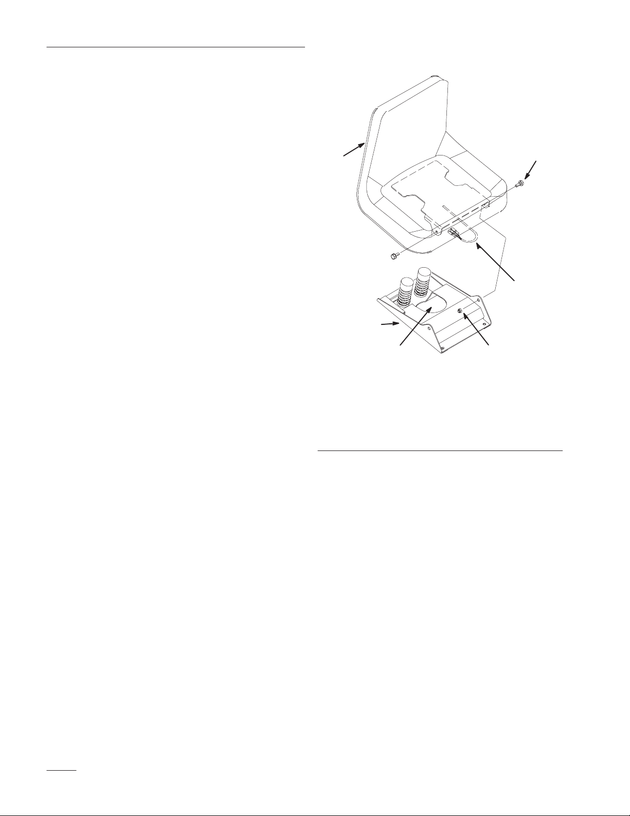
1. Mount the seat to the seat base using two 5/16”
shoulder bolts and lock nuts (Fig. 1).
2. Insert the seat switch wire through the center
opening in the seat base (Fig 1).
3. Push the seat switch wire connector into the wire
harness connector.
1
2
6
1. Seat
2. Seat base
3. 5/16” shoulder bolt (2)
4. 5/16” Locknut (4)
3
5
4
m–3453
Figure 1
5. Seat switch wire
connector
6. Opening for seat switch
wire
2
Page 3
Installing the Steering Wheel
Set-Up Instructions
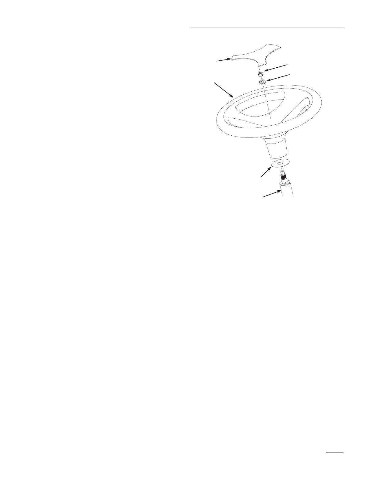
1. Install the boot washer onto the steering shaft
(Fig. 2).
2. Remove the plastic trim cover from the steering
wheel (Fig. 2)
3. Install the steering wheel onto the shaft,
carefully aligning the splines (Fig. 2).
Note: There is no fixed straight ahead
position on power steering models.
4. Secure the steering wheel to the shaft with a lock
washer and nut
(Fig. 2). Tighten the retaining nut
to 45–50 ft–lbs.
5. Install the trim cover on the steering wheel.
6
3
1. Boot washer
2. Steering shaft
3. Steering wheel
5
4
1
2
m–2482
Figure 2
4. Lock washer
5. Nut
6. Trim cover
3
Page 4

Set-Up Instructions
Checking Front Wheel Toe–In
1. With the tractor on a level surface, check to
make sure the front wheel toe-in is between 1/8”
and 1/4”. For instructions on adjusting toe-in,
refer to the Maintenance section in Operator’s
Manual.
Checking Tire Pressure
Check front and rear tire pressure. The correct front
and rear tire pressure is 12 psi (82.7 kPa).
4
Page 5

Activating the Battery
POTENTIAL HAZARD
• Battery electrolyte contains sulfuric acid
which is a deadly poison and it causes
severe burns.
Set-Up Instructions
2
WHAT CAN HAPPEN
• If you carelessly drink electrolyte you could
die or if it gets onto your skin you will be
burned.
HOW TO AVOID THE HAZARD
• Do not drink electrolyte and avoid contact
with skin, eyes or clothing. Wear safety
glasses to shield your eyes and rubber
gloves to protect your hands.
• Fill the battery where clean water is always
available for flushing the skin.
• Follow all instructions and comply with all
safety messages on the electrolyte container.
1. Remove the battery from the tractor (refer to
Removing the Battery in your tractor Operator’s
Manual).
Note: Never fill the battery electrolyte with
the battery installed in the tractor.
2. Remove the cell cover from the battery. Slowly
pour electrolyte into each cell until the
electrolyte level is up to the lower part of the
tube (Fig. 3). Use an electrolyte with a specific
gravity of 1.265.
1
3
m–3799
Figure 3
1. Cell cover
2. Electrolyte
3. Lower part of tube
POTENTIAL HAZARD
• Charging battery produces gasses.
WHAT CAN HAPPEN
• Battery gasses can explode.
HOW TO AVOID THE HAZARD
• Keep cigarettes, sparks and flames away
from battery.
3. Leave the cell cover off and connect a 3–4 amp
battery charger to the battery posts (Fig. 4).
Charge the battery at a rate of 4 amperes or less
for 4 hours (12 volts).
5
Page 6

Set-Up Instructions
4. When the battery is fully charged, unplug the
charger from electrical outlet, then disconnect
the charger leads from the battery posts (Fig. 4).
4
2
3
1
Figure 4
1. Positive battery post
2. Negative battery post
3. Red (+) charger lead
4. Black (–) charger lead
m–3798
Installing the Drawbar Hitch
Pin
Insert the drawbar hitch pin into the drawbar hitch
and secure it with a .50” I.D. flat washer and hairpin
cotter (Fig. 5).
1
1. Drawbar hitch pin
2. Drawbar hitch
2
4
Figure 5
3. .50” Flat washer
4. Hairpin cotter
3
m–2481
5. Slowly pour electrolyte into each cell until the
level is once again up to the lower part of the
tube (Fig. 3), then install the cell cover.
6. Install the battery in the tractor and connect the
battery cables (refer to Installing the Battery in
your tractor Operator’s Manual).
Note: Do not run the tractor with the battery
disconnected.
6
Page 7

Set-Up Instructions
Checking the Wiring and
Fasteners
• Inspect the tractor for any loose electrical
connections and secure them as required. Check
the wire routing to make sure moving parts do
not interfere with wires and cause a short.
• Assure all fasteners are tight.
Burnishing the Clutch
The following break–in procedure must be performed
as part of predelivery service or when a new clutch is
installed.
Note: There must be a PTO driven
attachment installed to provide a load
in order to burnish the clutch facings
properly.
1. Run the engine at full throttle and engage the
clutch bringing the load to full speed. Then
disengage the clutch.
2. Let the load come to a full stop, then engage
again.
3. Repeat these procedures (1 and 2) 5 times.
7
Page 8

Set-Up Instructions
Test Driving the Tractor
1. Check the oil level in the crankcase (refer to
Engine Oil in your tractor Operator’s Manual for
oil type, viscosity and crankcase capacity).
2. Check the oil level in the transaxle (refer to
Transaxle Fluid in your tractor Operator’s
Manual for oil type, viscosity and capacity).
3. Check that the coolant level is between the two
lines on the coolant recovery tank when the
engine is cold (refer to Check the Cooling
System in your tractor Operator’s Manual).
4. Make sure all water is drained from the fuel filter
(refer to Draining Water From The Fuel
Filter/Water Separator in your tractor Operator’s
Manual).
5. Check to make sure all lubrication points have
been greased as shown in the Maintenance
section of tractor Operator’s Manual.
6. Fill the tank with fresh diesel fuel with a
minimum cetane rating of 40 and the proper
grade for the ambient temperature conditions
(refer to Adding Fuel in your tractor Operator’s
Manual) Open the fuel shutoff valve and check
the fuel hose and fittings for leaks.
7. As applicable, check and test the operation of the
following:
• Engine and throttle controls
• Gauges
• Headlights and taillights
• Indicator lights
• PTO clutch and brake
• Lift system
• Service and parking brakes
• Transmission controls
• Steering
• Tractor operation in forward and reverse
8. Test the operation of the safety interlock system
(refer to the tractor Operator’s Manual for the
correct procedure).
8
 Loading...