

Page 1

KAWASAKI FD620D 4-STROKE LIQUID COOLED ENGINE SERVICE MANUAL
Table of Contents – Page 1 of 2
GENERAL INFORMATION
BEFORE SERVICING
MODEL IDENTIFICATION
GENERAL SPECIFICATIONS
PERIODIC MAINTENANCE CHART EXCEPT U.S.
PERIODIC MAINTENANCE CHART FOR U.S.
TORQUE AND LOCKING AGENT
FUEL SYSTEM
EXPLODED VIEW
SPECIFICATIONS
GOVERNOR LINK MECHANISM
CARBURETOR
INTAKE MANIFOLD
FUEL PUMP
AIR CLEANER
COOLING SYSTEM
EXPLODED VIEW
SPECIFICATIONS
COOLING SYSTEM
COOLANT
DISASSEMBLY AND ASSEMBLY PRECAUTIONS
WATER PUMP
RADIATOR
COOLING FAN, FAN BELT
THERMOSTAT
THERMO SWITCH
ENGINE TOP END
EXPLODED VIEW
SPECIFICATIONS
SPECIAL TOOLS
CYLINDER HEAD
VALVES
CYLINDER, PISTON
MUFFLER
LUBRICATION SYSTEM
EXPLODED VIEW
ENGINE OIL FLOW CHART
SPECIFICATIONS
ENGINE OIL AND OIL FILTER
PRESSURIZED LUBRICATION SYSTEM
OIL PUMP AND RELIEF VALVE
OIL SCREEN FILTER
Page 2

KAWASAKI FD620D 4-STROKE LIQUID COOLED ENGINE SERVICE MANUAL
Table of Contents – Page 2 of 2
CAMSHAFT / CRANKSHAFT
EXPLODED VIEW
SPECIFICATIONS
CRANKCASE
BREATHER
CAMSHAFT TAPPET
CRANKSHAFT, CONNECTING ROD
ELECTRICAL SYSTEM
EXPLODED VIEW
SPECIFICATIONS
SPECIAL TOOLS
WIRING DIAGRAM
WIRE HARNESS
PRECAUTIONS
CHARGING SYSTEM
IGNITION SYSTEM
ELECTRIC STARTER SYSTEM
TROUBLESHOOTING
ENGINE TROUBLESHOOTING GUIDE
STARTER MOTOR TROUBLESHOOTING GUIDE
Page 3
*y
4-stroke liquid-cooled v-twin gasoline engine
Service Manual
Page 4
O-l
Kawasaki
FD62QD
4-stroke liquid cooled v-twin gasoline engine
Service Manual
All rights reserved. No parts of this publication may be reproduced, stored in a retrieval system, or transmitted
in any form or by any means, electronic mechanical photocopying, recording or otherwise, without the prior
written permission of Quality Assurance Department/Consumer Products Group/Kawasaki Heavy Industries,
Ltd., Japan. .’
No liability can be accepted for any inaccuracies or omissions in this publication, although every possible care
has been taken to make it as complete and accurate as possible.
The right is reserved to make changes at any time without prior notice and without incurring an obligation to
make such changes to products manufactured previously.
All information contained in this publication is based on the latest product information available at the time
of publication. Illustrations and photographs in this publication are intended for reference use only and may not
depict actual model component parts.
0 Kawasaki Heavy Industries. Ltd. 1996
Second Edition(l) : Jan. 20,1996(T)
-
Page 5
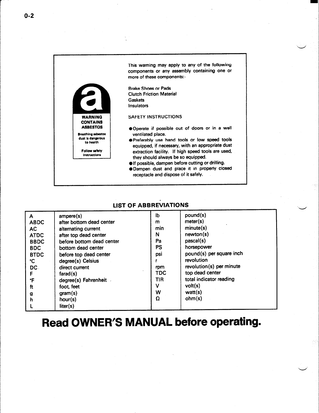
o-2
This warning may apply to any of the following
components or any assembly containing one or
more of these components:-
Brake Shoes or Pads
Clutch Friction Material
Gaskets
Insulators
Emthing rbmto~
dust is dm~rous
instructionr
A ampere(s)
ABDC
AC
ATDC
BBDC
BDC
BTDC
‘C
DCF
after bottom dead center
alternating current
after top
dead center
before bottom dead center
bottom dead center
before top dead center
degree(s) Celsius
direct current
farad(s)
‘F degree(s) Fahrenheit ,
ft
9 gram(s)
h
L
foot, feet
hour(s)
liter(s)
1
SAFETY INSTRUCTIONS
l
Operate if possible out of doors or in a well
ventilated place.
l
Preferably use hand tools or low speed tools
equipped, if necessary, with an appropriate dust
extraction facility. If high speed tools are used,
they should always be so equipped.
l
lf possible, dampen before cutting or drilling.
@Dampen dust and place it in properly closed
receptacle and dispose of it safely.
LIST OF ABBRE(/IATIONS
lb
m
min
N
Pa
PS
psi
r
rpm
TDC
TIR
v
W
n
pound(s)
meter(s)
minute(s)
newton(s)
Pascal(s)
horsepower
pound(s) per square inch
revolution
revolution(s) per minute
top dead center
total indicator reading
volt(s)
watt(s)
ohm(s)
Read OWNER’S MANUAL before operating.
Page 6
Foreword
m
o-3
This manual is designed primarily for use by
trained mechanics in a properly equipped shop.
However, it contains enough detail and basic
information to make it useful to the owner who
desires to perform his own basic maintenance and
repair,work. A basic knowledge of mechanics, the
proper use of toofs, and workshop procedures must
be understood in order to carry out maintenance and
‘repair satisfactorily.
insufficient experience or has doubts as to his ability
to do the work, all adjustments, maintenance, and
repair should be carried out only by qualified
mechanics.
In order to perform the work efficiently and to
avoid costly mistakes, read the text, thoroughly
familiarize yourself with the procedures before
starting work, and then do the work carefully in a
clean area. Whenever special tools or equipment are
specified, do not use makeshift tools or equipment.
Precision measurements can only be made if the
proper instruments are used, and the use of substitute tools may adversely affect safe operation.
To get the longest life out of your engine:
l
Follow the Periodic Maintenance Chart in the
Service Manual.
l
Be alert for problems and non-scheduled mainte-
nance.
l
Use proper tools and genuine Kawasaki engine
parts. Genuine parts provided as spare parts are
listed in the Parts Catalog.
l
FOIIOW the procedures in this manual carefully.
Don’t take shortcuts.
*Remember to keep complete records of mainte-
nance and repair with dates and any new parts
installed.
Whenever the owner has
How to Use this Manual
In preparing this manual, we divided the product
into its major systems. These systems became the
manual’s chapters. All information for a particular
system from adjustment through disassembly and
inspection is located in a single chapter.
The Quick Reference Guide shows you all of the
product’s system and assists in locating their
chapters. Each chapter in turn has its own comprehensive Table of Contents.
The Periodic Maintenance Chart is located in the
General Information chapter. The chart gives a time
schedule for required maintenance operations.
If you want spark plug information, for example,
go to the Periodic Maintenance Chart first. The chart
tells you how frequently to clean and gap the plug.
Next, use the Quick Reference Guide to locate the
electric System chapter. Then, use the Table of
Contents on the first page of the chapter to find the
Spark Plug section.
Whenever you see these WARNING and
CAUTION symbols, heed their instructions! Always
follow safe operating and maintenance practices.
This warning symbol identifies special
instructions or procedures which, if not
correctly followed, could result in personal
injury, or loss of life.
ACAUTION
This caution symbol identifies special
instructions or procedures which, if not
strictly observed, could result in damage to
or destruction of equipment.
Page 7
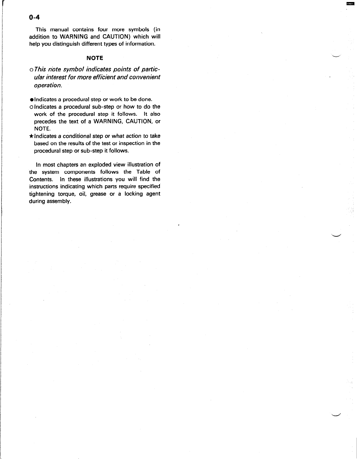
This manual contains four more symbols (in
addition to WARNING and CAUTION) which will
help you distinguish different types of information.
I
NOTE
o This note symbol indicates points of partic-
ular interest for more efficient and convenient
operation.
l
Indicates a procedural step or work to be done.
olndicates a procedural sub-step or how to do the
work of the procedural step it follows. It also
precedes the text of a WARNING, CAUTION, or
NOTE.
*Indicates a conditional step or what action to take
based on the results of the test or inspection in the
procedural step or sub-step it follows.
In most chapters an exploded view illustration of
the system components follows the Table of
Contents.
instructions indicating which parts require specified
tightening torque, oil, grease or a locking agent
during assembly.
In these illustrations you will find the
Page 8
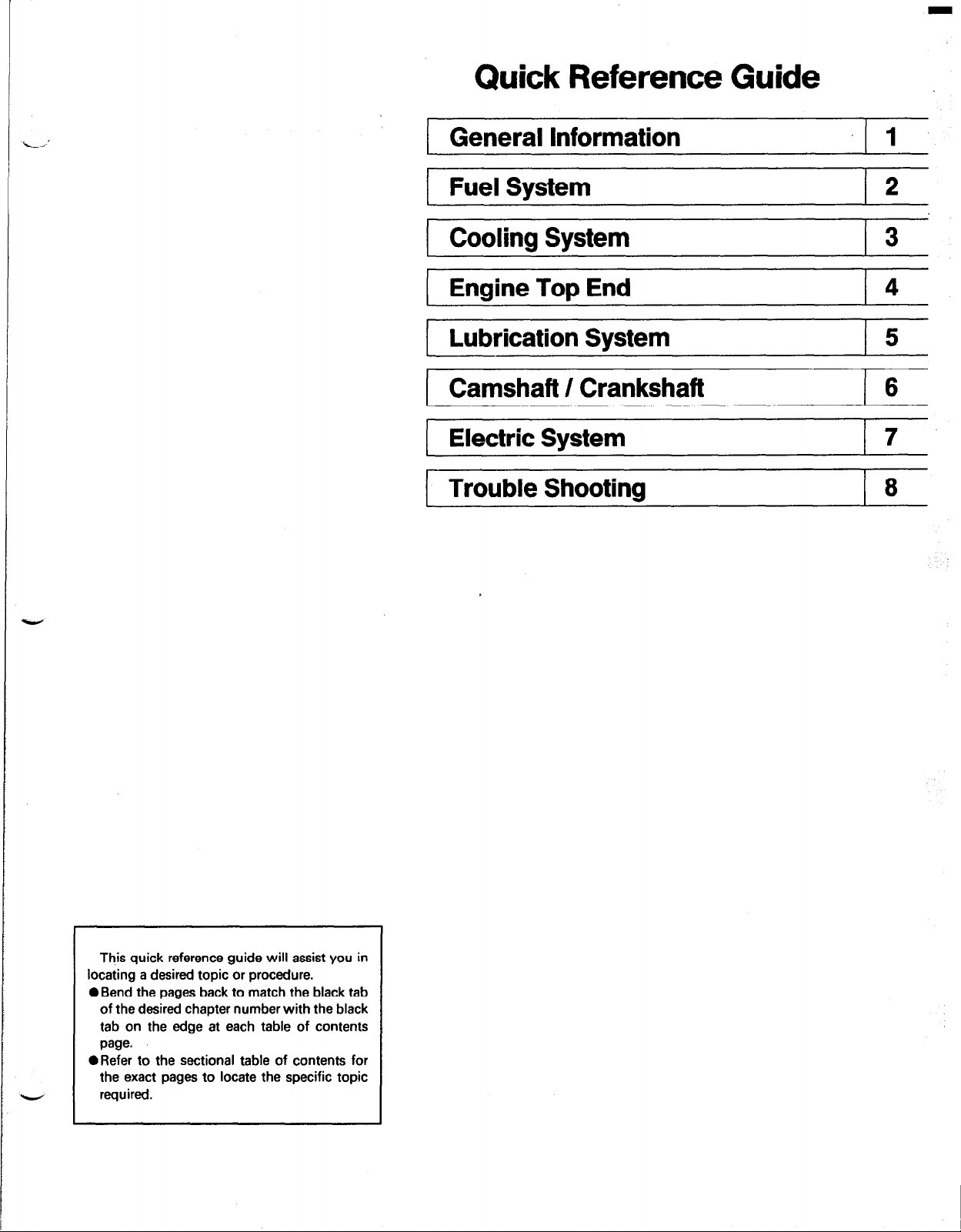
Quick Reference Guide
1 General Information I 1
1 Fuel System
( Cooling System
1 Engine Top End
Lubrication System ( 5
I
( Camshaft / Crankshaft
1 Electric System
I Trouble Shooting
I 2
I 3
This quick reference guide will assist you in
locating a desired topic or procedure.
0 Bend the pages back to match the black tab
of the desired chapter number with the black
tab on the edge at each table of contents
page.
l
Refer to the sectional table of contents for
the exact pages to locate the specific topic
-
required.
Page 9
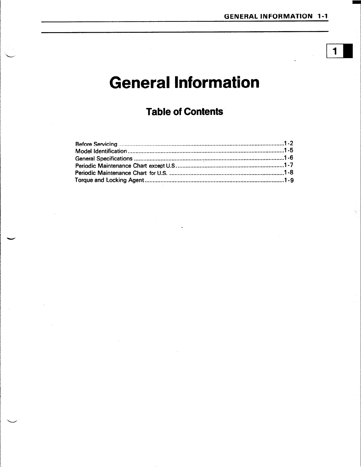
GENERAL INFORMATION l-l
General Information
Table of Contents
1
II
Before Servicing .........................................................................................................
Model Identification ....................................................................................................
General Specifications
Periodic Maintenance Chart except U.S
Periodic Maintenance Chart for
Torque and Locking Agent.. ......................................................................................
............................................
......................................................................
U.S. ......................................................................... .1-B
. ................................................... l-6
.I -2
l-5
1-7
.l -9
Page 10
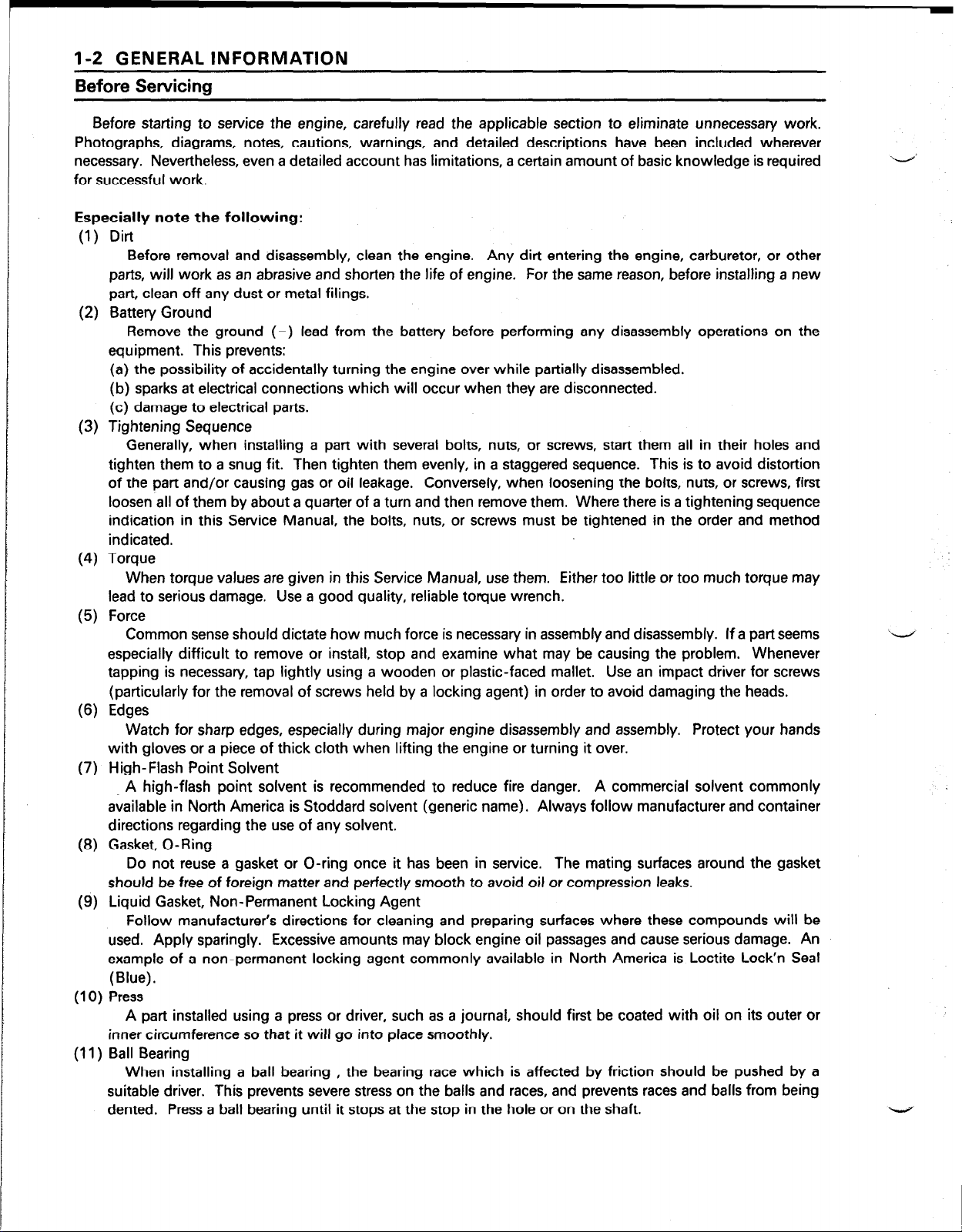
1-2 GENERAL INFORMATION
Before Servicing
Before starting to service the engine, carefully read the applicable section to eliminate unnecessary work.
Photographs, diagrams, notes, cautions, warnings, and detailed descriptions have been included wherever
necessary. Nevertheless, even a detailed account has limitations, a certain amount of basic knowledge is required
for successful work.
Especially note the following:
(1) Dirt
Before removal and disassembly, clean the engine. Any dirt entering the engine, carburetor, or other
parts, will work as an abrasive and shorten the life of engine.
part, clean off any dust or metal filings.
:) Battery Ground
(2
Remove the ground (-) lead from the battery before performing any disassembly operations on the
equipment. This prevents:
(a) the possibility of accidentally turning the engine over while partially disassembled.
(b) sparks at electrical connections which will occur when they are disconnected.
(c) damage to electrical parts.
(3) Tightening Sequence
Generally, when installing a part with several bolts, nuts, or screws, start them all in their holes and
tighten them to a snug fit. Then tighten them evenly, in a staggered sequence. This is to avoid distortion
of the part and/or causing gas or oil leakage. Conversely, when loosening the bolts, nuts, or screws, first
loosen all of them by about a quarter of a turn and then remove them. Where there is a tightening sequence
indication in this Service Manual, the bolts, nuts, or screws must be tightened in the order and method
indicated.
(4) Torque
When torque values are given in this Service Manual, use them. Either too little or too much torque may
lead to serious damage. Use a good quality, reliable torque wrench.
(5) Force
Common sense should dictate how much force is necessary in assembly and disassembly. If a part seems
especially difficult to remove or install, stop and examine what may be causing the problem. Whenever
tapping is necessary, tap lightly using a wooden or plastic-faced mallet. Use an impact driver for screws
(particularly for the removal of screws held by a locking agent) in order to avoid damaging the heads.
(6) Edges
Watch for sharp edges, especially during major engine disassembly and assembly. Protect your hands
with gloves or a piece of thick cloth when lifting the engine or turning it over.
(7) High-Flash Point Solvent
A high-flash point solvent is recommended to reduce fire danger. A commercial solvent commonly
available in North America is Stoddard solvent (generic name). Always follow manufacturer and container
directions regarding the use of any solvent.
(8) Gasket, O-Ring
Do not reuse a gasket or O-ring once it has been in service.
should be free of foreign matter and perfectly smooth to avoid oil or compression leaks.
(9) Liquid Gasket, Non-Permanent Locking Agent
Follow manufacturer’s directions for cleaning and preparing surfaces where these compounds will be
used. Apply sparingly. Excessive amounts may block engine oil passages and cause serious damage. An
example of a non-permanent locking agent commonly available in North America is Loctite Lock’n Seal
(Blue).
(10) Press
A part installed using a press or driver, such as a journal, should first be coated with oil on its outer or
inner circumference so that it will go into place smoothly.
(11) Ball Bearing
When installing a ball bearing , the bearing race which is affected by friction should be pushed by a
suitable driver. This prevents severe stress on the balls and races, and prevents races and balls from being
dented. Press a ball bearing until it stops at the stop in the hole or on the shaft.
For the same reason, before installing a new
The mating surfaces around the gasket
.-~
Page 11
GENERAL INFORMATION 1-3
(12) Oil Seal, Grease Seal
Replace any oil or grease seals that were removed with new ones, as removal generally damages seals.
When pressing in a seal which has manufacturer’s marks, press it in with the marks facing out. Seals
should be pressed into place using a suitable driver, which contacts evenly with the side of seal, until the
face of the seal is even with the end of the hole.
(13) Seal Guide
A seal guide is required for certain oil or grease seals during installation to avoid damage to the seal lips.
Before a shaft passes through a seal, apply a little oil, preferably high temperature grease on the lips to
reduce rubber to metal friction.
(14) Circlip, Retaining Ring
Replace any circlips and retaining rings that were removed with new ones, as removal weakens and
deforms them. When installing circlips and retaining rings, take care to compress or expand them only
enough to install them and no more.
(15) Cotter Pin
Replace any cotter pins that were removed with new ones, as removal deforms and breaks them.
(16) Lubrication
Engine wear is generally at its maximum while the engine is warming up and before all the rubbing
surfaces have an adequate lubricative film. During assembly, oil or grease (whichever is more suitable)
should be applied to any rubbing surface which has lost its lubricative film. Old grease and dirty oil should
be cleaned off. Deteriorated grease has lost its lubricative quality and may contain abrasive foreign particles.
Don’t use just any oil or grease. Some oils and greases in particular should be used only in certain
applications and may be harmful if used in an application for which they are not intended. This manual
makes reference to molybdenum disulfide grease (MO& ) in the assembly of certain engine parts. Always
check manufacturer recommendations before using such special lubricants.
(17) Electrical Wires
All the electrical wires are either single-color or two-color and, with only a few exceptions, must be
connected to wires of the same color. On any of the two-color wires there is a greater amount of one color
and a lesser amount of a second color, so a two-color wire is identified by first the primary color and then
the secondary color. For example, a yellow wire with thin red stripes is referred to as a “yellow/red” wire;
it would be a “red/yellow” wire if the colors were reversed to make red the main color.
-
Wire (cross-section)
Red
Wire Strands
Yellow
Red
(18) Replacement Parts
When there is a replacement instruction, replace these parts with new ones every time they are removed.
There replacement parts will be damaged or lose their original function once removed.
(19) Inspection
When parts have been disassembled, visually inspect these parts for the following conditions or other
damage. If there is any doubt as to the condition of them, replace them with new ones.
Abrasion Crack
Bent Dent Scratch
Color change Deterioration Seizure
(20) Specifications
Specification teams are defined as follows:
“Standards”: show dimensions or performances which brand-new parts or systems have.
“Service Limits” Indicate the usable limits. If the measurement shows excessive wear or deteriorated
performance, replace the damaged parts.
Name of Wire Color
I
Yellow/Red
Hardening Warp
I
Wear
Page 12
l-4 GENERAL INFORMATION
KAWASAKI Multimeter:
KAWASAKI Multimeter (P/N 3951 OO-9803A) is recommended for the electrical system check because a
meter of other type may indicate different value.
Page 13
Model Identification
GENERAL INFORMATION 1-5
Cylinder Number Designation:
No.1 Cyl. is the right-hand cylinder viewed from the flywheel.
No.2 Cyl. is the left-hand cylinder viewed from the flywheel.
Page 14
1-6 GENERAL INFORMATION
General Specifications
Items
Type of engine
Bore x Stroke
Piston displacement
Max. output
Direction of rotation
Low idle speed except U.S.
Low idle speed for U.S.
High idle speed except U.S.
High idle speed for U.S.
Ignition system
RFI
Starting system
Charging system
Carburetor
Fuet pump
Air cleaner
Governor
Lubrication system
“Oil filter
‘Oil pressure switch
Cooling system
l
Radiator
Dimensions (H x W x L)
Dry weight 41.5 kg (91.5 lb)
Liquid-cooled, Horizontal shaft, OHV, 4-stroke, 9O”V-twin, Gasoline
engine.
76 mm x 68 mm (2.99 in x 2.66 in)
617 mL (37.7 cu. in)
14.9 kW/3 600 rpm (20 HP/3 600 rpm)[SAE J1349]
Counterclockwise facing PTO shaft end
1550 -?r 100 (rpm)
1450 (rpm) to 1650 (rpm)
3600 + 75(rpm)
3600 (rpm)
Battery, Full transister, Fixed timing
Per Canada and U.S.A. requirements
Shift type electric starter
12 V - 20 amps with regulator
Down draft type, Fixed main jet
Electra magnetic pump (in-line type)
Dual stage element
All speed mechanical fly weights
Pressure feed by positive displacement pump
Cartridge type full flow filter
ON-OFF switch
Pressurized forced circulation type
3-rows with louverless corrugated fin
624 mm x 448 mm x 556 mm
(24.6 in x 17.6 in x 21.9 in)
FD620D
‘Specifications are subject to change without notice.
Page 15
GENERAL INFORMATION l-7
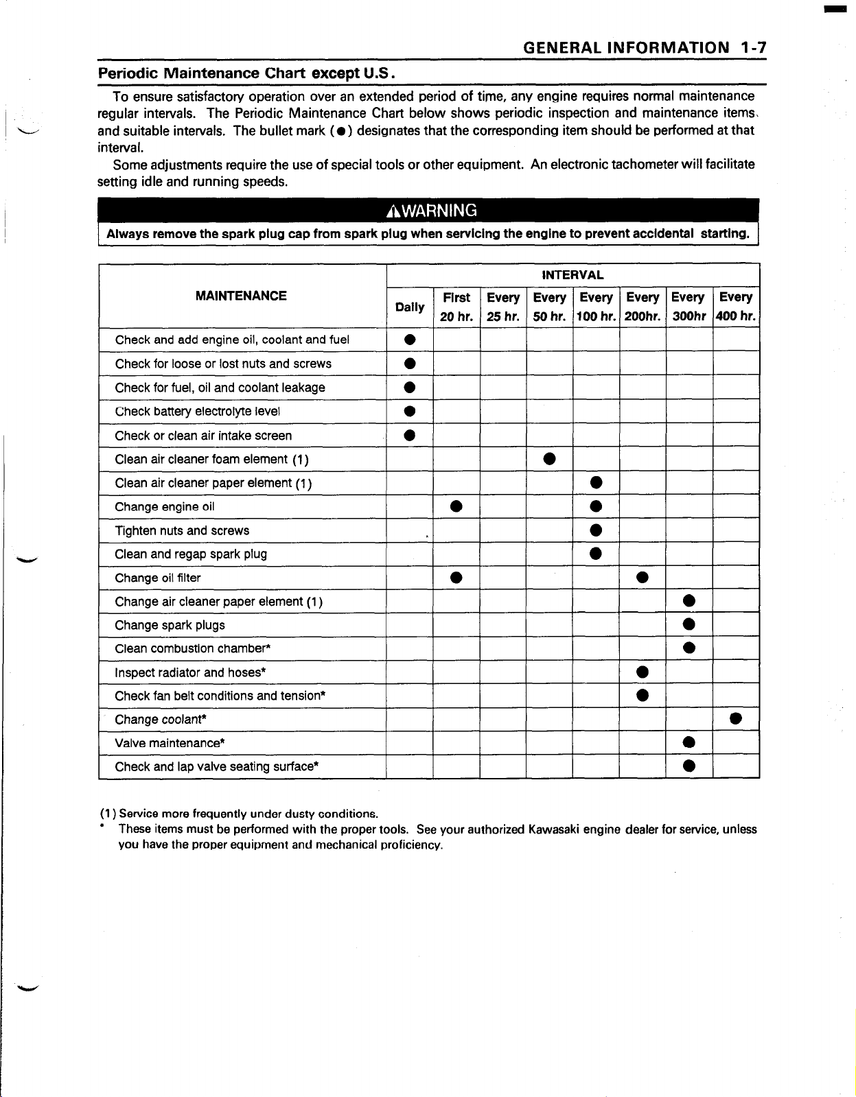
Periodic Maintenance Chart except U.S.
To ensure satisfactory operation over an extended period of time, any engine requires normal maintenance
regular intervals. The Periodic Maintenance Chart below shows periodic inspection and maintenance items\
and suitable intervals. The bullet mark (0) designates that the corresponding item should be performed at that
interval.
Some adjustments require the use of special tools or other equipment. An electronic tachometer will facilitate
setting idle and running speeds.
Always remove the spark plug cap from spark plug when servicing the engine to prevent accldental starting.
INTERVAL
MAINTENANCE
Check and add engine oil, coolant and fuel
Check for loose or lost nuts and screws
Check for fuel, oil and coolant leakage
Check battery electrolyte level
Check or clean air intake screen
Clean air cleaner foam element (1)
Clean air cleaner paper element (I )
Change engine oil
Tighten nuts and screws
Clean and regap spark plug
Change oil filter
Change air cleaner paper element (1)
Change spark plugs
Clean combustion chamber*
Inspect radiator and hoses*
Check fan belt conditions and tension*
Change coolant*
Valve maintenance*
I
Check and lap valve seating surface*
Dally
I I I
I I I I I I
First Every Every Every Every Every Every
20 hr. 25 hr. 50 hr. 100 hr. 200hr. 3OOhr 400 hr.
l
a
0
0
l
l
0
I 0 I I 0 I
( 0 1
0
0 0
0
0
l
l
l
l
I.1 I
( 0 )
I
(1) Service more frequently under dusty conditions.
l
These items must be performed with the proper tools. See your authorized Kawasaki engine dealer for service, unless
you have the proper equipment and mechanical proficiency.
Page 16
1-8 GENERAL INFORMATION
Periodic Maintenance Chart
To ensure satisfactory operation over an extended period of time, any engine requires normal maintenance
regular intervals. The Periodic Maintenance Chart below shows periodic inspection and maintenance items
and suitable intervals. The bullet mark (0) designates that the corresponding item should be performed at that
interval.
Some adjustments require the use of special tools or other equipment. An electronic tachometer will facilitate
setting idle and running speeds.
Always remove the spark plug cap from spark plug when servicing the engine to prevent accidental starting.
MAINTENANCE
for
U.S.
K Clean and lap valve seating surface
K Inspect radiator and hoses
K Check fan belt conditions and tension
K Change coolant
Note: The service intervals indicated are to be used as a guide. Service should be performed more frequently as
necessary by operating condition.
* : Service more frequently.under dusty conditions.
K : Have an authorized Kawasaki engine dealer perform those services.
0
0
0
0
Page 17
GENERAL INFORMATION l-9
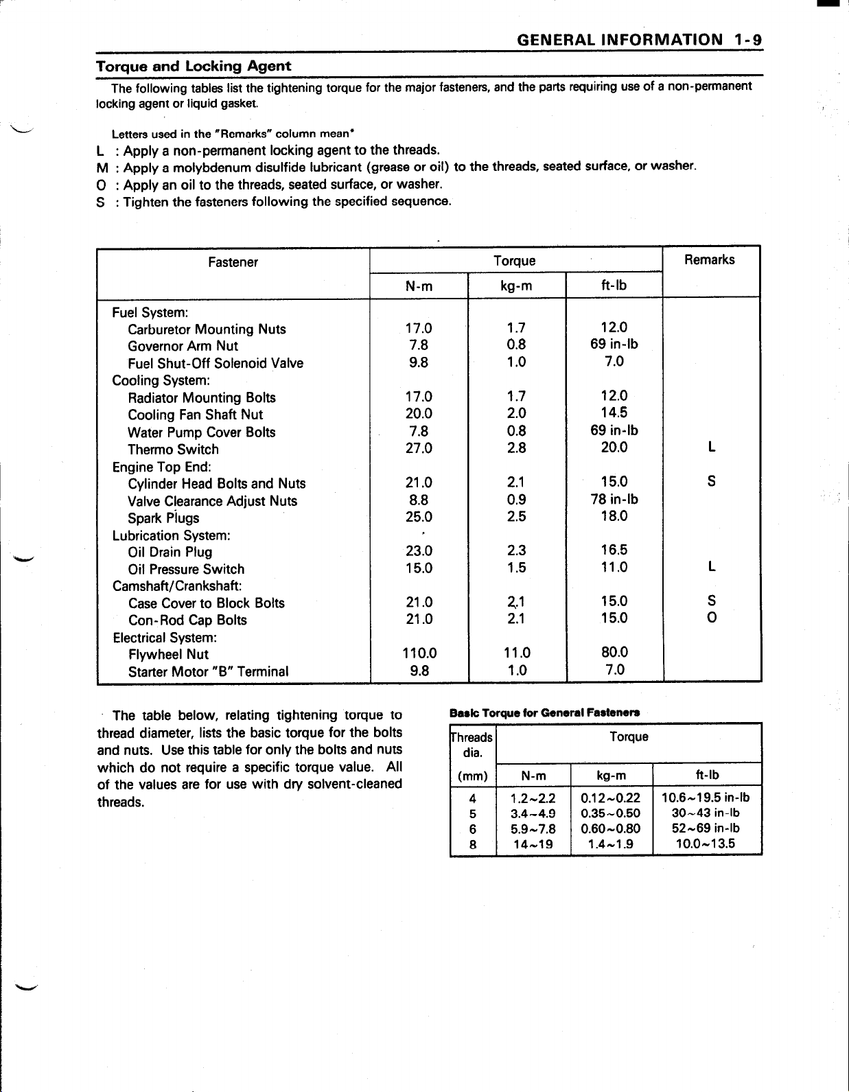
Torque and Locking Agent
The following tables list the tightening torque for the major fasteners, and the parts requiring use of a non-permanent
locking agent or liquid gasket.
L,
Letters used in the “Remarks” column mean*
L : Apply a non-permanent locking agent to the threads.
M : Apply a molybdenum disulfide lubricant (grease or oil) to the threads, seated surface, or washer.
0 : Apply an oil to the threads, seated surface, or washer.
S : Tighten the fasteners following the specified sequence.
Fastener
N-m
Torque Remarks
kg-m ft-lb
Fuel System:
Carburetor Mounting Nuts
Governor Arm Nut
Fuel Shut-Off Solenoid Valve
17.0
7.8
9.8
1.7
0.8
12.0
69 in-lb
1 .o 7.0
Cooling System:
Radiator Mounting Bolts
Cooling Fan Shaft Nut
Water Pump Cover Bolts
Therm0 Switch
17.0
20.0
7.8
27.0
1.7 12.0
2.0 14.5
0.8 69 in-lb
2.8 20.0
Engine Top End:
Cylinder Head Bolts and Nuts
Valve Clearance Adjust Nuts
Spark Piugs
21 .o
8.8
25.0
2.1 15.0
0.9 78 in-lb
2.5 18.0
Lubrication System:
Oil Drain Plug
Oil Pressure Switch
23.0
15.0
2.3
16.5
1.5 11 .o L
Camshaft/Crankshaft:
Case Cover to Block Bolts
Con-Rod Cap Bolts
21 .o
21 .o
2.1
15.0 S
2.1 15.0 0
Electrical System:
Flywheel Nut
Starter Motor “B” Terminal
110.0
9.8
11 .o 80.0
1 .o 7.0
L
S
The table below, relating tightening torque to
thread diameter, lists the basic torque for the bolts
and nuts. Use this table for only the bolts and nuts
which do not require a specific torque value. All
of the values are for use with dry solvent-cleaned
threads.
Bark Toraue for General Fasteners
hreads
dia.
(mm)
4 1.2-2.2
5 3.4-4.9
6 5.9-7.8
8 14-19
N-m
Torque
Page 18
Fuel System
Table of Contents
FUEL SYSTEM 2-l
2
L
Exploded View
Specifications..
Governor Link Mechanism
Control Panel Assembly/Removal
Control Panel Assembly Installation Notes
Governor Am, Removal
Governor Arm Installation
Governor Assembly Removal
Governor Assembly Installation Notes
Governor Assembly Inspection
Governor Shaft Removal
Governor Shaft Installation Notes
Carburetor
Fuel and Air Flow
Fuel Shut Off Solenoid Valve ..............................................................................................
Idle Mixture Screw (Pilot Screw) and Idle Speed Adjustment
Fast Idle Speed Adjustment..
High Altitude Operation
Main Jet Replacement..
Fuel System Cleanliness
Carburetor Removal
Installation Notes
Disassembly Assembly Notes ............................................................................................
Cleaning
Inspection..
Fuel Shut-Off Solenoid Valve Test
Intake Manifold..
Removal. ..............................................................................................................................
Installation Notes
inspection
Fuel Pump..
Fuel Pump Test ..................................................................................................................
Air Cleaner.. .......................................................................................................................... ...2-17
Element Removal.. ............................................................................................................. .2-l 7
Element Installation Notes..
Element Cleaning and Inspection
Cleaner Body and Bracket Removal
Cleaner Body and Bracket Installation Notes
Housing (Case and Body) Inspection
.......................................................................................................................... 2-2
.......................................................................................................................... 2-4
.......................................................................................................
.......................................................................................
........................................................................................................
....................................................................................................
...............................................................................................
............................................................................................
.....................................................................................................
......................................................................................
.................................................................................................................................. 2-8
.......................................... 0 ......................................................................
............................................................................................... 2-9
..................................................................................................... 2-10
..................................................................................................... 2-10
Inspection
........................................................................................................... 2-l 1
............................................................................................................... 2-l 1
............................................................................................................................. 2-12
......................................................................................................................... 2-l 3
....................................................................................
..................................................................................................................... 2-l 5
............................................................................................................... 2-l 5
.........................................................................................................................
.......................................................................................................................... ...2-16
...............................................................................................
......................................................................................
........................................................................
................................................................................
..........................................
.................................................................................. 2-l 1
................................................................................ ..2-18
.................................................................... 2-18
...............................................................................
2-5
2-5
.2-5
2-5
2-5
2-6
2-6
2-6
.2-6
.2-7
2-8
2-8
2-9
2-l 2
2-14
2-l 5
..2-15
2-16
2-17
2-17
2-18
Page 19
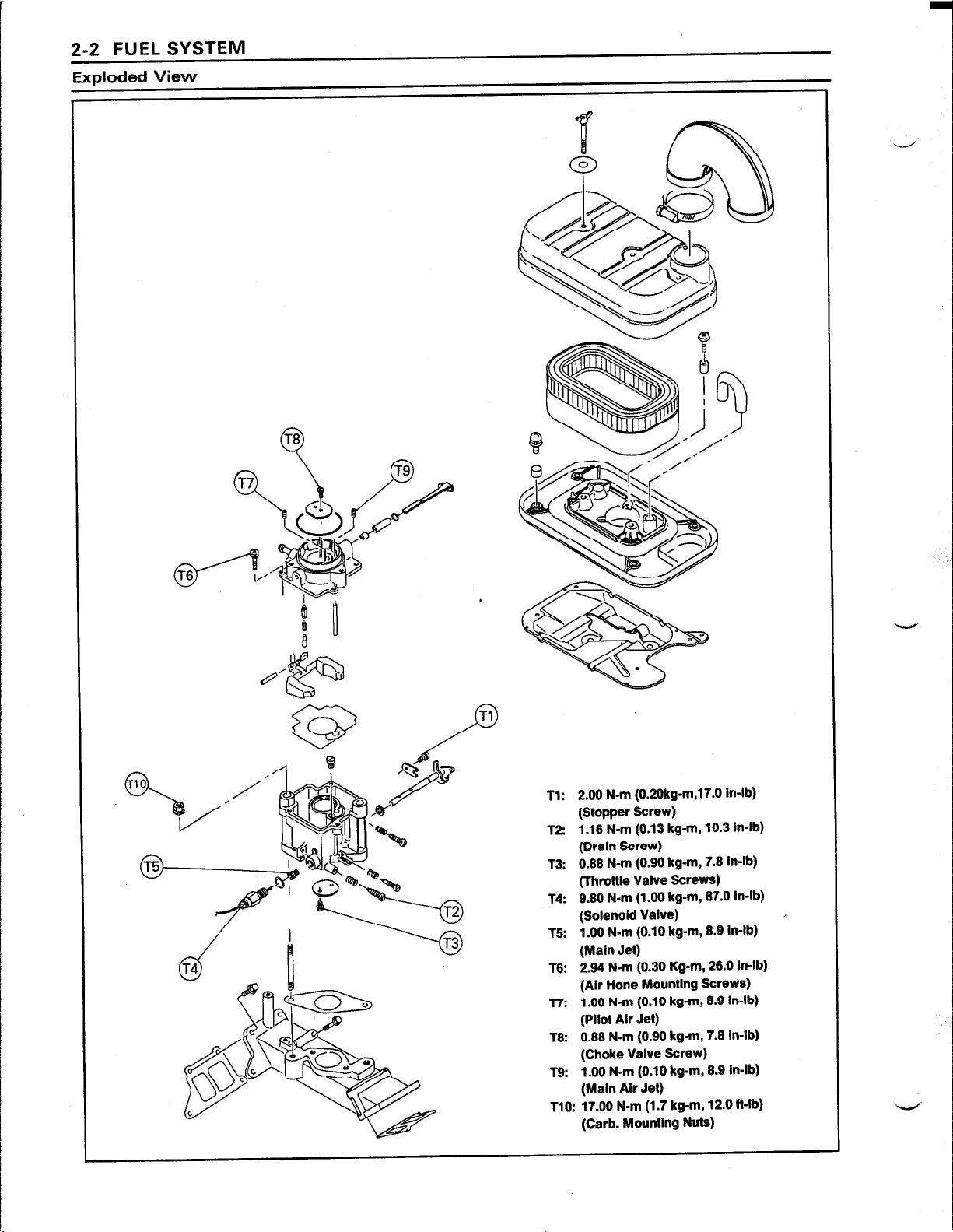
2-2 FUEL SYSTEM
Exploded View
Tl: 2.00 N-m (0.20kg-m,17.0 in-lb)
(Stopper Screw)
T2: 1.16 N-m (0.13 kg-m, 10.3 in-lb)
(Drain Screw)
T3: 0.66 N-m (0.90 kg-m, 7.6 in-lb)
(Throttle Valve Screws)
T4: 9.80 N-m (1 .OO kg-m, 87.0 In-lb)
(Solenoid Valve)
T5: 1.00 N-m (0.10 kg-m, 8.9 in-lb)
(Main Jet)
T6: 2.94 N-m (0.30 Kg-m, 26.0 In-lb)
(Air Hone Mounting Screws)
T7: 1.00 N-m (0.10 kg-m, 8.9 in-lb)
(Pilot Ah Jet)
T8: 0.88 N-m (0.90 kg-m, 7.8 in-lb)
(Choke Valve Screw)
l8: 1.00 N-m (0.10 kg-m, 8.9 in-lb)
(Main Air Jet)
TlO: 17.00 N-m (1.7 kg-m, 12.0 Mb)
(Carb. Mounting Nuts)
Page 20
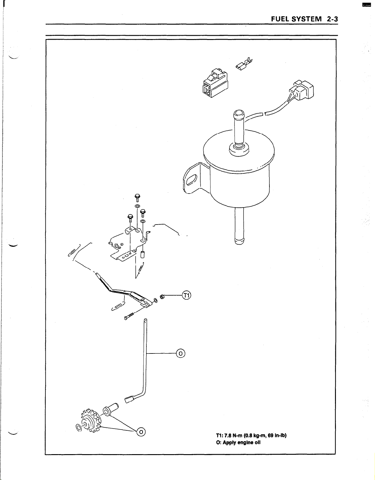
FUEL SYSTEM 2-3
.
4
Tl: 7.6 N-m (0.8 kg-m, 89 in-lb)
0: Apply engine oil
Page 21
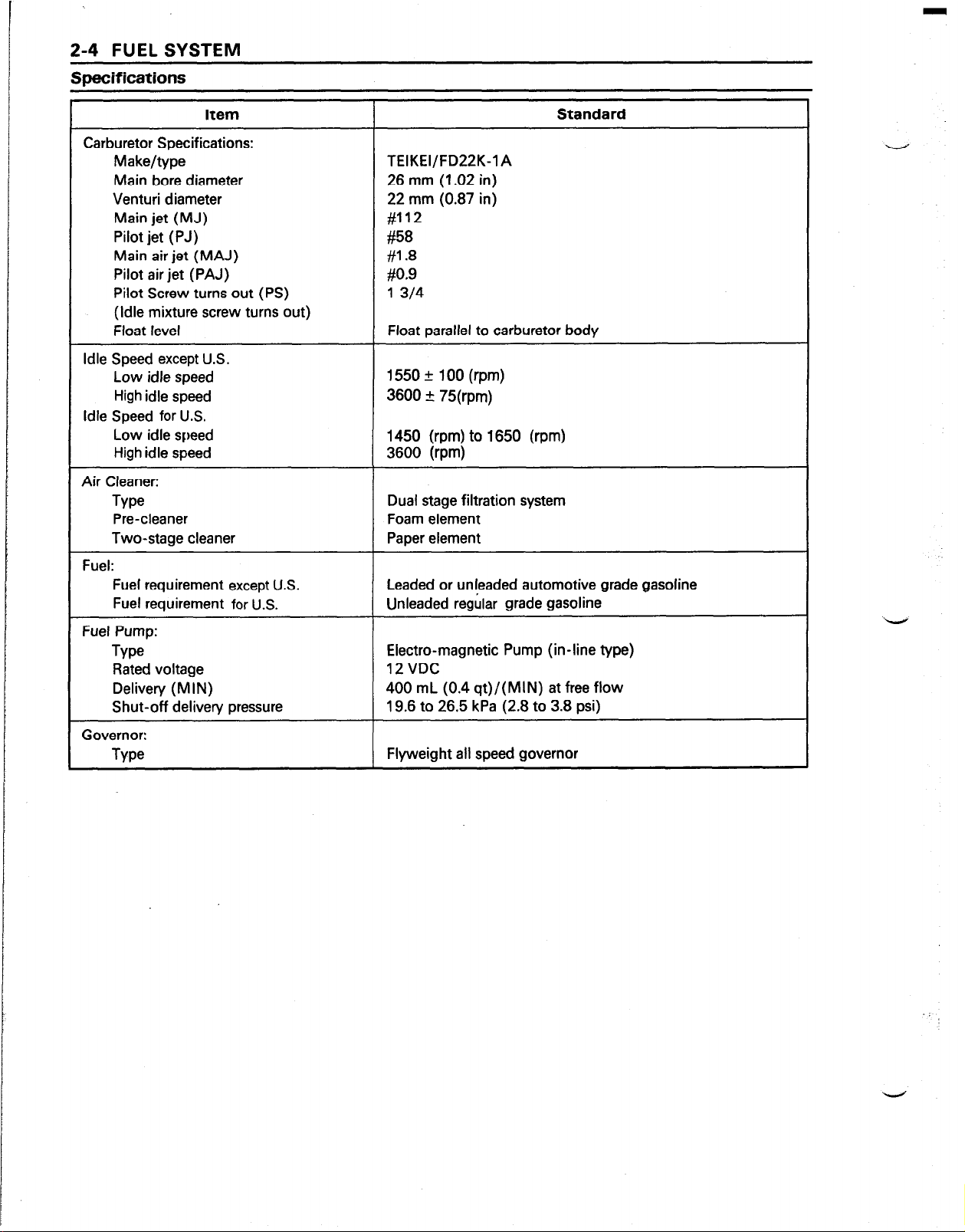
2-4 FUEL SYSTEM
Specifications
Item
Carburetor Specifications:
Make/type
Main bore diameter
Venturi diameter
Main jet (MJ)
Pilot jet (PJ)
Main air jet (MAJ)
Pilot air jet (PAJ)
Pilot Screw turns out (PS)
(Idle mixture screw turns out)
Float level
Idle Speed except U.S.
Low idle speed
High idle speed
Idle Speed for U.S.
Low idle speed
High idle speed
Air Cleaner:
Type
Pre-cleaner
Two-stage cleaner
Standard
TEIKEI/FD22K-1 A
26 mm (1.02 in)
22 mm (0.87 in)
#112
#58
#1.8
#0.9
1 314
Float parallel to carburetor body
1550 _+ 100 (rpm)
3600 a 75(rpm)
1450 (rpm) to 1650 (rpm)
3600 (rpm)
Dual stage filtration system
Foam element
Paper element
Fuel:
Fuel requirement except U.S.
Fuel requirement
Fuel Pump:
Type
Rated voltage
Delivery (MIN)
Shut-off delivery pressure
Governor:
Type
for U.S.
Leaded or unleaded automotive grade gasoline
Unleaded regular grade gasoline
Electra-magnetic Pump (in-line type)
12VDC
400 mL (0.4 qt)/(MIN) at free flow
19.6 to 26.5 kPa (2.8 to 3.8 psi)
Flyweight all speed governor
Page 22
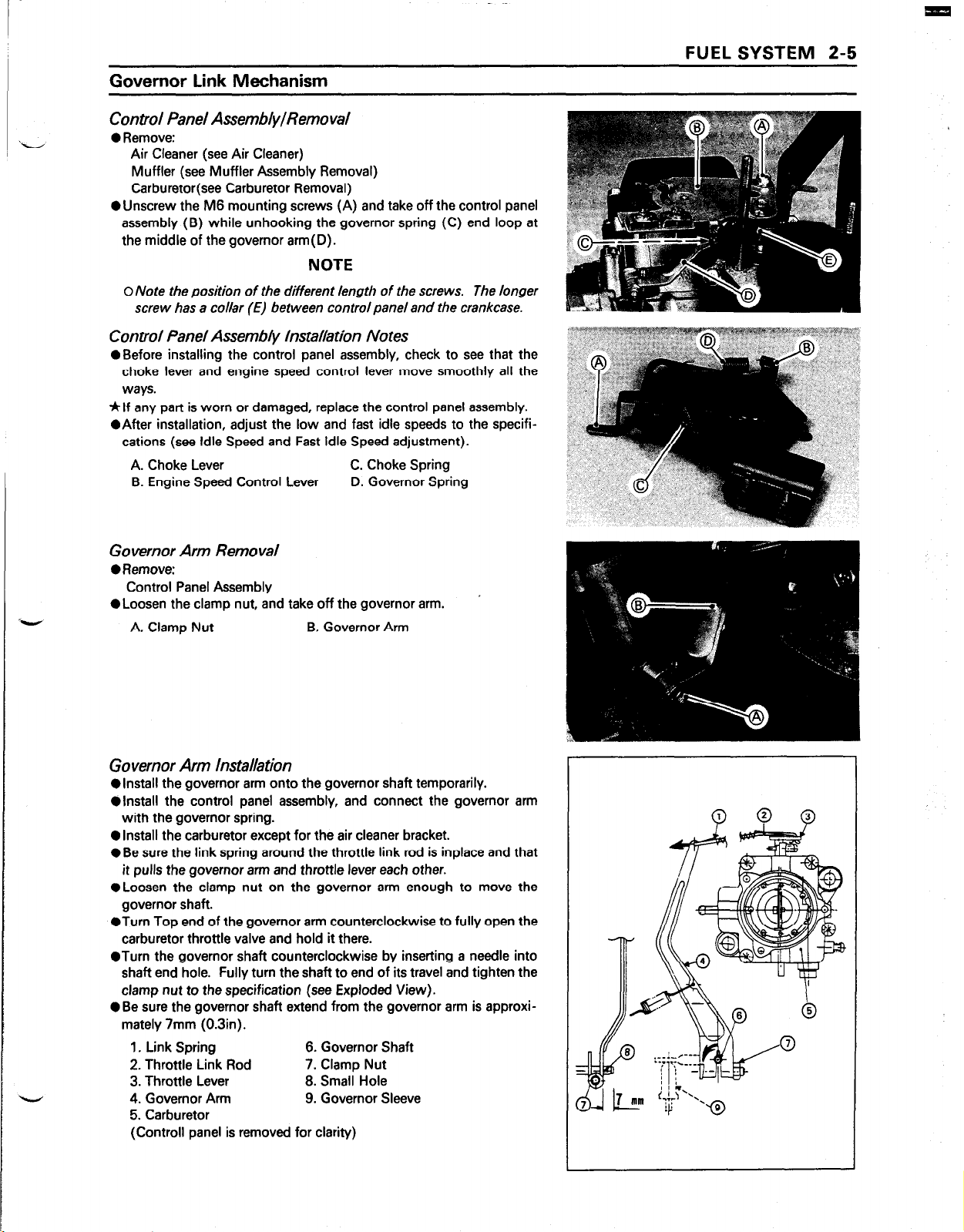
Governor Link Mechanism
Control Panel Assembly/Removal
0 Remove:
Air Cleaner (see Air Cleaner)
Muffler (see Muffler Assembly Removal)
Carburetor(see Carburetor Removal)
OUnscrew the M6 mounting screws (A) and take off the control panel
assembly (B) while unhooking the governor spring (C) end loop at
the middle of the governor arm(D).
NOTE
0 Note the position of the different length of the screws. The longer
screw has a collar (E) between control panel and the crankcase.
Control Panel Assembly Installation Notes
l
Before installing the control panel assembly, check to see that the
choke lever and engine speed control lever move smoothly all the
ways.
*If any part is worn or damaged, replace the control panel assembly.
l
After installation, adjust the low and fast idle speeds to the specifications (see Idle Speed and Fast Idle Speed adjustment).
A. Choke Lever C. Choke Spring
B. Engine Speed Control Lever D. Governor Spring
FUEL SYSTEM 2-5
Governor Arm Removal
0 Remove:
Control Panel Assembly
l
Loosen the clamp nut, and take off the governor arm.
A. Clamp Nut B. Governor Arm
Governor Arm Installation
l
install the governor arm onto the governor shaft temporarily.
l
install the control panel assembly, and connect the governor arm
with the governor spring.
0 Install the carburetor except for the air cleaner bracket.
l
Be sure the link spring around the throttle link rod is inplace and that
it pulls the governor arm and throttle lever each other.
l
Loosen the clamp nut on the governor arm enough to move the
governor shaft.
l
Turn Top end of the governor arm counterclockwise to fully open the
carburetor throttle valve and hold it there.
@Turn the governor shaft counterclockwise by inserting a needle into
shaft end hole. Fully turn the shaft to end of its travel and tighten the
clamp nut to the specification (see Exploded View).
l
Be sure the governor shaft extend from the governor arm is approximately 7mm (0.3in).
1. Link Spring 6. Governor Shaft
2. Throttle Link Rod 7. Clamp Nut
3. Throttle Lever 6. Small Hole
4. Governor Arm 9. Governor Sleeve
5. Carburetor
(Controll panel is removed for clarity)
Page 23
2-6 FUEL SYSTEM
Governor Assembly Removal
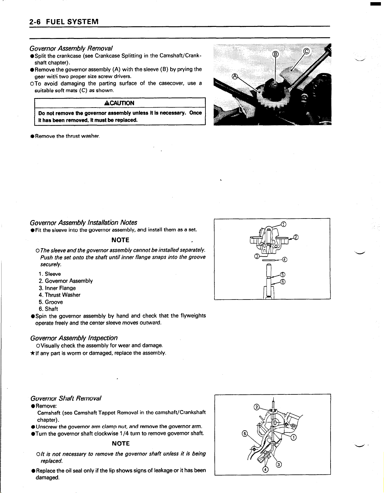
@Split the crankcase (see Crankcase Splitting in the Camshaft/Crank-
shaft chapter).
@Remove the governor assembly (A) with the sleeve (B) by prying the
gear with’ two proper size screw drivers.
OTo avoid damaging the parting surface of the casecover, use a
suitable soft mats (C) as shown.
ACAUTION
Do not remove the governor assembly unless it is necessary. Once
It has been removed, it must be replaced.
oRemove the thrust washer.
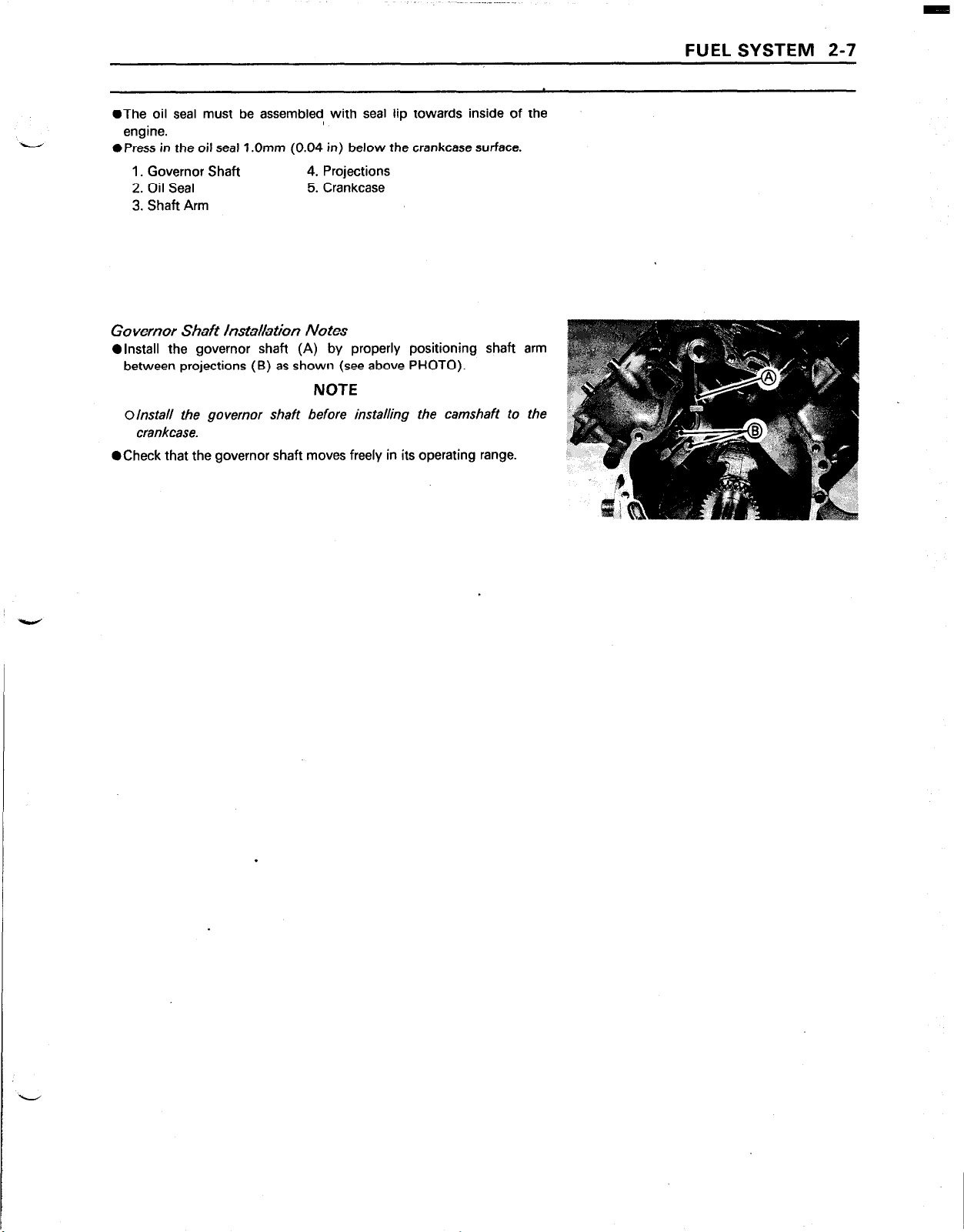
Governor Assembly Installation Notes
OFit the sleeve into the governor assembly, and install them as a set.
NOTE ,
0 The sleeve and the governor assembly cannot be installed separately.
Push the set onto the shaft until inner flange snaps into the groove
securely.
1. Sleeve
2. Governor Assembly
3. Inner Flange
4. Thrust Washer
5. Groove
6. Shaft
@Spin the governor assembly by hand and check that the flyweights
operate freely and the center sleeve moves outward.
Governor Assembly Inspection
OVisually check the assembly for wear and damage.
*If any part is worm or damaged, replace the assembly.
Governor Shaft Removal
0 Remove:
Camshaft (see Camshaft Tappet Removal in the camshaft/Crankshaft
chapter).
0 Unscrew the governor arm clamp nut, and remove the governor arm.
ofurn the governor shaft clockwise l/4 turn to remove governor shaft.
NOTE
O/t is not necessary to remove the governor shaft unless it is being
replaced.
0 Replace the oil seal only if the lip shows signs of leakage or it has been
damaged.
Page 24
l
The oil seal must be assembled, with seal lip towards inside of the
engine.
l
Press in the oil seal 1 .Omm (0.04 in) below the crankcase surface.
1. Governor Shaft
2. Oil Seal 5. Crankcase
3. Shaft Arm
4. Projections
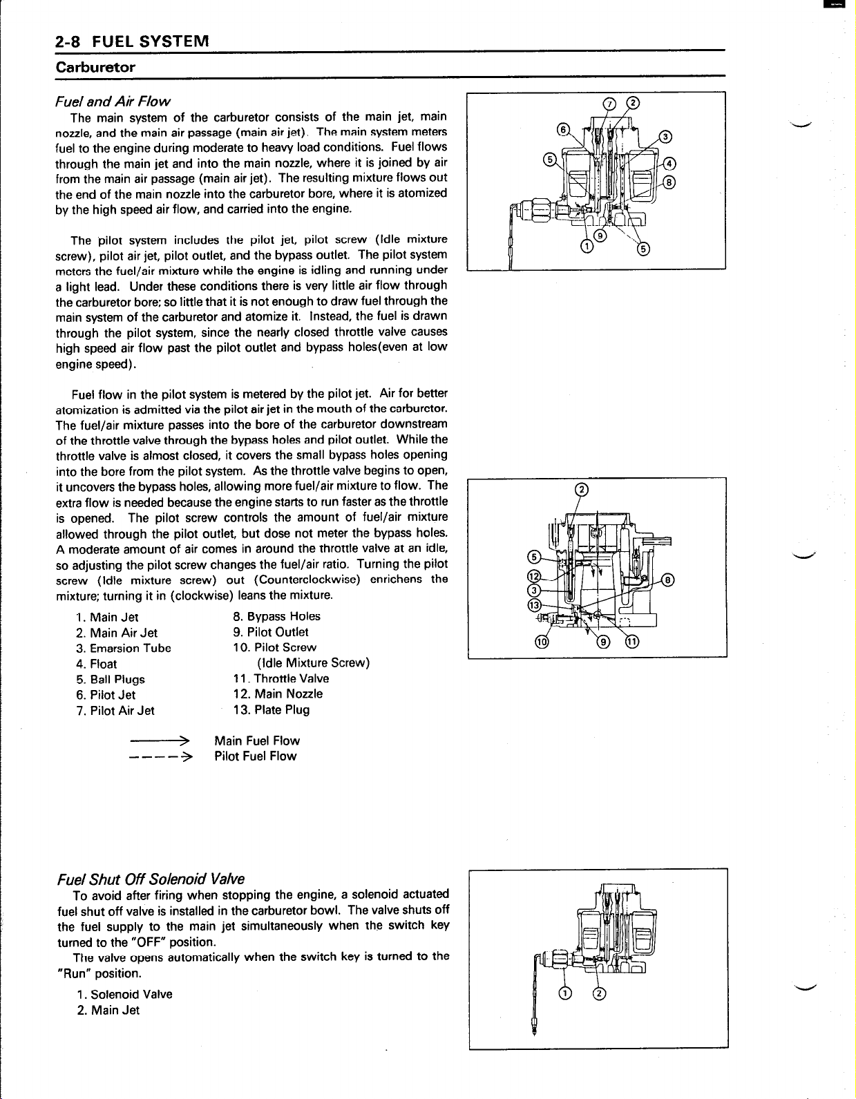
Governor Shaft Installation Notes
l
install the governor shaft (A) by properly positioning shaft arm
between projections (B) as shown (see above PHOTO).
NOTE
olnstall the governor shaft before installing the camshaft to the ‘>
crankcase.
l
Check that the governor shaft moves freely in its operating range.
FUEL SYSTEM 2-7
-
.
Page 25
2-8 FUEL SYSTEM
Carburetor
Fuel and Air Flow
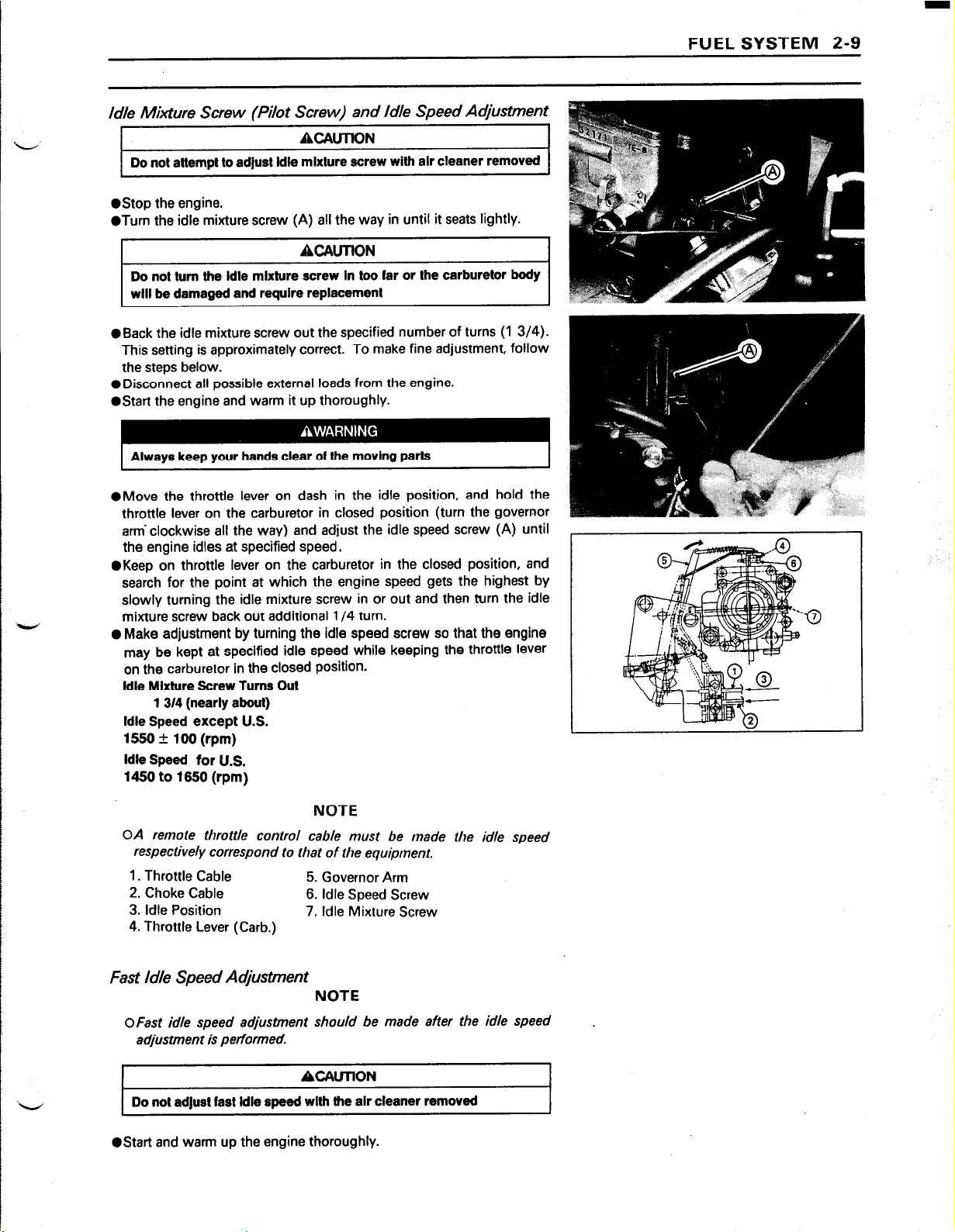
The main system of the carburetor consists of the main jet, main
nozzle, and the main air passage (main air jet). The main system meters
fuel to the engine during moderate to heavy load conditions. Fuel flows
through the main jet and into the main nozzle, where it is joined by air
from the main air passage (main air jet). The resulting mixture flows out
the end of the main nozzle into the carburetor bore, where it is atomized
by the high speed air flow, and carried into the engine.
The pilot system includes the pilot jet, pilot screw (Idle mixture
screw), pilot air jet, pilot outlet, and the bypass outlet. The pilot system
meters the fuel/air mixture while the engine is idling and running under
a light lead. Under these conditions there is very little air flow through
the carburetor bore; so little that it is not enough to draw fuel through the
main system of the carburetor and atomize it. Instead, the fuel is drawn
through the pilot system, since the nearly closed throttle valve causes
high speed air flow past the pilot outlet and bypass holes(even at low
engine speed).
Fuel flow in the pilot system is metered by the pilot jet. Air for better
atomization is admitted via the pilot air jet in the mouth of the carburetor.
The fuel/air mixture passes into the bore of the carburetor downstream
of the throttle valve through the bypass holes and pilot outlet. While the
throttle valve is almost closed, it covers the small bypass holes opening
into the bore from the pilot system. As the throttle valve begins to open,
it uncovers the bypass holes, allowing more fuel/air mixture to flow. The
extra flow is needed because the engine starts to run faster as the throttle
is opened. The pilot screw controls the amount of fuel/air mixture
allowed through the pilot outlet, but dose not meter the bypass holes.
A moderate amount of air comes in around the throttle valve at an idle,
so adjusting the pilot screw changes the fuel/air ratio. Turning the pilot
screw (Idle mixture screw) out (Counterclockwise) enrichens the
mixture; turning it in (clockwise) leans the mixture.
1. Main Jet 8. Bypass Holes
2. Main Air Jet 9. Pilot Outlet
3. Emarsion Tube 10. Pilot Screw
4. Float (Idle Mixture Screw)
5. Ball Plugs 11. Throttle Valve
6. Pilot Jet
7. Pilot Air Jet 13. Plate Plug
12. Main Nozzle
Main Fuel Flow
----
>
Pilot Fuel Flow
3
Fuel Shut Off Solenoid Valve
To avoid after firing when stopping the engine, a solenoid actuated
fuel shut off valve is installed in the carburetor bowl. The valve shuts off
the fuel supply to the main jet simultaneously when the switch key
turned to the “OFF” position.
The valve opens automatically when the switch key is turned to the
“Run” position.
1. Solenoid Valve
2. Main Jet
Page 26
Idle Mixture Screw (Pilot Screw) and Idle Speed AcQustment
ACAlJTtON
Do not attempt to adjust idle mixture screw with air cleaner removed
l
Stop the engine.
@Turn the idle mixture screw (A) all the way in until it seats lightly.
ACAlJTfON
Do not turn tfte idle mixture screw in too far or the carburetor body
will be damaged and require replacement
@Back the idle mixture screw out the specified number of turns (1 3/4).
This setting is approximately correct. To make fine adjustment, follow
the steps below.
l
Disconnect all possible external loads from the engine.
l
Start the engine and warm it up thoroughly.
FUEL SYSTEM 2-9
Always keep your hands clear of the moving
@Move the throttle lever on dash in the idle position, and hold the
throttle lever on the carburetor in closed position (turn the governor
arm clockwise all the way) and adjust the idle speed screw (A) until
the engine idles at specified speed.
l
Keep on throttle lever on the carburetor in the closed position, and
search for the point at which the engine speed gets the highest by
slowly turning the idle mixture screw in or out and then turn the idle
mixture screw back out additional l/4 turn.
0 Make adjustment by turning the idle speed screw so that the engine
may be kept at specified idle speed while keeping the
on the carburetor in the closed position.
idle Mixture Screw Turns Out
1 3/4 (nearly about)
idle Speed except U.S.
1550 + 100 (rpm)
idle Speed for U.S.
1450 to 1650 (rpm)
parts
throttle lever
NOTE
OA remote throttle control cable nlust be made the idle
respectively
1. Throttle Cable
2. Choke Cable
3. Idle Position
4. Throttle Lever (Carb.)
correspond to that of the equipment.
5. Governor Arm
6. Idle Speed Screw
7. Idle Mixture Screw
speed
Fast Idle Speed Ac#ustment
NOTE
OFast idle speed adjustment should be made after the idle speed
adjustment is performed.
ACAUllON
Do not adjust fast idle speed with the air cleaner removed
l
Start and warm up the engine thoroughly.
Page 27
2-10 FUEL SYSTEM
Always keep your hands clear of the moving parts.
l
Move the throttle lever on dash in the fast idle position and leave it
there.
@Loosen two M6 control panel mounting bolts enough to move the
control panel assembly.
l
Carefully move the control panel assembly left or right to obtain the
specified fast idle speed.
*Tighten the M6 Mounting bolts.
Fast Speed
3600 f 75 rpm
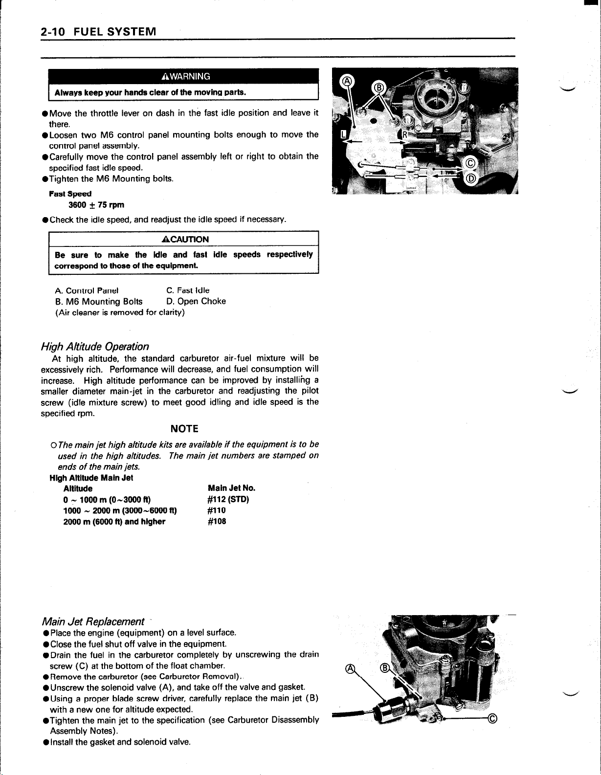
l
Check the idle speed, and readjust the idle speed if necessary.
ACAlJTlON
Be sure to make the idle and fast idle speeds respectively
correspond to those of the equipment.
A. Control Panel C. Fast Idle
B. M6 Mounting Bolts
(Air cleaner is removed for clarity)
D. Open Choke
High Altitude Operation
At high altitude, the standard carburetor air-fuel mixture will be
excessively rich. Performance will decrease, and fuel consumption will
increase. High altitude performance can be improved by installihg a
smaller diameter main-jet in the carburetor and readjusting the pilot
screw (idle mixture screw) to meet good idling and idle speed is the
specified rpm.
NOTE
0 The main jet high altitude kits are available if the equipment is to be
used in the high altitudes.
ends of the main jets.
High Altitude Main Jet
Altitude
0 y 1000 m (o-3000 ft)
1000 - 2000 m (3000 -6000 ft) #llO
2000 m (6000 ft) and higher #lOS
The main jet numbers are stamped on
Main Jet No.
#112 (STD)
Main Jet Replacement
l
Place the engine (equipment) on a level surface.
l
Close the fuel shut off valve in the equipment.
l
Drain the fuel in the carburetor completely by unscrewing the drain
screw (C) at the bottom of the float chamber.
ORemove the carburetor (see Carburetor Removal).
l
Unscrew the solenoid valve (A), and take off the valve and gasket.
@Using a proper blade screw driver, carefully replace the main jet (B)
with a new one for altitude expected.
@Tighten the main jet to the specification (see Carburetor Disassembly
Assembly Notes).
l
install the gasket and solenoid valve.
Page 28
f uef System Cleanliness inspection
Gasoline is extremely flammable and can be explosive under certain
conditions. Turn the ignition switch OFF. Do not smoke. Make sure
the area is well ventilated and free from any source of flame or
sparks; this includes any appliance with a pilot light.
l
Place a suitable drain hose (B) under the drain screw (A) on the
carburetor.
l
Run the lower end of the hose into a container.
l
Turn out the drain screw a few turns to drain the carburetor and check
to see if water or dirt has accumulated in the carburetor.
l
Tighten the drain screw.
*If any water or dirt come out, clean the carburetor (see carburetor
Cleaning), and fuel tank, and check the fuel filter.
FUEL SYSTEM 2-11
Carburetor Removal
Gasoline is extremely flammable and can be explosive under certain
conditions. Turn the ignition switch OFF. Do not smoke. Make sure
the area is well ventilated and free from any source of flame or
sparks; this includes any appliance with a pilot light.
0 Remove:
Air Cleaner and Related Parts (see Air Cleaner).
@Turn the fuel shut off valve to the OFF position.
0 Drain the carburetor.
0 Disconnect the fuel tube at the fuel inlet joint (A) of the carburetor.
0 Disconnect the solenoid valve lead terminal.
l
Unscrew the carburetor mounting nuts.
l
Unhook the throttle link spring (B) at the governor arm (C) top end
with a long nose plier.
l
Unhook the throttle and choke link rods (D.E) at the top ends of their
arms while lifting off the carburetor.
Installation Notes
l
Clean the mating surfaces of the carburetor and intake manifold and
fit a new gasket.
l
Take care not to bend the throttle and choke link rods during installation. Make sure the link spring around the throttle link rod is inplace
and that it pulls the governor arm and carburetor throttle lever toward
each other.
l
Adjust:
Carburetor Idle Mixture screw
Idle Speed
Page 29
2-12 FUEL SYSTEM
Disassembly Assembly Notes
@Refer to the illustration shown for disassembly and assembly.
@There are a number of the plate or boll plugs in the carburetor. None
of these should be removed.
@Turn in the idle mixture screw and count the number of turns until it
seats fully but not tightly, and then remove the screw. This is to set
the screw to its original position when assembling.
l
Turn the idle mixture screw all the way in until it seats lightly, and then
back it out the same number of turns counted during disassembly.
l
install the throttle valve on the shaft as the numerical mark on the valve
facing out side.
l
Note the metering hole in the choke valve, install the choke valve on
the shaft so that the metering hole towards fuel inlet joint of the
carburetor.
l
Drive in the float pin so that the pin extends the same distance on both
side of the float hinge bracket.
l
The fuel inlet valve seat is pressed into the carburetor body and is not
replaceable.
l
When assembling the carburetor parts which are attached to the
carburetor with the recommended tightening torque of a bolts and
screws. (see Exploded View)
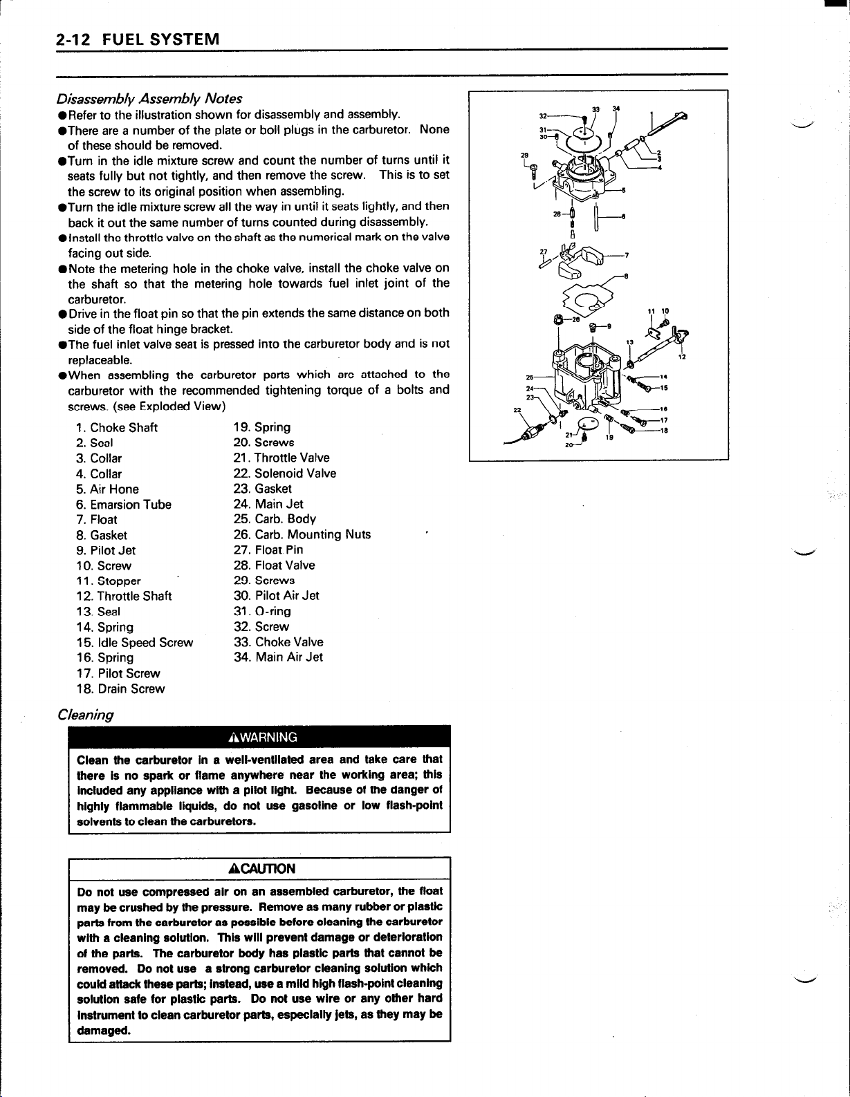
1. Choke Shaft 19. Spring
2. Seal 20. Screws
3. Collar
4. Collar 22. Solenoid Valve
5. Air Hone 23. Gasket
6. Emarsion Tube
7. Float 25. Carb. Body
8. Gasket 26. Carb. Mounting Nuts
9. Pilot Jet 27. Float Pin
10. Screw 28. Float Valve
11. Stopper 29. Screws
12. Throttle Shaft 30. Pilot Air Jet
13. Seal 31. O-ring
14. Spring
15. Idle Speed Screw 33. Choke Valve
16. Spring 34. Main Air Jet
17. Pilot Screw
18. Drain Screw
21. Throttle Valve
24. Main Jet
32. Screw
Cleaning
Clean the carburetor in a well-ventilated area and take care that
there is no spark or flame anywhere near the working area: this
Included any appliance wlth a pilot light. Because of the danger of
highly flammable liquids, do not use gasoline or low flash-point
solvents to clean the carburetors.
ACAUTION
Do not use compressed air on an assembled carburetor, the float
may be crushed by the pressure. Remove as many rubber or plastk
parts from the carburetor as possible before cleaning the carburetor
wltft a cleaning solution. This will prevent damage or deterloratkn
of the parts. The carburetor body has plastic parts that cannot be
removed. Do not use a strong carburetor cleaning solution which
could attack these parts; instead, use a mild high flash-point cleaning
solution safe for plastic parts. Do not use wire or any other hard
Instrument to clean carburetor parts, especially jets, as they may be
damaged.
Page 30
0 Disassemble the carburetor.
l
immerse all the carburetor metal parts in a carburetor cleaning solution
and clean them.
l
Rinse the carburetor parts in water and dry them with compressed air.
l
Do not use a rags or paper to dry parts. Lint may plug the holes or
passages.
0 Blow air through the holes and fuel passages with the compressed air.
All holes must be open.
l
Assemble the carburetor.
Inspection
Gasoline is extremely flammable and can be explosive under certain
Turn the lgnilion switch OFF. Do not smoke. Make sure the area Is
well ventilated and free from any source of flame or sparks; this
includes any appliance with a pilot light.
*Inspect the carburetor body for damage. Flange sealing surfaces
should be smooth and free of burrs and nicks. Replace the gasket if
necessary.
l
Turn the throttle and choke shafts to check that the throttle and choke
butterfly valves move smoothly.
*If the valves do not more smoothly, replace the carburetor body and/or
throttle shaft and choke shaft assembly.
l
Check that the gasket on the carburetor body.
*if the gasket is not in good condition, replace it.
l
Check the other parts of the carburetor for wear or damage. Replace
the part if necessary.
l
Clean and check the float level as follows.
FUEL SYSTEM 2-13
ACAUTlON
Do not push down on the float durlng float level checking.
r
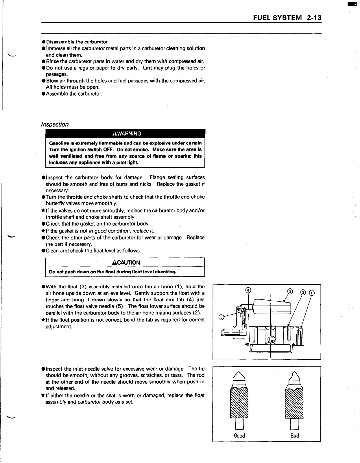
l
With the float (3) assembly installed onto the air hone (I), hold the
air hone upside down at an eye level. Gently support the float with a
finger and bring it down slowly so that the float arm tab (4) just
touches the float valve needle (5). The float lower surface should be
parallel with the carburetor body to the air’hone mating surfaces (2).
*If the float position is not correct, bend the tab as required for correct
adjustment.
@Inspect the inlet needle valve for excessive wear or damage. The tip
should be smooth, without any grooves, scratches, or tears. The rod
at the other end of the needle should move smoothly when push in
and released.
*If either the needle or the seat is worn or damaged, replace the float
assembly and carburetor body as a set.
I
I
Bad
I
Page 31

2-14 FUEL SYSTEM
@Inspect the tapered portion (B) of the screw for wear or damage. @Inspect the tapered portion (B) of the screw for wear or damage.
*If the pilot screw (A) is worn or damaged, on the taper portion, replace *If the pilot screw (A) is worn or damaged, on the taper portion, replace
it. it.
l
Check the spring for weakened condition, replace it, if necessary.
l
Check the spring for weakened condition, replace it, if necessary.
Fuel Shut- Off Solenoid Valve Test
@Unscrew the fuel shut off valve and remove the valve.
@Connect a 12 VDC source to the solenoid as shown.
*If the actuate solenoid plunger (Needle Valve) does not pop in when
the Test Voltage is applied, replace it.
NOTE
Olf
may be necessary to push the plunger slightly for the plunger to
withdraw.
-
-
Page 32

Intake Manifold
Removal:
0 Remove:
Air Cleaner
Carburetor
Control Panel Assembly
@Drain the coolant in the engine (see coolant Draining)
l
Unscrew the manifold mounting bolts in numerical sequence, l/4 turn
at a time, until all bolts are loose.
*If the mounting bolts removal sequence is not followed, manifold
mating surfaces may be warped.
0 Remove the manifold and gaskets.
A. No.1 C.yi. Head
B. No. 2 Cyl. Head D. Intake Manifold
C. Gaskets
FUEL SYSTEM 2-15
Installation Notes
@Before assembling the manifold, install the cylinder heads on each
cylinder and tighten the head bolts in the specified sequence
temporarily (see Cylinder Head Installation Notes).
l
Place a new gaskets on each mating surface, and install the manifold.
l
Follow the sequence shown, tighten the mounting bolts to 4 N-m (35
in-lb).
l
Tighten the bolts in sequence 3 N-m (26 in-lb) at a time until the
torque on each bolt is 6.0 N-m (52 in-lb).
l
Note the position of the different length of bolts.
l
Then tighten the cylinder head bolts to the specified torque.
Head Assembly Installation Note).
Cylinder
Inspection
l
Visually inspect the coolant passage in the manifold for deposits or
corrosion in layers inside the passage, clean the passage if necessary.
@An improperly installed gaskets can cause coolant leakage and air
drawn into the induction passage. Check the gaskets for correct
installation.
NOTE
OSmall coolant leaks appear only as a rust, corrosion or stain.
l
inspect the intake manifold for cracks or porous casting.
l
Cracks not visible to the eye may be detected by coating the suspected
area with mixture of 25 % kelosene and 75 % light engine oil.
l
Wipe the area dry and immediately apply a coating of zinc oxide
dissolved in wood alcohol.
become discolored at the defective area.
*If a cracks is present in the intake manifold, replace it.
l
inspect the gasket surfaces for burrs and nicks.
If a cracks is present, the coating will
Page 33

2-16 FUEL SYSTEM
Fuel Pump
The optional location fuel pump (A) is not installed in the engine
when shipped. The fuel pump must be installed onto an equipment as
inlet
and
outlet pipes are horizontal or vertical (Outlet is up side).
l
The fuel pump cannot be disassembled ,if any damage for the pump
is appeared replace it with a new one.
Fuel Pump Test
Before this test, be sure the battery is fully charged.
explosive. Do not expose to spark or flame. Personal
lniurv could result.
0 Disconnect and plug the fuel pump outlet pipe.
@Connect proper pressure gauge to the fuel pump outlet pipe.
l
Turn the engine switch to the “RUN” position, the fuel pump will
operates. Record the pressure reading. Stop the fuel pump.
ORemove the pressure gauge and connect the outlet fuel tube.
l
Disconnect the fuel pump outlet tube from the carburetor inlet.
l
Put the tube end in a graduated container.
l
Run the fuel pump for 30 seconds. Stop the fuel pump.
container measurement.
l
Compare the readings to the specifications.
*If low, check for clogged or damaged tubes, fuel filter, or fuel tank.
Replace fauln/ fuel pump.
Minimum Specifications
Fuel Pressure
Fuel Flow 160mU30 seconds
19kPa (2.76 psi)
Record the
l_,l “”
I
I
Page 34

Air Cleaner
Element Removal
ORemove the wing bolts, washers and air cleaner case.
l
Take off the air cleaner elements from the body.
A. Wing Bolts D. Elements
B. Washers E. Body
C. Case
Element Installation Notes
l
install the elements correctly on the air cleaner body.
l
The elements can be installed either way on the air cleaner body.
sure the elements is inplace on the air cleaner body.
FUEL SYSTEM 2-17
Be
Element Cleaning and Inspection
NOTE
0 In dusty areas, the elements should be cleaned more frequently than
the recommended intervals.
Clean the element In a well-ventilated area, and take ample care that
there are no sparks or flame anywhere near the worklng area.
Because of the danger of highly flammable Ilqulds, do not use
gasoline or a low flash-point solvent to clean Ihe element.
ORemove the air cleaner element, and separate the foam element (A)
from the paper element (B).
l
Clean the foam element in a bath of detergent and water, and then dry
it with compressed air or by shaking it.
l
After cleaning, saturate the foam element with clean engine oil,
squeeze out the excess, then wrap it in a clean rag and squeeze it as
dry as possible. Be careful not to tear the foam element.
l
Clean the paper element by tapping it gently on a flat surface to remove
dust. If the element is very dirty, replace it with a new one or wash the
element in a detergent and water.
l
Rinse the element until a water is clear. Let the element air-dry
thoroughly before install it.
ACAUTION
Do not use compressed alr to clean the paper element.
paper element.
Do not oil the
Page 35

2-18 FUEL SYSTEM
Cleaner Body and Bracket Removal
*Remove the cleaner body mounting screws, spring washers and plain
washers.
NOTE
0 Do not let the screws, spring washers and plain washers fall into the
carburetor bore.
*Pull the breather hose off the pipe at the back of the body, and remove
the cleaner body.
@Unscrew the carburetor mounting nuts, then take off the bracket.
A. Screws
B. Spring Washers F. Breather Hose
C. Plain Washers G. Pipe
D. Body
E. Bracket
H. U-bend Hose
LMountinag Nuts
Cleaner Body and Bracket Installation Notes
I
When assemljling the cleaner body onto the bracket, do not let *the
screws, spring washers and plain washers fall Into the carburetor
bore.
l
Note the positions of different length of screws and different diameter
of the plain washers.
@Install the U-bend breather hose so that the end of the hose positions
just above the carburetor bore.
l
Connect the breather hose from the
of the cleaner body.
ACAUTION
crankcase
to the pipe at the back
Housing (Case and Body) inspection
l
Clean the housing with detergent and water and dry thoroughly.
@Check the housing for deformation or other damage. The housing
must seal well and permit only filtered air to reach the carburetor.
*If the housing is damaged, it must be replaced.
l
Check that no foreign material is otistructing the air passage.
1
-
Page 36

COOLING SYSTEM 3-1
Cooling System
Table of Contents
Exploded View
Specifications ..............................................................................................................
Cooling System
Coolant..
Coolant Deterioration
Coolant Level Inspection ........................................................................................
Coolant Draining .....................................................................................................
Coolant Filling.. ......................................................................................................
Air Bleeding ........................................................................................................... .3-8
Visual Leak inspection
Cooling System Pressure Testing.. ........................................................................
Flushing
Disassembly and Assembly Precautions
Water Pump
Water Pump Removal
Installation Notes
Disassembly
Pump Parts Inspection .........................................................................................
Assembly Notes ....................................................................................................
Radiator
Removal ................................................................................................................
Radiator Inspection..
Radiator Cap Inspection
Radiator Hose Inspection
Radiator Hose Installation Notes ..........................................................................
Cooling Fan, Fan Belt
Belt Tension Check
Belt Replacement Notes
Removal ................................................................................................................
Installation Notes
Inspection ................................................................ +. .......................................... .3-l 6
Fan Bearing Removal ...........................................................................................
Fan Bearing Installation Notes..
Thermostat..
Thermostat Removal
Thermostat Inspection ......................................................................................... .3-l 8
Therm0 Switch
Therm0 Switch Removal and Installation Notes
therm0 Switch Inspection
............................................................................................................
........................................................................................................... 3-5
...................................................................................................................... 3-6
..............................................................................................
............................................................................................ 3-8
....................................................................................................................
...................................................................
..............................................................................................................
...........................................................................................
..................................................................................................
.......................................................................................................... 3-l 0
.....................................................................................................................
............................................................................................
.......................................................................................
.....................................................................................
...............................................................................................
............................................................................................. ..3-15
..................................................................................... ..3-15
..................................................................................................
..........................................................................
............................................................................................................... 3-18
.............................................................................................
........................................................................................................ ..3-19
.................................................
.................................................................................. ..3-19
3-2
3-4
3-6
3-6
3-6
.3-7
.3-8
3-9
.3-9
3-10
3-10
3-10
3-I I
3-l 1
3-l 2
3-12
.3-l 2
3-13
3-l 4
3-14
3-l 5
3-16
3-16
3-17
.3-l 7
3-18
3-19
3
i
Page 37

3-2 COOLING SYSTEM
ExDloded View
T3
D: Apply engine oil
G: Apply grease
2 Apply a non-permanent locking
agent to the threads
b
Tl: 27 N-m (2.8 kg-m, 20 Mb)
(Therm0 Switch)
T2: 20 N-m (2.0 kg-m, 14.5 &lb)
(Fan Shafl Nut)
T3: 21 N-m (2.1 kg-m, 15.0 A-lb)
(Pump Cover Bolt M8)
-
Page 38

COOLING SYSTEM 3-3
Tl: 2.0 N-m (0.2 kg-m, 17 in-lb) Tl: 2.0 N-m (0.2 kg-m, 17 In-lb)
(Finger Tight) (Finger Tight)
T2: 14 N-m (1.4 kg-m, 10 Mb) T2: 14 N-m (1.4 kg-m, 10 Mb)
(Drain Screws [Black Head]) (Drain Screws [Black Head])
Page 39

3-4 COOLING SYSTEM
Specifications
item Standard
‘Coolant:
Type
Color Green
Mixed ratio 50% solution of ethylene glycol
Freezing point -35°C (-31 “F)
Total amount
Radiator Cap Relief Pressure:
Pressure valve (positive) 73.3 to 102.7 kPa (10.6 to 14.9 psi)
Vacuum Valve (negative) 4.90 kPa (0.71 psi)
Thermostat:
Valve openning temperature 63 to 66°C (145 to 150°F)
Valve full openning lift not less than 7mm (0.28 in) at 80°C (176°F)
Therm0 Switch:
Detect Temperature 108 to 114°C (226 to 237°F)
“A permanent type of antifreeze is not installed in the cooling system when shipped.
Permanent type of antifreeze for aluminum engine and radiator
2.7 L (0.7 us gallon)
Page 40

Cooling System
This engine is equipped with a highly efficient pressurized cooling
system using a thermostat to maintain an optimum operating temperature. Coolant bypasses the closed thermostat when cold until operating
temperature is attained, causing the engine to warm up more quickly. If
the coolant temperature becomes too high, a therm0 switch on the
engine activates the coolant warning lamp to alert the operator or cooling
problem.
1. Water Pump
2. Cylinder Jackets
3. Cylinder Heads
4. Intake Manifold
5. Thermostat
6. Bypass Tube
7. Therm0 Switch
8. Radiator
9. Radiator Cap
10. Cooling Fan
11. Cylinder Block
COOLING SYSTEM 3-5
Page 41

3-6 COOLING SYSTEM
Coolant
Coolant Deterioration
@Visually inspect the coolant in the radiator.
Olf
whitish cotton-like wafts are observed, aluminum parts in the
cooling system are corroded. If the coolant is brown, iron or steel parts
are rusting. In either case, flush the cooling system.
0 If the coolant gives off an abnormal smell when changing, check for a
cooling system leak. It may be caused by exhaust gas leaking in to the
cooling system.
Coolant Level Inspection
@Put the engine on a level surface.
ORemove the radiator cap turning it counterclockwise and check the
coolant level in the radiator.
Always allow the engine to tool before removing the radiator cap.
Then remove the cap slowly and carefully to avoid a possible fast
’ discharge of hot coolant which could cause severe burns.
l
Coolant level must be maintained a level of the filler neck bottom (A).
*If the amount of the coolant is insufficient, fill the radiator up to the
bottom of the radiator filler neck (A) with the coolant, and install the
cap turning it clockwise.
ACAUTION
For refilling, add the specified mixture of coolant and soft water.
Adding water alone dilutes the coolant and degrades its anticorrosion properties. The diluted coolant can attack the aluminum engine
parts. In an emergency, soft water can be added. But the diluted
coolant must be returned to Vie correct mixture ratio within a few
days.
H coolant must be added often, there is probably leakage in the
cooling system. Check the system for leaks (see Visual Leak
Inspection, and pressure Testing).
Coolant Draining
The coolant should be changed periodically to ensure long engine life.
ACAUTION
Use coolant containing corrosion inhibitors made specifically for
aluminum engines and radiators in accordance with the instructions
of the manufactures (see Coolant Filling Section).
Page 42

To avoid burns do not remove the radiator cap or try to change the
coolant when the engine is still hot. Wait until it cools down.
Since coolant is harmful to the human body, do not use for drinking.
ORemove the radiator cap (A) as follows.
0 First turn the cap counterclockwise to the first stop and wait there for
a few seconds.
OPush down the cap, then turn the cap counterclockwise to the next
stop.
0 Lift off the cap.
l Place a suitable container under the radiator. Turn the drain screw (B)
few turns counterclockwise to drain the coolant in the radiator.
COOLING SYSTEM 3-7
ORemove the muffler (see Muffler Removal).
@Remove one of the casecover mounting bolts (A) which attachs the
dipstick tube bracket (B) and casecover to the block together, and
then take off the dipstick assembly.
@To drain the coolant in the engine, place a suitable chute under the
drain screws (black head) (C) located at the lowest water jacket of the
each cylinder to avoid a possible contamination of the starting motor
(D) and igniter.
l
inspect the old coolant for color and smell (see Coolant Deterioration).
Coolant Filling
l
install the drain plugs. Always replace the gaskets with a new ones,
if they are damaged.
@Tighten the drain screws to the specification (see Exploded Views).
@Fill the radiator up to bottom of the radiator filler neck (A) with
coolant, and install the cap turning it clockwise.
NOTE
0 Pour in the coolant slowly so that it can expel the air from the engine
and radiator.
0 To install the radiator cap, push down it and then turn the cap
clockwise to the rest of the way.
Soft or distilled water must be used with the antifreeze in the cooling
If hard water is used in the system, it causes scales accumulation in
the water passages, and considerably reduces the efficiency of tie
II..
NOTE
OChoose a suitable mixture ratio by referring to the coolant
manufacture/s instructions.
Page 43

3-8 COOLING SYSTEM
Original Coolant
Type:
Color:
Mixed ratio:
Freezing Point:
Total amount:
Permanent type antifreeze for aluminum engine
and radiator
Green
50% solution of ethylene giycoi
-35°C (-31°F)
2.7L (0.7 U.S. gallon)
Air Bleeding
Before putting the engine into operation, any air trapped in the
cooling system must be removed as follows.
0 Remove the radiator cap.
@Fill the radiator up to the radiator filler neck with coolant.
l
Check the cooling system for leaks.
l
install the radiator cap.
l
Start the engine, warm it up thoroughly, and then stop it.
l
Check the coolant level in the radiator after the engine cools down.
*If the coolant level is low, add coolant up to the filler neck bottom (A).
Install the cap.
Visual Leak Inspection
Any time the system slowly loses water, inspect for leaks. Small leaks
may appear only a rust, corrosion or stain due to evaporation. Watch for
these trouble spots.
l
Check the water pump housing drainage outlet passage (1) for
coolant leaks.
*If the mechanical seal is damaged, the coolant leaks through the seal
and drain through the passage. Replace the mechanical seal (2).
*If there are no apparent leaks, pressure test the system.
Cooling System Pressure Testing
Air pressure leakage tester can help locate external leaks but they
cannot depended upon to locate small combustion leaks.
ACAUTION
During pressure testing, do not exceed the pressure for which the
system is designed. The maximum pressure is 102.7 kPa (14.9 psi).
ORemove the radiator cap, and install a cooling system pressure tester
(A) on the radiator filler neck.
l
Wet the cap sealing surfaces with water or coolant to prevent pressure
leaks.
@Build up pressure in the system carefully until the pressure reaches 60
kPa (8.7 psi).
l
Watch the pressure gauge for at least 6 seconds. If the pressure holds
steady, the system is all right.
ORemove the pressure tester, replenish the coolant, and install the cap.
*If the pressure drops and no external source is found, check for internal
leaks. Droplets in the engine oil indicate internal leakage. Check the
cylinder head gaskets.
Page 44

Flushing
Over a period of time, the cooling system accumulates rust, scale, and
lime in the water jacket and radiator. When this accumulation is
suspected or observed, flush the cooling system. If this accumulations
is not removed, it will clog up the water passage and considerably reduce
the efficiency of the cooling system.
0 Drain the cooling system.
OFill the cooling system with fresh water mixed with a flushing
compound.
ACZAUTION
Avofd the use of a flushing compound which is harmful to Ule
aluminum englne and radiator. Carefully follow the instructions
supplied by the manufacturer of the cleaning product.
l
Warm up the engine, and run it at normal operating temperature for
about ten minutes.
l
Stop the engine, and drain the cooling system.
0 Fill the system with fresh water.
l
Warm up the engine and drain the system.
0 Repeat the previous two steps once more.
@Fill the system with a permanent type coolant, and bleed the air from
the system.
COOLING SYSTEM 3-9
Disassembly and Assembly Precautions .
l
Prior to disassembly of cooling system parts (radiator, pump, sensor,
etc), wait until the coolant cools down, and then drain the coolant.
@After assembling and filling the system with a coolant, purge any air
from the system.
Page 45

3-10 COOLING SYSTEM
Water Pump
Water Pump Removal
0 Remove:
Muffler (see Muffler Assembly Removal)
0 Loosen the hose clamp (A) and disconnect the radiator hose (B) at
the coolant inlet port of of the water pump (C).
l
Loosen the tube clamp (D), and pull off the coolant by-pass tube (E).
@Unscrew the water pump mounting bolts, and remove the water pump
assembly.
NOTE
0
Note the position of different length of bolts so they can be installed
in their original positions.
Installation Notes
@Chip the old gasket off the mating surfaces of the casecover and pump
housing.
l
Put a new gasket on the pump housing.
l
Be sure to suitable set the pump gear to be meshed with the cam gear
when installing the pump assembly.
position.
@Install the mounting bolts and tighten them to the specification (see
Torque Table).
0 Note the p.osition of different length of bolts.
Do not force the pump into
Boll Dimensions
A. Bolt M6 I = 75 mm (2.95 in)
B. Bolt M6 I = 65 mm (2.56 in)
C. Bolt M6 I = 70 mm (2.76 In)
D. Bolt M6 I = 45 mm (1.77 in)
Disassembly
For disassembly, follow the steps (A - J) below (see Illustration).
NOTE
0
Do not
unless they are to be replaced.
A. Plastic pump gear (1)
B. Dowel pin (2)
C. Claw washer (3)
D. Extract the impeller subassembly (12)(11)(10)(9)(8)(7) from the
E. Mechanical seal cartridge (6)
F. Oil seal (4)
G. Dowel pin (11)
H. Impeller (12)
I. Mating ring (7) and cup-gasket (8)
J. O-ring (10)
1. Pump Gear
2. Dowel Pin (1)
3. Claw Washer
4. Oil Seal
5. Drainage outlet passage 12. Impeller
6. Cartridge
7. Mating Ring
attempt
pump housing (13).
to remove the mechanical seal, oil seal and O-ring
8. Cup Gasket
9. Pump Shaft
10. O-Ring
11. Dowel Pin (2)
13. Pump Housing
I
Page 46

Internal Parts - Mechanlcal Seal
1. Mating Ring (Floating Seat)
2. Cup Gasket (Chusion Ring)
3.
Seal Ring
4. Bellows
5. Spring Retainer
6. Coil Spring
7.
Casing
8. Cartridge
Pump Parts Inspection
@Clean All parts except plastic and rubber parts in a bath of high
flash-point solvent and dry them compressed air. Clean non-metal
parts with detergent and water, and dry them.
l
inspect the pump housing for damage. Mating surfaces should be
smooth and free of burrs and nicks. Replace the gasket if necessary.
l
Check the other parts for wear or damage, replace the parts if
necessary.
*If the mechanical seal is damaged, the coolant leaks through the seal,
and drain through the drainage outlet passage.
*If the oil seal is damaged, the engine oil drain through the drainage
passage.
*If the mechanical seal parts are damaged, replace the seal as a set.
l
Visually check the impeller.
*lf the surface is corroded, or if the blades are damaged, replace all
internal pump parts.
COOLING SYSTEM 3-11
-
@Measure the outside diameter (B) of the impeller shaft (A) end with a
micrometer at several points.
*If the shaft end diameter is less than service limit, replace the shaft.
Outside Diameter of Impeller Shaft End
Service Limit: 9.935 mm (0.3911 in)
” ”
‘s‘.*i,;
.*1
‘,’ .I
..I ._
‘;; ,
- ,
.,:. ,
,.::““,z
,,,
I *\ ;,:,t
>.
Assembly Notes
l
When installing the mating ring (1) into the cup gasket (Z), moisten
outside surface of the mating ring with fresh water and then push the
ring into the stop end. Do not damage mating surfaces.
OPack some amount of high temperature grease into the oil seal (3).
Press in the oil seal using a suitable tools so that the oil seal is flush
with the shoulder surface.
-
0 The oil seal must be assembled with spring loaded lip toward inside
of the engine.
NOTE
Page 47

3-12 COOLING SYSTEM
OWhen installing the impeller (4) sub assembly to the housing(5). coat
mating surfaces between the mating ring and seal ring (6) with a clean
water.
@To avoid oil seal damage, coat thin film of engine oil on the pump shaft
(7). and then carefully insert pump shaft into the housing.
Radiatdr
Removal
Always allow the engine to cool before removing the radiator cap.
Then remove the cap slowly and carefully to avoid a possible fast
discharge of hot coolant which could cause severe burns.
ORemove the radiator cap and drain the coolant in the radiator (A) (see
Coolant Draining).
l
Loosen the hose clamps (B), and disconnect the radiator hoses (C)
at the coolant inlet and outlet of the radiator.
l
Unscrew the radiator mounting bolts (D), and remove the distance
collares (E).
l
Carefully remove the radiator with cooling air duct (F) to ivoid
damaging the fan blades.
.’
Radiator Inspection
l
Check the radiator core.
*If the corrugated fins are deformed, carefully straighten them with the
blade of thin screw driver (A).
l
inspect the inlet and outlet tubes for cracks, kinks, dents, and fractured
seams. Repair or replace the radiator, if necessary.
l
Check for dirt and insects that may be lodged in the radiator.
them out by using compressed air or a low-pressure washer.
I
Using high-pressure water, as from a car wash facility, could damage
the radiator fins and impair the radiator’s effectiveness.
ACAUTION
Clean
Page 48

l
lf the air passages of the radiator core are blocked more than 30% by
unremoval obstructions or irreparably deformed fins, replace the
radiator with a new one.
*If a radiator leak is detected, but cannot be spotted visually, test it as
follows:
1. Install the radiator cap, and plug the overflow tube (3) and inlet pipe
(1). Attach an air hose (4) to the outlet connection (2).
2. Pressurize the inside of the radiator with compressed air to about 50
to 70 kpa (7 to 10 psi).
3. Submerge the radiator in water and look for bubbles (5) which
indicate the location of the leak.
4. Repair any leaks or replace it with a new one.
CO.OLlNG SYSTEM 3-13
l
Check the radiator filler neck for signs of damage.
l
Check the condition of the top (A) and bottom (B) sealing seats in the
filler neck. They must be smooth and clean for the radiator cap to
function properly.
Radiator Cap inspection
The radiator cap has two functions:
1. Allow atmospheric pressure to enter the cooling system.
2. Prevents coolant escape at normal operating pressure.
A pressure valve (D) in the cap permits the escape of coolant or steam
when the pressure in the system rises above the relief pressure.
A vacuum valve (E) in the cap opens when needed to prevent a
vacuum in the cooling system.
l
Check the condition of the valve spring (A), and the top (B) and
bottom (C) valve seats of the radiator cap.
*If any one of them shows visible damage, replace the cap.
l
Wet the radiator cap (B) sealing surfaces with water or coolant to
prevent pressure leaks.
l
install the cap on a cooling system pressure tester (A).
awatching the pressure gauge, pump the pressure tester to build up the
pressure. The cap must retain the pressure at least 6 seconds. Also the
cap must open at the pressure shown in the table.
Radiator Cap Relief Pressure
Pressure Valve: 73.3 to 102.7 kPa (10.6 to 14.9 psi)
Vacuum Valve: 4.90 kPa (0.71 psi) (vacuum)
*If the cap cannot hold the specified pressure, or if it holds too much
pressure, replace it with a new one.
Page 49

3-14 COOLING SYSTEM
Radiator Hose Inspection
l
ln accordance with the Periodic Maintenance Chart, visually inspect
the hoses (A) for signs of deterioration. Squeeze the hose. A hose
should not be hard and brittle, nor should it be soft or swollen.
0 Replace any damaged hose.
NOTE
0 Hoses can deteriorated on the inside and still appear to be in good
condition on the outside.
Radiator Hose installation Notes
l
install the radiator hoses being careful to follow bending direction (see
Exploded View). Avoid sharp bending, kinking, flatting, or twisting.
NOTE
OLocate the hose clamps (A) properly over fhe connections. A
pressurized cooling system will blow a hose that is not installed
properly. Tighten the hose clamps securely.
Page 50

I---
_-.
-_‘-
/L
Cooling Fan, Fan Belt
The only service on the cooling fan is to be sure the fan blades are not
deformed, and the blade tips are far enough from the air duct to not strike
the duct.
The fan belt should be neither too tight nor too loose.
Belt Tension Check
0 Remove:
Radiator (see Radiator Removal)
l
Measure the belt tension using a proper belt tension gauges (1).
Follow the manufacturer’s instructions for use of the belt tension
gauge. The belt tension is adjusted between 25 kg (55 lb) and 40 kg
(88 lb) in the factory for the manufacturing standard.
*If the belt tension is less than specified limit, adjust or replace the belt
(2).
Bell Tenslon Service Limit
.18 kg (40 lb)
COOLING SYSTEM 3-15
*If the belt tension gauge is not available, push (3) the belt with a
thumb strongly at the middle between sheaves (l)(2). The slack (4)
of the belt correspond the measurements of the belt tension gauge are
as follow. Use the table as a guide line.
Belt Tension Measurements Slacks
25 kg (55 lb) -
40 kg (88 lb) - 9 mm (0.35 In)
18 kg (40
lb) -
12 mm (0.47 In)
17 mm (0.87 In)
Belt Replacement Notes
l
When replacing the fan belt, use only factory recommended belt with
the proper length. To compensate for the belt length allowance, select
appropriately sized shim(s) (A) from the table to obtain proper level
of the belt tension (25 - 40 kg).
Fan Belt
92180-2013’
NO
of shim 92180-2014’
l
Part Number
t = Thickness of shim
t = 0.6 mm
t = 1.2mm
A Belt: Smaller allowance
D Belt: Bigger allowance
A B C D
1 2 1 2
1 1
NOTE
0
When tightening the sheave/hub (B) mounting nuts (C). rotate the
fan in either direction to avoid pinching the belt (0).
Drive Belt Specification
MITSUBOSHI - 59011-2058
Page 51

3-16 COOLING SYSTEM
Removal
0 Remove:
Radiator (see Radiator Removal)
0 Remove the radiator brackets (E).
0 Disconnect the wire tie (D) which binding the pressure switch, pulser
coil and primary ignition coil leads to the radiator bracket (E).
0 Disconnect the therm0 switch (A) lead and coolant bypass tube(B).
ORemove the therm0 switch.
0 Unscrew the bracket mounting bolts (C) and nuts (F), then remove
the radiator mounting brackets.
OHold the fan drive sheave/hub (A) with a suitable spanner (D) to
prevent rotating the sheave/hub.
@Unscrew the sheave/hub mounting nuts (B), and take off the
sheave/hub and shims (C).
0 Remove the fan belt rolling over the fan sheave.
NOTE
0 When removing the fan belt, note the belt so that it may be
reinstalled on the sheaves to rotate same direction as original installation.
l
Unscrew the mounting bolts (A), and take off the cooling fan (C) and
fan sheave (B).
Installation Notes
l
Install the cooling fan as “AISHIN” raised lettering (,
facing toward the radiator.
l
Clean the drive belt by wipping with a clean cloth
off any spilled oil or grease. Do not use solvent.
l
Install the belt on the sheave to rotate same direction as original
installation.
l
When tightening the sheave/hub mounting nuts, rotate the fan in
either direction to avoid pinching the belt.
l
Check the belt tension.
A) on the fan boss
immediately wipe
Inspection
l
Be sure the fan blades are straight. Deformed blades reduce the
cooiing system efficiency and throw the fan out of balance.
l
Check for excessive side wall wear of the sheaves and belt, replace if
necessary. The belt and sides of the sheaves should wear evenly.
*Check to be sure dirt has not lodged and packed in the sheave
V-grooves.
l
Check the belt for swells or lumps, replace if necessary.
Page 52

Fan Bearing Removal
0 Remove:
Fan Mounting Bracket (4)
l
Unscrew the fan shaft nut (1). and remove the shaft (3) and washer
(2).
l
To check the ball bearing (5), rotate the bearing slowly by finger; if any
roughness is noted, the bearing should be replaced.
Do not allow a flame or heating element to come in direct contact with
the oil. Heat the oil in a well-ventilated area. Plan a safe handling
procedure to avoid burns.
l
To remove the ball bearing, heat the bearing housing in a hot 150°C
(302°F) oil.
0 Use a heat shield gloves to prevent burns.
l
Place the bearing housing on a bench with bearing side up and take
off the bearing with a suitable tools.
COOLING SYSTEM 3-17
I
Do not remove the bearing unless it is necessary. Once it has been
removed, it must be replaced.
ACAUTION
Fan Bearing fnsta llation Notes
l
Coat the bearing surfaces with a light film of engine oil.
l
Use a bearing driver, press in the fan side bearing flush with the
housing (1).
l
install opposite side of bearing using a bearing driver until it stops at
the stop [spacer(2)] in hole.
l
install the fan shaft (6), washer (5) and nut (4), then tighten the nut
to the specified torque (see Exploded View).
1. Housing 4. Nut
2. Spacer
3. Circlip 6. Fan Shaft
5. Washer
I
I
Page 53

3-18 COOLING SYSTEM
Thermostat
This cooling system is equipped with a thermostat to maintain a
optimum operating temperature.
stat when cold until operating temperature is attained,
Coolant bypasses the closed thermo-
Thermostat Removal
0 Remove
Radiator (see Radiator Removal)
Cooling Fan (see Cooling Fan Removal) -
@Loosen the hose clamp (A) and disconnect the radiator hose (B) at
the thermostat cover.
l
Unscrew the thermostat cover bolts (C), and remove the cover.
l
Take off the thermostat (D).
NOTE
0 With the thermostat installed, the jiggle valve may be positioned
up-side of the thermostat when installing.
Thermostat Inspection
@Remove the thermostat, and check the jiggle valve (A) for sticking or
binding on the flange (8) due to accumulation of a rust, scale or lime.
Clean up the valve to ensure free movement of the valve (C), if
necessary.
l
inspect the thermostat valve (1) at room temperature.
*If the valve is open, replace the valve with a new one.
@To check valve openning temperature, suspend the thermostat and an
accurate thermometer (2) in a container filled with a water.
@Place the container over a source of heat and gradually raise the
temperature of the water while stirring the water gently.
0
Watch the valve. The valve should begin to open at the temperature
specified.
0
It should be fully opened to 7mm (0.28 in) or more at the temperature
specified.
Thermostat Valve Specification
Begin Opening 63 to 66 “C (145 to 150°F)
Full Open 60°C (176°F)
The thermostat and thermometer must not touch the container sides.
*If the thermostat fails any of these check, replace it.
-
Page 54

Therm0 Switch
When coolant temperature rises above 111 “C (232’F), the therm0
switch detects this and turns on a warning light on dash. Whenever you
start the engine, make sure the warning light is not on in started engine.
If the warning light comes on, stop the engine immediately, and check
the cooling system for over heating. Over heating can caused by:
Lack of coolant
Loose or slipping fan belt
Clogging of cooling system
Malfunction water pump or thermostat
Check the coolant level and temperature frequently.
Therm0 Swtich Removal and Installation Notes
*Drain the coolant (see Coolant Draining).
l
Disconnect switch lead terminal (A).
0 Loosen the bypass tube clamp (C) and disconnect the tube (B).
l
Unscrew the therm0 switch and remove it.
l
When installing the therm0 switch (D), apply a non-permanent
locking agent to the threads and tighten the switch to the specified
torque (see Exploded View).
COOLING SYSTEM 3-19
therm0 Switch Inspection
l
Using a ohmmeter, check to see that only the connections in the table
have continuity.
*lf the switch has an open or short, repair it or replaced it \?rith a new
one.
Therm0 Switch Connectlons
0 Rising temperature:
From Off to On at 108 - 114°C (226 - 237’F)
l
Falling temperature:
From On to FF at 101 - 107°C (214 - 226’F)
ON: Continuity
OFF: lnflnit
l
Suspend the switch (2) in a container of coolant (3) so that the
temperature sensing projection and threaded portion are submerged.
O-Suspend an accurate thermometer (1) in the coolant.
NOTE
0 The switch and thermometer must not touch the container sides or
bottom.
l
Place the container over a source of heat (4) and gradually raise the
temperature of the coolant while stirring the coolant gently.
Page 55

Engine Top End
ENGINE TOP END 4-l
Table of Contents
Exploded View
Specifications
Special Tools
Cylinder Head..
Compression
Cylinder
Installation Notes
Push Rod Installation Notes
Push Rod Inspection
Disassembly and Assembly
Cleaning
Va Ives ........................................................
Clearance Inspection
Clearance Adjustment..
Valve Seat Inspection..
Valve Seat Repair ..................................................................................................
Valve Head Thickness
Valve Stem Run Out
Valve Stem Diameter ........... .
Valve Guide Inside Diameter..
Valve Spring Inspection..
Cylinder, Piston .........................................................................................................
Piston Removal..
Piston Installation Notes
Piston/Cylinder Seizure.. ......................................................................................
Piston Cleaning
Piston Ring and Ring Groove Wear..
Piston Ring End Gap..
Piston Pin, Piston Pin Hole, and Connecting Rod Wear
Piston Diameter
Cylinder
Cylinder Boring and Honing
Muffler
....................................................................................................................... 4-23
Muffler Assembly Removal
Muffler Assembly Installation Notes
Inspection
............................................................................................................ 4-2
..............................................................................................................
..............................................................................................................
............................................................................................................
Measurement..
Assembly
Head
...................................................................................................
.............................................................................................
Inspection..
and
............................................................................................ 4-l 1
.............................................................................................
...................................................................................................
.....................................................................................................
.................................................................................................... 4-20
Inside Diameter
............................................................................................................. 4-23
.................................................................................. 4-6
Removal ........................................................................
................................................................................... 4-8
....................................................................................
....................................................................................... 4-9
....................................................
.
......................................................................................... 4-l 1
.........................................................................................
........................................................................................... 4-l 5
................................................................................ 4-l 5
.............................................................................
...................................................................................... 4-l 5
.....................................................................................
..................................................................
.........................................................................................
....................................
...................................................................................... 4-20
................................................................................
.................................................................................. 4-23
................................................................... .4-23
.......... ..4- 11
4-4
.4-5
4-6
.4-6
.4-7
.4-8
4-8
4-12
4-l 2
4-l 5
.4-l 5
4-l 6
4-16
..4-17
4-l 8
4-18
.4-l 8
.4-l 9
4-20
4-21
I
4
Page 56

4-2 ENGINE TOP END
Exoloded View
Tl: 8.8 N-m (0.9 kg-m, 78 in-lb)
12: 21.0 N-m (2.1 kg-m, 15 A-lb)
0: Apply engine oil
G: Apply Grease
Page 57

ENGINE TOP END 4-3
ll: 21 N-m (2.1 kg-m, 15 tt-lb)
L: Apply a non-permanent kxktng agent
to the threads.
Page 58

4-4 ENGINE TOP END
Soecifications
Item Service Limit
Cylinder Head:
Cylinder compression (M IN)
Cylinder head warp 0.06 mm (0.002 in.)
Valves:
Valve seating surface width
Valve head thickness Intake, Exhaust 0.6 mmm (0.024 in)
Valve stem run out Intake, Exhaust
Valve stem diameter Intake 5.945 mm (0.2341 in)
Valve guide inside diameter Intake 6.045 mm (0.2379 in)
Valve spring free length Intake, Exhaust 29.70 mm (1 .I 7 in)
Rocker arm push rod runout Intake, Exhaust 0.80 mm (0.03 in)
Rocker shaft outside diameter Intake, Exhaust 11.949 mm (0.4704 in)
Rocker arm bearing inside diameter Intake, Exhaust 12.074 mm (0.4754 in)
Cylinder, Piston:
Piston ring/groove clearance
Piston ring thickness
Piston ring end gap Top, Second
Piston pin outside diameter
Piston pin hole inside diameter
Connecting rod small end inside diameter 17.051 mm (0.6713 in)
Cylinder inside diameter: Standard Cylinder 76.067 mm (2.9948 in)
Cylinder bore out of round
Intake, Exhaust
Exhaust 5.925 mm (0.2332 in)
Exhaust 6.055 mm (0.2384 in)
Top
Second
Top, Second
Oil 1.5 mm (0.06 in)
0.25 mm Oversize 76.317 mm (3.0046 in)
0.50 mm Oversize 76.567 mm (3.0144 in)
0.75 mm Oversize
[1171 kpa (170 psi)] (MIN)
2.0 mm (0.08 in)
0.05mm (0.002 in)
0.15 mm (0.006 in)
0.12 mm (0.005 in)
1 .12 mm (0.044 in)
1.2 mm (0.05 in)
16.975 mm (0.6683 in)
17.041 mm (0.6709 in)
76.817 mm (3.0242 in)
0.056 mm (0.0022 in)
item Standard
Valve Clearance Intake, Exhaust
Valve Seating Surface Angle Intake, Exhaust 45
Valve Seating Surface Width Intake, Exhaust 0.5 to 1 .l mm
Valve Guide Inside Diameter Intake, Exhaust 6.00 to 6.012 mm
Cylinder Bore Diameter
Standard cylinder 76.000 to 75.980 mm
0.25 mm Over size 76.250 to 76.230 mm
0.50 mm Over size 76.500 to 76.480 mm
0.75 mm Over size 76.750 to 76.730 mm
0.25 mm (0.01 in)
(0.02 to 0.043 in)
(0.2362 to 0.2367 in)
(2.9921 to 2.9913 in)
(3.0020 to 3.0012 in)
(3.0118 to 3.0110 in)
(3.0216 to 3.0209 in)
Page 59

Special Tools
Compression Gauge Assembly, Ml 4 x 1.25: 57001-I 23
ENGINE TOP END 4-5
Valve Seat Cutter Holder, @6: 57001-I 360
Piston Ring Pliers: 57001-I 15
Piston Ring Compressor Grip: 57001-I 095
Piston ding Compressor Belt, Q67 - @79: 57001-I 097
Valve Seat Cutter, 45” - @35: 57001-I 116
Valve Seat Cutter, 30” - @33: 57001-I 199
Valve Seat Cutter, 45” - @30: 57001-I 187
Valve Seat Cutter Holder Bar: 57001 -1128
Valve Seat Cutter, 30” - @30: 57001-I 120
Page 60

4-6 ENGINE TOP END
Cylinder Head
Compression Measurement
l Before measuring compression, do the following.
0 Be sure the battery is fully charged.
OThoroughly warm up the engine so that engine oil between the piston
and cylinder wall will help seal compression as it does during normal
running.
OStop the engine.
@Disconnect the spark plug caps of each cylinder and remove the spark
plugs.
@Attach the compression gauge assembly (A) (Special Tool:
57001-I 23) firmly into the one plug hole.
@Ground the spark plugs to the engine.
To avoid fire, do not ground the spark plugs in closed positions to the
plug holes. Keep the plugs as far away as possible from the plug
holes.
@Using the starter motor, turn the engine over with the throttle fully
open until the compression gauge stops rising; the compression
reading obtainable.
ORepeat the measurement to the other cylinder.
Cylinder Compression (MN)
1171 kPa (170 psi)
*If the compression is higher than the specified value, the piston rings,
cylinder and valves are probably in good condition.
*If the compression is too high, check the following.
(1) Carbon build-up on the piston head and cylinder head - clean off
any carbon on the piston head and cylinder head.
(2) Cylinder head gasket - use only the proper gasket. The use of a
gasket of incorrect thickness will change the compression.
(3) Valve guides and piston rings - rapid carbon accumulation in the
combustion chamber may be caused worn valve guides and/or
worn piston oil rings. This may be indicated by white exhaust
smoke.
* If cylinder compression is lower than the (MIN), check the following:
(1) Gas leakage around the cylinder head - replace the damaged
gasket and check the cylinder head warp.
(2) Condition of the valve seating.
(3) Valve clearance.
(4) Piston/cylinder wear, piston seizure.
(5) Piston ring, piston ring groove.
Cylinder Head Assembly Removal
0 Remove:
Radiator and it’s Bracket
Air Cleaner and Carburetor
Muffler
Intake Manifold
Thermostat (No. 2 Cylinder)
Spark Plug
l Unscrew the rocker cover mounting bolts, and remove
gasket (o-ring). Do not lose the distance collars in the
A. Rocker Cover (No. 1 Cylinder)
B. Rocker Cover (No. 2 Cylinder)
C. Mounting Bolts
D. Collars
! the cover
bolt holes.
and
J
Page 61

l
Loosen the cylinder head bolts l/4 turn in the sequence shown.
ENGINE TOP END 4-7
I-,
ACAlJllON
If the above procedure Is not followed, the cylinder head may be
warped during removal.
ORepeat the sequence until all bolts are removed and lift off the cylinder
head assembly.
NOTE
0 Mark the push-rods so they can be installed in their original position
during assembly.
0 Note the position of the special bolt (A) for reinstalling the cylinder
head.
(No.2 Cyl. shown)
Installation Notes
l
Clean the mating surfaces of the cylinder heads and cylinder.
l
install the push rods in their original positions on each cylinder. (see
Push Rod Installation)
@Put a new gaskets and the cylinder head assemblies on each cylinder,
then let the cylinder heads with push rods aligned under the rocker
arms.
NOTE
OAs the head gaskets are coated with sealing agents, be carefull not
to injure the surfaces of them.
l
install the head bolts noting the position of special bolts (A) and
tighten them temporarily.
(No.1 Cyl. shown)
l
install the intake minifold onto cylinder heads. (see Intake Manifold
Installation Note)
l
Then tighten the head bolts to the specification (see Exploded View).
0
Follow the sequence shown, tighten the head bolts to 13 N-m (115
lb-in).
OTighten the bolts in sequence 3.0 N-m (27 lb-in) at a time until torque
on each bolt is 21 N-m (186 lb-in).
I
ACAUTION
A torque wrench must be used to prevent loose or overtight the head
bolts which may result in warping of the cylinder head.
Page 62

.
4-8
ENGINE TOP END
Push Rod Installation Notes
@Align (RI ) mark on the flywheel (1) with (A) mark on the breather
chamber cover (2) turning the flywheel clockwise.
l
install the push rods in their original positions on each cylinder.
OTo install the push rod in a correct position on the tappet, insert the
push rod so end of the push rod is sliding down along inside wall of
the crankcase and position the push rod end on to the tappet.
l
Check both intake and exhaust push rods on each cylinder are lowest
position on the cam lobes, if not turn the flywheel clockwise one turn
(360”) and align both marks on the flywheel and breather chamber
cover again.
0 Be sure the end of the push rods are correctly seated on the tappets.
1. Push Rods 4. Inside Walls
2. Tappets 5. Sliding Down
3. Lowest Cam Lobes
Push Rod Inspection
l
Place the rocker arm push rod in V blocks that are as far apart as
possible, and set a dial gauge on the rod at a point halfway ween
between the blocks. Turn the rod to measure the runout. The difference between highest and the lowest dial readings is the amount of
runout.
*If the runout exceeds the service limit, replace the rod.
Rocker Arm Push Rod Runout
Service Limit:
0.8 mm (0.03 in)
Disassembly and Assembly
(Valve Mechanism Removal and Installation)
NOTE
0 When removing the valve mechanism parts, note the position of
them so that they may be reinstalled in their original position during
assembly.
ORemove one of the rockershaft circlip (A) with a circlip pliers.
0 Remove the rocker armes (B) by pushing the rocker shaft (C) out the
side from which the circlip was removed.
Page 63

l
Support the valve head in the combustion chamber with a suitable
block.
l
To remove the spring retainer (A), push down the retainer with thumbs
and shift (C) the retainer to a side hole (6) on the retainer.
0 Remove the spring and valve.
@Remove the stem seals (A) and bottom spring retainers (C).
NOTE
0 It is not necessary to remove the stem seal unless it is being replaced.
0 Bottom spring retainer can only be removed with stem seal.
0 Valve guide (B) is not replaceable, do no rernove it.
.
ENGINE TOP END 4-9
l
Valve Installation
OApply engine oil to the valve stem to avoid damaging the stem seal.
OCheck to see that the valve moves smoothly up and down in the guide.
OCheck to see that the valve seats properly in the valve seat. If it does
c
not, repair the valve seat.
0 Rocker Arm Installation
OApply engine oil to the bearing surface of rocker arm.
OPut engine oil to the rocker arm where it touches the push rod and
valve stem end.
0 Install the rocker arm.
Cleaning and Inspection
@Scrape the carbon deposits from the head and exhaust port with a
suitable tool.
OTo avoid gouging, use scrapers that are made of a material that will
not cause damage.
@Clean the head in a bath of high flash-point solvent and dry it with
compressed air.
area, and take care that
there are no sparks or flame anywhere near the working area; this,
includes any appliance with a pilot light. Do not use gasoline or a low
flash-polnt solvent to clean the cylinder head. A fire or explosion
l
Lay a straightedge (A) across the gasket surface of the head at several
different points, and measure warp by inserting a thickness gauge (6)
between the straightedge and head.
+ If warp exceeds the service limit, repair the gasket surface. Replace the
cylinder head if the mating surface is badly damaged.
Cylinder Head Warp
Service Limit: 0.06 mm (0.002 in)
Page 64

I - --
_..~----
-
4-10 ENGINE TOP END
l
Check the cylinder head for cracks or other damage.
l
Cracks not visible to the eye may be detected by coating the suspected
area with mixture of 25% kelosene and 75% light engine oil.
@Wipe the area dry and immediately apply a coating of zinc oxide
dissolved in wood alcohol. If a cracks is present, the coating will
become discolored at the defective area.
*If a cracks is present in the cylinder head, replace it.
l
inspect the gasket surface for burrs and nicks.
0 Inspect the cylinder head for accumulation of rust, scale and lime in the
water jacket (A).
*If this accumulation is observed, flush the cooling system (see
Flushing in Cooling System chapter).
*+*v~*>~ ,, “““I”i;“~
#Y “
4
@CA
I
OClean and measure the diameter of the rocker shaft (A) with a
micrometer at several points.
*If the outside diameter is less than the service limit, replace the shaft.
Rocker ShaH Outside Diameter
Servke Limit: 11.949 mm (0.4704 in)
l
Clean and inspect the rocker arm where it touches the push rod and
valve stem.
*If the contact points (A) are worn or damaged, replace the rocker arm.
0 Measure the inside diameter of the rocker arm bearing (B) at several
points using a dial bore gauge or inside micrometer.
*If the inside diameter is more than the service limit, replace the rocker
arm.
Rocker Arm Bearing lnslde Diameter
Service Limit: 12.074 mm (0.4754 in)
.
Page 65

Valves
Clearance Inspection
NOTE
0 Valve clearance must be checked when the engine is cold (at room
temperature).
ORemove the rocker chamber cover (see Cylinder Head Removal).
l
Place the piston at top dead center (TDC) of the compression stroke
turning the crankshaft clockwise facing the flywheel.
No. 1 Cylinder:
OAlign (!,) mark on the flywheel (1) with (A) mark on the breather
chamber cover (2) as shown.
0 Check the intake and exhaust valves are closed completely, if not turn
the flywheel one turn (360”) clockwise and align both marks on the
flywheel and cover again.
No. 2 Cylinder:
OAlign ($ ) mark on the flywheel with (A) mark on the breather
chamber cover. Follow No. 1 Cylinder alignment procedure described
above.
aThen check the clearance.
0 Using a thickness gauge (A), measure the valve clearance between the
rocker arm and the valve stem end.
*If the valve clearance is incorrect, adjust it.
Valve Clearance (when cold)
Intake, Exhaust: 0.25 mm (0.01 in)
.
ENGINE TOP END 4-11
Clearance AQustrnent
l
Since the valve repairs change the valve clearance, adjust the valve
clearance to the specification.
l
Assemble the cylinder head and install the cylinder head assembly on
the block (see cylinder Head Installation Notes).
l
Turn the crankshaft proper direction until the piston is at TDC of the
compression stroke (described above).
l
Loosen the locknut (C) and valve clearance adjusting screws( 6).
l
insert a 0.25 mm (0.01 in) thickness gauge (A) between the adjusting
screw and valve stem, and tighten the adjusting screw until the
thickness gauge begin to bind between the rocker arm and valve stem
end. Use a sweeping motion with the thickness gauge while making
this adjustment.
l
Holding the adjusting screw with a spanner, tighten the locknut to the
specified torque (see Exploded View).
0 Do not overtighten.
:
Page 66

4-12 ENGINE TOP END
NOTE
OFor designing an adjustment tools, refer to the following
dimensional specifications.
1: 8.80 to 9.00 mm (0.346 to 0.354 in)
2: 3.85 to 4.25 mm (0.15 to 0.17 in)
3: 2.80 to 3.00 mm (0.11 to 0.12 in)
4: 2.00 to 2.50 mm (0.08 to 0.10 in)
5: M5 PO.5 screw
6: Rocker Arm
Valve Seat Inspection
0 Remove the valve.
0 Inspect the valve seats for damage.
*If the seats are warped or distorted by beyond reconditioning, replace
the cylinder head.
l
Pitted or worn the valve seats can be refaced. Lap the valves to the
seats after refacing.
@Coat the valve seat with machinist’s dye.
l
Push the valve into the guide.
*Rotate the valve against the seat with a lapping tool.
0 Pull the valve out, and check the seating pattern on the valve head.
must be the correct width and even all the way around.
NOTE
0
The valve stem and guide must be in good condition or this check
will not be valid.
*If the valve seating pattern is not correct, repair the seat.
Valve Seating Surface Width (STD)
Inlet, Exhaust:
0.5 - 1.1 mm (0.02 - 0.043 in)
It
00
Good Too Wide
Valve Seat Repair
l
Follow the manufacture’s instructions for use of valve seat cutters
(special tools).
Use vlese Cutters
Intake Valve
Seat Cutter
Outslde Cutter
Exhaust Valve
Seat Cutter
Outslde Cutter
Use this Holder and Bar
Holder - 06.0
Bar 57001-1126
*If the manufacture’s instructions are not available, use the following
procedure.
Seat Cutter Operating Cares:
1. This valve seat cutter is designed only for valve seat repair.
Therefore the cutter must not be used for other purposes.
45’ * Q35.0
30’ - a33.0
45” - Q30.0 57001-l 167
30” - Q30.0
57001-l 360
57001-1116
57001-1199
57001-l 120
00
Too Narrow
Uneven
Page 67

Do not drop or hit the valve seat cutter, or the diamond particles
2.
may fall off.
3. Do not fail to apply engine oil to the valve seat cutter before
grinding the seat surface. Also wash off ground particles sticking
to the cutter with washing oil.
NOTE I
0 Do not use a wire brush to remove the metalparticles from the cutter.
It will take off the diamond particles.
4. Setting the valve seat cutter holder. in position, operate the cutter
with one hand. Do not apply too much force to the diamond
portion.
NOTE
0 Prior to grinding, apply oil to the cutter, and during the operation
wash off any ground particles sticking to the cutter with washing
oil.
ENGINE TOP END 4-13
1. Cutter
2. Cutter Holder
3. Bar
After use wash the cutter with washing oil and apply a’thin layer of
5.
engine oil before storing.
Marks Stamped on the Cutter:
The marks stamped on the back of the cutter represent the following.
1 . . . . . . . . . . . . . . . . . . . . . . . . . . . . . . . . . . . . . . . . . . . . . . . . Cutter number, selected from 1 to 12
30” . . . . . . . . . . . . . . . . . . . . . . . . . . . . . . . . . . . . . . . . . . . . . . . . . . . . . . . . . . . . . . . . . . . . . .
. .
37.5 . . .
KS8B .
1. Cutter Outside Diameter
2. Cutter Angle
Operating Procedures:
l
Clean the seat area carefully.
@Recondition the valve seats with the valve seat cutters (45 ‘, 30 “) and
lap the valves.
l
Check the seats for good contact all the way around with machinist’s
dye.
l
Measure the seat width is more than 2.0 mm (0.08 in) the seating
surface should be refaced.
*If the valve seating pattern is not correct, repair the seat.
. . . . . . . . . . . . . . . . . . . . . . . . . . . . . . . . . . . . . . . . . . . . . . . . . . . . . . . . . . . .
. . . . . . . . . . . . . . . . . . . . . . . . . . . . . . . . . . . . . . . . . . . . . . . . . . . . . . . . . . . Manufactured lot number
. . . . . . . . . . . . . . . . Cutter angle
Outer diameter of cutter
Page 68

4-14 ENGINE TOP END
l
Coat the seat with machinist’s dye.
OFit a 45 o cutter (A) to the holder and slide it into the valve guide.
OResurface the valve seat with a 45 a cutter, removing only enough
material to produce a smooth and concentric seat.
ACAlJllON
Do not grind the seat too much. Overgrlndlng will reduce valve
clearance by slnklng the valve Into the head. H the valve sinks too far
Into the head, It will be lmposslble to adlust the clearance and the
cylinder head must be replaced.
Do not turn the cutter counterclockwlse or drop it against the seat,
or it will be dulled.
l
Use a 30 ’ seat cutter (A) to narrow the seat width to the STD width.
OTurn the seat cutter one turn at a time while pressing down very lightly.
Check the seat width after each turn.
ACAUTION
The 30 ’ cutter removes material very qukkly. Check the seat wklth
freauentlv to orevent over arlndlnp.
NOTE
0
Keep the seat width as closely as possible to 0.8 mm (0.03 in).
l
Make a light pass with the 45” cutter to remove any possible burrs at
the edge of the seat.
l
After resurfacing the seat, inspect for even valve seating.
OApply a machinist’s dye to the valve face, insert the valve, and snab it
closed against the seat several times. The valve surface should show
good contact all the way around.
on the valve face. The position of the valve in the seat is evident after
lapping the valve.
*If the seat does not make proper contact, lap the valve into seat with
a vacuum cap tool (A).
l
Coat the face of valve sparingly with a fine lapping compound.
l
Use the vacuum cup tool, to grip top of the valve. Rotate the valve in
a circular motion to lap the valve to the seat.
l
Lift the valve slightly from the seat every 8 to 10 strokes, continue
lapping operation until a uniform ring appears around entire surface
of the valve face.
Be sure the valve seat is centered
@When lapping is completed, wash all parts in solvent to remove
lapping compound. Dry the parts thoroughly.
l
Note the position of the lapping mark on the valve face. The lapping
mark should appear on or near the center of the valve face.
l
When the engine is assembled, be sure to adjust the valve clearances
(see Valve Clearance Adjustment).
Page 69

I
!-k-J
/
!
j
I
I
Valve Head Thickness
0 Remove the valve.
l
Measure the thickness of the valve head.
*if the valve head thickness (valve margin) (1) is less than the service
limit, replace the valve.
Valve Head Thkzkness
Service Limit (IN, EX): 0.6 mm (0.024 In)
Valve Stem Run Out
l
Support the valve in V blocks at each end of the stem.
l
Position a dial gauge perpendicular to the stem.
*Turn the valve and read the variation on the dial gauge.
*If the stem run out is greater than service limit, replace the valve.
Valve Stem Run Out
Service Limit (IN, EX): 0.05mm (0.002 in)
ENGINE TOP END 4-15
I!
Valve Stem Diameter
l
Measure the diameter of the valve stem (A) in two directions at right
angles, at four different positions on the stem.
*If any single measurement is less than the service limit; replace the
valve.
Valve Stem Diameter
Servkx Limit
Intake: 5.945 mm (0.2341 in)
Exhaust: 5.925 mm (0.2332 in)
Valve Guide Inside Diameter
l
Use a small bore gauge or a micrometer to measure the inside diameter
of the valve guide a three places down the length of the guide.
*If the measurement is more than the service limit, replace the cylinder
head with a new one.
Valve Gukte Inside Diameter
Sarvka Limit
Intake: 6.045 mm (0.2379 In)
Exhaust:
6.055 mm (0.2384 in)
Valve Spring Inspection
l
inspect the valve spring for pitting, cracks, rusting, and burrs. Replace
the spring if necessary.
l
Measure the free length of the spring.
*If the measurement is less than the service limit, replace the spring.
Valve Spring Free Len@h
w
Servkx Llmlt 29.70 mm (1.17 in)
Page 70

4-16 ENGINE TOP END
Cylinder, Pistorn
-
Piston Removal
OSplit the crankcase (see Camshatft/Crankshaft chapter).
0 Remove the camshiaft (see Camshaft/Crankshaft chapter).
@Turn the crankshaft to expose the connecting rod cap bolts.
ORemove the bolts and take off the connecting rod caps.
A. Cap Bolts
B. Caps
l
Push the connectilng irod end into the cylinder. end pull the piston and
connecting rod out of the cylinder.
r -
Note a localion ol the, arrow malch mark on the piston head In relation
to MADE IN JAPAN on the connecting rod. No. 1 cyl. piston is
opposlle of No. 2 cyl. piston. Keep parts together as a set.
L
1. Arrow Match Marks 3. Large Chamfers
2. Flywheel Side 4. Raised Letters
-
C. Pry Points
ACAUTlON
(MADE IN JAPAN)
-1
---J
. . .
@Remove one of the piston pin snap rings with needle nose pliers.
A. Piston Pin Snap Rings
B. Pliers
@Remove the piston by pushing the piston pin out the side from which
the snap ring was; removed.
A. Piston Pin
ORemove the top and second rings with a piston ring pliers (special tool:
57001-l 15). If tha special tool is not available, carefully spread the
ring opening with your thumbs and then push up on the opposite side
of the ring to remove it.
ORemove the 3-piece oil
A. Piston Ring Pliers
ring
with your thumbs in the same manner.
Page 71

Piston Installation Notes
*Oil Ring Installation:
OFirst install the expander in the piston oil ring groove so that the
explander ends butt together.
0 Install the upper and lower steel rails. There is no UP or Down to the
rails. They can be installed either way.
A. Expander ends
l install the chrome-plated top ring and second ring with “N” mark
facing up. The rings should turn freely in the grooves.
@Align the piston and rings with the piston ring end gap as shown.
1. Arrow Mlatch Mark
2. Top Ring End Gap, Upper Side Rail End Gap
3. 45”
4. Second Ring End Gap, Lower Side Rail End Gap
ENGINE TOP END 4-17
-
l
Apply engine oil to the piston pins.
*Assemble the pistons onto the connecting rods as follow:
No. 1 Cyl. piston, align the arrow match mark on the piston head with
the raised letters (MADE IN JAPAN) on the connecting rod.
No. 2 Cyl. piston, align the arrow match mark on the piston head with
opposite MADE IN JAPAN on the connecting rod.
A. No. 1 Cyl. Piston
6. No. 2 Cyl. Piston E. Opposite MADE IN JAPAN
C. Arrow Match Marks
l When in.stalling a piston pin snap ring, compress it ortly enough to
install it and no more.
OFit a new piston pin snap1 ring into the scde of the piston so that the
ring opening (A) does not coincide with the notch (B) in the edge of
the piston pin hole.
reuse snap rings, as removal weakens and deforms
ouf and score the cylinder wall.
@Apply engine oil to the piston skirt and the cylinder bore.
0 Using the piston ring comlpressor grip (special tool: 57001-l 095) and
the belt (special tool: 570’01 -1097). insert the piston and connecting
rod into the cylinder.
0 Insert the piston and connecting rod so that the arrow match mark on
the top of the piston facing the flywheel side.
A. Arrow Match Mark
B. Flywheel Side
No. 1. Cylinder Shown
D. MADE IN JAPAN
Q
B
E
Pa
Page 72

4-18 ENGINE TOP END
-
Piston/Cylinder Seizure
l In case of seizure, remove the piston.
l
Visually inspect the cylinder and piston damage.
*If there is only light damage, srnooth the piston with #400 emery cloth.
Remove the small aluminum deposits from the cylinder with #400
emery cloth or light honing.
*If the damage is severe, the both cylinders must be bored oversize and
an oversized pistons installed.
Piston Cleaning
ORemove the piston (and pistonrings (see Piston and Ring Removal).
-Never clean lhe piston head with the engine assembled.
partkles will fall between ths piston and cyllinder, and damage the
crankshaft bearlngs.
t
l
Scrape the carbon off (A) the piston head.
aUse the scraping tools carefully. Do not gouge the piston head. To
avoid gouging, use scrapers .that are made of a material that will not
cause damage.
l C:lean the piston ring grooves (A) with a broken piston ring or other
suitable tools.
Be careful not 80 widen the rlng grooves.
require plston replacement.
-
PCAUTION
Daimaged rlng grooves will
Piston Ring and Ring Groove Wear
0 Clean the piston (see Piston Cleaning).
l
Visually inspect the piston rings and ring groloves.
*If the piston rings are worn unevenly or damaged, replace them.
*If the ring grooves are worn unevenly or damaged, replace both the
piston and piston rings.
*Check ring grooves for wear by inserting a new ring in the proper
groove at several points around the piston.
*Measure the clearance between the top anfd second rings and their
grooves using a thickness gauge (A).
Page 73

*If the piston ring/groove clearance is greater than the specified value,
replace the piston.
Piston Ring/Groove Clesrance
Servke Limit
Top
Second
0.15 mm (0.005 in)
0.12 mm (0.005 in)
NOTE
0
The oil ring is a three piece assembled ring.
ring groove clearance and thickness, visually inspect only.
Difficult to measure the
l Measure the piston ring thickness.
o Use a micrometer to measure at several points around the rings.
*If any of the measurement are less than the service limit, replaoe the
entire set of rings.
Piston Ring Thickness
Service Llmit
Top
Secand
1.12 mm (0.W in)
1.12 mm (0.044 in)
NOTE
0 When using new rings in a used piston, check for uneven groove
wear. The rings should fit perfectly parallel to the groove sides. If
not, replace the piston.
ENGINE TOP END 4-19
Piston Ring End Gap
0 Remove the piston rings.
@Push each ring (one at a time) in the cylinder bore 1.1
the bottom of the cylinder bore.
0 Use the piston to push it in to be sure it is square.
l Measure the gap between the ends of the ring (A)
ww @I.
*If the end gap of any Iring is greater than the service
entire set of rings.
Piston Ring End Gap
Sewvice Llmit
Top, Second
Oil
1.2 mm (0.05 In)
‘I .5 mm (0.05 in)
3 a point close to
with a thickness
limit, replace the
Page 74

4-20 ENGINE TOP END
i”
J-I
Piston Pin, Piston Pih Hole, and
Connecting Rod Wear
@Remove the piston pin.
l
Measure the diameter of the piston pin with a micrometer at several
points.
*If the outside diameter is less than service limit, replace the piston pin.
Piston Pln Outslde Diameter
Servke Llml: 16.975 mm (0.6682 In)
l
Measure the inside diameter of the piston pin hole at several points on
both side. Use a dial bore gauge.
*If the inside diameter is more than the service limit, replace the piston.
Piston Pin Hole lnslde Diameter
Service Llmlt: 17.041 mm (O-.6709 In)
0 Measure the inside diameter (A) aof the small end of the connecting rod
at several points. Use a dial bore gauge.
*If the inside diameter is more than the service limit, replace the
connecting rod.
Connecting Rod Small End lnrlde Diameter
Servke Llmlt: 17.051 mm (0.6713 In)
Piston Diameter
*Measure the outside diameter of the piston 11 mm (0.43 in) up from
the bottom of the piston at a right angle to the direction of the piston
pin hole.
*If the measurement is fess than the service limit, replace the piston.
PbtonDhmobr
Senke Llrnlt 75.875 mm (2.9672 In)
Cylinder Inside Diameter
l
Clean and measure the cylinder inside diameter.
0 Use a dial bore gauge to measure front-to-back and side-to-side at the
points shown below.
*If any of the cylinder bore measurements is greater than the service
limit* the cylinder must be bored to the next oversize and then honed
(see Cylinder Boring and Honing).
Cyllndar lnslde Diameter
standard:
Swvke LImIti
76.000 mm (2.9921 in)
76.067 mm (2.9948 ln)
/ -
i’
lOllIll
55lml
a
L
-
1 omn-
-~-
. . .”
Page 75

0.25 mm Oversize: 76.25ll mm (3.0020 in)
Service Limit: 76.317 mm (3.0046 in)
ENGINE TOP END 4-21
0.5 mm Oversize:
Service Limit:
0.75 mm Oversize:
Servke Limit
Cylinder Bore Out-of-Round
Standard: 0.01 mm (0.0004 in)
Servke Limit: 0.056 mm (0.0022 in)
76.500 mm (3.0118 in)
76.567 mm (3.0144 In)
76.750 mm (3.0217 in)
76.817 mm (3.0242 in)
Cylinder Boring and Honing
Always resize to exactly ‘0.25 mm (0.01 in), or 0.5 mm (0.02 in), 0 75
mm (0.03 in) over the standard bore size.
If this is done accurately, the stock oversize rings and pistons will fit
perfectly and Iproper clearance will be maintained.
Resizin’g the cylinder balre can be done by reliable repair shop or by
using a drill press and honilng tool.
Use the stone recommended by the hone manufacturers to produce
correct cylinder wail finish.
Machine-bore first, the bore diameters should be shown in the table.
Change to a honing stone for finishing, the final bore diameter should
be as shown tin the table.
Be sure the correct stone is used and the stone is not worn.
@Clean the cylinder at the top and bottom of the cylinder to remove
burrs and pieces of the base and head gasket.
l
Anchor the cylider (block) on the drill press table before honing.
@Align the center of the cylinder bore to the press center. Set the press
to operate from 200 to 250 rpm.
@Connect the drive shaft to the hone and set the stop on the drill press
so the hone can only extend 20 to 25 mm (3/4 to 1 .O in) above the
top or below the bottom of the cylinder liner.
ORotate the adjusting nut (knob) on the hone until the stones conltact
snugly against the cylinder wall at the narrowest point. “Do not
Force.”
@Turn the stone by hand. If you cannot turn it, the stone is too tight.
Loosen the hone until it can be turned by hand.
@Be sure that the cylinder and hone are centered and aligned with the
drive shaft and drill spindle.
l
Pour honing oil inside aof the cylinder during the honing operation.
Start the drill press. Mlove the hone up and down in the cylinder
approximately 20 cyclesper-minute.
l
Check the diameter of the cylinder bore regularly during honing, using
an inside micrometer.
--
-Stop the drill press before measuring and remove the hme from the
cylinder.
t
-- 3
AQWTION
Fine Boring Bore Dlameter
Bore Diameter
--
76.230 to 76.210 mm
(3.0012 to 3.0004 in)
-~
76.480 to 76.460 mm
(3.0110 to 3.0102 in)
0.50 mm 76.730 to 76.710 mm
I
Final Bore Diameter
1 Oversize 1 Bore Diameter
0.25 mm 76.250 to 76.230 mm
I
I 0.5omm
0.50 mm
I
(3.0209 to 3.0201 in)
(3.0020 to 3.0012 in)
76.500 to 76.480 mm
(3.0118 to 3.0110 in)
--
76.750 to 76.730 mm
(3.0216 to 3.0209 in)
NOTE
0 The .finish should not be smooth, but have a 40 to 60 degree
crosshatch pattern.
OHone the cylinder until it is about 0.007 to 0.009 mm (0.0003 to
0.0004 in) large to allow for shrinkage when the cylinder cools.
Page 76

4-22 ENGINE TOP END
NOTE
0
Do not use gasoline. kerosene. or commercial solvent to clean the
cylinder bore. These fluids only wash all r’he oil from the cylinder
wall. They do not remov(e the metal pa.rticles produced during
honing.
l
Clean the cylinder thoroughly. Use soap warm water and clean rags.
Clean the cylinder wall for “white glove” inspection. A clean white rag
should not show soil from the cylinder wall.
l
Dry the cylinder and coat with a engine oil.
I
The cylinder must be thoroughly cleaned after honlng IO eliminate
all grit.
I
AKAUllON
Page 77

Muffler
ENGINE TOP END 4-23
.-.
^.S
Muffler Assembly Remo wal
l Unscrew the exhaust pipe mounting nuts, and remove the spring
washes and engine hook (B) [No. 2 Cylinder(C)]. Use a penetrating
oil if necessary to breaking threads.
ORemove the bolts on the muffler bracket and take off the muffler
assembly.
0 Do not use unnecessary force on the exhaust pipes when removing thle
muffler assembly, or they could become damaged or distored.
Muffler Assembly lnstalhtion Notes
@Clean the exhaust pipe flanges to the exhaust port gasket surfaces and
install a new gaskets each time the muffler installed.
l
Apply a non-permanent locking agent to the threads of the exhaust
pipe mounting nuts.,
l To prevent mis-threading, finger tight the bolts (A) and nuts first. Next
tighten the nuts, then the bracket (B) mounting bolts.
@After installation, thoroughly warm up the engine, wait unti the engine
cools down and retighten the bolts and nuts.
Inspection
l
inspect the exhaust pipes or muffler for dents, cracks, rust and holes.
*If the exhaust pipes or muffler is damaged, it should be replaced for
best performance and leasit noise.
*Check the muffler for distortion and/or loose internal components.
Loss of power could develop if the muffler loose the intern.al
components restricting the exhaust flow.
*Check for breaks in the seams and check weld at the junction of the
exhaust pipes antl muffler.
l
Tap the muffier with a plastic hammer to decarbonize.
Page 78

-
[-I1
LUBRICATION SYSTEM 5-l
Lubrication System
Table of Contents
5
-
E.xploded View ...........................................................................................................
Engine Oil Flow Chart..
Specifications
Engine Oil and Oil Filter.. .........................................................................................
Oil Level inspection
Oil Change
Oil Filter Removal
Oil Filter Installation Notes..
Pressurized L.ubrication
Oil Pressure Measurement
Oil Pressure Switch Inspection
, I..,
Oil Pump and Relief Valve
Removal
Installation Notes
Inspection..
Oil Screen Filter .........................................................................................................
Removal. ...............................................................................................................
ktstallation Notes..
Cleaning and Inspection..
.............................................................................................................
............................................................
..................................................................................................................
..............................................................................................................
...............................................................................................
...............................................................................................
................................................
..................................................................................................
...................................................................................
System
....................................................................................................
................................................................................................
..................................................................................
......................................................................................
..............................................................................
..........................................................................................
.....................................................................................
.5-2
5-3
5-4
.5-5
5-5
.5-6
5-6
5-7
,5-8
5-8
5-8
5-9
5-9
5-9
5-9
5-12
5-12
5-‘12
5-12
_,,.-.
Page 79

5-2 LUBRICATION SYSTEM
Exploded View
T2
d
l-l: 15.0 N-m (1.5 kg-m, 11.0 Mb)
T2: 23.0 N-m (2.3 kg-m, 16.5 R-lb)
0: Apply engine oil
G: Apply grease
L: Apply a non-pewmanent locking agent
to lhe lhreads.
Page 80

Engine Oil Flow Chart
LUBRICATION SYSTEM 5-3
r-._
K-T----
Page 81

5-4 LUBRICATION SYSTEM
SDecif ications
---.
Engine Oil:
Grade
Viscosity
Capacity
Level
Oil Pressure (MIN)
Oil Pressure Switch:
Detect pressure
Screw
Gil Filter By-pass Valve Openning
Pressure
--I
Oil Pump:
Inner and outer rotor clearance
Outer rotor outside diameter
Outer rotor thickness
Pump housing inside diameter
Pump housing depth
Pump shaft outside diameter
Relief valve spring free length
Pump shaft bearing inside diameter
Item
Item
Standard
API Service Classification ; SC, SD, SE, SF, !sG, or SH
SAE40, SAE30, SAEl OW-30 / SAEl OW-40, or
SAE5W-20 (see Oil Change)
1.8L (3.80 US pt) [When filter is not removed:]
1.5L (3.17 US pt) [When filter is removed]
Between upper and Lower level line
276 kPa (40 psi)
98 kPa (14.2 psi)
PT l/8 pipe thread
78.5 to 117.5 kPa (11.4 to 17.1 psi)
Service Limit
0.3 mm (0.012 in)
40.470 mm (1.5933 in)
9.830 mm (0.387 in)
40.801 mm (1.606 in)
10.230 mm (0.4028 in)
10.923 mm (0.4300 in)
1950 mm (0.77 in)
11.072 mm (0.4359 in)
Page 82

Engine Oil and Oil Filter
LUBRICATION SYSTEM 5-5
-
Engine operation with InsuHklent, deteriorated, or contaminated
engine oil WIN cause accelerated wear and may result in engine
seizure and accident.
t-
Oil Level lnspec~ion
l
Place the engine on a level surface and check the oil level.
l
Clean area arourrd the dipstick (A) before removing it.
@Remove the dipstick and wipe it with a clean cloth.
l
insert the dipstick into tube (6) following the tube bend and let it’s
plug firmly fit into the tube, then check the oil level.
l
The oil level should be between the “H” and “L” marks on the dipstick.
*If the oil level is near or below the “L” mark, remove the oil filler cap
(C) and aldd enough engine oil to bring oil level to the “H” mark.
l-------
Do not fill above the “t-t” mark. Excess oil will cause a smoking
condition, and may cause the engine to overheat.
I
ACAUTION
ACAUTION
1
I
*If the oil Level is too high, remove the excess oil by loosening the drain
plug (W.
ACAUTION
Before starting the engine for the first time, add oil: The engine. Is
Preoil the engine to force all air from the internal oil
OFill fresh engine oil to the specified level.
0 Run the engine at slow speed 2 minutes.
l
Stop the engine and check the oil level.
l
Add oil only to the “H” mark on the dipstick. Use the same type and
make of oil that is already in the engine.
NOTE
Olf the engine oil type and make are unknown, use any brand of the
specified oil to top up the level in preference to runntng the engine
with the oil level low. Then at your earliest convinience, change the
oil completely.
I
Page 83

5-6 LUBRICATION SYSTEM
Oil Change
l
Change oil after first 210 hours of operation. Thereafter change oil every
100 hours.
@Check that there is oil in the crankcase.
l
Start and warm up the engine so the oil will drain easily. Stop the
engine.
0 Place the engine on a level surface.
@Tilt the engine and place a suitable container under the engine.
ORemove the drain plug (A), and let the oil drain completely.
Be careful with not oli being drrrined. it may be not enoqh to bum
1
youM”eraly.
*Check the gasket (6) at the drain plug for damage. Replace the gasket
with a new one if it is damaged.
emstall the drain plug with the gasket and tighten it to the specified
torque (see Exploded View).
ORemove the oil filler cap and refill the engine with a high quality oil of
recommended viscosity in the chart.
Use a good quality SD, SE or SF class oil. Chose the viscosity 01 oil
l
Check the oil level (see Oil Level Check).
NOTE
OSoms increase in oil consump8tion may be expected when a multi
grade engine oil is used. Check the oil level frequently.
Engine Oil cbpacity
Capacity: 1.8 L (3.80 U.S. PI)
[When filter ISI not removed]
1.5 L (3.17 U.S. PI)
[When fiiter b removed]
Engine Oil Level
Between upper and lower level line
Oil Filter Removal
l
Using a strap wmnch (S), remove the oil filter.
0 When unscrewing the toil filter (A), place a suitable container beneath
the oil drip tray (C) to receive oil lfrom the oil filter and 011 passages in
the engine. Turn the filter counterclockwise to remove it.
Ambient Temperature ---
-MY -10°C o’c 1 o”c 2o”c 30% 4.0°c
-4’F 14’F 32’F 5O*F 68*F 86’F 104’F
Page 84

Oil Fitter Installation Notes
*Apply a thin coat of grease ‘to the seal (A).
0 Install a new fiiltelr.
OTurn the filter until the setal contacts mounting surface (6) of the
engine. Then turn the filter BY HAND(S) 3/4 turn more.
aRun the engine at slow idle speed 2 minutes. Check for leaks around
the engine.
l
Stop the engine. Check the oil level (see Oil Level Check). Add oil
only to the “H” mark on the dipstick.
LUBRICATION SYSTEM 5-7
Page 85

5-8 LUBRlCATlON SYSTEM
Pressurized Lubrication System
The engine lubrication circuit is a pressurized system consisting of a
positive displacement pump which picks up oil through a filter screen
from the crankcase. The oil is pumped to a replaceable oil filter cartridge,
through the engine’s oil passages lo lubricate internal components, and
return to the crankcase. A bypass valve is incorporated in the oil filter to
allow oil to circulate if the filter becomes clogged. A pressure relief valve
is used between the oil pump and oil filter to relieve excessive oil pressure
by returning excess oil to the crankcase (see Oil Flow Chart).
Oil Pressure Measurement
l Remove the oil pressure switch (A) from the crankcase.
@Install an appropriately sized oil pressure gauge adapter and
pressure gauge.
l Run the engine ‘and allow warrn
l Run the engine ,at fast idle speed and read the oil pressure gauge.
l
Stop the engine.
0 Remove the oil pressure gauge and adapter.
*Apply a non-permanent locking agent to the taper threads of
pressure switch and install the switch.
*If the oil pressure is below the specification, inspect the oil pump
relief valve.
*If the oil pump and relief valve are not at fault, inspect the rest of the
lubrication system.
up
completely.
oil
the
and
Oil Pressure (Ylnlmum)
276 kPa (40 psi)
011 Pressure Swlkh
PT 118 (Taper Pipe Threads)
Oil Pressure Switch Inspection
When the oil pressure falls below 98 kPa (14.2 psi), the oil pressure
switch activates the oil warning lamp to alert the operator or lubricating
problem.
*To check the oil warning system, insert the switch key into the “OFF”
position of the engine switch, the’n turn it to the “RUN” position. The
warning light must be illuminated.
@Whenever start the engine, make sure the warning light is not on in
started engine.
*If the warning light comes on, stop the engine immediately and check
the oil level.
l
When starting the engine, note the warning light on dash carefully.
*If the warning light is on in the started engine in spite of adequate oil
level, check the laad from the pressure switch to the warning light for
short circuit and/or check the pressure switch and replace damaged
part.
*If the light is not on al: the moment of the engine switch operation,
check all leads of the warning light circuit or bulb and replace damaged
parts.
Page 86

Oil Pump and Relief Valve
Removal
l
Split the crankcase (see Camshaft/Crankshaft chapter).
*Unscrew the mounting screws and take off the oil pump parts
assembly (pump gear, pump cover plate, pump shaft, pins and rotors).
@Take off the relief valve spring and ball.
l
Disassemble the ,pump par& assembly
1. Pins 6. Pump Shaft
2. Pump Gear
3. Mounting Bolts 8. Spring
4. Outer Rotor 9. Pump Cover Plate
5. Inner Rotor
Installation Notes
OFill the rotNor housing with engine oil for initial lubrication.
@Install the relief valve ball and spring in position, then install the pump
parts assembly in the crankcase cover.
0 When Installing the pump parts assembly, align the 6mm DIA hole
(A) on the cover plate with center of the relief valve.
l
install the mounting bolts and tighten them securely.
7. Relief Valve Ball
10.6mm DIA Hole
NOTE
LUBRICATION SYSTEM 5-9
^I...
Jnspection
0 Remove the oil pump.
@Visually inspect the pump gear, outer and inner rotor, and cover plate.
*If there is any damage or ulneven wear, replace them.
OCheck the clearance (A) between the inner and outer rotor with a
feeler gauge. Measure the clearance between the high point of the
inner rotor and the high point of the outer rotor.
*If the measurement exceed the service limit, replace the rotors as a set.
Inner and Outer Rotor Clearance
Senlca Limk 03mm (O.Ol2 in)
l
Measure the outside diameter (A) of the outer rotor with a micrometer
at several points.
*If the rotor diameter is less than the service limit, replace both the inner
and outer rotor.
Outer
Rotor Dlametar
&rvka Llmll: 49A70 mm (1.9933 In)
@Measure the thickness (5) of the outer rotor with a micrometer *at
several points.
*If the rotor thickness is less than the service limit, replace both the inner
and outer rotor.
Outer Rotor Thkkness
Service Llmltz
9.920 mm (0.2970 In)
Page 87

5-10 LUBRICATION SYSTEM
l
Measure the inside diameter (A) of the pump housing with a inside
micrometer at several points.
*If the inside diameter is more than the service limit, replace the
crankcase cover.
Pump Housing Inside Diameter
Service Limit: 40..901 mm (1.9093 in)
0 Measure the depth (6) of the puimp housing with a depth micrometer
at several points.
*If any of measurement is more than the service limrt, replace the
crankcase cover.
Pump HousIng Depth
Sanka Limit: 10.290 mm (0.4028 in)
l
Measure the outside (A) diameter of the pump shaft with a micrometer
at several points.
*If the diameter is less than the service limit, replace the pump shaft.
Pump ShafI Diameter
Sewke Llmk 10.923 mm (0.4300 in)
l
Measure the inside diameter (A) of the pump shaft bearing in the
crankcase cover with a inside micrometer at several points.
*if the inside diameter is more than the service limit replace the
crankcase cover.
Inside Diametar of Pump Shaft Bearlng
Servke Limit: 11.072 mm (0.4359 In)
l
Visually inspect the relief valve spring, steel ball and valve seat in the
crankcase cover.
*If any rough spots are found during above inspection, wash the valve
clean with a high flash-point solvent and blow out any foreign
particles that may be in the valve with compressed air.
Clean the pats tn a rell ventilated areas and take care lhat there k
no spa& or flame anywhere near the wotidng areas. Becawe ot the
dangar of hlghiy flammabbk Ilquids, do not we gasoline or low
nash-polnl solvents.
Page 88

*If cleaning does not solve the problem, replace the relief valve parts.
*If necessary, put the ball in position and lightly tap the ball with ;a
suitable tools to form a perfect seat.
0
Measure free length (A) of the spring with a vernier
Cdiper.
It If the free length of the spring is less than the service limit, replace the
spring.
Free Len@h d Spring
Senke Limit: 19.90 mlm (0.77 in)
LUBRICATION SYSTEM 5-11
Page 89

5-12 LUBRICATION SYSTEM
Oil Screen Filter
Removal
l
Spiite the crankcase and remove the crankcase cover (see
Camshaft/Crankcase chapter).
*Unscrew the mounting screws (A) and remove the filter chamber
cover (B) with oil induction pipe..
l
Pick up the filter screen.
installation Notes
l
Clean the oil filter screen (A) thoroughly whenever it is removed for
any reason.
l
Insert the screen in position and install the chamber cover.
l
install the screws and tighten them securely.
Cleaning and Inspection
l
clean the oil screen with high flash-point solvent and remove any
particles stuck to it.
Clean the screen in a well-ventilated area, and take care that there
b no spark or Hame anywhere near the working area. Because ot the
danger d highly tlammable liquids, do not use gasoline or low
flash+oint solvents.
NOTE
0 While cleaning the screen, check for any metal particles that might
indicate internal engine damage.
l
Check the screen carefully for any damage: holes and broken wire.
*If the screen is damaged, replace it.
Page 90

I
CAMSHAFT/CRANKSHAFT 6-l
Camshaft/Crankshaft
Table of Contents
Exploded View
Specifications ..............................................................................................................
Crankcase
Splitting.. ................................................................................................................
Assembly..
Inspection.. .............................................................................................................
Journal Bushing Replacement..
For Designing Bushing
Breather
Removal .................................................................................................................
Installation Notes ...................................................................................................
Inspection
Camshaft Tappet
Removal .................................................................................................................
Installation
Inspection.. .............................................................................................................
Camshaft
Crankshaft, Connecting Rod
Connecting Rod Removal
Connecting Rod Installation Notes
Crankshaft Removal/Installation Notes
Cleaning/Inspection
Connecting Rod Bend/Twist
Connecting Rod Big
Connecting
Crankshaft Runout..
Crankshaft
Crankpin Resizing
...........................................................................................................
....................................................................................................................
..............................................................................................................
............................................................................
Tools.. ..............................................................................
.......................................................................................................................
................................................................................................................
......................................
Notes.. .................................................................................................
Bearing/Journal Wear.. .........................................................................
...................................................................................
....................................................................................
.............................................................................................
...............................................................................
End/Crankpin Width Wear..
Rod Big End Bearing/Crankpin
.............................................................................................
Main Journal/Wear..
................................................................................................
.I.. ..............................................................
......................................................................
..............................................................
.............................................
Wear.. ...........................................
........................................................................
.6-2
6-3
6-4
,6-4
.6-4
.6-5
.6-6
.6-7
6-8
.6-8
.6-8
6-8
.6-9
.6-9
.6-9
.6-9
.6-9
.6-11
6-11
6-l 1
.6-l 1
6-12
6-12
.6-12
.6-13
.6-13
..6-14
.6-14
6
II
.
Page 91

6-2 CAMSHAFT/CRANKSHAFT
Exdoded View
ll: 21.0 N-m (2.1 kg-m, 15 Mb)
T2: 21 .O N-m (2.1 kg+n, 15 Mb)
0: Apply OngIno 011
G: Apply gnaao
Page 92

CAMSHAFT/CRANKSHAFT 6-3
j L,
Item
Camshaft, Tappet:
Cam lobe height
Camshaft journal diameter
Camshaft bearing inside diameter
Crankshaft, Connecting Rod:
Connecting rod bend
Connecting rod twist
Connecting rod big end width
Crankpin width
Connecting. rod big end inside dia.
Crankpin outside diameter
Crankshaft runout
Crankshaft journal diameter
Crankcase:
PTO shaft bearing inside diameter
Water pump shaft bearing inside dia.
Crankshaft journal bearing Inside dia.
Service Limit
Intake 25.21 mm (0.993 in)
Exhaust 25.46 mm (1.002 in)
PTO side 15.907 mm (0.6263 in)
Flywheel side 15.917 mm (0.6267 in)
Crankcase 16.066 mm (0.6326 in)
Crankcase cover 16.068 mm (0.6326 in)
0.15/l 00 mm (0.006/3.94 in)
0.15/l 00 mm (0.006/3.94 in)
21.20 mm (0.83 in)
44.5 mm (1.75 in)
34.055 mm (13407 in)
33.927 mm (1.3357 in)
0.05 mm (0.002) TIR
PTO side 33.909 mm (1.3350 in)
Flywheel side 33.909 mm (1.3350 in)
Crankcase cover 34666 mm (1.3412 in)
10.088 mm (0.3972 in)
Crankcase 34.114 mm (1.3431 in)
W
Page 93

6-4 CAMSHAFT/CRANKSHAFT
Crankcase
Splilthg
l
Set the engine on a clean surface while parts are being removed.
0 Remove (see appropriate chapter).
Muffler Assembly
Air Cleaner Assembly
Carburetor Assembly
Throttle Control panel
Radiator
Radiator Hoses and Bypass Tube
Water pump Assembly
Cooling Fan and Brackets
Cylinder Head Assemblies
Intake Manifold
Flywheel
Stator coil
Pulser coils
Ignition coils
Igniter
Starter Motor
Igniter and Bracket
Oil Drip Tray
Oil Filter
l
Unscrew the mounting bolts in the order shown and pull the crankcase
cover from the crankcase.
OThere are two knock pins on the crankcase mating surface. A wooden
or plastic mallet may be used to gently tap loose the crankcase cover.
Assembly
l
Before fitting the cover onto the crankcase, note the following.
OChip-the old gasket off the mating surfaces of the crankcase and cover,
and clean off the crankcase, crankshaft and other internal components.
After cleaning apply engine oil to any rubbing surface of these
components.
0 Be sure to replace any oil seal removed with a new one. The oil seal
must be assembled with spring (1) loaded lip toward inside of the
engine.
OPack some amount of a high temperature grease (5) into the space
between the seal lip (2) and dust lip (3). Press in the new oil seal
using a press or suitable tools until it is flush with flange surface (4).
Do not damage the seal lips.
-
Page 94

OCheck that the governor weights are closed.
0 Be sure to suitably set the governor gear to be meshed with the cam
gear and the oil pump gear to be meshed with the crank gear when
installing crankcase cover.
position.
Gear train: viewed from PTO skle
0 Note the position ot dltterent length ot the bolts.
Olnstall the crankcase cover and tlghten the case cover bolts to the
spscffled toque (see Exploded Vlew) In the sequence as shown. Do not
turn one screw down completely before the others, as It may cause a
warped the crankcsse cover.
Do not force the crankcase cover into
CAMSHAFT/CRANKSHAFT 6-5
I
Inspection
l
Clean up the crankcase and cover with a high flush-point solvent, and
blow out any foreign particles that may be in the pockets inside of the
crankcase with compressed
Clean the crankcase and cover In a well-ventllated area, and take
care that there lq no spark or flame anywhere near the work@ area.
Because d the danger of highly flammable Ilqukts, do not use
gasoline or low flush-point solvents.
l
inspect the crankcase for accumulation of rust, scale and lime in the
water jacket.
*If this accumulation is observed, flush the cooling system (see
Flushing in Cooling System chapter).
l
inspect the crankcase for coolant leakage out side water jacket.
leaks may appear only as rust, corrosion or stains, due to evaporation.
Gaskets: Tighten a parts or install a new gasket. Use a sealing
compound when required.
Bolts: Apply sealing compound when required.
l
inspect the crankcase for coolant leakage into the engine.
A. Water Jacket C. Push Rod Compartment
B. Gasket Surfaces
l
A coolant leaks into the engine through:
A loose cylinder head
A cracked or porous casting
The push rod compartment
@Give special attention to the cylinder head gasket.
*If coolant leaks from the gasket surfaces:
OCheck the gasket surfaces for burn and traces of the gas leakage,
replace the gasket if necessary.
OCheck the cylinder head and block surfaces are clean, level and
smooth. (see Engine Top End chapter)
OCheck the cylinder head for correct installation (see Engine Top End
chapter).
air.
Small
Page 95

6-6 CAMSHAFT/CRANKSHAFT
l
A cracked or porous casting are not visible to eve, an evidence of
leakage of the coolant from suspected area are found, replace the
crankcase (block).
*If a coolant leakage from the push rod compartment is appeared
replace the crankcase (block).
l
Measure the inside diameter (A) of the PTO shaft bearing on the
crankcase cover at several points. This bearing is not replaceable.
Replace the crankcase cover if the inside diameter is more than the
service limit.
PTO Shall SearIng Inslde Diameter
Service Limit 24.066 mm(l.2412 In.)
l
Measure the inside diameter (A) of the water pump shaft bearing on
the crankcase at several points. This bearing is not replaceable.
Replace the crankcase cover if the inside diameter is more than the
service limit.
W&w Pump Shafl
Servke Limit 10.088 mm (0.2972 in.)
l
Measure the inside diameter (A) of the crankshaft journal bearing on
the crankcase at several points. Replace the journal Bushing if the
inside diameter is more than the service limit.
Cranksbafl Journal Searlng Inside Dbmeter
Servke LitnIt 24.114 mm (1.2421 in.)
Bearing
Inside Diameter
Journal Bushing Replacement
The journal bushing (2) is press fit into the crankcase (1).
ORemove the oil seal on the crankcase.
The oil seal should not be reused once removed.
l
Place the crankcase on a support block (4) with the oil seal side up.
l
Using a bushing tool (a), drive out the bushing as shown.
Page 96

l
The service bushing is to be reinstalled using a bushing tool as shown.
l
Coat the bushing and flange surface with light film of oil, press in the
new bushing flush with the flange surface.
l
No finish reaming is required.
1. Flange Surface
2. New Bushing 4. Support Block
3. Bushing Tool
for Designing Bushing Tools
1. Bushing Inside Diameter (MIN)
33.997 mm (1.3385 in.)
2. Housing Inside Diameter (MIN)
38.000 mm (1.4961 in.)
3. Bushing Width
26.0 mm (1.02 in.)
4. Bushing Counter Sunk
1 .O mm (0.04 in.)
CAMSHAFT/CRANKSHAFT 6-7
Page 97

6-8 CAMSHAFT/CRANKSHAFT
Breather
The function of the breather is to create a vacuum in the crankcase
which prevent oil from being forced out of the engine through the piston
rings, oil seals or gaskets. The breather has a reed valve (C), which limits
the direction of air flow caused by the piston moving up and down. Air
can flow out of the crankcase,but the one way reed valve blocks return
flow. It thus maintains a vacuum in the crankcase.
Oil laden air in the crankcase passes through the reed valve and
expand into the breather chamber. Here most oil separates from the air
and drains back to the crankcase. The air passes through a maze (E) and
vents to the air cleaner (F).
Removal
ORemove the breather chamber cover.
l
Unscrew the mounting screw (A), and remove the back plate (B) and
reed valve.
Installation Notes
l
Be sure the drain back hole (D) does not accumulate with slugges
before installing the breather valve.
@Align center of the valve seat with center of the reed valve and back
plate, then tighten the mounting screw.
NOTE
0 The mounting screw is a self-tapping one.
misthreading or overtightening screw will strip the female threads
and ruin the hole.
Be aware that
Inspection
l
inspect the reed valve for breakage, hair cracks or distortion, replace it
if necessary.
l
inspect the
if necessary.
l
inspect the valve seating surface. The surface should be free of nicks
or burrs.
back
plate for damage or rough contact surface, replace it
Page 98

Camshaft Tappet
Removal
l
split the crankcase (see Crankcase Splitting).
l
Turn the crankcase up side down so that the tappets will fall away from
the cam lobes.
l
Pull the camshaft out of the crankcase.
NOTE
0 Before removing, align the punch mark (A) on the crankgear with
the projection (B) on the camgear.
ORemove the tappets and mark them so they can be installed in their
original positions during assembly.
Installation Notes
l
Apply engine oil to the following.
Tappet Journal
Camshaft Journal
Cam Lobe Surface
Cam shaft Gear
OAlign the punch mark on the crankgear with the projection on the
camgear.
CAMSHAFT/CRANKSHAFT 6-9
-
b
D
II
I
II
Inspection
l
Check the camshaft gear (A) for pitting, fatigue cracks, burrs or an
evidence of improper tooth contact.
l
Check the top of the cam lobes (B) for wear, burrs or uneven contact.
Replace the shaft if necessary.
Replace the shaft if necessary.
Camshaft Bearing/Journal Wear
l
Measure the height of each cam lobe.
*If the cam height is less than the service limit for either lobe, replace the
camshaft.
Cam Lobe Helght
Servke Limit: IN. 25.2l mm (0.993 in.)
EX. 25.46 mm (1.002 in.)
l
With a micrometer, measure both camshaft journals at several points
around the journal circumference.
*If the journal diameter is less than the service limit, replace the
camshaft.
PTO Side Journal Dlameter
Senfke Limit: 15.907 mm (0.6263 in.)
Flywheel Side Journal Diameter
Servke Limit: 15.917 mm (0.6267 in.)
Page 99

6-10 CAMSHAFT/CRANKSHAFT
l
Measure the inside diameter of the camshaft bearing (A) on the
crankcase at several points. This bearing is not replaceable. Replace
the crankcase if the inside diameter more than the service limit.
Camshatt Bearing Inside Dlameter
Service Llmlt: 16.066 mm (0.6326 in.)
l
Measure the inside diameter of the can
crankcase cover at several points.
This bearing is not replacable. Replace
inside diameter is more than the service limit.
Camshatt Bearing Inside Diameter
Servke Limit: 16.068 mm (0.6326 In.)
ishaft bearing (A) on the
the crankcase cover if the
Page 100

Crankshaft, Connecting Rod
Crankshaft, Connecting Rod Removal/Installation:
Connecting Rod Removal
ORemove the connecting Rod during the piston removal (see Piston
Removal in the Engine
Connecting Rod Installation Notes
l
See Piston Installation Notes in the Engine Top End chapter for
assembling the piston onto the connecting rod and insert the assembly
into the cylinder.
l
Turn the crankshaft until the crankpin is lowest position.
l
Apply engine oil tothe bearing portion of each connecting rod big end
and cap.
l
install each connecting rod big end onto the crankpin.
l
Place the connecting rod caps over the crankpin so the pilot grooves
(B) on the caps and rods are aligned.
l
Be sure the large chamfers on the connecting rods facing toward each
crank web.
l
Coat a light film of oil on the threads of connecting cap bolts (A).
l
install cap bolts and tighten them to the specified torque (see
Exploded View)
TOD
End chapter).
CAMSHAFT/CRANKSHAFT 6-11
Crankshaft Removai/lnstallation Notes
0 Remove
Flywheel
Camshaft
Connecting rod and piston assembly
*Pull the crankshaft out of the crankcase. Tap gently with a wooden
or plastic mallet if necessary to loosen the crankshaft.
l
Clean up the crankshaft and crankcase thoroughly, especially at the
bearing contact surfaces.
l
Pack some amount of high temperature grease into the oil seal on the
crankcase.
l
Apply engine oil to the journal and bearing.
l
Carefully insert the crankshaft flywheel end into the main bearing and
oil seal in the crankcase, if necessary, cover the key way on the
crankshaft taper with a tape to avoid damaging these parts.
l
Be sure to fit the woodruff key correctly on the crankshaft taper.
A. Woodruff Key
B. Crankshaft Taper
C. Oil Seal
 Loading...