

Page 1

5XI SERIES TRACTOR SERVICE MANUAL
Table of Contents – Page 1 of 2
SAFETY INFORMATION
SPECIFICATIONS
PRODUCT LINEUP
TRACTOR SPECIFICATIONS
ATTACHMENTS AND ACCESSORIES (PARTIAL LISTING)
ENGINE SPECIFICAT IONS (AIR- CO O LED)
ENGINE SPECIFICATIO NS (LIQUI D- COO LED)
MAINTENANCE TABLE
SERVICE SCHEDULE
CHASSIS
MODEL/SERIAL NUMBER LOCATION
GREASING AND LUBRICATION
REAR FENDERS, FOOTRESTS, & TUNNEL
FRONT WHEEL TOE-IN
STEERING WHEEL
POWER STEERING
SMART TURNÉ STEERING
MOTION CONTROL PEDAL
TIRE PRESSURE
FUEL TANK SHUT-OFF VALVE
ELECTRIC PTO CLUTCH
DRIVE SHAFT
HYDROSTATIC DRIVE
TROUBLESHOOTING
TRANSAXLE FLUID
BRAKE
NEUTRAL ADJUSTMENT
GASOLINE ENGINE
TROUBLESHOOTING
ENGINE CRANKS BUT WILL NOT START.
STARTER DOES NOT CRANK.
ENGINE STARTS BUT DOES NOT KEEP RUNNING.
ENGINE IS DIFFICULT TO START.
ENGINE RUNS BUT KNOCKS OR MISSES.
ENGINE WILL NOT IDLE.
ENGINE OVERHEATS.
ENGINE LOSES POWER.
ENGINE KNOCKS.
AIR CLEANER
ENGINE OIL
OIL FILTER
SPARK PLUG
FUEL FILTER
Page 2

5XI SERIES TRACTOR SERVICE MANUAL
Table of Contents – Page 2 of 2
GASOLINE ENGINE - continued
COOLING SYSTEM, AIR
COOLING SYSTEM, LIQUID
DIESEL ENGINE
TROUBLESHOOTING
ENGINE CRANKS BUT WILL NOT START.
STARTER DOES NOT CRANK.
ENGINE STARTS BUT DOES NOT KEEP RUNNING.
ENGINE IS DIFFICULT TO START.
ENGINE RUNS BUT KNOCKS OR MISSES.
ENGINE WILL NOT IDLE.
ENGINE OVERHEATS.
ENGINE LOSES POWER.
ENGINE KNOCKS.
EXCESSIVE BLACK SMOKE FROM EXHAUST.
EXCESSIVE W H IT E SMOKE FRO M EX HAU ST.
AIR CLEANER
ENGINE OIL
OIL FILTER
COOLING SYSTEM
ENGINE MOUNTS
FUEL SYSTEM
GLOW PLUGS
ELECTRICAL
BATTERY
FUSE
HEADLIGHTS
INSTRUMENT PANEL LIGHTS
TAILLIGHTS
ELECTRIC CLUTCH TROUBLESHOOTING
SAFETY INTERLOCK SYSTEM
CRUISE CONTROL
FUEL GAUGE
CHARGING SYSTEM
SCHEMATICS
Page 3

TORO
5xi Series
Tractor
Service Manual
Page 4

ABOUT THIS MANUAL
This service manual was written expressly for Toro Wheel Horse 5xi series garden tractors. The Toro Company
has made every effort to make the information in this manual complete and correct.
This manual was written for the service technician; basic mechanical/electrical skills are assumed. The Table of
Contents lists the systems and the related topics covered in this manual.
For information on the electrical system, please refer to the Toro Electrical Demystification Guide (492-4404). For
information specific to the engines used on these garden tractors, refer to the appropriate engine manufacturer’s
service and repair instructions.
We are hopeful that you will find this manual a valuable addition to your service shop. If you have any questions
or comments regarding this manual, please contact us at the following address:
The Toro Company
Consumer Service Training Department
8111 Lyndale Avenue South
Bloomington, MN 55420
The Toro Company reserves the right to change product specifications or this manual without notice.
Copyright© All Rights Reserved
©1997 The Toro Company
Page 5

QUICK REFERENCE SECTION
TABLE OF CONTENTS
Safety Information..............................................
Specifications .................................................
Maintenance Table .............................................
SERVICE SECTION
Chassis.........................................................
Hydrostatic Drive .................................................
Gasoline Engine..................................................
1a
1b
1c
2
3
4
Diesel Engine ....................................................
Electrical........................................................
5
6
5xi Series Tractor Service Manual 1-1
Page 6

QUICK REFERENCE
SAFETY INFORMATION
General Information ..................................... 1-3
Think Safety First ....................................... 1-3
SPECIFICATIONS
Product Lineup......................................... 1-4
Tractor Specifications ................................... 1-4
Attachments and Accessories ............................. 1-5
Engine Specifications ................................... 1-6
Table of Contents
MAINTENANCE TABLE ..................................... 1-7
1-2 5xi Series Tractor Service Manual
Page 7

SAFETY INFORMATION
This symbol means WARNING or
PERSONAL SAFETY
INSTRUCTION - read the
instruction because it has to do
with your safety. Failure to comply
with the instruction may result in
personal injury or even death.
This manual is intended as a service and repair
manual only. The safety instructions provided herein
THINK SAFETY FIRST
Avoid unexpected starting of engine...
Always turn off the engine and disconnect the spark
plug wire(s) before cleaning, adjusting, or repair.
Avoid lacerations and amputations...
Stay clear of all moving parts whenever the engine is
running. Treat all normally moving parts as if they
were moving whenever the engine is running or has
the potential to start.
are for troubleshooting, service, and repair of the
5xi series garden tractor. The tractor and attachment
operator’s manuals contain safety information and
operating tips for safe operating practices. Operator’s
manuals are available through your local Toro
distributor or:
The Toro Company
Publications Department
8111 Lyndale Avenue South
Bloomington, MN 55420
Avoid injury from batteries...
Battery acid is poisonous and can cause burns. Avoid
contact with skin, eyes, and clothing. Battery gases
can explode. Keep cigarettes, sparks, and flames
away from the battery.
Avoid injury due to inferior parts...
Use only original equipment parts to ensure that
important safety criteria are met.
1a
Avoid burns...
Do not touch the engine, muffler, or other
components which may increase in temperature
during operation, while the unit is running or shortly
after it has been running.
Avoid fires and explosions...
Avoid spilling fuel and never smoke while working
with any type of fuel or lubricant. Wipe up any spilled
fuel or oil immediately. Never remove the fuel cap or
add fuel when the engine is running. Always use
approved, labeled containers for storing or
transporting fuel and lubricants.
Avoid asphyxiation...
Never operate an engine in a confined area without
proper ventilation.
Avoid injury to bystanders...
Always clear the area of bystanders before starting or
testing powered equipment.
Avoid injury due to projectiles...
Always clear the area of sticks, rocks, or any other
debris that could be picked up and thrown by the
powered equipment.
Avoid modifications...
Never alter or modify any part unless it is a factory
approved procedure.
Avoid unsafe operation...
Always test the safety interlock system after making
adjustments or repairs on the machine. Refer to the
Electrical chapter later in this manual for more
information.
5xi Series Tractor Service Manual 1-3
Page 8

SPECIFICATIONS
Product Lineup
1b
Model
(International)
73470 518xi Kohler 18 Eaton 11 Hydro, 2 speed Uni-Drive® transaxle
73540 (73541) 520xi Kohler 20 Eaton 11 Hydro, 2 speed Uni-Drive® transaxle
73560 522xi Kohler 22 Eaton 11 Hydro, 2 speed Uni-Drive® transaxle
73545 (73546) 520Lxi Kawasaki 20 Eaton 11 Hydro, 2 speed Uni-Drive® transaxle
73550 (73551) 523Dxi Daihatsu 23 Eaton 11 Hydro, 2 speed Uni-Drive® transaxle
Name Engine HP Drive Type
Tractor Specifications
Item 73470 73540
(73541)
Fuel Tank Capacity 4.25 gal
(16.1l)
Hydraulic System Capacity 6 Qts (5.7l) 6 Qts (6.6 l) 7 Qts (6.6 l) 7 Qts (6.6 l) 7 Qts (6.6 l)
Battery Size (Cold Cranking Amps) 12V 380CCA 12V 380CCA 12V 380CCA 12V 380CCA 12V 495CCA
Ground Speed Forward (High Range) 0-7.4 mph
(11.9 km/hr)
Ground Speed Forward (Low Range) 0-4.4 mph
(7.1 km/hr)
4.25 gal
(16.1l)
0-7.4 mph
(11.9 km/hr)
0-4.4 mph
(7.1 km/hr)
73560 73545
(73546)
4.25 gal
(16.1l)
0-7.4 mph
(11.9 km/hr)
0-4.4 mph
(7.1 km/hr)
4.25 gal
(16.1l)
0-7.4 mph
(11.9 km/hr)
0-4.4 mph
(7.1 km/hr)
73550
(73551)
4.25 gal
(16.1l)
0-7.4 mph
(11.9 km/hr)
0-4.4 mph
(7.1 km/hr)
Ground Speed Reverse (High Range)
Tire Size - Front 16 x 7.5-8 16 x 7.5-8 16 x 7.5-8 16 x 7.5-8 16 x 7.5-8
Tire Size - Rear 23 x 10.5-12 23 x 10.5-12 23 x 10.5-12 23 x 10.5-12 23 x 10.5-12
Tire Pressure 12 psi
Wheel Base 52 in
Turning Radius 20 in
Total Width 40.5 in
Length 76.5 in
0-3.4 mph
(5.48 km/hr)
(82.7 kPa)
(132.1 cm)
(50.8 cm)
(102.8 cm)
(196.9 mm)
0-3.4 mph
(5.48 km/hr)
12 psi
(82.7 kPa)
52 in
(132.1 cm)
20 in
(50.8 cm)
40.5 in
(102.8 cm)
76.5 in
(196.9 mm)
0-3.4 mph
(5.48 km/hr)
12 psi
(82.7 kPa)
52 in
(132.1 cm)
20 in
(50.8 cm)
40.5 in
(102.8 cm)
76.5 in
(196.9 mm)
0-3.4 mph
(5.48 km/hr)
12 psi
(82.7 kPa)
52 in
(132.1 cm)
20 in
(50.8 cm)
40.5 in
(102.8 cm)
76.5 in
(196.9 mm)
0-3.4 mph
(5.48 km/hr)
12 psi
(82.7 kPa)
52 in
(132.1 cm)
20 in
(50.8 cm)
40.5 in
(102.8 cm)
76.5 in
(196.9 mm)
Note: Specifications shown are for 1998 models. Subsequent production may vary. As part of
a continuous improvement process, the Toro Company reserves the right to change
specifications without notice.
1-4 5xi Series Tractor Service Manual
Page 9

SPECIFICATIONS
Attachments and Accessories (partial listing)
Part # (International) Description Drive Belt Spindle Belt
78353 (78442) 42" Rear Discharge Mower
78357 (78444) 44" Side Discharge Mower
78358 44" Recycler® Mower
78363 (78448) 48" Side Discharge Mower
78364 48" Recycler® Mower
78370 (78452) 52" Side Discharge Mower
78375 52" Recycler® Mower
78395 (78469) 60" Side Discharge Mower
79375* 36" Tiller
79355* 48" Snow/Dozer Blade
79356* 50" Mid-Mount Grader Blade
79305 (79444) 44" Vac/Bagger
79310 (79448) 48" Vac/Bagger
95-4093
95-4094
95-4094
95-4095
95-4095
95-4094
95-4094
95-4093
Front
94-7877
93-8007
79-7490
95-4230
95-4228
95-4228
95-3878
95-3878
94-2501
94-2501
95-4229
Rear
94-7878
1b
79977 Front Mount Dethatcher
79365 42" Single Stage Snowthrower
79366 *** 44" Two Stage Snowthrower
79919 Snow Cab
79210 Roll-Over-Protection System (ROPS)
95-4220 Rear Attach-A-Matic® (from Parts)
79947** Bucket Loader
94-2050 Dual Wheel Adapter Kit (From Parts)
94-7800 Clevis Hitch (From Parts)
94-4090 48" Blade Retrofit Kit (From Parts)
95-4091 Diesel Block Heater (From Parts)
95-7858 Sidelight Kit (From Parts)
86041 44" Recycler® Kit
79195 48" Recycler® Kit
79185 52" Recycler® Kit
79948 Weight Box
95-3918
95-3917
* Requires 95-4220 Rear Attach-A-Matic®
** Requires 79948 weight Box
***Requires rear wheel weights, 95-4220 Rear Attach-A-Matic®
5xi Series Tractor Service Manual 1-5
Page 10

1b
SPECIFICATIONS
Engine Specifications (air-cooled)
Item 73470 73540 (73541) 73560
Manufacturer/Model Kohler/CH18S Kohler/CH20S Kohler/CH22S
Horsepower (kW) 18 HP (13.4 kW) 20 HP (14.9 kW) 22 HP (16.4 kW)
Oil Viscosity Over 0° F (-18° C)
Below 32°F (0° C)
Oil Capacity (With Filter) 2.1 Qts. (2 l) U.S. Qts. U.S. Qts. U.S. Qts.
Spark Plug (Champion # Shown) RC12YC RC12YC RC12YC
Spark Plug Gap .030 in (.76 mm) .030 in (.76 mm) .030 in (.76 mm)
10W-30
5W-20 or 5W-30
10W-30
5W-20 or 5W-30
10W-30
5W-20 or 5W-30
Recommended Engine Speed
(No Load) (International Unit)
Idle Speed 1400 RPM 1400 RPM 1400 RPM
Charging System Output 15 amps 15 amps 15 amps
Head Bolt Torque
Connecting Rod Torque 130 in·lb (17.3 N·m) 130 in·lb (17.3 N·m) 130 in·lb (17.3 N·m)
Flywheel Torque 49 ft·lb (66.4 N·m) 49 ft·lb (66.4 N·m) 49 ft·lb (66.4 N·m)
3400 RPM
2300 RPM
30 ft·lb (40.7 N·m)
3400 RPM
2300 RPM
30 ft·lb (40.7 N·m) 30 ft·lb (40.7 N·m)
3400 RPM
2300 RPM
Engine Specifications (liquid-cooled)
Item 73545 (73546) 73550 (73551)
Manufacturer/Model Kawasaki/FD620D Daihatsu/582447 Diesel
Horsepower (kW) 20 HP (14.9 kW) 23 HP (17.1)
Oil Viscosity Over 40° F (5°C)
Below 40° F (5°C)
Oil Capacity (With Filter) 1.9 U.S. Qts. (1.8l) 3.5 U.S. Qts. (3.3 l )
Coolant Capacity 4.1 Qts. 5 Qts.
10W-30 or 10W-40 Above 0°F (-18°C)
5W-20 or 5W-30 Below 32° F (0° C)
10W-30 or 10W-40 Above 0°F (-18°C)
5W-30 Below 50° F (10°C)
Spark Plug (NGK # Shown) BMR4A N/A
Spark Plug Gap .024 -.028 in (0.6 - 0.7 mm) N/A
Recommended Engine Speed
(International Units)
Idle Speed 1550 1850
Charging System Output 20 amps 40 amps
Head Bolt Torque 15 ft·lb (21 N·m) 25 ft·lb (34 N·m)
Connecting Rod Torque 15 ft·lb (21 N·m) 27 ft·lb (36 N·m)
Flywheel Torque 80 ft·lb (110 N·m) 35 ft·lb (47 N·m)
1-6 5xi Series Tractor Service Manual
3400 RPM
2300 RPM
3400 RPM
2200 RPM
Page 11

MAINTENANCE TABLE
Service Schedule
Item Kohler, Manual
Steering
Grease Zerks
Front wheel spindles (2) Every 50 hrs. Every 50 hrs. Every 50 hrs. Every 50 hrs.
Front axle pivot (1) Every 50 hrs. Every 50 hrs. Every 50 hrs. Every 50 hrs.
Maintenance panel (3) Every 50 hrs. Every 50 hrs. Every 50 hrs. Every 50 hrs.
Pulley box (2) Every 50 hrs. Every 50 hrs. Every 50 hrs. Every 50 hrs.
Deck spindles (3) until
resistance is felt
Deck idler & wheels (3) 60" Every 50 hrs. Every 50 hrs. Every 50 hrs. Every 50 hrs.
60" deck gage wheels
grease
Foot pedal shaft (1) Every 50 hrs. Every 50 hrs. Every 50 hrs. Every 50 hrs.
Steering (1) one pump Every 50 hrs. N/A N/A N/A
Engine
Check oil level Every use Every use Every use Every use
Oil change @ 5 hrs.
Oil filter change Every 200 hrs. Every 200 hrs. Every 200 hrs. @ 50 hrs.
Air filter Every 100 hrs. Every 100 hrs. Every 100 hrs. Every 100 hrs.
Precleaner clean & oil Every 25 hrs. Every 25 hrs. Every 25 hrs. N/A
Fuel filter Every 100 hrs. Every 100 hrs. Every 100 hrs. Every 400 hrs.
Radiator level check N/A N/A Every use Every use
Radiator screen clean N/A N/A Every use Every use
Radiator flush N/A N/A Every 400 hrs. or
Change spark plugs Every 200 hrs. Every 200 hrs. Every 100 hrs. N/A
Drain water from fuel filter N/A N/A N/A Every use
Check fan belt N/A N/A Every 100 hrs. Every 100 hrs.
Every 25 hrs. Every 25 hrs. Every 25 hrs. Every 25 hrs.
Every 25 hrs. Every 25 hrs. Every 25 hrs. Every 25 hrs.
Every 100 hrs.
Kohler, Power
Steering
@ 5 hrs.
Every 100 hrs.
Kawasaki Daihatsu
@ 5 hrs.
Every 100 hrs.
2 yrs.
@ 5 hrs.
Every 100 hrs.
Every 200 hrs.
Every 400 hrs. or
2 yrs.
1c
@ = initial service
NOTE: Service more frequently under dry/dirty/dusty conditions
5xi Series Tractor Service Manual 1-7
Page 12

MAINTENANCE TABLE
Service Schedule (cont’d)
1c
Item Kohler, Manual
Steering
Transaxle & Hydraulics
Oil level check 25 hrs. 25 hrs. 25 hrs. 25 hrs.
Oil change Every 200 hrs. Every 200 hrs. Every 200 hrs. Every 200 hrs.
Oil filter change @ 50 hrs.;
Every 200 hrs.
Clean power steering
screen
Miscellaneous
Check PTO belt tension Every 50 hrs. Every 50 hrs. Every 50 hrs. Every 50 hrs.
Check battery electrolyte Every 25 hrs. Every 25 hrs. Every 25 hrs. Every 25 hrs.
Tire pressure Every 25 hrs. Every 25 hrs. Every 25 hrs. Every 25 hrs.
Safety interlock Every use Every use Every use Every use
Clean clippings from
deck
Check under hood for
grass build up
Check service brake
function
Clean 3 air intake screens Every use Every use Every use Every use
Clean rear transaxle cover Every use Every use Every use Every use
N/A @ 50 hrs.;
Every use Every use Every use Every use
Every use Every use Every use Every use
Every use Every use Every use Every use
Kohler, Power
Steering
@ 50 hrs.;
Every 200 hrs.
Every 200 hrs.
Kawasaki Daihatsu
@ 50 hrs.;
Every 200 hrs.
@ 50 hrs.;
Every 200 hrs.
@ 50 hrs.;
Every 200 hrs.
@ 50 hrs.;
Every 200 hrs.
@ = initial service
1-8 5xi Series Tractor Service Manual
Page 13

QUICK REFERENCE SECTION
CHASSIS
Safety Information ................................................
Specifications....................................................
Maintenance Table................................................
SERVICE SECTION
Chassis ......................................................
Hydrostatic Drive .................................................
Gasoline Engine..................................................
1a
1b
1c
2
3
4
Diesel Engine ....................................................
Electrical........................................................
5
6
5xi Series Tractor Service Manual 2-1
Page 14

22
CHASSIS
Table of Contents
MODEL/SERIAL NUMBER LOCATION ......................... 2-4
GREASING AND LUBRICATION
Service Interval/Specification.............................. 2-4
Lubrication Points ...................................... 2-4
REAR FENDERS, FOOTREST, & TUNNEL
General Information ..................................... 2-7
Removal .............................................. 2-7
Reassembly ........................................... 2-9
FRONT WHEEL TOE-IN
Specification/Service Interval............................. 2-10
Measurement ......................................... 2-10
Adjustment ........................................... 2-11
Spindle Adjustment .................................... 2-11
STEERING WHEEL
Remove Steering Wheel ................................ 2-12
Reassembly .......................................... 2-12
POWER STEERING
General Information .................................... 2-13
Maintenance.......................................... 2-13
SMART TURN STEERING
General Information .................................... 2-15
Theory of Operation .................................... 2-15
Inspection ............................................ 2-16
Adjustments .......................................... 2-16
2-2 5xi Series Tractor Service Manual
Page 15

CHASSIS
MOTION CONTROL PEDAL
Adjustment ...........................................2-20
TIRE PRESSURE .........................................2-20
FUEL TANK SHUT-OFF VALVE ..............................
ELECTRIC PTO CLUTCH
General Information ....................................2-21
Break-In. . . . . . . . . . . . . . . . . . . . . . . . . . . . . . . . . . . . . . . . . . . . . . . . . . . 2 - 21
DRIVE SHAFT
General Information ....................................2-22
Inspection ............................................2-22
Assembly.............................................2-22
2-20
2
5xi Series Tractor Service Manual 2-3
Page 16
CHASSIS
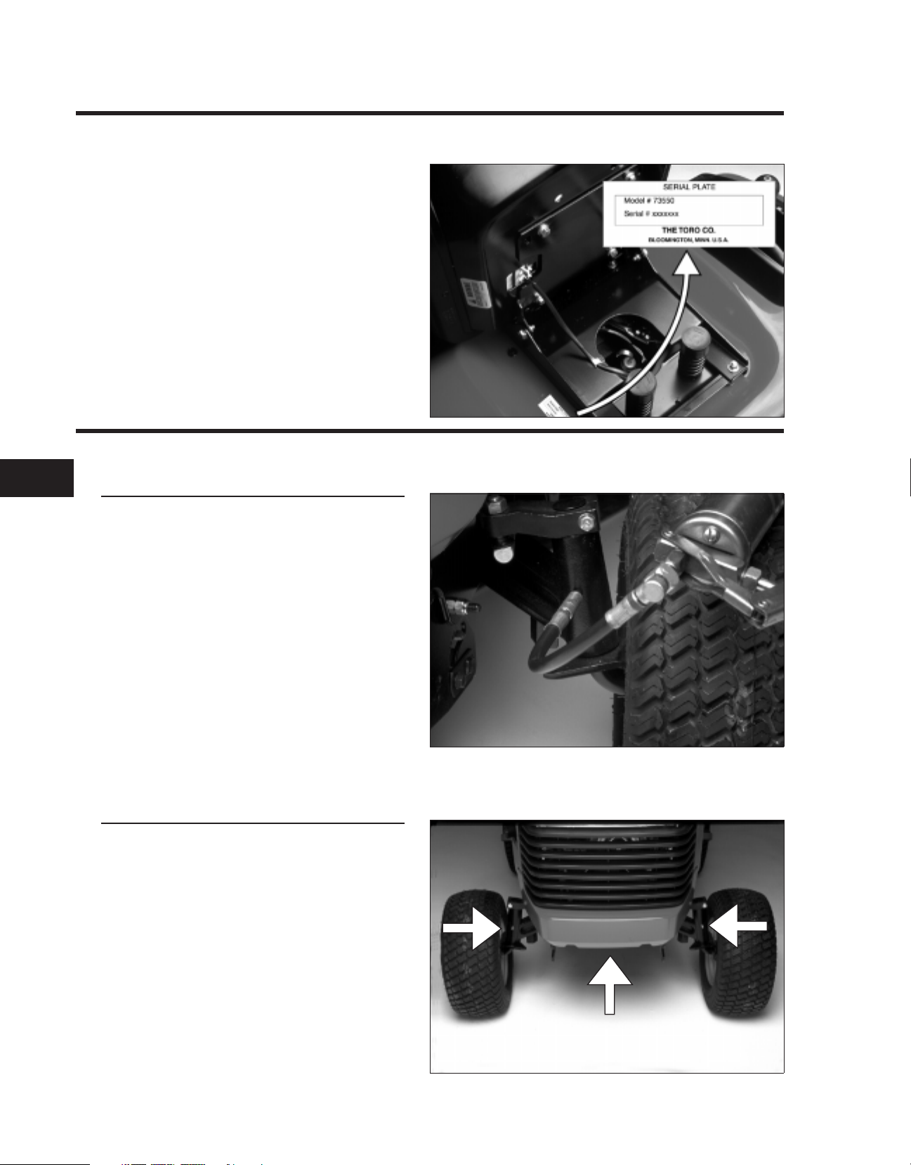
MODEL/SERIAL NUMBER LOCATION
The tractor model and serial number plate
location is shown in the illustration.
The engine has its own model and serial
number identification. Consult the appropriate
engine manufacturer’s service literature for the
location and translation of the engine model
and serial number information.
GREASING AND LUBRICATION
2.0757.015
22
Service Interval/Specification
The machine should be greased every 50 hours
or yearly, whichever occurs first. You should
grease more frequently when operating
conditions are extremely dusty or sandy. See
the maintenance table in section 1c.
Grease Type: General-purpose lithium base
grease
2.0109.033
Lubrication Points
There are 3 grease zerks on the front axle; one
on at each spindle and one at the center pivot.
2.0109.043
2-4 5xi Series Tractor Service Manual
Page 17
2.0109.026
CHASSIS
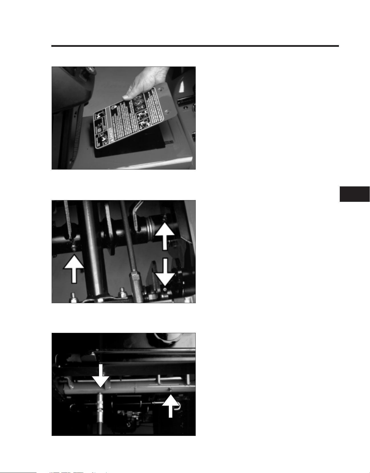
Remove the maintenance panel located in the
tunnel in front of the seat.
2.0109.024
This will allow access to the 3 zerk fittings below.
The pulley box for the mower deck contains 2
zerk fittings; one at each pulley pivot.
2
2.0144.023
5xi Series Tractor Service Manual 2-5
Page 18
CHASSIS
GREASING AND LUBRICATION (cont’d)
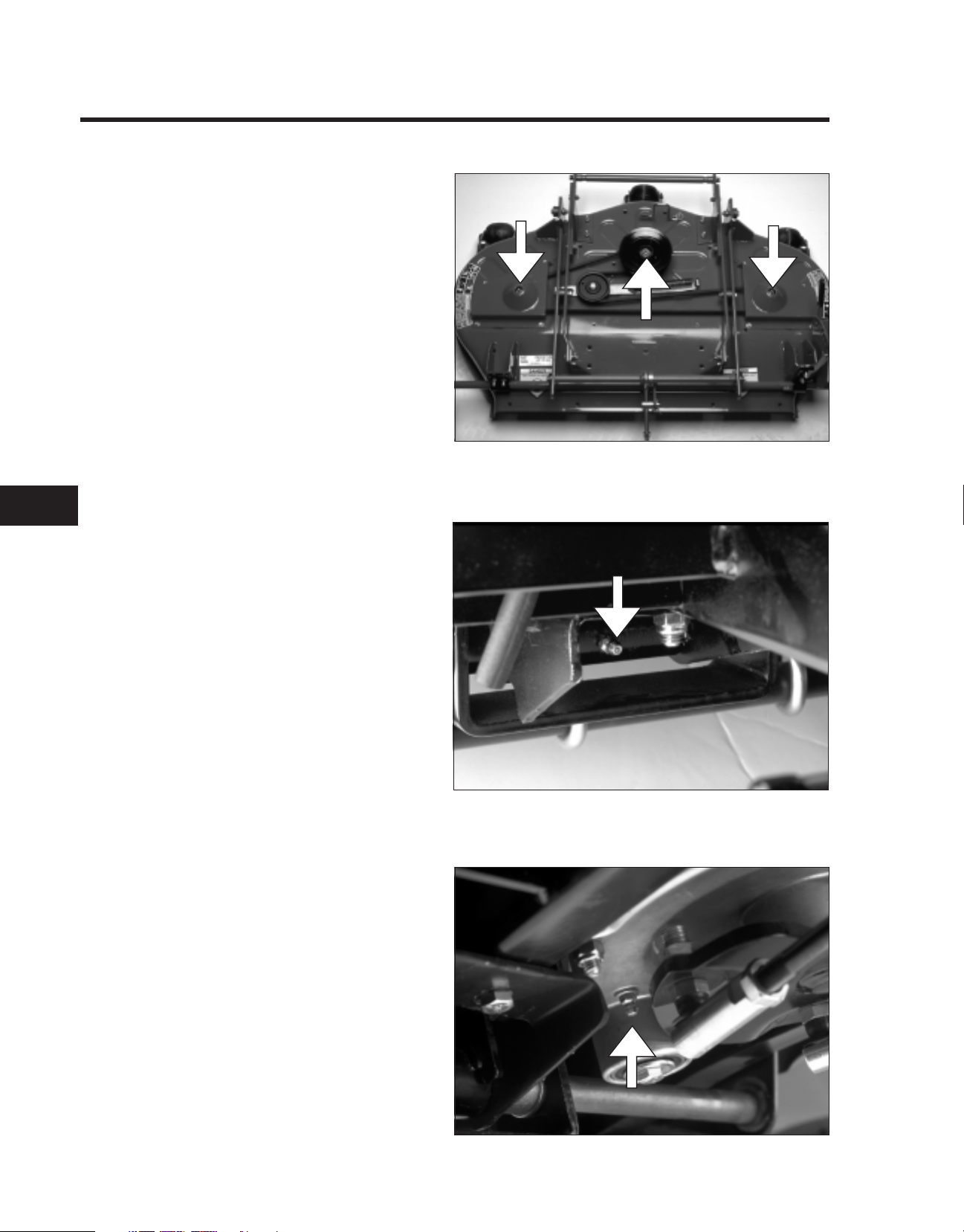
There are 3 zerk fittings located on the mower
deck spindles. Apply grease until resistance is
felt from the grease gun handle (2-3 pumps).
Also lubricate the mower deck idler arm on
decks so equipped.
The 60" deck has zerk fittings on the gage
wheels, grease every 25 hours of operation.
2.0415.001
22
There is 1 zerk fitting located on the foot pedal
shaft which requires greasing.
2.0415.012
Models with manual steering have a lubrication
point on the steering gear. Do not force
excessive amounts of grease into this fitting
(one pump of the grease gun handle only).
2.0144.069
2-6 5xi Series Tractor Service Manual
Page 19
2.0109.039
CHASSIS
REAR FENDERS, FOOTRESTS, & TUNNEL
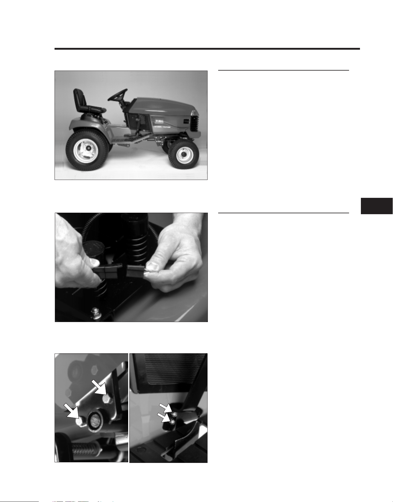
General Information
The seat, rear fenders, footrests, and tunnel can
be removed as a unit providing easy access to
chassis components.
2.0109.021
Removal
1. Disconnect the electrical connections for the
seat switch, cruise control, and taillights (as
applicable) from the wiring harness.
NOTE: The cruise control and taillights
share the same connector, which is located
under the right fender.
2. Remove the brake and motion control
pedals.
2
2.0109.003
5xi Series Tractor Service Manual 2-7
2.0109.020
Page 20
CHASSIS
REAR FENDERS, FOOTRESTS, & TUNNEL (cont’d)
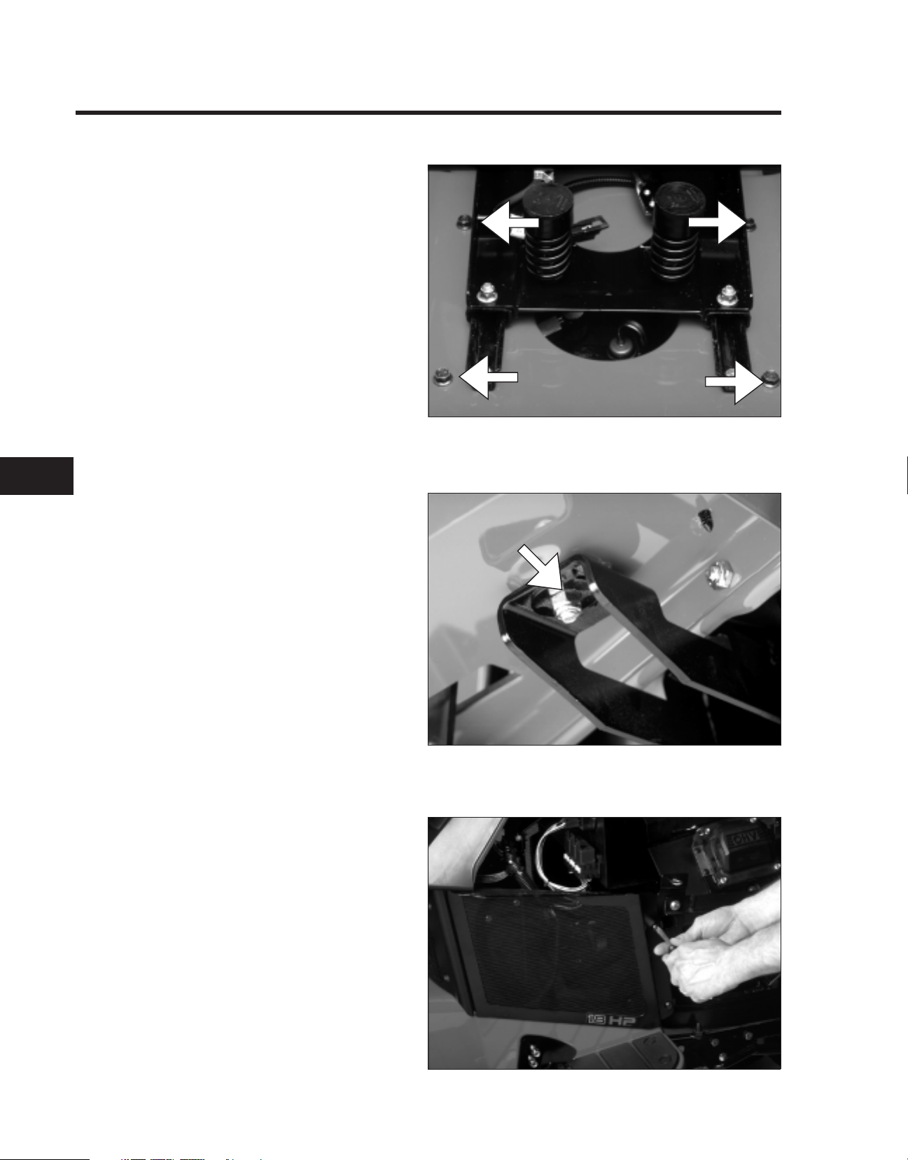
3. Remove the four bolts securing the fenders
to the frame (two on each side of the seat).
2.0109.004
22
4. Remove the nuts from the front footrest
supports and the clamps from the rear
supports.
2.0109.019
5. Remove the three air intake screens.
2.0109.015
2-8 5xi Series Tractor Service Manual
Page 21
2.0109.017
CHASSIS
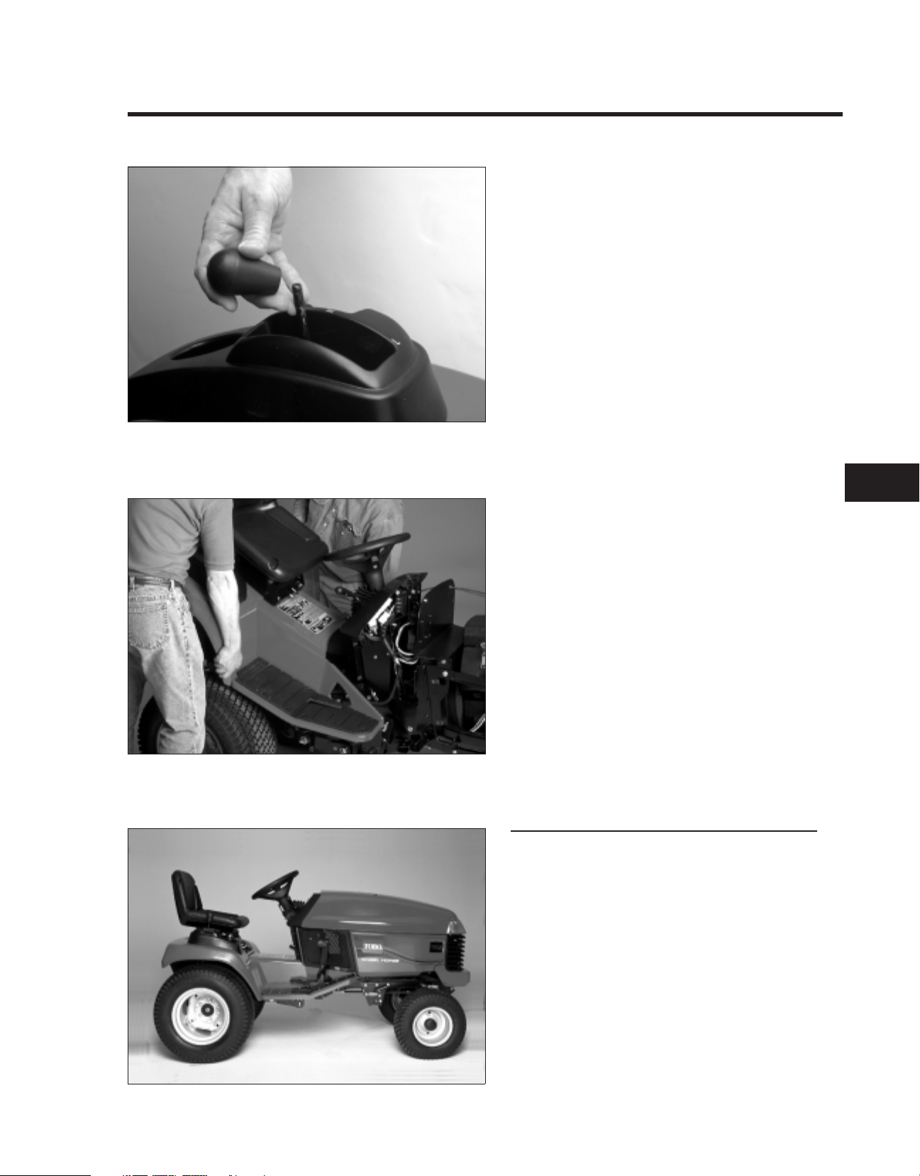
6. Remove the knob for the transaxle range
selector.
2.0109.014
7. With the help of an assistant, lift the rear of
the fender assembly until it clears the
transaxle shift lever. Then remove the
assembly to the rear of the tractor.
Reassembly
Reverse steps 1-7 to reassemble the seat, rear
fenders, footrests, and tunnel.
NOTE: Failure to keep all hoses in place on the
top of the fuel tank could result in improper
operation of the fuel vent or supply system.
2
NOTE: Do not pinch any wiring between the
fender assembly and the top edges of the frame.
2.0109.039
5xi Series Tractor Service Manual 2-9
Page 22
CHASSIS
FRONT WHEEL TOE-IN
Specification/Service Interval
If there is uneven tire wear, lawn scuffing, or
hard steering, toe-in may need to be adjusted.
Toe-in should be 1/8" - 1/4" (3 to 6 mm) on the
front wheels. This should be checked every
100 hours or once a year, whichever occurs first.
2.0109.043
22
Measurement
1. Disengage the PTO, set the parking brake,
and turn the ignition key to OFF to stop the
engine. Remove the key.
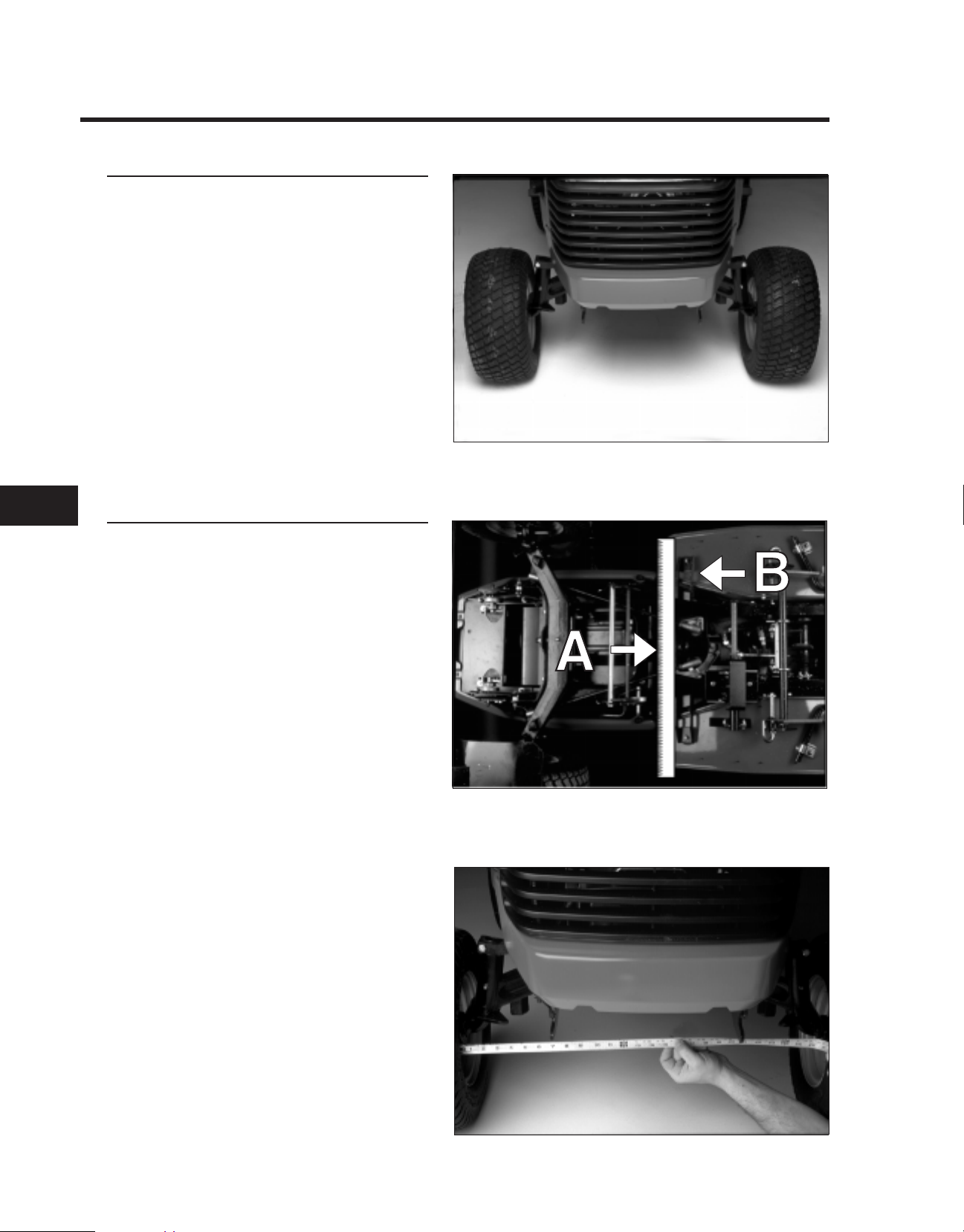
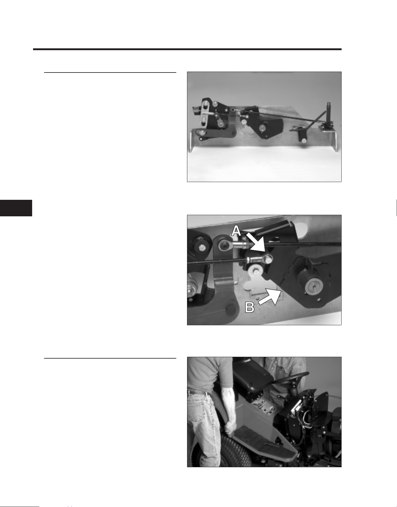
2. Turn wheels straight ahead. Square the
lower steering plate to the center line of the
frame rails by aligning a straight edge (A)
with the footrest support (B) as shown.
3. Push the front of the tires out to remove
normal looseness in the linkage.
2.0144.050
4. Measure the distance between both front
tires at spindle level (at the front and rear of
the wheels).
5. The front measurement should be 1/8" to
1/4" (3 to 6 mm) less than the rear
measurement.
If adjustment is needed, follow the steps
outlined on the next page.
Note: The black steering tie rod end goes to the
front and has right hand threads.
2.0109.035
2-10 5xi Series Tractor Service Manual
Page 23
2.0109.047
CHASSIS
Adjustment
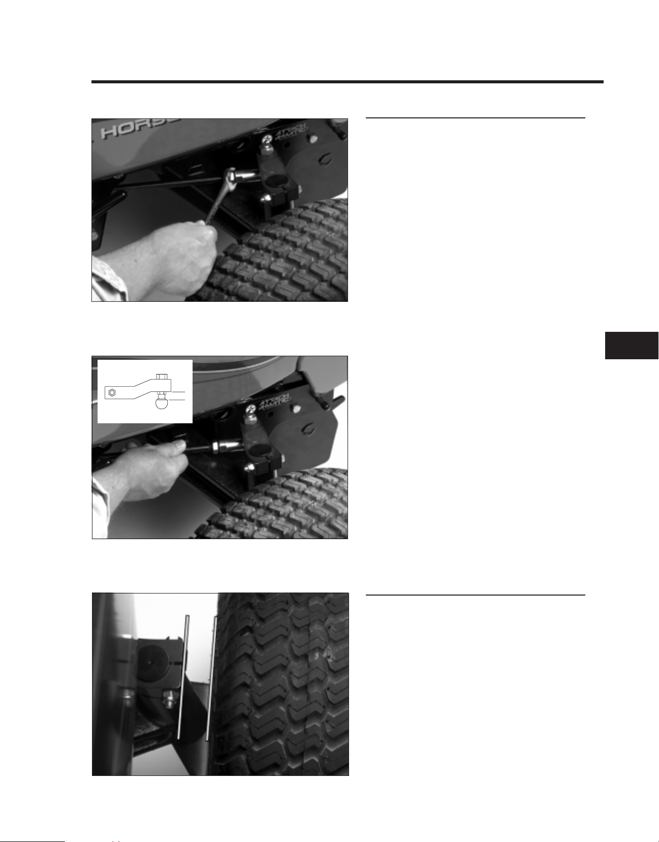
1. Loosen the jam nuts at the ends of the
steering rods.
2.0109.048
2. Rotate both steering rods equal amounts to
adjust the toe-in to 1/8" to 1/4" (3 to 6 mm) .
3. Recheck the toe-in as described earlier.
IMPORTANT: Make sure that the flat surface
on the top of the front tie rod ends are
parallel to the bottom of the steering arms
(inset).
Spindle Alignment
When installing the spindle to the steering arm,
you must align the wheel so that it is parallel to
the steering arm as shown.
2
2.0109.046
5xi Series Tractor Service Manual 2-11
Page 24
CHASSIS
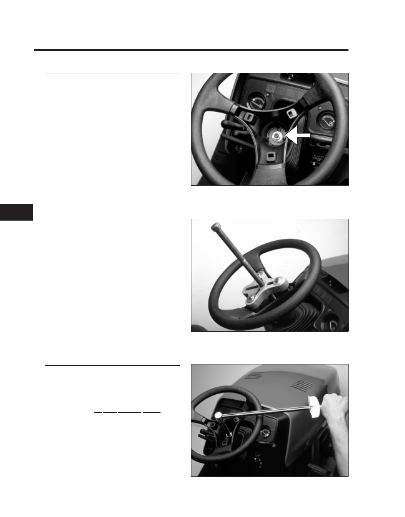
STEERING WHEEL
Remove Steering Wheel
1. Remove plastic trim cover.
2. Loosen the nut securing the wheel.
2.0144.051
22
3. Install puller as shown. Tighten forcing
screw to remove steering wheel.
NOTE: Install large flat washers on puller
bolts to protect steering wheel.
Reassembly
1. Place the steering wheel on the shaft,
carefully aligning the splines.
NOTE: On manual steering models, be sure to
align steering wheel in the “straight ahead”
position. There is
position on power steering models.
no fixed “straight ahead”
2.0144.053
2. Torque the retaining nut to 45 - 50 ft·lbs.
3. Replace the trim cover.
2.0144.052
2-12 5xi Series Tractor Service Manual
Page 25
3.7195.029
CHASSIS
POWER STEERING
General Information
The 22 HP, 20 HP liquid-cooled and 23 HP
diesel tractors are equipped with power
steering.
This system routes pressurized hydraulic fluid
supplied by the hydrostatic transmission to a
directional valve located at the base of the
steering column. When the steering wheel is
turned, this valve directs pressure to a double
acting hydraulic cylinder, causing the steering
plate to pivot as the cylinder extends or
contracts. Tie rods attached to the steering
plate turn the front spindles.
2.0109.044
When the tractor is not running, some oil will
drain from the power steering system. When
this happens, it will be necessary to purge the
air from the system. This is done by turning the
steering wheel with the engine running until the
wheels turn fully and smoothly in both
directions.
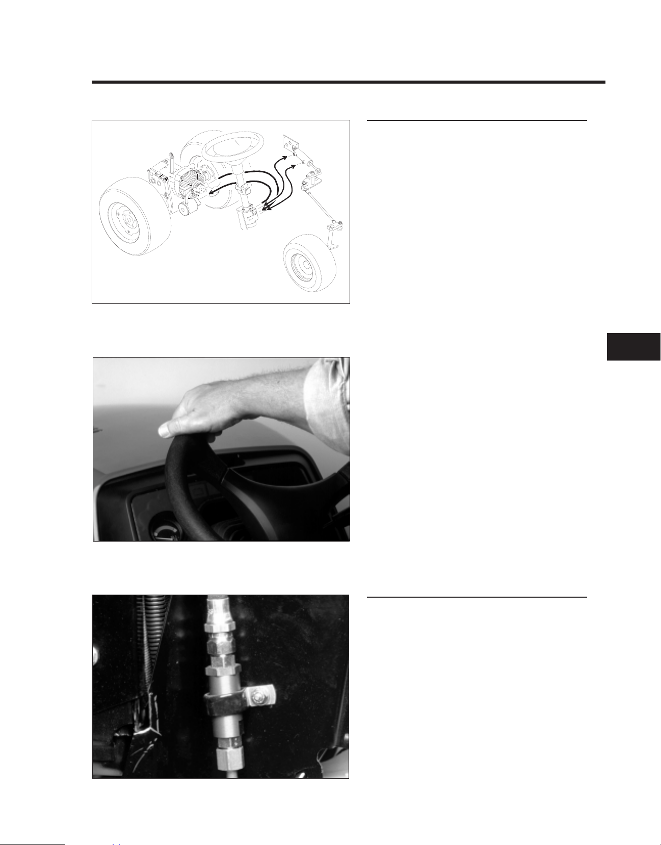
Maintenance
The power steering system is equipped with an
in-line filter screen. It should be cleaned after
initial 50 hours, then every 200 hours, or if the
power steering gets noisy.
2
To clean the power steering screen:
1. Remove the left and center air intake
screens.
2. Remove the screen housing from the clamp
securing it to the left-hand side of steering
tower.
.3. Remove the top hose first to prevent oil from
back-flushing the screen.
4. Remove the hydraulic lines, and seal the
2.0144.16
5xi Series Tractor Service Manual 2-13
ends to keep out dirt.
Page 26
CHASSIS
POWER STEERING (cont’d)
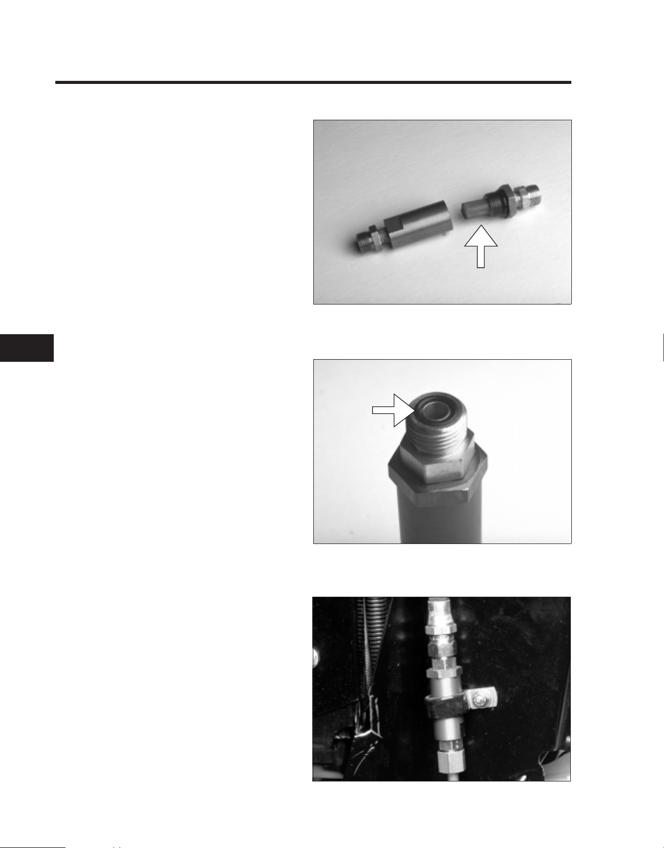
3. Disassemble the housing, and clean the
screen with solvent.
2.0144.076
22
4. Inspect the “O” rings that seal the lines and
housing. Replace them if there are any
signs of cuts or deterioration, (i.e. hardening
or swelling of the rubber).
Lubricate the “O” rings before reassembly.
2.0144.086
5. Reassemble the housing, replace the lines,
and secure to steering tower.
6. Bleed air from the system by turning the
steering wheel from stop to stop several
times.
7. Check the hydrostatic transmission
fluid level.
2.0144.16
2-14 5xi Series Tractor Service Manual
Page 27
2.3653.005
CHASSIS
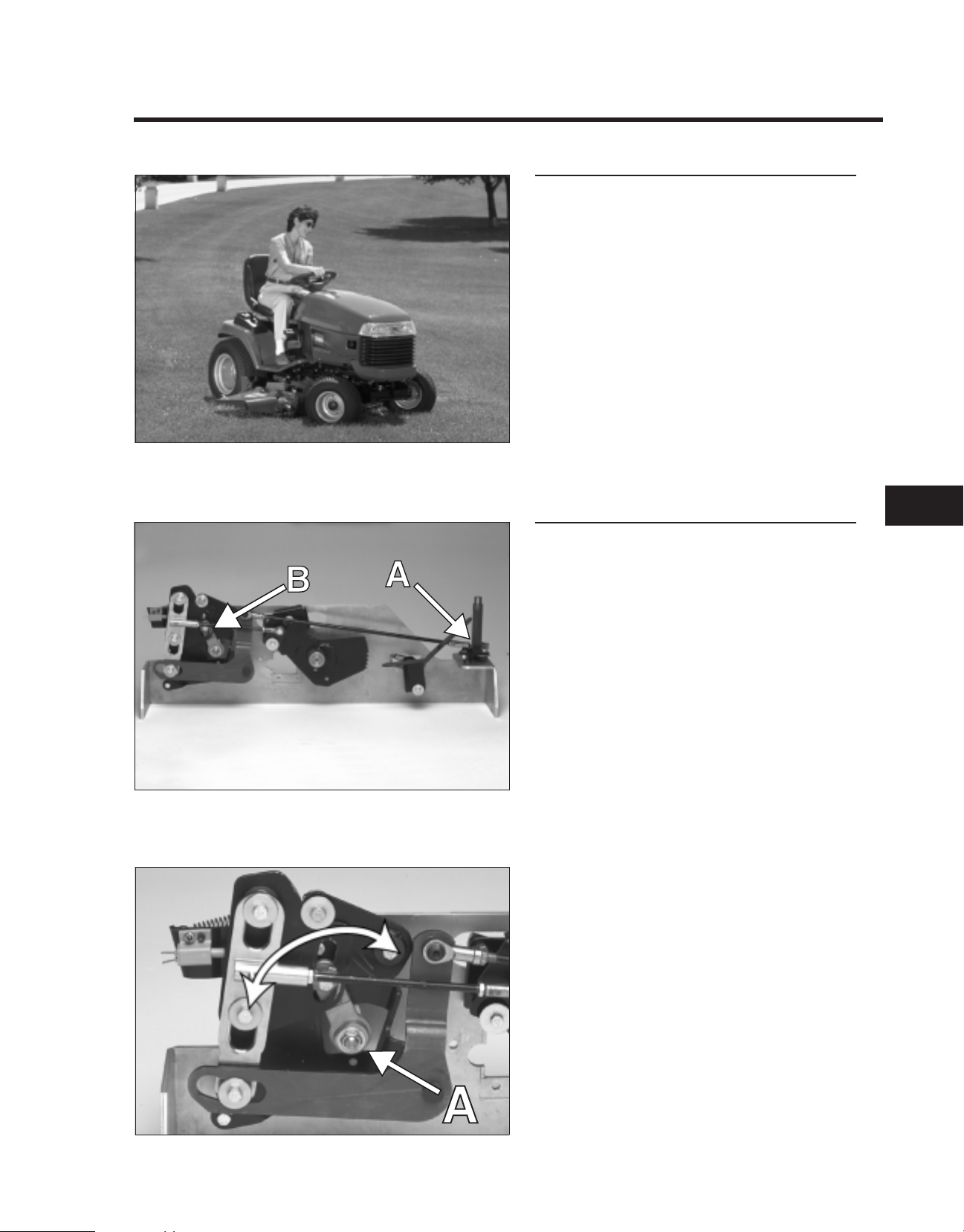
SMART TURN™ STEERING
General Information
The Smart Turn Steering™ feature automatically
lowers the speed of the tractor in tight turns.
The decrease in speed is directly proportional
to the sharpness of the turn, up to a maximum
speed reduction of approximately 40% .
The Smart Turn Steering feature permits sharp
turns to be made without always having to
change speed control position. The original
speed is restored as the turn is completed.
2.0144.059
Theory of Operation
The steering plate (A) is attached to the speed
control lever (B) on the hydrostatic transmission
through a system of linkage and levers.
When the steering wheel is turned, the linkage
pushes the speed control lever (A) on the
hydrostatic transmission towards the neutral
position and slows the tractor.
2
2.0144.63
5xi Series Tractor Service Manual 2-15
Page 28
CHASSIS
SMART TURN™ STEERING (cont’d)
Inspection
The Smart Turn Steering system was set-up at
the factory and should not need any
adjustment. Adjustment must be verified if the
transaxle is removed and reinstalled.
2.0144.059
22
Correct adjustment can be verified by checking
the position of the bushing (A) in the slot of the
brake pivot plate (B). The bushing should not
contact either side of the slot.
Correct adjustment can be verified by removing
the maintenance panel and visually checking
the position of bushing (A). It should be
centered in the slot in the brake pivot (B). The
bushing should not contact either side of the
slot when the brake is applied.
2.0144.066
Adjustments
IMPORTANT: The adjustment procedure must
be performed in the sequence given.
If adjustment of the system is necessary:
1. Remove the rear fenders and tunnel from the
tractor as outlined on page 2-7.
NOTE: It is important that the toe-in is properly
adjusted before adjusting the Smart Turn
Steering linkage. Verify setting by following the
procedure starting on page 2-10.
2.0109.014
2-16 5xi Series Tractor Service Manual
Page 29

2.0144.059
CHASSIS
2. Check the adjustment of link (A) which
connects the lower steering plate (B) to the
bell crank (C). To do this:
2.0109.043
A. Align the front wheels straight ahead so that the
front of the lower steering plate is square to the
frame rails of the tractor. Verify the alignment by
placing a straight edge across the front edge of
the lower steering plate (A), aligning it with the
foot rest support (B) as described on page 2-10.
Note: Keep wheels aligned straight ahead
except where noted.
B. Check the slider (D) making sure it is all the way
down, flush with top of spacer (E).
IMPORTANT: There must be a slight vertical
looseness (F) in the slider or there may be
binding in the pedal linkages. Lift up on the
slider to check.
2
2.0144.087
5xi Series Tractor Service Manual 2-17
Page 30

CHASSIS
SMART TURN™ STEERING (cont’d)
If the slider is not adjusted correctly,
loosen jam nuts (E), and turn the link to
adjust the length. Then tighten the jam
nuts securely.
NOTE: The front jam nut is left hand
thread, and the rear jam nut is right hand
thread.
NOTE: Jam nuts “E” are marked with
paint at the factory to discourage
unnecessary tampering.
2.0144.085
22
3. Test the adjustment of link (F) (see page
2-16). If adjustment is necessary:
A. Depress the brake. Push forward lightly
on link (F) to remove slack from the
system.
G - Rear Jam Nut (Right Hand Thread)
H - Front Jam Nut (Left Hand Thread)
I - Front Rod End Fitting
2.0144.059
Check the bushing (A) making sure it is
centered in the slot in the brake pivot plate
(B). If the bushing contacts the sides of the
slot, loosen jam nuts (G and H), and turn the
link until the bushing is centered in the slot.
2.0144.089
2-18 5xi Series Tractor Service Manual
Page 31

2.7233.073
CHASSIS
Tighten the rear jam nut first. Hold the front
rod end fitting while tightening the front jam
nut.
IMPORTANT: There must be axial
looseness in the rod (A) or there may be
binding in the pedal linkages.
2.0144.089
Test the adjustment by cycling the brake.
The slot should travel over bushing (A)
without touching.
4. Check the neutral adjustment. If the tractor
creeps in neutral, adjust the motion control
lever following the procedure on page 3-8,
Neutral Adjustment in the Hydrostatic Drive
section of this manual.
2
2.0144.072
5xi Series Tractor Service Manual 2-19
Page 32

CHASSIS
MOTION CONTROL PEDAL
Adjustment
1. Push the motion control pedal to the full
reverse position.
2. Check the clearance between the pedal
support and the reverse stop.
3. Adjust the rod as necessary to obtain the
correct clearance.
Clearance: 1/16" (1.7 mm)
TIRE PRESSURE
2.0144.034
22
Pressure: 12 psi (82.7 kPa) front and rear.
Check the tire pressure after every 25 operating
hours or monthly, whichever occurs first. Check
the tires when they are cold to get the most
accurate pressure reading.
Since tire pressure affects the position of the
mower deck, it is important to check the tire
pressure before leveling the mower and to
maintain the the correct tire pressure to
preserve the level adjustment.
2.0109.045
FUEL TANK SHUT-OFF VALVE
The fuel shut-off valve is located on the bottom
of the fuel tank.
Normally the shut-off valve is kept in the ON
position. However, if transporting the tractor on
a trailer or truck, it is good practice to place the
valve in the OFF position. Although unlikely with
this tractor’s fuel system design, closing the fuel
valve will prevent the possibility of the
carburetor flooding over while going over
bumps and filling the crankcase with gasoline.
2.0109.29
2-20 5xi Series Tractor Service Manual
Page 33

2.0109.042
CHASSIS
ELECTRIC PTO CLUTCH
General Information
The 5xi series garden tractor is equipped with a
heavy-duty electric clutch.
This clutch is maintenance free and, therefore,
requires no air gap adjustment.
Note: Troubleshooting procedures, for the
electric PTO system, are located in the
Electrical section of this manual.
If the clutch is replaced, apply high temperature
Never Seize to the crankshaft threads, use a
new thread locking patch bolt torque to
50 - 60 ft·lb (70 - 84 N·m).
2.0757.021
Break-In
The following break-in procedure must be
performed as part of predelivery service or
when a new clutch is installed.
NOTE: There must be a PTO driven attachment
installed to provide a load in order to burnish
the clutch facings properly.
NOTE: After burnish procedure is complete to
maximize deck drive life, always engage clutch
at full throttle.
1. Run the engine at full throttle and engage
the clutch bringing the load to full speed.
Then disengage the clutch.
2. Let the load come to a full stop, then engage
again.
2
3. Repeat these procedures (1 and 2) 5 times.
2.0109.022
5xi Series Tractor Service Manual 2-21
Page 34

CHASSIS
DRIVE SHAFT
General Information
Power is transmitted from the engine to the
transmission by a drive shaft running between
the frame rails.
The drive shaft is supported by two flexible
couplings located at each end.
The drive shaft assembly requires no periodic
maintenance or adjustments.
2.0144.005
22
Inspection
Visually inspect the flexible couplings for tears,
fraying, or deterioration.
2.0144.077
Assembly
1. Insert the two drive shaft retaining screws
(B) through the rear flange with the bolt
heads toward the transmission. Place the
rear flange over the woodruff key on the
transmission input shaft. Torque the
retaining bolt (A) to 90 - 120 in·lbs (122 - 163
N·m).
2. Torque the two set screws (C) to
120 - 160 in·lbs (163 - 217 N·m).
IMPORTANT: Assembly procedure must be
performed in the correct sequence.
2.3653.013
2-22 5xi Series Tractor Service Manual
Page 35

2.7162.005
CHASSIS
3. On the engine end of the driveshaft, slide
the front flange over the square key on the
engine crankshaft (A).
2.3653.011
Note: On diesel powered tractors, the key is
fitted to the flange (B). Then the flange is slid
into a hub (C) mounted to the crankshaft’s
pulley.
4. Install the four spacers through the rubber
couplings making sure they are properly
seated and squared to the coupling.
Note: The spacers with the tall heads (A)
attach the coupling to the flange on the
transmission.
2
2.3653.014
5xi Series Tractor Service Manual 2-23
Page 36

CHASSIS
DRIVE SHAFT (cont’d)
5. Install the drive shaft to the rear flange by
sliding the long head spacers over the bolts.
Torque the nuts to 170 - 220 in·lbs
(231 - 299 N·m).
2.0144.094
22
6. Align the bolt holes in the tall headed
spacers (C) in the front flexible coupling with
the bolt holes in the flange and slide flange
on shaft up to the spacers. Install the nuts,
bolts, and washers. Washer and bolt head
are against flexible coupling; nut is on back
side of flange. Then torque the bolts to
170 - 220 in·lbs (231 - 299 N·m).
7. Torque the two set screws(A) and (B) to
120 - 160 in·lbs (163 - 217 N·m).
The flex coupling should be deformed no
more than 1/8" out of flat.
2.0144.077
Rotate the drive shaft, and check for excessive
run out which can cause vibration.
2.0144.094
2-24 5xi Series Tractor Service Manual
Page 37

QUICK REFERENCE SECTION
HYDROSTATIC DRIVE
Safety Information ................................................
Specifications....................................................
Maintenance Table................................................
SERVICE SECTION
Chassis.........................................................
Hydrostatic Drive ................................................
Gasoline Engine..................................................
1a
1b
1c
2
3
4
Diesel Engine ....................................................
Electrical........................................................
5
6
5xi Series Tractor Service Manual 3-1
Page 38

HYDROSTATIC DRIVE
Table of Contents
TROUBLESHOOTING
Tractor will not operate in either direction because the
engine bogs down or stalls ............................... 3-3
Tractor goes forward only at partial speed and is slow or
does not operate in reverse............................... 3-3
Tractor will not operate in either direction. ................... 3-3
Tractor operates erratically ............................... 3-4
Tractor operates in both directions but with loss of power.
Condition becomes worse as transmission becomes hot........ 3-4
3
Transmission overheating ................................ 3-4
Abnormal vibration or noise............................... 3-4
TRANSAXLE FLUID
General Information ..................................... 3-5
Checking Fluid Level .................................... 3-5
Fluid Change .......................................... 3-6
Filter Change .......................................... 3-6
BRAKE
General Information ..................................... 3-7
Adjustment ............................................ 3-7
NEUTRAL ADJUSTMENT
General Information ..................................... 3-8
Adjustment Procedure ................................... 3-8
3-2 5xi Series Tractor Service Manual
Page 39

HYDROSTATIC DRIVE
TROUBLESHOOTING
Whenever a problem occurs with the hydrostatic drive system, you should always check
these items first:
1. Transmission oil is at proper level and air is bled from system.
2. Make sure the high-low speed lever is not in neutral.
3. Speed control linkage is functioning properly.
4. Cruise control is turned off.
Tractor will not operate in either direction because the engine bogs down
or stalls.
Possible Cause Corrective Action
Low transmission oil level Fill to full “F” mark on dipstick (when trans. is cold)
Motion control linkage Adjust, repair, or replace
The brake is sticking Repair linkage; replace brake assembly
Brake adjustment it too tight Adjust the brake
Tractor goes forward only at partial speed and is slow or does not operate
in reverse.
Possible Cause Corrective Action
The cruise control was engaged when the High-Low
range lever was in “N.”
The engine is running at partial speed Move the throttle to “FAST.”
The Linkage is out of adjustment Verify full motion is obtain on motion control shaft.
There is Internal hydro wear Repair/replace transmission
Turn the cruise control off
Adjust if necessary.
Tractor will not operation in either direction.
Possible Cause Corrective Action
The transmission oil is low Fill to full “F” mark on transmission oil dipstick when
transmission is cold
The control linkage needs adjustment or replacement Adjust, repair, or replace
The parking brake was not released or the parking
brake is not releasing
The drive shaft or wheel hub key has been damaged Replace
Faulty transmission/transaxle Repair/replace transmission/transaxle
The power steering filter is dirty Clean power steering filter
Release the parking brake or check the linkage
3
5xi Series Tractor Service Manual 3-3
Page 40

HYDROSTATIC DRIVE
TROUBLESHOOTING (cont’d)
Tractor operates erratically.
Possible Cause Corrective Action
The transmission control linkage needs adjustment or
replacement
The transmission oil level is low Fill to the full “F” mark on the transmission oil dipstick
The transmission is faulty Repair/replace
Tractor operates in both directions but with loss of power.
Condition becomes worse as transmission becomes hot.
Possible Cause Corrective Action
The transmission oil level is low Fill to the full “F” mark on the transmission dipstick
The transmission shows signs of overheating or water
contamination
The cooling fan and/or transmission cooling fins are
faulty or dirty
3
The engine is not operating at full throttle Increase the engine speed to full throttle
The power steering filter is dirty Clean the power steering filter
Adjust, repair, or replace
when transmission is cold
when transmission is cold
Replace the transmission oil and filter
Clean the transmission and/or replace the fan.
Transmission overheating.
Possible Cause Corrective Action
Not operating engine at full throttle Increase engine speed to full throttle
Low oil level Fill full “F” mark on dipstick (when trans. is cold)
Accumulation of dirt and debris on hydrostatic trans. Clean
Loose fan or broken blades Repair or replace
Abnormal vibration or noise.
Possible Cause Corrective Action
The engine mounting bolts are loose Tighten the engine mounting bolts
The idler pulley or cutter deck blade is loose Tighten the appropriate pulley
The transaxle cooling fan is loose Repair or replace as necessary
There is a problem with the electric clutch Repair or replace as necessary
3-4 5xi Series Tractor Service Manual
Page 41

2.0144.029
HYDROSTATIC DRIVE
TRANSAXLE FLUID
General Information
All models of the 5xi series tractor are equipped
with the Toro Wheel Horse transaxle with the
Eaton model 11 hydrostatic transmission. The
transmission is equipped with a charge pump
which supplies hydraulic pressure to operate
the attachment lift and power steering on units
so equipped . The charge pump also provides
pressurized fluid to the transmission pump to
make up for normal internal leakage.
FLUID TYPE: SAE 10W-30 detergent oil
(API service SH or higher).
Checking Fluid Level
2.0757.015
1. The transaxle fluid level must be checked
when the machine is
level surface.
2. Tilt the seat forward.
3. Clean around the dipstick to prevent dirt
from falling into the system when the
dipstick is removed.
NOTE: Allowing dirt in the reservoir may
result in severe damage to the transmission.
4. Remove the dipstick. If necessary, add oil to
the Full line on the dipstick.
IMPORTANT: Do not fill the reservoir above
the FULL line as the reservoir may overflow
during use.
cold and parked on a
3
2.0109.007
5xi Series Tractor Service Manual 3-5
Page 42

HYDROSTATIC DRIVE
TRANSAXLE FLUID (cont’d)
Fluid Change
The hydrostatic fluid should be changed every
200 hours of operation.
Remove the drain plug and drain the transaxle
fluid into a suitable container.
Replace the drain plug, and fill the transaxle to
the FULL mark with 10W-30 detergent oil with
an API service rating of SH or higher.
System Capacity (refill capacity is 4.5 quarts):
With power steering: 7 qts. (6.6 l)
Without power steering: 6 qts. (5.6 l)
Filter change
2.0415.004
3
The transaxle is equipped with a 10 micron
spin-on oil filter. This filter should be changed
after the first 50 hours of operation and then
every 200 hours thereafter.
2.0144.031
When replacing the filter, coat the gasket with
transaxle fluid. Tighten until the gasket contacts
the base, then an additional 1/2 turn.
2.0144.014
3-6 5xi Series Tractor Service Manual
Page 43

3.7197.067
HYDROSTATIC DRIVE
BRAKE
General Information
The 5xi series series tractor is equipped with an
external band parking brake which is located on
the right side of the transaxle.
When the brake pedal is pressed, the linkage
returns the transmission to neutral, then applies
the brake.
The primary function of the brake is to keep the
tractor from rolling after it has been stopped. It
can also be locked in the applied position and
serves as the parking brake.
Adjustment
2.0109.005
1. Place the transmission in neutral.
2. Depress the brake pedal. There should be 2"
(51 mm) of free travel.
4. Turn the adjustment nut until the above
condition is met.
CAUTION: Do not overtighten the
adjustment nut.
3
2.0109.010
5xi Series Tractor Service Manual 3-7
Page 44

HYDROSTATIC DRIVE
NEUTRAL ADJUSTMENT
General Information
The hydrostatic transmission linkage is
designed to be self-centering or “return to
neutral”. If the wheels continue to drive with no
pressure on the control pedal (tractor creeps),
neutral adjustment is required.
CAUTION: The hydrostatic cooling fan
will be spinning. Use extreme caution to
avoid making contact with the fan while
performing this adjustment.
Adjustment Procedure
2.0144.001
3
1. Bring the hydrostatic transmission up to
operating temperature.
2. Place the rear axle on jack stands, and
remove the rear wheels.
NOTE: Do not set the parking brake.
2.3653.006
3. To gain access to the adjustment eccentric,
turn the front wheels in either direction to the
steering stop.
2.0144.072
3-8 5xi Series Tractor Service Manual
Page 45

2.0144.072
HYDROSTATIC DRIVE
4. Loosen the through bolt just enough to allow
rotation of the eccentric (A).
2.0144.071
5. With the engine running, rotate the eccentric
until the right rear wheel hub begins to turn.
Note the position of the eccentric. Rotate the
eccentric in the opposite direction until the
wheel hub again begins to turn.
6. Center the eccentric between these points,
and tighten the through bolt while holding
the eccentric.
NOTE: Do not turn the eccentric more than
90° in either direction. Notch in eccentric
must be away from pivot point of control arm.
3
2.144.72
5xi Series Tractor Service Manual 3-9
Page 46

QUICK REFERENCE SECTION
GASOLINE ENGINE
Safety Information ................................................
Specifications....................................................
Maintenance Table................................................
SERVICE SECTION
Chassis.........................................................
Hydrostatic Drive .................................................
Gasoline Engine .................................................
1a
1b
1c
2
3
4
Diesel Engine ....................................................
Electrical........................................................
5
6
5xi Series Tractor Service Manual 4-1
Page 47

GASOLINE ENGINE
TROUBLESHOOTING
Engine cranks but will not start . . . . . . . . . . . . . . . . . . . . . . . . . . . . . . . 4 - 3
Starter does not crank . . . . . . . . . . . . . . . . . . . . . . . . . . . . . . . . . . . . . . 4 - 3
Engine starts but does not keep running. . . . . . . . . . . . . . . . . . . . . . . . 4 - 3
Engine is difficult to start . . . . . . . . . . . . . . . . . . . . . . . . . . . . . . . . . . . . 4 - 3
Engine runs but knocks or misses. . . . . . . . . . . . . . . . . . . . . . . . . . . . . 4 - 4
Engine will not idle . . . . . . . . . . . . . . . . . . . . . . . . . . . . . . . . . . . . . . . . . 4 - 4
Engineoverheats..........................................4-4
Engine loses power . . . . . . . . . . . . . . . . . . . . . . . . . . . . . . . . . . . . . . . . 4 - 4
Table of Contents
4
Engineknocks ............................................4-4
AIR CLEANER
Service Interval/Specification . . . . . . . . . . . . . . . . . . . . . . . . . . . . . . . . . 4 - 5
Cleaning . . . . . . . . . . . . . . . . . . . . . . . . . . . . . . . . . . . . . . . . . . . . . . . . . 4 - 5
ENGINE OIL
Service Interval . . . . . . . . . . . . . . . . . . . . . . . . . . . . . . . . . . . . . . . . . . . . 4 - 6
Changing/Draining . . . . . . . . . . . . . . . . . . . . . . . . . . . . . . . . . . . . . . . . . 4 - 6
OIL FILTER
Service Interval/Specification . . . . . . . . . . . . . . . . . . . . . . . . . . . . . . . . . 4 - 6
Changing ................................................4-7
SPARK PLUG
Specification/Service Interval . . . . . . . . . . . . . . . . . . . . . . . . . . . . . . . . . 4 - 7
Installation. . . . . . . . . . . . . . . . . . . . . . . . . . . . . . . . . . . . . . . . . . . . . . . . 4 - 8
FUEL FILTER
Service Interval . . . . . . . . . . . . . . . . . . . . . . . . . . . . . . . . . . . . . . . . . . . . 4 - 8
COOLING SYSTEM, AIR
General Information . . . . . . . . . . . . . . . . . . . . . . . . . . . . . . . . . . . . . . . . 4 - 8
Maintenance . . . . . . . . . . . . . . . . . . . . . . . . . . . . . . . . . . . . . . . . . . . . . . 4 - 9
COOLING SYSTEM, LIQUID
General Information . . . . . . . . . . . . . . . . . . . . . . . . . . . . . . . . . . . . . . . . 4 - 9
Maintenance . . . . . . . . . . . . . . . . . . . . . . . . . . . . . . . . . . . . . . . . . . . . . 4 - 10
4-2 5xi Series Tractor Service Manual
Page 48

GASOLINE ENGINE
TROUBLESHOOTING
Engine cranks but will not start.
Possible Cause Corrective Action
Incorrect starting procedure Ensure throttle is at full, and choke is on
The fuel tank is empty Fill with fresh fuel
The fuel shut-off valve is closed Open fuel shut-off valve
Dirt or water is in the fuel system Drain and flush fuel system; add fresh fuel
Clogged fuel line Clean or replace
The spark plug lead is disconnected Reconnect spark plug
The kill relay not energized Inspect safety switches and wiring
A spark plug is faulty Replace spark plug
Faulty ignition module Replace ignition module
Starter does not crank.
Possible Cause Corrective Action
Blown or loose fuse Determine cause, correct and replace fuse
Battery is discharged Charge battery or replace if necessary
Safety interlock system malfunctioning Inspect safety switches and wiring harness
Faulty starter or starter solenoid Replace
Seized internal engine components Replace
Poor ground; loose connections Clean and tighten
Engine starts but does not keep running.
4
Possible Cause Corrective Action
Misadjusted or faulty choke or throttle control cable Adjust or replace
The fuel tank vent is restricted Vent system hoses kinked or plugged, clean or repair
Dirt or water in the fuel system Drain and flush fuel system; add fresh fuel
The fuel filter is clogged Replace the fuel filter
The fuel pump is faulty Repair or replace
The carburetor is faulty Clean or rebuild
Loose wires or poor connections Check and tighten wire connections
The cylinder head gasket is faulty Replace
Engine is difficult to start.
Possible Cause Corrective Action
Improper starting procedure Ensure throttle is at full, and choke is on
Dirt or water in the fuel system Drain and flush fuel system, add fresh fuel
Clogged fuel filter Replace
Loose wires or poor connections Troubleshoot and repair
Misadjusted or faulty choke or throttle control cable Adjust or replace
Faulty spark plug Replace
Low compression Test compression, correct as needed
5xi Series Tractor Service Manual 4-3
Page 49

GASOLINE ENGINE
TROUBLESHOOTING (cont’d)
Engine runs but knocks or misses.
Possible Cause Corrective Action
Dirt, water, or stale fuel is in the fuel system Drain and flush the fuel system; add fresh fuel
A spark plug lead is loose Reconnect the spark plug lead
A spark plug is faulty Replace the spark plug
Loose wires or poor connections Check and tighten wire connections
Engine overheating See ENGINE OVERHEATS
Engine will not idle.
Possible Cause Corrective Action
The fuel tank is restricted Check hoses, clean or replace
Dirt or water is in the fuel system Drain and flush fuel system; add fresh fuel
A spark plug is faulty Replace the spark plug
Carburetor idle passages are plugged Clean or replace carburetor
The Idle speed adjusting screw is incorrectly set Reset to factory specifications
The fuel pump is faulty Repair or replace
Low compression Test compression, correct as needed
Engine overheats.
Possible Cause Corrective Action
4
(3) air intake screens are dirty Clean with every use
Restricted air flow into the engine or radiator
The crankcase oil level is incorrect Fill or drain to the full mark
The fuel mixture is lean Clean carburetor, check float level, and inspect main jet
Excessive loading Reduce load; use lower ground speed
Defective thermostat Replace the thermostat
More coolant is needed Check and add coolant
Inspect & clean the (3) air intake screens & radiator screen
Engine loses power.
Possible Cause Corrective Action
The crankcase oil level is incorrect Fill or drain to the full mark
The air cleaner element is dirty Clean or replace
Dirt, water, or stale fuel is in the fuel system Drain and flush fuel system; add fresh fuel
The engine is overheated See ENGINE OVERHEATS
A spark plug is faulty Replace the spark plug
Low compression Test compression, correct as needed
Engine knocks.
Possible Cause Corrective Action
Old or improper fuel Drain system and add fresh fuel
Internal wear or damage Inspection required
4-4 5xi Series Tractor Service Manual
Page 50

2.7146.035
GASOLINE ENGINE
AIR CLEANER
Service Interval/Specification
Foam Element (A): Clean and re-oil after every
25 operating hours, or yearly, whichever occurs
first.
Paper Element (B): Replace after every 100
operating hours or yearly, whichever comes first.
NOTE: Service the air cleaner more frequently
(every few hours) if operating conditions are
extremely dusty or sandy.
Cleaning
2.0144.019
FOAM ELEMENT
1. Wash the foam element in liquid soap and
warm water. When the element is clean,
rinse it thoroughly.
2. Dry the element by squeezing it in a clean
cloth.
3. Put one or two ounces of oil in the element.
Squeeze the element to distribute the oil.
IMPORTANT: Replace the foam element if it
is torn or worn.
PAPER ELEMENT
1. Lightly tap the element on a flat surface to
remove dust and dirt.
2. Inspect the element for tears, an oily film, or
damage to the rubber seal.
4
IMPORTANT: Never clean the paper
element with pressurized air or liquids, such
as solvent, gasoline, or kerosene. Replace
the paper element if it is damaged or
defective.
2.0144.099
5xi Series Tractor Service Manual 4-5
Page 51

GASOLINE ENGINE
ENGINE OIL
Service Interval
Oil Type: Detergent oil (API service SH or
higher).
Crankcase capacity (with filter): 3.8 pt. (1.8 l).
Viscosity: See table.
Change oil:
• After first 5 operating hours.
4
• After every 100 operating hours.
Changing/Draining
1. Run the engine for five minutes.
2. Park the machine so the drain side is slightly
lower than the opposite side. Set the parking
brake and turn the engine off.
3. Slide a piece of 1/2" (12 mm) hose over the
oil drain.
4. Open the drain by turning it clockwise 1/8
turn and pull it out.
5. Let oil drain completely. Close drain.
6. Refill with recommended oil.
-20 0 2032406080100
F
-30 -20 -10 0 10 20 30 40
C
3.7197.079
2.0144.054
OIL FILTER
Service Interval/Specification
Replace the oil filter every 200 hours or every
other oil change.
NOTE: Change the oil filter more frequently
when operating conditions are extremely dusty.
2.0144.092
4-6 5xi Series Tractor Service Manual
Page 52

3.0144.014
GASOLINE ENGINE
Changing
1. Drain the oil from the engine.
2. Remove the old filter and wipe the filter
adapter gasket surface.
3. Apply a thin coat of new oil to the rubber
gasket on the replacement filter.
4. Install the new filter to the filter adapter.
Turn the filter clockwise until the gasket
contacts the filter adapter, then tighten the
filter an additional 1/2 turn.
5. Fill the crankcase with the proper oil.
SPARK PLUG
Service Interval/Specification
2.0144.040
Kohler Engines
Type: Champion RC12YC (or equivalent)
Air Gap: 0.030 in (.76 mm)
Kawasaki Engines
Type: NGK BMR4A
Air Gap: .024 - .028 in (0.6 - 0.7 mm)
Install new spark plugs after every 100
operating hours/Kawasaki, 200 hours/Kohler.
Check the spark plugs after every 25 operating
hours. Make sure the air gap is correct before
installing the the spark plug.
If the insulator on the spark plug is light brown
or gray, the engine is running properly. A black
coating on the insulator indicates the air cleaner
may be dirty.
IMPORTANT: Never clean the spark plugs.
Always replace the spark plugs when it has a
black coating, worn electrodes, an oily film, or
cracks.
4
2.0144.011
5xi Series Tractor Service Manual 4-7
Page 53

GASOLINE ENGINE
SPARK PLUG (cont’d)
Installation
Install the spark plugs and metal washer. Make
sure the air gap (.028) is set correctly. Torque
the spark plugs to specifications.
Spark plug torque:
Kohler engines 18-22 ft·lbs (24-30 N·m)
Kawasaki engines 18 ft·lbs (25 N·m)
FUEL FILTER
Service Interval
2.0144.048
Replace the fuel filter after every 100 operating
hours or yearly, whichever occurs first.
4
COOLING SYSTEM, AIR
General Information
Models 518xi, 520xi, and 522xi are equipped
with air-cooled engines.
The engine is cooled by air drawn through the
air intake screen by a fan attached to the
flywheel. Engine heat is carried away when
shrouds attached to the engine direct the air
flow through fins located on the cylinders and
cylinder heads.
2.0144.092
2.0109.40
4-8 5xi Series Tractor Service Manual
Page 54

2.0415.008
GASOLINE ENGINE
Maintenance
Inspect air intake screens often. Keep cooling
and combustion air paths free of debris at all
times.
Consult the engine manufacturer’s service
manual for specific instructions and service
intervals.
NOTE: Operating the engine with a blocked air
intake screen, dirty or plugged cooling fins,
and/or cooling shrouds removed, will cause
engine damage due to overheating.
It is preferable to blow dirt out, rather than
washing it out. If water is used, keep it away
from electrical items.
COOLING SYSTEM, LIQUID
General Information
2.7163.09
Models 520Lxi are equipped with a
liquid-cooled engine.
This engine uses a gear driven water pump to
circulate coolant through passages in the
engine block and cylinder heads. The coolant
carries engine heat to a radiator which transfers
the heat stored in the coolant to the
surrounding air by drawing the cooler ambient
air through fins in the radiator with a belt driven
fan.
Engine temperature is maintained by a
thermostat which opens at approximately 150°
F (66° C). When the thermostat is open, it
allows coolant to flow through the radiator.
When the coolant temperature falls below 150°
F (66° C) the thermostat closes, bypassing the
radiator allowing faster warm-up and consistent
operating temperature.
4
The cooling system is pressurized at operating
temperature to prevent evaporation and raise
the boiling point of the coolant .
2.7163.013
5xi Series Tractor Service Manual 4-9
Page 55

GASOLINE ENGINE
COOLING SYSTEM, LIQUID (cont’d)
Maintenance
Inspect the cooling system often. Carefully
clean grass clippings and other debris from air
intake screens and radiator fins.
2.0144.012
4
Maintain coolant level in the coolant recovery
tank between two lines on reservoir bottle with a
50/50 mix of antifreeze and water.
Caution: Do not remove the radiator cap
when the engine is hot. Discharge of hot
coolant can cause severe burns.
2.0144.049
Inspect coolant hoses and fan belt for
deterioration every 100 hours of operation.
Replace when deterioration is noted.
Watch for signs of leaks such as rust streaks or
puddles of coolant under the tractor.
Change engine coolant according to the service
interval and instructions in the engine
manufacturer’s service manual.
2.0144.039
4-10 5xi Series Tractor Service Manual
Page 56

QUICK REFERENCE SECTION
DIESEL ENGINE
Safety Information ................................................
Specifications....................................................
Maintenance Table................................................
SERVICE SECTION
Chassis.........................................................
Hydro Drive .....................................................
Gasoline Engine ................................................
1a
1b
1c
2
3
4
Diesel Engine .................................................
Electrical........................................................
55
6
5xi Series Tractor Service Manual 5-1
Page 57

DIESEL ENGINE
TROUBLESHOOTING
Engine cranks but will not start . . . . . . . . . . . . . . . . . . . . . . . . . . . . . . . 5 - 3
Starter does not crank . . . . . . . . . . . . . . . . . . . . . . . . . . . . . . . . . . . . . . 5 - 3
Engine starts but does not keep running. . . . . . . . . . . . . . . . . . . . . . . . 5 - 3
Engine is difficult to start . . . . . . . . . . . . . . . . . . . . . . . . . . . . . . . . . . . . 5 - 4
Engine runs but knocks and misses . . . . . . . . . . . . . . . . . . . . . . . . . . . 5 - 4
Engine will not idle . . . . . . . . . . . . . . . . . . . . . . . . . . . . . . . . . . . . . . . . . 5 - 4
Engineoverheats..........................................5-4
Engine loses power . . . . . . . . . . . . . . . . . . . . . . . . . . . . . . . . . . . . . . . . 5 - 4
Table of Contents
5
Engineknocks ............................................5-5
Excessive black smoke from exhaust . . . . . . . . . . . . . . . . . . . . . . . . . . 5 - 5
Excessive white smoke from exhaust . . . . . . . . . . . . . . . . . . . . . . . . . . 5 - 5
AIR CLEANER
Service Interval/Specification . . . . . . . . . . . . . . . . . . . . . . . . . . . . . . . . . 5 - 6
Cleaning . . . . . . . . . . . . . . . . . . . . . . . . . . . . . . . . . . . . . . . . . . . . . . . . . 5 - 6
ENGINE OIL
Service Interval . . . . . . . . . . . . . . . . . . . . . . . . . . . . . . . . . . . . . . . . . . . . 5 - 6
Changing/Draining . . . . . . . . . . . . . . . . . . . . . . . . . . . . . . . . . . . . . . . . . 5 - 7
OIL FILTER
Service Interval/Specification . . . . . . . . . . . . . . . . . . . . . . . . . . . . . . . . . 5 - 7
Changing ................................................5-7
COOLING SYSTEM
General Information . . . . . . . . . . . . . . . . . . . . . . . . . . . . . . . . . . . . . . . . 5 - 8
Maintenance . . . . . . . . . . . . . . . . . . . . . . . . . . . . . . . . . . . . . . . . . . . . . . 5 - 8
ENGINE MOUNTS
EngineMounting ..........................................5-9
FUEL SYSTEM
Fuel Filter . . . . . . . . . . . . . . . . . . . . . . . . . . . . . . . . . . . . . . . . . . . . . . . . 5 - 9
GLOW PLUGS
Cold Start Up . . . . . . . . . . . . . . . . . . . . . . . . . . . . . . . . . . . . . . . . . . . . 5 - 10
5-2 5xi Series Tractor Service Manual
Page 58

DIESEL ENGINE
TROUBLESHOOTING
Warning: Diesel fuel under high pressure. Cover fittings before loosening. High pressure fuel can
penetrate skin causing blood poisoning or infection.
Engine cranks but will not start.
Possible Cause Corrective Action
Contaminated fuel Clean fuel system
Incorrect starting procedure Activate glow plugs before attempting to start
The fuel tank is empty Fill with fresh fuel
The fuel shut-off valve is closed Open the fuel shut- off valve
Dirt or water is in the fuel system Drain and flush fuel system; add fresh fuel
Clogged fuel line Clean or replace
Air in fuel Bleed nozzles, check for leaks on suction side of
system
Inoperative glow plugs Check fuse, glow plugs, and wiring
Inoperative fuel solenoid Check wiring, start switch, and fuel solenoid
Slow cranking speed Check battery, oil viscosity,and starter motor
Insufficient combustion air supply Check air filter and combustion air path
Low compression Perform cylinder leak down test. Adjust, repair, or
replace affected parts.
Starter does not crank.
Possible Cause Corrective Action
The fuse is blown or loose Correct or replace the fuse
The battery is discharged Charge the battery or replace it
The safety interlock system is malfunctioning Inspect safety switches and wiring harness
A faulty starter, starter solenoid, relay, or ignition switch Replace
Seized internal engine components Replace
Engine starts but does not keep running.
Possible Cause Corrective Action
Contaminated fuel Clean fuel system
Air in fuel Bleed nozzles, check for leaks on suction side of
system
Waxing fuel below 32° F (0° C) Use a winter blend fuel when the ambient temperature
is below freezing
The fuel filter is clogged Replace the fuel filter
Dirt or water in the fuel system Drain fuel filter. Flush fuel system if necessary
The fuel tank vent is restricted Vent system hoses kinked or plugged, clean or replace
Loose wires or poor connectors Check and tighten wire connections
5
5xi Series Tractor Service Manual 5-3
Page 59

DIESEL ENGINE
TROUBLESHOOTING (cont’d)
Engine is difficult to start.
Possible Cause Corrective Action
Improper starting procedure Activate glow plugs before attempting to start
Air in fuel Bleed nozzles, check for leaks on suction side of
system
Inoperative glow plugs Check fuse, glow plugs, and wiring
Insufficient combustion air supply Check air filter and combustion air path
Faulty injection nozzles Test nozzles, clean or replace as necessary
Clogged fuel filter Replace
Incorrect injection pump timing Perform complete timing procedure
Low ambient temperature Activate block heater, check oil viscosity
Worn injection pump (hard starting warm) Check fuel supply from nozzles
Low compression Perform cylinder leakage test
Engine runs but knocks or misses.
Possible Cause Corrective Action
Air in fuel Bleed nozzles, check for leaks on suction side of
system
Dirt, water, or stale fuel in fuel system Drain and flush fuel filter; add fresh fuel
Faulty injection nozzle(s) Test nozzles, clean or replace as necessary
Low compression Perform cylinder leakage test
Engine will not idle.
5
Possible Cause Corrective Action
Air in fuel Bleed nozzles, check for leaks on suction side of
Idle speed too low Adjust idle speed
The fuel injection pump is faulty Repair or replace as necessary
The fuel tank vent is restricted Check hoses, clean, or replace
Dirt or water is in the fuel system Drain and flush fuel system; add fresh fuel
Engine overheats.
Possible Cause
(3) air intake screens are dirty Clean with every use
More coolant is needed Check and add coolant
Restricted air flow through radiator Clean debris from radiator and cooling air path
Defective thermostat Replace the thermostat
The crankcase oil level is incorrect Fill or drain to the full mark
Faulty thermostat Replace
Excessive loading Reduce load; use lower ground speed
system
Corrective Action
5-4 5xi Series Tractor Service Manual
Page 60

DIESEL ENGINE
Engine loses power.
Possible Cause Corrective Action
Insufficient combustion air supply Check air filter and combustion air path
Air in fuel Bleed nozzles, check for leaks on suction side of
system
Dirt, water, or stale fuel is in the fuel system Drain and flush fuel system; add fresh fuel
Faulty injection nozzle(s) Test nozzles, clean or replace as necessary
Incorrect injection pump timing Perform complete timing procedure
Faulty injection pump Repair or replace as necessary
Low compression Perform cylinder leakage test
The vent hole in the fuel tank vent fitting is plugged Repair or replace vent system
The engine load is excessive Reduce ground speed
The crankcase oil level is incorrect Fill or drain to the full mark
Engine knocks.
Possible Cause Corrective Action
Sticking injection nozzles Clean or replace nozzles
Incorrect injection pump timing Perform complete timing procedure
Excessive carbon build-up Clean carbon from cylinder head and piston
Internal wear or damage Inspection required
Excessive black smoke from exhaust.
Possible Cause Corrective Action
Insufficient combustion air supply Check air filter and combustion air path
Incorrect injection pump timing Perform complete timing procedure
Improper fuel Drain fuel system and refill with specified fuel
Faulty injection nozzles Clean or replace nozzles
Excessive white smoke from exhaust.
Possible Cause Corrective Action
Low engine temperature Check thermostat
Inoperative glow plugs Check fuse, glow plugs, and wiring
Faulty injection nozzles Clean or replace nozzles
Incorrect injection pump timing Perform complete timing procedure
Low compression Perform cylinder leakage test
5
5
5xi Series Tractor Service Manual 5-5
Page 61

DIESEL ENGINE
AIR CLEANER
Service Interval/Specification
Paper Element: Replace after every 100
operating hours or yearly, whichever comes first.
NOTE: Service the air cleaner more frequently
(every few hours) if operating conditions are
extremely dusty or sandy.
3.7230.079
5
ENGINE OIL
Cleaning
1. Lightly tap the element on a flat surface to
remove dust and dirt.
2. Inspect the element for tears, an oily film, or
damage to the rubber seal.
IMPORTANT: Never clean the paper
element with pressurized air or liquids, such
as solvent, gasoline, or kerosene. Replace
the paper element if it is damaged,
defective, or cannot be cleaned thoroughly.
2.3653.007
Service Interval
Oil Type: Detergent oil (API service CD or
higher).
Crankcase capacity (with filter): 3.5 Qts (3.3 l).
Viscosity: See table.
Change oil:
After first 50 operating hours.
•
After every 100 operating hours
•
-20 0 20 32 40 60 80 100
F
-30 -20 -10 0 10 20 30 40
C
3.7197.079
5-6 5xi Series Tractor Service Manual
Page 62

2.0757.008
DIESEL ENGINE
Changing/Draining
1. Run the engine for five minutes.
2. Park the machine so the drain side is slightly
lower than the opposite side. Set the
parking brake and turn the engine off.
3. Remove the drain plug.
4. Let oil drain completely. Close drain.
5. Refill to specified level with recommended
oil.
OIL FILTER
Service Interval/Specification
2.0757.038
Replace the oil filter after the first 50 hours of
operation. Then replace every 200 hours or
every other oil change.
5
Changing
1. Drain the oil from the engine.
2. Remove the old filter and wipe the filter
adapter gasket surface.
3. Apply a thin coat of new oil to the rubber
gasket on the replacement filter.
4. Install the new filter to the filter adapter.
Turn the filter clockwise until the gasket
contacts the filter adapter, then tighten the
filter an additional 1/2 turn.
5. Fill the crankcase to the specified level with
the proper oil.
2.0144.014
5xi Series Tractor Service Manual 5-7
Page 63

DIESEL ENGINE
COOLING SYSTEM
General Information
A belt driven water pump circulates coolant
through passages in the engine block and
cylinder heads. The coolant carries engine heat
to a radiator which transfers the heat stored in
the coolant to the surrounding air by drawing
the cooler ambient air through fins in the
radiator with the fan.
3.7197.100
5
Engine temperature is maintained by a
thermostat which opens at approximately 180°
F (82° C). When the thermostat is open, it
allows coolant to flow through the radiator.
When the coolant temperature falls below 180°
F (82° C), the thermostat closes, bypassing the
radiator allowing faster warm-up and consistent
operating temperature.
The cooling system is pressurized at operating
temperature to prevent evaporation and raise
the boiling point of the coolant.
2.7163.26
Maintenance
Inspect cooling system often. Carefully clean
grass clippings and other debris from air intake
screens and radiator fins.
Maintain coolant level in the coolant recovery
tank between the two lines with a 50/50 mix of
antifreeze and water.
Caution: Do not remove the radiator cap
when the engine is hot. Discharge of hot
coolant can cause severe burns.
2.0757.030
5-8 5xi Series Tractor Service Manual
Page 64

2.0757.007
DIESEL ENGINE
Inspect coolant hoses and fan belt for
•
deterioration every 400 hours or 2 years of
operation. Replace when deterioration is
noted.
Watch for signs of leaks such as rust streaks
•
or puddles of coolant under the tractor.
Change engine coolant according to the
•
service interval and instructions in the
engine manufacturer’s service manual.
ENGINE MOUNTS
Engine Mounting
2.0757.034
The diesel engine is mounted on vibration
dampening rubber isolators. Inspect these
engine mounts for damage from chemicals,
deterioration of the rubber, or loose fasteners.
5
FUEL SYSTEM
Fuel Filter
The diesel fuel system is equipped with a fuel
filter/water separator. This filter should be
replaced every 400 hours of operation. Any
water accumulation should be drained by
opening the petcock (A) before each use.
2.0757.038
5xi Series Tractor Service Manual 5-9
Page 65

DIESEL ENGINE
GLOW PLUGS
Cold Start Up
The diesel engines are equipped with glow
plugs to provide fast start-ups and minimize
white smoke from the exhaust. The glow plug
system is activated by turning the ignition
switch to the ON position. An indicator light will
go out when the engine is ready to start.
2.0757.006
5
5-10 5xi Series Tractor Service Manual
Page 66

QUICK REFERENCE SECTION
ELECTRICAL
Safety Information ................................................
Specifications....................................................
Maintenance Table................................................
SERVICE SECTION
Chassis.........................................................
Hydro Drive .....................................................
Gasoline Engine..................................................
1a
1b
1c
2
3
4
Diesel Engine ....................................................
Electrical .....................................................
5
6
5xi Series Tractor Service Manual 6-1
Page 67

ELECTRICAL
BATTERY
Service Interval/Specification.............................. 6-4
Removal .............................................. 6-4
Battery Heat Shield...................................... 6-4
Installation............................................. 6-5
Electrolyte Level ........................................ 6-5
Adding Water .......................................... 6-5
Charging .............................................. 6-6
Table of Contents
6
FUSE
General Information/Specification .......................... 6-6
HEADLIGHTS
Bulb Removal .......................................... 6-6
Bulb Installation ........................................ 6-7
INSTRUMENT PANEL LIGHTS
Bulb Removal .......................................... 6-7
Bulb Replacement ...................................... 6-7
TAILLIGHTS
Bulb Removal .......................................... 6-8
ELECTRIC CLUTCH TROUBLESHOOTING
General Information ..................................... 6-8
Coil Resistance Measurement ............................. 6-8
6-2 5xi Series Tractor Service Manual
Page 68

ELECTRICAL
SAFETY INTERLOCK SYSTEM
Purpose ...............................................6-9
Testing................................................6-9
CRUISE CONTROL
General Information ....................................6-10
Theory of Operation ....................................6-10
Troubleshooting .......................................6-11
FUEL GAUGE
General Information ....................................6-12
Theory of Operation ....................................6-12
Troubleshooting .......................................6-13
CHARGING SYSTEM
General Information ....................................6-14
Testing...............................................6-15
Voltage Regulator Replacement........................... 6-16
ELECTRICAL SCHEMATIC
518xi ................................................6-16
520/522xi .............................................6-17
520Lxi ...............................................6-18
520Dxi ...............................................6-19
6
5xi Series Tractor Service Manual 6-3
Page 69

ELECTRICAL
BATTERY
Service Interval/Specification
Check the electrolyte level in the battery every
25 hours. Always keep the battery clean and
fully charged. If the battery terminals are
corroded, clean them with a solution of four
parts water and one part baking soda. Apply a
light coating of grease to the battery terminals
to prevent corrosion.
Voltage/Cold Cranking Amps
Gasoline Engines 12V 380 CCA
Diesel Engines 12V 495 CCA
Removal
2.0109.012
6
1. Disengage the PTO, set the parking brake,
turn the ignition key to OFF and remove the
key.
2. Remove the grille.
3. Remove the battery hold down.
4. Disconnect the negative (black) ground
cable from the battery post.
5. Disconnect the positive (red) cable from the
battery post.
IMPORTANT: Always hold the battery vertical
to avoid spilling battery acid.
WARNING: When removing or installing the
battery, do not allow the battery terminals to
touch any metal parts of the tractor (below the
headlights).
2.0109.038
Battery Heat Shield
All gasoline engines are equipped with a heat
shield which is incorporated into the battery
hold down. Replace the heat shield after
servicing to protect the battery from heat.
NOTE: Failure to reinstall the heat shield after
servicing the battery can result in shortened
battery life and/or battery damage.
2.0109.016
6-4 5xi Series Tractor Service Manual
Page 70

2.0109.041
ELECTRICAL
Installation
1. Install the battery into the chassis.
2. Connect the positive (red) cable to the
positive (+) battery post.
3. Connect the negative (black) cable to the
negative (-) battery post.
4. Secure the battery with the hold down rods.
5. Install the grille.
Electrolyte Level
3.7197.111
1. With the engine off, remove the covers on
the battery.
2. The electrolyte must be up to the lower part
of the tube (A). Do not allow electrolyte to
get below the top of the plates.
3. If the electrolyte is low, add distilled water to
achieve the specified level. (See: Adding
Water)
6
Adding Water
The best time to add distilled water to the
battery is just before you operate the machine.
1. Clean the top of the battery.
2. Remove the filler caps.
3. Slowly pour distilled water into each battery
cell until the level is up to the lower part of
the tube.
IMPORTANT: Do not overfill the battery.
Electrolyte (sulfuric acid) can cause severe
corrosion and damage to the chassis.
2.0144.093
5xi Series Tractor Service Manual 6-5
4. Replace the filler caps.
Page 71

ELECTRICAL
BATTERY (cont’d)
Charging
IMPORTANT: Always keep the battery fully
charged (1.260 specific gravity). This helps
prevent battery damage when the temperature
is below 32° F (0 °C).
1. Remove the battery from the chassis.
2. Check the electrolyte level.
3. Remove the filler caps and connect a 3 to 4
amp battery charger. Charge at a rate of 4
amps (12V) or less for 4 hours. Do not
overcharge the battery. Install the filler caps
after the battery is charged.
4. Install the battery in the chassis.
FUSE
General Information/Specification
2.0144.070
The electrical system is protected by fuses. If a
fuse blows, check component/circuit for a
malfunction or short.
Fuse:
1. Main/Starter - 30 amp, blade type.
2. Alternator - 25 amp, blade type.
3. Dash, Interlock, and Cruise Control - 10
amp, blade type.
4. Headlights/Taillights - 10 amp, blade type.
6
NOTE: The number 2 fuse on diesel tractors is
for the starter and is 15 amp.
HEADLIGHTS
Bulb Removal
1. Disengage the PTO, set the parking brake,
turn the ignition key to OFF, and remove the
key.
2. Pull the wire connectors off both bulb holder
terminals.
2.7152.024
3. Rotate the bulb holder 1/4 turn
counterclockwise and remove it from the
reflector.
4. Push and rotate the bulb counterclockwise
until it stops (approximately 1/4 turn) and
remove.
2.0109.030
6-6 5xi Series Tractor Service Manual
Page 72

2.0757.031
ELECTRICAL
Bulb Installation
1. Align the pins on the bulb with the slots in
the bulb holder and insert. Push and rotate
the bulb clockwise until it stops.
2. Align the tabs on the bulb holder with the
slots in the reflector, insert and rotate 1/4
turn clockwise until it stops.
3. Push the wire connectors onto the terminals.
Bulb Number: GE 1156
INSTRUMENT PANEL LIGHTS
Bulb Removal
2.0144.024
1. Disengage the PTO, set the parking brake,
turn the ignition key to OFF, and remove the
key.
2. Turn the bulb holder 1/4 turn
counterclockwise, and remove it from the
panel
3. Pull the bulb straight out of the bulb holder.
Bulb Number: GE 194
6
Bulb Replacement
1. Align the bulb with the slot in the bulb holder
and push the bulb into the slot.
2. Align the tabs on the bulb holder with the
slots in the panel. Insert the bulb being
careful not to damage the printed circuit
connectors.
Rotate the bulb approximately 1/4 turn until it
stops.
Bulb Number: GE 194
2.0144.018
5xi Series Tractor Service Manual 6-7
Page 73

ELECTRICAL
TAILLIGHTS
Bulb Removal
1. Remove the taillight assembly from the
fender.
2. Rotate the bulb holder 1/4 turn
counterclockwise and remove it from the
housing.
3. Push and rotate the bulb counterclockwise
until it stops (approximately 1/4 turn).
Bulb Number: GE 194
ELECTRIC CLUTCH TROUBLESHOOTING
General Information
2.0757.027
6
Equipment Needed: Volt/Ohm and Ampmeter
The following troubleshooting steps will help
you determine if the clutch has failed or is the
cause of the electrical problem.
2.0144.006
Coil Resistance Measurement
Equipment: Volt/Ohmmeter
1. Disengage the PTO, set the parking brake,
turn the ignition key to OFF, and remove the
key.
2. Disconnect the clutch wire connector.
3. Set the volt/ohmmeter to check resistance
(ohms).
2.0144.080
6-8 5xi Series Tractor Service Manual
Page 74

3.7197.122
ELECTRICAL
4. Connect the meter lead wires to the wires in
the clutch connector.
The meter should read between 2.40 and
3.40 ohms. If the readings are not within
specifications, the coil has failed and the
clutch must be replaced.
If the resistance is within specifications, the
electric clutch is not the source of the
problem.
SAFETY INTERLOCK SYSTEM
Purpose
The safety interlock system is designed to
prevent the engine from starting unless:
2.0109.028
PTO
Test
Starting On On OperatorOnNo
Starting Off Off OperatorOnNo
Starting Off On Operator
Running Off Off Operator
Switch
Parking
Brake Seat
Off
Off
Expected
Result
Start
Start
No
Start
Engine
Stalls
1. You are sitting on the seat.
2. The brake pedal is depressed.
3. The power take off (PTO) is OFF.
The system will also kill the engine if you
attempt to operate the clutch or drive system
when you are not in the seat.
6
Testing
1. Set the parking brake. Move the PTO to ON.
Now turn the ignition key to START; the
engine should not crank.
2. Push the PTO to OFF and release the
parking brake. Now turn the ignition to
START; the engine should not crank.
3. Set the parking brake and move the PTO to
OFF. Start the engine. While the engine is
running, release the parking brake and rise
from the seat; the engine should stop.
5xi Series Tractor Service Manual 6-9
Page 75

ELECTRICAL
SAFETY INTERLOCK SYSTEM (cont’d)
If the system fails any of these tests, you will
need to troubleshoot the system. The 260
series Electrical Demystification Guide (form no.
492-4404) describes how to test individual
switches and circuits.
CRUISE CONTROL
General Information
3.7197.125
DEMYSTIFICATION
DEMYSTIFICATION
GUIDE
GUIDE
6
The 520xi and larger tractors are equipped with
an electric cruise control that, when activated,
locks the motion control lever in position to
maintain a constant speed. The Smart Turn
Steering system overrides the cruise control in
a sharp turn slowing the tractor until the turn is
completed. The tractor then accelerates to
resume the set speed.
2.0757.001
Theory of Operation
The cruise control is activated with a switch
located on the right side fender. When the
tractor is at the desired speed, activating the
switch energizes an electromagnet.
2.0757.004
6-10 5xi Series Tractor Service Manual
Page 76

2.0144.45
ELECTRICAL
This magnet (A) is mounted below a control
plate (B). The control plate is connected to the
speed control lever. When the cruise control is
activated, the magnet clamps the control plate
in position which holds the speed control lever
at the desired speed.
Tapping the brake pedal or shutting the switch
off deactivates the system. The foot pedal can
be used to override the cruise control; the
pre-set speed will resume when the pedal is
released.
NOTE: Activating cruise in neutral or at very
slow speeds will prevent full speed operation.
Troubleshooting
Disconnect the three pin connector from the
cruise control module. Turn the ignition switch
to the “on” position. Make sure the parking
brake is disengaged. Measure the voltage at
each of the pins in the following conditions:
Wire Color Cruise
Off
Yellow
0V 12V 12V
Cruise
On
Cruise held in
engage position
Brown 0 V 0 V 12 V
Black 0 V 0 V 0 V
If you do not get these results, the problem is in
the switches or wiring between the module and
the switches or magnet.
3.7230.132
Reconnect the three pin connector to the
module. Measure the voltage at each of the
pins on the connector in the following
conditions:
Wire Color
Yellow
Brown 0 V 0 V 0.6 to 1.3 V
Black (see
note 2
Cruise
Off
Cruise On
See note 1
Cruise held in
engage position
0 V 12 V 0.6 to 1.3 V
0V 0V 0V
If you do not get the results shown above and
have successfully completed the test described
in the test above, replace the module.
2.3653.010
Note 1:
Note 2:
Press and release brake to reset circuit .
Voltage at black wire indicates faulty ground
5xi Series Tractor Service Manual 6-11
6
Page 77

ELECTRICAL
FUEL GAUGE
General Information
The fuel gauge consists of a level indicator
(gauge) located in the instrument panel and a
sender located in the fuel tank.
6
Theory of Operation
B+ is supplied to one side of the fuel gauge.
The other side of the gauge is connected to
ground through the sender.
When the ignition switch is in the ON position,
current flow through the gauge winding causes
the needle to move. The greater the current, the
closer the needle moves to the Full mark.
2.0144.074
3.7197.133
E
2.0144.074
F
2.0144.075
6-12 5xi Series Tractor Service Manual
Page 78

ELECTRICAL
The amount of current flow is controlled by the
sender which consists of a rheostat connected
F
E
to a float mounted in the fuel tank. When the
tank is Full, the float is high and the resistance
of the rheostat is low, allowing more current
flow which moves the needle to the Full mark.
2.0144.084
3.7197.134
E
2.0144.074
F
As fuel is consumed, the float moves down
increasing the resistance and allows less
current flow. This causes the needle to move
toward empty.
6
Troubleshooting
If the fuel gauge is inoperative:
1. Disconnect the wire from the sender. When
the circuit is open (no current flow), the
gauge should read empty.
2.0144.083
2.0144.075
5xi Series Tractor Service Manual 6-13
Page 79

ELECTRICAL
FUEL GAUGE (cont’d)
2. Connect the wire to ground (maximum
current). The gauge should read Full.
If conditions 1 and 2 are not met, the
problem is in the wiring or the gauge.
If conditions 1 and 2 above are met, the
problem is with the sender.
To test the sender:
1. Remove the sender from the fuel tank.
2. Connect an ohmmeter from the wire terminal
to the sender body (ground).
3. Move the float through its travel. The
resistance should range from 20-35 ohms
when the float is up. When the float is all the
way down, the resistance should be 240-265
ohms.
6
CHARGING SYSTEM
General Information
2.0144.056
2.0144.015
2.0144.075
All gasoline fueled tractor charging systems
consist of a permanent magnet flywheel
alternator and a separate voltage
regulator/rectifier.
The air-cooled Kohler engines have a 15 amp
charging system.
The regulator on these units is mounted on the
engine.
2.0757.028
6-14 5xi Series Tractor Service Manual
Page 80

2.0757.011
ELECTRICAL
Tractors powered by liquid-cooled Kawasaki
engines have a 20 amp alternator.
The voltage regulator on these units is mounted
to the tractor.
2.0144.032
Diesel tractors are equipped with a belt driven
alternator with an integral voltage regulator.
6
Testing
Connect a voltmeter across the battery. The
voltage should read between 13.8 -14.2 VDC at
3400 RPM with the lights on. If the voltage is
low or you suspect a charging system fault,
follow the troubleshooting instructions in the
engine manufacturer’s service manual.
2.0144.056
5xi Series Tractor Service Manual 6-15
Page 81

ELECTRICAL
CHARGING SYSTEM (cont’d)
Voltage Regulator Replacement
On air-cooled engines, it is necessary to raise
the voltage regulator side of the engine
(right-hand side) to provide clearance for
removal of the voltage regulator. Remove the
two engine mounting bolts on the voltage
regulator side of the engine. Loosen the engine
mounting bolts on the side opposite the voltage
regulator.
6
Raise the engine, disconnect the wires, and
remove the voltage regulator.
6-16 5xi Series Tractor Service Manual
Page 82

518xi
ELECTRICAL
18 Kohler
INDICATOR LIGHT
HARNESS
PTO
#194 LAMP
OIL
#194 LAMP
REVERSE
#168 LAMP
BATTERY
#194 LAMP
VOLTAGE
COMPARATOR
OSCILLATOR
ELECTRONICS MODULE
PN 94-7612
6
S4
(IGNITION SWITCH)
OFF-----------------------NOCONNECTION
RUN/LIGHTS-------------B I R L
RUN-----------------------BI R
START---------------------BI R S
L
I
4
HEADLIGHT HARNESS
A
P
P
J
WW
B
GN
GN
C
T
T
K
OR
3
4
2
B+
5
1
OR
OR
GY
T
Layer 1P
BK
W
GY
S5
(REVERSE
SWITCH)
REVERSE SWITCH
CLOSES WHEN HYDRO
TRACTION LEVER IS
MOVED TO REVERSE
L
FUEL GAUGE
P P
L
PP
I
#194
LAMP
G
BK
S
FUEL
SENDER
#194
LAMP
W
BK
OR
OR
BK
BK
W
2
8
HOUR
METER
5
BK BN
GN
+
-
BK
BK
TEMP. GAUGE
I
S
Y
G
BK
TEMP
SENDER
GND
F4
OR
10A
P
1
S3
(PTO SWITCH)
7
PTO SWITCHIS SHOWN
4
IN OFF POSITION
GY
S2
(BRAKE SWITCH)
BRAKE SWITCH CLOSES
WHEN BRAKE IS DEPRESSED
Y
BN
(SEAT
SWITCH)
SEAT SWITCHIS CLOSED
WHEN OPERATOR ISIN
THE SEAT
P RBN VIO
F3
10A
P
3
S1
PTO CLUTCH
3
BK
1
BK
4
1
T BK
Y
Y
R
5B2
1S3
BNOR
5
K3
(INTERLOCK
RELAY)
2
K2
(START
RELAY)
W
GN
5
4
K1
(KILL RELAY)
2
2
S
R
I
IGNITION SWITCH TERMINAL
LOCATIONSVEIWED FROM BACK.
R
R
BNOR
1
345
BUGN
REG
OIL
MAG
START
B+
OIL
BK
BN
BU
GN
GY
OR
AC
AC
SWITCH
B
L
VIO
F2
25A
F1
30A
VIO
VIO
GN
BU
W
R
GND
BLACK
BROWN
BLUE
GREEN
GREY
ORANGE
ENGINE HARNESS
+-
WIRE COLOR CODES
IGNITION
MODULES
SOLINOID
SHIFT
STARTER
PINK
P
R
RED
T
TAN
VIO
VIOLET
WHITE
W
Y
YELLOW
SPARK PLUGSPARK PLUG
FUEL
SOLINOID
SCHEMATICS
5xi Series Tractor Service Manual 6-17
Page 83

18 Kohler
INDICATOR LIGHT
HARNESS
PTO
#194 LAMP
OIL
#194 LAMP
REVERSE
#168 LAMP
BATTERY
#194 LAMP
VOLTAGE
COMPARATOR
OSCILLATOR
ELECTRONICS MODULE
PN 94-7612
HEADLIGHT HARNESS
A
P
P
J
WW
B
GN
GN
C
T
T
K
OR
3
4
2
B+
5
1
OR
OR
T
Layer 1P
GY
BK
W
GY
S5
(REVERSE
SWITCH)
REVERSE SWITCH
CLOSES WHEN HYDRO
TRACTION LEVER IS
MOVED TO REVERSE
L
FUEL GAUGE
P P
L
PP
I
#194
LAMP
G
BK
S
FUEL
SENDER
#194
LAMP
W
BK
OR
OR
BK
BK
W
2
8
HOUR
METER
5
BK BN
GN
+
-
BK
BK
TEMP. GAUGE
I
S
Y
G
BK
TEMP
SENDER
GND
F4
10A
P
1
S3
(PTO SWITCH)
7
PTO SWITCHIS SHOWN
4
IN OFF POSITION
GY
S2
(BRAKE SWITCH)
BRAKE SWITCH CLOSES
WHEN BRAKE IS DEPRESSED
Y
BN
PTO CLUTCH
BK
Page 84

S3
(PTO SWITCH)
IN OFF POSITION
S2
(BRAKE SWITCH)
BRAKE SWITCH CLOSES
Y
PTO CLUTCH
OFF-----------------------NOCONNECTION
RUN/LIGHTS-------------B I R L
RUN-----------------------BI R
START---------------------BI R S
4
F4
OR
10A
PTO SWITCHIS SHOWN
(SEAT
SWITCH)
SEAT SWITCHIS CLOSED
WHEN OPERATOR ISIN
THE SEAT
WHEN BRAKE IS DEPRESSED
S4
(IGNITION SWITCH)
L
I
P RBN VIO
F3
10A
P
3
1
T BK
S1
Y
Y
3
1
BK
S
R
R
5B2
1S3
BNOR
4
5
K3
(INTERLOCK
RELAY)
2
2
K2
(START
RELAY)
W
GN
5
4
K1
(KILL RELAY)
2
I
IGNITION SWITCH TERMINAL
LOCATIONSVEIWED FROM BACK.
R
R
BNOR
1
345
BUGN
B
L
VIO
F2
25A
F1
30A
VIO
VIO
GN
BU
W
R
REG
OIL
MAG
START
B+
OIL
BK
BN
BU
GN
GY
OR
AC
AC
SWITCH
BLACK
BROWN
BLUE
GREEN
GREY
ORANGE
ENGINE HARNESS
+-
WIRE COLOR CODES
IGNITION
MODULES
SOLINOID
SHIFT
STARTER
PINK
P
R
RED
T
TAN
VIO
VIOLET
WHITE
W
Y
YELLOW
SPARK PLUGSPARK PLUG
FUEL
SOLINOID
GND
Page 85

20 & 22 Kohler
REAR HARNESS
TAIL LIGHTS
A
OR
OR
B
BK
CRUISE SWITCH SW7
3
6
(MOMENTARY)
CRUISE SWITCHOPERATION
OFF NOCONNECTION
ON 3 AND 2 CONNECTED
MOMENTARY 3 AND 2 CONNECTED 5 AND 6 CONNECTED
WARNINGLIGHT HARNESS
CRUISE
PARK
OIL B
PTO J
REVERSE C
BATTERY
VOLTAGE
COMPARATOR
OSCILLATOR
ELECTRONICS MODULE
PN 94-7612
BK
C
GN GN
SW8
2
E
Y
Y
5
D
BN
BN
CRUISE MODULE
C
Y
A
BN
B
BK
95-3029
#194LAMP
#194LAMP
#194LAMP
#194LAMP
#168LAMP
#194LAMP
D
VIO
H
BU
BU
GRN
W
A
T
K
OR
3
4
2
B+
5
1
VIO
GRN
W
PP
T
OR
T
P
GY
BK
(CRUISE DISENGAGE SWITCH)
SWITCHOPENS WHEN
BRAKE IS DEPRESSED
W
SW5
(REVERSE SWITCH)
REVERSE SWITCH
CLOSESWHEN HYDRO
TRACTIONLEVER IS
GY
MOVEDTO REVERSE
VIO
(PARKSWITCH)
BU
PARKSWITCH CLOSES WHEN PARKING
BRAKELE VER IS ENGAGED
L
#194
LAMP
CRUISE MAGNET
SW6
P
FUEL
GAUGE
I
G
BK
FUEL
SENDER
SW4
HEADLIGHT HARNESS
BK OR
ORBK
OR
P
W P
2
1
SW3
(PTO SWITCH)
PTOSWITCH IS SHOWN
8
INOFF POSITION
5
7
4
GYBNBK
BK
BN
BK
GY
PTO CLUTCH
(BRAKE SWITCH)
BRAKESWITCH CLOSES WHEN
BRAKEIS DEP RESSED
P
TEMP.
I
L
GAUGE
S
#194
LAMP
S
G
W
BK
TEMP.
SENDER
GRN
Y
+
HOUR
METER
-
BK
GND
OFF--------------------NO CONNECTION
RUN/LIGHTS----------B I R L
RUN--------------------B I R
START-------------------BI R S
4
OR
F4
10A
SW1
(SEAT SWITCH)
SEATSWITCH IS CLOSED
WHENOPERATOR IS IN
THESEAT
SW2
Y
(IGNITION SWITCH)
I
L
3
P
F3
10A
P
P
3
BK
1
T
Y
Y
534
2
4
GRN
B
OR
BN
5
(INTERLOCK RELAY)
2
BK
(START RELAY)
W
1
GND
2R1S5
VIORBN
K3
K2
K1
(KILL RELAY)
OR
2
534
GRN
IGNITIONSWITCH TERMINAL
LOCATIONSVEIWED FROM BACK.
BN
1
BU
S
BLR
I
VIO
F2
25A
R
VIO
F1
30A
R
BK
BN
BU
GN
GY
OR
WIRE COLOR CODES
BLACK
BROWN
BLUE
GREEN
GREY
ORANGE
PINK
P
RED
R
TAN
T
VIOLET
VIO
WHITE
W
Y
YELLOW
ENGINE HARNESS
SPARKPLUGSPARKPLUG
IGNITION
OIL
SWITCH
OILSWITCH OPENS
WITHOIL PRESSURE
MODULES
AC
AC
SOLINOID
SHIFT
FUEL
STARTER
SOLINOID
VIO
REG
GRN
OIL
BU
START
W
MAG
R
B+
+-
520/522xi
ELECTRICAL
6-18 5xi Series Tractor Service Manual
6
Page 86

20 & 22 Kohler
HEADLIGHT HARNESS
REAR HARNESS
TAIL LIGHTS
A
OR
OR
B
BK
CRUISE SWITCH SW7
3
6
(MOMENTARY)
CRUISE SWITCHOPERATION
OFF NOCONNECTION
ON 3 AND 2 CONNECTED
MOMENTARY 3 AND 2 CONNECTED 5 AND 6 CONNECTED
BK
C
GN GN
SW8
2
E
Y
Y
5
D
BN
BN
CRUISE MODULE
C
Y
A
BN
B
BK
95-3029
WARNINGLIGHT HARNESS
CRUISE
#194LAMP
#194LAMP
PARK
#194LAMP
OIL B
#194LAMP
PTO J
REVERSE C
#168LAMP
BATTERY
#194LAMP
VOLTAGE
COMPARATOR
OSCILLATOR
ELECTRONICS MODULE
PN 94-7612
D
VIO
VIO
H
BU
BU
GRN
GRN
W
W
A
PP
T
T
K
OR
3
4
2
B+
5
GY
1
BK
(CRUISE DISENGAGE SWITCH)
OR
T
P
SWITCHOPENS WHEN
BRAKE IS DEPRESSED
W
SW5
(REVERSE SWITCH)
REVERSE SWITCH
CLOSESWHEN HYDRO
TRACTIONLEVER IS
GY
MOVEDTO REVERSE
VIO
BU
PARKSWITCH CLOSES WHEN PARKING
BRAKELE VER IS ENGAGED
L
#194
LAMP
CRUISE MAGNET
SW6
(PARKSWITCH)
P
I
G
BK
FUEL
GAUGE
FUEL
SENDER
BK OR
ORBK
OR
P
W P
2
1
8
5
7
4
GYBNBK
BK
P
TEMP.
I
L
GAUGE
S
G
W
TEMP.
SENDER
BK
S
#194
Y
LAMP
GND
BN
GRN
+
HOUR
PTO CLUTCH
METER
-
BK
BK
Page 87

SW4
(IGNITION SWITCH)
OFF--------------------NO CONNECTION
RUN/LIGHTS----------B I R L
RUN--------------------B I R
START-------------------BI R S
I
L
B
3
4
ORBK
OR
W P
2
1
SW3
(PTO SWITCH)
PTOSWITCH IS SHOWN
8
INOFF POSITION
5
7
4
GYBNBK
GY
BRAKESWITCH CLOSES WHEN
BRAKEIS DEP RESSED
BN
F4
10A
SW2
(BRAKE SWITCH)
SW1
(SEAT SWITCH)
SEATSWITCH IS CLOSED
WHENOPERATOR IS IN
THESEAT
Y
OR
PTO CLUTCH
BK
2R1S5
P
VIORBN
F3
10A
P
OR
P
BN
4
3
5
K3
(INTERLOCK RELAY)
1
2
BK
T
Y
GRN
Y
W
534
1
2
BK
GND
K2
(START RELAY)
K1
(KILL RELAY)
OR
2
534
GRN
IGNITIONSWITCH TERMINAL
LOCATIONSVEIWED FROM BACK.
BN
1
BU
S
BLR
I
VIO
F2
25A
R
VIO
F1
30A
R
VIO
GRN
BU
W
R
WIRE COLOR CODES
BK
BLACK
BROWN
BN
BLUE
BU
GREEN
GN
GREY
GY
ORANGE
OR
PINK
P
RED
R
TAN
T
VIOLET
VIO
WHITE
W
Y
YELLOW
ENGINE HARNESS
SPARKPLUGSPARKPLUG
IGNITION
MODULES
AC
REG
OIL
AC
START
MAG
OIL
SWITCH
OILSWITCH OPENS
WITHOIL PRESSURE
B+
SOLINOID
SHIFT
STARTER
FUEL
SOLINOID
+-
Page 88

6
520Lxi
Kawasaki
ELECTRICAL
TAIL LIGHTS
CRUISE SWITCH
SW8
3
6
(MOMENTARY)
CRUISE SWITCH OPERATION
OFF NOCONNECTION
ON 3AND 2 CONNECTED
MOMENTARY 3 AND 2 CONNECTED 5 AND 6 CONNECTED
CRUISE
PTO
PARK
OIL
BATTERY
REVERSE
TEMP. #194 LAMP
VOLTAGE
COMPARATOR
OSCILLATOR
ELECTRONICS MODULE
PN 94-7613
REAR HARNESS
2
5
CRUISE MODULE
95-3029
#194 LAMP
#194 LAMP
#194 LAMP
#194 LAMP
#194 LAMP
#168 LAMP
SW4
HEADLIGHT HARNESS
BK OR
BK OR
2
5
OR
P
1
PTO SWITCH IS SHOWN
8
7
IN OFF POSITION
4
GYBNBK
GY
BN
PTO CLUTCH
BK
F4
10A
SW3
(PTO SWITCH)
BRAKE SWITCHCLOSES WHEN
BRAKE ISDEPRESS ED
A
OR
OR
B
BK
BK
C
GN
GN
E
YY
D
BN
BN
C
Y
A
BN
B
BK
D
VIO
J
W
H
BU
A
P
B
GRN
K
OR
E
BK
C
T
G
Y
4
6
2
B+
3
GY
1
5
(CRUISE DISENGAGE SWITCH)
SWITCH OPENS WHEN
BRAKE IS DEPRESSED
VIO
W
BU
P
GRN
OR
BK
(REVERSE SWITCH)
T
REVERSE SWITCH
CLOSES WHEN HYDRO
TRACTION LEVER IS
MOVED TO REVERSE
Y
T
P
VIO
BK
SW7
VIO
CRUISE MAGNET
VIO
PARK SWITCH CLOSES WHEN PARKING
BRAKE LEVER IS ENGAGED
BU
SW6
(PARK SWITCH)
P
W
BK
SW5
P
GY
I
L
FUEL
GAUGE
S
#194
LAMP
BK
W
FUEL
G
SENDER
I
L
VIO
S
#194
LAMP
TEMP
GAUGE
G
BK
(IGNITION SWITCH)
OFF----------------------NO CONNECTION
RUN/LIGHTS----------B I R L
RUN----------------------B I R
START--------------------B IR S
L
3I1
4
OR BN VIO
F3
10A
P
P
3
K1
(INTERLOCK RELAY)
SW2
HOUR
METER
SW1
(SEAT SWITCH)
SEATSWITCH IS CLOSED
WHEN OPERATORIS IN
THE SEAT
(BRAKE SWITCH)
GRN
+
-
BK
1
T
Y
WIRE COLOR CODES
BK
R
S
5B2
RP
S
B
R
I
L
IGNITION SWITCHTERMIN AL
LOCATIONSVEIWED FR OM BACK.
BLACK
BROWN
BN
BLUE
BU
GREEN
GN
GREY
GY
ORANGE
OR
PINK
P
RED
R
TAN
T
VIOLET
VIO
WHITE
W
Y
YELLOW
ENGINE HARNESS
R
OR
4
5
2
BK
K2
(START RELAY)
P
FUEL PUMP
BK
VIO
F1
30A
F2
25A
R
VIO
BN
1
2
345
BU
BK
NOTE: WIRECOLORS CHANGE
ATTHE ENGINE CONNECTOR.
BU
Y
GRN
VIO
W
GY
GY
W
VIO
OR
P
BK
2
R
5
Y/W
1
BU/R
3
Y
6
BK
4
BK
VOLTAGE REGULATOR
6
AC
4
AC
1
REG. DC
5
CHARGE LAMP
2
B+
3
GND
+ -
SOLINOID
SHIFT
STARTER
OIL PRESSURE SWITCH
(SWITCH OPENS WITH OILPRESSURE)
WATER TEMP.SENDER
SOLINOID
#1 CYL.
IGNITION COILS
#2 CYL.
IGNITER
MODULE
FUEL
PULSER COILS
#2 CYL.
FLYWHEEL
CHARGING
#1 CYL.
COIL
GND
5xi Series Tractor Service Manual 6-19
Page 89

Kawasaki
HEADLIGHT HARNESS
REAR HARNESS
TAIL LIGHTS
OR
2
5
CRUISE MODULE
BK
GN
BN
C
A
B
CRUISE SWITCH
SW8
3
6
(MOMENTARY)
CRUISE SWITCH OPERATION
OFF NOCONNECTION
ON 3AND 2 CONNECTED
MOMENTARY 3 AND 2 CONNECTED 5 AND 6 CONNECTED
95-3029
#194 LAMP
CRUISE
PTO
PARK
OIL
BATTERY
REVERSE
TEMP. #194 LAMP
VOLTAGE
COMPARATOR
OSCILLATOR
ELECTRONICS MODULE
PN 94-7613
#194 LAMP
#194 LAMP
#194 LAMP
#194 LAMP
#168 LAMP
VIO
W
BU
P
GRN
OR
BK
T
Y
B+
BK OR
BK OR
2
5
OR
P
1
PTO SWITCH IS SHOWN
8
7
IN OFF POSITION
4
GYBNBK
GY
BN
PTO CLUTCH
BK
F4
10A
(INTERLOCK RELAY)
SW3
(PTO SWITCH)
BRAKE SWITCHCLOSES WHEN
BRAKE ISDEPRESS ED
METER
(SEAT SWITCH)
SEATSWITCH IS CLOSED
WHEN OPERATORIS IN
THE SEAT
SW2
(BRAKE SWITCH)
+
HOUR
-
A
OR
B
BK
C
GN
E
YY
D
BN
Y
BN
BK
D
J
H
A
B
K
E
C
G
4
6
2
3
GY
1
5
(CRUISE DISENGAGE SWITCH)
SWITCH OPENS WHEN
BRAKE IS DEPRESSED
VIO
W
BU
P
GRN
OR
BK
(REVERSE SWITCH)
T
REVERSE SWITCH
CLOSES WHEN HYDRO
TRACTION LEVER IS
MOVED TO REVERSE
Y
T
P
VIO
BK
SW7
VIO
CRUISE MAGNET
VIO
PARK SWITCH CLOSES WHEN PARKING
BRAKE LEVER IS ENGAGED
BU
SW6
(PARK SWITCH)
P
W
BK
SW5
P
GY
I
L
FUEL
GAUGE
S
#194
LAMP
BK
W
FUEL
G
SENDER
I
L
VIO
S
#194
LAMP
TEMP
GAUGE
G
BK
Page 90

F4
10A
(INTERLOCK RELAY)
SW3
(PTO SWITCH)
PTO SWITCH IS SHOWN
IN OFF POSITION
(SEAT SWITCH)
SEATSWITCH IS CLOSED
WHEN OPERATORIS IN
THE SEAT
SW2
(BRAKE SWITCH)
BRAKE SWITCHCLOSES WHEN
BRAKE ISDEPRESS ED
HOUR
METER
SW4
(IGNITION SWITCH)
OFF----------------------NO CONNECTION
RUN/LIGHTS----------B I R L
RUN----------------------B I R
START--------------------B IR S
L
4
K1
R
S
3I1
F3
10A
OR
P
3
4
5
1
2
BK
T
K2
(START RELAY)
SW1
Y
GRN
P
+
-
BK
FUEL PUMP
BK
5B2
RPPOR BN VIO
R
I
IGNITION SWITCHTERMIN AL
LOCATIONSVEIWED FR OM BACK.
BN
1
2
345
BU
BK
S
B
L
VIO
F2
25A
VIO
NOTE: WIRECOLORS CHANGE
ATTHE ENGINE CONNECTOR.
GND
WIRE COLOR CODES
BK
BLACK
BROWN
BN
BLUE
BU
GREEN
GN
GREY
GY
ORANGE
OR
PINK
P
RED
R
TAN
T
VIOLET
VIO
WHITE
W
Y
YELLOW
ENGINE HARNESS
R
F1
30A
R
#1 CYL.
IGNITION COILS
#2 CYL.
+ -
IGNITER
SOLINOID
SHIFT
STARTER
2
R
BU
5
Y/W
Y
1
BU/R
GRN
3
Y
VIO
6
BK
W
4
BK
GY
VOLTAGE REGULATOR
6
AC
GY
4
AC
W
1
REG. DC
VIO
5
CHARGE LAMP
OR
2
B+
P
3
GND
BK
OIL PRESSURE SWITCH
(SWITCH OPENS WITH OILPRESSURE)
WATER TEMP.SENDER
FUEL
SOLINOID
#2 CYL.
PULSER COILS
FLYWHEEL
CHARGING
COIL
MODULE
#1 CYL.
Page 91

Diesel
REAR HARNESS
TAIL LIGHTS
CRUISE SWITCH
SW8
2
3
5
6
(MOMENTARY)
CRUISE SWITCH OPERATION
OFF NOCONNECTION
ON 3 AND 2 CONNECTED
MOMENTARY 3 AND 2 CONNECTED 5 AND 6 CONNECTED
VOLTAGE
COMPARATOR
ELECTRONICS MODULE
PN 94-7614
CRUISE
PTO
BATTERY
GLOW PLUGS
TEMP
OIL
PARK
REVERSE
FUEL
OSCILLATOR
CRUISE MODULE
95-3029
WARNING LIGHT HARNESS
B+
BK
VIO
OR
6
4
3
1
2
5
SW4
HEADLIGHT HARNESS
BK OR
A
OR
OR
B
BKBK
C
GN
GN
E
Y
Y
D
BN
BN
C
Y
A
BN
B
BK
E
BK
A
P
P
D
VIO
J
W
W
K
OR
F
GY
GY
G
Y
Y
B
GN
GN
H
BU
BU
C
T
T
1
BN
BN
T
P
GY
W
BK
SW7
(CRUISE DISENGAGE SWITCH)
SWITCH OPENS WHEN
BRAKE IS DEPRESSED
W
SW5
(REVERSE SWITCH)
REVERSE SWITCH
CLOSES WHEN HYDRO
TRACTION LEVER IS
MOVED TO REVERSE
VIO
W
FUEL SENDER
L2
MAGNET
FUEL
GAUGE
S
BK
P
P
I
L
SW6
#194
LAMP
(PARK SWITCH)
PARKSWITCH CLOSES
WHEN PARKING BRAKE
G
LEVER IS ENGAGED
BK
OFF--------------------NO CONNECTION
RUN/LIGHTS----------B I R L
RUN--------------------B I R
START------------------B I R S
OR
F4
10A
W
1
2
8
5
4
BK
GY
BN
BN
PTO
BU
CLUTCH
BK
BK
IRLS
PKORPBU
F3
10A
(SEAT SWITCH)
SEAT SWITCH ISCLOSED
WHEN OPERATORIS IN
THE SEAT
SW3
(PTO SWITCH)
PTO SWITCHIS SHOWN
7
IN OFF POSITION
SW2
(BRAKE SWITCH)
BRAKE SWITCH CLOSESWHEN
BRAKE IS DEPRESSED
GN
HOUR
METER
+
-
BK
2134
BU
SW1
(SEAT RELAY)
Y
B
5
R
T
K3
P
IGNITION SWITCH TERMINAL
LOCATIONS VEIWED FROMBACK.
F2
15A
3
4
1
OR
1
1
2
2
543
543
BK
I
L
#194
LAMP
G
BK
BK
S
R
I
BU
GN
5
K2
(INTERLOCK RELAY)
2
TEMP
GAUGE
S
B
L
R R
P
2
543
Y
GN
OIL PRESS
T
TEMP SENDER
GND
(IGNITION SWITCH)
BK
BN
BU
GN
GY
OR
BUGN
1
F1
30A
VIOBK
FUEL
SOLENOID
GND
GND
WIRE COLOR CODES
BLACK
BROWN
BLUE
GREEN
GREY
ORANGE
K1
(STARTER
RELAY)
Y
TEMP SWITCH
GND
GY
(GLOW PLUG RELAY)
GY
P
R
T
VIO
W
Y
PINK
RED
TAN
VIOLET
WHITE
YELLOW
4
K4
GLOW PLUGS
L
OR
I
P
B
ALTERNATOR
FUSIBLE LINK
FUSIBLE LINK
B
ST
+-
STARTER
6
P
5
BU
GLOW PLUG
R
235
1
BK
TIMER
MODULE
4
W
1
BK
GND
520Dxi
ELECTRICAL
6-20 5xi Series Tractor Service Manual
6
Page 92

Diesel
REAR HARNESS
TAIL LIGHTS
CRUISE SWITCH
SW8
2
3
5
6
(MOMENTARY)
CRUISE SWITCH OPERATION
OFF NOCONNECTION
ON 3 AND 2 CONNECTED
MOMENTARY 3 AND 2 CONNECTED 5 AND 6 CONNECTED
VOLTAGE
COMPARATOR
ELECTRONICS MODULE
PN 94-7614
CRUISE
PTO
BATTERY
GLOW PLUGS
TEMP
OIL
PARK
REVERSE
FUEL
OSCILLATOR
CRUISE MODULE
95-3029
WARNING LIGHT HARNESS
B+
SW4
HEADLIGHT HARNESS
(IGNITION SWITCH)
OFF--------------------NO CONNECTION
RUN/LIGHTS----------B I R L
RUN--------------------B I R
START------------------B I R S
IRLS
2134
B
5
BK OR
A
BK
OR
OR
B
BKBK
C
GN
GN
E
Y
Y
D
BN
BN
SW7
(CRUISE DISENGAGE SWITCH)
SWITCH OPENS WHEN
BRAKE IS DEPRESSED
L2
MAGNET
VIO
OR
P
W
2
C
Y
A
BN
B
BK
E
BK
BK
A
P
P
D
VIO
VIO
J
W
W
K
OR
OR
F
GY
GY
G
Y
Y
B
GN
GN
H
BU
BU
C
T
T
1
BN
BN
6
4
T
3
P
1
GY
2
W
5
BK
W
SW5
(REVERSE SWITCH)
REVERSE SWITCH
CLOSES WHEN HYDRO
TRACTION LEVER IS
MOVED TO REVERSE
W
FUEL SENDER
FUEL
GAUGE
S
P
I
L
#194
LAMP
(PARK SWITCH)
PARKSWITCH CLOSES
WHEN PARKING BRAKE
G
LEVER IS ENGAGED
BK
5
BK
BU
SW6
BK
F4
10A
1
SW3
(PTO SWITCH)
8
PTO SWITCHIS SHOWN
7
IN OFF POSITION
4
GY
BN
BRAKE SWITCH CLOSESWHEN
BRAKE IS DEPRESSED
BN
PTO
CLUTCH
BK
PKORPBU
SEAT SWITCH ISCLOSED
WHEN OPERATORIS IN
THE SEAT
SW2
(BRAKE SWITCH)
GN
+
-
BK
F3
10A
(SEAT SWITCH)
(SEAT RELAY)
HOUR
METER
R
BU
SW1
T
K3
Y
P
BK
Page 93

SW4
(IGNITION SWITCH)
OFF--------------------NO CONNECTION
RUN/LIGHTS----------B I R L
RUN--------------------B I R
START------------------B I R S
IRLS
2134
PKORPBU
F3
BU
10A
SW1
(SEAT SWITCH)
SEAT SWITCH ISCLOSED
WHEN OPERATORIS IN
THE SEAT
1
SW3
(PTO SWITCH)
PTO SWITCHIS SHOWN
7
IN OFF POSITION
GY
BRAKE SWITCH CLOSESWHEN
BRAKE IS DEPRESSED
PTO
CLUTCH
SW2
(BRAKE SWITCH)
GN
HOUR
METER
+
(SEAT RELAY)
Y
-
BK
B
5
R
T
K3
P
BK
R
I
IGNITION SWITCH TERMINAL
LOCATIONS VEIWED FROMBACK.
F2
15A
BU
3
5
4
1
2
OR
1
1
2
2
543
543
BK
TEMP
I
GAUGE
L
#194
LAMP
G
BK
S
B
L
P
GN
K2
(INTERLOCK RELAY)
S
T
BK
BLACK
BROWN
BN
BLUE
BU
GREEN
GN
GREY
GY
ORANGE
OR
F1
R R
30A
BUGN
1
K1
2
(STARTER
RELAY)
543
VIOBK
Y
FUEL
SOLENOID
GND
GN
OIL PRESS
GND
Y
TEMP SENDER
GND
WIRE COLOR CODES
GY
TEMP SWITCH
GND
P
R
T
VIO
W
Y
GY
(GLOW PLUG RELAY)
4
K4
GLOW PLUGS
PINK
RED
TAN
VIOLET
WHITE
YELLOW
L
OR
I
P
B
ALTERNATOR
FUSIBLE LINK
FUSIBLE LINK
B
ST
+-
STARTER
6
P
5
BU
GLOW PLUG
R
235
1
TIMER
MODULE
4
W
1
BK
BK
GND
 Loading...