

Toro 73441 Parts Catalogue
FORM NO. 3319–162
416–8E GT Int’l
Garden Tractor
Model No. 73441 – 7900001 & Up
Parts Catalog

3319–162
ORDERING REPLACEMENT PARTS
To order replacement parts, please supply: the part number, the quantity, and the description of each
part desired.
Contents
Description Page Description Page
Hood Assembly 1. . . . . . . . . . . . . . . . . . . . . . . . . . . . .
Frame Axle and Steering System 2. . . . . . . . . . . . . .
Hoodstand, Console 3. . . . . . . . . . . . . . . . . . . . . . . . .
Footrest & Hoodstand Side Covers 4. . . . . . . . . . . .
Gauges, Warning Lights & Controls 5. . . . . . . . . . . .
Manual Lift System 6. . . . . . . . . . . . . . . . . . . . . . . . . .
Clutch 7. . . . . . . . . . . . . . . . . . . . . . . . . . . . . . . . . . . . .
Brake 8. . . . . . . . . . . . . . . . . . . . . . . . . . . . . . . . . . . . . .
Fender, Seat & Tail Lights 9. . . . . . . . . . . . . . . . . . . .
PTO Clutch And Cover 10. . . . . . . . . . . . . . . . . . . . . . .
PTO Clutch System 11. . . . . . . . . . . . . . . . . . . . . . . . .
Engine Assembly 12. . . . . . . . . . . . . . . . . . . . . . . . . . . .
Transmission Assembly 13. . . . . . . . . . . . . . . . . . . . . .
Wheel Assemblies 14. . . . . . . . . . . . . . . . . . . . . . . . . . .
Hitch Assembly 15. . . . . . . . . . . . . . . . . . . . . . . . . . . . .
Battery Assembly 16. . . . . . . . . . . . . . . . . . . . . . . . . . .
Fuel Tank Assembly 17. . . . . . . . . . . . . . . . . . . . . . . . .
Hoodstand Electrical Housing & Wire Harness 18. .
Transmission 8–Speed 8 Pinion 19. . . . . . . . . . . . . . .
Transmission 8–Speed 8 Pinion (Continued) 20. . . .
Starter 21. . . . . . . . . . . . . . . . . . . . . . . . . . . . . . . . . . . . .
Engine Housing 22. . . . . . . . . . . . . . . . . . . . . . . . . . . . .
Flywheel 23. . . . . . . . . . . . . . . . . . . . . . . . . . . . . . . . . . .
Cam & Crankshafts 24. . . . . . . . . . . . . . . . . . . . . . . . . .
Oil Fill Tube & Base 25. . . . . . . . . . . . . . . . . . . . . . . . .
Oil Filter 26. . . . . . . . . . . . . . . . . . . . . . . . . . . . . . . . . . . .
Gear Case & Ignition Controls 27. . . . . . . . . . . . . . . . .
Ignition Electronics 28. . . . . . . . . . . . . . . . . . . . . . . . . .
Air Cleaner 29. . . . . . . . . . . . . . . . . . . . . . . . . . . . . . . . .
Governor 30. . . . . . . . . . . . . . . . . . . . . . . . . . . . . . . . . . .
Intake Manifold & Carburetor 31. . . . . . . . . . . . . . . . . .
Choke Control 32. . . . . . . . . . . . . . . . . . . . . . . . . . . . . .
Fuel Filter & Pump 33. . . . . . . . . . . . . . . . . . . . . . . . . .
This Page Intentionally Left Blank 34. . . . . . . . . . . . .
Engine Cylinder Block 35. . . . . . . . . . . . . . . . . . . . . . . .
Engine Cylinder Block 36. . . . . . . . . . . . . . . . . . . . . . . .
Wire Harness & Cable Routing 37. . . . . . . . . . . . . . . .
Electric Schematic 38. . . . . . . . . . . . . . . . . . . . . . . . . . .
416–8e Wire Harness Attachment & Component’s 39
Engine Wire Harness 40. . . . . . . . . . . . . . . . . . . . . . . .
PC Board & Test Switch 41. . . . . . . . . . . . . . . . . . . . . .
Note:
Part Description Abbreviations
Part descriptions in this catalog may include the following abbreviations.
Abbreviation Meaning Abbreviation Meaning
AR as required. . . . . . . . . . . . . . . . .
ASM assembly. . . . . . . . . . . . . . . .
CARR carriage. . . . . . . . . . . . . .
DEG degrees. . . . . . . . . . . . . . . .
FH flat head. . . . . . . . . . . . . . . . .
GA gauge. . . . . . . . . . . . . . . . .
HF hex flange. . . . . . . . . . . . . . . . .
HFW hex flange washer. . . . . . . . . . . . . . .
HH hex head. . . . . . . . . . . . . . . . .
HHF hex head flange. . . . . . . . . . . . . . . .
HHST hex head self tapping. . . . . . . . . . . . . . .
HJ hex jam. . . . . . . . . . . . . . . . . .
HOC height-of-cut. . . . . . . . . . . . . . . .
HS hex socket. . . . . . . . . . . . . . . . .
HSBH hex socket button head. . . . . . . . . . . . . .
HSFH hex socket flat head. . . . . . . . . . . . . . .
i
The TORO Company — 1996
All Rights Reserved
HSH hex socket head. . . . . . . . . . . . . . . .
HWH hex washer head. . . . . . . . . . . . . . .
HWHTF hex washer head. . . . . . . . . . . . .
thread forming
INC incorporated. . . . . . . . . . . . . . . . .
LH left hand. . . . . . . . . . . . . . . . .
PH pan head. . . . . . . . . . . . . . . . .
PPH Phillips pan head. . . . . . . . . . . . . . . .
PTO power take off. . . . . . . . . . . . . . . .
RH right hand. . . . . . . . . . . . . . . . .
SFH slotted fillister head. . . . . . . . . . . . . . . .
SH square head. . . . . . . . . . . . . . . . .
SHWH slotted hex washer head. . . . . . . . . . . . . .
SPH slotted pan head. . . . . . . . . . . . . . . .
STD standard. . . . . . . . . . . . . . . .
TAP self tapping. . . . . . . . . . . . . . . .
TH truss head. . . . . . . . . . . . . . . . .
94–1820 Rev. G
94–1820 Rev. G

3319–162
TTH Torx truss head. . . . . . . . . . . . . . . . WH wing head. . . . . . . . . . . . . . . . .
Important Format Explanations
This catalog uses special formats to convey information in illustrations and parts lists. Specifically, one format is
used in conjunction with service assemblies and another with quantities associated with reference numbers.
Service Assemblies
Parts within service assemblies have reference numbers in the form
assembly and Y is a sequential number unique to each part within the service assembly.
For example, a wheel assembly might be identified by reference number 6, the tire by 6:1, the valve by 6:2, and
the wheel by 6:3. When you order the assembly identified by reference number 6, you receive all parts identified
by reference numbers 6:1, 6:2, and 6:3. However, you may also order any part individually.
Reference numbers of this type appear in part lists and as callouts in illustrations.
X:Y. X
is the reference number of the service
ii

3319–162
Reference Numbers with Quantities
Illustrations may have a quantity in parentheses next to a reference number, in the form
number. Y in parentheses is the quantity of the part identified by the reference number.
For example, the illustration callout 4 (2) indicates that two parts are used in that instance.
X (Y). X
is the reference
iii
RH 1
LH 2
Any part identified in this illustration but not included in the parts list is not used on this model.
25
6
5
4
3
24
3319–162
26
7
28
10
9
23
22
21
20
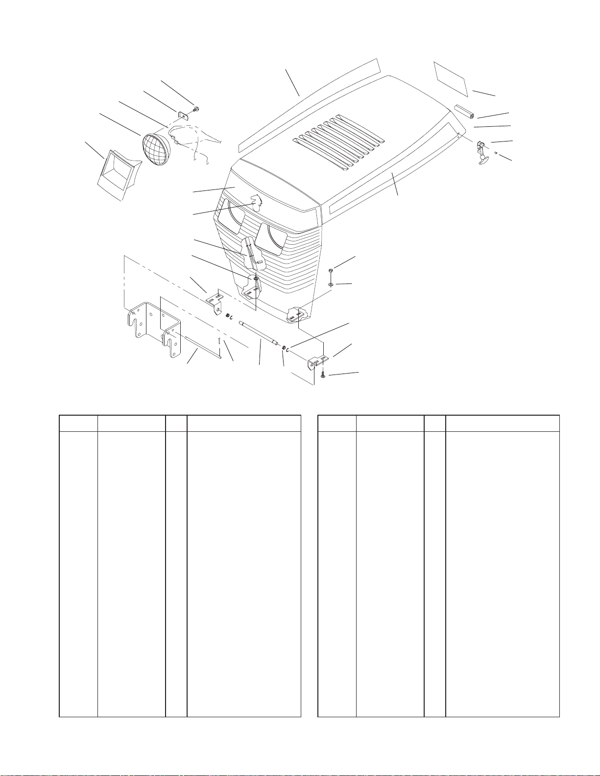
Hood Assembly
DescriptionPart No. Qty.Ref. No. DescriptionPart No. Qty.Ref. No.
1 109495 1 Bezel–LH Headlight
2 109494 1 Bezel–RH Headlight
3 102881 2 Headlamp
4 114052 1 Wire Harness
5 109459 2 Clamp–Headlight
6 9266714 2 Screw–HWHTF
7 111757 1 Edging
9 117432 4 Poprivet
10 117344 2 Handle–Latch
11 3296–42 4 Nut–Lock
12 3256–22 3 Washer–Flat
13 116747 1 Bracket–Grill LH
14 3229–25 4 Screw–CARR
15 101850 1 Rod–Hood Stop
16 3272–1 2 Pin–Cotter
17 5979 2 Bushing–Nyliner
18 105797 2 Ring–Retaining
19 116745 1 Rod–Grill Pivot
20 116746 1 Bracket–Grill RH
21 3254–2 1 Washer–Lock
22 3290–378 1 Tie–Cable
23 94–3736 1 Plate–Logo
24 92–9826 1 Decal–Front Hood
25 92–9825 1 Decal–Hood RH
26 93–7336 1 Decal–Danger
27
11
12
17
13
18191615
14
Sheet No.: 2
27 92–9824 1 Decal–Hood LH
28 112358 1 ASM–Hood & Grill
1
3319–162
5 6 8 9
7
10
11
23
34
9
17
33
RH 31
LH 32
4
3
2
1
19
20
22
35
24
25
26
27
287303
23
12
13
14
15
16
17
18
21
21:1
Sheet No.: 3
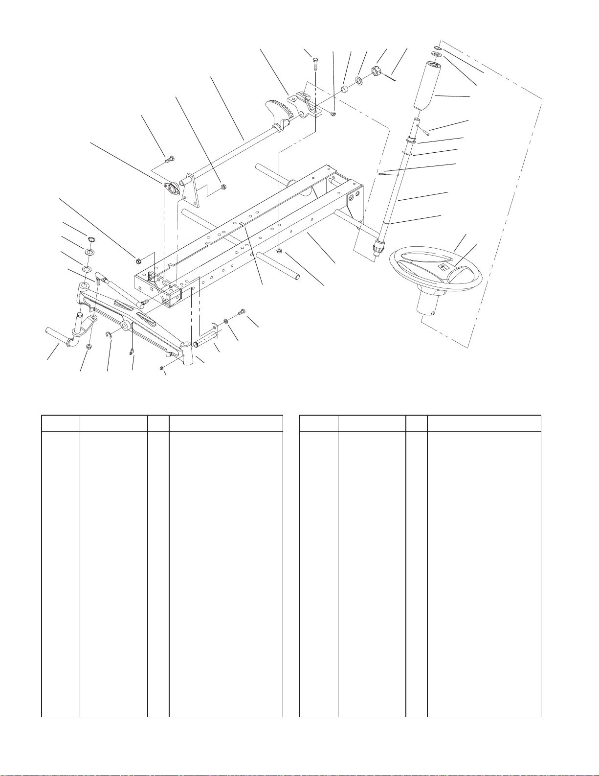
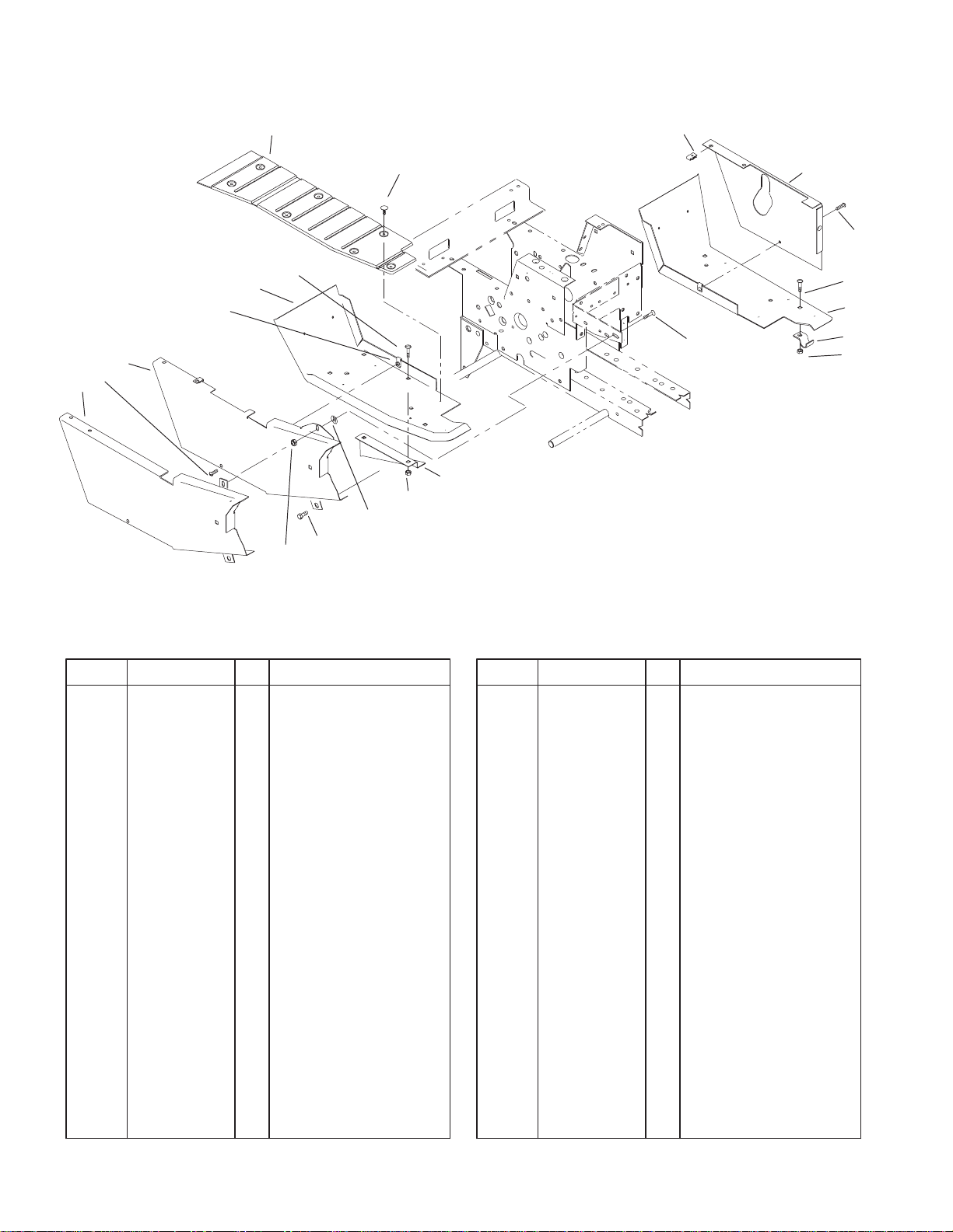
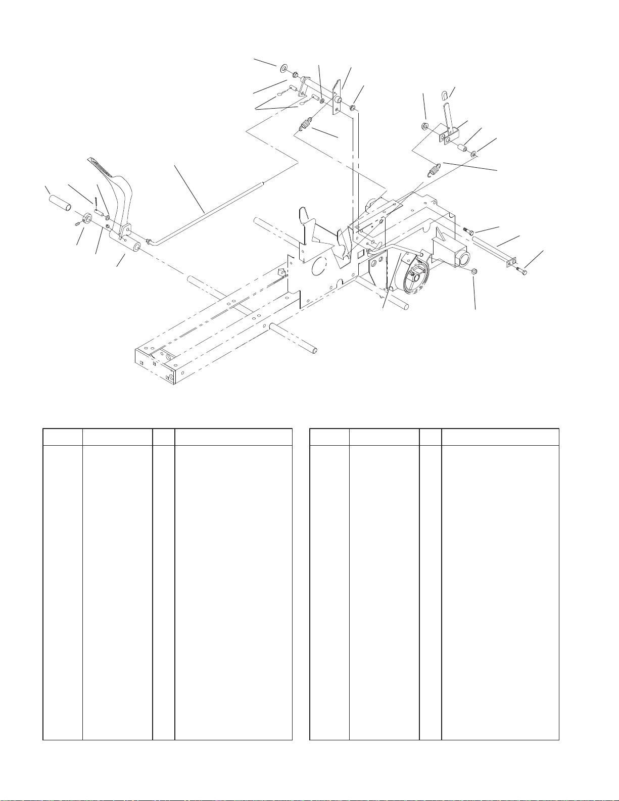
Frame Axle and Steering System
DescriptionPart No. Qty.Ref. No. DescriptionPart No. Qty.Ref. No.
1 6472 1 Bearing–Flanged
2 323–6 2 Screw–HH
3 3296–6 4 Nut–Lock
4 78–2880–01 1 Shaft–Steering
5 88–2710–01 1 Support–Lower
Steering
6 323–8 2 Screw–HH
7 302–11 2 Fitting–Grease
8 6397 1 Bearing–Bronze
9 1278 3 Washer–Shim
10 32136–5 1 Nut–Slotted
11 3272–19 1 Pin–Cotter
12 7896 1 Washer–Bowed
13 109262 2 Washer
14 113443 1 Tube–Steering Shaft
15 32121–111 1 Pin–Spiral
16 109189 1 Bearing–Flange
17 5210 14 Washer–Shim
18 3272–21 1 Pin–Cotter
19 92–4987 1 Shaft–Steering
20 237–69 1 O–Ring
21 94–3519 1 Wheel–Steering
21:1 88–3870 1 Cover–Steering Wheel
22 94–6673–01 1 Frame
23 3296–39 4 Nut–Lock
24 322–1 1 Screw–HH
25 3253–4 1 Washer–Lock
26 6216 1 Pin–Pivot
27 5638–01 1 Axle–Front
28 302–5 2 Fitting–Grease
30 5618 1 Ring–Retaining
31 113382–01 1 Spindle–RH
32 113381–01 1 Spindle–LH
33 78–2900 2 ASM–Rod
34 32120–93 2 Snap Ring
2
8 11
9
10
8
37
3319–162
33
28
34 3635
2
1
3
4
1
32
31
8
27
26
65
7
8
16
38
17
18
19 20
12
13
14
15
21
25
8
24 23
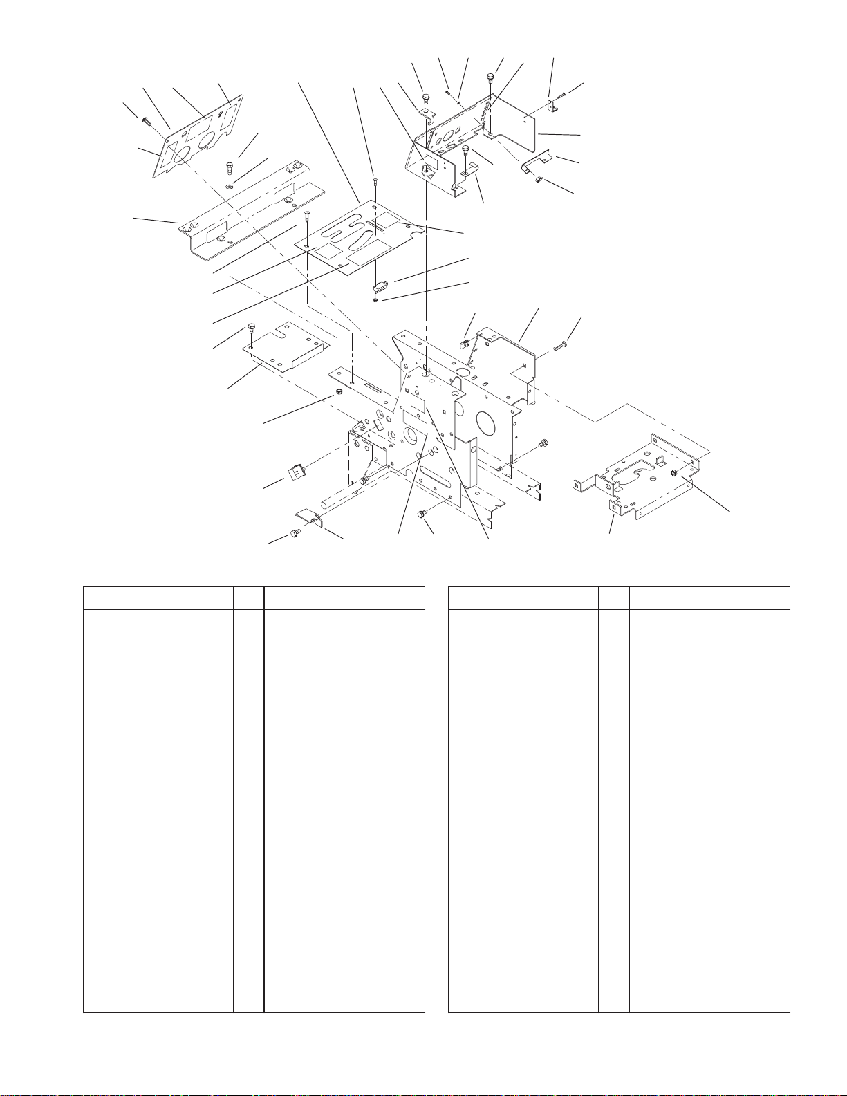
Hoodstand, Console
DescriptionPart No. Qty.Ref. No. DescriptionPart No. Qty.Ref. No.
1 9108372 6 Screw–Phcr
2 94–1809–03 1 Plate–Hoodstand
3 322–5 2 Screw–HH
4 3256–23 2 Washer–Flat
5 111386–03 1 Plate–Shift
6 9109484 2 Screw–Phcr
7 112415 1 Stop–PTO
8 9266944 11 Screw–HH
9 9107622 2 Screw–Phcr
10 9201504 2 Washer–Lock
11 117343 2 Latch–Hood
12 117432 4 Poprivet
13 111271–03 1 Console
14 112506 1 Bracket
15 9159604 2 Nut
16 111392 1 Retainer
17 111332 1 Switch–Interlock
18 9157324 2 Nut–Lock
19 107069 4 Nut–Retainer
20 92–1525–03 1 Hoodstand
21 117371 4 Screw–CARR
22 9151126 4 Nut
23 78–3010–03 1 Bracket–Battery
Support
24 88–2170–03 1 Bracket–Belt
25 103480 1 Switch–Interlock
30 29
8
26 3296–29 2 Nut–Lock
27 106250–03 1 Cover–Dust
28 107951–03 1 Bracket–Fender Front
29 114621 1 Decal–Noise
30 92–9831 2 Decal– 416–8 Speed
31 92–8946 1 Decal–Danger
31 93–7314 1 Decal–Danger
32 93–7845 1 Decal–Pattern
33 93–7847 1 Decal–Clutch
34 94–6658 1 Decal–Plate
35 93–7848 1 Decal–Lift
36 93–7846 1 Decal–System
37 93–9350 1 Decal–Dash
38 93–9352 1 Decal–Brake
22
Sheet No.: 6
3
3319–162
Any part identified in this illustration but not included in the parts list is not used on this model.
RH 1
LH 2
5
19
3
8
17
5
12
16
7
13
11
14
15
11
6
7
8
9
10
11
Sheet No.: 9
Footrest & Hoodstand Side Covers
DescriptionPart No. Qty.Ref. No. DescriptionPart No. Qty.Ref. No.
1 94–3710 1 Mat–Foot RH
2 94–3712 1 Mat–Foot LH
3 3290–479 16 Fastener–Panel
5 107069 6 Nut–Retainer
6 113935–01 1 Cover–Side LH
7 9108372 2 Screw–Phcr
8 116000 6 Screw–CARR
9 94–3522–01 1 Footrest LH
10 7456 4 Clamp
11 3296–29 7 Nut–Lock
12 3230–1 1 Bolt–CARR
13 106352–01 1 Guard–Lower Belt
14 108457 1 Nut–Push On
15 9266944 1 Screw–HH
16 94–3725–01 1 Belt–Guard
17 94–3521–01 1 Footrest RH
4
3319–162
7
6
5
8
9
4
3
2
1
16 20 19
17
15
14
22
11:1
15:3
15:1
15:2
18
11:2
12:1
14:2
14:1
13
12:2
12:3
10
11
12
13:2
13:1
21
13:2
Sheet No.: 10
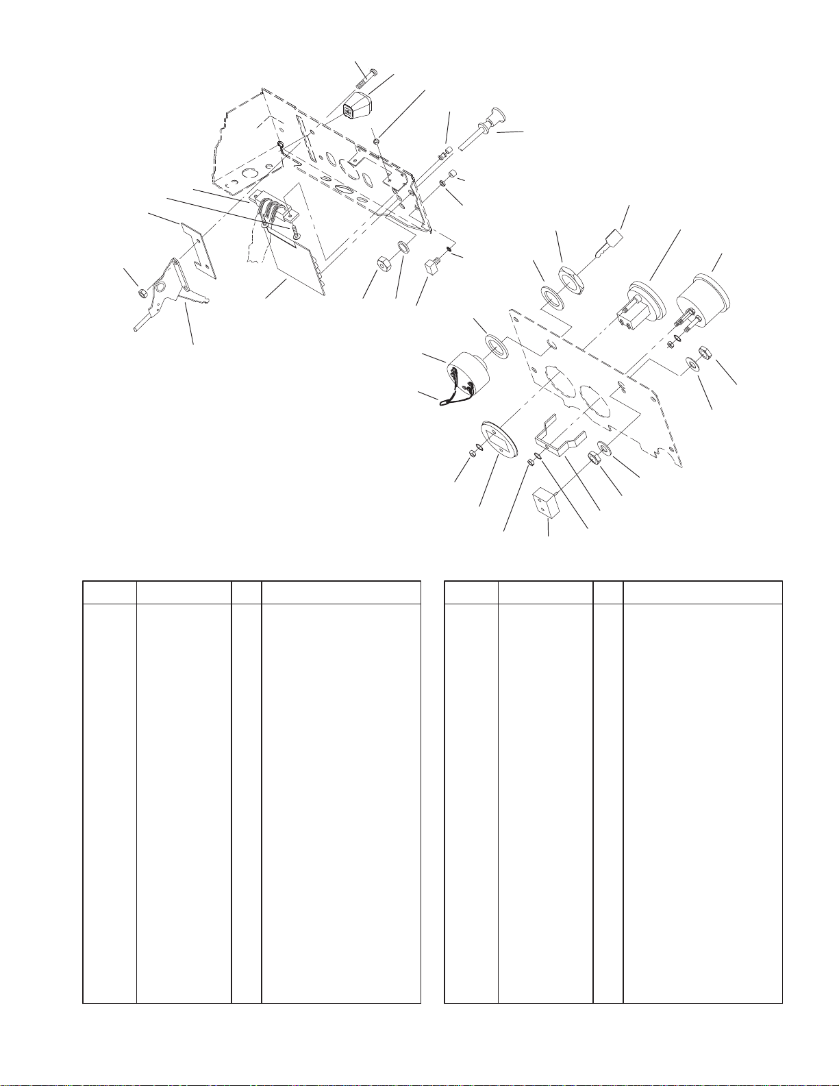
Gauges, Warning Lights & Controls
DescriptionPart No. Qty.Ref. No. DescriptionPart No. Qty.Ref. No.
1 9157404 2 Nut
2 120590–03 1 Stop–Throttle
3 9107562 2 Screw–Phcr
4 117377 1 Harness–P C Board
5 9157324 2 Nut–Lock
6 66–0120 1 Knob
7 9107922 2 Screw–Phcr
8 111343 5 Lens & Bushing ASM
9 114951 1 Control–Choke
10 62–7770 2 Key–Ignition
11 94–3723 1 Hourmeter
11:1 32149–9 2 Nut/Washer–Lock
11:2 94–1849 1 Cup–Retainer
12 79–0060 1 Voltmeter
12:1 3217–27 1 Nut–HH
12:2 3255–25 1 Washer–Lock
12:3 78–0080 1 Bracket–Mounting
13 102138 1 Switch–Light
13: 102950 1 Washer–Tab
13: 113179 1 Nut–Hex
14 111216 1 Switch–Ignition
14:1 101884 1 Nut–Hex
14:2 9201604 1 Washer–Lock
15 116796 1 Switch–Button
15:1 111359 1 Nut–Hex
15:2 111767 1 Washer–Lock
15:3 117217 1 Button–Switch
16 114825 1 Board–Pc
17 115392 1 Control–Throttle
18 9202624 1 Washer–Flat
19 3256–37 1 Washer–Flat
20 109530 1 Nut–Hex Palnut
21 9202594 1 Washer
22 79–3600 1 Wire Harness (Ref.)
5
3319–162
33
32
37
36
35
34
25
38
39
24
4
5
23
22
10
21
10
6
7
3
2
8
9
20
27
19
11
12
13
14
15
16
17
21 3
4
4
3938
32
31
5 4 30 29 28
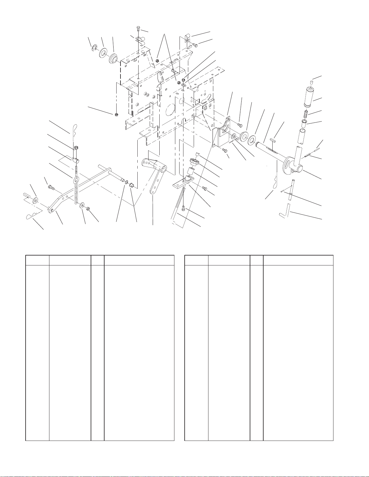
Manual Lift System
DescriptionPart No. Qty.Ref. No. DescriptionPart No. Qty.Ref. No.
1 32151–91 1 Ring–Retaining
2 3256–62 2 Washer–Flat
3 106269 2 Bearing–Flange
4 3296–29 6 Nut–Lock
5 3256–23 3 Washer–Flat
6 106411–03 1 ASM–Lift Hgt Cont
Bkt
7 9266944 1 Screw–HH
8 108565 1 Shaft–Lift Lever
9 1121 1 Key
10 105316 2 Cap–Rod
11 92–6710 1 Grip–Handle
12 3624 1 Spring–Compression
13 8130 1 Retainer–Spring
14 32121–103 1 Pin–Spring
15 32121–25 1 Pin–Roll
16 108563–03 1 ASM–Lift Lever
17 933148 1 Pin–Spirol
18 106257 1 Rod–Latch
19 9335074 2 Cotter–Hairpin
20 3256–5 1 Washer–Flat
21 9266964 2 Screw–HH
22 5280 1 Knob–Height Control
23 106258–03 1 Sleeve
24 322–5 3 Screw–HH
25 106345–03 1 Casting–Lift Lever
24
26
Sheet No.: 13
26 110653 1 Rod–Height Control
27 3272–10 1 Pin–Cotter
28 78–1550 1 Lever–Lift
29 6229 1 Bearing
30 32120–47 1 Ring–Retaining
31 113445–01 1 Bar–Lift
32 9335054 2 Hairpin
33 3256–25 1 Washer–Flat
34 322–6 1 Screw–HH
35 106522 1 Chain–Lift
36 6739 1 Trunnion
37 3296–39 1 Nut–Lock
38 8830 4 Retainer–”J”
39 322–2 2 Screw–HH
18
6
31
2
3
4
1
33
32
5
6
7
8
3319–162
30
29
28
27
26
25
24
416 FRAME/ENGINE PLATE
COMBINATION SHOWN
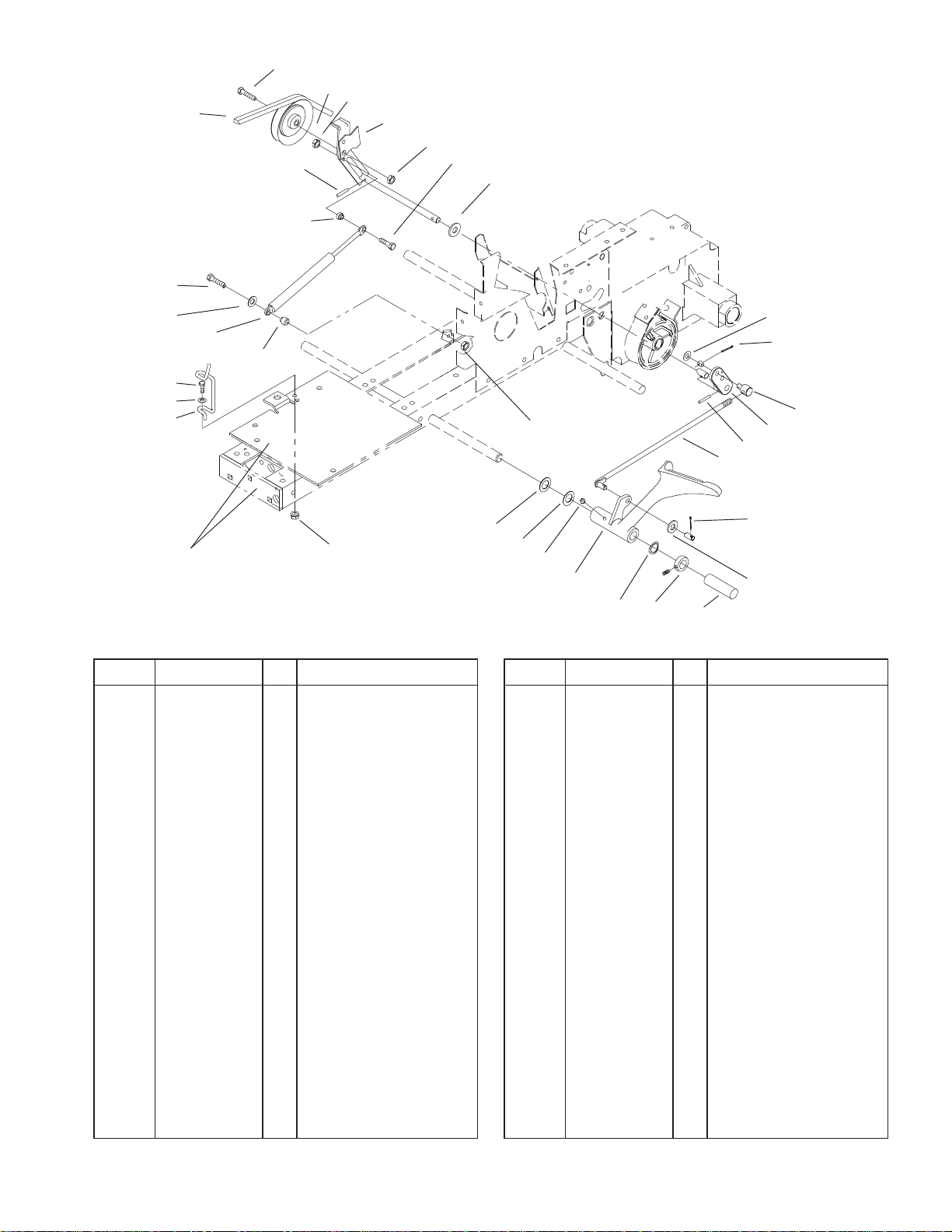
DescriptionPart No. Qty.Ref. No. DescriptionPart No. Qty.Ref. No.
1 93–9809 1 V–Belt
2 106193 1 Screw–Spec HH
3 7451 1 Pulley–V
4 3296–42 2 Nut–Lock
5 78–2970–01 1 ASM–Clutch Idler Arm
6 32146–2 1 Nut–Lock
7 321–31 1 Screw–HH
8 3765 1 Washer–Shim
9 3272–6 1 Pin–Cotter
10 3256–24 1 Washer–Flat
11 101161 1 Trunion
12 105896–01 1 Arm–Clutch Rod
13 933190 1 Pin
14 103347 1 Rod–Clutch
15 3272–10 1 Pin–Cotter
16 920248 1 Washer–Nylon
17 94–6683 1 Sleeve–Protective
18 111383 1 Collar w/Set Screw
19 7896 1 Washer–Bowed
20 94–3703–01 1 Pedal–Clutch
21 302–5 1 Fitting–Grease
22 1278 1 Washer–Shim
23 9202254 1 Washer–Flat
24 3296–29 1 Nut–Lock
25 120320–03 1 Guide–Belt Bottom
26 3256–3 1 Washer–Flat
23
22
Clutch
10
9
11
12
15
16
Sheet No.: 18
21
4
13
14
20
19
18
17
27 322–6 1 Screw–HH
28 78–3250 1 Spacer–Shoulder
29 78–3240 1 Absorber–Gas Spring
30 3256–22 1 Washer–Flat
31 321–9 1 Screw–HH
32 78–3260 1 Spacer–Shoulder
33 933267 1 Pin
7
3319–162
21
22
20
4
19
18
23
2
1
3
4
5
1
6
13
7
8
9
10
11
12
14
16
17
15
DescriptionPart No. Qty.Ref. No. DescriptionPart No. Qty.Ref. No.
1 7879 2 Bushing
2 3256–26 1 Washer–Flat
3 9335054 2 Hairpin
4 920248 2 Washer–Nylon
5 103543–03 1 Bellcrank–Brake
6 103628 1 Spring–Extension
7 32128–19 1 Nut–Lock
8 6820 1 Grip
9 106451–03 1 Lever–Parking Brake
10 102025 1 Spacer
11 3256–24 1 Washer–Flat
12 107677 1 Spring–Extension
13 105900 1 Rod–Brake
14 323–9 1 Screw–HH
15 3296–39 1 Nut–Lock
16 106417 1 Rod–Pivot
17 9266944 1 Screw–HH
18 94–3706–01 1 Pedal–Brake
19 302–5 1 Fitting–Grease
20 111383 1 Collar w/Set Screw
21 94–6683 1 Sleeve–Protective
22 3272–10 1 Pin–Cotter
23 92–6849 1 Rod–Brake
Sheet No.: 19
Brake
8
Any part identified in this illustration but not included in the parts list is not used on this model.
21 22:1
26
19
9
20
22
23
24
3319–162
11
29
12
8
4
7
6
5
4
3
2
1
10
17
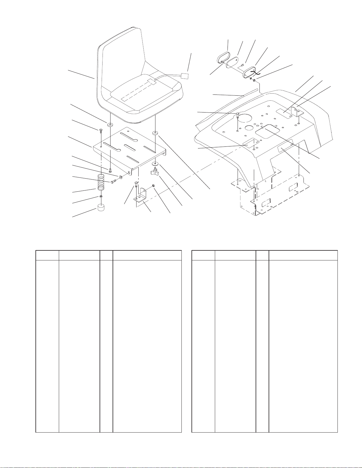
Fender, Seat & Tail Lights
DescriptionPart No. Qty.Ref. No. DescriptionPart No. Qty.Ref. No.
1 701178 2 Cap–Protector
2 3296–58 2 Nut–Flange
3 92–7054 2 Spring–Compression
4 322–4 4 Screw–HH
5 105503 2 Bushing
6 92–6986 2 Bolt–Shoulder
7 92–6972–03 1 Support–Seat
8 92–6750 2 Spacer–Nylon
9 92–6511 1 Seat
10 9266944 8 Screw–HH
11 94–3722–01 1 Fender
12 79–0970–03 1 Bracket–Pivot LH
13 109989 2 Spacer
14 94–2869 2 Washer–Flat
15 700806 2 Knob
16 3296–29 2 Nut–Lock
17 79–0950–03 1 Bracket–Pivot RH
19 38–1420 1 Switch–Seat
20 3250–31 4 Screw–Phcr
22 105202 2 Base–Light
23 3254–1 4 Washer–Lock
24 3296–27 4 Nut–Lock
25 3023 2 Clip
26 112564 2 Lens–Light
28 92–9827 1 Decal–Fender
28
10
27
25
30
13
14
15
16
Sheet No.: 20
9
3319–162
2727
26
25
24
3
5
4
3
2
1
23
7
10
11
9
8
12
13
14
15
16
28
17
25
21
20
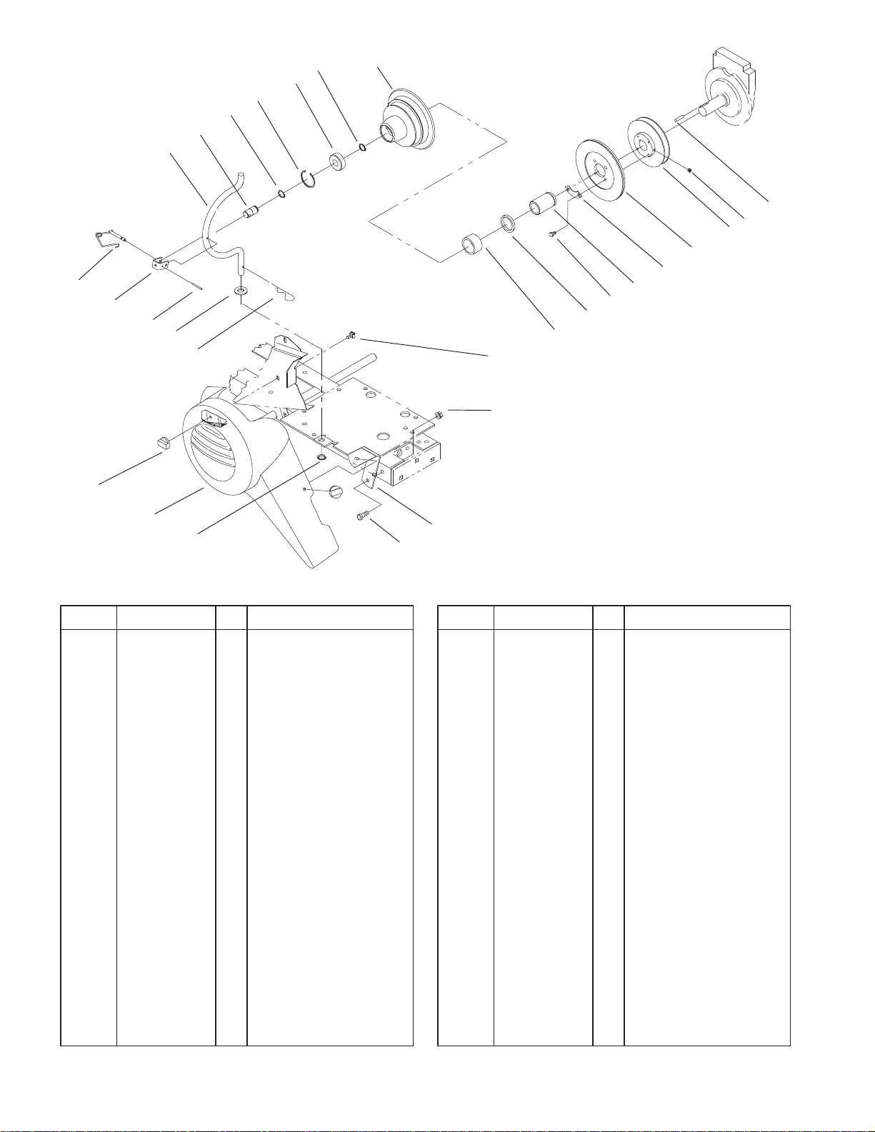
PTO Clutch And Cover
DescriptionPart No. Qty.Ref. No. DescriptionPart No. Qty.Ref. No.
1 113108 1 Rod–PTO Housing
2 102872 1 Shaft–PTO
3 32120–72 2 Ring–Retaining
4 32120–62 1 Ring–Retaining
5 109842 1 Bearing–Ball
7 103478–01 1 Housing–Clutch
8 94–6650 1 ASM–Plate
9 7466 1 Pulley–Engine
10 105453 1 Key–Sq
11 3246–2 2 Screw–HSH Set
12 6659 2 Retainer
13 6658 1 Race–Bearing
14 9080026 4 Screw–Lock
15 6663 1 Seal–Oil
16 6662 1 Bearing–Needle
17 32128–40 1 Nut–Lock
18 94–3726–01 1 Bracket
19 323–6 1 Screw–HH
20 106695 1 Ring–Push On
21 94–3704 1 Belt Cover–PTO
22 94–3735 2 Nut–Wing
23 9335064 1 Hairpin
24 3256–27 1 Washer–Flat
25 933274 1 Pin–Spirol
26 113107 1 Clevis
19
18
Sheet No.: 22
27 111314 1 Lock Pin ASM
28 94–3729 1 Retainer–Bolt
10
Any part identified in this illustration but not included in the parts list is not used on this model.
3319–162
7
6
5
4
1
3
2
23
500 SERIES
8 9 10 11
22
20
21
19
12 13
17
18
16
15
24
14
25
27
26
400 SERIES
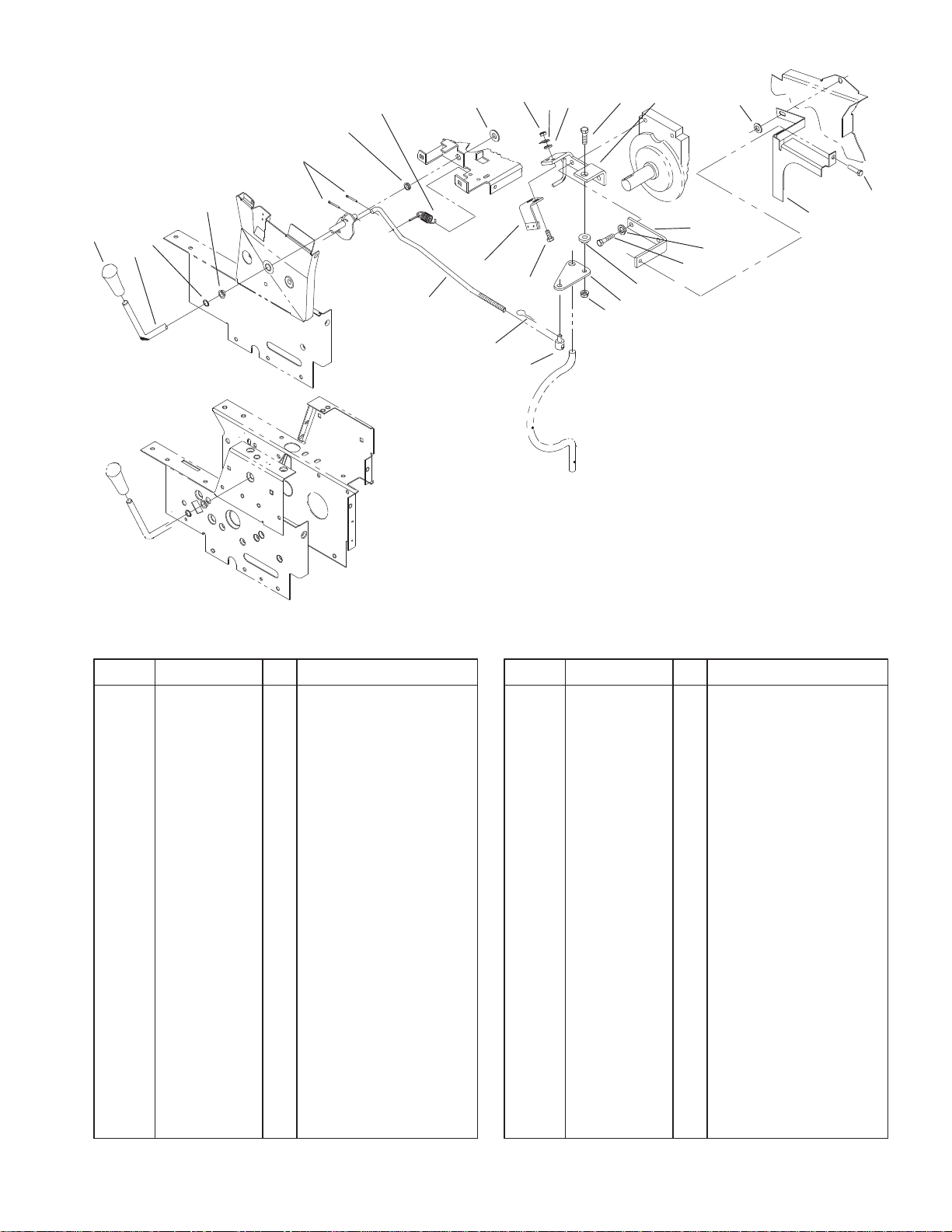
PTO Clutch System
DescriptionPart No. Qty.Ref. No. DescriptionPart No. Qty.Ref. No.
1 94–3727 1 Knob
2 94–3701 1 Rod–PTO Control
3 32151–11 1 Ring–Grip
4 5666 1 Bushing–Nyliner
5 3272–10 3 Pin–Cotter
6 5983 1 Bushing
7 103125 1 Spring–Extension
8 3765 1 Washer–Shim
9 3218–1 2 Nut–Jam
10 3253–3 2 Washer–Lock
11 3256–22 2 Washer–Flat
13 113853–03 1 Bracket–PTO
14 3253–21 2 Washer–Lock
15 323–7 2 Screw–HH
16 104859 1 Spacer–Link
17 110669 1 Plate–PTO
18 3296–59 1 Nut–Lock
19 110656 1 Trunnion
20 3229–25 2 Screw–CARR
21 9335054 1 Hairpin
22 94–6652 1 ASM–Brake
23 111052 1 Rod–PTO Clutch
24 94–1584–03 2 Bar–Support
25 3256–23 1 Washer–Flat
26 94–1587–03 1 Guard
27 9266944 1 Screw–HH
Sheet No.: 24
11
3319–162
28
1
2
3
4
24
27
26
25
23
22
21
20
19
18
5
6
7
30
8
9
10
11
12
13
14
29
17
17
Sheet No.: 26
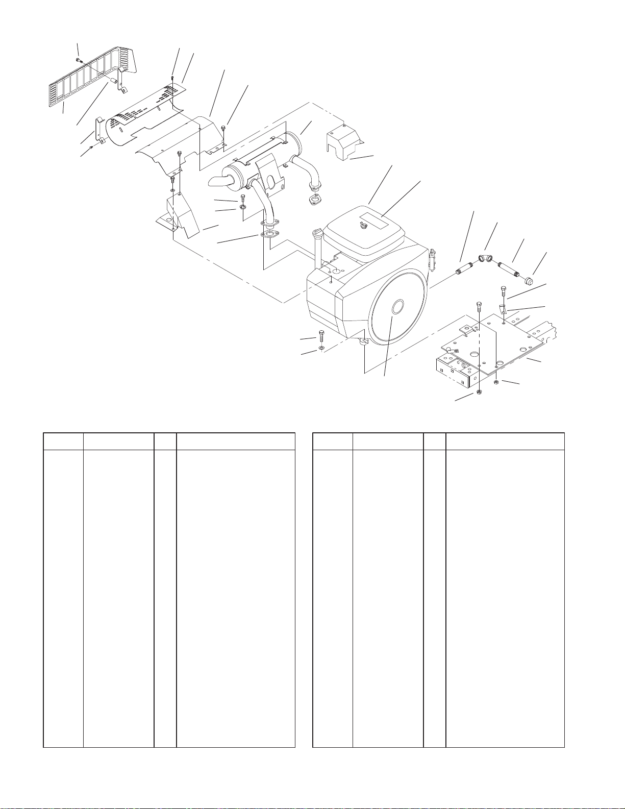
Engine Assembly
DescriptionPart No. Qty.Ref. No. DescriptionPart No. Qty.Ref. No.
1 114888 2 Screw
2 94–6664 1 Shield–Heat
3 94–1803–03 1 Baffle–Deflector
4 49–2040 3 Screw–HH
5 116471 1 Muffler
6 114216–03 1 Cover–Exhaust Rear
7 94–1810 1 Engine–Onan
8 114636 1 Nipple
9 114764 1 Elbow–90
10 114763 1 Nipple
11 288–4 1 Cap–Pipe
12 323–6 4 Screw–HH
13 8830 2 Retainer–”J”
14 116609–03 1 Plate–Engine
17 3296–39 8 Nut–Lock
18 3256–24 4 Washer–Flat
19 323–8 4 Screw–HH
20 114215–03 1 Cover–Exhaust Front
21 57–9210 2 Gasket–Manifold
22 3253–4 4 Washer–Lock
23 322–3 4 Screw–HH
24 94–9700–03 1 Shield–Heat
25 32144–28 4 Screw–Phcr
26 93–9287–03 2 Bar–Guard
27 94–9701 4 Spacer
28 32144–110 4 Screw–HWHTF
29 118530 1 Name Plate–Toro
Logo
30 118540 1 Decal–Power Plus 16
12

23
3319–162
3
2
1
22
21
20
19
18
17
16
15
14
Transmission Assembly
DescriptionPart No. Qty.Ref. No. DescriptionPart No. Qty.Ref. No.
1 83–2710 1 Knob
2 95–5142 1 ASM–Rod
3 108758 1 Knob
4 101847–03 1 Dipstick
5 102703 1 Trans Nipple
6 94–6671 1 ASM–8 Spd
7 321–3 2 Screw–HH
8 3253–3 2 Washer–Lock
9 9598 1 Plate–Stop
10 9593 1 Band–Brake
11 106719 1 Drum–Brake
12 2844 1 Washer–Flat
13 110234 1 Screw
14 323–5 4 Screw–HH
15 3253–21 4 Washer–Lock
16 3217–5 1 Nut–Hex
17 1239 1 Set Screw
18 937221 1 Key–Woodruff
19 106165 1 Pulley–Transmission
20 3242–2 1 Screw Set–SH
21 3577 1 Dust Cover
22 933184 1 Pin–Spirol
23 110727 1 Rod–Shift
24 94–1834 1 Decal–Unidrive
25 937108 2 Key–Woodruff
26 3243–5 4 Screw–Set
4
5
6
7
8
9
10
11 12 13
24
25
27 3218–3 4 Nut–HJ
28 105763–03 2 Hub–Wheel
26
27
28
Sheet No.: 27
13
3319–162
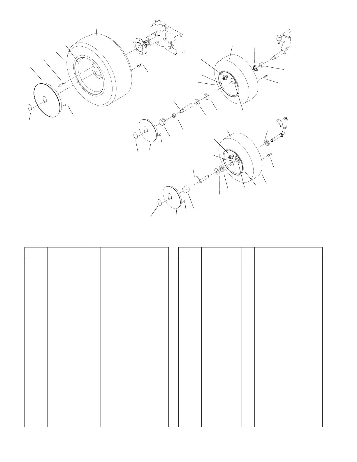
Any part identified in this illustration but not included in the parts list is not used on this model.
3:2
3:1
3
2
17
1
16
1:1
Rear W / T 312, 314, 416 & 520
Front W / T 314, 416, & 520
Front W / T 312-8
16
16
18
3:3
4
4:1
10:4
10:6
10:1
10
7
9
8
10:4
6
5
4
18
10:6
15
7
14
13
12
4:1
10:2
10:5
10:1
11
10:3
14
10:3
1010:2
Sheet No.: 29
Wheel Assemblies
DescriptionPart No. Qty.Ref. No. DescriptionPart No. Qty.Ref. No.
2 83–2720 10 Bolt–Lug
3 2 ASM–Wheel & Tire
3:1 111516 2 Wheel
3:2 116744 2 Tire
3:3 5108 2 Valve–Tire Tubeless
7 3272–17 2 Pin–Cotter
10 93–9800 2 ASM–Wheel & Tire
10:1 93–9801 2 ASM–Wheel w/Zerk
10:2 110513 4 Bearing–Wheel
10:3 5108 2 Valve–Tire Tubeless
10:4 117127 2 Tire
10:6 109500 2 Fitting–Grease
12 111951 2 Cap–Hub
13 111952 2 Washer
14 1278 4 Washer–Shim
15 5210 2 Washer–Shim
14
3319–162
20
18
25
24
23
27
22
26
5 6 7
1
28
17
18 1516
29
1
12
14
3
Sheet No.: 30
14
2
20
18
29
4
3
19
8
9
10
11
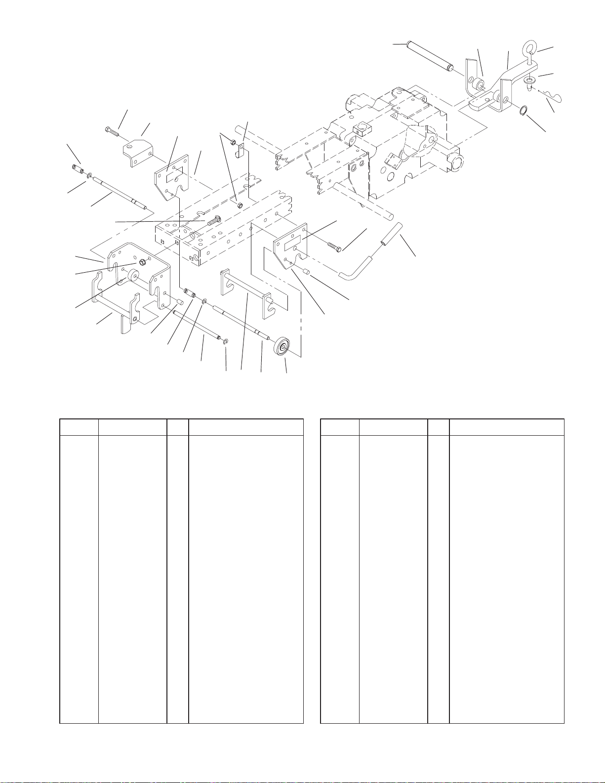
Hitch Assembly
DescriptionPart No. Qty.Ref. No. DescriptionPart No. Qty.Ref. No.
1 323–44 6 Screw–HH
3 102644–01 2 Plate–Hitch
4 108881 6 Nut–Hex
5 105269 1 Pin–Drawbar Hitch
6 9791204 2 Spacer
7 1644–01 1 Hitch ASM
8 106634 1 Pin–Tool
9 3256–26 1 Washer–Flat
10 9335054 1 Hairpin
11 5618 2 Ring–Retaining
12 9038 1 Grip
14 105316 2 Cap–Rod
15 101017 1 Lock–Hitch
16 83–6520 1 Rod–Lock
17 117930 1 Latch ASM–Mid
18 105797 8 Ring–Retaining
19 101750 1 Rod–Latch Pivot
20 8616 2 Spring
22 93–1613 1 Latch–Front
23 101707 1 Lock–Attachment
24 3296–39 3 Nut–Lock
25 101711–01 1 Plate–Front Hitch
26 3231–25 3 Screw–CARR
27 101751 1 Rod–Lock
28 8830 1 Retainer–”J”
29 92–8747 2 Decal–Attach A Matic
15
 Loading...