

Page 1

FORM NO. 3322–108
CLASSIC GARDEN TRACTOR
300 SERIES
S/N 9900001 & Up
Loose
Note: Use the chart below to identify parts for assembly.
DESCRIPTION QTY. USE
Hitch Pin
Hairpin Cotter – 1-7/8”
Flat W
Bolt – 1/4–20 x 3/4”
Hex Nut – 1/4–20
Hairpin Cotter – 1-7/8”
Flat W
Operator’
Parts
asher – 1/2 x 1”
asher – 1/2 x 1”
s Manual
1
1
1
2
2
1
1
1
Installing the hitch pin
Attaching the battery cables
Attaching accessory to lift bar
Read before operating tractor
SET UP
INSTRUCTIONS
Set Up Instructions
Riding Mower Safety V
Printed in USA
ideo
1
1
The T
oro Company – 1998
All Rights Reserved
Read before setting up tractor
V
iew before operating tractor
Page 2
Set-Up Instructions
Checking
Check the front and rear tire pressure. The correct
front and rear tire pressure is 12 psi (83 kPa).
Activating
POTENTIAL
the T
ire Pressure
the Battery
HAZARD
• Battery electrolyte contains sulfuric acid
which is a deadly poison and it causes
severe burns.
WHAT CAN HAPPEN
• If you carelessly drink electrolyte you could
die or if it gets onto your skin you will be
burned.
HOW TO AV
OID THE HAZARD
• Do not drink electrolyte and avoid contact
with skin, eyes or clothing. Wear safety
glasses to shield your eyes and rubber
gloves to protect your hands.
• Fill the battery where clean water is always
available for flushing the skin.
• Follow all instructions and comply with all
safety messages on the electrolyte container.
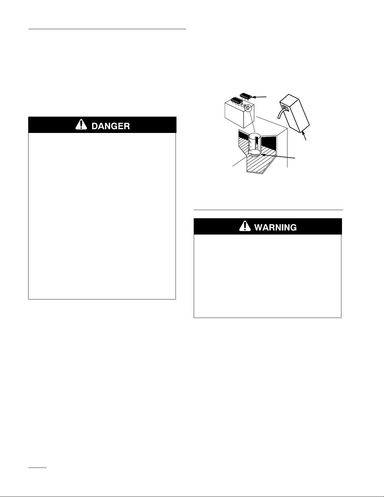
1. Remove the battery from the tractor.
2. Remove the filler caps from the battery. Slowly
pour electrolyte into each cell until the
electrolyte level is up to the lower part of the
tube (Fig. 1). Use an electrolyte with a specific
gravity of 1.265.
1
2
3
1262
Figure 1
1. Filler
2. Electrolyte
Caps
POTENTIAL
HAZARD
• Charging battery pr
WHAT CAN HAPPEN
Lower part of the tube
3.
oduces gasses.
• Battery gasses can explode.
HOW TO AV
OID THE HAZARD
• Keep cigarettes, sparks and flames away
from battery.
Note: Never fill the battery with electrolyte
with the battery installed in the tractor.
Electrolyte could be spilled on other
parts and cause corrosion.
2
3. Leave the filler caps off and connect a 3–4 amp
battery charger to the battery posts (Fig. 2).
Charge the battery at a rate of 4 amperes or less
for 4 hours (12 volts).
Page 3

Set-Up Instructions
4. When the battery is fully charged, unplug the
charger from the electrical outlet, then
disconnect the charger leads from the battery
posts (Fig. 2).
4
2
3
1
Figure 2
1. Positive
2.
Battery Post
Negative Battery Post
3.
Red (+) Charger Lead
4.
Black (–) Charger Lead
1254
Installing
the Drawbar Hitch
Pin
Insert the drawbar hitch pin into the drawbar hitch
and secure it with a
hairpin cotter (Fig. 3).
1. Drawbar
2.
Drawbar Hitch
Hitch Pin
1/2 x 1”
2
4
Figure 3
flat washer and 1-7/8”
1
3
3.
Flat W
asher 1/2 x 1”
4.
Hairpin Cotter 1-7/8”
m–3396
5. Slowly pour electrolyte into each cell until the
level is once again up to the “UPPER” line on
the battery case (Fig. 1), then install the filler
caps.
6. Install the battery in the tractor and connect the
battery cables. (Refer to the Operator’
s Manual –
Installing the Battery.)
Note: Do not run the tractor with the battery
disconnected, electrical damage may
occur.
Attaching
the W
asher and
Hairpin Cotter onto the Lift Bar
Install a
onto the lift bar (Fig 4).
1. Lift
2.
2
3
Bar
Flat W
1/2 x 1”
asher 1/2 x 1”
flat washer and 1-7/8” hairpin cotter
1
Figure 4
3.
Hairpin Cotter1-7/8”
m–2504
3
Page 4

Set-Up Instructions
Checking
the W
iring and
Fasteners
• Inspect the tractor for any loose electrical
connections and secure as required. Check the
wire routing to make sure no moving parts
interfere with the wires to cause a short.
• Check all fasteners to make sure they are tight.
Test
1. Check the oil level in the crankcase. Refer to the
2. Check the oil level in the transaxle. Refer to the
3. Check to make sure all lubrication points have
Driving the T
Operator’s Manual for oil type, viscosity and
crankcase capacity
Note: When checking the oil level, slide the
dipstick all the way into the filler tube.
Operator’s Manual for oil type, viscosity and
capacity.
been greased as shown in the Maintenance
section of the Operator’s Manual. These points
include the front axle pivot and spindles, foot
pedal(s) and steering gear.
ractor
.
5. As applicable, check and test the operation of the
following:
• Engine, choke and throttle controls
• Gauges
• Headlights (and taillights 314 only)
• Indicator lights (314 only)
• PTO clutch and brake
• Lift system
• Service and parking brakes
• T
ransmission controls
• Steering
• Tractor operation in forward and reverse
6. Test the operation of the safety interlock system.
The engine should not crank if:
• You are out of the seat
• The PTO lever is in the “engaged” position
• The gear shift lever is in the “engaged”
position
4. Fill the tank with unleaded regular gasoline with
an octane rating of at least 85. Open the fuel
shutoff valve and check the fuel hose and fittings
for leaks.
4
 Loading...