


FormNo.3447-510RevA
ZMaster
®
Professional6000
SeriesRidingMower
With60inor72inTURBOFORCE
DischargeMower
ModelNo.72980—SerialNo.400000000andUp
ModelNo.72982—SerialNo.400000000andUp
®
Side
Registeratwww.T oro.com.
OriginalInstructions(EN)
*3447-510*

ItisaviolationofCaliforniaPublicResourceCode
Section4442or4443touseoroperatetheengineon
anyforest-covered,brush-covered,orgrass-covered
landunlesstheengineisequippedwithaspark
arrester,asdenedinSection4442,maintainedin
effectiveworkingorderortheengineisconstructed,
equipped,andmaintainedforthepreventionofre.
Theenclosedengineowner'smanualissupplied
forinformationregardingtheUSEnvironmental
ProtectionAgency(EPA)andtheCaliforniaEmission
ControlRegulationofemissionsystems,maintenance,
andwarranty.Replacementsmaybeorderedthrough
theenginemanufacturer.
GrossorNetT orque:Thegrossornettorque
ofthisenginewaslaboratoryratedbytheengine
manufacturerinaccordancewiththeSocietyof
AutomotiveEngineers(SAE)J1940orJ2723.As
conguredtomeetsafety,emission,andoperating
requirements,theactualenginetorqueonthisclass
ofmowerwillbesignicantlylower.Pleasereferto
theenginemanufacturer’sinformationincludedwith
themachine.
Introduction
Thisrotary-blade,ridinglawnmowerisintendedtobe
usedbyprofessional,hiredoperators.Itisdesigned
primarilyforcuttinggrassonwell-maintainedlawns
onresidentialorcommercialproperties.Usingthis
productforpurposesotherthanitsintendedusecould
provedangeroustoyouandbystanders.
Readthisinformationcarefullytolearnhowtooperate
andmaintainyourproductproperlyandtoavoid
injuryandproductdamage.Y ouareresponsiblefor
operatingtheproductproperlyandsafely .
Visitwww.Toro.comforproductsafetyandoperation
trainingmaterials,accessoryinformation,helpnding
adealer,ortoregisteryourproduct.
Wheneveryouneedservice,genuineToroparts,or
additionalinformation,contactanAuthorizedService
DealerorToroCustomerServiceandhavethemodel
andserialnumbersofyourproductready.Figure1
identiesthelocationofthemodelandserialnumbers
ontheproduct.Writethenumbersinthespace
provided.
WARNING
CALIFORNIA
Proposition65Warning
Theengineexhaustfromthisproduct
containschemicalsknowntotheStateof
Californiatocausecancer,birthdefects,
orotherreproductiveharm.
Batteryposts,terminals,andrelated
accessoriescontainleadandlead
compounds,chemicalsknownto
theStateofCaliforniatocause
cancerandreproductiveharm.Wash
handsafterhandling.
Useofthisproductmaycauseexposure
tochemicalsknowntotheStateof
Californiatocausecancer,birthdefects,
orotherreproductiveharm.
Important:Withyourmobiledevice,youcan
scantheQRcode(ifequipped)ontheserial
numberdecaltoaccesswarranty,parts,andother
productinformation.
g233771
Figure1
1.Modelandserialnumberlocation
©2021—TheToro®Company
8111LyndaleAvenueSouth
Bloomington,MN55420
ModelNo.
SerialNo.
Thismanualuses2wordstohighlightinformation.
Importantcallsattentiontospecialmechanical
2
Contactusatwww.Toro.com.
PrintedintheUSA
AllRightsReserved

informationandNoteemphasizesgeneralinformation
worthyofspecialattention.
Thesafety-alertsymbol(Figure2)appearsbothin
thismanualandonthemachinetoidentifyimportant
safetymessagesthatyoumustfollowtoavoid
accidents.Thissymbolwillappearwiththeword
Danger,Warning,orCaution.
•Dangerindicatesanimminentlyhazardous
situationwhich,ifnotavoided,willresultindeath
orseriousinjury.
•Warningindicatesapotentiallyhazardous
situationwhich,ifnotavoided,couldresultin
deathorseriousinjury.
•Cautionindicatesapotentiallyhazardoussituation
which,ifnotavoided,mayresultinminoror
moderateinjury.
Figure2
Safety-alertsymbol
sa-black
3

Contents
Safety.......................................................................5
GeneralSafety...................................................5
SlopeIndicator...................................................6
SafetyandInstructionalDecals..........................7
ProductOverview...................................................13
Controls...........................................................13
Specications..................................................16
Attachments/Accessories.................................16
BeforeOperation.................................................17
BeforeOperationSafety...................................17
AddingFuel......................................................18
PerformingDailyMaintenance..........................19
BreakinginaNewMachine..............................19
UsingtheRollover-ProtectionSystem
(ROPS).........................................................19
UsingtheSafety-InterlockSystem....................20
PositioningtheSeat..........................................20
UnlatchingtheSeat..........................................21
ChangingtheSeatSuspension.........................21
DuringOperation.................................................21
DuringOperationSafety...................................21
OperatingtheParkingBrake.............................24
OperatingtheMowerBlade-ControlSwitch
(PTO)............................................................24
OperatingtheThrottle.......................................24
StartingtheEngine...........................................25
ShuttingOfftheEngine.....................................25
UsingtheMotion-ControlLevers.......................26
DrivingtheMachine..........................................26
UsingtheSideDischarge.................................27
AdjustingtheHeightofCut...............................28
AdjustingtheAnti-ScalpRollers........................29
AdjustingtheFlowBafeKnob.........................29
PositioningtheFlowBafe................................30
OperatingTips.................................................31
AfterOperation....................................................31
AfterOperationSafety......................................31
UsingtheFuel-ShutoffValve.............................32
UsingtheDrive-Wheel-ReleaseV alves............32
TransportingtheMachine.................................33
Maintenance...........................................................35
MaintenanceSafety..........................................35
RecommendedMaintenanceSchedule(s)...........35
Lubrication..........................................................36
GreasingtheMachine.......................................36
LubricatingtheMowerDeck-LiftPivots.............36
GreasingtheMowerDeck................................37
GreasingtheCasterPivots...............................37
GreasingtheCaster-WheelHubs.....................38
EngineMaintenance...........................................39
EngineSafety...................................................39
ServicingtheAirCleaner..................................39
ServicingtheEngineOil....................................40
ServicingtheSparkPlug(s)..............................43
FuelSystemMaintenance...................................44
ServicingtheElectronicFuel-Injection
System..........................................................44
ReplacingtheFuelFilter...................................44
ServicingtheFuelT ank.....................................44
ElectricalSystemMaintenance...........................45
ElectricalSystemSafety...................................45
ServicingtheBattery.........................................45
ServicingtheFuses..........................................47
DriveSystemMaintenance..................................47
CheckingtheSeatBelt.....................................47
CheckingtheRoll-BarKnobs............................47
AdjustingtheTracking......................................48
CheckingtheTirePressure...............................49
CheckingtheWheelLugNuts...........................49
CheckingtheWheel-HubSlottedNut................49
AdjustingtheCaster-PivotBearing...................50
RemovingtheClutchShim...............................50
CoolingSystemMaintenance..............................52
CoolingSystemSafety.....................................52
CleaningtheEngineScreenandEngine-Oil
Cooler...........................................................52
CleaningtheEngine-CoolingFinsand
Shrouds........................................................52
CheckingandCleaningtheHydraulic-Unit
Shrouds........................................................53
BrakeMaintenance.............................................53
AdjustingtheParkingBrake..............................53
BeltMaintenance................................................54
InspectingtheBelts..........................................54
ReplacingtheMowerBelt.................................54
ReplacingtheHydraulicPump-Drive
Belt................................................................56
ControlsSystemMaintenance.............................56
AdjustingtheControl-HandlePosition..............56
AdjustingtheMotion-ControlLinkage...............57
AdjustingtheMotion-ControlDamper...............58
AdjustingtheMotion-ControlNeutral-Lock
Pivot..............................................................58
HydraulicSystemMaintenance...........................59
HydraulicSystemSafety...................................59
Hydraulic-FluidSpecications..........................59
CheckingtheHydraulicFluid............................59
ChangingtheHydraulicFluidand
Filters............................................................60
MowerDeckMaintenance....................................61
BladeSafety.....................................................61
ServicingtheCuttingBlades.............................61
LevelingtheMowerDeck..................................64
RemovingtheMowerDeck...............................66
ReplacingtheGrassDeector..........................68
Cleaning..............................................................68
CleaningundertheMowerDeck.......................68
DisposingofWaste...........................................68
Storage...................................................................69
StorageSafety..................................................69
CleaningandStorage.......................................69
Troubleshooting......................................................70
Schematics.............................................................73
4

Safety
Thismachinehasbeendesignedinaccordancewith
ANSIstandardB71.4-2017.
GeneralSafety
Thisproductiscapableofamputatinghandsand
feetandofthrowingobjects.Alwaysfollowallsafety
instructionstoavoidseriouspersonalinjuryordeath.
•Readandunderstandthecontentsofthis
Operator’sManualbeforestartingtheengine.
•Keepbystandersandchildrenaway.
•Donotallowchildrenoruntrainedpeopleto
operateorservicethemachine.Allowonlypeople
whoareresponsible,trained,familiarwiththe
instructions,andphysicallycapabletooperateor
servicethemachine.
•Alwayskeeptherollbarinthefullyraisedand
lockedpositionandusetheseatbelt.
•Donotoperatethemachineneardrop-offs,
ditches,embankments,water,orotherhazards,or
onslopesgreaterthan15°.
•Donotputyourhandsorfeetnearmoving
componentsofthemachine.
•Donotoperatethemachinewithoutallguards,
safetyswitches,andothersafetyprotective
devicesinplaceandfunctioningproperly.
•Shutofftheengine,removethekey,andwait
forallmovingpartstostopbeforeleavingthe
operator’sposition.Allowthemachinetocool
beforeservicing,adjusting,fueling,cleaning,or
storingit.
5

SlopeIndicator
Figure3
Youmaycopythispageforpersonaluse.
1.Themaximumslopeyoucanoperatethemachineonis15degrees.Usetheslopecharttodeterminethedegreeofslopeof
hillsbeforeoperating.Donotoperatethismachineonaslopegreaterthan15degrees.Foldalongtheappropriateline
tomatchtherecommendedslope.
2.Alignthisedgewithaverticalsurface,atree,building,fencepole,etc.
3.Exampleofhowtocompareslopewithfoldededge
6
g011841

SafetyandInstructionalDecals
Safetydecalsandinstructionsareeasilyvisibletotheoperatorandarelocatednearanyarea
ofpotentialdanger.Replaceanydecalthatisdamagedormissing.
BatterySymbols
Someorallofthesesymbolsareonyourbattery .
decalbatterysymbols
1.Explosionhazard6.Keepbystandersaway
fromthebattery .
2.Nore,opename,or
smoking
7.Weareyeprotection;
explosivegasescan
causeblindnessandother
injuries.
3.Causticliquid/chemical
burnhazard
8.Batteryacidcancause
blindnessorsevereburns.
4.Weareyeprotection.9.Flusheyesimmediately
withwaterandgetmedical
helpfast.
5.ReadtheOperator's
Manual.
10.Containslead;donot
discard
Manufacturer'sMark
1.Thismarkindicatesthatthebladeisidentiedasapart
fromtheoriginalmachinemanufacturer.
decal99-8936
99-8936
1.Machinespeed4.Neutral
2.Fast5.Reverse
3.Slow
decaloemmarkt
decal106-2655
106-2655
1.Warning—donottouchorapproachmovingbelts;remove
thekeyandreadtheinstructionsbeforeservicingor
performingmaintenance.
decal58-6520
58-6520
1.Grease
106-5517
decal106-5517
1.Warning—donottouchthehotsurface.
7

decal116-1716
116-1716
1.Fuel6.Hourmeter
2.Empty
3.Half
7.PTO
8.Parkingbrake
4.Full9.Neutral
5.Battery
decal107-3069
10.Operatorpresenceswitch
107-3069
1.Warning–thereisnorolloverprotectionwhentherollbaris
down.
2.Toavoidinjuryordeathfromarolloveraccident,keepthe
rollbarintheraisedandlockedpositionandweartheseat
belt.Lowertherollbaronlywhenabsolutelynecessary;do
notweartheseatbeltwhentherollbarisdown.
3.ReadtheOperator'sManual;driveslowlyandcarefully.
decal112-9028
112-9028
1.Warning—stayawayfrommovingparts;keepallguards
andshieldsinplace.
decal114-4466
114-4466
decal116-5988
116-5988
1.Parkingbrake—engaged2.Parking
brake—disengaged
decal116-8283
116-8283
1.Warning—readtheOperator'sManualforinstructionson
torquingthebladebolt/nutto75to81N∙m(55to60ft-lb).
1.Main(25A)3.Charge(25A)
2.PTO(10A)4.Auxiliary(15A)
decal116-8726
116-8726
1.ReadtheOperator’sManualfortherecommendedhydraulic
uid.
8

decal120-5899
120–5899
117-0346
1.Fuelleakhazard—readtheOperator'sManual;donot
attempttoremovetherollbar;donotweld,drill,ormodify
therollbarinanyway.
1.PowerT akeoff(PTO)3.Continuous-variable
setting
2.Slow
decal117-0346
4.Fast
decal126-2055
126-2055
1.Wheellugnut—torqueto129N∙m(95ft-lb).
2.Wheelhubnut—torqueto319N∙m(235ft-lb).
3.ReadtheOperator’sManualbeforeperforming
maintenance;checkthetorqueaftertherst100hoursand
every500hoursafter.
117-3848
1.Thrownobjecthazard—keepbystandersaway.
2.Thrownobjecthazard,raiseddeector—donotoperate
withoutthedeector ,dischargecover,orgrasscollection
systeminplace.
3.Cutting/dismembermenthazardofhandorfoot,mower
blade—stayawayfrommovingparts;keepallguardsand
shieldsinplace.
decal117-3848
decal126-4398
126-4398
1.ReadtheOperator’s
Manual.
2.Lock
3.Unlock
9

decal127-0326
127-0326
1.ReadtheOperator's
Manual.
2.Heightofcut
3.Removethekeyand
readtheOperator's
Manualbeforeperforming
maintenance.
decal136-5508
136-5508
1.Beltrouting
decal133-8062
133-8062
1.ReadtheOperator's
Manual.
2.Short,lightgrass;dry
conditions
decal131-1180
131-1180
3.Baggingsetting
4.Tall,densegrass;wet
conditions
10

125-9383
1.Checkhydraulicuidevery50operatinghours.3.Checkthetirepressureevery50operatinghours.
2.ReadtheOperator’sManualforinformationonlubricating
themachine.
4.ReadtheOperator’sManualbeforeservicingorperforming
maintenance.
decal125-9383
11

132-0871
Note:Thismachinecomplieswiththeindustrystandardstabilitytestinthestaticlateralandlongitudinaltestswiththemaximum
recommendedslopeindicatedonthedecal.ReviewtheinstructionsforoperatingthemachineonslopesintheOperator’sManualas
wellastheconditionsinwhichyouwouldoperatethemachinetodeterminewhetheryoucanoperatethemachineintheconditionson
thatdayandatthatsite.Changesintheterraincanresultinachangeinslopeoperationforthemachine.
decal132-0871
1.Warning—readtheOperator’sManual;alloperatorsshould
betrainedbeforeoperatingthemachine;wearhearing
protection.
2.Cutting/dismembermenthazardofhand—stayawayfrom
movingparts;keepallguardsandshieldsinplace.
3.Thrownobjecthazard—keepbystandersaway.
4.Tippinghazard—donotusedualrampswhenloadingontoa
trailer;use1rampwideenoughforthemachine;usearamp
withaslopelessthan15°;backuptheramp(inreverse)and
driveforwardofftheramp.
5.Runoverhazard—donotcarrypassengers;lookbehindyou
whenmovinginreverse.
6.Tippinghazard—donotusethemachineneardrop-offsor
onslopesgreaterthan15°;onlyoperateacrossslopesless
than15°.
12

ProductOverview
Figure4
1.Deck-liftpedal
2.Transportlock
3.Parking-brakelever8.Fuelcap
4.Controls
5.Motion-controllevers
6.Rollbar
7.Seatbelt
9.Mowerdeck
10.Casterwheel
Controls
Becomefamiliarwithallthecontrolsbeforeyoustart
theengineandoperatethemachine.
ControlPanel
g027333
g013112
Figure5
1.Blade-controlswitch
(powertakeoff)
2.Throttlecontrol
3.Malfunction-indicatorlight
(MIL)
4.Hourmeter
5.Keyswitch
6.Fuses
KeySwitch
Thekeyswitch,usedtostartandshutofftheengine,
has3positions:OFF,RUN,andSTART.Referto
StartingtheEngine(page25).
ThrottleControl
Thethrottlecontrolstheenginespeed,andithasa
continuous-variablesettingfromtheSLOWtoFAST
position(Figure5).
ChokeControl
Usethechokecontroltostartacoldengine.
13

Blade-ControlSwitch(Power
HourMeter
Takeoff)
Theblade-controlswitch,representedbya
power-takeoff(PTO)symbol,engagesand
disengagespowertothemowerblades(Figure5).
Thehourmeterrecordsthenumberofhoursthe
enginehasoperated.Itoperateswhentheengine
isrunning.Usethesetimesforschedulingregular
maintenance(Figure6).
Figure6
1.Fuelgauge(bars)4.Safety-interlocksymbols
2.Batterylight
3.Hourmeter
5.Lowfuelindicatorlight
g008950
FuelGauge
Thefuelgaugeislocatedwithinthehourmeter,and
thebarslightupwhenthekeyswitchisintheON
position(Figure6).
Theindicatorlightappearswhenthefuellevelislow
(approximately1gallonremaininginthefueltank).
Safety-InterlockIndicators
Therearesymbolsonthehourmeterthatindicate
withablacktrianglethattheinterlockcomponentis
positionedcorrectly(Figure6).
Battery-IndicatorLight
IfyouturnthekeyswitchtotheONpositionfora
fewseconds,thebatteryvoltagedisplaysinthearea
wherethehoursarenormallydisplayed.
Thebatterylightturnsonwhenthekeyswitchis
turnedonandwhenthechargeisbelowthecorrect
operatinglevel(Figure6).
14

Electronic-ControlUnit
Malfunction-IndicatorLight
ForModelswithanEFIEngineOnly
Theelectronic-controlunit(ECU)continuously
monitorstheoperationoftheEFIsystem.
Ifaproblemorfaultwithinthesystemisdetected,the
malfunction-indicatorlight(MIL)illuminates.
TheMIListheredlightlocatedintherightconsole
panel.
OncetheMILilluminates,makeinitialtroubleshooting
checks;refertotheMILsectionunderTroubleshooting
(page70).
Ifthesechecksdonotcorrecttheproblem,further
diagnosisandservicingbyanAuthorizedService
Dealerisnecessary.
Motion-ControlLevers
Usethemotion-controlleverstodrivethemachine
forward,reverse,andturneitherdirection(Figure4).
Neutral-LockPosition
Movethemotion-controlleversoutwardfromthe
centertotheNEUTRAL-LOCKpositionwhenexiting
themachine(Figure4).Alwayspositionthe
motion-controlleversintotheNEUTRAL-LOCKposition
whenyoustopthemachineorleaveitunattended.
Parking-BrakeLever
Wheneveryoushutofftheengine,engagetheparking
braketopreventaccidentalmovementofthemachine.
Fuel-ShutoffValve
Closethefuel-shutoffvalvewhentransportingor
storingthemachine;refertoUsingtheFuel-Shutoff
Valve(page32).
15

Specications
Note:Specicationsanddesignaresubjectto
changewithoutnotice.
Width:
60-inchDeck72-inchDeck
WithoutDeck
DeectorUp157cm(62inches)187cm(74inches)
DeectorDown192cm(76inches)222cm(88inches)
Length:
135cm(53inches)150cm(59inches)
60-inchDeck72-inchDeck
RollBar-Up
RollBar-Down
211cm(83inches)219cm(83inches)
215cm(85inches)223cm(88inches)
Height:
RollBar-UpRollBar-Down
179cm(71inches)119cm(47inches)
Weight:
ModelWeight
72980
72982
656kg(1,447lb)
746kg(1,644lb)
Attachments/Accessories
AselectionofT oroapprovedattachmentsand
accessoriesisavailableforusewiththemachine
toenhanceandexpanditscapabilities.Contact
yourAuthorizedServiceDealerorauthorizedT oro
distributororgotowww.Toro.comforalistofall
approvedattachmentsandaccessories.
Toensureoptimumperformanceandcontinuedsafety
certicationofthemachine,useonlygenuineToro
replacementpartsandaccessories.Replacement
partsandaccessoriesmadebyothermanufacturers
couldbedangerous,andsuchusecouldvoidthe
productwarranty.
16

Operation
Note:Determinetheleftandrightsidesofthe
machinefromthenormaloperatingposition.
BeforeOperation
BeforeOperationSafety
GeneralSafety
•Donotallowchildrenoruntrainedpeopleto
operateorservicethemachine.Localregulations
mayrestricttheageoftheoperator.Theowner
isresponsiblefortrainingalloperatorsand
mechanics.
•Inspecttheareawhereyouwillusethemachine,
andremoveallobjectsthatcouldinterferewith
theoperationofthemachineorthatthemachine
couldthrow.
•Becomefamiliarwiththesafeoperationofthe
equipment,operatorcontrols,andsafetysigns.
•Checkthatoperator-presencecontrols,safety
switches,andguardsareattachedandworking
properly.Donotoperatethemachineunlessthey
arefunctioningproperly.
•Shutofftheengine,removethekey,andwait
forallmovingpartstostopbeforeleavingthe
operator’sposition.Allowthemachinetocool
beforeservicing,adjusting,fueling,cleaning,or
storingit.
•Beforemowing,inspectthemachinetoensure
thatthecuttingassembliesareworkingproperly .
•Evaluatetheterraintodeterminetheappropriate
equipmentandanyattachmentsoraccessories
requiredtooperatethemachineproperlyand
safely.
•Wearappropriateclothing,includingeye
protection;longpants;substantial,slip-resistant
footwear;andhearingprotection.Tiebacklong
hairanddonotwearlooseclothingorloose
jewelry.
•Donotcarrypassengersonthemachine.
•Keepbystandersandpetsawayfromthemachine
duringoperation.Shutoffthemachineand
attachment(s)ifanyoneentersthearea.
•Donotoperatethemachineunlessallguardsand
safetydevices,suchasthedeectorsandthe
entiregrasscatcher,areinplaceandfunctioning
properly.Replacewornordeterioratedpartswhen
necessary.
FuelSafety
•Fuelisextremelyammableandhighlyexplosive.
Areorexplosionfromfuelcanburnyouand
othersandcandamageproperty.
–T opreventastaticchargefromignitingthefuel,
placethecontainerand/ormachinedirectlyon
thegroundbeforelling,notinavehicleoron
anobject.
–Fillthefueltankoutdoorsonlevelground,in
anopenarea,andwhentheengineiscold.
Wipeupanyfuelthatspills.
–Donothandlefuelwhensmokingoraroundan
openameorsparks.
–Donotremovethefuelcaporaddfueltothe
tankwhiletheengineisrunningorhot.
–Ifyouspillfuel,donotattempttostartthe
engine.Avoidcreatingasourceofignitionuntil
thefuelvaporshavedissipated.
–Storefuelinanapprovedcontainerandkeep
itoutofthereachofchildren.
•Fuelisharmfulorfatalifswallowed.Long-term
exposuretovaporscancauseseriousinjuryand
illness.
–Avoidprolongedbreathingofvapors.
–Keepyourhandsandfaceawayfromthe
nozzleandthefuel-tankopening.
–Keepfuelawayfromyoureyesandskin.
•Donotstorethemachineorfuelcontainerwhere
thereisanopename,spark,orpilotlight,such
asonawaterheateroronotherappliances.
•Donotllcontainersinsideavehicleoronatruck
ortrailerbedwithaplasticliner.Alwaysplace
containersonthegroundandawayfromyour
vehiclebeforelling.
•Removetheequipmentfromthetruckortrailer
andrefuelitwhileitisontheground.Ifthisisnot
possible,thenrefuelfromaportablecontainer
ratherthanfromafuel-dispensernozzle.
•Donotoperatethemachinewithouttheentire
exhaustsysteminplaceandinproperworking
condition.
•Keepthefuel-dispensernozzleincontactwith
therimofthefueltankorcontaineropeningat
alltimesuntilfuelingiscomplete.Donotusea
nozzlelock-opendevice.
•Ifyouspillfuelonyourclothing,changeyour
clothingimmediately.
•Donotoverllthefueltank.Replacethefuelcap
andtightenitsecurely.
•Cleangrassanddebrisfromthecuttingunit,
mufer,drives,grasscatcher,andengine
compartmenttohelppreventres.Cleanupoilor
fuelspills.
17

AddingFuel
RecommendedFuel
•Forbestresults,useonlyclean,fresh(lessthan
30daysold),unleadedgasolinewithanoctane
ratingof87orhigher((R+M)/2ratingmethod).
•Ethanol:Gasolinewithupto10%ethanol
(gasohol)or15%MTBE(methyltertiarybutyl
ether)byvolumeisacceptable.Ethanoland
MTBEarenotthesame.Gasolinewith15%
ethanol(E15)byvolumeisnotapprovedforuse.
Neverusegasolinethatcontainsmorethan
10%ethanolbyvolume,suchasE15(contains
15%ethanol),E20(contains20%ethanol),orE85
(containsupto85%ethanol).Usingunapproved
gasolinemaycauseperformanceproblemsand/or
enginedamagewhichmaynotbecoveredunder
warranty.
•Donotusegasolinecontainingmethanol.
•Donotstorefueleitherinthefueltankorfuel
containersoverthewinterunlessyouuseafuel
stabilizer.
Note:Donotllthefueltankcompletelyfull.
Theemptyspaceinthetankallowsthefuelto
expand.
•Donotaddoiltogasoline.
UsingStabilizer/Conditioner
Useafuelstabilizer/conditionerinthemachineto
providethefollowingbenets:
•Keepsfuelfreshlongerwhenusedasdirectedby
thefuel-stabilizermanufacturer
•Cleanstheenginewhileitruns
•Eliminatesgum-likevarnishbuildupinthefuel
system,whichcauseshardstarting
Important:Donotusefueladditives
containingmethanolorethanol.
Addthecorrectamountoffuelstabilizer/conditioner
tothefuel.
Note:Afuelstabilizer/conditionerismost
effectivewhenmixedwithfreshfuel.Tominimize
thechanceofvarnishdepositsinthefuelsystem,
usefuelstabilizeratalltimes.
g027726
Figure7
FillingtheFuelTank
1.Parkthemachineonalevelsurface.
2.Engagetheparkingbrake.
3.Shutofftheengineandremovethekey.
4.Cleanaroundthefuel-tankcap.
5.Fillthefueltanktothebottomofthellerneck
(Figure7).
18

PerformingDaily
Maintenance
Beforestartingthemachineeachday ,performthe
EachUse/DailyprocedureslistedinMaintenance
(page35).
BreakinginaNewMachine
Newenginestaketimetodevelopfullpower.Mower
decksanddrivesystemshavehigherfrictionwhen
new,placingadditionalloadontheengine.Allow
40to50hoursofbreak-intimefornewmachinesto
developfullpowerandbestperformance.
Usingthe
Rollover-ProtectionSystem
(ROPS)
WARNING
3.Lowertherollbartothedownposition(Figure
8).
Toavoidinjuryordeathfromrollover,keep
therollbarinthefullyraised,lockedposition
andusetheseatbelt.
Ensurethattheseatissecuredtothe
machine.
WARNING
Thereisnorolloverprotectionwhentheroll
barisinthedownposition.
•Lowertherollbaronlywhenabsolutely
necessary.
•Donotweartheseatbeltwhentherollbar
isinthedownposition.
•Driveslowlyandcarefully.
•Raisetherollbarassoonasclearance
permits.
•Checkcarefullyforoverheadclearances
(i.e.,branches,doorways,electricalwires)
beforedrivingunderanyobjectsanddo
notcontactthem.
LoweringtheRollBar
Important:Lowertherollbaronlywhen
absolutelynecessary.
1.T olowertherollbar,applyforwardpressureto
theupperpartoftherollbar.
2.Pullbothknobsoutandrotatethem90degrees
sotheyarenotengaged(Figure8).
Figure8
1.Rollbarintheupright
position
2.ROPSknobinthelatched
position
3.PulltheROPSknobout.6.Rollbarinthefolded
4.RotatetheROPSknob90
degrees.
5.ROPSknobinthe
unlatchedposition
position
RaisingtheRollBar
Important:Alwaysusetheseatbeltwiththeroll
barintheraisedposition.
1.Raisetherollbartotheoperatingpositionand
rotatetheknobsuntiltheymovepartiallyinto
thegrooves(Figure8).
2.Raisetherollbartothefulluprightpositionwhile
pushingontheupperrollbarsothatthepins
snapintopositionwhentheholesalignwiththe
pins(Figure8).
3.Pushontherollbarandensurethatbothpins
areengaged.
g228804
19

UsingtheSafety-Interlock
System
Testthesafety-interlocksystembeforeyouusethe
machineeachtime.Ifthesafetysystemdoesnot
operateasdescribedbelow,haveanAuthorized
ServiceDealerrepairthesafetysystemimmediately .
WARNING
Ifthesafety-interlockswitchesare
disconnectedordamaged,themachinecould
operateunexpectedly,causingpersonal
injury.
•Donottamperwiththeinterlockswitches.
•Checktheoperationoftheinterlock
switchesdailyandreplaceanydamaged
switchesbeforeoperatingthemachine.
Understandingthe
Safety-InterlockSystem
Thesafety-interlocksystemisdesignedtopreventthe
enginefromstartingunlessthefollowingoccurs:
•Theparkingbrakeisengaged.
•Theblade-controlswitch(PTO)isdisengaged.
•Themotion-controlleversareintheNEUTRAL-LOCK
position.
Thesafety-interlocksystemalsoisdesignedtoshut
offtheenginewhenthemotion-controlleversare
movedfromtheNEUTRAL-LOCKpositionwiththe
parkingbrakeengagedorifyourisefromtheseat
whenthePTOisengaged.
Thehourmeterhasindicatorstonotifytheuserwhen
theinterlockcomponentisinthecorrectposition.
Whenthecomponentisinthecorrectposition,an
indicatordisplaysonthescreen.
1.Sitontheseat,engagetheparkingbrake,and
movetheblade-controlswitch(PTO)totheON
position.Trystartingtheengine;theengine
shouldnotstart.
2.Sitontheseat,engagetheparkingbrake,and
movetheblade-controlswitch(PTO)totheOFF
position.Moveeithermotion-controlleverout
oftheNEUTRAL-LOCKposition.Trystartingthe
engine;theengineshouldnotstart.Repeatfor
theothercontrollever.
3.Sitontheseat,engagetheparkingbrake,
movetheblade-controlswitch(PTO)totheOFF
position,andmovethemotion-controllevers
totheNEUTRAL-LOCKposition.Nowstartthe
engine.Whiletheengineisrunning,disengage
theparkingbrake,engagetheblade-control
switch(PTO),andriseslightlyfromtheseat;the
engineshouldshutoff.
4.Sitontheseat,engagetheparkingbrake,
movetheblade-controlswitch(PTO)totheOFF
position,andmovethemotion-controllevers
totheNEUTRAL-LOCKposition.Nowstartthe
engine.Whiletheengineisrunning,center
eithermotioncontrolandmove(forwardor
reverse);theengineshouldshutoff.Repeatfor
othermotioncontrol.
5.Sitontheseat,disengagetheparkingbrake,
movetheblade-controlswitch(PTO)totheOFF
position,andmovethemotion-controllevers
totheNEUTRAL-LOCKposition.Trystartingthe
engine;theengineshouldnotstart.
Figure9
1.Indicatorsdisplaywhentheinterlockcomponentsareinthe
correctposition
TestingtheSafety-Interlock
System
ServiceInterval:Beforeeachuseordaily
PositioningtheSeat
Theseatcanmoveforwardandbackward.Position
theseatwhereyouhavethebestcontrolofthe
machineandaremostcomfortable(Figure10).
g009181
g019754
Figure10
20

UnlatchingtheSeat
ChangingtheSeat
Tounlatchtheseat,pushtheseatlatchforward
(Figure11).
Figure11
1.Seatlatch2.Seat
Suspension
Theseatisadjustabletoprovideasmoothand
comfortableride.Positiontheseatwhereyouare
mostcomfortable.
Toadjustit,turntheknobinfronteitherdirectionto
providethebestcomfort(Figure12).
g008956
g019768
Figure12
1.Seat-suspensionknob
DuringOperation
DuringOperationSafety
GeneralSafety
•Theowner/operatorcanpreventandisresponsible
foraccidentsthatmaycausepersonalinjuryor
propertydamage.
•Useyourfullattentionwhileoperatingthe
machine.Donotengageinanyactivitythat
causesdistractions;otherwise,injuryorproperty
damagemayoccur.
•Donotoperatethemachinewhileill,tired,or
undertheinuenceofalcoholordrugs.
•Contactingthebladecanresultinseriouspersonal
injury.Shutofftheengine,removethekey,and
waitforallmovingpartstostopbeforeleavingthe
operatingposition.Whenyouturnthekeytothe
OFFposition,theengineshouldshutoffandthe
bladeshouldstop.Ifnot,stopusingyourmachine
immediatelyandcontactanAuthorizedService
Dealer.
•Operatethemachineonlyingoodvisibilityand
appropriateweatherconditions.Donotoperate
themachinewhenthereistheriskoflightning.
•Keepyourhandsandfeetawayfromthecutting
units.Keepclearofthedischargeopening.
21

•Donotmowwiththedischargedeector
raised,removed,oralteredunlessthereisa
grass-collectionsystemormulchkitinplaceand
workingproperly.
•Donotmowinreverseunlessitisabsolutely
necessary.Alwayslookdownandbehindyou
beforemovingthemachineinreverse.
g229846
Figure13
•Useextremecarewhenapproachingblind
corners,shrubs,trees,orotherobjectsthatmay
blockyourview.
•Stopthebladeswheneveryouarenotmowing.
•Ifthemachinestrikesanobjectorstartstovibrate,
immediatelyshutofftheengine,removethekey
(ifequipped),andwaitforallmovingpartstostop
beforeexaminingthemachinefordamage.Make
allnecessaryrepairsbeforeresumingoperation.
•Slowdownandusecautionwhenmakingturns
andcrossingroadsandsidewalkswiththe
machine.Alwaysyieldtheright-of-way.
•Beforeyouleavetheoperatingposition,dothe
following:
–Parkthemachineonalevelsurface.
–Disengagethepowertakeoffandlowerthe
attachments.
–Engagetheparkingbrake.
–Shutofftheengineandremovethekey.
–Waitforallmovingpartstostop.
•Operatetheengineonlyinwell-ventilatedareas.
Exhaustgasescontaincarbonmonoxide,which
islethalifinhaled.
•Neverleavearunningmachineunattended.
•Attachtowedequipmenttothemachineonlyat
thehitchpoint.
•Donotoperatethemachineunlessallguardsand
safetydevices,suchasthedeectorsandthe
entiregrasscatcher,areinplaceandfunctioning
properly.Replacewornordeterioratedpartswhen
necessary.
•Useonlyaccessoriesandattachmentsapproved
byToro.
•Thismachineproducessoundlevelsinexcess
of85dBAattheoperator’searandcancause
hearinglossthroughextendedperiodsof
exposure.
1.Wearhearingprotection.
•Cleangrassanddebrisfromthecuttingunit,
drives,mufer,andenginetohelppreventres.
•Starttheenginewithyourfeetwellawayfromthe
blades.
•Beawareofthemowerdischargepathanddirect
thedischargeawayfromothers.Avoiddischarging
materialagainstawallorobstructionbecausethe
materialmayricochetbacktowardyou.
•Stoptheblades,slowdownthemachine,anduse
cautionwhencrossingsurfacesotherthangrass
orwhentransportingthemachinetoandfromthe
operatingarea.
•Donotchangetheenginegovernorspeedor
overspeedtheengine.
•Childrenareoftenattractedtothemachineand
themowingactivity.Neverassumethatchildren
willremainwhereyoulastsawthem.
•Keepchildrenoutoftheoperatingareaandunder
thewatchfulcareofaresponsibleadultotherthan
theoperator.
•Bealertandshutoffthemachineifchildrenenter
theoperatingarea.
•Beforebackinguporturningthemachine,look
downandallaroundforsmallchildren.
•Donotcarrychildrenonthemachine,evenwhen
thebladesarenotmoving.Childrencouldfall
offandbeseriouslyinjuredorpreventyoufrom
safelyoperatingthemachine.Childrenwhohave
beengivenridesinthepastcouldappearinthe
operatingareawithoutwarningandberunoveror
backedoverbythemachine.
RolloverProtectionSystem
(ROPS)Safety
•TheROPSisanintegralsafetydevice.Donot
removeanyoftheROPScomponentsfromthe
machine.
•Ensurethattheseatbeltisattachedandthatyou
canreleaseitquicklyinanemergency.
•Keeptherollbarinthefullyraisedandlocked
positionandalwayswearyourseatbeltwhenever
therollbarisup.
•Checkcarefullyforoverheadobjectsbeforeyou
driveunderthem,anddonotcontactthem.
22

•ReplacedamagedROPScomponents.Donot
repairoralterthem.
brakingandsteering.Themachinecanslideeven
ifthedrivewheelsarestopped.
•Thereisnorolloverprotectionwhentherollbar
isdown.
•Wheelsdroppingoveredges,oversteepbanks,or
intowatercancausearollover,whichmayresult
inseriousinjuryordeath.
•Donotweartheseatbeltwhentherollbarisdown.
•Lowertherollbaronlywhenabsolutelynecessary;
raiseitassoonasclearancepermits.
•Intheeventofarollover,takethemachinetoan
AuthorizedServiceDealertoinspecttheROPS.
•UseonlyT oroapprovedaccessoriesand
attachmentsfortheROPS.
SlopeSafety
•Slopesareamajorfactorrelatedtolossofcontrol
androlloveraccidents,whichcanresultinsevere
injuryordeath.Theoperatorisresponsiblefor
safeslopeoperation.Operatingthemachineon
anysloperequiresextracaution.Beforeusingthe
machineonaslope,dothefollowing:
–Reviewandunderstandtheslopeinstructions
inthemanualandonthemachine.
•Removeormarkobstaclessuchasditches,holes,
ruts,bumps,rocks,orotherhiddenhazards.T all
grasscanhideobstacles.Uneventerraincould
overturnthemachine.
•Useextracarewhileoperatingwithaccessoriesor
attachments,suchasgrass-collectionsystems.
Thesecanchangethestabilityofthemachine
andcausealossofcontrol.Followdirectionsfor
counterweights.
•Ifpossible,keepthedeckloweredtotheground
whileoperatingonslopes.Raisingthedeckwhile
operatingonslopescancausethemachineto
becomeunstable.
–Useanangleindicatortodeterminethe
approximateslopeangleofthearea.
–Neveroperateonslopesgreaterthan15°.
–Evaluatethesiteconditionsofthedayto
determineiftheslopeissafeformachine
operation.Usecommonsenseandgood
judgmentwhenperformingthisevaluation.
Changesintheterrain,suchasmoisture,can
quicklyaffecttheoperationofthemachineon
aslope.
•Identifyhazardsatthebaseoftheslope.Do
notoperatethemachineneardrop-offs,ditches,
embankments,water,orotherhazards.The
machinecouldsuddenlyrolloverifawheelgoes
overtheedgeortheedgecollapses.Keepasafe
distance(twicethewidthofthemachine)between
themachineandanyhazard.Useawalk-behind
machineorahandtrimmertomowthegrassin
theseareas.
•Avoidstarting,stopping,orturningthemachineon
slopes.Avoidmakingsuddenchangesinspeedor
direction;turnslowlyandgradually.
1.SafeZone—usethe
machinehereonslopes
lessthan15°oratareas.
2.DangerZone—usea
walk-behindmowerand/or
ahandtrimmeronslopes
greaterthan15°andnear
drop-offsorwater.
3.Water
g221745
Figure14
4.W=Widthofthemachine
5.Keepasafedistance
(twicethewidthofthe
machine)betweenthe
machineandanyhazard.
•Donotoperateamachineunderanyconditions
wheretraction,steering,orstabilityisinquestion.
Beawarethatoperatingthemachineonwet
grass,acrossslopes,ordownhillmaycausethe
machinetolosetraction.Lossoftractiontothe
drivewheelsmayresultinslidingandalossof
23
OperatingtheParking
Brake
Alwaysengagetheparkingbrakewhenyoustopthe
machineorleaveitunattended.
EngagingtheParkingBrake
Parkthemachineonalevelsurface.
Figure15
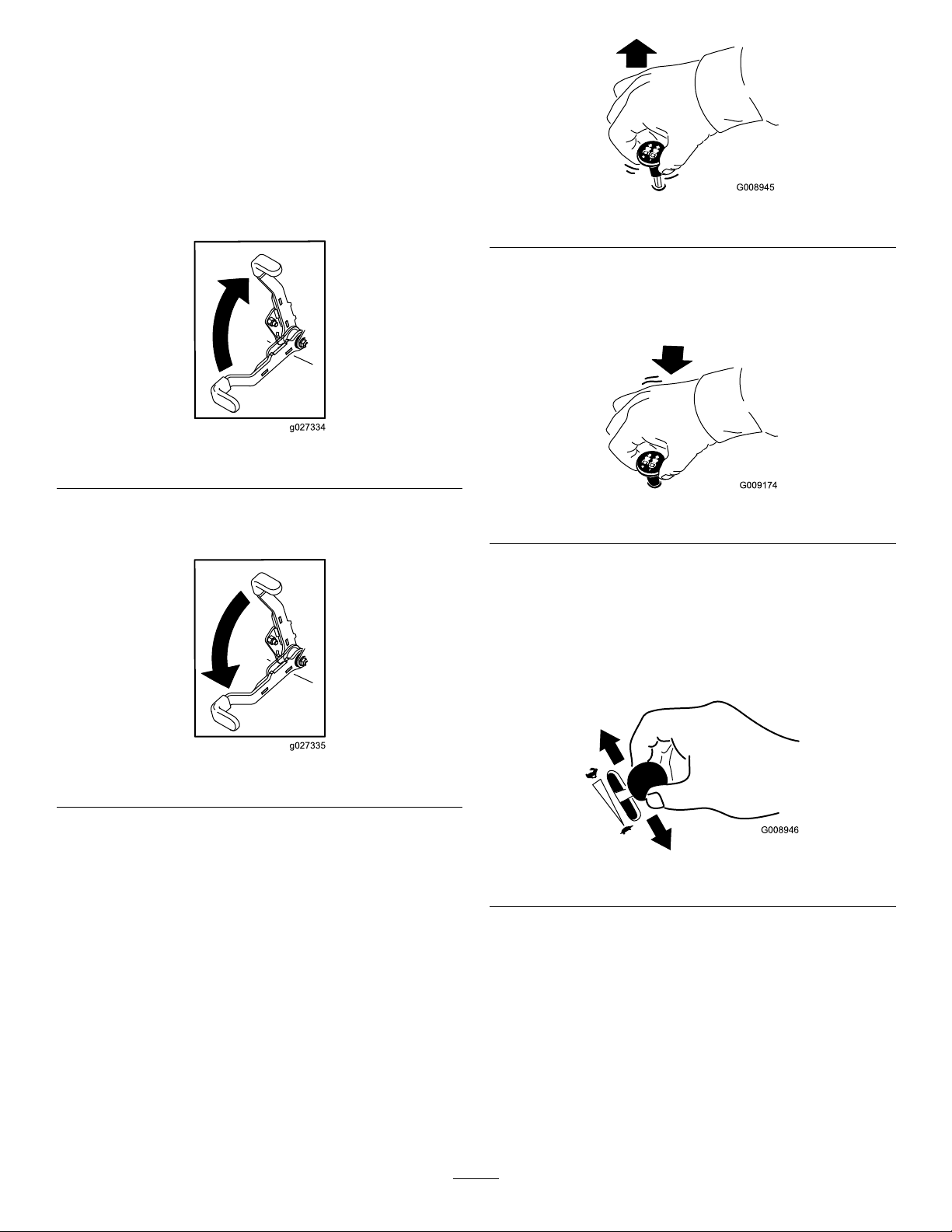
DisengagingtheParkingBrake
g008945
Figure17
DisengagingtheBlade-Control
Switch(PTO)
g027334
g009174
Figure18
OperatingtheThrottle
YoucanmovethethrottlecontrolbetweenFASTand
SLOWpositions(Figure19).
Figure16
OperatingtheMower
Blade-ControlSwitch(PTO)
Theblade-controlswitch(PTO)startsandstopsthe
mowerbladesandanypoweredattachments.
EngagingtheBlade-Control
Switch(PTO)
Note:Engagingtheblade-controlswitch(PTO)with
thethrottlepositionathalforlesscausesexcessive
weartothedrivebelts.
AlwaysusetheFASTpositionwhenengagingthePTO.
g027335
g008946
Figure19
24
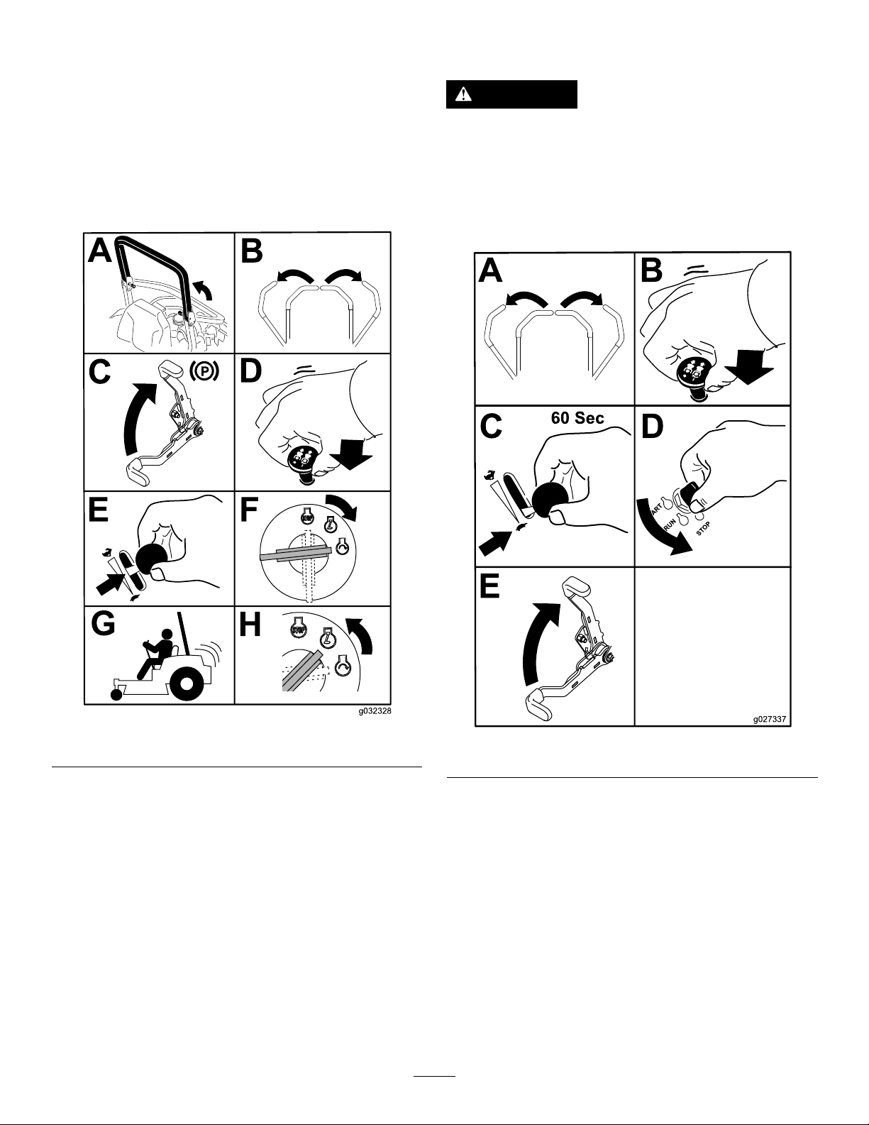
StartingtheEngine
Important:Donotengagethestarterformore
than5secondsatatime.Iftheenginefailsto
start,wait15secondsbetweenattempts.Failure
tofollowtheseinstructionscanburnoutthe
startermotor.
Note:Y oumayneedmultipleattemptstostartthe
enginethersttimeafteraddingfueltoanemptyfuel
system.
ShuttingOfftheEngine
CAUTION
Childrenorbystandersmaybeinjuredifthey
moveorattempttooperatethemachinewhile
itisunattended.
Alwaysremovethekeyandengagethe
parkingbrakewhenleavingthemachine
unattended.
Figure20
g032328
Figure21
g027337
Important:Makesurethatthefuel-shutoffvalve
isclosedbeforetransportingorstoringthe
machine,asfuelleakagemayoccur.Engagethe
parkingbrakebeforetransporting.Makesurethat
youremovethekeyasthefuelpumpmayrunand
causethebatterytolosecharge.
25

UsingtheMotion-Control
WARNING
Levers
Themachinecanspinveryrapidly.You
maylosecontrolofthemachineandcause
personalinjuryordamagetothemachine.
•Usecautionwhenmakingturns.
•Slowthemachinedownbeforemaking
sharpturns.
DrivingForward
Note:Theengineshutsoffwhenyoumovethe
traction-controlwiththeparkingbrakeengaged.
Tostopthemachine,pullthemotion-controllevers
totheNEUTRALposition.
1.Disengagetheparkingbrake.
2.Movethemotion-controlleverstothecenter,
unlockedposition.
3.T ogoforward,slowlypushthemotion-control
leversforward(Figure23).
Figure22
1.Motion-control
levers—NEUTRAL-LOCK
position
2.Center,unlockedposition5.Frontofthemachine
3.Forward
4.Reverse
DrivingtheMachine
Thedrivewheelsturnindependently,poweredby
hydraulicmotorsoneachaxle.Y oucanturn1side
inreversewhileyouturntheotherforward,causing
themachinetospinratherthanturn.Thisgreatly
improvesthemachinemaneuverabilitybutmay
requiresometimeforyoutoadapttohowitmoves.
Thethrottlecontrolregulatestheenginespeedas
measuredinrpm(revolutionsperminute).Place
thethrottlecontrolintheFASTpositionforbest
performance.Alwaysoperateinthefullthrottle
positionwhenmowing.
g004532
g008952
Figure23
DrivinginReverse
1.Movethemotion-controlleverstothecenter,
unlockedposition.
2.T ogoinreverse,slowlypullthemotion-control
leversrearward(Figure24).
26

Figure24
UsingtheSideDischarge
Themowerhasahingedgrassdeectorthat
dispersesclippingstothesideanddowntowardthe
turf.
DANGER
Withoutagrassdeector,dischargecover,or
acompletegrass-catcherassemblymounted
inplace,youandothersareexposedtoblade
contactandthrowndebris.Contactwith
rotatingmowerblade(s)andthrowndebris
willcauseinjuryordeath.
•Neverremovethegrassdeectorfromthe
mowerdeckbecausethegrassdeector
routesmaterialdowntowardtheturf.Ifthe
g008953
grassdeectoriseverdamaged,replaceit
immediately.
•Neverputyourhandsorfeetunderthe
mowerdeck.
•Nevertrytoclearthedischargearea
ormowerbladesunlessyoumovethe
blade-controlswitch(PTO)totheOFF
position,rotatethekeyswitchtotheOFF
position,andremovethekeyfromthekey
switch.
•Makesurethatthegrassdeectorisinthe
downposition.
27

AdjustingtheHeightofCut
UsingtheTransportLock
Thetransportlockhas2positions,andisusedwith
thedeck-liftpedal.ThereisaLOCKpositionand
anUNLOCKpositionforthetransportpositionofthe
mowerdeck(Figure25).
AdjustingtheHeight-of-CutPin
Theheight-of-cutisadjustedfrom25to140mm(1
to5-1/2inches)in6mm(1/4inch)incrementsby
relocatingtheclevispinintodifferentholelocations.
1.Movethetransportlocktothelockposition.
2.Pushonthedeck-liftpedalwithyourfoot,and
raisethemowerdecktothetransportposition
(alsothe140mm(5-1/2inch)cuttingheight
position)asshowninFigure26.
3.T oadjust,rotatethepin90degreesandremove
thepinfromtheheight-of-cutbracket(Figure
26).
4.Selectaholeintheheight-of-cutbracket
correspondingtotheheight-of-cutdesired,and
insertthepin(Figure26).
5.Pushonthedecklift,pullbackonthetransport
lock,andslowlylowerthemowerdeck.
Figure25
Transport-LockPositions
1.Transportlockknob3.UNLOCKposition—The
2.LOCKposition—The
mowerdecklocksintothe
transportposition.
mowerdeckdoesnotlock
intothetransportposition.
g027343
Figure26
1.Deck-liftpedal
2.Cut-of-heightpin
g229103
28
3.Transportlock

AdjustingtheAnti-Scalp
Rollers
Wheneveryouchangetheheight-of-cut,adjustthe
heightoftheanti-scalprollers.
1.Parkthemachineonalevelsurface,disengage
theblade-controlswitch,andengagetheparking
brake.
2.Shutofftheengine,removethekey ,andwait
forallmovingpartstostopbeforeleavingthe
operatingposition.
3.Adjusttheanti-scalprollersasshowninFigure
27,Figure28,andFigure29.
Figure27
1.Anti-scalproller4.Flangenut
2.Spacer
3.Bushing
5.Bolt
g029957
Figure29
1.Anti-scalproller4.Flangenut
2.Spacer
3.Bushing
5.Bolt
AdjustingtheFlowBafe
Knob
Thisprocedureappliesonlytomachineswiththe
owbafeknob.Certainmodelshavenutsandbolts
g029955
insteadoftheowbafeknobthatyoucanadjustthe
sameway.
Youcanadjustthemowerdischargeowfordifferent
typesofmowingconditions.Positiontheknoband
bafetogivethebestqualityofcut.
1.Parkthemachineonalevelsurface,disengage
theblade-controlswitch,andengagetheparking
brake.
Figure28
1.Anti-scalproller3.Flangenut
2.Bushing4.Bolt
2.Shutofftheengine,removethekey ,andwait
forallmovingpartstostopbeforeleavingthe
operatingposition.
3.Loosentheknob.
4.Slidetheknobtothedesiredposition.
5.Tightentheknob.
g029956
29

PositioningtheFlowBafe
Thefollowingguresarerecommendationsonly.
Adjustmentsvarybygrasstype,moisturecontent,
andtheheightofthegrass.
Note:Iftheenginepowerdrawsdownandthe
mowergroundspeedisthesame,openthebafe.
PositionA
Thisisthefully-rearposition.Thesuggestedusefor
thispositionisasfollows:
•Short,lightgrassmowingconditions
•Dryconditions
•Smallergrassclippings
•Propelsgrassclippingsfartherawayfromthe
mower
g295811
Figure31
PositionC
PositionB
Thisisthefully-forwardposition.Thesuggesteduse
forthispositionisasfollows:
•Tall,densegrassmowingconditions
•Wetconditions
•Lowerstheengine-powerconsumption
•Allowsincreasedgroundspeedinheavyconditions
g295810
Figure30
Usethispositionwhenbagging.Alwaysalignitwith
thebloweropening.
g295812
Figure32
30

OperatingTips
UsingtheFastThrottleSetting
dropontoyourlawn.T oavoidthis,moveontoa
previouslycutareawiththebladesengagedoryou
candisengagethemowerdeckwhilemovingforward.
Forbestmowingandmaximumaircirculation,operate
theengineattheFASTposition.Airisrequiredto
thoroughlycutgrassclippings,sodonotsetthe
height-of-cutsolowastototallysurroundthemower
deckinuncutgrass.Alwaystrytohave1sideofthe
mowerdeckfreefromuncutgrass,whichallowsair
tobedrawnintothemowerdeck.
CuttingaLawnfortheFirstTime
Cutgrassslightlylongerthannormaltoensurethat
thecuttingheightofthemowerdeckdoesnotscalp
anyunevenground.However,thecuttingheight
usedinthepastisgenerallythebestonetouse.
Whencuttinggrasslongerthan15cm(6inches)tall,
youmaywanttocutthelawntwicetoensurean
acceptablequalityofcut.
CuttingaThirdoftheGrassBlade
Itisbesttocutonlyaboutathirdofthegrassblade.
Cuttingmorethanthatisnotrecommendedunless
grassissparse,oritislatefallwhengrassgrows
moreslowly.
KeepingtheUndersideofthe
MowerDeckClean
Cleanclippingsanddirtfromtheundersideofthe
mowerdeckaftereachuse.Ifgrassanddirtbuildup
insidethemowerdeck,cuttingqualitywilleventually
becomeunsatisfactory.
MaintainingtheBlade(s)
Maintainasharpbladethroughoutthecuttingseason
becauseasharpbladecutscleanlywithouttearingor
shreddingthegrassblades.T earingandshredding
turnsgrassbrownattheedges,whichslowsgrowth
andincreasesthechanceofdisease.Checkthe
mowerbladesaftereachuseforsharpness,and
foranywearordamage.Filedownanynicksand
sharpenthebladesasnecessary.Ifabladeis
damagedorworn,replaceitimmediatelywitha
genuineT ororeplacementblade.
AfterOperation
AlternatingtheMowingDirection
Alternatethemowingdirectiontokeepthegrass
standingstraight.Thisalsohelpsdisperseclippings,
whichenhancesdecompositionandfertilization.
MowingatCorrectIntervals
Grassgrowsatdifferentratesatdifferenttimesof
theyear.T omaintainthesamecuttingheight,mow
moreofteninearlyspring.Asthegrassgrowthrate
slowsinmidsummer,mowlessfrequently.Ifyou
cannotmowforanextendedperiod,rstmowata
highcuttingheight,thenmowagain2dayslaterata
lowerheightsetting.
UsingaSlowerCuttingSpeed
Toimprovecutquality,useaslowergroundspeed
incertainconditions.
AvoidingCuttingTooLow
Whenmowinguneventurf,raisethecuttingheight
toavoidscalpingtheturf.
AfterOperationSafety
GeneralSafety
•Shutofftheengine,removethekey,andwait
forallmovingpartstostopbeforeleavingthe
operator’sposition.Allowthemachinetocool
beforeservicing,adjusting,fueling,cleaning,or
storingit.
•Cleangrassanddebrisfromthecuttingunit,
mufer,drives,grasscatcher,andengine
compartmenttohelppreventres.Cleanupoilor
fuelspills.
•Shutoffthefuelandremovethekeybeforestoring
ortransportingthemachine.
StoppingtheMachine
Ifyoumuststoptheforwardmotionofthemachine
whilemowing,aclumpofgrassclippingsmay
31
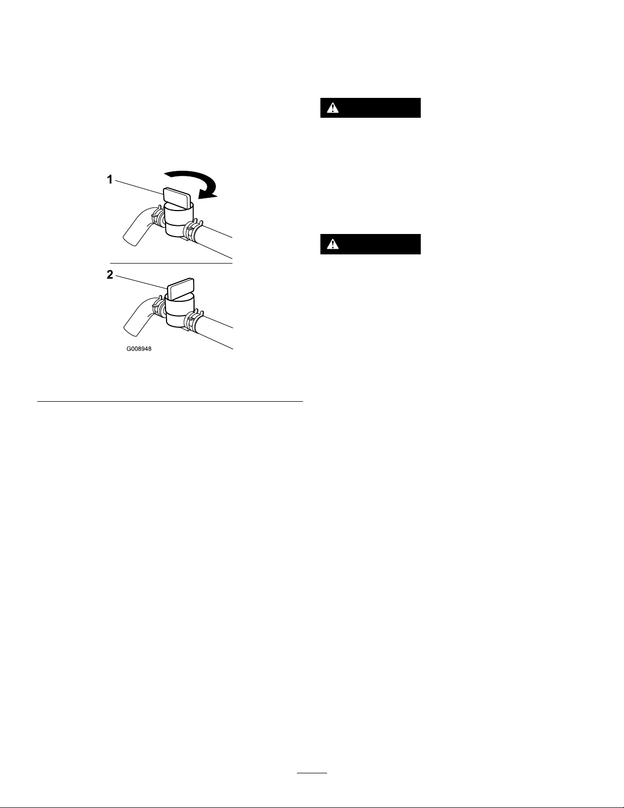
UsingtheFuel-Shutoff
Usingthe
Valve
Thefuel-shutoffvalveislocatedundertheseat.Move
theseatforwardtoaccessit.
Closethefuel-shutoffvalvefortransport,maintenance,
andstorage.
Ensurethatthefuel-shutoffvalveisopenwhen
startingtheengine.
Figure33
1.ONposition2.OFFposition
Drive-Wheel-Release
Valves
WARNING
Handsmaybecomeentangledintherotating
drivecomponentsbelowtheenginedeck,
whichcouldresultinseriousinjury.
Shutofftheengine,removethekey,andallow
allmovingpartstostopbeforeaccessingthe
drive-wheel-releasevalves.
WARNING
Theengineandhydraulic-driveunitscan
becomeveryhot.Touchingahotengineor
hydraulic-driveunitscancausesevereburns.
Allowtheengineandhydraulic-driveunits
tocoolcompletelybeforeaccessingthe
drive-wheel-releasevalves.
g008948
Thedrive-wheel-releasevalvesarelocatedinthe
backofeachhydraulic-driveunit,undertheseat.
Note:Makesurethatthereleasevalvesareinthe
fullyhorizontalpositionwhenoperatingthemachine;
otherwise,severedamagetothehydraulicsystem
canoccur.
1.Parkthemachineonalevelsurface,disengage
theblade-controlswitch,andengagetheparking
brake.
2.Shutofftheengine,removethekey ,andwait
forallmovingpartstostopbeforeleavingthe
operatingposition.
3.Rotatetherelease-valveleversverticallytopush
themachine(Figure34).
Note:Thisallowshydraulicuidtobypassthe
pump,enablingthewheelstoturn.
4.Disengagetheparkingbrakebeforepushing
themachine.
32
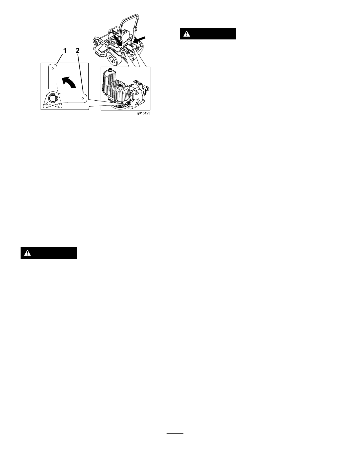
Figure34
1.Verticaltopushthe
machine
5.Rotatethereleasevalvelevershorizontallyto
runthemachine(Figure34).
2.Horizontaltorunthe
machine
SelectingaTrailer
WARNING
Loadingamachineontoatrailerortruck
increasesthepossibilityoftip-overandcould
causeseriousinjuryordeath(Figure35).
•Useonlyafull-widthramp;donotuse
individualrampsforeachsideofthe
machine.
•Donotexceeda15-degreeanglebetween
therampandthegroundorbetweenthe
g015123
rampandthetrailerortruck.
•Ensurethatthelengthoftherampisat
least4timesaslongastheheightofthe
trailerortruckbedtotheground.This
ensuresthattherampangledoesnot
exceed15degreesonatground.
TransportingtheMachine
Useaheavy-dutytrailerortrucktotransportthe
machine.Useafull-widthramp.Ensurethatthetrailer
ortruckhasallthenecessarybrakes,lighting,and
markingasrequiredbylaw.Pleasecarefullyreadall
thesafetyinstructions.Knowingthisinformationcould
helpyouorbystandersavoidinjury.Refertoyour
localordinancesfortrailerandtie-downrequirements.
WARNING
Drivingonthestreetorroadwaywithout
turnsignals,lights,reectivemarkings,ora
slow-moving-vehicleemblemisdangerous
andcanleadtoaccidents,causingpersonal
injury.
Donotdrivethemachineonapublicstreet
orroadway.
33
1.Ifusingatrailer,connectittothetowingvehicle
andconnectthesafetychains.
2.Ifapplicable,connectthetrailerbrakesand
lights.
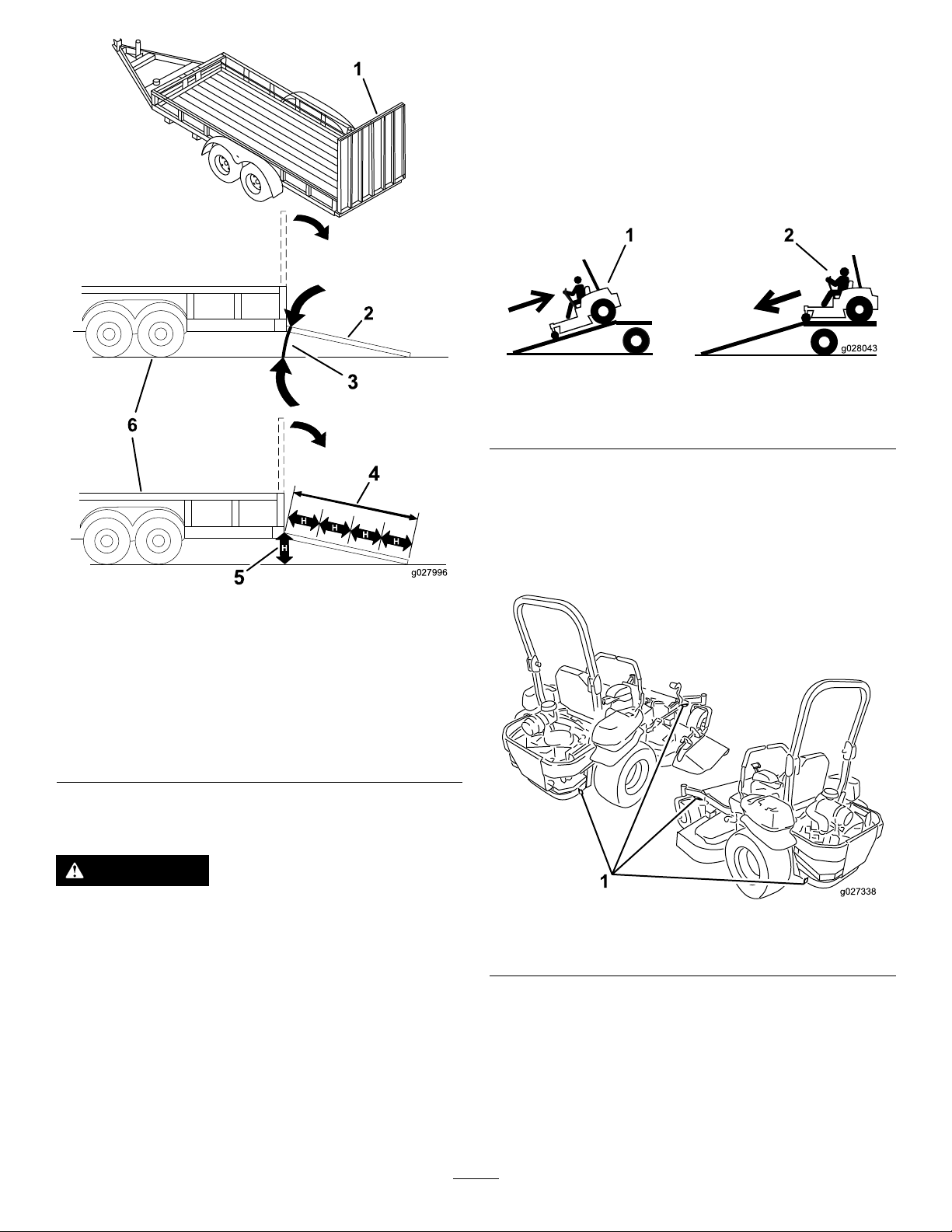
3.Lowertheramp,ensuringthattheangle
betweentherampandthegrounddoesnot
exceed15degrees(Figure35).
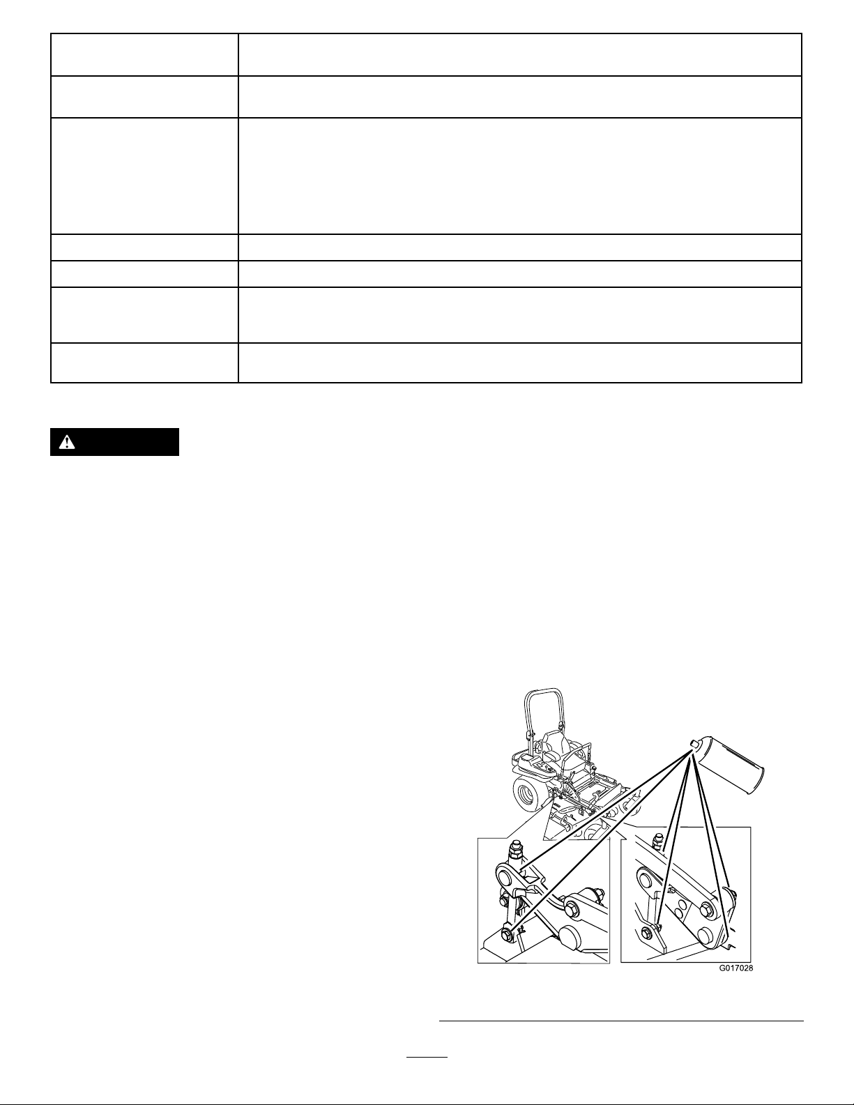
4.Backthemachineuptheramp(Figure36).
Figure36
g028043
1.Full-widthrampinstowed
position
2.Sideviewoffull-width
rampinloadingposition
3.Notgreaterthan
15degrees
LoadingtheMachine
Figure35
4.Rampisatleast4times
aslongastheheightof
thetrailerortruckbedto
theground
5.H=heightofthetraileror
truckbedtotheground
6.Trailer
1.Backthemachineupthe
ramp.
2.Drivethemachineforward
downtheramp.
5.Shutofftheengine,removethekey,andengage
theparkingbrake.
6.Tiedownthemachinenearthefrontcaster
wheelsandtherearframewithstraps,chains,
cable,orropes(Figure37).Refertolocal
regulationsfortie-downrequirements.
g027996
WARNING
Loadingamachineontoatrailerortruck
increasesthepossibilityoftip-overandcould
causeseriousinjuryordeath.
•Useextremecautionwhenoperatinga
machineonaramp.
•Backthemachineuptherampanddriveit
forwarddowntheramp.
•Avoidsuddenaccelerationordeceleration
whiledrivingthemachineonarampas
thiscouldcausealossofcontrolora
tip-oversituation.
g027338
Figure37
1.Tie-downpoints
UnloadingtheMachine
1.Lowertheramp,ensuringthattheangle
betweentherampandthegrounddoesnot
exceed15degrees(Figure35).
2.Drivethemachineforwarddowntheramp
(Figure36).
34

Maintenance
MaintenanceSafety
•Ifyouleavethekeyintheswitch,someonecould
accidentlystarttheengineandseriouslyinjureyou
orotherbystanders.Removethekeyfromthe
switchbeforeyouperformanymaintenance.
•Beforeyouleavetheoperator’sposition,dothe
following:
–Parkthemachineonalevelsurface.
–Disengagethedrives.
–Engagetheparkingbrake.
–Shutofftheengineandremovethekey.
–Allowmachinecomponentstocoolbefore
performingmaintenance.
•Donotallowuntrainedpersonneltoservicethe
machine.
•Keepyourhandsandfeetawayfrommoving
partsorhotsurfaces.Ifpossible,donotmake
adjustmentswiththeenginerunning.
•Carefullyreleasepressurefromcomponentswith
storedenergy.
•Checktheparkingbrakeoperationfrequently.
Adjustandserviceitasrequired.
•Nevertamperwithsafetydevices.Checktheir
properoperationregularly.
•Cleangrassanddebrisfromthecuttingunit,
mufer,drives,grasscatcher,andengine
compartmenttopreventres.
•Cleanupoilorfuelspillsandremovefuel-soaked
debris.
•Donotrelyonhydraulicormechanicaljacksto
supportthemachine;supportthemachinewith
jackstandswheneveryouraisethemachine.
•Keepallpartsingoodworkingcondition
andallhardwaretightened,especiallythe
blade-attachmenthardware.Replaceallwornor
damageddecals.
•Disconnectthebatterybeforerepairingthe
machine.Disconnectthenegativeterminalrst
andthepositivelast.Connectthepositiveterminal
rstandthenegativelast.
•Toensureoptimumperformance,useonly
genuineT ororeplacementpartsandaccessories.
Replacementpartsandaccessoriesmadeby
othermanufacturerscouldbedangerous,and
suchusecouldvoidtheproductwarranty.
RecommendedMaintenanceSchedule(s)
MaintenanceService
Interval
Aftertherst100hours
Aftertherst250hours
Beforeeachuseordaily
Aftereachuse
Every50hours
Every100hours
Every100hoursoryearly,
whichevercomesrst
MaintenanceProcedure
•Checkthewheellug-nuttorque.
•Checkthewheel-hubslotted-nuttorque.
•Adjusttheparkingbrake.
•Changethehydraulicltersandhydraulicuid.
•Checkthesafety-interlocksystem.
•Checktheengine-oillevel.
•Checktheseatbelt.
•Checktherollbarknobs.
•Cleantheenginescreenandtheoilcooler.
•Checkandcleanthehydraulic-unitshrouds.
•Inspecttheblades.
•Cleanthemowerdeck.
•Checkthetirepressure
•Inspectthebeltsforcracksandwear.
•Checkthehydraulic-uidlevel.
•Lubricatethemowerdeck-liftpivots.
•Checkandcleanengine-coolingnsandshrouds.
•Cleantheprimaryairlter(moreoftenindirtyordustyconditions).
•Replaceorcleanandgapthesparkplug.
Every250hours
Every400hours
•Aftertheinitialchange—changethehydraulic-systemltersanduidwhenusing
Mobil115W50uid.(Changeitmoreoftenunderdirtyordustyconditions)
•Greasethecasterpivots(moreoftenindirtyordustyconditions).
35
MaintenanceService
Interval
MaintenanceProcedure
Every400hoursoryearly,
whichevercomesrst
Every500hours
Every600hours
Monthly
Yearly
Yearlyorbeforestorage
•Replacetheprimaryairlter(moreoftenindirtyordustyconditions).
•Replacethefuellter(moreoftenindirtyordustyconditions).
•Changetheengineoilandlter(moreoftenindirtyordustyconditions).
•Checkthewheellug-nuttorque.
•Checkthewheel-hubslotted-nuttorque.
•Adjustthecaster-pivotbearing.
•Adjusttheparkingbrake.
•Aftertheinitialchange—changethehydraulic-systemltersanduidwhenusing
Toro®HYPR-OIL™500uid.(Changeitmoreoftenunderdirtyordustyconditions)
•Replacethesafetyairlter(moreoftenindirtyordustyconditions).
•Checkthebatterycharge.
•Greasethepump-belt-idlerarm.
•Repackthecaster-wheelbearings(moreoftenindirtyordustyconditions).
•Greasingthecaster-wheelhubs.
•Paintchippedsurfaces.
•Checkallmaintenanceprocedureslistedabovebeforestorage.
Important:Refertoyourengineowner'smanualforadditionalmaintenanceprocedures.
CAUTION
Ifyouleavethekeyintheswitch,someonecouldaccidentlystarttheengineandseriously
injureyouorotherbystanders.
Shutofftheengineandremovethekeyfromtheswitchbeforeyouperformanymaintenance.
Lubrication
LubricatingtheMower
Deck-LiftPivots
GreasingtheMachine
Greasethemachinemoreoftenindirtyordusty
conditions.
GreaseType:No.2lithiumormolybdenumgrease
1.Parkthemachineonalevelsurface,disengage
theblade-controlswitch,andengagetheparking
brake.
2.Shutofftheengine,removethekey ,andwait
forallmovingpartstostopbeforeleavingthe
operatingposition.
3.Cleanthegreasettingswitharag.
Note:Scrapeanypaintoffthefrontofthe
tting(s).
4.Connectagreaseguntothetting.
ServiceInterval:Every100hours
Uselightoilorspraylubricanttolubricatethedeck-lift
pivots.
5.Pumpgreaseintothettingsuntilgreasebegins
tooozeoutofthebearings.
6.Wipeupanyexcessgrease.
g017028
Figure38
36
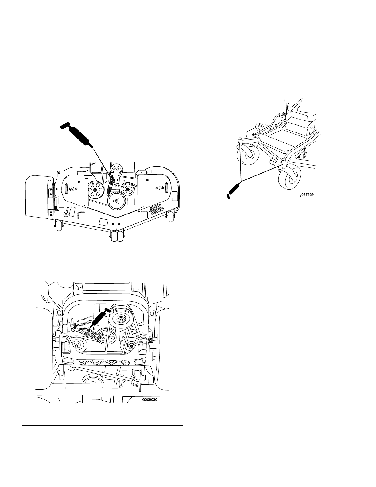
GreasingtheMowerDeck
ServiceInterval:Yearly—Greasethepump-belt-idler
arm.
1.Parkthemachineonalevelsurface,disengage
theblade-controlswitch,andengagetheparking
brake.
Note:Keepthedustcapoffuntilgreasingis
done.
6.Removethehexplug.
7.Threadagreasettingintothehole.
8.Pumpgreaseintothettinguntilitoozesout
aroundthetopbearing.
2.Shutofftheengine,removethekey ,andwait
forallmovingpartstostopbeforeleavingthe
operatingposition.
3.Greasethemowerdeckidler-pulleypivotuntil
greasecomesoutthebottom(Figure39).
Figure39
9.Removethegreasettinginthehole.
10.Installthehexpluganddustcap(Figure41).
g027339
Figure41
11.Greasethecaster-wheelbearings(Figure41).
g295792
GreasingtheCasterPivots
4.Greasethedrive-belt-idlerarm(Figure40).
Figure40
5.Removethedustcapandadjustthecaster
pivots.
ServiceInterval:Every400hours/Y early(whichever
comesrst)(moreoftenindirtyor
dustyconditions).
Yearly—Repackthecaster-wheelbearings
(moreoftenindirtyordustyconditions).
1.Parkthemachineonalevelsurface,disengage
theblade-controlswitch,andengagetheparking
brake.
2.Shutofftheengine,removethekey ,andwait
forallmovingpartstostopbeforeleavingthe
operatingposition.
3.Removethedustcapandadjustthecaster
pivotsandkeepthedustcapoffuntilgreasingis
done;refertoGreasingtheMachine(page36).
4.Removethehexplug.
5.Threadagreasettingintothehole.
g009030
6.Pumpgreaseintothettinguntilitoozesout
aroundthetopbearing.
7.Removethegreasettingfromthehole.Install
thehexplugandcap.
37
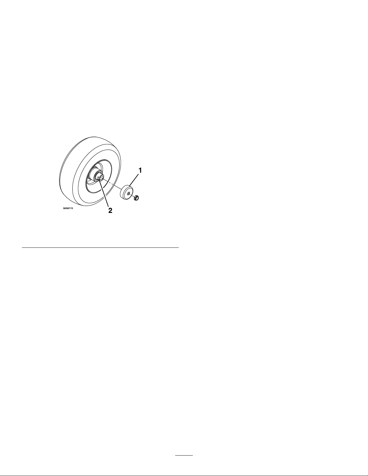
GreasingtheCaster-Wheel
Hubs
ServiceInterval:Y early
1.Parkthemachineonalevelsurface,disengage
theblade-controlswitch,andengagetheparking
brake.
2.Shutofftheengine,removethekey ,andwait
forallmovingpartstostopbeforeleavingthe
operatingposition.
3.Raisethemowerforaccess.
4.Removethecasterwheelfromthecasterforks.
5.Removethesealguardsfromthewheelhub.
Figure42
13.Withtheopenendofthewheelfacingup,ll
theareainsidethewheelaroundtheaxlefullof
general-purposegrease.
14.Insertthesecondbearingandnewsealintothe
wheel.
15.Applyathread-lockingcompoundtothesecond
spacernut,andthreaditontotheaxlewiththe
wrenchatsfacingoutward.
16.T orquethenutto8to9N∙m(75to80in-lb),
loosenthenut,thentorqueitto2to3N∙m(20
to25in-lb).
Note:Makesurethattheaxledoesnotextend
beyondeithernut.
17.Installthesealguardsoverthewheelhub,and
insertthewheelintothecasterfork.
18.Installthecasterboltandtightenthenutfully.
Important:Topreventsealandbearingdamage,
checkthebearingadjustmentoften.Spinthe
castertire.Thetireshouldnotspinfreely(more
than1or2revolutions)orhaveanysideplay.If
thewheelspinsfreely,adjustthetorqueonthe
spacernutuntilthereisaslightamountofdrag.
Applyanotherlayerofthread-lockingcompound.
g006115
1.Sealguard2.Spacernutwithwrench
6.Removeaspacernutfromtheaxleassemblyin
thecasterwheel.
ats
Note:Thread-lockingcompoundhasbeen
appliedtolockthespacernutstotheaxle.
7.Removetheaxle(withtheotherspacernutstill
assembledtoit)fromthewheelassembly.
8.Pryoutsealsandinspectbearingsforwearor
damageandreplaceifnecessary.
9.Packthebearingswithageneral-purpose
grease.
10.Insert1bearingand1newsealintothewheel.
11.Iftheaxleassemblyismissingbothspacernuts,
applyathread-lockingcompoundto1spacer
nutandthreaditontotheaxlewiththewrench
atsfacingoutward.
Note:Donotthreadthespacernutallof
thewayontotheendoftheaxle.Leave
approximately3mm(1/8inch)fromtheouter
surfaceofthespacernuttotheendoftheaxle
insidethenut.
12.Inserttheassemblednutandaxleintothewheel
onthesidewiththenewsealandbearing.
38
EngineMaintenance
EngineSafety
•Keepyourhands,feet,face,clothing,andother
bodypartsawayfromthemuferandotherhot
surfaces.Allowenginecomponentstocoolbefore
performingmaintenance.
•Donotchangetheenginegovernorspeedor
overspeedtheengine.
ServicingtheAirCleaner
ServiceInterval:Every100hoursoryearly,
whichevercomesrst—Cleanthe
primaryairlter(moreoftenindirty
ordustyconditions).
Every400hoursoryearly,whichevercomes
rst—Replacetheprimaryairlter(moreoften
indirtyordustyconditions).
Every600hours/Yearly(whichevercomes
rst)—Replacethesafetyairlter(moreoftenin
dirtyordustyconditions).
Note:Servicetheaircleanermorefrequentlyif
operatingconditionsareextremelydustyorsandy .
RemovingtheFilters
1.Parkthemachineonalevelsurface,disengage
theblade-controlswitch(PTO),andengagethe
parkingbrake.
2.Shutofftheengine,removethekey ,andwait
forallmovingpartstostopbeforeleavingthe
operatingposition.
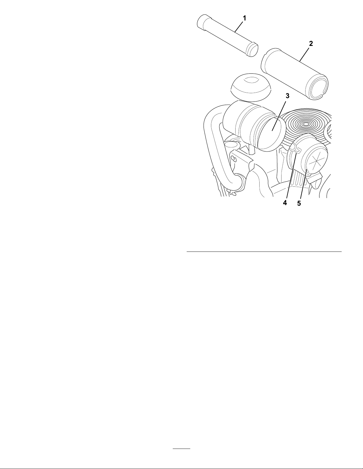
3.Releasethelatchesontheaircleanerandpull
theair-cleanercoverofftheair-cleanerbody
(Figure43).
Figure43
1.Safetylter
2.Primarylter
3.Air-cleanerbody
4.Cleantheinsideoftheair-cleanercoverwith
compressedair.
5.Gentlyslidetheprimarylteroutofthe
air-cleanerbody(Figure43).
4.Latch
5.Air-cleanercover
Note:Avoidknockingthelterintothesideof
thebody.
6.Removethesafetylteronlytoreplaceit.
g366686
InspectingtheFilters
1.Inspectthesafetylter.Ifitisdirty,replaceboth
thesafetyandprimarylters.
Important:Donotattempttocleanthe
safetylter.Ifthesafetylterisdirty,then
theprimarylterisdamaged.
2.Inspecttheprimarylterfordamagebylooking
intothelterwhileshiningabrightlightonthe
outsideofthelter.Iftheprimarylterisdirty ,
bent,ordamaged,replaceit.
Note:Holesinthelterappearasbrightspots.
Donotcleantheprimarylter.
39

InstallingtheFilters
Important:Topreventenginedamage,always
operatetheenginewithbothairltersandthe
coverinstalled.
1.Ifyouareinstallingnewlters,checkeachlter
forshippingdamage.
Note:Donotuseadamagedlter.
2.Ifyouarereplacingtheinnerlter,carefullyslide
itintothelterbody(Figure43).
3.Carefullyslidetheprimarylteroverthesafety
lter(Figure43).
Note:Ensurethattheprimarylterisfully
seatedbypushingontheouterrimwhile
installingit.
Important:Donotpressonthesoft,inside
areaofthelter.
4.Installtheair-cleanercoverandsecurethe
latches(Figure43).
ServicingtheEngineOil
ServiceInterval:Beforeeachuseordaily
Every500hours—Changetheengineoiland
lter(moreoftenindirtyordustyconditions).
Engine-OilSpecications
OilType:Detergentoil(APIserviceSF ,SG,SH,SJ,
orSL)
CrankcaseCapacity:4.73L(5USqt)withalter
change
Viscosity:Seethetablebelow.
Figure44
1.SAE304.Synthetic5W-30
2.10W-305.Vanguard
15W-50
3.5W-30
g366692
synthetic
®
40
CheckingtheEngine-OilLevel
Note:Checktheoilwhentheengineiscold.
Important:Ifyouoverllorunderlltheengine
crankcasewithoilandruntheengine,youmay
damagetheengine.
1.Parkthemachineonalevelsurface,disengage
theblade-controlswitch(PTO),andengagethe
parkingbrake.
2.Shutofftheengine,removethekey ,andwait
forallmovingpartstostopbeforeleavingthe
operatingposition.
Note:Ensurethattheengineiscoolsothatthe
oilhashadtimetodrainintothesump.
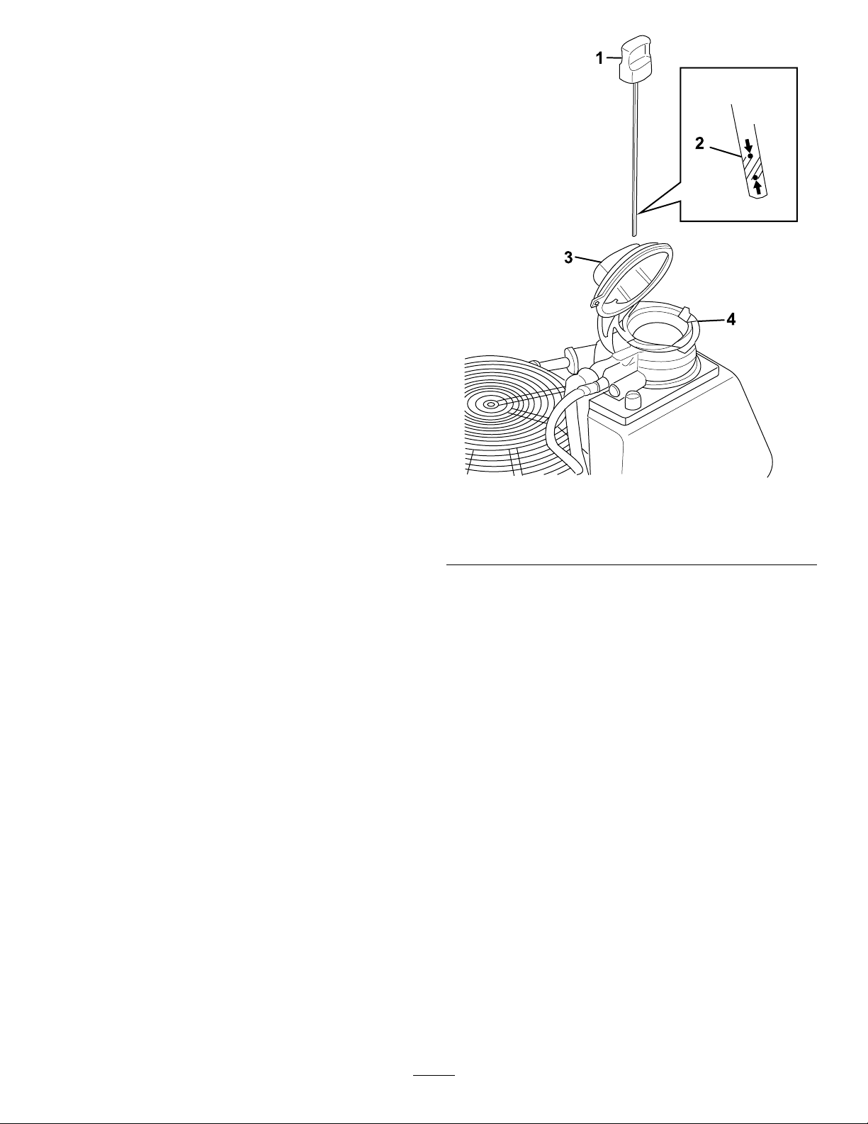
3.Cleantheoilfromthellareaatthetopofthe
tank(Figure45).
4.Removethedipstickandwipeitclean(Figure
45).
5.Fullyinstallthedipstick.
6.Removethedipstickandchecktheoillevel.
Theoilshouldbeatthefull-levelindicatoron
thedipstick(Figure45).
7.Iftheoillevelislow,opentheoil-llcap(Figure
45).
8.Slowlyaddthespeciedengineoilintothetank.
Important:Donotoverll.
9.Afteraddingoil,checktheoillevel.
10.Fullyinstallthedipstick.
11.Closetheoil-llcap.
1.Dipstick
2.Fullline
g366689
Figure45
3.Oil-llcap
4.Oiltank
41

ChangingtheEngineOil
ChangingtheEngine-OilFilter
Note:Disposeoftheusedoilatarecyclingcenter.
1.Starttheengineandletitrunfor5minutes.
Note:Thiswarmstheoilsothatitdrainsbetter.
2.Parkthemachinesothatthedrainsideisslightly
lowerthantheoppositesidetoensurethatthe
oildrainscompletely.
3.Disengagetheblade-controlswitch(PTO)and
engagetheparkingbrake.
4.Shutofftheengine,removethekey ,andwait
forallmovingpartstostopbeforeleavingthe
operatingposition.
5.Removethedipstick(Figure45).
6.Removetheoil-draincap(Figure46).
7.Carefullylowerthedrainhoseintoadrainpan
(Figure46).
8.Aftertheoildrains,installthedraincapand
installthehoseintheuprightposition.
1.Draintheoilfromtheengine;refertoChanging
theEngineOil(page42).
2.Opentheoil-llcapandremovetheengine-oil
lter(Figure47).
Figure46
1.Drainhose3.Drainpan
2.Oil-draincap
g366688
Figure47
1.Dipstick
2.Fullline
3.Filter
g366687
3.Installthenewlter(Figure47).
4.Oil-llcap
5.Oiltank
4.Fillthecrankcasewiththepropertypeofnew
oil;refertoEngine-OilSpecications(page40).
5.Closetheoil-llcap.
6.Startandruntheengine.
Astheenginewarmsup,checkforanyoilleaks.
7.Shutofftheengineandchecktheoillevel;refer
toCheckingtheEngine-OilLevel(page41).
42

ServicingtheSparkPlug(s)
ServiceInterval:Every100hoursoryearly,
whichevercomesrst—Replaceor
cleanandgapthesparkplug.
Ensurethattheairgapbetweenthecenterandside
electrodesiscorrectbeforeinstallingthesparkplug.
Useasparkplugwrenchforremovingandinstalling
thesparkplugandagappingtoolorfeelergaugeto
checkandadjusttheairgap.Installanewsparkplug
ifnecessary.
TypeofSparkPlug:BriggsandStratton491055
AirGap:0.75mm(0.03inch)
RemovingtheSparkPlug(s)
1.Parkthemachineonalevelsurface,disengage
theblade-controlswitch(PTO),andengagethe
parkingbrake.
2.Shutofftheengine,removethekey ,andwait
forallmovingpartstostopbeforeleavingthe
operatingposition.
3.Cleantheareaaroundthebaseoftheplugto
keepdirtanddebrisoutoftheengine.
4.Locateandremovethesparkplug(s)asshown
inFigure48.
Setthegapto0.75mm(0.03inch).
g206628
Figure49
InstallingtheSparkPlug(s)
Figure48
CheckingtheSparkPlug(s)
Important:Donotcleanthesparkplug(s).
Alwaysreplacethesparkplug(s)whenithasa
blackcoating,wornelectrodes,anoilylm,or
cracks.
Ifyouseelightbrownorgrayontheinsulator,the
engineisoperatingproperly.Ablackcoatingonthe
insulatorusuallymeanstheaircleanerisdirty .
g027661
Figure50
g009922
g027478
43

FuelSystem
Maintenance
DANGER
Incertainconditions,fuelisextremely
ammableandhighlyexplosive.Areor
explosionfromfuelcanburnyouandothers
andcandamageproperty.
RefertoFuelSafety(page17)foracomplete
listoffuelrelatedprecautions.
ServicingtheElectronic
Fuel-InjectionSystem
Thismachinecontainsanelectronicfuel-injection
system.Itcontrolsthefuelowunderdifferent
operatingconditions.
1.Fuellter
2.Hoseclamp
g333362
Figure51
3.Fuellinetotheengine
4.Fuellinefromthefueltank
Theelectronic-controlunit(ECU)continuously
monitorstheoperationoftheEFIsystem.
Ifaproblemorfaultwithinthesystemisdetected,the
LEDstatuslightilluminates.TheMIListheredlight
locatedontherightsideofthehourmeter.
Oncethelightilluminates,makeinitialtroubleshooting
checks;refertotheLEDstatuslightsectionunder
Troubleshooting(page70).
Ifthesechecksdonotcorrecttheproblem,further
diagnosisandservicingbyanAuthorizedService
Dealerisnecessary.
ReplacingtheFuelFilter
ServiceInterval:Every400hoursoryearly,
whichevercomesrst
Thefuellterislocatedneartheengineonthefront
orrearsideoftheengine.
1.Parkthemachineonalevelsurface,disengage
theblade-controlswitch,andengagetheparking
brake.
5.Squeezetheendsofthehoseclampstogether
andslidethemawayfromthelter(Figure51).
6.Removethelterfromthefuellines.
7.Installanewlterandmovethehoseclamps
closetothelter(Figure51).
8.Openthefuel-shutoffvalve.
Important:Installthefuellinehosesandsecure
withplastictiesthesameastheywereoriginally
installedatthefactorytokeepthefuellineaway
fromcomponentsthatcancausefuellinedamage.
ServicingtheFuelTank
Donotattempttodrainthefueltank.Ensurethatan
AuthorizedServiceDealerdrainsthefueltankand
servicesanycomponentsofthefuelsystem.
2.Shutofftheengine,removethekey ,andwait
forallmovingpartstostopbeforeleavingthe
operatingposition.
3.Waitforthemachinetocooldown.
4.Closethefuel-shutoffvalveundertheseat
(Figure51).
44

ElectricalSystem
Maintenance
ElectricalSystemSafety
•Disconnectthebatterybeforerepairingthe
machine.Disconnectthenegativeterminalrst
andthepositivelast.Connectthepositiveterminal
rstandthenegativelast.
•Chargethebatteryinanopen,well-ventilated
area,awayfromsparksandames.Unplugthe
chargerbeforeconnectingordisconnectingthe
battery.Wearprotectiveclothinganduseinsulated
tools.
ServicingtheBattery
ServiceInterval:Monthly
RemovingtheBattery
2.Shutofftheengine,removethekey ,andwait
forallmovingpartstostopbeforeleavingthe
operatingposition.
3.RemovethebatteryasshowninFigure52.
g027728
Figure52
WARNING
Batteryterminalsormetaltoolscouldshort
againstmetalmachinecomponentscausing
sparks.Sparkscancausethebatterygasses
toexplode,resultinginpersonalinjury.
•Whenremovingorinstallingthebattery ,
donotallowthebatteryterminalstotouch
anymetalpartsofthemachine.
•Donotallowmetaltoolstoshortbetween
thebatteryterminalsandmetalpartsofthe
machine.
WARNING
Incorrectlyremovingthecablesfrombattery
coulddamagethemachineandcables,
causingsparks.Sparkscancausethebattery
gassestoexplode,resultinginpersonal
injury.
•Alwaysdisconnectthenegative(black)
batterycablebeforedisconnectingthe
positive(red)cable.
•Alwaysconnectthepositive(red)battery
cablebeforeconnectingthenegative
(black)cable.
1.Parkthemachineonalevelsurface,disengage
theblade-controlswitch(PTO),andengagethe
parkingbrake.
45

ChargingtheBattery
InstallingtheBattery
WARNING
Chargingthebatteryproducesgassesthat
canexplode.
Neversmokenearthebatteryandkeepsparks
andamesawayfromthebattery.
Important:Alwayskeepthebatteryfullycharged
(1.265specicgravity).Thisisespecially
importanttopreventbatterydamagewhenthe
temperatureisbelow0°C(32°F).
1.Removethebatteryfromthechassis;referto
RemovingtheBattery(page45).
2.Chargethebatteryfor10to15minutesat25to
30Aorfor30minutesat10A.
Note:Donotoverchargethebattery.
3.Whenthebatteryisfullycharged,unplug
thechargerfromtheelectricaloutlet,then
disconnectthechargerleadsfromthebattery
posts(Figure53).
4.Installthebatteryinthemachineandconnect
thebatterycables;refertoInstallingtheBattery
(page46).
Note:Positionthebatteryinthetraywiththeterminal
postsoppositefromthehydraulictank(Figure54).
g032526
Figure54
Note:Donotrunthemachinewiththebattery
disconnected;electricaldamagemayoccur.
Figure53
1.Positive(+)batterypost3.Red(+)chargerlead
2.Negative(–)batterypost4.Black(–)chargerlead
g000960
46

ServicingtheFuses
DriveSystem
Theelectricalsystemisprotectedbyfuses.Itrequires
nomaintenance,however,ifafuseblowscheckthe
component/circuitforamalfunctionorshort.
Thefusesarelocatedontheconsoletotherightof
theseat(Figure55).
1.T oreplacethefuses,pulloutonthefuseto
removeit.
2.Installanewfuse(Figure55).
Figure55
1.Optionalaccessory(15A)4.Main(25A)
2.Charge(25A)
3.PTO(10A)
5.Console
Maintenance
CheckingtheSeatBelt
ServiceInterval:Beforeeachuseordaily
Inspecttheseatbeltforwear,cuts,andproper
operationoftheretractorandbuckle.Replacethe
seatbeltifitisdamaged.
CheckingtheRoll-Bar
Knobs
ServiceInterval:Beforeeachuseordaily
WARNING
Toavoidinjuryordeathfromrollover,keep
therollbarinthefullyraised,lockedposition
andusetheseatbelt.
Ensurethattheseatissecuredtothe
machine.
g008966
•Checkthatboththemountinghardwareandthe
knobsareingoodworkingcondition.
•Makesurethattheknobsarefullyengagedwith
therollbarintheraisedposition.
Note:Theupperhoopoftherollbarmayneed
tobepushedforwardorpulledrearwardtofully
engagebothknobs(Figure56andFigure57).
47
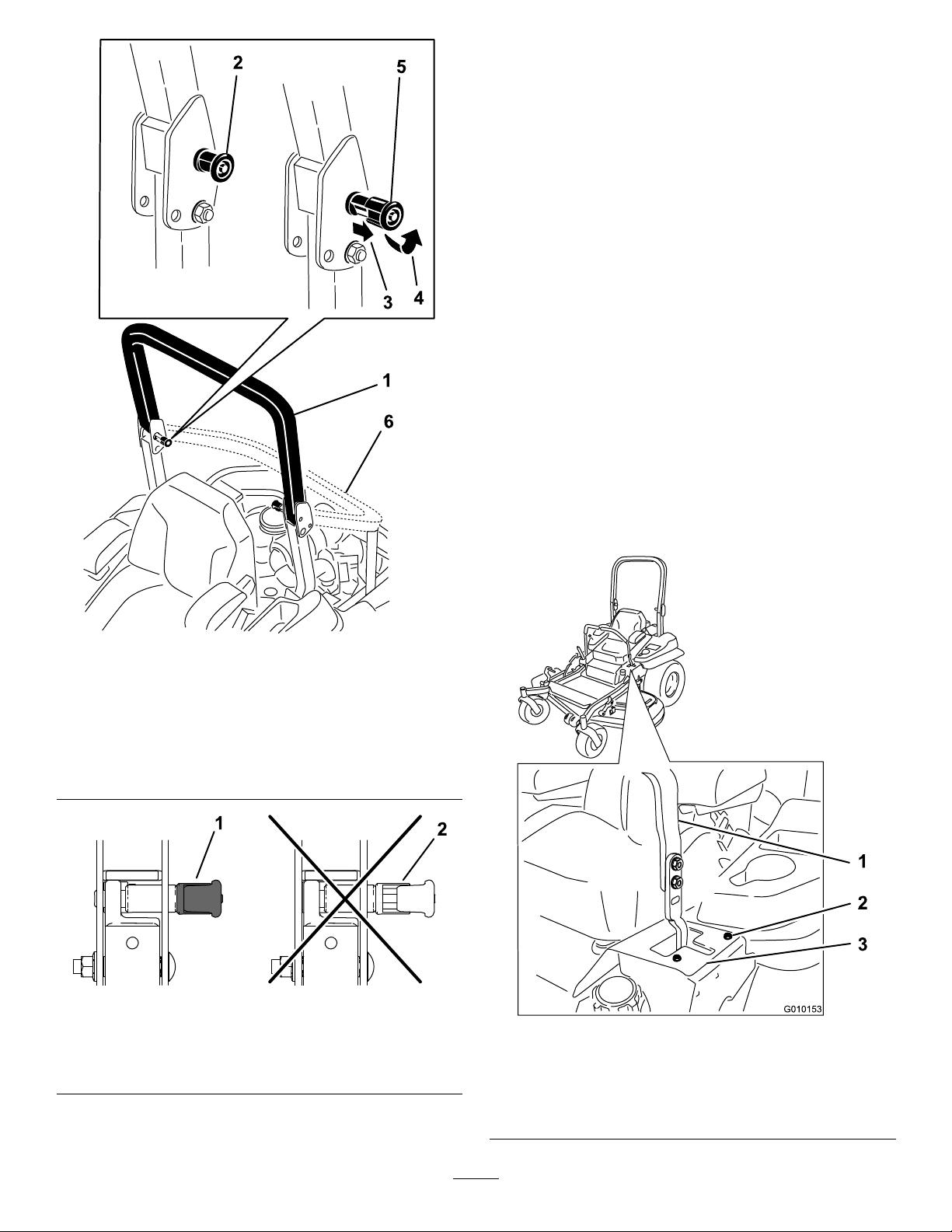
AdjustingtheTracking
1.Disengagetheblade-controlswitch(PTO).
2.Drivetoanopenatarea,movethe
motion-controlleverstotheNEUTRAL-LOCK
position.
3.MovethethrottlemidwaybetweentheFASTand
SLOWpositions.
4.Movebothmotion-controlleversalltheway
forwarduntiltheybothhitthestopsintheT-slot.
5.Checkwhichwaythemachinetracks.
6.Engagetheparkingbrake,shutofftheengine,
andremovethekey.
7.Adjustthestopplatesasneeded.
•Ifthemachinetrackstotheright,loosenthe
boltsandadjusttheleftstopplaterearward
ontheleftT-slotuntilthemachinetracks
straight(Figure58).
•Ifthemachinetrackstotheleft,loosenthe
boltsandadjusttherightstopplaterearward
ontherightT-slotuntilthemachinetracks
straight(Figure58).
1.Rollbarintheupright
position
2.Roll-barknobinthe
latchedposition
3.Pulltheroll-barknobout
androtateit90degrees.
8.Tightenthestopplate(Figure58).
g228804
Figure56
4.Rotatetheroll-barknob90
degrees.
5.Roll-barknobinthe
unlatchedposition
6.Rollbarinthefolded
position
Figure57
1.Engaged2.Partiallyengaged—donot
operatewiththerollbarin
thisposition.
g228981
g010153
Figure58
Leftcontrollevershown
1.Controllever3.Stopplate
2.Bolt
48
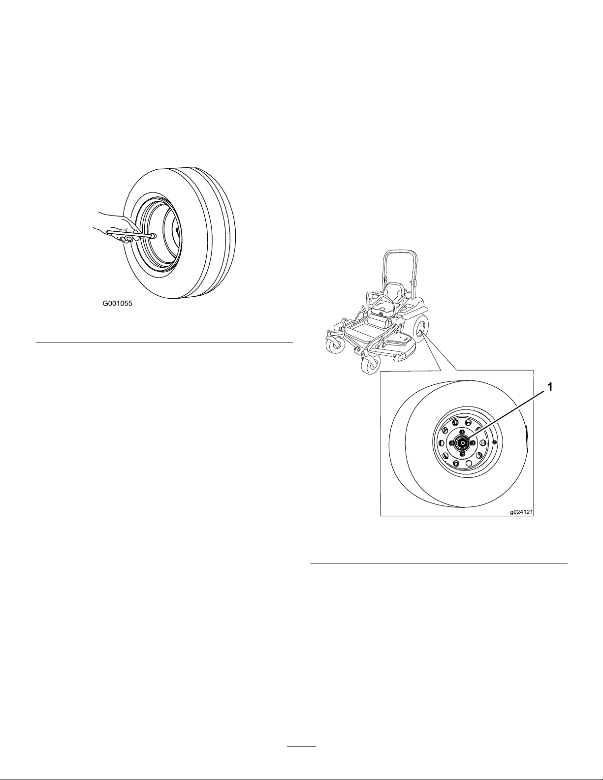
CheckingtheTirePressure
CheckingtheWheelLug
ServiceInterval:Every50hours/Monthly(whichever
comesrst)
Maintaintheairpressureinthereartiresat90kPa
(13psi).Uneventirepressurecancauseunevencut.
Checkthetireswhentheyarecoldtogetthemost
accuratepressurereading.
Note:Thefronttiresaresemi-pneumatictiresanddo
notrequireairpressuremaintenance.
Figure59
Nuts
Checkandtorquethewheellugnutsto122to129
N∙m(90to95ft-lb).
CheckingtheWheel-Hub
SlottedNut
ServiceInterval:Aftertherst100hours
Every500hours
Checkandensurethatthetorqueoftheslottednutis
286to352N∙m(211to260ft-lb).
Note:Donotuseanti-seizecompoundonwheelhub.
g001055
49
g024121
Figure60
1.Slottednut
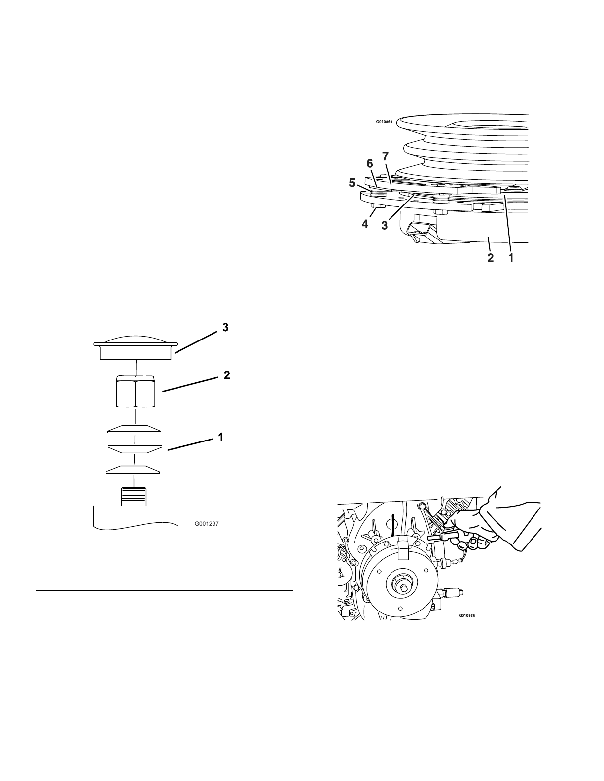
AdjustingtheCaster-Pivot
RemovingtheClutchShim
Bearing
ServiceInterval:Every500hours/Y early(whichever
comesrst)
1.Parkthemachineonalevelsurface,disengage
theblade-controlswitch(PTO),andengagethe
parkingbrake.
2.Shutofftheengine,removethekey ,andwait
forallmovingpartstostopbeforeleavingthe
operatingposition.
3.Removethedustcapfromcasterandtighten
thelocknut(Figure61).
4.Tightenthelocknutuntilthespringwashersare
at,andthenbackoffa1/4turntoproperlyset
thepreloadonthebearings(Figure61).
Important:Makesurethatthespring
washersareinstalledcorrectlyasshownin
Figure61.
5.Installthedustcap(Figure61).
Somelatermodelyearunitshavebeenbuiltwith
clutchesthatcontainabrakeshim.Whentheclutch
brakehasworntothepointwheretheclutchnolonger
engagesconsistently,youcanremovetheshimto
extendtheclutchlife.
g010869
Figure62
1.Armature5.Brakespacer
2.Fieldshell6.Re-gapshim
3.Rotor7.Brakepole
4.Brake-mountingbolt
1.Springwashers
2.Locknut
1.Parkthemachineonalevelsurface,disengage
theblade-controlswitch(PTO),andengagethe
parkingbrake.
2.Shutofftheengine,removethekey ,andwait
forallmovingpartstostopbeforeleavingthe
operatingposition.
3.Usinganaircompressor,blowoutanydebris
fromunderthebrakepoleandaroundthebrake
spacers(Figure63).
g001297
Figure61
3.Dustcap
g010868
Figure63
4.Checktheconditionofthewire-harnessleads,
connectors,andterminals.
Note:Cleanorrepairasnecessary.
50
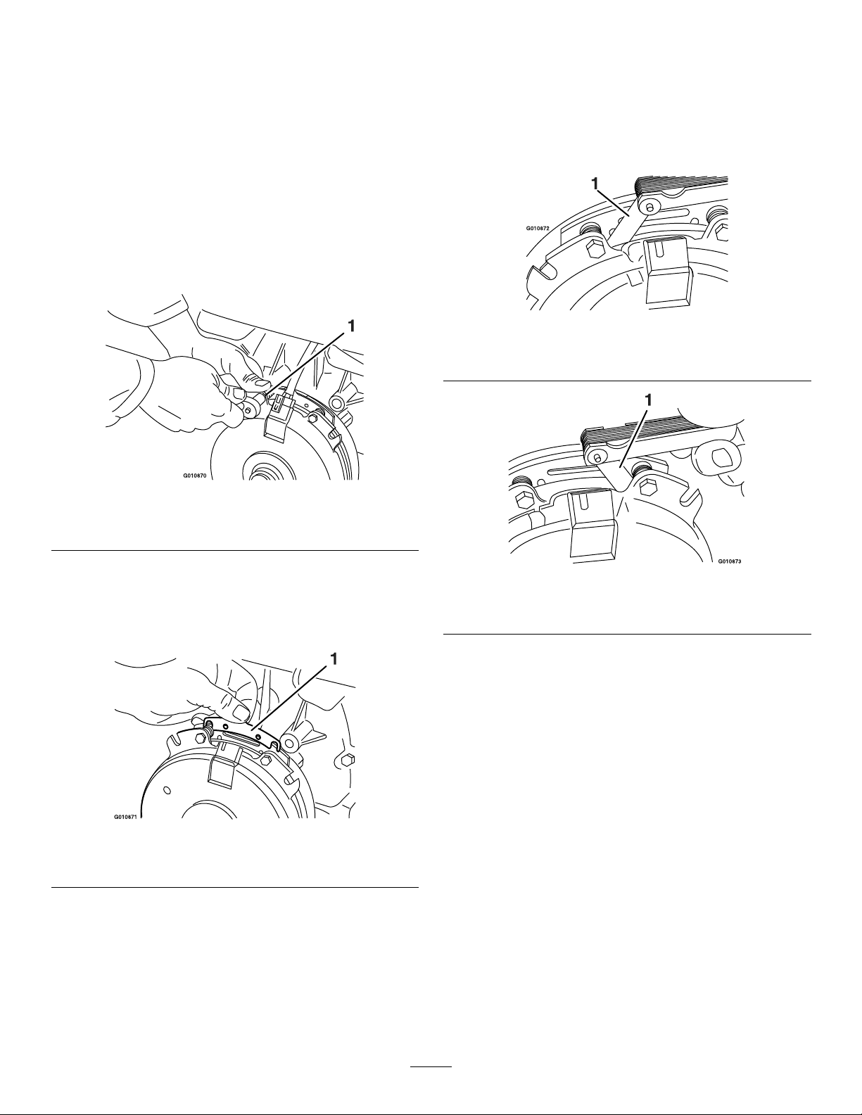
5.Verifythat12Vispresentattheclutchconnector
whentheblade-controlswitch(PTO)switchis
engaged.
therotorandthearmaturefaceonboth
sidesofthebrakepoleasshowninFigure
66andFigure67.
6.Measurethegapbetweentherotorand
armature.Ifthegapisgreaterthan1mm(0.04
inch),dothefollowingsteps:
A.Loosenbothbrake-mountingbolts1/2to1
fullturnasshowninFigure64.
Note:Donotremovethebrakepolefrom
theeldshell/armature.Thebrakepole
hasworntomatchthearmatureandneeds
tocontinuetomatchafteryouremovethe
shimtoensureproperbraketorque.
Figure64
Note:Duetothewaytherotorandthe
armaturefaceswear(peaksandvalleys)it
issometimesdifculttomeasurethegap
accurately.
g010872
Figure66
1.Feelergauge
g010870
1.Brake-mountingbolt
B.Usingneedle-nosepliers,orbyhand,hold
thetabandremovetheshim(Figure65).
Note:Donotdiscardtheshimuntilthe
clutchisfunctioningproperly.
Figure65
1.Shim
C.Usingapneumaticline,blowoutanydebris
fromunderthebrakepoleandaroundthe
brakespacers.
D.T orqueeachbolt(M6x1)to12.3to13.7
N∙m(9.5to10.5ft-lb).
g010873
Figure67
1.Feelergauge
•Ifthegapislessthan0.25mm(0.01
inch),theninstalltheshim.
•Ifthegapissufcient,proceedtothe
safetycheckinstepF.
F.Performthefollowingsafetycheck:
i.Sitontheseatandstarttheengine.
ii.Makesurethatthebladesdonot
engagewiththeblade-controlswitch
g010871
(PTO)intheOFFposition,andthat
theclutchisdisengaged.
Iftheclutchdoesnotdisengage,
installtheshimagain.
iii.Engageanddisengagethe
blade-controlswitch(PTO)10
consecutivetimestoensurethatthe
clutchisfunctioningproperly.
E.Usinga0.25mm(0.01inch)thickfeeler
gauge,verifythatagapispresentbetween
51
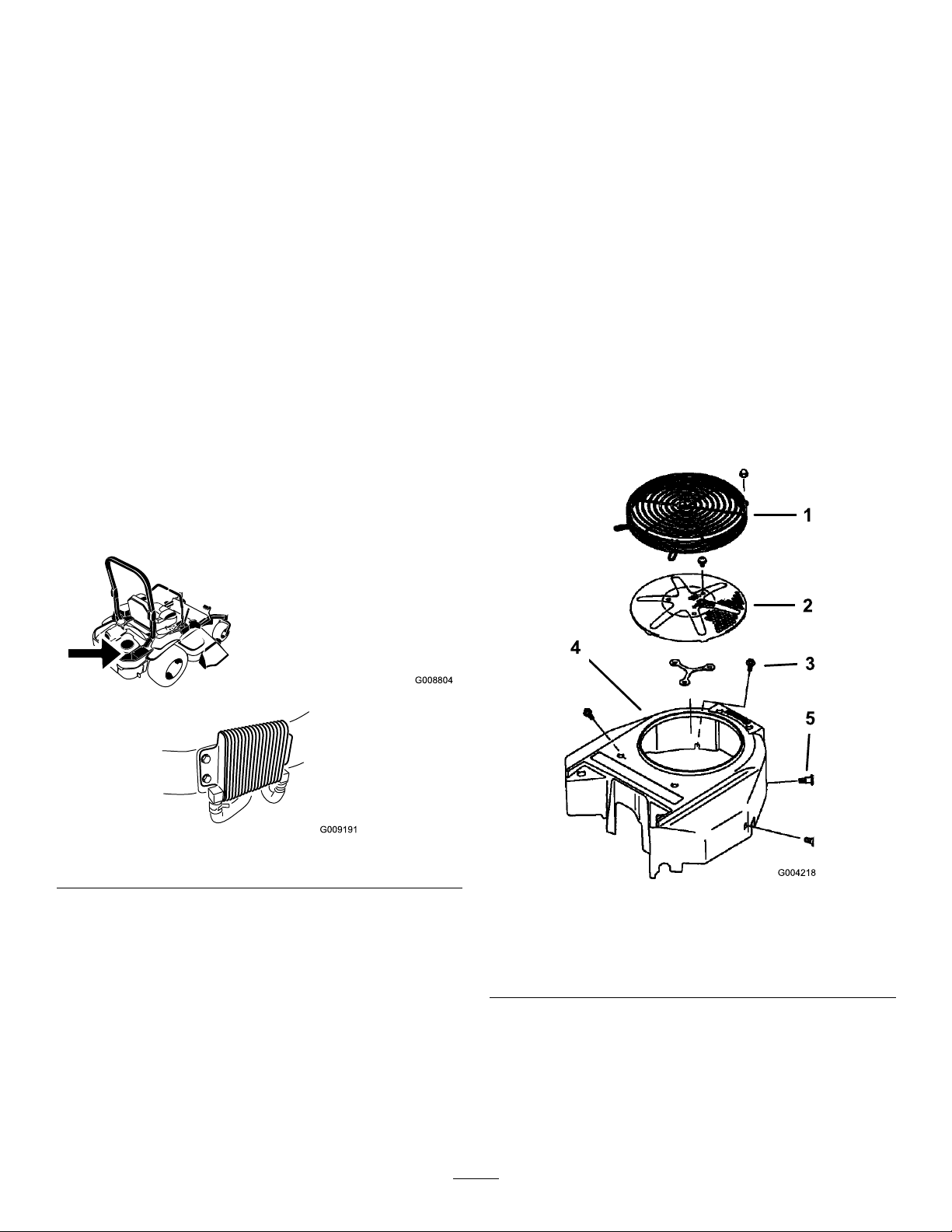
CoolingSystem
Cleaningthe
Maintenance
CoolingSystemSafety
•Swallowingenginecoolantcancausepoisoning;
keepoutofreachfromchildrenandpets.
•Dischargeofhot,pressurizedcoolantortouching
ahotradiatorandsurroundingpartscancause
severeburns.
–Alwaysallowtheenginetocoolatleast15
minutesbeforeremovingtheradiatorcap.
–Usearagwhenopeningtheradiatorcap,and
openthecapslowlytoallowsteamtoescape.
CleaningtheEngineScreen
andEngine-OilCooler
ServiceInterval:Beforeeachuseordaily
Removeanybuildupofgrass,dirt,orotherdebris
fromtheoilcoolerandtheenginescreen(Figure68).
Engine-CoolingFinsand
Shrouds
ServiceInterval:Every100hours/Y early(whichever
comesrst)
1.Parkthemachineonalevelsurface,disengage
theblade-controlswitch(PTO),andengagethe
parkingbrake.
2.Shutofftheengine,removethekey ,andwait
forallmovingpartstostopbeforeleavingthe
operatingposition.
3.Removetheair-intakescreen,therecoilstarter,
andthefanhousing(Figure69).
4.Cleanthedebrisandgrassfromtheengine
parts.
5.Installtheair-intakescreen,therecoilstarter,
andthefanhousing(Figure69).
Figure68
Removeanybuildupofgrass,dirt,orotherdebris
fromtheenginescreen.Thishelpsensureadequate
coolingandcorrectenginespeedandreducesthe
possibilityofoverheatingandmechanicaldamageto
theengine(Figure65).
g008804
g009191
g004218
Figure69
1.Engineguard4.Fanhousing
2.Engineair-intakescreen
3.Bolt
5.Screw
52
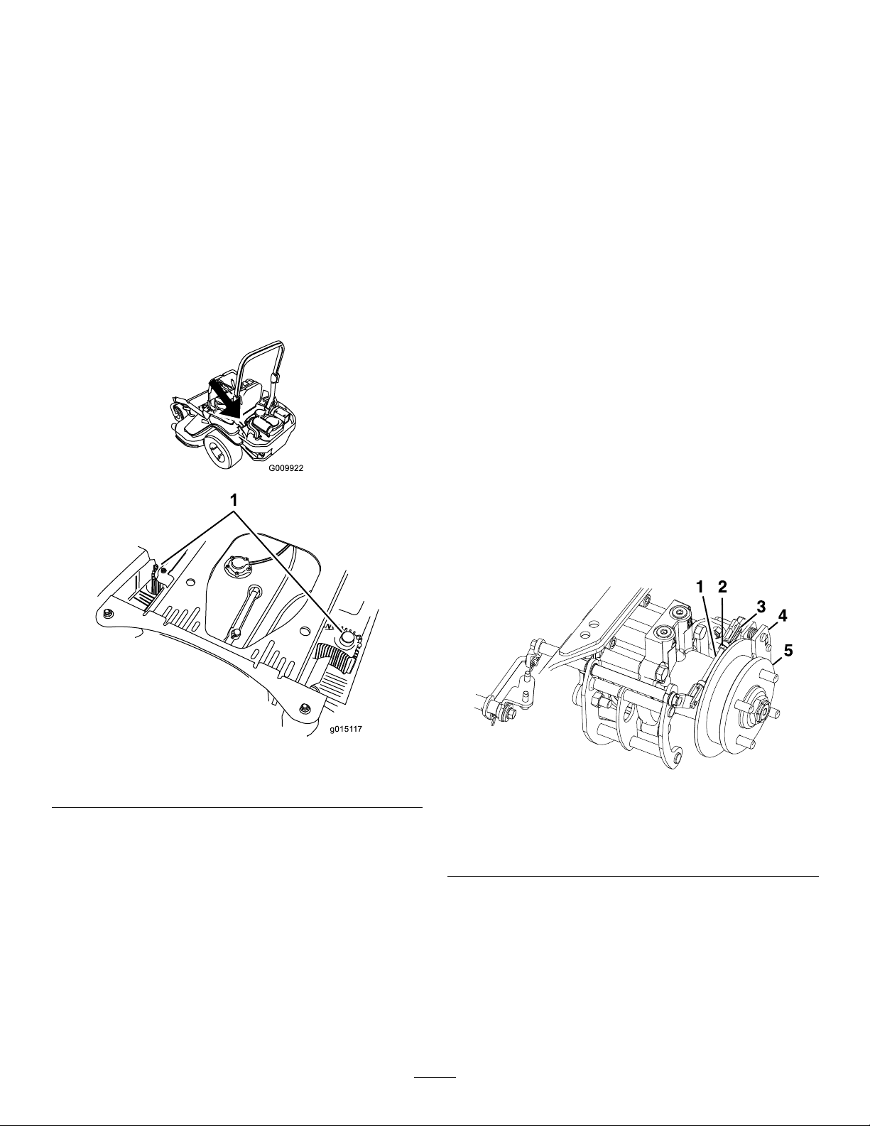
CheckingandCleaningthe
Hydraulic-UnitShrouds
ServiceInterval:Beforeeachuseordaily
1.Parkthemachineonalevelsurface,disengage
theblade-controlswitch(PTO),andengagethe
parkingbrake.
2.Shutofftheengine,removethekey ,andwait
forallmovingpartstostopbeforeleavingthe
operatingposition.
3.Movetheseatforward.
4.Cleanthedebrisandgrassfromthe
hydraulic-unitshrouds(Figure70).
5.Positiontheseat.
BrakeMaintenance
AdjustingtheParking
Brake
ServiceInterval:Aftertherst100hours
Every500hours
Checktoensurethatparkingbrakeisadjusted
properly.Thisproceduremustbefollowedafterthe
rst100hoursorwhenabrakecomponenthasbeen
removedorreplaced.
1.Parkthemachineonalevelsurface,disengage
theblade-controlswitch,andengagetheparking
brake.
2.Shutofftheengine,removethekey ,andwait
forallmovingpartstostopbeforeleavingthe
operatingposition.
3.Raisetherearofthemachineupandsupport
themachinewithjackstands.
4.Removethereartiresfromthemachine.
5.Removeanydebrisfromthebrakearea.
g009922
6.Releasethedrivewheels;refertoUsingthe
Drive-Wheel-ReleaseValves(page32).
7.Disengagetheparkingbrake.
8.Removethespringclevispinfromtherear
linkageandcaliper(Figure71).
1.Hydraulic-unitshrouds
Figure70
g015117
g297209
Figure71
1.Rearlinkage
2.Jamnut5.Wheelhub
3.Springclevispin
9.Loosenthejamnutontherearlinkage.
10.Pushthecaliperleverforwardwithnger
pressureuntilthebrakepadcontactsthehub
rotor.
11.Adjusttherearlinkageuntilthespringclevispin
canbeinsertedintheholeinthecaliperlever.
4.Caliper
Note:Tolengthenthelinkage,rotatetheclevis
1turnoutward.
53
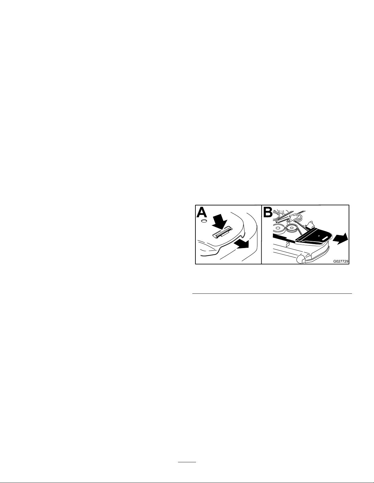
12.Tightenthejamnutontherearlinkage(Figure
71).
13.Ensurethatthewheelhubmovesfreelybetween
thecaliperbrakepads.
14.Repeatssteps8to13fortherightside.
15.Rotatethedrivewheelreleasehandleto
theoperatingposition;refertoUsingthe
Drive-Wheel-ReleaseValves(page32).
16.Installthereartiresandtorquethelugnutsto
129N∙m(95ft-lb).
BeltMaintenance
InspectingtheBelts
ServiceInterval:Every50hours
Replacethebeltifitisworn.Thesignsofawornbelt
includesquealingwhilethebeltisrotating;theblades
slippingwhilecuttinggrass;andfrayededges,burn
marks,andcracksonthebelt.
17.Removethejackstands.
ReplacingtheMowerBelt
1.Parkthemachineonalevelsurface,disengage
theblade-controlswitch(PTO),andengagethe
parkingbrake.
2.Shutofftheengine,removethekey ,andwait
forallmovingpartstostopbeforeleavingthe
operatingposition.
3.Lowerthemowertothe76mm(3inch)height
ofcut.
4.Removethebeltcovers(Figure72).
g027729
Figure72
1.Pushthetabdown.2.Removethebeltcover.
5.Usearatchetinthesquareholeintheidlerarm
toremovetensionontheidlerspring(Figure73).
6.Removethebeltfromthemower-deckpulleys.
7.Removethebeltguideonthespring-loaded
idlerarm(Figure73).
8.Removetheexistingbelt.
9.Installthenewbeltaroundthemowerpulleys
andtheclutchpulleyundertheengine(Figure
73).
54
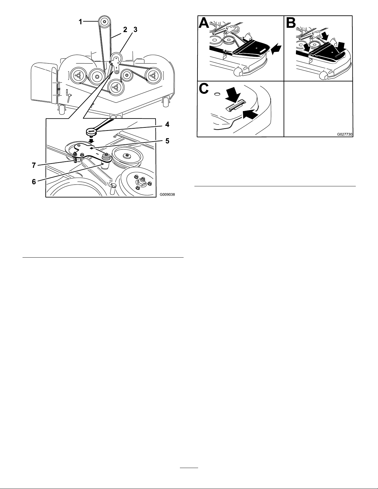
Figure74
g027730
Figure73
1.Clutchpulley5.Squareholeintheidler
2.Mowerbelt
3.Spring-loadedidlerpulley
4.Ratchet
armfortheratchet
6.Idler-greasetting
7.Beltguide
10.Installthebeltguideontheidlerarm(Figure73).
11.Usingtheratchetinthesquarehole,installthe
idlerspring(Figure73).
Note:Makesurethatthespringendsare
seatedintheanchorgrooves.
12.Installthebeltcovers(Figure74).
1.Positionthebeltcover.3.Ensurethatthetabis
underthemetalcatch.
2.Slidethebeltcoverunder
thesidecatches.
g009038
55
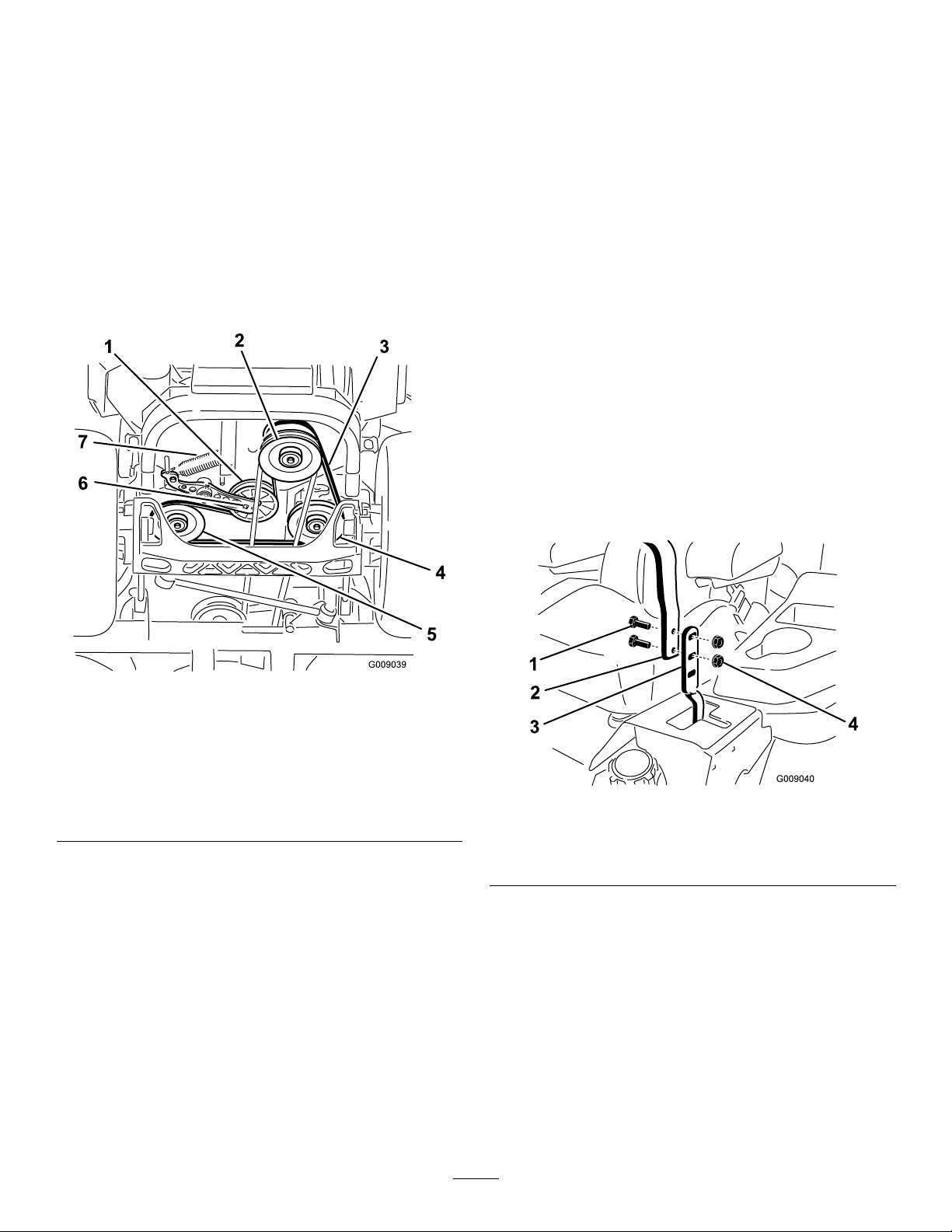
ReplacingtheHydraulic
ControlsSystem
Pump-DriveBelt
1.Parkthemachineonalevelsurface,disengage
theblade-controlswitch(PTO),andengagethe
parkingbrake.
2.Shutofftheengine,removethekey ,andwait
forallmovingpartstostopbeforeleavingthe
operatingposition.
3.Removethemowerbelt;refertoReplacingthe
MowerBelt(page54).
4.Raisethemachineandsupportitwithjack
stands(Figure75).
Maintenance
Adjustingthe
Control-HandlePosition
Thereare2heightpositionsforthecontrol
levers—highandlow.Removetheboltstoadjustthe
heightfortheoperator.
1.Parkthemachineonalevelsurface,disengage
theblade-controlswitch(PTO),andengagethe
parkingbrake.
2.Shutofftheengine,removethekey ,andwait
forallmovingpartstostopbeforeleavingthe
operatingposition.
3.Loosentheboltsandangenutsinstalledinthe
levers(Figure76).
4.Aligntheleversinthefront-to-rearpositionby
bringingtheleverstogethertotheNEUTRAL
position,andslidethemuntiltheyarealigned,
thentightenthebolts(Figure77).
Figure75
1.Idlerpulley
2.Clutchpulley6.Squareholeintheidler
3.Pump-drivebelt7.Idlerspring
4.Righthydraulic-pump
pulley
5.Usearatchetinthesquareholeintheidlerarm
toremovetheidlerspring(Figure75).
6.Unhooktheidlerspringfromtheframe(Figure
75).
7.Removethebeltfromthehydraulic-unit-drive
pulleysandtheenginepulley.
8.Installthenewbeltaroundenginepulleyand
the2drivepulleys.
9.Usingaratchetinthesquareholeintheidler
arm,installtheidlerspringtotheframe(Figure
75).
10.Installthemowerbelt;refertoReplacingthe
MowerBelt(page54).
5.Lefthydraulic-pumppulley
arm
g009039
g009040
Figure76
1.Bolt(2)3.Controllever
2.Handle
4.Nut(2)
56
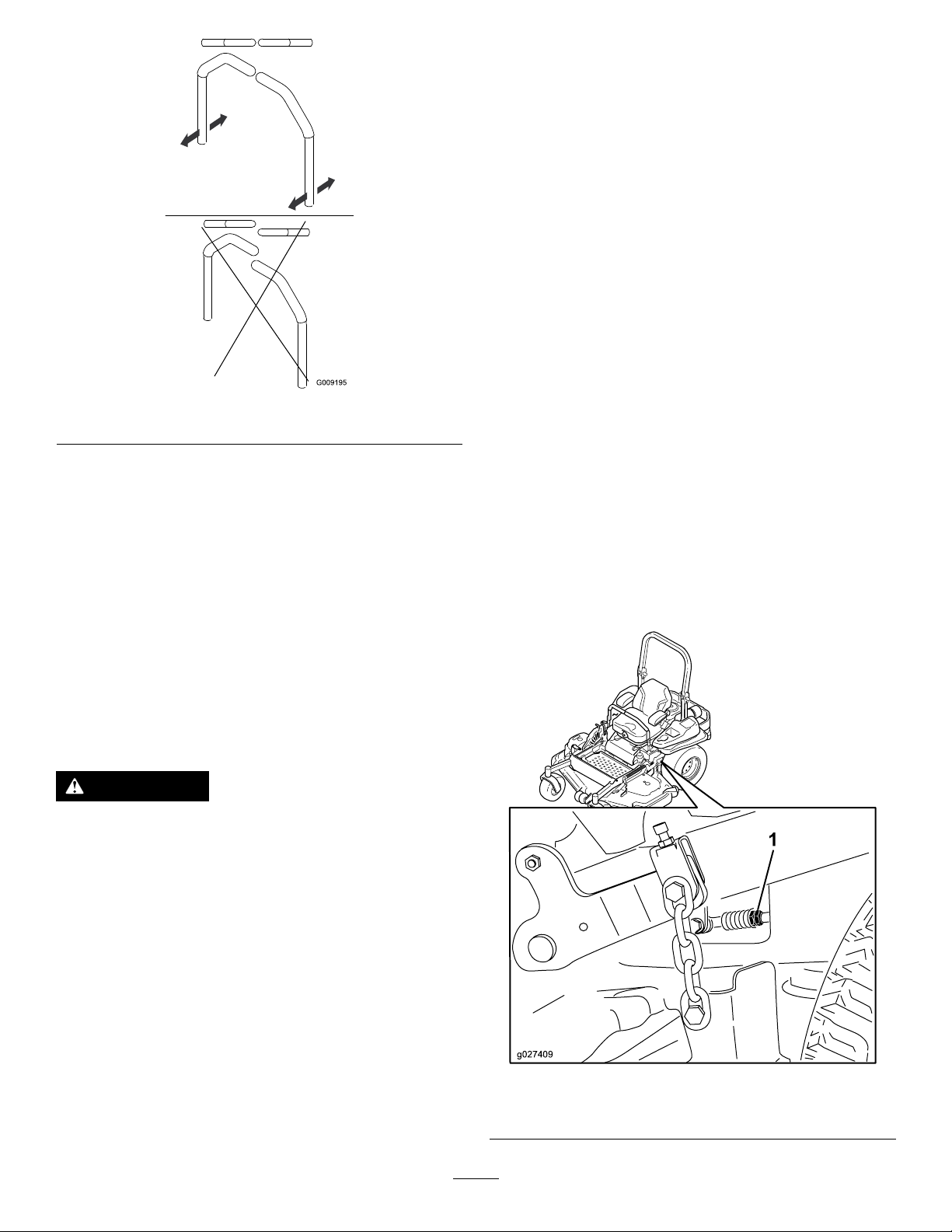
Figure77
4.Raisetherearofthemachineupandsupportit
withjackstands(orequivalentsupport)justhigh
enoughtoallowthedrivewheelstoturnfreely.
5.Removetheelectricalconnectionfromtheseat
safetyswitch,locatedunderthebottomcushion
oftheseat.
Note:Theswitchisapartoftheseatassembly.
6.T emporarilyinstallajumperwireacrossthe
terminalsintheconnectorofthemainwire
harness.
7.Starttheengine,runitatfullthrottle,and
disengagetheparkingbrake.
Note:Beforestartingtheengine,ensurethat
theparkingbrakeisengagedandthatthe
motion-controlleversareout.Youdonothave
tobeintheseat.
g009195
8.Runthemachineatleast5minuteswiththe
driveleversatfullforwardspeedtobringthe
hydraulicuiduptotheoperatingtemperature.
5.Iftheendsofthelevershitagainsteach
other,refertoAdjustingtheMotion-Control
Neutral-LockPivot(page58).
6.Repeattoadjustthecontrollevers.
Adjustingthe
Motion-ControlLinkage
Locatedoneithersideofthemachine,belowtheseat,
arethepump-controllinkages.Rotatingtheendnut
witha1/2-inchdeepsocketwrenchallowsnetuning
adjustmentssothatthemachinedoesnotmovein
neutral.Anyadjustmentsshouldbemadeforneutral
positioningonly.
WARNING
Theenginemustberunningandthedrive
wheelsturningsothatyoucanperformthe
adjustments.Contactwithmovingpartsor
hotsurfacesmaycausepersonalinjury .
Keepyourngers,hands,andclothingclear
ofrotatingcomponentsandhotsurfaces.
Note:Themotion-controlleversmustbein
neutralwhileyouaremakinganyadjustments.
9.Bringthemotion-controlleversintotheNEUTRAL
position.
10.Adjustthepump-control-rodlengthsbyrotating
thedoublenutsontherodintheappropriate
directionuntilthewheelsslightlycreepin
reverse(Figure78).
1.Parkthemachineonalevelsurface,disengage
theblade-controlswitch(PTO),movethe
motion-controlleverstotheNEUTRAL-LOCK
position,andengagetheparkingbrake.
2.Shutofftheengine,removethekey ,andwait
forallmovingpartstostopbeforeleavingthe
operatingposition.
3.Pushthedeck-liftpedal,removetheheight-of-cut
pin,andlowerthemowerdecktotheground
g027409
Figure78
1.Doublenuts
57

11.Movethemotion-controlleverstotheREVERSE
positionandwhileapplyingslightpressureto
thelever,allowthereverse-indicatorspringsto
bringtheleversbacktoneutral.
Note:Thewheelsshouldstopturningorslightly
creepinreverse.
12.Shutoffthemachine.
13.Removethejumperwirefromthewireharness
andplugtheconnectorintotheseatswitch.
14.Removethejackstands.
15.Raisethemowerdeckandinstallthe
height-of-cutpin.
16.Checkandensurethatthemachinedoes
notcreepinneutralwiththeparkingbrake
disengaged.
Adjustingthe
Motion-ControlDamper
Youcanadjustthetopdamper-mountingbolttoobtain
thedesiredmotion-controlleverresistance.Referto
Figure79formountingoptions.
Adjustingthe
Motion-Control
Neutral-LockPivot
Youcanadjusttheangednuttoobtainthedesired
motion-controlleverresistancewhenmovingittothe
NEUTRAL-LOCKposition.SeeFigure80foradjustment
options.
1.Loosenthejamnut.
2.Tightenorloosentheangednuttothedesired
feel.
•Formoreresistance,tightentheangednut.
•Forlessresistance,loosentheangednut
3.Tightenthejamnut.
Figure79
RightMotionControlShown
1.T orquethelocknutto23N∙m(17ft-lb).Theboltmust
protrudepasttheendofthelocknutaftertorquing.
2.Mostresistance(rmestfeel)
3.Damper
4.Mediumresistance(mediumfeel)
5.Leastresistance(softestfeel)
g008621
Figure80
1.Flangednut2.Jamnut
g008620
58

HydraulicSystem
6.Remove1dipstickfromthehydraulicreservoir
(Figure81).
Maintenance
HydraulicSystemSafety
•Seekimmediatemedicalattentionifuidisinjected
intoskin.Injecteduidmustbesurgicallyremoved
withinafewhoursbyadoctor.
•Ensurethatallhydraulic-uidhosesandlinesare
ingoodconditionandallhydraulicconnections
andttingsaretightbeforeapplyingpressureto
thehydraulicsystem.
•Keepyourbodyandhandsawayfrompinhole
leaksornozzlesthatejecthigh-pressurehydraulic
uid.
•Usecardboardorpapertondhydraulicleaks.
•Safelyrelieveallpressureinthehydraulicsystem
beforeperforminganyworkonthehydraulic
system.
Hydraulic-Fluid
7.Wipethedipstickoffandthreadthedipstickinto
thereservoir.
8.Removethedipstickandlookattheend(Figure
81).
Important:Donotoverllthehydraulic
unitswithuid,asdamagemayoccur.Do
notrunthemachinewithuidbelowtheadd
mark.
9.Iftheuidlevelisattheaddmark,slowlypour
onlyenoughuidintothehydraulicreservoirto
raisetheleveltothefullorHline.
10.Installthedipstick.
11.Repeattheprocedurefortheoppositedipstick.
Specications
Hydraulic-FluidType:T oro
hydraulicuidorMobil
®
®
HYPR-OIL
115W-50.
Important:Usethespecieduid.Otheruids
coulddamagethehydraulicsystem.
EachHydraulic-SystemFluidCapacity:1.5L(52
oz)persidewithlterchange
™
500
CheckingtheHydraulic
Fluid
ServiceInterval:Every50hours—Checkthe
hydraulic-uidlevel.
1.Parkthemachineonalevelsurface,disengage
theblade-controlswitch(PTO),andengagethe
parkingbrake.
2.Shutofftheengine,removethekey ,andwait
forallmovingpartstostopbeforeleavingthe
operatingposition.
3.Allowtheengineandthehydraulicsystemto
coolfor10minutes.
g015459
Figure81
Eitherdipstickisusedinthemachine
1.Full3.H—meanshighlevel
2.Add4.Dipsticklocationsunder
seat
Note:Theoillevelonthedipstickisincorrect
whentheoilischeckedandthemachineishot.
4.Movetheseatforward.
5.Cleantheareaaroundthedipsticksof
hydraulic-systemreservoirs(Figure81).
59

ChangingtheHydraulic
FluidandFilters
ServiceInterval:Aftertherst250hours—Change
thehydraulicltersandhydraulic
uid.
Every250hours—Aftertheinitial
change—changethehydraulic-system
ltersanduidwhenusingMobil115W50
uid.(Changeitmoreoftenunderdirtyordusty
conditions)
Every500hours—Aftertheinitial
change—changethehydraulic-system
ltersanduidwhenusingT oro
500uid.(Changeitmoreoftenunderdirtyor
dustyconditions)
Toreplacethehydraulicuid,theltersneedtobe
removed.Replacebothatthesametime;referto
Hydraulic-FluidSpecications(page59)foruid
specications.
1.Parkthemachineonalevelsurface,disengage
theblade-controlswitch,andengagetheparking
brake.
2.Shutofftheengine,removethekey ,andwait
forallmovingpartstostopbeforeleavingthe
operatingposition.
3.Raisethemachineandsupportitwithjack
stands(Figure82).
®
HYPR-OIL
5.Placeadrainpanunderthelter,removethe
oldlter,andwipethesurfaceclean(Figure83).
™
g008968
Figure83
Bottomviewofthemachine
1.Filterlocations
2.Hydrauliclter
6.Applyathincoatofhydraulicuidtotherubber
gasketonthereplacementlter(Figure83).
Figure82
1.Jackstands
4.Removeboththemowerbeltandthepump-drive
belt;refertoReplacingtheMowerBelt(page
54)andReplacingtheHydraulicPump-Drive
Belt(page56).
7.Installthereplacementhydrauliclter.
8.Installthepump-drivebeltandthemowerbelt.
9.Removethejackstandsandlowerthemachine
(Figure82).
10.Adduidtothehydraulicreservoirandcheck
foranyleaks.
11.Cleanupanyspilleduid.
12.Starttheengineandletitrunforabout2minutes
topurgeairfromthesystem.
13.Shutofftheengineandcheckforleaks.
14.Checktheuidlevelwhiletheuidiscold.
15.Ifrequired,adduidtothehydraulicreservoir.
g008970
Note:Donotoverll.
Note:Thispreventsuidfromgettingonthe
belts.
60

MowerDeck
Maintenance
BladeSafety
•Inspectthebladesperiodicallyforwearordamage.
•Usecarewhencheckingtheblades.Wrapthe
bladesorweargloves,andusecautionwhen
servicingtheblades.Onlyreplaceorsharpenthe
blades;neverstraightenorweldthem.
•Onmulti-bladedmachines,takecareasrotating
onebladecancauseotherbladestorotate.
•Replacewornordamagedbladesandboltsinsets
topreservebalance.
ServicingtheCutting
Blades
Toensureasuperiorqualityofcut,keeptheblades
sharp.Forconvenientsharpeningandreplacement,
youmaywanttokeepextrabladesonhand.
BeforeInspectingorServicingthe
Blades
1.Parkthemachineonalevelsurface,disengage
theblade-controlswitch(PTO),andengagethe
parkingbrake.
g006530
Figure84
1.Cuttingedge3.Wear/slotforming
2.Curvedarea4.Crack
2.Shutofftheengine,removethekey ,and
disconnectthespark-plugwiresfromthespark
plugs.
InspectingtheBlades
ServiceInterval:Beforeeachuseordaily
1.Inspectthecuttingedges(Figure84).
2.Iftheedgesarenotsharporhavenicks,remove
andsharpentheblade;refertoSharpeningthe
Blades(page63).
3.Inspecttheblades,especiallyinthecurvedarea.
4.Ifyounoticeanycracks,wear,oraslotforming
inthisarea,immediatelyinstallanewblade
(Figure84).
61

CheckingforBentBlades
Note:Themachinemustbeonalevelsurfacefor
thefollowingprocedure.
1.Raisethemowerdecktothehighest
height-of-cutposition.
2.Whilewearingthicklypaddedgloves,orother
adequatehandprotection,slowlyrotatethe
bladeintoapositionthatallowsyoutomeasure
thedistancebetweenthecuttingedgeandthe
levelsurfacethemachineison(Figure85).
Figure85
1.Deck3.Blade
2.Spindlehousing
g014974
Figure87
1.Blade(sidepreviouslymeasured)
2.Measurement(positionusedpreviously)
3.Opposingsideofbladebeingmovedintomeasurement
position
5.Measurefromthetipofthebladetotheat
surface(Figure88).
Note:Thevarianceshouldbenomorethan
g014972
3mm(1/8inch).
3.Measurefromthetipofthebladetotheat
surface(Figure86).
Figure86
1.Blade(inpositionformeasuring)
2.Levelsurface
3.Measureddistancebetweenbladeandthesurface(A)
4.Rotatethesameblade180degreessothat
theopposingcuttingedgeisnowinthesame
position(Figure87).
g014973
Figure88
1.Oppositebladeedge(inpositionformeasuring)
2.Levelsurface
3.Secondmeasureddistancebetweenbladeandsurface(B)
g014973
A.IfthedifferencebetweenAandBisgreater
than3mm(1/8inch),replacethebladewith
anewblade;refertoRemovingtheBlades
(page63)andInstallingtheBlades(page
63).
Note:Ifabentbladeisreplacedwitha
newblade,andthedimensionobtained
continuestoexceed3mm(1/8inch),the
bladespindlecouldbebent.Contactan
AuthorizedServiceDealerforservice.
B.Ifthevarianceiswithinconstraints,moveto
thenextblade.
6.Repeatthisprocedureoneachblade.
62

RemovingtheBlades
Replacethebladesiftheyhitasolidobject,orifthe
bladeisoutofbalanceorbent.
1.Placeawrenchontheatofthespindleshaftor
holdthebladeendusingaragorthicklypadded
glove.
2.Removethebladebolt,bushing,andbladefrom
thespindleshaft(Figure89).
Note:Ifthebladestaysinahorizontalposition,
thebladeisbalancedandcanbeused.
Note:Ifthebladeisnotbalanced,lesome
metalofftheendofthesailareaonly(Figure90).
g000553
Figure91
1.Blade2.Balancer
3.Repeatthisprocedureuntilthebladeis
balanced.
InstallingtheBlades
1.Installthebushingthroughthebladewiththe
bushingangeonthebottom(grass)sideofthe
blade(Figure92).
Figure89
1.Sailareaoftheblade
2.Blade5.Bladebolt
3.Flatofthespindleshaft
4.Bushing
SharpeningtheBlades
1.Usealetosharpenthecuttingedgeatboth
endsoftheblade(Figure90).
Note:Maintaintheoriginalangle.
Note:Thebladeretainsitsbalanceifthesame
amountofmaterialisremovedfrombothcutting
edges.
Figure90
g295816
g255205
Figure92
1.Bushing
2.Installthebushing/bladeassemblyintothe
spindleshaft(Figure93).
g000552
1.Sharpenatoriginalangle.
2.Checkthebalanceofthebladebyputtingitona
bladebalancer(Figure91).
63
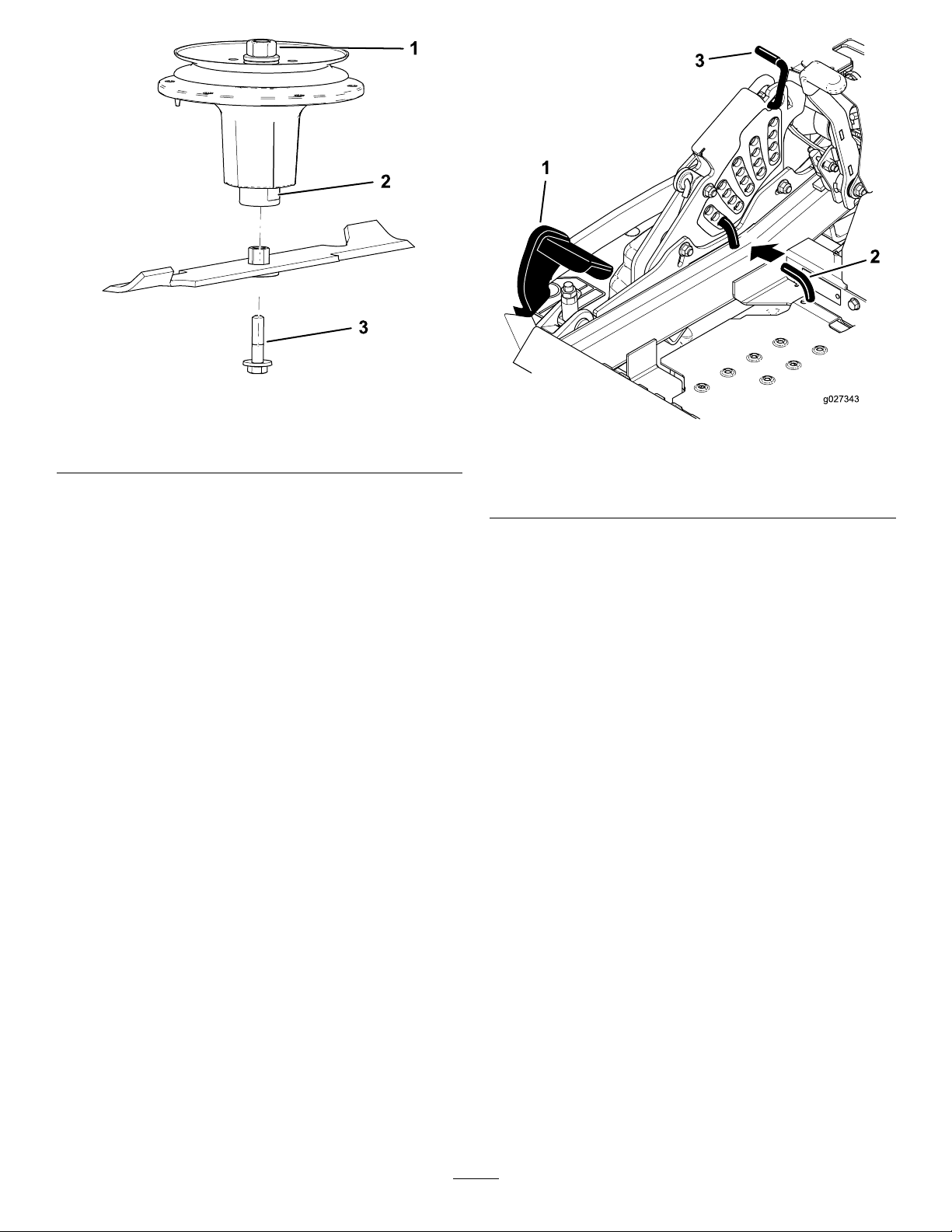
Figure93
g298850
1.T opspindlenut3.Bladebolt
2.Flatofthespindleshaft
3.Applycopper-basedlubricantorgreasetothe
threadsofthebladeboltasneededtoprevent
seizing.Installthebladeboltnger-tight.
4.Placeawrenchontheatofthespindleshaft
andtorquethebladeboltto75to81N∙m(55
to60ft-lb).
LevelingtheMowerDeck
1.Parkthemachineonalevelsurface,disengage
theblade-controlswitch(PTO),andengagethe
parkingbrake.
2.Shutofftheengine,removethekey ,andwait
forallmovingpartstostopbeforeleavingthe
operatingposition.
3.Checkthetirepressureinthedrivetires;referto
CheckingtheTirePressure(page49).
4.Positionthetransportlockinthelatching
position.
Figure94
1.Deck-liftpedal
2.Height-of-cutpin
3.Transportlock
6.Inserttheheight-adjustmentpinintothe7.6cm
(3inches)cutting-heightlocation.
7.Releasethetransportlockandallowthedeckto
lowertothecuttingheight.
8.Raisethedischargechute.
9.Onbothsidesofthedeck,measurefromthe
levelsurfacetothefronttipoftheblade(Postion
A)asshowninFigure95.
Note:Themeasurementshouldread7.6mm
(3inches)
g027343
5.Pushthedeck-liftpedalallthewayforwardand
thedecklatchesatthe14cm(5-1/2inches)
transportposition(Figure94).
64
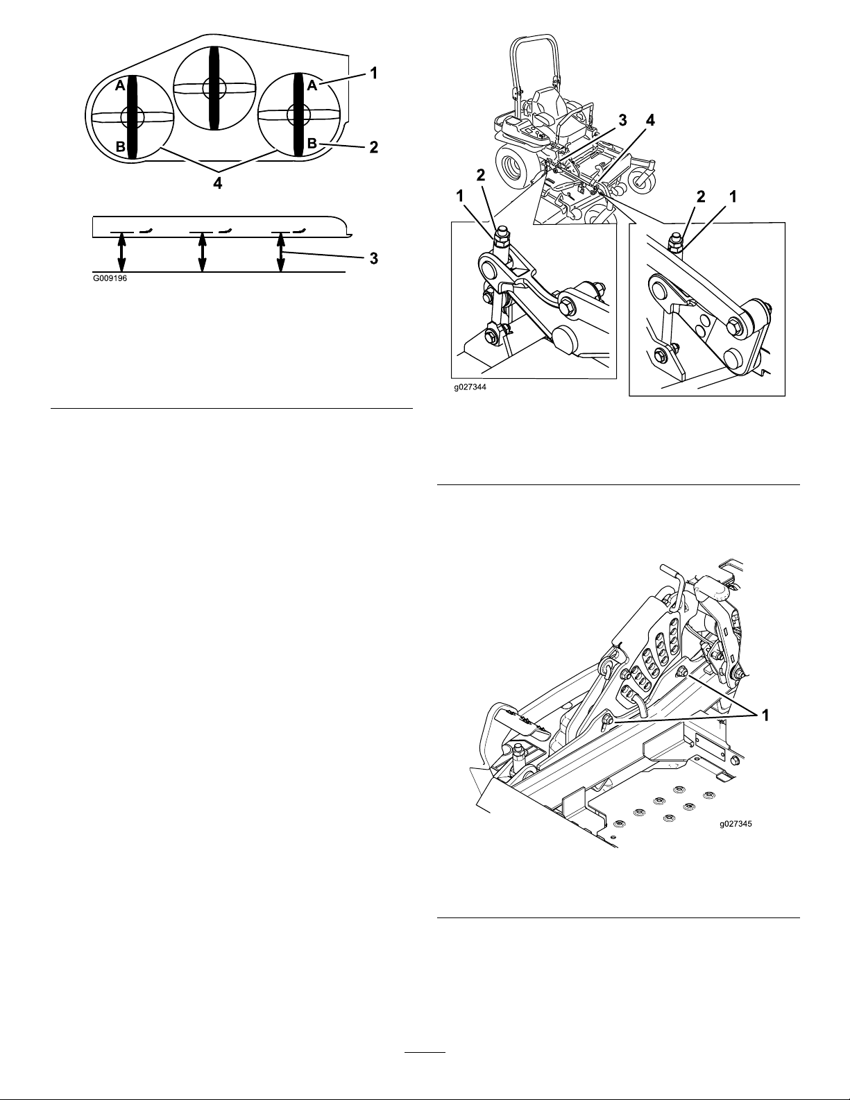
Figure95
g009196
1.7.6cm(3inch)atposition
Aiscorrect
2.8.3cm(3-1/4inch)at
positionBiscorrect
3.Measureherefromthe
bladetiptothehard
surface
4.MeasureatpositionAand
Bonbothsides
10.Fine-tunetheadjustmentnutonthefront
deck-liftassemblybyturningit(Figure96).
Note:T oincreasetheheight,turnthe
adjustmentnutclockwise;todecreasethe
height,turnthenutcounterclockwise.
Note:Ifthefrontdecklinksdonothaveenough
adjustmenttoachieveaccuratecutheight,you
canusethesingle-pointadjustmenttogain
moreadjustment.
g027344
Figure96
1.Adjustmentnut3.Reardeckadjustment
2.Jamnut4.Frontdeckadjustment
11.Toadjustthesingle-pointsystem,loosenthe
2boltsatthebottomoftheheight-of-cutplate
(Figure97).
Figure97
1.Boltsatthebottomoftheheight-of-cutplate
12.Ifthedeckistoolow,tightenthe
single-point-adjustmentboltbyrotatingit
clockwise.Ifthedeckistoohigh,loosen
thesingle-point-adjustmentboltbyrotatingit
counterclockwise(Figure98).
65
g027345
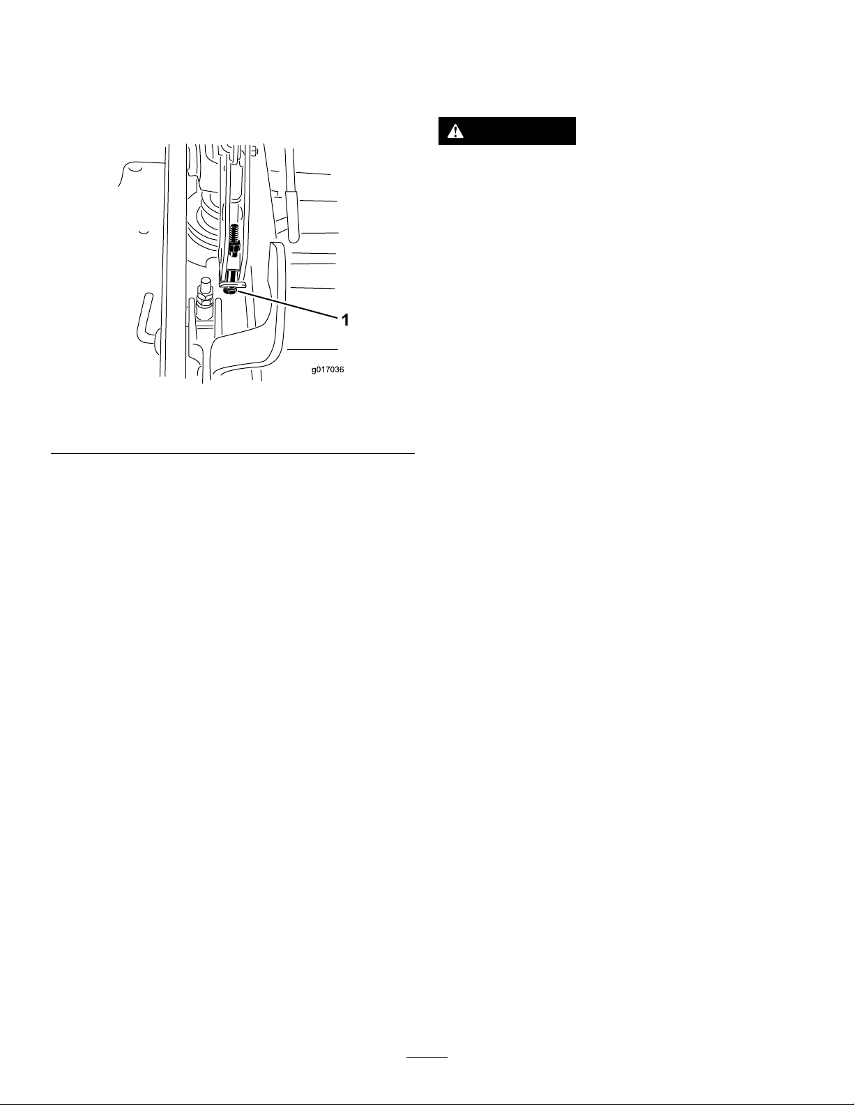
Note:Loosenortightenthesingle-point
adjustmentboltenoughtomovethe
height-of-cutplatemountingboltsatleast1/3
thelengthoftheavailabletravelintheirslots.
Thisregainssomeupanddownadjustmenton
eachofthe4decklinks.
RemovingtheMowerDeck
Lockoutthespring-loadeddeckarmsbeforeservicing
orremovingthemowerdeck.
WARNING
Deck-liftarmassemblieshavestoredenergy.
Removingthedeckwithoutreleasingthe
storedenergycancauseseriousinjuryor
death.
Donotattempttodisassemblethedeckfrom
thefrontframewithoutlockingoutthestored
energy.
1.Parkthemachineonalevelsurface,disengage
theblade-controlswitch(PTO),andengagethe
parkingbrake.
Figure98
1.Single-pointadjustmentbolt
13.Tightenthe2boltsatthebottomofthe
height-of-cutplate(Figure97).
Note:Inmostconditions,thebackbladetip
shouldbeadjusted6.4mm(1/4inch)higher
thanthefront.
14.T orquethe2boltsto37to45N∙m(27to33ft-lb).
15.Onbothsidesofthedeck,measurefromthe
levelsurfacetothebacktipoftheblade(postion
B)asshowninFigure95.
Note:Themeasurementshouldread8.3cm
(3-1/4inches)
16.Finetunethescrewadjusterbyturningittoget
8.3mm(3-1/4inches)height(Figure96).
Toincreasetheheight,turntheadjustmentnut
clockwise;todecrease,turncounterclockwise.
g017036
2.Shutofftheengine,removethekey ,andwait
forallmovingpartstostopbeforeleavingthe
operatingposition.
3.Placetheheightadjustmentpininthe7.6cm(3
inch)cutting-heightlocation.
Note:Thislocksthedeck-liftarmsinthelowest
positionwhenthedeckisremovedandthe
storedenergyinthedeckspringisreleased.
4.Removethebeltcovers.
5.Liftuptheoorpanandinsertaratchetintothe
squareholeinthedeckidler(Figure99).
6.Rotatethedeckidlerclockwiseandremovethe
mowerbelt(Figure99).
17.Measureuntilall4sidesarethecorrectheight.
18.Tightenallofthenutsonthedeck-lift-arm
assemblies.
19.Lowerthedischargechute.
66
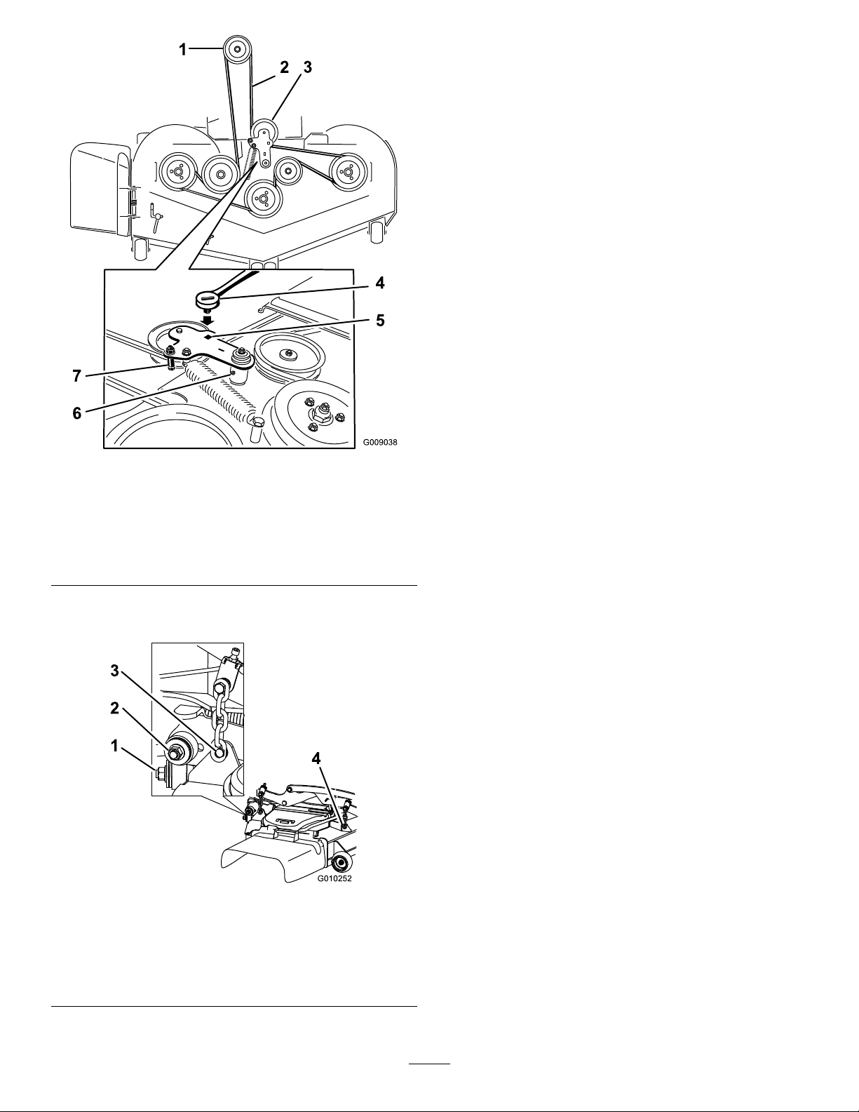
8.Raisethedeckstrutsandsecuretheminthe
raisedposition.
9.Slidethedeckouttotherightsideofthe
machine.
Figure99
1.Clutchpulley5.Squareholeintheidler
2.Mowerbelt
3.Spring-loadedidlerpulley
4.Ratchet
armfortheratchet
6.Idlergreasetting
7.Beltguide
7.Removeandretainthehardwareonbothsides
ofthedeckasshowninFigure100.
g009038
Figure100
1.Rightstabilizer
2.Deckstrut(rightsideshown)
3.Removetheshoulderboltandnut.
4.Removetheshoulderboltandnut.
g010252
67
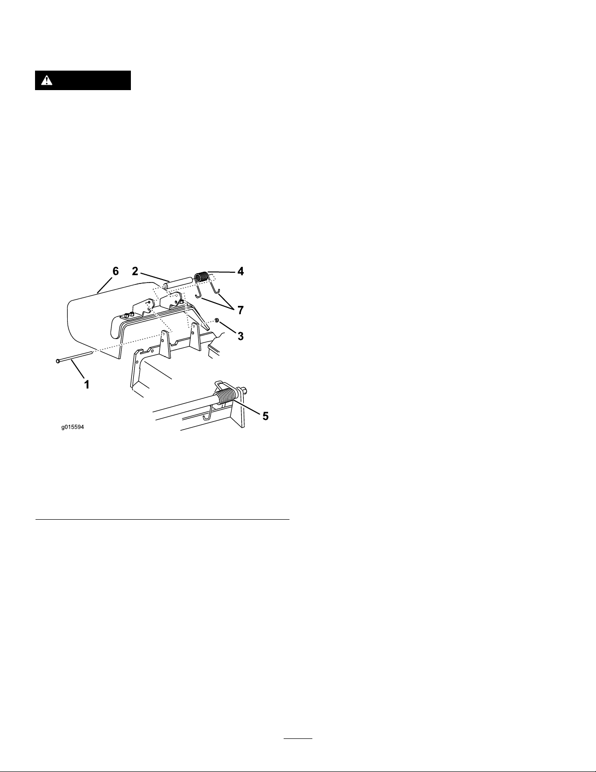
ReplacingtheGrass
Deector
Cleaning
WARNING
Anuncovereddischargeopeningcouldallow
themachinetothrowobjectstowardyouor
bystanders,resultinginseriousinjury.Also,
contactwiththebladecouldoccur.
Neveroperatethemachineunlessyouinstall
amulchplate,dischargedeector,orgrass
collectionsystem.
1.Removethelocknut,bolt,spring,andspacer
holdingthedeectortothepivotbrackets
(Figure101).
2.Removethedamagedorworngrassdeector
(Figure101).
CleaningundertheMower
Deck
ServiceInterval:Aftereachuse
1.Parkthemachineonalevelsurface,disengage
theblade-controlswitch(PTO),andengagethe
parkingbrake.
2.Shutofftheengine,removethekey ,andwait
forallmovingpartstostopbeforeleavingthe
operatingposition.
3.RaisethemowerdecktotheTRANSPORT
position.
DisposingofWaste
Engineoil,batteries,hydraulicuid,andengine
coolantarepollutantstotheenvironment.Disposeof
theseaccordingtoyourstateandlocalregulations.
Figure101
1.Bolt
2.Spacer6.Grassdeector
3.Locknut
4.Spring
3.Placethespacerandthespringontograss
deector.
4.Place1J-hookendofthespringbehindthe
deckedge.
5.Springinstalled
7.J-hookendofspring
Note:Makesurethat1J-hookendofthe
springisinstalledbehindthedeckedgebefore
installingtheboltasshowninFigure101.
5.Installtheboltandthenut.
6.Place1J-hookendofthespringaroundthe
grassdeector(Figure101).
Important:Thegrassdeectormustbeable
torotate.Liftthedeectoruptothefullopen
positionandensurethatitrotatesintothe
fulldownposition.
g015594
68

Storage
StorageSafety
•Shutofftheengine,removethekey,andwait
forallmovingpartstostopbeforeyouleavethe
operator’sposition.Allowthemachinetocool
beforeadjusting,servicing,cleaning,orstoringit.
•Donotstorethemachineorfuelnearamesor
drainthefuelindoorsorinsideanenclosedtrailer.
•Donotstorethemachineorfuelcontainerwhere
thereisanopename,spark,orpilotlight,such
asonawaterheateroronotherappliances.
12.Checktheconditionoftheblades;referto
ServicingtheCuttingBlades(page61).
13.Preparethemachineforstoragewhennon-use
occursover30days.Preparethemachinefor
storageasfollows:
A.Addapetroleum-based
stabilizer/conditionertofuelinthe
tank.Followmixinginstructionsfrom
thestabilizermanufacturer.Donotuse
analcohol-basedstabilizer(ethanolor
methanol).
Note:Afuelstabilizer/conditionerismost
effectivewhenmixedwithfreshfueland
usedatalltimes.
CleaningandStorage
1.Disengagetheblade-controlswitch(PTO),and
engagetheparkingbrake.
2.Shutofftheengine,removethekey ,andwait
forallmovingpartstostopbeforeleavingthe
operatingposition.
3.Removegrassclippings,dirt,andgrimefromthe
externalpartsoftheentiremachine,especially
theengineandhydraulicsystem.Cleandirtand
chafffromtheoutsideoftheenginecylinder
headnsandblowerhousing.
Important:Youcanwashthemachinewith
milddetergentandwater.Donotpressure
washthemachine.Avoidexcessiveuse
ofwater,especiallynearthecontrolpanel,
engine,hydraulicpumps,andmotors.
4.Checktheparkingbrakeoperation;referto
AdjustingtheParkingBrake(page53).
5.Servicetheaircleaner;refertoServicingtheAir
Cleaner(page39).
6.Greasethemachine;refertoLubrication(page
36).
7.Changethecrankcaseoil;refertoServicingthe
EngineOil(page40).
8.Checkthetirepressure;refertoCheckingthe
TirePressure(page49).
9.Changethehydrauliclters;refertoChanging
theHydraulicFluidandFilters(page60).
B.Runtheenginetodistributeconditionedfuel
throughthefuelsystemfor5minutes.
C.Shutofftheengine,allowittocool,and
drainthefueltank.
D.Starttheengineandrunituntilitstops.
E.Disposeoffuelproperly.Recyclethefuel
accordingtolocalcodes.
Important:Donotstorefuelcontaining
stabilizer/conditionerlongerthan
thedurationrecommendedbythe
fuel-stabilizermanufacturer.
14.Removeandchecktheconditionofthespark
plug(s);refertoServicingtheSparkPlug(s)
(page43).Withthesparkplug(s)removedfrom
theengine,pour30ml(2tablespoons)ofengine
oilintothesparkplughole.Usethestarterto
cranktheengineanddistributetheoilinsidethe
cylinder.Installthesparkplug(s).Donotinstall
thewireonthesparkplug(s).
15.Checkandtightenallbolts,nuts,andscrews.
Repairorreplaceanypartthatisdamaged.
16.Paintallscratchedorbaremetalsurfaces.Paint
isavailablefromyourAuthorizedServiceDealer.
17.Storethemachineinaclean,drygarageor
storagearea.Removethekeyfromtheswitch
andkeepitoutofreachofchildrenorother
unauthorizedusers.Coverthemachineto
protectitandkeepitclean.
10.Chargethebattery;refertoChargingtheBattery
(page46).
11.Scrapeanyheavybuildupofgrassanddirt
fromtheundersideofthemower,thenwashthe
mowerwithagardenhose.
Note:Runthemachinewiththeblade-control
switch(PTO)engagedandtheengineathigh
idlefor2to5minutesafterwashing.
69

Troubleshooting
Problem
Themalfunction-indicatorlight(MIL)
comeson.
Thestarterdoesnotcrank.
PossibleCauseCorrectiveAction
1.Theengineistoohot.
2.Thereisoldfuelinthefueltank.2.Usenewfuel.
3.Thefuel-shutoffvalveisnotopen
completely.
4.Theaircleanerisdirty.4.Makesurethattheaircleanerand
5.Thebatteryisnotcharged.
6.Incorrectfuelltersarebeingusedor
thefuelltersaredirty.
7.Theconnectionstothesensors
electronic-controlunit(ECU)andfuel
injectorsarenotsecuredproperly .
8.Thereislowvoltagefromthebattery.
9.Afuseisblown.9.Checkandreplaceanyblownfuses.
1.Theblade-controlswitchisengaged.1.Disengagetheblade-controlswitch.
2.Theparkingbrakeisdisengaged.2.Engagetheparkingbrake.
3.Themotion-controlleversarenotin
theNEUTRAL-LOCKposition.
4.Y ouarenotsittingintheoperator’s
seat.
5.Thebatteryisdead.
6.Theelectricalconnectionsare
corrodedorloose.
7.Afuseisblown.7.Replacethefuse.
8.Arelayorswitchisdamaged.
1.Shutofftheengineandletitcool.
3.Openthefuel-shutoffvalve.
precleanerareclean.Replaceif
necessary.
5.Chargeorreplacethebattery.
6.ContactanAuthorizedServiceDealer.
7.ContactanAuthorizedServiceDealer.
8.Ensurethatyouareusingagood12V
batteryandthatitisfullycharged.
3.Movethemotion-controllevers
outwardtotheNEUTRAL-LOCKposition.
4.Sitontheoperator’sseat.
5.Chargethebattery.
6.Checktheelectricalconnectionsfor
goodcontact.
8.ContactanAuthorizedServiceDealer.
Theenginedoesnotstart,startshard,or
failstokeeprunning.
1.Thefueltankisempty.1.Fillthefueltank.
2.Thefuel-shutoffvalveisclosed.2.Openthefuel-shutoffvalve.
3.Theoillevelinthecrankcaseislow.3.Addoiltothecrankcase.
4.Thethrottleisnotinthecorrect
position.
5.Thereisdirtinthefuellter.5.Replacethefuellter.
6.Thereisdirt,water,orstalefuelisin
thefuelsystem.
7.Theaircleanerisdirty.
8.Theseatswitchisnotfunctioning
properly.
9.Theelectricalconnectionsare
corroded,loose,ordamaged.
10.Therelayorswitchiswornor
damaged.
11.Thesparkplugisfouledorimproperly
gapped.
12.Thespark-plugwireisnotconnected.
4.Besurethatthethrottlecontrolis
midwaybetweentheSLOWandFAST
positions.
6.ContactanAuthorizedServiceDealer.
7.Cleanorreplacetheair-cleaner
element.
8.Checktheseat-switchindicator.
Replacetheseatifnecessary .
9.Checktheelectricalconnections
forgoodcontact.Cleanthe
connectorterminalsthoroughlywith
electrical-contactcleaner,apply
dielectricgrease,andmakethe
appropriateconnections.
10.ContactanAuthorizedServiceDealer .
11.Adjustorreplacethesparkplug.
12.Checkthespark-plugwireconnection.
70

Problem
PossibleCauseCorrectiveAction
Theenginelosespower.
Theengineoverheats.
Themachinepullstotheleftorright(with
themotion-controlleversfullyforward).
Themachinedoesnotdrive.
1.Theengineloadisexcessive.1.Reducethegroundspeed.
2.Theaircleanerisdirty.
3.Theoillevelinthecrankcaseislow.3.Addoiltothecrankcase.
4.Thecoolingnsandtheairpassages
abovetheengineareplugged.
5.Theventholeinthefuelcapisplugged.5.Cleanorreplacethefuelcap.
6.Thereisdirtinthefuellter.6.Replacethefuellter.
7.Thereisdirt,water,orstalefuelinthe
fuelsystem.
1.Theengineloadisexcessive.1.Reducethegroundspeed.
2.Theoillevelinthecrankcaseislow.2.Addoiltothecrankcase.
3.Thecoolingnsandairpassages
undertheengine-blowerhousingare
plugged.
4.Theaircleanerisdirty.
5.Dirt,water,orstalefuelisinthefuel
system.
1.Thetrackingneedsadjustment1.Adjustthetracking.
2.Thetirepressureinthedrivetiresis
notcorrect.
1.Thebypassvalvesarenotclosedtight.1.Tightenthebypassvalves.
2.Thepumpbeltisworn,loose,or
broken.
3.Thepumpbeltisoffapulley.3.Changethebelt.
4.Theidlerspringisbrokenormissing.4.Replacethespring.
5.Thehydraulicuidlevelislowortoo
hot.
2.Cleantheair-cleanerelement.
4.Removetheobstructionfromthe
coolingnsandtheairpassages.
7.ContactanAuthorizedServiceDealer.
3.Removetheobstructionfromthe
coolingnsandairpassages.
4.Cleanorreplacetheair-cleaner
element.
5.ContactanAuthorizedServiceDealer
2.Adjustthetirepressureinthedrive
tires.
2.Changethebelt.
5.Addhydraulicuidtothereservoirsor
letitcooldown.
Themachinevibratesabnormally .
Thecuttingheightisuneven.
1.Thecuttingblade(s)is/arebentor
unbalanced.
2.Theblademountingboltisloose.2.Tightentheblademountingbolt.
3.Theenginemountingboltsareloose.3.Tightentheenginemountingbolts.
4.Theenginepulley ,idlerpulley,orblade
pulleyisloose.
5.Theenginepulleyisdamaged.
6.Thebladespindleisbent.
7.Themotormountislooseorworn.
1.Theblade(s)isnotsharp.1.Sharpentheblade(s).
2.Acuttingblade(s)is/arebent.2.Installanewcuttingblade(s).
3.Themowerisnotlevel.
4.Ananti-scalproller(ifapplicable)isnot
setcorrectly .
5.
Theundersideofthemowerdeckis
dirty.
Thetirepressureisincorrect.
6.
7.Abladespindleisbent.
1.Installnewcuttingblade(s).
4.Tightentheappropriatepulley.
5.ContactanAuthorizedServiceDealer.
6.ContactanAuthorizedServiceDealer.
7.ContactanAuthorizedServiceDealer.
3.Levelthemowerfromside-to-sideand
front-to-rear.
4.Adjusttheanti-scalpwheelheight.
5.
Cleantheundersideofthemower
deck.
Adjustthetirepressure.
6.
7.ContactanAuthorizedServiceDealer.
71

Problem
PossibleCauseCorrectiveAction
Thebladesdonotrotate.
Theclutchdoesnotengage.
1.Themowerdeckbeltisdamaged,
worn,loose,orbroken.
2.Themowerdeckbeltisoffthepulley.
3.Thepumpdrivebeltisworn,loose,or
broken.
4.Theidlerspringisbrokenormissing.4.Replacethespring.
1.Thefuseisblown.1.Replacethefuse.Checkthecoil
2.Thereislowvoltagesupplyatthe
clutch.
3.Thecoilisdamaged.3.Replacetheclutch.
4.Thereisinadequatecurrentsupply.4.Repairorreplacetheclutchlead
5.Therotor/armatureairgapistoolarge.
1.Installanewdeckbelt.
2.Installthemowerbeltonthedeck
pulleyandchecktheidlerpulley,idler
arm,andspringforcorrectposition
andfunction.
3.Checkthebelttensionorinstallanew
belt.
resistance,batterycharge,charging
system,andwiringconnections,and
replacecomponentsifnecessary.
2.Checkthecoilresistance,battery
charge,chargingsystem,andwiring
connectionsandreplacepartsif
necessary.
wireorelectricalsystem.Cleanthe
connectorcontacts.
5.Removetheshimorreplacetheclutch.
72
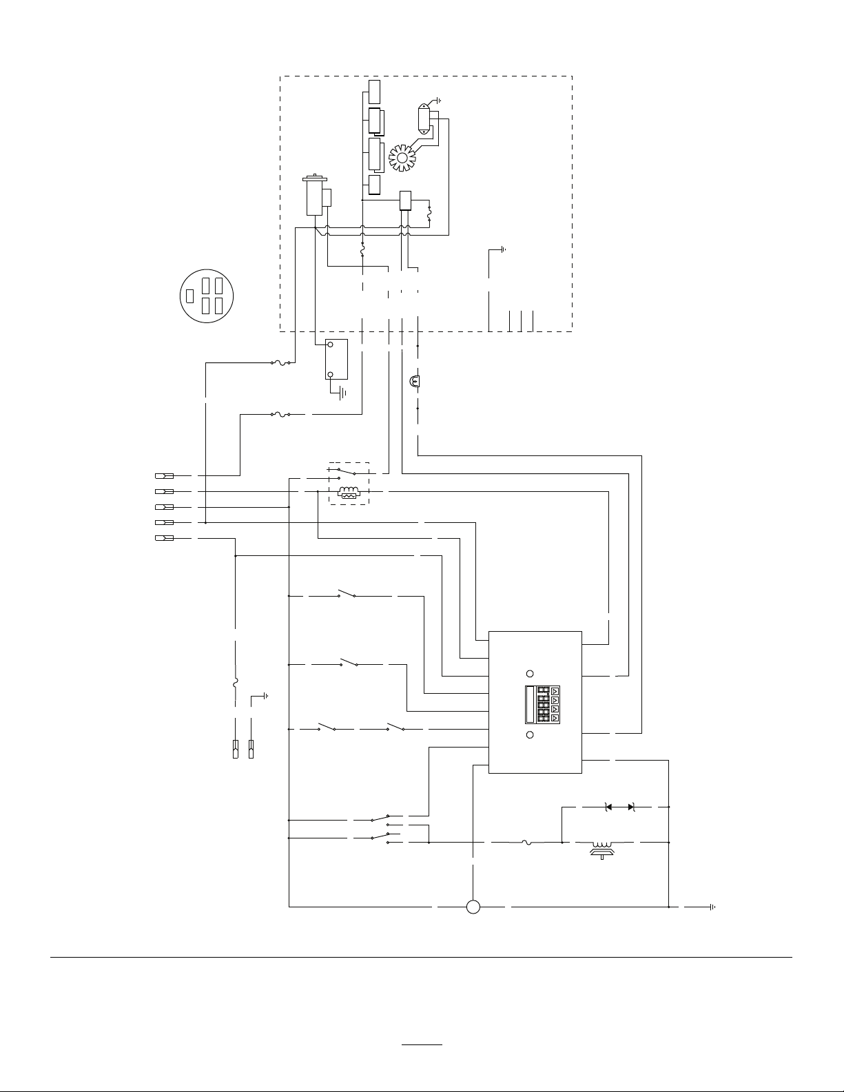
Schematics
BN
BN
BU
BK
Y
W
T
PK
BN
PK
OR
GN
S R
PK PK
PK
LTGR
GY
GY
PK
V
BN V
OR
GN
OR
R BK
PK
BK
GND
PK
BK
BN
BN
BK PK
BK
GND
15A
F4
GY
R
IBA
W
BU
BK
+
S
-
FUEL SENDER
10A
F3
(BRAKE)
SW6
PKOR R
PTO
CLUTCH
BU
1
2
5
4
7
8
(PTO SWITCH)
SW2
LAMP
(SEAT)
SW7
2
3
5
4
1
K2
(START RELAY)
TVS DIODE
U2
(NEUT_R)
SW5
GND-S/D
MIL GND
ECU PWR
S
TART
(NEUT_L)
SW4
12
B+
10
KEY_S
9
KEY_A
4
SEAT
11
BRAKE
2
NEUTRAL
3
PTO
5
FUEL
1
START_RELAY
7
MAGNETO
6
FUEL_SOLENOID
8
GROUND
HOUR METER
R A
I
A
4
7
1 3
A
3
SW1
B
B
C
B
8
24 5
(IGNITION)
C
B
D
KEY SW
OPTIONAL
ACCESSORIES
E
A
587
2
4
S
Ignition switch terminal locations
viewed from back
OFF = no connections
ON = BRIA
S
TART = BRIS
BK = BLACK
BN = BROWN
BU = BLUE
GN = GREEN
GY = GREY
L
T GR = LIGHT GREEN
OR = ORANGE
PK = PINK
R = RED
T = TAN
V = VIOLET
W = WHITE
R
V
YW/RD
OR/WH
OR/BK
BRIGGS OIL GUARD
STARTER
BK
BK/RD
GN
NCNC
NC
NC
NC
FUEL
PUMP
ECU
GND
AC
AC
O2
SENSOR
INJECTORS
IGNITION
COILS
V
V
F3
25A
F1
25A
6
2
1
5
+
-
(BRAKE
OFF)
(PTO OFF)
(OPERATOR
NOT IN SEAT)
(LH HYDRO
IN DRIVE)
(RH HYDRO
IN DRIVE)
163
15A
20A
ElectricalSchematic(Rev .A)
g361552
73

HydraulicSchematic(Rev .A)
74
g008623

CaliforniaProposition65WarningInformation
Whatisthiswarning?
Youmayseeaproductforsalethathasawarninglabellikethefollowing:
WARNING:CancerandReproductiveHarm—www.p65Warnings.ca.gov.
WhatisProp65?
Prop65appliestoanycompanyoperatinginCalifornia,sellingproductsinCalifornia,ormanufacturingproductsthatmaybesoldinorbroughtinto
California.ItmandatesthattheGovernorofCaliforniamaintainandpublishalistofchemicalsknowntocausecancer,birthdefects,and/orother
reproductiveharm.Thelist,whichisupdatedannually,includeshundredsofchemicalsfoundinmanyeverydayitems.ThepurposeofProp65isto
informthepublicaboutexposuretothesechemicals.
Prop65doesnotbanthesaleofproductscontainingthesechemicalsbutinsteadrequireswarningsonanyproduct,productpackaging,orliteraturewith
theproduct.Moreover,aProp65warningdoesnotmeanthataproductisinviolationofanyproductsafetystandardsorrequirements.Infact,the
CaliforniagovernmenthasclariedthataProp65warning“isnotthesameasaregulatorydecisionthataproductis‘safe’or‘unsafe.’”Manyofthese
chemicalshavebeenusedineverydayproductsforyearswithoutdocumentedharm.Formoreinformation,gotohttps://oag.ca.gov/prop65/faqs-view-all
AProp65warningmeansthatacompanyhaseither(1)evaluatedtheexposureandhasconcludedthatitexceedsthe“nosignicantrisklevel”;or(2)
haschosentoprovideawarningbasedonitsunderstandingaboutthepresenceofalistedchemicalwithoutattemptingtoevaluatetheexposure.
Doesthislawapplyeverywhere?
Prop65warningsarerequiredunderCalifornialawonly .ThesewarningsareseenthroughoutCaliforniainawiderangeofsettings,includingbutnot
limitedtorestaurants,grocerystores,hotels,schools,andhospitals,andonawidevarietyofproducts.Additionally ,someonlineandmailorder
retailersprovideProp65warningsontheirwebsitesorincatalogs.
.
HowdotheCaliforniawarningscomparetofederallimits?
Prop65standardsareoftenmorestringentthanfederalandinternationalstandards.TherearevarioussubstancesthatrequireaProp65warning
atlevelsthatarefarlowerthanfederalactionlimits.Forexample,theProp65standardforwarningsforleadis0.5μg/day,whichiswellbelow
thefederalandinternationalstandards.
Whydon’tallsimilarproductscarrythewarning?
•ProductssoldinCaliforniarequireProp65labellingwhilesimilarproductssoldelsewheredonot.
•AcompanyinvolvedinaProp65lawsuitreachingasettlementmayberequiredtouseProp65warningsforitsproducts,butothercompanies
makingsimilarproductsmayhavenosuchrequirement.
•TheenforcementofProp65isinconsistent.
•CompaniesmayelectnottoprovidewarningsbecausetheyconcludethattheyarenotrequiredtodosounderProp65;alackofwarningsfora
productdoesnotmeanthattheproductisfreeoflistedchemicalsatsimilarlevels.
WhydoesToroincludethiswarning?
Torohaschosentoprovideconsumerswithasmuchinformationaspossiblesothattheycanmakeinformeddecisionsabouttheproductstheybuyand
use.T oroprovideswarningsincertaincasesbasedonitsknowledgeofthepresenceofoneormorelistedchemicalswithoutevaluatingthelevelof
exposure,asnotallthelistedchemicalsprovideexposurelimitrequirements.WhiletheexposurefromT oroproductsmaybenegligibleorwellwithinthe
“nosignicantrisk”range,outofanabundanceofcaution,T orohaselectedtoprovidetheProp65warnings.Moreover,ifT orodoesnotprovidethese
warnings,itcouldbesuedbytheStateofCaliforniaorbyprivatepartiesseekingtoenforceProp65andsubjecttosubstantialpenalties.
RevA

 Loading...