


FormNo.3435-863RevB
ZMaster
®
Professional6000
SeriesRidingMower
with60inor72inTURBOFORCE
DischargeMower
ModelNo.72960—SerialNo.406397883andUp
ModelNo.72961—SerialNo.400000000andUp
ModelNo.72967—SerialNo.400000000andUp
ModelNo.72968—SerialNo.400000000andUp
®
Side
Registeratwww.T oro.com.
OriginalInstructions(EN)
*3435-863*B
ItisaviolationofCaliforniaPublicResourceCode
Section4442or4443touseoroperatetheengineon
anyforest-covered,brush-covered,orgrass-covered
landunlesstheengineisequippedwithaspark
arrester,asdenedinSection4442,maintainedin
effectiveworkingorderortheengineisconstructed,
equipped,andmaintainedforthepreventionofre.
Theenclosedengineowner'smanualissupplied
forinformationregardingtheUSEnvironmental
ProtectionAgency(EPA)andtheCaliforniaEmission
ControlRegulationofemissionsystems,maintenance,
andwarranty.Replacementsmaybeorderedthrough
theenginemanufacturer.
GrossorNetTorque:Thegrossornettorque
ofthisenginewaslaboratoryratedbytheengine
manufacturerinaccordancewiththeSocietyof
AutomotiveEngineers(SAE)J1940orJ2723.As
conguredtomeetsafety,emission,andoperating
requirements,theactualenginetorqueonthisclass
ofmowerwillbesignicantlylower.Pleasereferto
theenginemanufacturer’sinformationincludedwith
themachine.
Readthisinformationcarefullytolearnhowtooperate
andmaintainyourproductproperlyandtoavoid
injuryandproductdamage.Youareresponsiblefor
operatingtheproductproperlyandsafely .
Visitwww.Toro.comforproductsafetyandoperation
trainingmaterials,accessoryinformation,helpnding
adealer,ortoregisteryourproduct.
Wheneveryouneedservice,genuineToroparts,or
additionalinformation,contactanAuthorizedService
DealerorToroCustomerServiceandhavethemodel
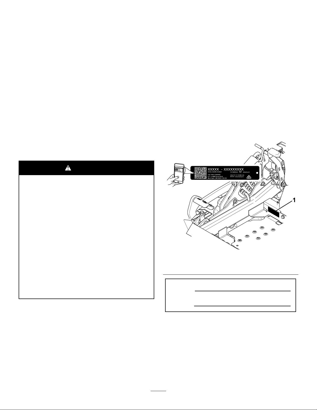
andserialnumbersofyourproductready.Figure1
identiesthelocationofthemodelandserialnumbers
ontheproduct.Writethenumbersinthespace
provided.
Important:Withyourmobiledevice,youcan
scantheQRcode(ifequipped)ontheserial
numberdecaltoaccesswarranty,parts,andother
productinformation.
WARNING
CALIFORNIA
Proposition65Warning
Theengineexhaustfromthisproduct
containschemicalsknowntotheStateof
Californiatocausecancer,birthdefects,
orotherreproductiveharm.
Batteryposts,terminals,andrelated
accessoriescontainleadandlead
compounds,chemicalsknownto
theStateofCaliforniatocause
cancerandreproductiveharm.Wash
handsafterhandling.
Useofthisproductmaycauseexposure
tochemicalsknowntotheStateof
Californiatocausecancer,birthdefects,
orotherreproductiveharm.
g233771
Figure1
1.Modelandserialnumberlocation
ModelNo.
SerialNo.
Introduction
Thisrotary-blade,ridinglawnmowerisintendedtobe
usedbyprofessional,hiredoperators.Itisdesigned
primarilyforcuttinggrassonwell-maintainedlawns
onresidentialorcommercialproperties.Usingthis
productforpurposesotherthanitsintendedusecould
provedangeroustoyouandbystanders.
©2019—TheToro®Company
8111LyndaleAvenueSouth
Bloomington,MN55420
Thismanualuses2wordstohighlightinformation.
Importantcallsattentiontospecialmechanical
informationandNoteemphasizesgeneralinformation
worthyofspecialattention.
2
Contactusatwww.Toro.com.
PrintedintheUSA
AllRightsReserved

Contents
Safety.......................................................................4
SafetyAlertSymbol............................................4
GeneralSafety...................................................4
SlopeIndicator...................................................5
SafetyandInstructionalDecals..........................6
ProductOverview...................................................13
Controls...........................................................13
Specications..................................................15
Attachments/Accessories.................................15
BeforeOperation.................................................16
BeforeOperationSafety...................................16
AddingFuel......................................................17
PerformingDailyMaintenance..........................18
BreakinginaNewMachine..............................18
UsingtheRollover-ProtectionSystem
(ROPS).........................................................18
UsingtheSafety-InterlockSystem....................19
PositioningtheSeat..........................................20
UnlatchingtheSeat..........................................20
ChangingtheSeatSuspension.........................21
AdjustingtheRear-ShockAssemblies..............21
DuringOperation.................................................22
DuringOperationSafety...................................22
EnteringtheOperator’sPosition.......................25
OperatingtheParkingBrake.............................25
OperatingtheMowerBlade-ControlSwitch
(PTO)............................................................25
OperatingtheThrottle.......................................26
StartingtheEngine...........................................27
ShuttingOfftheEngine.....................................27
UsingtheMotion-ControlLevers.......................28
DrivingtheMachine..........................................28
UsingtheSideDischarge.................................29
AdjustingtheHeightofCut...............................30
AdjustingtheAnti-ScalpRollers........................31
AdjustingtheFlowBafeKnob.........................31
PositioningtheFlowBafe................................32
OperatingTips.................................................33
AfterOperation....................................................33
AfterOperationSafety......................................33
UsingtheFuel-ShutoffValve.............................34
UsingtheDrive-Wheel-ReleaseValves............34
TransportingtheMachine.................................35
Maintenance...........................................................37
MaintenanceSafety..........................................37
RecommendedMaintenanceSchedule(s)...........38
Lubrication..........................................................39
GreasingtheMachine.......................................39
LubricatingtheMowerDeck-LiftPivots.............39
GreasingtheMowerDeck................................40
GreasingtheCasterPivots...............................40
GreasingtheCaster-WheelHubs.....................41
EngineMaintenance...........................................42
EngineSafety...................................................42
ServicingtheAirCleaner..................................42
ServicingtheEngineOil....................................43
ServicingtheSparkPlug(s)..............................45
FuelSystemMaintenance...................................46
ReplacingtheFuelFilter...................................46
ServicingtheFuelT ank.....................................47
ElectricalSystemMaintenance...........................47
ElectricalSystemSafety...................................47
ServicingtheBattery.........................................47
ServicingtheFuses..........................................49
DriveSystemMaintenance..................................50
CheckingtheSeatBelt.....................................50
CheckingtheRoll-BarKnobs............................50
AdjustingtheTracking......................................51
CheckingtheTirePressure...............................51
CheckingtheWheelLugNuts...........................52
CheckingtheWheel-HubSlottedNut................52
AdjustingtheCaster-PivotBearing...................52
RemovingtheClutchShim...............................53
CoolingSystemMaintenance..............................54
CleaningtheEngineScreenandEngine-Oil
Cooler...........................................................54
CleaningtheEngine-CoolingFinsand
Shrouds........................................................55
CheckingandCleaningtheHydraulic-Unit
Shrouds........................................................55
BrakeMaintenance.............................................56
AdjustingtheParkingBrake..............................56
BeltMaintenance................................................57
InspectingtheBelts..........................................57
ReplacingtheMowerBelt.................................57
ReplacingtheHydraulicPump-Drive
Belt................................................................58
ControlsSystemMaintenance.............................59
AdjustingtheControl-HandlePosition..............59
AdjustingtheMotion-ControlLinkage...............60
AdjustingtheMotion-ControlDamper...............61
AdjustingtheMotion-ControlNeutral-Lock
Pivot..............................................................61
HydraulicSystemMaintenance...........................62
HydraulicSystemSafety...................................62
Hydraulic-FluidSpecications..........................62
CheckingtheHydraulicFluid............................62
ChangingtheHydraulicFluidand
Filters............................................................63
MowerDeckMaintenance....................................64
BladeSafety.....................................................64
ServicingtheCuttingBlades.............................64
LevelingtheMowerDeck..................................67
RemovingtheMowerDeck...............................69
ReplacingtheGrassDeector..........................71
Cleaning..............................................................71
CleaningundertheMowerDeck.......................71
CleaningtheSuspensionSystem.....................71
DisposingofWaste...........................................71
Storage...................................................................72
StorageSafety..................................................72
CleaningandStorage.......................................72
Troubleshooting......................................................73
Schematics.............................................................75
3

Safety
Thismachinehasbeendesignedinaccordancewith
ANSIstandardB71.4-2017.
SafetyAlertSymbol
ThisSafetyAlertSymbol(Figure2)isusedbothin
thismanualandonthemachinetoidentifyimportant
safetymessageswhichmustbefollowedtoavoid
accidents.
Thissymbolmeans:ATTENTION!BECOMEALERT!
YOURSAFETYISINVOL VED!
Figure2
SafetyAlertSymbol
GeneralSafety
Thismachineiscapableofamputatinghandsandfeet
andofthrowingobjects.T orodesignedandtested
thislawnmowertoofferreasonablysafeservice;
however,failuretocomplywithsafetyinstructions
mayresultininjuryordeath.
•Read,understand,andfollowallinstructionsand
warningsintheOperator’sManualandother
trainingmaterial,onthemachine,engine,and
attachments.Alloperatorsandmechanicsshould
betrained.Iftheoperator(s)ormechanic(s)can
notreadthismanual,itistheowner’sresponsibility
toexplainthismaterialtothem;otherlanguages
maybeavailableonourwebsite.
•Onlyallowtrained,responsible,andphysically
capableoperatorsthatarefamiliarwiththesafe
g000502
operation,operatorcontrols,andsafetysignsand
instructionstooperatethemachine.Neverlet
childrenoruntrainedpeopleoperateorservicethe
equipment.Localregulationsmayrestricttheage
oftheoperator.
Thesafetyalertsymbolappearsaboveinformation
whichalertsyoutounsafeactionsorsituationsand
willbefollowedbythewordDANGER,WARNING,or
CAUTION.
DANGER:Indicatesanimminentlyhazardous
situationwhich,ifnotavoided,Willresultindeathor
seriousinjury.
WARNING:Indicatesapotentiallyhazardoussituation
which,ifnotavoided,Couldresultindeathorserious
injury.
CAUTION:Indicatesapotentiallyhazardoussituation
which,ifnotavoided,Mayresultinminorormoderate
injury.
Thismanualusestwootherwordstohighlight
information.Importantcallsattentiontospecial
mechanicalinformationandNoteemphasizesgeneral
informationworthyofspecialattention.
•Alwayskeeptherollbarinthefullyraisedand
lockedpositionandusetheseatbelt.
•Donotoperatethemachineneardrop-offs,
ditches,embankments,water,orotherhazards,or
onslopesgreaterthan15degrees.
•Donotputyourhandsorfeetnearmoving
componentsofthemachine.
•Neveroperatethemachinewithdamagedguards,
shields,orcovers.Alwayshavesafetyshields,
guards,switchesandotherdevicesinplaceandin
properworkingcondition.
•Stopthemachine,shutofftheengine,andremove
thekeybeforeservicing,fueling,orunclogging
themachine.
4

SlopeIndicator
Figure3
Youmaycopythispageforpersonaluse.
1.Themaximumslopeyoucanoperatethemachineonis15degrees.Usetheslopecharttodeterminethedegreeofslopeof
hillsbeforeoperating.Donotoperatethismachineonaslopegreaterthan15degrees.Foldalongtheappropriateline
tomatchtherecommendedslope.
2.Alignthisedgewithaverticalsurface,atree,building,fencepole,etc.
3.Exampleofhowtocompareslopewithfoldededge
5
g011841

SafetyandInstructionalDecals
Safetydecalsandinstructionsareeasilyvisibletotheoperatorandarelocatednearanyarea
ofpotentialdanger.Replaceanydecalthatisdamagedormissing.
BatterySymbols
Someorallofthesesymbolsareonyourbattery .
decalbatterysymbols
1.Explosionhazard6.Keepbystandersaway
fromthebattery .
2.Nore,opename,or
smoking
7.Weareyeprotection;
explosivegasescan
causeblindnessandother
injuries.
3.Causticliquid/chemical
burnhazard
8.Batteryacidcancause
blindnessorsevereburns.
4.Weareyeprotection.9.Flusheyesimmediately
withwaterandgetmedical
helpfast.
5.ReadtheOperator's
Manual.
10.Containslead;donot
discard
Manufacturer'sMark
1.Thismarkindicatesthatthebladeisidentiedasapart
fromtheoriginalmachinemanufacturer.
decal99-8936
99-8936
1.Machinespeed4.Neutral
2.Fast5.Reverse
3.Slow
decaloemmarkt
decal106-2655
106-2655
1.Warning—donottouchorapproachmovingbelts;remove
thekeyandreadtheinstructionsbeforeservicingor
performingmaintenance.
decal58-6520
58-6520
1.Grease
106-5517
decal106-5517
1.Warning—donottouchthehotsurface.
6

decal107-3069
107-3069
1.Warning–thereisnorolloverprotectionwhentherollbaris
down.
2.Toavoidinjuryordeathfromarolloveraccident,keepthe
rollbarintheraisedandlockedpositionandweartheseat
belt.Lowertherollbaronlywhenabsolutelynecessary;do
notweartheseatbeltwhentherollbarisdown.
3.ReadtheOperator'sManual;driveslowlyandcarefully.
decal110-2067
110-2067
decal112-9028
112-9028
1.Warning—stayawayfrommovingparts;keepallguards
andshieldsinplace.
decal114-4466
114-4466
1.Main(25A)3.Charge(25A)
2.PTO(10A)4.Auxiliary(15A)
MachineswithMyRide™Only
107-3969
1.Warning—readtheOperator'sManual.
2.Crushinghazard,mower—engagetheparkingbrake,shut
offtheengine,andremovethekeybeforeworkingunder
themower .
decal107-3969
decal115-9625
115-9625
1.Parking
brake—disengaged
2.Parkingbrake—engaged
7
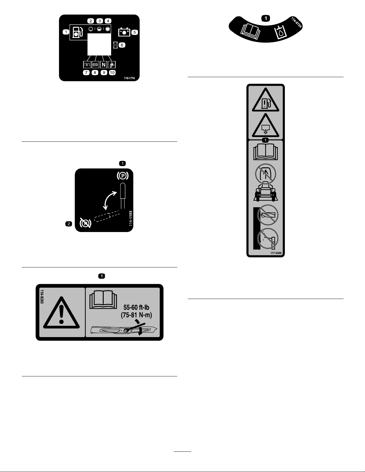
116-1716
1.Fuel6.Hourmeter
2.Empty
3.Half
4.Full9.Neutral
5.Battery
10.Operatorpresenceswitch
MachineswithoutMyRide™Only
decal116-8726
116-8726
1.ReadtheOperator’sManualfortherecommendedhydraulic
uid.
decal116-1716
7.PTO
8.Parkingbrake
116-5988
1.Parkingbrake—engaged2.Parking
brake—disengaged
116-8283
1.Warning—readtheOperator'sManualforinstructionson
torquingthebladebolt/nutto75to81N∙m(55to60ft-lb).
decal116-5988
decal117-0346
117-0346
1.Fuelleakhazard—readtheOperator'sManual;donot
attempttoremovetherollbar;donotweld,drill,ormodify
therollbarinanyway.
decal116-8283
8

117-3848
1.Thrownobjecthazard—keepbystandersaway.
2.Thrownobjecthazard,raiseddeector—donotoperate
withoutthedeector ,dischargecover,orgrasscollection
systeminplace.
3.Cutting/dismembermenthazardofhandorfoot,mower
blade—stayawayfrommovingparts;keepallguardsand
shieldsinplace.
decal117-3848
120-5898
decal120-5898
1.Choke4.Slow
2.Fast
5.Powertake-off(PTO),
Bladecontrolswitch
3.Continuousvariable
setting
decal126-2055
126-2055
1.Wheellugnut—torqueto129N∙m(95ft-lb).
2.Wheelhubnut—torqueto319N∙m(235ft-lb).
3.ReadtheOperator’sManualbeforeperforming
maintenance;checkthetorqueaftertherst100hoursand
every500hoursafter.
120-5897
1.Choke4.Slow
2.Fast
3.Continuousvariable
setting
5.Powertake-off(PTO),
Bladecontrolswitch
decal120-5897
decal126-4398
126-4398
1.ReadtheOperator’s
Manual.
2.Lock
3.Unlock
9
126-4659
1.Warning—hotpulley;allowtocool.
decal126-4659
1.ReadtheOperator's
Manual.
2.Heightofcut
127-0326
3.Removethekeyand
readtheOperator's
Manualbeforeperforming
maintenance.
decal127-0326
1.ReadtheOperator's
131-1180
3.Baggingsetting
decal131-1180
Manual.
2.Short,lightgrass;dry
conditions
4.Tall,densegrass;wet
conditions
MachineswithMyRide™Only
1.Camlock2.Camunlock
10
decal132-5063
132-5063

decal133-8062
133-8062
decal136-5508
136-5508
1.Beltrouting
125-9383
1.Checkhydraulicuidevery50operatinghours.3.Checkthetirepressureevery50operatinghours.
2.ReadtheOperator’sManualforinformationonlubricating
themachine.
4.ReadtheOperator’sManualbeforeservicingorperforming
maintenance.
11
decal125-9383

MachineswithMyRide™Only
decal132-5067
132-5067
132-0871
Note:Thismachinecomplieswiththeindustrystandardstabilitytestinthestaticlateralandlongitudinaltestswiththemaximum
recommendedslopeindicatedonthedecal.ReviewtheinstructionsforoperatingthemachineonslopesintheOperator’sManualas
wellastheconditionsinwhichyouwouldoperatethemachinetodeterminewhetheryoucanoperatethemachineintheconditionson
thatdayandatthatsite.Changesintheterraincanresultinachangeinslopeoperationforthemachine.
1.Warning—readtheOperator’sManual;alloperatorsshould
betrainedbeforeoperatingthemachine;wearhearing
protection.
2.Cutting/dismembermenthazardofhand—stayawayfrom
movingparts;keepallguardsandshieldsinplace.
3.Thrownobjecthazard—keepbystandersaway.
4.Tippinghazard—donotusedualrampswhenloadingontoa
trailer;use1rampwideenoughforthemachine;usearamp
withaslopelessthan15°;backuptheramp(inreverse)and
driveforwardofftheramp.
5.Runoverhazard—donotcarrypassengers;lookbehindyou
whenmovinginreverse.
6.Tippinghazard—donotusethemachineneardrop-offsor
onslopesgreaterthan15°;onlyoperateacrossslopesless
than15°.
decal132-0871
12
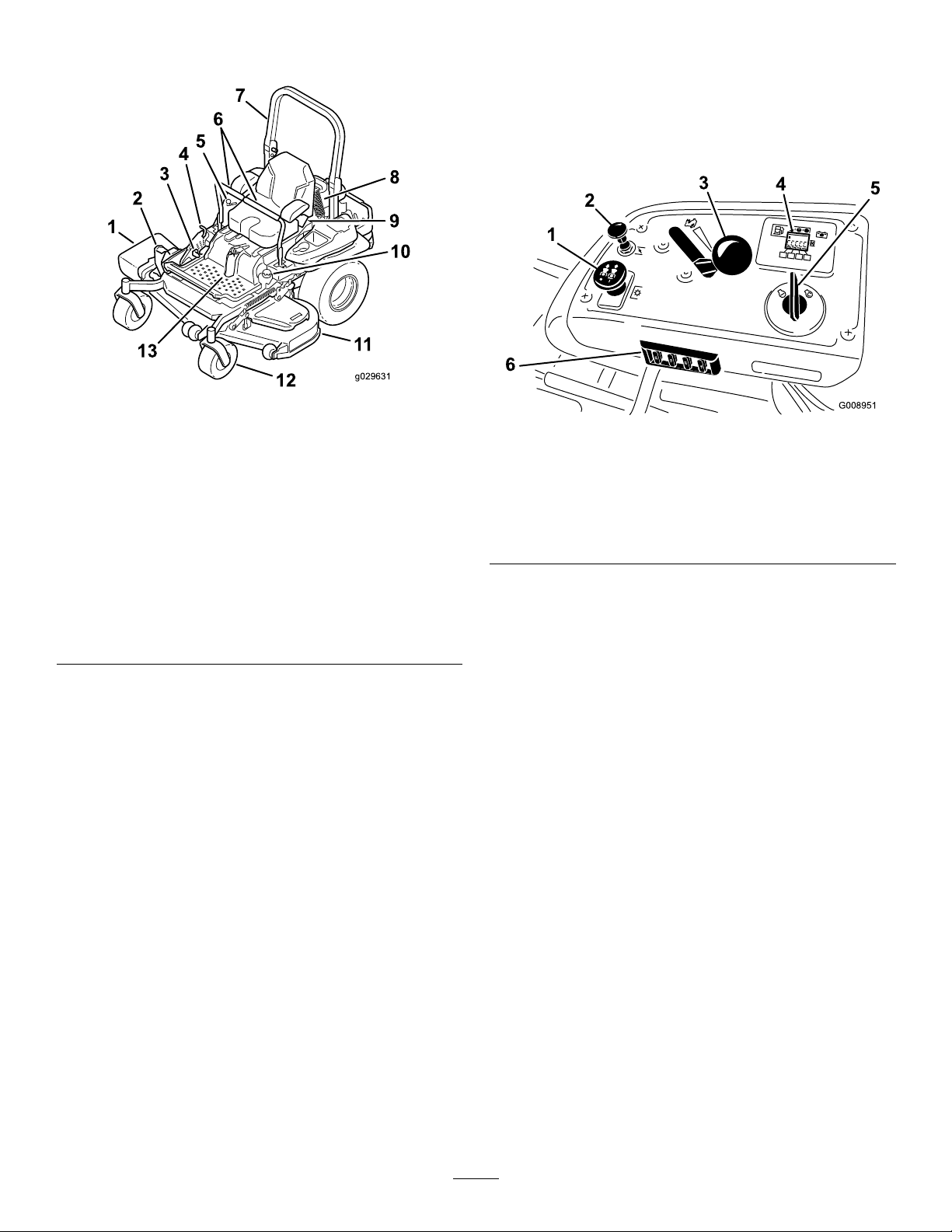
ProductOverview
Figure4
1.Side-dischargedeector
2.Height-of-cutdeck-lift
pedal
3.Parking-brakelever10.Fuelcap
4.Transportlock11.Mowerdeck
5.Controls12.Casterwheel
6.Motion-controllevers13.Front-shockassembly
7.Rollbar
8.Rear-shockassembly
9.Seatbelt
(machineswithMyRide™
only)
(machineswithMyRide™
only)
Controls
Becomefamiliarwithallthecontrolsbeforeyoustart
theengineandoperatethemachine.
ControlPanel
g029631
g008951
Figure5
1.Blade-controlswitch
(powertakeoff)
2.Chokecontrol
3.Throttlecontrol6.Fuses
KeySwitch
Thekeyswitch,usedtostartandshutofftheengine,
has3positions:OFF,RUN,andST ART.Referto
StartingtheEngine(page27).
4.Hour
meter/Safety-interlock
display
5.Keyswitch
ThrottleControl
Thethrottlecontrolstheenginespeed,andithasa
continuous-variablesettingfromtheSLOWtoFAST
position(Figure5).
ChokeControl
Usethechokecontroltostartacoldengine.
Blade-ControlSwitch(Power
Takeoff)
Theblade-controlswitch,representedbya
power-takeoff(PTO)symbol,engagesand
disengagespowertothemowerblades(Figure5).
HourMeter
Thehourmeterrecordsthenumberofhoursthe
enginehasoperated.Itoperateswhentheengine
13

isrunning.Usethesetimesforschedulingregular
maintenance(Figure6).
Figure6
1.Fuelgauge(bars)4.Safety-interlocksymbols
2.Batterylight
3.Hourmeter
5.Lowfuelindicatorlight
FuelGauge
themachine(Figure25).Alwayspositionthe
motion-controlleversintotheNEUTRAL-LOCKposition
whenyoustopthemachineorleaveitunattended.
Parking-BrakeLever
Wheneveryoushutofftheengine,engagetheparking
braketopreventaccidentalmovementofthemachine.
Fuel-ShutoffValve
Closethefuel-shutoffvalvewhentransportingor
storingthemachine;refertoUsingtheFuel-Shutoff
Valve(page34).
g008950
Thefuelgaugeislocatedwithinthehourmeter,and
thebarslightupwhenthekeyswitchisintheON
position(Figure6).
Theindicatorlightappearswhenthefuellevelislow
(approximately1gallonremaininginthefueltank).
Safety-InterlockIndicators
Therearesymbolsonthehourmeterthatindicate
withablacktrianglethattheinterlockcomponentis
positionedcorrectly(Figure6).
Battery-IndicatorLight
IfyouturnthekeyswitchtotheONpositionfora
fewseconds,thebatteryvoltagedisplaysinthearea
wherethehoursarenormallydisplayed.
Thebatterylightturnsonwhenthekeyswitchis
turnedonandwhenthechargeisbelowthecorrect
operatinglevel(Figure6).
Motion-ControlLevers
Usethemotion-controlleverstodrivethemachine
forward,reverse,andturneitherdirection(Figure4).
Neutral-LockPosition
Movethemotion-controlleversoutwardfromthe
centertotheNEUTRAL-LOCKpositionwhenexiting
14

Specications
Note:Specicationsanddesignaresubjecttochangewithoutnotice.
Width
Withoutthedeck
Deectorup
Deectordown
Length
Rollbarup
Rollbardown
Height
Rollbarup
Rollbardown
122cm(48-inch)Deck132cm(52-inch)Deck152cm(60-inch)Deck
116cm116cm135cm150cm
(46inches)(46inches)(53inches)(59inches)
137cm146cm157cm187cm
(54inches)(58inches)(62inches)(74inches)
161cm172cm192cm222cm
(64inches)(68inches)(76inches)(88inches)
122cm(48-inch)Deck132cm(52-inch)Deck152cm(60-inch)Deck
201cm201cm21 1cm219cm
(79inches)(79inches)(83inches)(86inches)
206cm206cm215cm223cm
(81inches)(81inches)(85inches)(88inches)
122cm(48-inch)Deck132cm(52-inch)Deck152cm(60-inch)Deck
179cm179cm179cm179cm
(71inches)(71inches)(71inches)(71inches)
119cm119cm119cm119cm
(47inches)(47inches)(47inches)(47inches)
72-inchDeck
72-inchDeck
72-inchDeck
Weight
ModelWeight
74960
74961
75967
75968
576kg(1,269lb)
612kg(1,349lb)
576kg(1,269lb)
612kg(1,349lb)
Attachments/Accessories
AselectionofToroapprovedattachmentsandaccessoriesisavailableforusewiththemachinetoenhance
andexpanditscapabilities.ContactyourAuthorizedServiceDealerorauthorizedT orodistributororgoto
www.T oro.comforalistofallapprovedattachmentsandaccessories.
Toensureoptimumperformanceandcontinuedsafetycerticationofthemachine,useonlygenuineT oro
replacementpartsandaccessories.Replacementpartsandaccessoriesmadebyothermanufacturerscouldbe
dangerous,andsuchusecouldvoidtheproductwarranty .
15

Operation
Note:Determinetheleftandrightsidesofthe
machinefromthenormaloperatingposition.
BeforeOperation
BeforeOperationSafety
GeneralSafety
•Evaluatetheterraintodeterminewhataccessories
andattachmentsareneededtoproperlyand
safelyperformthejob.Onlyuseaccessoriesand
attachmentsapprovedbyToro.
FuelSafety
Useextremecarewhenhandlingfuel.
DANGER
Incertainconditionsgasolineisextremely
ammableandvaporsareexplosive.
Areorexplosionfromgasolinecanburn
you,others,andcausepropertydamage.
•Fillthefueltankoutdoorsonlevelground,
inanopenarea,whentheengineiscold.
Wipeupanygasolinethatspills.
•Neverrellthefueltankordrainthe
machineindoorsorinsideanenclosed
trailer.
•Inspecttheareawheretheequipmentistobe
usedandremoveallrocks,toys,sticks,wires,
bones,andotherforeignobjects.Thesecan
bethrownorinterferewiththeoperationofthe
machineandmaycausepersonalinjurytothe
operatororbystanders.
•Wearappropriatepersonalprotectiveequipment
suchassafetyglasses,substantialslip-resistant
footwear,andhearingprotection.Tiebacklong
hairandavoidlooseclothingandloosejewelry
whichmaygettangledinmovingparts.
CAUTION
Thismachineproducessoundlevelsin
excessof85dBAattheoperator’searand
cancausehearinglossthroughextended
periodsofexposure.
Wearhearingprotectionwhenoperating
thismachine.
•Checkthattheoperatorpresencecontrols,
safetyswitches,andshieldsareattachedand
functioningproperly.Donotoperateunlessthey
arefunctioningproperly.
•DoNotllthefueltankcompletelyfull.
Fillthefueltanktothebottomoftheller
neck.Theemptyspaceinthetankallows
gasolinetoexpand.Overllingmayresult
infuelleakageordamagetotheengineor
emissionsystem.
•Neversmokewhenhandlinggasoline,and
stayawayfromanopenameorwhere
gasolinefumesmaybeignitedbyspark.
•Storegasolineinanapprovedcontainer
andkeepitoutofthereachofchildren.
•Addfuelbeforestartingtheengine.Never
removethecapofthefueltankoraddfuel
whenengineisrunningorwhentheengine
ishot.
•Iffuelisspilled,DoNotattempttostart
theengine.Moveawayfromtheareaof
thespillandavoidcreatinganysourceof
ignitionuntilfuelvaporshavedissipated.
•DoNotoperatewithoutentireexhaust
systeminplaceandinproperworking
condition.
•Donotoperatethemowerwhenpeople,especially
children,orpetsareinthearea.Stopthemachine
andattachment(s)ifanyoneentersthearea.
•Donotoperatethemachinewithouttheentire
grasscollectionsystem,dischargedeector,
orothersafetydevicesinplaceandinproper
workingcondition.Grasscatchercomponents
aresubjecttowear,damageanddeterioration,
whichcouldexposemovingpartsorallowobjects
tobethrown.Frequentlycheckforwornor
deterioratingcomponentsandreplacethemwith
themanufacturer’srecommendedpartswhen
necessary.
16

DANGER
Incertainconditionsduringfueling,static
electricitycanbereleasedcausingaspark
whichcanignitegasolinevapors.Areor
explosionfromgasolinecanburnyouand
othersandcausepropertydamage.
•Alwaysplacegasolinecontainersonthe
groundawayfromyourvehiclebefore
lling.
•DoNotllgasolinecontainersinsidea
vehicleoronatruckortrailerbedbecause
interiorcarpetsorplastictruckbedliners
mayinsulatethecontainerandslowthe
lossofanystaticcharge.
•Whenpractical,removegas-powered
equipmentfromthetruckortrailerand
refueltheequipmentwithitswheelsonthe
ground.
•Ifthisisnotpossible,thenrefuelsuch
equipmentonatruckortrailerfroma
portablecontainer,ratherthanfroma
gasolinedispensernozzle.
•Ifagasolinedispensernozzlemustbe
used,keepthenozzleincontactwiththe
rimofthefueltankorcontaineropeningat
alltimesuntilfuelingiscomplete.DoNot
useanozzlelockopendevice.
WARNING
Gasolineisharmfulorfatalifswallowed.
Long-termexposuretovaporshascaused
cancerinlaboratoryanimals.Failuretouse
cautionmaycauseseriousinjuryorillness.
Tohelppreventres:
•Keepengineandengineareafreefrom
accumulationofgrass,leaves,excessivegrease
oroil,andotherdebriswhichcanaccumulatein
theseareas.
•Cleanupoilandfuelspillsandremovefuelsoaked
debris.
•Allowthemachinetocoolbeforestoringthe
machineinanyenclosure.DoNotstorenear
ameoranyenclosedareawhereopenpilotlights
orheatappliancesarepresent.
AddingFuel
RecommendedFuel
•Forbestresults,useonlyclean,fresh(lessthan
30daysold),unleadedgasolinewithanoctane
ratingof87orhigher((R+M)/2ratingmethod).
•Ethanol:Gasolinewithupto10%ethanol
(gasohol)or15%MTBE(methyltertiarybutyl
ether)byvolumeisacceptable.Ethanoland
MTBEarenotthesame.Gasolinewith15%
ethanol(E15)byvolumeisnotapprovedforuse.
Neverusegasolinethatcontainsmorethan
10%ethanolbyvolume,suchasE15(contains
15%ethanol),E20(contains20%ethanol),orE85
(containsupto85%ethanol).Usingunapproved
gasolinemaycauseperformanceproblemsand/or
enginedamagewhichmaynotbecoveredunder
warranty.
•Donotusegasolinecontainingmethanol.
•Donotstorefueleitherinthefueltankorfuel
containersoverthewinterunlessyouuseafuel
stabilizer.
•Donotaddoiltogasoline.
•Avoidprolongedbreathingofvapors.
•Keepfaceawayfromnozzleandgas
tank/containeropening.
•Keepawayfromeyesandskin.
•Neversiphonbymouth.
CAUTION
Fueltankventislocatedinsidetheroll
bartube.Removingormodifyingtheroll
barcouldresultinfuelleakageandviolate
emissionsregulations.
•DoNotremoverollbar.
•DoNotweld,drill,ormodifyrollbarinany
way.
UsingStabilizer/Conditioner
Useafuelstabilizer/conditionerinthemachineto
providethefollowingbenets:
•Keepsfuelfreshlongerwhenusedasdirectedby
thefuel-stabilizermanufacturer
•Cleanstheenginewhileitruns
•Eliminatesgum-likevarnishbuildupinthefuel
system,whichcauseshardstarting
Important:Donotusefueladditives
containingmethanolorethanol.
Addthecorrectamountoffuelstabilizer/conditioner
tothefuel.
Note:Afuelstabilizer/conditionerismost
effectivewhenmixedwithfreshfuel.T ominimize
17

thechanceofvarnishdepositsinthefuelsystem,
usefuelstabilizeratalltimes.
PerformingDaily
Maintenance
FillingtheFuelTank
1.Parkthemachineonalevelsurface.
2.Engagetheparkingbrake.
3.Shutofftheengineandremovethekey.
4.Cleanaroundthefuel-tankcap.
5.Fillthefueltanktothebottomofthellerneck
(Figure7).
Note:Donotllthefueltankcompletelyfull.
Theemptyspaceinthetankallowsthefuelto
expand.
Beforestartingthemachineeachday ,performthe
EachUse/DailyprocedureslistedinMaintenance
(page37).
BreakinginaNewMachine
Newenginestaketimetodevelopfullpower.Mower
decksanddrivesystemshavehigherfrictionwhen
new,placingadditionalloadontheengine.Allow
40to50hoursofbreak-intimefornewmachinesto
developfullpowerandbestperformance.
Usingthe
Rollover-ProtectionSystem
(ROPS)
WARNING
Toavoidinjuryordeathfromrollover,keep
therollbarinthefullyraised,lockedposition
andusetheseatbelt.
Figure7
Ensurethattheseatissecuredtothe
machine.
WARNING
Thereisnorolloverprotectionwhentheroll
barisinthedownposition.
•Lowertherollbaronlywhenabsolutely
necessary.
•Donotweartheseatbeltwhentherollbar
isinthedownposition.
•Driveslowlyandcarefully.
•Raisetherollbarassoonasclearance
permits.
•Checkcarefullyforoverheadclearances
g027726
(i.e.,branches,doorways,electricalwires)
beforedrivingunderanyobjectsanddo
notcontactthem.
LoweringtheRollBar
Important:Lowertherollbaronlywhen
absolutelynecessary.
1.T olowertherollbar,applyforwardpressureto
theupperpartoftherollbar.
2.Pullbothknobsoutandrotatethem90degrees
sotheyarenotengaged(Figure8).
18

3.Lowertherollbartothedownposition(Figure
8).
UsingtheSafety-Interlock
System
WARNING
Ifthesafety-interlockswitchesare
disconnectedordamaged,themachinecould
operateunexpectedly,causingpersonal
injury.
•Donottamperwiththeinterlockswitches.
•Checktheoperationoftheinterlock
switchesdailyandreplaceanydamaged
switchesbeforeoperatingthemachine.
Understandingthe
Safety-InterlockSystem
Thesafety-interlocksystemisdesignedtopreventthe
enginefromstartingunlessthefollowingoccurs:
•Theparkingbrakeisengaged.
•Theblade-controlswitch(PTO)isdisengaged.
•Themotion-controlleversareintheNEUTRAL-LOCK
position.
Figure8
1.Rollbarintheupright
position
2.ROPSknobinthelatched
position
3.PulltheROPSknobout.6.Rollbarinthefolded
4.RotatetheROPSknob90
degrees.
5.ROPSknobinthe
unlatchedposition
position
RaisingtheRollBar
Important:Alwaysusetheseatbeltwiththeroll
barintheraisedposition.
1.Raisetherollbartotheoperatingpositionand
rotatetheknobsuntiltheymovepartiallyinto
thegrooves(Figure8).
2.Raisetherollbartothefulluprightpositionwhile
pushingontheupperrollbarsothatthepins
snapintopositionwhentheholesalignwiththe
pins(Figure8).
3.Pushontherollbarandensurethatbothpins
areengaged.
Thesafety-interlocksystemalsoisdesignedtoshut
offtheenginewhenthemotion-controlleversare
movedfromtheNEUTRAL-LOCKpositionwiththe
parkingbrakeengagedorifyourisefromtheseat
whenthePTOisengaged.
Thehourmeterhasindicatorstonotifytheuserwhen
g228804
theinterlockcomponentisinthecorrectposition.
Whenthecomponentisinthecorrectposition,an
indicatordisplaysonthescreen.
g009181
Figure9
1.Indicatorsdisplaywhentheinterlockcomponentsareinthe
correctposition
TestingtheSafety-Interlock
System
ServiceInterval:Beforeeachuseordaily
19

Testthesafety-interlocksystembeforeyouusethe
machineeachtime.Ifthesafetysystemdoesnot
operateasdescribedbelow,haveanAuthorized
ServiceDealerrepairthesafetysystemimmediately .
1.Sitontheseat,engagetheparkingbrake,and
movetheblade-controlswitch(PTO)totheON
position.Trystartingtheengine;theengine
shouldnotstart.
2.Sitontheseat,engagetheparkingbrake,and
movetheblade-controlswitch(PTO)totheOFF
position.Moveeithermotion-controlleverout
oftheNEUTRAL-LOCKposition.Trystartingthe
engine;theengineshouldnotstart.Repeatfor
theothercontrollever.
3.Sitontheseat,engagetheparkingbrake,
movetheblade-controlswitch(PTO)totheOFF
position,andmovethemotion-controllevers
totheNEUTRAL-LOCKposition.Nowstartthe
engine.Whiletheengineisrunning,disengage
theparkingbrake,engagetheblade-control
switch(PTO),andriseslightlyfromtheseat;the
engineshouldshutoff.
4.Sitontheseat,engagetheparkingbrake,
movetheblade-controlswitch(PTO)totheOFF
position,andmovethemotion-controllevers
totheNEUTRAL-LOCKposition.Nowstartthe
engine.Whiletheengineisrunning,center
eithermotioncontrolandmove(forwardor
reverse);theengineshouldshutoff.Repeatfor
othermotioncontrol.
PositioningtheSeat
Theseatcanmoveforwardandbackward.Position
theseatwhereyouhavethebestcontrolofthe
machineandaremostcomfortable(Figure10).
g019754
Figure10
UnlatchingtheSeat
MachineswithMyRide™
SuspensionSystem
5.Sitontheseat,disengagetheparkingbrake,
movetheblade-controlswitch(PTO)totheOFF
position,andmovethemotion-controllevers
totheNEUTRAL-LOCKposition.Trystartingthe
engine;theengineshouldnotstart.
g204507
Figure11
20

MachineswithoutMyRide™
SuspensionSystem
Tounlatchtheseat,pushtheseatlatchforward
(Figure12).
Figure12
1.Seatlatch2.Seat
ChangingtheSeat
Suspension
AdjustingtheRear-Shock
Assemblies
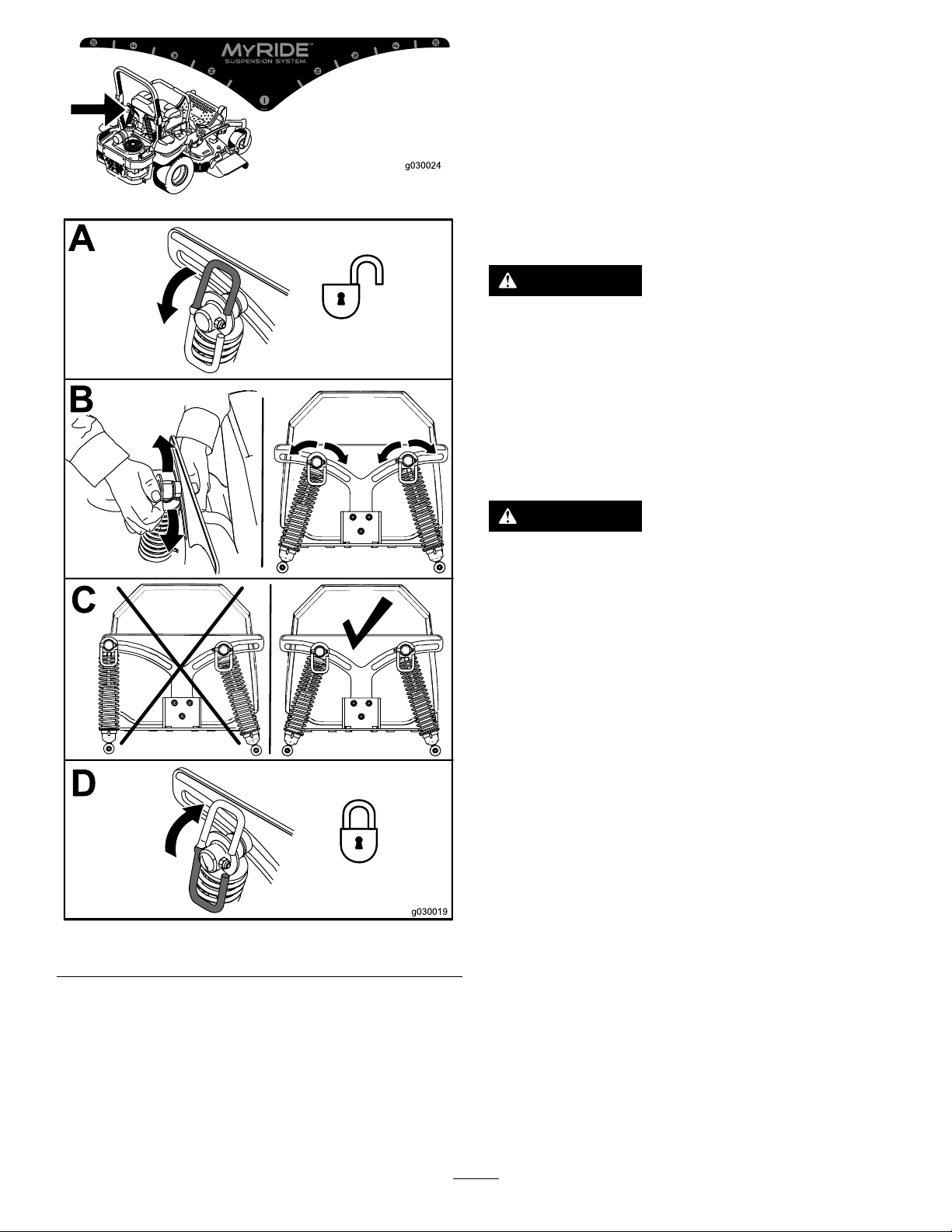
MachineswithMyRide™
SuspensionSystemOnly
TheMyRide™suspensionsystemadjuststoprovide
asmoothandcomfortableride.Youcanadjustthe
rear2-shockassembliestoquicklyandeasilychange
thesuspensionsystem.Positionthesuspension
systemwhereyouaremostcomfortable.
Theslotsfortherear-shockassemblieshave
g008956
detentpositionsforreference.Youcanpositionthe
rear-shockassembliesanywhereintheslot,notjustin
thedetentpositions.Thefollowinggraphicshowsthe
positionforasoftorrmrideandthedifferentdetent
positions(Figure14).
MachineswithoutMyRide™
SuspensionSystemOnly
Theseatisadjustabletoprovideasmoothand
comfortableride.Positiontheseatwhereyouare
mostcomfortable.
Toadjustit,turntheknobinfronteitherdirectionto
providethebestcomfort(Figure13).
Figure13
1.Seat-suspensionknob
g030065
Figure14
1.Firmestposition3.Detentsintheslots
2.Softestposition
Note:Ensurethattheleftandrightrear-shock
assembliesarealwaysadjustedtothesamepositions.
Adjusttherear-shockassemblies(Figure15).
g024881
21
DuringOperation
DuringOperationSafety
GeneralSafety
g030024
Theoperatormustusetheirfullattentionwhen
operatingthemachine.DoNotengageinanyactivity
thatcausesdistractions;otherwise,injuryorproperty
damagemayoccur.
WARNING
Operatingengineparts,especiallythemufer,
becomeextremelyhot.Severeburnscan
occuroncontactanddebris,suchasleaves,
grass,brush,etc.cancatchre.
•Allowengineparts,especiallythemufer,
tocoolbeforetouching.
•Removeaccumulateddebrisfrommufer
andenginearea.
WARNING
Engineexhaustcontainscarbonmonoxide,
whichisanodorlessdeadlypoisonthatcan
killyou.
DoNotrunengineindoorsorinasmall
connedareawheredangerouscarbon
monoxidefumescancollect.
Figure15
•Theowner/usercanpreventandisresponsible
foraccidentsorinjuriesoccurringtohimselfor
herself,otherpeopleorproperty .
•Thismowerwasdesignedforoneoperatoronly .
Donotcarrypassengersandkeepallothersaway
frommachineduringoperation.
•Donotoperatethemachinewhileill,tired,or
undertheinuenceofalcoholordrugs.
•Operateonlyindaylightorgoodarticiallight.
•Lightningcancausesevereinjuryordeath.If
lightningisseenorthunderisheardinthearea,
g030019
DoNotoperatethemachine;seekshelter.
•Useextracarewhileoperatingwithaccessoriesor
attachments,suchasgrasscollectionsystems.
Thesecanchangethestabilityofthemachine
andcausealossofcontrol.Followdirectionsfor
counterweightsifrequired.
•Keepawayfromholes,ruts,bumps,rocks,and
otherhiddenhazards.Usecarewhenapproaching
blindcorners,shrubs,trees,tallgrassorother
objectsthatmayhideobstaclesorobscurevision.
Uneventerraincouldoverturnthemachineor
causetheoperatortolosetheirbalanceorfooting.
22

•Besurealldrivesareinneutralandparkingbrake
isengagedbeforestartingengine.Useseatbelts
withtherollbarintheraisedandlockedposition.
•Starttheenginecarefullyaccordingtoinstructions
withfeetwellawayfromtheblades.
•Neveroperatethemowerwithdamagedguards,
shields,orcovers.Alwayshavesafetyshields,
guards,switchesandotherdevicesinplaceandin
properworkingcondition.
•Keepclearofthedischargeopeningatalltimes.
Nevermowwiththedischargedoorraised,
removedoralteredunlessthereisagrass
collectionsystemormulchkitinplaceandworking
properly.
•Keephandsandfeetawayfrommovingparts.
Ifpossible,DoNotmakeadjustmentswiththe
enginerunning.
WARNING
Hands,feet,hair,clothing,oraccessories
canbecomeentangledinrotatingparts.
Contactwiththerotatingpartscan
causetraumaticamputationorsevere
lacerations.
–DoNotoperatethemachinewithout
guards,shields,andsafetydevicesin
placeandworkingproperly.
–Keephands,feet,hair,jewelry,or
clothingawayfromrotatingparts.
–Beforeclearingblockages.
–Wheneveryouleavethemower.DoNotleave
arunningmachineunattended.
•Stopengine,waitforallmovingpartstostop:
–Beforerefueling.
–Beforedumpingthegrasscatcher.
–Beforemakingheightadjustments.
•Tragicaccidentscanoccuriftheoperatorisnot
alerttothepresenceofchildren.Childrenare
oftenattractedtothemachineandthemowing
activity.Neverassumethatchildrenwillremain
whereyoulastsawthem.
–Keepchildrenoutofthemowingareaand
underthewatchfulcareofanotherresponsible
adult,nottheoperator.
–Bealertandturnthemachineoffifchildren
enterthearea.
–Beforeandwhilebackingorchangingdirection,
lookbehind,down,andside-to-sideforsmall
children.
–Neverallowchildrentooperatethemachine.
–DoNotcarrychildren,evenwiththeblades
shutoff.Childrencouldfalloffandbeseriously
injuredorinterferewiththesafeoperationof
themachine.Childrenthathavebeengiven
ridesinthepastcouldsuddenlyappearinthe
workingareaforanotherrideandberunover
orbackedoverbythemachine.
•Neverraisethedeckwithbladesrunning.
•Beawareofthemowerdischargepathanddirect
dischargeawayfromothers.Avoiddischarging
materialagainstawallorobstructionasthe
materialmayricochetbacktowardtheoperator.
Stoptheblades,slowdown,andusecautionwhen
crossingsurfacesotherthangrassandwhen
transportingthemowertoandfromtheareatobe
mowed.
•Bealert,slowdownandusecautionwhen
makingturns.Lookbehindandtothesidebefore
changingdirections.DoNotmowinreverse
unlessabsolutelynecessary.
•DoNotchangetheenginegovernorsettingor
overspeedtheengine.
•Parkthemachineonlevelground.Stopengine,
waitforallmovingpartstostop,andremovethe
sparkplugwire(s).
–Beforechecking,cleaningorworkingonthe
mower.
–Afterstrikingaforeignobjectorabnormal
vibrationoccurs(inspectthemowerfor
damageandmakerepairsbeforerestarting
andoperatingthemower).
SlopeSafety
•Slopesareamajorfactorrelatedtolossofcontrol
androlloveraccidents,whichcanresultinsevere
injuryordeath.Theoperatorisresponsiblefor
safeslopeoperation.Operatingthemachineon
anysloperequiresextracaution.Beforeusingthe
machineonaslope,theoperatormust:
–Reviewandunderstandtheslopeinstructions
inthemanualandonthemachine.
–Useanangleindicatortodeterminethe
approximateslopeangleofthearea.
–Neveroperateonslopesgreaterthan15
degrees.
–Evaluatethesiteconditionsofthedayto
determineiftheslopeissafeformachine
operation.Usecommonsenseandgood
judgmentwhenperformingthisevaluation.
Changesintheterrain,suchasmoisture,can
quicklyaffecttheoperationofthemachineon
aslope.
•Identifyhazardsatthebaseoftheslope.Do
Notoperatethemachineneardropoffs,ditches,
embankments,waterorotherhazards.The
23

machinecouldsuddenlyrolloverifawheelgoes
overtheedgeortheedgecollapses.Keepasafe
distance(twicethewidthofthemachine)between
themachineandanyhazard.Useawalkbehind
machineorahandtrimmertomowthegrassin
theseareas.
Figure16
1.SafeZone-Usethemowerhereonslopeslessthan15
degrees
2.DangerZone-Useawalk-behindmowerand/orhand
trimmeronslopesgreaterthan15degrees
3.Water
4.W=widthofthemachine
5.Keepasafedistance(twicethewidthofthemachine)
betweenthemachineandanyhazard.
operatingonslopescancausethemachineto
becomeunstable.
RolloverProtectionSystem
(ROPS)Safety
ARolloverProtectionSystem(rollbar)isinstalledon
themachine.
WARNING
Thereisnorolloverprotectionwhentheroll
barisdown.Wheelsdroppingoveredges,
ditches,steepbanks,orwatercancause
rollovers,whichmayresultinseriousinjury,
deathordrowning.
•DoNotremovetheROPS.
•Keeptherollbarintheraisedandlocked
positionanduseseatbelt.
•Lowertherollbaronlywhenabsolutely
g221745
necessary.
•DoNotwearseatbeltwhentherollbaris
down.
•Driveslowlyandcarefully.
•Raisetherollbarassoonasclearance
permits.
•Becertainthattheseatbeltcanbereleased
quicklyintheeventofanemergency.
•Avoidstarting,stoppingorturningthemachineon
slopes.Avoidmakingsuddenchangesinspeedor
direction;turnslowlyandgradually.
•DoNotoperateamachineunderanyconditions
wheretraction,steeringorstabilityisinquestion.
Beawarethatoperatingthemachineonwet
grass,acrossslopesordownhillmaycausethe
machinetolosetraction.Lossoftractiontothe
drivewheelsmayresultinslidingandalossof
brakingandsteering.Themachinecanslideeven
ifthedrivewheelsarestopped.
•Removeormarkobstaclessuchasditches,holes,
ruts,bumps,rocksorotherhiddenhazards.T all
grasscanhideobstacles.Uneventerraincould
overturnthemachine.
•Useextracarewhileoperatingwithaccessoriesor
attachments,suchasgrasscollectionsystems.
Thesecanchangethestabilityofthemachine
andcausealossofcontrol.Followdirectionsfor
counterweights.
•Ifpossible,keepthedeckloweredtotheground
whileoperatingonslopes.Raisingthedeckwhile
•Checkcarefullyforoverheadclearances(i.e.
branches,doorways,andelectricalwires)before
drivingunderanyobjectsandDoNotcontact
them.
•Intheeventofarollover,taketheunittoan
AuthorizedServiceDealertohavetheROPS
inspected.
•ReplaceadamagedROPS.DoNotrepairor
revise.
•Anyaccessories,alterations,orattachments
addedtotheROPSmustbeapprovedbyT oro.
24

EnteringtheOperator’s
Position
Usethemowerdeckasasteptogetintothe
operator’sposition(Figure17).
Figure17
1.Stephere.
DisengagingtheParkingBrake
g027335
Figure19
OperatingtheMower
Blade-ControlSwitch(PTO)
g029797
Theblade-controlswitch(PTO)startsandstopsthe
mowerbladesandanypoweredattachments.
OperatingtheParking
Brake
Alwaysengagetheparkingbrakewhenyoustopthe
machineorleaveitunattended.
EngagingtheParkingBrake
Parkthemachineonalevelsurface.
Figure18
EngagingtheBlade-Control
Switch(PTO)
Note:Engagingtheblade-controlswitch(PTO)with
thethrottlepositionathalforlesscausesexcessive
weartothedrivebelts.
g008945
Figure20
DisengagingtheBlade-Control
Switch(PTO)
g027334
g009174
Figure21
25

OperatingtheThrottle
YoucanmovethethrottlecontrolbetweenFASTand
SLOWpositions(Figure22).
AlwaysusetheFASTpositionwhenengagingthePTO.
Figure22
g008946
26

StartingtheEngine
Important:Donotengagestarterformorethan5
secondsatatime.Iftheenginefailstostart,wait
15secondsbetweenattempts.Failuretofollow
theseinstructionscanburnoutthestartermotor.
Note:Youmayneedmultipleattemptstostartthe
enginethersttimeafteraddingfueltoanemptyfuel
system.
ShuttingOfftheEngine
CAUTION
Childrenorbystandersmaybeinjuredifthey
moveorattempttooperatethemachinewhile
itisunattended.
Alwaysremovethekeyandengagethe
parkingbrakewhenleavingthemachine
unattended.
Figure23
g032328
g027337
Figure24
Important:Makesurethatthefuel-shutoffvalve
isclosedbeforetransportingorstoringthe
machine,asfuelleakagemayoccur.Engagethe
parkingbrakebeforetransporting.Makesurethat
youremovethekeyasthefuelpumpmayrunand
causethebatterytolosecharge.
27

UsingtheMotion-Control
WARNING
Levers
Themachinecanspinveryrapidly.You
maylosecontrolofthemachineandcause
personalinjuryordamagetothemachine.
•Usecautionwhenmakingturns.
•Slowthemachinedownbeforemaking
sharpturns.
DrivingForward
Note:Theengineshutsoffwhenyoumovethe
traction-controlwiththeparkingbrakeengaged.
Tostopthemachine,pullthemotion-controllevers
totheNEUTRALposition.
1.Disengagetheparkingbrake;referto
DisengagingtheParkingBrake(page25).
2.Movetheleverstothecenter,unlockedposition.
3.T ogoforward,slowlypushthemotion-control
leversforward(Figure26).
Figure25
1.Motion-control
lever—NEUTRAL-LOCK
position
2.Center,unlockedposition5.Frontofmachine
3.Forward
4.Backward
DrivingtheMachine
Thedrivewheelsturnindependently,poweredby
hydraulicmotorsoneachaxle.Youcanturn1side
inreversewhileyouturntheotherforward,causing
themachinetospinratherthanturn.Thisgreatly
improvesthemachinemaneuverabilitybutmay
requiresometimeforyoutoadapttohowitmoves.
Thethrottlecontrolregulatestheenginespeedas
measuredinrpm(revolutionsperminute).Place
thethrottlecontrolintheFASTpositionforbest
performance.Alwaysoperateinthefullthrottle
positionwhenmowing.
g004532
g008952
Figure26
DrivingBackward
1.Movetheleverstothecenter,unlockedposition.
2.T ogobackward,slowlypullthemotion-control
leversrearward(Figure27).
28

Figure27
UsingtheSideDischarge
Themowerhasahingedgrassdeectorthat
dispersesclippingstothesideanddowntowardthe
turf.
DANGER
Withoutagrassdeector,dischargecover,or
acompletegrass-catcherassemblymounted
inplace,youandothersareexposedtoblade
contactandthrowndebris.Contactwith
rotatingmowerblade(s)andthrowndebris
willcauseinjuryordeath.
•Neverremovethegrassdeectorfromthe
mowerdeckbecausethegrassdeector
routesmaterialdowntowardtheturf.Ifthe
g008953
grassdeectoriseverdamaged,replaceit
immediately.
•Neverputyourhandsorfeetunderthe
mowerdeck.
•Nevertrytoclearthedischargearea
ormowerbladesunlessyoumovethe
blade-controlswitch(PTO)totheOFF
position,rotatethekeyswitchtotheOFF
position,andremovethekeyfromthekey
switch.
•Makesurethatthegrassdeectorisinthe
downposition.
29

AdjustingtheHeightofCut
UsingtheTransportLock
Thetransportlockhas2positions,andisusedwith
thedeck-liftpedal.ThereisaLOCKpositionand
anUNLOCKpositionforthetransportpositionofthe
mowerdeck(Figure28).
AdjustingtheHeight-of-CutPin
Theheight-of-cutisadjustedfrom25to140mm(1
to5-1/2inches)in6mm(1/4inch)incrementsby
relocatingtheclevispinintodifferentholelocations.
1.Movethetransportlocktothelockposition.
2.Pushonthedeck-liftpedalwithyourfoot,and
raisethemowerdecktothetransportposition
(alsothe140mm(5-1/2inch)cuttingheight
position)asshowninFigure29.
3.T oadjust,rotatethepin90degreesandremove
thepinfromtheheight-of-cutbracket(Figure
29).
4.Selectaholeintheheight-of-cutbracket
correspondingtotheheight-of-cutdesired,and
insertthepin(Figure29).
5.Pushonthedecklift,pullbackonthetransport
lock,andslowlylowerthemowerdeck.
Figure28
Transport-LockPositions
1.Transportlockknob3.UNLOCKposition—The
2.LOCKposition—The
mowerdecklocksintothe
transportposition.
mowerdeckdoesnotlock
intothetransportposition.
g027343
Figure29
1.Deck-liftpedal
2.Cut-of-heightpin
g229103
30
3.Transportlock

AdjustingtheAnti-Scalp
Rollers
Wheneveryouchangetheheight-of-cut,adjustthe
heightoftheanti-scalprollers.
1.Parkthemachineonalevelsurface,disengage
theblade-controlswitch,andengagetheparking
brake.
2.Shutofftheengine,removethekey ,andwait
forallmovingpartstostopbeforeleavingthe
operatingposition.
3.Adjusttheanti-scalprollersasshowninFigure
30,Figure31,andFigure32.
Figure30
1.Anti-scalproller4.Flangenut
2.Spacer
3.Bushing
5.Bolt
g029957
Figure32
1.Anti-scalproller4.Flangenut
2.Spacer
3.Bushing
5.Bolt
AdjustingtheFlowBafe
Knob
Thisprocedureappliesonlytomachineswiththe
owbafeknob.Certainmodelshavenutsandbolts
g029955
insteadoftheowbafeknobthatyoucanadjustthe
sameway.
Youcanadjustthemowerdischargeowfordifferent
typesofmowingconditions.Positiontheknoband
bafetogivethebestqualityofcut.
1.Parkthemachineonalevelsurface,disengage
theblade-controlswitch,andengagetheparking
brake.
Figure31
1.Anti-scalproller3.Flangenut
2.Bushing4.Bolt
2.Shutofftheengine,removethekey ,andwait
forallmovingpartstostopbeforeleavingthe
operatingposition.
3.Loosentheknob.
4.Slidetheknobtothedesiredposition.
5.Tightentheknob.
g029956
31

PositioningtheFlowBafe
Thefollowingguresarerecommendationsonly.
Adjustmentsvarybygrasstype,moisturecontent,
andtheheightofthegrass.
Note:Iftheenginepowerdrawsdownandthe
mowergroundspeedisthesame,openthebafe.
PositionA
Thisisthefully-rearposition.Thesuggestedusefor
thispositionisasfollows:
•Short,lightgrassmowingconditions
•Dryconditions
•Smallergrassclippings
•Propelsgrassclippingsfartherawayfromthe
mower
g295811
Figure34
PositionC
PositionB
Thisisthefully-forwardposition.Thesuggesteduse
forthispositionisasfollows:
•Tall,densegrassmowingconditions
•Wetconditions
•Lowerstheengine-powerconsumption
•Allowsincreasedgroundspeedinheavyconditions
g295810
Figure33
Usethispositionwhenbagging.Alwaysalignitwith
thebloweropening.
g295812
Figure35
32

OperatingTips
UsingtheFastThrottleSetting
dropontoyourlawn.Toavoidthis,moveontoa
previouslycutareawiththebladesengagedoryou
candisengagethemowerdeckwhilemovingforward.
Forbestmowingandmaximumaircirculation,operate
theengineattheFASTposition.Airisrequiredto
thoroughlycutgrassclippings,sodonotsetthe
height-of-cutsolowastototallysurroundthemower
deckinuncutgrass.Alwaystrytohave1sideofthe
mowerdeckfreefromuncutgrass,whichallowsair
tobedrawnintothemowerdeck.
CuttingaLawnfortheFirstTime
Cutgrassslightlylongerthannormaltoensurethat
thecuttingheightofthemowerdeckdoesnotscalp
anyunevenground.However,thecuttingheight
usedinthepastisgenerallythebestonetouse.
Whencuttinggrasslongerthan15cm(6inches)tall,
youmaywanttocutthelawntwicetoensurean
acceptablequalityofcut.
CuttingaThirdoftheGrassBlade
Itisbesttocutonlyaboutathirdofthegrassblade.
Cuttingmorethanthatisnotrecommendedunless
grassissparse,oritislatefallwhengrassgrows
moreslowly.
KeepingtheUndersideofthe
MowerDeckClean
Cleanclippingsanddirtfromtheundersideofthe
mowerdeckaftereachuse.Ifgrassanddirtbuildup
insidethemowerdeck,cuttingqualitywilleventually
becomeunsatisfactory.
MaintainingtheBlade(s)
Maintainasharpbladethroughoutthecuttingseason
becauseasharpbladecutscleanlywithouttearingor
shreddingthegrassblades.Tearingandshredding
turnsgrassbrownattheedges,whichslowsgrowth
andincreasesthechanceofdisease.Checkthe
mowerbladesaftereachuseforsharpness,and
foranywearordamage.Filedownanynicksand
sharpenthebladesasnecessary .Ifabladeis
damagedorworn,replaceitimmediatelywitha
genuineT ororeplacementblade.
AfterOperation
AlternatingtheMowingDirection
Alternatethemowingdirectiontokeepthegrass
standingstraight.Thisalsohelpsdisperseclippings,
whichenhancesdecompositionandfertilization.
MowingatCorrectIntervals
Grassgrowsatdifferentratesatdifferenttimesof
theyear.Tomaintainthesamecuttingheight,mow
moreofteninearlyspring.Asthegrassgrowthrate
slowsinmidsummer,mowlessfrequently.Ifyou
cannotmowforanextendedperiod,rstmowata
highcuttingheight,thenmowagain2dayslaterata
lowerheightsetting.
UsingaSlowerCuttingSpeed
Toimprovecutquality,useaslowergroundspeed
incertainconditions.
AvoidingCuttingTooLow
Whenmowinguneventurf,raisethecuttingheight
toavoidscalpingtheturf.
AfterOperationSafety
GeneralSafety
•Parkmachineonlevelground,disengagedrives,
setparkingbrake,stopengine,removekeyor
disconnectsparkplugwire.Waitforallmovement
tostopandallowthemachinetocoolbefore
adjusting,cleaning,repairing,orstoring.Never
allowuntrainedpersonneltoservicemachine.
•CleanthemachineasstatedintheMaintenance
section.Keepengineandengineareafreefrom
accumulationofgrass,leaves,excessivegrease
oroil,andotherdebriswhichcanaccumulate
intheseareas.Thesematerialscanbecome
combustibleandmayresultinare.
•Frequentlycheckforwornordeteriorating
componentsthatcouldcreateahazard.Tighten
loosehardware.
StoppingtheMachine
Ifyoumuststoptheforwardmotionofthemachine
whilemowing,aclumpofgrassclippingsmay
33

UsingtheFuel-Shutoff
Usingthe
Valve
Thefuel-shutoffvalveislocatedundertheseat.Move
theseatforwardtoaccessit.
Closethefuel-shutoffvalvefortransport,maintenance,
andstorage.
Ensurethatthefuel-shutoffvalveisopenwhen
startingtheengine.
Figure36
1.ONposition2.OFFposition
Drive-Wheel-Release
Valves
WARNING
Handsmaybecomeentangledintherotating
drivecomponentsbelowtheenginedeck,
whichcouldresultinseriousinjury.
Shutofftheengine,removethekey,andallow
allmovingpartstostopbeforeaccessingthe
drive-wheel-releasevalves.
WARNING
Theengineandhydraulic-driveunitscan
becomeveryhot.Touchingahotengineor
hydraulic-driveunitscancausesevereburns.
Allowtheengineandhydraulic-driveunits
tocoolcompletelybeforeaccessingthe
drive-wheel-releasevalves.
g008948
Thedrive-wheel-releasevalvesarelocatedinthe
backofeachhydraulic-driveunit,undertheseat.
Note:Makesurethatthereleasevalvesareinthe
fullyhorizontalpositionwhenoperatingthemachine;
otherwise,severedamagetothehydraulicsystem
canoccur.
1.Parkthemachineonalevelsurface,disengage
theblade-controlswitch,andengagetheparking
brake.
2.Shutofftheengine,removethekey ,andwait
forallmovingpartstostopbeforeleavingthe
operatingposition.
3.Rotatetherelease-valveleversverticallytopush
themachine(Figure37).
Note:Thisallowshydraulicuidtobypassthe
pump,enablingthewheelstoturn.
4.Disengagetheparkingbrakebeforepushing
themachine.
34

Figure37
1.Verticaltopushthe
machine
5.Rotatethereleasevalvelevershorizontallyto
runthemachine(Figure37).
2.Horizontaltorunthe
machine
SelectingaTrailer
WARNING
Loadingamachineontoatrailerortruck
increasesthepossibilityoftip-overandcould
causeseriousinjuryordeath(Figure38).
•Useonlyafull-widthramp;donotuse
individualrampsforeachsideofthe
machine.
•Donotexceeda15-degreeanglebetween
therampandthegroundorbetweenthe
g015123
rampandthetrailerortruck.
•Ensurethatthelengthoftherampisat
least4timesaslongastheheightofthe
trailerortruckbedtotheground.This
ensuresthattherampangledoesnot
exceed15degreesonatground.
TransportingtheMachine
Useaheavy-dutytrailerortrucktotransportthe
machine.Useafull-widthramp.Ensurethatthetrailer
ortruckhasallthenecessarybrakes,lighting,and
markingasrequiredbylaw.Pleasecarefullyreadall
thesafetyinstructions.Knowingthisinformationcould
helpyouorbystandersavoidinjury.Refertoyour
localordinancesfortrailerandtie-downrequirements.
WARNING
Drivingonthestreetorroadwaywithout
turnsignals,lights,reectivemarkings,ora
slow-moving-vehicleemblemisdangerous
andcanleadtoaccidents,causingpersonal
injury.
Donotdrivethemachineonapublicstreet
orroadway.
35

1.Ifusingatrailer,connectittothetowingvehicle
andconnectthesafetychains.
2.Ifapplicable,connectthetrailerbrakesand
lights.
3.Lowertheramp,ensuringthattheangle
betweentherampandthegrounddoesnot
exceed15degrees(Figure38).
4.Backthemachineuptheramp(Figure39).
Figure39
g028043
1.Full-widthrampinstowed
position
2.Sideviewoffull-width
rampinloadingposition
3.Notgreaterthan
15degrees
LoadingtheMachine
Figure38
4.Rampisatleast4times
aslongastheheightof
thetrailerortruckbedto
theground
5.H=heightofthetraileror
truckbedtotheground
6.Trailer
1.Backthemachineupthe
ramp.
2.Drivethemachineforward
downtheramp.
5.Shutofftheengine,removethekey,andengage
theparkingbrake.
6.Tiedownthemachinenearthefrontcaster
wheelsandtherearbumperwithstraps,chains,
cable,orropes(Figure40).Refertolocal
regulationsfortie-downrequirements.
g027996
WARNING
Loadingamachineontoatrailerortruck
increasesthepossibilityoftip-overandcould
causeseriousinjuryordeath.
•Useextremecautionwhenoperatinga
machineonaramp.
•Backthemachineuptherampanddriveit
forwarddowntheramp.
•Avoidsuddenaccelerationordeceleration
whiledrivingthemachineonarampas
thiscouldcausealossofcontrolora
tip-oversituation.
g027338
Figure40
1.Tie-downloops
UnloadingtheMachine
1.Lowertheramp,ensuringthattheangle
betweentherampandthegrounddoesnot
exceed15degrees(Figure38).
2.Drivethemachineforwarddowntheramp
(Figure39).
36

Maintenance
MaintenanceSafety
WARNING
Whilemaintenanceoradjustmentsarebeing
made,someonecouldstarttheengine.
Accidentalstartingoftheenginecould
seriouslyinjureyouorotherbystanders.
Removethekeyfromtheignitionswitch,
engageparkingbrake,andpullthewire(s)
offthesparkplug(s)beforeyoudoany
maintenance.Alsopushthewire(s)asideso
itdoesnotaccidentallycontactthespark
plug(s).
WARNING
Theenginecanbecomeveryhot.Touchinga
hotenginecancausesevereburns.
Allowtheenginetocoolcompletelybefore
serviceormakingrepairsaroundtheengine
area.
•Parkmachineonlevelground,disengagedrives,
setparkingbrake,stopengine,removekeyor
disconnectsparkplugwire.Waitforallmovement
tostopandallowthemachinetocoolbefore
adjusting,cleaningorrepairing.Neverallow
untrainedpersonneltoservicemachine.
•Disconnectbatteryorremovesparkplugwire
beforemakinganyrepairs.Disconnectthe
negativeterminalrstandthepositivelast.
Reconnectpositiverstandnegativelast.
•Keepthemachine,guards,shieldsandall
safetydevicesinplaceandinsafeworking
condition.Frequentlycheckforwornor
deterioratingcomponentsandreplacethemwith
themanufacturer’srecommendedpartswhen
necessary.
WARNING
Removalormodicationoforiginal
equipment,partsand/oraccessories
mayalterthewarranty ,controllability,
andsafetyofthemachine.Unauthorized
modicationstotheoriginalequipmentor
failuretouseoriginalToropartscouldlead
toseriousinjuryordeath.Unauthorized
changestothemachine,engine,fuelor
ventingsystem,mayviolateapplicable
safetystandardssuchas:ANSI,OSHAand
NFPAand/orgovernmentregulationssuch
asEP AandCARB.
WARNING
Hydraulicuidescapingunderpressure
canpenetrateskinandcauseinjury.Fluid
accidentallyinjectedintotheskinmustbe
surgicallyremovedwithinafewhoursby
adoctorfamiliarwiththisformofinjuryor
gangrenemayresult.
–Ifequipped,makesureallhydraulic
uidhosesandlinesareingood
conditionandallhydraulicconnections
andttingsaretightbeforeapplying
pressuretohydraulicsystem.
–Keepbodyandhandsawayfrom
pinholeleaksornozzlesthatejecthigh
pressurehydraulicuid.
–Usecardboardorpaper,notyourhands,
tondhydraulicleaks.
–Safelyrelieveallpressureinthe
hydraulicsystembyplacingthemotion
controlleversinneutralandshuttingoff
theenginebeforeperforminganywork
onthehydraulicsystem.
WARNING
Fuelsystemcomponentsareunder
highpressure.Theuseofimproper
componentscanresultinsystemfailure,
gasolineleakageandpossibleexplosion.
Useonlyapprovedfuellinesandfuellters
forhighpressuresystems.
•Usecarewhencheckingblades.Wrapthe
blade(s)orweargloves,andusecautionwhen
servicingthem.Onlyreplacedamagedblades.
Neverstraightenorweldthem.
37

•Usejackstandstosupportthemachineand/or
componentswhenrequired.
CAUTION
Raisingthemachineforserviceor
maintenancerelyingsolelyonmechanical
orhydraulicjackscouldbedangerous.
Themechanicalorhydraulicjacksmaynot
beenoughsupportormaymalfunction
allowingthemachinetofall,whichcould
causeinjury.
Donotrelysolelyonmechanicalor
hydraulicjacksforsupport.Useadequate
jackstandsorequivalentsupport.
•Carefullyreleasepressurefromcomponentswith
storedenergy.
RecommendedMaintenanceSchedule(s)
•Keephandsandfeetawayfrommovingparts.
Ifpossible,DoNotmakeadjustmentswiththe
enginerunning.Ifthemaintenanceoradjustment
procedurerequiretheenginetoberunningand
componentsmoving,useextremecaution.
WARNING
Contactwithmovingpartsorhotsurfaces
maycausepersonalinjury .
Keepyourngers,hands,andclothing
clearofrotatingcomponentsandhot
surfaces.
•Checkallboltsfrequentlytomaintainproper
tightness.
MaintenanceService
Interval
Aftertherst8hours
Aftertherst100hours
Aftertherst250hours
Beforeeachuseordaily
Every50hours
Every100hours
MaintenanceProcedure
•Changetheengineoil.
•Checkthewheellug-nuttorque.
•Checkthewheel-hubslotted-nuttorque.
•Adjusttheparkingbrake.
•Changethehydraulicltersandhydraulicuid.
•Checkthesafety-interlocksystem.
•Checktheengine-oillevel.
•Checktheseatbelt.
•Checktherollbarknobs.
•Cleantheenginescreenandtheoilcooler.
•Checkandcleanthehydraulic-unitshrouds.
•Inspecttheblades.
•Cleanthemowerdeck.
•Cleanthesuspensionsystem.
•Checkthetirepressure
•Inspectthebeltsforcracksandwear.
•Checkthehydraulic-uidlevel.
•Lubricatethemowerdeck-liftpivots.
•Changetheengineoil(moreoftenindirtyordustyconditions).
•ForKawasakiengines—replaceorcleanandgapthesparkplug.
•Checkandcleanengine-coolingnsandshrouds.
Every200hours
Every250hours
Every400hours
•Changetheengine-oillter(moreoftenindirtyordustyconditions).
•Replacetheprimaryairlter(moreoftenindirtyordustyconditions).
•Checkthesafetyairlter(moreoftenindirtyordustyconditions).
•Aftertheinitialchange—changethehydraulic-systemltersanduidwhenusing
Mobil115W50uid.(Changeitmoreoftenunderdirtyordustyconditions)
•Greasethecasterpivots(moreoftenindirtyordustyconditions).
38

MaintenanceService
Every500hours
Interval
MaintenanceProcedure
•Replacethesafetyairlter(moreoftenindirtyordustyconditions).
•Replacethefuellter(moreoftenindusty ,dirtyconditions).
•Checkthewheellug-nuttorque.
•Checkthewheel-hubslotted-nuttorque.
•Adjustthecaster-pivotbearing.
•Adjusttheparkingbrake.
•Aftertheinitialchange—changethehydraulic-systemltersanduidwhenusing
Toro®HYPR-OIL™500uid.(Changeitmoreoftenunderdirtyordustyconditions)
Monthly
Yearly
Yearlyorbeforestorage
•Checkthebatterycharge.
•Greasethepump-belt-idlerarm.
•Repackthecaster-wheelbearings(moreoftenindirtyordustyconditions).
•Greasingthecaster-wheelhubs.
•Paintchippedsurfaces.
•Checkallmaintenanceprocedureslistedabovebeforestorage.
Important:Refertoyourengineowner'smanualforadditionalmaintenanceprocedures.
CAUTION
Ifyouleavethekeyintheswitch,someonecouldaccidentlystarttheengineandseriously
injureyouorotherbystanders.
Shutofftheengineandremovethekeyfromtheswitchbeforeyouperformanymaintenance.
Lubrication
LubricatingtheMower
Deck-LiftPivots
GreasingtheMachine
Greasethemachinemoreoftenindirtyordusty
conditions.
GreaseType:No.2lithiumormolybdenumgrease
ServiceInterval:Every100hours
Uselightoilorspraylubricanttolubricatethedeck-lift
pivots.
1.Parkthemachineonalevelsurface,disengage
theblade-controlswitch,andengagetheparking
brake.
2.Shutofftheengine,removethekey ,andwait
forallmovingpartstostopbeforeleavingthe
operatingposition.
3.Cleanthegreasettingswitharag.
Note:Scrapeanypaintoffthefrontofthe
tting(s).
4.Connectagreaseguntothetting.
5.Pumpgreaseintothettingsuntilgreasebegins
tooozeoutofthebearings.
6.Wipeupanyexcessgrease.
g017028
Figure41
39

GreasingtheMowerDeck
ServiceInterval:Y early—Greasethepump-belt-idler
arm.
1.Parkthemachineonalevelsurface,disengage
theblade-controlswitch,andengagetheparking
brake.
Note:Keepthedustcapoffuntilgreasingis
done.
6.Removethehexplug.
7.Threadagreasettingintothehole.
8.Pumpgreaseintothettinguntilitoozesout
aroundthetopbearing.
2.Shutofftheengine,removethekey ,andwait
forallmovingpartstostopbeforeleavingthe
operatingposition.
3.Greasethemowerdeckidler-pulleypivotuntil
greasecomesoutthebottom(Figure42).
Figure42
9.Removethegreasettinginthehole.
10.Installthehexpluganddustcap(Figure44).
g027339
Figure44
11.Greasethecaster-wheelbearings(Figure44).
g295792
GreasingtheCasterPivots
4.Greasethedrive-belt-idlerarm(Figure43).
Figure43
5.Removethedustcapandadjustthecaster
pivots.
ServiceInterval:Every400hours/Yearly(whichever
comesrst)(moreoftenindirtyor
dustyconditions).
Yearly—Repackthecaster-wheelbearings
(moreoftenindirtyordustyconditions).
1.Parkthemachineonalevelsurface,disengage
theblade-controlswitch,andengagetheparking
brake.
2.Shutofftheengine,removethekey ,andwait
forallmovingpartstostopbeforeleavingthe
operatingposition.
3.Removethedustcapandadjustthecaster
pivotsandkeepthedustcapoffuntilgreasingis
done;refertoGreasingtheMowerDeck(page
40).
4.Removethehexplug.
g009030
5.Threadagreasettingintothehole.
6.Pumpgreaseintothettinguntilitoozesout
aroundthetopbearing.
7.Removethegreasettingfromthehole.Install
thehexplugandcap.
40

GreasingtheCaster-Wheel
Hubs
ServiceInterval:Yearly
1.Parkthemachineonalevelsurface,disengage
theblade-controlswitch,andengagetheparking
brake.
2.Shutofftheengine,removethekey ,andwait
forallmovingpartstostopbeforeleavingthe
operatingposition.
3.Raisethemowerforaccess.
4.Removethecasterwheelfromthecasterforks.
5.Removethesealguardsfromthewheelhub.
Figure45
13.Withtheopenendofthewheelfacingup,ll
theareainsidethewheelaroundtheaxlefullof
general-purposegrease.
14.Insertthesecondbearingandnewsealintothe
wheel.
15.Applyathread-lockingcompoundtothesecond
spacernut,andthreaditontotheaxlewiththe
wrenchatsfacingoutward.
16.T orquethenutto8to9N∙m(75to80in-lb),
loosenthenut,thentorqueitto2to3N∙m(20
to25in-lb).
Note:Makesurethattheaxledoesnotextend
beyondeithernut.
17.Installthesealguardsoverthewheelhub,and
insertthewheelintothecasterfork.
18.Installthecasterboltandtightenthenutfully.
Important:Topreventsealandbearingdamage,
checkthebearingadjustmentoften.Spinthe
castertire.Thetireshouldnotspinfreely(more
than1or2revolutions)orhaveanysideplay.If
thewheelspinsfreely,adjustthetorqueonthe
spacernutuntilthereisaslightamountofdrag.
Applyanotherlayerofthread-lockingcompound.
g006115
1.Sealguard2.Spacernutwithwrench
6.Removeaspacernutfromtheaxleassemblyin
thecasterwheel.
ats
Note:Thread-lockingcompoundhasbeen
appliedtolockthespacernutstotheaxle.
7.Removetheaxle(withtheotherspacernutstill
assembledtoit)fromthewheelassembly.
8.Pryoutsealsandinspectbearingsforwearor
damageandreplaceifnecessary.
9.Packthebearingswithageneral-purpose
grease.
10.Insert1bearingand1newsealintothewheel.
11.Iftheaxleassemblyismissingbothspacernuts,
applyathread-lockingcompoundto1spacer
nutandthreaditontotheaxlewiththewrench
atsfacingoutward.
Note:Donotthreadthespacernutallof
thewayontotheendoftheaxle.Leave
approximately3mm(1/8inch)fromtheouter
surfaceofthespacernuttotheendoftheaxle
insidethenut.
12.Inserttheassemblednutandaxleintothewheel
onthesidewiththenewsealandbearing.
41

EngineMaintenance
EngineSafety
4.Cleantheinsideoftheair-cleanercoverwith
compressedair.
5.Gentlyslidetheprimarylteroutofthe
air-cleanerbody(Figure46).
•Shutofftheenginebeforecheckingtheoilor
addingoiltothecrankcase.
•Keepyourhands,feet,face,clothing,andother
bodypartsawaythemuferandotherhotsurfaces.
ServicingtheAirCleaner
ServiceInterval:Every250hours—Replacethe
primaryairlter(moreoftenindirty
ordustyconditions).
Every250hours—Checkthesafetyairlter
(moreoftenindirtyordustyconditions).
Every500hours—Replacethesafetyairlter
(moreoftenindirtyordustyconditions).
Note:Servicetheaircleanermorefrequentlyif
operatingconditionsareextremelydustyorsandy .
RemovingtheFilters
1.Parkthemachineonalevelsurface,disengage
theblade-controlswitch(PTO),andengagethe
parkingbrake.
2.Shutofftheengine,removethekey ,andwait
forallmovingpartstostopbeforeleavingthe
operatingposition.
Note:Avoidknockingthelterintothesideof
thebody.
6.Removethesafetylteronlytoreplaceit.
InspectingtheFilters
1.Inspectthesafetylter.Ifitisdirty ,replaceboth
thesafetyandprimarylters.
Important:Donotattempttocleanthe
safetylter.Ifthesafetylterisdirty,then
theprimarylterisdamaged.
2.Inspecttheprimarylterfordamagebylooking
intothelterwhileshiningabrightlightonthe
outsideofthelter.Iftheprimarylterisdirty,
bent,ordamaged,replaceit.
Note:Holesinthelterappearasbrightspots.
Donotcleantheprimarylter.
InstallingtheFilters
Important:Topreventenginedamage,always
operatetheenginewithbothairltersandthe
coverinstalled.
1.Ifyouareinstallingnewlters,checkeachlter
forshippingdamage.
3.Releasethelatchesontheaircleanerandpull
theair-cleanercoverofftheair-cleanerbody
(Figure46).
Figure46
1.Air-cleanerbody4.Air-cleanercover
2.Primarylter5.Safetylter
3.Latch
Note:Donotuseadamagedlter.
2.Ifyouarereplacingtheinnerlter,carefullyslide
itintothelterbody(Figure46).
3.Carefullyslidetheprimarylteroverthesafety
lter(Figure46).
Note:Ensurethattheprimarylterisfully
seatedbypushingontheouterrimwhile
installingit.
Important:Donotpressonthesoft,inside
areaofthelter.
4.Installtheair-cleanercoverandsecurethe
latches(Figure46).
g001883
42

ServicingtheEngineOil
ServiceInterval:Beforeeachuseordaily
Aftertherst8hours
Every100hours(moreoftenindirtyordusty
conditions).
Every200hours—Changetheengine-oillter
(moreoftenindirtyordustyconditions).
3.T okeepdirt,grassclippings,etc.,outofthe
engine,cleantheareaaroundtheoil-llcapand
dipstickbeforeremovingit(Figure48).
Engine-OilSpecications
OilType:Detergentoil(APIserviceSF,SG,SH,SJ,
orSL)
CrankcaseCapacity:1.9L(64oz)withalter
change;1.7L(57oz)withnolterchange
Viscosity:Seethetablebelow.
g008804
Figure47
Note:Useofmulti-gradeoils(5W-20,10W-30,or
10W-40)increasesoilconsumption.Checktheoil
levelmorefrequentlywhenusingthem.
CheckingtheEngine-OilLevel
Note:Checktheoilwhentheengineiscold.
Important:Ifyouoverllorunderlltheengine
crankcasewithoilandruntheengine,youmay
damagetheengine.
1.Parkthemachineonalevelsurface,disengage
theblade-controlswitch(PTO),andengagethe
parkingbrake.
2.Shutofftheengine,removethekey ,andwait
forallmovingpartstostopbeforeleavingthe
operatingposition.
Note:Ensurethattheengineiscoolsothatthe
oilhashadtimetodrainintothesump.
g037096
g194611
Figure48
ChangingtheEngineOil
Note:Disposeoftheusedoilatarecyclingcenter.
1.Starttheengineandletitrunfor5minutes.
Note:Thiswarmstheoilsothatitdrainsbetter.
2.Parkthemachinesothatthedrainsideisslightly
lowerthantheoppositesidetoensurethatthe
oildrainscompletely.
43

3.Disengagetheblade-controlswitch(PTO)and
engagetheparkingbrake.
4.Shutofftheengine,removethekey ,andwait
forallmovingpartstostopbeforeleavingthe
operatingposition.
5.Draintheoilfromtheengine(Figure49).
6.Slowlypourapproximately80%ofthespecied
oilintothellertubeandslowlyaddthe
additionaloiltobringittotheFullmark(Figure
50).
g008804
Figure49
g235264
Figure50
7.Starttheengineanddrivetoaatarea.
8.Checktheoillevelagain.
ChangingtheEngine-OilFilter
1.Draintheoilfromtheengine;refertoChanging
theEngineOil(page43).
2.Changetheengine-oillter(Figure51).
g027734
44

ServicingtheSparkPlug(s)
ServiceInterval:Every100hours
Ensurethattheairgapbetweenthecenterandside
electrodesiscorrectbeforeinstallingthesparkplug.
Useasparkplugwrenchforremovingandinstalling
g008804
thesparkplugandagappingtoolorfeelergaugeto
checkandadjusttheairgap.Installanewsparkplug
ifnecessary.
TypeofSparkPlug:NGK
®
BPR5ESorequivalent
AirGap:0.75mm(0.03inch)
RemovingtheSparkPlug(s)
1.Parkthemachineonalevelsurface,disengage
theblade-controlswitch(PTO),andengagethe
parkingbrake.
2.Shutofftheengine,removethekey ,andwait
forallmovingpartstostopbeforeleavingthe
operatingposition.
3.Cleantheareaaroundthebaseoftheplugto
keepdirtanddebrisoutoftheengine.
4.Locateandremovethesparkplug(s)asshown
inFigure52.
Figure51
Note:Ensurethattheoil-ltergaskettouches
theengine,andthenturntheoillteranextra
3/4turn.
3.Fillthecrankcasewiththepropertypeofnew
oil;refertoEngine-OilSpecications(page43).
g027477
Figure52
g009922
g027478
CheckingtheSparkPlug(s)
Important:Donotcleanthesparkplug(s).
Alwaysreplacethesparkplug(s)whenithasa
blackcoating,wornelectrodes,anoilylm,or
cracks.
Ifyouseelightbrownorgrayontheinsulator,the
engineisoperatingproperly.Ablackcoatingonthe
insulatorusuallymeanstheaircleanerisdirty .
Setthegapto0.75mm(0.03inch).
45

InstallingtheSparkPlug(s)
Figure53
Figure54
FuelSystem
Maintenance
DANGER
Incertainconditions,fuelisextremely
g206628
g027661
ammableandhighlyexplosive.Areor
explosionfromfuelcanburnyouandothers
andcandamageproperty.
RefertoFuelSafety(page16)foracomplete
listoffuelrelatedprecautions.
ReplacingtheFuelFilter
ServiceInterval:Every500hours/Yearly(whichever
comesrst)(moreoftenindusty,
dirtyconditions).
Important:Installthefuellinehosesandsecure
withplastictiesthesameastheywereoriginally
installedatthefactorytokeepthefuellineaway
fromcomponentsthatcancausefuellinedamage.
Thefuellterislocatedneartheengineontheleft
frontoftheengine.
1.Parkthemachineonalevelsurface,disengage
theblade-controlswitch(PTO),andengagethe
parkingbrake.
2.Shutofftheengine,removethekey ,andwait
forallmovingpartstostopbeforeleavingthe
operatingposition.
3.Allowthemachinetocooldown.
4.Closethefuel-shutoffvalveundertheseat.
5.Replacethefuellter(Figure55).
g008963
Figure55
1.Fuellter
2.Hoseclamp
46
3.Fuellinehose

6.Openthefuel-shutoffvalve.
ElectricalSystem
ServicingtheFuelTank
Donotattempttodrainthefueltank.Ensurethatan
AuthorizedServiceDealerdrainsthefueltankand
servicesanycomponentsofthefuelsystem.
Maintenance
ElectricalSystemSafety
•Disconnectthebatterybeforerepairingthe
machine.Disconnectthenegativeterminalrst
andthepositivelast.Connectthepositiveterminal
rstandthenegativelast.
•Chargethebatteryinanopen,well-ventilated
area,awayfromsparksandames.Unplugthe
chargerbeforeconnectingordisconnectingthe
battery.Wearprotectiveclothinganduseinsulated
tools.
ServicingtheBattery
ServiceInterval:Monthly
RemovingtheBattery
WARNING
Batteryterminalsormetaltoolscouldshort
againstmetalmachinecomponentscausing
sparks.Sparkscancausethebatterygasses
toexplode,resultinginpersonalinjury.
•Whenremovingorinstallingthebattery,
donotallowthebatteryterminalstotouch
anymetalpartsofthemachine.
•Donotallowmetaltoolstoshortbetween
thebatteryterminalsandmetalpartsofthe
machine.
WARNING
Incorrectlyremovingthecablesfrombattery
coulddamagethemachineandcables,
causingsparks.Sparkscancausethebattery
gassestoexplode,resultinginpersonal
injury.
•Alwaysdisconnectthenegative(black)
batterycablebeforedisconnectingthe
positive(red)cable.
•Alwaysconnectthepositive(red)battery
cablebeforeconnectingthenegative
(black)cable.
1.Parkthemachineonalevelsurface,disengage
theblade-controlswitch(PTO),andengagethe
parkingbrake.
47

2.Shutofftheengine,removethekey ,andwait
forallmovingpartstostopbeforeleavingthe
operatingposition.
3.RemovethebatteryasshowninFigure56.
ChargingtheBattery
WARNING
Chargingthebatteryproducesgassesthat
canexplode.
Neversmokenearthebatteryandkeepsparks
andamesawayfromthebattery.
Important:Alwayskeepthebatteryfullycharged
(1.265specicgravity).Thisisespecially
importanttopreventbatterydamagewhenthe
temperatureisbelow0°C(32°F).
1.Removethebatteryfromthechassis;referto
RemovingtheBattery(page47).
2.Chargethebatteryfor10to15minutesat25to
30Aorfor30minutesat10A.
Note:Donotoverchargethebattery .
Figure56
g027728
3.Whenthebatteryisfullycharged,unplug
thechargerfromtheelectricaloutlet,then
disconnectthechargerleadsfromthebattery
posts(Figure57).
4.Installthebatteryinthemachineandconnect
thebatterycables;refertoInstallingtheBattery
(page49).
Note:Donotrunthemachinewiththebattery
disconnected;electricaldamagemayoccur.
Figure57
1.Positive(+)batterypost3.Red(+)chargerlead
2.Negative(–)batterypost4.Black(–)chargerlead
48
g000960

InstallingtheBattery
Note:Positionthebatteryinthetraywiththeterminal
postsoppositefromthehydraulictank(Figure58).
Figure58
ServicingtheFuses
Theelectricalsystemisprotectedbyfuses.Itrequires
nomaintenance,however,ifafuseblowscheckthe
component/circuitforamalfunctionorshort.
Thefusesarelocatedontheconsoletotherightof
theseat(Figure59).
1.T oreplacethefuses,pulloutonthefuseto
removeit.
2.Installanewfuse(Figure59).
g032526
Figure59
1.Optionalaccessory(15A)4.Main(25A)
2.Charge(25A)
3.PTO(10A)
5.Console
g008966
49

DriveSystem
Maintenance
CheckingtheSeatBelt
ServiceInterval:Beforeeachuseordaily
Inspecttheseatbeltforwear,cuts,andproper
operationoftheretractorandbuckle.Replacethe
seatbeltifitisdamaged.
CheckingtheRoll-Bar
Knobs
ServiceInterval:Beforeeachuseordaily
WARNING
Toavoidinjuryordeathfromrollover,keep
therollbarinthefullyraised,lockedposition
andusetheseatbelt.
Ensurethattheseatissecuredtothe
machine.
•Checkthatboththemountinghardwareandthe
knobsareingoodworkingcondition.
•Makesurethattheknobsarefullyengagedwith
therollbarintheraisedposition.
Note:Theupperhoopoftherollbarmayneed
tobepushedforwardorpulledrearwardtofully
engagebothknobs(Figure60andFigure61).
1.Rollbarintheupright
position
2.Roll-barknobinthe
latchedposition
3.Pulltheroll-barknobout
androtateit90degrees.
g228804
Figure60
4.Rotatetheroll-barknob90
degrees.
5.Roll-barknobinthe
unlatchedposition
6.Rollbarinthefolded
position
Figure61
1.Engaged2.Partiallyengaged—donot
operatewiththerollbarin
thisposition.
50
g228981

AdjustingtheTracking
CheckingtheTirePressure
1.Disengagetheblade-controlswitch(PTO).
2.Drivetoanopenatarea,movethe
motion-controlleverstotheNEUTRAL-LOCK
position.
3.MovethethrottlemidwaybetweentheFASTand
SLOWpositions.
4.Movebothmotion-controlleversalltheway
forwarduntiltheybothhitthestopsintheT-slot.
5.Checkwhichwaythemachinetracks.
6.Engagetheparkingbrake,shutofftheengine,
andremovethekey.
7.Adjustthestopplatesasneeded.
•Ifthemachinetrackstotheright,loosenthe
boltsandadjusttheleftstopplaterearward
ontheleftT-slotuntilthemachinetracks
straight(Figure62).
•Ifthemachinetrackstotheleft,loosenthe
boltsandadjusttherightstopplaterearward
ontherightT-slotuntilthemachinetracks
straight(Figure62).
ServiceInterval:Every50hours/Monthly(whichever
comesrst)
Maintaintheairpressureinthereartiresat90kPa
(13psi).Uneventirepressurecancauseunevencut.
Checkthetireswhentheyarecoldtogetthemost
accuratepressurereading.
Note:Thefronttiresaresemi-pneumatictiresanddo
notrequireairpressuremaintenance.
g001055
Figure63
8.Tightenthestopplate(Figure62).
Figure62
Leftcontrollevershown
1.Controllever3.Stopplate
2.Bolt
g010153
51

CheckingtheWheelLug
AdjustingtheCaster-Pivot
Nuts
Checkandtorquethewheellugnutsto122to129
N∙m(90to95ft-lb).
CheckingtheWheel-Hub
SlottedNut
ServiceInterval:Aftertherst100hours
Every500hours
Checkandensurethatthetorqueoftheslottednutis
286to352N∙m(21 1to260ft-lb).
Note:Donotuseanti-seizecompoundonwheelhub.
Bearing
ServiceInterval:Every500hours/Yearly(whichever
comesrst)
1.Parkthemachineonalevelsurface,disengage
theblade-controlswitch(PTO),andengagethe
parkingbrake.
2.Shutofftheengine,removethekey ,andwait
forallmovingpartstostopbeforeleavingthe
operatingposition.
3.Removethedustcapfromcasterandtighten
thelocknut(Figure65).
4.Tightenthelocknutuntilthespringwashersare
at,andthenbackoffa1/4turntoproperlyset
thepreloadonthebearings(Figure65).
Important:Makesurethatthespring
washersareinstalledcorrectlyasshownin
Figure65.
5.Installthedustcap(Figure65).
1.Slottednut
Figure64
g024121
g001297
Figure65
1.Springwashers
2.Locknut
52
3.Dustcap

RemovingtheClutchShim
Somelatermodelyearunitshavebeenbuiltwith
clutchesthatcontainabrakeshim.Whentheclutch
brakehasworntothepointwheretheclutchnolonger
engagesconsistently,youcanremovetheshimto
extendtheclutchlife.
Figure66
1.Armature5.Brakespacer
2.Fieldshell6.Re-gapshim
3.Rotor7.Brakepole
4.Brake-mountingbolt
5.Verifythat12Vispresentattheclutchconnector
whentheblade-controlswitch(PTO)switchis
engaged.
6.Measurethegapbetweentherotorand
armature.Ifthegapisgreaterthan1mm(0.04
inch),dothefollowingsteps:
A.Loosenbothbrake-mountingbolts1/2to1
fullturnasshowninFigure68.
Note:Donotremovethebrakepolefrom
theeldshell/armature.Thebrakepole
hasworntomatchthearmatureandneeds
tocontinuetomatchafteryouremovethe
shimtoensureproperbraketorque.
g010869
g010870
Figure68
1.Parkthemachineonalevelsurface,disengage
theblade-controlswitch(PTO),andengagethe
parkingbrake.
2.Shutofftheengine,removethekey ,andwait
forallmovingpartstostopbeforeleavingthe
operatingposition.
3.Usinganaircompressor,blowoutanydebris
fromunderthebrakepoleandaroundthebrake
spacers(Figure67).
Figure67
4.Checktheconditionofthewire-harnessleads,
connectors,andterminals.
Note:Cleanorrepairasnecessary .
1.Brake-mountingbolt
B.Usingneedle-nosepliers,orbyhand,hold
thetabandremovetheshim(Figure69).
Note:Donotdiscardtheshimuntilthe
clutchisfunctioningproperly.
g010871
Figure69
1.Shim
g010868
C.Usingapneumaticline,blowoutanydebris
fromunderthebrakepoleandaroundthe
brakespacers.
D.T orqueeachbolt(M6x1)to12.3to13.7
N∙m(9.5to10.5ft-lb).
E.Usinga0.25mm(0.01inch)thickfeeler
gauge,verifythatagapispresentbetween
therotorandthearmaturefaceonboth
53

sidesofthebrakepoleasshowninFigure
70andFigure71.
CoolingSystem
1.Feelergauge
Note:Duetothewaytherotorandthe
armaturefaceswear(peaksandvalleys)it
issometimesdifculttomeasurethegap
accurately.
Figure70
Maintenance
CleaningtheEngineScreen
andEngine-OilCooler
ServiceInterval:Beforeeachuseordaily
Removeanybuildupofgrass,dirt,orotherdebris
fromtheoilcoolerandtheenginescreen(Figure72).
g010872
g008804
1.Feelergauge
•Ifthegapislessthan0.25mm(0.01
inch),theninstalltheshim.
•Ifthegapissufcient,proceedtothe
safetycheckinstepF.
F.Performthefollowingsafetycheck:
i.Sitontheseatandstarttheengine.
ii.Makesurethatthebladesdonot
engagewiththeblade-controlswitch
(PTO)intheOFFposition,andthat
theclutchisdisengaged.
Iftheclutchdoesnotdisengage,
installtheshimagain.
iii.Engageanddisengagethe
blade-controlswitch(PTO)10
consecutivetimestoensurethatthe
clutchisfunctioningproperly.
g009191
Figure72
g010873
Figure71
Removeanybuildupofgrass,dirt,orotherdebris
fromtheenginescreen.Thishelpsensureadequate
coolingandcorrectenginespeedandreducesthe
possibilityofoverheatingandmechanicaldamageto
theengine(Figure69).
54

Cleaningthe
CheckingandCleaningthe
Engine-CoolingFinsand
Shrouds
ServiceInterval:Every100hours/Yearly(whichever
comesrst)
1.Parkthemachineonalevelsurface,disengage
theblade-controlswitch(PTO),andengagethe
parkingbrake.
2.Shutofftheengine,removethekey ,andwait
forallmovingpartstostopbeforeleavingthe
operatingposition.
3.Removetheair-intakescreen,therecoilstarter,
andthefanhousing(Figure73).
4.Cleanthedebrisandgrassfromtheengine
parts.
5.Installtheair-intakescreen,therecoilstarter,
andthefanhousing(Figure73).
Hydraulic-UnitShrouds
ServiceInterval:Beforeeachuseordaily
1.Parkthemachineonalevelsurface,disengage
theblade-controlswitch(PTO),andengagethe
parkingbrake.
2.Shutofftheengine,removethekey ,andwait
forallmovingpartstostopbeforeleavingthe
operatingposition.
3.Movetheseatforward.
4.Cleanthedebrisandgrassfromthe
hydraulic-unitshrouds(Figure74).
5.Positiontheseat.
g009922
Figure73
1.Engineguard4.Fanhousing
2.Engineair-intakescreen
3.Bolt
g015117
Figure74
1.Hydraulic-unitshrouds
g004218
5.Screw
55

BrakeMaintenance
AdjustingtheParking
Brake
ServiceInterval:Aftertherst100hours
Every500hours
Checktoensurethatparkingbrakeisadjusted
properly.Thisproceduremustbefollowedafterthe
rst100hoursorwhenabrakecomponenthasbeen
removedorreplaced.
1.Parkthemachineonalevelsurface,disengage
theblade-controlswitch,andengagetheparking
brake.
2.Shutofftheengine,removethekey ,andwait
forallmovingpartstostopbeforeleavingthe
operatingposition.
3.Raisetherearofthemachineupandsupport
themachinewithjackstands.
Note:T olengthenthelinkage,rotatetheclevis
1turnoutward.
12.Tightenthejamnutontherearlinkage(Figure
75).
13.Ensurethatthewheelhubmovesfreelybetween
thecaliperbrakepads.
14.Repeatssteps8to13fortherightside.
15.Rotatethedrivewheelreleasehandleto
theoperatingposition;refertoUsingthe
Drive-Wheel-ReleaseValves(page34).
16.Installthereartiresandtorquethelugnutsto
129N∙m(95ft-lb).
17.Removethejackstands.
4.Removethereartiresfromthemachine.
5.Removeanydebrisfromthebrakearea.
6.Releasethedrivewheels;refertoUsingthe
Drive-Wheel-ReleaseValves(page34).
7.Disengagetheparkingbrake.
8.Removethespringclevispinfromtherear
linkageandcaliper(Figure75).
Figure75
1.Rearlinkage
2.Jamnut5.Wheelhub
3.Springclevispin
4.Caliper
g297209
9.Loosenthejamnutontherearlinkage.
10.Pushthecaliperleverforwardwithnger
pressureuntilthebrakepadcontactsthehub
rotor.
11.Adjusttherearlinkageuntilthespringclevispin
canbeinsertedintheholeinthecaliperlever.
56

BeltMaintenance
InspectingtheBelts
ServiceInterval:Every50hours
Replacethebeltifitisworn.Thesignsofawornbelt
includesquealingwhilethebeltisrotating;theblades
slippingwhilecuttinggrass;andfrayededges,burn
marks,andcracksonthebelt.
ReplacingtheMowerBelt
1.Parkthemachineonalevelsurface,disengage
theblade-controlswitch(PTO),andengagethe
parkingbrake.
2.Shutofftheengine,removethekey ,andwait
forallmovingpartstostopbeforeleavingthe
operatingposition.
3.Lowerthemowertothe76mm(3inch)height
ofcut.
4.Removethebeltcovers(Figure76).
Figure76
1.Pushthetabdown.2.Removethebeltcover.
5.Usearatchetinthesquareholeintheidlerarm
toremovetensionontheidlerspring(Figure77).
6.Removethebeltfromthemower-deckpulleys.
7.Removethebeltguideonthespring-loaded
idlerarm(Figure77).
8.Removetheexistingbelt.
9.Installthenewbeltaroundthemowerpulleys
andtheclutchpulleyundertheengine(Figure
77).
g009038
Figure77
1.Clutchpulley5.Squareholeintheidler
2.Mowerbelt
3.Spring-loadedidlerpulley
4.Ratchet
g027729
10.Installthebeltguideontheidlerarm(Figure77).
armfortheratchet
6.Idler-greasetting
7.Beltguide
11.Usingtheratchetinthesquarehole,installthe
idlerspring(Figure77).
Note:Makesurethatthespringendsare
seatedintheanchorgrooves.
12.Installthebeltcovers(Figure78).
57

Figure78
ReplacingtheHydraulic
Pump-DriveBelt
1.Parkthemachineonalevelsurface,disengage
theblade-controlswitch(PTO),andengagethe
parkingbrake.
2.Shutofftheengine,removethekey ,andwait
forallmovingpartstostopbeforeleavingthe
operatingposition.
3.Removethemowerbelt;refertoReplacingthe
MowerBelt(page57).
4.Raisethemachineandsupportitwithjack
stands(Figure79).
g027730
1.Positionthebeltcover.3.Ensurethatthetabis
underthemetalcatch.
2.Slidethebeltcoverunder
thesidecatches.
Figure79
1.Idlerpulley
2.Clutchpulley6.Squareholeintheidler
3.Pump-drivebelt7.Idlerspring
4.Righthydraulic-pump
pulley
5.Lefthydraulic-pumppulley
arm
g009039
5.Usearatchetinthesquareholeintheidlerarm
toremovetheidlerspring(Figure79).
58

6.Unhooktheidlerspringfromtheframe(Figure
79).
ControlsSystem
7.Removethebeltfromthehydraulic-unit-drive
pulleysandtheenginepulley .
8.Installthenewbeltaroundenginepulleyand
the2drivepulleys.
9.Usingaratchetinthesquareholeintheidler
arm,installtheidlerspringtotheframe(Figure
79).
10.Installthemowerbelt;refertoReplacingthe
MowerBelt(page57).
Maintenance
Adjustingthe
Control-HandlePosition
Thereare2heightpositionsforthecontrol
levers—highandlow.Removetheboltstoadjustthe
heightfortheoperator.
1.Parkthemachineonalevelsurface,disengage
theblade-controlswitch(PTO),andengagethe
parkingbrake.
2.Shutofftheengine,removethekey ,andwait
forallmovingpartstostopbeforeleavingthe
operatingposition.
3.Loosentheboltsandangenutsinstalledinthe
levers(Figure80).
4.Aligntheleversinthefront-to-rearpositionby
bringingtheleverstogethertotheNEUTRAL
position,andslidethemuntiltheyarealigned,
thentightenthebolts(Figure81).
Figure80
1.Bolt(2)3.Controllever
2.Handle
59
g009040
4.Nut(2)

Figure81
4.Raisetherearofthemachineupandsupportit
withjackstands(orequivalentsupport)justhigh
enoughtoallowthedrivewheelstoturnfreely.
5.Removetheelectricalconnectionfromtheseat
safetyswitch,locatedunderthebottomcushion
oftheseat.
Note:Theswitchisapartoftheseatassembly .
6.T emporarilyinstallajumperwireacrossthe
terminalsintheconnectorofthemainwire
harness.
7.Starttheengine,runitatfullthrottle,and
disengagetheparkingbrake.
Note:Beforestartingtheengine,ensurethat
theparkingbrakeisengagedandthatthe
motion-controlleversareout.Youdonothave
tobeintheseat.
g009195
8.Runthemachineatleast5minuteswiththe
driveleversatfullforwardspeedtobringthe
hydraulicuiduptotheoperatingtemperature.
5.Iftheendsofthelevershitagainsteach
other,refertoAdjustingtheMotion-Control
Neutral-LockPivot(page61).
6.Repeattoadjustthecontrollevers.
Adjustingthe
Motion-ControlLinkage
Locatedoneithersideofthemachine,belowtheseat,
arethepump-controllinkages.Rotatingtheendnut
witha1/2-inchdeepsocketwrenchallowsnetuning
adjustmentssothatthemachinedoesnotmovein
neutral.Anyadjustmentsshouldbemadeforneutral
positioningonly.
WARNING
Theenginemustberunningandthedrive
wheelsturningsothatyoucanperformthe
adjustments.Contactwithmovingpartsor
hotsurfacesmaycausepersonalinjury .
Keepyourngers,hands,andclothingclear
ofrotatingcomponentsandhotsurfaces.
Note:Themotion-controlleversmustbein
neutralwhileyouaremakinganyadjustments.
9.Bringthemotion-controlleversintotheNEUTRAL
position.
10.Adjustthepump-control-rodlengthsbyrotating
thedoublenutsontherodintheappropriate
directionuntilthewheelsslightlycreepin
reverse(Figure82).
1.Parkthemachineonalevelsurface,disengage
theblade-controlswitch(PTO),movethe
motion-controlleverstotheNEUTRAL-LOCK
position,andengagetheparkingbrake.
2.Shutofftheengine,removethekey ,andwait
forallmovingpartstostopbeforeleavingthe
operatingposition.
3.Pushthedeck-liftpedal,removetheheight-of-cut
pin,andlowerthemowerdecktotheground
g027409
Figure82
1.Doublenuts
60

11.Movethemotion-controlleverstotheREVERSE
positionandwhileapplyingslightpressureto
thelever,allowthereverse-indicatorspringsto
bringtheleversbacktoneutral.
Note:Thewheelsshouldstopturningorslightly
creepinreverse.
12.Shutoffthemachine.
13.Removethejumperwirefromthewireharness
andplugtheconnectorintotheseatswitch.
14.Removethejackstands.
15.Raisethemowerdeckandinstallthe
height-of-cutpin.
16.Checkandensurethatthemachinedoes
notcreepinneutralwiththeparkingbrake
disengaged.
Adjustingthe
Motion-ControlDamper
Youcanadjustthetopdamper-mountingbolttoobtain
thedesiredmotion-controlleverresistance.Referto
Figure83formountingoptions.
Adjustingthe
Motion-Control
Neutral-LockPivot
Youcanadjusttheangednuttoobtainthedesired
motion-controlleverresistancewhenmovingittothe
NEUTRAL-LOCKposition.SeeFigure84foradjustment
options.
1.Loosenthejamnut.
2.Tightenorloosentheangednuttothedesired
feel.
•Formoreresistance,tightentheangednut.
•Forlessresistance,loosentheangednut
3.Tightenthejamnut.
Figure83
RightMotionControlShown
1.T orquethelocknutto23N∙m(17ft-lb).Theboltmust
protrudepasttheendofthelocknutaftertorquing.
2.Mostresistance(rmestfeel)
3.Damper
4.Mediumresistance(mediumfeel)
5.Leastresistance(softestfeel)
g008621
Figure84
1.Flangednut2.Jamnut
g008620
61

HydraulicSystem
6.Remove1dipstickfromthehydraulicreservoir
(Figure85).
Maintenance
HydraulicSystemSafety
•Seekimmediatemedicalattentionifuidisinjected
intoskin.Injecteduidmustbesurgicallyremoved
withinafewhoursbyadoctor.
•Ensurethatallhydraulic-uidhosesandlinesare
ingoodconditionandallhydraulicconnections
andttingsaretightbeforeapplyingpressureto
thehydraulicsystem.
•Keepyourbodyandhandsawayfrompinhole
leaksornozzlesthatejecthigh-pressurehydraulic
uid.
•Usecardboardorpapertondhydraulicleaks.
•Safelyrelieveallpressureinthehydraulicsystem
beforeperforminganyworkonthehydraulic
system.
Hydraulic-Fluid
7.Wipethedipstickoffandthreadthedipstickinto
thereservoir.
8.Removethedipstickandlookattheend(Figure
85).
Important:Donotoverllthehydraulic
unitswithuid,asdamagemayoccur.Do
notrunthemachinewithuidbelowtheadd
mark.
9.Iftheuidlevelisattheaddmark,slowlypour
onlyenoughuidintothehydraulicreservoirto
raisetheleveltothefullorHline.
10.Installthedipstick.
11.Repeattheprocedurefortheoppositedipstick.
Specications
Hydraulic-FluidT ype:Toro
hydraulicuidorMobil
®
®
HYPR-OIL
115W-50.
Important:Usethespecieduid.Otheruids
coulddamagethehydraulicsystem.
EachHydraulic-SystemFluidCapacity:1.5L(52
oz)persidewithlterchange
™
500
CheckingtheHydraulic
Fluid
ServiceInterval:Every50hours—Checkthe
hydraulic-uidlevel.
1.Parkthemachineonalevelsurface,disengage
theblade-controlswitch(PTO),andengagethe
parkingbrake.
2.Shutofftheengine,removethekey ,andwait
forallmovingpartstostopbeforeleavingthe
operatingposition.
3.Allowtheengineandthehydraulicsystemto
coolfor10minutes.
g015459
Figure85
Eitherdipstickisusedinthemachine
1.Full3.H—meanshighlevel
2.Add4.Dipsticklocationsunder
seat
Note:Theoillevelonthedipstickisincorrect
whentheoilischeckedandthemachineishot.
4.Movetheseatforward.
5.Cleantheareaaroundthedipsticksof
hydraulic-systemreservoirs(Figure85).
62

ChangingtheHydraulic
FluidandFilters
ServiceInterval:Aftertherst250hours—Change
thehydraulicltersandhydraulic
uid.
Every250hours—Aftertheinitial
change—changethehydraulic-system
ltersanduidwhenusingMobil115W50
uid.(Changeitmoreoftenunderdirtyordusty
conditions)
Every500hours—Aftertheinitial
change—changethehydraulic-system
ltersanduidwhenusingT oro
500uid.(Changeitmoreoftenunderdirtyor
dustyconditions)
Toreplacethehydraulicuid,theltersneedtobe
removed.Replacebothatthesametime;referto
Hydraulic-FluidSpecications(page62)foruid
specications.
1.Parkthemachineonalevelsurface,disengage
theblade-controlswitch,andengagetheparking
brake.
2.Shutofftheengine,removethekey ,andwait
forallmovingpartstostopbeforeleavingthe
operatingposition.
3.Raisethemachineandsupportitwithjack
stands(Figure86).
®
HYPR-OIL
5.Placeadrainpanunderthelter,removethe
oldlter,andwipethesurfaceclean(Figure87).
™
g008968
Figure87
Bottomviewofthemachine
1.Filterlocations
2.Hydrauliclter
6.Applyathincoatofhydraulicuidtotherubber
gasketonthereplacementlter(Figure87).
Figure86
1.Jackstands
4.Removeboththemowerbeltandthepump-drive
belt;refertoReplacingtheMowerBelt(page
57)andReplacingtheHydraulicPump-Drive
Belt(page58).
7.Installthereplacementhydrauliclter.
8.Installthepump-drivebeltandthemowerbelt.
9.Removethejackstandsandlowerthemachine
(Figure86).
10.Adduidtothehydraulicreservoirandcheck
foranyleaks.
11.Cleanupanyspilleduid.
12.Starttheengineandletitrunforabout2minutes
topurgeairfromthesystem.
13.Shutofftheengineandcheckforleaks.
14.Checktheuidlevelwhiletheuidiscold.
15.Ifrequired,adduidtothehydraulicreservoir.
g008970
Note:Donotoverll.
Note:Thispreventsuidfromgettingonthe
belts.
63

MowerDeck
Maintenance
BladeSafety
Awornordamagedbladecanbreak,andapieceof
thebladecouldbethrowntowardyouorbystanders,
resultinginseriouspersonalinjuryordeath.Tryingto
repairadamagedblademayresultindiscontinued
safetycerticationoftheproduct.
•Inspectthebladesperiodicallyforwearordamage.
•Usecarewhencheckingtheblades.Wrapthe
bladesorweargloves,andusecautionwhen
servicingtheblades.Onlyreplaceorsharpenthe
blades;neverstraightenorweldthem.
•Onmulti-bladedmachines,takecareasrotating1
bladecancauseotherbladestorotate.
ServicingtheCutting
g006530
Figure88
1.Cuttingedge3.Wear/slotforming
2.Curvedarea4.Crack
Blades
Toensureasuperiorqualityofcut,keeptheblades
sharp.Forconvenientsharpeningandreplacement,
youmaywanttokeepextrabladesonhand.
BeforeInspectingorServicingthe
Blades
1.Parkthemachineonalevelsurface,disengage
theblade-controlswitch(PTO),andengagethe
parkingbrake.
2.Shutofftheengine,removethekey,and
disconnectthespark-plugwiresfromthespark
plugs.
InspectingtheBlades
ServiceInterval:Beforeeachuseordaily
1.Inspectthecuttingedges(Figure88).
2.Iftheedgesarenotsharporhavenicks,remove
andsharpentheblade;refertoSharpeningthe
Blades(page66).
3.Inspecttheblades,especiallyinthecurvedarea.
4.Ifyounoticeanycracks,wear,oraslotforming
inthisarea,immediatelyinstallanewblade
(Figure88).
64

CheckingforBentBlades
Note:Themachinemustbeonalevelsurfacefor
thefollowingprocedure.
1.Raisethemowerdecktothehighest
height-of-cutposition.
2.Whilewearingthicklypaddedgloves,orother
adequatehandprotection,slowlyrotatethe
bladeintoapositionthatallowsyoutomeasure
thedistancebetweenthecuttingedgeandthe
levelsurfacethemachineison(Figure89).
Figure89
1.Deck3.Blade
2.Spindlehousing
g014974
Figure91
1.Blade(sidepreviouslymeasured)
2.Measurement(positionusedpreviously)
3.Opposingsideofbladebeingmovedintomeasurement
position
5.Measurefromthetipofthebladetotheat
surface(Figure92).
Note:Thevarianceshouldbenomorethan
g014972
3mm(1/8inch).
3.Measurefromthetipofthebladetotheat
surface(Figure90).
Figure90
1.Blade(inpositionformeasuring)
2.Levelsurface
3.Measureddistancebetweenbladeandthesurface(A)
4.Rotatethesameblade180degreessothat
theopposingcuttingedgeisnowinthesame
position(Figure91).
g014973
Figure92
1.Oppositebladeedge(inpositionformeasuring)
2.Levelsurface
3.Secondmeasureddistancebetweenbladeandsurface(B)
g014973
A.IfthedifferencebetweenAandBisgreater
than3mm(1/8inch),replacethebladewith
anewblade;refertoRemovingtheBlades
(page66)andInstallingtheBlades(page
66).
Note:Ifabentbladeisreplacedwitha
newblade,andthedimensionobtained
continuestoexceed3mm(1/8inch),the
bladespindlecouldbebent.Contactan
AuthorizedServiceDealerforservice.
B.Ifthevarianceiswithinconstraints,moveto
thenextblade.
6.Repeatthisprocedureoneachblade.
65

RemovingtheBlades
Replacethebladesiftheyhitasolidobject,orifthe
bladeisoutofbalanceorbent.
1.Placeawrenchontheatofthespindleshaftor
holdthebladeendusingaragorthicklypadded
glove.
2.Removethebladebolt,bushing,andbladefrom
thespindleshaft(Figure93).
Note:Ifthebladestaysinahorizontalposition,
thebladeisbalancedandcanbeused.
Note:Ifthebladeisnotbalanced,lesome
metalofftheendofthesailareaonly(Figure94).
g000553
Figure95
1.Blade2.Balancer
3.Repeatthisprocedureuntilthebladeis
balanced.
InstallingtheBlades
1.Installthebushingthroughthebladewiththe
bushingangeonthebottom(grass)sideofthe
blade(Figure96).
Figure93
1.Sailareaoftheblade
2.Blade5.Bladebolt
3.Flatofthespindleshaft
4.Bushing
SharpeningtheBlades
1.Usealetosharpenthecuttingedgeatboth
endsoftheblade(Figure94).
Note:Maintaintheoriginalangle.
Note:Thebladeretainsitsbalanceifthesame
amountofmaterialisremovedfrombothcutting
edges.
Figure94
g295816
g255205
Figure96
1.Bushing
2.Installthebushing/bladeassemblyintothe
spindleshaft(Figure97).
g000552
1.Sharpenatoriginalangle.
2.Checkthebalanceofthebladebyputtingitona
bladebalancer(Figure95).
66

Figure97
g298850
1.T opspindlenut3.Bladebolt
2.Flatofthespindleshaft
3.Applycopper-basedlubricantorgreasetothe
threadsofthebladeboltasneededtoprevent
seizing.Installthebladeboltnger-tight.
4.Placeawrenchontheatofthespindleshaft
andtorquethebladeboltto75to81N∙m(55
to60ft-lb).
LevelingtheMowerDeck
1.Parkthemachineonalevelsurface,disengage
theblade-controlswitch(PTO),andengagethe
parkingbrake.
2.Shutofftheengine,removethekey ,andwait
forallmovingpartstostopbeforeleavingthe
operatingposition.
3.Checkthetirepressureinthedrivetires;referto
CheckingtheTirePressure(page51).
4.Positionthetransportlockinthelatching
position.
Figure98
1.Deck-liftpedal
2.Height-of-cutpin
3.Transportlock
6.Inserttheheight-adjustmentpinintothe7.6cm
(3inches)cutting-heightlocation.
7.Releasethetransportlockandallowthedeckto
lowertothecuttingheight.
8.Raisethedischargechute.
9.Onbothsidesofthedeck,measurefromthe
levelsurfacetothefronttipoftheblade(Postion
A)asshowninFigure99.
Note:Themeasurementshouldread7.6mm
(3inches)
g027343
5.Pushthedeck-liftpedalallthewayforwardand
thedecklatchesatthe14cm(5-1/2inches)
transportposition(Figure98).
67

Figure99
g009196
1.7.6cm(3inch)atposition
Aiscorrect
2.8.3cm(3-1/4inch)at
positionBiscorrect
3.Measureherefromthe
bladetiptothehard
surface
4.MeasureatpositionAand
Bonbothsides
10.Fine-tunetheadjustmentnutonthefront
deck-liftassemblybyturningit(Figure100).
Note:T oincreasetheheight,turnthe
adjustmentnutclockwise;todecreasethe
height,turnthenutcounterclockwise.
Note:Ifthefrontdecklinksdonothaveenough
adjustmenttoachieveaccuratecutheight,you
canusethesingle-pointadjustmenttogain
moreadjustment.
g027344
Figure100
1.Adjustmentnut3.Reardeckadjustment
2.Jamnut4.Frontdeckadjustment
11.Toadjustthesingle-pointsystem,loosenthe
2boltsatthebottomoftheheight-of-cutplate
(Figure101).
Figure101
1.Boltsatthebottomoftheheight-of-cutplate
12.Ifthedeckistoolow,tightenthe
single-point-adjustmentboltbyrotatingit
clockwise.Ifthedeckistoohigh,loosen
thesingle-point-adjustmentboltbyrotatingit
counterclockwise(Figure102).
68
g027345

Note:Loosenortightenthesingle-point
adjustmentboltenoughtomovethe
height-of-cutplatemountingboltsatleast1/3
thelengthoftheavailabletravelintheirslots.
Thisregainssomeupanddownadjustmenton
eachofthe4decklinks.
RemovingtheMowerDeck
Lockoutthespring-loadeddeckarmsbeforeservicing
orremovingthemowerdeck.
WARNING
Deck-liftarmassemblieshavestoredenergy.
Removingthedeckwithoutreleasingthe
storedenergycancauseseriousinjuryor
death.
Donotattempttodisassemblethedeckfrom
thefrontframewithoutlockingoutthestored
energy.
1.Parkthemachineonalevelsurface,disengage
theblade-controlswitch(PTO),andengagethe
parkingbrake.
Figure102
1.Single-pointadjustmentbolt
13.Tightenthe2boltsatthebottomofthe
height-of-cutplate(Figure101).
Note:Inmostconditions,thebackbladetip
shouldbeadjusted6.4mm(1/4inch)higher
thanthefront.
14.T orquethe2boltsto37to45N∙m(27to33ft-lb).
15.Onbothsidesofthedeck,measurefromthe
levelsurfacetothebacktipoftheblade(postion
B)asshowninFigure99.
Note:Themeasurementshouldread8.3cm
(3-1/4inches)
16.Finetunethescrewadjusterbyturningittoget
8.3mm(3-1/4inches)height(Figure100).
Toincreasetheheight,turntheadjustmentnut
clockwise;todecrease,turncounterclockwise.
g017036
2.Shutofftheengine,removethekey ,andwait
forallmovingpartstostopbeforeleavingthe
operatingposition.
3.Placetheheightadjustmentpininthe7.6cm(3
inch)cutting-heightlocation.
Note:Thislocksthedeck-liftarmsinthelowest
positionwhenthedeckisremovedandthe
storedenergyinthedeckspringisreleased.
4.Removethebeltcovers.
5.Liftuptheoorpanandinsertaratchetintothe
squareholeinthedeckidler(Figure103).
6.Rotatethedeckidlerclockwiseandremovethe
mowerbelt(Figure103).
17.Measureuntilall4sidesarethecorrectheight.
18.Tightenallofthenutsonthedeck-lift-arm
assemblies.
19.Lowerthedischargechute.
69

8.Raisethedeckstrutsandsecuretheminthe
raisedposition.
9.Slidethedeckouttotherightsideofthe
machine.
Figure103
1.Clutchpulley5.Squareholeintheidler
2.Mowerbelt
3.Spring-loadedidlerpulley
4.Ratchet
armfortheratchet
6.Idlergreasetting
7.Beltguide
7.Removeandretainthehardwareonbothsides
ofthedeckasshowninFigure104.
g009038
Figure104
1.Rightstabilizer
2.Deckstrut(rightsideshown)
3.Removetheshoulderboltandnut.
4.Removetheshoulderboltandnut.
g010252
70

ReplacingtheGrass
Deector
Cleaning
WARNING
Anuncovereddischargeopeningcouldallow
themachinetothrowobjectstowardyouor
bystanders,resultinginseriousinjury.Also,
contactwiththebladecouldoccur.
Neveroperatethemachineunlessyouinstall
amulchplate,dischargedeector,orgrass
collectionsystem.
1.Removethelocknut,bolt,spring,andspacer
holdingthedeectortothepivotbrackets
(Figure105).
2.Removethedamagedorworngrassdeector
(Figure105).
CleaningundertheMower
Deck
ServiceInterval:Beforeeachuseordaily
1.Parkthemachineonalevelsurface,disengage
theblade-controlswitch(PTO),andengagethe
parkingbrake.
2.Shutofftheengine,removethekey ,andwait
forallmovingpartstostopbeforeleavingthe
operatingposition.
3.RaisethemowerdecktotheTRANSPORT
position.
CleaningtheSuspension
System
MachineswithMyRide™
SuspensionSystemOnly
ServiceInterval:Beforeeachuseordaily
Figure105
1.Bolt
2.Spacer6.Grassdeector
3.Locknut
4.Spring
3.Placethespacerandthespringontograss
deector.
4.Place1J-hookendofthespringbehindthe
deckedge.
Note:Makesurethat1J-hookendofthe
springisinstalledbehindthedeckedgebefore
installingtheboltasshowninFigure105.
5.Installtheboltandthenut.
6.Place1J-hookendofthespringaroundthe
grassdeector(Figure105).
5.Springinstalled
7.J-hookendofspring
Usecompressedairtocleanthesuspensionsystem.
Note:Donotcleantheshockassemblieswith
pressurizedwater(Figure106).
g015594
g195820
Figure106
DisposingofWaste
Engineoil,batteries,hydraulicuid,andengine
coolantarepollutantstotheenvironment.Disposeof
theseaccordingtoyourstateandlocalregulations.
Important:Thegrassdeectormustbeable
torotate.Liftthedeectoruptothefullopen
positionandensurethatitrotatesintothe
fulldownposition.
71

Storage
StorageSafety
•Shutofftheengine,removethekey ,waitforall
movingpartstostop,andallowthemachineto
coolbeforestoringit.
•Donotstorethemachineorfuelnearamesor
drainthefuelindoors.
•Removethekeyandstoreitinasafeplaceout
ofthereachofchildren.
CleaningandStorage
1.Disengagetheblade-controlswitch(PTO),and
engagetheparkingbrake.
2.Shutofftheengine,removethekey ,andwait
forallmovingpartstostopbeforeleavingthe
operatingposition.
3.Removegrassclippings,dirt,andgrimefromthe
externalpartsoftheentiremachine,especially
theengineandhydraulicsystem.Cleandirtand
chafffromtheoutsideoftheenginecylinder
headnsandblowerhousing.
Important:Youcanwashthemachinewith
milddetergentandwater.Donotpressure
washthemachine.Avoidexcessiveuse
ofwater,especiallynearthecontrolpanel,
engine,hydraulicpumps,andmotors.
4.Checktheparkingbrakeoperation;referto
OperatingtheParkingBrake(page25).
5.Servicetheaircleaner;refertoServicingtheAir
Cleaner(page42).
6.Greasethemachine;refertoLubrication(page
39).
7.Changethecrankcaseoil;refertoServicingthe
EngineOil(page43).
8.Checkthetirepressure;refertoCheckingthe
TirePressure(page51).
9.Changethehydrauliclters;refertoChanging
theHydraulicFluidandFilters(page63).
13.Preparethemachineforstoragewhennon-use
occursover30days.Preparethemachinefor
storageasfollows:
A.Addapetroleum-based
stabilizer/conditionertofuelinthe
tank.Followmixinginstructionsfrom
thestabilizermanufacturer.Donotuse
analcohol-basedstabilizer(ethanolor
methanol).
Note:Afuelstabilizer/conditionerismost
effectivewhenmixedwithfreshfueland
usedatalltimes.
B.Runtheenginetodistributeconditionedfuel
throughthefuelsystemfor5minutes.
C.Shutofftheengine,allowittocool,and
drainthefueltank.
D.Starttheengineandrunituntilitstops.
E.Disposeoffuelproperly.Recyclethefuel
accordingtolocalcodes.
Important:Donotstorefuelcontaining
stabilizer/conditionerlongerthan
thedurationrecommendedbythe
fuel-stabilizermanufacturer.
14.Removeandchecktheconditionofthespark
plug(s);refertoServicingtheSparkPlug(s)
(page45).Withthesparkplug(s)removedfrom
theengine,pour30ml(2tablespoons)ofengine
oilintothesparkplughole.Usethestarterto
cranktheengineanddistributetheoilinsidethe
cylinder.Installthesparkplug(s).Donotinstall
thewireonthesparkplug(s).
15.Checkandtightenallbolts,nuts,andscrews.
Repairorreplaceanypartthatisdamaged.
16.Paintallscratchedorbaremetalsurfaces.Paint
isavailablefromyourAuthorizedServiceDealer.
17.Storethemachineinaclean,drygarageor
storagearea.Removethekeyfromtheswitch
andkeepitoutofreachofchildrenorother
unauthorizedusers.Coverthemachineto
protectitandkeepitclean.
10.Chargethebattery;refertoChargingtheBattery
(page48).
11.Scrapeanyheavybuildupofgrassanddirt
fromtheundersideofthemower,thenwashthe
mowerwithagardenhose.
Note:Runthemachinewiththeblade-control
switch(PTO)engagedandtheengineathigh
idlefor2to5minutesafterwashing.
12.Checktheconditionoftheblades;referto
ServicingtheCuttingBlades(page64).
72

Troubleshooting
Problem
Thestarterdoesnotcrank.
Theenginedoesnotstart,startshard,or
failstokeeprunning.
PossibleCauseCorrectiveAction
1.Theblade-controlswitchisengaged.1.Disengagetheblade-controlswitch.
2.Theparkingbrakeisdisengaged.2.Engagetheparkingbrake.
3.Themotion-controlleversarenotin
theNEUTRAL-LOCKposition.
4.Y ouarenotsittingintheoperator’s
seat.
5.Thebatteryisdead.
6.Theelectricalconnectionsare
corrodedorloose.
7.Afuseisblown.7.Replacethefuse.
8.Arelayorswitchisdamaged.
1.Thefueltankisempty.1.Fillthefueltank.
2.Thefuel-shutoffvalveisclosed.2.Openthefuel-shutoffvalve.
3.Theoillevelinthecrankcaseislow.3.Addoiltothecrankcase.
4.Thethrottleisnotinthecorrect
position.
5.Thereisdirtinthefuellter.5.Replacethefuellter.
6.Thereisdirt,water,orstalefuelisin
thefuelsystem.
7.Theaircleanerisdirty.
8.Theseatswitchisnotfunctioning
properly.
9.Theelectricalconnectionsare
corroded,loose,ordamaged.
10.Therelayorswitchiswornor
damaged.
11.Thesparkplugisfouledorimproperly
gapped.
12.Thespark-plugwireisnotconnected.
3.Movethemotion-controllevers
outwardtotheNEUTRAL-LOCKposition.
4.Sitontheoperator’sseat.
5.Chargethebattery.
6.Checktheelectricalconnectionsfor
goodcontact.
8.ContactanAuthorizedServiceDealer.
4.Besurethatthethrottlecontrolis
midwaybetweentheSLOWandFAST
positions.
6.ContactanAuthorizedServiceDealer.
7.Cleanorreplacetheair-cleaner
element.
8.Checktheseat-switchindicator .
Replacetheseatifnecessary .
9.Checktheelectricalconnections
forgoodcontact.Cleanthe
connectorterminalsthoroughlywith
electrical-contactcleaner,apply
dielectricgrease,andmakethe
appropriateconnections.
10.ContactanAuthorizedServiceDealer.
11.Adjustorreplacethesparkplug.
12.Checkthespark-plugwireconnection.
Theenginelosespower.
Theengineoverheats.
1.Theengineloadisexcessive.1.Reducethegroundspeed.
2.Theaircleanerisdirty.
3.Theoillevelinthecrankcaseislow.3.Addoiltothecrankcase.
4.Thecoolingnsandtheairpassages
abovetheengineareplugged.
5.Theventholeinthefuelcapisplugged.5.Cleanorreplacethefuelcap.
6.Thereisdirtinthefuellter.6.Replacethefuellter.
7.Thereisdirt,water,orstalefuelinthe
fuelsystem.
1.Theengineloadisexcessive.1.Reducethegroundspeed.
2.Theoillevelinthecrankcaseislow.2.Addoiltothecrankcase.
3.
Thecoolingnsandairpassages
undertheengine-blowerhousingare
plugged.
4.Theaircleanerisdirty.
5.
Dirt,water ,orstalefuelisinthefuel
system.
2.Cleantheair-cleanerelement.
4.Removetheobstructionfromthe
coolingnsandtheairpassages.
7.ContactanAuthorizedServiceDealer.
3.Removetheobstructionfromthe
coolingnsandairpassages.
4.Cleanorreplacetheair-cleaner
element.
5.ContactanAuthorizedServiceDealer
73

Problem
PossibleCauseCorrectiveAction
Themachinepullstotheleftorright(with
themotion-controlleversfullyforward).
Themachinedoesnotdrive.
Themachinevibratesabnormally .
Thecuttingheightisuneven.
1.Thetrackingneedsadjustment1.Adjustthetracking.
2.Thetirepressureinthedrivetiresis
notcorrect.
1.Thebypassvalvesarenotclosedtight.1.Tightenthebypassvalves.
2.Thepumpbeltisworn,loose,or
broken.
3.Thepumpbeltisoffapulley.3.Changethebelt.
4.Theidlerspringisbrokenormissing.4.Replacethespring.
5.Thehydraulicuidlevelislowortoo
hot.
1.Thecuttingblade(s)is/arebentor
unbalanced.
2.Theblademountingboltisloose.2.Tightentheblademountingbolt.
3.Theenginemountingboltsareloose.3.Tightentheenginemountingbolts.
4.Theenginepulley ,idlerpulley,orblade
pulleyisloose.
5.Theenginepulleyisdamaged.
6.Thebladespindleisbent.
7.Themotormountislooseorworn.
1.Theblade(s)isnotsharp.1.Sharpentheblade(s).
2.Acuttingblade(s)is/arebent.2.Installanewcuttingblade(s).
3.Themowerisnotlevel.
4.Ananti-scalproller(ifapplicable)isnot
setcorrectly .
5.Theundersideofthemowerdeckis
dirty.
6.Thetirepressureisincorrect.6.Adjustthetirepressure.
7.Abladespindleisbent.
2.Adjustthetirepressureinthedrive
tires.
2.Changethebelt.
5.Addhydraulicuidtothereservoirsor
letitcooldown.
1.Installnewcuttingblade(s).
4.Tightentheappropriatepulley.
5.ContactanAuthorizedServiceDealer.
6.ContactanAuthorizedServiceDealer.
7.ContactanAuthorizedServiceDealer.
3.Levelthemowerfromside-to-sideand
front-to-rear.
4.Adjusttheanti-scalpwheelheight.
5.Cleantheundersideofthemower
deck.
7.ContactanAuthorizedServiceDealer.
Thebladesdonotrotate.
Theclutchdoesnotengage.
1.Themowerdeckbeltisdamaged,
worn,loose,orbroken.
2.Themowerdeckbeltisoffthepulley.
3.Thepumpdrivebeltisworn,loose,or
broken.
4.Theidlerspringisbrokenormissing.4.Replacethespring.
1.Thefuseisblown.
2.Thereislowvoltagesupplyatthe
clutch.
Thecoilisdamaged.
3.
4.Thereisinadequatecurrentsupply.4.Repairorreplacetheclutchlead
5.
Therotor/armatureairgapistoolarge.
1.Installanewdeckbelt.
2.Installthemowerbeltonthedeck
pulleyandchecktheidlerpulley,idler
arm,andspringforcorrectposition
andfunction.
3.Checkthebelttensionorinstallanew
belt.
1.Replacethefuse.Checkthecoil
resistance,batterycharge,charging
system,andwiringconnections,and
replacecomponentsifnecessary.
2.Checkthecoilresistance,battery
charge,chargingsystem,andwiring
connectionsandreplacepartsif
necessary.
Replacetheclutch.
3.
wireorelectricalsystem.Cleanthe
connectorcontacts.
5.Removetheshimorreplacetheclutch.
74

Schematics
WireDiagram(Rev .A)
75
g009180

CaliforniaProposition65WarningInformation
Whatisthiswarning?
Youmayseeaproductforsalethathasawarninglabellikethefollowing:
WARNING:CancerandReproductiveHarm—www.p65Warnings.ca.gov.
WhatisProp65?
Prop65appliestoanycompanyoperatinginCalifornia,sellingproductsinCalifornia,ormanufacturingproductsthatmaybesoldinorbroughtinto
California.ItmandatesthattheGovernorofCaliforniamaintainandpublishalistofchemicalsknowntocausecancer,birthdefects,and/orother
reproductiveharm.Thelist,whichisupdatedannually,includeshundredsofchemicalsfoundinmanyeverydayitems.ThepurposeofProp65isto
informthepublicaboutexposuretothesechemicals.
Prop65doesnotbanthesaleofproductscontainingthesechemicalsbutinsteadrequireswarningsonanyproduct,productpackaging,orliteraturewith
theproduct.Moreover,aProp65warningdoesnotmeanthataproductisinviolationofanyproductsafetystandardsorrequirements.Infact,the
CaliforniagovernmenthasclariedthataProp65warning“isnotthesameasaregulatorydecisionthataproductis‘safe’or‘unsafe.’”Manyofthese
chemicalshavebeenusedineverydayproductsforyearswithoutdocumentedharm.Formoreinformation,gotohttps://oag.ca.gov/prop65/faqs-view-all
AProp65warningmeansthatacompanyhaseither(1)evaluatedtheexposureandhasconcludedthatitexceedsthe“nosignicantrisklevel”;or(2)
haschosentoprovideawarningbasedonitsunderstandingaboutthepresenceofalistedchemicalwithoutattemptingtoevaluatetheexposure.
Doesthislawapplyeverywhere?
Prop65warningsarerequiredunderCalifornialawonly.ThesewarningsareseenthroughoutCaliforniainawiderangeofsettings,includingbutnot
limitedtorestaurants,grocerystores,hotels,schools,andhospitals,andonawidevarietyofproducts.Additionally,someonlineandmailorder
retailersprovideProp65warningsontheirwebsitesorincatalogs.
.
HowdotheCaliforniawarningscomparetofederallimits?
Prop65standardsareoftenmorestringentthanfederalandinternationalstandards.TherearevarioussubstancesthatrequireaProp65warning
atlevelsthatarefarlowerthanfederalactionlimits.Forexample,theProp65standardforwarningsforleadis0.5μg/day,whichiswellbelow
thefederalandinternationalstandards.
Whydon’tallsimilarproductscarrythewarning?
•ProductssoldinCaliforniarequireProp65labellingwhilesimilarproductssoldelsewheredonot.
•AcompanyinvolvedinaProp65lawsuitreachingasettlementmayberequiredtouseProp65warningsforitsproducts,butothercompanies
makingsimilarproductsmayhavenosuchrequirement.
•TheenforcementofProp65isinconsistent.
•CompaniesmayelectnottoprovidewarningsbecausetheyconcludethattheyarenotrequiredtodosounderProp65;alackofwarningsfora
productdoesnotmeanthattheproductisfreeoflistedchemicalsatsimilarlevels.
WhydoesToroincludethiswarning?
Torohaschosentoprovideconsumerswithasmuchinformationaspossiblesothattheycanmakeinformeddecisionsabouttheproductstheybuyand
use.T oroprovideswarningsincertaincasesbasedonitsknowledgeofthepresenceofoneormorelistedchemicalswithoutevaluatingthelevelof
exposure,asnotallthelistedchemicalsprovideexposurelimitrequirements.WhiletheexposurefromT oroproductsmaybenegligibleorwellwithinthe
“nosignicantrisk”range,outofanabundanceofcaution,T orohaselectedtoprovidetheProp65warnings.Moreover,ifTorodoesnotprovidethese
warnings,itcouldbesuedbytheStateofCaliforniaorbyprivatepartiesseekingtoenforceProp65andsubjecttosubstantialpenalties.
RevA
 Loading...