

Page 1
FormNo.3365-707RevA
722PowerThrow
®
Snowthrower
ModelNo.38608—SerialNo.311000001andUp
Operator'sManual
Introduction
Thismachineisintendedtobeusedbyresidential
homeownersorprofessional,hiredoperators.It
isdesignedprimarilyforremovingsnowfrom
pavedsurfaces,suchasdrivewaysandsidewalks,
andothersurfacesfortrafconresidentialor
commercialproperties.Itisnotdesignedfor
removingmaterialsotherthansnow,norisit
designedforclearingoffgravelsurfaces.
Readthisinformationcarefullytolearnhowtooperate
andmaintainyourmachineproperlyandtoavoidinjury
andmachinedamage.Youareresponsibleforoperating
themachineproperlyandsafely.
YoumaycontactTorodirectlyatwww .Toro.comfor
machineandaccessoryinformation,helpndinga
dealer,ortoregisteryourmachine.
Wheneveryouneedservice,genuineToroparts,or
additionalinformation,contactanAuthorizedService
DealerorToroCustomerServiceandhavethemodel
andserialnumbersofyourmachineready .
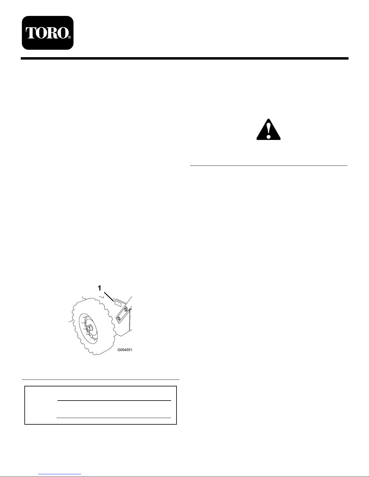
Figure1
identiesthelocationofthemodelandserialnumbers
onthemachine.Writethenumbersinthespace
provided.
Figure1
1.Modelandserialnumberlocation
ModelNo.
SerialNo.
Thismanualidentiespotentialhazardsandhas
safetymessagesidentiedbythesafetyalertsymbol
(Figure2),whichsignalsahazardthatmaycauseserious
injuryordeathifyoudonotfollowtherecommended
precautions.
Figure2
1.Safetyalertsymbol
Thismanualuses2wordstohighlightinformation.
Importantcallsattentiontospecialmechanical
informationandNoteemphasizesgeneralinformation
worthyofspecialattention.
ReplacementEngineOwner’sManualsmaybe
orderedthroughtheenginemanufacturer.
©2010—TheT oro®Company
8111LyndaleAvenueSouth
Bloomington,MN55420
Registeratwww.Toro.com.
OriginalInstructions(EN)
PrintedintheUSA
AllRightsReserved
Page 2
Safety
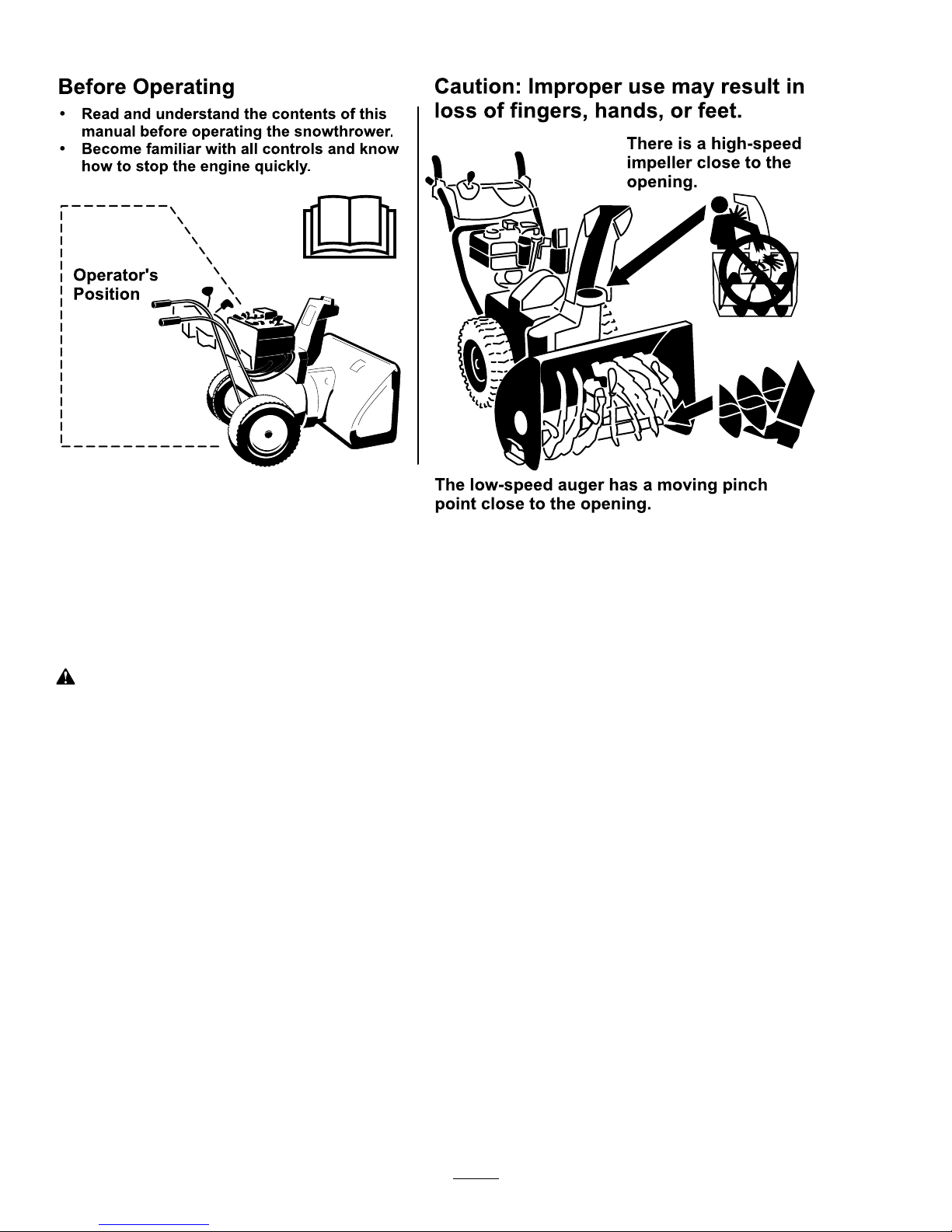
BeforeOperating
?
?
Readandunderstandthecontentsofthis
manualbeforeoperatingthesnowthrower .
Becomefamiliarwithallcontrolsandknow
howtostoptheenginequickly .
Operator 's
Position
Thelow-speedaugerhasamovingpinch
pointclosetotheopening.
Caution:Improperusemayresultin
lossoffingers,hands,orfeet.
Thereisahigh-speed
impellerclosetothe
opening.
ThismachinemeetsorexceedstheB71.3
specicationsoftheAmericanNationalStandards
Instituteineffectatthetimeofproduction.
Readandunderstandthecontentsofthismanual
beforeyoustarttheengine.
Thisisthesafetyalertsymbol.Itisusedtoalert
youtopotentialpersonalinjuryhazards.Obeyall
safetymessagesthatfollowthissymboltoavoid
possibleinjuryordeath.
Improperlyusingormaintainingthismachine
couldresultininjuryordeath.Toreducethis
potential,complywiththefollowingsafety
instructions.
Thismachineiscapableofamputatinghandsandfeet
andofthrowingobjects.Failuretoobservethefollowing
safetyinstructionscouldresultinseriousinjury.
Training
•Read,understandandfollowallinstructionsonthe
machineandinthemanual(s)beforeoperatingthis
machine.Bethoroughlyfamiliarwiththecontrols
andtheproperuseofthemachine.Knowhowto
stopthemachineanddisengagethecontrolsquickly.
•Neverallowchildrentooperatethemachine.Never
allowadultstooperatethemachinewithoutproper
instruction.
•Keeptheareaofoperationclearofallpersons,
particularlysmallchildren.
•Exercisecautiontoavoidslippingorfalling,
especiallywhenoperatingthemachineinreverse.
Preparation
•Thoroughlyinspecttheareawherethemachineis
tobeusedandremovealldoormats,sleds,boards,
wires,andotherforeignobjects.
•Disengageallclutchesandshiftintoneutralbefore
startingtheengine.
•Donotoperatethemachinewithoutwearing
adequatewintergarments.Avoidloosetting
clothingthatcangetcaughtinmovingparts.Wear
footwearthatwillimprovefootingonslippery
surfaces.
•Handlefuelwithcare;itishighlyammable.
–Useanapprovedfuelcontainer.
–Neveraddfueltoarunningengineorhotengine.
–Fillfueltankoutdoorswithextremecare.Never
llfueltankindoors.
–Neverllcontainersinsideavehicleorona
truckortrailerbedwithaplasticliner.Always
placecontainersontheground,awayfromyour
vehicle,beforelling.
2
Page 3

–Whenpractical,removegas-poweredmachine
fromthetruckortrailerandrefuelitonthe
ground.Ifthisisnotpossible,thenrefuelsuch
machineonatrailerwithaportablecontainer,
ratherthanfromagasolinedispensernozzle.
–Keepthenozzleincontactwiththerimof
thefueltankorcontaineropeningatalltimes,
untilrefuelingiscomplete.Donotuseanozzle
lock-opendevice.
–Replacegasolinecapsecurelyandwipeupspilled
fuel.
–Iffuelisspilledonclothing,changeclothing
immediately.
•Useextensioncordsandreceptaclesasspecied
bythemanufacturerforallmachineswithelectric
startingmotors.
•Adjustthecollectorhousingheighttocleargravel
orcrushedrocksurface.
•Neverattempttomakeanyadjustmentswhile
theengineisrunning(exceptwhenspecically
recommendedbymanufacturer).
•Alwayswearsafetyglassesoreyeshieldsduring
operationorwhileperforminganadjustmentor
repairtoprotecteyesfromforeignobjectsthatmay
bethrownfromthemachine.
Operation
•Donotputhandsorfeetnearorunderrotatingparts.
Keepclearofthedischargeopeningatalltimes.
•Exerciseextremecautionwhenoperatingonor
crossinggraveldrives,walks,orroads.Stayalertfor
hiddenhazardsortrafc.
•Afterstrikingaforeignobject,stoptheengine,
removethewirefromthesparkplug,thoroughly
inspectthemachineforanydamage,andrepairthe
damagebeforerestartingandoperatingthemachine.
•Ifthemachineshouldstarttovibrateabnormally,
stoptheengineandcheckimmediatelyforthecause.
Vibrationisgenerallyawarningoftrouble.
•Stoptheenginewheneveryouleavetheoperating
position,beforeuncloggingtheauger/impeller
housingordischargechute,andwhenmakingany
repairs,adjustmentsorinspections.
•Whencleaning,repairingorinspectingthemachine,
stoptheengineandmakecertaintheauger/impeller
andallmovingpartshavestopped.Disconnectthe
sparkplugwireandkeepthewireawayfromthe
plugtopreventsomeonefromaccidentallystarting
theengine.
•Donotruntheengineindoors,exceptwhenstarting
theengineandfortransportingthemachineinor
outofthebuilding.Opentheoutsidedoors;exhaust
fumesaredangerous.
•Exerciseextremecautionwhenoperatingonslopes.
•Neveroperatethemachinewithoutproperguards,
andothersafetyprotectivedevicesinplaceand
working.
•Neverdirectthedischargetowardpeopleorareas
wherepropertydamagecanoccur.Keepchildren
andothersaway.
•Donotoverloadthemachinecapacitybyattempting
toclearsnowattoofastarate.
•Neveroperatethemachineathightransportspeeds
onslipperysurfaces.Lookbehindandusecarewhen
operatinginreverse.
•Disengagepowertotheauger/impellerwhenthe
machineistransportedornotinuse.
•Useonlyattachmentsandaccessoriesapprovedby
themanufacturerofthemachine(suchaswheel
weights,counterweights,orcabs).
•Neveroperatethemachinewithoutgoodvisibility
orlight.Alwaysbesureofyourfooting,andkeepa
rmholdonthehandles.Walk;neverrun.
•Nevertouchahotengineormufer.
ClearingaCloggedDischarge
Chute
Handcontactwiththerotatingrotorbladesinsidethe
dischargechuteisthemostcommoncauseofinjury
associatedwithsnowthrowers.Neveruseyourhandto
cleanoutthedischargechute.
Toclearthechute:
•Shuttheengineoff!
•Wait10secondstobesuretheimpellerbladeshave
stoppedrotating.
•Alwaysuseaclean-outtool,notyourhands.
3
Page 4

MaintenanceandStorage
•Checkallfastenersatfrequentintervalsforproper
tightnesstobesurethemachineisinsafeworking
condition.
•Neverstorethemachinewithfuelinthefueltank
insideabuildingwhereignitionsourcesarepresent,
suchashotwaterheaters,spaceheaters,orclothes
dryers.Allowtheenginetocoolbeforestoringin
anyenclosure.
•AlwaysrefertotheOperator’sManualforimportant
detailsifthemachineistobestoredforanextended
period.
•Maintainorreplacesafetyandinstructionlabels,as
necessary.
•Runthemachineafewminutesafterthrowingsnow
topreventfreeze-upoftheauger/impellerblades.
ToroSnowthrowerSafety
Thefollowinglistcontainssafetyinformationspecic
toToroproductsorothersafetyinformationthatyou
mustknow.
•Rotatingauger/impellercancutofforinjure
ngersorhands.Staybehindthehandlesandaway
fromthedischargeopeningwhileoperatingthe
machine.Keepyourface,hands,feet,andany
otherpartofyourbodyorclothingawayfrom
movingorrotatingparts.
•Beforeadjusting,cleaning,inspecting,
troubleshooting,orrepairingthemachine,
stoptheengine,removetheignitionkey,and
waitforallmovingpartstostop.Disconnect
thewirefromthesparkplugandkeepitaway
fromthesparkplugtopreventsomeonefrom
accidentallystartingtheengine.
•Beforeleavingtheoperatingposition,stopthe
engine,removetheignitionkey,andwaitforall
movingpartstostop.
•Tounclogthedischargechute,stayintheoperating
positionandreleasethelefthand(traction)lever.
Whilerunningtheauger/impeller,pushdownon
thehandlestoraisethefrontofthemachineafew
inches(centimeters)offthepavement.Thenliftthe
handlesquicklytobumpthefrontofthemachineon
thepavement.Repeatifnecessaryuntilastreamof
snowcomesoutthedischargechute.
•Ifyoucannotunclogthedischargechutebybumping
thefrontofthemachine,stoptheengine,waitfor
allmovingpartstostop,andusetheclean-out
tool;neveruseyourhand.
•Ifashield,safetydevice,ordecalisdamaged,
illegible,orlost,repairorreplaceitbeforebeginning
operation.
•Donotsmokewhilehandlinggasoline.
•Donotusethemachineonaroof.
•Donottouchtheenginewhileitisrunningorsoon
afterithasstoppedbecausetheenginemaybehot
enoughtocauseaburn.
•Performonlythosemaintenanceinstructions
describedinthismanual.Beforeperformingany
maintenance,service,oradjustment,stoptheengine,
removetheignitionkey ,anddisconnectthewire
fromthesparkplug.Ifmajorrepairsareeverneeded,
contactanAuthorizedServiceDealer.
•Donotchangethegovernorsettingsontheengine.
•Whenstoringthemachineformorethan30days,
drainthefuelfromthefueltanktopreventa
potentialhazard.Storefuelinanapprovedfuel
container.Removethekeyfromtheignitionswitch
beforestoringthemachine.
•PurchaseonlygenuineTororeplacementpartsand
accessories.
4
Page 5
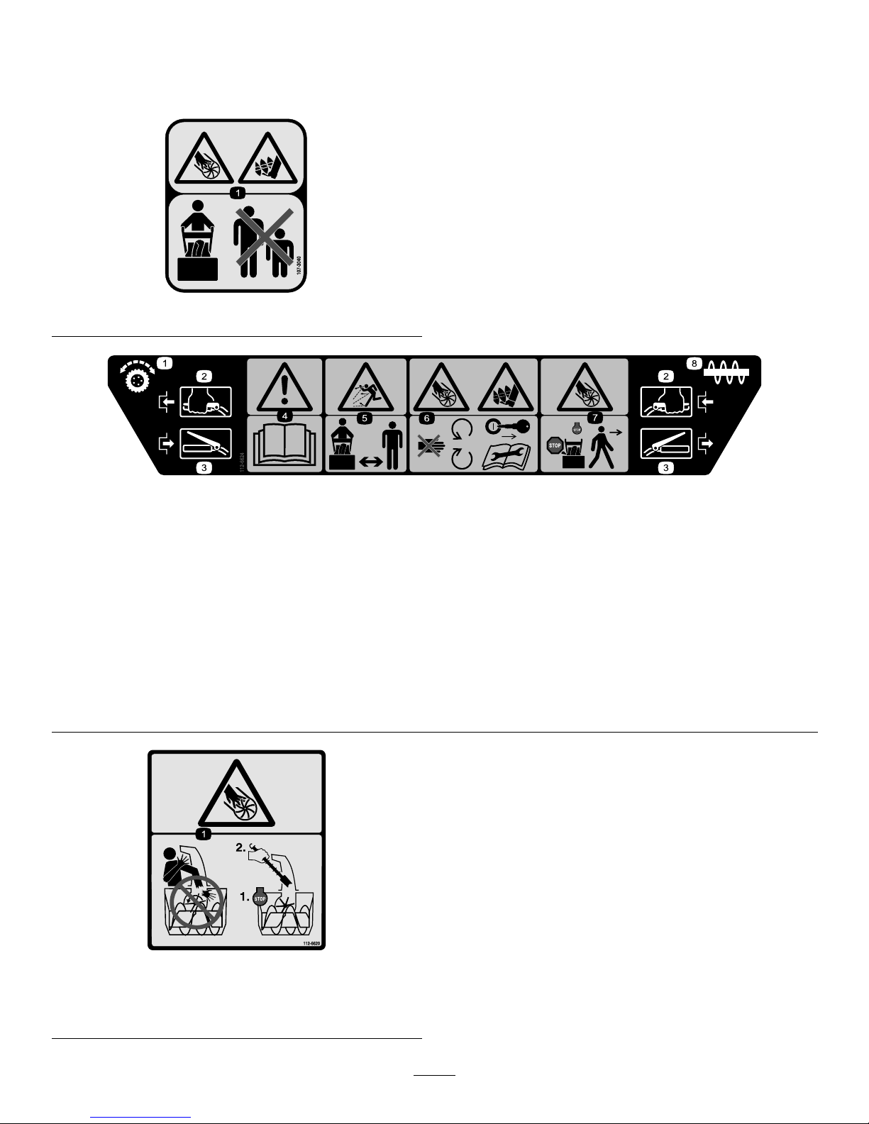
SafetyandInstructionalDecals
Important:Safetyandinstructiondecalsarelocatednearareasofpotentialdanger.Replacedamaged
decals.
107-3040
112-6624
1.Wheeldrive3.Disengage5.Thrownobject
hazard—keepbystanders
asafedistancefromthe
snowthrower.
7.Cutting/dismemberment
hazard,impeller—stop
theengineandwaitforall
movingpartstostopbefore
leavingtheoperator’s
position.
2.Engage4.Warning—readthe
Operator’sManual.
6.Cutting/dismemberment
hazard,impellerand
auger—stayawayfrom
movingparts,keepall
guardsandshieldsinplace;
removetheignitionkeyand
readtheinstructionsbefore
servicingorperforming
maintenance.
8.Auger
112-6620
1.Cutting/dismembermenthazard,impeller—donotplace
yourhandinthechute;stoptheenginebeforeleavingthe
operator’sposition,usethetoolclearthechute.
5
Page 6
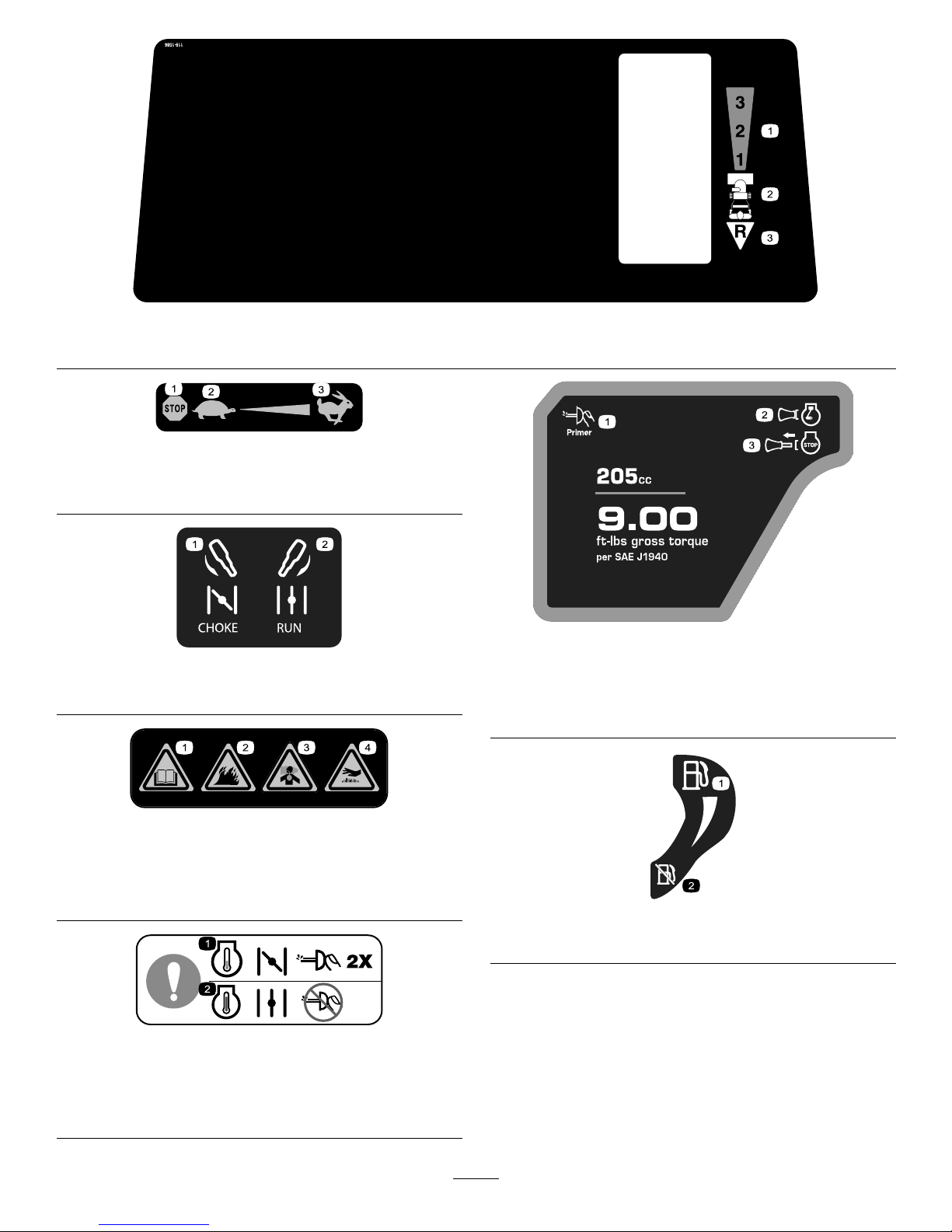
119-1586
1.Forwarddrivespeedsettings
2.Speedselector
3.Reversedrivespeedsetting
BriggsPartNo.273676
1.Stop
3.Fast
2.Slow
Briggs&StrattonPartNo.275949
1.Chokeon(Choke)2.Chokeoff(Run)
BriggsPartNo.276925
1.Warning—readthe
Operator’sManual.
3.Warning—toxicgas
inhalationhazard.
2.Warning—rehazard.
4.Warning—hot
surface/burnhazard.
BriggsPartNo.277566
1.Whenstartingacold
engine,closethechoke
andpresstheprimertwo
times.
2.Whenstartingawarm
engine,openthechoke
anddonotpressthe
primer.
Briggs&StrattonPartNo.277588
1.Primer3.Ignitionkeyout
(Engine—Stop)
2.Ignitionkeyin
(Engine—Run)
Briggs&StrattonPartNo.278866
1.Fuel—On2.Fuel—Off
6
Page 7

Setup
LooseParts
Usethechartbelowtoverifythatallpartshavebeenshipped.
ProcedureDescription
Qty.
Use
Handleassembly1
Bolts4
Bellevillewashers4
1
Flangenut1
Installthehandle.
Speedselectorrod
1
Cotterpin
1
2
Flatwasher1
Installthespeedselectorrod.
3
Flangelocknut1Installthetractionrod.
Clevispin
1
4
Cotterpin
1
Installtheauger/impellerdrivecontrol
linkage.
Chutecontrolrodassembly(rodand
bracket,wormgear,andbracket)
1
Bellevillewasher1
Bolt2
Carriagebolt
1
Locknut3
5
Curvedwasher
1
Installthechutecontrolrod.
6
Nopartsrequired
–
Filltheenginewithoil.
7
Nopartsrequired
–
Checkthetirepressure.
8
Nopartsrequired
–
Checktheskidsandscraper.
1
InstallingtheHandle
Partsneededforthisprocedure:
1Handleassembly
4Bolts
4Bellevillewashers
1Flangenut
Procedure
1.Removethetiestrapsthatsecurethecontrolrods
tothehandle.
2.Removetheaxlepinsfrombothwheelsandslidethe
wheelsoutwardontheaxleapproximately1inch(3
cm)(
Figure3).
Note:Savetheaxlepinssothatyoucaninstall
theminstep8.
7
Page 8
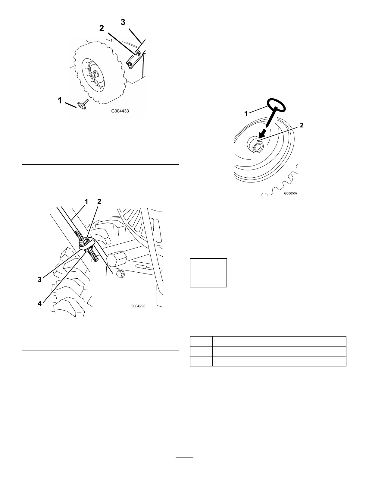
Figure3
1.Axlepin(2)
3.Handle
2.Capscrewandcurved
washer(4)
3.Threadaangenut(nottheangelocknut)withthe
angedownontothetractionrodattachedtothe
leftsideofthehandle(Figure4).
Figure4
1.Tractionrod3.Lowertractionrodloop
2.Flangenut4.Flangelocknut
4.Positiontheleftsideofthehandleagainsttheside
ofthemachineandinserttheendofthetractionrod
throughthelowertractionrodloopFigure4).
5.Aligntheholesintheleftsideofthehandlewith
theholesintheleftsideplate,andsecurethehandle
with2capscrewsandBellevillewashersuntilthey
arengertight(Figure3).
Note:TheconcavesideoftheBellevillewasher
goesagainsttheoutsideofthehandle.
6.Aligntheholesintherightsideofthehandlewith
theholesintherightsideplate,andsecurethe
handlewith2capscrewsandBellevillewashersuntil
theyarengertight.
7.Ensurethatthehandlesareatthesameheight,then
tightenthehandlefastenerssecurely .
8.Slidethewheelsoutwardandinserteachaxlepin
throughtheholeineachwheelhubandthroughthe
outerholeoftheaxle(
Figure5).
Figure5
1.Axlepin2.Holeinwheelhuband
outeraxleholealigned
Note:Ifyouinstalltirechains(optional),youmust
installtheaxlepinsthroughtheouteraxleholes.
2
InstallingtheSpeedSelector
Rod
Partsneededforthisprocedure:
1
Speedselectorrod
1
Cotterpin
1Flatwasher
Procedure
1.Pullthespeedselectorarm(Figure6)tothemost
outwardposition.
8
Page 9
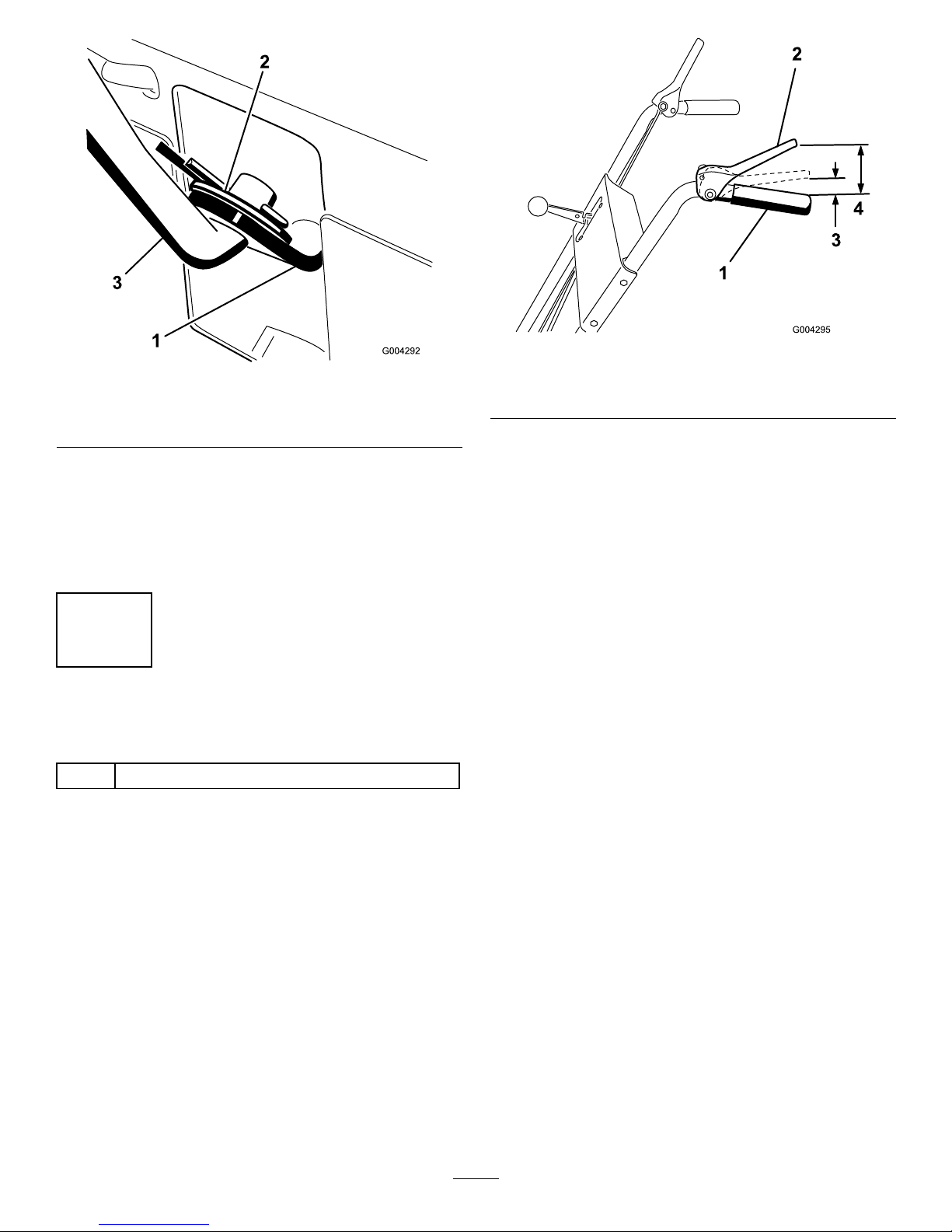
Figure6
1.Speedselectorarm3.Speedselectorrod
2.Flatwasherandcotterpin
2.Movethespeedselectorlever(Figure14)onthe
controlpaneltotheR(Reverse)position.
3.Installthespeedselectorrodintothespeedselector
arm,addaatwasherontheselectorrod,andsecure
itwithacotterpin(
Figure6).
3
InstallingtheTractionRod
Partsneededforthisprocedure:
1Flangelocknut
Procedure
1.Threadtheangelocknut(angesideup)ontothe
bottomofthetractioncontrolrod,belowtheloop
inthelowertractionrod(
Figure4).
2.Adjustthe2angenutsupordownonthetraction
roduntilthedistancebetweenthetopofthe
handgripandthebottomofthetractioncontrol
leverisapproximately4-1/2inches(11.4cm)as
showninFigure7.
Figure7
1.Handgrip
3.1to2inches(3to5cm)
2.Tractioncontrollever
4.4-1/2inches(11.4cm)
3.Tightenthe2angenutsuntiltheyarengertight.
4.Movethespeedselectorlever(Figure14)intothird
gear.
Note:Ifthespeedselectorleverdoesnotmove
intothirdgear,adjustthespeedselectorbefore
continuing.RefertoAdjustingtheSpeedSelector
inMaintenance.
5.Slowlypullthemachinebackwardwhileslowly
pressingthetractioncontrollevertowardthe
handgrip.
Note:Theadjustmentiscorrectwhenthewheels
stoprollingbackwardandthedistancebetweenthe
topofthehandgripandthebottomofthetraction
controlleveris1to2inches(3to5cm)asshown
in
Figure7.
6.Adjustthe2angenuts,ifnecessary,toobtainthe
properdistancebetweenthetopofthehandgripand
thebottomofthetractioncontrollever.
7.Tightentheangenutssecurely .
9
Page 10
4
InstallingtheAuger/Impeller
DriveControlLinkage
Partsneededforthisprocedure:
1
Clevispin
1
Cotterpin
Procedure
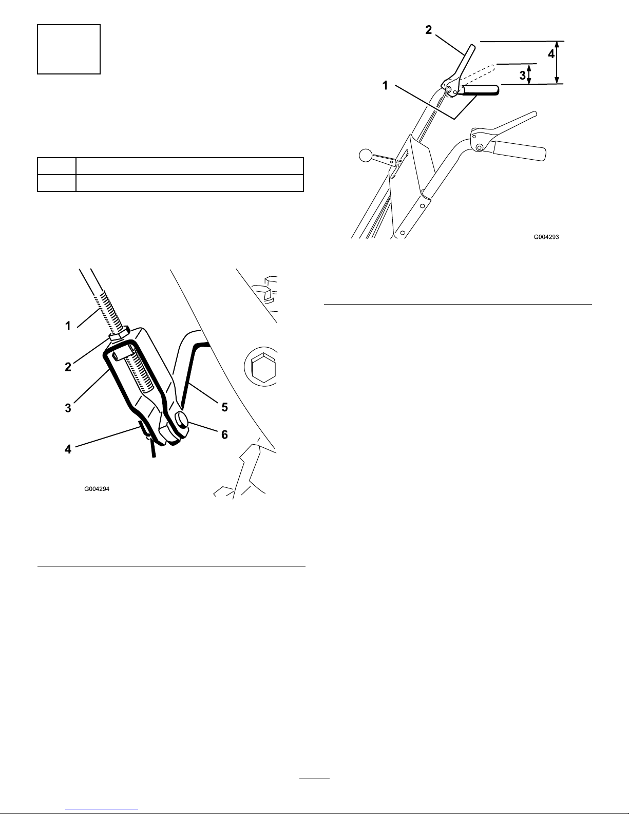
1.Loosenthejamnutabovetheclevisontheupper
controlrod(
Figure8).
Figure8
1.Uppercontrolrod
4.Cotterpin
2.Jamnut5.Lowercontrolrod
3.Clevis6.Clevispin
2.Aligntheholesintheclevisandthelowercontrol
rodandinserttheclevispin(
Figure8).
3.Checkthedistancebetweenthetopofthehandgrip
andthebottomoftheauger/impellerdrivecontrol
lever(Figure9).
Figure9
1.Handgrip
3.1to2inches(3to5cm)
2.Auger/impellercontrol
lever
4.5inches(12.7cm)
Note:Thedistanceshouldbeapproximately5
inches(12.7cm).
4.Presstheauger/impellerdrivecontrolleverslowly
towardthehandgrip.
Note:Theamountofforceneededtocompressthe
leverincreasesnoticeablywhenyouremovetheslack
fromtheauger/impellerdrivebelt(approximately
1/2ofthelevermovement).Theadjustmentis
correctwhentheforcebeginstoincreaseandthe
distancebetweenthetopofthehandgripandthe
bottomoftheauger/impellerdrivecontrolleveris1
to2inches(3to5cm)asshownin
Figure9.
Note:Iftheforcedoesnotnoticeablyincrease,
removethebeltcover(refertostep2ofReplacing
theTractionDriveBeltinMaintenance)andmeasure
2inches(5cm)abovethehandgripatthepoint
whereyouremovetheslackfromtheauger/impeller
drivebelt.
5.Toadjustthedistance:
A.Removetheclevispin.
B.Loosenthejamnut.
C.Threadtheclevisupordowntoincreaseor
decreasethedistancebetweenthetopofthe
handgripandthebottomoftheauger/impeller
drivecontrollever(
Figure8).
6.Whentheadjustmentiscorrect,installtheclevispin
andsecureitinplacewiththecotterpin(
Figure8).
7.Tightenthejamnuttosecuretheclevis(Figure8).
10
Page 11
5
InstallingtheChuteControl
Rod
Partsneededforthisprocedure:
1
Chutecontrolrodassembly(rodandbracket,worm
gear,andbracket)
1Bellevillewasher
2Bolt
1
Carriagebolt
3Locknut
1
Curvedwasher
Procedure
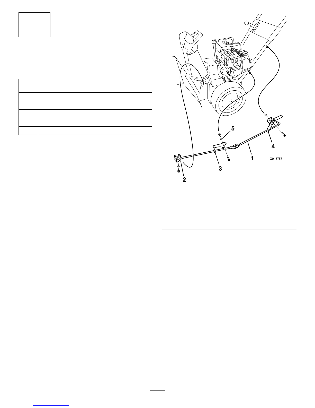
1.Securetheupperchutecontrolbracket(attachedto
thechutecontrolrod)totheupperleftsideofthe
handlewithaboltandalocknutFigure10.
Figure10
1.Chutecontrolrod
4.Upperchutecontrol
bracket
2.Wormgear,bracket,and
mountingange
5.Curvedwasher
3.Lowerchutecontrol
bracket
Note:Leavethelocknutloose.
2.Securethelowerchutecontrolbracket(attachedto
thechutecontrolrod)tothelowerleftsideofthe
handlewithabolt,acurvedwasher,aatwasher,
andalocknut(
Figure10).
Note:Thebracketshouldbefastenedonthe
outsideofthehandle,andtherodshouldbe
approximatelyparalleltothegroundandnottouch
thehandle.
Note:Leavethelocknutloose.
3.ApplyNo.2generalpurposegreasetotheworm
gear(Figure11).
11
Page 12
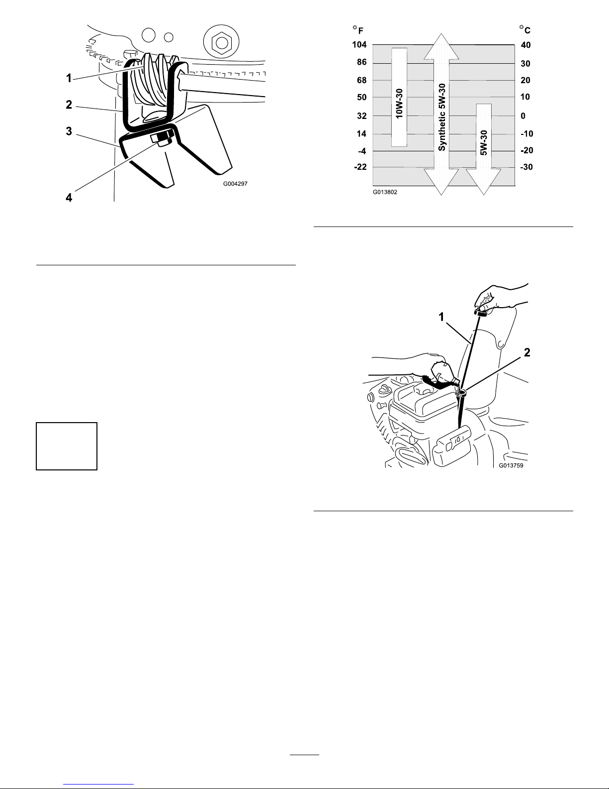
Figure11
1.Wormgear
3.Mountingange
2.Bracket4.Bolt,Bellevillewasher,
andlocknut
4.Looselymountthewormgearandthebrackettothe
mountingangewithabolt,aBellevillewasher,and
alocknutasshowninFigure11.
5.Slidethewormgearintotheteethofthechute
retainingringandtightenthelocknut(
Figure11).
6.Tightenthelocknutsthatsecurethe2chutecontrol
brackets(Figure10).
7.Checktheoperationofthechutecontrolrod,and
movethewormgearslightlyoutwardifitbinds.
6
FillingtheEnginewithOil
NoPartsRequired
Procedure
Yourmachinecomeswith20oz.(0.6l)ofoilinthe
engine.
Note:Beforestartingtheengine,checktheoillevel
andaddoilifnecessary.
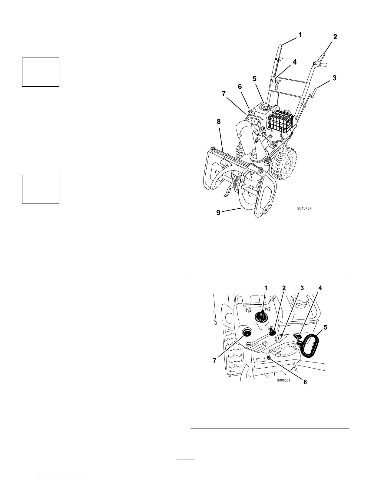
Max.ll:20oz.(0.6l),type:automotivedetergentoil
withanAPIserviceclassicationofSF ,SG,SH,SJ,SL,
orhigher.
Referto
Figure12toselectthebestoilviscosityforthe
outdoortemperaturerangeexpected.
Figure12
1.Movethemachinetoalevelsurfacetoensurean
accurateoillevelreading.
2.Cleanaroundthedipstick(Figure13).
Figure13
1.Dipstick2.Fillerhole
3.Removethedipstickbyrotatingthecap
counterclockwiseandpullingitout.
4.Slowlypourabout3/4ofthecrankcasecapacityof
oilintothecrankcase.
5.Wipethedipstickcleanwithacleancloth.
6.Installthedipstickintothellerneck,thenremoveit.
Note:Toensureanaccurateoillevelreading,you
mustfullyinstallthedipstick.
7.Readtheoillevelonthedipstick.
8.IftheoillevelisbelowtheAddmarkonthedipstick,
slowlypouronlyenoughoilintothellerholeto
raisetheoilleveltotheFullmarkonthedipstick.
Important:Donotoverllthecrankcasewith
oilandruntheengine;enginedamagewill
12
Page 13
result.Draintheexcessoiluntiltheoillevelon
thedipstickreadsFull.
9.Insertthedipstickintothellerneckandrotatethe
capclockwiseuntilitistight.
7
CheckingtheTirePressure
NoPartsRequired
Procedure
Thetiresareoverinatedatthefactoryforshipping.
Reducethepressureequallyinbothtirestobetween12
and15psi(82and103kPa).
8
CheckingtheSkidsand
Scraper
NoPartsRequired
Procedure
RefertoCheckingandAdjustingtheSkidsandScraper
inMaintenance.
ProductOverview
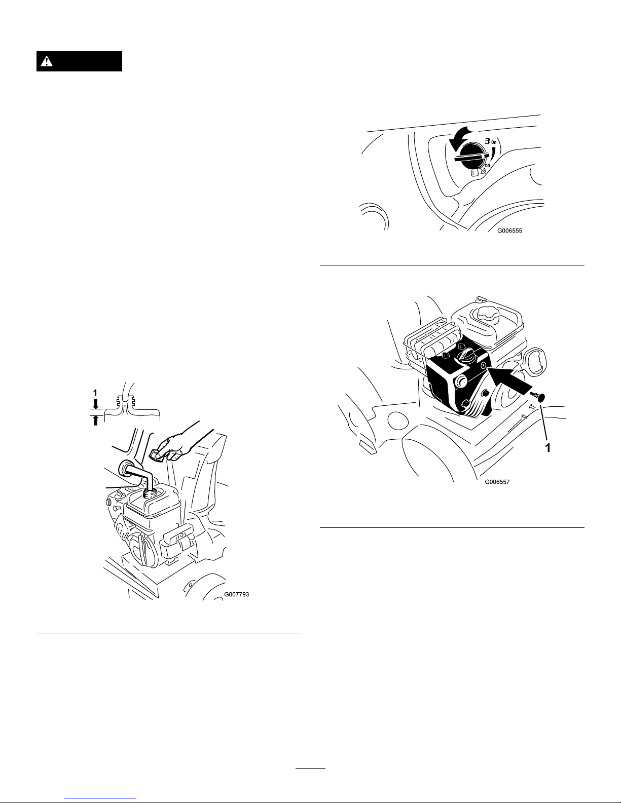
Figure14
1.Auger/impellerdrive
controllever
6.Oilll/dipstick
2.Tractioncontrollever
7.Chutedeectorhandle
3.Dischargechutecontrol
8.Snowclean-outtool
4.Speedselectorlever
9.Auger
5.Fueltankcap
Figure15
1.Choke
5.Recoilstarter
2.Ignitionswitch
6.Oildrainplug
3.Fuelshutoffvalve
7.Primer
4.Throttle
13
Page 14

Controls
•Auger/ImpellerDriveControlLever—T oengage
boththeaugerandimpeller,presstheleveragainst
therighthandgrip.Todisengage,releasethelever.
•TractionControlLever—Toengagethetraction
(wheeldrive),presstheleveragainsttheleft
handgrip.Tostopthetraction,releasethelever.
•SpeedSelectorLever—Thiscontrolhas4
positions:3forwardspeedsand1reverse.Tochange
speeds,movethespeedselectorlevertothedesired
position.Theleverlocksinanotchateachspeed
selection.
Note:Beforeshiftinggearsintooroutofreverse,
youmustreleasethetractioncontrollever.Youmay
shiftbetweenanyoftheforwardspeedswithout
releasingthetractioncontrollever.
•DischargeChuteControl—Rotatethedischarge
chutecontrolclockwisetomovethedischargechute
totheleft;counterclockwisetomovethechuteto
theright.
•ChuteDeectorHandle—Movethedeector
handleforwardtomovethesnowstreamdown;
moveitrearwardtomovethesnowstreamup.
•FuelshutoffValve—Closethevalvebyrotating
clockwise.Openthevalvebyrotatingit
counterclockwise.Closethevalvewhenyoudonot
usethemachine.
•IgnitionSwitch—Inserttheignitionkeybefore
startingtheengine.Tostoptheengine,removethe
key.
•Choke—RotatethechoketotheFullpositionto
startacoldengine.Asenginewarmsup,gradually
rotatethechoketotheOffposition.
•ThrottleLever—Movethethrottlelevertotheright
toincreasetheenginespeed;moveittotheleftto
decreasetheenginespeed.Movethethrottleleverto
theStoppositiontostoptheengine.
•Primer—Presstheprimertopumpasmall
amountofgasolineintotheengineforimproved
cold-weatherstarting.
•ElectricStarter—Theelectricstarterisontheright
sideoftheengine.Tostartthemachine,connect
theelectricstartertoanelectricpowersourcewith
anapprovedextensioncordandpressthestarter
button.
•RecoilStarter—Therecoilstarterisontheback
sideoftheengine.Pulltherecoilstartertostartthe
engine.
•SnowClean-outTool—Thesnowclean-outtool
isonthetopoftheaugerhousing.Usethistoolto
unclogthedischargechutewhenitbecomesclogged
withsnow.
Operation
Note:Determinetheleftandrightsidesofthemachine
fromthenormaloperatingposition.
FreewheelingorUsingthe
Self-propelDrive
Youcanoperatethemachinewiththeself-propelfeature
engagedordisengaged(freewheeling).
Tofreewheel,slidethewheelsinwardandinserttheaxle
pinsthroughtheouteraxleholes,butnotthroughthe
wheelhubs(
Figure16).
Figure16
Toself-propel,slidethewheelsoutwardandinsertthe
axlepinsthroughtheholesinthewheelhubsandthe
outeraxleholes(
Figure17).
Figure17
14
Page 15
FillingtheFuelTank
DANGER
Gasolineisextremelyammableandexplosive.A
reorexplosionfromgasolinecanburnyouand
others.
•Topreventastaticchargefromignitingthe
gasoline,placethecontainerand/ormachine
onthegroundbeforelling,notinavehicleor
onanobject.
•Fillthetankoutdoorswhentheengineiscold.
Wipeupspills.
•Donothandlegasolinewhensmokingoraround
anopenameorsparks.
•Storegasolineinanapprovedfuelcontainer,out
ofthereachofchildren.
Fillthefueltankwithfreshunleadedregulargasoline
fromamajorname-brandservicestation(Figure18).
Important:T oreducestartingproblems,add
fuelstabilizertothefuelallseason,mixingitwith
gasolinelessthan30daysold.
Do not add oil to
the gasoline.
Figure18
StartingtheEngine
1.Checktheengineoillevel.RefertoCheckingthe
EngineOilLevelinMaintenance.
2.Turnthefuelshutoffvalve1/4turncounterclockwise
toopenit(Figure19).
Figure19
3.Inserttheignitionkey(Figure20).
Figure20
1.Ignitionkey
4.Firmlypushintheprimerwithyourthumb2times
(15°For-9°Corabove)or4times(below15°For
-9°C),holdingtheprimerinforasecondbefore
releasingiteachtime(
Figure21).
15
Page 16
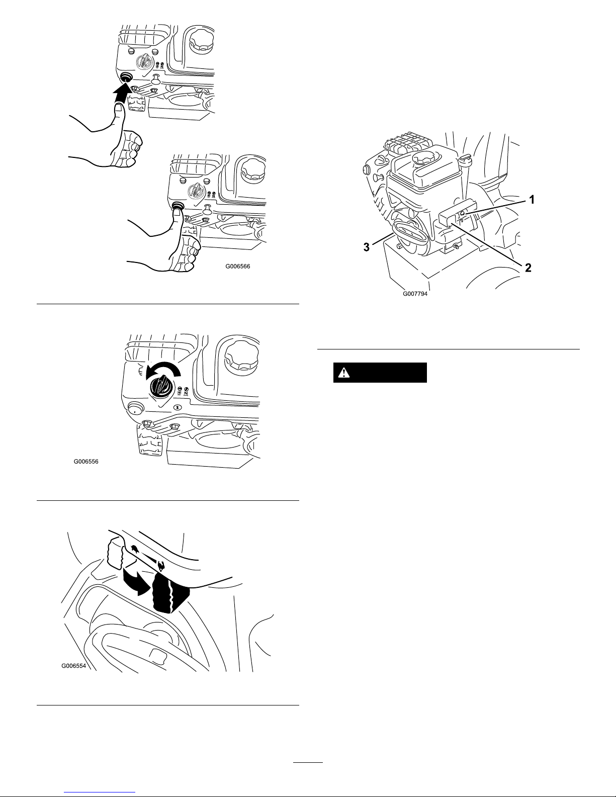
Figure21
5.RotatethechoketotheChokeposition(Figure22).
Figure22
6.MovethethrottletotheFastposition(Figure23).
Figure23
7.Connectanextensioncordtotheelectricstarterand
theoutlet.
Note:Tousetheelectricstarter,connectapower
cordtotheelectricstarterplug-inrstandthen
toapoweroutlet.UseonlyaUL-listed,16-gauge
extensioncordrecommendedforoutdoorusethat
isnotlongerthan50feet(15m).
8.Startthemachinebypullingtherecoilstarteror
pressingtheelectric-startbutton(Figure24).
Figure24
1.Electric-startbutton3.Recoilstarter
2.Electricstarterplug-in
WARNING
Theelectricalcordcanbecomedamaged,
causingashockorre.
Thoroughlyinspecttheelectricalcordbefore
usingthemachine.Ifthecordisdamaged,
donotoperatethemachine.Replaceorrepair
thedamagedcordimmediately.Contactan
AuthorizedServiceDealerforassistance.
Important:T opreventdamagingtheelectric
starter,runitinshortcycles(5seconds
maximum,thenwaitoneminutebeforetrying
tostartitagain).Iftheenginestilldoesnot
start,takethemachinetoanAuthorizedService
Dealerforservice.
9.Disconnecttheextensioncordfromthepoweroutlet
rstandthenfromthemachine(electricstartonly).
10.Allowtheenginetowarmupforseveralminutes,
thenmovethechoketowardtheRunposition.Wait
fortheenginetorunsmoothlybeforeeachchoke
adjustment.
16
Page 17
WARNING
Ifyouleavethemachinepluggedintoapower
outlet,someonecaninadvertentlystartthemachine
andinjurepeopleordamageproperty.
Unplugthepowercordwheneveryouarenot
startingthemachine.
StoppingtheEngine
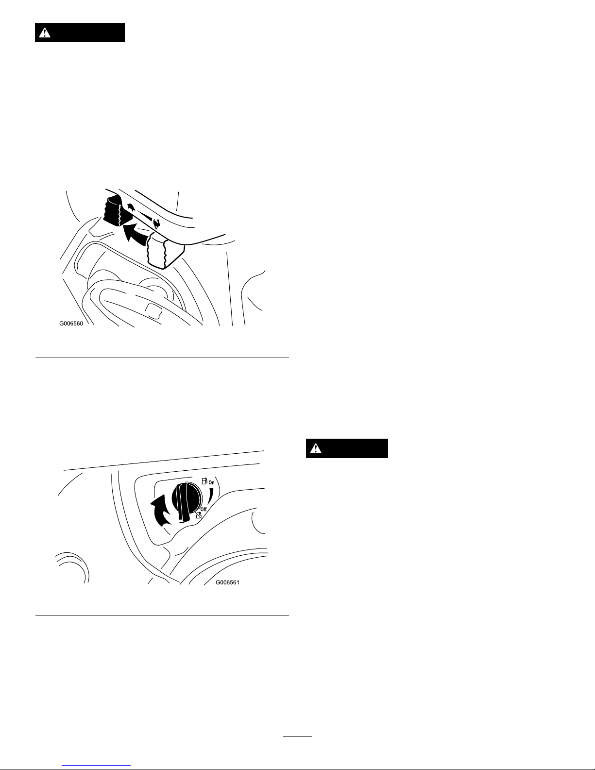
1.MovethethrottletotheSlowposition,andthento
theStopposition(
Figure25).
Figure25
2.Waitforallmovingpartstostopbeforeleavingthe
operatingposition.
3.Removetheignitionkey.
4.Closethefuelshutoffvalvebyrotatingitclockwise
(
Figure26).
Figure26
5.Pulltherecoilstarter3or4times.Thishelpsprevent
therecoilstarterfromfreezingup.
6.Waitforallmovingpartstostopbeforeleavingthe
operatingposition.
UncloggingtheDischarge
Chute
Iftheauger/impellerisrunningbutthereisnosnow
comingoutofthedischargechute,thedischargechute
maybeclogged.
Ifthedischargechutebecomesclogged,stopthe
engine,waitforallmovingpartstostop,anduse
theclean-outtool—neveruseyourhand.
PreventingFreeze-up
•Insnowyandcoldconditions,somecontrolsand
movingpartsmayfreeze.Donotuseexcessive
forcewhentryingtooperatefrozencontrols.If
youhavedifcultyoperatinganycontrolorpart,
starttheengineandletitrunforafewminutes.
•Afterusingthemachine,lettheenginerunfora
fewminutestopreventmovingpartsfromfreezing.
Engagetheauger/impellertoclearanyremaining
snowfrominsidethehousing.Rotatethedischarge
chutecontroltopreventitfromfreezing.Stopthe
engine,waitforallmovingpartstostop,andremove
alliceandsnowfromthemachine.
•Withtheengineoff,pulltherecoilstarterhandle
severaltimestopreventtherecoilstarterfrom
freezingup.
OperatingTips
DANGER
Whenthemachineisinoperation,theimpellerand
augercanrotateandcutofforinjurehandsandfeet.
•Beforeadjusting,cleaning,inspecting,
troubleshooting,orrepairingthemachine,stop
theengineandwaitforallmovingpartstostop.
Disconnectthewirefromthesparkplugand
keepitawayfromtheplugtopreventsomeone
fromaccidentallystartingtheengine.
•Removeanobstructionfromthedischarge
chute;refertoUncloggingtheDischargeChute.
Ifnecessary,usetheclean-outtool,notyour
hands,toremoveanobstructionfromthe
dischargechute.
•Staybehindthehandlesandawayfromthe
dischargeopeningwhileoperatingthemachine.
•Keepface,hands,feet,andanyotherpartof
yourbodyorclothingawayfromconcealed,
moving,orrotatingparts.
17
Page 18

WARNING
Therotorbladescanthrowstones,toys,andother
foreignobjectsandcauseseriouspersonalinjuryto
theoperatorortobystanders.
•Keeptheareatobeclearedfreeofallobjects
thattherotorbladescouldpickupandthrow.
•Keepallchildrenandpetsawayfromthearea
ofoperation.
•AlwayssetthethrottlelevertotheFastposition
whenthrowingsnow.
•Iftheengineslowsdownunderaloadorthewheels
slip,shiftthemachineintoalowergear.
•Ifthefrontofthemachineridesup,shiftthe
machineintoalowergear.Ifthefrontcontinuesto
rideup,liftuponthehandles.
Maintenance
Note:Determinetheleftandrightsidesofthemachinefromthenormaloperatingposition.
RecommendedMaintenanceSchedule(s)
MaintenanceService
Interval
MaintenanceProcedure
Afterthersthour
•Inspectandadjustthetractiondrivebelt.
•Inspectandadjusttheauger/impellerdrivebelt.
Aftertherst5hours
•Changetheengineoil.
Beforeeachuseordaily
•Checktheengineoillevelandaddoilifnecessary.
•Inspectandadjustorreplacethetractiondrivebeltwhennecessary.
•Inspectandadjustorreplacetheauger/impellerdrivebeltwhennecessary.
Every20hours
•Lubricatethemachine.
Every50hours
•Changetheengineoil.
Every100hours
•Inspectthesparkplug.Replaceand/orgapitifnecessary.
Yearly
•Checktheskidsandthescraperandadjustthemifnecessary.
•Checktheaugergearboxoilandaddoilifnecessary.
•Changetheengineoil.
Yearlyorbeforestorage
•Lubricatethemachine.
•Drainthegasolineandruntheenginetodryoutthefueltankandthecarburetorat
theendoftheseason.
Important:Refertoyourengineoperator’smanualforadditionalmaintenanceprocedures.Forengine
adjustments,repairs,orwarrantyservicenotcoveredinthismanual,contactanAuthorizedBriggs
&StrattonServicingDealer.
CAUTION
Ifyouleavethewireonthesparkplug,someonecouldaccidentlystarttheengineandseriouslyinjure
youorbystanders.
Disconnectthewirefromthesparkplugbeforeyoudoanymaintenance.Setthewireasidesothatitdoes
notaccidentallycontactthesparkplug.
PreparingforMaintenance
1.Movethemachinetoalevelsurface.
2.Stoptheengineandwaitforallmovingpartstostop.
3.Disconnectthesparkplugwire.RefertoInspecting
andReplacingtheSparkPlug.
CheckingtheEngineOilLevel
ServiceInterval:Beforeeachuseordaily
Eachtimebeforeusingthemachine,rstensurethat
theoillevelisbetweentheAddandtheFullmarkson
thedipstick.
18
Page 19
1.Cleanaroundthedipstick(Figure13).
2.Removethedipstickbyrotatingthecap
counterclockwiseandpullingitout.
3.Wipethedipstickcleanwithacleancloth.
4.Installthedipstickintothellerneck,thenremoveit.
Note:Toensureanaccurateoillevelreading,you
mustfullyinstallthedipstick.
5.Readtheoillevelonthedipstick.
6.IftheoillevelisbelowtheAddmarkonthedipstick,
slowlypouronlyenoughoilintothellerholeto
raisetheoilleveltotheFullmarkonthedipstick.
Note:Useonlyahigh-quality,SAE5W-30or
SAE10detergentoilthathastheAmerican
PetroleumInstitute(API)serviceclassicationSF,
SG,SH,orSJ.Forextremelycoldconditions(below
0°For-18°C),use0W -30detergentoilthathas
theAmericanPetroleumInstitute(API)service
classicationSF,SG,SH,orSJ.
Important:Donotoverllthecrankcasewith
oilandruntheengine;enginedamagewill
result.Draintheexcessoiluntiltheoillevelon
thedipstickreadsFull.
7.Insertthedipstickintothellerneckandrotatethe
capclockwiseuntilitistight.
AdjustingtheSkidsand
Scraper
ServiceInterval:Yearly
Adjusttheskidsandthescraperinitiallyandthenas
neededtoensurethattheaugerdoesnotcontactthe
pavedorgravelsurface.Also,adjustthemasneededto
compensateforwear.
1.Movethemachinetoalevelsurface.
2.Checkthetirepressureinthetires.RefertoChecking
theTirePressureinSetup.
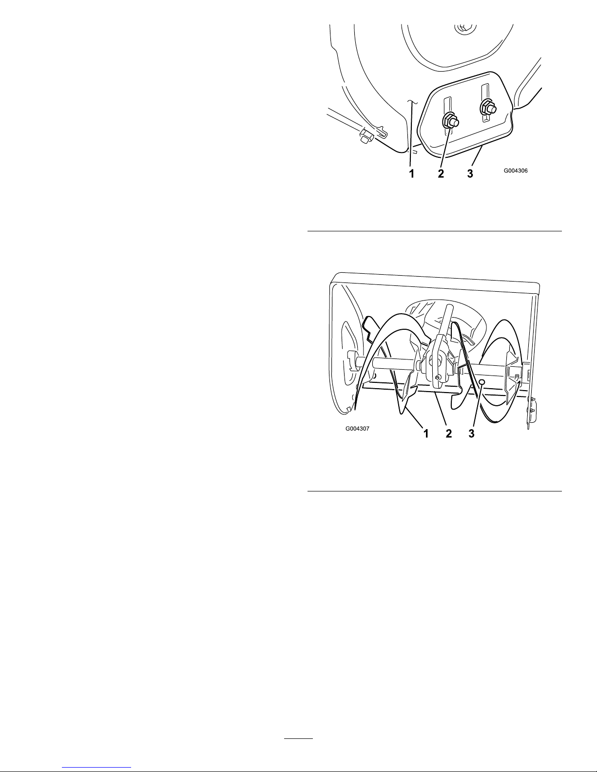
3.Loosenthe4angenutsthatsecurebothskidsto
theaugersideplates(
Figure27)untiltheskidsslide
upanddowneasily.
Figure27
1.Augersideplate(2)3.Skid(2)
2.Flangenuts(4)
4.Supporttheaugerbladessothattheyare1/8inch(3
mm)offtheground(
Figure28).
Figure28
1.Augerblade
3.Mountingscrew(5)
2.Scraper
5.Checkthescraperadjustment.Thescrapershouldbe
1/8inch(3mm)aboveandparalleltoalevelsurface.
A.ForConcreteandAsphaltSurfaces:
Ifthemachinedoesnotclearthesnowclose
enoughtothepavement,adjusttheskidsto
lowerthescraper;ifthepavementsurfacesare
cracked,rough,oruneven,adjusttheskidsto
raisethescraper.
B.ForGravelSurfaces:
Supporttheaugerbladesafewinches(cm)above
theground,andadjusttheskidstopreventthe
machinefrompickinguprocks.
6.Toadjustthescraper,loosenthe5mounting
screws(Figure28),levelthescraper,andtightenthe
mountingscrews.
19
Page 20
7.Movetheskidsdownasfaraspossible.
8.Tightenthe4angenutsthatsecurebothskidsto
theaugersideplates(Figure27).
AdjustingtheSpeedSelector
Adjustthespeedselectorlinkageinitiallyandwhenthe
machineisslow,rstgearhasnospeed,orthespeed
selectorleverdoesnotmoveintothirdgear.
1.Draingasolinefromthefueltankandtheengine
oilfromthecrankcase.RefertoEmptyingtheFuel
TankandtoChangingtheEngineOil.
2.Tipthemachineforwardandblockitsothatit
cannotfall.
3.Removethe4ange-headboltsthatsecurethe
bottomcovertotheframeandremovethecover
(
Figure34).
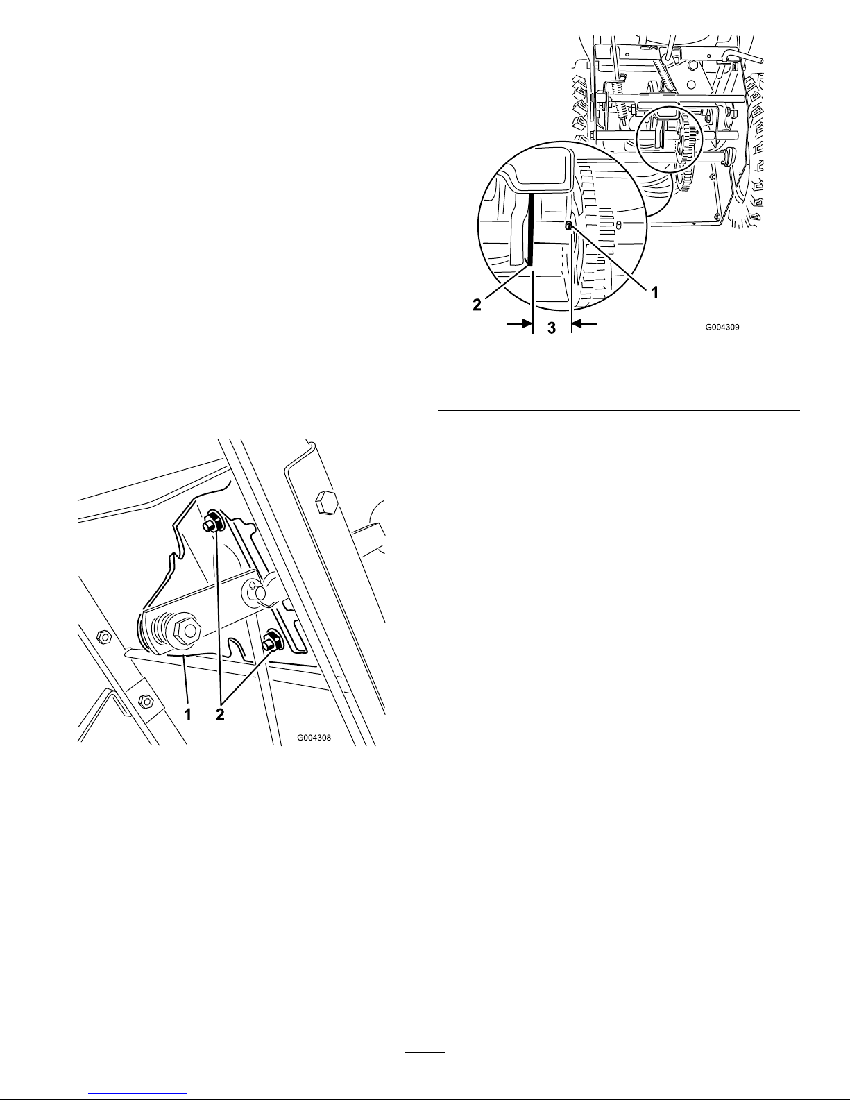
4.Loosentheangenutsthatsecuretheselectorplate
tothecontrolpanel(Figure29).
Figure29
1.Speedselectorplate
2.Flangenuts
5.Shiftthespeedselectorlevertothirdgearandpush
downonthespeedselectorplatetomovethedrive
assemblytotheright.
Note:Thedriveassemblyshouldbe1/8inch(3
mm)fromtherollpin;ifnot,slidetheselectorplate
(
Figure29)untilthegapis1/8inch(3mm);refer
toFigure30.
Figure30
1.Rollpin
3.1/8inch(3mm)
2.Driveassembly
6.Withthedriveassembly1/8inch(3mm)fromthe
rollpin,tightentheangenutsthatsecurethespeed
selectorplate.
7.ShiftthespeedselectorlevertotheR(Reverse)
positionandbacktothirdgeartocheckthe
adjustment.
8.Ifthespacebetweentherollpinandthedrive
assemblyismorethan3/16inch(5mm),repeat
steps
3through6.
9.Installthebottomcoverandreturnthemachineto
theuprightposition.
CheckingtheAugerGearbox
Grease
ServiceInterval:Yearly
Theaugergearboxispackedwith5oz.(140g)of
LubriplateMAG-1(alow-temperature,high-pressure
grease)andissealedatthefactory.Thepipeplug
(Figure31)isforfactoryuseonly;youdonotneedto
checkoraddgrease.Ifthegearboxisleakinggrease,
contactanAuthorizedServiceDealer.
20
Page 21
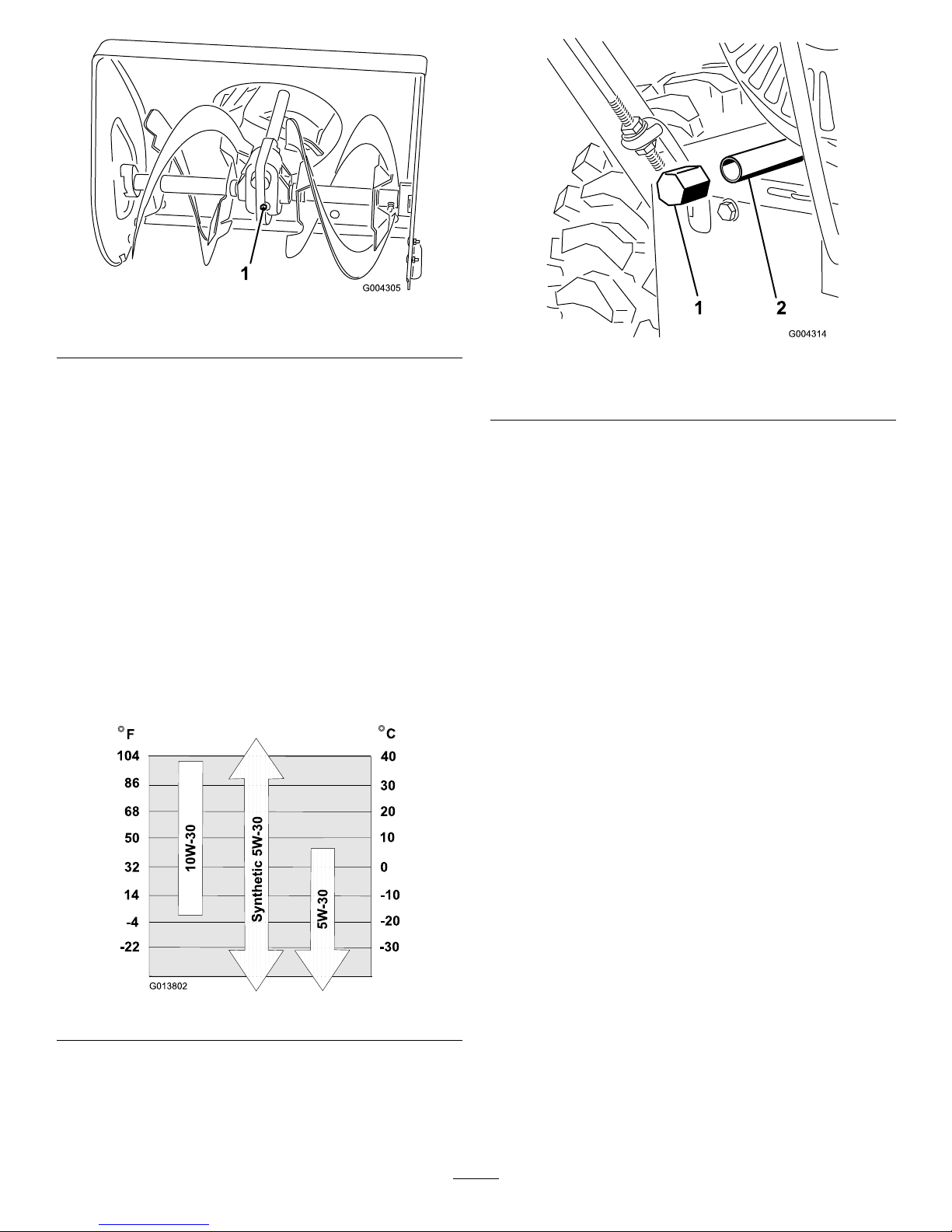
Figure31
1.Pipeplug
ChangingtheEngineOil
ServiceInterval:Aftertherst5hours
Yearly
Every50hours
Ifpossible,runtheenginejustbeforechangingthe
oilbecausewarmoilowsbetterandcarriesmore
contaminants.
Max.ll:20oz.(0.6l),type:automotivedetergentoil
withanAPIserviceclassicationofSF ,SG,SH,SJ,SL,
orhigher.
RefertoFigure32toselectthebestoilviscosityforthe
outdoortemperaturerangeexpected.
Figure32
1.Blockuptherearofthemachine.
2.Removetheleftwheel.
3.Cleantheareaaroundtheoildrainplug(Figure33).
Figure33
1.Oildrainplug
2.Drainextension
4.Slideanoildrainpanunderthedrainextensionand
removetheoildrainplug(Figure33).
Note:Placeafunnelunderthedrainextensionso
theoildrainsdirectlyintotheoildrainpanandaway
fromthemachine.
5.Draintheoil.
Note:Disposeoftheusedoilproperlyatalocal
recyclingcenter.
6.Installtheoildrainplug.
7.Installtheleftwheel.
8.Fillthecrankcasewithoil.RefertoFillingthe
EnginewithOilinSetup.
9.Wipeupanyspilledoil.
LubricatingtheMachine
ServiceInterval:Every20hours
Yearlyorbeforestorage
Lightlylubricateallmovingpartsofthemachine
afterevery20operatinghoursandattheendofthe
snowthrowingseason.
Important:Donotgetoilorgreaseontherubber
wheelorfrictiondriveplatebecausethewheelwill
slipandtherubbermaydeteriorate.
1.Draingasolinefromthefueltankandtheoilfrom
thecrankcase.RefertoEmptyingtheFuelTankand
toChangingtheEngineOil.
2.Tipthemachineforwardontotheauger/impeller
housingandblockitsothatitcannotfall.
3.Removethe4ange-headboltsthatsecurethe
bottomcoverandremovethecover(Figure34).
21
Page 22
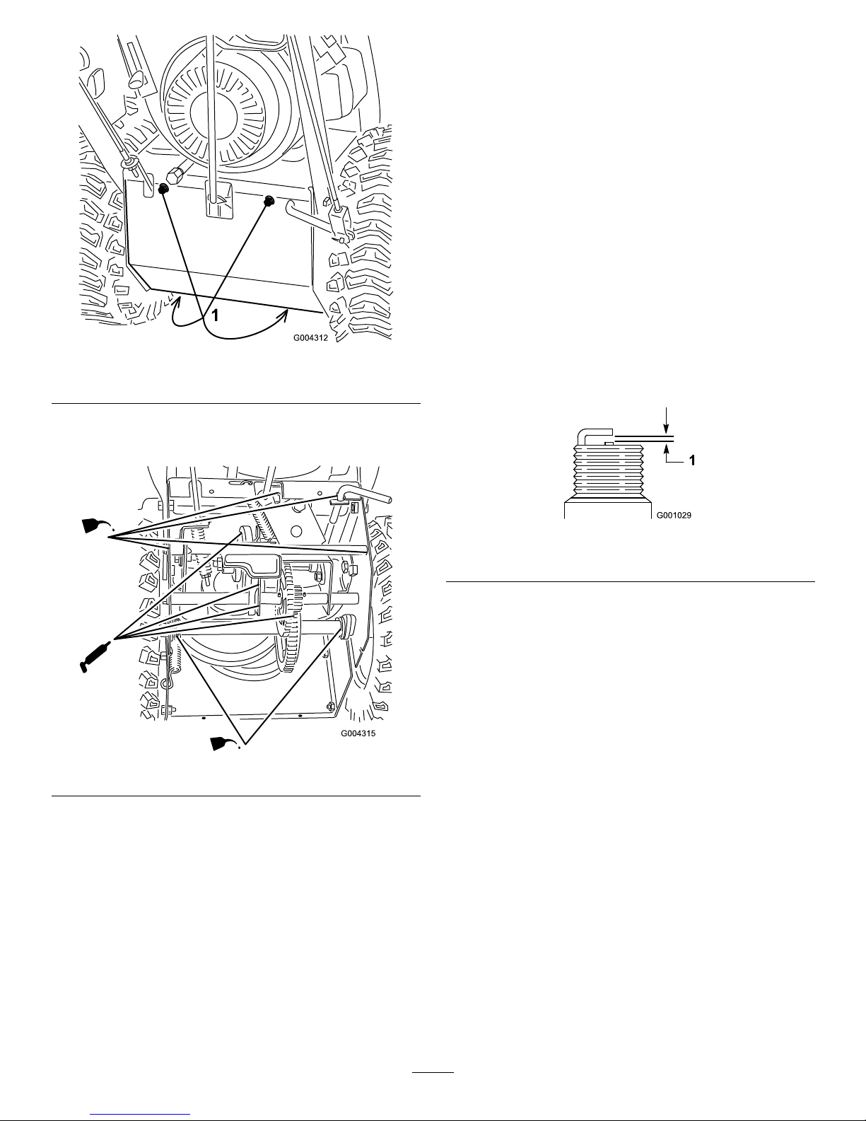
Figure34
1.Flange-headbolts
4.Lightlylubricatethemachinewithlightoilasshown
in
Figure35.
Figure35
Important:Donotexcessivelyoilthemachine;
extraoilmayenterthetractiondriveandcause
thetractiondrivebelttoslip.
5.Wipeupanyexcessoil.
6.Greasethemachineasshownin
Figure35.
7.Wipeupanyexcessgrease.
8.Installthebottomcover.
9.Returnthemachinetoitsuprightposition.
InspectingandReplacingthe
SparkPlug
ServiceInterval:Every100hours
UseaChampionQC12YCorequivalentsparkplug.
Checkandgapthesparkyearly,andreplacetheplug
ifnecessary.
1.Cleanaroundthebaseofthesparkplug.
2.Removethesparkplug.
3.Examinethesparkplugandreplaceitifitiscracked,
fouled,dirty,oriftheelectrodesareworn.
Important:Donotcleantheelectrodesbecause
gritcouldenterthecylinderanddamagethe
engine.
4.Setthegapbetweentheelectrodesonthesparkplug
at0.030inch(0.76mm)(
Figure36).
Figure36
1.0.030inch(0.76mm)
5.Installthesparkplugbyhandandthentorqueitto
15ft-lb(20.4N-m).
Note:Ifyoudonothaveatorquewrench,tighten
theplugrmly.
AdjustingtheTractionDrive
Belt
ServiceInterval:Afterthersthour
Beforeeachuseordaily
Adjustthetractiondrivebeltaftertherstoperating
hour,afterevery5operatinghoursthereafter,andwhen
thespeedselectorlevershiftsproperlybutthemachine
doesnotdriveintheforwardorreversespeeds.
1.Checkandadjustthetractiondriveasdescribedin
InstallingtheTractionRodinSetup.
2.Iftheproblempersistsafteradjustingthelinkage,
contactanAuthorizedServiceDealer.
22
Page 23
ReplacingtheTractionDrive
Belt
Ifthetractiondrivebeltbecomesworn,oil-soaked,or
otherwisedamaged,replacethebelt.
1.Draingasolinefromthefueltankandtheoilfrom
thecrankcase.RefertoEmptyingtheFuelTankand
toChangingtheEngineOil.
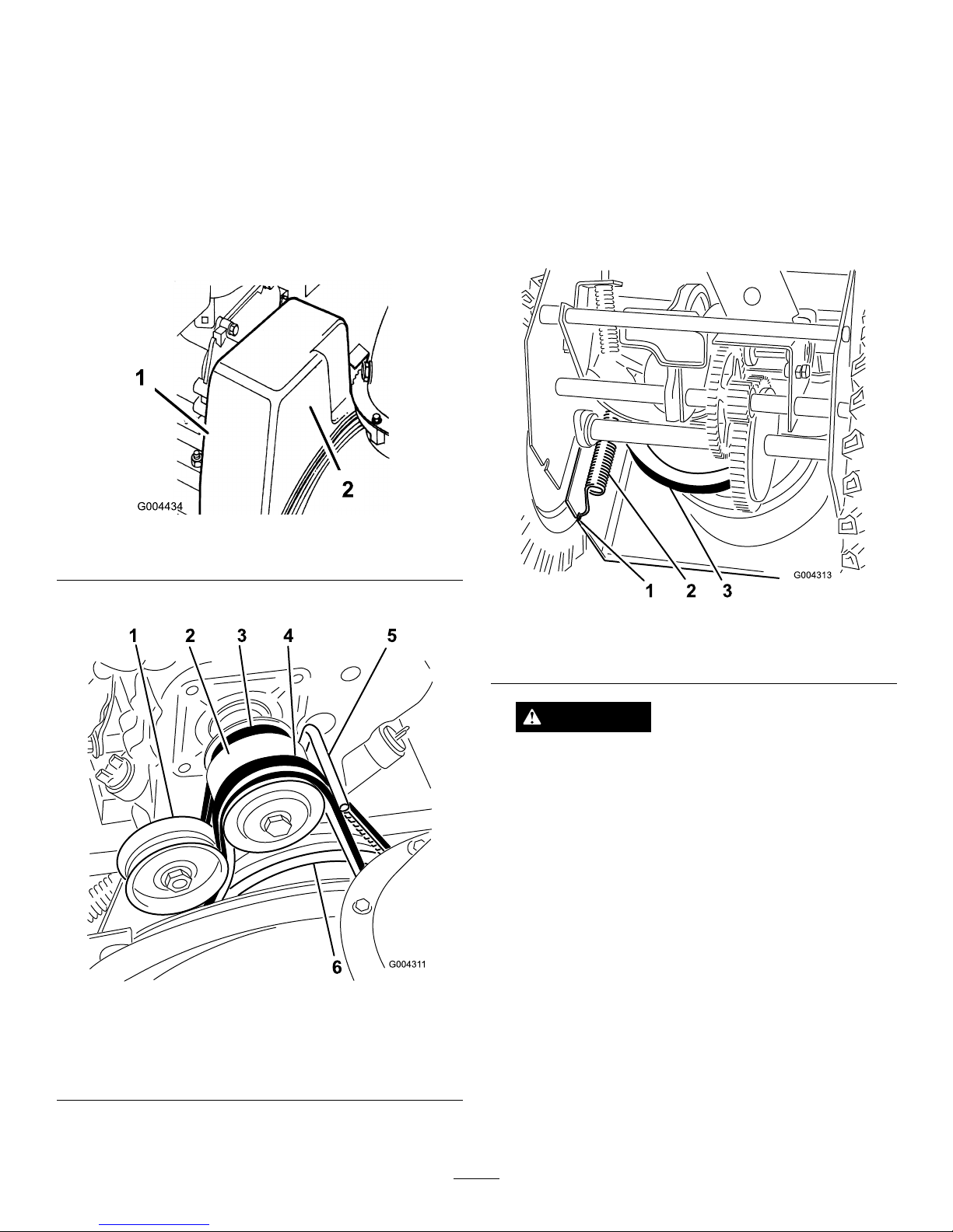
2.Removethe2ange-headboltsthatholdthebelt
coverinplaceandsetthecoveraside(Figure37).
Figure37
1.Flange-headbolt(2)
2.Beltcover
3.Loosenthebeltguide(Figure38).
Figure38
1.Idlerpulley
4.Auger/impellerdrivebelt
2.Enginepulley5.Beltguide
3.Tractiondrivebelt
6.Largeauger/impeller
pulley
4.Removetheauger/impellerdrivebeltfromthe
enginepulleyandthelargeauger/impellerpulley
(Figure38).
5.Tipthemachineforwardandblockitsothatit
cannotfall.
6.Removethe4ange-headboltsthatsecurethe
bottomcovertotheframeandremovethecover
(
Figure34).
7.Disconnectthespringfromthenotchinthebottom
edgeofthesideplate(Figure39).
Figure39
1.Notchinsideplate3.Largetractionpulley
2.Spring
CAUTION
Thespringisunderheavytensionandcould
injuretheyouorabystanderifyoudonot
carefullyremoveit.
Carefullyremovethespring.
8.Setthemachineupright.
9.Removethetractiondrivebeltfromtheengine
pulleyandthelargetractionpulley(Figure38).
10.Installanewbeltaroundthelargetractionpulley.
11.Loopthebeltovertheenginepulley,ensuringthat
thebeltisontheinsideofthebeltguide(Figure38).
12.Tipthemachineforwardandblockitsothatit
cannotfall.
13.Hookthespringintothenotchinthebottomedge
ofthesideplate(Figure39).
14.Replacethebottomcoverwiththe4ange-head
bolts.
15.Setthemachineupright.
23
Page 24

16.Installtheauger/impellerdrivebeltaroundthelarge
auger/impellerpulleyandenginepulley,ensuring
thatthebeltisontheinsideoftheidlerpulleyand
thebeltguide(
Figure38).
17.Adjustthebeltguidesothatthereis1/8inch(3mm)
ofclearancebetweentheauger/impellerdrivebelt
andtheguide,andsecurethebeltguidewhenthe
auger/impellerdrivebeltistight.
18.Checktheauger/impellerdrivelinkageandadjustit
ifnecessary.Refertosteps4through7ofInstalling
theAuger/ImpellerDriveControlLinkageinSetup.
19.Installthebeltcover.
AdjustingtheAuger/Impeller
DriveBelt
ServiceInterval:Afterthersthour
Beforeeachuseordaily
Operatingthemachinewithanauger/impellerdrivebelt
thatslipsdecreasesthesnowthrowingperformanceand
damagesthebelt.Checktheauger/impellerdrivebelt
forthepropertensionaftertherstoperatinghour,then
checkandadjustthebeltwhennecessary.
DANGER
Improperlyadjustingtheauger/impellermaycause
ittoturnwhendisengaged.Arotatingaugeror
impellercancutofforinjurengers,hands,orfeet.
•Keepyourface,hands,feet,andanyotherpart
ofyourbodyorclothingawayfromconcealed,
moving,orrotatingparts.
•Ensurethattheimpellerbrakearmclearance
ismaintained.
•Donotadjusttheauger/impellerdrivebelttoo
tightbecauseitmaycausetheauger/impellerto
turnwhenthecontrolleverisintheDisengaged
position.Ifthisoccurs,decreasethebelt
tension.
1.CheckandadjustthebeltasinstructedinInstalling
theAuger/ImpellerDriveControlLinkageinSetup.
2.Connectthewiretothesparkplug.
3.Checkthebelttensionbyoperatingtheauger.
4.Ifthebeltstillslips,replaceit.RefertoReplacingthe
Auger/ImpellerDriveBelt.
Important:Donotoperatethemachineif
theaugerandtheimpellerrotatewhenyou
disengagetheauger/impellerdrivecontrollever.
ReplacingtheAuger/Impeller
DriveBelt
Iftheauger/impellerdrivebeltbecomesworn,
oil-soaked,orotherwisedamaged,replacethebelt.
1.Removethe2ange-headboltsthatholdthebelt
coverinplaceandsetthecoveraside(
Figure37).
2.Loosenthebeltguide(Figure38).
3.Removetheauger/impellerdrivebeltfromthe
enginepulleyandthelargeauger/impellerpulley
(
Figure38).
4.Installanewbeltaroundthelargeauger/impeller
pulley(Figure38).
5.Loopthebeltovertheenginepulley,ensuringthat
thebeltisontheinsideoftheidlerpulleyandthe
beltguide(Figure38).
6.Adjustthebeltguidesothatthereis1/8inch(3mm)
ofclearancebetweentheauger/impellerdrivebelt
andtheguide,andsecurethebeltguide.
7.Checkandadjusttheauger/impellerdrivebeltas
instructedinInstallingtheAuger/ImpellerDrive
ControlLinkageinSetup.
8.Installthebeltcover.
Important:Donotoperatethemachineif
theaugerandtheimpellerrotatewhenyou
disengagetheauger/impellerdrivecontrollever.
Storage
WARNING
•Gasolinevaporscanexplode.
•Donotstoregasolinemorethan30days.
•Donotstorethemachineinanenclosurenear
anopename.
•Allowtheenginetocoolbeforestoringit.
PreparingtheMachinefor
Storage
1.Onthelastrefuelingoftheyear,addfuelstabilizer
tofreshfuelasdirectedbytheenginemanufacturer.
2.Runtheenginefor10minutestodistributethe
conditionedfuelthroughthefuelsystem.
24
Page 25

3.Loosenthehoseclampthatsecuresthefuellineto
thevalveandslidethefuellineoffthefuelshutoff
valve.
4.Openthefuelshutoffvalveandallowthefuelto
drainoutofthefueltankintoanapprovedfuel
container.
5.Installthefuellineontothefuelshutoffvalveand
secureitwithahoseclamp.
6.Runthemachineuntiltheenginestopsfromrunning
outoffuel.
7.Primetheengineandstartitagain.
8.Allowtheenginetorununtilitstops.Whenyoucan
nolongerstarttheengine,itissufcientlydry.
9.Stoptheengineandallowittocool.
10.Removetheignitionkey.
11.Disconnectthesparkplugwire.
12.Removethesparkplug,add1/2oz.(15ml)ofoil
throughthesparkplughole,andpullthestarterrope
slowlyseveraltimestodistributeoilthroughoutthe
cylindertopreventcylindercorrosionduringthe
off-season.
13.Looselyinstallthesparkplugbyhand.
14.Disposeofanyunusedfuelproperly.Recycleit
accordingtolocalcodes,oruseitinyourautomobile.
Note:Donotstorestabilizedfuelformorethan
90days.
15.Lubricatethemachine.RefertoLubricatingthe
Machine.
16.Cleanthemachinethoroughly .
17.Touchupchippedsurfaceswithpaintavailable
fromanAuthorizedServiceDealer.Sandaffected
areasbeforepainting,andusearustpreventativeto
preventthemetalpartsfromrusting.
18.Tightenanyloosefasteners.Repairorreplaceany
damagedparts.
19.Coverthemachineandstoreitinaclean,dryplace
outofthereachofchildren.Allowtheengineto
coolbeforestoringitinanyenclosure.
RemovingtheMachinefrom
Storage
1.Removethesparkplugandspintheenginerapidly
usingthestartertoblowtheexcessoilfromthe
cylinder.
2.Installthesparkplugandtightenitrmly.
3.Connectthesparkplugwire.
4.Performtheannualmaintenanceproceduresasgiven
intheRecommendedMaintenanceSchedule.
25
Page 26

Troubleshooting
Problem
PossibleCauseCorrectiveAction
1.Thepowercordisdisconnectedatthe
outletorthemachine.
1.Connectthepowercordtotheoutlet
and/orthemachine.
2.Thepowercordisworn,corroded,or
damaged.
2.Replacethepowercord.
Electricstarterdoesnotturn(electric-start
modelsonly)
3.Thepoweroutletisnotenergized.
3.Haveaqualiedelectricianenergize
theoutlet.
1.Thekeyisnotintheignitionorisinthe
Stopposition.
1.Insertthekeyintotheignitionandturn
ittotheOnposition.
2.ThechokeisintheOffpositionandthe
primerhasnotbeenpressed.
2.MovethechoketotheOnpositionand
presstheprimer3times.
3.Thefuelshutoffvalveisnotopen.3.Openthefuelshutoffvalve.
4.ThethrottleisnotintheFastposition.4.MovethethrottletotheFastposition.
5.Thefueltankisemptyorthefuel
systemcontainsstalefuel.
5.Drainand/orllthefueltankwithfresh
gasoline(notmorethan30daysold).
Iftheproblempersists,contactan
AuthorizedServiceDealer.
6.Thesparkplugwireislooseor
disconnected.
6.Connectthewiretothesparkplug.
7.Thesparkplugispitted,fouled,orthe
gapisincorrect.
7.Checkthesparkplugandadjustthe
gapifnecessary .Replacethespark
plugifitispitted,fouled,orcracked.
8.Thefuelventcapisrestricted.
8.Removetheventrestrictionorreplace
thefuelcap.
Enginedoesnotstartorstartshard
9.Theengineoillevelintheengine
crankcaseistoolowortoohigh.
9.Addordrainoiltoadjusttheoillevelin
theenginecrankcasetotheFullmark
onthedipstick.
1.ThechokeisintheOnposition.1.MovethechoketotheOffposition.
2.Thefuelshutoffvalveisnotcompletely
open.
2.Openthefuelshutoffvalve.
3.Thefueltankisnearlyemptyor
containsstalefuel.
3.Drainandllthefueltankwithfresh
gasoline(notmorethan30daysold).
Iftheproblempersists,contactan
AuthorizedServiceDealer.
4.Thesparkplugwireisloose.
4.Connectthewiretothesparkplug.
5.Thesparkplugispitted,fouled,orthe
gapisincorrect.
5.Checkthesparkplugandadjustthe
gapifnecessary .Replacethespark
plugifitispitted,fouled,orcracked.
Enginerunsrough
6.Theengineoillevelintheengine
crankcaseistoolowortoohigh.
6.Addordrainoiltoadjusttheoillevelin
theenginecrankcasetotheFullmark
onthedipstick.
1.ThethrottleisnotintheFastposition
whenthrowingsnow .
1.MovethethrottletotheFastposition.
2.Themachineismovingtoofasttoclear
thesnow.
2.Shiftthemachineintoalowergear.
3.Y ouaretryingtoremovetoomuch
snowperswath.
3.Reducetheamountofsnowremoved
perswath.
4.Y ouaretryingtoremoveextremely
heavyorwetsnow.
4.Don’toverloadthemachinewith
extremelyheavyorwetsnow.
5.Thedischargechuteisplugged.5.Unclogthedischargechute.
6.Theauger/impellerdrivebeltisloose
orisoffthepulley.
6.Installand/oradjusttheauger/impeller
drivebelt;refertowww.Toro.com
forservicinginformationortakethe
machinetoanAuthorizedService
Dealer.
Engineruns,butthemachinedischarges
snowpoorlyornotatall
26
Page 27

Problem
PossibleCauseCorrectiveAction
7.Theauger/impellerdrivebeltisworn
orbroken.
7.Replacetheauger/impellerdrivebelt;
refertowww.Toro.comforservicing
informationortakethemachinetoan
AuthorizedServiceDealer.
Dischargechuteeitherdoesnotlockinto
placeordoesnotmove
1.Thedischargechutelatchisnot
properlyadjusted.
1.Adjustthedischargechutelatch.
1.Theskidsand/orscraperarenot
properlyadjusted.
1.Adjusttheskidsand/orthescraper.
Machinedoesnotproperlyclearthesnow
offthesurface
2.Thepressureinthetiresisnotequal.
2.Checkandadjustthepressureinone
orbothtires.
27
Page 28

PowerMax
PowerThrow
Two-StageSnowthrowers
TheToroT otalCoverageGuarantee
AThree-Y earLimitedWarranty(45DayLimitedWarrantyforCommercialUse)
ConditionsandProductsCovered
TheToroCompanyanditsafliate,T oroWarrantyCompany,pursuantto
anagreementbetweenthem,jointlypromisetorepairtheT oroProduct
listedbelowifusedforresidentialpurposes*,ifdefectiveinmaterialsor
workmanshiporifitstopsfunctioningduetothefailureofacomponent
fortheperiodlistedbelow.
Thiswarrantycoversthecostofpartsandlabor ,butyoumustpay
transportationcosts.
Thefollowingtimeperiodsapplyfromthedateofpurchase:
ProductsWarrantyPeriod
PowerMaxSnowthrowersandAttachments
3years
—PowerMaxChute
5years
—PowerMaxDeector
5years
—PowerMaxImpellerHousingCover
5years
PowerThrowSnowthrowersandAttachments
3years
LimitedWarrantyforCommercialUse
Gas-poweredT oroProductsusedforcommercial,institutional,or
rentaluse,arewarrantedfor45daysagainstdefectsinmaterialsor
workmanship.Componentsfailingduetonormalweararenotcovered
bythiswarranty.
InstructionsforObtainingWarrantyService
IfyouthinkthatyourT oroProductcontainsadefectinmaterialsor
workmanship,followthisprocedure:
1.ContactanyAuthorizedT oroServiceDealertoarrangeserviceattheir
dealership.Tolocateadealerconvenienttoyou,refertotheYellow
Pagesofyourtelephonedirectory(lookunder“LawnMowers”)or
accessourwebsiteatwww.Toro.com.Youmayalsocallthenumbers
listedinitem#3tousethe24-hourT oroDealerlocatorsystem.
2.Bringtheproductandyourproofofpurchase(salesreceipt)tothe
ServiceDealer.Thedealerwilldiagnosetheproblemanddetermine
ifitiscoveredunderwarranty.
3.IfforanyreasonyouaredissatisedwiththeServiceDealer’s
analysisorwiththeassistanceprovided,contactusat:
CustomerCareDepartment,ConsumerDivision
TheT oroCompany
811 1L yndaleAvenueSouth
Bloomington,MN55420-1196
Tollfreeat866-336-5205(U.S.customers)
Tollfreeat866-854–9033(Canadiancustomers)
OwnerResponsibilities
YoumustmaintainyourT oroProductbyfollowingthemaintenance
proceduresdescribedintheOperator’sManual.Suchroutine
maintenance,whetherperformedbyadealerorbyyou,isatyourexpense.
ItemsandConditionsNotCovered
Thereisnootherexpresswarrantyexceptforspecialemissionsystem
coverageandenginewarrantycoverageonsomeproducts.Thisexpress
warrantydoesnotcoverthefollowing:
•Costofregularmaintenanceserviceorwearparts,suchasrotor
blades(paddles),scraperblades,belts,fuel,lubricants,oilchanges,
sparkplugs,cable/linkageorbrakeadjustments
•Anyproductorpartwhichhasbeenalteredormisusedandrequires
replacementorrepairduetoaccidentsorlackofpropermaintenance
•Repairsnecessaryduetofailuretousefreshfuel(lessthanone
monthold),orfailuretoproperlypreparetheunitpriortoanyperiod
ofnon-useoveronemonth
•Pickupanddeliverycharges
•Operationalmisuse,neglect,oraccidents
•RepairsorattemptedrepairsbyanyoneotherthananAuthorized
ToroServiceDealer
GeneralConditions
Allrepairscoveredbythesewarrantiesmustbeperformedbyan
AuthorizedToroServiceDealerusingT oroapprovedreplacementparts.
RepairbyanAuthorizedToroServiceDealerisyoursoleremedyunder
thiswarranty .
NeitherTheT oroCompanynorT oroWarrantyCompanyisliablefor
indirect,incidental,orconsequentialdamagesinconnectionwiththe
useoftheT oroProductscoveredbythesewarranties,includingany
costorexpenseofprovidingsubstituteequipmentorserviceduring
reasonableperiodsofmalfunctionornon-usependingcompletionof
repairsunderthesewarranties.
Allimpliedwarrantiesofmerchantability(thattheproductistforordinary
use)andtnessforuse(thattheproductistforaparticularpurpose)are
limitedtothedurationoftheexpressedwarranty.Somestatesdonot
allowexclusionsofincidentalorconsequentialdamages,orlimitationson
howlonganimpliedwarrantylasts,sotheaboveexclusionsmaynot
applytoyou.
Thiswarrantygivesyouspeciclegalrights,andyoumayalsohaveother
rightswhichvaryfromstatetostate.
CountriesOtherthantheUnitedStatesorCanada
CustomerswhohavepurchasedT oroproductsexportedfromtheUnitedStatesorCanadashouldcontacttheirT oroDistributor(Dealer)toobtain
guaranteepoliciesforyourcountry,province,orstate.IfforanyreasonyouaredissatisedwithyourDistributor’sserviceorhavedifcultyobtaining
guaranteeinformation,contacttheToroimporter .Ifallotherremediesfail,youmaycontactusatT oroWarrantyCompany.
*Residentialpurposesmeansuseoftheproductonthesamelotasyourhome.Useatmorethanonelocation,orinstitutionalorrentaluse,isconsidered
commercialuse,andthecommercialusewarrantywouldapply .
374-0251RevB
 Loading...