

Page 1
FORM NO. 3321–860
Wheel
Horse
270HE
Lawn & Garden
Tractor
Model No. 72115 – 9900001 & Up
Operator’s Manual
IMPORTANT: Read this manual carefully. It contains information about your
safety and the safety of others. Also become familiar with the controls and
their proper use before you operate the product.
International English (GB)
Page 2
Introduction
Thank you for purchasing a Toro product.
All of us at Toro want you to be completely satisfied
with your new product, so feel free to contact your
local Authorized Service Dealer for help with service,
genuine replacement parts, or other information you
may require.
Whenever you contact your Authorized Service
Dealer or the factory, always know the model and
serial numbers of your product. These numbers will
help the Service Dealer or Service Representative
provide exact information about your specific
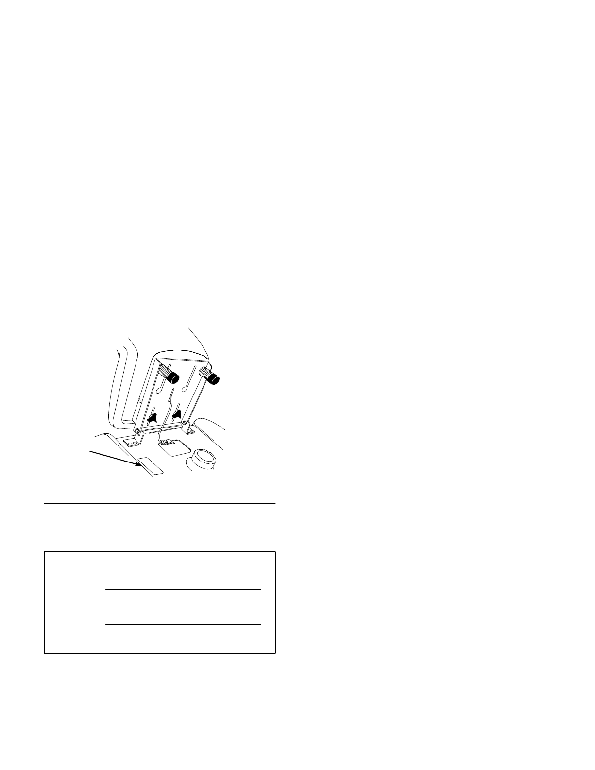
product. You will find the model and serial number
plate located in a unique place on the product as
shown below
.
Read this manual carefully to learn how to operate
and maintain your product correctly. Reading this
manual will help you and others avoid personal injury
and damage to the product. Although we design,
produce and market safe, state-of-the-art products,
you are responsible for using the product properly
and safely. You are also responsible for training
persons, who you allow to use the product, about safe
operation.
The warning system in this manual identifies
potential hazards and has special safety messages that
help you and others avoid personal injury, even death.
DANGER, WARNING and CAUTION are signal
words used to identify the level of hazard. However,
regardless of the hazard, be extremely careful.
DANGER signals an extreme hazard that will cause
serious injury or death if the recommended
precautions are not followed.
WARNING signals a hazard that may cause serious
injury or death if the recommended precautions are
not followed.
1
1. Model
For your convenience, write the product model and
serial numbers in the space below.
Model No:
Serial No.
and Serial Number Plate
(under the seat)
1202
CAUTION signals a hazard that may cause minor or
moderate injury if the recommended precautions are
not followed.
Two other words are also used to highlight
information. “Important” calls attention to special
mechanical information and “Note” emphasizes
general information worthy of special attention.
The left and right side of the machine is determined
by sitting on the seat in the normal operator’s
position.
The Toro Company – 1998
All Rights Reserved
Page 3

Contents
Page
Safety 2.
Gasoline and Oil 10
Operation 12
. . . . . . . . . . . . . . . . . . . . . . . . . . . . . . . .
Safe Operation Practices for Ride-on (riding)
Rotary Lawnmower Machines2. . . . . . . .
Safe Operating Practices 2
Sound Pressure Level 4
Sound Power Level 4
Vibration Level 4
Slope Chart 5
Symbols Glossary7. . . . . . . . . . . . . . . . . . .
Symbols Glossary8. . . . . . . . . . . . . . . . . . .
Symbols Glossary9. . . . . . . . . . . . . . . . . . .
Recommended Gasoline10. . . . . . . . . . . . . .
Stabilizer/Conditioner 11
Filling the Fuel Tank 11
Check Engine Oil Level 11
. . . . . . . . . . . . . . . . . . . . . . . . . . . . . .
Think Safety First 12
Controls 12
Key Choice Switch 12
Parking Brake 12
Starting and Stopping
the Engine 13
Operating the
Power Take Off (PTO) 14
The Safety Interlock System 15
Operating–in–Reverse 15
Indicator Control Module 17
Driving Forward or Backward 18
Stopping the Machine 18
Attachment Power Lift 19
Adjusting Dial-A-Height 19
. . . . . . . . . . . . . . . . . . . . . . . . . . .
. . . . . . . . . . . . . . . . . . . . .
. . . . . . . . . . . . . . . . . . . . . . . . .
. . . . . . . . . . . . . . . . . . . . . . . .
. . . . . . . . . . . . . . . . . . . . . . .
. . . . . . . . . . . . . . . . . . . . . . . .
. . . . . . . . . . . . . .
. . . . . . . . . . . . . . . . .
. . . . . . . . . . . . . . . . . .
. . . . . . . . . . . . . . . .
. . . . . . . . . . . . . . . . .
. . . . . . . . . . . . . . .
. . . . . . . . . . . . . . . . . . .
. . . . . . . . . . . . . . . . . . .
. . . . . . . . . . . . . .
. . . . . . . . . . .
. . . . . . . . . . . . . . . .
. . . . . . . . . . . . .
. . . . . . . . . .
. . . . . . . . . . . . . . . .
. . . . . . . . . . . . . . . .
. . . . . . . . . . . . . .
Page
Positioning the Seat 19
Headlights 20
Positioning the
Tilt Steering Wheel 20
Using the Cruise Control 20
Pushing the Machine by Hand 21
Maintenance 22
Service Interval Chart 22
Air Cleaner 23
Engine Oil 25
Spark Plug 27
Greasing and Lubrication 28
Tire Pressure 28
Brake 29
Fuel Tank 30
Fuel Filter 31
Power Lift 31
Front Wheel Toe-In 32
Transaxle Fluid 32
Fuse 33
Headlights 33
Battery 34
Wiring Diagram 37
Cleaning and Storage 39
Troubleshooting 40
. . . . . . . . . . . . . . . . . . . . . . . . .
. . . . . . . . . . . . . . . . . . . . . . . . . . . .
. . . . . . . . . . . . . . . . . . . . . . . . .
. . . . . . . . . . . . . . . . . . . . . . . . .
. . . . . . . . . . . . . . . . . . . . . . . . .
. . . . . . . . . . . . . . . . . . . . . . . .
. . . . . . . . . . . . . . . . . . . . . . . . . . . . .
. . . . . . . . . . . . . . . . . . . . . . . . . .
. . . . . . . . . . . . . . . . . . . . . . . . . .
. . . . . . . . . . . . . . . . . . . . . . . . .
. . . . . . . . . . . . . . . . . . . . . . . . . . . . . .
. . . . . . . . . . . . . . . . . . . . . . . . .
. . . . . . . . . . . . . . . . . . . . . . . . . . . .
. . . . . . . . . . . . . . . . . . . . . . . . .
. . . . . . . . . . . . . . . . . .
. . . . . . . . . . . . . . . . .
. . . . . . . . . . . . . .
. . . . . . . . . .
. . . . . . . . . . . . . . . .
. . . . . . . . . . . . . .
. . . . . . . . . . . . . . . . . .
. . . . . . . . . . . . . . . . . . . . . .
. . . . . . . . . . . . . . . . . . . . .
. . . . . . . . . . . . . . . . .
1
Page 4

Safety
Safe
Operation Practices for
Ride-on (riding) Rotary
Lawnmower Machines
This machine meets or exceeds European
Standards in effect at the time of production.
However, improper use or maintenance by the
operator or owner can result in injury. To reduce
the potential for injury, comply with these safety
instructions and always pay attention to the safety
alert
WARNING, or DANGER—“personal safety
instruction.” Failure to comply with the
instruction may result in personal injury or death.
Safe
This product is capable of amputating hands and feet
and throwing objects. Always follow all safety
instructions to avoid serious injury or death.
symbol, which means CAUTION,
Operating Practices
6. All drivers should seek and obtain professional
and practical instruction. Such instruction should
emphasize:
• the need for care and concentration when
working with ride-on machines;
• control of a ride-on machine sliding on a
slope will not be regained by the application
of the brake. The main reasons for loss of
control are:
insufficient wheel grip;
being driven too fast;
inadequate braking;
the type of machine is unsuitable for its
task;
lack of awareness of the effects of
ground conditions, especially slopes;
incorrect hitching and load distribution.
Preparation
Training
1. Read the instructions carefully. Be familiar with
the controls and the proper use of the equipment.
2. Never allow children or people unfamiliar with
these instructions to use the lawnmower. Local
regulations may restrict the age of the operator.
3. Never mow while people, especially children, or
pets are nearby.
4. Keep in mind that the operator or user is
responsible for accidents or hazards occurring to
other people or their property.
5. Do not carry passengers.
1. While mowing, always wear substantial
footwear and long trousers. Do not operate the
equipment when barefoot or wearing open
sandals.
2. Thoroughly inspect the area where the
equipment is to be used and remove all objects
which may be thrown by the machine.
3. WARNING – Fuel is highly flammable.
• Store fuel in containers specifically
designed for this purpose.
• Refuel outdoors only and do not smoke
while refuelling.
• Add fuel before starting the engine. Never
remove the cap of the fuel tank or add fuel
while the engine is running or when the
engine is hot.
2
Page 5

Safety
• If fuel is spilled, do not attempt to start the
engine but move the machine away from
the are of spillage and avoid creating any
source of ignition until petrol vapors have
dissipated.
• Replace all fuel tanks and container caps
securely.
Replace faulty silencers.
4.
5. Before using, always visually inspect to see that
the blades, blade bolts and cutter assembly are
not worn or damaged. Replace worn or damaged
blades and bolts in sets to preserve balance.
6. On multi–bladed machines, take care as rotating
one blade can cause other blades to rotate.
Operation
1. Do not operate the engine in a confined space
where dangerous carbon monoxide fumes can
collect.
2. Mow only in daylight or in good artificial light.
7. When using any attachments, never direct
discharge of material toward bystanders nor
allow anyone near the machine while in
operation.
8. Never operate the lawnmower with damaged
guards or without safety protective devices in
place.
9. Do not change the engine governor settings or
overspeed the engine. Operating the engine at
excessive speeds may increase the hazard of
personal injury.
10. Before leaving the operator’
s position:
• disengage the power take-off and lower the
attachments;
• change into neutral and set the parking
brake;
• stop the engine and remove the key.
11. Disengage drive to attachments, stop the engine,
and disconnect the spark plug wire(s) or remove
the ignition key
3. Before attempting to start the engine, disengage
all blade attachment clutches and shift into
neutral.
4. Use care when pulling loads or using heavy
equipment.
• Use only approved drawbar hitch points.
• Limit loads to those you can safely control.
• Do not turn sharply. Use care when
reversing.
• Use counterweight(s) or wheel weights
when suggested in the instruction
handbook.
5. Watch out for traffic when crossing or near
roadways.
6. Stop the blades before crossing surfaces other
than grass.
• before cleaning blockages or unclogging
chute;
• before checking, cleaning or working on the
lawnmower;
• after striking a foreign object. Inspect the
lawnmower for damage and make repairs
before restarting and operating the
equipment;
• if the machine starts to vibrate abnormally
(check immediately).
12. Disengage drive to attachments when
transporting or not in use.
13. Stop the engine and disengage drive to
attachment
• before refuelling;
• before removing the grass catcher;
3
Page 6

Safety
• before making height adjustment unless
adjustment can be made from the operator’s
position.
14. Reduce the throttle setting during engine run-out
and, if the engine is provided with a shut-off
valve, turn the fuel off at the conclusion of
mowing.
Slope Operation
1. For operation on slopes:
• Never mow side hills over 5
• Never mow uphill over 10
• Never mow downhill over 15
2. Remember there is no such thing as a “safe”
slope. Travel on grass slopes requires particular
care. To guard against overturning:
• do not stop or start suddenly when going up
or downhill;
engage clutch slowly
•
in gear, especially when travelling
downhill;
, always keep machine
4. To reduce the fire hazard, keep the engine,
silencer, battery compartment and petrol storage
area free of grass, leaves, or excessive grease.
5. Check the grass catcher frequently for wear or
deterioration.
6. Replace worn or damaged parts for safety.
7. If the fuel tank has to be drained, this should be
done outdoors.
8. On multi-bladed machines, take care as rotating
one blade can cause other blades to rotate.
9. When machine is to be parked, stored or left
unattended, lower the cutting means unless a
positive mechanical lock is used.
Sound
This unit has an equivalent continuous A-weighted
sound pressure at the operator ear of: 90 dB(A), based
on measurements of identical machines per Directive
84/538/EEC and amendments.
Pressure Level
• machine speeds should be kept low on
slopes and during tight turns;
• stay alert for bumps and hollows and other
hidden hazards;
• never mow across the face of the slope,
unless the lawnmower is designed for this
purpose.
Maintenance and storage
1. Keep all nuts, bolts and screws tight to be sure
the equipment is in safe working condition.
2. Never store the equipment with fuel in the tank
inside a building where fumes may reach an
open flame or spark.
3. Allow the engine to cool before storing in any
enclosure.
Sound
This unit has a sound power level of: 105 Lwa, based
on measurements of identical machines per
procedures outlined in Directive 84/538/EEC and
amendments.
Vibration
This unit has a maximum hand-arm vibration level of
3.0 m/s2 and whole body vibration level of 0.3 m/s2,
based on measurements of identical machines per EN
1033 and EN 1032.
Power Level
Level
4
Page 7
Safety
Slope
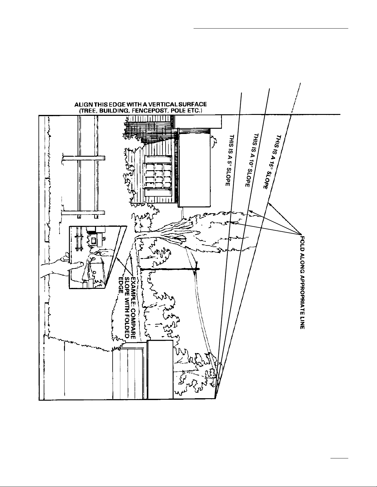
Read all safety instructions on pages 2–NO TAG.
Chart
5
Page 8

6
Page 9
Safety
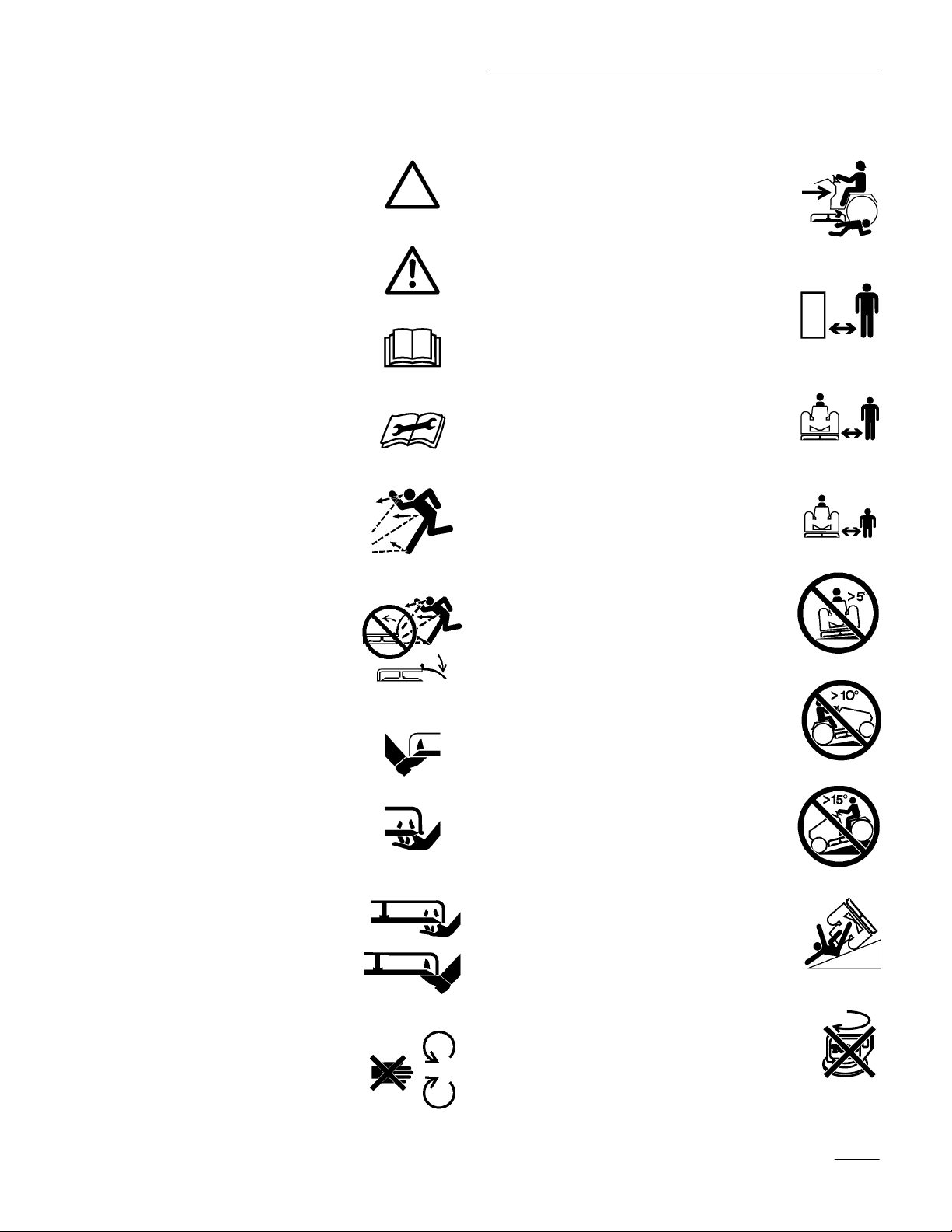
Symbols
Safety alert symbol
Safety alert symbol
Read operator’s manual
Consult Technical Manual for
proper service procedures
Thrown or flying objects–
Whole body exposure
Glossary
Dismemberment–Mower
in rearward motion
Stay a safe distance
from the machine
Stay a safe distance
from the mower
Keep children a safe distance
from machine
Thrown or flying objects–
Rotary side-mounted mower
Keep deflector shield in place
Severing toes or foot–
mower blade
Severing fingers or hand–
mower blade
Rotating blade can cut off
toes or fingers. Stay clear
of blade as long as engine
is running
Do not open or
remove safety shields
while engine is running
Machine rollover
side hill
.
Machine rollover
up hill
Machine rollover
down hill
Machine rollover
Operating in reverse not
allowed unless deactivated
by Key Choice switch
7
Page 10
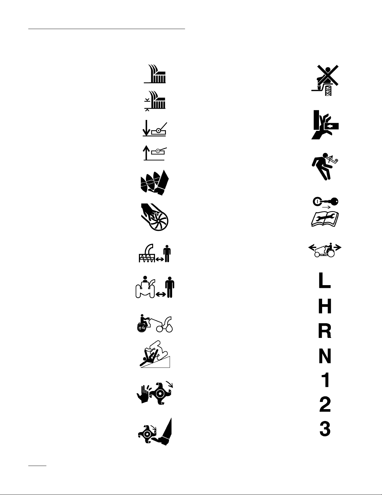
Safety
Symbols Glossary
Cutting element–
basic symbol
Cutting element–
height adjustment
Cutting unit–lower
Cutting unit-raised
Cutting or entanglement
of foot–Rotating auger
Severing of fingers or hand–
impeller blade
Keep a safe distance from
snowthrower
Riding on this machine is allowed
only on a passenger seat & only
if the driver
Crushing of fingers
or hands–Force applied
from side
Kickback or upward
motion–Stored energy
Shut off engine & remove key
before performing maintenance
or repair work
Machine travel direction–
combined
’s view is not hindered
Stay a safe distance
from the snowthrower
T
ractors must be equipped
with 45kg rear wheel weight
with this attachment installed
Machine rollover
ROPS snowthrower
Severing of hand–
Rotating knives
Severing of foot–
Rotating knives
Low
High
Reverse
Neutral
First gear
Second gear
Third gear up to
maximum # of
forward gears
8
Page 11
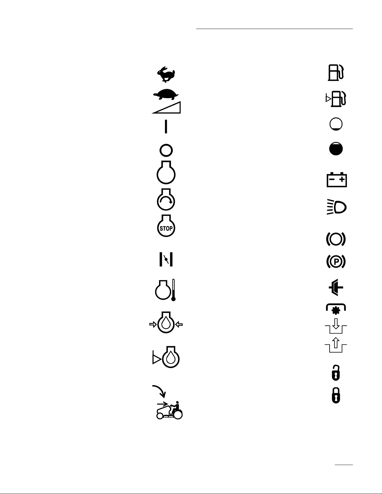
Symbols Glossary
Safety
Fast
Slow
Decreasing/Increasing
On/Run
Off/Stop
Engine
Engine start
Engine stop
Fuel
Fuel level
olume empty
V
V
olume full
Battery charging conditin
Head lights–
Main/high beam
Brake system
Choke
Engine temperature
Engine lubricating
oil pressure
Engine lubricating oil level
Key Choice Switch
Parking brake
Clutch
PT
O (Power T
Engage
Disengage
Unlock
Lock
ake Off)
9
Page 12

Gasoline and Oil
Recommended
Use UNLEADED Regular Gasoline suitable for
automotive use (85 pump octane minimum). Leaded
regular gasoline may be used if unleaded regular is
not available.
IMPORTANT: Never use methanol, gasoline
containing methanol, or gasohol containing
more than 10% ethanol because the fuel
system could be damaged. Do not mix oil with
gasoline.
POTENTIAL HAZARD
Gasoline
• In certain conditions gasoline is extremely
flammable and highly explosive.
WHAT CAN HAPPEN
• A fire or explosion from gasoline can burn
you, others, and cause property damage.
HOW TO AV
OID THE HAZARD
• Use a funnel and fill the fuel tank outdoors,
in an open area, when the engine is cold.
Wipe up any gasoline that spills.
• Do not fill the fuel tank completely full.
Add gasoline to the fuel tank until the level
is 1/4” to 1/2” (6 mm to 13 mm) below the
bottom of the filler neck. This empty space
in the tank allows gasoline to expand.
• Never smoke when handling gasoline, and
stay away from an open flame or where
gasoline fumes may be ignited by a spark.
• Store gasoline in an approved container
and keep it out of the reach of children.
Never buy more than a 30-day supply of
gasoline.
POTENTIAL HAZARD
• In certain conditions gasoline is extremely
flammable and highly explosive.
WHAT CAN HAPPEN
• A fire or explosion from gasoline can burn
you, others, and cause property damage.
HOW TO AV
OID THE HAZARD
• Always place gasoline containers on the
ground away from your vehicle before
filling.
• Do not fill gasoline containers inside a
vehicle or on a truck or trailer bed because
interior carpets or plastic truck bed liners
may insulate the container and slow the
loss of any static charge.
• When practical, r
equipment from the truck or trailer and
refuel the equipment with its wheels on the
ground.
emove gas–power
ed
• If this is not possible, then refuel such
equipment on a truck or trailer from a
portable container, rather than from a
gasoline dispenser nozzle.
• If a gasoline dispenser nozzle must be used,
keep the nozzle in contact with the rim of
the fuel tank or container opening at all
times until fueling is complete.
10
Page 13

Gasoline and Oil
Stabilizer/Conditioner
Add the correct amount of gas stabilizer/conditioner
to the gas. Using a stabilizer/conditioner in the
machine:
• Keeps gasoline fresh during storage of 90 days
or less. For longer storage it is recommended
that the fuel tank be drained.
• Cleans the engine while it runs
• Eliminates gum-like buildup in the fuel system,
which causes hard starting
IMPORTANT: Never use fuel additives
containing methanol or ethanol.
Filling
1. Shut the engine off and set the parking brake.
2. Clean around each fuel tank cap and remove the
3. Install fuel tank caps securely. Wipe up any
4. Fuel gauge is located in right side tank.
Check
Before you start the engine and use the machine,
check the oil level in the engine crankcase; refer to
Checking Oil Level, page 25.
the Fuel T
cap. Add unleaded regular gasoline to both fuel
tanks, until the level is 1/4 to 1/2 inch (6 mm to
13 mm) below the bottom of the filler neck. This
space in the tank allows gasoline to expand. Do
not fill the fuel tanks completely full.
gasoline that may have spilled.
ank
Engine Oil Level
11
Page 14
Operation
Think
Safety First
Please carefully read all the safety instructions on
pages 2–9. Knowing this information could help you,
your family, pets or bystanders avoid injury.
Controls
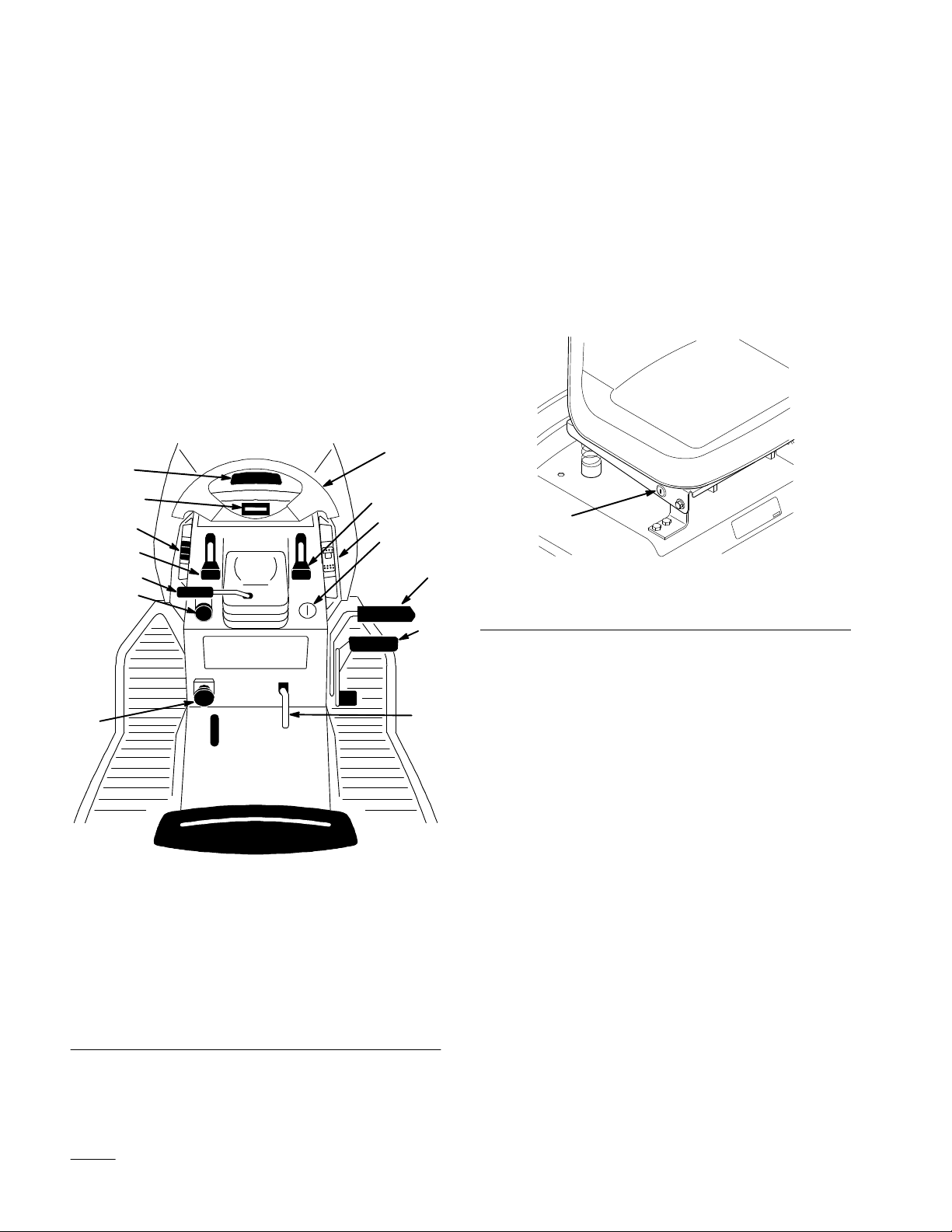
Become familiar with all the controls (Fig. 1) before
you start the engine and operate the machine.
1
13
10
11
7
12
8
6
9
2
Key
Choice Switch
A turn and release switch used for deactivating the
“Operating–In–Reverse” interlock feature. Located
on the seat bracket on the right hand just below the
seat (Fig. 2).
1
m–4220
3
1. “Key
5
Choice” switch
Figure 2
14
1. Steering
2.
3.
4.
5.
6.
7.
8.
wheel
Ignition switch
Brake pedal
Parking brake lever
Ground speed selector
Throttle lever
Choke lever
Power take of
f (PT
O)
Figure 1
9.
Cruise control switch
10.
Indicator control
module/Hourmeter
11.
Attachment lift switch
12. T
ilt wheel lever
13.
Hood opening
14.
Dial-a-height knob
Parking Brake
4
Always set the parking brake when you stop the
machine or leave it unattended.
While the ignition key is in the “RUN” or “LIGHTS”
positions and the Parking Brake is engaged, the light,
in the Indicator Module, will be lit.
2332
Setting the Parking Brake
1. Push the brake pedal (Fig. 3) down and hold it in
the depressed position.
2. Lift the parking brake lever (Fig. 3) up and
gradually take your foot off the brake pedal. The
brake pedal should stay in the depressed (locked)
position.
12
Page 15
Operation
Releasing the Parking Brake
1. Push down on the brake pedal (Fig. 3). The
parking brake lever should release.
2. Gradually release the brake pedal.
Figure 3
1. Brake
pedal
2.
Parking brake lever
2
2333
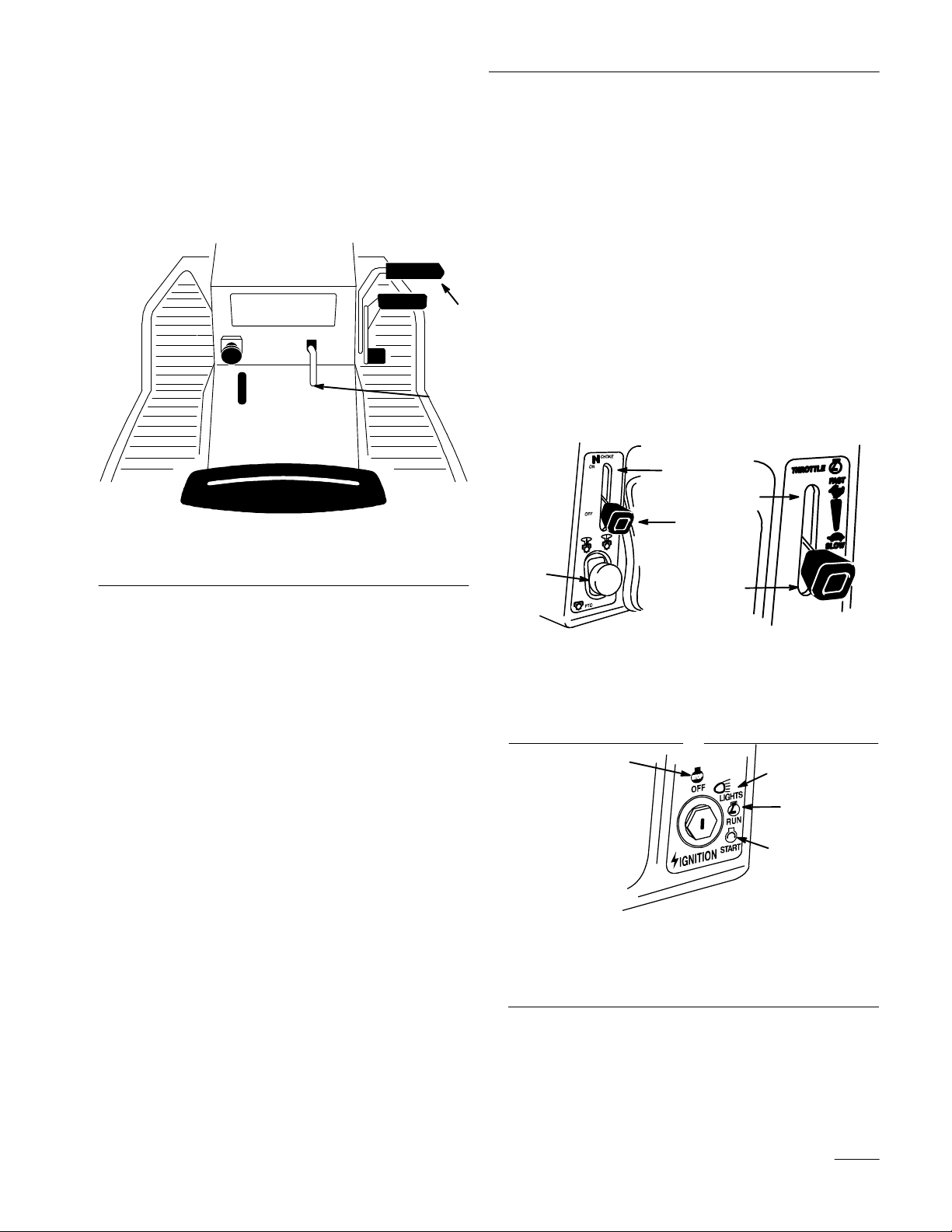
5. Move throttle lever to “FAST” (Fig. 5).
6. Turn the ignition key clockwise and hold it in
the “START” position (Fig. 6). When the engine
starts, release the key.
IMPORTANT: If the engine does not start
after 30 seconds of continuous cranking, turn
the ignition key to “OFF” and let the starter
motor cool; refer to Troubleshooting, page 40.
1
7. After the engine starts, move the choke lever to
“OFF” (Fig. 5). If the engine stalls or hesitates,
move the choke lever back to “ON” for a few
seconds. Then move the throttle lever to desired
setting. Repeat this as required.
2
1
3
1
2
Starting
and Stopping
the Engine
Starting
1. Sit down on the seat.
2. Set the parking brake; refer to Setting the
Parking Brake, page 12.
Note: The engine will not start unless you set
the parking brake or fully depress the
brake pedal.
3. Push the PTO (power take off) to “OFF”
(Fig. 4).
4. Move the choke lever to “ON” (Fig. 4).
Note: An engine that has been running and is
warm may not require step 4.
Figure 4
1. PTO—Off
2. Choke–On
3. Choke–Off
1. Off
2. Lights
1206
Figure 5
1. Fast
2. Slow
1
Figure 6
3. Run
4. Start
2
3
4
1207
1208
13
Page 16
Operation
Stopping
1. Move the throttle lever to “SLOW” (Fig. 5).
2. Turn the ignition key to “OFF” (Fig. 6).
Note: If the engine has been working hard or
is hot, let it idle for a minute before
turning the ignition key “OFF.” This
helps cool the engine before it is
stopped. In an emergency, the engine
may be stopped by turning the ignition
key to “OFF.”
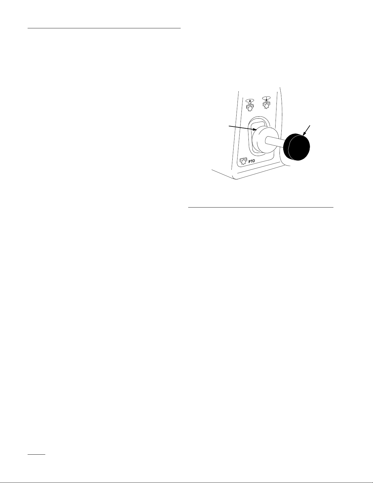
Operating
Power T
The power take off (PT
power to the electric clutch.
While the ignition key is in “RUN” or “LIGHTS”
position and the power take off (PTO) is engaged
“ON”, the PTO light, in the Indicator Module, will be
“ON”. When this light is “ON” it is a reminder; the
starter will not crank and to turn the off PTO before
getting off.
the
ake Off (PT
O) engages and disengages
O)
Engaging the Power Take Off (PTO)
1. Depress the brake pedal to stop the machine.
2. Pull the power take off (PTO) to “ON” (Fig. 7).
2
1
1206
Figure 7
1. Off-Disengaged 2. On-Engaged
Disengaging the Power Take Off (PTO)
1. Depress the brake pedal to stop the machine.
2. Push the power take off (PTO) to “OFF”
(Fig. 7).
14
Page 17

Operation
The
Safety Interlock System
Understanding the Safety Interlock
System
The safety interlock system is designed to prevent the
engine from starting unless:
• You are sitting on the seat
• The brake pedal is depressed
• The power take off (PTO) is “OFF”
The safety interlock system is designed to stop the
engine if:
• You rise from the seat when the brake pedal is
released
• You rise from the seat when the power take off
(PTO) is “ON”or gear selector is not in “N”
neutral.
The safety interlock system is designed to stop the
power take off (PTO) if:
• You shift into reverse with the power take off
(PTO) engaged.
Operating–in–Reverse
An interlock feature is provided that prevents the
Power Take Off (PTO) from operating while the
tractor is traveling in reverse. If the unit is shifted
into reverse while the mower blade or other PTO
driven attachment is engaged, the PTO will stop.
Do not mow while backing up unless it is
absolutely necessary
reverse gear or use other PTO driven attachments
(such as a snowthrower or tiller), this
operating–in–reverse interlock feature may be
temporarily deactivated.
. If you need to mow while in
Before deactivating this feature, be sure there are no
children present on or near the property where you are
using the tractor, and that none are likely to appear
while you are mowing or operating an attachment.
Be extra observant after you have chosen to
deactivate the interlock feature because the sound of
the tractor’s engine might prevent you from being
aware that a child or a bystander has entered the area
where you are operating the tractor.
If you are certain that you can safely mow in reverse
or operate an attachment, deactivate the
operating–in–reverse interlock feature by turning the
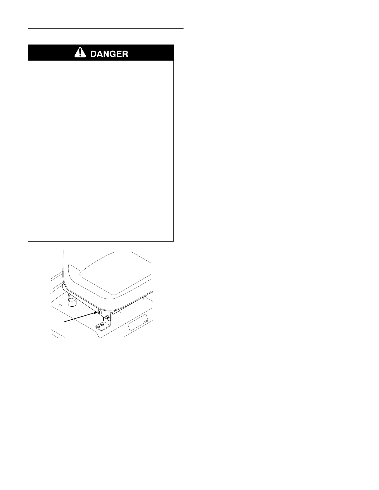
“Key Choice” switch (Fig. 8), located on the seat
bracket on the right hand side just below the seat,
after engaging the blade (PTO). A red light on the
front console (Fig. 9) will turn on as a reminder that
the operating–in–reverse interlock has been
deactivated. Once the interlock is deactivated it stays
in this mode––with your mower blade or PTO–driven
attachment operating whenever you back up–– and
the console light stays on until either the blade (PTO)
is disengaged, or the engine is turned off.
Note: Do not insert the “Key Choice” key
unless it is absolutely necessary to
mow in reverse or operate an
attachment. The “Key Choice” key
should also be removed from the unit
if it will be operated by someone other
than a responsible, experienced
operator. This will prevent the unit
from operating in reverse with the
mower blade or other PTO attachment
engaged. Always remove both the
ignition and the “Key Choice” keys
and put them in a safe place out of the
reach of children when leaving the unit
unattended.
15
Page 18
Operation
POTENTIAL HAZARD
• A child or bystander could be backed over
by a riding mower with its blade(s)
engaged.
1. Set the parking brake. Move the power take off
(PTO) to “ON”. Now turn the ignition key to
“START”; the engine should not crank.
2. Push the power take off (PTO) to “OFF” and
release the parking brake. Now turn the ignition
key to “START”; the engine should not crank.
WHAT CAN HAPPEN
• Blade contact will cause serious personal
injury or death.
HOW TO AV
• Do not mow in r
OID THE HAZARD
everse unless absolutely
necessary.
• Always look backward and down before
backing up.
• Use “Key Choice” switch only if you are
certain no children or other bystanders will
appear in the mowing area.
•
Always r
Choice” keys and put them in a safe place
out of the reach of children or unauthorized
users when leaving the unit unattended.
emove both the ignition and “Key
3. Set the parking brake and move the power take
off (PTO) to “OFF”(On gear drive models the
speed selector lever must be in “N” neutral).
Now start the engine. While the engine is
running, release the parking brake and rise
slightly from the seat; the engine should stop.
4. With the parking brake released, turn the ignition
key to RUN without starting the engine. Pull the
PTO switch to ON. You should hear an audible
click indicating the PTO is activated and the
PTO light will illuminate. Move the foot pedal
to reverse. You should hear an audible click
indicating the PTO is deactivated and the PTO
light should turn off.
5. With the parking brake released, turn the ignition
key to RUN without starting the engine. Pull the
PTO switch to ON. You should hear an audible
click indicating the PTO is activated and the
PTO light will illuminate. Move the foot pedal
to reverse. You should hear an audible click
indicating the PTO is deactivated and the PTO
light should turn off.
1
m–4220
Figure 8
1. “Key
Choice” switch
Testing the Safety Interlock System
Test the safety interlock system before you use the
machine each time. If the safety system does not
operate as described below, have an Authorized
Service Dealer repair the safety system immediately.
16
6. With the parking brake released, turn the ignition
switch to RUN without starting the engine. Pull
the PTO switch to ON. Turn the “Key Choice”
key and release. The Operating–in–Reverse
warning light should illuminate. Move the foot
pedal to reverse. The PTO and PTO light on the
dash should remain on. Push the PTO switch to
OFF. The PTO light and the
Operating–in–Reverse warning light should turn
off.
Page 19
Operation
Indicator
Control Module
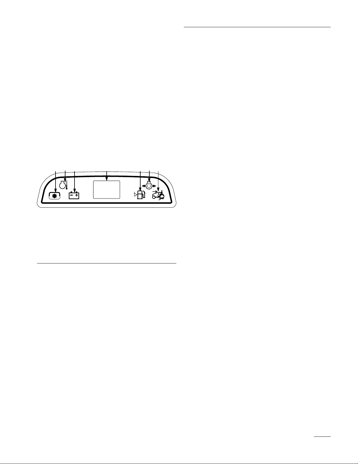
The indicator control module (Fig. 9) contains lights
for:
• Operating–in–Reverse
• Power take off (PTO)
• Battery
• Hourmeter
• Oil pressure
• Fuel level
7531 42 6
Figure 9
1. Power
2. Temperature
3. Battery
4. Hourmeter
take of
f (PT
O)
5.
Fuel Level
6. Oil
7. Operating–in–Reverse
PTO (Power Take Off)
The PTO (power take off) light will be “ON” when
the key is in the “RUN” or “LIGHTS” positions and
the PTO (power take off) is engaged “ON”. When
this light is “ON” it is a reminder; the starter will not
crank and turn off the PTO before getting off.
Hourmeter
The hourmeter records the number of hours the
engine has operated (Fig. 9). It is turned on when the
ignition switch is in the “RUN” or “LIGHTS”
positions. Use the times for scheduling regular
maintenance.
Battery
The battery light will be “ON” when the key is in the
“RUN” or “LIGHTS” positions if the battery voltage
is below 12.6 volts or when the engine is running and
the alternator output is above 14.8 volts. When this
light comes on it is important to have your battery
and electrical system checked and the problem
corrected.
Fuel Level
Following are the conditions when indicator lights
will be “ON”. At other times the lights should be off.
Operating–in–Reverse
The Operating–in–Reverse light will illuminate
whenever the “key choice” switch is used to
deactivate the operating–in–reverse interlock. It is a
reminder that the interlock system is deactivated.
The light goes out whenever the power take off (PTO)
is disengaged or the engine is shut off.
The fuel level light will be “ON” when the key is in
the “RUN” or “LIGHTS” positions and the fuel level
is low, approximately one pint remaining.
Oil
The oil light will be “ON” when the key is in the
“RUN” or “LIGHTS” positions and the engine is not
running, after the engine is started the light should go
out. When the engine is running if the oil pressure
drops below a safe operating level the light comes
“ON”. When the light comes on while the engine is
running, Stop engine immediately and correct the
cause of low oil pressure.
17
Page 20
Operation
Driving
The throttle control regulates the engine speed as
measured in rpm (revolutions per minute). Place the
throttle control in the “FAST” position for best
performance.
Forward or Backward
Temperature
The temperature light will be “ON” when the key is
in the “RUN” or “LIGHTS” positions and the engine
temperature exceeds proper operating limits. Stop
engine immediately and correct the cause of high
temperature.
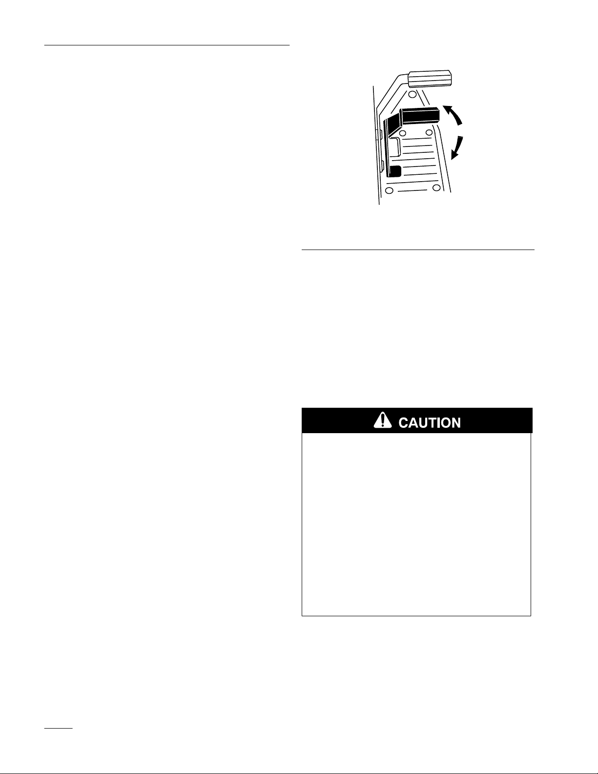
To go forward or backward, release the parking brake:
refer to Releasing the Parking Brake, page 13. Place
your foot on the traction control pedal and slowly
press on the top of the traction control pedal to move
forward or on the bottom of the traction control pedal
to move backward (Fig. 10). The farther you move
the traction control pedal in either direction, the faster
the machine will move in that direction.
Note: For reverse motion, with the PTO
engaged, the operating–in–reverse
interlock must be deactivated by the
“Key Choice” switch located on the
seat bracket on the right hand side just
below the seat.
To slow down, release the pressure on the traction
control pedal.
IMPORTANT: To avoid transmission
damage, always release the parking brake
before moving the traction control pedal.
1
2
1210
Figure 10
1. Forward 2. Backward
Stopping
To stop the machine, release the traction control
pedal, disengage the power take off (PTO), and turn
the ignition key to “OFF” to stop the engine. Also set
the parking brake if you leave the machine
unattended; refer to Setting the Parking Brake,
page 12. Remember to remove the key from the
ignition switch.
POTENTIAL HAZARD
the Machine
• Someone could move or attempt to operate
the tractor while it is unattended.
WHAT CAN HAPPEN
• Children or bystanders may be injured if
they use the tractor.
HOW TO AV
•
Always r
Choice” keys and set the parking brake
when leaving the machine unattended, even
if just for a few minutes.
OID THE HAZARD
emove the ignition and “Key
18
Page 21
Operation
Attachment
Power Lift
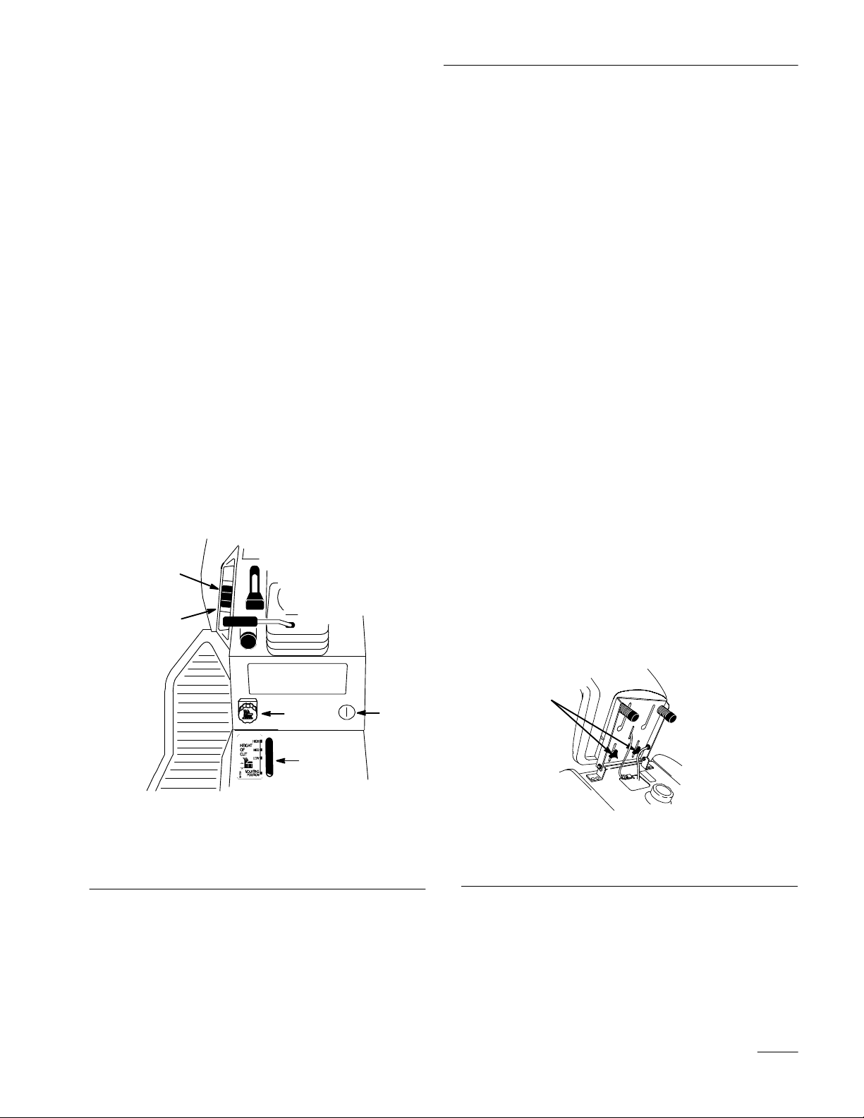
The attachment power lift (Fig. 11) is used to raise
and lower attachments.
Raising Attachments
1. Turn key to the “ON” or “RUN” position
(Fig. 11).
2. Push the lift switch in the “UP” direction to raise
the attachment lift (Fig. 11). This will lift and
hold the attachment in the up, or raised position.
Lowering Attachments
1. Turn key to the “ON” or “RUN” position
(Fig. 11).
2. Push the lift switch in the “DOWN” direction to
lower the attachment lift (Fig. 11). This will
lower the attachment lift.
Adjusting
Dial-A-Height
The Dial-A-Height control (Fig. 11) is used to limit
the downward travel of the attachment. The
Dial-A-Height knob is rotated to change the location
of this stop, up or down.
1. Raise the attachment lift lever: Refer to Raising
Attachments. In the raised position the
Dial-A-Height knob (Fig. 11) can be rotated to
change the stop location. Turn clockwise to raise
and counterclockwise to lower the height of the
attachment.
2. The Dial-A-Height indicator (Fig. 11) will show
the change, high to low, in attachment lift height
as adjustment is made.
Positioning
the Seat
The seat can move forward and backward. Position
the seat where you have the best control of the
machine and are most comfortable.
1. Key
2. Lift
switch UP
3.
Lift switch DOWN
2
1.
Raise the seat and loosen the adjustment knobs
(Fig. 12).
3
2. Slide the seat to the desired position and tighten
the knobs.
1
1
2266
Figure 12
1. Adjustment
knob
Figure 1
4
5
1
4.
Dial-A-Height knob
5.
Dial-A-Height indicator
19
Page 22
Operation
Headlights
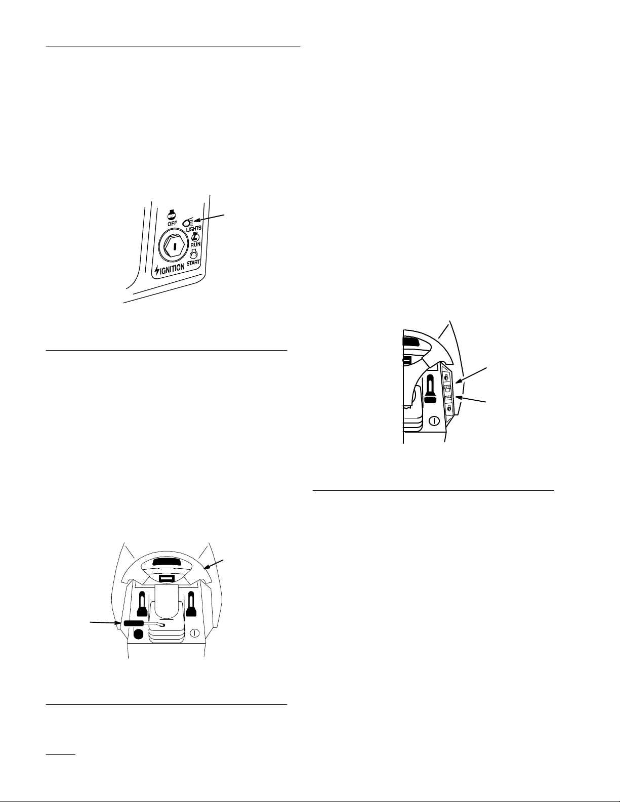
The headlights are turned on with a separate position,
“LIGHTS”, of the ignition switch (Fig. 13). The
lights are on while the ignition switch is in the
“LIGHTS” position even with the engine off.
Remove the key when the machine is left unattended
so lights can not be turned on discharging the battery.
1
1208
Figure 13
1. Lights
Using
the Cruise Control
A three position switch, located on the dash (Fig.15),
with the functions of: Lock–Set (spring loaded), On
and Unlock–Off controls the engagement. Cruise
control maintains the traction control position without
foot pressure. Cruise control is intended for operation
in the forward direction only. Do not use cruise
control in reverse.
Engaging the Cruise Control
1. Begin driving tractor: Refer to Driving Forward
or Backward, Page 18. While holding your foot
steady on the traction control, push the cruise
control switch (Fig. 15) to the “Lock–Set”
position.
1
Positioning
T
ilt Steering Wheel
the
The steering wheel has four tilt locations. Position the
steering wheel where you have the best control of the
machine and are most comfortable.
1. Lift the tilt lever to release the lock (Fig. 14).
2. Move the steering wheel to a comfortable
position; then release the lever to lock.
2
1
1203b
Figure 14
1. Tilt
lever
2.
Steering wheel
2
1238
Figure 15
1. Lock–Set 2. Unlock–Off
2. This locks the traction control in position and
your foot can then be removed from the traction
control. A constant ground speed will be
maintained.
Disengaging the Cruise Control
1. While holding your foot steady on the traction
control, move the cruise control switch (Fig. 15)
to the “Unlock–Off” position.
2. This unlocks the traction control and your foot
then operates the traction control.
3. For quick stops, just press on the brake pedal.
This automatically disengages the cruise control
and applies the brake at the same time.
20
Page 23
Operation
Pushing
the Machine by Hand
IMPORTANT: Always push the machine by
hand. Never tow the machine because
transaxle damage may occur.
To Push the Machine
1. Disengage the power take off (PTO) and turn the
ignition key to “OFF” to stop the engine.
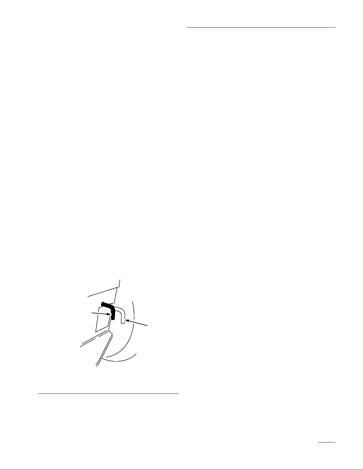
2. Move the drive control rod to the “PUSH”
position. This disengages the drive system and
allows the wheels to turn freely (Fig. 16).
IMPORTANT: Drive control rod moves to the
“OPERATE” position when the brake is
applied.
To Operate the Machine
1. Apply the brake, this moves the drive control rod
to “OPERATE” and engages the drive system, or
move the drive control rod to the “OPERATE”
position (Fig. 16).
Note: The machine will not drive unless the
drive control rod is in the “OPERATE”
position.
1
Figure 16
1. Operate
position
2.
Push position
2
1209
21
Page 24

Maintenance
Service
Service
Oil—check level
Oil—change* Initial X
Oil Filter—change* (200 hours, every
other oil change or yearly)
Safety System—check
Brake—check X X X X
Chassis—grease* X X
Foam Air Cleaner—service*
Paper Air Cleaner—replace*
Spark Plug(s)—check 200 hours
Belts—check for wear/cracks
Gasoline—drain X
Engine—clean outside
Chipped Surfaces—paint
Battery—check electrolyte
Battery—charge, disconnect cables
Fuel Filter—replace
T
ires—check pressure
Front Wheels–check toe-in
Power Lift–check fluid
T
ransaxle Fluid–check level
Interval Chart
Operation
Each
Use5Hours25Hours50Hours
X
X X
X X
X X
X X X
X X X X
X X X
X X
X X X
100
Hours
Storage
Service
X X
X X
X X
X
X
X X
X X X
Spring
Service
*
More often in dusty
22
, dirty conditions
Page 25
POTENTIAL HAZARD
• If you leave the key in the ignition switch, someone could start the engine.
WHAT CAN HAPPEN
• Accidental starting of the engine could seriously injure you or other bystanders.
Maintenance
HOW TO AV
OID THE HAZARD
• Remove the key from the ignition switch and pull the wire(s) off the spark plug(s)
before you do any maintenance. Also push the wire(s) aside so it does not
accidentally contact the spark plug(s).
Air
Cleaner
Service Interval/Specification
Foam Element: Clean and re-oil after every 25
operating hours, or yearly, whichever occurs first.
Paper Element: Replace after every 100 operating
hours or yearly, whichever occurs first.
Note: Service the air cleaner more frequently
(every few hours) if operating
conditions are extremely dusty or
sandy.
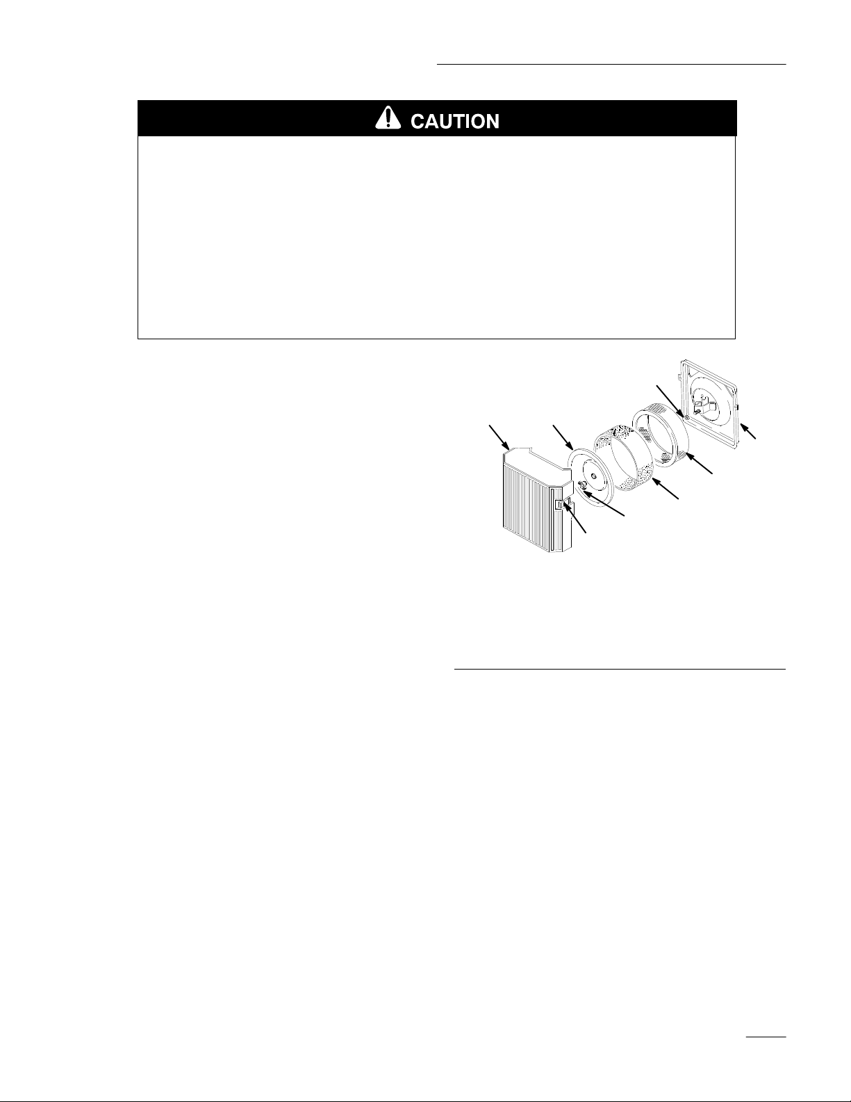
Removing the Foam and Paper Elements
1
1. Air
cleaner cover
2. Latches
3.
Cover nut
4. Cover
7
4
8
6
5
3
2
Figure 17
5.
6.
7.
8.
Foam element
Paper element
Rubber seal
Air cleaner base
1213
1. Disengage the power take off (PTO), set the
parking brake, and turn the ignition key to
“OFF” to stop the engine. Remove the key.
2. Open the hood.
3. Clean around the air cleaner to prevent dirt from
getting into the engine and causing damage.
Unhook latches and remove the air cleaner cover
(Fig. 17).
4. Carefully slide the foam element off the paper
element (Fig. 17).
5. Unscrew the cover nut and remove the cover and
paper element (Fig. 17).
23
Page 26
Maintenance
Cleaning the Foam and Paper Elements
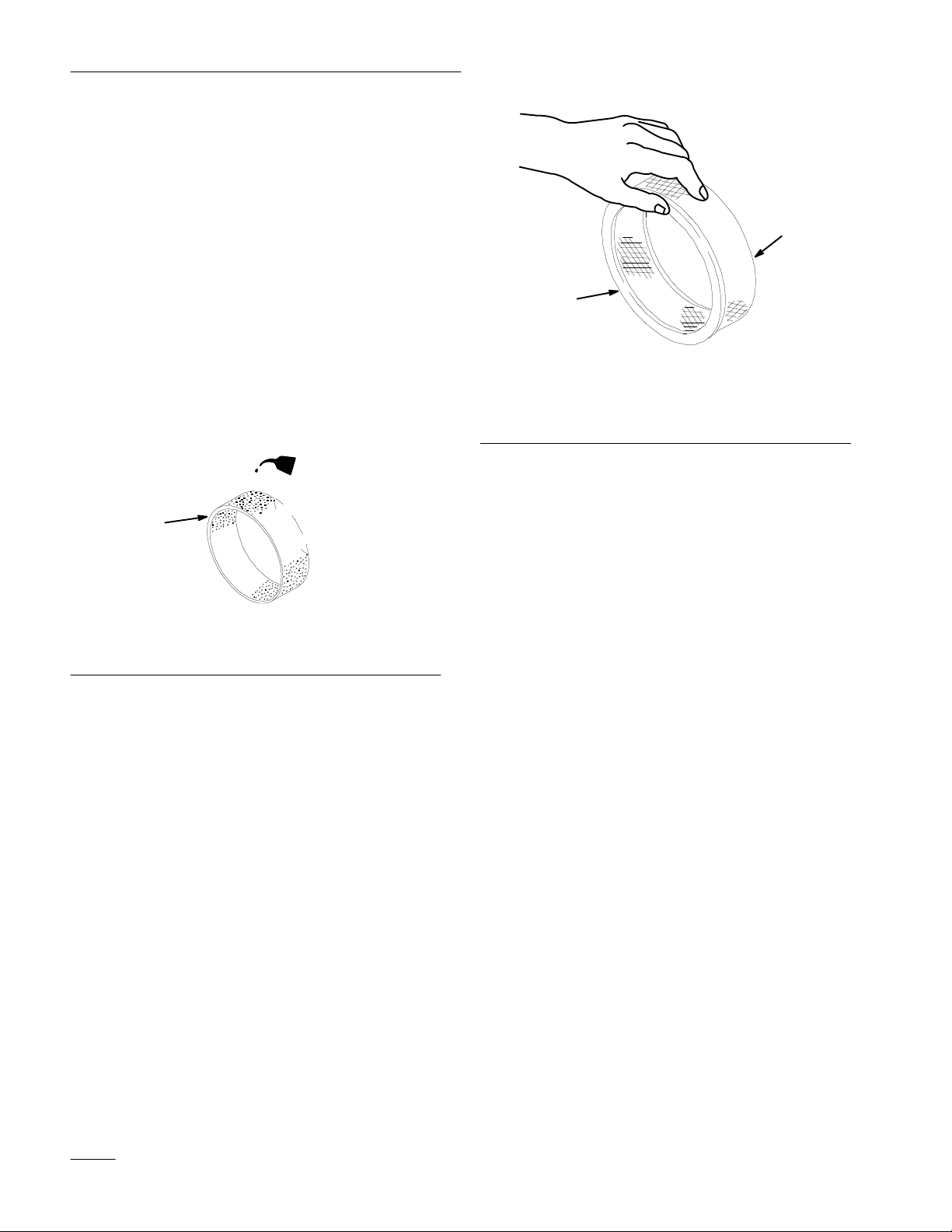
1. Foam Element
A. Wash the foam element in liquid soap and
warm water. When the element is clean,
rinse it thoroughly.
B. Dry the element by squeezing it in a clean
cloth.
C. Put one or two ounces of oil on the element
(Fig. 18). Squeeze the element to distribute
the oil.
IMPORTANT: Replace the foam element if it
is torn or worn.
2
1
2
1213
Figure 19
1. Paper
element
2.
Rubber seal
Installing the Foam and Paper Elements
1
Figure 18
1. Foam
element
2. Oil
2. Paper Element
A. Lightly tap the element on a flat surface to
remove dust and dirt (Fig. 19).
B. Inspect the element for tears, an oily film,
and damage to the rubber seal.
IMPORTANT: Never clean the paper element
with pressurized air or liquids, such as
solvent, gas, or kerosene. Replace the paper
element if it is damaged or cannot be cleaned
thoroughly.
1213
IMPORTANT: To prevent engine damage,
always operate the engine with the complete
foam and paper air cleaner assembly
installed.
1. Carefully slide the foam element onto the paper
air cleaner element (Fig. 17).
2. Slide the air cleaner assembly and cover onto the
long rod. Now screw the cover nut finger-tight
against the cover (Fig. 17).
Note: Make sure the rubber seal is flat
against the air cleaner base and cover.
3. Install the air cleaner cover and hook latches
(Fig. 17).
4. Close the hood.
24
Page 27
Maintenance
Engine
Oil
Service Interval/Specification
Change oil:
• After the first 5 operating hours.
• After every 100 operating hours.
Note: Change oil more frequently when
operating conditions are extremely
dusty or sandy.
Oil Type: Detergent oil (API service SF or SG)
Crankcase Capacity: w/filter, 4 pints (1.9 l)
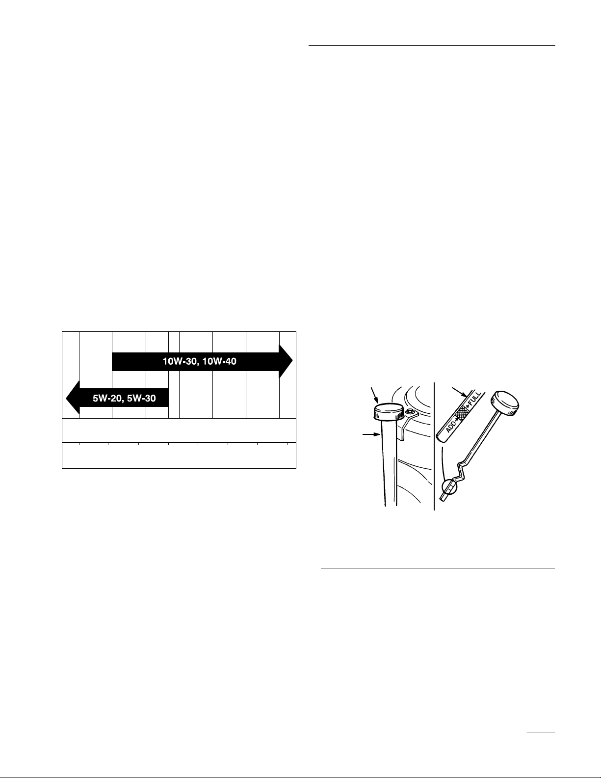
Viscosity: See table below
USE THESE SAE VISCOSITY OILS
Checking Oil Level
1. Park the machine on a level surface, disengage
the power take off (PTO), set the parking brake,
and turn the ignition key to “OFF” to stop the
engine. Remove the key.
2. Open the hood.
3. Clean around the oil dipstick (Fig. 20) so dirt
cannot fall into the filler hole and damage the
engine.
4. Unscrew the oil dipstick and wipe the metal end
clean (Fig. 20).
5. Slide the oil dipstick fully into the filler tube, do
not thread onto tube (Fig. 20). Pull the dipstick
out and look at the metal end. If oil level is low,
slowly pour only enough oil into the filler tube
to raise the level to the “FULL” mark.
IMPORTANT: Do not overfill the crankcase
with oil because the engine may be damaged.
–20 0 20
°
F
–30°–20 –10
C
40 60
32
01020
80 100
30 40
1. Oil
2.
Metal end
1
3
dipstick
2
Figure 20
3.
Filler tube
25
Page 28
Maintenance
Changing/Draining Oil
1. Start the engine and let it run five minutes. This
warms the oil so it drains better.
2. Park the machine so that the drain side is slightly
lower than the opposite side to assure the oil
drains completely. Then disengage the power
take off (PTO), set the parking brake, and turn
the ignition key to “OFF” to stop the engine.
Remove the key.
3. Open the hood.
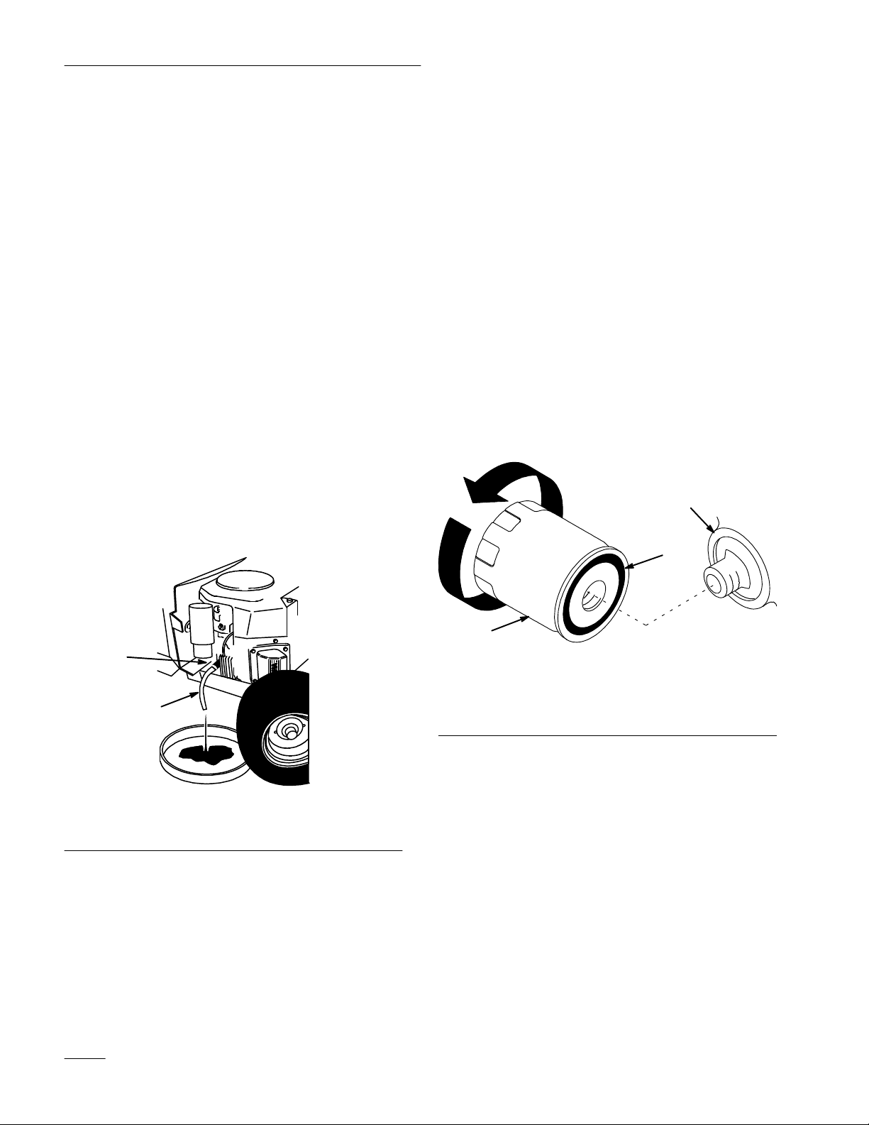
4. Slide a piece of hose over oil drain to direct oil.
5. Place a pan below the oil drain. Open the drain
by turning counterclockwise, 1/8 turn. and pull
out (Fig. 21).
6. When oil has drained completely, close the drain
by pushing in and turning clockwise, 1/8 turn.
Note: Dispose of the used oil at a certified
recycling center.
Change Oil Filter
Service Interval/Specification
Replace the oil filter every 200 hours or every other
oil change.
Note: Change oil filter more frequently when
operating conditions are extremely
dusty or sandy.
1. Drain the oil from the engine; refer to
Changing/Draining Oil, page 26.
2. Remove the old filter and wipe the filter adapter
(Fig. 22) gasket surface.
3. Apply a thin coat of new oil to the rubber gasket
on the replacement filter (Fig. 22).
3
2
1
2
1241
Figure 21
1. Oil
drain
2. Hose
7. Slowly pour approximately 80% of the specified
amount of oil into the filler tube (Fig. 20). Now
check the oil level; refer to Checking Oil Level,
page 25. Slowly add additional oil to bring to
“FULL” mark on dipstick.
1
Figure 22
1. Oil
filter
2. Gasket
3. Adapter
4. Install the replacement oil filter to the filter
adapter. Turn the oil filter clockwise until the
rubber gasket contacts the filter adapter, then
tighten the filter an additional 1/2 turn (Fig. 22).
5. Fill the crankcase with the proper type of new
oil; refer to Changing/Draining Oil, page 26.
1256
26
Page 29
Maintenance
Spark
Plug
Service Interval/Specification
Check the spark plug(s) after every 200 operating
hours. Make sure the air gap between the center and
side electrodes is correct before installing the spark
plug. Use a spark plug wrench for removing and
installing the spark plug(s) and a gapping tool/feeler
gauge to check and adjust the air gap.
Type: Champion RC–12YC (or equivalent)
Air Gap: 0.040” (1.02 mm)
Removing the Spark Plug(s)
1. Disengage the power take off (PTO), set the
parking brake, and turn the ignition key to
“OFF” to stop the engine. Remove the key.
2. Open the hood.
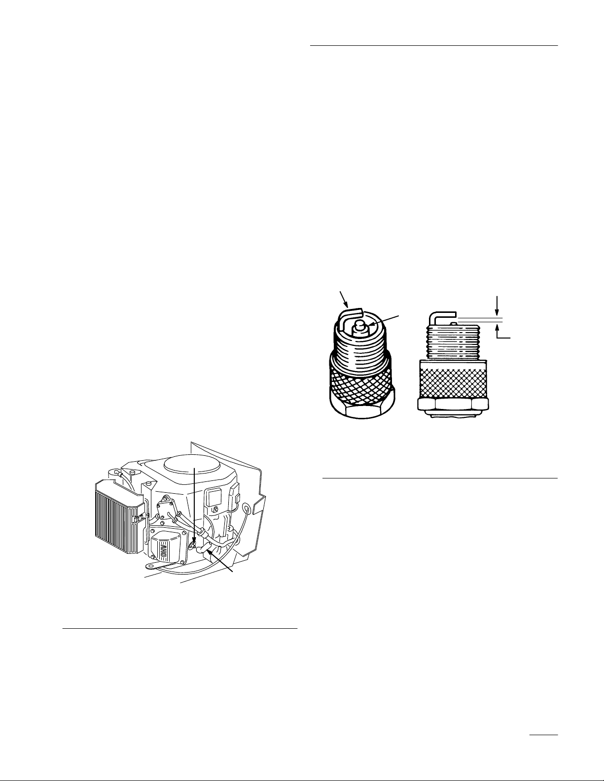
3. Pull the wire(s) off the spark plug(s) (Fig. 23).
Now clean around the spark plug(s) to prevent
dirt from falling into the engine and potentially
causing damage.
Checking the Spark Plug
1. Look at the center of the spark plug(s) (Fig. 24).
If you see light brown or gray on the insulator,
the engine is operating properly. A black coating
on the insulator usually means the air cleaner is
dirty.
IMPORTANT: Never clean the spark plug(s).
Always r
a black coating, worn electrodes, an oily film,
or cracks.
2. Check the gap between the center and side
electrodes (Fig. 24). Bend the side electrode
(Fig. 24) if the gap is not correct.
2
eplace the spark plug(s) when it has:
3
1
0.040”
mm)
(1.02
4. Remove the spark plug(s) and metal washer.
2
1
Figure 23
1. Spark
plug wire
2.
Spark plug
1215
24
3.
Air gap (not to scale)
1. Center
2.
Side electrode
Figure
electrode insulator
Installing the Spark Plug(s)
1. Install the spark plug(s) and metal washer. Make
sure the air gap is set correctly.
2. Tighten the spark plug(s) to 20 ft-lb (27 Nm).
3. Push the wire(s) onto the spark plug(s) (Fig. 23).
4. Close the hood.
27
Page 30
Maintenance
Greasing
and Lubrication
Service Interval/Specification
Grease the machine after every 50 operating hours or
yearly, whichever occurs first. Grease more frequently
when operating conditions are extremely dusty or
sandy.
Grease Type: General-purpose grease.
How to Grease
1. Disengage the power take off (PTO), set the
parking brake, and turn the ignition key to
“OFF” to stop the engine. Remove the key.
2. Clean the grease fittings with a rag. Make sure to
scrape any paint off the front of the fitting(s).
3. Connect a grease gun to the fitting. Pump grease
into the fittings until grease begins to ooze out of
the bearings.
4. Wipe up any excess grease.
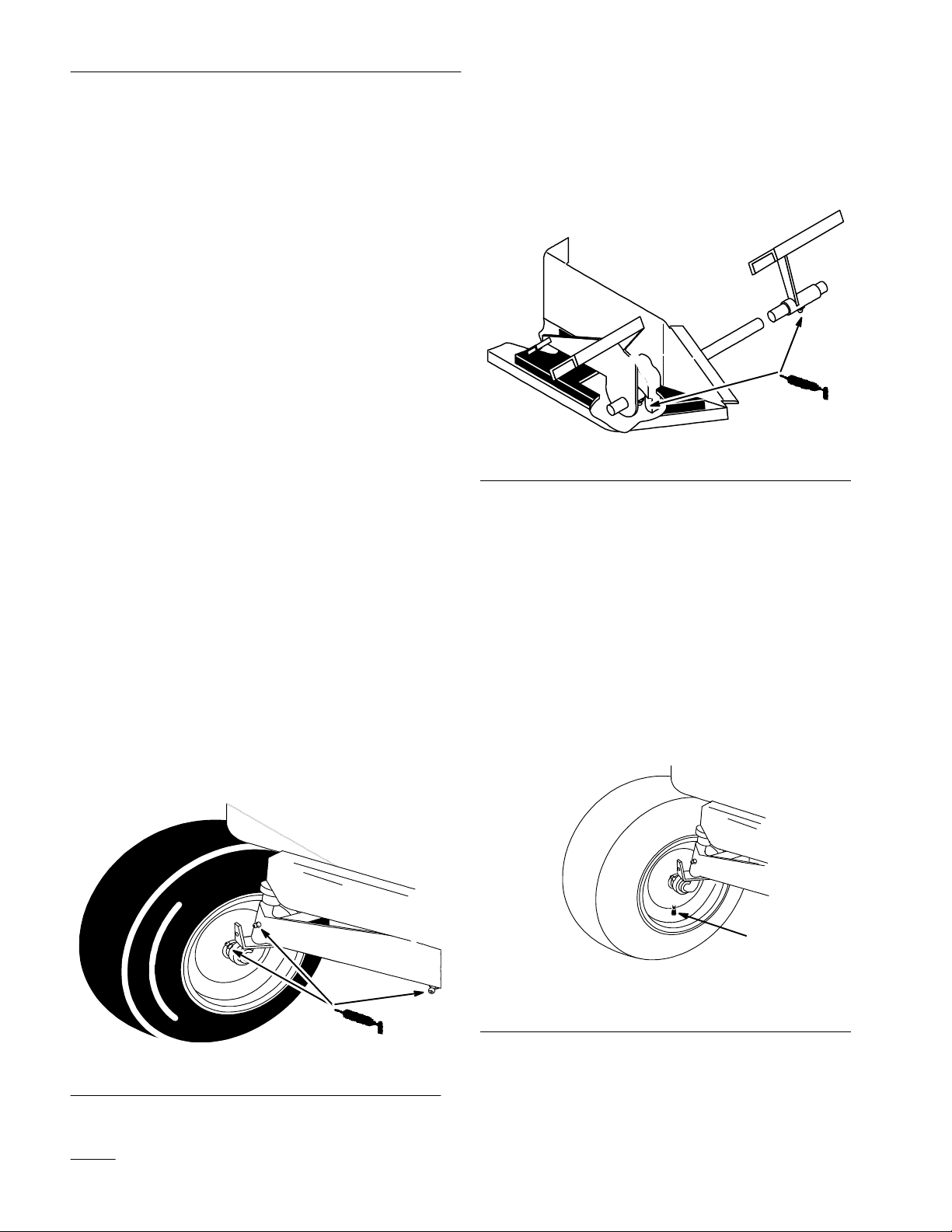
Where to Add Grease
1. Lubricate the front wheels and spindles until
grease begins to ooze out of the bearings
(Fig. 25).
3. Lubricate the traction control pedal on
hydrostatic models (or brake and clutch pedals
on gear drive models) where they pivot on
mounting shaft (Fig. 26).
1264
Figure 26
Tire
Pressure
Service Interval/Specification
Maintain the air pressure in the front and rear tires as
specified. Check the pressure at the valve stem after
every 25 operating hours or monthly, whichever
occurs first (Fig. 27). Check the tires when they are
cold to get the most accurate pressure reading.
Pressure: 20 psi (138 kPa) front and rear
2. Lubricate the front axle pivot (Fig. 25).
Figure 25
28
1211
Figure 27
1. Valve
stem
1
2323
Page 31
Maintenance
Brake
Always set the parking brake when you stop the
machine or leave it unattended. If the parking brake
does not hold securely, an adjustment is required.
Checking the Brake
1. Park the machine on a level surface, disengage
the power take off (PTO), set the parking brake,
and turn the ignition key to “OFF” to stop the
engine. Remove the ignition key.
2. Rear wheels must lock and skid when you try to
push the tractor forward. Adjustment is required
if the wheels turn and do not lock; refer to
Adjusting the Brake, page 29.
3. Move the drive control rod to the “PUSH”
position; refer to Pushing the Machine by Hand,
page 21. Wheels should rotate freely.
Adjusting the Brake
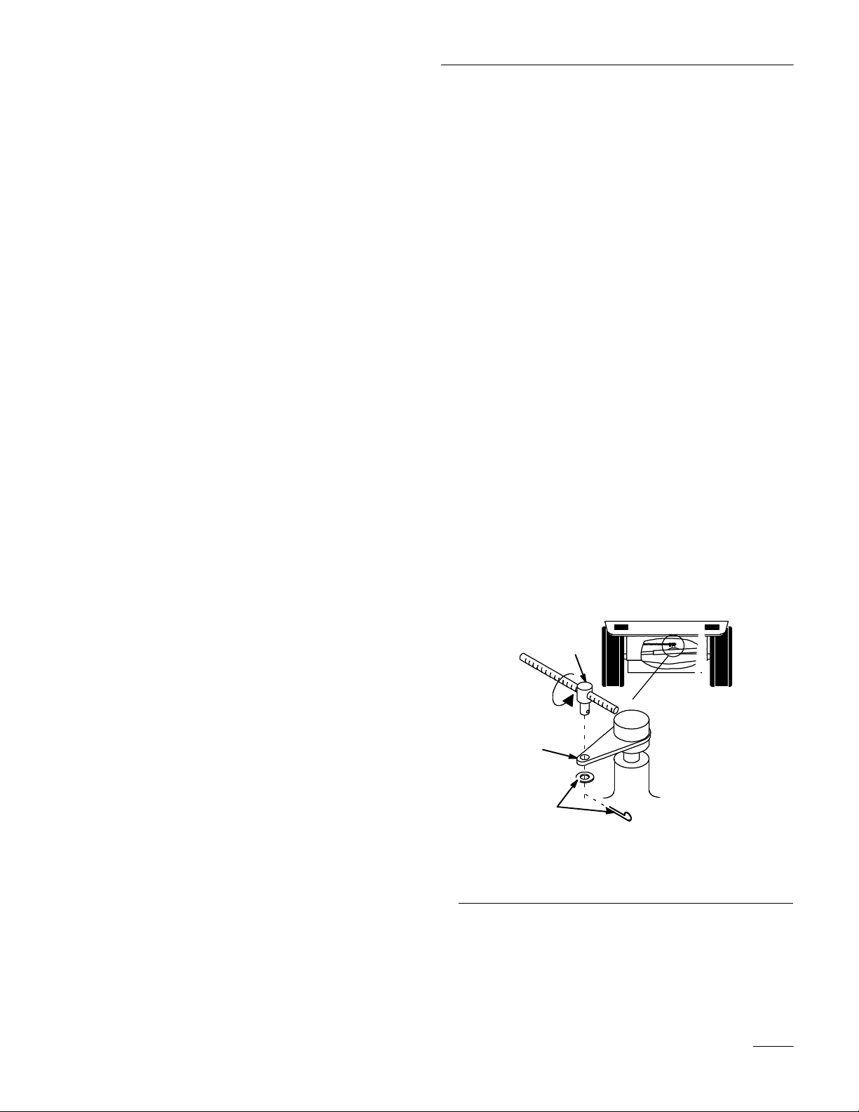
The brake lever is on top of the transaxle (Fig. 28). If
the parking brake does not hold securely, an
adjustment is required.
1. Check the brake before you adjust it; refer to
Checking the Brake, page 29.
2. Release the parking brake; refer to Releasing the
Parking Brake, page 13.
3. To adjust the brake remove the cotter pin and
washer from the brake lever (Fig. 28).
4. Rotate the trunnion so it smoothly slides into
brake lever (Fig. 28).
5. Secure trunnion to brake lever with washer and
cotter pin (Fig. 28).
6. Check the brake operation again; refer to
Checking the Brake, page 29.
4. If both conditions are met no adjustment is
required.
IMPORTANT: Drive control rod moves to the
“OPERATE” position when the brake is
applied.
IMPORTANT: With the parking brake
released, the rear wheels must rotate freely
when you push the mower. If brake action
and free wheel rotation cannot be achieved
contact your service dealer immediately.
2
3
1
Figure 28
1. Cotter
2. Trunnion
pin and washer
Brake lever
3.
1245
29
Page 32
Maintenance
Fuel Tank
Draining The Fuel Tank
POTENTIAL
• In certain conditions gasoline is extremely
flammable and highly explosive.
WHAT CAN HAPPEN
• A fire or explosion from gasoline can burn
you, others, and cause property damage.
HOW TO AV
• Drain gasoline from the fuel tank when the
engine is cold. Do this outdoors in an open
area. Wipe up any gasoline that spills.
• Never drain gasoline near an open flame or
where gasoline fumes may be ignited by a
spark.
• Never smoke a cigarette, cigar or pipe.
HAZARD
OID THE HAZARD
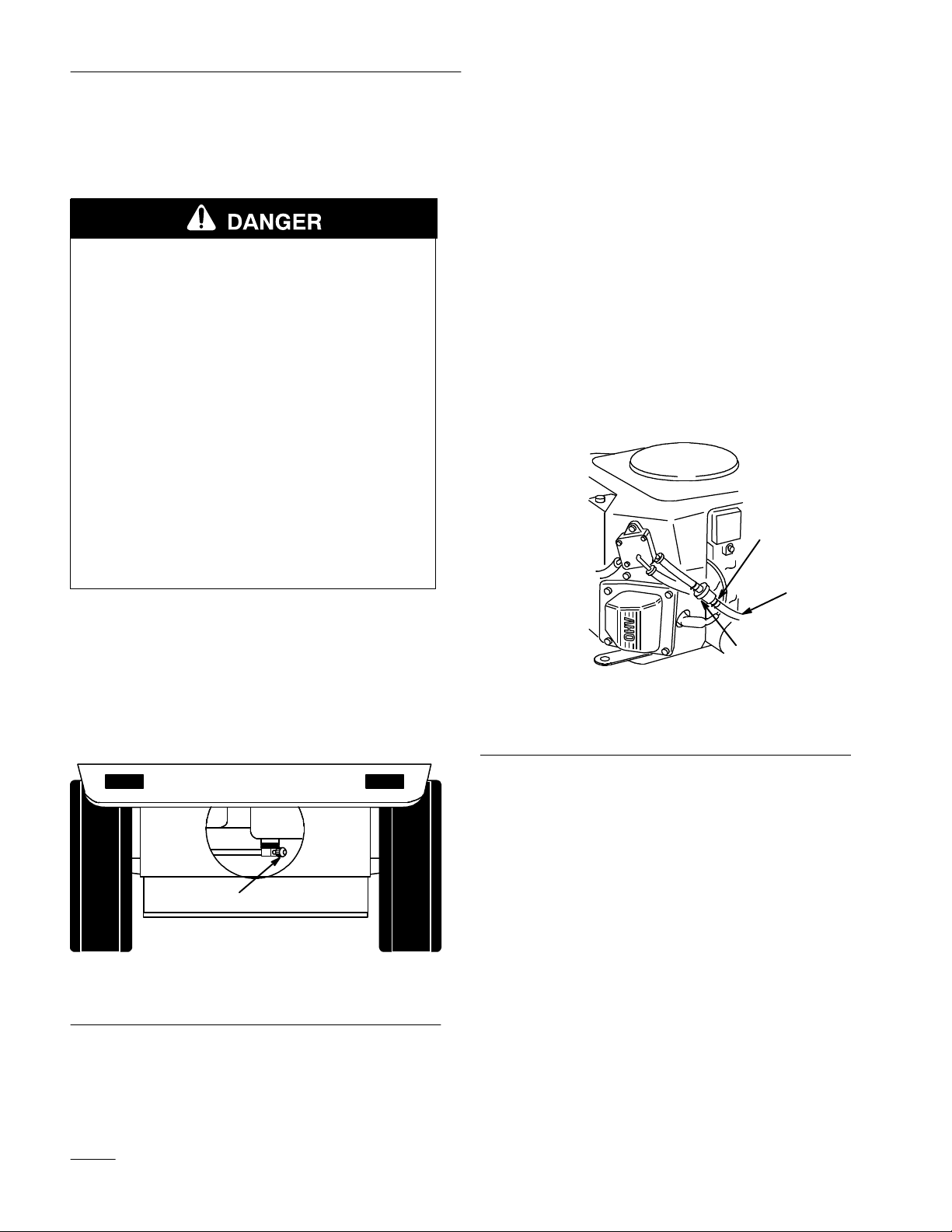
4. Squeeze the ends of the hose clamp together and
slide it up the fuel line toward the fuel tank
(Fig. 30).
5. Pull the fuel line off the filter (Fig. 30). Open
fuel shut-off valve and allow gasoline to drain
into a gas can or drain pan.
Note: Now is the best time to install a new
fuel filter because the fuel tank is
empty.
6. Install the fuel line onto the filter. Slide the hose
clamp close to the filter to secure the fuel line
and filter. Refer to Replacing the Fuel Filter;
page 31.
1
1. Park the machine on a level surface, to assure
fuel tank drains completely. Then disengage the
power take off (PTO), set the parking brake, and
turn the ignition key to “OFF” to stop the
engine. Remove the key.
2. Close fuel shut-off valve at fuel tank (Fig. 29).
1
1263
Figure 29
1. Fuel
shut-of
f valve
1. Hose
2.
Fuel line
clamp
Figure 30
3. Filter
2
3
1217
3. Open the hood.
30
Page 33
Maintenance
Fuel
Filter
Service Interval/Specification
Replace the fuel filter after every 100 operating hours
or yearly, whichever occurs first.
Replacing the Fuel Filter
Never install a dirty filter if it is removed from the
fuel line.
1. Disengage the power take off (PTO), set the
parking brake, and turn the ignition key to
“OFF” to stop the engine. Remove the key.
2. Close fuel shut–off valve at fuel tank (Fig. 29).
3. Open the hood.
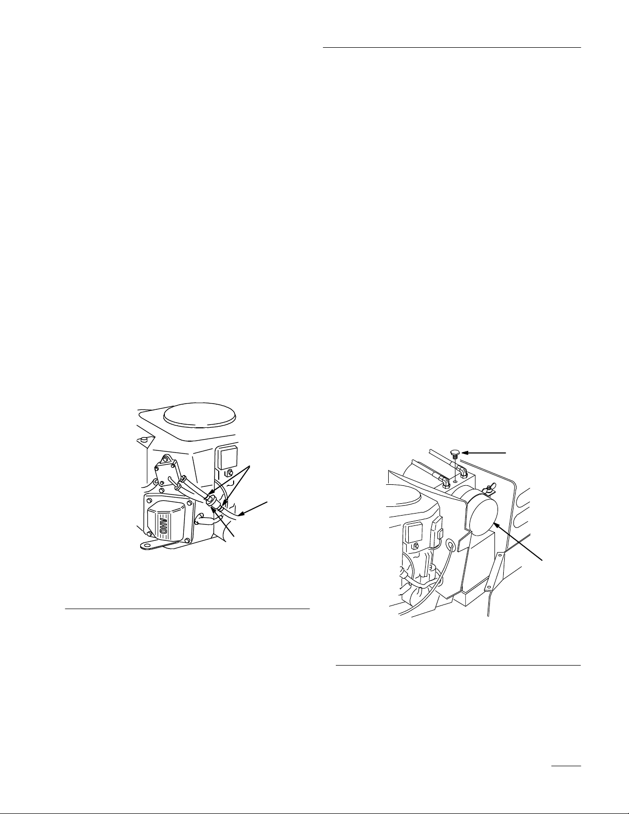
4. Squeeze the ends of the hose clamps together
and slide them away from the filter (Fig. 31).
5. Remove the filter from the fuel lines.
Power
Lift
Service Interval/Specification
Check fluid level in power lift after every 25
operating hours or yearly, whichever occurs first. Fill
with Dexron Type II or Type III automatic
transmission fluid.
Checking Fluid Level
1. Raise attachment lift to the full “UP” position.
Refer to: Raising Attachments page .
2. Disengage the power take off (PTO), set the
parking brake, and turn the ignition key to
“OFF” to stop the engine. Remove the key.
3. Open the hood.
4. Remove the plug on top of the power lift pump
(Fig. 32). Fluid should be level with the bottom
of the hole.
5. If fluid is below bottom of the hole fill with
Dexron Type II or Type III automatic
transmission fluid.
1
2
3
Figure 31
1. Hose
2.
clamp
Fuel line
3. Filter
6. Install a new filter and move the hose clamps
close to the filter.
7. Open fuel shut-off valve at fuel tank (Fig. 29).
8. Close the hood.
1217
1. Power
lift pump
2
1
2350
Figure 32
2. Plug
31
Page 34
Maintenance
Front
Wheel T
oe-In
Service Interval/Specification
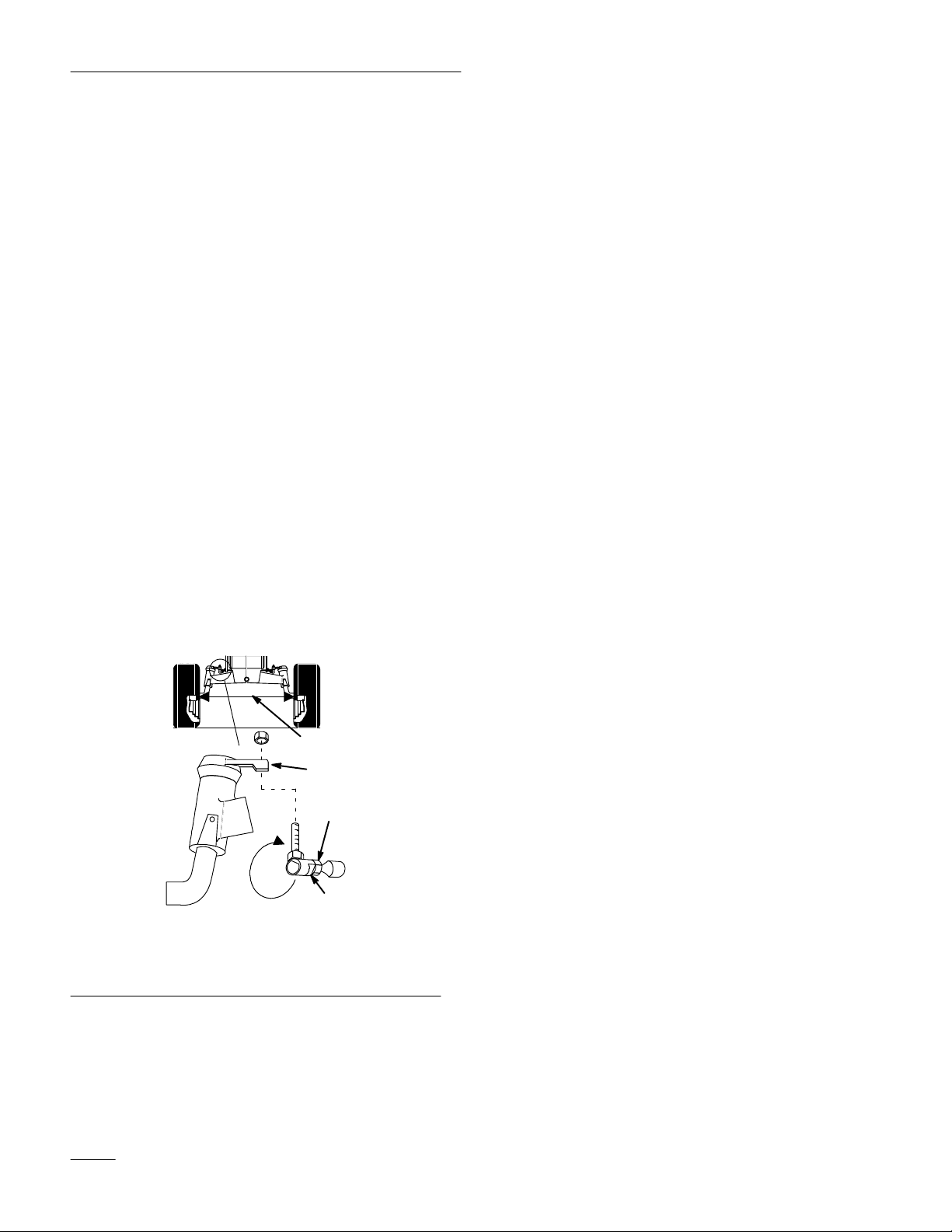
Maintain toe-in of the front wheels as specified. If
uneven tire wear, lawn scuffing or hard steering
develop adjustment may be required. Check the toe-in
after every 100 operating hours or yearly, whichever
occurs first (Fig. 33).
Specification: 1/8–1/4 inch toe-in on front wheels.
Measuring Toe-in
1. Disengage the power take off (PTO), set the
parking brake, and turn the ignition key to
“OFF” to stop the engine. Remove the key.
2. Push front tires out, at front, to remove normal
looseness in the linkage.
3. Measure, between the rims, at spindle level, in
the front and rear of the wheels (Fig. 33).
4. The front measurement should be less than the
rear, as specified.
Adjusting Toe-In
1. Check the toe-in before you adjust it; refer to
Measuring Toe-In, Page 32.
2. Remove ball joint from one steering lever
(Fig. 33).
3. Loosen jam nut securing ball joint to steering
rod. Rotate ball joint one turn, clockwise to
increase or counter clockwise to decrease toe-in.
4. Hold flats on ball joint to align with flats on tie
rod and tighten jam nut.
5. Install ball joint to steering lever and check the
toe-in; refer to Measuring Toe-In, Page 32.
IMPORTANT: If more than one turn is
required to meet specifications, alternate
between left and right steering rods to
maintain steering wheel alignment.
Transaxle
Fluid
Service Interval/Specification
1. Measure
2.
Ball joint flats
here
Figure 33
3.
4.
1
4
3
2
Jam nut
Steering lever
1261
Check fluid level after every 100 hours or yearly
whichever comes first. Always keep the fluid level at
the full level when the transaxle is cold. The transaxle
is a sealed system and no changing of the fluid is
required.
Fluid Type: SAE 10W–30 Detergent oil (API service
SF or SG)
Checking Fluid Level
1. Park the machine on a level surface, disengage
the power take off (PTO), set the parking brake,
and turn the ignition key to “OFF” to stop the
engine. Remove the key.
2. Open the hood.
3. Clean around the fluid reservoir (Fig. 34) so
level is clearly visible and so dirt cannot fall into
the reservoir if fluid is added.
32
Page 35
4. When transaxle is cold add oil to “Full Cold”
line on reservoir (Fig. 34).
Maintenance
IMPORTANT: Do not fill above the full cold
line as fluid may overflow.
1
2
1243
Figure 34
1. Fluid
reservoir
2.
Full cold level
Fuse
Service Interval/Specification
The electrical system is protected by fuses. It requires
no maintenance, however, if a fuse blows check
component/circuit for malfunction or short. To
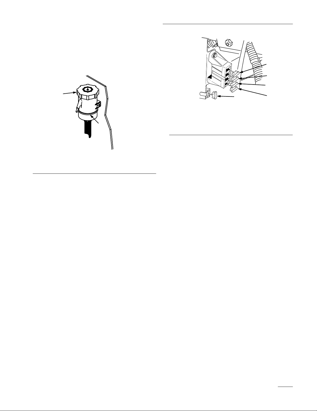
replace fuses pull up on the fuse (Fig. 35) to remove
or replace it.
Fuse: F1–30 amp, blade-type, Main/Starter
F2–25 amp, blade-type, Regulator
F3–10 amp, blade-type, Dash
F4–10 amp, blade-type, Headlights
F5–25 amp, blade-type, Lift
4
3
2
2337
1
1. Dash
2.
and Cruise control
-10
Amp
Head lights-10 amp
5
Figure 35
3.
4.
5.
Regulator-25 amp
Main-30 amp
Lift 25 amp
Headlights
Specification: Bulb # 1156 Automotive Type
Removing the Bulb
1. Disengage the power take off (PTO), set the
parking brake, and turn the ignition key to
“OFF” to stop the engine. Remove the key.
2. Open the hood. Pull wire connectors off both
bulb holder terminals.
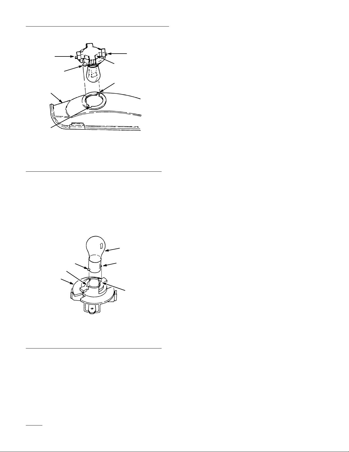
3. Rotate the bulb holder 1/4 turn counterclockwise
and remove it from the reflector (Fig. 36).
4. Push and rotate the bulb counterclockwise until
it stops (approx. 1/4 turn) and remove bulb from
the bulb holder (Fig. 37).
33
Page 36
Maintenance
5
2
2. The bulb holder has two tabs (Fig. 36). Align the
5
1
3
4
tabs with the slots in the reflector, insert the bulb
holder into the reflector and rotate it 1/4 turn
clockwise until it stops.
3. Push the wire connectors onto the terminals on
the bulb holder.
Battery
4
Figure 36
1. Bulb
holder
2. Reflector
3. Tabs
4. Slots
5. Terminals
Installing the Bulb
1. The bulb has metal pins on the side of its base.
Align the pins with the slots in the bulb holder
and insert the base into the holder (Fig. 37).
Push and rotate the bulb clockwise until it stops.
1
2
4
3
2
4
Service Interval/Specification
Check the electrolyte level in the battery before each
use. Always keep the battery clean and fully charged.
Use a paper towel to clean the battery case. If the
battery terminals are corroded, clean them with a
solution of four parts water and one part baking soda.
Apply a light coating of grease to the battery
terminals to prevent corrosion.
Voltage: 12 v, 280 Cold Cranking Amps
Removing the Battery
1. Disengage the power take off (PTO), set the
parking brake, and turn the ignition key to
“OFF” to stop the engine. Remove the key.
2. Open the hood to see the battery.
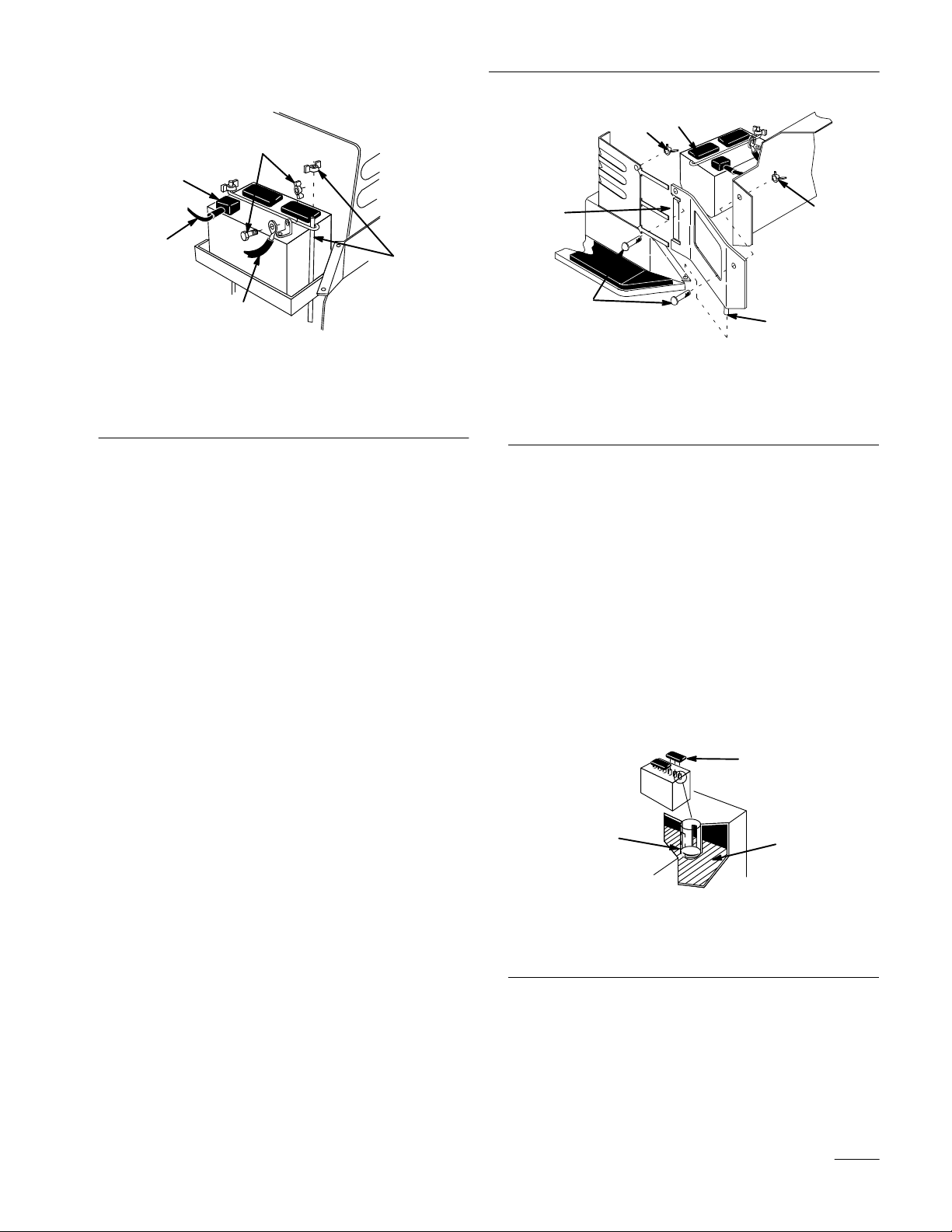
3. Remove side panels for clearance when
removing battery (Fig. 39). Remove the wing
nuts and screws and lift up to clear pin and slide
panel tabs out from steering tower.
1. Bulb
2. Metal
34
pins
Figure 37
3.
4. Slots
Bulb holder
4. Disconnect the negative (black) ground cable
from the battery post (Fig. 38).
5. Lift the rubber cover up on the positive (red)
cable. Disconnect the positive (red) cable from
the battery post (Fig. 38).
6. Remove the battery hold down rods (Fig. 38).
Page 37
Maintenance
1
4
4
2
3
5
1
1219
Figure 38
1. Negative
2.
Rubber cover
3.
Positive cable (red)
cable (black)
4.
Bolt and wing nut
5.
Hold down rod and wing
nut
Installing the Battery
7. Install the battery into the chassis (Fig. 39).
8. Secure battery in chassis with hold down rods.
9. Using the bolt and wing nut, connect the positive
(red) cable to the positive (+) battery post
(Fig. 38). Slide the rubber cover over the battery
post.
2
4
3
5
1260
Figure 39
1. Battery
2. Side
3. Screw
panel tabs
4.
Wing nut
5. Pin
Checking Electrolyte Level
1. With the engine off, open the hood to see the
battery.
2. Open covers to see into the cells. The electrolyte
must be up to the lower part of the tube
(Fig. 40). Do not allow the electrolyte to get
below the plates. (Fig. 40).
10. Using the bolt and wing nut, connect the
negative (black) cable to the negative (–) battery
post (Fig. 38).
11. Install side panels by sliding tabs into steering
tower and inserting pin into flange of footrest.
Secure with screws and wing nuts (Fig. 39).
3. If the electrolyte is low, add the required amount
of distilled water; refer to Adding Water to the
Battery, page 35.
1
2
3
1262
Figure 40
1. Filler
2.
caps
Lower part of tube
3. Plates
Adding Water to the Battery
The best time to add distilled water to the battery is
just before you operate the machine. This lets the
water mix thoroughly with the electrolyte solution.
35
Page 38

Maintenance
1. Clean the top of the battery with a paper towel.
2. Lift off the filler caps (Fig. 40).
3. Slowly pour distilled water into each battery cell
until the level is up to the lower part of the tube
(Fig. 40).
IMPORTANT: Do not overfill the battery
because electr
sever
e corr
4. Press the filler caps onto the battery.
olyte (sulfuric acid) can cause
osion and damage to the chassis.
Charging the Battery
IMPORTANT: Always keep the battery fully
charged (1.260 specific gravity). This is
especially important to prevent battery
damage when the temperature is below 32°F
(0°C).
1. Remove the battery from the chassis; refer to
Removing the Battery, page 34.
2. Check the electrolyte level; refer to Checking
Electrolyte Level, page 35, steps 2–3.
3. Remove the filler caps from the battery and
connect a 3 to 4 amp battery charger to the
battery posts. Charge the battery at a rate of 4
amperes or less for 4 hours (12 volts). Do not
overcharge the battery. Install the filler caps after
the battery is fully charged.
POTENTIAL HAZARD
• Charging the battery pr
WHAT CAN HAPPEN
oduces gasses.
• Battery gasses can explode.
HOW TO AV
OID THE HAZARD
• Keep cigarettes, sparks and flames away
from battery.
4. Install the battery in the chassis; refer to
Installing the Battery, page 35.
36
Page 39
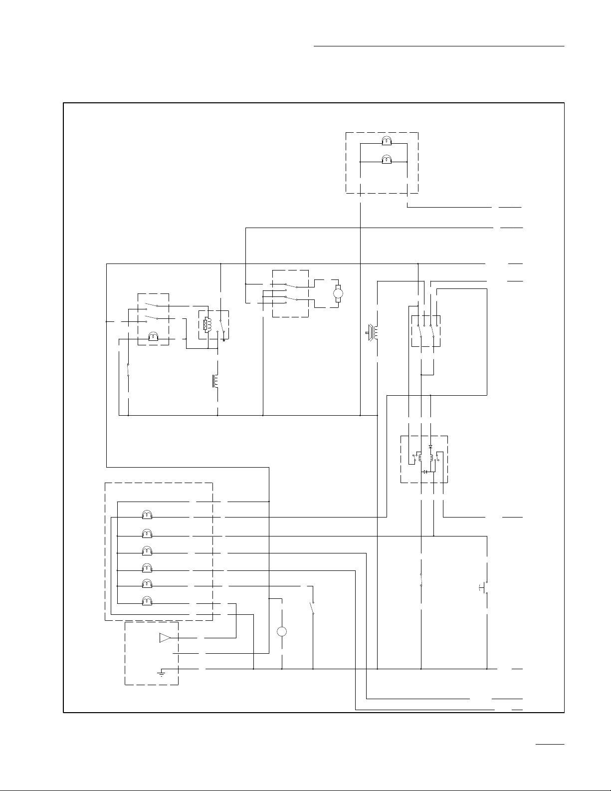
Maintenance
Wiring
Diagram
CRUISE SWITCH OPERATION
OFF NO CONNECTION
ON 3 AND 2 CONNECTED
MOMENTARY 3 AND 2 CONNECTED 5 AND 6 CONNECTED
PK
BK
SW7
CRUISE SWITCH
2
3
6
(MOMENTARY)
T
87
2
SW8
(CRUISE DISENGAGE SWITCH)
SWITCH OPENS WHEN
1
BRAKE IS DEPRESSED
Y
5
BU
BU
BK
PK
2
1
BU
BK
BU
BU
BK
K4
(CRUISE RELAY)
354
CRUISE MAGNET
SW10
1
2
3
4
5
6
(LIFT SWITCH)
OR
LIFT
PUMP
270 HYDRO
HEADLIGHT HARNESS
BK OR
BK OR
OR
BU
PK
GY
GY
PK W
W
BN
PTO
CLUTCH
BK
PK
BN
8
5
4
2
SW3
(PTO SWITCH)
PTO SWITCH IS
SHOWN IN OFF
POSITION
7
1
BUBU
BU
W
6
2
4
2328
WARNING LIGHT HARNESS
#194 LAMP
PTO
OIL
LOW
FUEL
#194 LAMP
#194 LAMP
#194 LAMP
#194 LAMP
OVER RIDE
TEMP
#194 LAMPBATTERY
B+
F
D
A
VOLTAGE
COMPARATOR
BATTERY LIGHT MODULE
A
PK PK
B
W W
C
T
Y Y
T
D
GNGN
H
G
E
OR OR
F
BK BK
OR
PK
BK
PK
BK
+
-
HOUR
METER
GYGYGY
C2C1
SW9
(LOW FUEL)
CLUTCH
NMIR
MODULE
SW5
(REVERSE SWITCH)
SWITCH OPENS WHEN
HYDRO PEDAL IS MOVED
TO REVERSE
1
3
5
BKGN T
GN
(KEY OVER RIDE)
SWITCH CLOSES
WHEN KEY IS
TURNED
BK
BK
T
SW6
BK
BK
GN
Y
37
Page 40
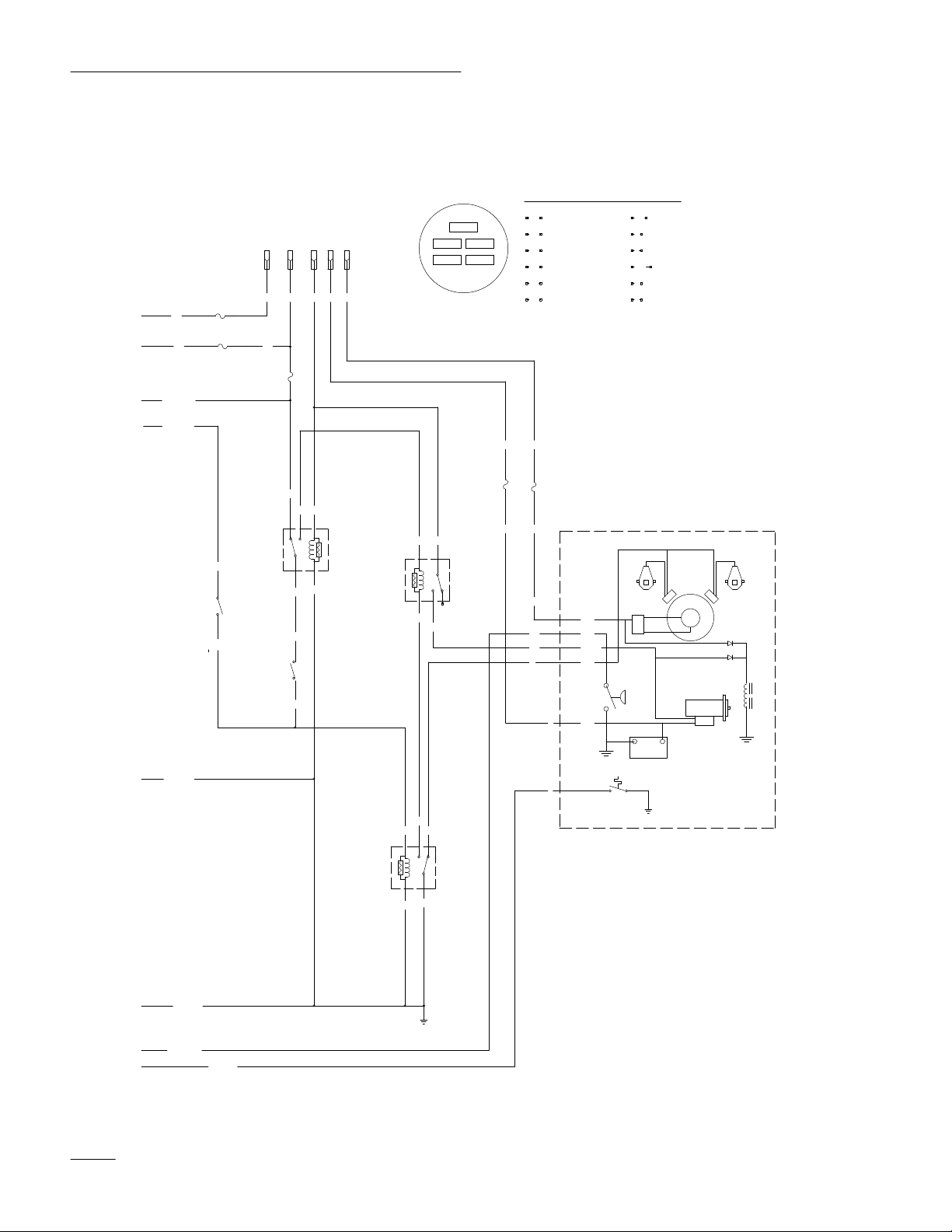
Maintenance
270 HYDRO
OR
PK
GY
SW4
(IGNITION SWITCH)
OFF-----------NO CONNECTION
RUN/LIGHTS----------B I R L
RUN---------------B I R
START--------------B I R S
I
B
1S5
PKOR
F4
10A
F5
25A
4L3
PKBU
F3
10A
PK
OR
BN
(INTERLOCK RELAY)
3
4
5
1
GY
SW2
1
(BRAKE SWITCH)
IS DEPRESSED
CLOSES WHEN BRAKE
3
BRAKE SWITCH
Y
SW1
(SEAT SWITCH)
SEAT SWITCH IS CLOSED
WHEN OPERATOR IS IN
THE SEAT
2
BK
T
T
Y
WIRE COLOR CODES
BK
F1
30A
BN
BU
GN
GY
OR
VIO
VIO
VIO
GN
BU
W
F2
25A
R
BLACK
BROWN
BLUE
GREEN
GREY
ORANGE
5
REG
3
OIL
2
START
1
MAG
4
B+
R
2
VIOBN R
S
R
B
L
I
IGNITION SWITCH TERMINAL
LOCATIONS VEIWED FROM BACK.
R
K2
OR BN
2
1
(START RELAY)
354
GN
BU
R
K3
PINK
PK
RED
R
TAN
T
VIOLET
VIO
WHITE
W
Y
YELLOW
SPARK PLUG SPARK PLUG
IGNITION
MODULES
AC
AC
SOLINOID
SHIFT
OIL
SWITCH
CLOSES WITH
PRESSURE
STARTER
+-
FUEL
SOLINIOD
38
BK
GN
BK
(TEMP. SWITCH)
SWITCH OPEN WITH
HIGH TEMPERATURE
2
BK
GN
WY
354
1
BK
K1
(KILL RELAY)
GND
Y
Y
Page 41

Maintenance
Cleaning and Storage
1. Disengage the power take off (PTO), set the
parking brake, and turn the ignition key to
“OFF” to stop the engine. Remove the key.
2. Remove grass clippings, dirt, and grime from the
external parts of the entire machine, especially
the engine. Clean dirt and chaff from the outside
of the engine’s cylinder head fins and blower
housing.
IMPORTANT: You can wash the machine
with mild detergent and water. DO NOT
PRESSURE W
Pressure washing may damage the electrical
system or wash away necessary gr
friction points. Avoid excessive use of water,
especially near the control panel, lights,
engine, and the battery.
3. Check the brake; refer to Brake, page 29.
4. Service the air cleaner; refer to Air Cleaner,
page 23.
5. Grease the chassis; refer to Greasing and
Lubrication, page 28.
6. Change the crankcase oil; refer to Engine Oil,
page 25.
7. Remove the spark plug(s) and check its
condition; refer to Spark Plug, page 27. With the
spark plug(s) removed from the engine, pour two
tablespoons of engine oil into the spark plug
hole. Now use the electric starter to crank the
engine and distribute the oil inside the cylinder.
Install the spark plug(s) and tighten it to 15 ft–lb
(20.4 Nm). Do not install the wire on the spark
plug(s).
8. Remove the battery from the chassis, check the
electrolyte level, and charge it fully; refer to
Battery, page 34. Do not connect the battery
cables to the battery posts during storage.
ASH THE MACHINE.
ease at
fully charged battery maintains its charge for
about 50 days at temperatures lower than
40°F (4°C). If the temperatures will be above
40°F (4°C), check the water level in the
battery and charge it every 30 days.
9. Check the tire pressure; refer to Tire Pressure,
page 28.
10. For long-term storage (more than 90 days) add
stabilizer/conditioner additive to fuel in the tank
(1 oz. per gallon) (8 ml per liter) and proceed as
follows:
A. Run the engine to distribute conditioned
fuel through the fuel system (5 minutes).
B. Stop the engine, allow it to cool and drain
the fuel tank; refer to Fuel Tank, page 30, or
operate engine until it stops.
C. Restart the engine and run until it stops.
Repeat, with the “CHOKE” on, until the
engine will not restart.
D. Dispose of fuel properly or use within 90
days for other applications. Recycle in
accordance with local codes.
Note: Do not store stabilizer/conditioned
gasoline over 90 days.
11. Check and tighten all bolts, nuts, and screws.
Repair or replace any part that is damaged or
defective.
12. Paint all scratched or bare metal surfaces. Paint
is available from your Authorized Service
Dealer.
13. Store the machine in a clean, dry garage or
storage area. Remove the ignition and “Key
Choice” keys and keep them in a memorable
place. Cover the machine to protect it and keep it
clean.
IMPORTANT: The battery must be fully
charged to prevent it from freezing and being
damaged at temperatures below 32°F (0°C). A
39
Page 42

Troubleshooting
g,,
gp
PROBLEM
Starter does not crank
Engine will not start, starts hard, or
fails to keep running.
POSSIBLE CAUSES
1.
Blade control (PT
ENGAGED.
2.
Parking brake is not on.
3.
Operator is not seated.
4.
Battery is dead.
5.
Electrical connections are
corroded or loose.
6.
Fuse is blown.
7.
Relay or switch is defective.
1.
Fuel tank is empty
2.
Choke is not ON.
3.
Air cleaner is dirty
4.
Spark plug wire is loose or
disconnected.
5.
Spark plug is pitted, fouled, or
gap is incorrect.
O) is
. 1.
. 3.
CORRECTIVE ACTION
1.
Move blade control (PT
DISENGAGED.
2.
Set parking brake.
3.
Sit on the seat.
4.
Charge the battery
5.
Check electrical connections
for good contact.
6.
Replace fuse.
7.
Contact Authorized Service
Dealer.
Fill fuel tank with gasoline.
2.
Move choke lever to ON.
Clean or replace air cleaner
element.
4.
Install wire on spark plug.
5.
Install new
spark plug.
, correctly gapped
O) to
.
Engine loses power
6.
Dirt in fuel filter
7.
Dirt, water
fuel system.
.
1.
Engine load is excessive.
2.
Air cleaner is dirty
3.
Oil level in crankcase is low
4.
Cooling fins and air passages
under engine blower housing
are plugged.
5.
Spark plug is pitted, fouled, or
gap is incorrect.
6. V
ent hole in fuel cap is
plugged.
7.
Dirt in fuel filter
8.
Dirt, water
fuel system.
. 6.
, or stale fuel is in
. 2.
. 7.
, or stale fuel is in
. 3.
Replace fuel filter
7.
Contact Authorized Service
Dealer.
1.
Reduce ground speed.
Clean air cleaner element.
Add oil to crankcase.
4.
Remove obstruction from
cooling fins and air passages.
5.
Install new
spark plug.
6.
Clean or replace the fuel cap.
Replace fuel filter
8.
Contact Authorized Service
Dealer.
.
, correctly gapped
.
40
Page 43

Troubleshooting
g
PROBLEM
Engine overheats.
Abnormal vibration.
Machine does not drive.
POSSIBLE CAUSES
1.
Engine load is excessive.
2.
Oil level in crankcase is low
3.
Cooling fins and air passages
under engine blower housing
are plugged.
1.
Engine mounting bolts are
loose.
2.
Loose engine pulley
pulley
, or blade pulley
3.
Engine pulley is damaged.
1.
Drive control is in “PUSH”
position.
2. T
raction belt is worn, loose or
broken.
3. T
raction belt is of
f pulley
, idler
.
. 3.
. 2.
CORRECTIVE ACTION
1.
Reduce ground speed.
Add oil to crankcase.
3.
Remove obstruction from
cooling fins and air passages.
1. T
ighten engine mounting
bolts.
2. T
ighten the appropriate
pulley.
3.
Contact Authorized Service
Dealer.
1.
Move drive control to
“OPERA
2.
Contact Authorized Service
Dealer.
Contact Authorized Service
Dealer.
TE” position.
41
Page 44

 Loading...