

Toro 72102, 72106, 72108, 72110, 72115 Service Manual
...
260-SERIES ELECTROHYDRAULIC LIFT SERVICE MANUAL
Table of Contents – Page 1 of 1
SAFETY INFORMATION
LIFT SYSTEM
COMPONENTS
PUMP ASSEMBLY COMPONENTS
108 SERIES POWER UNIT COMPONENTS
OPERATION
PUMP/VALVE DESCRIPTION
PUMP/VALVE COMPONENTS
ADAPTER BLOCK COMPONENTS (AS VIEWED FROM MOTOR END)
OIL FLOW AND CHECK VALVE OPERATION (AS VIEWED FROM MOTOR END)
PUMP IN NEUTRAL MODE
PUMP IN RAISE MODE
PUMP IN LOWER MODE
RELIEF VALVE TESTING (PUMP AS VIEWED FROM RESERVOIR END)
UP MODE
RELIEF VALVE REMOVAL/ADJUSTMENT PROCEDURE
DOWN MODE
RELIEF VALVE REMOVAL/ADJUSTMENT PROCEDURE
PUMP FLOW TESTING (PUMP AS VIEWED FROM RESERVOIR END)
CHECKING FLUID LEVEL
LIFT CYLINDER SERVICING
DESCRIPTION
REBUILD PROCEDURES
DISASSEMBLY
REASSEMBLY
CYLINDER HEAD
PISTON
LIFT SYSTEM ELECTRICAL COMPONENTS
WIRING DIAGRAMS
LIFT ELECTRICAL SYSTEM DE-ENERGIZED
LIFT ELECTRICAL SYSTEM ENERGIZED
LIFT SWITCH CURRENT FLOW
UP POSITION
DOWN POSITION
260-Series
Electrohydraulic Lift

About This Manual
This manual was written expressly for 260-Series Hydrostatic Tractors
equipped with an electrohydraulic lift system. The Toro Company has made
every effort to make the information in this manual complete and correct.
This manual was written for the service technician; basic mechanical/electrical
skills are assumed. The Contents page lists the systems and the related topics
covered in this manual.
We hope that you will find this manual a valuable addition to your service shop.
If you have any questions or comments regarding this manual, please contact
us at the following address:
The Toro Company
Consumer Service Training Department
8111 Lyndale Avenue South
Bloomington, MN 55420--1196
Portions of this manual are reprinted courtesy of New Holland North America.
The Toro Company reserves the right to change product specifications or this
manual without notice.
COPYRIGHT – ALL RIGHTS RESERVED
The Toro Company – 2000
Bloomington, MN 55420 – U.S.A
1

Contents
Safety Information 3.............................
Lift System 4....................................
Components 4....................................
Pump Assembly Components 6.....................
108 Series Power Unit Components 6...........
Operation 7......................................
Pump/Valve Description 7..........................
Pump/Valve Components 7.........................
Adapter Block Components
(as viewed from motor end) 7.....................
Oil Flow and Check Valve Operation
(as viewed from motor end) 7.....................
Pump in Neutral Mode 7.......................
Pump in Raise Mode 8........................
Pump in Lower Mode 8........................
Relief Valve Testing
(pump as viewed from reservoir end) 8.............
Up Mode 8...................................
Relief Valve Removal/Adjustment Procedure 8....
Down Mode 9................................
Relief Valve Removal/Adjustment Procedure 9....
Pump Flow Testing
(pump as viewed from reservoir end) 9.............
Checking Fluid Level 9........................
Lift Cylinder Servicing 10..........................
Description 10.....................................
Rebuild Procedures 10..............................
Disassembly 10...............................
Reassembly 11....................................
Cylinder Head 11..............................
Piston 11.....................................
Lift System Electrical Components 11.................
Wiring Diagrams 12................................
Lift Electrical System De-energized 12............
Lift Electrical System Energized 13...............
Lift Switch Current Flow 14..........................
Up Position 14.................................
Down Position 15..............................
2 Electrohydraulic Lift SystemContents

Safety Information
This symbol means WARNING or
PERSONAL SAFETY INSTRUCTION—
read the instruction because it has to do
with your safety. Failure to comply with
the instruction may result in personal
injury or even death.
This manual is intended as a service and repair manual
only. The safety instructions provided herein are for
troubleshooting, service, and repair of the
electrohydraulic lift system available with 260-Series
Think Safety First
Avoid unexpected starting of engine...
Always turn off the engine and disconnect the spark plug
wire(s) before cleaning, adjusting, or repair.
Avoid injury from high pressure oil...
Keep body and hands away from pin hole leaks or
nozzles that eject high pressure oil. Use cardboard or
paper to locate hydraulic leaks. Oil escaping under high
pressure can penetrate the skin and cause injury. Oil
accidentally injected into the skin must be surgically
removed within a few hours by a doctor familiar with this
form of injury or gangrene may result.
Avoid laceration and amputations...
hydrostatic tractors. The tractor and attachment
operator’s manuals contain safety information and
operating tips for safe operating practices. Operator’s
manuals are available through your local Toro distributor
or:
The Toro Company
Publications Department
8111 Lyndale Avenue South
Bloomington, MN 55420--1196
Avoid asphyxiation...
Never operate an engine in a confined area without
proper ventilation.
Avoid injury from batteries...
Battery acid is poisonous and can cause burns. Avoid
contact with skin, eyes, and clothing. Battery gases can
explode. Keep cigarettes, sparks, and flames away from
the battery.
Avoid injury due to inferior parts...
Use only original equipment parts to ensure that
important safety criteria are met.
Stay clear of all moving parts whenever the engine is
running. Treat all normally moving parts as if they were
moving whenever the engine is running or has the
potential to start.
Avoid burns...
Do not touch the engine, muffler, or other components
which may increase in temperature during operation,
while the unit is running or shortly after it has been
running.
Avoid fires and explosions...
Avoid spilling fuel and never smoke while working with
any type of fuel or lubricant. Wipe up any spilled fuel or
oil immediately. Never remove the fuel cap or add fuel
when the engine is running. Always use approved,
labeled containers for storing or transporting fuel and
lubricants.
Avoid injury to bystanders...
Always clear the area of bystanders before starting or
testing powered equipment.
Avoid injury due to projectiles...
Always clear the area of sticks, rocks, or any other debris
that could be picked up and thrown by the powered
equipment.
Avoid modifications...
Never alter or modify any part unless it is a factory
approved procedure.
Avoid unsafe operation...
Always test the safety interlock system after making
adjustments or repairs on the machine.
3Electrohydraulic Lift System Safety Information
Lift System
Components
The electrohydraulic lift system consists of the following
components:
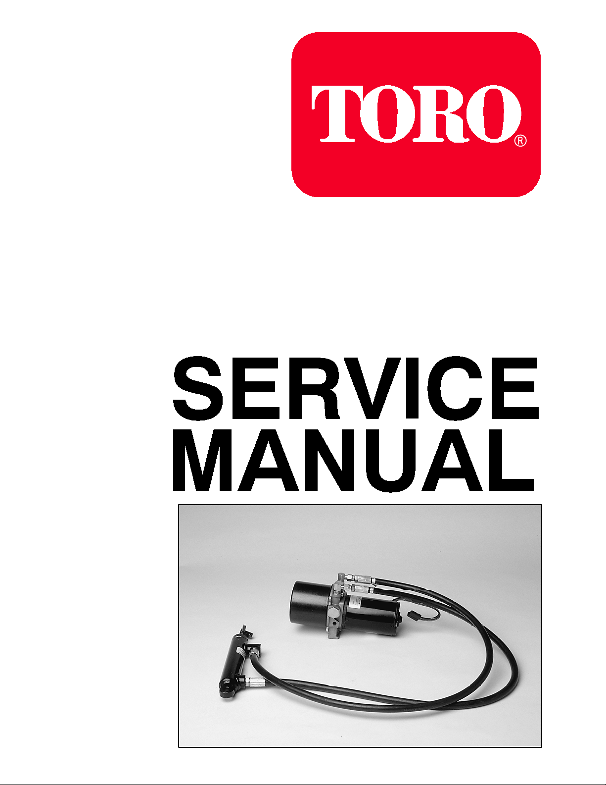
• Control Switch and Wire Harness
1
Figure 1
1. Control switch and wire harness
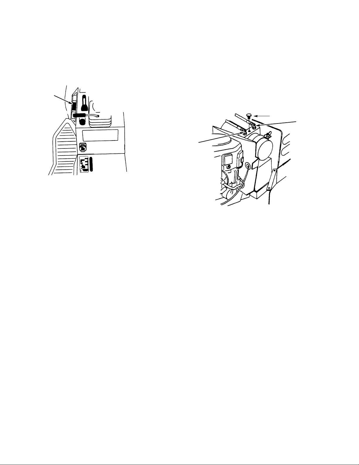
• Reservoir/Pump Assembly
Oildyne 108 series Power Unit model
108AE19--AL--1HT
Hydraulic Fluid -- Dexron II or Dexron III
Capacity -- 12.5 oz. (.4 liter), not including hoses or
cylinder.
1
2
Figure 2
1. Filler plug/vent
2. Hose to rear of lift cylinder
(Raise)
3. Hose to front of lift cylinder
(Lower)
3
4 Electrohydraulic Lift SystemLift System
 Loading...