

Page 1

FORM NO. 3321-863
LAWN & GARDEN TRACTOR
MODEL NO. 72070–9900600 & UP
MODEL NO. 72105–9900600 & UP
MODEL NO. 72115–9900600 & UP
Loose Parts
Note: Use the chart below to identify parts for assembly.
DESCRIPTION QTY. USE
Front Wheel
Flat Washer-large OD
Shim Washer
Dust Cover
Cotter Pin
Hub Cap (optional on some models)
Rear Wheel
Wheel Bolt
Hub Cap (optional on some models)
2
2
4
2
2
2
2
10
2
Install front wheels.
Install rear wheels.
SET UP
INSTRUCTIONS
Steering Wheel
Lock Washer 1/2”
Nut 1/2”
Logo Cover
Seat
Spacer-small ID
Spacer-large ID
Shoulder Bolt
Knob
Flat Washer
Bolt 1/4–20 x 3/4”
Wing Nut-plastic 1/4”
Key 1 Use in ignition and “Key Choke” switches.
Operator’s Manual 1 Read manual before operating tractor.
1
1
Install steering wheel.
1
1
1
2
2
Install the seat.
2
2
2
2
Attach battery cables.
2
The Toro Company – 1998
Printed in USA
All Rights Reserved
Page 2
Set Up Instructions
Install Front Wheels
Note: If wheels are already installed, refer to
Check Tire Pressure (below).
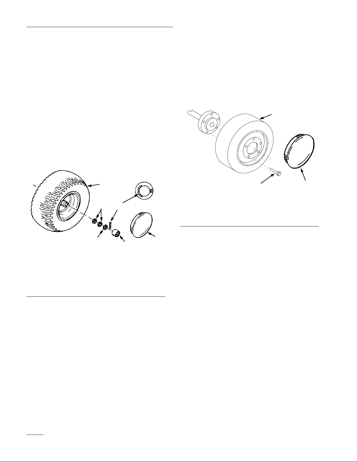
1. Slide wheel onto axle with valve stem in.
(Fig. 1).
2. Wheel end play should be 0-.015” (0-.4 mm).
Use shim washers (as required) and large OD flat
washer for spacing on the axle. Insert cotter pin
through the axle and bend the ends of the pin
open (Fig. 1).
3. Push the dust cover (Fig. 1) onto the end of the
axle so it snaps over washer.
1
2
4
Install Rear Wheels
1. Install wheel onto axle with valve stem to the
inside (Fig. 2).
2. Torque wheel bolts to 75-80 ft-lb (105-112 N.m).
3. Install hub caps, optional on some models.
1
1278 2
Figure 2
1. Wheel
2. Wheel bolts
3. Hub cap (optional)
3
1. Wheel
2. Shim washers (as
required)
3. Large OD flat washer
3
Figure 1
4. Cotter pin
5. Dust cover
6. Hub cap (optional)
5
4. Repeat steps 1–3 on opposite side.
5. Grease the wheel bearings.
6. Install hub caps, optional on some models.
6
Check Tire Pressure
Check front and rear tire pressure. See Operator’s
Manual for specification.
Pressure: 20 psi (138 kPa) front and rear.
2
Page 3
Set Up instructions
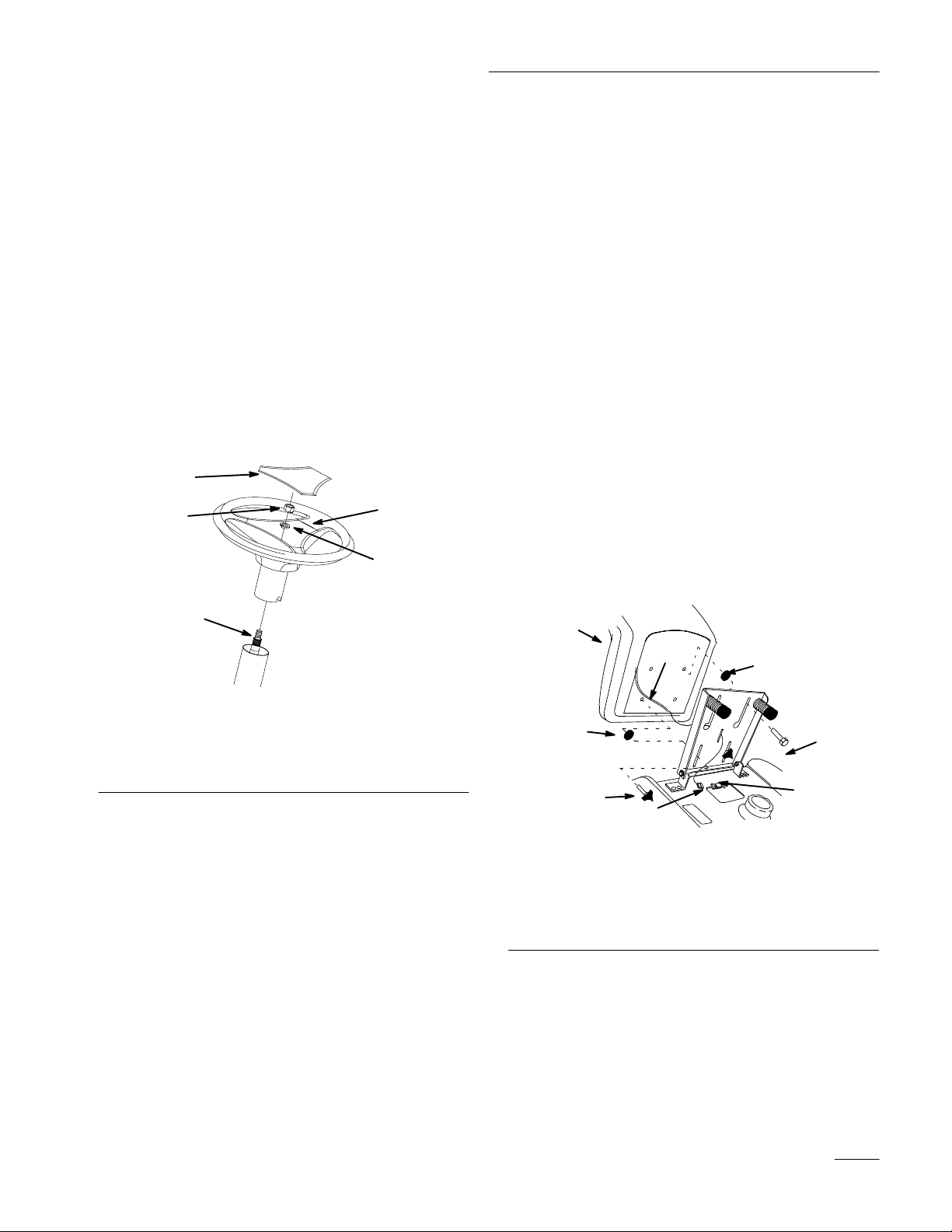
Install Steering Wheel
1. Position front wheels straight ahead.
2. Remove logo cover by releasing (3) latches from
back side with screwdriver.
3. Line up center spoke toward the seat and
position the steering wheel onto shaft spline
(Fig. 3).
4. Secure steering wheel with lockwasher and nut
(Fig. 3).
5. Torque steering wheel nut to 50 ft-lbs (37 N.m).
6. Snap logo cover into place (Fig. 3).
5
4
1
3
Install Seat
Note: If the seat is already installed, proceed
to Activate The Battery, page 4.
1. Install large ID spacer and shoulder bolts into
rear holes of seat (Fig. 4).
2. Position the seat onto the seat base by inserting
the two shoulder bolts through key hole
openings at the end of both slots (Fig. 4).
3. Locate small ID spacer between seat and seat
base, thread the knobs and flat washers into the
front holes in the seat (Fig. 4). Adjust the seat
and tighten the knobs.
4. Route seat switch wire and connector through
center opening in the seat base. Push the seat
switch connector fully into the wire harness
connector (Fig. 4).
5. Secure the seat switch wire cable to the fender
opening with wire clip (Fig. 4).
1. Center spoke
2. Shaft spline
3. Lock washer
2
2307
Figure 3
4. Nut
5. Logo cover
1. Seat
2. Spacer-small ID
3. Spacer-large ID
4. Bolt and flat washer
1
6
2
5
7
Figure 4
5. Knob and flat washer
6. Wire and connector
7. Wire harness connector
8. Wire clip
3
4
8
1271
3
Page 4

Set Up Instructions
Activate the Battery
Bulk electrolyte with 1.260 specific gravity must be
purchased from a local battery supply outlet.
1. Remove the battery from the tractor: refer to
Operator’s Manual, Removing the Battery.
IMPORTANT: Be careful not to damage the
long vent tube when removing the battery
box.
POTENTIAL HAZARD
• Battery electrolyte contains sulfuric acid
which is a deadly poison and it causes
severe burns.
WHAT CAN HAPPEN
• If you carelessly drink electrolyte you could
die or if it gets onto your skin you will be
burned.
1
3
Figure 5
1. Filler caps
2. Electrolyte
3. Lower part of the tube
3. Leave the covers off and connect a 3 to 4 amp
battery charger to the battery posts (Fig. 6).
Charge the battery at a rate of 4 amperes or less
for 4 hours (12 volts).
2
1262
HOW TO AVOID THE HAZARD
• Do not drink electrolyte and avoid contact
with skin, eyes or clothing. Wear safety
glasses to shield your eyes and rubber
gloves to protect your hands.
• Fill the battery where clean water is always
available for flushing the skin.
• Follow all instructions and comply with all
safety messages on the electrolyte container.
2. Remove filler caps from the battery. Slowly pour
electrolyte into each cell until the electrolyte
level is up to the lower part of the tube (Fig. 5).
1. Positive post
2. Negative post
4
2
3
1
1254
Figure 6
3. Charger red (+) wire
4. Charger black (–) wire
4
Page 5

Check Safety System
Set Up instructions
POTENTIAL HAZARD
• Charging battery produces gasses.
WHAT CAN HAPPEN
• Battery gasses can explode.
HOW TO AVOID THE HAZARD
• Keep cigarettes, sparks and flames away
from battery.
4. When the battery is fully charged, disconnect the
charger from the electrical outlet then from the
negative and positive battery posts (Fig. 6).
5. Slowly pour electrolyte into each cell until the
level is once again up to the “UPPER” line on
the battery case (Fig. 5) and install covers.
6. Install the battery in the tractor and connect
cables with (2) 1/4 x 3/4” bolts and (2) 1/4”
plastic wing nuts: refer to the Operator’s
Manual, Installing the Battery.
Refer to the Operator’s Manual, Checking Safety
System.
Electric Clutch Break-In
The electric clutch requires initial break-in to seat the
mating surfaces. Engage/disengage the clutch 10-20
cycles with the mower installed. Rotating the blades
provides load for break-in.
Adjust Electric Clutch
The electric clutch has three (3) adjustment nuts that
all must be adjusted the same (Fig. 7).
1. Insert a 0.010 inch (.25 mm) feeler gauge into
the slot (Fig. 7).
2. Turn the nut until light resistance is felt on the
gauge.
Crankcase Oil
Check the engine oil level, refer to the Operator’s
Manual, Engine Oi. If necessary, add only enough oil
to raise the level to the “FULL” mark on the dipstick.
Note: Slide the oil dipstick fully into the
filler tube, do not thread onto fill tube.
Lubricate the Tractor
Refer to the Operator’s Manual, Greasing and
Lubrication.
If equipped with Power Lift, check reservoir level, fill
with Dexron Type II.
3. Repeat for all three adjusting nuts.
1
3
2
Figure 7
1. Slot
2. 0.010” (25 mm) Feeler
gauge
3. Adjusting nut
Test Drive the Tractor
Make sure all electrical and mechanical systems are
operating properly.
1276
5
Page 6

Page 7

Page 8

 Loading...