

Toro 72052, 72072 Parts Catalogue

266–H and 266–HE
Yard and Garden Tractor
Model No. 72052 and 72072—210000001 and Up
Form No. 3324–687
Parts Catalog
Ordering Replacement Parts
To order replacement parts, please supply: the part
number, the quantity, and the description of each
part desired.
Understanding Reference Numbers
Each identified part in an illustration has a reference
number. The reference number for a part also appears in
the parts list, along with other information about the part.
This catalog uses two special reference number formats,
one to indicate parts in a service assembly and another
to indicate the quantity of a given part in an illustration.
Service Assembly Reference Numbers
Parts in service assemblies have reference numbers in
the form a:b.
the entire service assembly and the b represents a
sequential number unique to each part within the service
assembly.
The a represents the reference number of
The TORO Company — 2001
All Rights Reserved
For example, a wheel assembly might be identified by
reference number 6, the tire by 6:1, the valve by 6:2,
and the wheel by 6:3. When you order the assembly
identified by reference number 6, you receive all parts
identified by reference numbers 6:1, 6:2, and 6:3.
However, you may also order any part individually.
Reference numbers of this type appear in illustrations
and in part lists.
Reference Numbers Indicating Quantity
In an illustration, if a reference number indicates more
than one part, the reference number has the form nX y.
The n represents the quantity of the part, the X is the
multiplication symbol, and the y represents the reference
number.
For example, in an illustration, the reference number
2X 37 means that two of the parts identified by reference
number 37 are indicated.

3324–687
Contents
Description Page Description Page
Hood and Grill Assembly 4. . . . . . . . . . . . . . . . . . .
Hydro Drive Assembly 5. . . . . . . . . . . . . . . . . . . . .
Front Axle Assembly 6. . . . . . . . . . . . . . . . . . . . . . .
Battery Assembly 7. . . . . . . . . . . . . . . . . . . . . . . . .
Fuel Tank Assembly 8. . . . . . . . . . . . . . . . . . . . . . .
Lower Steering Assembly 9. . . . . . . . . . . . . . . . . .
Steering Wheel and Tilt Assembly 10. . . . . . . . . . .
Hoodstand and Firewall Assembly 11. . . . . . . . . . .
Lift Lever Arm and Height–Of–Cut Assembly 12. .
Hydraulic Brake Assembly 13. . . . . . . . . . . . . . . . . .
Hydraulics Controls Assembly 14. . . . . . . . . . . . . . .
Frame Assembly 15. . . . . . . . . . . . . . . . . . . . . . . . . .
Hydrostatic Transaxle Assembly 16. . . . . . . . . . . . .
Engine, Muffler and PTO Assembly 17. . . . . . . . . .
Fender and Footrests Assembly 18. . . . . . . . . . . . .
Seat Assembly 19. . . . . . . . . . . . . . . . . . . . . . . . . . . .
Dash Assembly 20. . . . . . . . . . . . . . . . . . . . . . . . . . .
Rear Wheels Assembly 21. . . . . . . . . . . . . . . . . . . .
Cruise Control Assembly 22. . . . . . . . . . . . . . . . . . .
Housing and Fan Assembly 23. . . . . . . . . . . . . . . . .
Differential Gear Assembly 24. . . . . . . . . . . . . . . . .
Brake Assembly 25. . . . . . . . . . . . . . . . . . . . . . . . . . .
Cylinder Block Assembly 26. . . . . . . . . . . . . . . . . . .
Schematic 27. . . . . . . . . . . . . . . . . . . . . . . . . . . . . . . .
Crankshaft Assembly
Kohler Models CV460S–26505 and
CV460S–26506 28. . . . . . . . . . . . . . . . . . . . . . . . .
Crankcase Assembly
Kohler Models CV460S–26505 and
CV460S–26506 29. . . . . . . . . . . . . . . . . . . . . . . . .
Oil Pan / Lubrication Assembly
Kohler Models CV460S–26505 and
CV460S–26506 30. . . . . . . . . . . . . . . . . . . . . . . . .
Cylinder Head / Valve / Breather Assembly
Kohler Models CV460S–26505 and
CV460S–26506 31. . . . . . . . . . . . . . . . . . . . . . . . .
Ignition / Electrical Assembly
Kohler Models CV460S–26505 and
CV460S–26506 32. . . . . . . . . . . . . . . . . . . . . . . . .
Blower Housing & Baffles Assembly
Kohler Models CV460S–26505 and
CV460S–26506 33. . . . . . . . . . . . . . . . . . . . . . . . .
Starting System Assembly
Kohler Models CV460S–26505 and
CV460S–26506 34. . . . . . . . . . . . . . . . . . . . . . . . .
Fuel System Assembly
Kohler Models CV460S–26505 and
CV460S–26506 35. . . . . . . . . . . . . . . . . . . . . . . . .
Engine Controls Assembly
Kohler Models CV460S–26505 and
CV460S–26506 36. . . . . . . . . . . . . . . . . . . . . . . . .
Air Intake / Filtration Assembly
Kohler Models CV460S–26505 and
CV460S–26506 37. . . . . . . . . . . . . . . . . . . . . . . . .
Exhaust Assembly
Kohler Models CV460S–26505 and
CV460S–26506 38. . . . . . . . . . . . . . . . . . . . . . . . .
Accessories
Description Model / Part No. Description Model / Part No.
38” Side Discharge Mower
(Model No. 72052 Only) Model No. 78216. . . . . .
42” Side Discharge Mower
(Model No. 72052 Only) Model No. 78231. . . . . .
48” Side Discharge Mower
(Model No. 72052 Only) Model No. 78261. . . . . .
52” Side Discharge Mower
(Model No. 72052 Only) Model No. 78281. . . . . .
38” Side Discharge Mower
(Model No. 72072 Only) Model No. 78218. . . . . .
42” Side Discharge Mower
(Model No. 72072 Only) Model No. 78232. . . . . .
48” Side Discharge
(Model No. 72072 Only) Model No. 78268. . . . . .
11 Cubic Foot Twin Bagger
(For 38” SD Mower) Model No. 79202. . . . . . . . . .
11 Cubic Foot Twin Bagger
(For 42” & 48” SD Mower) Model No. 79203. . . .
36” Tiller Model No. 79271. . . . . . . . . . . . . . . . . . . . .
2
48” Dozer Blade Model No. 79253. . . . . . . . . . . . . .
42” Snowthrower Model No. 79263. . . . . . . . . . . . . .
38” Recycler Kit Model No. 79170. . . . . . . . . . . . . . .
Indicator Lights
(Model No. 72072 Only) Part No. 98–6831. . . .
Baffle Kit – 42” SD Mower Model No. 85501. . . . . .
48” Blade Adapter Part No. 92–6828. . . . . . . . . . . .
42” Snowthrower Adapter Part No. 93–7625. . . . .
48” Recycler Kit Model No. 79195. . . . . . . . . . . . . . .
48” Blade Skid Shoe Part No. 92–6840. . . . . . . . . .
Cruise Control Kit Part No. 93–0510. . . . . . . . . . . .
Rear Wheel Weights Part No. 81115. . . . . . . . . . . . .
Front Wheel Weights Part No. 81214. . . . . . . . . . . .
Tire Chains Part No. 82522. . . . . . . . . . . . . . . . . . . . .
Cab Part No. 79911. . . . . . . . . . . . . . . . . . . . . . . . . . .
R.H. Cleat Tire Part No. 92–6789. . . . . . . . . . . . . . .
L.H. Cleat Tire Part No. 92–6790. . . . . . . . . . . . . . .
Non Metalic Hubcap – 8” Part No.94–3717. . . . . . .
Non Metalic Hubcap – 12” Part No.94–3718. . . . . .

Part Description Abbreviations
Part descriptions in this catalog may include the following abbreviations.
Abbreviation Meaning Abbreviation Meaning
AR as required. . . . . . . . . . . . . . . . .
ASM assembly. . . . . . . . . . . . . . . .
CARR carriage. . . . . . . . . . . . . .
DEG degrees. . . . . . . . . . . . . . . .
FH flat head. . . . . . . . . . . . . . . . .
GA gauge. . . . . . . . . . . . . . . . .
HF hex flange. . . . . . . . . . . . . . . . .
HH hex head. . . . . . . . . . . . . . . . .
HHF hex head flange. . . . . . . . . . . . . . . .
HLH hex lag head. . . . . . . . . . . . . . . .
HJ hex jam. . . . . . . . . . . . . . . . . .
HOC height-of-cut. . . . . . . . . . . . . . . .
HS hex socket. . . . . . . . . . . . . . . . .
HSBH hex socket button head. . . . . . . . . . . . . .
HSFH hex socket flat head. . . . . . . . . . . . . . .
HSH hex socket head. . . . . . . . . . . . . . . .
HWH hex washer head. . . . . . . . . . . . . . .
HWHTF hex washer head. . . . . . . . . . . . .
thread forming
HYD hydraulic. . . . . . . . . . . . . . . .
INC incorporated. . . . . . . . . . . . . . . . .
LH left hand. . . . . . . . . . . . . . . . .
NI nylon insert. . . . . . . . . . . . . . . . . .
PPH Phillips pan head. . . . . . . . . . . . . . . .
PTH Phillips truss head. . . . . . . . . . . . . . . .
PTO power take off. . . . . . . . . . . . . . . .
RH right hand. . . . . . . . . . . . . . . . .
SFH slotted fillister head. . . . . . . . . . . . . . . .
SHH slotted hex head. . . . . . . . . . . . . . . .
SQH square head. . . . . . . . . . . . . . . .
SHWH slotted hex washer head. . . . . . . . . . . . . .
SPH slotted pan head. . . . . . . . . . . . . . . .
SRH slotted round head. . . . . . . . . . . . . . . .
STD standard. . . . . . . . . . . . . . . .
TAP self tapping. . . . . . . . . . . . . . . .
TTH Torx truss head. . . . . . . . . . . . . . . .
WH wing head. . . . . . . . . . . . . . . . .
3324–687
3
3324–687
1
2
24
26
28
28:3
28:2
10
27
28:1
23
33
32
31
29
30
15
16
22
5
5
20
21
19
19
17
18
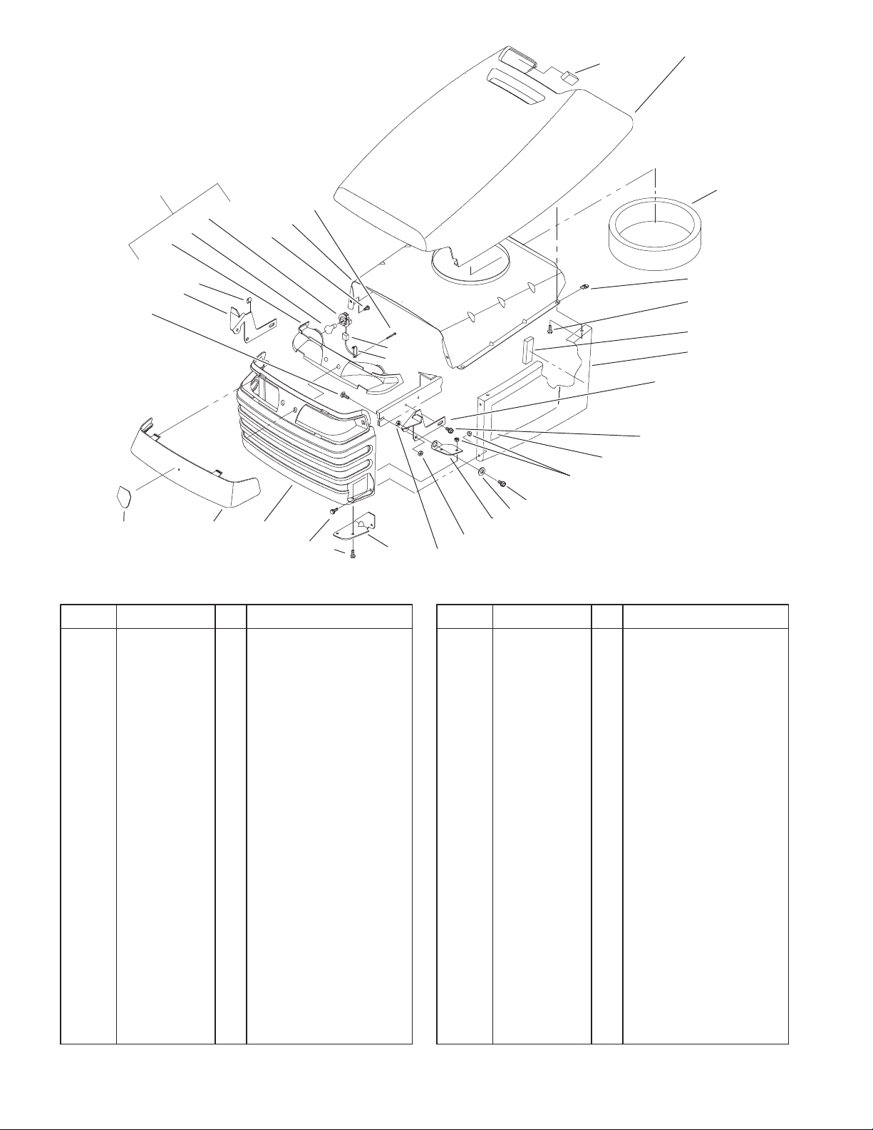
Hood and Grill Assembly
14
3
4
5
6
7
8
9
11
12
13
Sheet No.:2
DescriptionPart No. Qty.Ref. No. DescriptionPart No. Qty.Ref. No.
1 94–1980 2 Foam – Hood
2 92–6658 1 Hood – Top
3 92–7077 1 Seal–Air Inlet
4 92–7006 4 Nut
5 32105–15 12 Screw
6 92–7148 2 Foam – Sidepanel
7 92–6652 1 Side–LH Hood
*8 92–6650 1 Side–RH Hood
9 92–6918–03 1 Bracket–Hinge, LH
10 92–6917–03 1 Bracket–Hinge, RH
11 32144–14 2 Screw–HWH
12 95–0801 1 Decal–Hood, LH
*13 95–0800 1 Decal–Hood, RH
14 32128–10 8 Locknut–Flange
15 322–3 2 Screw–HH
16 105503 2 Bushing
17 92–6997–03 1 Hinge–Hood, LH
*18 92–6996–03 1 Hinge–Hood, RH
19 3296–29 4 Nut–Lock
20 92–7049–03 1 Bracket–Hood Hinge,
RH
*21 92–7048–03 1 Bracket–Hood Hinge,
LH
22 100–1344 1 Grill
23 92–6656 1 Lens – Headlight
24 92–6987 1 Emblem–Horsehead
26 3230–1 2 Screw–CARR
27 519337 1 Clip–Cable
28 88–3970 1 Reflector & Lamp ASM
28:1 111686 2 Socket–Light
28:2 7228 2 Bulb –No. 1156
28:3 93–8741 1 Reflector
29 88–4320 1 Wire Harness–Lights
30 614249 1 Tie–Strap
31 46–8093 2 Screw–Plastite
32 92–6914–03 1 Baffle–Hood, Upper
33 32144–32 2 Screw
* Not illustrated
4

2
1
3
4
5
4
11
5
12
5
9
10
9
5
6
5
8
5
9
1
9
7
3324–687
Sheet No.:3
Hydro Drive Assembly
DescriptionPart No. Qty.Ref. No. DescriptionPart No. Qty.Ref. No.
1 2534 2 Clip – Spring
2 3231–25 1 Screw–CARR
3 111419 1 Bearing–Washer
4 323–10 2 Screw–HH
5 3256–24 6 Washer–Flat
6 92–6900 1 Arm – Idler
7 79–7530 1 Spring – Clutch
8 92–7101 1 Pulley – Flat Idler
9 3296–59 4 Nut–Lock NI
10 111418 1 Bushing
11 93–3658 1 Spacer
12 92–7102 1 Pulley – Idler
5
3324–687
2
3
1
4
5:99
5:1
9
9
8
7
6
10
10:3
10:1
10:2
12
14
5:2:1
5:2:3
5:2:2
5:2
15
20
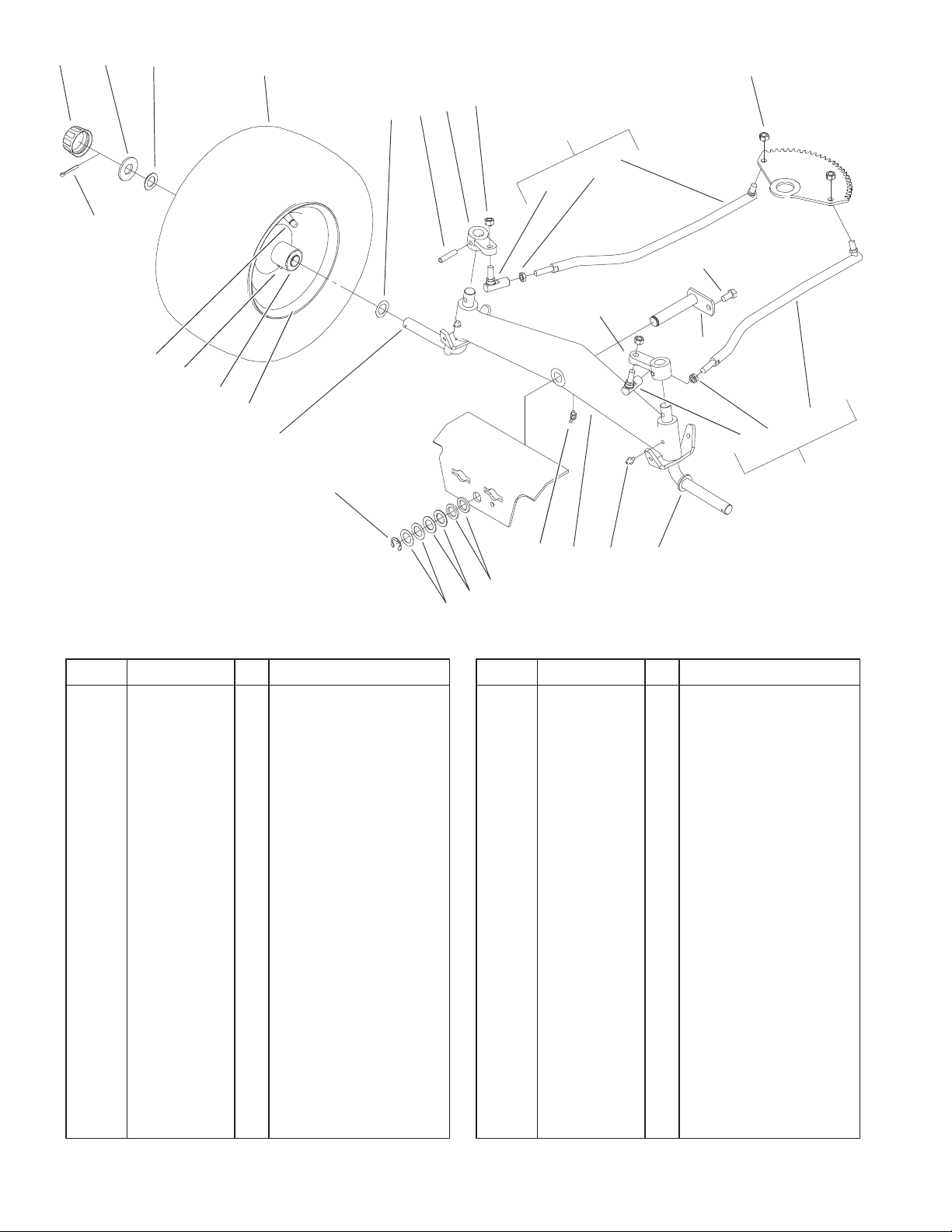
Front Axle Assembly
DescriptionPart No. Qty.Ref. No. DescriptionPart No. Qty.Ref. No.
1 3272–17 2 Pin–Cotter
2 61–9780 2 Cap–Hub
3 28–2480 2 Washer
4 1278 4 Washer
5 2 Front Wheel & Tire
ASM
5:1 99–2336 1 Tire
5:2 93–9801 1 Wheel ASM
5:2:1 5108 1 Valve
5:2:2 110513 2 Bearing–Wheel
5:2:3 109500 1 Zerk–Grease
*5:99 105293 1 Tube–Inner
6 5210 4 Washer–Shim
7 933270 2 Pin
8 78–1950–01 1 Arm–Front Spindle
9 9150026 4 Nut
10 92–6883 1 Linkage–Steering, RH
10:1 9150854 1 Nut–Jam
10:2 78–2920 1 Ball–Joint
10:3 78–5801 1 Ball Link ASM
11 92–6884 1 Linkage–Steering, LH
11:1 9150854 1 Nut–Jam
11:2 78–2920 1 Ball–Joint
11:3 78–5811 1 Ball Link ASM
12 9267154 1 Screw
13 92–7057–03 1 Pin–Axle
13
11:3
11:1
11:2
11
18
17
16
19
4
6
15
Sheet No.:4
14 78–1940–01 1 Arm–Front Spindle
15 78–2601–01 2 Spindle
16 302–5 2 Fitting–Grease
17 78–7960–01 1 Axle–Front
18 302–11 1 Fitting–Lube, 45 DEG
19 9202324 2 Washer
20 5618 1 E–Ring
* Not illustrated
6
9:1
9
9:2
10
1
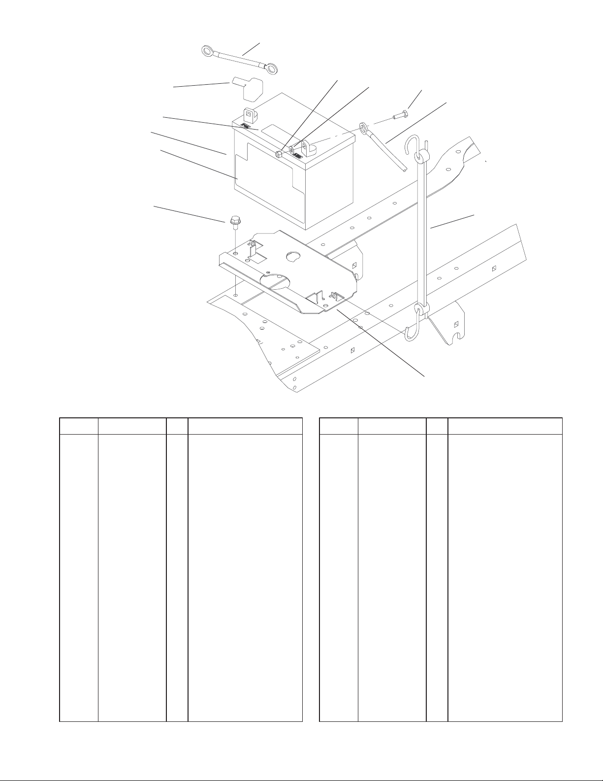
TO SOLENOID ON SINGLE
CYL ENGINE, TO STARTER
ON TWIN CYL ENGINE
2
3324–687
3
4
5
TO ENGINE BOLT
8
Battery Assembly
DescriptionPart No. Qty.Ref. No. DescriptionPart No. Qty.Ref. No.
1 100–4186 1 Battery Cable–Red
2 3296–42 2 Nut–Lock, NI
3 3256–22 2 Washer–Flat
4 321–5 2 Screw–HH
5 111078 1 Wire – Black
6 104–2467 1 Hold–Down, Battery
7 104–5016–03 1 Plate–Battery
8 32144–14 2 Screw–HWH
9 104–2491 1 Battery
9:1 104–4163 1 Decal–Battery
9:2 104–5091 1 Decal–Battery
10 28–8080 1 Boot–Terminal
6
7
Sheet No.:6
7
3324–687
1
1:3
10
9
8
7
6
5
2
2:2
2:1
3
4
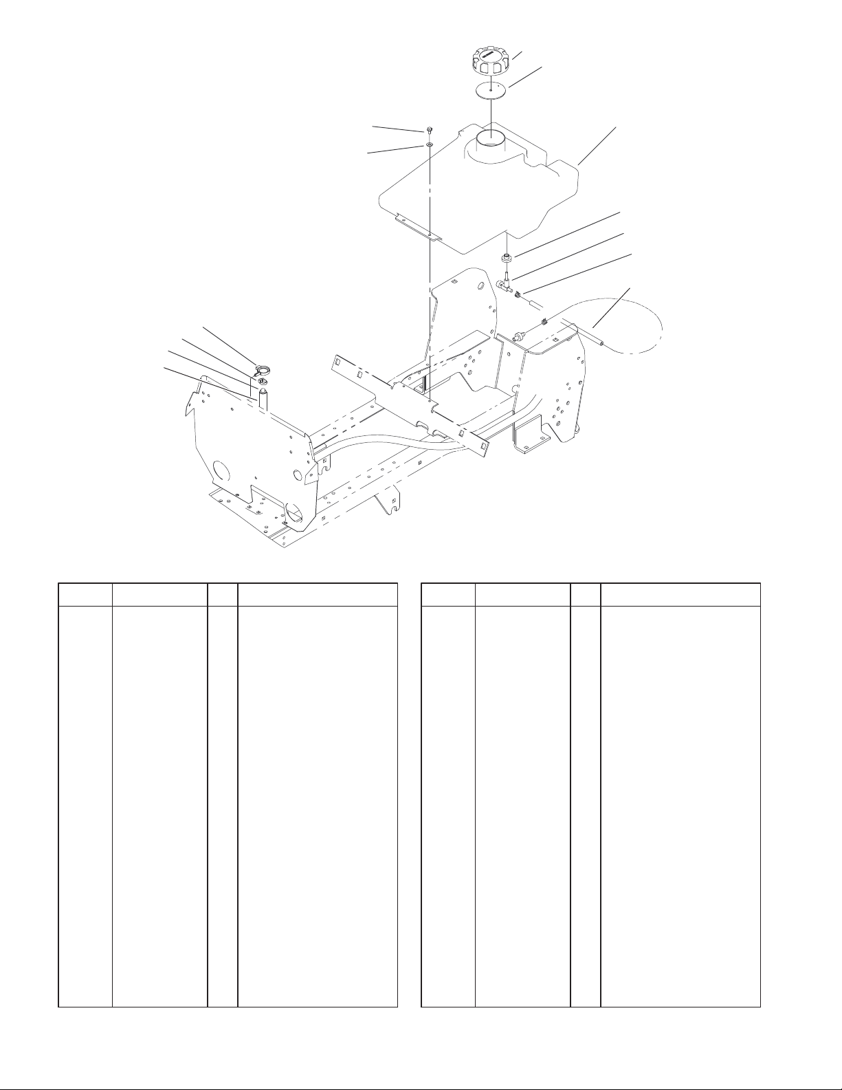
Fuel Tank Assembly
DescriptionPart No. Qty.Ref. No. DescriptionPart No. Qty.Ref. No.
1 88–3980 1 Gas Cap ASM
1:3 88–4010 1 Gasket–Cap, Gas
2 94–6928 1 Tank – Gas
2:1 104048 1 Valve–Fuel
2:2 104047 1 Bushing
3 2412–98 2 Clamp
4 92–6754 1 Hose – Fuel Line
5 100–6072 1 Hose–Breather
6 93–3817 1 Fitting–Vent
7 2412–119 1 Clamp–Worm
8 104–2490 1 Clamp–Hose
9 3256–22 2 Washer–Flat
10 32144–4 2 Screw–HWH
Sheet No.:7
8
3324–687
7:1
5
4
3
2
1
11
12
6
7
8
9
10
Sheet No.:8
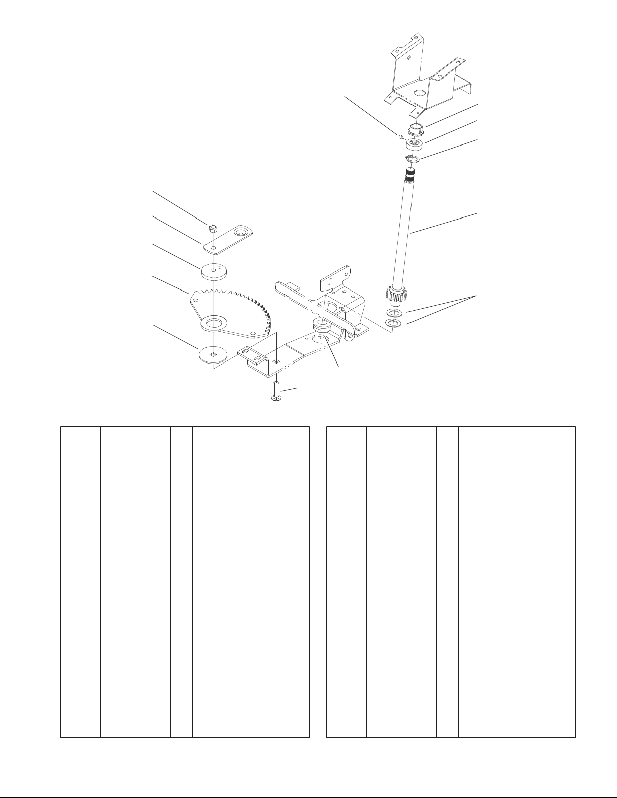
Lower Steering Assembly
DescriptionPart No. Qty.Ref. No. DescriptionPart No. Qty.Ref. No.
1 111419 1 Bearing–Washer
2 78–2610 1 Gear–Sector
3 111418 1 Bushing
4 78–9150–03 1 Plate
5 108881 1 Nut
6 109189 1 Bearing–Flanged
7 111383 1 Collar
7:1 3245–32 1 Screw–HS
8 111646 1 Ring–Retaining
9 92–6702 1 Shaft–Lower Steering
10 1278 2 Washer
11 110391 1 Bearing–Wheel
12 3231–4 1 Screw–CARR
9
3324–687
8
9
23
12
6:1
10
11
Sheet No.:9
7
6
5
4
3
2
1
13
14
22
16
21
19
20
15
16
17
18
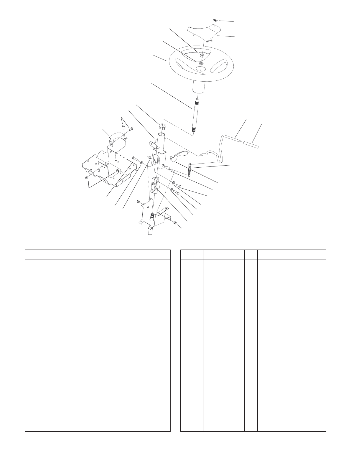
Steering Wheel and Tilt Assembly
DescriptionPart No. Qty.Ref. No. DescriptionPart No. Qty.Ref. No.
1 92–6777–03 1 Bracket – Support
Column
2 321–4 4 Screw–HH
3 93–1148–03 1 Column
4 93–1146 1 Bushing–Upper,
Steering
5 94–2874 1 Shaft–Short, Steering
6 98–1471 1 Wheel–Steering (only
on: 72052)
6 98–1472 1 Wheel – Steering, Toro
(only on: 72072)
6:1 98–1468 1 Cover–Wheel,
Steering
7 3253–7 1 Washer–Lock
8 3217–9 1 Nut–HH
9 98–1459 1 Decal–Toro
10 92–6971 1 Lever – Tilt
11 92–6798 1 Cap–Rod, Tilt
12 93–1357 1 Spring – Extension,
Steering
13 92–6776 1 Bracket – Detent
14 92–6999 1 Spacer – Yoke
15 322–3 1 Screw–HH
16 3256–23 2 Washer–Flat
17 33114–030 2 Screw–HH
18 3253–4 2 Washer–Lock
19 92–6717 1 U Joint – Steering
20 3296–29 2 Nut–Lock
21 92–6998 1 Spacer – Yoke Right
22 322–17 1 Screw–HH
23 3296–8 4 Nut–Lock NI
10
22
21
20
3
19
18
28
17
3324–687
7
24
8
9
1
12:1
12:2
1
33
12
29
30
WIRE
31
32
27
5
6
4
1
2
3 4
23
26
25
26
PTO CLUTCH
16
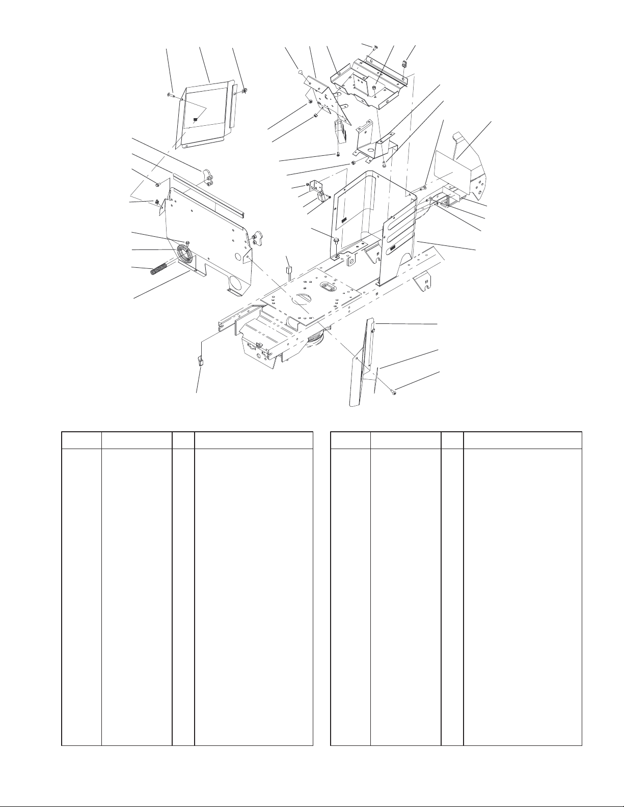
Hoodstand and Firewall Assembly
DescriptionPart No. Qty.Ref. No. DescriptionPart No. Qty.Ref. No.
1 92–7020 9 Screw–HH
2 92–6937–03 1 Cover–RH Side
3 92–7006 4 Nut
4 3229–11 4 Screw–CARR
5 104–5015–03 1 Panel–Support, Dash
6 92–6859–03 1 Support – Dash
7 107069 4 Clip
8 92–6778–03 1 Bracket–Lower
Column
9 321–4 4 Screw–HH
12 1 Hoodstand ASM (only
on: 72052)
12 104–5062 1 Hoodstand ASM W/
Decals (He) (only on:
72072)
12:1 83–6620 1 Decal – Instruction
12:2 93–7313 1 Decal–Slope/Hydro
(only on: 72072)
12:2 93–0302 1 Decal – Danger (only
on: 72052)
13 92–6936–03 1 Cover–LH Side
14 104–4694 2 Decal–266 Hydro
16 212–93 1 Clamp–Casing
17 104–0818–03 1 Firewall
18 24–7924 2 Cover–Drive Shaft
19 32144–4 2 Screw–HWH
13
14
1
Sheet No.:10
20 46–8093 2 Screw–Plastite
21 93–1131 1 Trim–Seal Firewall
22 92–6960 2 Latch – Hood
23 32149–2 2 Nut
24 3296–8 4 Nut–Lock NI
25 32144–8 2 Screw–HH
26 3296–42 3 Nut–Lock, NI
27 32144–14 2 Screw–HWH
28 104–2458 1 Wire Harness–266h
29 3296–1 2 Nut–Lock NI
30 104–0833–03 1 Bracket–Parking
Brake
31 95–1653 1 Switch – Single Pole
32 3290–392 2 Screw – HHF
33 32104–118 2 Screw–PPH
11
3324–687
41
40
39
15
38
14
37
32
35
6
5
4
14
7 8
45
44
9
43
42
15
10
11
12
13
23
14
21
22
15
16
17
18
19
20
34
36
33
31
22
30
29
28
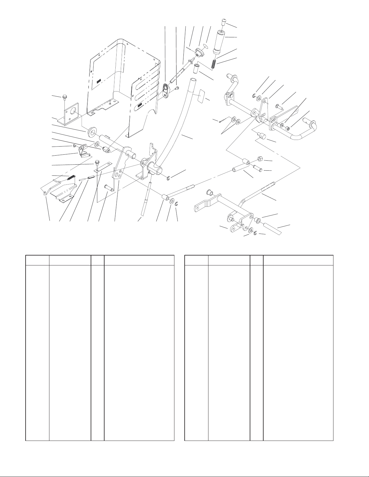
Lift Lever Arm and Height–Of–Cut Assembly
DescriptionPart No. Qty.Ref. No. DescriptionPart No. Qty.Ref. No.
4 92–6794 1 Wedge – HOC
5 32144–4 1 Screw–HWH
6 92–6965 1 Rod – HOC
7 933141 1 Pin–Spirol
8 115593 1 Knob
9 78–9740 1 Decal–Height Knob
10 92–6711 1 Tip – Rod
11 92–6710 1 Grip – Handle
12 933148 1 Pin–Spirol
13 3624 1 Spring–Compression
14 32120–47 5 Ring–Retaining
15 3256–26 6 Washer–Flat
16 79–3401–03 1 Shaft–Gage
17 3231–25 2 Screw–CARR
18 3256–24 2 Washer–Flat
19 3296–39 2 Nut–Lock, NI
20 8870 1 Rod–Trunnion Lift
21 3296–23 1 Nut–Lock, NI
22 79–1250 2 Pin
23 78–7390 1 Tube
24 78–2431 1 Rod
25 94–4944 1 Shaft – Pedal Pivot
26 256–90 2 Bushing–Flange
27 92–6855–03 1 Arm–Pivot
28 78–7360 1 Rod
29 92–6977–03 1 Rod – Lift Lever
24
26
1415
27
15
14
25
Sheet No.:11
30 94–3552–03 1 Shaft–Lift
31 78–6810–03 1 Plate
32 32144–14 2 Screw–HWH
33 32121–25 1 Pin–Roll
34 92–6978 1 Rod – HOC Indicator
35 92–7007 1 Spring – Extension
36 32121–103 1 Pin–Spring
37 92–6979 1 Plate – HOC Gage
38 78–2140 1 Trunnion
39 106269 1 Bearing–Flange
40 93–0523–03 1 Bracket–Pivot,
Linkage
41 32144–14 2 Screw–HWH
42 8130 1 Retainer–Spring
43 112168 1 Decal–Lift (only on:
72052)
43 93–7323 1 Decal – Lift Int’l (only
on: 72072)
44 3272–6 1 Pin–Cotter
45 94–3761–03 1 Lever–Lift
12
 Loading...