

Page 1

FORM NO. 3321–862
LAWN & GARDEN TRACTOR
260 Series
SET UP
INSTRUCTIONS
Loose Parts
Note: Use the chart below to identify parts for assembly.
DESCRIPTION QTY. USE
Bolt 1/4–20 x 3/4”
Washer
Locknut 1/4–20
Key 1 Use in ignition switch.
Operator’s Manual 1 Read manual before operating tractor.
2
2
2
Attach battery cables.
Check Tire Pressure
Check front and rear tire pressure. See Operator’s
Manual for specification.
Pressure: 20 psi (138 kPa) front and rear.
POTENTIAL HAZARD
• Battery electrolyte contains sulfuric acid
which is a deadly poison and it causes
severe burns.
Activate the Battery
Bulk electrolyte with 1.260 specific gravity must be
purchased from a local battery supply outlet.
1. Remove the battery from the tractor: refer to
Operator’s Manual, Removing the Battery.
IMPORTANT: Be careful not to damage the
long vent tube when removing the battery
box.
The Toro Company – 1998
Printed in USA
All Rights Reserved
WHAT CAN HAPPEN
• If you carelessly drink electrolyte you could
die or if it gets onto your skin you will be
burned.
HOW TO AVOID THE HAZARD
• Do not drink electrolyte and avoid contact
with skin, eyes or clothing. Wear safety
glasses to shield your eyes and rubber
gloves to protect your hands.
• Fill the battery where clean water is always
available for flushing the skin.
• Follow all instructions and comply with all
safety messages on the electrolyte container.
Page 2
Set Up Instructions
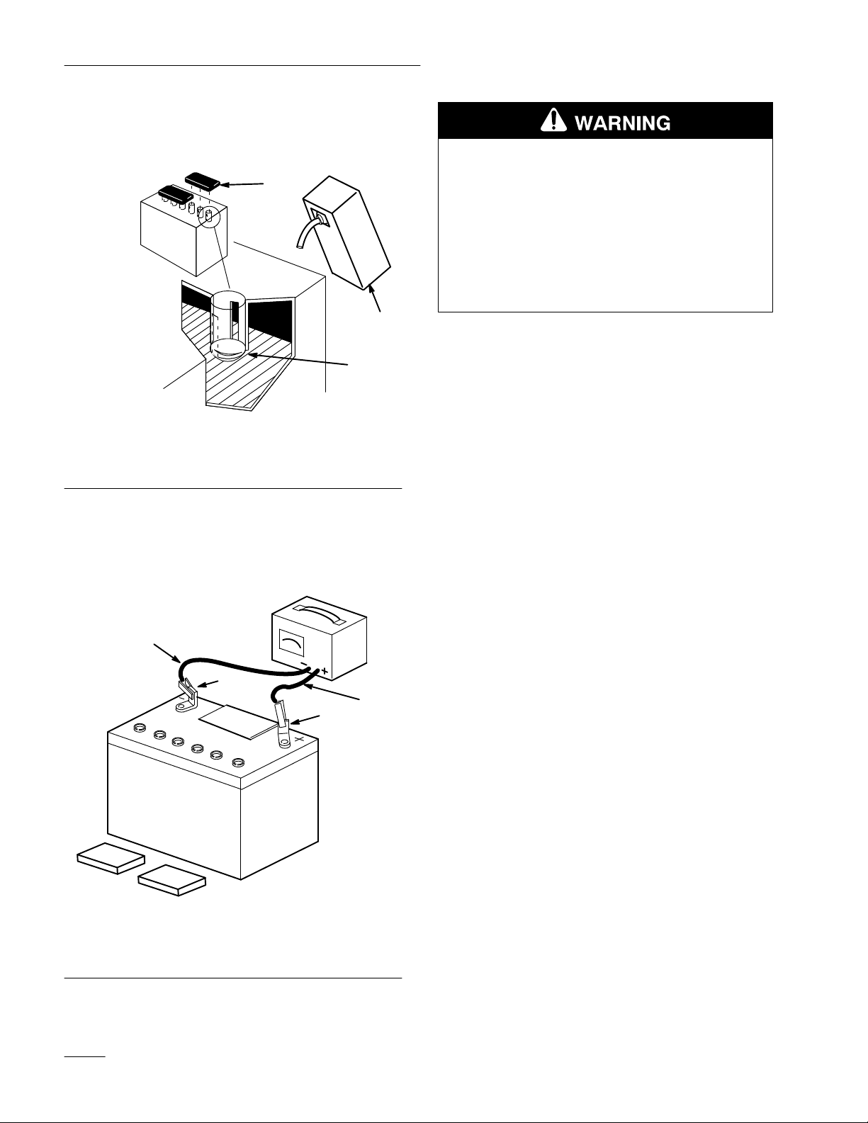
2. Remove filler caps from the battery. Slowly pour
electrolyte into each cell until the electrolyte
level is up to the lower part of the tube (Fig. 1).
1
2
3
POTENTIAL HAZARD
• Charging battery produces gasses.
WHAT CAN HAPPEN
• Battery gasses can explode.
HOW TO AVOID THE HAZARD
• Keep cigarettes, sparks and flames away
from battery.
4. When the battery is fully charged, disconnect the
charger from the electrical outlet then from the
negative and positive battery posts (Fig. 2).
Figure 1
1. Filler caps
2. Electrolyte
3. Lower part of the tube
3. Leave the covers off and connect a 3 to 4 amp
battery charger to the battery posts (Fig. 2).
Charge the battery at a rate of 4 amperes or less
for 4 hours (12 volts).
4
2
3
1
1262
5. Slowly pour electrolyte into each cell until the
level is once again up to the “UPPER” line on
the battery case (Fig. 1) and install covers.
6. Install the battery in the tractor and connect
cables with (2) 1/4 x 3/4” bolts, (2) washers and
(2) 1/4–20 locknuts: refer to the Operator’s
Manual, Installing the Battery.
1. Positive post
2. Negative post
2
1254
Figure 2
3. Charger red (+) wire
4. Charger black (–) wire
Page 3

Set Up Instructions
Fill Crankcase with Oil
IMPORTANT: The tractor is shipped from
the factory without oil in the engine crankcase
Refer to the Operator’s Manual, Engine Oil
Specifications for oil type, viscosity, and crankcase
capacity. Only add about 80% of the specified amount
of oil. Then check the oil level and add only enough
oil to raise the level to the “FULL” mark on the
dipstick.
Note: When checking oil, slide the dipstick
fully into the filler tube, do not thread
onto fill tube.
Lubricate the Tractor
Refer to the Operator’s Manual, Greasing and
Lubrication.
If equipped with Power Lift, check reservoir level. If
necessary, fill to bottom of filler opening with Dexron
Type II
Check Safety System
Adjust Electric Clutch
The electric clutch has three (3) adjustment nuts that
all must be adjusted the same (Fig. 3).
1. Insert a 0.010 inch (.25 mm) feeler gauge into
the slot (Fig. 3).
2. Turn the nut until light resistance is felt on the
gauge.
3. Repeat for all three adjusting nuts.
3
2
m–3159
Figure 3
1. Slot
2. 0.010” (25 mm) Feeler
gauge
3. Adjusting nut
1
Refer to the Operator’s Manual, Checking Safety
System.
Electric Clutch Break-In
The electric clutch requires initial break-in to seat the
mating surfaces. Engage/disengage the clutch 10-20
cycles with the mower installed. Rotating the blades
provides load for break-in.
Test Drive the Tractor
Make sure all electrical and mechanical systems are
operating properly.
3
Page 4

 Loading...