

Page 1

260 Series Tractor
Service
Manual
Page 2

ABOUT THIS MANUAL
This service manual was written expressly for Toro service technicians. The Toro Company
has made every effort to make the information in this manual complete and correct.
Basic shop safety knowledge and mechanical/electrical skills are assumed. The Table of
Contents lists the systems and the related topics covered in this manual.
For additional information on the electrical system, please refer to the Toro Electrical
Demystification Guide (492-4404). For service information on drive systems, please refer to
the appropriate service manual: Tuff Torq (492-0699), Hydro-Gear (492-0682), Peerless
(contact Tecumseh Products). For information specific to the engines used on this unit, refer
to the appropriate engine manufacturer’s service and repair instructions.
Tractor model years 1994 - 2002 are covered in this manual. The manual may also be
specified for use on later model products.
The hydrostatic transaxle is a sophisticated piece of machinery. Maintain strict cleanliness
control during all stages of service and repair. Cover or cap all hose ends and fittings
whenever they are exposed. Even a small amount of dirt or other contamination can
severely damage the system.
We are hopeful that you will find this manual a valuable addition to your service shop. If you
have questions or comments regarding this manual, please contact us at the following
address:
The Toro Company
Consumer Service Department
8111 Lyndale Avenue South
Bloomington, MN 55420-1196
The Toro Company reserves the right to change product specifications or this manual
without notice.
Copyright© All Rights Reserved
©2002 The Toro Company
Page 3

SPECIFICATIONS
General Specifications . . . . . . . . . . . . . . . . . . . . . . . . . . . . . . . . . . . . . . . . . . . . . . .1 - 1
Tecumseh Peerless Transaxle . . . . . . . . . . . . . . . . . . . . . . . . . . . . . . . . . . . . . . . . .1 - 2
Identification: Tecumseh Peerless Model 820-024 . . . . . . . . . . . . . . . . . . . . . . .1 - 2
General Specifications . . . . . . . . . . . . . . . . . . . . . . . . . . . . . . . . . . . . . . . . . . . . .1 - 2
Hydrostatic Transaxles . . . . . . . . . . . . . . . . . . . . . . . . . . . . . . . . . . . . . . . . . . . . . . .1 - 3
Identification: Tuff Torq Model K61A Transaxle . . . . . . . . . . . . . . . . . . . . . . . . .1 - 3
General Specifications . . . . . . . . . . . . . . . . . . . . . . . . . . . . . . . . . . . . . . . . . . . . .1 - 3
Identification: Hydro-Gear Model 322-3000 & 330-3000 Transaxle . . . . . . . . . .1 - 4
General Specifications . . . . . . . . . . . . . . . . . . . . . . . . . . . . . . . . . . . . . . . . . . . . .1 - 4
Torque Specifications . . . . . . . . . . . . . . . . . . . . . . . . . . . . . . . . . . . . . . . . . . . . . . . .1 - 5
Fastener Identification . . . . . . . . . . . . . . . . . . . . . . . . . . . . . . . . . . . . . . . . . . . . .1 - 5
Standard Torque for Dry, Zinc Plated, and Steel Fasteners (Inch Series) . . . . . . . .1 - 6
Standard Torque for Dry, Zinc, and Steel Fasteners (Metric Fasteners) . . . . . . . . .1 - 7
Other Torque Specifications . . . . . . . . . . . . . . . . . . . . . . . . . . . . . . . . . . . . . . . . . . .1 - 8
SAE Grade 8 Steel Set Screws . . . . . . . . . . . . . . . . . . . . . . . . . . . . . . . . . . . . . .1 - 8
Thread Cutting Screws (Zinc Plated Steel) . . . . . . . . . . . . . . . . . . . . . . . . . . . . .1 - 8
Conversion Factors . . . . . . . . . . . . . . . . . . . . . . . . . . . . . . . . . . . . . . . . . . . . . . .1 - 8
Wheel Bolts and Lug Nuts . . . . . . . . . . . . . . . . . . . . . . . . . . . . . . . . . . . . . . . . . .1 - 8
Thread Cutting Screws (Zinc Plated Steel) . . . . . . . . . . . . . . . . . . . . . . . . . . . . .1 - 8
Equivalents and Conversions . . . . . . . . . . . . . . . . . . . . . . . . . . . . . . . . . . . . . . . . . .1 - 9
Decimal and Millimeter Equivalents. . . . . . . . . . . . . . . . . . . . . . . . . . . . . . . . . . . .1 - 9
U.S. to Metric Conversions . . . . . . . . . . . . . . . . . . . . . . . . . . . . . . . . . . . . . . . . .1 - 10
TABLE OF CONTENTS
CHASSIS
Model and Serial Number Location . . . . . . . . . . . . . . . . . . . . . . . . . . . . . . . . . . . . .2 - 1
Greasing and Lubrication . . . . . . . . . . . . . . . . . . . . . . . . . . . . . . . . . . . . . . . . . . . . .2 - 1
Front Wheel Toe-in . . . . . . . . . . . . . . . . . . . . . . . . . . . . . . . . . . . . . . . . . . . . . . . . . .2 - 2
Front Wheel Toe-in Adjustment . . . . . . . . . . . . . . . . . . . . . . . . . . . . . . . . . . . . . . . .2 - 3
Front Wheel and Spindle Removal and Installation . . . . . . . . . . . . . . . . . . . . . . . . .2 - 3
Front Axle Removal and Installation . . . . . . . . . . . . . . . . . . . . . . . . . . . . . . . . . . . . .2 - 4
Steering Gear . . . . . . . . . . . . . . . . . . . . . . . . . . . . . . . . . . . . . . . . . . . . . . . . . . . . . .2 - 6
Steering Backlash Adjustment . . . . . . . . . . . . . . . . . . . . . . . . . . . . . . . . . . . . . . . . .2 - 6
Steering Gear Shaft Disassembly . . . . . . . . . . . . . . . . . . . . . . . . . . . . . . . . . . . . . . .2 - 7
Steering Gear Assembly . . . . . . . . . . . . . . . . . . . . . . . . . . . . . . . . . . . . . . . . . . . . .2 - 10
Sector Gear Disassembly . . . . . . . . . . . . . . . . . . . . . . . . . . . . . . . . . . . . . . . . . . . .2 - 11
Sector Gear Assembly . . . . . . . . . . . . . . . . . . . . . . . . . . . . . . . . . . . . . . . . . . . . . .2 - 12
Tilt Steering . . . . . . . . . . . . . . . . . . . . . . . . . . . . . . . . . . . . . . . . . . . . . . . . . . . . . . .2 - 12
Tilt Steering Disassembly . . . . . . . . . . . . . . . . . . . . . . . . . . . . . . . . . . . . . . . . . . . .2 - 13
Tilt Steering Assembly . . . . . . . . . . . . . . . . . . . . . . . . . . . . . . . . . . . . . . . . . . . . . .2 - 14
Steering Specifications . . . . . . . . . . . . . . . . . . . . . . . . . . . . . . . . . . . . . . . . . . . . . .2 - 15
Hood Removal . . . . . . . . . . . . . . . . . . . . . . . . . . . . . . . . . . . . . . . . . . . . . . . . . . . .2 - 16
Seat and Fender Removal . . . . . . . . . . . . . . . . . . . . . . . . . . . . . . . . . . . . . . . . . . .2 - 16
Removal . . . . . . . . . . . . . . . . . . . . . . . . . . . . . . . . . . . . . . . . . . . . . . . . . . . . . . . .2 - 3
Description . . . . . . . . . . . . . . . . . . . . . . . . . . . . . . . . . . . . . . . . . . . . . . . . . . . . . .2 - 6
Description . . . . . . . . . . . . . . . . . . . . . . . . . . . . . . . . . . . . . . . . . . . . . . . . . . . . .2 - 12
260 Series Tractor Service Manual iii
Page 4

TABLE OF CONTENTS
Gas Tank Removal . . . . . . . . . . . . . . . . . . . . . . . . . . . . . . . . . . . . . . . . . . . . . . . . 2 - 17
Lift Lever Linkage . . . . . . . . . . . . . . . . . . . . . . . . . . . . . . . . . . . . . . . . . . . . . . . . . 2 - 18
Dial-A-Height Linkage . . . . . . . . . . . . . . . . . . . . . . . . . . . . . . . . . . . . . . . . . . . . . . 2 - 19
Lift Arm Linkage . . . . . . . . . . . . . . . . . . . . . . . . . . . . . . . . . . . . . . . . . . . . . . . . . . 2 - 20
Adjustments . . . . . . . . . . . . . . . . . . . . . . . . . . . . . . . . . . . . . . . . . . . . . . . . . . . . . 2 - 21
Lift Height . . . . . . . . . . . . . . . . . . . . . . . . . . . . . . . . . . . . . . . . . . . . . . . . . . . . . 2 - 21
Leveling . . . . . . . . . . . . . . . . . . . . . . . . . . . . . . . . . . . . . . . . . . . . . . . . . . . . . . . 2 - 21
Side to Side . . . . . . . . . . . . . . . . . . . . . . . . . . . . . . . . . . . . . . . . . . . . . . . . . . . . 2 - 21
Power Lifts . . . . . . . . . . . . . . . . . . . . . . . . . . . . . . . . . . . . . . . . . . . . . . . . . . . . . . 2 - 21
Electrohydraulic Lift (2000 and Prior Models) . . . . . . . . . . . . . . . . . . . . . . . . . . 2 - 21
Electric Lift (2001 and Later Models) . . . . . . . . . . . . . . . . . . . . . . . . . . . . . . . . . . 2 - 21
Removal . . . . . . . . . . . . . . . . . . . . . . . . . . . . . . . . . . . . . . . . . . . . . . . . . . . . . . 2 - 21
Installation . . . . . . . . . . . . . . . . . . . . . . . . . . . . . . . . . . . . . . . . . . . . . . . . . . . . . 2 - 21
TUFF TORQ TRANSAXLE
Tuff Torq Hydrostatic Transaxle. . . . . . . . . . . . . . . . . . . . . . . . . . . . . . . . . . . . . . . . 3 - 1
Internal Service . . . . . . . . . . . . . . . . . . . . . . . . . . . . . . . . . . . . . . . . . . . . . . . . . . 3 - 1
Fluid Change . . . . . . . . . . . . . . . . . . . . . . . . . . . . . . . . . . . . . . . . . . . . . . . . . . . . 3 - 1
Transaxle Removal – Tuff Torq . . . . . . . . . . . . . . . . . . . . . . . . . . . . . . . . . . . . . . . . 3 - 1
Installation - Tuff Torq Transaxle . . . . . . . . . . . . . . . . . . . . . . . . . . . . . . . . . . . . . . 3 - 4
Belt Replacement – Tuff Torq Transaxle . . . . . . . . . . . . . . . . . . . . . . . . . . . . . . . . 3 - 6
Belt Routing . . . . . . . . . . . . . . . . . . . . . . . . . . . . . . . . . . . . . . . . . . . . . . . . . . . 3 - 10
Belt Adjustment . . . . . . . . . . . . . . . . . . . . . . . . . . . . . . . . . . . . . . . . . . . . . . . . . 3 - 13
Troubleshooting – Tuff Torq Transaxle . . . . . . . . . . . . . . . . . . . . . . . . . . . . . . . . . 3 - 14
Purging Procedures – Tuff Torq Transaxle . . . . . . . . . . . . . . . . . . . . . . . . . . . . . . 3 - 15
Brake – Tuff Torq Transaxle . . . . . . . . . . . . . . . . . . . . . . . . . . . . . . . . . . . . . . . . . 3 - 15
Checking the Brake . . . . . . . . . . . . . . . . . . . . . . . . . . . . . . . . . . . . . . . . . . . . . . 3 - 15
Adjusting the Brake – Tuff Torq Transaxle . . . . . . . . . . . . . . . . . . . . . . . . . . . . . . 3 - 15
Foot Control Adjustment Procedure . . . . . . . . . . . . . . . . . . . . . . . . . . . . . . . . . . . 3 - 16
Neutral Adjustment – Tuff Torq Transaxle . . . . . . . . . . . . . . . . . . . . . . . . . . . . . . 3 - 17
iv 260 Series Tractor Service Manual
Page 5

HYDRO-GEAR TRANSAXLE
Hydro-Gear Hydrostatic Transaxle . . . . . . . . . . . . . . . . . . . . . . . . . . . . . . . . . . . . . .4 - 1
Internal Service . . . . . . . . . . . . . . . . . . . . . . . . . . . . . . . . . . . . . . . . . . . . . . . . . . .4 - 1
Fluid Change . . . . . . . . . . . . . . . . . . . . . . . . . . . . . . . . . . . . . . . . . . . . . . . . . . . .4 - 1
Transaxle Removal - Hydro-Gear . . . . . . . . . . . . . . . . . . . . . . . . . . . . . . . . . . . . . . .4 - 1
Installation - Hydro-gear Transaxle . . . . . . . . . . . . . . . . . . . . . . . . . . . . . . . . . . . . . .4 - 4
Belt Adjustment . . . . . . . . . . . . . . . . . . . . . . . . . . . . . . . . . . . . . . . . . . . . . . . . . . . . .4 - 7
Purging Procedures – Hydro-Gear Transaxle . . . . . . . . . . . . . . . . . . . . . . . . . . . . .4 - 8
Brake – Hydro-Gear Transaxle . . . . . . . . . . . . . . . . . . . . . . . . . . . . . . . . . . . . . . . . .4 - 9
Checking the Brake . . . . . . . . . . . . . . . . . . . . . . . . . . . . . . . . . . . . . . . . . . . . . . .4 - 9
Brake Adjustment – Hydro-Gear Transaxle . . . . . . . . . . . . . . . . . . . . . . . . . . . . . . .4 - 9
Foot Control Adjustment Procedure . . . . . . . . . . . . . . . . . . . . . . . . . . . . . . . . . . . .4 - 10
Troubleshooting Chart for the Hydro-Gear Transaxle . . . . . . . . . . . . . . . . . . . . . .4 - 11
Belt Replacement – Hydro-Gear Transaxle . . . . . . . . . . . . . . . . . . . . . . . . . . . . . .4 - 11
Belt Routing Diagram . . . . . . . . . . . . . . . . . . . . . . . . . . . . . . . . . . . . . . . . . . . . .4 - 15
Belt Adjustment . . . . . . . . . . . . . . . . . . . . . . . . . . . . . . . . . . . . . . . . . . . . . . . . . .4 - 16
Neutral Adjustment – Hydro-Gear Transaxle . . . . . . . . . . . . . . . . . . . . . . . . . . . . .4 - 17
GEAR DRIVE
Transaxle Removal – Gear Drive . . . . . . . . . . . . . . . . . . . . . . . . . . . . . . . . . . . . . . .5 - 1
Installation – Gear Drive Transaxle . . . . . . . . . . . . . . . . . . . . . . . . . . . . . . . . . . . . .5 - 3
Troubleshooting . . . . . . . . . . . . . . . . . . . . . . . . . . . . . . . . . . . . . . . . . . . . . . . . . . . .5 - 5
Internal Service . . . . . . . . . . . . . . . . . . . . . . . . . . . . . . . . . . . . . . . . . . . . . . . . . . . . .5 - 5
Symptom: Unit Jumps Out Of Gear . . . . . . . . . . . . . . . . . . . . . . . . . . . . . . . . . . . . .5 - 6
Symptom: Unit Can Not Be Shifted (or Difficult to Shift) . . . . . . . . . . . . . . . . . . . . .5 - 6
Symptom: Unit Does Not Drive . . . . . . . . . . . . . . . . . . . . . . . . . . . . . . . . . . . . . . . .5 - 6
Belt Replacement – Gear Drive . . . . . . . . . . . . . . . . . . . . . . . . . . . . . . . . . . . . . . . .5 - 7
Belt Routing Diagram . . . . . . . . . . . . . . . . . . . . . . . . . . . . . . . . . . . . . . . . . . . . . .5 - 9
Belt Adjustment . . . . . . . . . . . . . . . . . . . . . . . . . . . . . . . . . . . . . . . . . . . . . . . . . . . .5 - 12
Proper Shifting Procedures - Gear Drive . . . . . . . . . . . . . . . . . . . . . . . . . . . . . . . .5 - 13
Shift Linkage Adjustment . . . . . . . . . . . . . . . . . . . . . . . . . . . . . . . . . . . . . . . . . . . .5 - 13
Shift Detent Tension Adjustment . . . . . . . . . . . . . . . . . . . . . . . . . . . . . . . . . . . . . .5 - 14
Brakes . . . . . . . . . . . . . . . . . . . . . . . . . . . . . . . . . . . . . . . . . . . . . . . . . . . . . . . . . . .5 - 14
Checking the Brake . . . . . . . . . . . . . . . . . . . . . . . . . . . . . . . . . . . . . . . . . . . . . .5 - 14
Adjusting the Brake . . . . . . . . . . . . . . . . . . . . . . . . . . . . . . . . . . . . . . . . . . . . . . . . .5 - 15
TABLE OF CONTENTS
260 Series Tractor Service Manual v
Page 6

TABLE OF CONTENTS
ELECTRICAL SYSTEMS
Gear Drive Models . . . . . . . . . . . . . . . . . . . . . . . . . . . . . . . . . . . . . . . . . . . . . . . . . 6 - 1
Hydrostatic Models . . . . . . . . . . . . . . . . . . . . . . . . . . . . . . . . . . . . . . . . . . . . . . . . . 6 - 1
Relay . . . . . . . . . . . . . . . . . . . . . . . . . . . . . . . . . . . . . . . . . . . . . . . . . . . . . . . . . . . . 6 - 1
Purpose . . . . . . . . . . . . . . . . . . . . . . . . . . . . . . . . . . . . . . . . . . . . . . . . . . . . . . . . 6 - 1
Location . . . . . . . . . . . . . . . . . . . . . . . . . . . . . . . . . . . . . . . . . . . . . . . . . . . . . . . 6 - 1
How It Works . . . . . . . . . . . . . . . . . . . . . . . . . . . . . . . . . . . . . . . . . . . . . . . . . . . . 6 - 1
Testing . . . . . . . . . . . . . . . . . . . . . . . . . . . . . . . . . . . . . . . . . . . . . . . . . . . . . . . . 6 - 2
Solenoid . . . . . . . . . . . . . . . . . . . . . . . . . . . . . . . . . . . . . . . . . . . . . . . . . . . . . . . . . 6 - 2
Purpose . . . . . . . . . . . . . . . . . . . . . . . . . . . . . . . . . . . . . . . . . . . . . . . . . . . . . . . . 6 - 2
Location . . . . . . . . . . . . . . . . . . . . . . . . . . . . . . . . . . . . . . . . . . . . . . . . . . . . . . . 6 - 3
How it Works . . . . . . . . . . . . . . . . . . . . . . . . . . . . . . . . . . . . . . . . . . . . . . . . . . . . 6 - 3
Testing . . . . . . . . . . . . . . . . . . . . . . . . . . . . . . . . . . . . . . . . . . . . . . . . . . . . . . . . 6 - 3
Ignition Switch . . . . . . . . . . . . . . . . . . . . . . . . . . . . . . . . . . . . . . . . . . . . . . . . . . . . . 6 - 4
Purpose . . . . . . . . . . . . . . . . . . . . . . . . . . . . . . . . . . . . . . . . . . . . . . . . . . . . . . . . 6 - 4
Location . . . . . . . . . . . . . . . . . . . . . . . . . . . . . . . . . . . . . . . . . . . . . . . . . . . . . . . . 6 - 4
How It Works . . . . . . . . . . . . . . . . . . . . . . . . . . . . . . . . . . . . . . . . . . . . . . . . . . . . 6 - 4
Testing . . . . . . . . . . . . . . . . . . . . . . . . . . . . . . . . . . . . . . . . . . . . . . . . . . . . . . . . . 6 - 5
Low Voltage Module . . . . . . . . . . . . . . . . . . . . . . . . . . . . . . . . . . . . . . . . . . . . . . . . 6 - 5
Purpose . . . . . . . . . . . . . . . . . . . . . . . . . . . . . . . . . . . . . . . . . . . . . . . . . . . . . . . . 6 - 5
Location . . . . . . . . . . . . . . . . . . . . . . . . . . . . . . . . . . . . . . . . . . . . . . . . . . . . . . . 6 - 5
How It Works . . . . . . . . . . . . . . . . . . . . . . . . . . . . . . . . . . . . . . . . . . . . . . . . . . . . 6 - 5
Testing . . . . . . . . . . . . . . . . . . . . . . . . . . . . . . . . . . . . . . . . . . . . . . . . . . . . . . . . 6 - 6
Electric (PTO) Clutch . . . . . . . . . . . . . . . . . . . . . . . . . . . . . . . . . . . . . . . . . . . . . . . 6 - 6
Purpose . . . . . . . . . . . . . . . . . . . . . . . . . . . . . . . . . . . . . . . . . . . . . . . . . . . . . . . . 6 - 6
Location . . . . . . . . . . . . . . . . . . . . . . . . . . . . . . . . . . . . . . . . . . . . . . . . . . . . . . . 6 - 6
How It Works . . . . . . . . . . . . . . . . . . . . . . . . . . . . . . . . . . . . . . . . . . . . . . . . . . . . 6 - 6
Testing . . . . . . . . . . . . . . . . . . . . . . . . . . . . . . . . . . . . . . . . . . . . . . . . . . . . . . . . 6 - 6
Coil Resistance Measurement . . . . . . . . . . . . . . . . . . . . . . . . . . . . . . . . . . . . . . 6 - 6
Measuring Clutch Current Draw . . . . . . . . . . . . . . . . . . . . . . . . . . . . . . . . . . . . . 6 - 7
Setting the Air Gap on 1999 and Prior Model 260 Series Tractors . . . . . . . . . . . 6 - 8
Clutch Burnishing Procedure . . . . . . . . . . . . . . . . . . . . . . . . . . . . . . . . . . . . . . . 6 - 8
PTO Switch . . . . . . . . . . . . . . . . . . . . . . . . . . . . . . . . . . . . . . . . . . . . . . . . . . . . . . . 6 - 8
Purpose . . . . . . . . . . . . . . . . . . . . . . . . . . . . . . . . . . . . . . . . . . . . . . . . . . . . . . . . 6 - 8
Location . . . . . . . . . . . . . . . . . . . . . . . . . . . . . . . . . . . . . . . . . . . . . . . . . . . . . . . 6 - 8
How it Works . . . . . . . . . . . . . . . . . . . . . . . . . . . . . . . . . . . . . . . . . . . . . . . . . . . . 6 - 8
Testing . . . . . . . . . . . . . . . . . . . . . . . . . . . . . . . . . . . . . . . . . . . . . . . . . . . . . . . . 6 - 8
Microswitches . . . . . . . . . . . . . . . . . . . . . . . . . . . . . . . . . . . . . . . . . . . . . . . . . . . . . 6 - 9
Purpose . . . . . . . . . . . . . . . . . . . . . . . . . . . . . . . . . . . . . . . . . . . . . . . . . . . . . . . . 6 - 9
Testing . . . . . . . . . . . . . . . . . . . . . . . . . . . . . . . . . . . . . . . . . . . . . . . . . . . . . . . . 6 - 9
Location . . . . . . . . . . . . . . . . . . . . . . . . . . . . . . . . . . . . . . . . . . . . . . . . . . . . . . 6 - 10
Neutral Switch - Plunger Type (Used on 2000 and Later Hydrostatic Models) . . . 6 - 11
Purpose . . . . . . . . . . . . . . . . . . . . . . . . . . . . . . . . . . . . . . . . . . . . . . . . . . . . . . . 6 - 11
Location . . . . . . . . . . . . . . . . . . . . . . . . . . . . . . . . . . . . . . . . . . . . . . . . . . . . . . 6 - 11
How it Works . . . . . . . . . . . . . . . . . . . . . . . . . . . . . . . . . . . . . . . . . . . . . . . . . . . 6 - 11
Testing . . . . . . . . . . . . . . . . . . . . . . . . . . . . . . . . . . . . . . . . . . . . . . . . . . . . . . . 6 - 12
vi 260 Series Tractor Service Manual
Page 7

TABLE OF CONTENTS
Brake Switch (Used on 2000 and Later Hydrostatic Models) . . . . . . . . . . . . . . . . .6 - 12
Purpose . . . . . . . . . . . . . . . . . . . . . . . . . . . . . . . . . . . . . . . . . . . . . . . . . . . . . . .6 - 12
Location . . . . . . . . . . . . . . . . . . . . . . . . . . . . . . . . . . . . . . . . . . . . . . . . . . . . . . .6 - 12
How it Works . . . . . . . . . . . . . . . . . . . . . . . . . . . . . . . . . . . . . . . . . . . . . . . . . . .6 - 12
Brake Switch Testing . . . . . . . . . . . . . . . . . . . . . . . . . . . . . . . . . . . . . . . . . . . . . . .6 - 13
Seat Switch . . . . . . . . . . . . . . . . . . . . . . . . . . . . . . . . . . . . . . . . . . . . . . . . . . . . . . .6 - 13
Purpose . . . . . . . . . . . . . . . . . . . . . . . . . . . . . . . . . . . . . . . . . . . . . . . . . . . . . . .6 - 13
Location . . . . . . . . . . . . . . . . . . . . . . . . . . . . . . . . . . . . . . . . . . . . . . . . . . . . . . .6 - 13
How It Works . . . . . . . . . . . . . . . . . . . . . . . . . . . . . . . . . . . . . . . . . . . . . . . . . . .6 - 14
Testing. . . . . . . . . . . . . . . . . . . . . . . . . . . . . . . . . . . . . . . . . . . . . . . . . . . . . . . . 6 - 13
KeyChoice™ Reverse Operating System – Used on 1999 and Later Tractors. . . .6 - 14
Testing the Key Choice™ Reverse Operating System - Unactivated . . . . . . . .6 - 14
Testing the KeyChoice™ Operating System - Activated . . . . . . . . . . . . . . . . . .6 - 14
KeyChoice™ Reverse Operating System Switch . . . . . . . . . . . . . . . . . . . . . . . . . .6 - 16
Purpose . . . . . . . . . . . . . . . . . . . . . . . . . . . . . . . . . . . . . . . . . . . . . . . . . . . . . . .6 - 16
How It Works . . . . . . . . . . . . . . . . . . . . . . . . . . . . . . . . . . . . . . . . . . . . . . . . . . .6 - 16
Testing . . . . . . . . . . . . . . . . . . . . . . . . . . . . . . . . . . . . . . . . . . . . . . . . . . . . . . . .6 - 16
Reverse Switch (Hydrostatic Models) . . . . . . . . . . . . . . . . . . . . . . . . . . . . . . . . . . .6 - 16
Purpose . . . . . . . . . . . . . . . . . . . . . . . . . . . . . . . . . . . . . . . . . . . . . . . . . . . . . . .6 - 16
Location . . . . . . . . . . . . . . . . . . . . . . . . . . . . . . . . . . . . . . . . . . . . . . . . . . . . . . .6 - 16
How It Works . . . . . . . . . . . . . . . . . . . . . . . . . . . . . . . . . . . . . . . . . . . . . . . . . . .6 - 16
Testing . . . . . . . . . . . . . . . . . . . . . . . . . . . . . . . . . . . . . . . . . . . . . . . . . . . . . . . .6 - 16
Reverse Switch (Gear Drive Tractors) . . . . . . . . . . . . . . . . . . . . . . . . . . . . . . . . . .6 - 17
Purpose . . . . . . . . . . . . . . . . . . . . . . . . . . . . . . . . . . . . . . . . . . . . . . . . . . . . . . .6 - 17
Location . . . . . . . . . . . . . . . . . . . . . . . . . . . . . . . . . . . . . . . . . . . . . . . . . . . . . . .6 - 17
How It Works . . . . . . . . . . . . . . . . . . . . . . . . . . . . . . . . . . . . . . . . . . . . . . . . . . .6 - 17
Testing . . . . . . . . . . . . . . . . . . . . . . . . . . . . . . . . . . . . . . . . . . . . . . . . . . . . . . . .6 - 17
KeyChoice™ Reverse Operating System Module. . . . . . . . . . . . . . . . . . . . . . . . . .6 - 17
Purpose . . . . . . . . . . . . . . . . . . . . . . . . . . . . . . . . . . . . . . . . . . . . . . . . . . . . . . .6 - 17
Location . . . . . . . . . . . . . . . . . . . . . . . . . . . . . . . . . . . . . . . . . . . . . . . . . . . . . . .6 - 18
How It Works . . . . . . . . . . . . . . . . . . . . . . . . . . . . . . . . . . . . . . . . . . . . . . . . . . .6 - 18
Testing - No Power to Circuit (With Module Out of Circuit) . . . . . . . . . . . . . . . . .6 - 19
Testing - Powered Circuit (With Module Out of Circuit). . . . . . . . . . . . . . . . . . . .6 - 19
260 Series Tractor Service Manual vii
Page 8

THIS PAGE INTENTIONALLY LEFT BLANK
viii 260 Series Tractor Service Manual
Page 9

SPECIFICATIONS
General Specifications
Item Specification
Engines All tractors since 1994 were manufactured with Kohler engines ranging from 14
to 20 Horsepower. For more information on servicing the engines, please
contact the Kohler Company.
Domestic Units High RPM Setting (no load) 3250 +/- 100 RPM
International Models High RPM Setting (no load) 2700 +/- 100 RPM
Fuel Capacity 3.9 Gallons (14.7 liter)
Wheel Base 49.5” (125.7cm)
Length 69.0” (175.2cm)
Width 35.5” (90.1cm) without the mower
Steering Sector and Pinion
Turning Radius 16 in. (40.6cm)
Electrical System 15 amp regulated DC alternator
Weight (Net Weight)
Model Weight
264-6 / 265-6 521 lbs. (236.3kg)
264-H / 265-H (Tuff Torq) 510 lbs. (231.3kg)
267-H / 268-H (Tuff Torq) 540 lbs. (244.9kg)
269-H / 270-H (Tuff Torq) 560 lbs. (254.0kg)
265-H/266-H (Hydro-Gear) 530 lbs. (240.4kg)
268-H (Hydro-Gear) 560 lbs. (254.0kg)
270-H (Hydro-Gear) 580 lbs. (263.0kg)
260 Series Tractor Service Manual 1 - 1
Page 10
SPECIFICATIONS
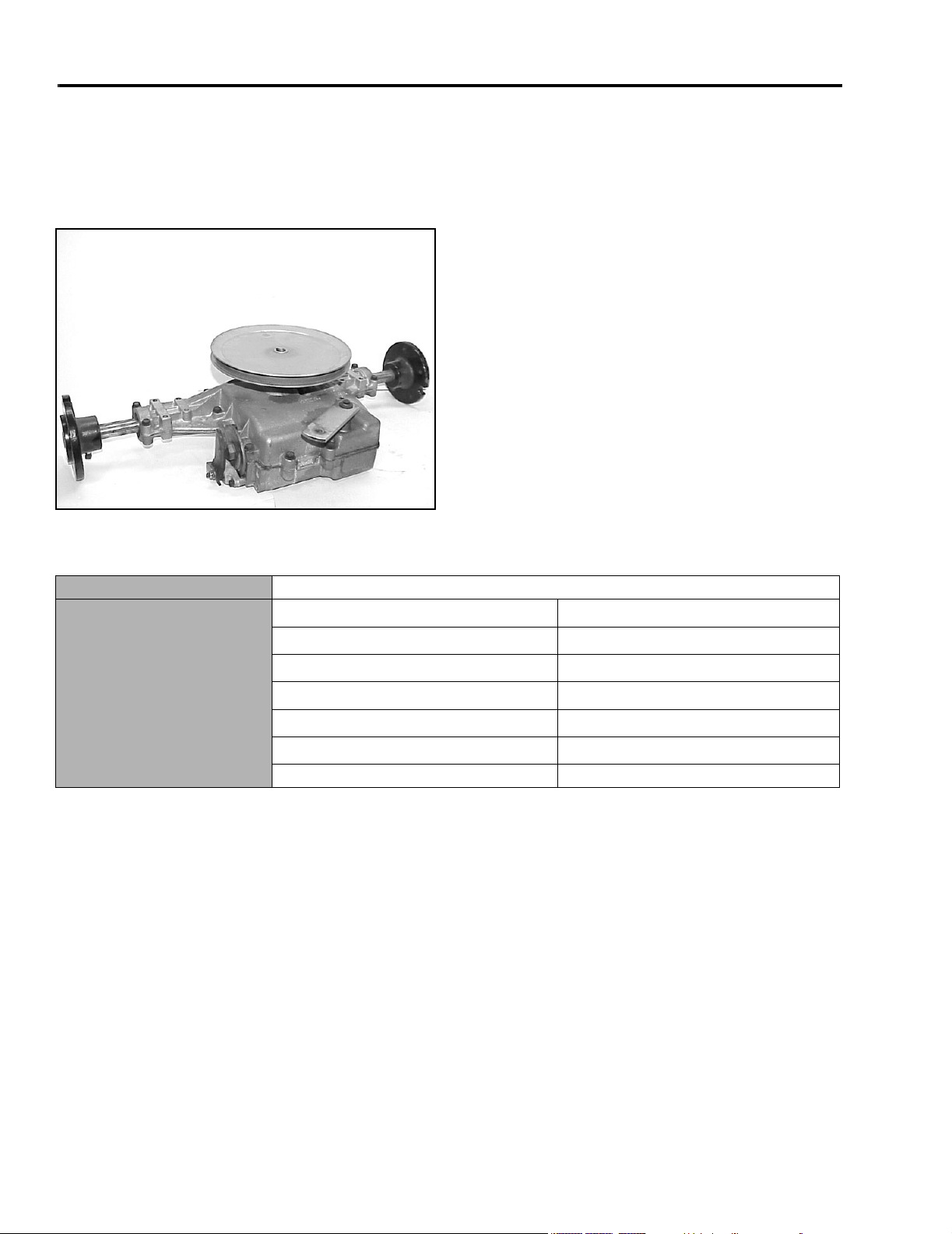
Tecumseh Peerless Transaxle
Identification:
Tecumseh Peerless Model 820-024
MVC-254X
General Specifications
Lubrication Bentonite grease (available through Tecumseh)
Ground Speed
st
Gear
1
nd
2
Gear
rd
Gear
3
th
4
Gear
th
Gear
5
th
6
Gear
Reverse 2.4 MPH (3.8km/h)
.7 MPH (1.1km/h)
1.4 MPH (2.2km/h)
2.2 MPH (3.5km/h)
3.3 MPH (5.3km/h)
4.2 MPH (6.7km/h)
5.3 MPH (8.5km/h)
1 - 2 260 Series Tractor Service Manual
Page 11
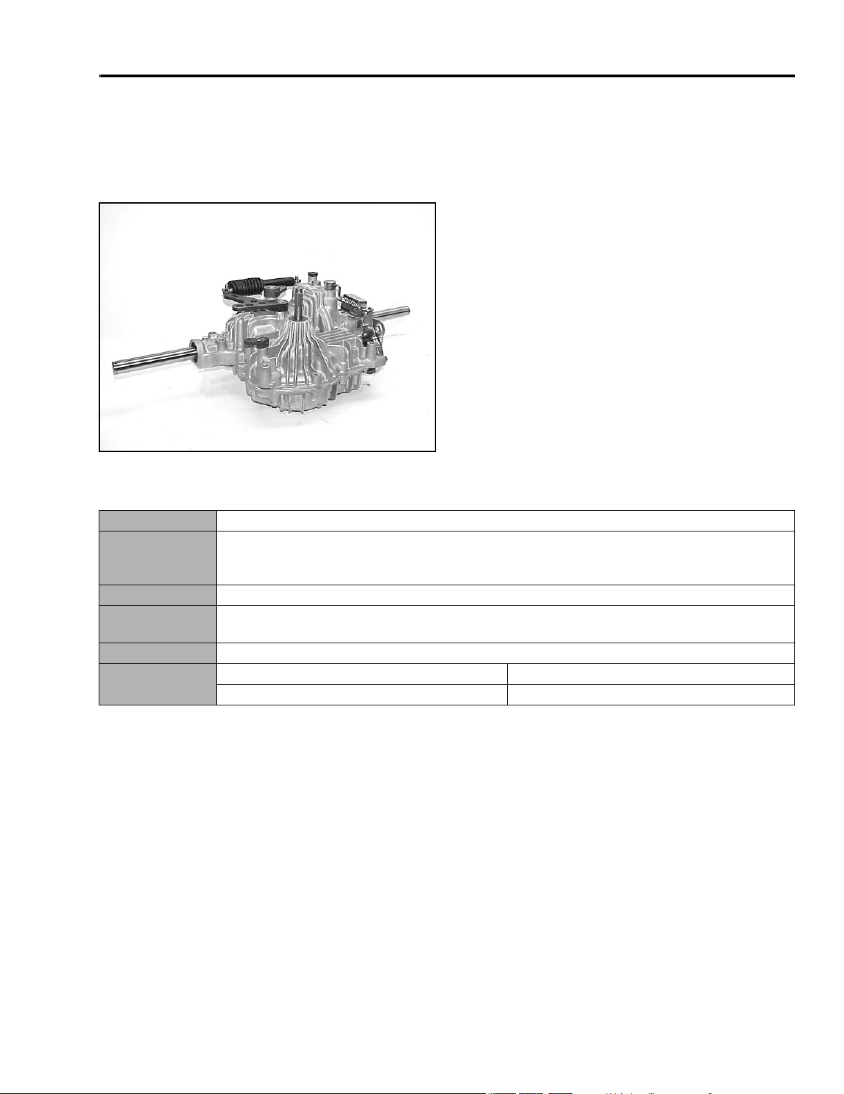
Hydrostatic Transaxles
Identification:
Tuff Torq Model K61A Transaxle
MVC-080X
SPECIFICATIONS
General Specifications
Used 1994 – 1999
Lubrication SAE 10W-30 API Service Classification SH or higher. Alternate oil: A
synthetic oil (5w50 or similar viscosity range) may be used in place of SAE 10w30. This will
permit an increase in the maximum operating temperature of approximately 18°F (10°C).
Oil Capacity 3.5 qt. (3.3 liter)
Oil Level Check when transaxle is cold. Oil should be checked at the reservoir cup, located under the
front hood, on the panel support; oil level should be at the cold mark.
Fluid Change The transaxle is factory filled and does not require regular oil changes.
Ground Speed Forward 0-5.2 MPH (0-8.3km/h)
Reverse 0-2.3 MPH (0-3.7km/h)
260 Series Tractor Service Manual 1 - 3
Page 12
SPECIFICATIONS
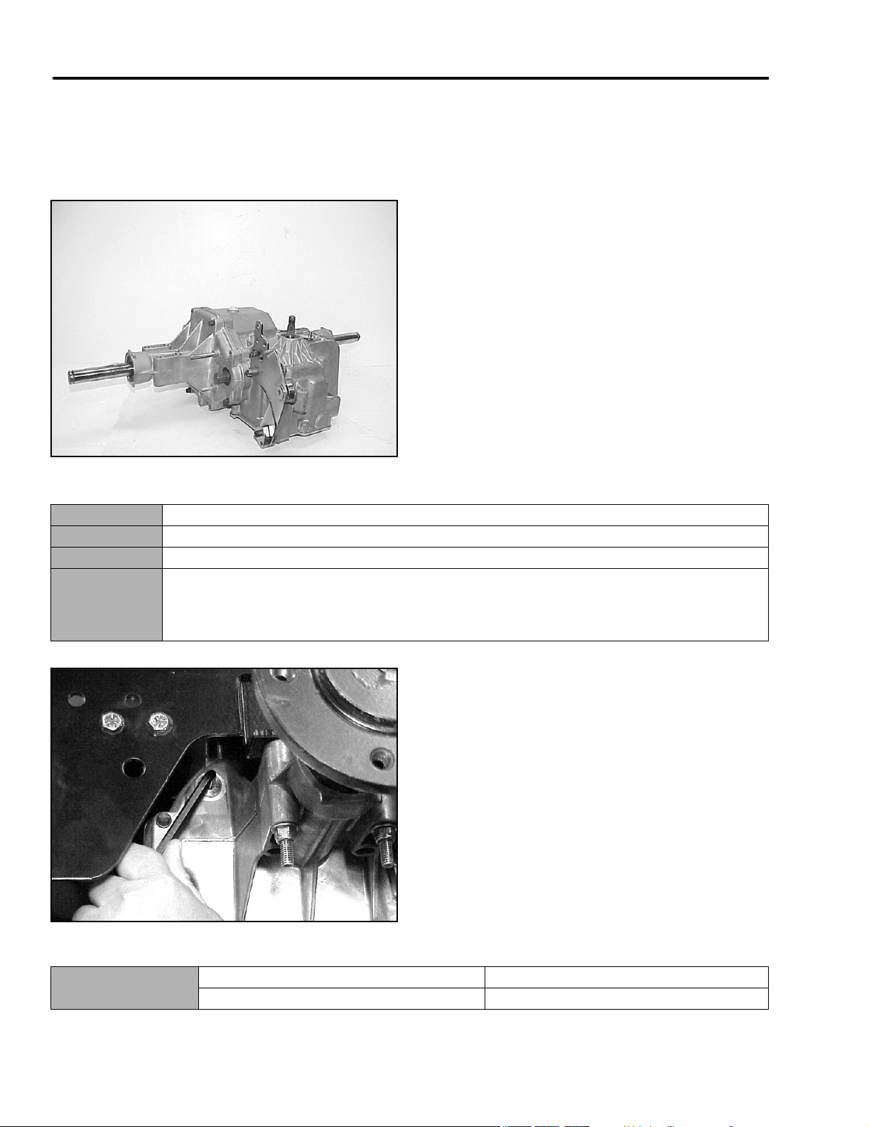
Hydrostatic Transaxles
Identification:
Hydro-Gear Model 322-3000 & 330-3000 Transaxle
MVC-082X
General Specifications
Used 2000 to 2002
Lubrication SAE 20W-50 API Classification SH/CD
Oil Capacity 3.8 qt. (3.6liters)
Oil Level The transaxle is a sealed system and does not require periodic checking. If the oil needs to be
checked, IT CAN ONLY BE CHECKED COLD. There is a plug located on the right rear side
of the transaxle. Using a ¼ inch Allen wrench, slowly remove the plug. Oil level should be to
the bottom of the port.
F9260-09
General Specifications
Ground Speed Forward 0 – 6.3 MPH (10.1km/h)
Reverse 0 – 2.3 MPH (3.7km/h)
1 - 4 260 Series Tractor Service Manual
Page 13
SPECIFICATIONS
Torque Specifications
Recommended fastener torque values are listed in the
following tables. For critical applications, as
determined by Toro, either the recommended torque or
a torque that is unique to the application is clearly
identified and specified in the service manual.
These torque specifications for the installation and
tightening of fasteners shall apply to all fasteners which
do not have a specific requirement identified in the
service manual. The following factors shall be
considered when applying torque: cleanliness of the
fastener, use of a thread sealant (Loctite), degree of
lubrication on the fastener, presence of a prevailing
torque feature, hardness of the surface underneath of
the fastener’s head, or similar condition which affects
the installation.
As noted in the following tables, torque values should
be reduced by 25% for lubricated fasteners to
achieve the similar stress as a dry fastener. Torque
values may also have to be reduced when the fastener
is threaded into aluminum or brass. The specific
torque value should be determined based on the
aluminum or brass material strength, fastener size,
length of thread engagement, etc.
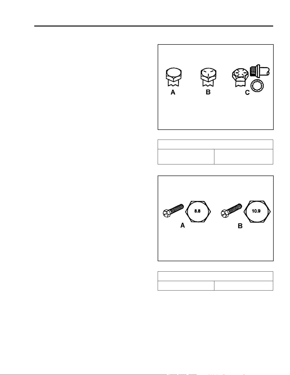
Fastener Identification
Inch Series Bolts and Screws
(A) Grade 1
(B) Grade 5
Figure 1
(C) Grade 8
The standard method of verifying torque shall be
performed by marking a line on the fastener (head or
nut) and mating part, then back off fastener 1/4 of a
turn. Measure the torque required to tighten the
fastener until the lines match up.
Figure 2
Metric Bolts and Screws
(A) Class 8.8 (B) Class 10.9
260 Series Tractor Service Manual 1 - 5
Page 14

SPECIFICATIONS
Standard Torque for Dry, Zinc Plated, and Steel Fasteners (Inch Series)
Grade 1, 5, &
Thread Size
# 6 - 32 UNC
# 6 - 40 UNF 17 ± 2 190 ± 20 25 ± 2 280 ± 20
# 8 - 32 UNC
# 8 - 36 UNF 31 ± 3 350 ± 30 43 ± 4 31 ± 3
# 10 - 24 UNC
#10 - 32 UNF 48 ± 4 540 ± 45 68 ± 6 765 ± 70
1/4 - 20 UNC 48 ± 7 53 ± 7 599 ± 79 100 ± 10 1125 ± 100 140 ± 15 1580 ± 170
1/4 - 28 UNF 53 ± 7 65 ± 10 734 ± 113 115 ± 10 1300 ± 100 160 ± 15 1800 ± 170
5/16 - 18 UNC 115 ± 15 105 ± 17 1186 ± 169 200 ± 25 2250 ± 280 300 ± 30 3390 ± 340
5/16 - 24 UNF 138 ± 17 128 ± 17 1446 ± 192 225 ± 25 2540 ± 280 325 ± 30 3670 ± 340
3/8 - 16 UNC 16 ± 2 16 ± 2 22 ± 3 30 ± 3 41 ± 4 43 ± 4 58 ± 5
3/8 - 24 UNF 17 ± 2 18 ± 2 24 ± 3 35 ± 3 47 ± 4 50 ± 4 68 ± 5
7/16 - 14 UNC 27 ± 3 27 ± 3 37 ± 4 50 ± 5 68 ± 7 70 ± 7 68 ± 9
7/16 - 20 UNF 29 ± 3 29 ± 3 39 ± 4 55 ± 5 75 ± 7 77 ± 7 104 ± 9
1/2 - 13 UNC 30 ± 3 48 ± 7 65 ± 9 75 ± 8 102 ± 11 105 ± 10 142 ± 14
1/2 - 20 UNF 32 ± 3 53 ± 7 72 ± 9 85 ± 8 115 ± 11 120 ± 10 163 ± 14
5/8 - 11 UNC 65 ± 10 88 ± 12 119 ± 16 150 ± 15 203 ± 20 210 ± 20 285 ± 27
5/8 - 18 UNF 75 ± 10 95 ± 15 129 ± 20 170 ± 15 230 ± 20 240 ± 20 325 ± 27
3/4 - 10 UNC 93 ± 12 140 ± 20 190 ± 27 265 ± 25 359 ± 34 374 ± 35 508 ± 47
3/4 - 16 UNF 115 ± 15 165 ± 25 224 ± 34 300 ± 25 407 ± 34 420 ± 35 569 ± 47
7/8 - 9 UNC 140 ± 20 225 ± 25 305 ± 34 430 ± 45 583 ± 61 600 ± 60 813 ± 81
7/8 - 14 UNF 155 ± 25 260 ± 30 353 ± 41 475 ± 45 644 ± 61 660 ± 60 895 ± 81
8 with Thin
Height Nuts
In-lb In-lb N-cm In-lb N-cm In-lb N-cm
10 ± 2 13 ± 2 147 ± 23
13 ± 2 25 ± 5 282 ± 30
18 ± 2 30 ± 5 339 ± 56
ft-lb ft-lb N-m ft-lb N-m ft-lb N-m
SAE Grade 1 Bolts, Screws,
Studs, & Sems with Regular
Height Nuts (SAE J995
Grade 2 or Stronger Nuts)
SAE Grade 5 Bolts, Screws,
Studs, & Sems with Regular
Height Nuts (SAE J995
Grade 2 or Stronger Nuts)
15 ± 2 170 ± 20 23 ± 2 260 ± 20
29 ± 3 330 ± 30 41 ± 4 460 ± 45
42 ± 4 475 ± 45 60 ± 6 674 ± 70
SAE Grade 8 Bolts, Screws,
Studs, & Sems with Regular
Height Nuts (SAE J995
Grade 2 or Stronger Nuts)
Note: Reduce torque values listed in the table above
by 25% for lubricated fasteners. Lubricated fasteners
are defined as threads coated with a lubricant such as
oil, graphite, or thread sealant such as Loctite.
Note: The nominal torque values listed above for
Grade 5 and 8 fasteners are based on 75% of the
minimum proof load specified in SAE J429. The
tolerance is approximately
value. Thin height nuts include jam nuts.
± 10% of the nominal torque
Note: Torque values may have to be reduced when
installing fasteners into threaded aluminum or brass.
The specific torque value should be determined based
on the fastener size, the aluminum or base material
strength, length of thread engagement, etc.
1 - 6 260 Series Tractor Service Manual
Page 15

SPECIFICATIONS
Standard Torque for Dry, Zinc, and Steel Fasteners (Metric Fasteners)
Class 8.8 Bolts, Screws, and Studs with
Thread Size
M5 X 0.8 57 ± 5 in-lb 640 ± 60 N-cm 78 ± 7 in-lb 885 ± 80 N-cm
M6 X 1.0 96 ± 9 in-lb 1018 ± 100 N-cm 133 ± 13 in-lb 1500 ± 150 N-cm
M8 X 1.25 19 ± 2 ft-lb 26 ± 3 N-m 27 ± 2 ft-lb 36 ± 3 N-m
M10 X 1.5 38 ± 4 ft-lb 52 ± 5 N-m 53 ± 5 ft-lb 72 ± 7 N-m
M12 X 1.75 66 ± 7 ft-lb 90 ± 10 N-m 92 ± 9 ft-lb 125 ± 12 N-m
M16 X 2.0 166 ± 15 ft-lb 225 ± 20 N-m 229 ± 22 ft-lb 310 ± 30 N-m
M20 X 2.5 325 ± 33 ft-lb 440 ± 45 N-m 450 ± 37 ft-lb 610 ± 50 N-m
Note: Reduce torque values listed in the table above
by 25% for lubricated fasteners. Lubricated fasteners
are defined as threads coated with a lubricant such as
oil, graphite, or thread sealant such as Loctite.
Note: Torque values may have to be reduced when
installing fasteners into threaded aluminum or brass.
The specific torque value should be determined based
on the fastener size, the aluminum or base material
strength, length of thread engagement, etc.
Regular Height Nuts
(Class 8 or Strong Nuts)
Note: The nominal torque values listed above are
based on 75% of the minimum proof load specified in
SAE J1199. The tolerance is approximately
the nominal torque value. Thin height nuts include jam nuts.
Class 10.9 Bolts, Screws, and Studs with
Regular Height Nuts (
Class 10 or Strong Nuts)
± 10% of
260 Series Tractor Service Manual 1 - 7
Page 16

SPECIFICATIONS
Other Torque Specifications
SAE Grade 8 Steel Set Screws
Recommended Torque
Thread Size
Square Head Hex Socket
1/4 - 20 UNC 140 ± 20 in-lb 73 ± 12 in-lb
5/16 - 18 UNC 215 ± 35 in-lb 145 ± 20 in-lb
3/8 - 16 UNC 35 ± 10 ft-lb 18 ± 3 ft-lb
1/2 - 13 UNC 75 ± 15 ft-lb 50 ± 10 ft-lb
Thread Cutting Screws
(Zinc Plated Steel)
Type 1, Type 23, or Type F
Thread Size Baseline Torque*
No. 6 - 32 UNC 20 ± 5 in-lb
Wheel Bolts and Lug Nuts
Thread Size Recommended Torque**
7/16 - 20 UNF
Grade 5
1/2 - 20 UNF
Grade 5
M12 X 1.25
Class 8.8
M12 X 1.5
Class 8.8
** For steel wheels and non-lubricated fasteners.
Thread
Size
No. 6 18 20 20 ± 5 in-lb
Threads per Inch
Typ e A Type B
65 ± 10 ft-lb 88 ± 14 N-m
80 ± 10 ft-lb 108 ± 14 N-m
80 ± 10 ft-lb 108 ± 14 N-m
80 ± 10 ft-lb 108 ± 14 N-m
Thread Cutting Screws
(Zinc Plated Steel)
Baseline Torque*
No. 8 - 32 UNC 30 ± 5 in-lb
No.10 - 24 UNC 38 ± 7 in-lb
1/4 - 20 UNC 85 ± 15 in-lb
5/16 - 18 UNC 110 ± 20 in-lb
3/8 - 16 UNC 200 ± 100 in-lb
Conversion Factors
in-lb X 11.2985 - N-cm
ft-lb X 1.3558 = N-m
No. 8 15 18 30 ± 5 in-lb
No. 10 12 16 38 ± 7 in-lb
No. 12 11 14 85 ± 15 in-lb
* Hole size, material strength, material thickness and
finish must be considered when determining specific
torque values. All torque values are based on nonlubricated fasteners.
N-cm X - 0.08851 = in-lb
N-cm X 0.73776 - ft-lb
1 - 8 260 Series Tractor Service Manual
Page 17

SPECIFICATIONS
Equivalents and Conversions
Decimal and Millimeter Equivalents
Fractions Decimals mm Fractions Decimals mm
1/64 0.015625 0.397 33/64 0.515625 13.097
1/32 0.03125 0.794 16/32 0.53125 13.484
3/64 0.046875 1.191 35/64 0.546875 13.891
1/16 0.0625 1.588 9/16 0.5625 14.288
5/64 0.078125 1.984 37/64 0.578125 14.684
3/32 0.9375 2.381 19/32 0.59375 15.081
1/8 0.1250 3.175 5/8 0.6250 15.875
9/64 0.140625 3.572 41/64 0.640625 16.272
5/32 0.15625 3.969 21/32 0.65625 16.669
11/64 0.171875 4.366 43/64 0.671875 17.066
3/16 0.1875 4.762 11/16 0.6875 17.462
13/64 0.203125 5.159 45/64 0.703125 17.859
7/32 0.21875 5.556 23/32 0.71875 18.256
15/64 0.234375 5.953 47/64 0.734375 18.653
1/4 0.2500 6.350 3/4 0.7500 19.050
17/64 0.265625 6.747 49/64 0.765625 19.447
9/32 0.28125 7.144 25/32 0.78125 19.844
19/64 0.296875 7.541 51/64 0.796875 20.241
5/16 0.3125 7.541 13/16 0.8125 20.638
21/64 0.328125 8.334 53/64 0.828125 21.034
11/32 0.34375 8.731 27/32 0.84375 21.431
23/64 0.359375 9.128 55/64 0.859375 21.828
3/8 0.3750 9.525 7/8 0.8750 22.225
25/64 0.390625 9.922 57/64 0.890625 22.622
13/32 0.40625 10.319 29/32 0.90625 23.019
27/64 0.421875 10.716 59/64 0.921875 23.416
7/16 0.4375 11.112 15/16 0.9375 23.812
29/64 0.453125 11.509 61/64 0.953125 24.209
15/32 0.46875 11.906 31/32 0.96875 24.606
31/64 0.484375 12.303 63/64 0.984375 25.003
1/2 0.5000 12.700 1 1.000 25.400
1 mm = 0.03937 in. 0.001 in. = 0.0254 mm
260 Series Tractor Service Manual 1 - 9
Page 18

SPECIFICATIONS
To Convert Into Multiply By
Miles
Yards
Linear
Measurement
Area
Volum e
Weight
Pressure
Feet
Feet
Inches
Inches
Inches
Square Miles
Square Feet
Square Inches
Acre
Cubic Yards
Cubic Feet
Cubic Inches
Tons (Short)
Pounds
Ounces (Abdp.)
Pounds/Sq. In. Kilopascal 6.895
U.S. to Metric Conversions
Kilometers
Meters
Meters
Centimeters
Meters
Centimeters
Millimeters
Square Kilometers
Square Meters
Square Centimeters
Hectare
Cubic Meters
Cubic Meters
Cubic Centimeters
Metric Tons
Kilograms
Grams
1.609
0.9144
0.3048
30.48
0.0254
2.54
25.4
2.59
0.0929
6.452
0.4047
0.7646
0.02832
16.39
0.9078
0.4536
28.3495
Work
Liquid Volume
Liquid Flos
Tempe r a ture
Foot-pounds
Foot-pounds
Inch-pounds
Quarts
Gallons
Gallons/Minute Liters/Minute 3.785
Fahrenheit Celsius 1. Subtract 32°
Newton-Meters
Kilogram-Meters
Kilogram-Centimeters
Liters
Liters
1.356
0.1383
1.152144
0.9463
3.785
2. Multiply by 5/9
1 - 10 260 Series Tractor Service Manual
Page 19
CHASSIS
Model and Serial Number Location
The model and serial number plate location is under
the seat (Figure 3).
Figure 3
MVC-084X
Greasing and Lubrication
3. One located on the front axle pivot area (1 total)
(Figure 4).
Figure 4
Hydrostatic model tractors have one grease fitting on
the forward/reverse pedal (Figure 5).
MVC-085X
The machine should be greased every 50 hours or
yearly, whichever occurs first. You should grease
more frequently when operating conditions are
extremely dusty or sandy.
Grease Type: General-purpose grease.
There are 5 grease fittings located in the front axle
area:
1. One located on the inside of each wheel hub (2
total).
2. One located on each end of the front axle for the
spindles (2 total).
Figure 5
MVC-088X
260 Series Tractor Service Manual 2 - 1
Page 20
CHASSIS
On the gear drive tractors, there is a grease fitting
located on both the clutch and brake pedal (Figure 6).
Figure 6
MVC-089X
Front Wheel Toe-in
If there is uneven tire wear, lawn scuffing, or hard
steering, toe-in may need to be adjusted. The front
toe-in measurement should be 1/8” to ¼” (3 to 6mm).
This should be checked every 100 hours or once a
year, whichever occurs first.
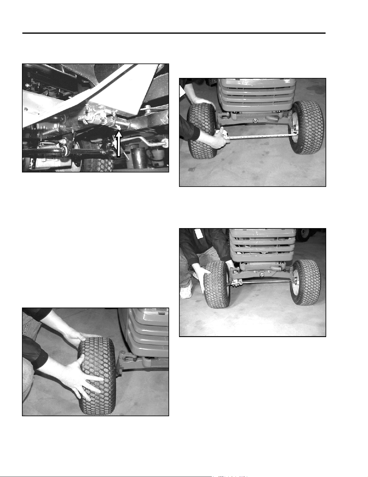
3. Measure the distance between both the front rims
at spindle level, in front and rear of the wheels.
You can also measure between the tread mold
marks if the tires are new (Figure 8).
Figure 8
4. The front measurement should be 1/8” to ¼” (3 to
6mm) less than the rear measurement (Figure 9).
If needed, follow the adjustment procedure.
MVC-092X
MEASUREMENT:
1. Disengage the PTO, set the parking brake, and
turn the ignition key to OFF to stop the engine.
Remove the key.
2. Push the front of the tires out to remove normal
looseness in the linkage (Figure 7).
Figure 7
MVC-091X
Figure 9
MVC-094X
2 - 2 260 Series Tractor Service Manual
Page 21
CHASSIS
Front Wheel Toe-in Adjustment
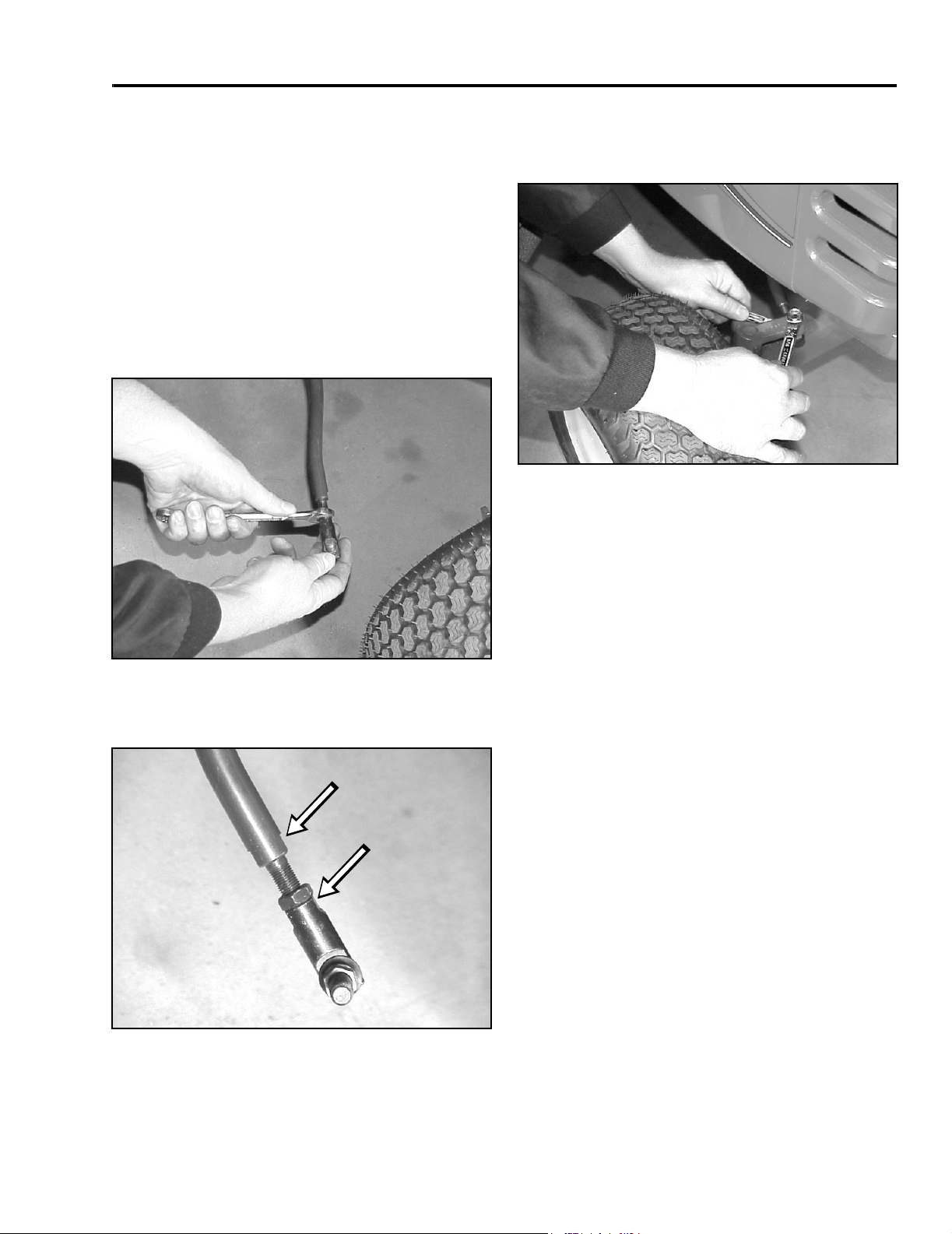
1. Remove the tie rod from one steering arm.
2. Loosen the jam nut securing the ball joint to the
steering rod. Rotate the ball joint one turn:
clockwise to increase toe-in; counterclockwise to
decrease toe-in (Figure 10).
IMPORTANT: If more than one turn is required
to meet specifications, alternate between the
right and left steering rods to maintain
steering wheel alignment.
4. Install the ball joint to the steering arm and check
the toe-in as described in the measurement
section (Figure 12).
Figure 12
MVC-099X
Front Wheel and Spindle Removal
and Installation
Figure 10
3. Hold flats on the ball joint to align with the flats on
the tie rod and tighten the jam nut (Figure 11).
Figure 11
MVC-095X
MVC-098X
Removal
1. Disengage the PTO. Set the parking brake, and
turn the ignition key to OFF to stop the engine.
Remove the key.
2. Raise the front axle by putting a jack under the
side you are removing the wheel or spindle from.
260 Series Tractor Service Manual 2 - 3
Page 22
CHASSIS
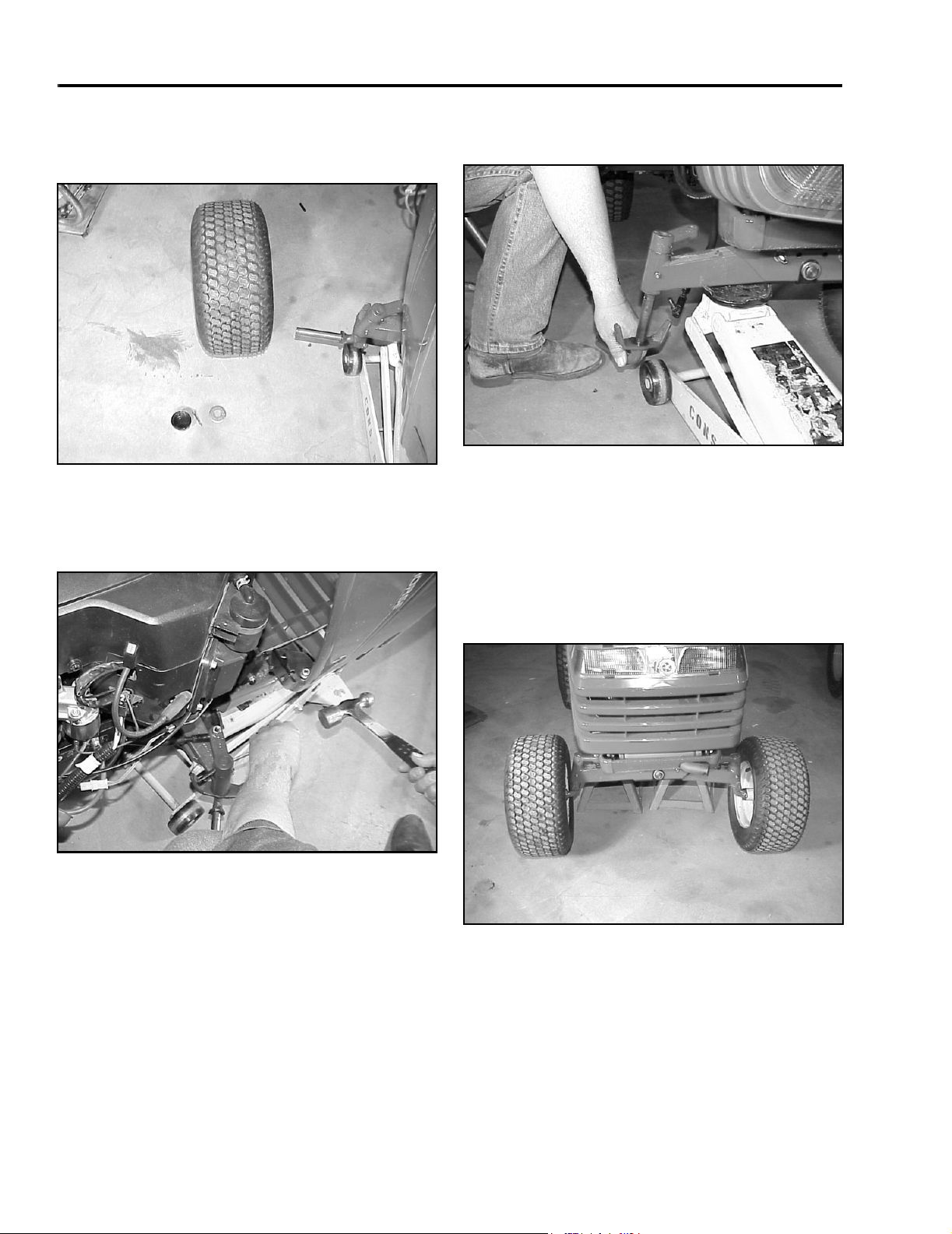
3. Remove the outer hub cap, cotter pin, washer,
and hub cap washer. Slide the wheel and tire off
the spindle (Figure 13).
Figure 13
4. Remove the tie rod from the front spindle arm.
With a drift punch and hammer, drive the roll pin
out of the front spindle arm (Figure 14).
MVC-100X
5. The spindle can now be removed out the bottom
of the front axle assembly (Figure 15).
Figure 15
6. Installation – reverse the order of removal.
MVC-102X
Front Axle Removal and Installation
Figure 14
MVC-101X
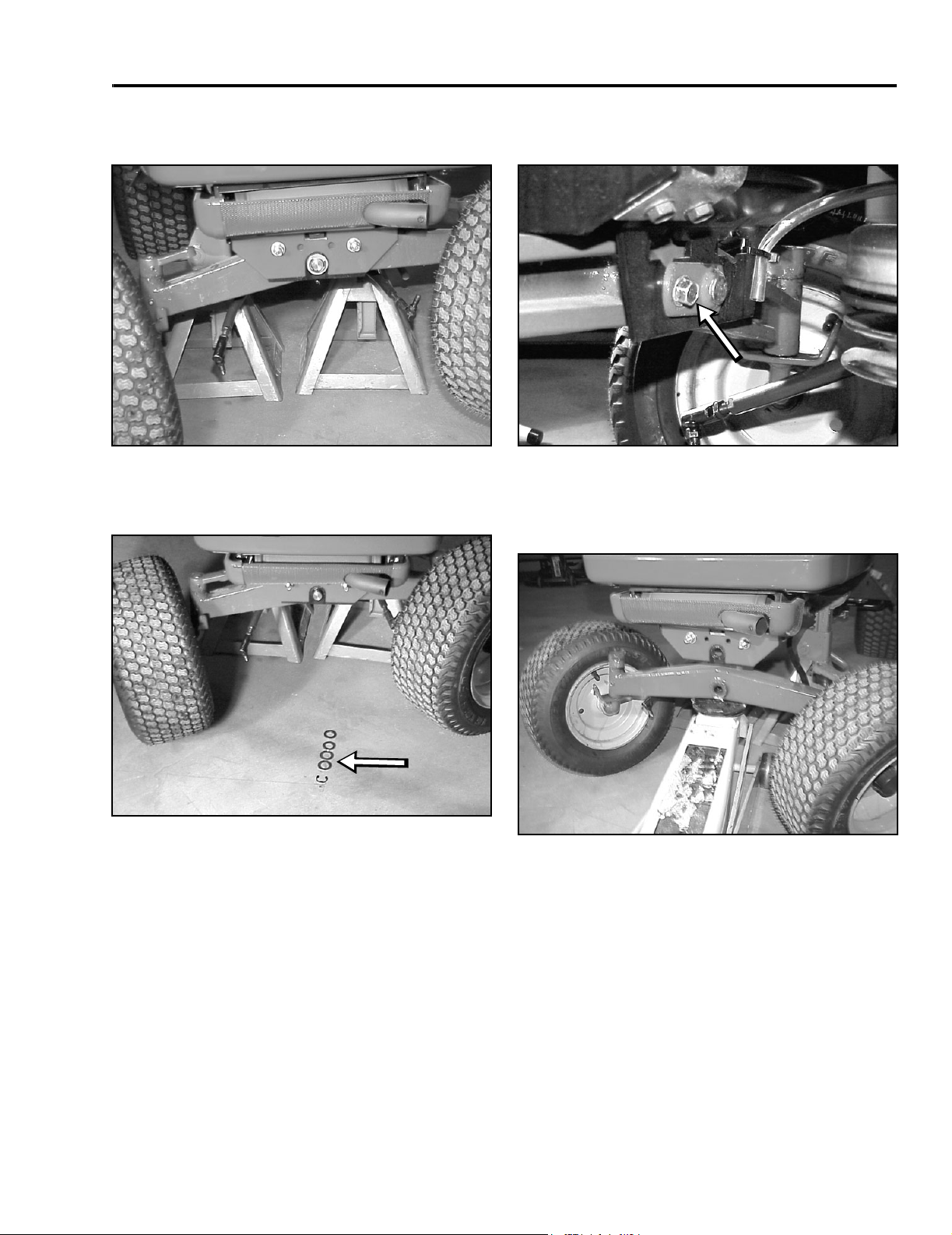
1. Jack-up the front of the tractor. Put jack stands
under the frame, just behind the front axle
assembly (Figure 16).
Figure 16
MVC-103X
2 - 4 260 Series Tractor Service Manual
Page 23
CHASSIS
2. Remove right and left tie rods from the front
spindle arms (Figure 17).
Figure 17
3. On the front of the axle, in the center, remove the
E-ring and washers (Figure 18).
MVC-105X
5. On the back side of the axle, remove the bolt on
the axle pin (Figure 19).
Figure 19
6. Remove the axle pin; use a drift punch and
hammer to tap the axle pin out; if needed (Figure
20).
MVC-107X
Figure 18
4. Remove the electric PTO clutch from the engine
crankshaft.
260 Series Tractor Service Manual 2 - 5
MVC-106X
Figure 20
7. Installation – reverse the order of removal.
MVC-108X
Page 24
CHASSIS
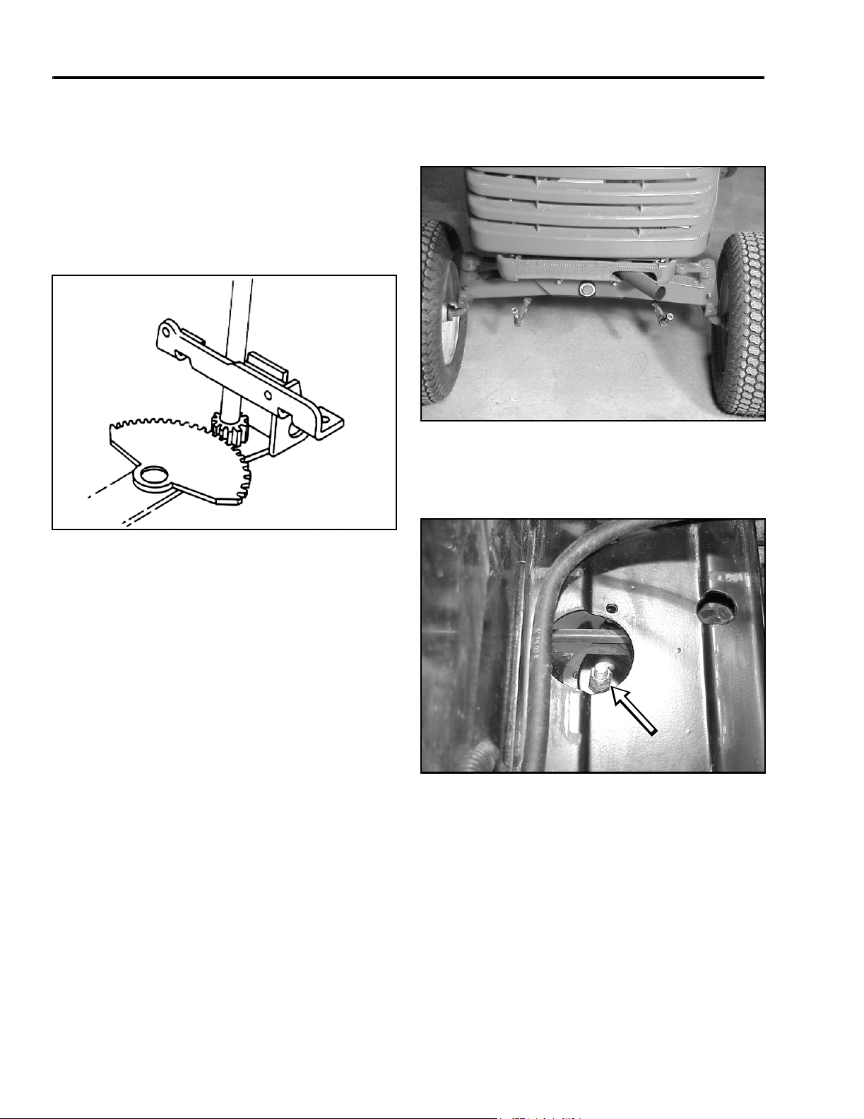
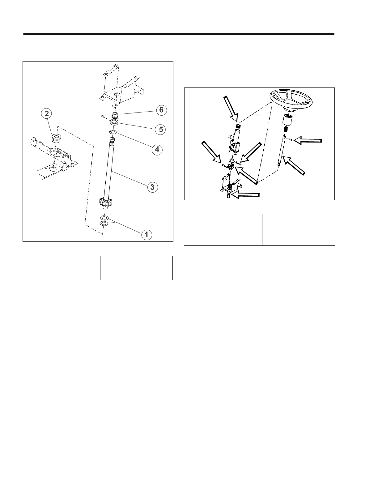
Steering Gear
Description
The steering gear assembly is made up of a vertically
mounted steering shaft and a horizontal sector gear.
The sector gear is adjustable so that excessive
backlash play in steering gears can be removed
(Figure 21).
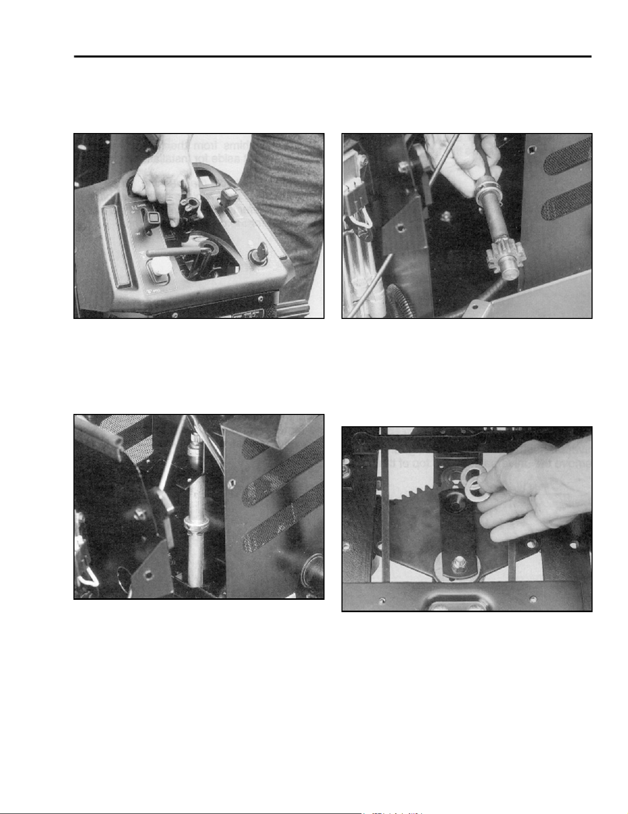
2. Position the steering wheel so the tie rods clear
the front axle and remove them from the steering
arms (Figure 22).
Figure 22
3. Loosen the locking nut on the eccentric (Figure
23). Position the steering wheel spokes so they
extend outward left to right.
MVC-263X
Figure 21
6-8
Steering Backlash Adjustment
Use the following procedure if there is excessive
steering backlash.
1. Remove battery and battery tray from the tractor.
Figure 23
MVC-110X
2 - 6 260 Series Tractor Service Manual
Page 25
CHASSIS
4. Tighten the nut until the eccentric turns with a
small amount of friction (Figure 21).
Figure 24
5. Using a punch, turn the eccentric clockwise until
zero clearance is obtained between the end of the
steering shaft gear and the steering sector (Figure
24).
MVC-113X
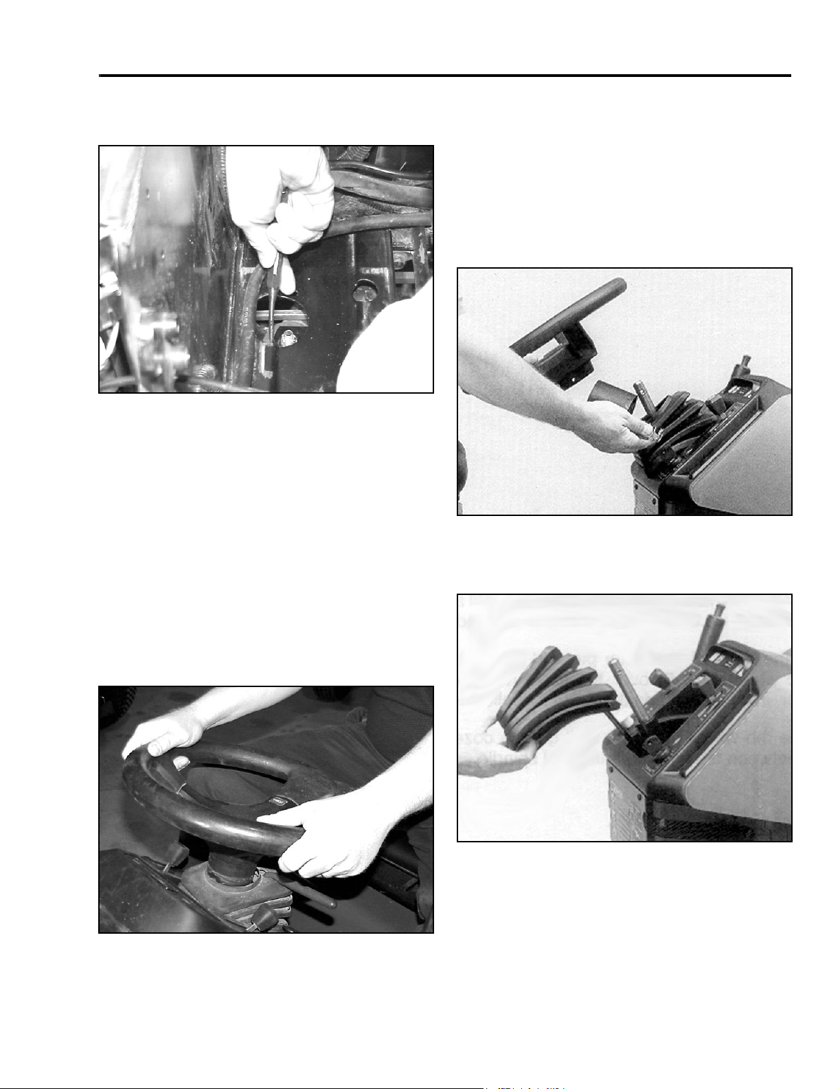
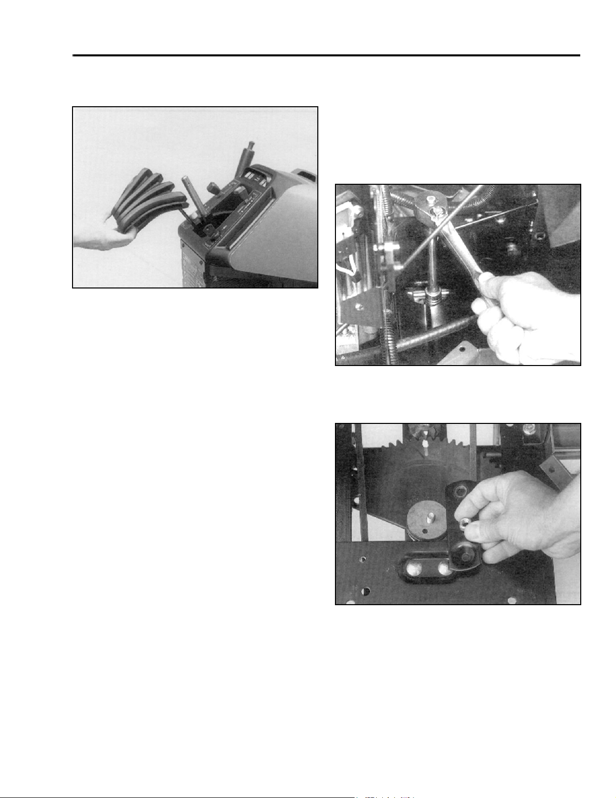
Steering Gear Shaft Disassembly
1. Disconnect the negative battery cable.
2. Remove the roll pin, steering wheel, spacer, and
spring from the top of the steering shaft (Figure
26). (Note: Some units use a retaining nut and
washer located under the center cover of the
steering wheel).
6. Tighten the nut to 25 – 35 ft lb (34 – 48 Nm). DO
NOT OVERTIGHTEN.
7. Apply some multipurpose grease to the steering
gear teeth.
8. Connect the tie rod ends to the steering arms.
9. Turn the wheels left and right. Recheck for zero
clearance (Figure 25).
Figure 26
3. Remove the rubber boot from the steering shaft
and console (Figure 27).
Figure 27
6-9
6-10
Figure 25
10. Reinstall the battery tray and battery.
260 Series Tractor Service Manual 2 - 7
MVC-115X
Page 26
CHASSIS
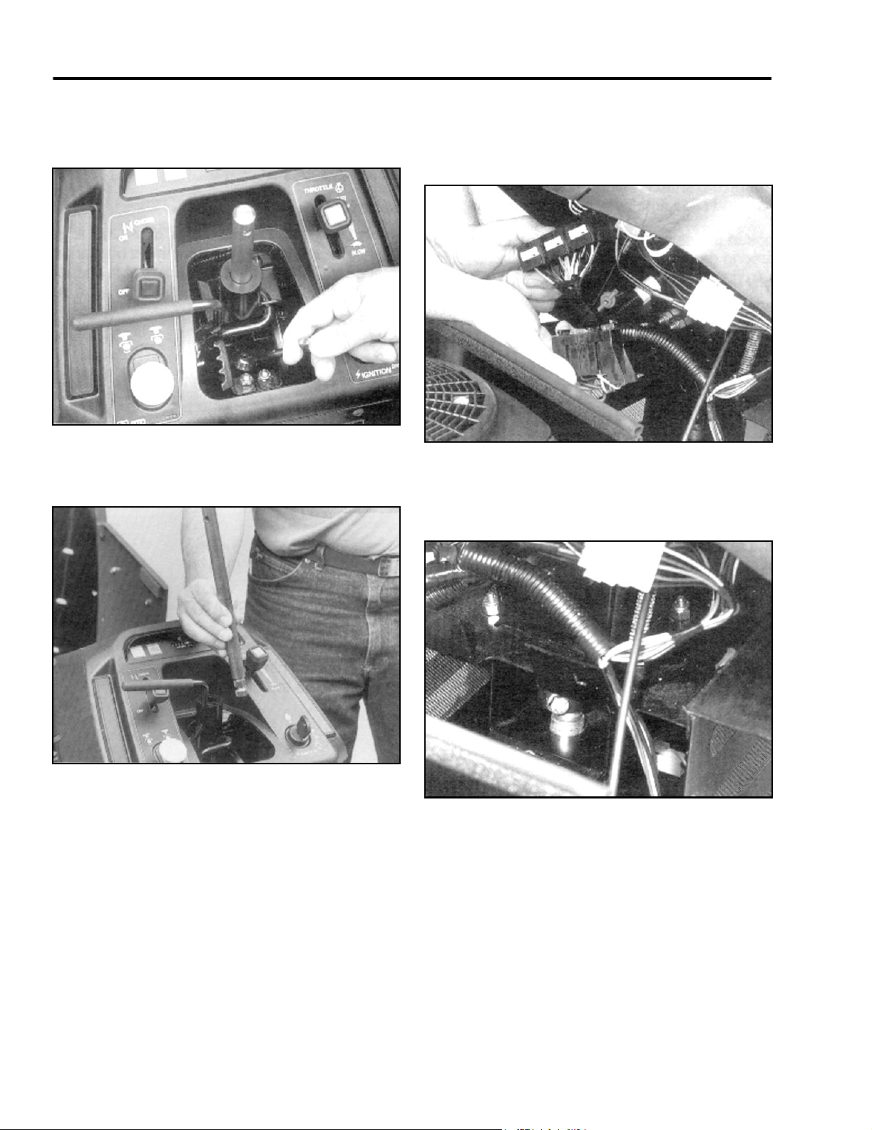
4. Rotate the steering shaft until the top bolt of the
universal joint faces the rear of the tractor.
Remove the bolt (Figure 28).
Figure 28
5. Pull the top shaft from the universal joint and
remove it from the top of the tractor (Figure 29).
6-11
6. Disconnect the relays from the mounting bracket
and remove the bracket from the tractor. Place
the wiring harness and fuse block to the side of
the console (Figure 30).
Figure 30
7. Rotate the steering gear shaft until the bottom bolt
of the universal joint faces the front of the tractor.
Remove the bolt (Figure 31).
6-13
Figure 29
2 - 8 260 Series Tractor Service Manual
6-12
Figure 31
6-14
Page 27
CHASSIS
8. Tilt steering to the rear position and remove the
universal joint from the steering shaft gear.
Remove the universal joint from the top of the
tractor (Figure 32).
Figure 32
9. Expand the snap ring found on the steering gear
shaft and slide if halfway down the shaft. Loosen
the setscrew on the locking collar of the steering
gear shaft and move it until it meets the snap ring
(Figure 33).
6-15
10. Lift the steering shaft upwards, out of the lower
bushing and through the opening in the mounting
bracket. Tilt the shaft towards the front of the
tractor and remove it (Figure 34).
Figure 34
11. Remove the shims from the top of the lower
bushing and set aside for installation process
(Figure 35). Important: Check the bushing,
shaft, and gears for wear and replace with new
parts if necessary. Refer to “Steering
Specifications” on page 2 - 15.
6-17
Figure 33
260 Series Tractor Service Manual 2 - 9
6-16
Figure 35
6-18
Page 28
CHASSIS
Steering Gear Assembly
Figure 36 6-19
5. Move the locking collar upward on the shaft until it
touches the column support mid bushing. Tighten
the collar set screw, then move the snap ring
upward on the shaft until it meets the bottom of
the locking collar (Figure 36).
6
3
3
4
5
1
2
Figure 37
(1) Universal Joint
(2) Lower Steering Gear
Shaft
(3) Retaining Bolts
(4) Roll Pin
(5) Upper Steering
Shaft
(6) Steering Bushing
6-22
(1) Shims
(2) Lower Bushing
(3) Steering Gear Shaft
1. Place two 0.05” (1.27mm) shims,1, between the
top of the bushing, 2, and the steering gear shaft,
3.
Note: Lubricate the bushing with never seize
lubricant during assembly.
2. Align the front wheels so that they face straight
ahead.
3. Install snap ring, 4; locking collar, 5; and upper
bushing, 6, onto the steering gear shaft.
4. Insert the steering gear shaft through the opening
in the mounting bracket and onto the lower
bushing.
Note: The shims must be in place.
(4) Snap Ring
(5) Locking Collar
(6) Mid Bushing
6. Tilt steering to the rear position and place the
universal joint,1, onto the top end of the lower
steering gear shaft, 2. Install the retaining bolt, 3,
of the universal joint through the joint and steering
gear shaft.
7. Place upper steering shaft, 5, onto the upper end
of the universal joint,1. Position the upper
steering shaft so that the roll pin hole runs
perpendicular (90°) to the tractor’s center line.
Install the retaining bolt, 3, through the upper end
of the universal joint and upper steering shaft.
Note: Ensure that electrical wiring can not come
into contact with upper steering shaft of universal
joint in any position.
2 - 10 260 Series Tractor Service Manual
Page 29
CHASSIS
8. Install the rubber boot over the steering shaft and
console (Figure 38).
Figure 38
9. Place the spring, spacer and steering wheel on
the steering shaft and install the roll pin. (Note:
Some steering wheels are secured with a
retaining nut and washer located under the center
cover of the steering wheel.) Install the relay
bracket, fuse block, battery tray, and battery.
Important: Ensure that all hardware is securely
fastened, that the steering wheel is centered when
the wheels are straight ahead, and that the
steering operates properly.
6-23
Sector Gear Disassembly
1. Remove the battery and plastic battery tray from
the tractor. Disconnect both steering tie rods from
the sector gear. Using the access hole in the
mounting bracket, remove the locknut and
carriage bolt holding the sector in place (Figure
39).
Figure 39
2. Remove the locking plate from the top of the
sector gear (Figure 40).
6-25
Note: Ensure that electrical wiring can not come
into contact with upper steering shaft of universal
joint in any position.
Figure 40
3. Remove the cam bushing, 3, from the sector gear.
Separate the sector gear, 2, from the mounting
bracket (Figure 41).
Important: Inspect the sector gear teeth and cam
bushing for wear and replace if necessary.
6-26
260 Series Tractor Service Manual 2 - 11
Page 30
CHASSIS
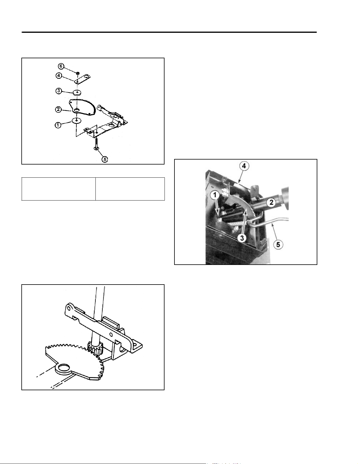
Sector Gear Assembly
Figure 41 6-28
(1) Washer Bearing
(2) Sector Gear
(3) Bushing
1. Install the bearing washer, 1, on the mounting
bracket (Figure 41).
(4) Locking Plate
(5) Carriage Bolt
(6) Locknut
5. Place the locking plate, 4, on the cam bushing
(Figure 41).
6. From the bottom, insert the carriage bolt, 5,
through the bearing washer, cam bushing, and the
locking plate. Secure the bolt with the locknut, 6
(Figure 41).
7. Adjust the steering gear, refer to “Steering
Backlash Adjustment” on page 2 - 6.
8. Fasten both steering arms onto the sector gear.
Check wheel alignment and toe-in.
Tilt Steering
2. Place the sector gear, 2, on top of the bearing
washer with the teeth facing the rear of the tractor
(Figure 41).
3. Center the steering shaft with the sector gear
(Figure 42). Make sure the steering wheel is
centered.
Figure 42
Figure 43 6-34
Description
The tilt steering assembly is made up of the following
components (Figure 43):
1. Universal joint.
2. Steering column (bushing mounted).
3. Detent bracket (left side).
4. Support bracket (right side).
5. Spring-loaded control handle.
6-8
4. Insert the cam bushing, 3, into the bore of the
sector gear (Figure 41).
2 - 12 260 Series Tractor Service Manual
Page 31

CHASSIS
(1) Retaining Bolt
(2) Universal Joint
(3) Retaining Bolt
(4) Upper Steering Shaft and Roll Pin
(Note: Some units have retaining nut and washer
located in the center steering wheel cover.)
Tilt Steering Disassembly
1. Remove the roll pin, steering wheel, spacer, and
spring from top of the steering shaft (Figure 45).
(Note: Some units use a retaining nut and washer
located under the center cover of the steering
wheel.)
Figure 44 6-35
(5) Spring Extension
(6) Bolts
(7) Nuts
(8) Detent Bracket
(9) Support Bracket
(10) Retaining Bolt
(11) Spacer-Yoke
(12) Column
(13) Tilt Lever
(14) Steering Bushing
Figure 45
260 Series Tractor Service Manual 2 - 13
6-9
Page 32

CHASSIS
2. Remove the rubber boot from the steering console
(Figure 46).
Figure 46
3. Remove the bottom retaining bolt, 1, from the
universal joint, 2 (Figure 44).
4. Remove the top retaining bolt, 3, from the
universal joint and disconnect the top steering
shaft, 4, from the tractor (Figure 44).
5. Tilt steering to the rear position and detach the
universal joint from the steering gear shaft. Take
the universal out of the tractor from the top side.
6-10
Tilt Steering Assembly
1. Place bushing, 14, on top of the steering column
(Figure 44).
2. Insert the tilt control handle, 13, into the steering
column bracket (Figure 44).
3. Secure the steering column to the mounting
bracket with pivot bolts, 10; spacers, 11; and
locknuts (Figure 44).
Note: The longer spacers should be positioned
on the left-hand side.
4. Install the left, 8, and right, 9, support brackets.
Fasten the notched bracket to the left side using
four bolts, 6, and nuts, 7. Adjust the brackets to
obtain minimal side play between the column and
brackets (Figure 44).
5. Attach the spring, 5, to the tilt handle and left pivot
spacers (Figure 44).
6. Tilt steering to its farthest rearward position and
place the universal joint, 2, on the steering gear
shaft. Pass the bottom bolt, 1, of the universal
joint through the universal and steering gear shaft
and secure (Figure 44).
6. Remove the spring, 5, from the left pivot spacer
and tilt control handle (Figure 44).
7. Remove the four bolts, 6, and nuts, 7, from the left
and right support brackets, 8, and 9, and remove
the brackets (Figure 44).
8. Remove the two side pivot bolts, 10, and spacers,
11, from the steering column. Lift the column, 12,
out of the tractor (Figure 44).
9. Slide the tilt control handle, 13, off the steering
column bracket (Figure 44).
10. Remove the bushing, 14, from the top of the
steering column (Figure 44).
Important: Inspect all bushings and pivot areas
for wear and replace as necessary. Refer to
“Steering Specifications” on page 2 - 15.
7. Insert the top steering shaft, 4, onto the upper end
of the universal joint. Check the front wheel
alignment, wheels should be straight ahead.
Position the steering shaft so that the roll pin hole,
(if the steering wheel is retained by a roll pin), runs
perpendicular (90º) to the tractor's center line.
Install the retaining bolt, 3, through the upper end
of the universal joint and steering shaft (Figure
44).
Note: Ensure electrical wiring can not come into
contact with upper steering shaft or universal joint
in any position.
2 - 14 260 Series Tractor Service Manual
Page 33

CHASSIS
8. Install the rubber boot over the steering shaft and
console (Figure 47).
Figure 47
6-10
Steering Specifications
9. Place the spring, spacer, and steering wheel on
the steering shaft. Secure the steering wheel with
a roll pin or with the washer and nut as applicable
(Figure 48).
Figure 48
6-9
Item Specification
Free Play – front axle pivot pin 0 – 0.015” (0 – 0.4mm)
End Play – wheel to spindle 0 – 0.015” (0 – 0.4mm)
Toe-In 1/8” – ¼” (3 – 6mm)
Steering Wheel Free Play 0.5” – 1.0” (13 – 25mm)
Steering Shaft Bushings (standard dimensions)
Top (Fiber) ID 0.752 – 0.756” (19.1 – 19.2mm)
OD 1.310 – 1.320” (33.3 – 33.5mm)
Mid (Metal) ID 0.755 – 0.760” (19.2 – 19.3mm)
OD 0.988 – 1.00” (25.3 – 25.4mm)
Bottom (Metal) ID 0.753 – 0.758” (19.1 – 19.2mm)
OD 1.380 – 1.385” (35.0 – 35.2mm)
260 Series Tractor Service Manual 2 - 15
Page 34

CHASSIS
Hood Removal
1. Disconnect the headlight wiring harness (Figure
49).
Figure 49
2. Remove the bolts and nuts located at the bottom
of the hood (Figure 50).
MVC-116X
Seat and Fender Removal
1. Unplug the seat switch, and if equipped with
KeyChoice™ Reverse operating system, unplug
the KeyChoice™ switch (Figure 51).
Figure 51
2. To make it easier to remove the fasteners for the
fender assembly, jack the tractor up in the rear
and remove both rear tires.
MVC-121X
Figure 50
3. Reinstall the hood in reverse order.
MVC-118X
3. Remove the two rear carriage bolts, washers, and
nuts located in the rear of the fender assembly
(Figure 52).
Figure 52
MVC-122X
2 - 16 260 Series Tractor Service Manual
Page 35

CHASSIS
4. Remove the four carriage bolts, washers, and
nuts, (two on the right and two on the left), that are
located between the footrest and fender (Figure
53).
Figure 53
5. Remove the seat and fender together as one
piece (Figure 54).
MVC-124X
2. Remove the two screws and spacers in the front
of the gas tank (Figure 55).
Figure 55
3. Lift the gas tank from the frame, close the gas
shut-off valve, and disconnect the gas line from
the shut-off valve (Figure 56).
MVC-129X
Figure 54
6. Installation - follow the removal procedure in
reverse.
MVC-126X
Figure 56
4. Carefully remove the gas tank.
5. Installation - reverse the order of removal.
MVC-130X
Gas Tank Removal
1. Follow the procedure for removing the rear fender
and seat.
260 Series Tractor Service Manual 2 - 17
Page 36

CHASSIS
Lift Lever Linkage
Figure 57 7-1
(A) Lift Lever
(B) Lift Arm Cross-Shaft
(C) Mounting Bracket
(D) Control Arm
(E) Handle Grip
The main components of the lift lever weldment are
the:
•Lift Lever, A
• Lift Arm Cross-Shaft, B
• Mounting Brackets, C and H
• Control Arm, D
2 - 18 260 Series Tractor Service Manual
(F) Tip Rod Button
(G) Lift Lever Rod
(H) Pivot Linkage Bracket
(I) Lift Rod
The mounting brackets, C and H, secure the lift
weldment to the tractor frame and hold the lift arm
cross shaft, B, in place.
Handle Grip, E; spring-loaded button, F; and rod, G, is
released from its latching socket. This allows the lift
lever to rotate with the lift lever cross-shaft.
When the lift lever is returned to the latched position,
the spring tension pulls rod, G, back into the latching
socket, and the mower deck is secured in the raised
position.
Page 37

Dial-A-Height Linkage
CHASSIS
Figure 58 7-2
(J) Knob
(K) Trunnion
(L) Plate-HOC Gauge Bracket
(M) Rod-HOC Indicator Rod
(N) Lift Lever Weldment
The Dial-A-Height knob, J, is threaded through a
trunnion, K. A bracket, L, is attached to the trunnion
and the spring-loaded Dial-A-Height indicator rod, M.
The trunnion is also connected to the lift lever
weldment at point N.
As the Dial-A-Height knob, J, is adjusted through the
trunnion, K, the trunnion rotates the bracket, L. This
moves the Dial-A-Height rod, M.
260 Series Tractor Service Manual 2 - 19
Note: The Dial-A-Height rod is visible through the
center access plate between the fender and the hood
console.
At the same time, the trunnion rotates the cross shaft at
point, N, on the lift lever weldment, controlling the
distance the linkage will lower.
Page 38

CHASSIS
Lift Arm Linkage
Figure 59 7-3
(A) Rod
(B) Rear Lift Arm Assembly
(C) Front Lift Arm Assembly
The lift arm linkage is responsible for raising and
lowering the attachment and is made up of the
following main components:
•Lift rod
• Rear lift arm assembly
• Front lift arm assembly
• Leveling rod
• Cross shaft
• Gauge wheel lift link
• Mounting brackets
The lift rod, A, is connected to the lift lever weldment
and the rear lift arm assembly, B. The rear lift arm
assembly is attached to the front lift arm assembly, C,
by a leveling rod, D. It is also bolted to rear frame
hangers at the mounting brackets, F.
(D) Leveling Rod
(E) Cross Shaft
(F) Mounting Brackets
The front lift arm assembly, C, is secured to the tractor
by a cross shaft, E, which is mounted to the bottom of
the footrests. The mower gauge wheel lift link is
connected to the rear lift arm assembly at point G.
When the lift lever is moved, the lift rod, A, rotates the
rear lift arms, B, through the mounting brackets, F. The
gauge wheel lift link (connected to the rear lift arm
assembly at point G) raises and lowers with the lift
arms.
The front lift arms, C, rotate on the cross shaft, E.
Because the front lift arms are connected to the rear lift
arm assembly by a leveling rod, D. They also raise
and lower with the rear lift arms.
2 - 20 260 Series Tractor Service Manual
Page 39

CHASSIS
Adjustments
Lift Height
To obtain a positive latch when the lift handle is in the
full raised position, turn the ¾” nut on the lift rod, A, to
increase or decrease movement of the lift arm
assemblies, B and C.
Leveling
To position the two front lift arms parallel to the tractor
frame, disconnect the leveling rod, D, from the front lift
arms and turn the rod through the trunnion to alter its
length. This rotates the front lift arm assembly, C, on
the cross shaft, E.
Side to Side
When required, perform a side to side adjustment of
the rear lift arms by loosening and repositioning the
9/16” bolts found in the slots of the mounting brackets,
F.
Power Lifts
Electrohydraulic Lift (2000 and Prior Models)
Electric Lift (2001 and Later Models)
Figure 61 Electlift
(1) Actuator Bracket Assy.
(2) Clevis Pin
(3) E-Ring
(4) Pivot Bracket Linkage
(5) Flange Bearing
(6) Actuator
(7) Flat Washer
(8) Spacer
(9) Clevis Pin
(10) Lift Arm Assembly
(11) Flat Washer
(12) Battery Bracket
(13) Screw
Figure 60
For information on removal and repair of the
Electrohydraulic Lift, refer to Electrohydraulic Lift
Service Manual, Form Number 492-0704.
MVC-470X
Removal
1. Remove the hoodstand side panels to the battery
compartment.
2. Disconnect the negative and positive cables from
the battery.
3. Remove the screws, 13, from the battery bracket,
12, and remove the battery bracket.
4. Unplug the actuator, 6, from the wiring harness.
5. Remove the e-ring, 3, from the end of the clevis
pin, 9.
6. Remove the clevis pin, 9, washers, 7, and
spacers, 8.
7. Remove e-ring, 3, and remove clevis pin, 2.
8. Remove the actuator
Installation
Reverse the order of removal.
260 Series Tractor Service Manual 2 - 21
Page 40

THIS PAGE INTENTIONALLY LEFT BLANK
2 - 22 260 Series Tractor Service Manual
Page 41

TUFF TORQ TRANSAXLE
Tuff Torq Hydrostatic Transaxle
Internal Service
Internal service information is contained in the Tuff
Torq KGIA Transaxle Service Manual, Form 492-0699.
Fluid Change
The Tuff Torq transaxle is factory filled, sealed, and
does not require oil changes. However, in the event of
oil contamination or degradation, oil replacement may
correct certain performance problems. Refer to the
Transaxle Service Manual.
Transaxle Removal – Tuff Torq
1. Disconnect the negative battery cable from the
battery.
2. Raise the rear of the tractor and remove the right
and left rear tires. Support the rear frame, just in
front of the transaxle. Remove the fender, seat,
and gas tank. (Refer to the “Chassis” section on
page 2 - 16.) Remove the center access plate
between the fender and hoodstand (Figure 62).
3. Disconnect the cotter pin and the washer to the
brake rod (Figure 63).
Figure 63
4. Disconnect the cotter pin for the free wheeling
valve rod (Figure 64).
MVC-322X
Figure 64
Figure 62
260 Series Tractor Service Manual 3 - 1
MVC-321X
MVC-323X
Page 42

TUFF TORQ TRANSAXLE
5. Loosen the hose clamp around the reservoir hose
and remove from the top of the transaxle. Clean
the area from around the hose before removing
(Figure 65).
Figure 65
6. Unbolt the forward/reverse control rod. Note: This
tractor has cruise control and the forward/reverse
control rod is disconnected from the cruise plate
which is bolted to the control shaft assembly
(Figure 66).
MVC-324X
7. If the tractor is equipped with cruise control,
disconnect the plug and jack for the cruise control
magnet. Unbolt the cruise control magnet bracket
(Figure 67).
Figure 67
8. Unhook the idler spring at the bolt and spacer
located on the right side of the frame (Figure 68).
MVC-326X
Figure 68
Figure 66
3 - 2 260 Series Tractor Service Manual
MVC-325X
MVC-327X
Page 43

TUFF TORQ TRANSAXLE
9. Remove the 3 screws retaining the transaxle fan
to the input pulley; this will give you enough
clearance to remove the drive belt from the
transaxle input pulley (Figure 69).
Figure 69
10. Use a floor jack and put it under the transaxle to
help lower the transaxle from the frame (Figure
70).
MVC-328X
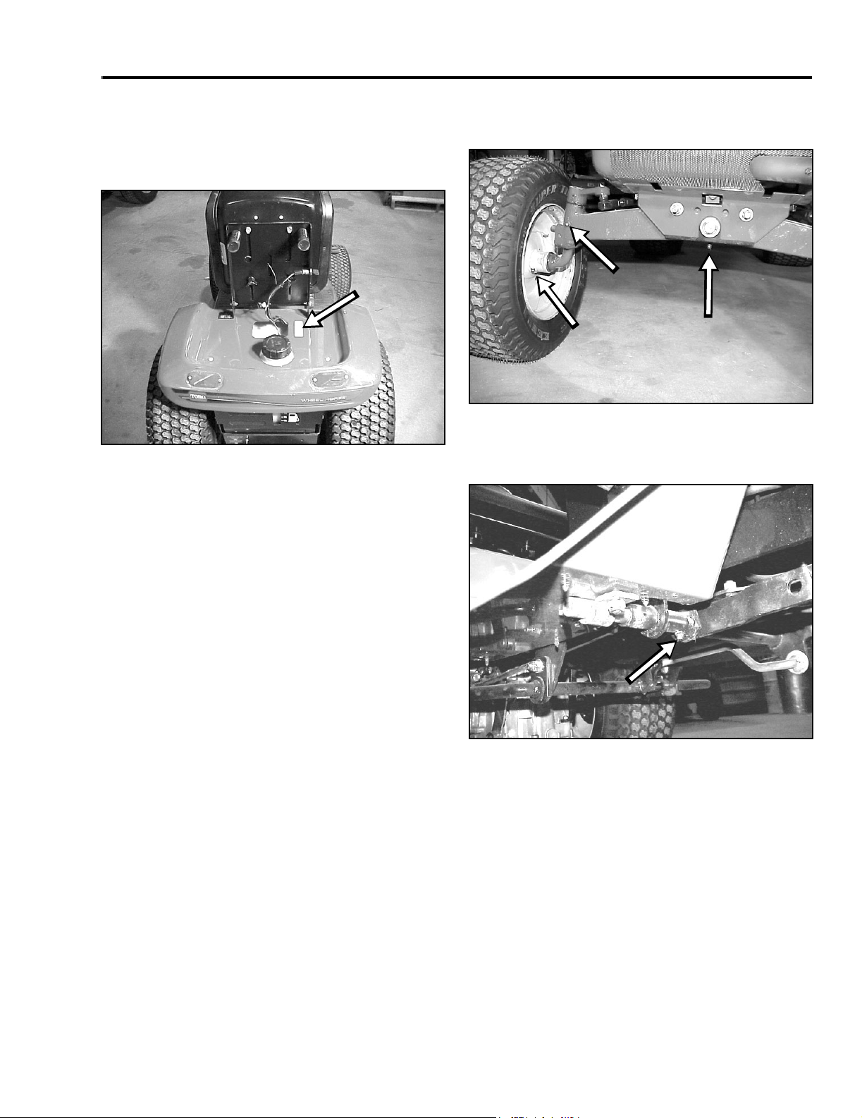
11. Located on the right front side of the transaxle is a
torque strap. Remove the bolt and nut (Figure
71).
Figure 71
12. Remove the 4 nuts from the U-bolts which hold
the two axle shafts to the frame (Figure 72).
MVC-330X
Figure 72
Figure 70
260 Series Tractor Service Manual 3 - 3
MVC-329X
lMVC-331X
Page 44

TUFF TORQ TRANSAXLE
13. Slowly lower the transaxle out of the frame (Figure
73).
Figure 73
MVC-333X
Installation - Tuff Torq Transaxle
1. Raise the transaxle up toward the frame (Figure
74).
2. Install the 4 washers and nuts to the U-bolts
retaining the two axle shafts to the frame and
tighten (Figure 75).
Figure 75
3. Install the bolt, washer, and nut for the torque
strap and tighten (Figure 76).
MVC-331X
Figure 76
Figure 74
3 - 4 260 Series Tractor Service Manual
MVC-334X
MVC-330X
Page 45

TUFF TORQ TRANSAXLE
4. Bolt the forward/reverse control rod to the control
shaft assembly (Figure 77).
Figure 77
5. Before installing the brake rod trunnion into the
brake control lever, make sure the brake control
lever is in its most rearward position and hold it
there. Adjust the trunnion on the brake rod until it
slips into the brake control lever. Secure with
washer and cotter pin (Figure 78).
MVC-325X
6. Attach the freewheeling rod to the lever with a
cotter pin (Figure 79).
Figure 79
7. Install the hose clamp and the reservoir hose to
the top of the transaxle. Add oil to the reservoir
cup located under the front hood to the cold mark,
located on the side of the cup (Figure 80).
MVC-323X
Figure 80
Figure 78
260 Series Tractor Service Manual 3 - 5
MVC-322X
MVC-337X
Page 46

TUFF TORQ TRANSAXLE
8. Install the drive belt around the transaxle pulley
and also install the transaxle cooling fan with the 3
retaining screws (Figure 81).
Figure 81
9. If the tractor has cruise control, reinstall the cruise
control magnet bracket and reconnect the plug
and jack wiring. Use a tie wrap to tie the wire to
the transaxle damper (Figure 82).
MVC-338X
10. Check the belt routing through the idler pulleys
and hook the idler spring at the bolt and spacer
located on the right side of the frame (Figure 83).
Figure 83
11. Purging of the transaxle is needed to remove
trapped air after repairs. Follow the “Purging
Procedures – Tuff Torq Transaxle” on page 3 - 15.
12. Check the neutral adjustment. If the unit needs to
be neutralized, follow the procedures, “Neutral
Adjustment – Tuff Torq Transaxle” on page 3 - 17).
MVC-327X
Figure 82
MVC-341X
13. Reconnect the battery negative cable and test
operate the tractor, making sure the safety circuits
and the tractor are operating properly.
14. Recheck the transaxle oil reservoir level; top off if
needed.
Belt Replacement – Tuff Torq
Transaxle
Note: Perform belt installation, routing, and inspection
procedures from beneath the tractor.
3 - 6 260 Series Tractor Service Manual
Page 47

TUFF TORQ TRANSAXLE
1. Disconnect the negative battery cable.
Disconnect the electric PTO clutch wire. There is
a tie strap through the frame of the tractor around
the clutch wire that needs to be cut to release the
clutch wire. Also, remove the battery drain tube
from the tie strap (Figure 84).
Figure 84
2. Remove the two steering tie rods from the
steering sector gear (Figure 85).
MVC-342X
4. Unhook the idler spring at the bolt and spacer
located on the right side of the frame (Figure 86).
Figure 86
5. Remove the cotter pin and washer on the brake
rod at the transaxle (Figure 87).
MVC-327X
3. Remove the fender, seat, and gas tank (refer to
the “Chassis” section on page 2 - 16
Figure 85
MVC-343X
Figure 87
MVC-322X
260 Series Tractor Service Manual 3 - 7
Page 48

TUFF TORQ TRANSAXLE
6. Remove the 3 screws retaining the transaxle fan
to the input pulley (Figure 88).
Figure 88
7. Unbolt the hydrostatic control rod from the
forward/reverse control pedal (Figure 89).
MVC-344X
8. Remove the 2 bolts holding the safety neutral
switch bracket (Figure 90).
Figure 90
9. Remove the 2 carriage bolts holding the righthand footrest to the frame (Figure 91).
MVC-346X
Figure 89
3 - 8 260 Series Tractor Service Manual
MVC-345X
Figure 91
MVC-350X
Page 49

TUFF TORQ TRANSAXLE
10. Loosen the left pedal pivot shaft clamp. Remove
the right pedal pivot shaft clamp (Figure 92).
Figure 92
11. Unhook the brake rod return spring, located under
the center access plate (Figure 93).
MVC-351X
12. Remove the roll pin holding the brake cross shaft
and slide the shaft out to clear the bushing (Figure
94).
Figure 94
13. Install the belt around and above the electric
clutch. Feed the belt above the steering sector
gear and over the brake shaft and pedal pivot
shaft (Figure 95).
MVC-353X
Figure 93
MVC-352X
C
(A) Brake Shaft
(B) Pedal Pivot Shaft
Figure 95
A
B
MVC-354X
(C) Steering Sector
Gear
260 Series Tractor Service Manual 3 - 9
Page 50

TUFF TORQ TRANSAXLE
Belt Routing
Figure 96
14. Install the belt around the transaxle input pulley
and then around the idler pulley assembly. Install
the id l er sp ri ng t o t he bo lt , spa c er, and was he r
located on the right side of the frame (Figure 97).
Beltroute
15. Slide the brake shaft back through the bushing
and install the roll pin. Raise the pedal pivot shaft
up to the footrest and install and tighten the
clamps (Figure 98).
Figure 98
16. Install the 2 bolts in the safety neutral bracket and
tighten the bolts (Figure 99).
MVC-357X
Figure 97
3 - 10 260 Series Tractor Service Manual
MVC-356X
Figure 99
MVC-346X
Page 51

TUFF TORQ TRANSAXLE
17. Reattach the brake rod return spring, located
under the center access plate (Figure 100).
Figure 100
18. Bolt the hydrostatic control rod to the forward/
reverse control pedal.
NOTE: Before tightening the bolt, check the pedal
adjustment (Figure 101). Refer to “Foot Control
Adjustment Procedure” on page 3 - 16.
MVC-352X
20. Reroute the PTO clutch wire through the frame
and tie strap the wire to the frame. Connect the
PTO clutch wire back into the plug. Install the
battery drain tube in the tie strap (Figure 102).
Figure 102
21. Reconnect the steering tie rods to the steering
sector gear (Figure 103).
MVC-361X
Figure 103
Figure 101
19. Check the belt tension. If adjustment is needed,
refer to “Belt Adjustment” on page 3 - 13.
260 Series Tractor Service Manual 3 - 11
MVC-345X
MVC-362X
Page 52

TUFF TORQ TRANSAXLE
22. Connect the brake rod to the brake lever on the
transaxle using a washer and cotter pin (Figure
104).
Figure 104
23. Install the fan on the transaxle input pulley (Figure
105).
MVC-322X
24. Check the routing of the drive belt (Figure 106 and
Figure 107).
Figure 106
Rear underside of tractor
MVC-368X
Figure 105
3 - 12 260 Series Tractor Service Manual
MVC-364X
Front underside of tractor
25. Reconnect battery negative cable. Reinstall
fender, seat, and gas tank.
26. Test the tractor, making sure all the safety devices
operate properly.
Figure 107 MVC-367X
Page 53

Belt Adjustment
TUFF TORQ TRANSAXLE
Figure 108
(A) Back Side Idler Pulley
(B) Idler Arm
(C) Eccentric
(D) Eccentric Mounted Idler Pulley
Remove the tunnel cover to check or adjust the belt tension. Loosen the back side idler pulley, A, and move it in
the slotted mounting hole on the idler arm, B. For additional adjustment, turn the eccentric C, on the eccentric
mounted idler pulley, D.
beltadjustment
260 Series Tractor Service Manual 3 - 13
Page 54

TUFF TORQ TRANSAXLE
Troubleshooting – Tuff Torq Transaxle
Problem Possible Cause
No Drive • Incorrect oil/oil level in unit.
• Drive belt has failed, is worn, or is out of adjustment.
• Push valve in push position.
• Parking brake engaged.
• Control pedal linkage worn, loose disconnected.
• Engine pulley or transmission pulley sheared/missing.
• Wheel hub key sheared/missing.
• Push valve stuck or spring broken.
• Damage to rotating groups or internal valving.
• Damaged pinion shaft or differential assembly.
No Drive – one direction • Control pedal bent or broken.
• Control pedal rod bent or binding.
• Control arm roll pin sheared.
• Directional valves sticking, broken springs, or need to be cleaned of debris.
Low Power – both directions • Incorrect oil/oil level in unit.
• Drive belt has failed, is worn, is out of position, at incorrect tension, or
engine. RPM is low.
• Push valve partially activated.
• Parking brake engaged or binding.
• Control pedal or linkage binding.
• Engine or transaxle drive pulleys loose, damaged, or worn.
• Directional valves sticking, need to be cleaned of debris, broken springs.
• Damage to rotating groups or valve body.
• Swash plate worn, damaged, not operating properly.
• Damaged output pinion or differential assembly.
Low Power – one direction • Incorrect oil/oil level in unit.
• Control pedal or shaft bent, binding, or travel.
• Control rod bent or binding.
• Control arm is not secure on shaft.
• Swash plate worn, damaged, not operating properly.
• Damaged output pinion or differential assembly.
Creeps in neutral • Neutral adjustment eccentric out of position.
• Control pedal bent or binding.
• Swash plate control lever pin damaged, bent, binding, or worn.
• Swash plate cradle bearings failed, worn, or damaged.
• Swash plate control arm ball and socket damaged or worn.
• Neutral return spring failed, fatigued, or out of position.
Refer to K61A Transaxle Service Manual, form # 492-0699, for internal service procedures.
3 - 14 260 Series Tractor Service Manual
Page 55

TUFF TORQ TRANSAXLE
Purging Procedures – Tuff Torq
Transaxle
Due to the effects air has on efficiency in hydrostatic
drive applications, it is critical that it be purged from the
system.
These purge procedures should be implemented any
time a hydrostatic system has been opened to facilitate
maintenance or any additional oil has been added to
the system.
Air creates inefficiency because its compression and
expansion rate is higher than that of the oil normally
approved for use in hydrostatic drive systems. The
resulting symptoms in hydrostatic systems may be:
1. Noisy operation.
2. Lack of power or drive after short term operation.
3. High operation temperature and excessive
expansion of “oil”. In the latter case, oil may
overflow.
Before starting, make sure the transaxle is at the "cold"
oil level; refer to “General Specifications” on page 1 - 3.
Top off as needed during the process.
7. Depress the forward hydrostatic control pedal and
push the tractor rearward. Then depress the
reverse hydrostatic control pedal and push the
tractor forward until the tractor is able to move
under its own power.
8. Increase engine speed to full RPM.
9. Operate the tractor from seated position, making
quick starts and panic stops, until the transaxle is
operating properly. Top forward speed is 5.2
MPH (8.3km/hr).
10. Top off the reservoir with oil through the reservoir/
fill cap, filling it to the cold fill mark.
Brake – Tuff Torq Transaxle
Always set the parking brake when you stop the
machine or leave it unattended. If the parking brake
does not hold securely, an adjustment is required.
Checking the Brake
1. Park the machine on a level surface, disengage
the power take off (PTO), set the parking brake,
and turn the ignition key to “OFF” to stop the
engine. Remove the ignition key.
1. Raise the two rear tires from the ground and
support the tractor securely with jack stands.
2. Disconnect the seat switch and attach a jumper
wire across the terminals so that the tractor will
run without an operator in the seat.
3. Start the engine and maintain low idle speed.
4. Depress the forward and reverse hydrostatic
control pedals alternately until the wheels begin to
rotate. Shut the engine off.
5. Lower the tractor to the ground.
Use extreme caution while completing the
following purging process.
6. Restart the engine and set at low idle speed.
2. Rear wheels must lock and skid when you try and
push the tractor forward. Adjustment is required if
the wheels turn and do not lock; refer to “Adjusting
the Brake – Tuff Torq Transaxle” on page 3 - 15.
3. Release the brake and move the drive control rod
to the “PUSH” position. Wheels should rotate
freely.
4. If both conditions are met, no adjustment is
required.
Adjusting the Brake – Tuff Torq
Transaxle
The brake lever is on top of the transaxle (Figure 109).
If the parking brake does not hold securely, an
adjustment is required.
1. Check the brake before you adjust it, refer to
“Checking the Brake” on page 3 - 15.
260 Series Tractor Service Manual 3 - 15
Page 56

TUFF TORQ TRANSAXLE
2. Release the parking brake if engaged.
3. To adjust the brake, remove the rear access plate
and remove the cotter pin and washer from the
brake lever (Figure 110) and remove the trunnion
from the brake lever (Figure 110).
4. Push the brake lever towards the rear of the
tractor and hold (Figure 110).
5. Rotate the trunnion so it smoothly slides into the
brake lever hole.
6. Secure the trunnion to the brake lever with the
washer and cotter pin.
7. Check the brake operation again.
Figure 110 MVC-322X
IMPORTANT: With the parking brake
released, the rear wheels must rotate freely
when you push the mower. If brake action and
free wheel rotation cannot be achieved, refer
to the Tuff Torq® K-61A Transaxle Service
Manual, Form Number 492-0699.
Figure 109
MVC-377X
Foot Control Adjustment Procedure
If there is not enough ground speed in reverse and too
much in forward; or, too much in reverse and not
enough in forward, adjustment can be made to correct
this.
1. Measure the distance between the footrest and
the back of the forward/reverse control pedal.
There should be 1¼” (31.74mm) gap (Figure 111).
1¼”
Figure 111
3 - 16 260 Series Tractor Service Manual
MVC-195X
Page 57

TUFF TORQ TRANSAXLE
2. If adjustment is needed, unbolt the hydro control
rod where it connects to the froward/reverse
pedal. The location is under the tractor on the
inside of the frame (Figure 112).
Figure 112
3. Loosen the jam nut and turn the rod end to
achieve 1¼” (31.74mm) gap between the footrest
and the back side of the forward/reverse control
pedal (Figure 113).
MVC-191X
Before making a neutral adjustment, the transaxle
must be warmed up, usually 5 to 10 minutes. Steps to
perform neutral adjustment:
1. Jack-up and support the right rear end of the
tractor, allowing enough clearance to remove the
right rear tire. Make sure the left rear tire stays on
the ground (Figure 114).
Figure 114
2. Remove the access panel at the rear of the tractor
to gain access to the neutral adjusting eccentric,
which is located on the top right-hand side next to
the gas damper arm (Figure 115).
MVC-379X
Figure 113
MVC-184X
Neutral Adjustment – Tuff Torq
Transaxle
You must perform a neutral adjustment whenever a
tractor creeps in neutral, or whenever a new or rebuilt
transaxle is installed in the tractor.
260 Series Tractor Service Manual 3 - 17
3. Disconnect the seat switch and attach a jumper
wire across the terminals. This enables the tractor
to run without an operator in the seat.
4. Start the tractor and set the engine speed at ¾ to
full throttle.
Figure 115
MVC-383X
Page 58

TUFF TORQ TRANSAXLE
5. Loosen the locknut (B), (Figure 116), and turn the
eccentric (A), (Figure 116) clockwise until the axle
starts to rotate.
A
B
Figure 116
(A) Eccentric (B) Locknut
6. Now rotate the eccentric counterclockwise until
the axle starts to rotate the other direction. You
want to adjust the eccentric so it is set mid-point
between the forward and reverse axle rotation,
tighten the locknut.
7. Check the neutral adjustment by depressing the
motion control pedal in forward and reverse. At
full throttle, there should be no wheel movement
after the pedal returns to neutral. Readjust as
needed until neutral is obtained.
MVC-384X
3 - 18 260 Series Tractor Service Manual
Page 59

HYDRO-GEAR TRANSAXLE
Hydro-Gear Hydrostatic Transaxle
Internal Service
Internal service information is contained in the HydroGear Transaxle Service Manual, Form # 492-0682.
Fluid Change
The Hydro-Gear transaxle is factory filled, sealed, and
does not require oil changes. However in the event of
oil contamination or degradation, oil replacement may
correct certain performance problems.
Using the Transaxle Removal procedure, remove
transaxle and drain oil from the fluid fill port. Fill unit to
the proper level, refer to “General Specifications” on
page 1 - 4. Reinstall transaxle and perform ”Purging
Procedures – Hydro-Gear Transaxle" on page 4 - 8.
Transaxle Removal - Hydro-Gear
3. Disconnect the free wheeling valve rod and the
vent hose clamp (Figure 118).
Figure 118
4. Remove the cotter pin located on the crown nut for
adjusting the brakes. Remove the crown nut,
brake bracket, brake arm spring and brake rod
(Figure 119).
MVC-133X
1. Disconnect the negative battery cable from the
battery.
2. Raise the rear of the tractor and remove the right
and left rear tires. Support the rear frame, just in
front of the transaxle. Remove the fender, seat,
and gas tank. Refer to the “Chassis” section on
page 2 - 16. Remove the center plate between
the seat and the hoodstand (Figure 117).
Figure 119
MVC-135X
Figure 117
260 Series Tractor Service Manual 4 - 1
MVC-132X
Page 60

HYDRO-GEAR TRANSAXLE
5. If the tractor is equipped with cruise control,
unplug the cruise control magnet and the reverse
plunger switch wiring plugs (Figure 120).
Figure 120
6. Unbolt the cruise control magnet bracket from the
side of the frame (Figure 121).
MVC-137X
7. Unhook the Idler pulley spring from the torque
strap bracket (Figure 122).
Figure 122
8. Remove the gas damper cylinder located next to
the transaxle input pulley. To remove the fastener
on the end of the cylinder, use a small blade
screwdriver and insert the blade of the screwdriver
between the back side of the fastener and the
shaft. Apply a little pressure toward the back of
the fastener and pull the damper cylinder off the
shaft (Figure 123).
MVC-139X
Figure 121
4 - 2 260 Series Tractor Service Manual
MVC-138X
Figure 123
MVC-140X
Page 61

HYDRO-GEAR TRANSAXLE
9. Slip the belt off the engine drive pulley and move
the belt slack toward the rear of the transaxle and
remove the belt around the transaxle input pulley
(Figure 124).
Figure 124
10. Use a floor jack and put it under the transaxle to
help lower the transaxle from the frame of the
tractor (Figure 125).
MVC-141X
11. Remove the front torque strap, nut, and washer
(Figure 126).
Figure 126
12. Remove the two nuts and washers that are
located on each side of the transaxle axle housing
holding the transaxle to the frame (Figure 127).
MVC-142X
Figure 127
Figure 125
260 Series Tractor Service Manual 4 - 3
MVC-155X
MVC-146X
Page 62

HYDRO-GEAR TRANSAXLE
13. Slowly lower the transaxle slightly and STOP. You
will need to disconnect the hydro rod from the
cruise plate. Remove the cotter pin and washer
(Figure 128).
Figure 128
14. Continue to lower the transaxle out of the tractor
frame (Figure 129).
MVC-148X
Installation - Hydro-Gear Transaxle
1. Raise the transaxle up toward the frame allowing
enough room to install the hydro rod to the cruise
plate and secure with the cotter pin and washer
(Figure 130).
Figure 130
2. Install the four carriage bolts, washers, and nuts
from the transaxle frame brackets through the
transaxle housing (Figure 131).
MVC-150X
Figure 129
4 - 4 260 Series Tractor Service Manual
MVC-149X
Figure 131
MVC-153X
Page 63

HYDRO-GEAR TRANSAXLE
3. Install the bolt, washer, and nut through the front
of the transaxle to the torque strap (Figure 132).
Figure 132
4. Install the drive belt around the transaxle input
pulley, through the idler pulleys, and around the
engine drive pulley. Install the idler spring from
the torque strap to the idler bracket (Figure 133).
MVC-154X
5. Connect the damper cylinder to the control linkage
(Figure 134).
Figure 134
6. If the tractor is equipped with cruise control, install
the cruise control bracket, making sure the
reverse operating rod fits through the hole
opposite the reverse plunger switch. Bolt the
cruise bracket to the side of the frame (Figure
135).
MVC-159X
Figure 133
260 Series Tractor Service Manual 4 - 5
MVC-158X
Figure 135
MVC-138X
Page 64

HYDRO-GEAR TRANSAXLE
7. Reconnect the cruise control magnet and the
reverse plunger switch if applicable (Figure 136).
Figure 136
8. Install the brake arm with the brake rod and brake
spring, on the brake stud. Install the castle nut,
but do not install the cotter pin until brake
adjustment has been performed (Figure 137).
Refer to ”Brake Adjustment – Hydro-Gear
Transaxle" on page 4 - 9.
MVC-137X
9. Connect the free wheeling valve rod and the vent
hose clamp (Figure 138).
Figure 138
10. Reconnect the gas line to the gas tank and install
the gas tank (Figure 139).
MVC-133X
Figure 139
Figure 137
4 - 6 260 Series Tractor Service Manual
MVC-135X
MVC-160X
Page 65

Belt Adjustment
HYDRO-GEAR TRANSAXLE
Figure 140
(A) Back Side Idler Pulley
(B) Idler Arm
(C) Eccentric
(D) Eccentric Mounted Idler Pulley
beltadjustment
260 Series Tractor Service Manual 4 - 7
Page 66

HYDRO-GEAR TRANSAXLE
11. Remove the tunnel cover to check or adjust the
belt tension. Loosen the back side idler pulley, A,
and move it in the slotted mounting hole on the
idler arm, B. For additional adjustment, turn the
eccentric C, on the eccentric mounted idler pulley, D.
Install the left rear tire only (Figure 141).
Figure 141
NOTE: When installing a new transaxle in the machine
or if any work was performed internally on the
transaxle, make sure the system is purged prior to
doing any neutral adjustment. Refer to ”Purging
Procedures – Hydro-Gear Transaxle" on page 4 - 8.
12. Reconnect the negative battery cable.
13. Attach a jumper wire across the seat switch plug
terminals so the tractor will run without an
operator in the seat. If adjustment is needed, refer
to the ”Neutral Adjustment – Hydro-Gear
Transaxle" on page 4 - 17.
14. Install the fender and seat assembly and install
the center plate between the fender and seat.
Install the right tire.
15. Operate the tractor and make sure all safety
features are working. Check the forward and
reverse operation of the tractor. If you find there is
not enough speed in reverse or forward, follow the
adjustment procedures for the foot control; refer to
”Foot Control Adjustment Procedure" on page 4 -
10.
MVC-161X
Purging Procedures – Hydro-Gear
Transaxle
Due to the effects air has on efficiency in hydrostatic
drive applications, it is critical that it be purged from the
system.
These purge procedures should be implemented any
time a hydrostatic system has been opened to facilitate
maintenance or any additional oil has been added to
the system.
Air creates inefficiency because its compression and
expansion rate is higher than that of the oil normally
approved for use in hydrostatic drive systems.
The resulting symptoms in hydrostatic systems may
be:
1. Noisy operation.
2. Lack of power or drive after short term operation.
3. High operation temperature and excessive
expansion of “oil”; in the latter case, oil may
overflow.
Before starting, make sure the transaxle is at the
specified oil level; refer to page 1 - 4.
The following procedures should be performed with the
vehicle drive wheels off the ground, then repeated
under normal operating conditions.
1. With the bypass valve open and the engine
running, slowly move the directional control (foot
control) in both forward and reverse directions 5 to
6 times; as air is purged from the unit, the oil level
will drop.
2. With the bypass valve in the closed position and
the engine running, slowly move the directional
control valve (foot control) in both forward and
reverse directions 5 to 6 times. After stopping the
engine, check the oil level and add oil as required.
4 - 8 260 Series Tractor Service Manual
Page 67

HYDRO-GEAR TRANSAXLE
3. It may be necessary to repeat steps 1 and 2 until
all the air is completely purged from the system.
When the transaxle moves forward and reverse at
normal speed, purging is complete.
CAUTION – DO NOT OVERFILL. If you overfill the
transaxle while the unit is “cold”, it may overflow as it
reaches normal operating temperatures. The oil level
should not be above the level described on page 1 - 4.
This will allow the space needed for the oil to expand
as it warms up.
Brake – Hydro-Gear Transaxle
Always set the parking brake when you stop the
machine or leave it unattended. If the parking brake
does not hold securely, an adjustment is required.
Checking the Brake
1. Park the machine on a level surface, disengage
the power take off (PTO), set the parking brake,
and turn the ignition key to “OFF” to stop the
engine. Remove the ignition key.
3. To adjust the brake, remove the cotter pin and
loosen the castle nut slightly (Figure 142).
Figure 142
4. Carefully insert a 0.020” (.508mm) feeler gauge
between the outer brake pad and rotor disc
(Figure 143).
MVC-163X
2. Rear wheels must lock and skid when you try to
push the tractor forward. Adjustment is required if
the wheels turn and do not lock; refer to”Brake
Adjustment – Hydro-Gear Transaxle" on page 4 -
9.
3. Release the brake and move the free-wheeling
lever to the “PUSH” position. Wheels should
rotate freely.
4. If both conditions are met, no adjustment is
required.
Brake Adjustment – Hydro-Gear
Transaxle
1. Check the brake before you adjust it; refer to
”Checking the Brake" on page 4 - 9.
2. Release the parking brake.
Figure 143
5. Tighten brake adjusting (crown) nut until slight
resistance is felt on the feeler gauge when sliding
it in and out. Install cotter pin.
6. Check the brake operation again.
IMPORTANT: With the parking brake released, the
rear wheels must rotate freely when you push the
tractor. If the 0.020” (.508mm) clearance cannot be
achieved, new brake pucks may need to be
installed.
MVC-164X
260 Series Tractor Service Manual 4 - 9
Page 68

HYDRO-GEAR TRANSAXLE
Foot Control Adjustment Procedure
If there is not enough ground speed in reverse and too
much in forward, adjustment can be made to correct
this.
1. Measure the distance between the footrest and
the back of the forward/reverse control pedal.
There should be 1¼” (31.75mm) to 1-3/8”
(34.925mm) gap (Figure 144).
1¼ - 1-3/8”
3. Loosen the jam nut and turn the rod end until you
achieve 1¼” (31.75mm) to 1-3/8” (34.925mm) gap
between the footrest and the back side of the
forward/reverse control pedal (Figure 146).
Figure 146
MVC-184X
Figure 144
2. If adjustment is needed, unbolt the hydro control
rod where it connects to the hydro forward/reverse
pedal. The location is under the tractor on the
inside of the frame (Figure 145).
Figure 145
MVC-166X
MVC-167X
4 - 10 260 Series Tractor Service Manual
Page 69

HYDRO-GEAR TRANSAXLE
Troubleshooting Chart for the Hydro-Gear Transaxle
Symptom Possible Cause Corrective Action
Operates in one direction • Inspect control linkage
• Inspect drive belt and pulleys
Unit is Noisy • Check oil level and condition
• Check for excessive loading
• Check brake setting
• Check for loose parts
• Check bypass valve linkage operation
• Check frame mount
Low Power • Check engine RPM
• Check drive belt and pulleys
• Check oil level and condition
• Check for excessive loading
• Check brake setting
• Check for loose parts
• Check bypass valve linkage operation
• Check for loose or improper linkage
Operating Hot • Check for debris build up
• Check oil level and condition
• Check for excessive loading
• Check brake setting
• Check fan condition
• **Repair or replace
• Repair or replace
• Fill to proper level or change oil
• Reduce vehicle loading
• *Adjust brake to proper setting
• Repair or replace loose parts
• Repair or replace linkage
• Tighten to frame
• Adjust to correct setting
• Repair or replace
• Fill to proper level or change oil
• Reduce vehicle load
• *Adjust brake to proper setting
• Repair or replace loose parts
• Repair or replace linkage
• Tighten linkage or replace
• Clean off debris
• Fill to proper level or change oil
• Reduce vehicle loading
• *Adjust brake to proper setting
• Replace if needed
* Make sure brake isn’t stuck in “on” position. Remove brake parts as necessary to test.
** If installing new transaxle, be sure bolt securing linkage in neutral position is removed and discarded.
Belt Replacement – Hydro-Gear
Transaxle
Note: Perform belt installation, routing, and inspection
procedures from beneath the tractor.
1. Disconnect the electric PTO clutch wire. Detach
the belt idler spring (Figure 147).
Figure 147
MVC-177X
260 Series Tractor Service Manual 4 - 11
Page 70

HYDRO-GEAR TRANSAXLE
2. Remove the two steering tie rods from the
steering sector gear (Figure 148).
Figure 148
3. Disconnect the brake rod at the transaxle by
removing the cotter pin, brake spring, and castle
nut (Figure 149).
MVC-181X
4. Remove the two carriage bolts and nuts holding
the right side footrest on (Figure 150).
Figure 150
5. Remove the 2 roll pins that are located on the
brake cross shaft (Figure 151).
MVC-195X
Figure 151
Figure 149
4 - 12 260 Series Tractor Service Manual
MVC-193X
MVC-183X
Page 71

HYDRO-GEAR TRANSAXLE
6. Disconnect the hydrostatic control rod from the
forward/reverse pedal (Figure 152).
Figure 152
7. Loosen the left side support clamp for the pedal
pivot shaft and remove the right side support
clamp (Figure 153).
MVC-185X
8. Drive the brake cross shaft and pedal out the
right-hand side of the tractor enough to get
clearance to install the drive belt above the shaft
(Figure 154).
Figure 154
9. Install belt around and above the electric clutch.
Feed the belt above the steering sector gear and
over the pedal pivot shaft. The right side of the
belt should wrap around the two idler pulleys, then
around the transaxle input pulley (Figure 155).
MVC-187X
Figure 153
260 Series Tractor Service Manual 4 - 13
MVC-186X
Figure 155
MVC-188X
Page 72

HYDRO-GEAR TRANSAXLE
10. Make sure the belt is routed to the outside of the
brake rod (Figure 156).
Figure 156
11. Connect the hydrostatic rod to the forward/reverse
hydro pedal (Figure 157).
MVC-190X
12. Install the two steering links to the steering sector
gear (Figure 158).
Figure 158
13. Reconnect the brake rod at the transaxle. Install
the castle nut and spring (Figure 159). Before
installing the cotter pin, check the brakes, refer to
”Checking the Brake" on page 4 - 9.
MVC-192X
Figure 157
4 - 14 260 Series Tractor Service Manual
MVC-191X
Figure 159
MVC-193X
Page 73

14. Reconnect the idler spring to idler assembly
(Figure 160).
HYDRO-GEAR TRANSAXLE
Figure 162 MVC-198X
Figure 160
15. Reconnect the electric clutch wire.
16. Check the routing of the drive belt.
Belt Routing Diagram
Figure 161
MVC-194X
belt diagram hyd
Front portion of the tractor
Figure 163 MVC-199X
Rear portion of the tractor
17. Test the tractor to make sure all the safety devices
operate properly.
260 Series Tractor Service Manual 4 - 15
Page 74

HYDRO-GEAR TRANSAXLE
Belt Adjustment
Figure 164
(A) Back Side Idler Pulley
(B) Idler Arm
(C) Eccentric
(D) Eccentric Mounted Idler Pulley
Remove the tunnel cover to check or adjust the belt tension. Loosen the back side idler pulley, A, and move it in
the slotted mounting hole on the idler arm, B. For additional adjustment, turn the eccentric C, on the eccentric
mounted idler pulley, D.
beltadjustment
4 - 16 260 Series Tractor Service Manual
Page 75

HYDRO-GEAR TRANSAXLE
Neutral Adjustment – Hydro-Gear
Transaxle
Before making a neutral adjustment, the transaxle
must be warmed up, usually 5 to 10 minutes. Steps to
perform neutral adjustment:
1. Jack-up and support the right rear end of the
tractor, allowing enough clearance to remove the
right rear tire. Make sure the left rear tire stays on
the ground (Figure 165).
2. Loosen the two bolts and nuts retaining the neutral
switch bracket, so it can be moved with a small
amount of force (Figure 166).
Figure 166
3. Locate the adjusting puck and loosen the Allen
head set screw (Figure 167).
MVC-200X
Figure 165
MVC-161X
Figure 167
4. Start the engine and run at ¾ to full throttle.
1703-07
260 Series Tractor Service Manual 4 - 17
Page 76

HYDRO-GEAR TRANSAXLE
5. Rotate the adjusting puck in both directions and
watch the axle direction. You want to adjust the
puck so it is set at the mid-point between forward
and reverse axle rotation. Make sure the axle is
not moving (Figure 168).
Figure 168
6. Once you are in neutral, hold the puck with an
adjustable wrench so it won’t move when you retighten the Allen set screw (Figure 169).
1703-08
7. Operate the foot control in forward and reverse
and allow the pedal to return to the neutral
position to test the adjustment.
8. Adjust the neutral switch bracket so there is
approximately 1/16” (1.6mm) between the bracket
and the arm that plunges the neutral switch with
the transaxle in neutral. Retighten the bolts.
Readjust as needed to eliminate creeping.
NOTE: You may not be able to eliminate creep
entirely, due to the narrow neutral zone of this
transaxle. In this case, adjust for the smallest amount
of reverse creep possible. Correctly adjusted, a very
light tap on the foot control pedal should be all that is
needed to stop the reverse creep.
Figure 169
4 - 18 260 Series Tractor Service Manual
MVC-226X
Page 77

GEAR DRIVE
Transaxle Removal – Gear Drive
1. Disconnect the negative battery cable from the
battery.
2. Raise the rear of the tractor and remove the right
and left rear tires. Support the rear frame, just in
front of the transaxle. Remove the fender, seat,
and gas tank. Refer to the “Chassis” section on
page 2 - 16. Remove the center plate between
the seat and the hood stand (Figure 169).
4. Loosen the left and right side transaxle belt guide
(Figure 171 and Figure 172).
Figure 171
Left Side Belt Guide
MVC-243X
Figure 169
3. Unhook the idler pulley spring at the frame bracket
next to the transaxle input pulley (Figure 170).
Figure 170
MVC-237X
MVC-242X
Figure 172 MVC-244X
Right Side Belt Guide
260 Series Tractor Service Manual 5 - 1
Page 78

GEAR DRIVE
5. Push the clutch pedal down and remove the drive
belt around the transaxle input pulley (Figure 173).
Figure 173
6. Unhook the brake return spring from the rear of
the frame (Figure 174).
MVC-246X
7. Remove the cotter pin connecting the brake rod to
the brake lever (Figure 175).
Figure 175
8. Remove the cotter pin and washer holding the
shift rod to the transaxle shift bracket (Figure 176).
MVC-248X
Figure 174
5 - 2 260 Series Tractor Service Manual
MVC-247X
Figure 176
MVC-249X
Page 79

GEAR DRIVE
9. Place a floor jack under the transaxle. Remove
the bolts holding the front right and left torque
straps (Figure 177).
Figure 177
10. Remove the four carriage bolts, washers, and nuts
securing each side of the transaxle axle housing
to the frame (Figure 178).
MVC-250X
11. Lower the transaxle out of the frame (Figure 179).
Figure 179
MVC-253X
Installation – Gear Drive Transaxle
1. Raise the transaxle up toward the frame and
install the four carriage bolts, washers, and nuts.
On the right side, make sure the brake stop
bracket is installed between the transaxle and the
frame (Figure 180).
Figure 178
260 Series Tractor Service Manual 5 - 3
MVC-252X
Figure 180
MVC-256X
Page 80

GEAR DRIVE
2. Install the four bolts through the right and left
torque straps and tighten (Figure 181).
Figure 181
3. Engage the clutch pedal and reinstall the drive
belt around the transaxle input pulley (Figure 182).
MVC-258X
4. Install the cotter pin and washer connecting the
shift rod to the transaxle shift bracket (Figure 183).
Figure 183
5. Install the cotter pin connecting the brake rod to
the brake lever (Figure 184).
MVC-249X
Figure 182
5 - 4 260 Series Tractor Service Manual
MVC-259X
Figure 184
MVC-248X
Page 81

GEAR DRIVE
6. Hook the brake return spring to the rear of the
frame (Figure 185).
Figure 185
7. Hook the idler pulley spring to the frame bracket
(Figure 186).
MVC-247X
8. Install and adjust the right belt guide to the frame
and tighten. Also, tighten the left belt guide. The
guides should be adjusted within 1/8" (3mm) from
belt (Figure 187).
Figure 187
9. Reconnect the negative battery cable.
10. Check the brakes, (refer to "Checking the Brake"
on page 5 - 14).
MVC-260X
Figure 186
MVC-242X
11. Check the shift linkage, (refer to "Shift Linkage
Adjustment" on page 5 - 13).
12. Reinstall the fender, seat, and gas tank. Refer to
the “Chassis” section on page 2 - 16.
Troubleshooting
The first rule in transaxle troubleshooting is to check for
proper adjustment of the belts, belt guides, brake
clutch, shifter, and linkage. Check pulleys for sheared
keys, bad keys, bad bearings, or damaged or worn
sheaves. If the problem is related to shift difficulties,
make sure the belt fully declutches and check all
linkages for proper operation. This assures the
problem is not associated with belt disengagement.
Internal Service
Repair procedures for the Peerless 820 transaxle are
available from Tecumseh Products Company,
Technician's Handbook # 691218.
260 Series Tractor Service Manual 5 - 5
Page 82

GEAR DRIVE
Symptom: Unit Jumps Out of Gear
Possible Cause Remedies
Equipment clutch not disengaging Adjust clutch according to equipment instructions
Shifting washers in backwards Chamfered or rounded side of washer must be toward keys.
Improper fit of case cover Recheck positioning of thrust washers. A misplacement or
omission of washers can cause binding.
Shifting keys broken or damaged Replace keys and check unit for other damage.
Chamfer on shift gear on wrong side Check that bevels on shifter gears are correct (fork
flanges should be toward each other). On 3 gear
cluster, small gear and medium gear chamfers go
down toward big gear.
Shifter stop assembled backwards Determine that notch in STOP aligns with shifter forks in
NEUTRAL position.
Gear improperly installed Review positioning of gearing.
Forks and rod assembly incorrectly installed Remove assembly. Recheck and correctly position parts.
Shifter/brake shaft keyway damaged Remove nicks and burrs from keyway.
Parts missing Install missing parts.
Symptom: Unit Can Not Be Shifted (or Difficult to Shift)
Possible Cause Remedies
Shifter lever improperly installed
Teeth of gears are worn beyond tolerances Replace worn gears.
Spring in shift fan weak or broken Replace Spring.
Attaching screws for shift lever and housing
assembly not properly torqued
Shifter/brake shaft improperly assembled
Keys weak or worn – shift gear damage
Shift lever bent and hitting unit frame Replace shift lever.
Shift rod worn Replace rods.
Constant mesh gears improperly installed
on counter shaft
Belt guides on engine/transmission/idler
assembly are out of adjustment
Disassemble shifting lever and check for proper assembly.
Torque screws to 10 ft lb (13.6 Nm)
Reassemble properly.
Replace keys/shift gear.
Reposition gears.
Adjust belt guides.
Symptom: Unit Does Not Drive
Possible Cause Remedies
Keys sheared in drive pulleys
Shift keys broken
Broken input gear
Differential bevel gears broken
Stripped teeth on gears
Replace
Replace keys, check keyways and shift gears.
Replace
Replace
Replace
5 - 6 260 Series Tractor Service Manual
Page 83

GEAR DRIVE
Belt Replacement – Gear Drive
1. Position the steering wheel so the tie rod ends
clear the front axle and remove them from the
steering arms (Figure 188).
Figure 188
2. Disconnect the electric PTO (Power Take Off)
wiring harness and remove the battery drain tube
from the tie strap (Figure 189).
MVC-263X
3. Loosen the belt guide located on the left side of
the engine drive pulley and move away from the
drive belt (Figure 190).
Figure 190
4. Loosen and move the belt guide located on the
idler pulley on the right side of the engine drive
pulley (Figure 191).
MVC-266X
Figure 191
Figure 189
260 Series Tractor Service Manual 5 - 7
MVC-264X
MVC-267X
Page 84

GEAR DRIVE
5. Disconnect the idler assembly spring from the
bracket located on the left side of the frame next
to the transaxle input pulley. Also, loosen and
move the belt guide located on the same bracket
(Figure 192).
Figure 192
6. Loosen and move the belt guide located on the
right side of the frame next to the transaxle input
pulley (Figure 193).
MVC-268X
7. Remove one screw and loosen the other screw on
the brake pedal safety switch. Turn the switch out
of the way when lowering the clutch/brake cross
shaft (Figure 194).
Figure 194
8. Remove the brackets for the clutch/brake cross
shaft (Figure 195).
MVC-270X
Figure 195
Figure 193
5 - 8 260 Series Tractor Service Manual
MVC-269X
MVC-271X
Page 85

GEAR DRIVE
9. Remove the cotter pin and washer from the shift
lever rod and remove the shift lever rod (Figure
196).
Figure 196
10. Remove the idler pulley assembly at the pivot bolt
(Figure 197).
MVC-273X
Belt Routing Diagram
Figure 198
11. Install the new belt through the idler pulley
assembly, around the V-idler pulley and the flat
idler pulley. Reinstall the pivot bolt for the idler
assembly.
Bell Route 2
Figure 197
MVC-275X
12. Take the slack of the belt forward over the
steering sector, over each tie rod and around the
engine drive pulley. Starting from the front, make
sure the belt fits between the belt guide and idler
pulley, on the right side of the engine drive pulley
(Figure 199).
Figure 199
MVC-276X
260 Series Tractor Service Manual 5 - 9
Page 86

GEAR DRIVE
13. There is a belt guide located in the mid-section of
the tractor. Make sure the belt gets routed
through the wire guide (Figure 200).
Figure 200
14. Install the cotter pin and washer for the shift lever
rod (Figure 201).
MVC-277X
15. Reinstall the clutch/brake cross shaft and tighten
the brackets (Figure 202).
Figure 202
16. Install the screw to the safety switch and make
sure the switch is adjusted in the closed position
(Figure 203).
MVC-271X
Figure 201
5 - 10 260 Series Tractor Service Manual
MVC-273X
17. Install the belt around the transaxle input pulley.
Figure 203
MVC-270X
Page 87

GEAR DRIVE
18. Connect the idler spring to the frame bracket
(Figure 204).
Figure 204
19. Adjust the front idler belt guides (located on the
right side of the engine drive pulley) within 1/8”
(3mm) from the belt. Adjust the belt guide located
on the left side of the engine drive pulley so it is
within 1/8” (3mm) from the belt (Figure 205).
MVC-268X
20. Reconnect the electric PTO and route the battery
drain tube through the tie strap (Figure 206).
Figure 206
21. Connect the tie rod ends to the steering arms
(Figure 207).
MVC-264X
Figure 207
Figure 205
260 Series Tractor Service Manual 5 - 11
MVC-279X
MVC-280X
Page 88

GEAR DRIVE
22. Check the routing of the belt and that all belt
guides are adjusted properly (Figure 208).
Figure 208
MVC-286X
Belt Adjustment
The 260 Series Gear Drive Tractor uses a sliding idler
pulley to adjust the drive belt tension. Proper tension
will provide ½” (12.700 mm) belt deflection under light
pressure. To check the belt adjustment:
3. Loosen the bolt and nut holding the idler pulley to
the bracket. Adjust the pulley as necessary to
achieve the ½” (12.700 mm) deflection (Figure
210).
Figure 210
4. Tighten the bolt and nut.
5. Tighten the belt guide.
6. Recheck the belt tension.
MVC-288X
1. Remove the center access plate located between
the fender and the hood stand.
2. Loosen the belt guide and check the belt tension,
which should be ½” (12.700 mm) belt deflection
under light pressure (Figure 209).
Figure 209
MVC-287X
7. Reinstall the access plate.
5 - 12 260 Series Tractor Service Manual
Page 89

GEAR DRIVE
Proper Shifting Procedures - Gear
Drive
IMPORTANT: This is not a “shift on the go” system.
The operator must depress the clutch pedal and the
tractor must be stopped before shifting to the next
gear. Shifting the tractor without the use of the clutch
may cause severe damage to the transaxle (Figure
211).
th
2. Place the gear shift lever in 6
Figure 212
3. Disconnect the linkage rod at the transaxle shift
arm (Figure 213).
gear (Figure 212).
MVC-292X
Figure 211
MVC-289X
Shift Linkage Adjustment
If the gear shift lever and the internal shift detents do
not align, use the following procedure to correct the
problem:
1. Disengage the PTO, set the parking brake, turn
the ignition key to OFF and remove the key.
Figure 213
MVC-293X
260 Series Tractor Service Manual 5 - 13
Page 90

GEAR DRIVE
th
4. Shift the transaxle to the 6
transaxle shift arm (Figure 214).
Figure 214
5. Turn the trunion until it aligns with the hole in the
transaxle shift arm (Figure 215).
gear using the
MVC-294X
Shift Detent Tension Adjustment
The detent ball on the shifter in the transaxle must
have the proper tension for the transaxle to operate
properly. If this tension is not correctly set, the
transaxle will either shift hard or correct gear selection
will be difficult.
To have the proper tension on the detent ball, the index
set screw should be ½ turn in from the top of the case
(Figure 216). If this adjustment is insufficient to correct
the problem, consult the troubleshooting guide on page
5 - 6, or Tecumseh/Peerless Mechanic’s Handbook,
available through Tecumseh Products.
A
Figure 215
6. Reconnect the linkage.
7. Check that the gear shift lever is centered in the
gate.
8. Shift linkage that is misadjusted, loose, or worn
will result in shifting problems.
MVC-295X
Figure 216
(A) Index Set Screw
Tec Trans
Brakes
The brake is on the right side of the rear axle, inside
the rear tire. If the brake does not hold securely or
stopping power is insufficient, an adjustment is
required.
Checking the Brake
1. Park the machine on a level surface, disengage
the power take off (PTO), shift into neutral, set the
parking brake, and turn the ignition key to “OFF” to
stop the engine. Remove the key.
2. If the rear wheels lock and skid when you push the
tractor forward, no adjustment is required. An
adjustment is required if the wheels turn and do
not lock; refer to “Adjusting the Brake” on page 5 -
15.
5 - 14 260 Series Tractor Service Manual
Page 91

Adjusting the Brake
1. Check the brake before you adjust it.
2. To increase braking resistance, tighten the brake
adjusting nut 1/8 turn clockwise; then check the
brake again. Continue this adjusting and checking
process until the brake is set properly (Figure
217).
GEAR DRIVE
Figure 217
3. Push down on the brake pedal to release the
parking brake.
IMPORTANT: With the parking brake released, the
rear wheels must rotate freely when you push the
tractor. If the brake seems to “drag,” loosen the
adjusting nut slightly until the wheels rotate freely. If
both conditions cannot be achieved, inspection of the
transaxle brake components is necessary. Consult the
Tecumseh/Peerless Mechanic’s Handbook, available
through Tecumseh Products.
MVC-303X
260 Series Tractor Service Manual 5 - 15
Page 92

THIS PAGE INTENTIONALLY LEFT BLANK
5 - 16 260 Series Tractor Service Manual
Page 93

ELECTRICAL SYSTEMS
The electrical system in the 260 Series Lawn and
Garden Tractors differ between Gear Drive and
Hydrostatic Drive models. Following is a brief
explanation.
Gear Drive Models
Two things happen when turning the ignition switch to
the “START” position. (1) Current flows from the
ignition switch through the PTO (Power Take Off)
switch, brake switch, neutral switch, seat switch, and
activates the interlock relay, which sends voltage to the
coil of the starter solenoid. This solenoid actuates and
allows voltage to the starter motor of the engine. (2) At
the same time, with the ignition in the “START”
position, current will flow to the kill relay, which
activates and takes the engine magneto ground wire
off of ground to allow the engine to have spark.
Hydrostatic Models
The hydrostatic model tractors start in a similar manner
except instead of a starter solenoid we use a start
relay. The starter on the engine is a solenoid shift
starter.
Relay
Purpose
The 260 Series Lawn and Garden Tractors use relays
to direct current flow to different areas of the tractor.
The most complex models have four relays: cruise
control relay, interlock relay, kill relay, and a start relay.
Electrically, they all operate the same.
Location
The relays are located on the firewall of the tractor
(Figure 218).
Once you have the tractor running, you can now
engage the PTO (Power Take Off) switch which will
engage the electric clutch for the mower only if you are
in the seat, activating the seat switch. Anytime you
vacate the seat with the electric clutch activated for the
mower, the seat switch will open and cut off voltage to
the relay, which will deactivate and ground the engine
magneto and stop the engine. If you vacate the seat
with the PTO switch disengaged and the park brake
engaged, the engine will continue to run.
The following electrical section covers most of the
electrical components used on the 260 Lawn and
Garden Tractors. It covers each electrical
component’s purpose, how it works, testing
procedures, and location on the tractor. To help you
further to troubleshoot electrical problems, the Riding
Products Electrical Demystification Guide, Form # 4924509, is available with complete wiring and circuit
diagrams to help diagnose electrical problems.
Figure 218
How It Works
A relay is an electrically actuated switch.
1. Coil: Terminals 85 and 86 are connected to a coil.
Applying 12 volts to these terminals energizes the
coil turning it into an electromagnet.
MVC-211X
260 Series Tractor Service Manual 6 - 1
Page 94

ELECTRICAL SYSTEMS
2. Switch: Terminals 30, 87, and 87a are actually
part of a single pole, double throw (SPDT) switch.
Terminal 30 is the common lead. The switch is
spring loaded so that 30 and 87a are connected
when the coil is not energized. When the coil is
energized, the switch is “thrown” and 30 and 87
are connected (Figure 219).
Figure 219
MVC-671X
4. Connect multimeter (ohms setting) leads to relay
terminals 30 and 87a. Apply +12 VDC to terminal
85. With terminal 86 still grounded, the relay
should break and make continuity between
terminals 30 and 87a as 12 VDC is applied and
removed from terminal.
5. Disconnect voltage and multimeter leads from
relay terminals.
Test ing
1. Disconnect the relay from the harness.
2. Verify the coil resistance between terminals 85
and 86 with a multimeter (ohms setting).
Resistance should be from 70 to 90 ohms. There
should be continuity between terminals 87a and
30.
3. Connect multimeter (ohms setting) leads to relay
terminals 30 and 87. Ground terminal 86 and
apply +12 VDC to terminal 85. The relay should
make and break continuity between terminals 30
and 87 as 12 VDC is applied and removed from
terminal 85.
Figure 220
XL Relay
Solenoid
Purpose
The solenoid’s purpose is simply to connect the battery
to the starter motor when the ignition switch is turned to
“START”. The solenoid is used to protect the ignition
switch from the high current drawn by the starter motor.
6 - 2 260 Series Tractor Service Manual
Page 95

ELECTRICAL SYSTEMS
Location
The solenoid is located under the front hood, mounted
to the firewall of the tractor (Figure 221).
Figure 221
How it Works
The solenoid has two primary parts. One is a coil of
wire wrapped around an iron core. Whenever 12 volts
is applied to the coil, it becomes a magnet. The other
part is a bar type switch. Because it has a large
contact area with the contact terminals it can easily
handle the high current loads required by the starter
motor.
MVC-314X
The ignition switch is protected because only a small
amount of current is needed to activate the coil.
Figure 222
Testing
1. Disconnect the solenoid from the wiring harness.
2. With a multimeter (ohms setting), check to ensure
that terminals “c” and “d” are open (no continuity)
(Figure 222).
3. Apply +12 VDC to terminal “a” and ground
terminal “b”. Terminals “c” and “d” should now be
closed (continuity) (Figure 222).
XL Solenoid
When 12 volts is applied to the coil, it becomes an
electromagnet. This quickly pulls the bar toward
contacts and closes the switch. When power is
removed from the coil, the spring loaded bar returns to
its “normally open” position. The solenoid closes and
opens the switch very quickly. This minimizes the
“arcing” that can damage other types of switches.
260 Series Tractor Service Manual 6 - 3
Page 96

ELECTRICAL SYSTEMS
4. You should be able to hear the solenoid switch
“click” when you make the connection (Figure
223).
D
B
C
D
C
A
B
A
Figure 223
(A) & (B) Coil Terminals (C) & (D) Contact Terminals
MVC-675X
Ignition Switch
Purpose
This component provides the proper switching for the
starter, ignition, PTO, lights, safety, and accessory
circuits if so equipped.
How It Works
Detents inside the switch give it four positions: OFF,
LIGHTS (ACCESSORIES), RUN, and START. The
START position is spring loaded so the cylinder
automatically returns to RUN once the key is released.
Terminals of the ignition switch as viewed from the
terminal end.
Figure 225
B = Battery voltage “in”
S = Starting Circuit
I = Safety & Ignition Circuit
R = Regulator Circuit
L = Light Circuit
ignitionswitch1
Location
The ignition switch is located on the lower right side of
the tractor’s dash (Figure 224).
Figure 224
6 - 4 260 Series Tractor Service Manual
MVC-767X
Page 97

ELECTRICAL SYSTEMS
Test ing
1. Disconnect the switch from the wiring harness.
2. Verify that continuity exists between the terminals
listed for the switch position. Verify that there is
NO continuity between terminals not listed for the
switch position.
Figure 226
ignitionswitch2
Low Voltage Module
Purpose
The illumination of the battery light on the dash
indicates the battery voltage is too low. This is
sensored through the low voltage module.
Location
The low voltage module is located under the front
hood, on the lower end of the front side of the firewall of
the tractor (Figure 227).
Figure 227
How It Works
The low voltage module (Figure 228) is a voltage
comparator, checking the charge voltage from the
engine regulator/rectifier system. If the charge voltage
is less than 11.3 volts D.C., the low voltage module
senses this and activates the indicator lamp on the
dash which will light until the voltage is over 12 volts
D.C.
MVC-212X
Figure 228
260 Series Tractor Service Manual 6 - 5
MVC-388X
Page 98

ELECTRICAL SYSTEMS
Test ing
1. Before replacing the low voltage module, test the
battery to make sure it is fully charged and is in
good shape.
2. Next check the charging system of the engine;
follow the procedure in the Kohler Engine Service
Manual.
3. If the battery checks out and is in good condition
and the charging system checks out and is
charging properly and the battery light on the dash
is on, replace the low voltage module. Without
specialized test equipment, it is not practical to
test the low voltage module in the field.
Electric (PTO) Clutch
Purpose
This clutch electrically controls the engagement and
disengagement of the Power Take Off (PTO) pulley.
Location
The electric clutch is located on the PTO end of the
engine crankshaft (Figure 229).
The friction plate is the only piece that can slide up and
down on the crankshaft axis. It is normally spring
loaded so that it is not in contact with the clutch plate
and is pressed against the brake material opposite the
clutch. When power is applied, the friction plate is
drawn toward the clutch plate and the two rotate as
one.
Test ing
If the electric PTO clutch is not engaging or is
suspected as a cause of electrical problems, use the
troubleshooting steps. These procedures will help you
determine if the clutch has failed or is the cause of the
electrical problem.
Coil Resistance Measurement
1. Disengage the PTO, set the parking brake, turn
the ignition key to OFF and remove the key.
2. Disconnect clutch wire connector.
3. Set the multimeter or volt/ohm meter to check
resistance (ohms).
4. Connect the meter lead wires to the wires in the
clutch connector (Figure 230).
Figure 230
Figure 229
How It Works
The PTO clutch is composed of three major
components; the field, the clutch plate, and the friction
plate. The clutch plate always turns with the engine.
The field is a coil of wire on an iron core, which
becomes an electromagnet when power is applied.
6 - 6 260 Series Tractor Service Manual
MVC-209X
5. The meter should read between 2.40 ohms and
3.40 ohms. If the reading is above or below these
readings, the field has failed and needs to be
replaced. If the reading is between these two
limits, measure the clutch current draw.
3-6
Page 99

ELECTRICAL SYSTEMS
Measuring Clutch Current Draw
1. Disengage the PTO, set the parking brake, and
turn the ignition to OFF.
2. Disconnect the clutch wire connector.
3. Set the multimeter to check amps (10 amp scale).
4. Connect the positive meter lead to the tractor
terminal (1) of the clutch wire, Figure 231.
5. Connect the negative meter lead to the
corresponding wire terminal (3), Figure 231.
6. Connect a short jumper lead from terminal (2) to
(4), Figure 231.
7. Turn the ignition switch to the “RUN” position and
the PTO switch to the “ON” position.
8. If the meter reading is 3.5 amps or above, the
system is functioning properly. If the meter
reading is below 3.5 amps, check the electrical
system for problems (i.e., the battery, ignition
switch, PTO switch, or wiring harness may be
malfunctioning).
Setting the Air Gap on 1999 and Prior Model 260
Series Tractors
1. Turn the ignition and PTO switches to the “OFF”
position.
2. Locate the three access windows where the clutch
air gap must be checked (Figure 232).
Figure 232
3. All three air gaps should be set to 0.012” (0.3mm).
MVC-393X
Figure 231
On 1999 and prior model 260 Lawn and Garden
Tractors, the air gap between the clutch plate and the
friction plate is adjustable. The 2000 and later model
PTO clutch is self-adjusting.
Note: The 2000 and later model 260 Series tractors
use a non-adjustable PTO clutch.
4. To increase the size of the air gap, loosen the
three locknuts and springs.
5. To decrease the size of the air gap, tighten the
three locknuts and springs (Figure 233).
3-7
Figure 233
MVC-396X
260 Series Tractor Service Manual 6 - 7
Page 100

ELECTRICAL SYSTEMS
Clutch Burnishing Procedure
The clutch should be burnished as part of the predelivery service, or whenever a new clutch is installed.
Burnishing polishes the clutch plate, allowing for
smooth clutch engagement.
With a PTO driven attachment installed (i.e., mower,
snowthrower, or tiller), run the engine at half throttle.
Engage and disengage the clutch 5 times (10 seconds
on/10 off).
Increase engine RPM to ¾ to full throttle. Engage and
disengage clutch 5 times (10 seconds on/10 seconds
off). Check and adjust the PTO clutch air gap (not
required on 2000 and later models).
PTO Switch
Purpose
The PTO switch is typically used to turn on the Electric
PTO Clutch and to function as part of the safety
interlock system.
Location
How it Works
When the PTO switch is pulled out to the “ON” position,
contacts inside the switch electrically connect various
terminals. One terminal is connected to the wire that
goes directly to the electric clutch. When the PTO is
pulled out to the “ON” position, voltage flows to the
electric clutch and engages.
Test ing
1. Disengage the PTO, set the parking brake, and
turn the ignition to OFF and remove the key.
2. Disconnect the wiring harness from the PTO
switch.
3. Press in on the locking tabs, on each side of the
switch, and pull the switch out of the dash
(towards the rear of the tractor).
4. Verify that there is continuity between the
appropriate terminals in the “ON” and “OFF”
positions, Figure 235.
5. Replace the switch if your test results do not
correspond with those given in Figure 235.
The PTO switch is located on the lower left side of the
dash (Figure 234).
Figure 234
MVC-387X
6. Mount the PTO switch back into the dash and
reinstall the wiring harness.
6 - 8 260 Series Tractor Service Manual
 Loading...