

FormNo.3434-461RevD
GrandStand
®
Mower
With48in,52in,or60inTURBOFORCE
CuttingUnit
ModelNo.71504—SerialNo.400000000andUp
ModelNo.71505—SerialNo.400000000andUp
ModelNo.72504—SerialNo.400000000andUp
ModelNo.72505—SerialNo.400000000andUp
ModelNo.72509—SerialNo.400000000andUp
®
Registeratwww.T oro.com.
OriginalInstructions(EN)
*3434-461*
ItisaviolationofCaliforniaPublicResourceCode
Section4442or4443touseoroperatetheengineon
anyforest-covered,brush-covered,orgrass-covered
landunlesstheengineisequippedwithaspark
arrester,asdenedinSection4442,maintainedin
effectiveworkingorderortheengineisconstructed,
equipped,andmaintainedforthepreventionofre.
Theenclosedengineowner'smanualissupplied
forinformationregardingtheUSEnvironmental
ProtectionAgency(EPA)andtheCaliforniaEmission
ControlRegulationofemissionsystems,maintenance,
andwarranty.Replacementsmaybeorderedthrough
theenginemanufacturer.
WARNING
CALIFORNIA
Proposition65Warning
Theengineexhaustfromthisproduct
containschemicalsknowntotheStateof
Californiatocausecancer,birthdefects,
orotherreproductiveharm.
Batteryposts,terminals,andrelated
accessoriescontainleadandlead
compounds,chemicalsknownto
theStateofCaliforniatocause
cancerandreproductiveharm.Wash
handsafterhandling.
Useofthisproductmaycauseexposure
tochemicalsknowntotheStateof
Californiatocausecancer,birthdefects,
orotherreproductiveharm.
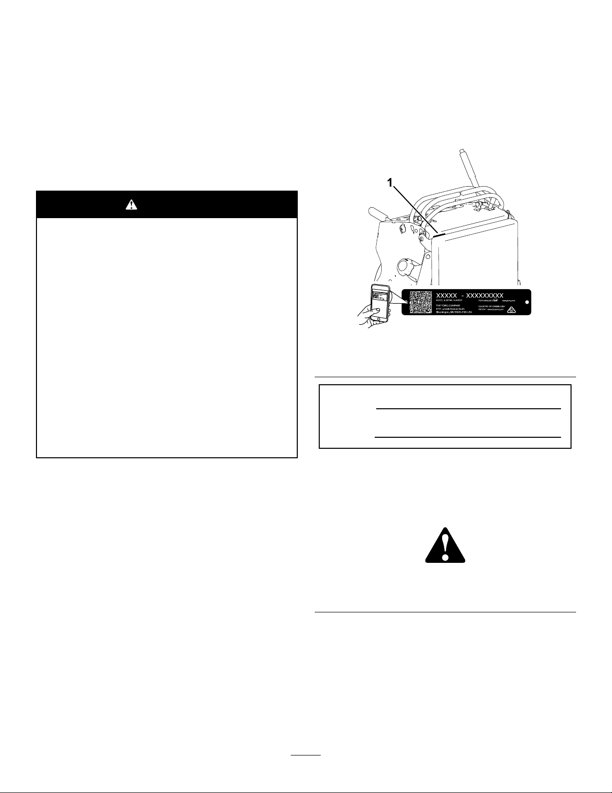
DealerorToroCustomerServiceandhavethemodel
andserialnumbersofyourproductready.Figure1
identiesthelocationofthemodelandserialnumbers
ontheproduct.Writethenumbersinthespace
provided.
Important:Withyourmobiledevice,youcan
scantheQRcodeontheserialnumberdecal(if
equipped)toaccesswarranty,parts,andother
productinformation.
g235457
Figure1
1.Locationofthemodelandserialnumbers
ModelNo.
SerialNo.
Introduction
Thisrotary-blade,stand-onlawnmowerisintended
tobeusedbyprofessional,hiredoperators.Itis
designedprimarilyforcuttinggrassonwell-maintained
lawnsonresidentialorcommercialproperties.Using
thisproductforpurposesotherthanitsintendeduse
couldprovedangeroustoyouandbystanders.
Readthisinformationcarefullytolearnhowtooperate
andmaintainyourproductproperlyandtoavoid
injuryandproductdamage.Y ouareresponsiblefor
operatingtheproductproperlyandsafely .
Visitwww.Toro.comformoreinformation,including
safetytips,trainingmaterials,accessoryinformation,
helpndingadealer,ortoregisteryourproduct.
Wheneveryouneedservice,genuineToroparts,or
additionalinformation,contactanAuthorizedService
©2020—TheToro®Company
8111LyndaleAvenueSouth
Bloomington,MN55420
Thismanualidentiespotentialhazardsandhas
safetymessagesidentiedbythesafety-alertsymbol
(Figure2),whichsignalsahazardthatmaycause
seriousinjuryordeathifyoudonotfollowthe
recommendedprecautions.
Figure2
1.Safety-alertsymbol
Thismanualuses2wordstohighlightinformation.
Importantcallsattentiontospecialmechanical
informationandNoteemphasizesgeneralinformation
worthyofspecialattention.
Contactusatwww.Toro.com.
2
g000502
PrintedintheUSA
AllRightsReserved

Contents
Safety.......................................................................4
GeneralSafety...................................................4
SafetyandInstructionalDecals..........................4
ProductOverview.....................................................9
Controls.............................................................9
Specications..................................................10
Attachments/Accessories.................................10
BeforeOperation..................................................11
BeforeOperationSafety....................................11
AddingFuel.......................................................11
PerformingDailyMaintenance..........................12
BreakinginaNewMachine..............................12
UsingtheSafety-InterlockSystem....................12
DuringOperation.................................................13
DuringOperationSafety...................................13
OperatingtheParkingBrake.............................15
OperatingtheMower-Blade-ControlSwitch
(PTO)............................................................15
OperatingtheThrottle.......................................16
OperatingtheChoke........................................16
OperatingtheIgnitionSwitch............................17
StartingtheEngine...........................................17
ShuttingOfftheEngine.....................................18
OperatingthePlatform......................................18
DrivingForwardorBackward............................19
SideDischargingorMulchingthe
Grass............................................................20
AdjustingtheHeight-of-Cut...............................21
AdjustingtheAnti-ScalpRollers........................21
AdjustingtheFlowBafe..................................21
PositioningtheFlowBafe................................22
UsingWeights..................................................23
AfterOperation....................................................23
AfterOperationSafety......................................23
UsingtheFuel-ShutoffValve.............................24
PushingtheMachinebyHand..........................24
TransportingtheMachine.................................25
Maintenance...........................................................27
MaintenanceSafety..........................................27
RecommendedMaintenanceSchedule(s)...........27
Pre-MaintenanceProcedures..............................28
ReleasingtheCushionforRearAccess............28
OpeningtheEngineGuard...............................29
Lubrication..........................................................29
GreasingtheMachine.......................................29
GreasingtheT orsionIdler.................................29
GreasingtheFrontCasterPivots......................30
GreasingtheCaster-WheelHubs.....................30
GreasingtheMotionControls...........................31
EngineMaintenance...........................................31
EngineSafety...................................................31
ServicingtheAirCleaner..................................31
ServicingtheEngineOil....................................32
ServicingtheSparkPlug...................................34
CheckingtheSparkArrester.............................35
FuelSystemMaintenance...................................36
DrainingtheFuelT ank......................................36
RemovingtheFuelT ank...................................36
ReplacingtheFuelFilter...................................37
ElectricalSystemMaintenance...........................37
ElectricalSystemSafety...................................37
ServicingtheBattery.........................................37
ServicingtheFuses..........................................39
DriveSystemMaintenance..................................40
AdjustingtheTracking......................................40
CheckingtheTirePressure...............................40
AdjustingtheCaster-PivotBearing...................41
ServicingtheCasterWheelsand
Bearings........................................................41
RemovingtheClutchShim...............................42
CheckingtheWheel-LugNuts..........................43
CoolingSystemMaintenance..............................44
CleaningtheAir-IntakeScreen.........................44
CleaningtheCoolingSystem............................44
BrakeMaintenance.............................................44
TestingtheParkingBrake.................................44
AdjustingtheBrakes.........................................44
BeltMaintenance................................................45
CheckingtheBelts............................................45
ReplacingtheMower-DeckBelt........................45
ReplacingtheTransmissionBelt......................46
ControlsSystemMaintenance.............................47
AdjustingtheMotion-ControlLevers.................47
HydraulicSystemMaintenance...........................48
HydraulicSystemSafety...................................48
HydraulicSystemSpecications.......................48
CheckingtheHydraulicFluid............................48
ReplacingtheHydraulicFluidand
Filters............................................................48
BleedingtheHydraulicSystem.........................49
MowerDeckMaintenance....................................50
BladeSafety.....................................................50
ServicingtheCuttingBlades.............................50
LevelingtheMowerDeck..................................52
AdjustingtheDeck-LiftSpring...........................54
ReplacingtheGrassDeector..........................55
Cleaning..............................................................55
CleaningundertheMowerDeck.......................55
DisposingofWaste...........................................55
Storage...................................................................56
StorageSafety..................................................56
CleaningandStorage.......................................56
Troubleshooting......................................................57
Schematics.............................................................59
3

Safety
Thismachinehasbeendesignedinaccordancewith
ANSIB71.4-2017.
GeneralSafety
Thisproductiscapableofamputatinghandsand
feetandofthrowingobjects.Alwaysfollowallsafety
instructionstoavoidseriouspersonalinjury.
•Readandunderstandthecontentsofthis
Operator’sManualbeforestartingtheengine.
•Donotputyourhandsorfeetnearmoving
componentsofthemachine.
•Donotoperatethemachinewithoutallguards
andothersafetyprotectivedevicesinplaceand
functioningproperlyonthemachine.
•Keepclearofthedischargeopening.
SafetyandInstructionalDecals
•Keepbystandersandchildrenoutoftheoperating
area.Donotallowchildrentooperatethemachine.
Allowonlypeoplewhoareresponsible,trained,
familiarwiththeinstructions,andphysically
capabletooperatethemachine.
•Stopthemachine,shutofftheengine,andremove
theignitionkeybeforeservicing,fueling,or
uncloggingthemachine.
Improperlyusingormaintainingthismachinecan
resultininjury.T oreducethepotentialforinjury,
complywiththesesafetyinstructionsandalways
payattentiontothesafety-alertsymbol
meansCaution,Warning,orDanger—personalsafety
instruction.Failuretocomplywiththeseinstructions
mayresultinpersonalinjuryordeath.
,which
Safetydecalsandinstructionsareeasilyvisibletotheoperatorandarelocatednearanyarea
ofpotentialdanger.Replaceanydecalthatisdamagedormissing.
decalbatterysymbols
BatterySymbols
Someorallofthesesymbolsareonyourbattery .
1.Explosionhazard6.Keepbystandersaway.
2.Nore,openames,or
smoking
3.Causticliquid/chemical
burnhazard
4.Weareyeprotection.9.Flusheyesimmediately
5.ReadtheOperator’s
Manual.
7.Weareye
protection—explosive
gasescancauseblindness
andotherinjuries.
8.Batteryacidcancause
severeburns.
withwaterandgetmedical
helpfast.
10.Containslead;donot
discard.
decaloemmarkt
Manufacturer'sMark
1.Thismarkindicatesthatthebladeisidentiedasapart
fromtheoriginalmachinemanufacturer.
decal106-5517
106-5517
1.Warning—donottouchthehotsurface.
4
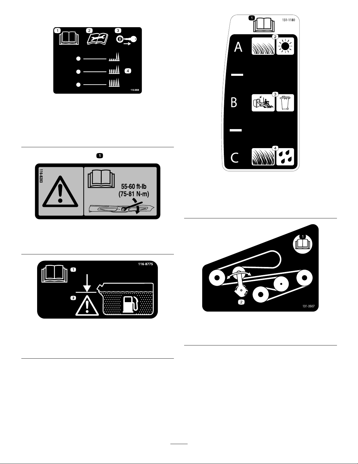
Decal112-3858isformachineswith60indecksonly.
decal112-3858
112-3858
1.ReadtheOperator's
Manual.
2.ReadtheOperator's
3.Removethekeybefore
adjustingtheheightofcut.
4.Height-of-cutsettings
Manualbeforeperforming
maintenance.
116-8283
1.Warning—readtheOperator'sManualforinstructionson
torquingthebladebolt/nutto75to81N∙m(55to60ft-lb).
decal131-1180
131-1180
1.ReadtheOperator's
Manual.
2.Short,lightgrass;dry
conditions
decal116-8283
3.Baggingsetting
4.Tall,densegrass;wet
conditions
1.ReadtheOperator’s
Manual.
116-8775
2.Warning—lltothebottom
ofthellerneck;donot
overllthetank.
decal131-3507
decal116-8775
1.ReadtheOperator's
131-3507
2.Belttensioner
Manual.
5

1.Heightofcut
131-3528
15A 15A 10A
7.5A
decal131-3521
131-3521
decal131-3529
131-3529
1.ReadtheOperator'sManualformoreinformationon
maintenanceintervalsandprocedures.
decal131-3524
131-3524
1.ReadtheOperator's
Manual.
2.Transmissionuid
1.Keyswitch—15A
2.Accessoryport—15A
3.Colduidlevel
131-3528
3.Powertakeoff(PTO)—10
4.Infocenter—7.5A
decal131-3536
131-3536
1.Battery4.Parkingbrake
2.Time5.Engine—start
3.Powertakeoff(PTO)
decal131-3528
A
6.Engagethehandlebars.
6

decal133-4641
133-4641
decal133-4604
133-4604
1.Warning—donotcarrypassengers.
1.Thrownobject
hazard—keepbystanders
awayfromthemachine.
2.Thrownobjecthazard,
opendeector—only
operatethemachinewith
adeectororagrass
collector.
3.Severinghazardofhand
orfoot—keepawayfrom
movingparts.
4.Entanglement
hazard—keepaway
frommovingparts;keep
allguardsandshieldsin
place.
131-3526
1.Powertakeoff(PTO)—disengaged
2.Fast6.Tractiondrive
3.Slow
4.Neutral
5.Reverse
7.Engagethehandles.
decal133-8062
133-8062
decal131-3526
decal139-2878
139-2878
1.Warning—readtheOperator’sManual.
2.Warning—alloperatorsshouldbetrainedbeforeoperating
themachine.
3.Warning—wearhearingprotection.8.Tippinghazard—donotusedualrampswhenloadingontoa
4.Thrownobjecthazard—lowerthedeectorbeforeoperating
themachine.
5.Cutting/dismembermenthazardofhandorfoot—stayaway
frommovingparts;keepallguardsandshieldsinplace.
6.Thrownobjecthazard—keepbystandersaway .
7.Warning—engagetheparkingbrake,shutofftheengine,and
removethekeybeforeleavingthemachineorperforming
maintenance.
trailer;use1rampwideenoughforthemachine;backup
therampwhenloadingthemachineanddriveforwardoffthe
rampwhenunloading.
9.Tippinghazard—donotusethemachineneardrop-offsor
onslopes;stayatleast2widthsofthemachineawayfrom
drop-offs.
7

decal140-4258
140-4258
1.Parkingbrake—disengaged
2.Parkingbrake—engaged
3.On
4.Off
5.Enginespeed—fast
6.Enginespeed—slow
8

ProductOverview
Controls
Becomefamiliarwithallthecontrols(Figure4)before
youstarttheengineandoperatethemachine.
ControlPanel
g332923
Figure3
1.Anti-scalproller(60-inch
decksonly)
2.Frontcasterwheel8.Fueltank
3.Grassdeector9.Platform(downposition)
4.Engine
5.Controlpanel
6.Motion-controllevers12.Mowerdeck
7.Hydraulictank
10.Fuel-shutoffvalve
11.Battery
Figure4
1.Fuelcap7.Keyswitch
2.Chokecontrol
3.Parking-brakelever
4.Hydraulic-tankcap
5.Hourmeter11.Motion-controllever
6.Power-takeoffswitch
(PTO)
8.Throttlecontrol
9.Height-of-cutlever
10.Height-of-cutpin
12.Referencebar
Power-TakeoffSwitch(PTO)
Usethepower-takeoffswitch(PTO)toengageand
disengagemowerbladesorstartandstoppowered
attachments(Figure4);refertoOperatingthe
Mower-Blade-ControlSwitch(PTO)(page15).
ThrottleControl
g300766
Thethrottlecontrolstheenginespeed,andithasa
continuous-variablesettingfromtheSLOWtoFAST
position(Figure4).
HourMeter
Thehourmeterrecordsthenumberofhoursthe
enginehasoperated.Itoperateswhentheengine
9

isrunning.Usethesetimesforschedulingregular
maintenance(Figure5).
Specications
Note:Specicationsanddesignaresubjectto
changewithoutnotice.
Figure5
1.Safety-interlocksymbols
2.Batterylight
3.Hourmeter
Safety-InterlockIndicators
Symbolsonthehourmeterindicatewithablack
trianglethattheinterlockcomponentisinthecorrect
position(Figure5).
Battery-IndicatorLight
IfyouturnthekeytotheONpositionforafew
seconds,thebatteryvoltagedisplaysinthearea
wherethehoursarenormallydisplayed.
Thebatterylightturnsonwhenyouturnthekeytothe
ONpositionandwhenthechargeisbelowthecorrect
operatinglevel(Figure5).
ChokeControl
Usethechokecontroltostartacoldengine.Pullthe
chokecontroluptoengageit.Pushdownonthe
chokecontroltodisengageit.
KeySwitch
48inMower
Deck
Cuttingwidth
deector
down
g009467
deector
raised
platform
down
platformup
122cm131cm152cm
(48inches)(52inches)(60inches)
161cm172cm193cm Widthwith
(64inches)(68inches)(76inches)
126cm137cm158cm Widthwith
(50inches)(54inches)(62inches)
191cm191cm201cm Lengthwith
(75inches)(75inches)(79inches)
145cm145cm164cm Lengthwith
(61inches)(61inches)(65inches)
122cm122cm122cm Height
(48inches)(48inches)(48inches)
401kg405kg412kg Weight
(884lb)(893lb)(909lb)
52inMower
Deck
60inMower
Deck
Attachments/Accessories
AselectionofT oroapprovedattachmentsand
accessoriesisavailableforusewiththemachine
toenhanceandexpanditscapabilities.Contact
yourAuthorizedServiceDealerorauthorizedT oro
distributororgotowww.Toro.comforalistofall
approvedattachmentsandaccessories.
Toensureoptimumperformanceandcontinuedsafety
certicationofthemachine,useonlygenuineToro
replacementpartsandaccessories.Replacement
partsandaccessoriesmadebyothermanufacturers
couldbedangerous,andsuchusecouldvoidthe
productwarranty.
Thekeyswitch,usedtostartandshutofftheengine,
has3positions:OFF,RUN,andSTART.Referto
OperatingtheIgnitionSwitch(page17).
Motion-ControlLevers
Usethemotion-controlleverstodrivethemachine
forward,reverse,andturneitherdirection(Figure4).
Fuel-ShutoffValve
Closethefuel-shutoffvalvewhentransportingor
storingthemachine;refertoUsingtheFuel-Shutoff
Valve(page24).
10

Operation
–Ifyouspillfuel,donotattempttostartthe
engine.Avoidcreatingasourceofignitionuntil
thefuelvaporshavedissipated.
BeforeOperation
BeforeOperationSafety
GeneralSafety
•Neverallowchildrenoruntrainedpeopletooperate
themachine.Localregulationsmayrestrictthe
ageoftheoperator.Theownerisresponsiblefor
trainingalloperatorsandmechanics.
•Becomefamiliarwiththesafeoperationofthe
equipment,operatorcontrols,andsafetysigns.
•Shutofftheengine,removethekey,andwait
forallmovingpartstostopbeforeleavingthe
operator’sposition.Allowthemachinetocool
beforeservicing,adjusting,fueling,cleaning,or
storingit.
•Knowhowtostopthemachineandshutoffthe
enginequickly.
•Checkthatoperator-presencecontrols,safety
switches,andguardsareattachedandfunctioning
properly.Donotoperatethemachineunlessthey
arefunctioningproperly.
•Beforemowing,alwaysinspectthemachineto
ensurethattheblades,bladebolts,andcutting
assembliesareingoodworkingcondition.
•Inspecttheareawhereyouwillusethemachine
andremoveallobjectsthatthemachinecould
throw.
•Evaluatetheterraintodeterminetheappropriate
equipmentandanyattachmentsoraccessories
requiredtooperatethemachineproperlyand
safely.
–Storefuelinanapprovedcontainerandkeep
itoutofthereachofchildren.
•Fuelisharmfulorfatalifswallowed.Long-term
exposuretovaporscancauseseriousinjuryand
illness.
–Avoidprolongedbreathingofvapors.
–Keepyourhandsandfaceawayfromthe
nozzleandthefuel-tankopening.
–Keepfuelawayfromyoureyesandskin.
•Donotstorethemachineorfuelcontainerwhere
thereisanopename,spark,orpilotlight,such
asonawaterheateroronotherappliances.
•Donotllcontainersinsideavehicleoronatruck
ortrailerbedwithaplasticliner.Alwaysplace
containersontheground,awayfromyourvehicle
beforelling.
•Removetheequipmentfromthetruckortrailer
andrefuelitwhileitisontheground.Ifthisisnot
possible,thenrefuelfromaportablecontainer
ratherthanafuel-dispensernozzle.
•Donotoperatethemachinewithouttheentire
exhaustsysteminplaceandinproperworking
condition.
•Keepthefuel-dispensernozzleincontactwith
therimofthefueltankorcontaineropeningat
alltimesuntilfuelingiscomplete.Donotusea
nozzlelock-opendevice.
•Ifyouspillfuelonyourclothing,changeyour
clothingimmediately.Wipeupanyfuelthatspills.
•Neveroverllthefueltank.Replacethefuelcap
andtightenitsecurely.
FuelSafety
•Fuelisextremelyammableandhighlyexplosive.
Areorexplosionfromfuelcanburnyouand
othersandcandamageproperty.
–Topreventastaticchargefromignitingthefuel,
placethecontainerand/ormachinedirectlyon
thegroundbeforelling,notinavehicleoron
anobject.
–Fillthefueltankoutdoors,inanopenarea,
whentheengineiscold.Wipeupanyfuelthat
spills.
–Donothandlefuelwhensmokingoraroundan
openameorsparks.
–Donotremovethefuelcaporaddfueltothe
tankwhiletheengineisrunningorhot.
AddingFuel
RecommendedFuel
•Forbestresults,useonlyclean,fresh(lessthan
30daysold),unleadedgasolinewithanoctane
ratingof87orhigher((R+M)/2ratingmethod).
•Ethanol:Gasolinewithupto10%ethanol
(gasohol)or15%MTBE(methyltertiarybutyl
ether)byvolumeisacceptable.Ethanoland
MTBEarenotthesame.Gasolinewith15%
ethanol(E15)byvolumeisnotapprovedforuse.
Neverusegasolinethatcontainsmorethan
10%ethanolbyvolume,suchasE15(contains
15%ethanol),E20(contains20%ethanol),orE85
(containsupto85%ethanol).Usingunapproved
gasolinemaycauseperformanceproblemsand/or
11
enginedamagewhichmaynotbecoveredunder
warranty.
•Donotusegasolinecontainingmethanol.
•Donotstorefueleitherinthefueltankorfuel
containersoverthewinterunlessyouuseafuel
stabilizer.
•Donotaddoiltogasoline.
PerformingDaily
Maintenance
Beforestartingthemachineeachday ,performthe
EachUse/DailyprocedureslistedinMaintenance
(page27).
UsingStabilizer/Conditioner
Usefuelstabilizer/conditionerinthemachinetokeep
thefuelfreshlongerwhenusedasdirectedbythe
fuel-stabilizermanufacturer.
Important:Donotusefueladditivescontaining
methanolorethanol.
Addtheamountoffuelstabilizer/conditionertofresh
fuelasdirectedbythefuel-stabilizermanufacturer.
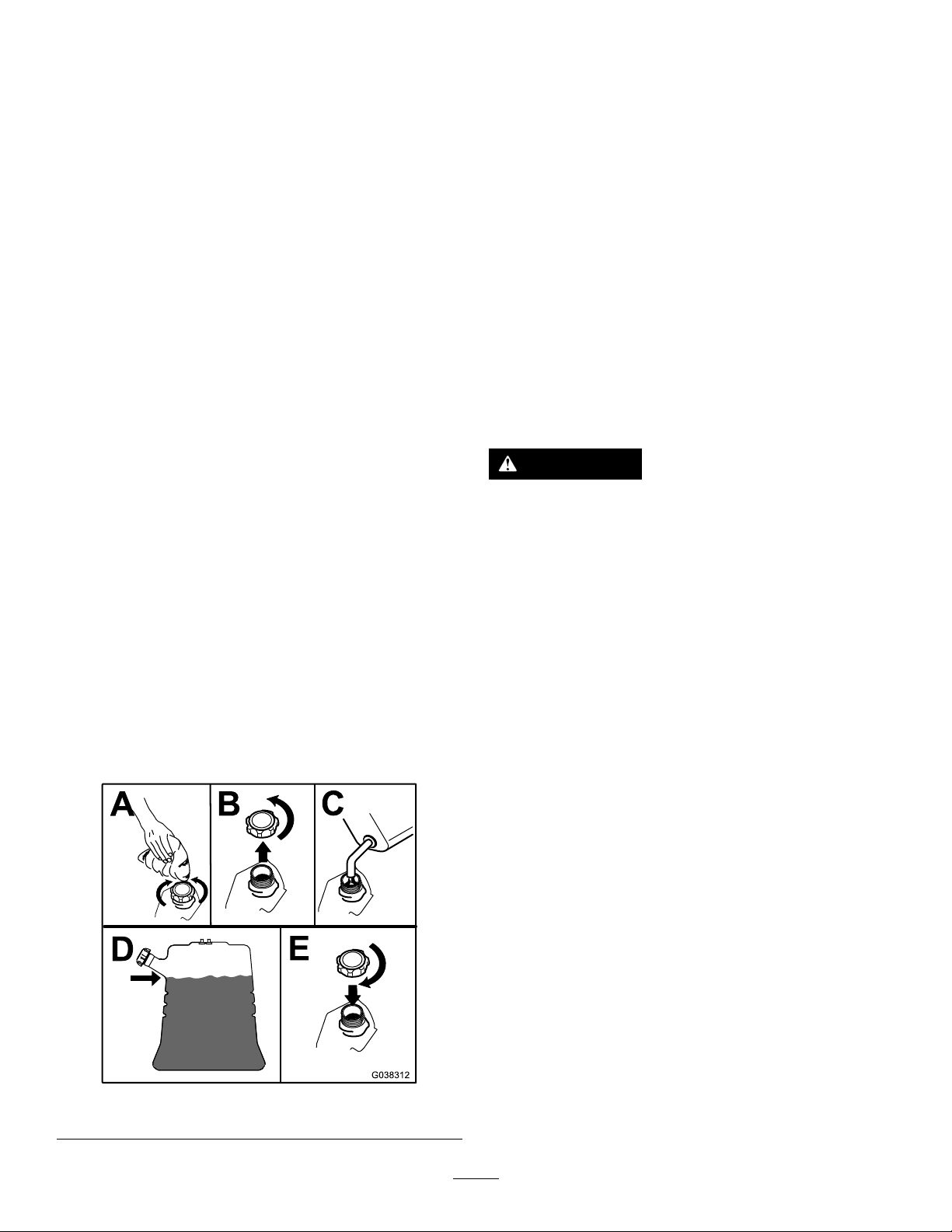
FillingtheFuelTank
1.Parkthemachineonalevelsurface,disengage
thePTO,movethemotion-controlleverstothe
NEUTRAL-LOCKposition,andengagetheparking
brake.
2.Shutofftheengine,removethekey,andwait
forallmovingpartstostopbeforeleavingthe
operatingposition.
3.Cleanaroundthefuel-tankcapandremovethe
cap.
4.Fillthefueltanktothebottomofthellerneck.
BreakinginaNewMachine
Newenginestaketimetodevelopfullpower.Mower
decksanddrivesystemshavehigherfrictionwhen
new,placingadditionalloadontheengine.Allow
40to50hoursofbreak-intimefornewmachinesto
developfullpowerandbestperformance.
UsingtheSafety-Interlock
System
WARNING
Ifsafety-interlockswitchesaredisconnected
ordamaged,themachinecouldoperate
unexpectedly,causingpersonalinjury.
•Donottamperwiththeinterlockswitches.
•Checktheoperationoftheinterlock
switchesdaily,andreplaceanydamaged
switchesbeforeoperatingthemachine.
Note:Donotllthefueltankcompletelyfull.
Theemptyspaceinthetankallowsthefuelto
expand.
5.Installthefuel-tankcapsecurely.Wipeupany
spilledfuel.
Figure6
Understandingthe
Safety-InterlockSystem
Thesafety-interlocksystemisdesignedtoprevent
PTOfromengagingunlessyoudo1ofthefollowing:
•Moveeithermotion-controllevertothecenter,
unlockedposition.
•PresstheONpositiononthePTOswitch.
Thesafety-interlocksystemisdesignedtostop
theblades/attachmentifyoumoveorrelease
bothmotion-controlleversintotheNEUTRAL-LOCK
position.
Thehourmeterhassymbolstonotifytheuser
wheneachinterlockcomponentisinthecorrect
position.Whenthecomponentisinthecorrect
position,atrianglelightsupinthecorresponding
square(Figure7).
g038312
12

Figure7
Note:Theclutchandblades/attachmentshould
engage.
9.PresstheOFFpositiononthePTOswitch.
Note:Theblades/attachmentshouldstop.
10.Withtheenginerunning,presstheONposition
onthePTOswitchwithoutholdingeither
motion-controllevertothecenter,unlocked
position.
Note:Theblades/attachmentshouldnot
g031282
engage.
1.Thetriangleslightupwhentheinterlockcomponentsare
inthecorrectposition.
TestingtheSafety-Interlock
System
ServiceInterval:Beforeeachuseordaily
Testthesafety-interlocksystembeforeyouusethe
machineeachtime.
Note:Ifthesafetysystemdoesnotoperateas
describedbelow,haveanAuthorizedServiceDealer
repairthesafetysystemimmediately.
1.Starttheengine;refertoStartingtheEngine
(page17).
2.Movethemotion-controlleverstothecenter,
unlockedposition.
Note:Theblades/attachmentshouldstopand
theengineshouldstoprunning.
3.Starttheengineanddisengagetheparking
brake.
4.Moveeithermotion-controllevertothecenter,
unlockedposition.
5.Continueholdingthemotion-controlleverin
thecenter,unlockedpositionandpresstheON
positiononthePTOswitch.
Note:Theclutchandblades/attachmentshould
engage.
6.Moveorreleasethemotion-controlleversinto
theNEUTRAL-LOCKposition.
Note:Theblades/attachmentshouldstopand
theengineshouldcontinuetorun.
7.PresstheOFFpositiononthePTOswitchand
moveeithermotion-controllevertothecenter,
unlockedposition.
8.Continueholdingthemotion-controlleverin
thecenter,unlockedpositionandpresstheON
positiononthePTOswitch.
DuringOperation
DuringOperationSafety
GeneralSafety
•Theowner/operatorcanpreventandisresponsible
foraccidentsthatmaycausepersonalinjuryor
propertydamage.
•Wearappropriateclothing,includingeye
protection;longpants;substantial,slip-resistant
footwear;andhearingprotection.Tiebacklong
hairanddonotwearlooseclothingorloose
jewelry.
•Useyourfullattentionwhileoperatingthe
machine.Donotengageinanyactivitythat
causesdistractions;otherwise,injuryorproperty
damagemayoccur.
•Donotoperatethemachinewhileill,tired,or
undertheinuenceofalcoholordrugs.
•Nevercarrypassengersonthemachineandkeep
bystandersandpetsawayfromthemachine
duringoperation.
•Operatethemachineonlyingoodvisibilityand
appropriateweatherconditions.Donotoperate
themachinewhenthereistheriskoflightning.
•Wetgrassorleavescancauseseriousinjuryif
youslipandcontacttheblade.Avoidmowingin
wetconditions.
•Beforeyoustarttheengine,ensurethatalldrives
areinneutral,theparkingbrakeisengaged,and
youareintheoperatingposition.
•Ensurethatyouhavegoodfootingwhileusingthis
machine,especiallywhenbackingup.
•Keepyourhandsandfeetawayfromthecutting
units.Keepclearofthedischargeopeningatall
times.
•Lookbehindanddownbeforebackinguptobe
sureofaclearpath.
•Useextremecarewhenapproachingblind
corners,shrubs,trees,orotherobjectsthatmay
blockyourview.
13

•Stopthebladeswheneveryouarenotmowing.
•Stopthemachine,removetheignitionkey,and
waitforallmovingpartstostopbeforeinspecting
themowerdeckorattachmentafterstrikingan
objectorifthereisanabnormalvibrationinthe
machine.Makeallnecessaryrepairsbefore
resumingoperation.
•Slowdownandusecautionwhenmakingturns
andcrossingroadsandsidewalkswiththe
machine.Alwaysyieldtheright-of-way.
•Disengagethecuttingunitandshutofftheengine
beforeadjustingtheheightofcut(unlessyoucan
adjustitfromtheoperatingposition).
•Operatetheengineonlyinwell-ventilatedareas.
Exhaustgasescontaincarbonmonoxide,which
islethalifinhaled.
•Neverleavearunningmachineunattended.
•Beforeleavingtheoperatingposition(including
toemptythecatchersortounclogthechute),do
thefollowing:
–Parkthemachineonalevelsurface.
–Disengagethepowertake-off.
–Engagetheparkingbrake.
–Shutofftheengineandremovetheignitionkey.
–Waitforallmovingpartstostop.
•Shutoffthemachineanddisengagethedriveto
thecuttingunitinthefollowingsituations:
–Beforefueling
–Beforeclearingblockages
–Beforechecking,cleaning,ormaintainingthe
cuttingunit
–Afterstrikingaforeignobjectorifanabnormal
vibrationoccurs.Inspectthecuttingunitfor
damageandmakerepairsbeforestartingand
operatingthemachine
–Beforeleavingtheoperatingposition
–Evaluatethesiteconditionsofthedayto
determineiftheslopeissafeformachine
operation.Usecommonsenseandgood
judgmentwhenperformingthisevaluation.
Changesintheterrain,suchasmoisture,can
quicklyaffecttheoperationofthemachineon
aslope.
•Operateacrossslopes,neverupanddown.Avoid
operationonexcessivelysteeporwetslopes.
•Identifyhazardsatthebaseoftheslope.Do
notoperatethemachineneardrop-offs,ditches,
embankments,water,orotherhazards.The
machinecouldsuddenlyrolloverifawheelgoes
overtheedgeortheedgecollapses.Keepasafe
distance(twicethewidthofthemachine)between
themachineandanyhazard.Useawalk-behind
machineorahandheldtooltooperateinthese
areas.
•Avoidstarting,stopping,orturningthemachineon
slopes.Avoidmakingsuddenchangesinspeedor
direction;turnslowlyandgradually.
•Donotoperateamachineunderanyconditions
wheretraction,steeringorstabilityisinquestion.
Beawarethatoperatingthemachineonwet
grass,acrossslopesordownhillmaycausethe
machinetolosetraction.Lossoftractiontothe
drivewheelsmayresultinslidingandalossof
brakingandsteering.Themachinecanslideeven
ifthedrivewheelsarestopped.
•Removeormarkobstaclessuchasditches,holes,
ruts,bumps,rocks,orotherhiddenhazards.T all
grasscanhideobstacles.Uneventerraincould
overturnthemachine.
•Useextracarewhileoperatingwithaccessoriesor
attachments.Thesecanchangethestabilityof
themachineandcausealossofcontrol.Follow
directionsforcounterweights.
•Ifyoulosecontrolofthemachine,stepoffand
awayfromthedirectionoftravelofthemachine.
•Donotusethemachineasatowingvehicle.
•Useonlyaccessoriesandattachmentsapproved
byTheT oro®Company.
SlopeSafety
•Slopesareamajorfactorrelatedtolossofcontrol
androlloveraccidents,whichcanresultinsevere
injuryordeath.Youareresponsibleforsafeslope
operation.Operatingthemachineonanyslope
requiresextracaution.Beforeusingthemachine
onaslope,dothefollowing:
–Reviewandunderstandtheslopeinstructions
inthemanualandonthemachine.
14
OperatingtheParking
Operatingthe
Brake
Alwaysengagetheparkingbrakewhenyoushutoff
themachineorleaveitunattended.Beforeeachuse,
checktheparkingbrakeforproperoperation.
Iftheparkingbrakedoesnotholdsecurely,adjustit;
refertoAdjustingtheBrakes(page44).
Pulltheparking-brakeleverrearwardtoengageit
(Figure8).
Pushtheparking-brakeleverforwardtodisengageit.
Figure8
1.Parkingbrake—engaged2.Parking
brake—disengaged
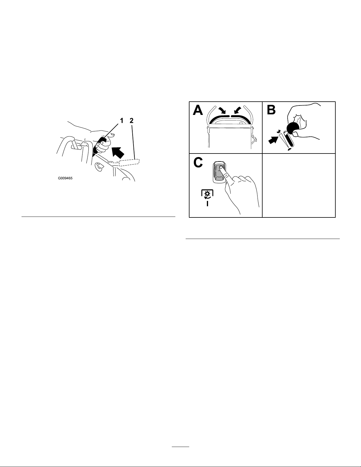
Mower-Blade-Control
Switch(PTO)
Usetheblade-controlswitch(PTO)inconjunctionwith
themotion-controlleverstoengageanddisengage
themowerblades.
EngagingtheMowerBlades(PTO)
g009465
Figure9
g301277
15
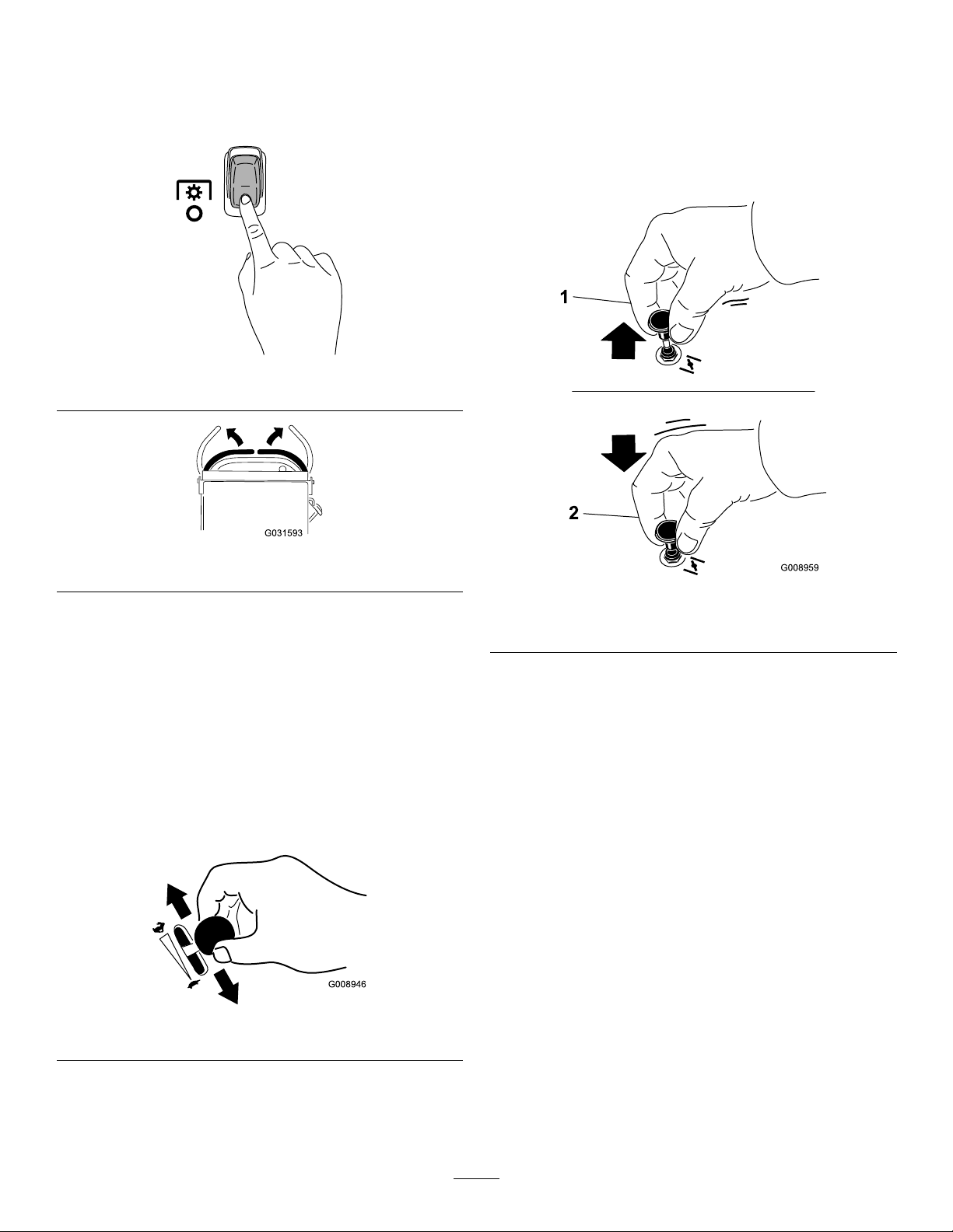
DisengagingtheMowerBlades
(PTO)
Figure10andFigure11show2waystodisengage
themowerblades.
Figure10
OperatingtheChoke
Usethechoketostartacoldengine.
1.Pullupthechokeknobtoengagethechoke
beforeusingthekeyswitch(Figure13).
2.Pushdownthechokeknobtodisengagethe
chokeaftertheenginehasstarted(Figure13).
g301401
Figure11
Note:Ifyoudisengagethemowerbladesby
releasingthemotion-controllevers,youcanengage
thebladesagainbypressingtheONpositionofthe
switch(Figure9)withoutpressingtheOFFposition
rst.
OperatingtheThrottle
YoucanmovethethrottlecontrolbetweenFASTand
SLOWpositions(Figure12).
AlwaysusetheFASTpositionwhenengagingthePTO.
g031593
g008959
Figure13
1.ONposition2.OFFposition
Figure12
g008946
16
OperatingtheIgnition
StartingtheEngine
Switch
Important:Donotengagethestarterformore
than5secondsatatime.Iftheenginefailsto
start,wait15secondsbetweenattempts.Failure
tofollowtheseinstructionscanburnoutthe
startermotor.
Note:Youmayneedtorepeatthecycleforstarting
theenginewhenyoustartitforthersttimeafteryou
havelledacompletelyemptyfuelsystemwithfuel.
Figure14
Important:Donotengagethestarterformore
than5secondsatatime.Iftheenginefailsto
start,wait15secondsbetweenattempts.Failure
tofollowtheseinstructionscanburnoutthe
startermotor.
Note:Youmayneedtorepeatthecycleforstarting
theenginewhenyoustartitforthersttimeafteryou
havelledacompletelyemptyfuelsystemwithfuel.
g031239
Figure15
g031281
g301289
Figure16
17

ShuttingOfftheEngine
CAUTION
Childrenorbystandersmaybeinjuredifthey
moveorattempttooperatethemachinewhile
itisunattended.
Alwaysremovethekeyandengagethe
parkingbrakewhenleavingtheoperator’s
position.
OperatingthePlatform
Youcanusethemachinewiththeplatforminthe
upordownposition.Itisyourpreferenceonwhich
positiontouse.
WARNING
Theoperatorplatformisheavyandmaycause
injurywhenyouraiseorlowerit.Carefully
lowerorraisetheoperatorplatform,as
suddenlydroppingitcouldinjureyou.
Lettheengineidleatslowthrottle(turtle)for60
secondsbeforeturningthekeyswitchtotheOFF
position.
•Donotputyourhandsorngersinthe
platform-pivotareawhenloweringor
raisingtheoperatorplatform.
•Makesurethattheplatformissupported
whenyoupullthelatchpinout.
•Makesurethatthelatchsecuresthe
platformwhenfoldingitup.Pushittight
againstthecushionforthelatchpinto
lockintoplace.
•Keepbystandersawayfromthemachine
whenraisingorloweringtheplatform.
OperatingtheMachinewiththe
PlatformUp
Operatethemachinewiththeplatformupforthe
followingconditions:
•Usingthemachineneardrop-offs
•Usingthemachineinsmallareaswherethe
machineistoolarge
•Areaswithlow-hangingbranchesorobstacles
•Loadingthemachinefortransport
•Drivingupslopes
Figure17
Important:Makesurethatthefuel-shutoffvalve
isclosedbeforetransportingorstoringthe
machinetopreventafuelleak.Beforestoringthe
machine,disconnectthesparkplug(s)toprevent
thepossibilityofaccidentalstarting.
Toraisetheplatform,pullthebackoftheplatformup
g301288
sothatthelatchpinandknoblockitintoplace.Push
ittightagainstthecushionforthelatchpintolockit
intoplace.
OperatingtheMachinewiththe
PlatformDown
Operatethemachinewiththeplatformdownforthe
followingconditions:
•Usingthemachineinmostareas
•Drivingacrossslopes
•Drivingdownslopes
Tolowertheplatform,pushtheplatformforward
againstthecushiontoreleasepressureonthelatch
pin,thenpulltheknoboutandlowertheplatform
(Figure18).
18

Figure18
DrivingForward
1.Disengagetheparkingbrake;refertoOperating
theParkingBrake(page15).
2.Movethemotion-controlleverstothecenter,
unlockedposition.
g031026
1.Platformup
2.Platformdown
3.Pulltheknobouttorelease
theplatform.
DrivingForwardor
Backward
Thethrottlecontrolregulatestheenginespeedas
measuredinrpm(revolutionsperminute).Place
thethrottlecontrolintheFASTpositionforbest
performance.
Important:Backthemachineovercurbs,1wheel
atatime;drivingitforwardovercurbscould
damagethemachine.
CAUTION
Themachinecanspinveryrapidly,andyou
maylosecontrolofthemachine,causing
personalinjurytoyouanddamagetothe
machine.
Figure19
1.Frontreferencebar
2.Leftcontrollever
3.Rearreferencebar6.Leftcontrolleverinthe
4.Rightcontrollever
5.Rightcontrolleverinthe
NEUTRAL-LOCKposition
NEUTRAL-LOCKposition
3.Slowlypushthemotion-controlleversforward
(Figure20).
Note:Theengineshutsoffifyoumovea
motion-controlleverwhiletheparkingbrakeis
engaged.
Note:Thefartheryoumovethemotion-control
leversineitherdirection,thefasterthemachine
movesinthatdirection.
Note:T ostop,pullthemotion-controllevers
backtotheNEUTRALposition.
g030983
Slowdownthemachinebeforemakingsharp
turns.
19
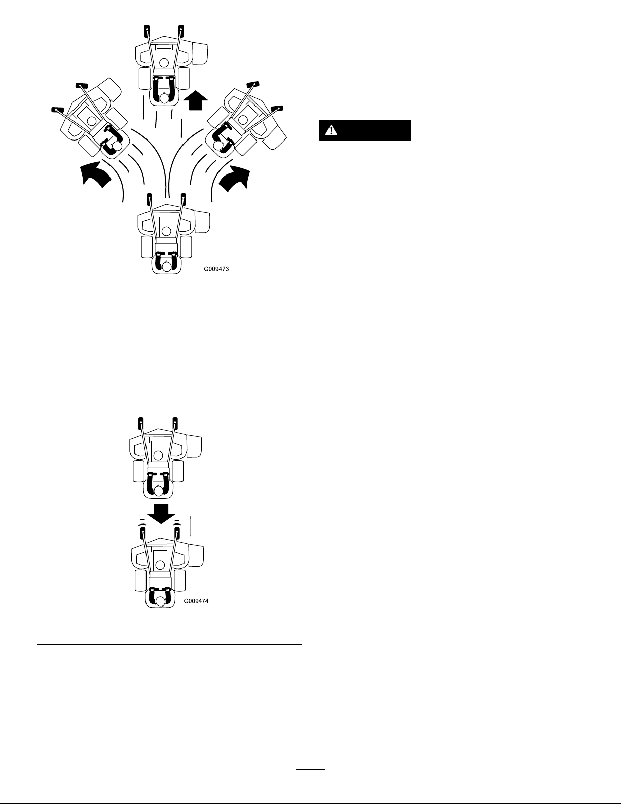
Figure20
SideDischargingor
MulchingtheGrass
Thismachinehasahingedgrassdeectorthat
dispersesclippingstothesideanddowntowardthe
turf.
DANGER
Withoutthegrassdeector,dischargecover,
orcompletegrasscatcherassemblymounted
inplace,youandothersareexposedtoblade
contactandthrowndebris.Contactwith
rotatingmowerblade(s)andthrowndebris
causeinjuryordeath.
•Donotremovethegrassdeectorfrom
themachine,becausethegrassdeector
routesmaterialdowntowardtheturf.Ifthe
g009473
grassdeectoriseverdamaged,replaceit
immediately.
•Neverputyourhandsorfeetunderthe
machine.
DrivingBackward
1.Movebothmotion-controlleverstothecenter,
unlockedposition.
2.Slowlypullthemotion-controlleversrearward
(Figure21).
Figure21
•Nevertrytoclearthedischargeareaor
mowerbladesunlessyoureleasethebail
andthepowertakeoff(PTO)isoff.Rotate
thekeytotheOFFposition.Alsoremove
thekeyanddisconnectthewire(s)from
thesparkplug(s).
g009474
20

AdjustingtheHeight-of-Cut
AdjustingtheAnti-Scalp
Theheight-of-cutcanbeadjustedfrom38to127mm
(1-1/2to5inches)in6mm(1/4inch)increments.
Note:Usingaheight-of-cutunder51mm(2inches)
increasesthewearonthemower-deckbelt.Usea
height-of-cutthatisgreaterthan51mm(2inches)
wheneverpossible.
Rollers
Modelswitha60-InchDeckOnly
Wheneveryouchangetheheight-of-cut,adjustthe
heightoftheanti-scalprollers.
1.Disengagetheblade-controlswitch(PTO),move
themotion-controlleverstotheNEUTRAL-LOCK
position,andengagetheparkingbrake.
2.Shutofftheengine,removethekey,andwait
forallmovingpartstostopbeforeleavingthe
operatingposition.
3.Removethenutandboltpositiontheanti-scalp
rollersandinstallthenutandbolt.
4.Ensurethatthespacersandbushingsare
installed(Figure23).
Figure22
g018324
Figure23
1.Bushing4.Bolt
2.Anti-scalproller5.Nut
3.Spacer
AdjustingtheFlowBafe
Youcanadjustthemower-dischargeowfordifferent
typesofmowingconditions.Positionthecamlock
andbafetoprovidethebestqualityofcut.
g267253
1.DisengagethePTO,movethemotion-control
leverstotheNEUTRAL-LOCKposition,and
engagetheparkingbrake.
2.Shutofftheengine,removethekey,andwait
forallmovingpartstostopbeforeleavingthe
operatingposition.
3.Toadjustthebafe,loosentheknob(Figure24).
4.Adjustthebafeandknobintheslottothe
desireddischargeowandtightentheknob.
21

Figure24
PositionB
Usethispositionwhenbagging(Figure26).
g301806
1.Slot
2.Knob
PositioningtheFlowBafe
Thefollowingguresareforrecommendeduseonly.
Adjustmentsvarybygrasstype,moisturecontent,
andtheheightofthegrass.
Note:Iftheenginepowerdrawsdownandthe
mowergroundspeedisthesame,openthebafe.
PositionA
Thisisthefull,rearposition(seeFigure25).Usethis
positionforthefollowing:
•Inshort,lightgrassmowingconditions
•Indryconditions
•Smallergrassclippings
•Propelsgrassclippingsfartherawayfromthe
mower
g012678
Figure26
PositionC
Thisisthefull,openposition(Figure27).Usethis
positionforthefollowing:
•Intall,densegrassmowingconditions
•Inwetconditions
•Lowerstheengine-powerconsumption
•Allowsincreasedgroundspeedinheavyconditions
Figure25
g012679
Figure27
g012677
22

UsingWeights
•Installweightstoimprovebalance.Youcanaddor
removeweightstocreateoptimizedperformance
underdifferentoperatingconditionsandforyour
preference.
AfterOperation
AfterOperationSafety
•Addorremoveweights1atatimeuntilyou
achievethedesiredhandlingandbalance.
•RefertotheOperator’sManualofattachmentsfor
recommendedweights.
Note:ContactanAuthorizedServiceDealertoorder
aweightkit.
WARNING
Excessiveweightchangescanaffectthe
handlingandoperationofthemachine.
Thiscouldcauseseriousinjurytoyouor
bystanders.
•Makeweightchangesinsmallincrements
only.
•Evaluatethemachineaftereachweight
changetoensurethatyoucanoperatethe
machinesafely.
GeneralSafety
•Alwaysshutoffthemachine,removetheignition
key,waitforallmovingpartstostop,andallow
themachinetocoolbeforeadjusting,servicing,
cleaning,orstoringit.
•Cleangrassanddebrisfromthecuttingunits,
mufers,andenginecompartmenttohelpprevent
res.Cleanupoilorfuelspills.
•Shutoffthefuelbeforestoringortransportingthe
machine.
•DisengagethePTOwheneveryouaretransporting
ornotusingthemachine.
•Neverstorethemachineorfuelcontainerwhere
thereisanopename,spark,orpilotlight,such
asonawaterheateroronotherappliances.
•Usefull-widthrampsforloadingthemachineinto
atrailerortruck.
•Tiethemachinedownsecurelyusingstraps,
chains,cable,orropes.Bothfrontandrearstraps
shouldbedirecteddownandoutwardfromthe
machine.
23

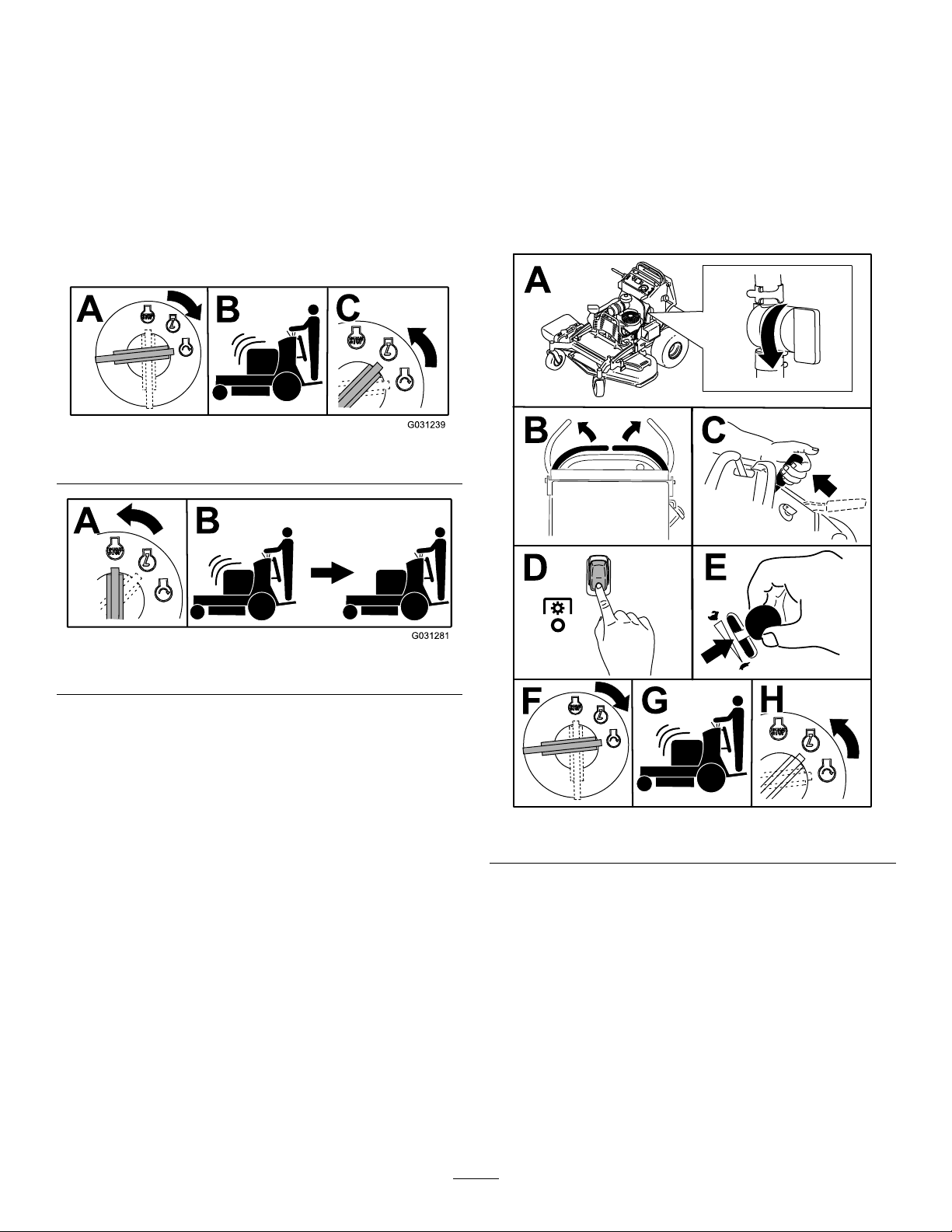
UsingtheFuel-Shutoff
PushingtheMachineby
Valve
Closethefuel-shutoffvalvefortransport,maintenance,
andstorage(Figure28).
Ensurethatthefuel-shutoffvalveisopenwhen
startingtheengine.
Hand
Thebypassvalvesallowyoutopushthemachineby
handwithouttheenginerunning.
Important:Alwayspushthemachinebyhand.
Donottowthemachine,becausehydraulic
damagemayoccur.
Important:Donotstartoroperatethemachine
withthebypassvalvesopen.Damagetosystem
mayoccur.
g031237
Figure28
1.ONposition2.OFFposition
g031238
g301290
Figure29
24

TransportingtheMachine
Useaheavy-dutytrailerortrucktotransportthe
machine.Useafull-widthramp.Ensurethatthetrailer
ortruckhasallthenecessarybrakes,lighting,and
markingasrequiredbylaw.Pleasecarefullyreadall
thesafetyinstructions.Knowingthisinformationcould
helpyouorbystandersavoidinjury.Refertoyour
localordinancesfortrailerandtie-downrequirements.
WARNING
Drivingonthestreetorroadwaywithout
turnsignals,lights,reectivemarkings,ora
slow-moving-vehicleemblemisdangerous
andcanleadtoaccidents,causingpersonal
injury.
Donotdrivethemachineonapublicstreet
orroadway.
SelectingaTrailer
WARNING
Loadingamachineontoatrailerortruck
increasesthepossibilityoftip-overandcould
causeseriousinjuryordeath(Figure30).
•Useonlyafull-widthramp;donotuse
individualrampsforeachsideofthe
machine.
•Ensurethatthelengthoframpisatleast4
timesaslongastheheightofthetraileror
truckbedtotheground.
Figure30
1.Full-widthrampinstowed
position
2.Rampisatleast4times
aslongastheheightof
thetrailerortruckbedto
theground
3.H=heightofthetraileror
truckbedtotheground
4.Trailer
LoadingtheMachine
WARNING
Loadingamachineontoatrailerortruck
increasesthepossibilityoftip-overandcould
causeseriousinjuryordeath.
•Useextremecautionwhenoperatinga
machineonaramp.
•Backthemachineuptherampandwalkit
forwarddowntheramp.
g229507
•Avoidsuddenaccelerationordeceleration
whiledrivingthemachineonarampas
thiscouldcausealossofcontrolora
tip-oversituation.
1.Ifusingatrailer,connectittothetowingvehicle
andconnectthesafetychains.
2.Ifapplicable,connectthetrailerbrakesand
lights.
3.Lowertheramp(Figure30).
4.Raisetheplatform.
Important:Alwayskeeptheplatformup
whenloadingandunloadingthemachine.
5.Backthemachineuptheramp(Figure31).
25
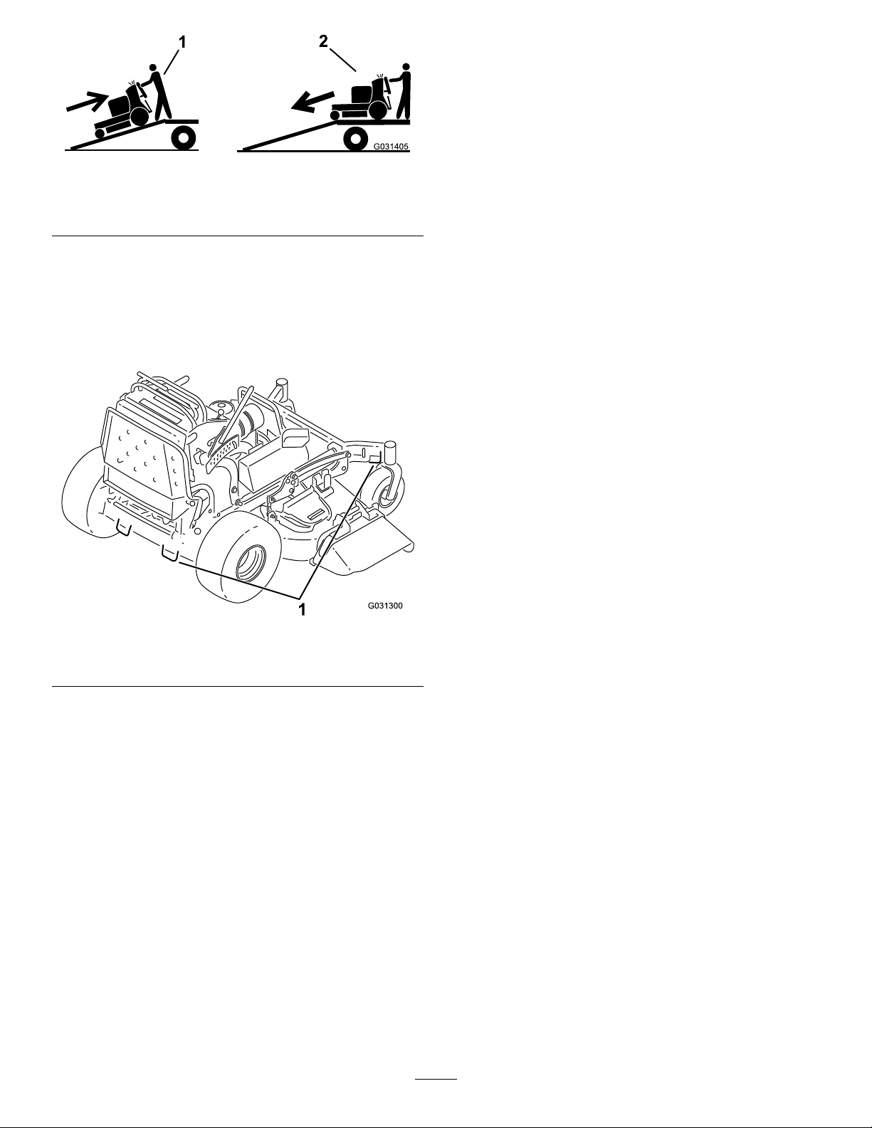
Figure31
g031405
1.Backthemachineupthe
ramp.
2.Walkthemachinedown
theramp.
6.Shutofftheengine,removethekey,andengage
theparkingbrake.
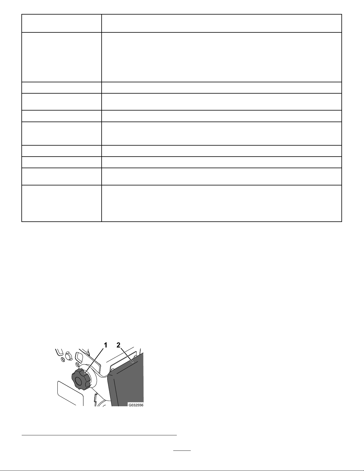
7.Tiedownthemachinenearthefrontcaster
wheelsandtherearbumperwithstraps,chains,
cable,orropes(Figure32).Refertolocal
regulationsfortie-downrequirements.
1.Tie-downloops
g031300
Figure32
26

Maintenance
Note:Determinetheleftandrightsidesofthemachinefromthenormaloperatingposition.
CAUTION
Ifyouleavetheignitionkeyintheswitch,someonecouldaccidentlystarttheengineand
seriousinjureyouorotherbystanders.
Removetheignitionkeyfromtheswitchbeforeyouperformanymaintenance.
MaintenanceSafety
•Beforeadjusting,cleaning,servicing,orleaving
themachine,dothefollowing:
–Parkthemachineonalevelsurface.
–Disengagethedrives.
–Engagetheparkingbrake.
–Shutofftheengineandremovetheignitionkey.
–Waitforallmovingpartstostop.
–Allowmachinecomponentstocoolbefore
performingmaintenance.
•Donotallowuntrainedpersonneltoservicethe
machine.
•Keepyourhandsandfeetawayfrommoving
parts.Ifpossible,donotmakeadjustmentswith
theenginerunning.
•Carefullyreleasepressurefromcomponentswith
storedenergy.
•Checktheparkingbrakeoperationfrequently.
Adjustandservicethebrakeasneeded.
•Nevertamperwithsafetydevices.Checktheir
properoperationregularly.
•Cleangrassanddebrisfromthecuttingunit,
drives,mufer,andenginetohelppreventres.
Cleanupoilorfuelspills.
•Checkthegrasscatchercomponentsfrequently
andreplacethemwhentheyarewornordamaged.
•Donotrelyonahydraulicsystemtosupportthe
machine;supportthemachinewithjackstands
wheneveryouraisethemachine.
•Keepallpartsingoodworkingconditionandall
hydraulicttingstight.Replaceallworn,damaged,
ormissingpartsanddecals.Keepallfasteners
tighttoensurethatthemachineisinsafeworking
condition.
•Toensureoptimumperformanceandcontinued
safetycerticationofthemachine,useonly
genuineT ororeplacementpartsandaccessories.
Replacementpartsandaccessoriesmadeby
othermanufacturerscouldbedangerous,and
suchusecouldvoidtheproductwarranty.
RecommendedMaintenanceSchedule(s)
MaintenanceService
Interval
Aftertherst8hours
Aftertherst50hours
Aftertherst100hours
Beforeeachuseordaily
Every50hours
MaintenanceProcedure
•Changetheengineoil.
•Checkthehydraulic-uidlevel.
•Changethehydraulicltersandhydraulicuid.
•Checkthewheel-lugnuts.
•Checkthesafety-interlocksystem.
•Checktheengine-oillevel.
•Cleantheair-intakescreen(moreoftenindirtyordustyconditions).
•Testtheparkingbrake.
•Inspecttheblades.
•Cleanunderthemowerdeck.
•Washthemachine,especiallyafterwinterapplications.
•Checkthesparkarrester(ifequipped).
•Checkthetirepressure.
•Checkthehydraulic-uidlevel.
27
MaintenanceService
Every100hours
Interval
MaintenanceProcedure
•Changetheengineoil.
•Check,cleanandgapthesparkplug.
•Checkthebattery.
•Checktheclutch.
•Checkandcleantheenginecoolingnsandshrouds(moreoftenindirtyordusty
conditions).
•Checkthemower-deckbelt(s).
Every200hours
Every250hours
Every300hours
Every500hours
Every800hours
Every1,000hours
Beforestorage
Yearly
•Changetheengine-oillter.
•Replacetheprimaryairlter(moreoftenindirtyordustyconditions).
•Checktheinnerairlter(moreoftenindirtyordustyconditions).
•Checkandadjustthevalveclearance.ContactanAuthorizedServiceDealer.
•Replacetheinnerairlter(moreoftenindirtyordustyconditions).
•Adjustthecaster-pivotbearing.
•Changethehydraulicltersandhydraulicuid.
•Replacethefuellter.
•Replacethetransmissionbelt.
•Paintchippedsurfaces.
•Performallmaintenanceprocedureslistedabovebeforestorage.
•Greasethetorsionidler.
•Greasethefrontcasterpivots(moreoftenindirtyordustyconditions).
•Greasethecaster-wheelhubs.
•Greasethemotioncontrols.
•Applyanti-seizecompoundtothecushionknobs.
Important:Refertoyourengineowner’smanualforadditionalmaintenanceprocedures.
Pre-MaintenanceProcedures
ReleasingtheCushionfor
RearAccess
Youcanreleasethecushionforrearaccesstothe
machineformaintenanceoradjustment.
1.Lowertheplatform.
2.Loosenthetwistknobsoneachsideofthe
machine(Figure33).
Figure33
1.Twistknob
2.Cushion
3.Removethecushionandlowerittotheplatform.
4.Performanymaintenanceoradjustmentonthe
machine.
5.Raisethecushion,andslideitontothepinson
bothsidesofthemachine.
6.Tightenthetwistknobs.
g032556
28

OpeningtheEngineGuard
RotatetheengineguardforwardasshowninFigure
34.
Lubrication
GreasingtheMachine
GreasewithNo.2lithiumormolybdenumgrease.
1.DisengagethePTOandsettheparkingbrake.
2.Shutofftheengine,removethekey,andwait
forallmovingpartstostopbeforeleavingthe
operatingposition.
3.Cleanthegreasettingswitharag.
Note:Makesuretoscrapeanypaintoffthe
frontofthetting(s).
4.Connectagreaseguntothetting.
5.Pumpgreaseintothettingsuntilgreasebegins
tooozeoutofthebearings.
6.Wipeupanyexcessgrease.
GreasingtheTorsionIdler
Figure34
g270363
ServiceInterval:Y early
Important:Useonlyhigh-temperaturegrease.
Donotusegeneral-purposegrease.
1.Opentheengineguard;refertoOpeningthe
EngineGuard(page29).
2.Greasethetorsionidleronthemowerdeck
usinghigh-temperaturegreaseatthegrease
ttingshowninFigure35.
Figure35
1.Greasetting
3.Closetheengineguard;refertoOpeningthe
EngineGuard(page29).
29
g301302
GreasingtheFrontCaster
Pivots
ServiceInterval:Y early
Greasetype:Lithiumormolybdenumgrease
Note:Thread-lockingadhesivehasbeen
appliedtolockthespacernutstotheaxle.
Removetheaxle(withtheotherspacernutstill
assembledtoit)fromthewheelassembly.
6.Pryouttheseals,inspectbearingsforwearor
damage,andreplacethemifnecessary.
1.Removethedustcapandadjustthecaster
pivots;refertoAdjustingtheCaster-Pivot
Bearing(page41).
Note:Keepthedustcapoffuntilyouhave
nishedgreasingthecasterpivots.
2.Removethehexplug.
3.Threadagreasetting(1/4inch–28taper
thread)intothehole.
4.Pumpgreaseintothettinguntilitoozesout
aroundthetopbearing.
5.Removethegreasettingfromthehole.
6.Installthehexpluganddustcap.
GreasingtheCaster-Wheel
Hubs
ServiceInterval:Y early
Greasetype:Lithiumormolybdenumgrease
1.Parkthemachineonalevelsurface,disengage
thePTO,andengagetheparkingbrake.
7.Packthebearingswithageneral-purpose
grease.
8.Insert1bearingand1newsealintothewheel.
Note:Youmustreplacetheseals.
9.Ifbothspacernutsintheaxleassembly
havebeenremoved(orbrokenloose),apply
athread-lockingadhesiveto1spacernut,
threadingitontotheaxlewiththewrenchats
facingoutward.
Note:Donotthreadthespacernutallof
thewayontotheendoftheaxle.Leave
approximately3mm(1/8inch)fromtheouter
surfaceofthespacernuttotheendoftheaxle
insidethenut.
10.Inserttheassemblednutandaxleintothewheel
onthesideofthewheelwiththenewsealand
bearing.
11.Withtheopenendofthewheelfacingup,ll
theareainsidethewheelaroundtheaxlefullof
general-purposegrease.
12.Insertthesecondbearingandthenewsealinto
thewheel.
2.Shutofftheengine,removethekey,andwait
forallmovingpartstostopbeforeleavingthe
operatingposition.
3.Removethecasterwheelfromthecasterforks.
4.Removethesealguardsfromthewheelhub
(Figure36).
Figure36
1.Sealguard2.Spacernutwithwrench
ats
5.Remove1spacernutfromtheaxleassemblyin
thecasterwheel.
13.Applyathread-lockingadhesivetothesecond
spacernut,threadingitontotheaxlewiththe
wrenchatsfacingoutward.
14.T orquethenutto8to9N∙m(71to80in-lb),
loosenit,thentorqueitto2to3N∙m(20to25
in-lb).
Note:Makesurethattheaxledoesnotextend
beyondeithernut.
15.Installthesealguardsoverthewheelhuband
insertthewheelintothecasterfork.
16.Installthecasterboltandtightenthenutfully.
Important:Topreventsealandbearingdamage,
checkthebearingadjustmentoftenbyspinning
thecasterwheel.Thewheelshouldnotspinfreely
(morethan1or2revolutions)orhaveanyside
g006115
play.Ifthewheelspinsfreely,adjustthetorque
onthespacernutuntilthereisaslightamountof
drag,andapplythread-lockingadhesive.
30

GreasingtheMotion
Controls
ServiceInterval:Y early
Greasetheoperator-presence-controlballjointand
themotion-controlbushingforbothlevers.
Note:Useanoildripbetweentheleverbracketsto
greasethebushing,locatedinthepivottube.
EngineMaintenance
EngineSafety
•Shutofftheenginebeforecheckingtheoilor
addingoiltothecrankcase.
•Keepyourhands,feet,face,clothing,andother
bodypartsawayfromthemuferandotherhot
surfaces.
ServicingtheAirCleaner
Every250hours—Replacetheprimaryairlter
(moreoftenindirtyordustyconditions).
Every250hours—Checktheinnerairlter
(moreoftenindirtyordustyconditions).
Every500hours—Replacetheinnerairlter
(moreoftenindirtyordustyconditions).
RemovingtheFilters
1.DisengagethePTO,movethemotion-control
leverstotheNEUTRAL-LOCKposition,and
engagetheparkingbrake.
2.Shutofftheengine,removethekey ,andwait
forallmovingpartstostopbeforeleavingthe
operatingposition.
3.Opentheengineguard;refertoOpeningthe
EngineGuard(page29).
4.Releasetheretainingclampsontheaircleaner
andpulltheair-cleanercoverofftheair-cleaner
body(Figure38).
1.Operator-presencecontrol
balljoint
Figure37
2.Pivottube
g228034
g026970
Figure38
1.Air-cleanerclamps
2.Air-cleanercover
5.Cleantheinsideoftheair-cleanercoverwith
compressedair.
6.Gentlyslidetheprimarylteroutofthe
air-cleanerbody(Figure38).
3.Primarylter
4.Innerlter
31
Note:Avoidknockingthelterintothesideof
thebody.
ServicingtheEngineOil
7.Removetheinnerlteronlytoreplaceit.
InspectingtheFilters
1.Inspectthesafetylter.Ifitisdirty,replaceboth
thesafetyandprimarylters.
Important:Donotattempttocleanthe
safetylter.Ifthesafetylterisdirty,then
theprimarylterisdamaged.
2.Inspecttheprimarylterfordamagebylooking
intothelterwhileshiningabrightlightonthe
outsideofthelter.Iftheprimarylterisdirty ,
bent,ordamaged,replaceit.
Note:Holesinthelterappearasbrightspots.
Donotcleantheprimarylter.
InstallingtheFilters
Important:Topreventenginedamage,always
operatetheenginewithbothairltersandthe
coverinstalled.
1.Ifyouareinstallingnewlters,checkeachlter
forshippingdamage.
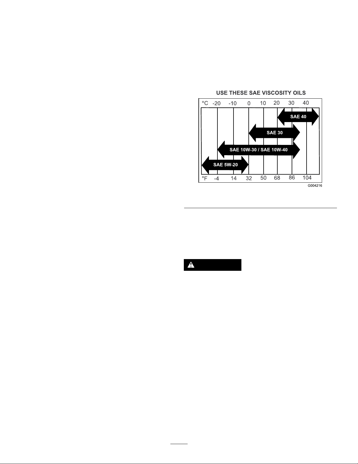
Engine-OilSpecications
OilType:Detergentoil(APIserviceSJorhigher)
EngineOilCapacity:2.1L(71oz)withthelter;
1.8L(61oz)withoutthelter
Viscosity:Refertothetablebelow.
g004216
Figure39
Note:Donotuseadamagedlter.
2.Ifyouarereplacingtheinnerlter,carefullyslide
itintothelterbody(Figure38).
3.Carefullyslidetheprimarylteroverthesafety
lter(Figure38).
Note:Ensurethattheprimarylterisfully
seatedbypushingontheouterrimwhile
installingit.
Important:Donotpressonthesoft,inside
areaofthelter.
4.Installtheair-cleanercoverwiththebreathercap
down,androtatesothattheretainingclamps
lockthecoverinplace(Figure38).
5.Closetheengineguard;refertoOpeningthe
EngineGuard(page29).
CheckingtheEngine-OilLevel
ServiceInterval:Beforeeachuseordaily
Note:Checktheoilwhentheengineiscold.
WARNING
Contactwithhotsurfacesmaycausepersonal
injury.
Keepyourhands,feet,face,clothingand
otherbodypartsawaythemuferandother
hotsurfaces.
Important:Donotoverllthecrankcasewithoil
becausedamagetotheenginemayresult.Donot
runenginewithoilbelowthelowmarkbecause
theenginemaybedamaged.
1.Parkthemachineonalevelsurface,disengage
thePTO,andengagetheparkingbrake.
2.Shutofftheengine,removethekey ,andwait
forallmovingpartstostopbeforeleavingthe
operatingposition.
3.Checktheengine-oillevelasshownin(Figure
40).
32

ChangingtheEngineOil
ServiceInterval:Aftertherst8hours
Every100hours
Note:Disposeoftheusedoilatarecyclingcenter.
g031341
1.Parkthemachinesothatthedrainsideisslightly
lowerthantheoppositesidetoassuretheoil
drainscompletely.
2.DisengagethePTO,movethemotion-control
leverstotheNEUTRAL-LOCKposition,and
engagetheparkingbrake.
3.Shutofftheengine,removethekey ,andwait
forallmovingpartstostopbeforeleavingthe
operatingposition.
4.ChangetheengineoilasshowninFigure41.
g031341
Figure40
g307458
g031447
Figure41
5.Slowlypourapproximately80%ofthespecied
oilintothellertubeandslowlyaddthe
additionaloiltobringittotheFullmark(Figure
42).
33
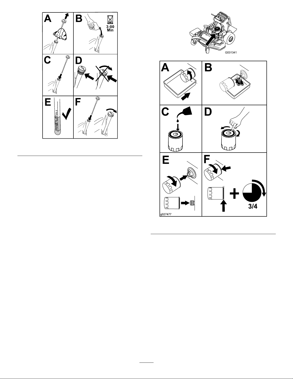
Figure42
6.Starttheengineanddrivetoaatarea.
7.Checktheoillevelagain.
ChangingtheEngine-OilFilter
g031341
g194610
ServiceInterval:Every200hours
Note:Changetheengine-oilltermorefrequently
whenoperatingconditionsareextremelydustyor
sandy.
1.Draintheoilfromtheengine;refertoChanging
theEngineOil(page33).
2.Changetheengine-oillter(Figure43).
g027477
Figure43
Note:Ensurethattheoil-ltergaskettouches
theengine,thenrotatethelteranextra3/4turn.
3.Fillthecrankcasewiththepropertypeofnew
oil;refertoEngine-OilSpecications(page32).
ServicingtheSparkPlug
ServiceInterval:Every100hours
Ensurethattheairgapbetweenthecenterandside
electrodesiscorrectbeforeinstallingthesparkplug.
Useasparkplugwrenchforremovingandinstalling
thesparkplug(s)andagappingtool/feelergaugeto
checkandadjusttheairgap.Installanewspark
plug(s)ifnecessary.
Type:NGK®BPR4ESorequivalent
Airgap:0.75mm(0.03inch)
34

RemovingtheSparkPlug
1.Parkthemachineonalevelsurface,disengage
thePTO,andengagetheparkingbrake.
2.Shutofftheengine,removethekey ,andwait
forallmovingpartstostopbeforeleavingthe
operatingposition.
3.RemovethesparkplugasshowninFigure44.
InstallingtheSparkPlug
g031449
g027661
Figure46
CheckingtheSpark
Figure44
CheckingtheSparkPlug
Important:Donotcleanthesparkplug(s).
Alwaysreplacethesparkplug(s)whenithasa
blackcoating,wornelectrodes,anoilylm,or
cracks.
Ifyouseelightbrownorgrayontheinsulator,the
engineisoperatingproperly.Ablackcoatingonthe
insulatorusuallymeanstheaircleanerisdirty .
Setthegapto0.75mm(0.03inch).
g027478
Arrester
ForMachineswithaSpark
Arrester
ServiceInterval:Every50hours
WARNING
Hotexhaust-systemcomponentsmayignite
fuelvaporsevenafteryoushutofftheengine.
Hotparticlesexhaustedduringengine
operationmayigniteammablematerials,
resultinginpersonalinjuryorproperty
damage.
Donotrefuelorruntheengineunlessthe
sparkarresterisinstalled.
1.Parkthemachineonalevelsurface,disengage
thePTO,andengagetheparkingbrake.
2.Shutofftheengine,removethekey ,andwait
forallmovingpartstostopbeforeleavingthe
operatingposition.
Figure45
g027479
3.Waitforthemufertocool.
4.Ifyouseeanybreaksinthescreenorwelds,
replacethearrester.
5.Ifthescreenisplugged,removethearrester,
shakelooseparticlesoutofthearrester,and
cleanthescreenwithawirebrush(soakthe
screeninsolventifnecessary).
6.Installthearresterontheexhaustoutlet.
35

FuelSystem
Maintenance
DrainingtheFuelTank
Youcandrainthefueltankbyremovingitandpouring
thefueloutofthellneck;refertoRemovingtheFuel
Tank(page36).Youcanalsodrainthefueltankby
usingasiphoninthefollowingprocedure.
DANGER
Incertainconditions,fuelisextremely
ammableandhighlyexplosive.Areor
explosionfromfuelcanburnyouandothers
andcandamageproperty.
RemovingtheFuelTank
1.Lowertheplatform.
2.Releasethecushion;refertoReleasingthe
CushionforRearAccess(page28).
3.Removethecrossbracket.
•Drainfuelfromthefueltankwhenthe
engineiscold.Dothisoutdoorsinanopen
area.Wipeupanyfuelthatspills.
•Neversmokewhendrainingfuel,andstay
awayfromanopename,orwhereaspark
mayignitethefuelfumes.
1.DisengagethePTO,movethemotion-control
leverstotheNEUTRAL-LOCKposition,and
engagetheparkingbrake.
2.Shutofftheengine,removethekey ,andwait
forallmovingpartstostopbeforeleavingthe
operatingposition.
3.Cleanaroundthefuelcaptopreventdebrisfrom
gettingintothefueltank(Figure47).
4.Removethefuelcap.
5.Insertasyphonpumpintothefueltank.
6.Usingthesyphonpump,drainthefuelintoafuel
container.
7.Wipeupanyspilledfuel.
Figure48
1.Fueltank
4.Removethefueltankandsetitontheoperator
platform.
2.Crossbracket
Note:Ifyouwanttomovethefueltankfurther
fromthemachine,removethefuelandvent
linesfromthetopofthetank.
g031413
1.Fuelcap
g273861
Figure47
36

ReplacingtheFuelFilter
ElectricalSystem
ServiceInterval:Every800hours/Y early(whichever
comesrst)
Donotinstalladirtylterifitisremovedfromthefuel
line.
Note:Wipeupanyspilledfuel.
1.Parkthemachineonalevelsurface,disengage
thePTO,andengagetheparkingbrake.
2.Shutofftheengine,removethekey ,andwait
forallmovingpartstostopbeforeleavingthe
operatingposition.
3.Closethefuel-shutoffvalve;refertoUsingthe
Fuel-ShutoffValve(page24).
4.ReplacethefuellterasshowninFigure49.
Maintenance
ElectricalSystemSafety
•Disconnectthebatteryorremovethespark-plug
wirebeforemakinganyrepairs.Disconnectthe
negativeterminalrstandthepositiveterminal
last.Connectthepositiveterminalrstand
negativelast.
•Chargethebatteryinanopen,well-ventilated
area,awayfromsparksandames.Unplugthe
chargerbeforeconnectingordisconnectingthe
battery.Wearprotectiveclothinganduseinsulated
tools.
ServicingtheBattery
ServiceInterval:Every100hours
Alwayskeepthebatterycleanandfullycharged.Use
apapertoweltocleanthebatterycase.Ifthebattery
terminalsarecorroded,cleanthemwithasolutionof
fourpartswaterand1partbakingsoda.Applyalight
coatingofgreasetothebatteryterminalstoprevent
corrosion.
Figure49
Voltage:12V
RemovingtheBattery
1.Parkthemachineonalevelsurface,disengage
thePTO,andengagetheparkingbrake.
2.Shutofftheengine,removethekey ,andwait
forallmovingpartstostopbeforeleavingthe
operatingposition.
3.RemovethebatteryasshowninFigure50.
g027518
37

ChargingtheBattery
WARNING
Chargingthebatteryproducesgassesthat
canexplode.
Neversmokenearthebatteryandkeepsparks
andamesawayfrombattery.
Important:Alwayskeepthebatteryfullycharged
(1.265specicgravity)topreventbatterydamage
whenthetemperatureisbelow0°C(32°F).
1.Removethebatteryfromthechassis;referto
RemovingtheBattery(page37).
2.Checktheelectrolytelevel.
3.Ensurethatthellercapsareinstalledonthe
battery.
4.Chargethebatteryfor1hourat25to30Aor6
hoursat4to6A.
5.Whenthebatteryisfullycharged,unplugthe
chargerfromtheelectricaloutlet,anddisconnect
thechargerleadsfromthebatteryposts(Figure
51).
Figure50
6.Installthebatteryontothemachineandconnect
thebatterycables;refertoInstallingtheBattery
(page39).
Note:Donotrunthemachinewiththebattery
g030988
disconnected;electricaldamagemayoccur.
Figure51
1.Positivebatterypost
2.Negativebatterypost
3.Red(+)chargerlead
4.Black(-)chargerlead
g000538
38

InstallingtheBattery
InstallthebatteryasshowninFigure52.
ServicingtheFuses
Theelectricalsystemisprotectedbyfuses.It
requiresnomaintenance.Ifafuseblows,checkthe
componentorcircuitforamalfunctionorshort.
1.Parkthemachineonalevelsurface,disengage
thePTO,andengagetheparkingbrake.
2.Shutofftheengine,removethekey ,andwait
forallmovingpartstostopbeforeleavingthe
operatingposition.
3.Releasetheoperatorcushionfromtherearof
themachine.
4.Ifyouneedtoaccessthechargefuse,remove
thefueltank;refertoRemovingtheFuelT ank
(page36).
5.Pulloutthefuseandreplaceit(Figure53).
Figure52
g301335
g030989
1.Keyswitchfuse(15A)4.Hourmeter(7.5A)
2.Accessoryport(15A)5.Chargefuse(30A)
3.Power-takeoff(PTO)fuse
(10A)
Figure53
6.Installthefueltank,ifremoved;referto
RemovingtheFuelTank(page36).
7.Installtheoperatorcushion.
39

DriveSystem
Maintenance
AdjustingtheTracking
Note:Ifyouareunabletoachieveproper
trackingbyadjustingtheleftcontrolrod,contact
yourAuthorizedServiceDealer.
6.Checkthatthemachinedoesnotcreepfrom
theneutralpositionwiththeparkbrakes
disengaged.
Ifyoupushbothmotion-controlleversforwardthe
samedistanceandthemachinepullsto1side,adjust
thetrackingasfollows.
1.Parkthemachineonalevelsurface,disengage
thePTO,andengagetheparkingbrake.
2.Shutofftheengine,removethekey ,andwait
forallmovingpartstostopbeforeleavingthe
operatingposition.
3.Releasethecushionfromtherearofthe
machine;refertoReleasingtheCushionfor
RearAccess(page28).
Note:Foreasieraccess,youcanalsoremove
thefueltank;refertoRemovingtheFuelT ank
(page36).
4.Rotatetheleftcontrolrodinquarter-turn
incrementsuntilthemachinetracksstraight
(Figure54).
Note:Ifthemachinepullstotheright,shorten
thecontrolrodbyrotatingittotheright.Ifthe
machinepullstotheleft,lengthentherodby
rotatingittotheleft.
7.Installthefueltank,ifyouremovedit.
8.Installthecushion.
CheckingtheTirePressure
ServiceInterval:Every50hours/Monthly(whichever
comesrst)
Maintaintheairpressureinthereartiresat83to97
kPa(12to14psi).
Important:Uneventirepressurecancausean
unevencut.
Note:Thefronttiresaresemi-pneumatictiresanddo
notrequireair-pressuremaintenance.
Note:Adjustonlytheleftcontrolrodtomatch
theleftwheelspeedtotherightwheelspeed.
Donotadjusttherightwheelspeed,asthis
positionstherightmotion-controlleveroutofthe
centerforthecontrolpanelneutral-lockslot.
Important:Donotrotatethecontrolrodtoo
far,asthismaycausethemachinetocreep
inneutral.
Figure54
1.Rotatelefttolengthenthe
rod.
2.Leftcontrolrod
3.Rotaterighttoshortenthe
rod.
g001055
Figure55
g031531
5.Checkforpropertracking,andadjusttherod
asnecessary.
40

AdjustingtheCaster-Pivot
ServicingtheCaster
Bearing
ServiceInterval:Every500hours/Y early(whichever
comesrst)
1.Disengagetheblade-controlswitch(PTO),move
themotioncontrolleverstotheNEUTRAL-LOCK
position,andsettheparkingbrake.
2.Shutofftheengine,removethekey ,andwait
forallmovingpartstostopbeforeleavingthe
operatingposition.
3.Removethedustcapfromthecasterandtighten
thelocknut(Figure56).
4.Tightenthelocknutuntilthespringwashersare
at,andthenbackoffa1/4turntoproperlyset
thepreloadonthebearings(Figure56).
Important:Makesurethatthespring
washersareinstalledcorrectlyasshownin
Figure56.
5.Installthedustcap(Figure56).
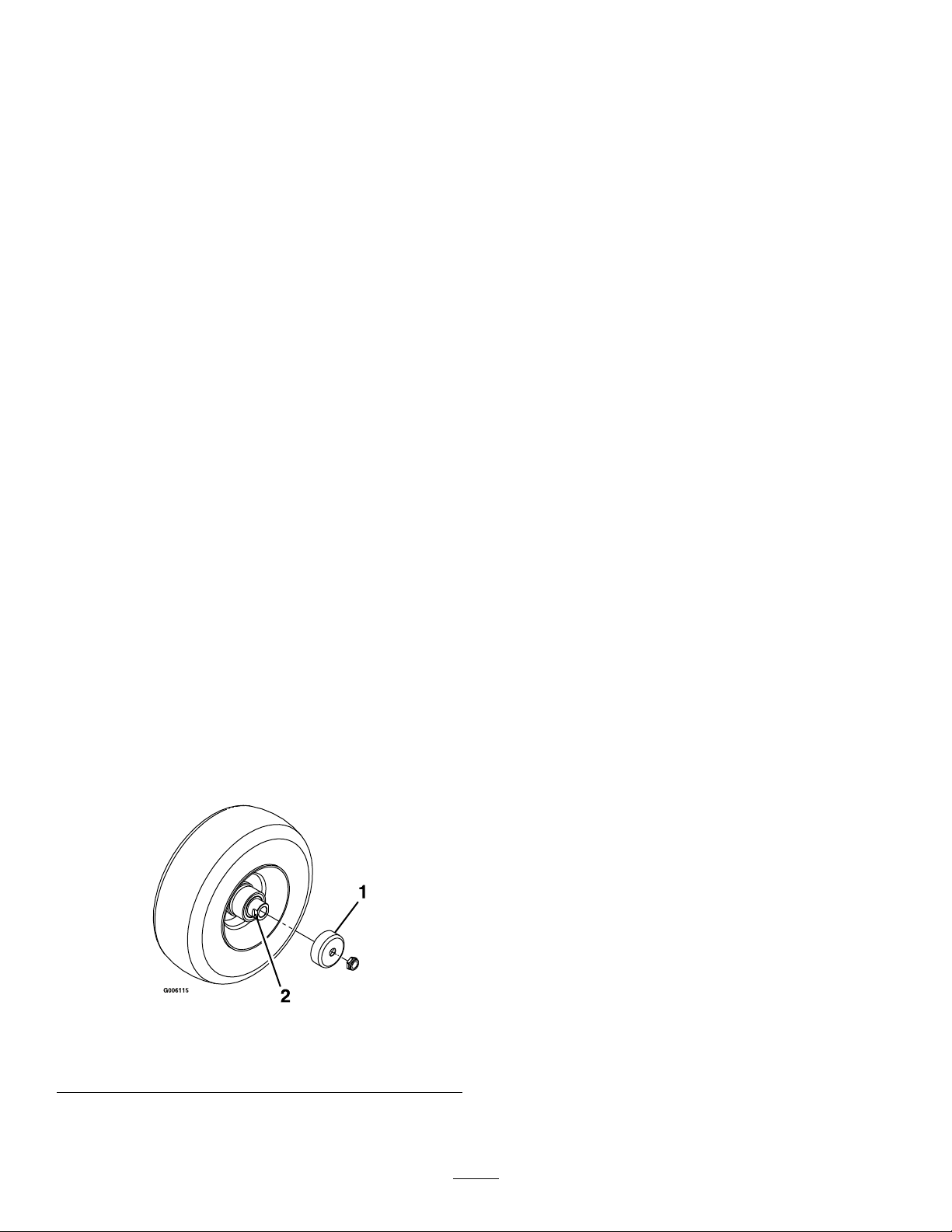
WheelsandBearings
Thecasterwheelsrotateonarollerbearingsupported
byaspannerbushing.Ifthebearingiskeptwell
lubricated,wearwillbeminimal.Failuretokeepthe
bearingwelllubricatedcausesrapidwear.Awobbly
casterwheelusuallyindicatesawornbearing.
1.Removethelocknutandwheelboltholdingthe
casterwheeltothecasterfork(Figure57).
1.Springwashers
2.Locknut
Figure56
3.Dustcap
g009453
Figure57
1.Locknut4.Rollerbearing
2.Bushing
3.Spannerbushing
2.Remove1bushing,thenpullthespanner
bushingandrollerbearingoutofthewheelhub
(Figure57).
3.Removetheotherbushingfromthewheelhub
andcleananygreaseanddirtfromthewheel
g001297
hub(Figure57).
4.Inspecttherollerbearing,bushings,spanner
bushingandtheinsideofthewheelhubforwear.
5.Casterwheel
6.Wheelbolt
Note:Replaceanydamagedorwornparts
(Figure57).
5.Place1bushingintothewheelhub(Figure57).
6.Greasetherollerbearingandspannerbushing,
andslidethemintothewheelhub(Figure57).
7.Placethesecondbushingintothewheelhub
(Figure57).
8.Installthecasterwheelintothecasterforkand
secureitwiththewheelboltandlocknut(Figure
57).
41
9.Tightenthelocknutuntilthespannerbushing
bottomsagainsttheinsideofthecasterforks
(Figure57).
4.Checktheconditionofthewire-harnessleads,
connectors,andterminals.Cleanorrepairthem
asnecessary.
10.Greasethettingonthecasterwheel.
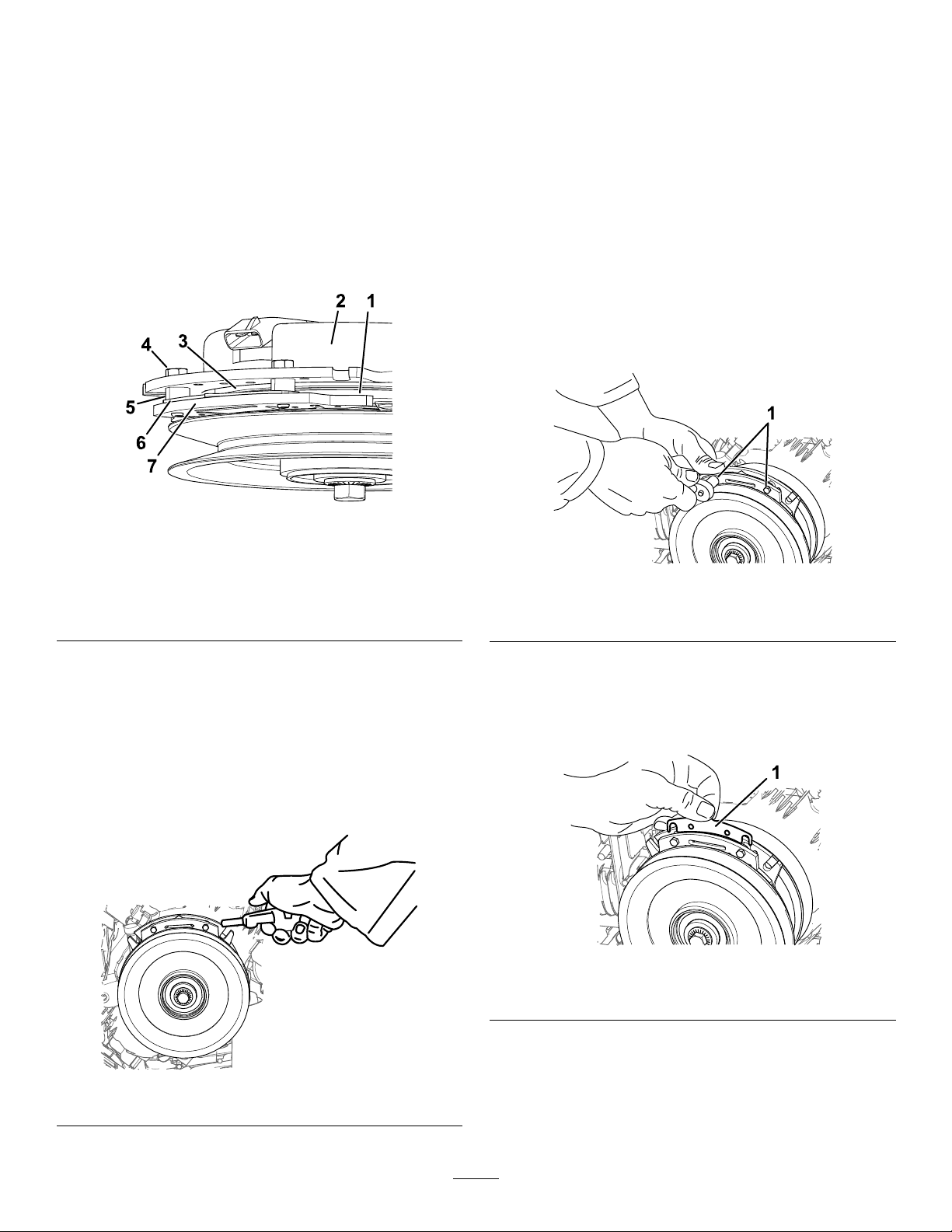
RemovingtheClutchShim
ServiceInterval:Every100hours
Whentheclutchbrakehasworntothepointwhere
theclutchnolongerengagesconsistently,youcan
removetheshimtoextendtheclutchlife(Figure58).
Figure58
1.Armature5.Brakespacer
2.Fieldshell
3.Rotor7.Brakepole
4.Brake-mountingbolt
6.Shim.
5.Verifythat12Vispresentattheclutchconnector
whentheyouengagethePTOswitch.
6.Measurethegapbetweentherotorand
armature.Ifthegapisgreaterthan1mm(0.04
inch),proceedwiththefollowingsteps:
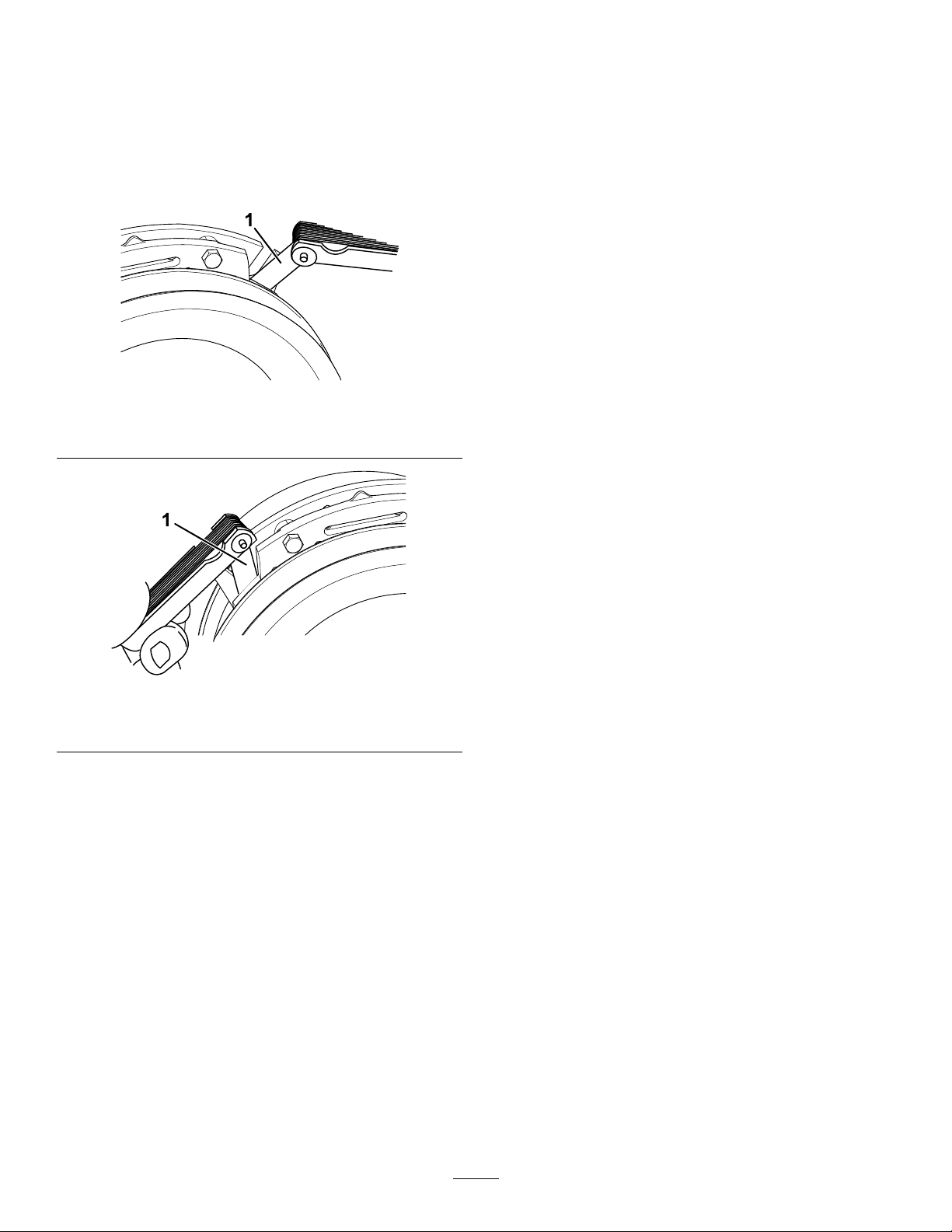
A.Loosenbothbrakemountingbolts1/2to1
fullturnasshowninFigure60.
Note:Donotremovethebrakepolefrom
theeldshell/armature.Thebrakepole
hasworntomatchthearmatureandneeds
tocontinuetomatchafteryouremovethe
shimtoensuretheproperbraketorque.
g302539
g302537
Figure60
1.Brake-mountingbolt
1.Parkthemachineonalevelsurface,disengage
thePTO,andengagetheparkingbrake.
2.Shutofftheengine,removethekey ,andwait
forallmovingpartstostopbeforeleavingthe
operatingposition.
3.Usinganaircompressor,blowoutanydebris
underthebrakepoleandaroundthebrake
spacers.
Figure59
B.Usingneedle-nosepliers,orbyhand,
removetheshim.
Note:Donotdiscardtheshimuntilyou
conrmthattheclutchfunctionsproperly.
g302538
Figure61
1.Shim
C.Usingapneumaticline,blowoutanydebris
g302534
underthebrakepoleandaroundthebrake
spacers.
D.T orqueeachbolt(M6x1)to12.3to13.7
N∙m(9.5to10.5ft-lb).
42
E.Usinga0.010inchthick-feelergauge,verify
thatagapispresentbetweentherotorand
armaturefaceonbothsidesofthebrake
poleasshowninFigure62andFigure63.
Note:Duetothewaytherotorand
armaturefaceswear(peaksandvalleys),it
issometimesdifculttomeasurethetrue
gap.
Figure62
1.Feelergauge
F.Performthefollowingsafetycheck:
i.Starttheenginefromtheoperator’s
position.
ii.Makesurethatthebladesdonot
engagewhenthePTOswitchisin
theOFFpositionandtheclutchis
disengaged.
Note:Iftheclutchdoesnot
disengage,installtheshim,andrefer
toTroubleshooting(page57).
iii.EngageanddisengagethePTO
switch10consecutivetimesto
ensurethattheclutchisfunctioning
properly.
Note:Iftheclutchdoesnotengage
g302536
properly,refertoTroubleshooting
(page57).
CheckingtheWheel-Lug
Nuts
1.Feelergauge
ServiceInterval:Aftertherst100hours—Checkthe
wheel-lugnuts.
Checkandtorquethewheel-lugnutsto115to142
N∙m(85to105ft-lb).
g302535
Figure63
•Ifthegapislessthan0.010inch,
theninstalltheshimandreferto
Troubleshooting(page57).
•Ifthegapissufcient,proceedtothe
safetycheckinstepF.
43

CoolingSystem
Maintenance
BrakeMaintenance
TestingtheParkingBrake
CleaningtheAir-Intake
Screen
ServiceInterval:Beforeeachuseordaily
Beforeeachuse,removeanybuildupofgrass,dirt,
orotherdebrisfromthecylinderandcylinder-head
coolingns,air-intakescreenontheywheelend,
andthecarburetor-governorleversandlinkage.This
helpsensureadequatecoolingoftheengineandthe
correctenginespeed,anditreducesthepossibilityof
overheatingormechanicaldamagetotheengine.
CleaningtheCooling
System
ServiceInterval:Every100hours—Checkand
cleantheenginecoolingnsand
shrouds(moreoftenindirtyordusty
conditions).
1.Parkthemachineonalevelsurface,disengage
thePTO,andengagetheparkingbrake.
2.Shutofftheengine,removethekey ,andwait
forallmovingpartstostopbeforeleavingthe
operatingposition.
ServiceInterval:Beforeeachuseordaily
Beforeeachuse,testtheparkingbrakeonbotha
levelsurfaceandslope.
Alwaysengagetheparkingbrakewhenyoustopthe
machineorleaveitunattended.Iftheparkingbrake
doesnotholdsecurely ,adjustit.
1.DisengagethePTOandengagetheparking
brake
2.Shutofftheengine,removethekey ,andwait
forallmovingpartstostopbeforeleavingthe
operatingposition.
3.Disengagetheparkingbrake.
4.Engagethebrakeleverandensurethatthe
machinedoesnotmove.
5.Adjustthebrakeifneeded.
AdjustingtheBrakes
1.Removethefueltank;refertoRemovingthe
FuelT ank(page36).
2.Loosentheboltonthecableclampontheleft
sideofthemachine.
3.Removetheair-intakescreenandfanhousing
(Figure64).
4.Cleanthedebrisandgrassfromtheengine
parts.
5.Installtheair-intakescreenandfanhousing
(Figure64).
Figure64
1.Guardandengine
air-intakescreen
2.Fanhousing
g031396
Figure65
1.Cable
2.Cableclamp
g031343
3.Pulldownonthecablesuntiltheyaretaut.
4.Tightenthenut.
5.Installthefueltank,crossbracket,andcushion.
3.Boltandnut
44
BeltMaintenance
CheckingtheBelts
ServiceInterval:Every100hours—Checkthe
mower-deckbelt(s).
Checkbeltsforcracks,frayededges,burnmarks,
wear,signsofoverheating,oranyotherdamage.
Thesignsofawornmowerbeltaresquealingwhile
thebeltisrotating,bladesslippingwhileyouare
cuttinggrass,frayedbeltedges,burnmarks,and
cracks.Replacethemowerbeltifyoudetectanyof
thesesigns.
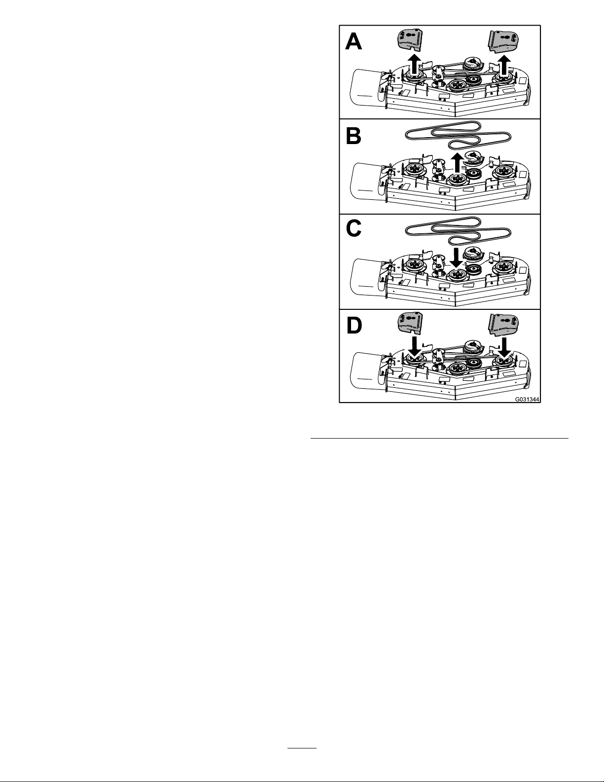
ReplacingtheMower-Deck
Belt
1.DisengagethePTOandengagetheparking
brake.
2.Shutofftheengine,removethekey ,andwait
forallmovingpartstostopbeforeleavingthe
operatingposition.
3.Opentheengineguard;refertoOpeningthe
EngineGuard(page29).
4.ReplacethebeltasshowninFigure66.
g031344
Figure66
5.Closetheengineguard.
45
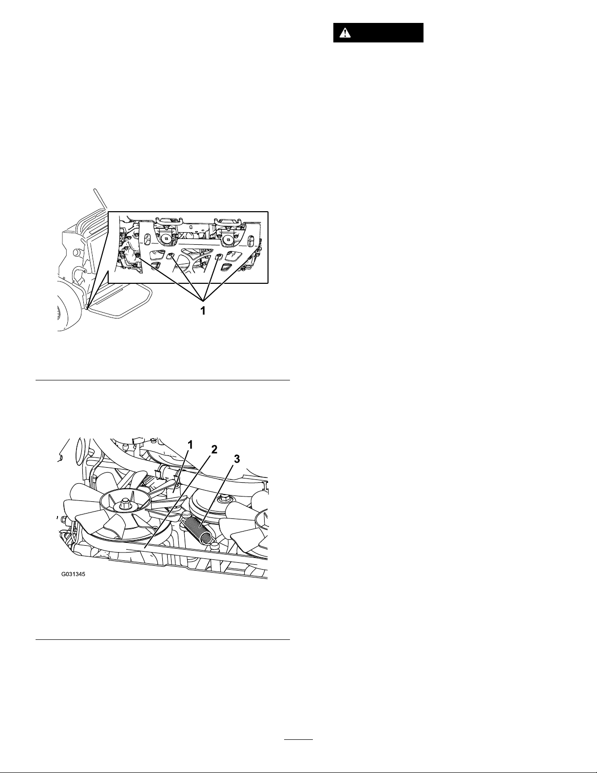
ReplacingtheTransmission
CAUTION
Belt
ServiceInterval:Every1,000hours—Replacethe
transmissionbelt.
1.Removethefueltank;refertoRemovingthe
FuelT ank(page36).
2.Removethehydraulic-reservoircap.
3.Locatethedrainplugsinthebottomofthe
transmissionandplaceadrainpanunderthe
plug(Figure67).
Figure67
Thespringisundertensionwhen
installedandcancausepersonalinjury.
Wearsafetyglassesandbecarefulwhen
removingthespring.
7.Removethedeckbeltfromtheclutchandclutch
stop(Figure66).
8.Installthenewbelt.
9.Installthetensionspringandlowerhydraulic
hose.
10.Installthedrainplugsandtorqueto22to27
N∙m(16to20ft-lb).
11.Addhydraulicuidtothelllevel.
12.Installthehydraulic-reservoircap.
13.Runthemachinefor10minutesandverifythat
thehydraulicuidisatthecorrectlevel.
g267274
1.Drainplug
4.Allowthehydraulicuidtodrainfromthe
machine.
5.Removethelowerhydraulichose(Figure68).
Figure68
1.Lowerhydraulichose3.Tensionspring
2.Transmissionbelt
g031345
6.Removethetensionspring(Figure68).
46
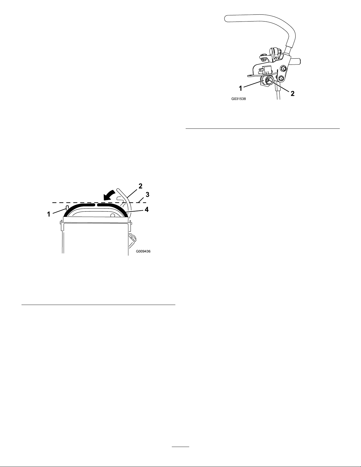
ControlsSystem
Maintenance
Adjustingthe
Motion-ControlLevers
Ifthemotion-controlleversdonotalignhorizontally ,
adjustthemotion-controllevers.
1.Parkthemachineonalevelsurface,disengage
thePTO,andengagetheparkingbrake.
2.Shutofftheengine,removethekey ,andwait
forallmovingpartstostopbeforeleavingthe
operatingposition.
3.Pushthemotion-controlleversdownoutofthe
NEUTRAL-LOCKposition(Figure69).
4.Checkiftherightmotion-controlleveraligns
horizontallywiththeleftmotion-controllever
(Figure69).
Figure69
g031538
Figure70
1.Cam
7.Adjustthecamuntilitalignswiththeleft
motion-controlleverandtightenthenutforthe
cam.
2.Nut
Note:Movingthecamclockwise(inthevertical
position)lowersthehandle;movingthecam
counterclockwise(intheverticalposition)raises
thehandle.
Important:Ensurethattheatportionofthe
camdoesnotgoaboveaverticalposition
(rightorleft);otherwiseyoumaydamagethe
switch.
8.Repeatsteps3through7fortheleft
motion-controllever.
g009436
1.Leftmotion-controllever3.Checkthehorizontal
2.Rightmotion-controllever
intheNeutral-lockposition
alignmenthere
4.Rightmotion-controllever
Note:T oadjusttherightmotion-controllever
horizontally,adjustthecam.
5.Releasethecushionfromtherearofthe
machine.
6.Loosenthenutholdingthecam(Figure70).
47

HydraulicSystem
Maintenance
HydraulicSystemSafety
•Seekimmediatemedicalattentionifuidisinjected
intoskin.Injecteduidmustbesurgicallyremoved
withinafewhoursbyadoctor.
•Ensurethatallhydraulic-uidhosesandlinesare
ingoodconditionandallhydraulicconnections
andttingsaretightbeforeapplyingpressureto
thehydraulicsystem.
•Keepyourbodyandhandsawayfrompinhole
leaksornozzlesthatejecthigh-pressurehydraulic
uid.
•Usecardboardorpapertondhydraulicleaks.
•Safelyrelieveallpressureinthehydraulicsystem
beforeperforminganyworkonthehydraulic
system.
HydraulicSystem
Specications
HydraulicFluidT ype:Toro
hydraulicuid
HydraulicSystemFluidCapacity:4.7L(159oz)
Important:Usetheuidspecied.Otheruids
coulddamagethesystem.
®
HYPR-OIL
CheckingtheHydraulic
™
500
Figure71
1.Hydraulic-tankcap
5.Removethecapfromthellerneck(Figure71).
Note:Lookinsidetochecktheuidlevelin
thereservoir.
6.Adduidtothereservoiruntilitreachesthe
reachestheminimumcoldlllevel.
7.Installthecaponthellerneck.
2.Colduidlevel
ReplacingtheHydraulic
FluidandFilters
ServiceInterval:Aftertherst50hours
Every500hours/Yearly(whichevercomes
rst)—Changethehydraulicltersandhydraulic
uid.
g301336
Fluid
ServiceInterval:Aftertherst8hours
Every50hours
Note:Checkthehydraulic-uidlevelwhentheuid
iscold.
1.Parkthemachineonalevelsurface,disengage
thePTO,andengagetheparkingbrake.
2.Shutofftheengine,removethekey ,andwait
forallmovingpartstostopbeforeleavingthe
operatingposition.
3.Waitforthemachinetocool.
4.Cleantheareaaroundthecapandthellerneck
ofthehydraulictank(Figure71).
Changethehydraulicuidmorefrequentlyinsevere
conditionsorinahotoperatingclimate.Contact
yourAuthorizedServiceDealerforahydraulickitto
replacethehydrauliclters.
WARNING
Hothydraulicuidcancausesevereburns.
Allowthehydraulicuidtocoolbefore
performinganymaintenanceonthehydraulic
system.
1.Parkthemachineonalevelsurface,disengage
thePTO,andengagetheparkingbrake.
2.Shutofftheengine,removethekey ,andwait
forallmovingpartstostopbeforeleavingthe
operatingposition.
3.Removethefueltank;refertoRemovingthe
FuelT ank(page36).
48

4.Removethehydraulic-reservoircap.
5.Locatethedrainpluginthebottomofeach
transmissionandplaceadrainpanunderthe
plugs(Figure72).
Figure72
Important:Usetheuidspeciedin
HydraulicSystemSpecications(page48)or
equivalent.Otheruidscouldcausesystem
damage.
Important:Monitorthelevelofuidinthe
hydraulictanksothatyoudonotoverllit.
13.Tightentheventplugs.
14.Installthehydraulic-tankcap.
15.Installthefueltank.
16.Starttheengineandletitrunforabout2minutes
topurgeairfromthesystem.
17.Shutofftheengineandcheckforleaks.
Note:If1orbothwheelsdonotdrive,referto
g268090
BleedingtheHydraulicSystem(page49).
1.Drainplug
6.Removethedrainplugs.
7.Allowthehydraulicuidtofullydrainfromthe
machine.
8.Removethehydraulicltercapandlterfrom
eachtransmission.
9.Installnewhydrauliclterswiththespringside
facingoutandinstalltheltercaps.
10.Installthedrainplugsandtorqueto22to27
N∙m(16to20ft-lb).
11.Loosentheventplugineachtransmissionso
thatitislooseandwobbles(Figure73).
2.Hydrauliclter
Note:Thisallowsairtoescapethehydraulic
systemasyouaddhydraulicuid.
BleedingtheHydraulic
System
Thetractionsystemisself-bleeding,however,itmay
benecessarytobleedthesystemifuidischanged
orafterworkisperformedonthesystem.
1.Parkthemachineonalevelsurface,disengage
thePTO,andengagetheparkingbrake.
2.Shutofftheengine,removethekey ,andwait
forallmovingpartstostopbeforeleavingthe
operatingposition.
3.Raisetherearofthemachineontojackstands
highenoughtoraisethedrivewheelsoffthe
ground.
4.Starttheengineandmovethethrottlecontrolto
theidleposition.
Note:Ifthedrivewheeldoesnotrotate,assist
thepurgingofthesystembycarefullyrotating
thetireintheforwarddirection.
5.Checkthehydraulicuidlevelasitdrops,and
adduidasrequiredtomaintaintheproperlevel.
Figure73
Lefttransmissionshown
1.Ventplug
12.Slowlyadduidtothehydraulictankuntilit
startstocomeout1oftheventplugs.
6.Repeatthisprocedurefortheoppositewheel.
g031544
49

MowerDeck
Maintenance
BladeSafety
Awornordamagedbladecanbreak,andapieceof
thebladecouldbethrowntowardyouorbystanders,
resultinginseriouspersonalinjuryordeath.
•Inspectthebladesperiodicallyforwearordamage.
•Usecarewhencheckingtheblades.Wrapthe
bladesorweargloves,andusecautionwhen
servicingtheblades.Onlyreplaceorsharpenthe
blades;neverstraightenorweldthem.
•Alwaysinspectthemachinetoensurethatthe
bladesandbladeboltsarenotwornordamaged.
Replacewornordamagedbladesandboltsinsets
topreservebalance.
•Onmulti-bladedmachines,takecareasrotating1
bladecancauseotherbladestorotate.
g006530
Figure74
1.Cuttingedge3.Wear/slotforming
2.Curvedarea4.Crack
CheckingforBentBlades
1.Rotatethebladesuntiltheendsfaceforward
andbackward.
2.Measurefromalevelsurfacetothecutting
edge,positionA,oftheblades(Figure75).
ServicingtheCutting
Blades
Toensureasuperiorqualityofcut,keeptheblades
sharp.Forconvenientsharpeningandreplacement,
keepextrabladesonhand.
BeforeInspectingorServicingthe
Blades
1.Parkthemachineonalevelsurface,disengage
thePTO,andengagetheparkingbrake.
2.Shutofftheengine,removethekey ,and
disconnectthespark-plugwiresfromthespark
plugs.
InspectingtheBlades
ServiceInterval:Beforeeachuseordaily
1.Inspectthecuttingedges(Figure74).
2.Iftheedgesarenotsharporhavenicks,remove
andsharpentheblade;refertoSharpeningthe
Blades(page51).
3.Inspecttheblades,especiallyinthecurvedarea.
4.Ifyounoticeanycracks,wear,oraslotforming
inthisarea,immediatelyinstallanewblade
(Figure74).
Figure75
1.Measureherefromblade
tohardsurface
3.Rotatetheoppositeendsofthebladesforward.
4.Measurefromalevelsurfacetothecuttingedge
ofthebladesatthesamepositionasinstep2
above.
2.PositionA
Note:Thedifferencebetweenthedimensions
obtainedinsteps2and3mustnotexceed3mm
(1/8inch).
Note:Ifthisdimensionexceeds3mm
(1/8inch),replacetheblade.
g000975
50

WARNING
Abladethatisbentordamagedcould
breakapartandcouldcriticallyinjure
youorbystanders.
•Alwaysreplaceabentordamaged
bladewithanewblade.
•Donotleorcreatesharpnotchesin
theedgesorsurfacesoftheblade.
RemovingtheBlades
Replacethebladesiftheyhitasolidobject,orifthe
bladeisoutofbalanceorbent.
1.Placeawrenchontheatofthespindleshaftor
holdthebladeendusingaragorthicklypadded
glove.
2.Removethebladebolt,bushing,andbladefrom
thespindleshaft(Figure76).
g000552
Figure77
1.Sharpenatoriginalangle.
2.Checkthebalanceofthebladebyputtingitona
bladebalancer(Figure78).
Note:Ifthebladestaysinahorizontalposition,
thebladeisbalancedandcanbeused.
Note:Ifthebladeisnotbalanced,lesome
metalofftheendofthesailareaonly(Figure77).
g000553
Figure78
1.Blade2.Balancer
Figure76
1.Sailareaoftheblade
2.Blade5.Bladebolt
3.Flatofthespindleshaft
4.Bushing
SharpeningtheBlades
3.Repeatthisprocedureuntilthebladeis
balanced.
InstallingtheBlades
1.Installthebushingthroughthebladewiththe
bushingangeonthebottom(grass)sideofthe
blade(Figure79).
g295816
g255205
Figure79
1.Bushing
2.Installthebushing/bladeassemblyintothe
spindleshaft(Figure80).
1.Usealetosharpenthecuttingedgeatboth
endsoftheblade(Figure77).
Note:Maintaintheoriginalangle.
Note:Thebladeretainsitsbalanceifthesame
amountofmaterialisremovedfrombothcutting
edges.
51

Figure80
1.Topspindlenut3.Bladebolt
2.Flatofthespindleshaft
3.Applycopper-basedlubricantorgreasetothe
threadsofthebladeboltasneededtoprevent
seizing.Installthebladeboltnger-tight.
4.Placeawrenchontheatofthespindleshaft
andtorquethebladeboltto75to81N∙m(55
to60ft-lb).
CheckingtheMowerDeck
Side-to-SideHeight
1.Adjusttherear-tirepressure.
2.Ensurethatthebladesarenotbent;referto
CheckingforBentBlades(page50).
3.Positionthebladessidetoside.
4.MeasureattheBandClocationsfromalevel
surfacetothecuttingedgeofbladetips(Figure
81).
g298850
g006888
Figure81
1.Measurefromalevel
surface
2.Measurethebladeat
pointsBandC
LevelingtheMowerDeck
PreparingtheMachine
Ensurethatthemowerdeckislevelanytimeyou
installthemowerdeckorwhenyouseeanuneven
cutonyourlawn.
Levelthemowerdecksidetosidebeforeadjusting
thefront-to-rearslope.
1.Parkthemachineonalevelsurface,disengage
thePTO,andengagetheparkingbrake.
2.Shutofftheengine,removethekey ,and
disconnectthespark-plugwiresfromthespark
plugs.
3.Checkthetirepressureofbothdrivetires;refer
toCheckingtheTirePressure(page40).
4.Checkthemowerdeckforbentblades;remove
andreplaceanybentblades;refertoServicing
theCuttingBlades(page50).
5.Lowerthemowerdecktothe76mm(3inch)
height-of-cutposition.
5.ThedifferencebetweenmeasurementsBandC
shouldbenomorethan6mm(1/4inch).
Note:Ifitisnotcorrect,refertoLevelingthe
MowerDeckfromSidetoSide(page52).
LevelingtheMowerDeckfrom
SidetoSide
1.Loosenthesidenutandjamnutintheyokes
youwanttoadjust(Figure82).
52

Figure82
1.Topbolt
2.Jamnut5.Adjusttheseyokesto
3.Yoke6.Adjusttheseyokesto
4.Sidenut
adjusttherightsideofthe
mowerdeck.
adjusttheleftsideofthe
mowerdeck.
2.Rotatethetopboltoftheyokestoadjustthe
heightofthemowerdeck(Figure82).
Note:Rotatetheboltsclockwisetoraisethe
deck;rotatetheboltcounterclockwisetolowerit.
3.Tightenthejamnutsandsidebolts.
4.Checktheside-to-sideheight;refertoChecking
theMowerDeckSide-to-SideHeight(page52).
CheckingtheMowerDeck
Front-to-RearPitch
1.Adjustthetirepressureinthereartirestothe
correctspecications.
g031415
g001041
Figure83
1.Measurethebladeat
pointsAandB
2.Measurefromalevel
surface
4.Ifthefront-to-rearpitchisnotcorrect,referto
LevelingtheMowerDeckfromFronttoRear
(page53).
LevelingtheMowerDeckfrom
FronttoRear
1.Loosenthejamnutandsideboltintheyokes
thatyouwanttoadjust(Figure84).
2.Position1bladefront-to-rear.MeasureatAand
Blocationsfromalevelsurfacetothecutting
edgeofthebladetips(Figure83).
Note:Themowerbladeshouldbe6mm(1/4
inch)lowerinfrontatAthanintherearatB.
3.Rotatethebladesandrepeatforotherblades.
Figure84
1.Topbolt
2.Jamnut5.Adjusttheseyokesto
3.Yoke6.Adjusttheseyokesto
4.Sidenut
adjustthefrontsideofthe
mowerdeck.
adjusttherearsideofthe
mowerdeck.
2.Rotatethetopboltoftheyokestoadjustthe
heightofthemowerdeck(Figure84).
53
g031416

Note:Rotatetheboltclockwisetoraisethe
deck;rotatetheboltcounterclockwisetolowerit.
3.Tightenthejamnutsandsidebolts.
AdjustingtheDeck-Lift
Spring
4.Checkthefront-to-rearpitch;refertoChecking
theMowerDeckFront-to-RearPitch(page53).
MatchingtheHeight-of-Cut
1.Checkthereartirepressure.
2.Settheheight-of-cuttothe76mm(3inch)
position;refertoAdjustingtheHeight-of-Cut
(page21).
3.Withthemachineonlevelsurface,position1
bladefront-to-rear.
4.MeasureatA,andfromalevelsurfacetothe
cuttingedgeofthebladetips(Figure85).
Note:Themeasurementshouldbe76mm(3
inches).
Note:Adjustingthecompressionspringaltershow
muchthedeckoatsandtheamountofeffortneeded
toliftthedeckwhenusingtheheight-of-cutlever.
•Morespringextensionreducestheleverliftforce
requiredandcausesthedecktooatmore.
•Lessspringextensionincreasestheleverliftforce
requiredandcausesthedecktooatless.
1.Raisetheheight-of-cutleverandlockitintothe
transportposition.
2.Checkthedistancebetweenthespringnut
andtherearsideoftheweldedmountbracket
(Figure86).
3.Ensurethatthelengthisbetween47to50mm
(1.8to2inches)asshowninFigure86.
4.Ifneeded,adjustthedistancebyadjustingthe
boltonthefrontofthemountbracket(Figure86).
Figure85
1.Measurefromalevel
surface
2.Measurethebladeatpoint
A
5.Ifthemeasurementisnotcorrect,locatethe
front2yokesonthemachine(Figure84).
6.Loosenthesideboltandjamnutoftheyokes.
7.Adjustthetopboltoftheyokesuntiltheblade
tipsmatch76mm(3inches).
8.Tightenthejamnutsandsidebolts.
g000975
g301337
Figure86
1.Deck-liftspring
2.Springnut
3.Rearsideofthemount
bracket
4.Adjustmentbolt
5.Lengthisbetween47to
50mm(1.8to2inches).
5.Repeatthisprocedurefortheoppositedeck-lift
spring.
54

ReplacingtheGrass
Deector
WARNING
Anuncovereddischargeopeningcouldallow
themachinetothrowobjectstowardyouor
bystanders,resultinginseriousinjury.Also,
contactwiththebladecouldoccur.
Donotoperatethemachineunlessyouinstall
acoverplate,amulchplate,grassdeector,
orbagger.
1.Removethelocknut,bolt,spring,andspacer
holdingthedeectortothepivotbrackets
(Figure87).
Cleaning
CleaningundertheMower
Deck
ServiceInterval:Beforeeachuseordaily
Beforeeachuseordaily
Removethegrassbuildupunderthemowerdaily.
1.Parkthemachineonalevelsurface,disengage
thePTO,movethemotion-controlleverstothe
NEUTRAL-LOCKposition,andengagetheparking
brake.
2.Shutofftheengine,removethekey ,andwait
forallmovingpartstostopbeforeleavingthe
operatingposition.
3.Raisethefrontofthemachineandusejack
standstosupportthemower.
DisposingofWaste
Figure87
1.Bolt
2.Spacer6.Grassdeector
3.Locknut
4.Spring
2.Removethedamagedorworngrassdeector.
3.Placethespacerandthespringontothegrass
deector.
4.Place1J-hookendofthespringbehindthe
deckedge.
5.Spring(installed)
7.J-hookendofthespring
Note:Makesurethat1J-hookendofspringis
installedbehinddeckedgebeforeinstallingthe
boltasshowninFigure87.
Engineoil,batteries,hydraulicuid,andengine
coolantarepollutantstotheenvironment.Disposeof
theseaccordingtoyourstateandlocalregulations.
g015594
5.Installtheboltandthenut.
6.Place1J-hookendofthespringaroundthe
grassdeector(Figure87).
Important:Thegrassdeectormustbeable
torotate.Liftthedeectoruptothefullopen
position,andensurethatitrotatesintothe
full-downposition.
55

Storage
E.Disposeoffuelproperly;recycleitaccording
tolocalregulations.
StorageSafety
•Alwaysshutoffthemachine,removetheignition
key,waitforallmovingpartstostop,andallow
themachinetocoolbeforeadjusting,servicing,
cleaning,orstoringit.
•Lettheenginecoolbeforestoringthemachine.
•Donotstorethemachineorfuelnearamesor
drainthefuelindoors.
CleaningandStorage
1.Disengagethepowertakeoff(PTO),engagethe
parkingbrake,shutofftheengine,andremove
thekey.
2.Removegrassclippings,dirt,andgrimefromthe
externalpartsoftheentiremachine,especially
theengine.
Important:Youcanwashthemachine
withamilddetergentandwater.Donot
pressure-washthemachine.Avoidexcessive
useofwater,especiallynearthedrivesystem
andengine.Pressure-washingcanforcedirt
andwaterintocriticalparts,suchasspindle
bearingsandelectricalswitches.
3.Cleananydirtandchafffromtheoutsideofthe
enginecylinder-headnsandblowerhousing.
4.Checkthebrake;refertoTestingtheParking
Brake(page44).
5.Servicetheaircleaner;refertoServicingtheAir
Cleaner(page31).
6.Greasethemachine;refertoGreasingthe
Machine(page29).
7.Changetheengineoil;refertoServicingthe
EngineOil(page32).
8.Checkthetirepressure;refertoCheckingthe
TirePressure(page40).
9.Forlong-termstorage,dothefollowing:
A.Addfuelstabilizer/conditionertothefuelin
thetankasdirectedbythefuelstabilizer
manufacturer.
B.Runtheenginetodistributetheconditioned
fuelthroughthefuelsystemfor5minutes.
C.Shutofftheengine,allowittocool,and
drainthefueltank;refertoDrainingthe
FuelT ank(page36),oroperatetheengine
untilitshutsoff.
D.Starttheengineandallowittorununtilit
shutsoff.Repeatwiththechokeengaged(if
applicable)untiltheenginedoesnotstart.
Important:Donotstorefuelcontaining
stabilizer/conditionerlongerthan
thedurationrecommendedbythe
fuel-stabilizermanufacturer.
10.Removethesparkplug(s)andcheckits
condition;refertoServicingtheSparkPlug
(page34).
11.Withthesparkplug(s)removedfromtheengine,
pour15ml(2tablespoons)ofengineoilintothe
spark-plughole,andusethestartertocrankthe
engineanddistributetheoilinsidethecylinder.
12.Installthesparkplug(s)butdonotconnectthe
wiretothesparkplug(s).
13.Checkandtightenallfasteners.Repairor
replaceanypartthatisdamagedormissing.
14.Paintallscratchedorbaremetalsurfaceswith
paintfromanAuthorizedServiceDealer.
15.Storethemachineinaclean,dry ,garageor
storagearea.Removethekeyfromtheswitch
andstoreitinamemorableplace.Coverthe
machinetoprotectitandkeepitclean.
56

Troubleshooting
Problem
Theenginedoesnotstart,startshard,or
failstokeeprunning.
Theenginelosespower.
PossibleCauseCorrectiveAction
1.Thefueltankisemptyortheshutoff
valveisclosed.
2.Aspark-plugwireislooseor
disconnected.
3.Asparkplugispitted,fouled,orthe
gapisincorrect.
4.Theaircleanerisdirty.
5.Dirtisinthefuellter.5.Replacethefuellter.
6.Dirt,water,orstalefuelisinthefuel
system.
7.Thegapbetweenthesafety-interlock
switchesisnotcorrect.
1.Theengineloadisexcessive.1.Reducethegroundspeed.
2.Theaircleanerisdirty.
3.Theoillevelinthecrankcaseislow.3.Addoiltothecrankcase.
4.Thecoolingnsandairpassages
undertheengineblowerhousingare
plugged.
5.Asparkplugispitted,fouled,orthe
gapisincorrect.
6.Theventholeinthefuelcapisplugged.6.Cleanorreplacethefuelcap.
7.Dirtisinthefuellter.7.Replacethefuellter.
8.Dirt,water,orstalefuelisinthefuel
system.
1.Fillthefueltankwithfuelandopenthe
valve
2.Installthewireonsparkplug.
3.Installanew,correctlygappedspark
plug.
4.Servicetheair-cleanerelement.
6.ContactanAuthorizedServiceDealer.
7.ContactanAuthorizedServiceDealer.
2.Servicetheair-cleanerelement.
4.Removetheobstructionfromthe
coolingnsandairpassages.
5.Installanew,correctlygappedspark
plug.
8.ContactanAuthorizedServiceDealer.
Theengineoverheats.
Themachinedoesnotdrive.
Thereisabnormalvibration.
1.Theengineloadisexcessive.1.Reducethegroundspeed.
2.Theoillevelinthecrankcaseislow.2.Addoiltothecrankcase.
3.Thecoolingnsandairpassages
undertheengineblowerhousingare
plugged.
1.Thehydraulic-uidreservoirislow.1.Addhydraulicuidtothereservoir.
2.Airisinthehydraulicsystem.2.Bleedtheairoutthehydraulicsystem.
3.Apump-drivebeltslips.3.Replacethepump-drivebelt.
4.Apump-drivebeltidlerspringis
missing.
5.Thepump-bypassvalvesareopen.5.Tightenthebypassvalves.T orqueto
1.Cuttingblade(s)is/arebentor
unbalanced.
2.Ablade-mountingboltisloose.2.Tightentheblade-mountingbolt.
3.Theengine-mountingboltsareloose.3.Tightentheengine-mountingbolts.
4.Anenginepulley,idlerpulley,orblade
pulleyisloose.
5.Anenginepulleyisdamaged.
6.Abladespindleisbent.
3.Removetheobstructionfromthe
coolingnsandairpassages.
4.Replacethepump-drivebeltidler
spring.
12to15N∙m(9to11ft-lb).
1.Installnewcuttingblade(s).
4.Tightentheappropriatepulley.
5.
ContactanAuthorizedServiceDealer.
6.ContactanAuthorizedServiceDealer.
57

Problem
PossibleCauseCorrectiveAction
Thecuttingheightisuneven.
Thebladesdonotrotate.
1.Blade(s)arenotsharp.1.Sharpentheblade(s).
2.Cuttingblade(s)is/arebent.2.Installnewcuttingblade(s).
3.Themowerdeckisnotlevel.3.Levelthemowerdeckside-to-side
4.Themowerdeckpitchiswrong.
5.Theundersideofmowerdeckisdirty.5.Cleantheundersideofthemower
6.Thetirepressureisnotcorrect.6.Adjustthetirepressure.
7.Abladespindleisbent.
1.Apump-drivebeltisworn,looseor
broken.
2.Apump-drivebeltisoffpulley.
3.Amower-deckbeltisworn,looseor
broken.
4.Amower-deckbeltisoffthepulley.
5.Anidlerspringisbrokenormissing.5.Replacethespring.
6.Theelectricclutchisoutofadjustment.
7.Theclutchconnectororwireis
damaged.
8.Theelectricclutchisdamaged.
9.Thesafety-interlocksystemprevents
bladerotation.
10.ThePTOswitchisfaulty.10.ContactanAuthorizedServiceDealer .
position.
4.Adjustthefront-to-rearpitch.
deck.
7.ContactanAuthorizedServiceDealer.
1.Checkthebelttension.
2.Installthedrivebeltandcheckthe
adjustingshaftsandbeltguidesforthe
correctposition.
3.Installthenewdeckbelt.
4.Installthedeckpulleyandcheckthe
idlerpulley,idlerarmandspringforthe
correctpositionandfunction.
6.Adjusttheclutchairgap.
7.ContactanAuthorizedServiceDealer.
8.ContactanAuthorizedServiceDealer.
9.ContactanAuthorizedServiceDealer.
Theclutchdoesnotengage.
1.Thefuseisblown.
2.Thereislowvoltagesupplyatthe
clutch.
3.Thecoilisdamaged.3.Replacetheclutch.
4.Thereisinadequatecurrentsupply.4.Repairorreplacetheclutchlead
5.Therotor/armatureairgapistoolarge.
1.Replacethefuse.Checkthecoil
resistance,batterycharge,charging
system,andwiringconnections,and
replacecomponentsifnecessary.
2.Checkthecoilresistance,battery
charge,chargingsystem,andwiring
connectionsandreplacepartsif
necessary.
wireorelectricalsystem.Cleanthe
connectorcontacts.
5.Removetheshimorreplacetheclutch.
58
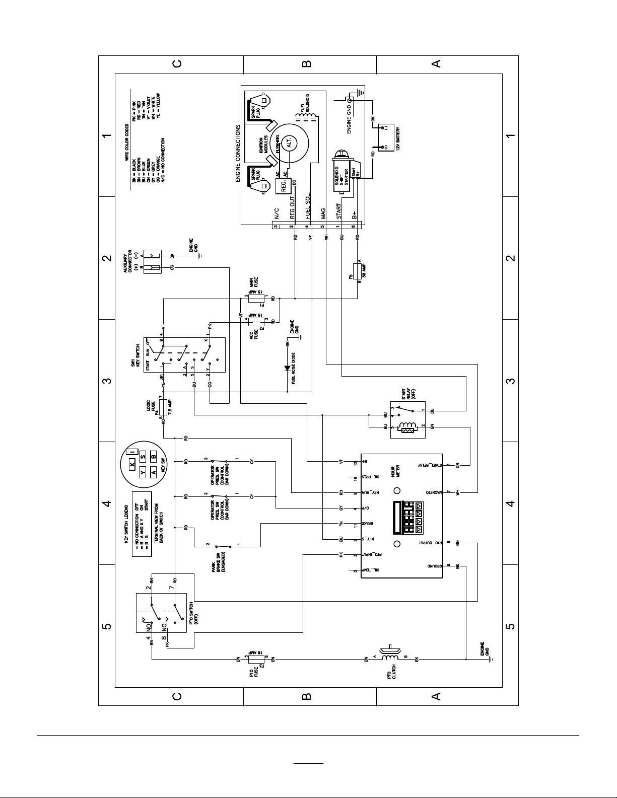
Schematics
ElectricalSchematic—140-1878(Rev.A)
59
g302050

CaliforniaProposition65WarningInformation
Whatisthiswarning?
Youmayseeaproductforsalethathasawarninglabellikethefollowing:
WARNING:CancerandReproductiveHarm—www.p65Warnings.ca.gov.
WhatisProp65?
Prop65appliestoanycompanyoperatinginCalifornia,sellingproductsinCalifornia,ormanufacturingproductsthatmaybesoldinorbroughtinto
California.ItmandatesthattheGovernorofCaliforniamaintainandpublishalistofchemicalsknowntocausecancer,birthdefects,and/orother
reproductiveharm.Thelist,whichisupdatedannually,includeshundredsofchemicalsfoundinmanyeverydayitems.ThepurposeofProp65isto
informthepublicaboutexposuretothesechemicals.
Prop65doesnotbanthesaleofproductscontainingthesechemicalsbutinsteadrequireswarningsonanyproduct,productpackaging,orliteraturewith
theproduct.Moreover,aProp65warningdoesnotmeanthataproductisinviolationofanyproductsafetystandardsorrequirements.Infact,the
CaliforniagovernmenthasclariedthataProp65warning“isnotthesameasaregulatorydecisionthataproductis‘safe’or‘unsafe.’”Manyofthese
chemicalshavebeenusedineverydayproductsforyearswithoutdocumentedharm.Formoreinformation,gotohttps://oag.ca.gov/prop65/faqs-view-all
AProp65warningmeansthatacompanyhaseither(1)evaluatedtheexposureandhasconcludedthatitexceedsthe“nosignicantrisklevel”;or(2)
haschosentoprovideawarningbasedonitsunderstandingaboutthepresenceofalistedchemicalwithoutattemptingtoevaluatetheexposure.
Doesthislawapplyeverywhere?
Prop65warningsarerequiredunderCalifornialawonly .ThesewarningsareseenthroughoutCaliforniainawiderangeofsettings,includingbutnot
limitedtorestaurants,grocerystores,hotels,schools,andhospitals,andonawidevarietyofproducts.Additionally ,someonlineandmailorder
retailersprovideProp65warningsontheirwebsitesorincatalogs.
.
HowdotheCaliforniawarningscomparetofederallimits?
Prop65standardsareoftenmorestringentthanfederalandinternationalstandards.TherearevarioussubstancesthatrequireaProp65warning
atlevelsthatarefarlowerthanfederalactionlimits.Forexample,theProp65standardforwarningsforleadis0.5μg/day,whichiswellbelow
thefederalandinternationalstandards.
Whydon’tallsimilarproductscarrythewarning?
•ProductssoldinCaliforniarequireProp65labellingwhilesimilarproductssoldelsewheredonot.
•AcompanyinvolvedinaProp65lawsuitreachingasettlementmayberequiredtouseProp65warningsforitsproducts,butothercompanies
makingsimilarproductsmayhavenosuchrequirement.
•TheenforcementofProp65isinconsistent.
•CompaniesmayelectnottoprovidewarningsbecausetheyconcludethattheyarenotrequiredtodosounderProp65;alackofwarningsfora
productdoesnotmeanthattheproductisfreeoflistedchemicalsatsimilarlevels.
WhydoesToroincludethiswarning?
Torohaschosentoprovideconsumerswithasmuchinformationaspossiblesothattheycanmakeinformeddecisionsabouttheproductstheybuyand
use.T oroprovideswarningsincertaincasesbasedonitsknowledgeofthepresenceofoneormorelistedchemicalswithoutevaluatingthelevelof
exposure,asnotallthelistedchemicalsprovideexposurelimitrequirements.WhiletheexposurefromT oroproductsmaybenegligibleorwellwithinthe
“nosignicantrisk”range,outofanabundanceofcaution,T orohaselectedtoprovidetheProp65warnings.Moreover ,ifT orodoesnotprovidethese
warnings,itcouldbesuedbytheStateofCaliforniaorbyprivatepartiesseekingtoenforceProp65andsubjecttosubstantialpenalties.
RevA
 Loading...