

Page 1

Wheel Horse Lawn Tractor
For T ractors with 32 and 38 Mowers
Loose Parts
Note: Use the chart below to verify that all parts have been shipped.
Description Qty. Use
Form No. 3328-648
Setup Instructions
Front wheels
Shim washers (as required)
Flat washers
Cotter pins
Hub caps
Steering wheel
Spirol pin
Seat
Knob
Flat washer
Wire clip (on seat pan)
Bolts—1/4-20 x 3/4 in.
Wing nuts
Spring hook 1 Installing the lift assist spring
Wheels
Wheel bolts
Locknuts—5/16 in.
2
2
2
2
2
1
1
1
1
1
1
2
2
2
2
2
Installing the front wheels
Installing the steering wheel
Installing the seat
Installing the battery cables
Installing the anti-scalp wheels
Keys 2 Using in the ignition and Key Choice switches
Operator’s Manual
Certificate of Conformance
Noise certificate
Registration Card 1 Filling out and mailing the card to Toro
2002 by The Toro Company
8111 Lyndale Avenue South
Bloomington, MN 55420-1196
1
1
1
1
Reading before operating the tractor
All Rights Reserved
Printed in the USA
Page 2
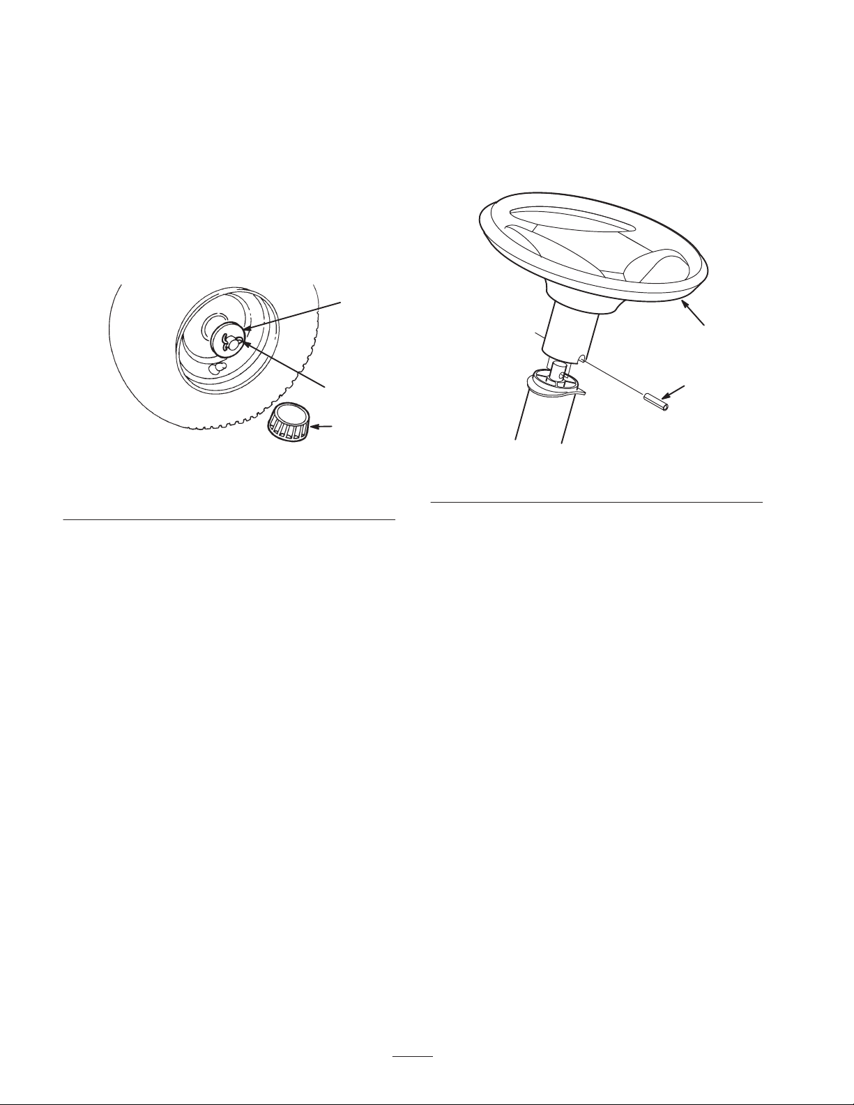
Installing the Front Wheels
Installing the Steering Wheel
Note: If the wheels are already installed, refer to
Checking the Tire Pressure below.
1. Install the shim washers onto the axle.
2. Install the wheel onto the axle with the valve stem
facing out.
3. Slide the flat washer onto the axle.
4. Insert the cotter pin through the axle and bend the ends
of the pin apart (Fig. 1).
1
2
3
m-1904
Figure 1
1. Flat washer
2. Cotter pin
3. Hub cap
1. Move the front wheels so that they face straight ahead.
2. Slide the steering wheel over the steering shaft and
line up the hole in the steering wheel with the hole in
the shaft (Fig. 2).
1
2
m-1905
Figure 2
1. Steering wheel 2. Spirol pin
Note: If the cotter pin does not fit, remove the shim
washer(s) as needed.
5. Push the hub cap (Fig. 1) onto the end of the axle.
6. Repeat steps 1 through 5 on the opposite side of the
tractor.
7. Grease the wheel bearings until the grease comes out
of the bearing seal area.
Checking the Tire Pressure
Check the tires to ensure that they are inflated to the
proper level. Refer to Checking the Tire Pressure section
in the Operator ’s Manual.
Note: From the seat you should be able to read the
brand logo on the steering wheel.
3. To align the holes, insert a punch or long nail partially
through the holes in the steering wheel and shaft. Then
insert the spirol pin into the hole on the opposite side.
4. Using a hammer, drive the spirol pin in until it is flush
with the outside of the steering wheel (Fig. 2).
2
Page 3
Installing the Seat
Note: If the seat is already installed, go to Activating the
Battery below.
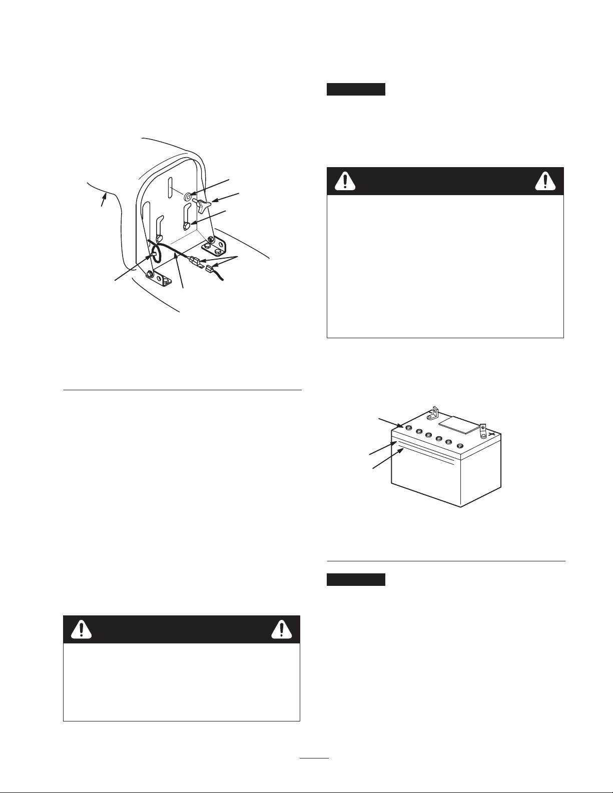
1. Insert the seat switch wire cable through the hole in
the seat base (Fig. 3).
Purchase bulk electrolyte with 1.260 specific gravity from
a local battery supply outlet.
Important Never fill the battery with electrolyte while
the battery is installed in the tractor. Electrolyte could be
spilled on other parts and corrode them.
1. Remove the battery and battery box from the tractor;
refer to Removing the Battery in the Operator ’s
Manual.
5
4
1
3
7
6
2
m-2364
Figure 3
1. Seat
2. Wire and connector
3. Shoulder bolts
4. Knob
5. Flat washer
6. Wire clip
7. Connectors
2. Position the seat onto the seat base by inserting
2 shoulder bolts through the key hole openings at the
end of both slots (Fig. 3).
3. Thread the knob and flat washer through the slot and
into the rear center hole in the seat (Fig. 3).
4. Adjust the seat and tighten the knob.
Danger
Battery electrolyte contains sulfuric acid, a deadly
poison that can severely burn you and others.
• Do not drink electrolyte and avoid contact with
skin, eyes, or clothing. Wear safety glasses to
shield your eyes and rubber gloves to protect
your hands.
• Fill the battery where clean water is always
available for flushing the skin.
• Follow all instructions and comply with all
safety messages on the electrolyte container.
2. Remove the vent caps from the battery.
3. Slowly pour electrolyte into each battery cell until the
electrolyte level is up to the Upper line on the battery
case (Fig. 4).
1
2
3
5. Push the seat switch connector fully into the wire
harness connector (Fig. 3).
6. Secure the seat switch wire cable to the seat base with
the wire clip (Fig. 3).
Note: Check the seat switch wire routing. Ensure that the
wire is not pinched in the seat brackets.
Activating the Battery
Warning
Battery posts, terminals, and related accessories
contain lead and lead compounds, chemicals
known to the State of California to cause cancer
and reproductive harm. Wash hands after
handling.
Figure 4
1. Vent caps
2. Upper line
3. Lower line
Important Do not overfill the battery because
electrolyte (sulfuric acid) can severely corrode and
damage the chassis.
4. Wait 5 to 10 minutes after filling the battery cells.
5. Add electrolyte, if necessary, until the electrolyte level
is up to the Upper line (Fig. 4) on the battery case.
6. Install the battery vent caps.
3
m5004
Page 4
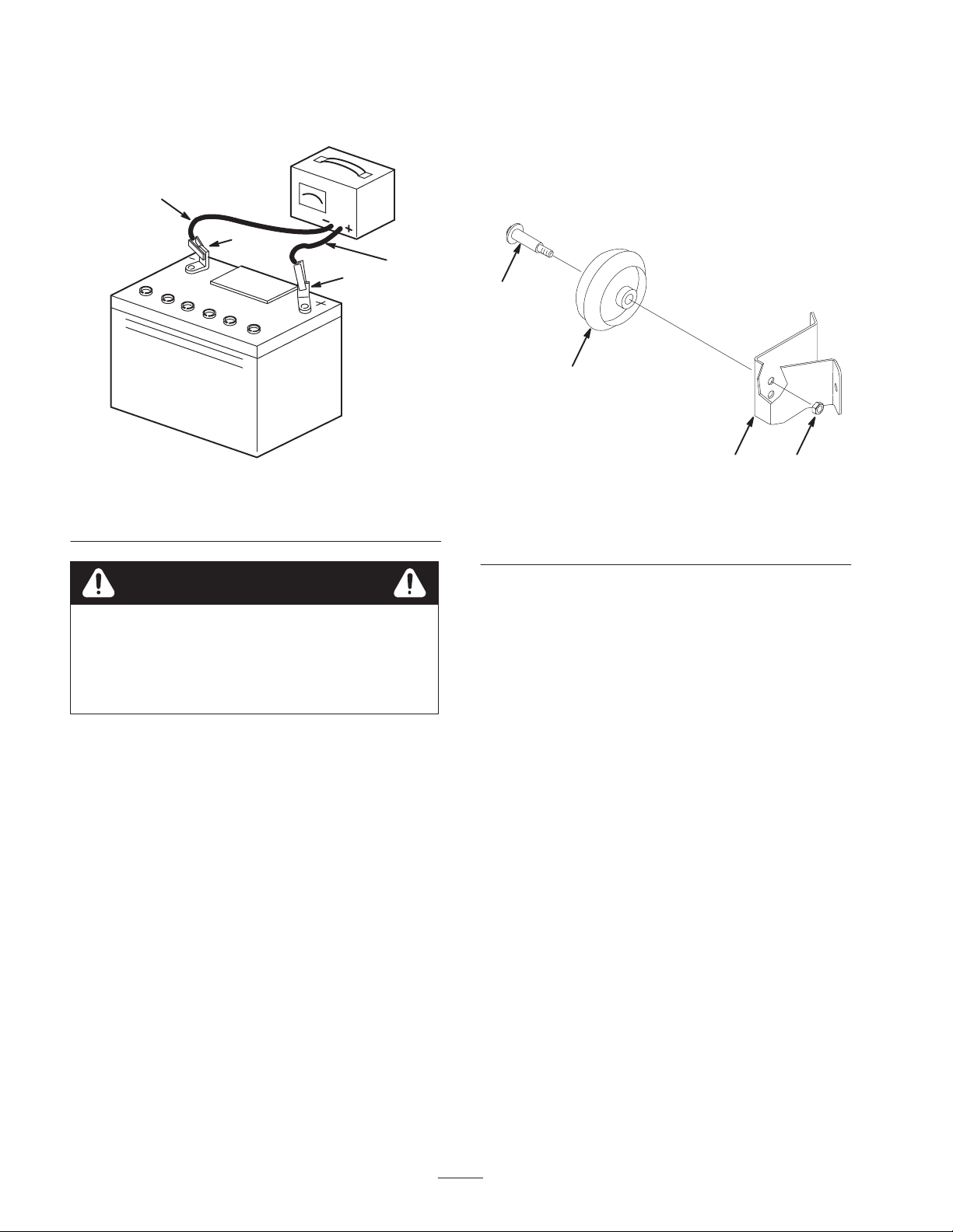
7. Charge the battery for 10 to 15 minutes at 25 to 30
amps or 30 minutes at 4 to 6 amps (Fig. 5). Do not
overcharge the battery.
Installing the Anti-Scalp
Wheels
For 38 Mowers only
4
2
1
Figure 5
1. Positive post
2. Negative post
3. Charger red (+) wire
4. Charger black (–) wire
Warning
Charging the battery produces gasses that can
explode.
1. Mount the wheels onto the wheel brackets with the
wheel bolts and 3/8 in. locknuts (Fig. 6).
3
4
1
2
Figure 6
1. Wheel
2. Wheel bracket
Note: Use the same hole height on both sides; refer to
Adjusting the Mower Wheels in the Operator ’s
Manual.
3. Locknut
4. Wheel bolt
3
m-1505a
Never smoke near the battery and keep sparks
and flames away from battery.
8. When the battery is fully charged, unplug the charger
from the electrical outlet, then disconnect the charger
leads from the battery posts (Fig. 5).
9. Install the battery and battery box in the tractor and
connect the battery cables; refer to Installing the
Battery in the Operator ’s Manual.
Checking the Engine Oil Level
The tractor comes from the factory with oil in the engine
crankcase; however, you may be need to add oil. Refer to
Servicing the Engine Oil in the Operator ’s Manual for oil
type, viscosity, and crankcase capacity. Add only enough
oil to raise the level to the Full mark on the dipstick.
Preparing the Mower
Discharge Chute
For 38 Mowers only
1. Remove the roll pin from the discharge chute spring
and discard the pin.
Note: The roll pin is for shipment only.
2. Ensure that the spring returns the discharge chute to
the full down position.
4
Page 5
Checking the Mower
Adjustment
For 32 Mowers only
The mower was leveled at the factory. However, if the
mower is not cutting level, adjust the side-to-side level
and the front-to-rear blade slope. See the Operator ’s
Manual for the proper procedures.
5
1
2
3
Warning
An improperly adjusted mower can cause the
drive belt to engage the blade at the highest
height-of-cut setting when the blade control (PTO)
lever is in the Disengaged position. Operating the
mower at the highest height-of-cut setting during
or soon after setup may expose you or others to a
rotating blade, causing injury or death.
Never put your hands or feet under the mower or
through any openings in the mower.
To ensure that the mower is properly functioning at the
highest height-of-cut setting during or soon after setup, do
the following:
1. Raise the mower to the highest height-of-cut setting.
2. Ensure that the blade control (PTO) lever is in the
Disengaged position.
3. Start the engine and have someone check if the drive
belt engages or tries to engage the blade.
4. If the drive belt tries to engage or engages the blade,
operate the mower for several minutes at different
height-of-cut settings.
4
m-1805
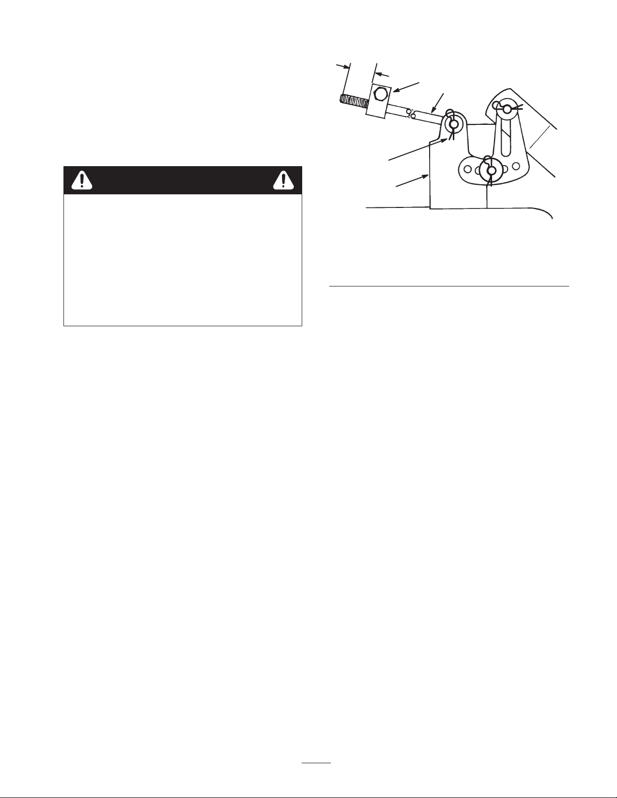
Figure 7
1. Adjusting block
2. Long rod
3. Hairpin cotter and washer
4. Mower mount
5. Length of long rod
extending out
Lubricating the Tractor
Ensure that all of the necessary points on the tractor are
lubricated; refer to Greasing and Lubricating the Tractor
in the Operator ’s Manual.
Checking the Safety Interlock
System
Refer to Testing the Safety Interlock System in the
Operator ’s Manual.
Note: The length of the long rod extending out of the
front of the adjusting block on the sides of the chassis
(Fig. 7) is set to 3/4 in. (19 mm) at the factory. The next
time you adjust the front-to-rear blade slope, set the
length of long rod that extends out to 5/8 in. (16 mm).
5
Page 6
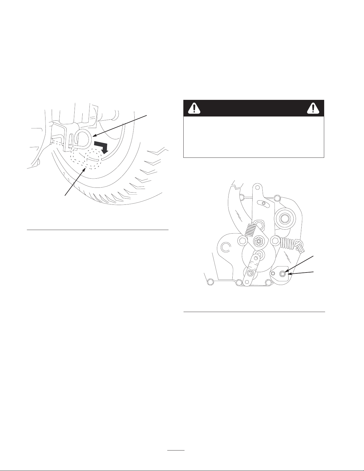
Purging the Hydro Transaxle
For Hydro Drive Tractors only
Shipping and handling can introduce air into the hydro
transaxle. For proper performance, remove all the trapped
air.
1. Move the tractor to a flat, level surface.
2. Place the drive control in the Push position (Fig. 8).
5. Set the parking brake.
6. Stop the engine and wait for all moving parts to stop.
7. Remove the ignition key.
8. Raise the right rear wheel off the ground and support it
with a jack stand.
Note: Ensure that the left rear wheel stays on the
ground.
1
2
Figure 8
1. Operate position 2. Push position
3. Run the engine at a low idle and move the traction
control pedal forward for 5 seconds, then reverse for 5
seconds. Repeat this step 3 times.
4. Place the drive control in the Operate position (Fig. 8)
and drive the tractor forward about 5 feet (1.5 m), then
reverse for about 5 feet (1.5 m). Repeat this step 3
times.
m-4974
Danger
Mechanical or hydraulic jacks may fail to support
the tractor and cause a serious injury.
• Use jack stands when supporting the tractor.
• Do not use hydraulic jacks.
Note: To gain access to the adjusting puck (Fig. 9), you
may need to remove the tire.
1
2
m-4900
Checking the Hydro Neutral
Position
For Hydro Drive Tractors only
Ensure that the neutral position is set properly. If the
tractor moves when the traction control pedal is not
depressed, adjust the neutral position.
1. Run the engine at a low idle and move the traction
control pedal forward, then release.
2. Move the traction control pedal to reverse, then
release. If the tractor moves while it is in the Neutral
position, do the following:
3. Run the tractor for 5 to 10 minutes to warm up the
transaxle.
4. Disengage the blade (PTO).
Figure 9
1. Adjusting puck screw 2. Adjusting puck
9. Loosen the adjusting puck screw (Fig. 9).
10.Start the engine and run it at full throttle.
11. Rotate the adjusting puck (Fig. 9) in both directions
until you find the midpoint where the axle no longer
rotates forward or reverse.
12.Hold the puck with an adjustable wrench so that it will
not move and torque the adjusting puck screw to 21 to
27 ft-lb (28 to 36 N•m).
13.Stop the engine and wait for all moving parts to stop.
14.Remove the ignition key.
15.Lower the tractor from the jack stand.
16.Check the adjustment again by repeating step 1.
6
Page 7
Checking the Traction Control
Pedal
For Hydro Drive Tractors only
You can adjust the traction control pedal for optimum
forward and reverse speeds.
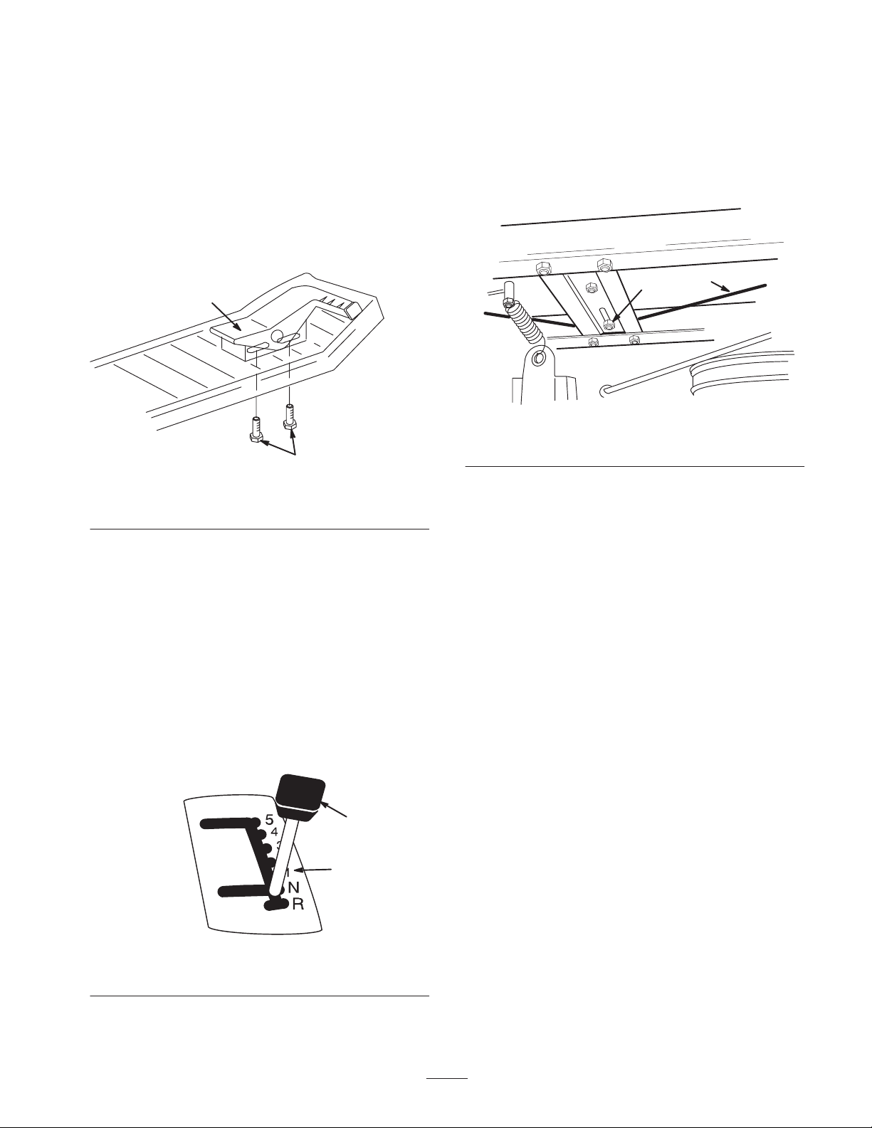
1. Loosen the screws below the right footrest.
2. Slide the pedal forward for a faster reverse speed or
backward for a faster forward speed (Fig. 10).
1. If either of the above conditions exist, turn the engine
off and ensure that the belt guides are no more than 1/8
inch away from the engine and the transmission
pulleys.
2. Check the cable tension. The cable should be taught
and have 1/2 in. (13 mm) movement when you apply a
slight pressure to the cable (Fig. 12).
1
2
Figure 10
1. Traction control pedal 2. Adjusting screws
3. Tighten the screws.
4. Check the traction control pedal.
m-1909
Checking the Shift Cable
Adjustment
For Gear Drive Tractors only
Adjust the shift cable if either the ground speed lever does
not shift firmly toward the numbers on the shift plate
when you release the lever or if it is difficult to shift
on-the-go (Fig. 11).
2
Figure 12
1. Cable 2. Cable guide
3. Move the ground speed lever and note the gap between
the lever and the edge of the gate. There should be
about 1/4 in. (6 mm) of free play before the cable is
taught.
4. Adjust the cable tension by loosening the front cable
guide located on tractor brace above the pulley.
5. Slide the guide sideways as needed, for proper tension
(Fig. 12).
1
1910
Test Driving the Tractor
To ensure that all electrical and mechanical systems are
operating properly, see the Operator’s Manual.
Figure 11
1. Ground speed lever 2. Numbers
1
2
m-1879
7
Page 8

 Loading...