

Page 1
XLSLawnTractors
ForAllXLSLawnTractors
LooseParts
Usethechartbelowtoverifythatallpartshavebeenshipped.
FormNo.3376-118RevA
SetupInstructions
ProcedureDescription
1
2
3
4
5
6
7
8
Qty.
Nopartsrequired
Frontwheel2
Shimwasher(asneeded)
Flatwasher2
Cotterpin
Hubcap2
Nopartsrequired
Steeringwheel
Spiralpin
Seat
Knob2
Flatwasher2
Nopartsrequired
Mowingdeck1Installandadjustthemower.
Nopartsrequired
–
2
2
–
1
1
1
–
–
Connectthebattery.
Installthefrontwheels.
Checkthetirepressure.
Installthesteeringwheel.
Installtheseat.
Checktheengineoillevel.
Lubricatethetractor.
Use
9
10
11
Nopartsrequired
Nopartsrequired
Nopartsrequired
1
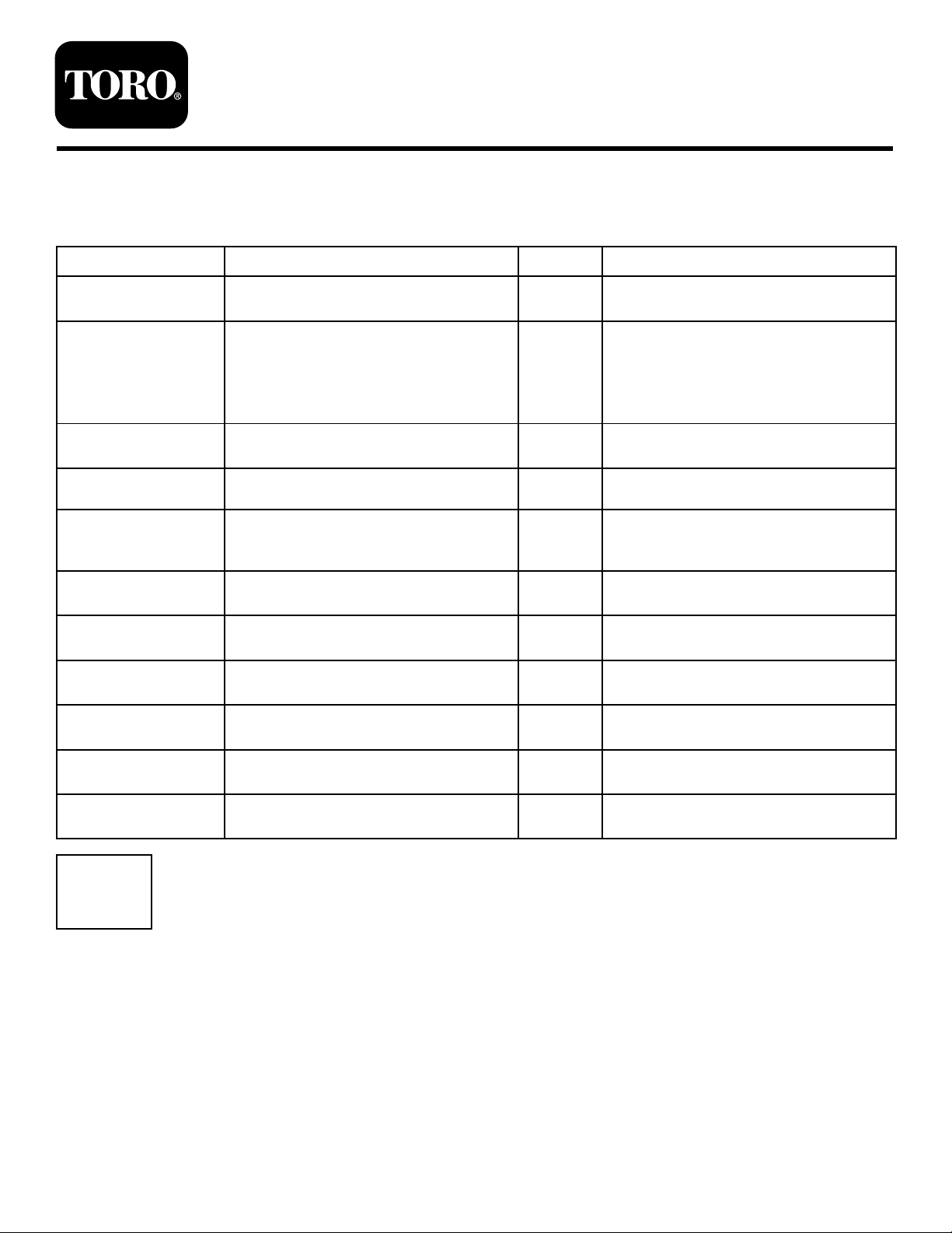
NoPartsRequired
Procedure
1.Locatethebatteryandnegativebatterycable.
2.Removetheplasticcapfromthenegativebatterypost.
3.Removethefastenersonthenegativebatterycableand
usethemtosecurethenegativebatterycabletothe
negativebatterypost(Figure1).
©2012—TheT oro®Company
8111LyndaleAvenueSouth
Bloomington,MN55420
Registeratwww.Toro.com.
–
–
–
Checkthesafetyinterlocksystem.
Testdrivethetractor.
RemovetheEPAdecal.
OriginalInstructions(EN)
PrintedintheUSA
AllRightsReserved
*3376-118*A
Page 2
G017999
1
2
3
4
5
6
Figure1
1.Negativebatterycable4.Negativebatterypostcap
2.Locknut
3.Washer6.Negativebatterypost
5.Carriagebolt
2
InstallingtheFrontWheels
Partsneededforthisprocedure:
2Frontwheel
2
Shimwasher(asneeded)
2Flatwasher
2
Cotterpin
2Hubcap
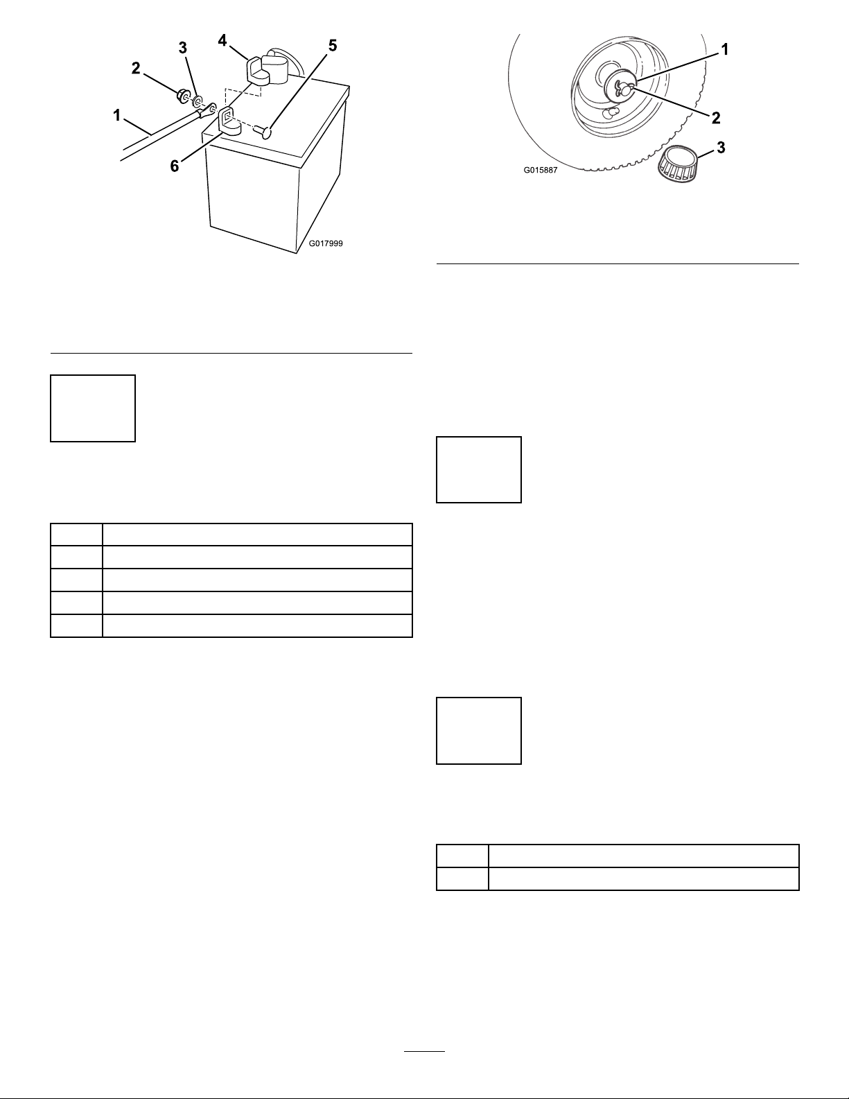
Procedure
Figure2
1.Flatwasher3.Hubcap
2.Cotterpin
Note:Ifthecotterpindoesnott,removetheshim
washer(s)asneeded.
5.Pushthehubcap(Figure2)ontotheendoftheaxle.
6.Repeatsteps1through5ontheoppositesideofthe
tractor.
7.Greasethewheelbearingsuntilthegreasecomesout
ofthebearingsealarea.
3
CheckingtheTirePressure
NoPartsRequired
Procedure
Checkthetirestoensurethattheyareinatedtothe
recommendedpressure.RefertoCheckingtheTirePressure
sectionintheOperator’sManual.
Ifthewheelsarealreadyinstalled,refertoCheckingtheTire
Pressurebelow.
1.Installtheshimwashersontotheaxle.
2.Installthewheelontotheaxlewiththevalvestem
facingoutward.
3.Slidetheatwasherontotheaxle.
4.Insertthecotterpinthroughtheaxleandbendthe
endsofthepinapart(Figure2).
4
InstallingtheSteeringWheel
Partsneededforthisprocedure:
1
Steeringwheel
1
Spiralpin
Procedure
1.Movethefrontwheelssothattheyfacestraightahead.
2.Slidethesteeringwheeloverthesteeringshaftandline
uptheholeinthesteeringwheelwiththeholeinthe
shaft(Figure3).
2
Page 3

Figure3
1.Steeringwheel2.Spiralpin
Note:Fromtheseatyoushouldbeabletoeasilyread
thebrandlogoonthesteeringwheel.
Figure4
1.Seat4.Seatswitch
2.Shoulderbolts5.Seatbase
3.Knobsandatwashers
3.Aligntheholesbyinsertingapunchoralongnail
partiallythroughtheholesinthesteeringwheeland
shaft.
4.Insertthespiralpinintotheholeontheoppositeside.
5.Usingahammer,drivethespiralpininuntilitisush
withtheoutsideofthesteeringwheel(
Figure3).
5
InstallingtheSeat
Partsneededforthisprocedure:
1
Seat
2Knob
2Flatwasher
Procedure
1.Positiontheseatontotheseatbasebyinserting2
shoulderboltsthroughthekeyholeopeningsatthe
endofbothslots(Fig.3).
2.Threadtheknobsandatwashersthroughtheslots
andintotherearcenterholesintheseat(Figure4).
3.Adjusttheseatandtightentheknobs.
4.Connecttheseatswitchtothewireharnessconnector
(Figure4).
Note:Ensurethatthewiringisnotpinchedinthe
seatbrackets.
6
CheckingtheEngineOilLevel
NoPartsRequired
Procedure
Thetractorcomesfromthefactorywithoilintheengine
crankcase;however,youmaybeneedtoaddoil.Referto
ServicingtheEngineOilintheOperator’sManualforoiltype,
viscosity,andcrankcasecapacity.Addonlyenoughoiltoraise
theleveltotheFullmarkonthedipstick.
3
Page 4

7
1
g016928
10
InstallingandAdjustingthe
Mower
Partsneededforthisprocedure:
1Mowingdeck
Procedure
Installthemowingdeckandadjustboththeside-to-sidelevel
andthefront-to-rearbladeslope.SeethechapteronBlade
MaintenanceintheOperator'sManualfortheprocedures:
InstallingtheMower,LevelingtheMowerfromSide-to-Side,
andtoAdjustingtheFront-to-RearBladeSlope.
8
LubricatingtheTractor
NoPartsRequired
TestDrivingtheTractor
NoPartsRequired
Procedure
Toensurethatallelectricalandmechanicalsystemsare
operatingproperly,seetheOperator’ sManual.
11
RemovingtheEPADecal
NoPartsRequired
Procedure
Thedecalshownin
saleoutsideoftheUnitedStatesofAmerica.Thisdecalis
locatedasshownin
Figure5mayberemovedatpointsof
Figure6.
Procedure
Ensurethatallofthenecessarypointsonthetractorare
lubricated;refertoGreasingandLubricatingtheTractorin
theOperator’sManual.
9
CheckingtheSafetyInterlock System
NoPartsRequired
Procedure
RefertoTestingtheSafetyInterlockSystemintheOperator’s
Manual.
Figure5
Figure6
4
 Loading...