

Page 1
FormNo.3404-698RevB
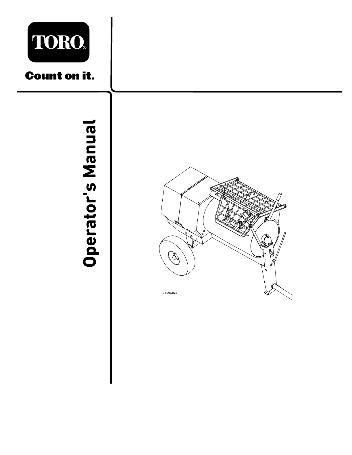
MM-858H-PMortarMixer
ModelNo.68021HD—SerialNo.316000001andUp
Registeratwww.T oro.com.
OriginalInstructions(EN)
*3404-698*B
Page 2
WARNING
CALIFORNIA
Proposition65Warning
Thisproductcontainsachemicalorchemicals
knowntotheStateofCaliforniatocausecancer,
birthdefects,orreproductiveharm.
Theengineexhaustfromthisproduct
containschemicalsknowntotheStateof
Californiatocausecancer,birthdefects,
orotherreproductiveharm.
Useofthisproductmaycauseexposureto
chemicalsknowntotheStateofCalifornia
tocausecancer,birthdefects,orother
reproductiveharm.
ThissparkignitionsystemcomplieswithCanadianICES-002.
Becauseinsomeareastherearelocal,state,orfederal
regulationsrequiringthatasparkarresterbeusedonthe
engineofthismachine,asparkarresterisavailableas
anoption.Ifyourequireasparkarrester,contactyour
AuthorizedToroServiceDealer.
YoumaycontactT orodirectlyatwww .Toro.comforproduct
safetyandoperationtrainingmaterials,accessoryinformation,
helpndingadealer,ortoregisteryourproduct.
Wheneveryouneedservice,genuineToroparts,oradditional
information,contactanAuthorizedServiceDealerorToro
CustomerServiceandhavethemodelandserialnumbersof
yourproductready .Writethenumbersinthespaceprovided.
GenuineT orosparkarrestersareapprovedbytheUSDA
ForestryService.
ItisaviolationofCaliforniaPublicResourceCode
Section4442or4443touseoroperatetheengineonany
forest-covered,brush-covered,orgrass-coveredlandunless
theengineisequippedwithasparkarrester,asdenedin
Section4442,maintainedineffectiveworkingorderorthe
engineisconstructed,equipped,andmaintainedforthe
preventionofre.
Theenclosed
informationregardingtheUSEnvironmentalProtection
Agency(EPA)andtheCaliforniaEmissionControl
Regulationofemissionsystems,maintenance,and
warranty.Replacementsmaybeorderedthroughthe
enginemanufacturer.
Engine Owner's Man ual
issuppliedfor
Introduction
Thismachineisdesignedtomixmortar,plaster,reproong
material,grout,andothersmall-grainedPortlandcement
products.Avehicleequippedwithanappropriatepintlehitch
orballhitchcantowthemachine.
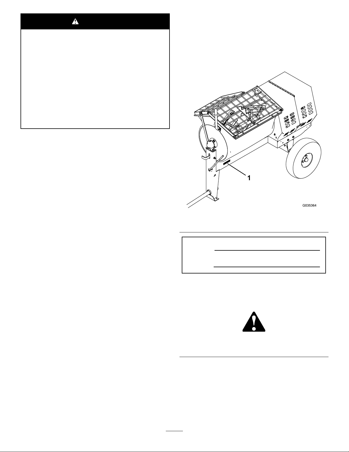
Figure1
1.Modelandserialnumberlocation
ModelNo.
SerialNo.
Thismanualidentiespotentialhazardsandhassafety
messagesidentiedbythesafety-alertsymbol(Figure2),
whichsignalsahazardthatmaycauseseriousinjuryordeath
ifyoudonotfollowtherecommendedprecautions.
Figure2
1.Safety-alertsymbol
Readthisinformationcarefullytolearnhowtooperateand
maintainyourproductproperlyandtoavoidinjuryand
productdamage.Youareresponsibleforoperatingthe
productproperlyandsafely.
©2016—TheToro®Company
8111LyndaleAvenueSouth
Bloomington,MN55420
Contactusatwww.Toro.com.
2
PrintedintheUSA
AllRightsReserved
Page 3

Thismanualuses2wordstohighlightinformation.
Importantcallsattentiontospecialmechanicalinformation
andNoteemphasizesgeneralinformationworthyofspecial
attention.
TireInformation
TheDOTtireinformationislocatedonthesideofeachtire.
Thisinformationgivesloadandspeedratings.Replacement
tiresshouldhavethesameorbetterratings.
Note:Thevariousmachinesinthismanualhavedifferent
weights;refertoSpecications(page13)toensurethatthe
tiresonyourmachinemeetorexceedtheweightrequirements
ofyourmachine.
Contents
Safety...........................................................................4
SafeOperatingPractices...........................................4
SafetyandInstructionalDecals.................................7
Setup............................................................................9
1InstallingtheDumpHandle...................................9
2InstallingtheTowPole..........................................10
3InstallingtheSafetyChain.....................................10
ProductOverview.........................................................11
Controls...............................................................11
Specications........................................................13
Operation....................................................................13
PreparingtoT owtheMachine..................................13
ExtendingtheAxle.................................................17
TowingtheMachine...............................................18
PreparingtoUsetheMachine...................................18
OpeningandClosingtheCowl.................................18
AddingFuel...........................................................19
CheckingtheEngine-OilLevel.................................21
StartingandShuttingOfftheEngine.........................21
ControllingthePaddles...........................................22
MixingtheMaterial.................................................23
UsingtheDrum.....................................................24
AdjustingthePaddleBlades.....................................24
Maintenance.................................................................26
RecommendedMaintenanceSchedule(s)......................26
PremaintenanceProcedures........................................27
PreparingtheMachineforMaintenance.....................27
DisconnectingtheSpark-PlugWire...........................27
RemovingandInstallingtheDividerPlate..................27
Lubrication...............................................................28
LubricatingtheBearingsandSeals............................28
EngineMaintenance..................................................29
ServicingtheAirCleaner.........................................29
ServicingtheEngineOil..........................................30
ServicingtheSparkPlug..........................................31
ServicingtheSparkArrester.....................................33
RemovingandInstallingtheEngine..........................33
FuelSystemMaintenance...........................................35
CleaningtheFuel-SedimentCup...............................35
DrainingtheFuelTank...........................................35
BeltMaintenance......................................................36
ServicingtheBelts—Belt-driveModels......................36
ReplacingtheBelts—Belt-driveModels.....................37
AligningthePulleys................................................39
Cleaning...................................................................39
CleaningtheMachine..............................................39
Storage........................................................................40
StoringtheMachine................................................40
Troubleshooting...........................................................41
3
Page 4

Safety
Improperlyusingormaintainingthemachinecanresult
ininjury.T oreducethepotentialforinjury,complywith
thesesafetyinstructionsandalwayspayattentiontothe
safety-alertsymbol,whichmeans:
or
Danger
complywiththeinstructionmayresultinpersonalinjury
ordeath.
—personalsafetyinstruction.Failureto
Caution
,
W ar ning
•Neverletchildrenoruntrainedpeopleoperateorservice
theequipment.Localregulationsmayrestricttheageof
theoperator.
•Theowner/usercanpreventandisresponsiblefor
accidentsorinjuriestopeopleordamagetoproperty.
,
Towing
Checkwithyourlocalcountyorstatetowingsafetyregulations
beforetowingthemachine.
SafeOperatingPractices
Thisproductiscapableofamputatinghands.Alwaysfollow
allsafetyinstructionstoavoidseriousinjuryordeath.
WARNING
Machiningorhandlingstone,masonry,concrete,
metal,andothermaterialscangeneratedust,mists,
andfumescontainingchemicals,suchassilica,
knowntocauseseriousorfatalinjuryorillness,
suchasrespiratorydisease,silicosis,cancer,birth
defects,orotherreproductiveharm.
•Controldust,mist,andfumesatthesource
wherepossible.Watershouldbeusedfordust
suppressionwhenfeasible.
•Usegoodworkpracticesandfollowthe
recommendationsofthemanufactureror
suppliers,OSHA,andotheroccupationaland
tradeassociations.
•Alwaysfollowrespiratoryprecautions.
•Whenthehazardsfrominhalationcannotbe
eliminated,theoperatorandanybystanders
shouldweararespiratorapprovedbyOSHAfor
thematerialbeinghandled.
•Inordertoreducethepossibilityofanaccidentwhile
transportingthemachineonpublicroads,makesurethat
thetowingvehicleismechanicallysoundandingood
operatingcondition.
•Shutdowntheenginebeforetransportingthemachine.
•Whentowingwithaballhitch,ensurethattheballhitch
youareusingisthepropersizeforthehitchcoupleron
themachine.
•Whentowingwithapintlehitch,ensurethattheeyeof
thetowpoleisthecorrectdimensionforthepintlehook.
•Inspectthehitchandcouplingforwear.Nevertowthe
machinewithdamagedordefectivehitches,couplings,
chains,orothercomponents.
•Checkthetireairpressureonthetowingvehicleandthe
machine.
•Checkthetiretreadandsidewallfordamageandwear.
•Properlyattachthesafetychainstothetowingvehicle.
•Ensurethatthedirectionalandbrakelightsareworking
properly(ifthemachineisequippedwiththelightkit).
•Ensurethatthedirectional,backup,andbrakelightsof
thetowvehicleareworkingproperly(ifthemachineis
equippedwiththelightkit).
•Beforetowing,checktomakecertainyourmachineis
correctlyandsecurelyattachedtothetowingvehicle.
WARNING
Engineexhaustcontainscarbonmonoxide,an
odorless,deadlypoisonthatcankillyou.
Donotruntheengineindoorsorinanenclosed
area.
Training
•ReadtheOperator'sManualandothertrainingmaterial.If
theoperator(s)ormechanic(s)cannotreadorunderstand
theinformation,itistheowner'sresponsibilitytoexplain
thismaterialtothem.
•Becomefamiliarwiththesafeoperationoftheequipment,
operatorcontrols,andsafetysigns.
•Alloperatorsandmechanicsshouldbetrained.The
ownerisresponsiblefortrainingtheusers.
•Ensurethatthesafetychainsareproperlysecuredtothe
vehicle,andleaveenoughslackforturning.
•Donotcarryanymaterialinthemachinewhentowing.
•Avoidsuddenstopsandstarts.Thiscancauseskidding,
orjackkning.Smooth,gradualstartsandstopswill
improvetowing.
•Avoidsharpturnstopreventrolling.T owonlywitha
vehiclethathasahitchdesignedfortowing.Donot
attachtowedequipmentexceptatthehitchpoint.
•Donottowthemachinefasterthan88km/h(55mph).
•Usecautionwhenbackingup;useaspotteroutsidethe
vehicletoguideyou.
•Donotallowanyonetositorrideonthemachine.
•Disconnectthemachinefromthetowvehiclebefore
usingit.
•Securethemachinefrommovementbeforeyoutowit.
4
Page 5

Preparation
Becomefamiliarwiththesafeoperationoftheequipment,
operatorcontrols,andsafetysigns.
•Useonlyaccessoriesandattachmentsapprovedbythe
manufacturer.
•Wearpersonalprotectiveequipmentandappropriate
clothing,includingthefollowing:
–Hardhat
–Respiratorordustmask
–Faceshield
–Hearingprotection
–Substantial,slip-resistantfootwear
–Longpants
–Shirtwithlongsleevesthataretightatthewrists
–Tight-ttinggloveswithoutdrawstringsorloosecuffs
•Securelooseclothing,tiebacklonghair,anddonotwear
jewelry.
•Operatingtheequipmentsafelyrequiresthefullattention
oftheoperator.Donotwearradioormusicheadphones
whileoperatingthemachine.
•Useextracarewhenhandlingfuels.Theyareammable
andthevaporsareexplosive.Usethefollowingpractices
whenhandlingfuel:
–Useonlyanapprovedfuelcontainer.
–Neverremovethefuelcaporaddfuelwiththeengine
running.
–Allowtheenginetocoolbeforerefueling.
–Donotsmoke.
–Neverrefuelordrainthemachineindoors.
–Replacethefuelcapandtightenitsecurely .
–Keepthecontainernozzleincontactwiththetank
duringlling.
–Neverllacontainerwhileitisinsideavehicle,trunk,
pick-upbed,oranysurfaceotherthantheground.
–Neverstorethemachineorfuelcontainerinside
wherethereisanopename,suchasnearawater
heaterorfurnace.
–Iffuelisspilled,wipeitofftheengineandequipment.
•Ensurethatthemachineisonalevelsurfacebefore
operatingthemachine.
•Securethemachinefrommovementbeforeyoubegin
toworkonit
•Beforeeveryuse,dothefollowing:
–Inspectthecoupler,ball,andhitch.
–Ensurethatalllightsarefunctioningproperly(ifthe
machineisequippedwithalightkit).
–Ensurethatthetiresareproperlyinatedas
recommended.
–Ensurethatthelugnutsaretightandtorqued
properly.
–Ensurethatthemachineisproperlysecured.
Operation
•Neverrunanengineinanenclosedorpoorlyventilated
area.
•Onlyoperatethemachineingoodlightingconditions.
•Beforestartingthemachine,makesurethatthereareno
personsorobstaclesnearorunderthemachine.
•Shutofftheenginebeforeleavingthemachineforany
reason.
Neverleavearunningmachineunattended.Always
shutofftheengineandverifythatallmovingpartshave
stopped.
•Avoidprolongedbreathingofexhaustfumes.Engine
exhaustfumescancausesicknessordeath.
•Keephandsawayfromanymovingparts.Keepfeetaway
fromthetiresandthefrontpost.
•Donotoperatethemachinewhileill,tired,orunderthe
inuenceofalcoholordrugs.
•Ensurethattheareaisclearofotherpeopleorpetsbefore
operatingthemachine.Shutoffthemachineifanyone
entersthearea.
•Neverplaceyourhandsoranysolidobjectintothedrum
whenthemachineisinoperation.
•Donottouchpartswhichmaybehotfromoperation.
Allowthemtocoolbeforeattemptingtomaintain,adjust,
orservicethemachine.
•Nevermovethemachinewhiletheengineisrunning.
•Keepthecowlclosedandlatchedduringoperation.
•Ensurethatalltheguardsandshieldsaresecurelyinplace
beforeoperatingthemachine.
•Ifthemixingpaddlesstrikeaforeignobjectorifthe
machineshouldstartmakinganunusualnoiseor
vibration,shutofftheengineandemptythedrum.W ait
forallmovingpartstocometoacompletestopandcool.
Vibrationisgenerallyawarningoftrouble.Inspectfor
cloggingordamage.Cleanandrepairand/orreplace
damagedparts.
•Donotchangetheenginegovernorsettingoroverspeed
theengine.
•Lightningcancausesevereinjuryordeath.Ifyousee
lightningorhearthunderinthearea,donotoperatethe
machine;seekshelter.
5
Page 6

MaintenanceandStorage
•Beforeperformingmaintenance,dothefollowing:
–Parkthemachineonlevelground.
–Shutofftheengine.W aitforallmovementtostop
beforeadjusting,cleaning,orrepairing.
–Lettheenginecoolbeforeperformingmaintenance
orstoring.
–Disengageallpowerandoperationcontrols.
•Neverlubricate,service,repair,oradjustthemachine
whileitisrunning.
•Keepequipmentmaterialsclearfromthemuferand
enginetohelppreventres.Cleanupanyoilorfuel
spillage.
•Neverallowuntrainedpersonneltoservicethemachine.
•Keephands,feet,andclothingawayfrommovingparts.
Ifpossible,donotmakeadjustmentswiththeengine
running.
•Keepallpartsingoodworkingconditionandallhardware
tightened.Replaceallwornordamageddecals.
•Removeanybuildupofgrease,oil,ordebrisfromthe
machine.
•Stopandinspectthemachineifaforeignobjectentersthe
drumorcausesanotherobstruction.Makeanynecessary
repairsbeforestartingthemachine.
•Donottamperwithsafetydevices.
•Securethemachinefrommovementwhenstoringthe
machine.
•Keepallnuts,bolts,screws,andhoseclampssecurely
tightened.Keepequipmentingoodcondition.
•UseonlygenuineTororeplacementpartstoensurethat
theoriginalstandardsaremaintained.
6
Page 7
SafetyandInstructionalDecals
Safetydecalsandinstructionsareeasilyvisibletotheoperatorandarelocatednearanyareaofpotential
danger.Replaceanydecalthatisdamagedorlost.
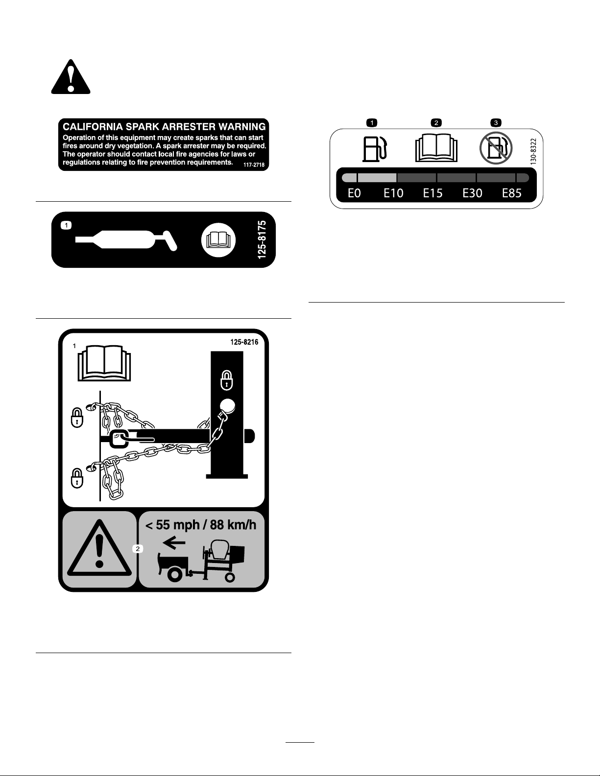
117-2718
130-8322
125-8175
1.ReadtheOperator’sManualforinformationongreasing
themachine.
1.Onlyusefuelwithan
alcoholcontentbyvolume
under10%.
2.ReadtheOperator's
Manualformore
informationonfuel.
3.Donotusefuelwithan
alcoholcontentbyvolume
greaterthan10%.
1.ReadtheOperator’s
Manualforinformationon
howtotowthemachine.
125-8216
2.Warning—limittowing
speedtolessthan55mph
/88km/h.
7
Page 8
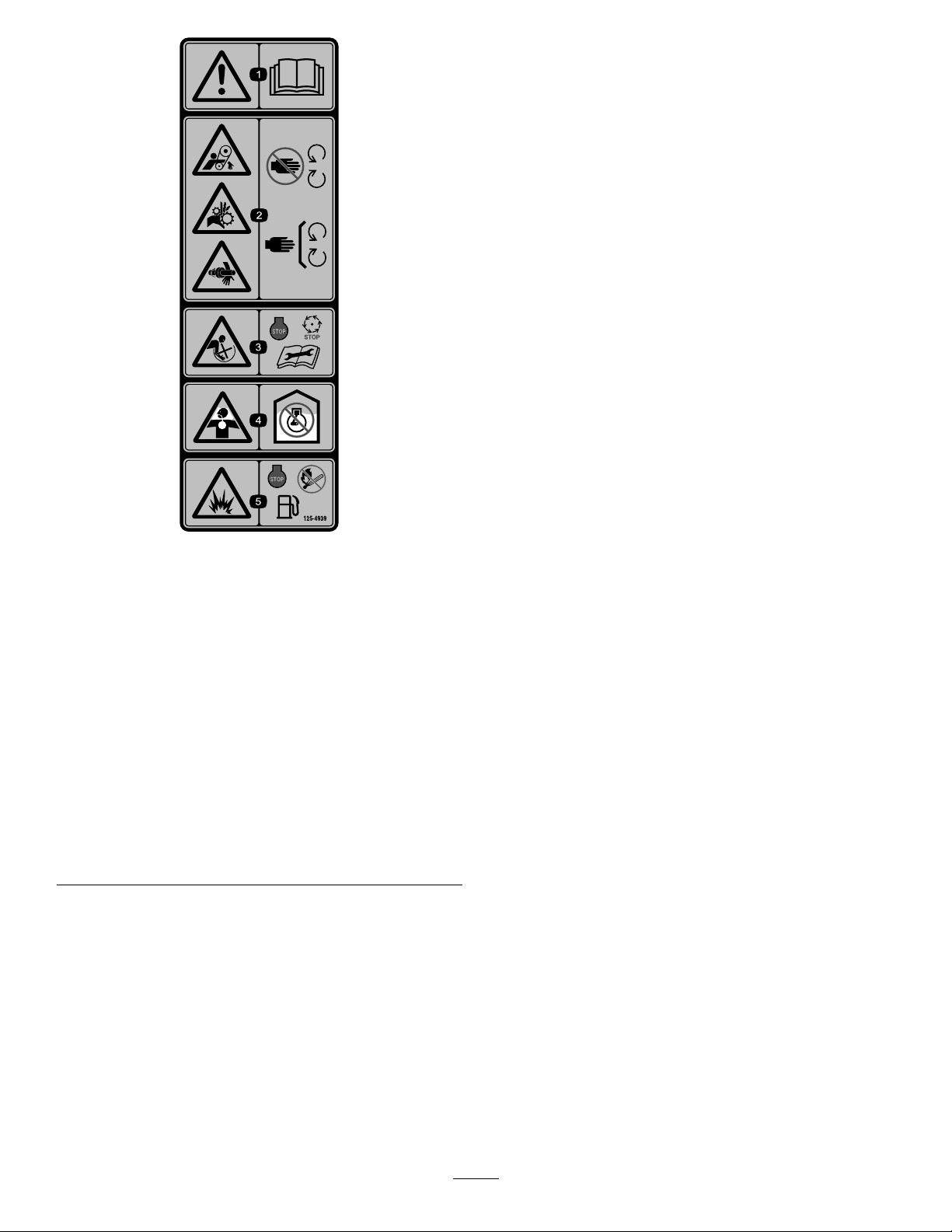
125-4939
1.Warning—readthe
Operator’sManual.
2.Handandarm
entanglementatthe
beltdrive;crushinghazard
ofhand;entanglement
hazardofhandatthe
shaft—keephandsaway
frommovingparts;keep
allguardsandshieldsin
place.
3.Entanglementhazard
atpaddles—shutoff
theengineandwait
forallmovingpartsto
stopbeforeperforming
maintenance.
4.Toxicgasinhalation
hazard—Don’trunthe
engineinanenclosed
space.
5.Explosionhazard—shut
offtheengineandkeep
awayfromameswhen
refueling.
8
Page 9
Setup
G022150
LooseParts
Usethechartbelowtoverifythatallpartshavebeenshipped.
ProcedureDescription
1
2
3
1
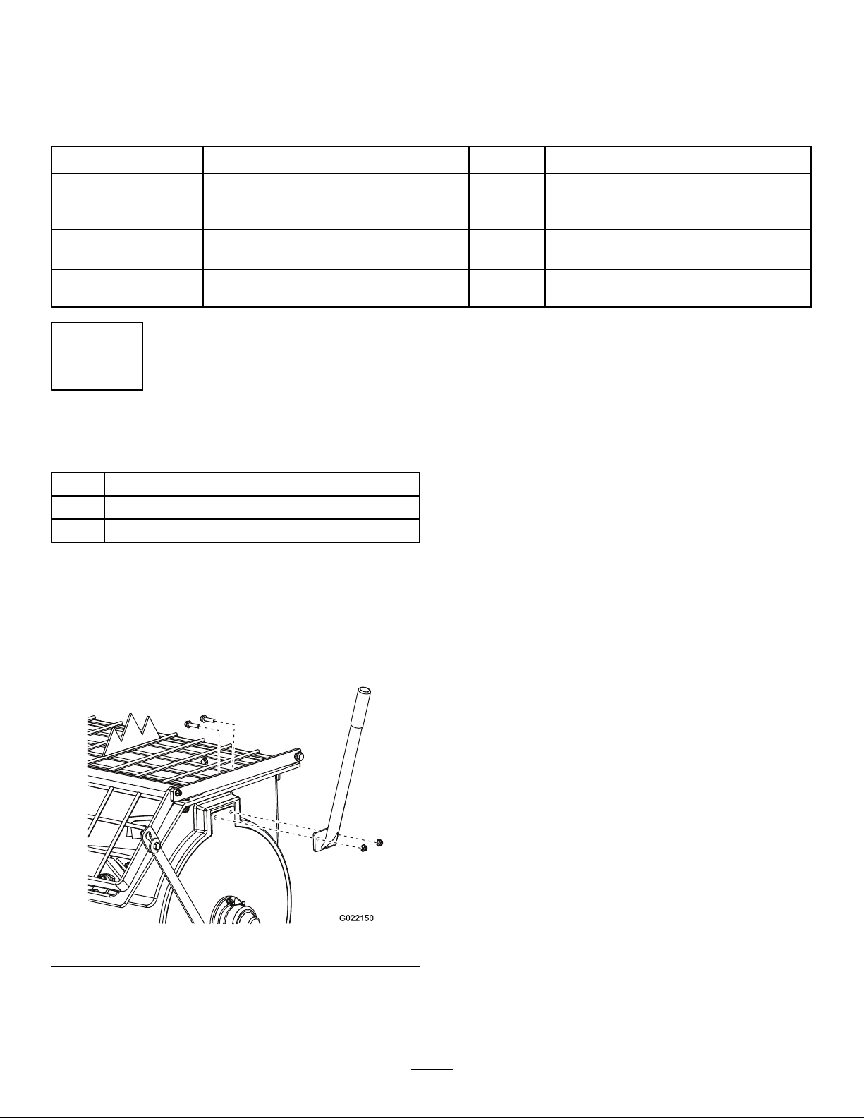
InstallingtheDumpHandle
Partsneededforthisprocedure:
1Dumphandle
2Bolt
2Nut
Dumphandle1
Bolt2
Nut2
Towpolekit(soldseparately)
Safetychain
Connectinglink
3.Insertthe2boltsthroughtheboltholesinthedump
handleandthedrum(Figure3).
4.Installanutontoeachbolt,andtightenthembyhand
topreventcross-threading.
5.Tightenthenutswithawrenchwhileusinganother
wrenchtokeeptheboltsfromspinning.
Qty.
Installthedumphandle.
1Installthetowpole.
1
2
Installthesafetychain.
Use
InstallingtheDumpHandletotheDrum
1.Cutthecabletiestoremovethedumphandlefrom
theundersideofthegrate.
2.Positionthedumphandlesothattheboltholesalign
withtheboltholesinthedrum(Figure3).
Figure3
9
Page 10
2
5
1
2
4
6
3
G019804
3
InstallingtheTowPole
Partsneededforthisprocedure:
1
Towpolekit(soldseparately)
Procedure
Note:Thetowpoleispurchasedseparatelyandincludesthe
nutandboltneededforinstallation.
Themachinehasthefollowingtowpoleoptions:
HitchT ypeLength
50mm(2inch)ball—stamped78.7cm(31inches)
50mm(2inch)ball—forged78.7cm(31inches)
Pintle
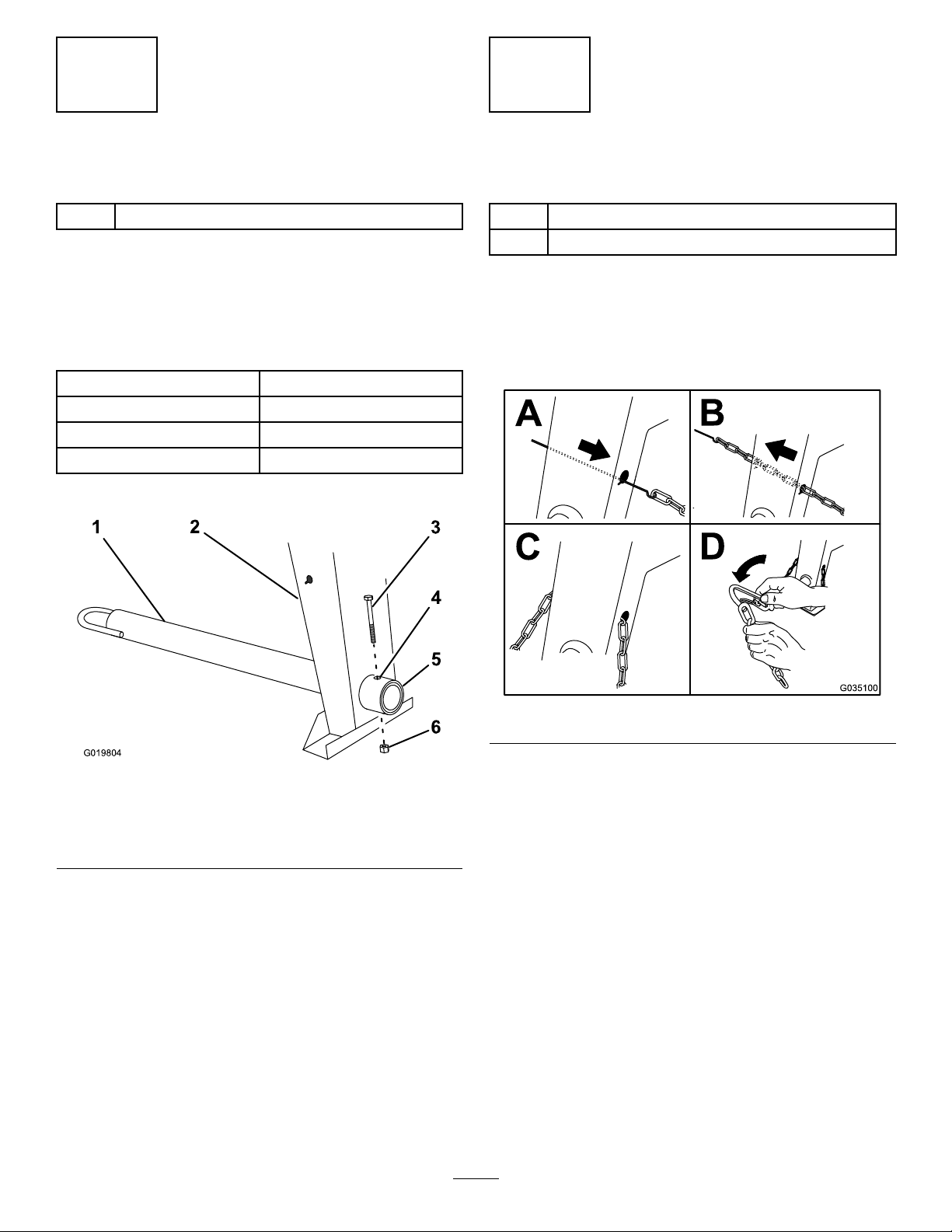
1.Removetheboltandnutfromthetowpole(Figure4).
78.7cm(31inches)
InstallingtheSafetyChain
Partsneededforthisprocedure:
1
Safetychain
2
Connectinglink
Procedure
Formahookontheendofabendablepieceofrodorstiff
wire,(notincluded),andinstallthesafetychainasshownin
Figure5.
Figure5
Figure4
1.Towpole4.Bolthole
2.Frontpost
3.Bolt6.Nut
2.Slidethetowpoleforwardandaligntheholeinthe
polewiththeholeintheframetting(Figure4).
3.Inserttheboltthroughtheholesinthettingandthe
pole(Figure4).
4.Threadthenutontotheboltandtightenthemuntil
theyaretightagainsttheframetting(Figure4).
Note:Iftheself-lockingnyloninsertinthelocknut
wearswithuse,replacethenutwithanewGrade5or
Grade8locknut.
5.Frametting
Note:Ensurethatapproximatelyequallengthsofsafety
chainextendfromeithersideofthefrontpost.
10
Page 11
ProductOverview
G019875
1
Controls
Becomefamiliarwithallthecontrolsbeforeyoustartthe
engineandoperatethemachine.
ClutchLever
Theclutchleverengagesanddisengagesenginepowertothe
paddles(Figure7).
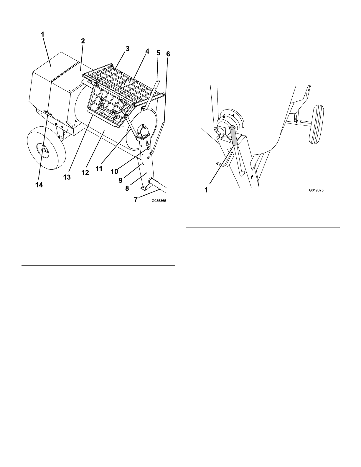
Figure6
1.Rearcowl
2.Frontcowl7.Towpole12.Drum
3.Grate
4.Bagsplitter
5.Dumphandle10.Drumlatch
6.Clutchlever11.Grateliftarm
8.Frontpost
9.Safety-chain
keyhole
Figure7
Belt-drivemodels
1.Clutchlever
13.Chute
14.Cowllatch
11
Page 12
DrumLatch
1
G019877
1
2
3
4
5
6
7
8
G019744
1
2
3
G018792
FuelValve
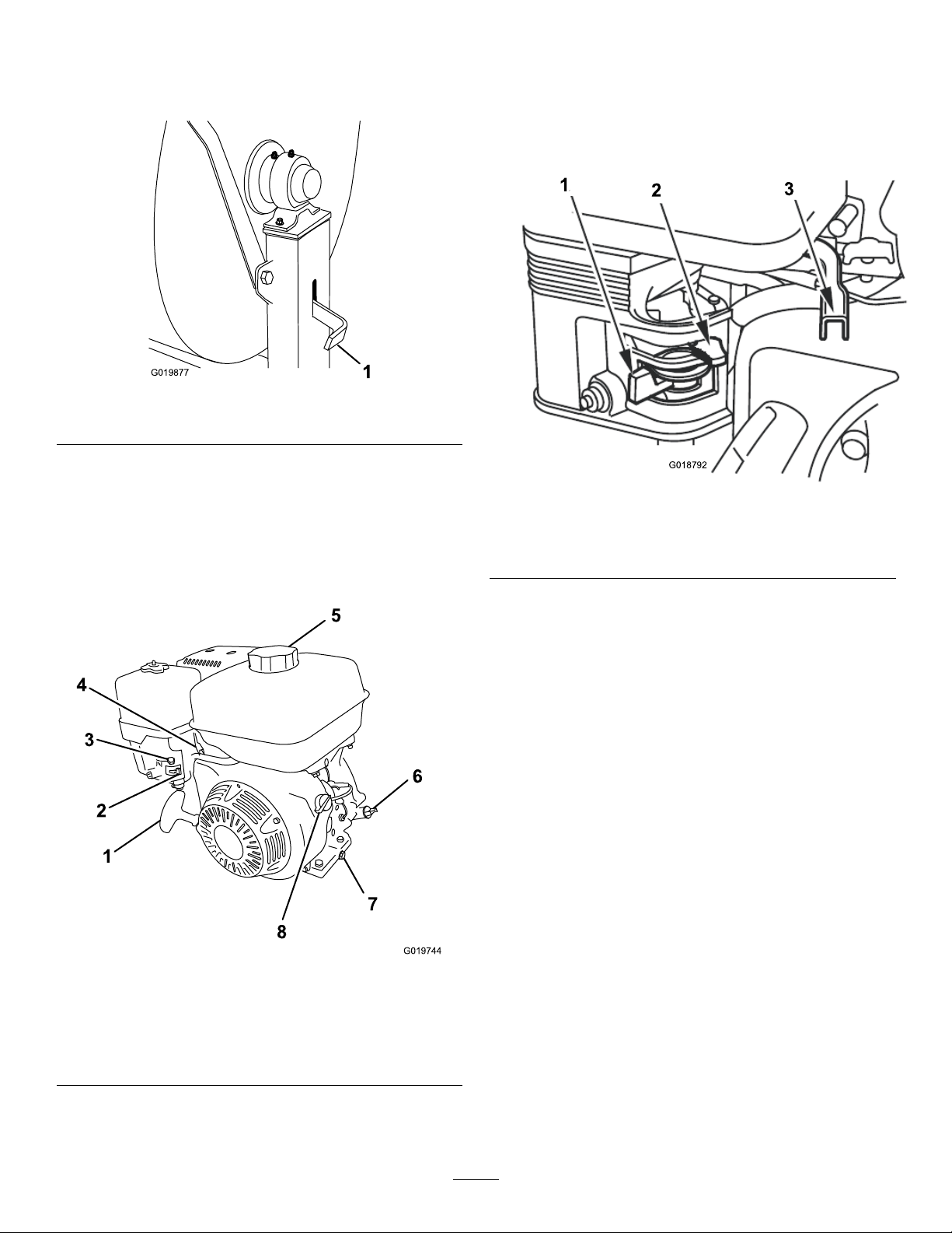
Thedrumlatchsecuresthedrumtothemixposition(upright)
formixingoperationsandwhentransportingthemachine.
Figure8
1.Drumlatch
DumpHandle
Usethedumphandletorotatethedrumtothedumpposition
andtorotatethedrumtothemixposition(upright).
Thefuelvalve(Figure10)islocatedunderneaththechoke
lever.MovetheleverforthefuelvalvetotheONposition
beforeattemptingtostarttheengine.Whenyouhavenished
mixing,shutofftheengineandmovethefuelvalveleverto
theOFFposition.
Figure10
1.Fuelvalve3.Throttlelever
2.Chokelever
EngineControls
ChokeLever
Usethechokelever(Figure10)tostartacoldengine.Before
pullingtherecoil-starthandle,movethechokelevertothe
CLOSEDposition.Oncetheengineisrunning,movethe
chokelevertotheOPENposition.Donotusethechokeifthe
engineisalreadywarmeduporiftheairtemperatureishigh.
ThrottleLever
Thethrottlelever(Figure10)controlsthespeed(rpm)ofthe
engine.Itislocatednexttothechokelever.Itsetstheengine
speedandthereforecanincreaseanddecreasetherotation
speedofthemixingpaddles.Forbestperformance,setthis
1.Recoil-starthandle5.Fuelcap
2.Fuelvalve6.Dipstick
3.Chokelever7.Oil-drainplug
4.Throttlelever
Figure9
8.On/Offswitch
controltotheFASTpositionwhenmixingmaterial.
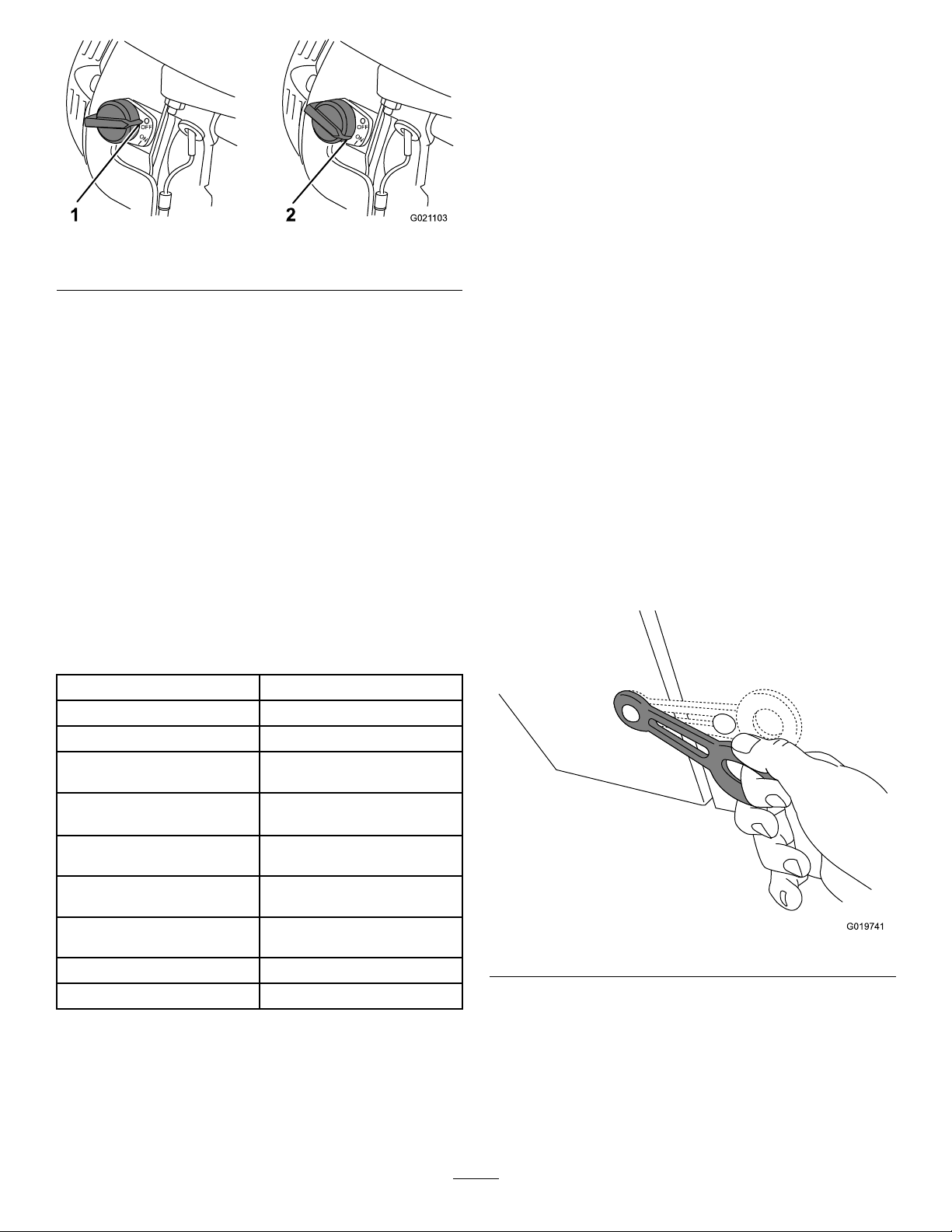
EngineOn/OffSwitch
UsetheOn/Offswitch(Figure11)tostartandshutoffthe
engine.Thisswitchislocatedonthefrontoftheengine.
RotatetheOn/OffswitchtotheONpositiontostartandrun
theengine.RotatetheOn/OffswitchtotheOFFposition
toshutofftheengine.
12
Page 13
OFF
ON
1
OFF
ON
G021 103
2
Operation
G019741
PreparingtoTowtheMachine
Important:Ensurethatyourtowvehiclehastowing
capacityfortheweightofthemachine.
Important:UseaClass2orlargerreceiver.
Figure11
1.Offposition2.Onposition
Recoil-startHandle
Tostarttheengine,pulltherecoil-starthandle(Figure9)
quicklytoturntheengineover.Theenginecontrolsdescribed
abovemustallbesetcorrectlyfortheenginetostart.
Oil-levelSwitch
Theoil-levelswitchislocatedinsidetheengine,anditdoes
notallowtheenginetorunintheeventtheoillevelisbelow
thesafeoperatinglimit.
Specications
Note:Specicationsanddesignaresubjecttochange
withoutnotice.
MachineSpecications
Note:Ensurethatyourtowvehiclehastheappropriatehitch
totowthemachine;optionsincludea50mm(2inch)ball
hitchorapintlehitch.
Note:Ifthemachineisequippedwithatrailer-lightkit,
ensurethattheelectricalconnectorofthetowvehicleis
compatiblewiththeelectricalconnectorofthemachine.The
machineusesastandard4-atplug.Ifyourtowvehiclehasa
differenttypeofplug,obtainanadapterfromanautomotive
partsstore.
1.Ensurethattheengineisshutoff,thefuelvalveisin
theOFFposition,andthedrumisempty.
2.Ifthedrumhasaccumulatedanywater,dumpthe
drum;refertoDumpingtheDrum(page24),steps1,
3,4,and5.
3.Usingthedumplever,positionthedrumsothatitisin
themixposition(upright)andlocked.
4.Closetheenginecowlandsecurethecowllatches
(Figure12).
BatchCapacity0.23m
TotalVolume
DrumMaterialPolyethylene
Length
(withouttowpole)
Width86cm
Height137cm
Weight266kg
Axle
Engine
DriveBelt
0.25m
193cm
(86inches)
(34inches)
(54inches)
(585lb)
86to117cm(34to46inches)
extendable
Honda
3
(8.0ft3)
3
(9.0ft3)
Figure12
®
GX240
5.Extendtheaxle;refertoExtendingtheAxle(page17).
13
Page 14
CheckingtheTiresandWheels
G020836
1
2
3
4
G021 107
ServiceInterval:Beforeeachuseordaily—Inspectthetires
andwheels.
TheDOTtireinformationislocatedontheside
ofeachtire.Thisinformationgivesloadandspeed
ratings.Replacementtiresshouldhavethesame
orbetterratings.Formoreinformationgoto
http://www.nhtsa.gov/Vehicle+Safety/Tires.
Note:RefertoSpecications(page13)toensurethatthe
tiresonyourmachinemeetorexceedtheweightrequirements
ofyourmachine.
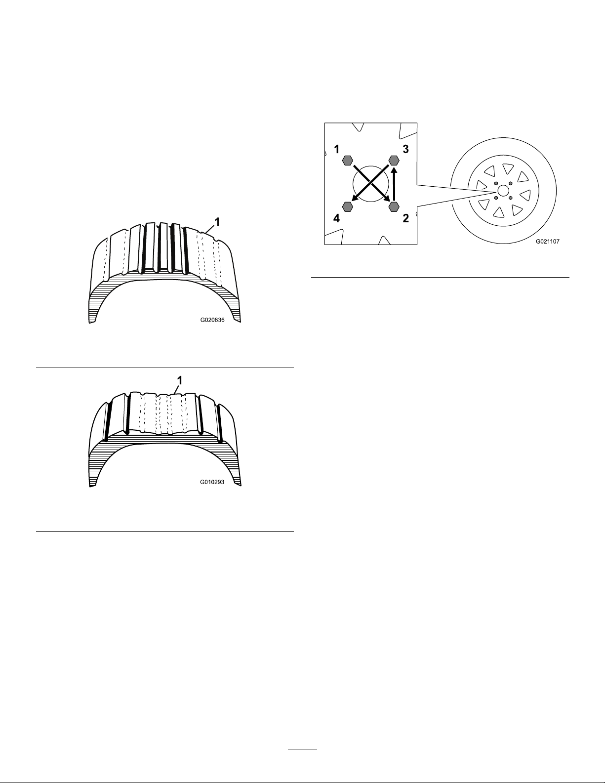
1.Visuallyinspectthetiresfordamageandwear(Figure
13andFigure14).
3.Ensurethatthewheellugnutsaretorquedto108to
122N∙m(80to90ft-lb).
Note:Checkthetorqueofthewheellugnutsinitially
andaftertowing.
Note:Torquethelugnutsinthesequenceshownin
Figure15.
Figure15
Figure13
1.Exampleoftirewearcausedbyunderination
Figure14
1.Exampleoftirewearcausedbyoverination
2.Ensurethatthetiresareinatedtoamaximumof241
kPa(35psi).
Important:Alwayschecktheinformation
ontheactualtiresforthecorrectairpressure
requirement.
Important:Themostcommoncauseoftire
troubleisunderination.Maintainfullair
pressure.
14
Page 15
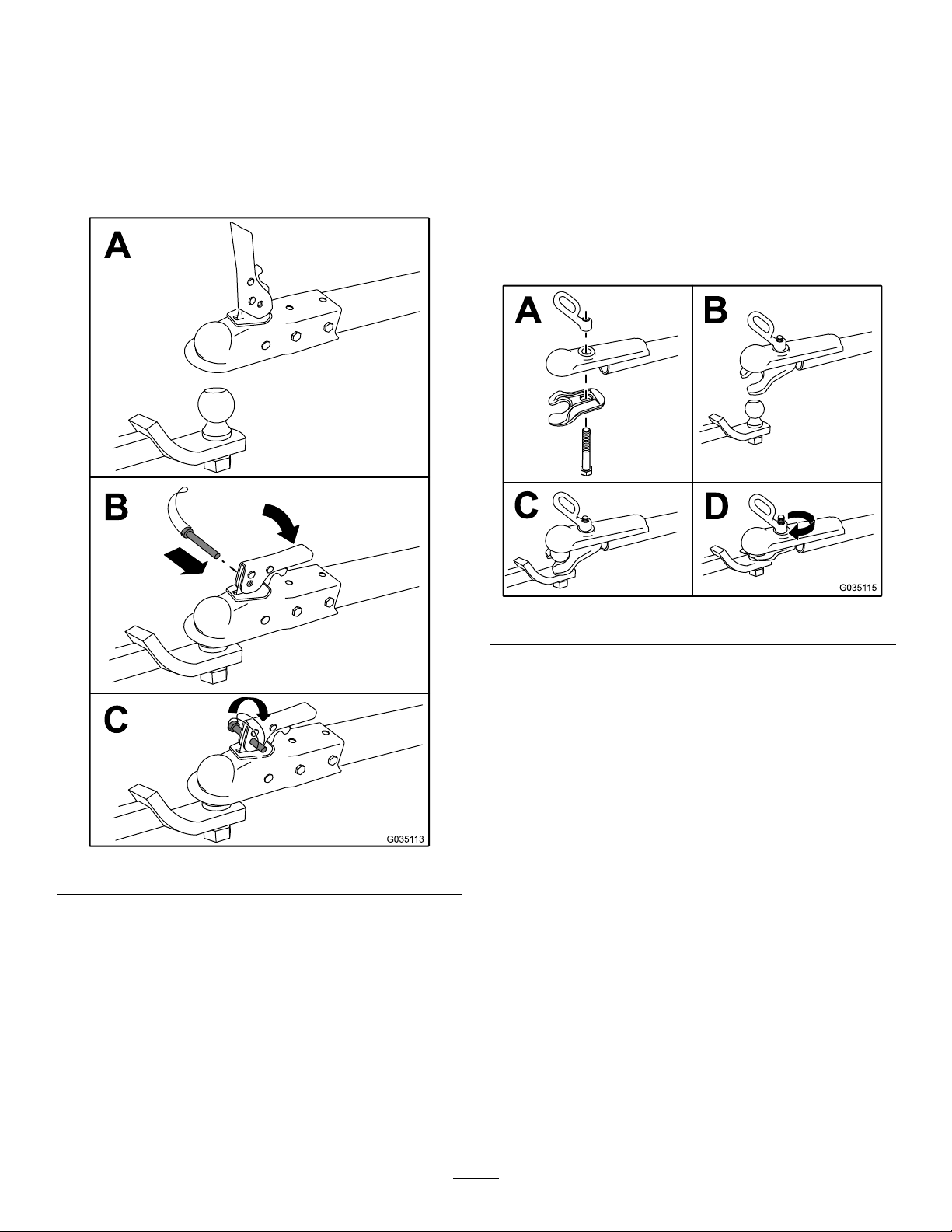
HitchingaMachinewithaStampedBall
Coupler
HitchingaMachinewithaForgedBall
Coupler
1.Applychassisgreasetothesocketofthecouplerand
theareaoftheclampthatcontactstheball.
2.Oilthepivotpointsandslidingsurfacesofthecoupler
withSAE30motoroil.
3.HitchthemachineasshowninFigure16.
1.Applyremovablethread-lockingcompoundtothe
threadsofthecouplerbolttopreventthecoupler
handlefromcomingloose.
Important:Applythread-lockingcompoundas
neededinthefuture.
2.Applychassisgreasetothesocketofthecouplerand
theareaoftheclampthatcontactstheball.
3.InstallhitchthemachineasshowninFigure17.
Figure16
4.Ifthemachineisequippedwithatrailer-lightkit,
connectthewireplugofthetowvehicletothewire
plugofthemachine.
Figure17
Note:Useawrenchtokeeptheboltfromspinning.
4.Ifthemachineisequippedwithatrailer-lightkit,
connectthewireplugofthetowvehicletothewire
plugofthemachine.
15
Page 16
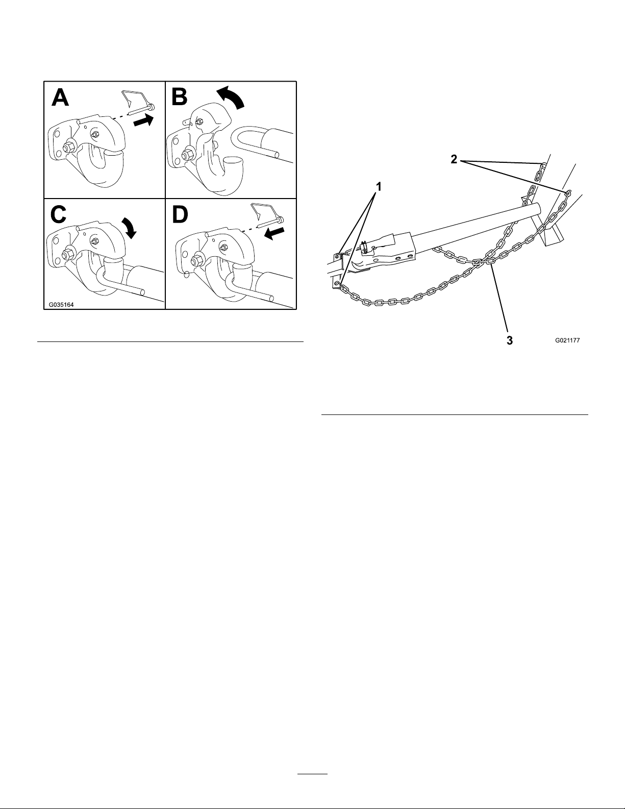
HitchingaMachinewithaPintleHitch
1
2
3
G021 177
Coupler
ConnectingtheSafetyChainstothe
TowVehicle
1.HitchthemachineasshowninFigure18.
Figure18
2.Ifthemachineisequippedwithatrailer-lightkit,
connectthewireplugofthetowvehicletothewire
plugofthemachine.
1.Pullthesafetychainthroughtheslotsinthekeyholes,
sothatthelengthsoneachsideareequal.
2.Crossbothlengthsofchainunderthetowpole.
Note:Crossingthechainsdecreasesthechancesof
thefrontofthemachinedroppingtothegroundifthe
hitchdoesnotholdtheconnection.
Figure19
1.Connectinglinks3.Chaincrossedundertow
pole
2.Keyholesinfrontpost
3.Connecteachlengthofchaintothesafetychain
mountingpointonthetowvehiclewiththeconnecting
links(Figure20).
Important:Ensurethatthechainhasenough
slackforturningaroundcornerswhentowingthe
machine.
Note:Stowtheexcesschaininsidethebottomofthe
frontpostbypushingitintothekeyholesandlatching
theappropriatelinksintothekeyholeslots.
16
Page 17
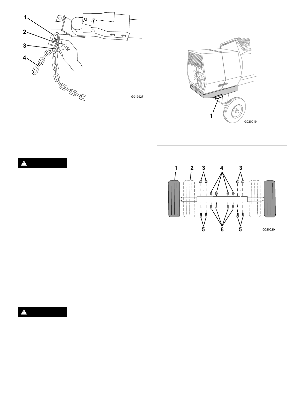
1
2
3
4
G019927
Figure20
G020019
1
1 2
3
4
3
5
6
5
G020020
1.Connectinglink3.Chainlink
2.Safetychainmounting
pointontowvehicle
4.Chain
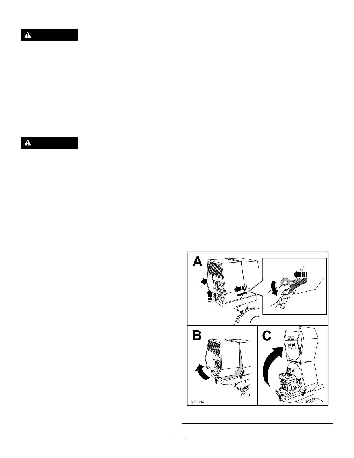
2.Liftthemachineuntilthetiresareofftheground.
3.Useajackstandateachsupportpointontherear
frameextension(Figure21).
Figure21
1.Supportpoint(2)
ExtendingtheAxle
WARNING
Themachineisnotstabletowedwiththeaxlein
thenarrowposition.
Towthemachinewiththeaxleinthewideposition.
Important:Adjusttheaxletothenarrowpositiononly
tomovethemachinethroughanarrowaccesspoint,
suchasthegateofafenceorthedoorwayofabuilding .
PreparingtoChangetheAxleWidth
1.Movethemachinetoalevelsurface.
2.Disconnectthemachinefromthetowvehicle.
3.Securethemachinefrommovement.
4.Ensurethatthedrumisemptyandinthemixposition
(upright).
5.Ensurethatthedrumlatchisengagedandthatthe
drumdoesnotrotatetowardthedumpposition.
4.Removetheboltsandnutsthatsecuretheinneraxleto
theouteraxle(Figure22).
Figure22
1.Wideposition(towing)
2.Narrowposition5.Bolt—wideposition
3.Nut—wideposition6.Bolt—narrowposition
4.Nut—narrowposition
5.Aligntheinneraxletothedesiredpositionasfollows:
•Slideeachsideoftheaxleinwardtothenarrow
position(Figure22).
AdjustingtheAxleWidth
WARNING
Mechanicalorhydraulicjacksmayfailtosupport
themachineandcauseseriousinjury.
Usejackstandswhensupportingthemachine.
1.Alignajackwithanadequateliftheightandweight
capacityundertheaxle;refertoSpecications(page
13).
•Slideeachsideoftheaxleoutwardtothewide
(tow)position(Figure22).
6.Aligntheholesoftheinneraxlewiththeholesofthe
outeraxle.
7.Inserttheboltsthroughtheaxleholes(Figure22).
8.Threadthenutsontothebolts,andtorquethenuts
to87N∙m(64ft-lb).
17
Page 18
TowingtheMachine
WARNING
Towingthemachineathighspeedincreasesthe
riskofahitchmalfunctionandtirefailure.Higher
speedsalsoincreasethemomentumofthemachine
andbrakingdistance.Ifthemachinebecomes
detachedfromthetowvehicleathighspeed,it
couldcausedamagetoproperty,orinjuryordeath
tobystanders.
Donotexceed88km/h(55mph)whentowingthe
machine.Forpoorroadconditionsorinclement
weather,reducespeedaccordingly.
WARNING
Towingthemachinewithmaterialinthedrum
increasestheriskofahitchmalfunctionandtire
failure.Inaddition,materialcouldbounceoutof
thedrumandhitothervehiclesand/orpeople.
Materialinthedrumincreasestheweight,which
affectsmomentumandbrakingdistance.
Donottowthemachinewithmaterialinthedrum.
PreparingtoUsetheMachine
•Reviewallofthesafetydecalsonthemachine.
•Useahard-hat,hearingprotection,ashirtwithlong
sleevesthataretightatthewrists,tight-ttinggloves
withoutdrawstringsorloosecuffs,eyeprotection,and
adustmaskorrespirator.Ameshvisoralonedoes
notprovidesufcienteyeprotection;supplementwith
protectiveglasses.
•Ensurethatyouarefamiliarwithsafetyregulationsand
shutdownproceduresdescribedinthisOperator’sManual
andtheEngineOwner’ sManual.
•Ensurethatallguardsareinplaceandingoodcondition.
•Ensurethatthepaddlesareinplaceandingood
condition.
•Checkthefuelandoillevelsoftheengine.
•Whenpreparingtomixmaterial:
1.Movethemachinetoaleveljob-sitesurface.
2.Removethemachinefromthetowvehicle.
3.Securethemachinefrommovementbeforeyou
useit.
4.Ensurethatthedrumisinthemixposition
(upright).
5.Ensurethatthedrumlatchisengagedandthatthe
drumdoesnotrotatetowardthedumpposition.
•ReviewandunderstandSafeOperatingPractices(page4).
•Testthebrakesofthetowvehiclebeforetowing.
•Avoidsuddenstartsandstopswhiletowingthemachine.
OpeningandClosingtheCowl
OpeningtheCowl
Figure23
18
Page 19
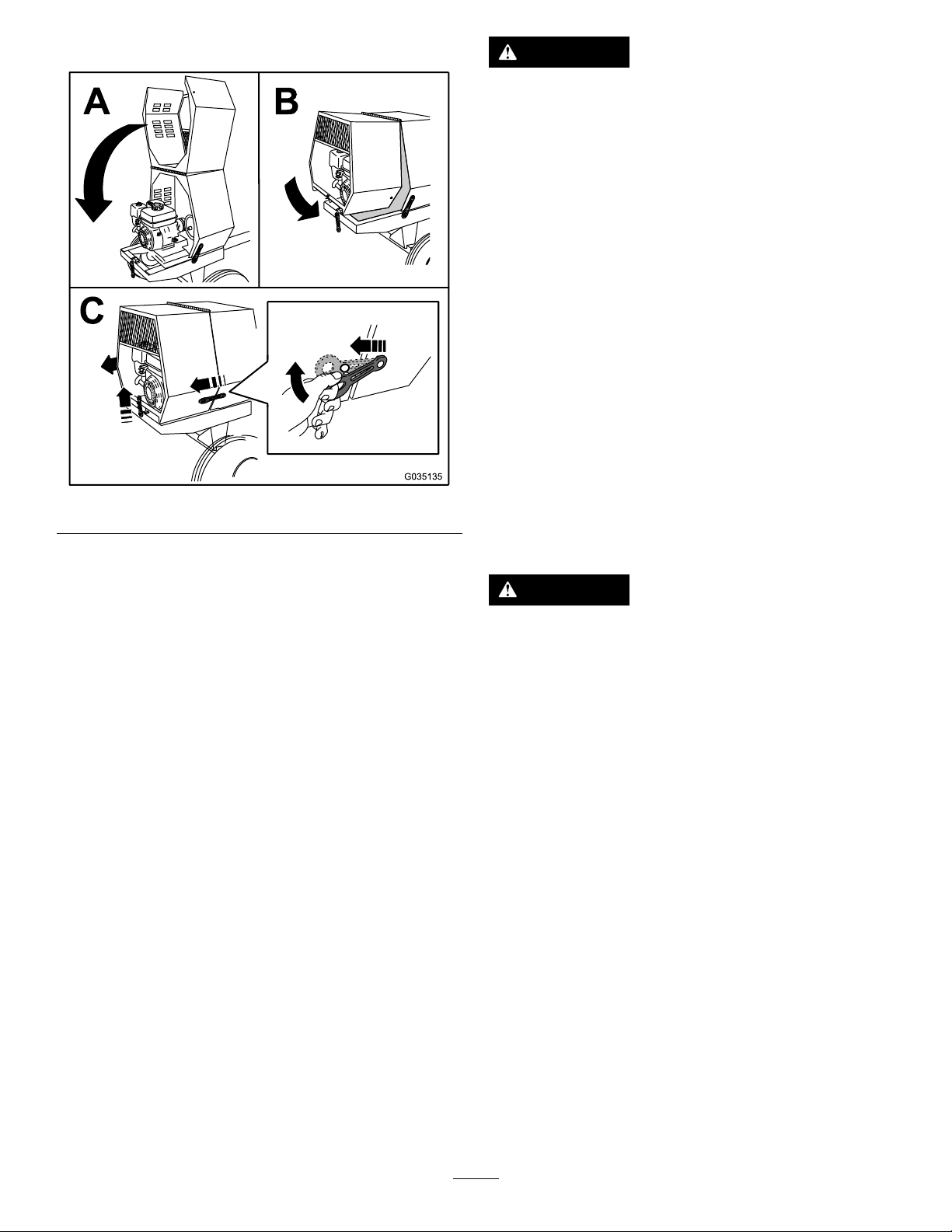
ClosingtheCowl
Figure24
DANGER
Incertainconditions,fuelisextremelyammable
andhighlyexplosive.Areorexplosionfromfuel
canburnyouandothersandcandamageproperty.
•Fillthefueltankoutdoors,inanopenarea,
whentheengineiscold.Wipeupanygasoline
thatspills.
•Neverllthefueltankinsideanenclosedtrailer.
•Donotllthefueltankcompletelyfull.Add
fueltothefueltankuntilthelevelis6to13mm
(1/4to1/2inch)belowthebottomoftheller
neck.Thisemptyspaceinthetankallowsfuel
toexpand.
•Neversmokewhenhandlingfuelandstayaway
fromanopenameorwherefuelfumesmaybe
ignitedbyaspark.
•Storefuelinanapprovedcontainerandkeepit
outofthereachofchildren.Neverbuymore
thana30-daysupplyoffuel.
•Donotoperatewithoutentireexhaustsystemin
placeandinproperworkingcondition.
AddingFuel
•Forbestresults,useonlyclean,fresh(lessthan30days
old),unleadedgasolinewithanoctaneratingof87or
higher((R+M)/2ratingmethod).
•Ethanol:Gasolinewithupto10%ethanol(gasohol)
or15%MTBE(methyltertiarybutylether)byvolume
isacceptable.EthanolandMTBEarenotthesame.
Gasolinewith15%ethanol(E15)byvolumeisnot
approvedforuse.Neverusegasolinethatcontains
morethan10%ethanolbyvolume,suchasE15
(contains15%ethanol),E20(contains20%ethanol),or
E85(containsupto85%ethanol).Usingunapproved
gasolinemaycauseperformanceproblemsand/orengine
damagewhichmaynotbecoveredunderwarranty.
•Donotusegasolinecontainingmethanol.
•Donotstorefueleitherinthefueltankorfuelcontainers
overthewinterunlessafuelstabilizerisused.
•Donotaddoiltogasoline.
DANGER
Incertainconditionsduringfueling,static
electricitycanbereleased,causingasparkthat
canignitethegasolinevapors.Areorexplosion
fromfuelcanburnyouandothersandcandamage
property.
•Alwaysplacefuelcontainersonthegroundaway
fromyourvehiclebeforelling.
•Donotllfuelcontainersinsideavehicleoron
atruckortrailerbed,becauseinteriorcarpets
orplastictruckbedlinersmayinsulatethe
containerandslowthelossofanystaticcharge.
•Whenpractical,removeequipmentfromthe
truckortrailerandrefueltheequipmentwithits
wheelsontheground.
•Ifthisisnotpossible,thenrefuelsuchequipment
onatruckortrailerfromaportablecontainer,
ratherthanfromafuel-dispensernozzle.
•Ifyoumustuseafuel-dispensernozzle,keepthe
nozzleincontactwiththerimofthefueltank
orcontaineropeningatalltimesuntilfuelingis
complete.
19
Page 20
WARNING
1
G019799
Fuelisharmfulorfatalifswallowed.Long-term
exposuretovaporscancauseseriousinjuryand
illness.
FillingtheFuelT ank
Capacity:5.3L(1.4USgallons)
1.Parkthemachineonalevelsurface,shutofftheengine,
andallowtheenginetocool.
•Avoidprolongedbreathingofvapors.
•Keepfaceawayfromnozzleandfueltankor
conditionerbottleopening.
•Avoidcontactwithskin;washoffspillswith
soapandwater.
UsingStabilizer/Conditioner
Useafuelstabilizer/conditionerinthemachinetoprovide
thefollowingbenets:
•Keepsfuelfreshduringstorageof90daysorless.For
longerstorageitisrecommendedthatthefueltankbe
drained.
•Cleanstheenginewhileitruns
•Eliminatesgum-likevarnishbuildupinthefuelsystem,
whichcauseshardstarting
Important:Donotusefueladditivescontaining
methanolorethanol.
Addthecorrectamountoffuelstabilizer/conditioner
tothefuel.
Note:Afuelstabilizer/conditionerismosteffective
whenmixedwithfreshfuel.Tominimizethechanceof
varnishdepositsinthefuelsystem,usefuelstabilizerat
alltimes.
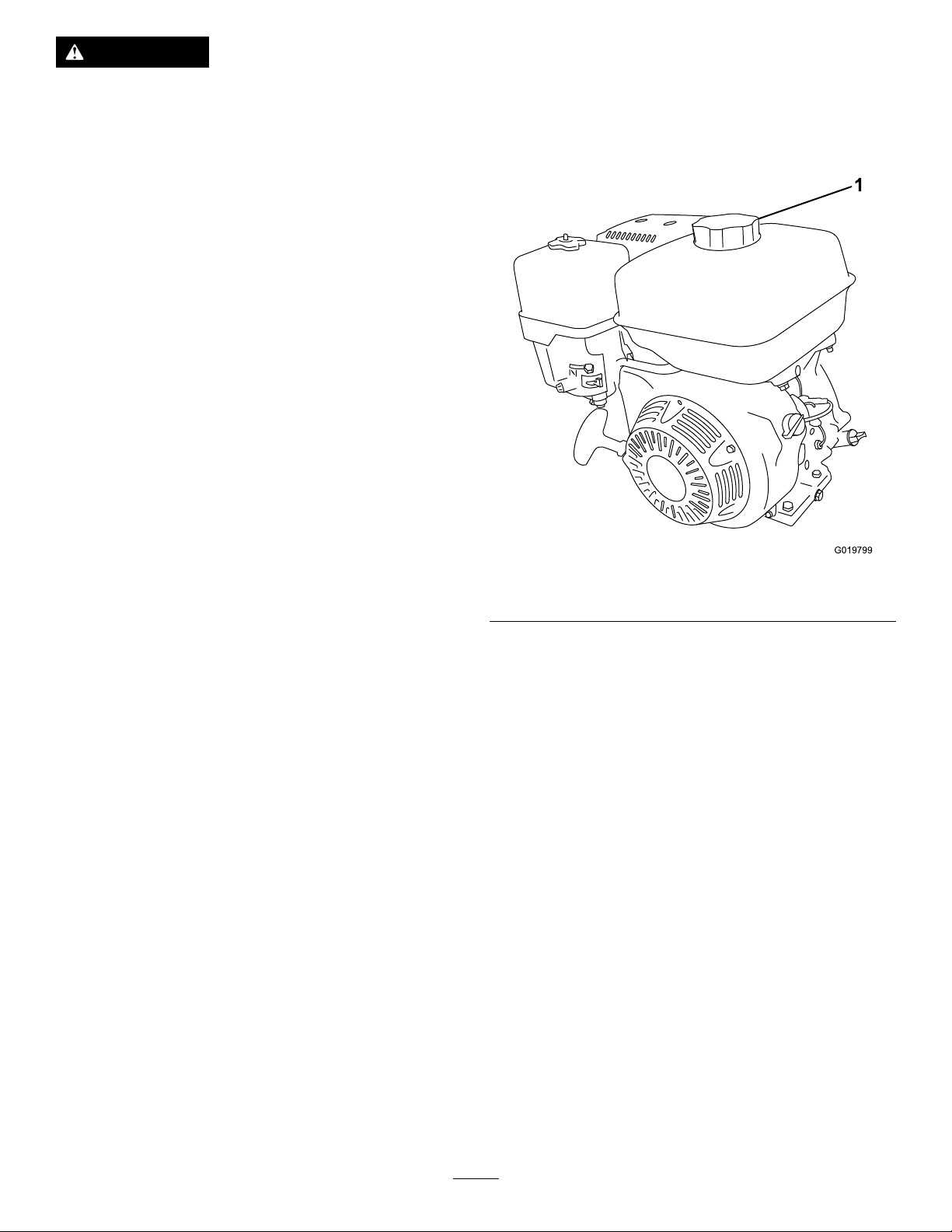
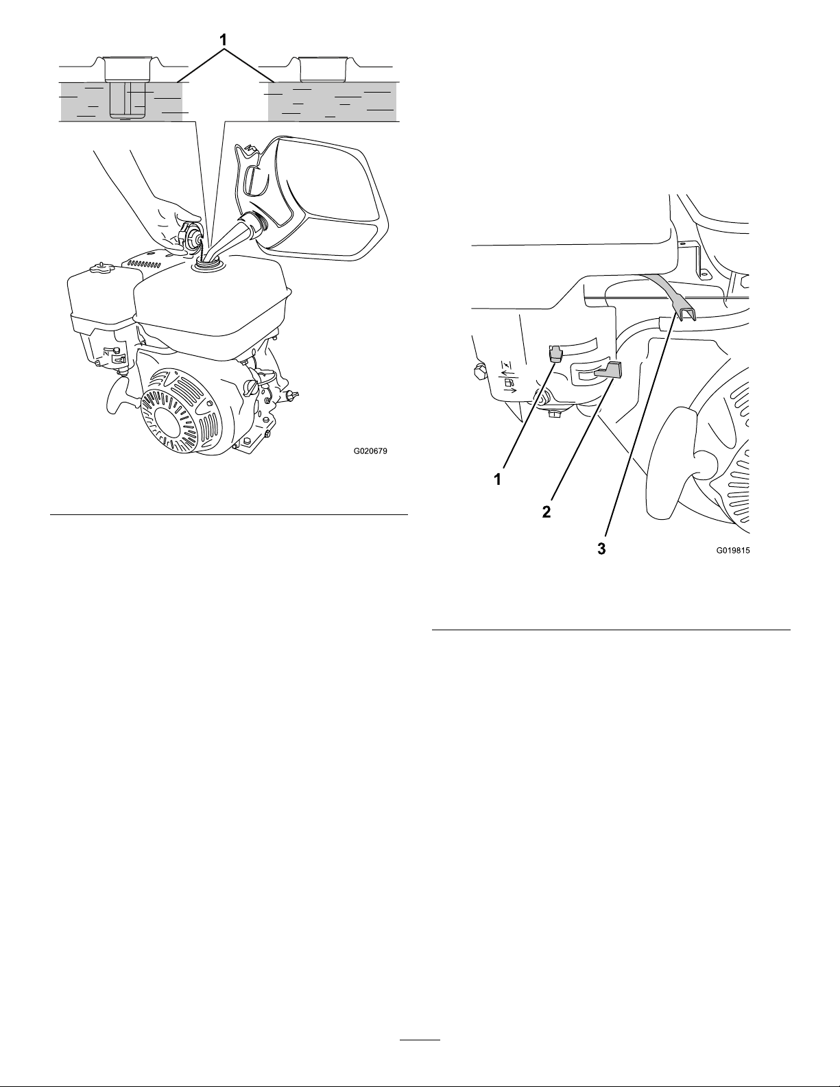
2.Cleanaroundthefuelcapandremoveit(Figure25).
Figure25
1.Fuelcap
3.Addfueltothefueltank,untilthelevelisatthebottom
ofthemaximumfuellevel,asshowninFigure26.
Important:Thisspaceinthetankallowsthefuel
toexpand.Donotllthefueltankcompletelyfull.
20
Page 21
G020679
1
StartingandShuttingOffthe
G019815
1
2
3
Engine
StartingtheEngine
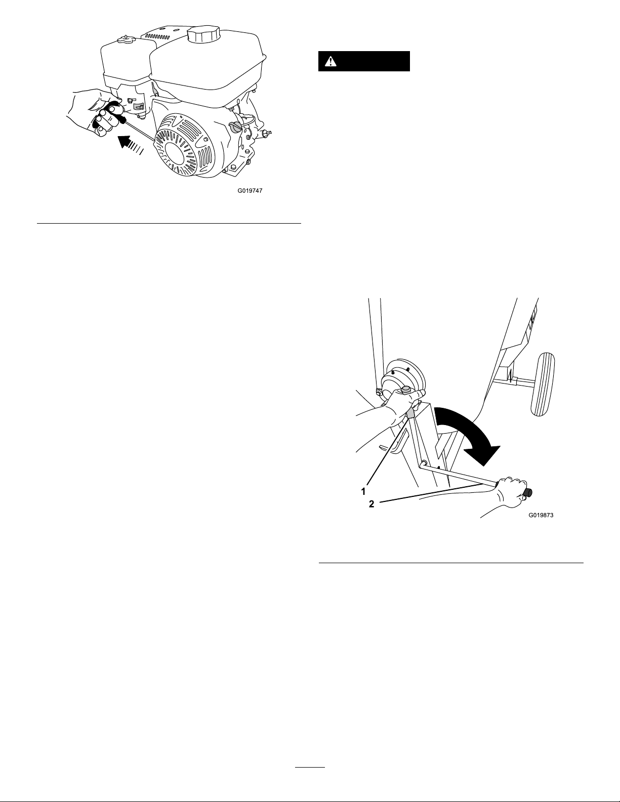
1.Ontheengine,movethethrottleleverawayfromthe
MINposition,1/3ofthewaytowardtheMAXposition
(Figure27).
Figure26
1.Maximumfuellevel
4.Installthefuelcapsecurely(Figure25).
5.Wipeupanyfuelthatmayhavespilled.
CheckingtheEngine-OilLevel
Beforeyoustarttheengineandusethemachine,check
theoillevelintheenginecrankcase;refertoCheckingthe
Engine-OilLevel(page30).
Figure27
1.Chokelever
2.Fuelvalve
2.MovetheleverofthefuelvalvetotheONposition,all
thewaytotheright(Figure27).
3.Positionthechokeleverasfollows:
3.Throttlelever
•Tostartacoldengine,movethechokelevertothe
CLOSEDposition,allthewaytotheleft(Figure27).
•Tostartawarmengine,movethechokeleverin
theOPENposition,allthewaytotheright.
4.RotatetheengineswitchtotheONposition(Figure
27).
5.Pulltherecoil-starthandlelightlyuntilyoufeel
resistance,thenpullthehandlebriskly .Returnthe
recoil-starthandlegently(Figure28).
21
Page 22
G019747
ControllingthePaddles
G019873
1
2
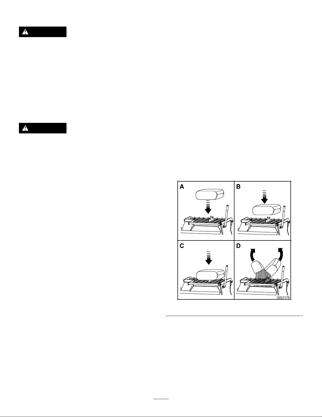
DANGER
Thismachineiscapableofamputatinghands.
•Stayintheoperator’spositionwhilethemachine
isrunning.
•Keepallbystandersasafedistancefromthe
machine.
•Stopthemachineimmediatelyifanypeopleor
animalsentertheworkarea.
Figure28
Note:IfthechokeleverissettotheCLOSEDpositionto
starttheengine,graduallymovethechokeleverbacktoward
theOPENpositionastheenginewarmsup.Iftheenginestalls
orhesitates,movethechokeleverbacktowardtheCLOSED
positionuntiltheenginerunssmooth.Allowtheengineto
warmup,thenmovethechokelevertotheOPENposition.
ShuttingOfftheEngine
Important:Duringnormaloperation,iftheengine
hasbeenworkinghardorishot,letitidleforaminute
beforeshuttingofftheengine.Thishelpstocoolthe
enginebeforestopping .
1.EnsurethatthechokeleverisintheOFFposition
(Figure27).
2.MovethethrottlelevertotheMINposition(Figure27).
3.RotatetheengineswitchtotheOFFposition.
•Neverplaceanypartofyourbodyintoaposition
thatcausesanunsafeoperatingcondition.
Important:Ensurethatthepaddlesdonotturnwhen
clutchisintheOFFposition.
Usetheclutchlevertocontrolthepowertransmissiontothe
paddlesofthemachine.
Figure29
1.Offposition2.Onposition
22
Page 23
MixingtheMaterial
A
B
D
G021 179
DANGER
Eyeandskincontactwithconcretematerialsand
breathingthedustinvolvedishazardoustoyour
health.
•Ensurethatthereisadequateairventilation.
•Wearadustmasktopreventinhalationofdust
whileusingthemachine;refertoSafeOperating
Practices(page4).
•Avoiddirectcontactofcementandconcrete
materialswithskinandeyes.
DANGER
Contactwiththemixingpaddlescouldcause
damageorinjury.
Neverputyourhandsortoolsinsidethedrumwhile
theengineisrunning.
Important:Donotaddmorematerialthanthebatch
capacityofthemachine;refertoSpecications(page13).
MixingaBatchofMaterialinthe
Machine
1.Ensurethatthereisnoold,loosematerialinthedrum
thatcancontaminatethebatchofmaterial;referto
CleaningtheDrum(page24)andDumpingtheDrum
(page24),thenreturnthedrumtotheuprightposition.
Note:Ensurethatthedrumisinthemixposition
(upright)andthedrumlatchisengaged.
2.MovetheclutchlevertotheOFFposition.
3.Starttheengine.
Note:Allowtheenginetowarmupat2/3throttle
for1to2minutes.
4.SetthethrottleleverontheenginetotheMAXposition.
5.MovetheclutchlevertotheONposition.
6.Addtheingredientsforthebatchasfollows:
A.Pourwaterintothedrumthroughthegrate.
B.Addtheplaster,cement,orotherbindingmaterial.
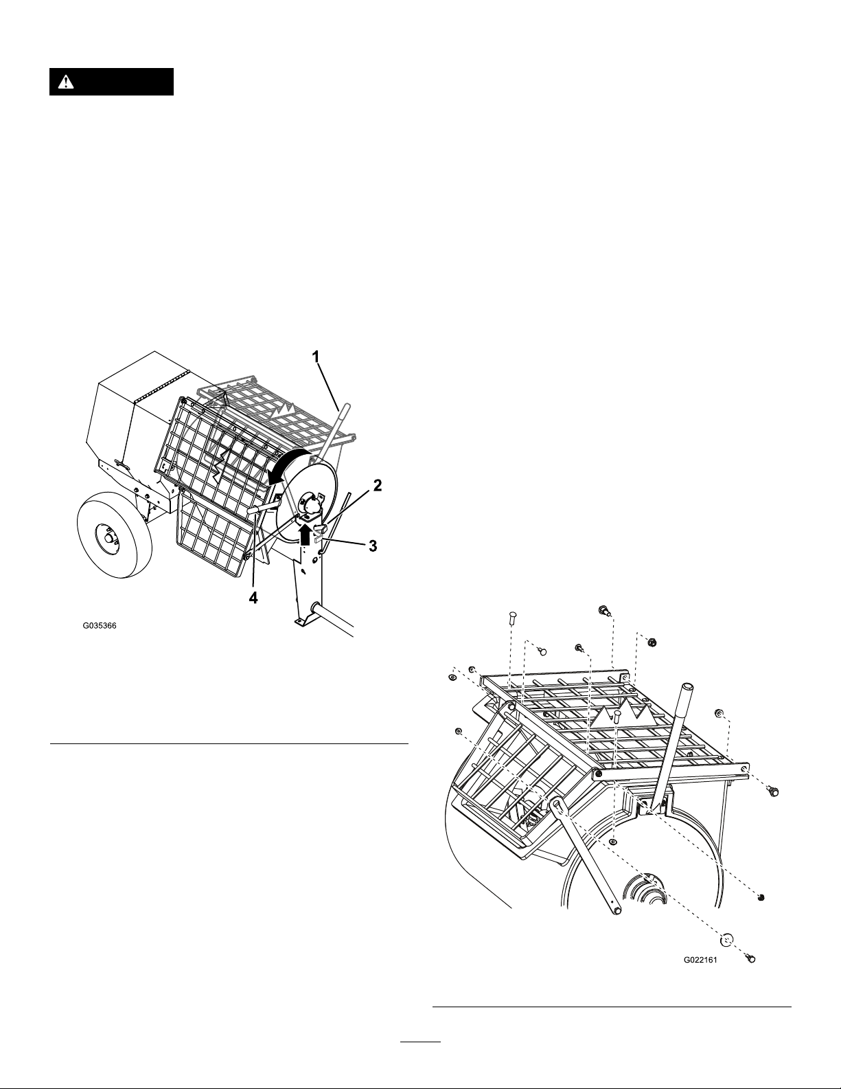
Note:Youcanopenbagsofcement,plaster,and
bindingmaterialsbyloweringthebagontothe
bagsplitter(Figure30).
Note:Followthemanufacturer’sinstructionsthatareprinted
onthepackagingoftheproductyouareusing.
Figure30
C.Ifyouareusingsandand/orotherreinforcing
materials,addthemintothedrum.
7.Allowthepaddlestomixthematerialuntilthe
ingredientshaveauniformappearance.
Note:Ifneeded,addwaterorplaster,cement,or
otherbindingmaterialuntiltheconsistencyofthe
batchiscorrect.
8.Releasethedrumlatchanddumpthedrum;referto
DumpingtheDrum(page24).
23
Page 24
UsingtheDrum
G022161
DANGER
Note:Thisstepcleansthepaddlesanddrumbetween
batchesandpreventsdriedmaterialfromformingand
contaminatingthenextbatchofmaterial.
Contactwiththemixingpaddlescouldcause
damageorinjury.
Neverputyourhandsinsidethedrumwhilethe
engineisrunning.
DumpingtheDrum
Note:Whendumpingabatchofmaterial,leavetheengine
runningandtheclutchintheONpositionsotherotating
paddleshelpdischargethematerial.
1.Alignawheelbarroworsimilarcontainerofadequate
capacityinthepathofthedrumopening.
2.Graspthedumphandlewithyourlefthand(Figure31).
CleaningtheDrum
Important:Donotstrikeonthedrumwithashovel,
hammer,oranyotherdevicetoloosenanyaccumulated
driedmaterials.
1.Stoptherotationofthepaddlesbymovingtheclutch
levertotheOFFposition.
2.RotatetheengineOn/OffswitchtotheOFFposition.
3.Ensurethatthedrumisinthemixposition(upright).
4.Spraythemachinewithwatertoremoveany
accumulatedmaterial.
5.Starttheengine.
6.Starttherotationofthepaddlesbymovingtheclutch
levertotheONposition.
7.Dumpthedrum.
AdjustingthePaddleBlades
Note:Adjustingthepaddlebladesisoptional.
1.Shutofftheengineandwaitforallmovingpartsto
stop.
Figure31
1.Dumphandle—Mix
position
2.Drumlatch—Release
position
Note:Whendumpingabatchofmaterial,aligna
wheelbarroworasimilarcontainerofadequatecapacity
beneaththechute.
3.Liftthehandleofthedrumlatch(Figure31).
4.Withbothhandsonthedumphandle,rotateit
counterclockwisetodischargethecontentsofthe
drum(Figure31).
Note:Allowthemachinetocompletelydischargethe
contentsofthedrum.
3.Drumlatch—Locked
position
4.Dumphandle—Dump
position
2.Disconnectthewirefromthesparkplug;referto
DisconnectingtheSpark-PlugWire(page27).
3.Removethenutsandboltsthatsecurethegratetothe
drum,andremovethegrate(Figure32).
5.Rotatethedumphandleclockwiseuntilthedrum
latchlocksthedrumintheuprightposition(Figure31).
6.Afterdischargingabatchofmaterial,cleanthedrum;
refertoCleaningtheDrum(page24).
Figure32
24
Page 25
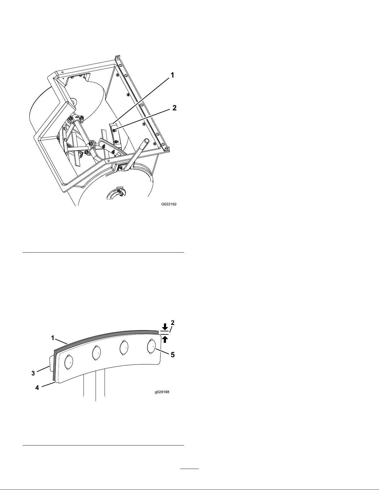
4.Loosenthenutsandboltsthatsecurethepaddleblades
1
2
G022162
tothepaddles(Figure33).
Note:Ifnecessary,tipthedrumtothedumpposition
toaccessthepaddles.
6.Installthegratewiththenutsandboltsthatyou
removedinstep3andtightenthenutsandboltsuntil
theyaresecure.
Figure33
1.Paddleblade2.Nutandbolt
5.Adjusttherubberwiperstobeclosetothedrumwall
andpositionthemetalpaddlebladessothattheouter
edgeis3to6mm(1/8to1/4inch)fromtheouter
edgeofthewipers(Figure34).Tightenthenutsand
boltstosecurethebladestothepaddles.
Note:EnsurethattheclutchleverisintheOFF
positionandrotatethepaddlesasneeded.
Figure34
1.Wiper4.Paddleblade
2.3to6mm(1/8to1/4inch)5.Carriagebolt
3.Wiperbar
25
Page 26

Maintenance
Important:Beforeperforminganymaintenanceprocedures,rstshutofftheengine,wait5minutestoallowall
movingpartstocometoacompletestopandcool,anddisconnectthespark-plugwire.
RecommendedMaintenanceSchedule(s)
MaintenanceService
Interval
Aftertherst25hours
Beforeeachuseordaily
Aftereachuse
Every40hours
Every50hours
Every100hours
Every300hours
Monthly
MaintenanceProcedure
•Changetheengineoil.
•Inspectthebeltsandadjustasnecessary.
•Inspectthetiresandwheels.
•Inspecttheair-cleanerelements.
•Checktheengine-oillevel.
•T orquethelugnutsto108to122N∙m(80to90ft-lb)aftertowing.
•Cleanthedrumbetweenmixingbatchesofmaterial.
•Lubricatethetrunnions.
•Inspectthebeltsandadjustasnecessary.
•Checktheclutchoperation
•Cleantheair-cleanerelements.Cleanthemmorefrequentlyindustyoperating
conditions.
•Changetheengineoil.
•Checkthesparkplug.
•Cleanthesparkarrester.
•Cleanthefuel-sedimentcup.
•Replacethepaperair-cleanerelement.Replaceitmorefrequentlyindusty
operatingconditions.
•Replacethesparkplug.
•Lubricatethepillow-blockbearings.
Yearlyorbeforestorage
Every2years
•Cleanthefuel-sedimentcup.
•Replacethebelts.
Important:Refertoyourengineowner’smanualforadditionalmaintenanceprocedures.
26
Page 27
Premaintenance
G019281
1
G020752
G020753
Procedures
PreparingtheMachinefor Maintenance
1.Parkthemachineonalevelsurface.
2.Removethemachinefromthetowvehicle.
3.Securethemachinefrommovement.
4.Opentherearcowl;refertoOpeningtheCowl(page
18).
5.Ensurethattheengineandmuferarecool.
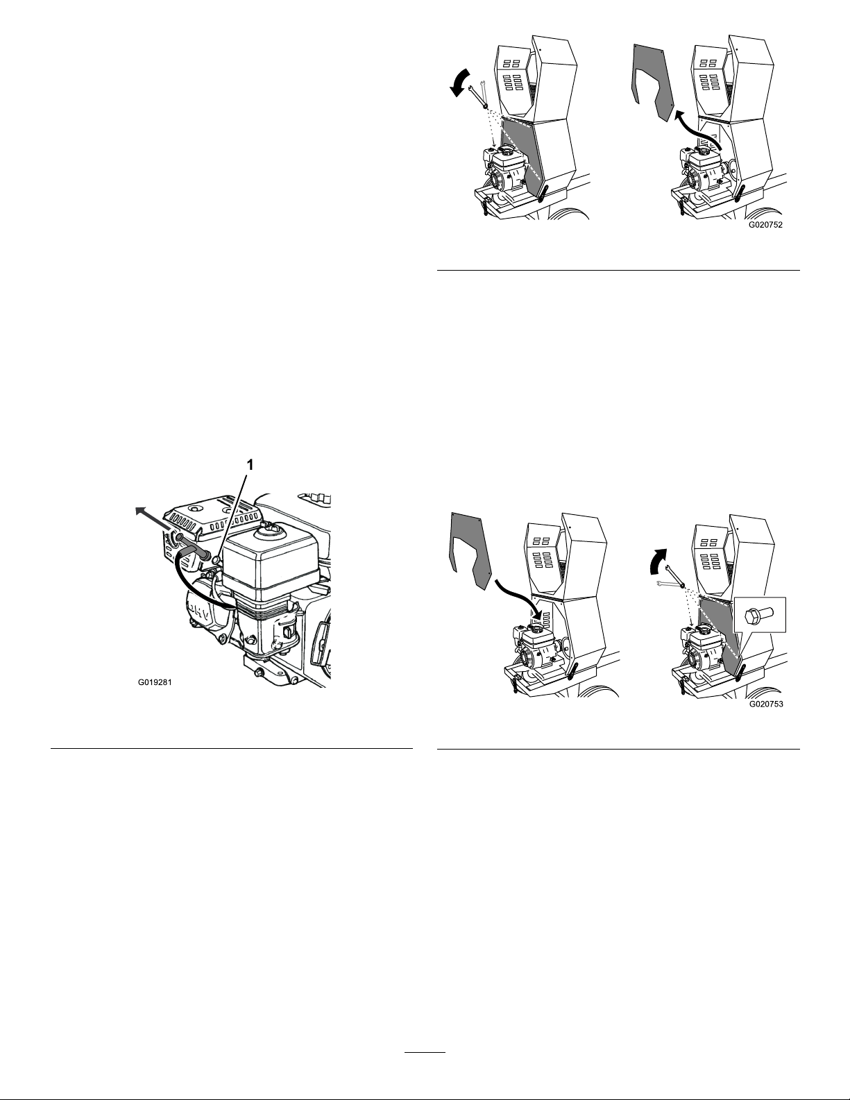
6.Disconnectthespark-plugwire;refertoFigure35.
DisconnectingtheSpark-Plug Wire
Pullthespark-plugwireofftheterminalofthesparkplug
(Figure35).
Figure36
3.Toremovethedividerplate,liftitupwardandrotate
itcounterclockwisesothatitclearsvariousengine
components.
InstallingtheDividerPlate
1.Guidethedividerplateintopositionagainstthefront
cowl.
Note:Startwiththedividerplaterotatedslightly
counterclockwise,andthenrotateitclockwisewhile
loweringitintoposition.
Ensurethatthedividerplateisnotbackward.
Figure35
1.Sparkplug
RemovingandInstallingthe DividerPlate
Youneedtoremovethedividerplatetoprovideaccessbefore
performingsomemaintenanceprocedures.
RemovingtheDividerPlate
1.Unlatchandopenthecowl;refertoOpeningtheCowl
(page18).
2.Useawrenchtoremovethe4boltsthatsecurethe
dividerplatetothefrontcowl.
Note:Retaintheboltsforinstallingthedividerplate.
Figure37
2.Aligntheboltholesinthedividerplateandthefront
cowl.
3.Installthe4boltsandhand-tightenthemtoprevent
cross-threading.
4.Tightentheboltswithawrenchuntiltheyaresecure.
27
Page 28
Lubrication
2
3
G020684
1
3
G020685
LubricatingtheBearingsand Seals
ServiceInterval:Aftereachuse—Lubricatethetrunnions.
Monthly—Lubricatethepillow-blockbearings.
Note:Thepillow-blockbearingsareinsidethe
cowl—removethedividerplatetoaccessthem;referto
RemovingtheDividerPlate(page27).
GreaseType:general-purposelithiumgrease.
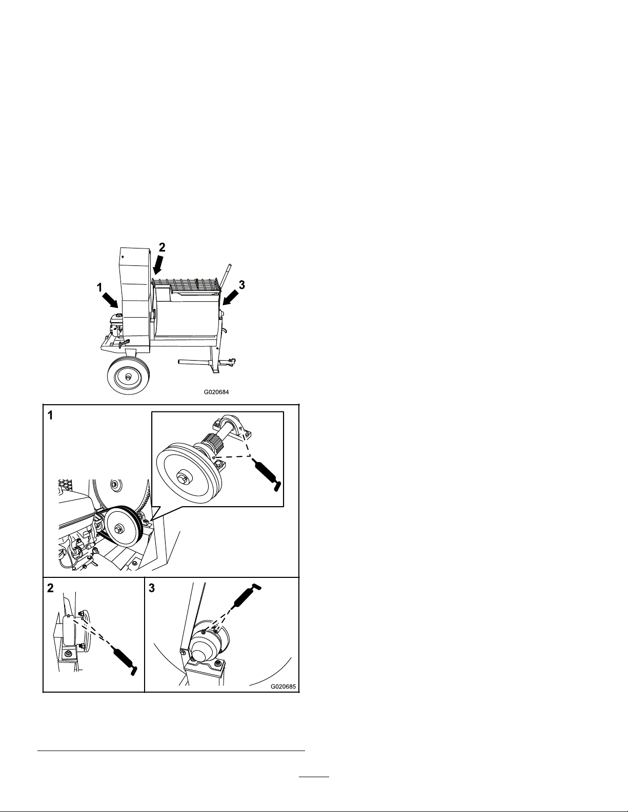
1.Cleanaroundeachgreasettingwitharagandliftthe
plasticcapoffthegreasetting(Figure38).
2.Pumpgreaseintoeachttingasfollows:
•Forthepillow-blockbearings,pump1shotof
greaseintoeachtting(Figure38).
•Forthetrunnions,pumpseveralshotsofgrease
intoeachttinguntilitstartstooozeoutofthe
bearinghousing(Figure38).
Important:Pumpgreaseinslowlyandcarefully
topreventdamagetothebearingseals.
3.Wipeupanyexcessgrease.
Figure38
1.Pillow-blockbearings3.Fronttrunnion
2.Reartrunnion
28
Page 29
EngineMaintenance
G020216
1
2
3
4
5
6
ServicingtheAirCleaner
ServiceInterval:Beforeeachuseordaily—Inspectthe
air-cleanerelements.
Every50hours—Cleantheair-cleanerelements.Clean
themmorefrequentlyindustyoperatingconditions.
Every300hours/Yearly(whichevercomes
rst)—Replacethepaperair-cleanerelement.Replace
itmorefrequentlyindustyoperatingconditions.
Important:Donotoperatetheenginewithoutthe
air-lterassembly;extremeenginedamagewilloccur.
1.Shutofftheengineandwaitforallmovingpartsto
stop.
2.Disconnectthewirefromthesparkplug;referto
DisconnectingtheSpark-PlugWire(page27).
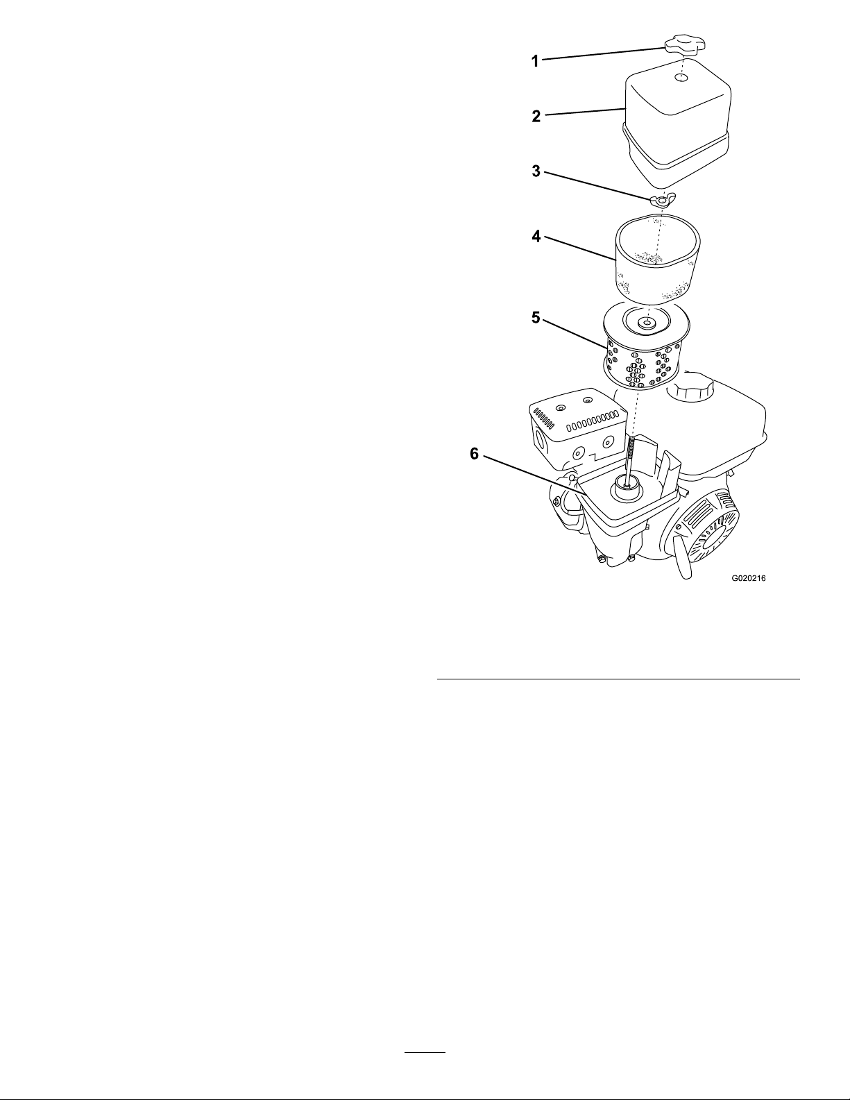
3.Removethenutthatsecuresthecover(Figure39).
Figure39
1.Covernut
2.Cover
3.Wingnut6.Base
4.Removethecover.
Note:Becarefultopreventdirtanddebrisfrom
fallingintothebase.
5.Removethefoamandpaperelementsfromthebase
(Figure39).
6.Removethefoamelementfromthepaperelement
(Figure39).
7.Inspectthefoamandpaperelementsandreplacethem
iftheyaredamagedorexcessivelydirty.
Note:Nevertrytobrushdirtoffthepaperelement;
brushingforcesthedirtintothebers.
8.Cleanthefoamelementinwarm,soapywaterorin
anonammablesolvent.
Note:Donotusefueltocleanthefoamelement
becauseitcouldcreateariskofreorexplosion.
9.Rinseanddrythefoamelementthoroughly.
4.Foamelement
5.Paperelement
29
Page 30
10.Dipthefoamelementincleanengineoil,thensqueeze
g013375
0 20 40 60 80 100 F
-20 -10 0 10 20 30 40 C
o
o
30
5W - 30 / 10W - 30
outtheexcessoil.
Note:Excessoilinthefoamelementrestrictstheair
owthroughtheelementandmayreachthepaper
lterandclogit.
11.Wipedirtfromthebaseandthecoverwithamoistrag.
Note:Becarefultopreventdirtanddebrisfrom
enteringtheairductleadingtothecarburetor.
12.Installtheair-cleanerelementsandensurethattheyare
properlypositioned.
13.Securelyinstallthecoverwiththenut.
ServicingtheEngineOil
ToroPremiumEngineOilisavailablefromyourAuthorized
ToroDealer.
Important:Use4-cycleengineoilthatmeetsorexceeds
therequirementsforAPIservicecategory
or higher
CrankcaseCapacity:1.1L(1.2USqt)
.
SJ , SL, SM,
CheckingtheEngine-OilLevel
ServiceInterval:Beforeeachuseordaily
1.Placethemachineonaat,levelsurface,andshutoff
theengine.
2.Allowtheenginetocool.
3.Cleanaroundthedipstick.
4.ChecktheoillevelasshowninFigure41.
Important:Iftheoillevelinthecrankcaseistoolow
ortoohighandyouruntheengine,youmaydamage
theengine.Thistypeofdamageisnotcoveredbythe
warranty.
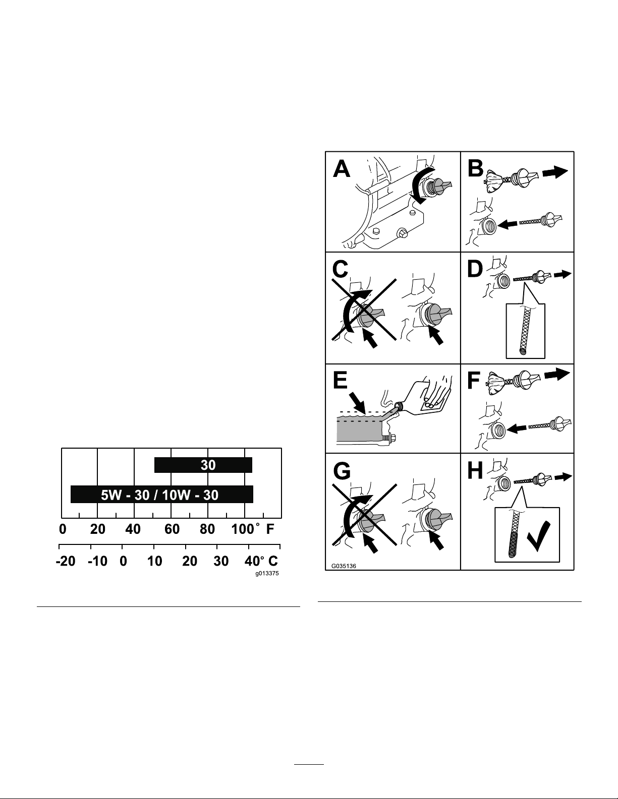
Note:UseSAE10W-30forgeneraluse.Youcanuse
theotherviscositiesshowninthechartwhentheaverage
temperatureinyourareaiswithintheindicatedrange(Figure
40).
Figure40
Figure41
30
Page 31
ChangingtheEngineOil
1
2
3
G019750
1
2
3
4
G019746
ServiceInterval:Aftertherst25hours
Every100hours
WARNING
Oilmaybehotaftertheenginehasbeenrun,and
contactwithhotoilcancauseseverepersonalinjury.
Avoidcontactingthehotengineoilwhenyoudrain
it.
1.Shutofftheengineandwaitforallmovingpartsto
stop.
2.Disconnectthewirefromthesparkplug;referto
DisconnectingtheSpark-PlugWire(page27).
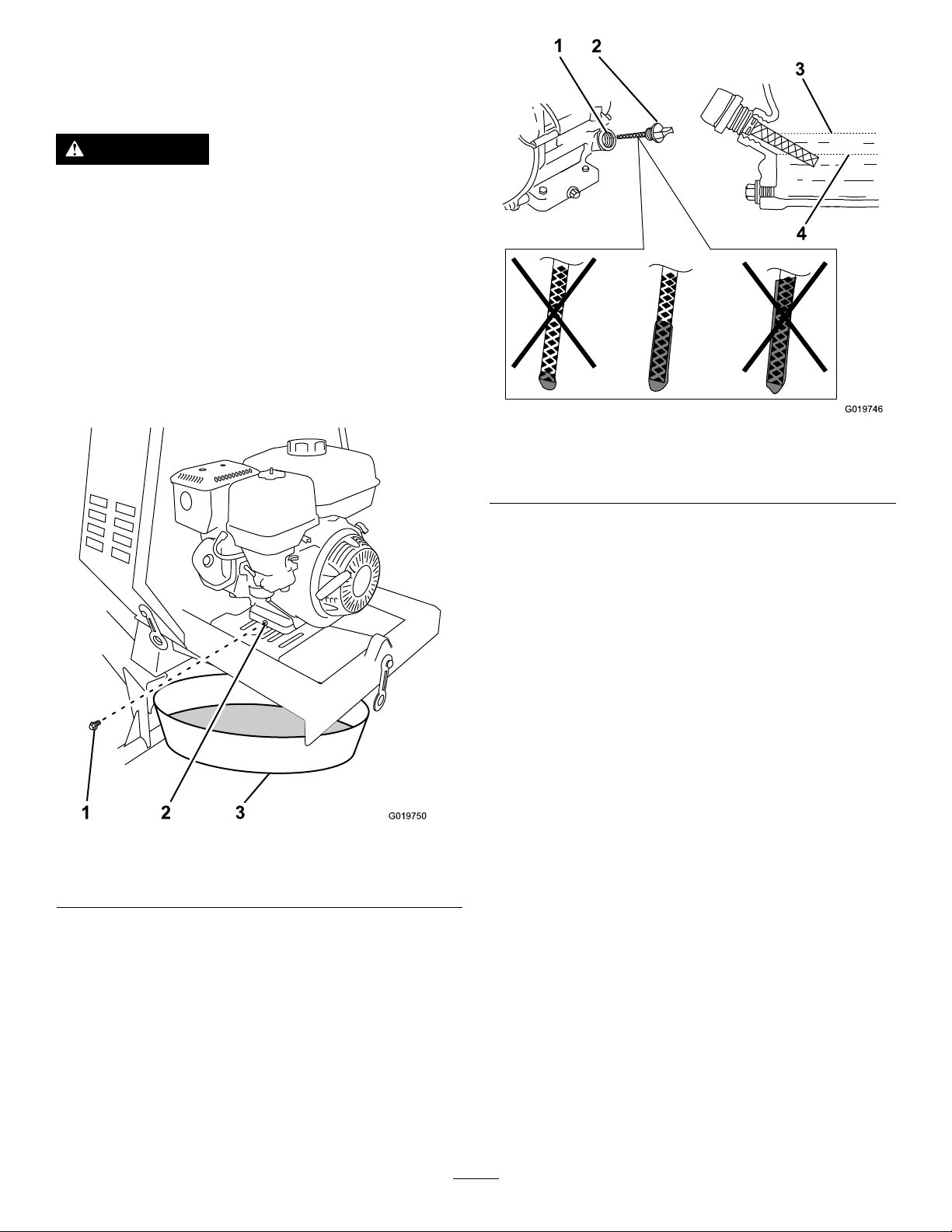
3.Placeadrainpanundertheoil-drainholeoftheengine
(Figure42).
Figure43
1.Oil-llhole3.Oil-levelupperlimit
2.Dipstick
4.Oil-levellowerlimit
Figure42
1.Oil-drainplug3.Oil-drainpan
2.Oil-drainhole
4.Removethedrainplugandcatchtheoilintheoil-drain
pan(Figure42).
5.Whentheoilhasdrainedcompletely,installthedrain
plugwithanewwasher(Figure42).
Note:Disposeoftheusedoilatacertiedrecycling
center.
6.Removethedipstick(Figure43)andslowlypouroil
intothellholeuntiltheoilreachestheupper-limit
mark(bottomedgeoftheoil-llhole)onthedipstick.
7.Replaceandsecurethedipstick.
8.Wipeupanyspilledoil.
ServicingtheSparkPlug
ServiceInterval:Every100hours/Every6months
(whichevercomesrst)—Checkthe
sparkplug.
Every300hours/Yearly(whichevercomes
rst)—Replacethesparkplug.
Type:NGKBPR6ESorequivalent
Gap:0.7to0.8mm(0.028to0.031inch)
Note:Usea21mm(13/16inch)spark-plugwrenchfor
removingandinstallingthesparkplug.
RemovingtheSparkPlug
1.Parkthemachineonalevelsurfaceandshutoffthe
engine.
2.Ensurethatthemachinesurfacesarecool.
3.Pullthespark-plugwireofftheterminalofthespark
plug(Figure44).
31
Page 32
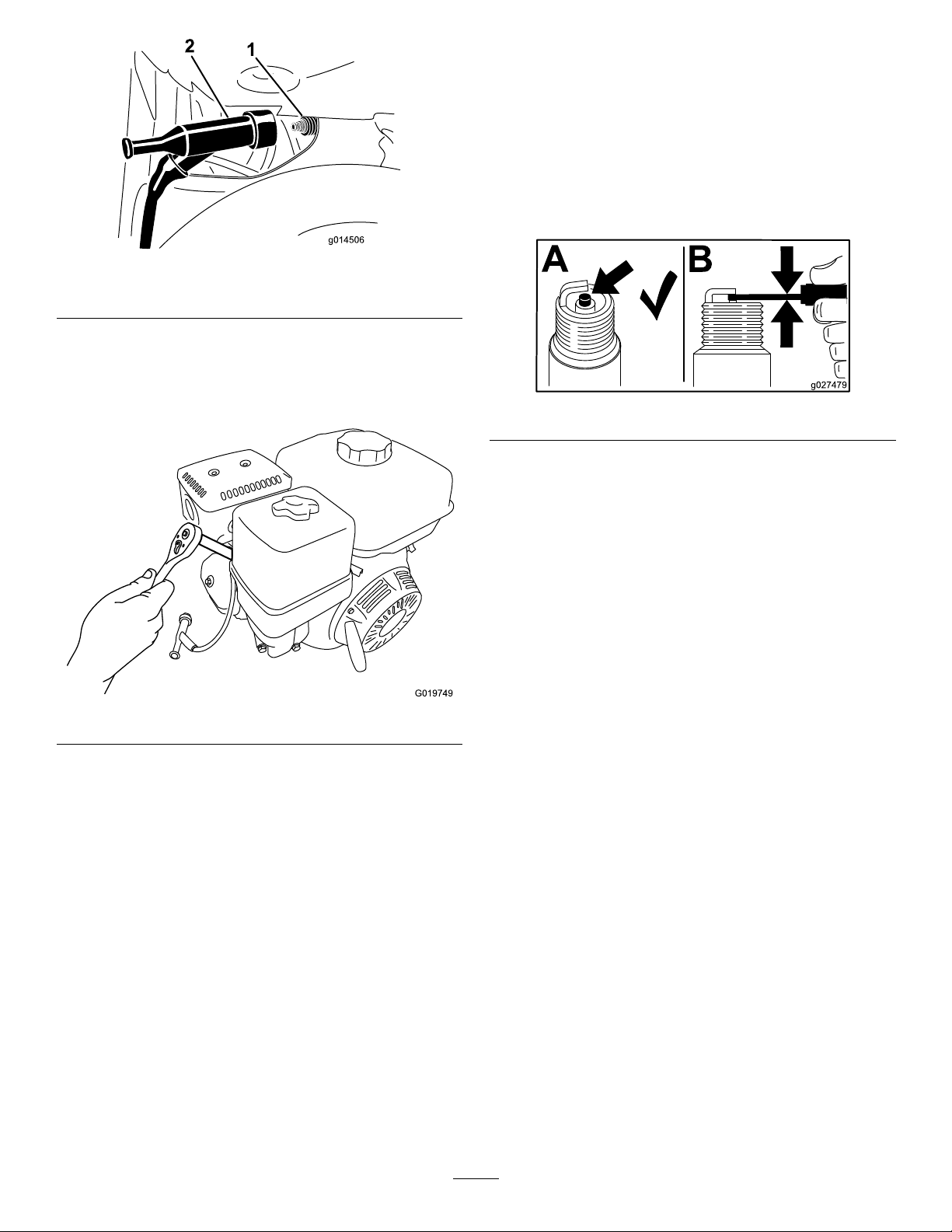
Figure44
G019749
B
A
g027479
CheckingtheSparkPlug
Important:Donotcleanthesparkplug.Alwaysreplace
thesparkplugwhenithas:ablackcoating,worn
electrodes,andoilylm,orcracks.
Note:Ifyouseelightbrownorgrayontheinsulator,the
engineisoperatingproperly.Ablackcoatingontheinsulator
usuallymeansthattheaircleanerisdirty.
Setthegapto0.7to0.8mm(0.028to0.031inch).
1.Sparkplug
4.Cleanaroundthesparkplug.
5.Rotatethesparkplugcounterclockwiseusinga21mm
(13/16inch)spark-plugwrenchtoremovetheplug
andthesealingwasher(Figure45).
2.Wire
Figure45
Figure46
InstallingtheSparkPlug
Important:Ensurethatthegapbetweenthesideand
centerelectrodesiscorrectbeforeinstallingthespark
plug.
1.Threadthesparkplugclockwiseintothespark-plug
holebyhand.
Note:Avoidcross-threadingthesparkplugwiththe
threadsofthespark-plughole.
2.Rotatethesparkplugclockwiseusinga21mm(13/16
inch)spark-plugwrenchuntiltheplugandsealing
washerareseated(Figure45).
3.Tightenthesparkplugasfollows:
•Wheninstallinganin-servicesparkplug,tighten
thepluganadditional1/8to1/4turn.
•Wheninstallinganewsparkplug,tightentheplug
anadditional1/2turn.
4.Pushthespark-plugwireontotheterminalofthespark
plug(Figure44).
32
Page 33
ServicingtheSparkArrester
G019331
10
10
1
2
3
4
5
6
7
8
9
11
12
1
2
G019332
6.Useabrushtocarefullyremovecarbondepositsfrom
thespark-arresterscreen(Figure48).
CleaningtheSparkArrester
ServiceInterval:Every100hours
Note:Asparkarresterisavailableasanoption.Ifyou
requireasparkarrester,contactyourAuthorizedToroService
Dealer.
GenuineT orosparkarrestersareapprovedbytheUSDA
ForestryService.
WARNING
Contactwithhotsurfacesmaycausepersonal
injury.
Keephands,feet,face,clothingandotherbody
partsawaythemuferandotherhotsurfaces.
1.Removethedividerplate;refertoRemovingthe
DividerPlate(page27).
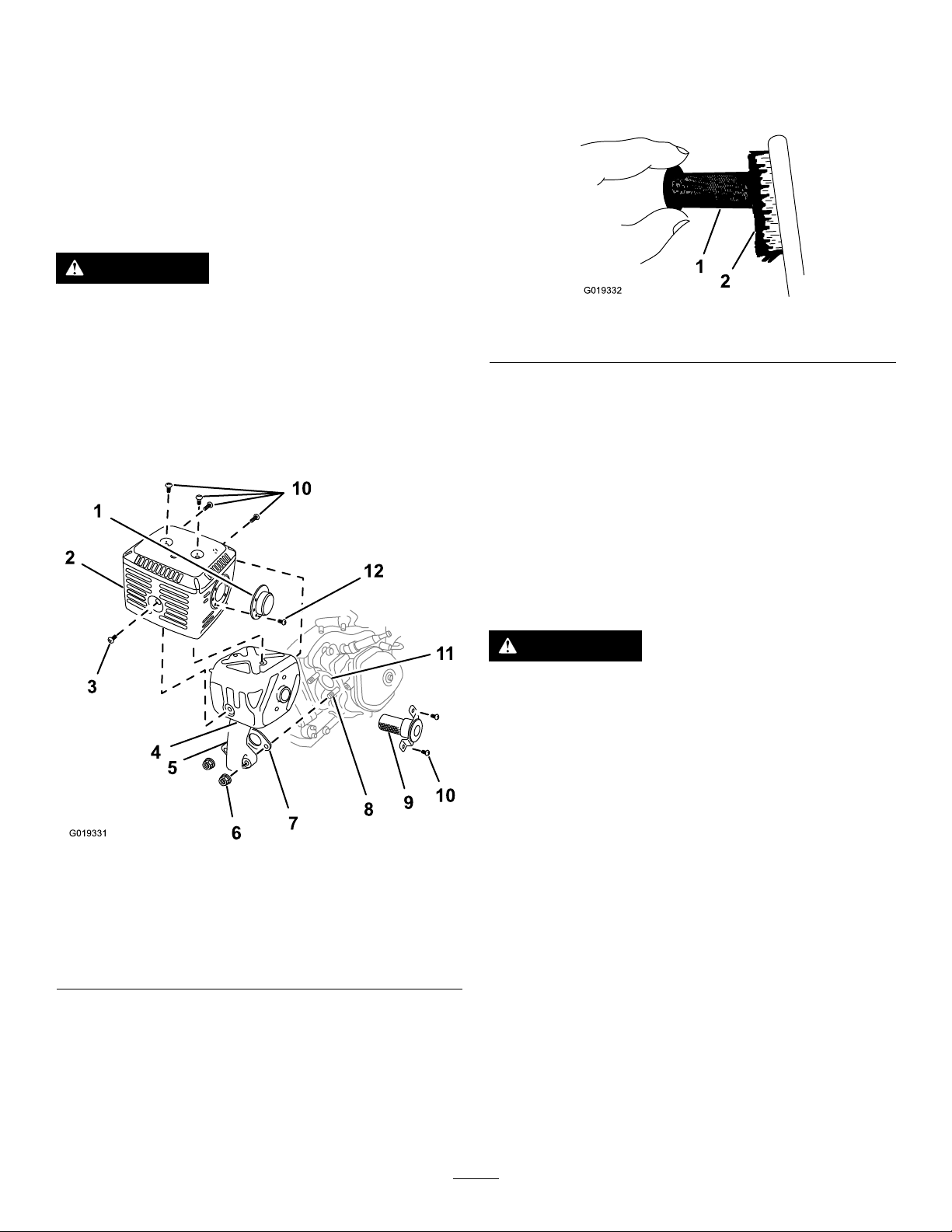
2.Removethe2nuts(8mm)andremovethemufer
fromthecylinder(Figure47).
Note:Replacethesparkarresterifithasbreaksor
holes.
Figure48
1.Screen
7.Installthesparkarrester,muferprotector,exhaust
deector,andmuferinthereverseorderof
disassembly.
8.Installthedividerplate;refertoInstallingtheDivider
Plate(page27).
2.Brush
RemovingandInstallingthe Engine
RemovingtheEngine
WARNING
Thespringisundertensionwheninstalledandcan
causepersonalinjury.
Becarefulwhenremovingthespring.
1.Parkthemachineonalevelsurfaceandshutoffthe
engine.
2.Ensurethattheengineandtheexhaustsystemsurfaces
arecool.
Figure47
1.Deector(if
applicable)
2.Protector
3.Screw(6mm)7.Gasket
4.Mufer8.Bolt(8mm)12.Screw(4mm)
3.Removethe3screws(4mm)fromtheexhaust
deectorandremovethedeector(Figure47).
4.Removethescrews(5mmand6mm)fromthemufer
protector,andremovethemuferprotector(Figure
47).
5.Removethescrew(4mm)fromthesparkarresterand
removethesparkarresterfromthemufer(Figure47).
5.Exhaustpipe
6.Nut(8mm)10.Screws(5mm)
9.Sparkarrester
11.Exhaustport
3.Removethedividerplate;refertoRemovingthe
DividerPlate(page27).
4.Removethebeltguide;refertoRemovingtheBelts
(page37).
5.Removethebelts;refertoRemovingtheBelts(page
37).
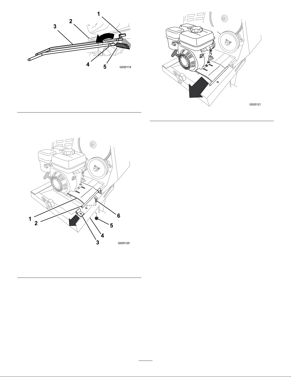
6.Usingaspring-removaltool(ToroPartNo.92-5771),
removethespringfromtheanchorbracketonthe
enginedeck(Figure49).
Note:Leavetheotherendofthespringattachedto
theframeofthemachine.
33
Page 34
3
2
4
1
5
G0201 19
Figure49
G020120
1
2
3
5
6
4
G020121
1.Anchorbracket
2.Enginedeck
3.Spring-removaltool(T oro
PartNo.92-5771)
4.Spring-removaltool
(springremoved)
5.Spring(springremoved)
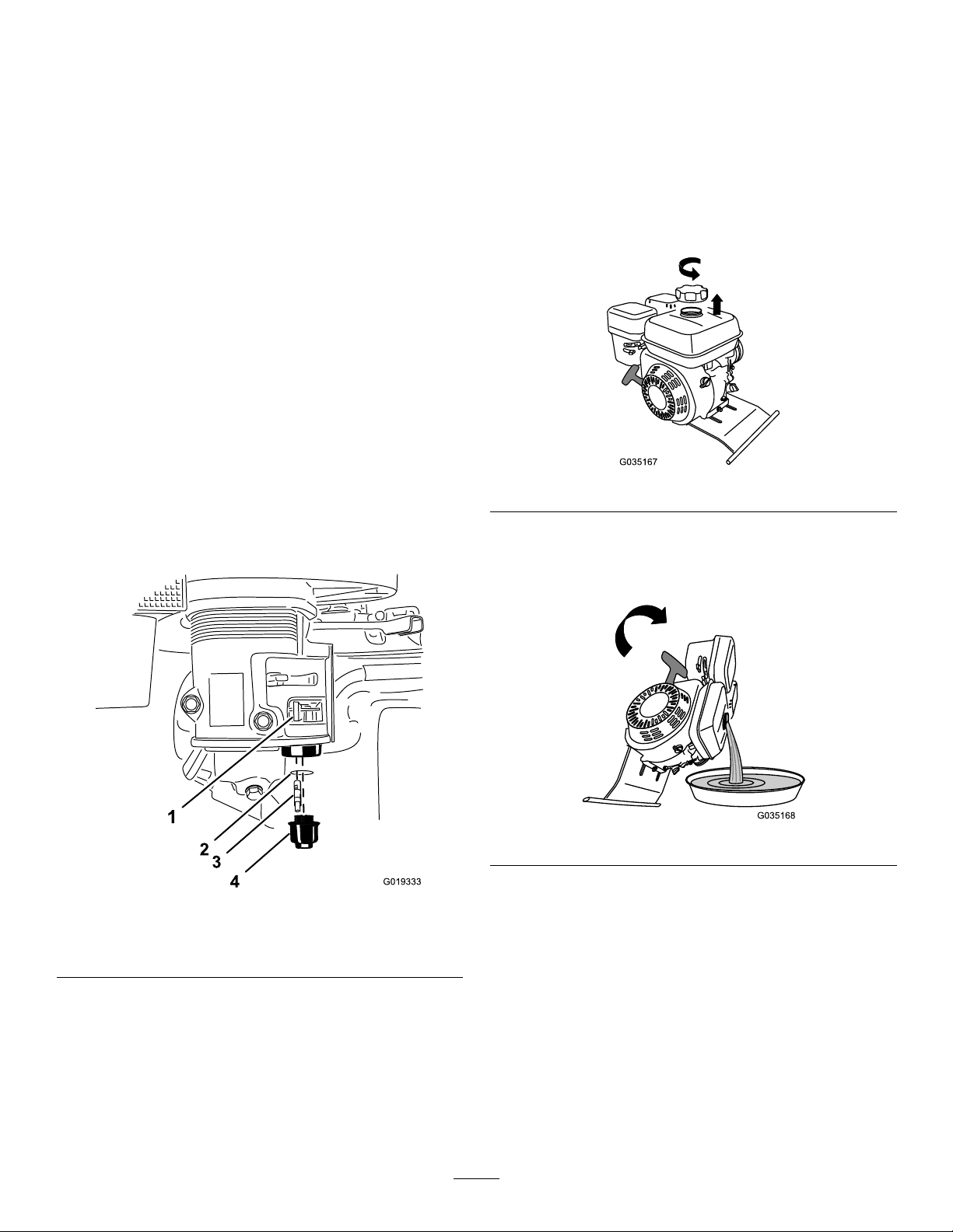
7.Removetheboltandnutthatsecuretherearbracket
fortheenginedeckhingetotheframeofthemachine
(Figure50).
Figure51
10.Removetheengineandenginedeckfromthemachine
(Figure51).
InstallingtheEngine
1.Aligntheengineandenginedecktotherearframeof
themachine.
Note:Thedrivepulleyontheenginemustalign
forward.
2.Alignthepivotontheenginedeckwiththeforward
hingebracket(Figure51).
3.Slidetheenginedeckforwardandthepivotintothe
forwardhingebracket(Figure51).
4.Aligntherearhingebracketwiththepivotonthe
engine-deckhinge(Figure51).
5.Liftupontherearedgeoftheenginedeckandslipthe
hingebracketontothepivot.
6.Securetherearbrackettotheframeofthemachine
Figure50
1.Enginedeck4.Frame
2.Pivot5.Nut
3.Rearhingebracket6.Bolt
usingtheboltandnut(Figure50)removedinstep7of
RemovingtheEngine(page33).
7.Usingaspring-removaltool(ToroPartNo.92-5771),
installthetensionspringtotheanchorbracketonthe
enginedeck(Figure49).
8.Liftuptherearedgeoftheenginedeckandremovethe
hingebracket(Figure50).
9.Slidetheenginedeckrearwardandoutfromthe
forwardhingebracket(Figure51).
Note:Donotremovetheforwardhingebracket.
8.Installthebeltsandbeltguide;refertoInstallingthe
Belts(page37).
9.Adjustthebeltguide;refertoAdjustingtheBeltGuide
(page38).
10.Installthedividerplate;refertoInstallingtheDivider
Plate(page27).
34
Page 35
FuelSystem
2
3
4
1
G019333
Maintenance
10.MovetheleverofthefuelvalvetotheONposition(all
thewaytotheright)andcheckforleaks.Ifitleaks,
replacetheO-ring.
CleaningtheFuel-Sediment Cup
ServiceInterval:Every100hours/Every6months
(whichevercomesrst)—Cleanthe
fuel-sedimentcup.
Yearlyorbeforestorage—Cleanthefuel-sedimentcup.
Underneaththefuelvalveisasedimentcuptocatchdirtin
thefuel.
1.Parkthemachineonalevelsurfaceandshutoffthe
engine.
2.Ensurethattheengineandtheexhaustsystemsurfaces
arecool.
3.MovetheleverofthefuelvalvetotheOFFposition,all
thewaytotheleft(Figure52).
4.Unscrewthesedimentcup(Figure52).
5.RemoveandretainthefuellterandO-ring(Figure
52).
Note:DonotcleantheO-ringinsolvent.
DrainingtheFuelTank
1.Removetheengine;refertoRemovingtheEngine
(page33).
2.Removethefuelcapbyrotatingitcounterclockwise
(Figure53).
Figure53
3.Alignadrainpantothehingeoftheenginedeck.
4.Rotatetheengineonthehingesideoftheenginedeck
anddrainthefuelfromthetank(Figure54).
Figure52
1.Fuelvalve—Offposition3.Fuellter
2.O-ring4.Sedimentcup
6.Cleanthefuellterandsedimentcupusinga
nonammablesolvent,anddryitcarefully .
7.WipetheO-ringwithaclean,drycloth.
8.Installthefuellterinthebottomofthecarburetor
(Figure52).
9.AligntheO-ringintothegrooveinthesedimentcup
andinstallthesedimentcuptothefuel-valvehousing.
Figure54
5.Carefullylowertheengineandenginedeck.
6.Installthefuelcap.
7.Installtheengine;refertoInstallingtheEngine(page
34).
35
Page 36
BeltMaintenance
G019976
1
2
3
4
3
4
3
1
2
3
G020006
G020009
1 2
3
4
5
6 7 8
ServicingtheBelts—Belt-drive Models
InspectingtheBelts
ServiceInterval:Aftertherst25hours—Inspectthebelts
andadjustasnecessary.
Every40hours—Inspectthebeltsandadjustas
necessary.
1.Removethedividerplate;refertoRemovingthe
DividerPlate(page27).
2.MovetheclutchlevertotheOFFposition.
3.Examinethebeltsforwearordamage.Ifthebeltsare
wornordamaged,replacethem;refertoInstallingthe
Belts(page37).
4.Examinethepulleysforwear,damage,and
misalignment;refertoAligningthePulleys(page39).
A.MovetheclutchlevertotheOFFposition.
B.Loosenthenutsandboltsthatsecuretheengine
totheenginedeck(Figure56).
Figure56
1.Idlerpulley3.Nutandbolt
2.Setscrew
4.Enginedeck
5.Installthedividerplate;refertoInstallingtheDivider
Plate(page27).
AdjustingtheBeltTension
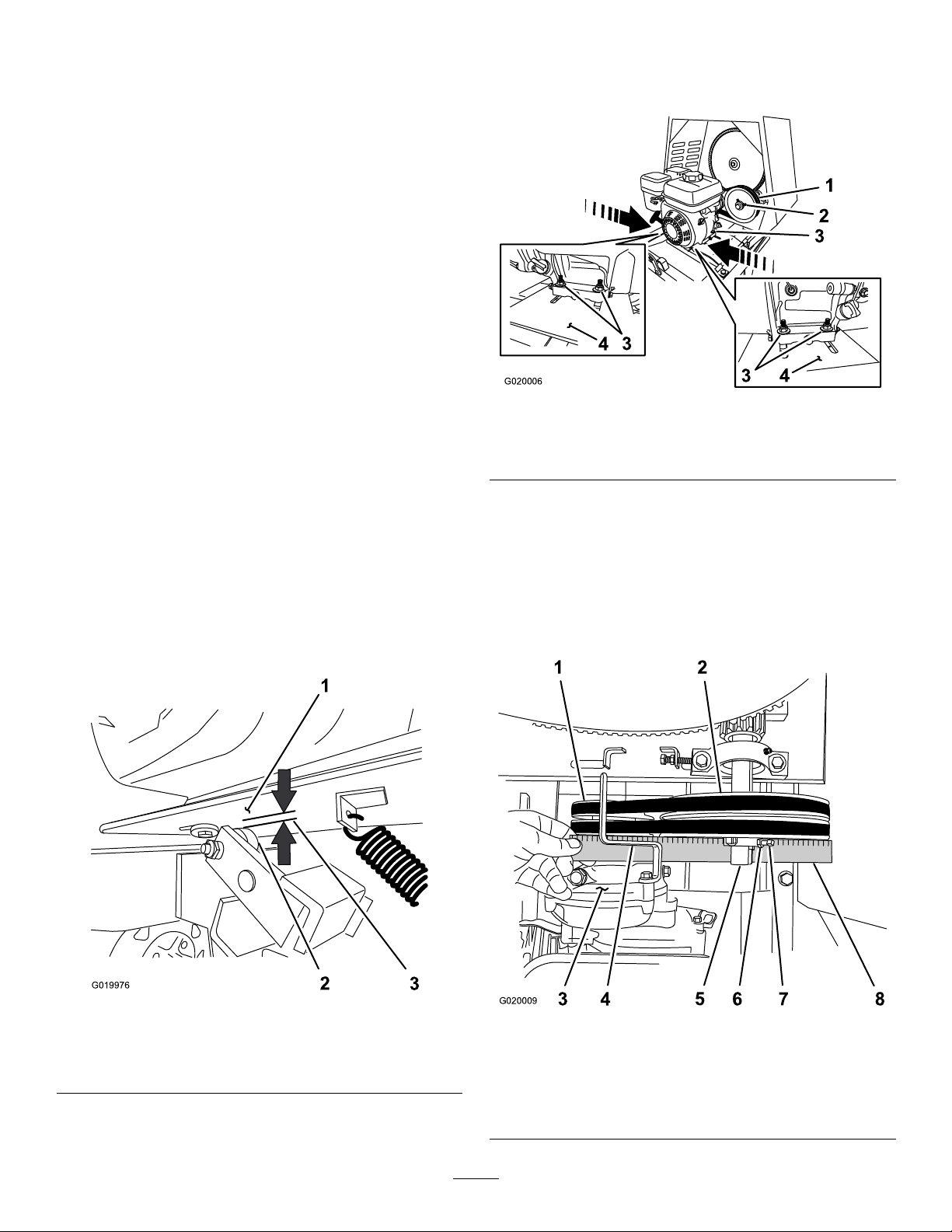
Clutchairgap:2.5to6.5mm(3/32to1/4inch)
1.MovetheclutchlevertotheONposition.
2.Measuretheairgapbetweentheenginedeckandthe
rollerontheclutch(Figure55).
C.Movetheenginepositionasfollows:
•Increasetheairgap—movetheengine
awayfromtheidlerpulley(Figure56).
•Decreasetheairgap—movetheengine
towardtheidlerpulley(Figure56).
D.Alignastraightedgeacrosstheenginepulleyand
theidlerpulley(Figure57).
Figure55
1.Enginedeck
2.Clutchroller
3.Ifthemeasuredairgapisnotwithinthespecied
range,adjustthegapasfollows:
3.Clutchairgap:2.5to6.5
mm(3/32to1/4inch)
Figure57
1.Enginepulley
2.Idlerpulley6.Jamnut
3.Reductioncase(engine)7.Setscrew
4.Beltguide
36
5.Idlershaft
8.Straightedge
Page 37
E.Ifneeded,pivottheengineontheenginedeck
2
G020010
2
3
4
1
G020012
untiltheenginepulleyandtheidlerpulleyare
alignedtothestraightedge(Figure57).
F.Tightenthenutsandboltsthatsecuretheengine
totheenginedecktoatorqueof18N∙m(13ft-lb).
G.Checktheairgapbetweentheenginedeckand
therollerontheclutch.Iftheairgapisnotwithin
thespeciedrange,repeatstep3untiltheairgap
measurementiswithinthespeciedrange.
H.Installthedividerplate;refertoInstallingthe
DividerPlate(page27).
Replacingthe Belts—Belt-driveModels
ServiceInterval:Every2years—Replacethebelts.
Figure59
1.Enginepulley3.Idlerpulley
2.Forwardbelt4.Rearbelt
RemovingtheBelts
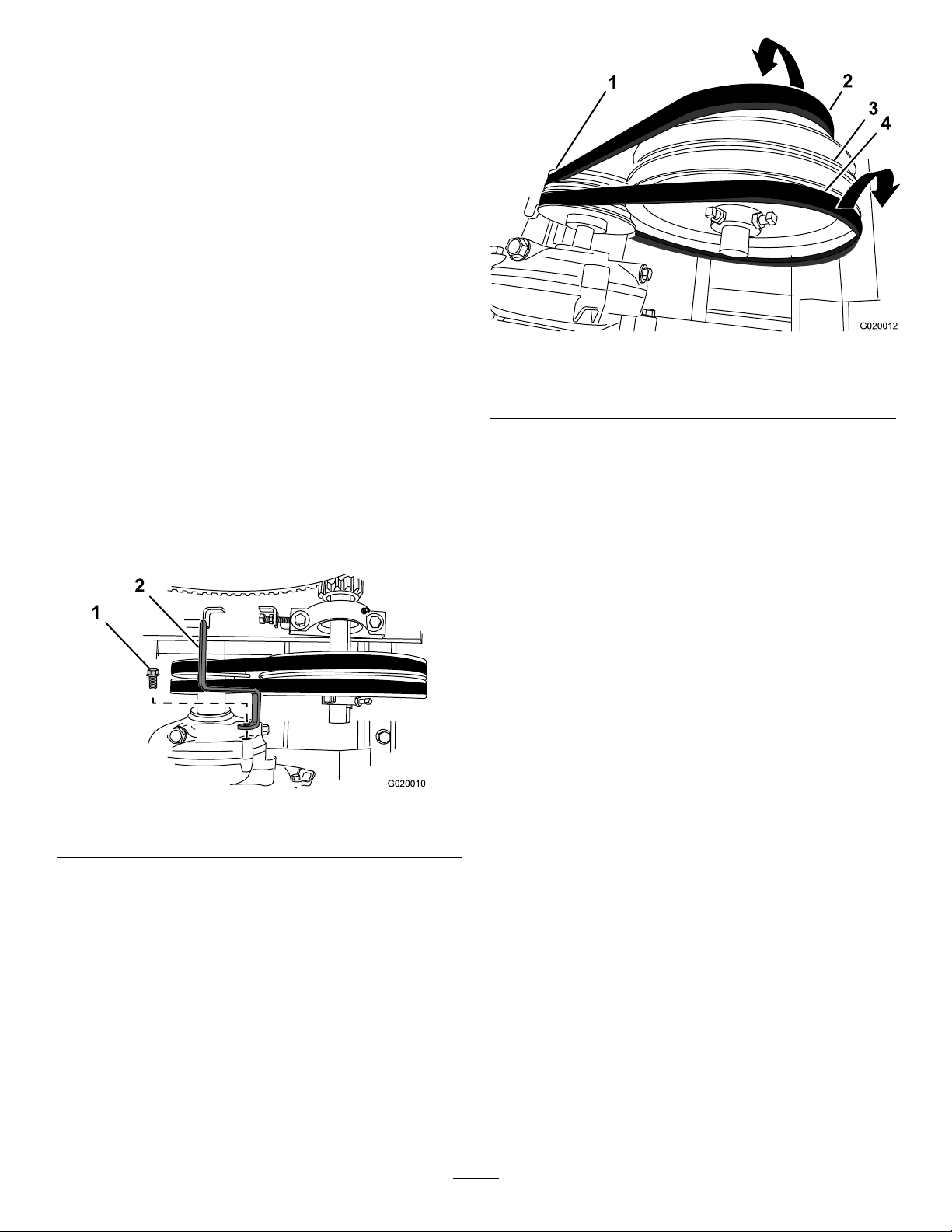
1.MovetheclutchlevertotheOFFposition.
2.Removethedividerplate;refertoRemovingthe
DividerPlate(page27).
3.Removetheboltthatsecuresthebeltguidetothe
engineandremovethebeltguide(Figure58).
Figure58
1.Bolt2.Beltguide
4.Sliptheforwardbeltforwardandofftheidlerpulley
(Figure59).
5.Sliptherearbeltrearwardandofftheidlerpulley
(Figure59).
6.Slipthebeltsofftheenginepulley .
7.Removethebeltsfromthemachine.
InstallingtheBelts
1.EnsurethattheclutchleverisintheOFFposition.
2.Aligntherearbelttothereargrooveintheengine
pulley.
Note:Donotaligntherearbelttotheidlerpulley.
3.Aligntheforwardbelttotheforwardgrooveofthe
idlerpulley.
4.Sliptherearbeltovertheidlerpulleyandalignthebelt
totherearpulleygroove.
5.Sliptheforwardbeltovertheenginepulleyandalign
thebelttotheforwardpulleygroove.
6.Checkthebelttension;refertostep1,step2,andstep
3inAdjustingtheBeltTension(page36).
7.Looselysecurethebeltguidetotheengine(Figure58)
withtheboltthatwasremovedinstep3ofRemoving
theBelts(page37).
8.Adjustthebeltguide;refertoAdjustingtheBeltGuide
37
(page38).
9.Installthedividerplate;refertoInstallingtheDivider
Plate(page27).
Page 38
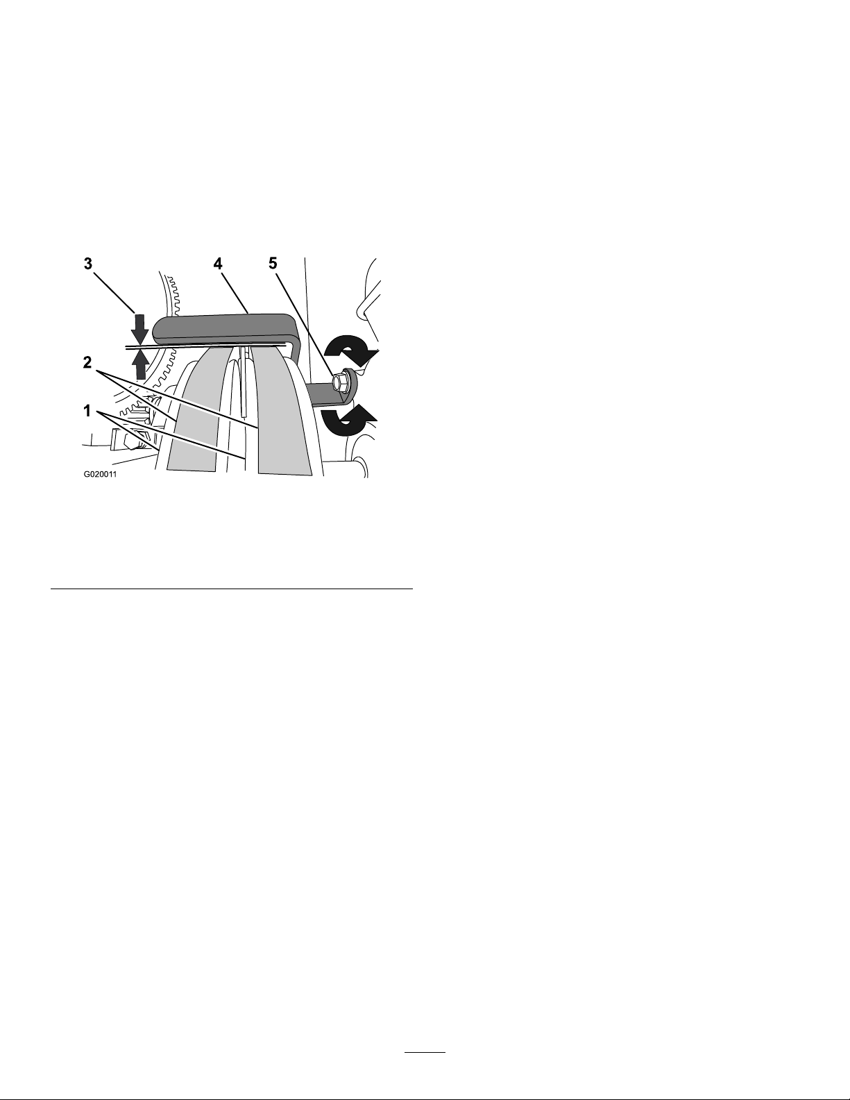
AdjustingtheBeltGuide
G02001 1
3 4
5
1
2
CheckingtheClutchOperation
Note:Toaccessthebeltguide,removethedividerplate;
refertoRemovingtheDividerPlate(page27).
Guideairgap:2.5to4.0mm(3/32to5/32inch)
1.EnsurethattheclutchleverisintheONposition.
2.Ensurethatthebelttensioniscorrect;referto
AdjustingtheBeltTension(page36).
3.Checkthattheairgapbetweenthebeltguideandthe
beltsis2.5to4.0mm(3/32to5/32inch);referto
Figure60.
ServiceInterval:Every40hours—Checktheclutch
operation
Important:Thepaddlesmustnotrotateinanempty
drumwhentheclutchleverisintheOFFposition.
1.MovetheclutchlevertotheOFFposition.
2.Starttheengine.
3.IfthepaddlesrotatewiththeclutchlevertotheOFF
positiondothefollowing:
A.Shutofftheengine.
B.Checktheairgapbetweenthebeltguideandthe
belts.
Note:Iftheairgapislargerthan4.0mm(5/32
inch),decreasethegapbetweenthebeltguide
andthebelts;refertoAdjustingtheBeltGuide
(page38).
4.Repeatsteps1,2,and3untilallthefollowing
conditionsaremet:
•Theengineisrunat2/3throttle.
•TheclutchleverisintheOFFposition.
1.Enginepulleys4.Beltguide
2.Belts5.Bolt
3.Guideairgap:2.5to4.0
mm(3/32to5/32inch)
4.Iftheairgapisnotwithinthespeciedrange,dothe
following:
A.Loosentheboltthatsecuresthebeltguidetothe
engine(Figure60).
Important:Ensurethatthebeltguideis
towardtheenginepulley.
B.Rotatethebeltguideupordownuntilthereis
anairgapof2.5to4.0mm(3/32to5/32inch)
betweentheguideandeachbelt(Figure60).
Important:Thebeltguideshouldnot
contactthebeltswiththeclutchleverinthe
ONposition.
Note:Iftheairgapbetweenthebeltguideand
bothbeltscannotbeattained,thenoneofthe
beltsistoolong.
Figure60
•Thepaddlesdonotrotateinanemptydrum.
C.Tightentheboltthatsecuresthebeltguidetothe
engine(Figure60).
D.Checktheclutchoperation;refertoCheckingthe
ClutchOperation(page38).
5.Installthedividerplate;refertoInstallingtheDivider
Plate(page27).
38
Page 39
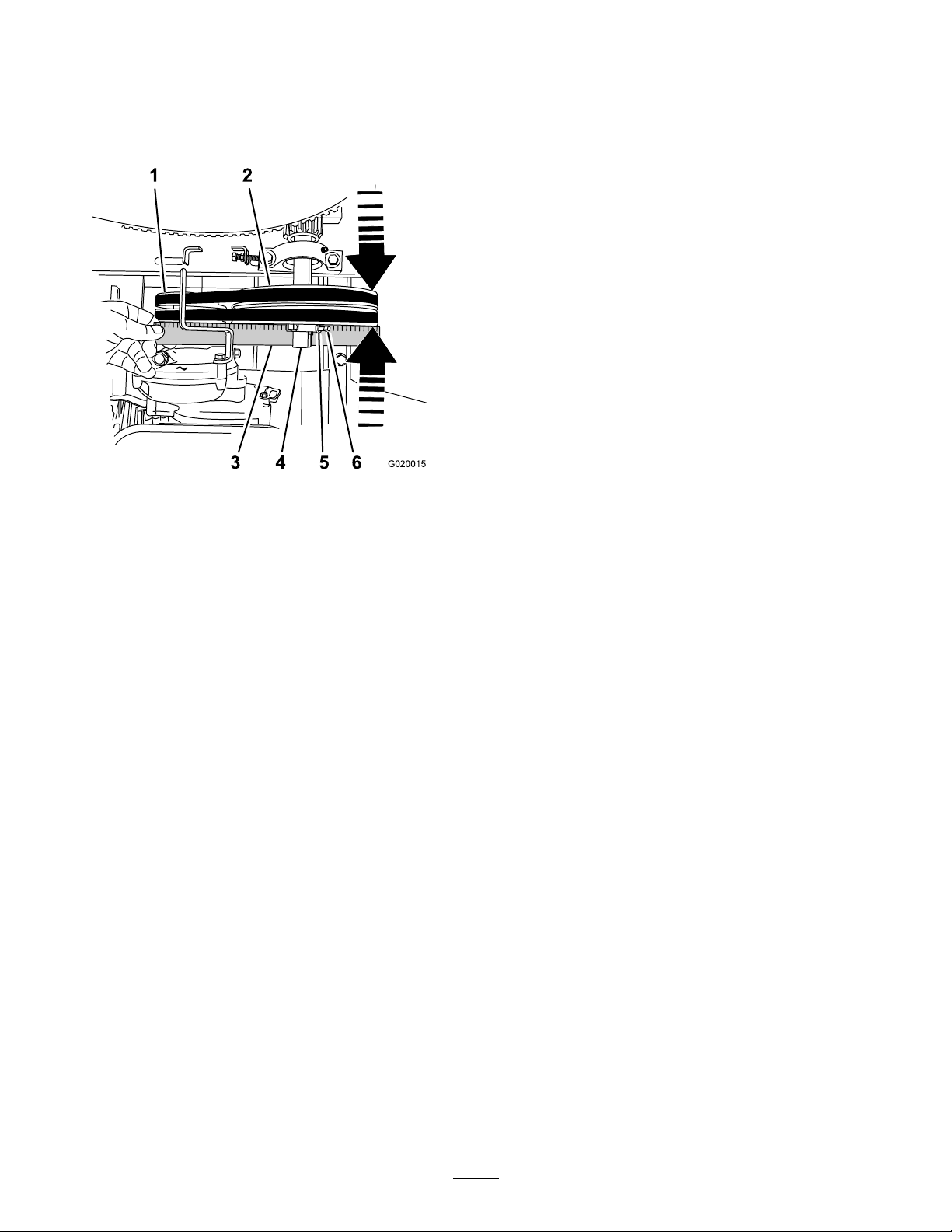
AligningthePulleys
G020015
53 6
1 2
4
1.Removethedividerplate;refertoRemovingthe
DividerPlate(page27).
2.Placeastraightedgeacrossthefaceoftheenginepulley
andtheidlerpulley(Figure61).
Figure61
Cleaning
CleaningtheMachine
Regularcleaningandwashingwithmilddetergentandwater
increasesthelifespanofthemachine.Cleanthemachine
aftereachusebeforethedirthardens.
Removedirtandgrimefromtheexternalpartsoftheentire
machine,especiallytheengine.Cleandirtandconcrete
materialsfromtheoutsideoftheengine.
Ensurethatthefuelcapandtheoil-llcap/dipstickare
securetoavoidgettingwaterintheengine.
Usecarewhenusingahigh-pressuresprayerbecauseitcan
damagesafetydecals,instructionsigns,andtheengine.
Important:Lubricatethetrunnionsaftercleaning;refer
toLubricatingtheBearingsandSeals(page28).
1.Enginepulley
2.Idlerpulley5.Locknut
3.Straightedge6.Setscrew
Note:Bothpulleysmustbealignedushwiththe
straightedge.
3.Ifthepulleysarenotaligneddothefollowing:
A.MovetheclutchlevertotheOFFposition.
B.Loosenthelocknutsandsetscrewsthatsecurethe
idlerpulleytotheidlershaft(Figure61).
C.Usingasoft-facemallet,taptheidlerpulley
forwardorbackwardalongtheidlershaftuntil
theenginepulleyandtheidlerpulleyarealigned
tothestraightedge(Figure61).
D.Tightenthesetscrewsandlocknutsthatsecurethe
idlerpulleytotheidlershaft(Figure61).
4.Installthedividerplate;refertoInstallingtheDivider
Plate(page27).
4.Idlershaft
39
Page 40

Storage
9.Checkandtightenallbolts,nuts,andscrews.Repairor
replaceanypartthatisdamaged.
StoringtheMachine
Forstorageover30days,preparethemachineasfollows:
1.Removedirtandgrimefromtheexternalpartsofthe
entiremachine,especiallytheengine.Cleandirtand
debrisfromtheoutsideoftheenginecylinder-head
nsandblowerhousing.
Important:Y oucanwashthemachinewithmild
detergentandwater.
2.Conditionthefuelsystemasfollows:
A.Addapetroleum-basedstabilizer/conditionerto
fuelinthetank.Followthemixinginstructions
fromthestabilizermanufacturer.Donotusean
alcohol-basedstabilizer(ethanolormethanol).
Important:Donotstore
stabilizer/conditionedfuelover90days.
Note:Fuelstabilizer/conditionerismost
effectivewhenmixedwithfreshfuelandusedat
alltimes.
B.Runtheenginefor5minutestodistributethe
conditionedfuelthroughthefuelsystem.
10.Paintallscratchedorbaremetalsurfaceswithpaint
availablefromyourAuthorizedToroDealer.
11.Storethemachineinaclean,drygarageorstoragearea.
12.Coverthemachinetoprotectitandkeepitclean.
C.Shutofftheengine,allowittocool,anddrainthe
fueltankusingapump-typesiphon.Disposeof
fuelproperly;recycleitaccordingtolocalcodes.
D.Starttheengineandrunituntilitstops.
E.Choketheengine.
F.Startandruntheengineuntilitdoesnotstart
again.
3.Cleanthesedimentcup;refertoCleaningthe
Fuel-SedimentCup(page35).
4.Servicetheaircleaner;refertoServicingtheAir
Cleaner(page29).
5.Changetheenginecrankcaseoil;refertoChangingthe
EngineOil(page31).
6.Removethesparkplugandcheckthecondition;refer
toRemovingtheSparkPlug(page31).
7.Conditiontheengineasfollows:
A.Removethesparkplugandpour2tablespoons
ofengineoilintothespark-plughole;referto
RemovingtheSparkPlug(page31).
B.Pulltherecoil-starthandleslowlytocrankthe
engineanddistributetheoilinsidethecylinder.
C.Installthesparkplug;refertoInstallingtheSpark
Plug(page32).
Note:Donotinstallthewireonthesparkplug.
8.Greasethemachine;refertoLubricatingtheBearings
andSeals(page28).
40
Page 41

Troubleshooting
Problem
Theenginedoesnotstart.
Theenginelackspowerorrunsrough.
PossibleCauseCorrectiveAction
1.Thefuel-valveleverisintheOFF
position.
2.Thechokeisclosed
3.Thechokeisopen.
4.TheengineOn/OffswitchisintheOFF
position.
5.Theengineoillevelislow(engines
withtheoil-levelswitch).
6.Thefueltankisempty.6.Fillthefueltankwithfreshfuel.
7.Theenginecontainsbad/oldfuel.7.Drainthefueltankandcarburetor.
8.Thesparkplugisfouledorimproperly
gapped.
9.Thesparkplugiswetwithfuel(ooded
engine).
10.Thespark-plugwireislooseor
disconnected.
1.Theairlterisrestricted.1.Cleanorreplacetheairlter
2.Theenginecontainsbad/oldfuel.2.Drainthefueltankandcarburetor.
3.Thereiswaterorcontaminationinthe
fuel.
4.Thefuellineisrestricted.4.Cleanthefuellterandsedimentcup.
5.Thechokeisclosed
6.Thesparkplugiswornorhasbuildup
ontheelectrodes.
7.Thereistoomuchoilintheengine
crankcase.
1.Movethefuel-valvelevertotheON
position.
2.Openthechokewhenstartingahot
engine.
3.Closethechokewhenstartingacold
engine.
4.RotatetheswitchtotheONposition.
5.Filltheengine,withtherecommended
oil,totheproperlevel.
Refuelwithfreshgasoline.
8.Gaporreplacethesparkplug.
9.Removethesparkplug,dryit,and
installtheplug.Starttheenginewith
thethrottleintheMAXposition.
10.Removethespark-plugwire,cleanthe
spark-plugterminalandtheterminal
socketinthebootofthespark-plug
wire,andreinstallthespark-plugwire.
element(s).
Refuelwithfreshgasoline.
3.Drainthefueltankandcarburetor.
Refuelwithfreshgasoline.
5.Openthechoke.
6.Checktheelectrodegapandadjustor
replacethesparkplug.
7.Draintheoiltotheproperlevel.
Thebeltssliporcomeoffthepulleys.
isintheOFFposition.
leverisintheONposition.
Thepaddlesrotateslowlywhentheclutch
leverisintheONposition.
1.Thebelttensionisinsufcient.
2.Thebeltsareworn.2.Replacethebelts.
3.Thepulley(s)areworn.3.ContactyourAuthorizedService
4.Thepulley(s)aremisaligned.4.Alignthepulley(s).
1.Theclutchleverisnotadjusted
correctly.
2.Thebeltguideisnotadjustedcorrectly.2.Adjustthebeltguide.
1.Theclutchleverisnotadjusted
correctly.
2.Thepaddlesarestuckinthedrum
1.Theclutchleverisnotadjusted
correctly.
1.Adjustthebelttension.
Dealer.
1.Adjustthebelttension. Thepaddlesrotatewhentheclutchlever
1.Adjustthebelttension. Thepaddlesdonotrotatewhentheclutch
2.Cleanthepaddlesanddrum.
1.Adjustthebelttension.
41
Page 42

Notes:
42
Page 43

Notes:
43
Page 44

Alimitedwarranty(seewarrantyperiodsbelow)
TheToroWarranty
Concrete,
Masonry,and
Compaction
Equipment
ConditionsandProductsCovered
TheT oroCompanyanditsafliate,T oroWarrantyCompany,pursuantto
anagreementbetweenthem,jointlywarrantyourT oroConcrete,Masonry ,
andCompactionEquipmentProductslistedbelowtobefreefromdefectsin
materialsorworkmanship.
Thiswarrantycoversthecostofpartsandlabor,butyoumustpay
transportationcosts.
Thefollowingtimeperiodsapplyfromthedateofpurchase:
ProductsWarrantyPeriod
ConcreteMixers
•SpindleBearingsLifetime*(originalowneronly)
MortarMixers1year
•DrumBearingsandSealsLifetime*(originalowneronly)
ForwardPlateCompactors
ReversiblePlates1year
RammerCompactors
MudBuggy1year
VibratingTrenchRoller2years
ConcreteSaws
MasonrySaws
PowerTrowels1year
Screeds
ConcreteVibrators
Whereawarrantableconditionexists,wewillrepairtheProductatnocost
toyouincludingdiagnosis,labor,andparts.
*
LifetimeWarranty-Ifthebearing(s)orseal(s)onyourmixerfail,itwillbereplacedunderwarranty ,
atnocostforpartsorlabor.
1year
2years
2years
1year
1year
1year
1year
InstructionsforObtainingWarrantyService
IfyouthinkthatyourToroProductcontainsadefectinmaterialsor
workmanship,followthisprocedure
1.ContactanyAuthorizedServicingOutlettoarrangeserviceattheir
dealership.T olocateoneconvenienttoyou,accessourwebsiteat
www.T oro.com.Select“WheretoBuy”andselect“Contractor”under
producttype.Y oumayalsocallourtollfreenumberbelow.
2.Bringtheproductandyourproofofpurchase(salesreceipt)tothem.
3.IfforanyreasonyouaredissatisedwiththeServiceOutlet’sanalysis
orwiththeassistanceprovided,contactusat:
SWSCustomerCareDepartment
ToroWarrantyCompany
811 1LyndaleAvenueSouth
Bloomington,MN55420-1196
TollFree:800-888-9926
**
ToroAuthorizedRentalCustomerswhohavepurchasedproductsdirectlyfromT oroandhave
signedtheT oroRentalCustomerAgreementhavetheabilitytoperformtheirownwarrantywork.
PleasevisitT oro’sRentalPortalforelectronicwarrantyclamlingproceduresorcallthetollfree
numberabove.
**
:
OwnerResponsibilities
YoumustmaintainyourToroProductbyfollowingthemaintenance
proceduresdescribedintheOperator’sManual.Suchroutinemaintenance,
whetherperformedbyadealerorbyyou,isatyourexpense.Parts
scheduledforreplacementasrequiredmaintenance(“MaintenanceParts”),
arewarrantedfortheperiodoftimeuptothescheduledreplacementtime
forthatpart.Failuretoperformrequiredmaintenanceandadjustmentscan
begroundsfordisallowingawarrantyclaim.
ItemsandConditionsNotCovered
Notallproductfailuresormalfunctionsthatoccurduringthewarrantyperiod
aredefectsinmaterialsorworkmanship.Thisexpresswarrantydoesnot
coverthefollowing:
•Productfailureswhichresultfromtheuseofnon-T ororeplacement
parts,orfrominstallationanduseofadd-on,modied,orunapproved
accessories
•Productfailureswhichresultfromfailuretoperformrequired
maintenanceand/oradjustments
•ProductfailureswhichresultfromoperatingtheProductinanabusive,
negligentorrecklessmanner
•Partssubjecttoconsumptionthroughuseunlessfoundtobedefective.
Examplesofpartswhichareconsumed,orusedup,duringnormal
productoperationinclude,butarenotlimitedto,belts,wipers,spark
plugs,tires,lters,gaskets,wearplates,seals,O-rings,drivechains,
clutches.
•Failurescausedbyoutsideinuence.Itemsconsideredtobeoutside
inuenceinclude,butarenotlimitedto,weather,storagepractices,
contamination,useofunapprovedcoolants,lubricants,additives,or
chemicals,etc.
•Normal“wearandtear”items.Normal“wearandtear”includes,butis
notlimitedto,wornpaintedsurfaces,scratcheddecals,etc.
•Repairsnecessaryduetofailuretofollowrecommendedfuel
procedure(consultOperator'sManualformoredetails)
–Removingcontaminantsfromthefuelsystemisnotcovered
–Useofoldfuel(morethanonemonthold)orfuelwhichcontains
morethan10%ethanolormorethat15%MTBE
–Failuretodrainthefuelsystempriortoanyperiodofnon-use
overonemonth
•Anycomponentcoveredbyaseparatemanufacturer’swarranty
•Pickupanddeliverycharges
GeneralConditions
RepairbyanAuthorizedServicingOutletorSelf-ServiceasanAuthorized
RentalCustomerisyoursoleremedyunderthewarranty.
NeitherTheToroCompanynorToroWarrantyCompanyisliablefor
indirect,incidentalorconsequentialdamagesinconnectionwiththe
useoftheToroProductscoveredbythiswarranty,includingany
costorexpenseofprovidingsubstituteequipmentorserviceduring
reasonableperiodsofmalfunctionornon-usependingcompletionof
repairsunderthiswarranty .Allimpliedwarrantiesofmerchantability
andtnessforusearelimitedtothedurationofthisexpresswarranty.
Somestatesdonotallowexclusionsofincidentalorconsequential
damages,orlimitationsonhowlonganimpliedwarrantylasts,sothe
aboveexclusionsandlimitationsmaynotapplytoyou.
Thiswarrantygivesyouspeciclegalrights,andyoumayalsohaveother
rightswhichvaryfromstatetostate.
ExceptfortheenginewarrantycoverageandtheEmissionswarranty
referencedbelow,ifapplicable,thereisnootherexpresswarranty .The
EmissionsControlSystemonyourProductmaybecoveredbyaseparate
warrantymeetingrequirementsestablishedbytheU.S.Environmental
ProtectionAgency(EPA)ortheCaliforniaAirResourcesBoard(CARB).
RefertotheCaliforniaEmissionControlWarrantyStatementsuppliedwith
yourProductorcontainedintheenginemanufacturer’sdocumentationfor
details.
CountriesOtherthantheUnitedStatesorCanada
CustomerswhohavepurchasedT oroproductsoutsidetheUnitedStatesorCanadashouldcontacttheirT oroDistributor(Dealer)toobtainguarantee
policiesforyourcountry,province,orstate.IfforanyreasonyouaredissatisedwithyourDistributor'sserviceorhavedifcultyobtainingguarantee
information,contacttheT oroimporter.Ifallotherremediesfail,youmaycontactusatT oroWarrantyCompany.
AustralianConsumerLaw:AustraliancustomerswillnddetailsrelatingtotheAustralianConsumerLaweitherinsidetheboxoratyourlocalT oro
Dealer.
374-0288RevC
 Loading...