

Page 1
FormNo.3378-857RevA
G020896
MM-SeriesMortarMixer
ModelNo.68013C—SerialNo.313000001andUp
ModelNo.68014C—SerialNo.313000001andUp
ModelNo.68016C—SerialNo.313000001andUp
ModelNo.68017C—SerialNo.313000001andUp
ModelNo.68020C—SerialNo.313000001andUp
ModelNo.68021C—SerialNo.313000001andUp
ModelNo.68024C—SerialNo.313000001andUp
Registeratwww.T oro.com.
OriginalInstructions(EN)
*3378-857*A
Page 2

WARNING
CALIFORNIA
Proposition65Warning
Thisproductcontainsachemicalorchemicals
knowntotheStateofCaliforniatocausecancer,
birthdefects,orreproductiveharm.
Theengineexhaustfromthisproduct
containschemicalsknowntotheStateof
Californiatocausecancer,birthdefects,
orotherreproductiveharm.
Useofthisproductmaycauseexposureto
chemicalsknowntotheStateofCalifornia
tocausecancer,birthdefects,orother
reproductiveharm.
ThissparkignitionsystemcomplieswithCanadianICES-002.
Becauseinsomeareastherearelocal,state,orfederal
regulationsrequiringthatasparkarresterbeusedonthe
engineofthismachine,asparkarresterisavailableas
anoption.Ifyourequireasparkarrester,contactyour
AuthorizedToroServiceDealer.
GenuineTorosparkarrestersareapprovedbytheUSDA
ForestryService.
Important:ItisaviolationofCaliforniaPublic
ResourceCodeSection4442touseoroperatetheengine
onanyforest-covered,brush-covered,orgrass-covered
landwithoutasparkarrestermufermaintainedin
workingorder,ortheengineconstricted,equipped,and
maintainedforthepreventionofre.Otherstatesor
federalareasmayhavesimilarlaws.
1-800-424-9153);gotohttp://www .safercar.gov;orwrite
to:Administrator,NHTSA,1200NewJerseyAvenue,
SEWestBuilding,Washington,DC20590.Youcanalso
obtainotherinformationaboutmotorvehiclesafetyfrom
http://www.safercar.gov.
•TocontactTransportCanada,youmaycall
1-800-333-0510or(819)994-3328;goto
http://www.tc.gc.ca/roadsafety/;writeto:Road
SafetyandMotorVehicleRegulationDirectorate,
TransportCanada,TowerC,PlacedeVille,330
SparksStreet,Ottawa,Ontario,K1A0N5;oremail
[email protected].
Introduction
Thismachineisdesignedtomixmortar,plaster,reproong
material,grout,andothersmall-grainedPortlandcement
products.Avehicleequippedwithanappropriatepintlehitch
orballhitchcantowthemachine.
Readthisinformationcarefullytolearnhowtooperateand
maintainyourproductproperlyandtoavoidinjuryand
productdamage.Youareresponsibleforoperatingthe
productproperlyandsafely .
YoumaycontactTorodirectlyatwww .Toro.comforproduct
andaccessoryinformation,helpndingadealer,ortoregister
yourproduct.
Wheneveryouneedservice,genuineToroparts,oradditional
information,contactanAuthorizedServiceDealerorToro
CustomerServiceandhavethemodelandserialnumbersof
yourproductready.Writethenumbersinthespaceprovided.
Theenclosed
informationregardingtheUSEnvironmentalProtection
Agency(EPA)andtheCaliforniaEmissionControl
Regulationofemissionsystems,maintenance,and
warranty.Replacementsmaybeorderedthroughthe
enginemanufacturer.
Ifyoubelievethatyourmachinehasadefectwhichcould
causeacrashorcouldcauseinjuryordeath,youshould
immediatelyinformtheNationalHighwayTrafcSafety
Administration(NHTSA)ifyouliveintheUnitedStates,
orTransportCanadaifyouliveinCanada,inadditionto
notifyingTheToroCompany.
IfNHTSAorTransportCanadareceivessimilarcomplaints,
itmayopenaninvestigation,andifitndsthatasafetydefect
existsinagroupofmachines,itmayorderarecallandremedy
campaign.However,NHTSAorTransportCanadacannot
becomeinvolvedinindividualproblemsbetweenyou,your
dealer,orTheToroCompany.
Engine Owner's Man ual
issuppliedfor
•TocontactNHTSA,youmaycalltheVehicle
SafetyHotlinetoll-freeat1-888-327-4236(TTY:
©2013—TheToro®Company
8111LyndaleAvenueSouth
Bloomington,MN55420
Contactusatwww.T oro.com.
2
PrintedintheUSA
AllRightsReserved
Page 3
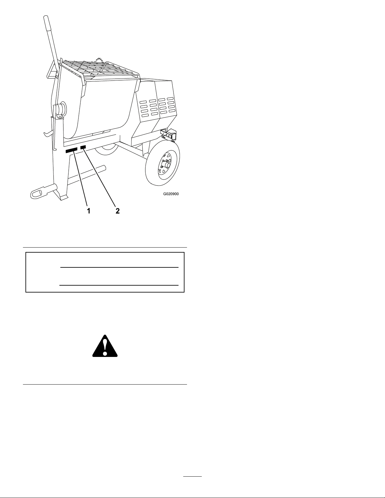
1
G020900
2
Figure1
1.Modelandserialnumber
location
ModelNo.
SerialNo.
2.Vehicleidentication
number(VIN)location
Thismanualidentiespotentialhazardsandhassafety
messagesidentiedbythesafetyalertsymbol(Figure2),
whichsignalsahazardthatmaycauseseriousinjuryordeath
ifyoudonotfollowtherecommendedprecautions.
Figure2
1.Safetyalertsymbol
Thismanualuses2wordstohighlightinformation.
Importantcallsattentiontospecialmechanicalinformation
andNoteemphasizesgeneralinformationworthyofspecial
attention.
TireInformation
TheDOTtireinformationislocatedonthesideofeachtire.
Thisinformationgivesloadandspeedratings.Replacement
tiresshouldhavethesameorbetterratings.
Note:Thevariousmachinesinthismanualhavedifferent
weights;referto
Specications(page13)toensurethatthe
tiresonyourmachinemeetorexceedtheweightrequirements
ofyourmachine.
Contents
Introduction..................................................................2
Safety...........................................................................4
SafeOperatingPractices...........................................4
SafetyandInstructionalDecals.................................7
Setup............................................................................8
1InstallingtheDumpHandle...................................8
2InstallingtheTowPole..........................................8
3InstallingtheSafetyChain......................................9
ProductOverview.........................................................10
Controls...............................................................11
Specications........................................................13
Operation....................................................................13
PreparingtoT owtheMachine..................................13
ExtendingtheAxle—Belt-driveModels....................17
TowingtheMachine...............................................18
PreparingtoUsetheMachine...................................18
OpeningandClosingtheCowl.................................18
AddingFuel...........................................................19
CheckingtheEngineOilLevel.................................20
StartingandStoppingtheEngine..............................21
ControllingthePaddles...........................................22
MixingtheMaterial.................................................23
UsingtheDrum.....................................................24
AdjustingthePaddleBlades.....................................24
Maintenance.................................................................27
RecommendedMaintenanceSchedule(s)......................27
PremaintenanceProcedures........................................28
PreparingtheMachineforMaintenance.....................28
DisconnectingtheSpark-plugWire...........................28
RemovingandInstallingtheDividerPlate..................28
Lubrication...............................................................29
LubricatingtheBearingsandSeals............................29
EngineMaintenance..................................................30
ServicingtheAirCleaner.........................................30
ChangingtheEngineOil.........................................30
ServicingtheSparkPlug..........................................32
ServicingtheSparkArrester.....................................33
RemovingandInstallingtheEngine..........................34
FuelSystemMaintenance...........................................35
ServicingtheFuelSystem........................................35
DriveSystemMaintenance.........................................36
ServicingtheReductionCase—Belt-drive
Models..............................................................36
ServicingtheGearCase—Gear-CaseModel...............38
BeltMaintenance......................................................39
ServicingtheBelts—Belt-driveModels......................39
ReplacingtheBelts—Belt-driveModels.....................40
AligningthePulleys—Belt-driveModels....................42
ReplacingtheLightBulbs............................................43
ReplacingtheRear-facingBulbs................................43
3
Page 4

ReplacingtheSide-facingBulbs................................43
Cleaning...................................................................44
CleaningtheMachine..............................................44
Storage........................................................................44
StoringtheMachine................................................44
Troubleshooting...........................................................46
Safety
Improperlyusingormaintainingthemachinecanresult
ininjury.Toreducethepotentialforinjury,complywith
thesesafetyinstructionsandalwayspayattentiontothe
safetyalertsymbol,whichmeans:
or
Danger
complywiththeinstructionmayresultinpersonalinjury
ordeath.
—personalsafetyinstruction.Failureto
SafeOperatingPractices
Thismachineiscapableofamputatinghands.Alwaysfollow
allsafetyinstructionstoavoidseriousinjuryordeath.
WARNING
Machiningorhandlingstone,masonry,concrete,
metal,andothermaterialscangeneratedust,mists,
andfumescontainingchemicals,suchassilica,
knowntocauseseriousorfatalinjuryorillness,
suchasrespiratorydisease,silicosis,cancer,birth
defects,orotherreproductiveharm.
Caution
,
W ar ning
,
•Controldust,mist,andfumesatthesource
wherepossible.Usewaterfordustsuppression,
whenfeasible.
•Usegoodworkpracticesandfollowthe
recommendationsofthemanufacturer
orsupplier,CCOHS,OSHA,andother
occupationalandtradeassociations.
•Alwaysfollowrespiratoryprecautions.
•Whenthehazardsfrominhalationcannotbe
eliminated,theoperatorandanybystanders
shouldweararespiratorapprovedbyCCOHSor
OSHAforthematerialbeinghandled.
WARNING
Engineexhaustcontainscarbonmonoxide,an
odorless,deadlypoisonthatcankillyou.
Donotruntheengineindoorsorinanenclosed
area.
Training
•ReadtheOperator'sManualandothertrainingmaterial.If
theoperator(s)ormechanic(s)cannotreadorunderstand
theinformation,itistheowner'sresponsibilitytoexplain
thismaterialtothem.
•Becomefamiliarwiththesafeoperationoftheequipment,
operatorcontrols,andsafetysigns.
•Alloperatorsandmechanicsshouldbetrained.The
ownerisresponsiblefortrainingtheusers.
4
Page 5

•Neverletchildrenoruntrainedpeopleoperateorservice
theequipment.Localregulationsmayrestricttheageof
theoperator.
•Theowner/usercanpreventandisresponsiblefor
accidentsorinjuriesoccurringtopeopleordamageto
property.
Towing
Checkwithyourlocalcountyorstatetowingsafety
regulations,inadditiontomeetingTransportCanada(or
DepartmentofTransportationifintheU.S.)towingsafety
regulations,beforetowingthemachine.
•Inordertoreducethepossibilityofanaccidentwhile
transportingthemachineonpublicroads,makesure
thetowingvehicleismechanicallysoundandingood
operatingcondition.
•Shutdowntheenginebeforetransportingthemachine.
•Whentowingwithaballhitch,ensurethattheballhitch
youareusingisthepropersizeforthehitchcoupleron
themachine.
•Whentowingwithapintlehitch,ensurethattheeyeof
thetowpoleisthecorrectdimensionforthepintlehook.
•Inspectthehitchandcouplingforwear.Nevertowthe
machinewithdamagedordefectivehitches,couplings,
chains,orothercomponents.
•Checkthetireairpressureonthetowingvehicleandthe
machine.
•Checkthetiretreadandsidewallfordamageandwear.
•Properlyattachthesafetychainstothetowingvehicle.
•Ensurethatthedirectionalandbrakelightsareworking
properly.
•Ensurethatthedirectional,backup,andbrakelightsof
thetowvehicleareworkingproperly .
•Beforetowingchecktomakecertainyourmachineis
correctlyandsecurelyattachedtothetowingvehicle.
•Ensurethatthesafetychainsareproperlysecuredtothe
vehicle,andleaveenoughslackforturning.
•Donotcarryanymaterialinthemachinewhentowing.
•Avoidsuddenstopsandstarts.Thiscancauseskidding,
orjackkning.Smooth,gradualstartsandstopswill
improvetowing.
•Avoidsharpturnstopreventrolling.Towonlywitha
vehiclethathasahitchdesignedfortowing.Donot
attachtowedequipmentexceptatthehitchpoint.
•Donottowthemachinefasterthan88km/h(55mph).
•Usecautionwhenbackingup;useaspotteroutsidethe
vehicletoguideyou.
•Donotallowanyonetositorrideonthemachine.
•Disconnectthemachinefromthetowvehiclebefore
usingit.
•Placechockblocksunderneaththetirestopreventthem
fromrollingwhilethemachineisparked.
Preparation
Becomefamiliarwiththesafeoperationoftheequipment,
operatorcontrols,andsafetysigns.
•Useonlyaccessoriesandattachmentsapprovedbythe
manufacturer.
•Wearpersonalprotectiveequipmentandappropriate
clothingincluding:
–Hardhat
–Respiratorordustmask
–Faceshield
–Safetyglasses
–Hearingprotection
–Safetyshoes
–Longpants
–Shirtwithlongsleevesbuttonedatthewrists
–Tight-ttinggloveswithoutdrawstringsorloosecuffs
•Securelonghair,looseclothing,orjewelrythatmayget
tangledinmovingparts.
•Operatingtheequipmentsafelyrequiresthefullattention
oftheoperator.Donotwearradioormusicheadphones
whileoperatingthemachine.
•Useextracarewhenhandlingfuels.Theyareammable
andthevaporsareexplosive.Usethefollowingpractices
whenhandlingfuel:
–Useonlyanapprovedfuelcontainer.
–Neverremovethefuelcaporaddfuelwiththeengine
running.
–Allowtheenginetocoolbeforerefueling.
–Donotsmoke.
–Neverrefuelordrainthemachineindoors.
–Replacethefuelcapandtightenitsecurely .
–Keepthecontainernozzleincontactwiththetank
duringlling.
–Neverllacontainerwhileitisinsideavehicle,trunk,
pick-upbed,oranysurfaceotherthantheground.
–Neverstorethemachineorfuelcontainerinside
wherethereisanopename,suchasnearawater
heaterorfurnace.
–Iffuelisspilled,wipeitofftheengineandequipment.
•Ensurethatthemachineisonalevelsurfacebefore
operatingthemachine.
•Chockthetiresofthemachinetopreventunintended
movement.
•Beforeeveryuse:
–Inspectthecoupler,ball,andhitch.
–Ensurethatalllightsarefunctioningproperly(if
equippedwithalightkit).
5
Page 6

–Ensurethatthetiresareproperlyinatedas
recommended.
–Ensurethatthelugnutsaretightandtorqued
properly.
–Ensurethatthemachineisproperlysecured.
MaintenanceandStorage
•Beforeperformingmaintenance,dothefollowing:
–Parkthemachineonlevelground.
–Stoptheengine.W aitforallmovementtostopbefore
adjusting,cleaning,orrepairing.
Operation
•Neverrunanengineinanenclosedorpoorlyventilated
area.
•Onlyoperatethemachineingoodlightingconditions.
•Beforestartingthemachine,makesurethatthereareno
personsorobstaclesnearorunderthemachine.
•Shutofftheenginebeforeleavingthemachineforany
reason.
Neverleavearunningmachineunattended.Alwaysstop
theengineandverifythatallmovingpartshavestopped.
•Chockthetiresofthemachineorkeepitattachedtothe
towingvehiclewhenitisnotinuse,topreventitfrom
rolling.
•Avoidprolongedbreathingofexhaustfumes.Engine
exhaustfumescancausesicknessordeath.
•Keephandsawayfromanymovingparts.Keepfeetaway
fromthetiresandthefrontpost.
•Donotoperatethemachineundertheinuenceof
alcoholordrugs.
•Ensurethattheareaisclearofotherpeopleorpetsbefore
operatingthemachine.Stopthemachineifanyoneenters
thearea.
•Neverplaceyourhandsoranysolidobjectintothedrum
whenthemachineisinoperation.
•Donottouchpartswhichmaybehotfromoperation.
Allowthemtocoolbeforeattemptingtomaintain,adjust,
orservicethemachine.
•Nevermovethemachinewhiletheengineisrunning.
•Keepthecowlclosedandlatchedduringoperation.
•Ensurethatalltheguardsandshieldsaresecurelyinplace
beforeoperatingthemachine.
•Disconnectthespark-plugwireandkeepitawayfromthe
sparkplugtopreventaccidentalstartingwhileadjusting
themachine.
•Ifthemixingpaddlesstrikeaforeignobjectorifthe
machineshouldstartmakinganunusualnoiseor
vibration,stoptheengineandemptythedrum.Waitfor
allmovingpartstocometoacompletestopandcool.
Vibrationisgenerallyawarningoftrouble.Disconnect
thespark-plugwireandinspectforcloggingordamage.
Cleanandrepairand/orreplacedamagedparts.
•Donotchangetheenginegovernorsettingoroverspeed
theengine.
•Lightningcancausesevereinjuryordeath.Ifyousee
lightningorhearthunderinthearea,donotoperatethe
machine;seekshelter.
–Lettheenginecoolbeforeperformingmaintenance
orstoring.
–Removethespark-plugwirebeforemakingany
repairs.
–Disengageallpowerandoperationcontrols.
•Neverlubricate,service,repair,oradjustthemachine
whileitisrunning.
•Keepequipmentmaterialsclearfromthemuferand
enginetohelppreventres.Cleanupanyoilorfuel
spillage.
•Neverallowuntrainedpersonneltoservicethemachine.
•Keephands,feet,andclothingawayfrommovingparts.
Ifpossible,donotmakeadjustmentswiththeengine
running.
•Keepallpartsingoodworkingconditionandallhardware
tightened.Replaceallwornordamageddecals.
•Removeanybuildupofgrease,oil,ordebrisfromthe
machine.
•Stopandinspectthemachineifaforeignobjectentersthe
drumorcausesanotherobstruction.Makeanynecessary
repairsbeforestartingthemachine.
•Donottamperwithsafetydevices.
•Chockthetireswhenstoringthemachine.
•Keepallnuts,bolts,screws,andhoseclampssecurely
tightened.Keepequipmentingoodcondition.
•UseonlygenuineTororeplacementpartstoensurethat
theoriginalstandardsaremaintained.
6
Page 7
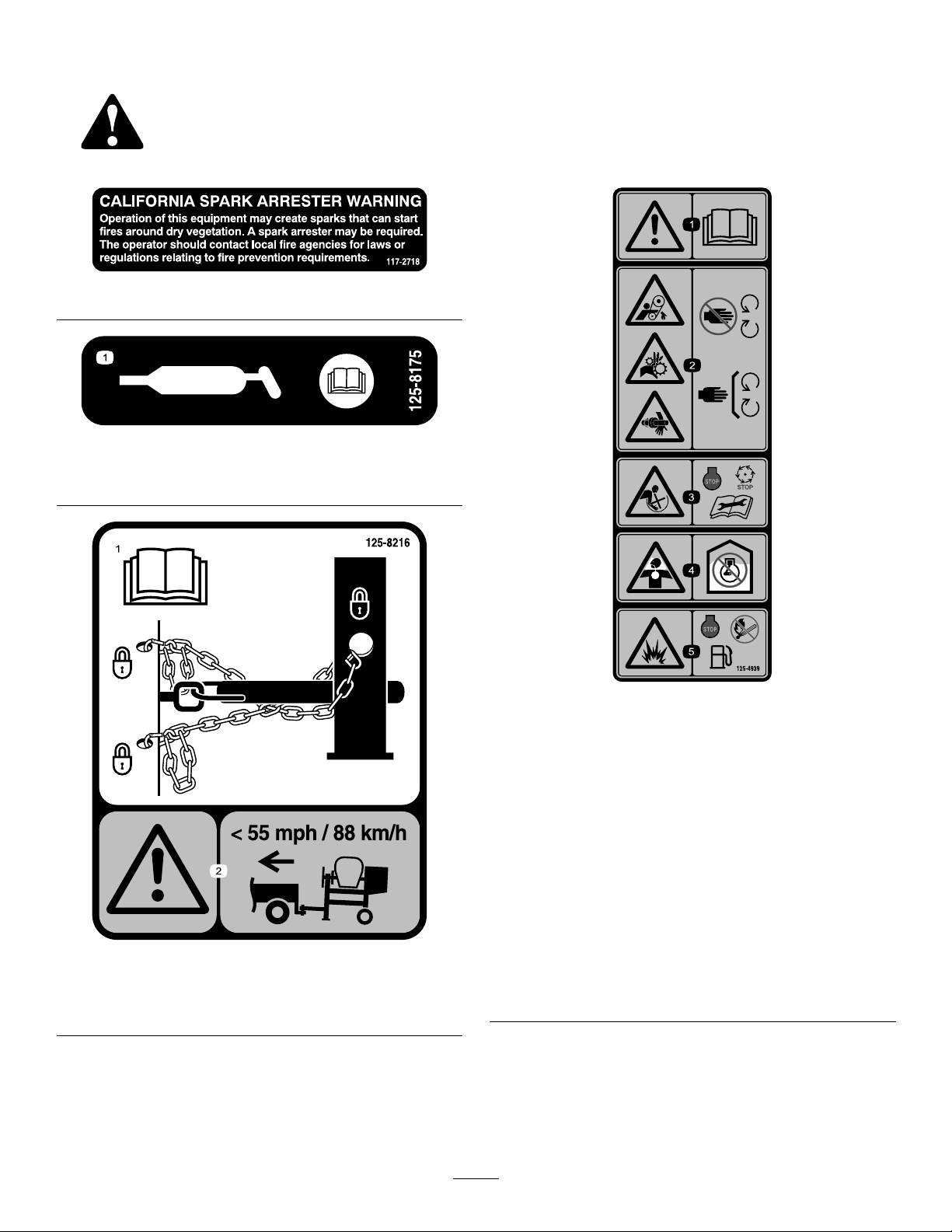
SafetyandInstructionalDecals
Safetydecalsandinstructionsareeasilyvisibletotheoperatorandarelocatednearanyareaofpotential
danger.Replaceanydecalthatisdamagedorlost.
117–2718
125–8175
1.ReadtheOperator’sManualforinformationongreasing
themachine.
1.ReadtheOperator’s
Manualforinformationon
howtotowthemachine.
125–8216
2.Warning—limittowing
speedtolessthan55mph
/88km/h.
1.Warning—readthe
Operator’sManual.
2.Handandarm
entanglementatthe
beltdrive;crushinghazard
ofhand;entanglement
hazardofhandatthe
shaft—keephandsaway
frommovingparts;keep
allguardsandshieldsin
place.
3.Entanglementhazardat
paddles—stoptheengine
andwaitforallmoving
partstostopbefore
performingmaintenance.
125–4939
4.Toxicgasinhalation
hazard—Don’trunthe
engineinanenclosed
space.
5.Explosionhazard—stop
theengineandkeep
awayfromameswhen
refueling.
7
Page 8
Setup
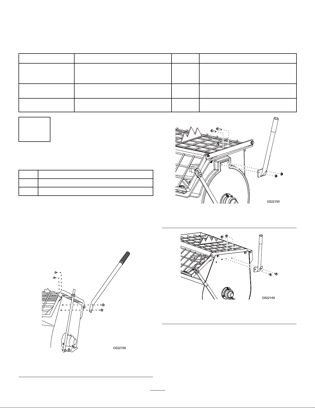
G022169
G022150
G022149
LooseParts
Usethechartbelowtoverifythatallpartshavebeenshipped.
ProcedureDescription
Dumphandle1
1
2
3
Bolt2
Nut2
Towpolekit(soldseparately)
Safetychain
Connectinglink
1
InstallingtheDumpHandle
Partsneededforthisprocedure:
1Dumphandle
2Bolt
2Nut
InstallingtheDumpHandletotheDrum
1.Cutthecabletiestoremovethedumphandlefrom
theundersideofthegrate.
2.Positionthedumphandlesothattheboltholesalign
withtheboltholesinthedrum(Figure3,Figure4,
orFigure5).
Qty.
Installthedumphandle.
1Installthetowpole.
1
2
Installthesafetychain.
Models68014C,68017C,68021C
Use
Figure4
Figure3
Models68013C,68016C,68020C
Figure5
Model68024C
3.Insertthe2boltsthroughtheboltholesinthedump
handleandthedrum(Figure3,Figure4,orFigure5).
4.Installanutontoeachbolt,andtightenthembyhand
topreventcross-threading.
5.Tightenthenutswithawrenchwhileusinganother
wrenchtokeeptheboltsfromspinning.
8
Page 9
2
5
1
2
4
6
3
G019804
A
B
D
g019883
2
3
4
3
1
3
InstallingtheTowPole
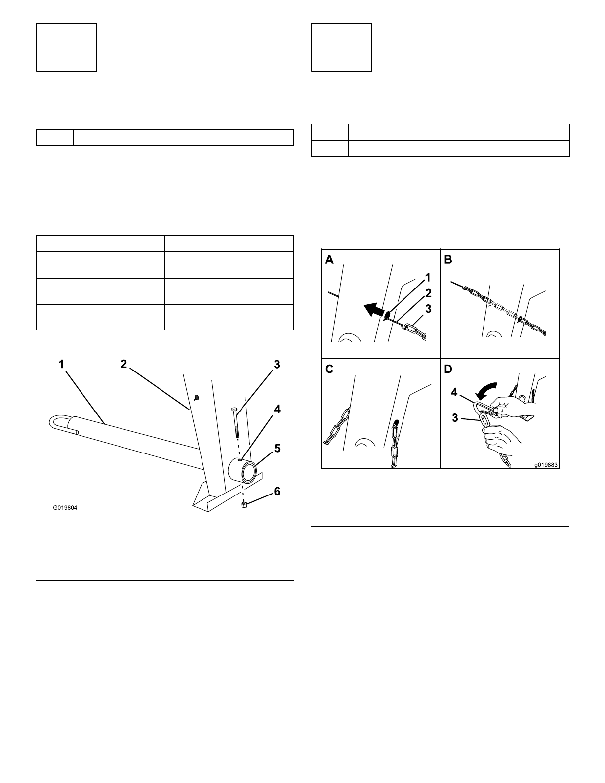
Partsneededforthisprocedure:
1
Towpolekit(soldseparately)
InstallingtheTowPoletotheMachine
Note:Thetowpoleispurchasedseparatelyandincludesthe
nutandboltneededforinstallation.
Themachinehasthefollowingtowpoleoptions:
HitchT ypeLength
50mm(2inch)ball—stamped78.7cm(31inches)or127cm
50mm(2inch)ball—forged78.7cm(31inches)or127cm
Pintle
1.Removetheboltandnutfromthetowpole(Figure6).
(50inches)
(50inches)
78.7cm(31inches)or127cm
(50inches)
InstallingtheSafetyChain
Partsneededforthisprocedure:
1
Safetychain
2
Connectinglink
InstallingtheSafetyChaintothe
Machine
1.Formahookontheendofabendablepieceofrod
orstiffwire(notincluded),andinsertitthroughboth
keyholesinthefrontpostofthemachine(Figure7).
Figure6
1.Towpole4.Bolthole
2.Frontpost
3.Bolt6.Nut
2.Slidethetowpoleforwardandaligntheholeinthe
polewiththeholeintheframetting(Figure6).
3.Inserttheboltthroughtheholesinthettingandthe
pole(
4.Threadthenutontotheboltandtightenthemuntil
theyaretightagainsttheframetting(Figure6).
Note:Iftheself-lockingnyloninsertinthelocknut
wearswithuse,replacethenutwithanewGrade5or
Grade8locknut.
Figure6).
5.Frametting
Figure7
1.Keyhole
2.Rodorwire(notincluded)4.Connectinglink
2.Attachthesafetychaintothelengthofrodorwire
(Figure7).
3.Pulltherod,orwire,andthesafetychainthroughboth
keyholes(Figure7).
Note:Ensurethatapproximatelyequallengthsof
safetychainextendfromeithersideofthefrontpost.
3.Safetychain
InstallingtheConnectingLinks
1.Aligntheconnectinglinktothelastlinkinoneendof
thesafetychain(
2.Inserttheconnectinglinkthroughthechainlinkuntil
theconnectinglinksnapsclosed(Figure7).
3.Repeatsteps1and2toinstalltheotherconnectinglink
intheotherendofthesafetychain.
9
Figure7).
Page 10
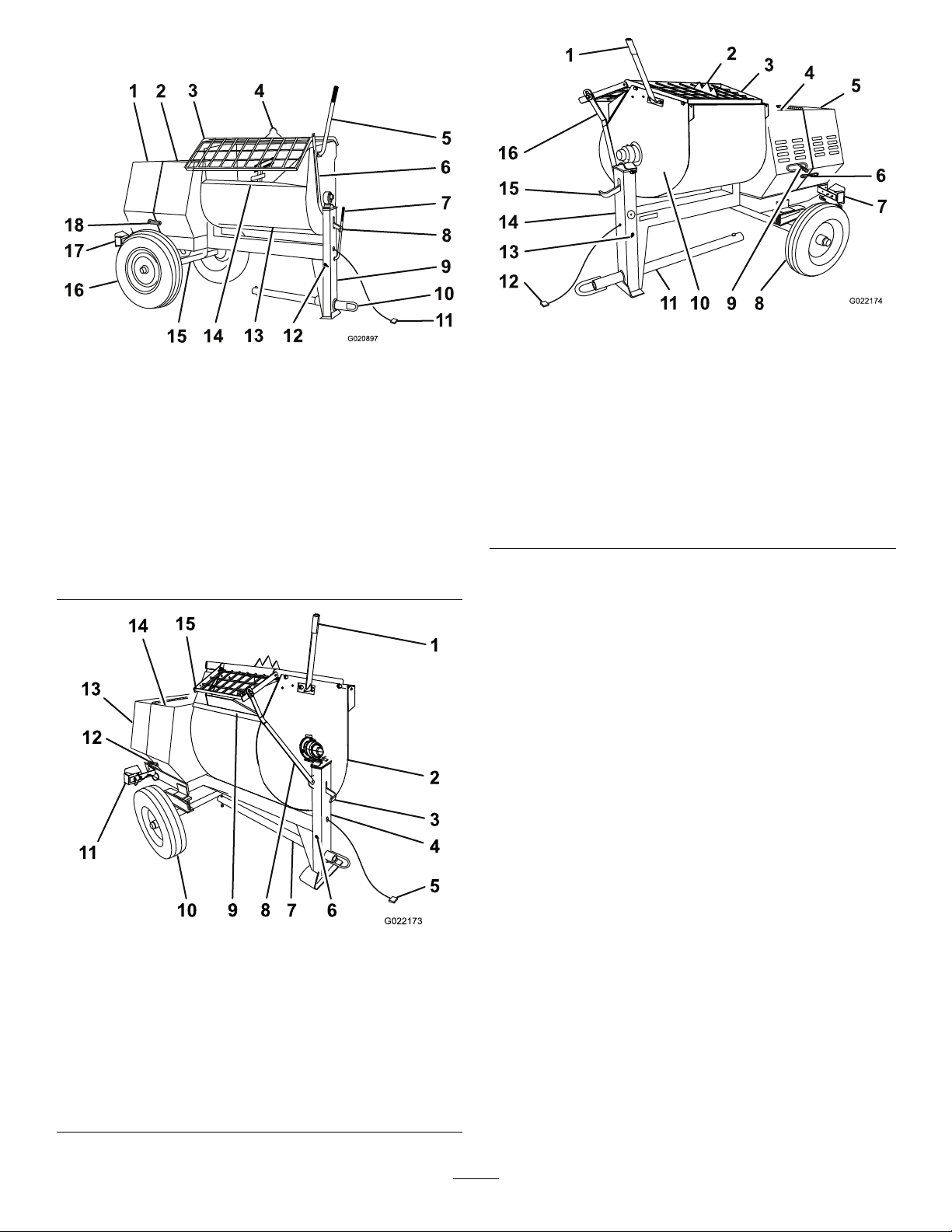
ProductOverview
G020897
1
2
3
4
5
6
8
9
10
12
13
14
15
16
7
11
17
18
G022173
1
2
3
4
67
8
9
10
11
12
13
5
14
15
15
16
G022174
13
1
2
3
4
5
6
7
8
9
10
11
12
14
Figure8
Rightside(models68013C,68014C,68016C,68017C,
68020C,and68021C)
1.Rearcowl
2.Frontcowl8.Drumlatch
3.Grate
4.Bagsplitter10.T owpole16.Wheel
5.Dumphandle11.Lightingwire
6.Grateliftarm12.Safety-chain
7.Clutchlever
9.Frontpost15.Axle
harness
keyhole
13.Drum
14.Chute
assembly
17.Light(2)
18.Cowllatch
Figure10
Leftside(model68024C)
1.Dumphandle
2.Bagsplitter8.Wheel
3.Grate9.Clutchlever
4.Frontcowl10.Drum
5.Rearcowl11.T owpole
6.Cowllatch
7.Light(2)13.Safety-chain
assembly
12.Lightingwire
harness
keyhole
14.Frontpost
15.Drumlatch
16.Grateliftarm
Rightside(model68024C)
1.Dumphandle
2.Drum7.Towpole
3.Drumlatch
4.Frontpost
5.Lightingwire
harness
6.Safety-chain
8.Grateliftarm
9.Chute
10.Wheel
Figure9
keyhole
assembly
11.Light(2)
10
12.Cowllatch
13.Rearcowl
14.Frontcowl
15.Grate
Page 11
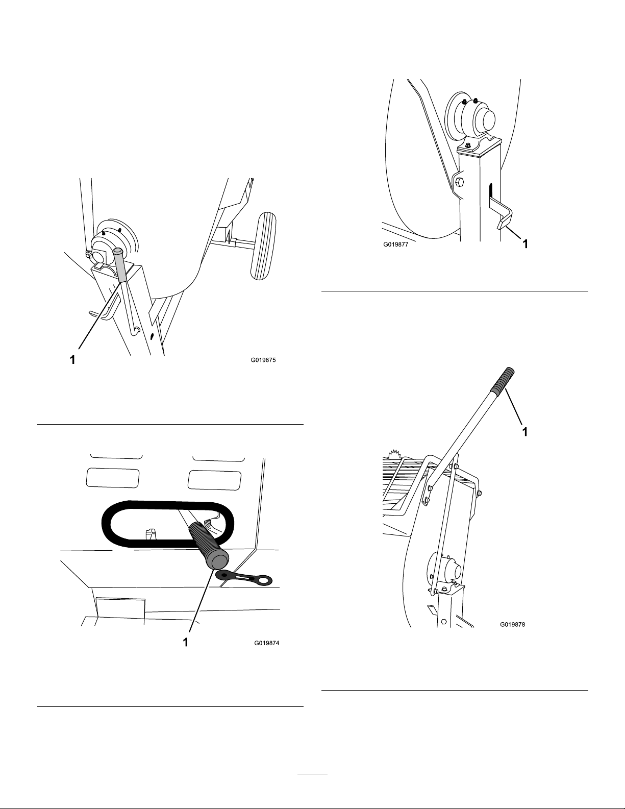
Controls
G019875
1
1
G019874
1
G019877
G019878
1
Becomefamiliarwithallthecontrolsbeforeyoustartthe
engineandoperatethemachine.
ClutchLever
Theclutchleverengagesanddisengagesenginepowertothe
paddles.
•Belt-drivemodels(models68013C,68014C,68016C,
68017C,68020C,and68021C)
DrumLatch
Thedrumlatchsecuresthedrumtothemixposition(upright)
formixingoperationsandwhentransportingthemachine.
Figure13
1.Drumlatch
DumpHandle
1.Clutchlever
•Gear-casemodel(model68024C)
Belt-drivemodels
Gear-casemodel
Figure11
Figure12
Usethedumphandletorotatethedrumtothedumpposition
andtorotatethedrumtothemixposition(upright).
Figure14
Models68013C,68016C,and68020Cshown
1.Dumphandle
1.Clutchlever
11
Page 12
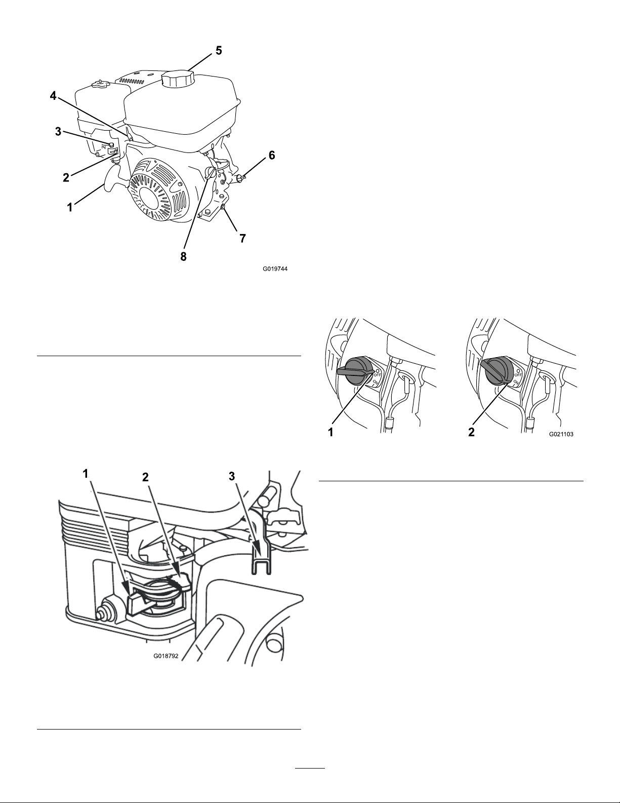
EngineControls
1
2
3
4
5
6
7
8
G019744
1
2
3
G018792
OFF
ON
1
OFF
ON
G021 103
2
Figure15
1.Recoil-starthandle5.Fuelcap
2.Fuelvalve
3.Chokelever7.Oil-drainplug
4.Throttlelever
6.Oilcap/dipstick
8.On/Offswitch
ChokeLever
Usethechokelever(Figure16)tostartacoldengine.Before
pullingtherecoil-starthandle,movethechokelevertothe
closedposition.Oncetheengineisrunning,movethechoke
levertotheopenposition.Donotusethechokeiftheengine
isalreadywarmeduportheairtemperatureishigh.
ThrottleLever
Thethrottlelever(Figure16)controlsthespeed(rpm)ofthe
engine.Itislocatednexttothechokelever.Itsetstheengine
speedandthereforecanincreaseanddecreasetherotation
speedofthemixingpaddles.Forbestperformance,setthis
controltothefastpositionwhenmixingmaterial.
EngineOn/OffSwitch
TheOn/Offswitch(Figure17)allowstheoperatorofthe
machinetostartandstoptheengine.Thisswitchislocated
onthefrontoftheengine.RotatetheOn/Offswitchtothe
Onpositiontostartandruntheengine.RotatetheOn/Off
switchtotheOffpositiontostoptheengine.
FuelValve
Thefuelvalve(Figure16)islocatedunderneaththechoke
lever.MovetheleverforthefuelvalvetotheOnposition
beforeattemptingtostarttheengine.Whenyouhavenished
mixing,stoptheengineandmovethefuelvalvelevertothe
Figure17
Offposition.
1.Offposition2.Onposition
Recoil-startHandle
Tostarttheengine,pulltherecoil-starthandle(Figure15)
quicklytoturntheengineover.Theenginecontrolsdescribed
abovemustallbesetcorrectlyfortheenginetostart.
Oil-levelSwitch
Theoil-levelswitchislocatedinsidetheengine,anditwill
notallowtheenginetorunintheeventtheoillevelisbelow
thesafeoperatinglimit.
Figure16
1.Fuelvalve3.Throttlelever
2.Chokelever
12
Page 13

Specications
G019741
Note:Specicationsanddesignaresubjecttochangewithoutnotice.
MachineSpecications
Model
Batch
Capacity
TotalV olume0.20cubicm
DrumMaterial
Length
(withouttow
pole)
Width86cm
Height137cm
Weight250kg
Axle86to117
EngineHonda
Drivebeltbeltbeltbeltbeltbeltgearbox
68013C68014C68016C68017C68020C68021C68024C
0.17cubicm
(6.0cubicft)
(6.9cubicft)
Steel
163cm
(64inches)
(34inches)
(54inches)
(550lb)
cm(34to
46inches)
extendable
®
GX160
0.17cubicm
(6.0cubicft)
0.20cubicm
(6.9cubicft)
Polyethylene
163cm
(64inches)
86cm
(34inches)
137cm
(54inches)
241kg
(530lb)
86to1 17
cm(34to
46inches)
extendable
®
Honda
GX160
0.17cubicm
(6.0cubicft)
0.20cubicm
(6.9cubicft)
Steel
163cm
(64inches)
86cm
(34inches)
137cm
(54inches)
250kg
(550lb)
86to1 17
cm(34to
46inches)
extendable
®
Honda
GX240
0.17cubicm
(6.0cubicft)
0.20cubicm
(6.9cubicft)
Polyethylene
163cm
(64inches)
86cm
(34inches)
137cm
(54inches)
241kg
(530lb)
86to1 17
cm(34to
46inches)
extendable
®
Honda
GX240
0.23cubicm
(8.0cubicft)
0.25cubicm
(9.0cubicft)
Steel
193cm
(86inches)
86cm
(34inches)
137cm
(54inches)
275kg
(605lb)
86to1 17
cm(34to
46inches)
extendable
®
Honda
GX240
0.23cubicm
(8.0cubicft)
0.25cubicm
(9.0cubicft)
Polyethylene
193cm
(86inches)
86cm
(34inches)
137cm
0(54inches)
266kg
(585lb)
86to1 17
cm(34to
46inches)
extendable
®
Honda
GX240
0.34cubicm
(12.0cubicft)
0.42cubicm
(14.8cubicft)
Steel
205.7cm
(81inches)
142.2cm
(50inches)
150cm
(59inches)
508kg
(1120lb)
142cm
(56inches)
xed
®
Honda
GX340
Operation
PreparingtoTowtheMachine
Important:Ensurethatyourtowvehiclehastowing
capacityfortheweightofthemachine.
Important:UseaClass2orlargerreceiver.
Note:Ensurethatyourtowvehiclehastheappropriatehitch
totowthemachine;optionsincludea50mm(2inch)ball
hitchorapintlehitch.
Note:Ensurethattheelectricalconnectorofthetowvehicle
iscompatiblewiththeelectricalconnectorofthemachine.
Themachineusesastandard4-atplug.Ifyourtowvehicle
hasadifferenttypeofplug,obtainanadapterfroman
automotivepartsstore.
1.Ensuretheengineisstopped,thefuelvalveisoff,and
thedrumisempty.
2.Ifthedrumhasaccumulatedanywater,dumpthe
drum;refertoDumpingtheDrum(page24),steps1,
3,4,and5.
3.Usingthedumplever,positionthedrumsothatitisin
themixposition(upright)andlocked.
4.Closetheenginecowlandsecurethecowllatches
(
Figure18).
Figure18
5.Extendtheaxle(Models68013C,68014C,68016C,
68017C,68020C,and68021C);refertoExtendingthe
Axle—Belt-driveModels(page17)
.
13
Page 14
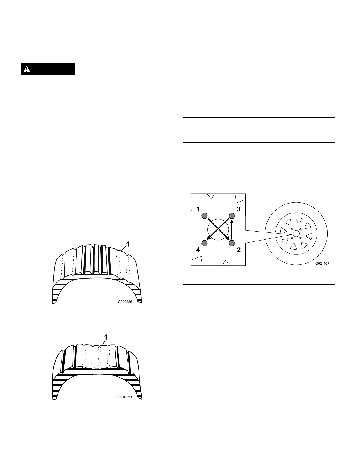
CheckingtheTiresandWheels
G020836
1
2
3
4
G021 107
ServiceInterval:Beforeeachuseordaily—Inspectthetires
andwheels.
Aftereachuse—Torquethelugnutsto108to122
N-m(80to90ft-lb)aftertowing.
WARNING
Failuretomaintaincorrecttirepressuremayresult
intirefailureandlossofcontrol,resultingin
propertydamageandseriousinjuryordeath.
•Checkthetirepressurefrequentlytoensure
properination.Ifthetiresarenotinatedto
thecorrectpressure,theywillwearprematurely.
•Inspectthetireconditionbeforetowingand
afteranyoperatingaccident.
2.Ensurethatthetiresareinatedtothecorrectair
pressure.ThefollowingTireAirPressuretableshows
theappropriateairpressureforthetiresasinstalledat
thefactory.
Important:Alwayschecktheinformation
ontheactualtiresforthecorrectairpressure
requirement.
Important:Themostcommoncauseoftire
troubleisunder-ination.Maintainfullair
pressure.
TireAirPressure
ModelTirepressure
68013C,68014C,68016C,
and68017C
68020C,68021C,and68024CMax241kPa(35psi)
Max414kPa(60psi)
TheDOTtireinformationislocatedontheside
ofeachtire.Thisinformationgivesloadandspeed
ratings.Replacementtiresshouldhavethesame
orbetterratings.Formoreinformationgoto
http://www.nhtsa.gov/Vehicle+Safety/Tires.
Note:Thevariousmachinesinthismanualhavedifferent
weights;referto
Specications(page13)toensurethatthe
tiresonyourmachinemeetorexceedtheweightrequirements
ofyourmachine.
1.Visuallyinspectthetiresfordamageandwear(Figure
19andFigure20)
Figure19
3.Ensurethatthewheellugnutsaretorquedto108to
122N-m(80to90ft-lb).Checkthetorqueofthe
wheellugnutsinitiallyandaftertowing.
Note:Torquethelugnutsinthesequenceshownin
Figure21.
Figure21
1.Exampleoftirewearcausedbyunderination
1.Exampleoftirewearcausedbyoverination
Figure20
14
Page 15
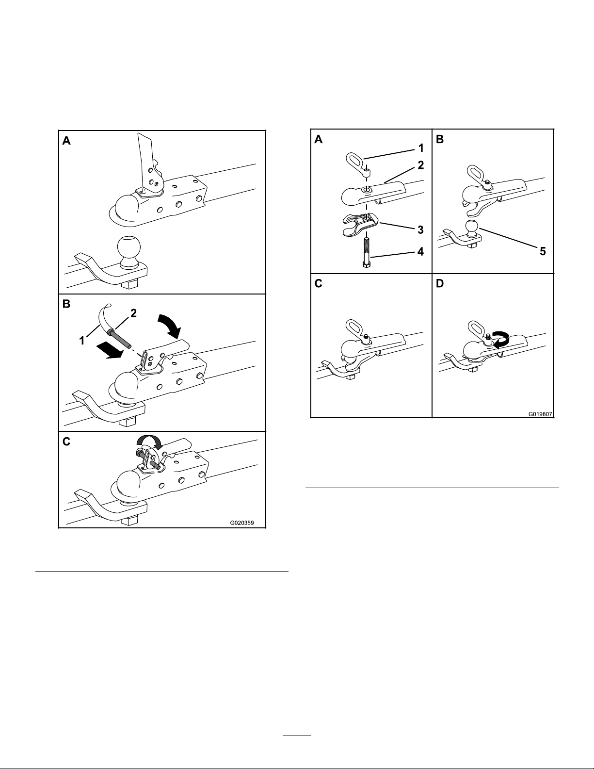
HitchingaMachinewithaStampedBall
A
B
C
G020359
2
1
A
B
D
G019807
5
1
2
3
4
Coupler
HitchingaMachinewithaForgedBall
Coupler
1.Applychassisgreasetothesocketofthecouplerand
theareaoftheclampthatcontactstheball.Oilthe
pivotpointsandslidingsurfacesofthecouplerwith
SAE30motoroil.
2.Openthecouplerlatch(Figure22).
1.Applyremovablethread-lockingcompoundtothe
threadsofthecouplerbolttopreventthecoupler
handlefromcomingloose(Figure23).
Important:Applythread-lockingcompoundas
neededinthefuture.
Figure22
1.Bail
3.Positionthecouplerontopofthehitchball(Figure22).
4.Closethecouplerlatch(
5.Openthebailonthesafetypinandinsertthepin
6.Rotatethefreeendofthebailovertheendofthesafety
7.Connectthewireplugofthetowvehicletothewire
2.Safetypin
throughtheholeinthelatch(Figure22).
pinthatisprotrudingthroughthelatch(Figure22).
plugofthemachine;referto
WireHarness(page17).
Figure22).
ConnectingtheLighting
Figure23
1.Couplerhandle
2.Coupler
3.Clamp
4.Bolt
5.Hitchball
2.Applychassisgreasetothesocketofthecouplerand
theareaoftheclampthatcontactstheball.
3.Pushthecouplerboltupthroughthecouplerclamp
andthecouplertop,andconnectthecouplerhandleto
thebolt(
Figure23).
4.Positionthecouplersothesocketisontopofthehitch
ballandtheclampisundertheball.
5.Turnthecouplerhandleclockwisetothreaditontothe
boltuntilitissecure(Figure23).
Note:Useawrenchtokeeptheboltfromspinning.
6.Connectthewireplugofthetowvehicletothewire
plugofthemachine;referto
ConnectingtheLighting
WireHarness(page17).
15
Page 16
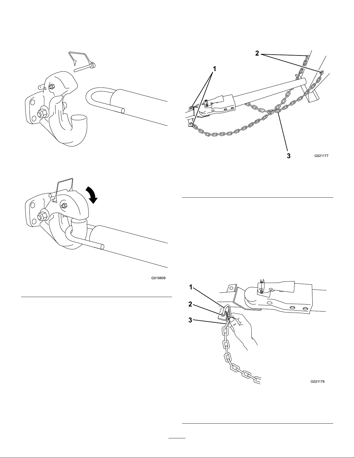
HitchingaMachinewithaPintleHitch
G019809
1
2
3
G021 177
G021 178
1
2
3
TowPole
1.Removethepinfromthepintlehitchandopenit
(Figure24).
2.Crossbothlengthsofchainunderthetowpole.
Note:Crossingthechainsdecreasesthechancesof
thefrontofthemachinedroppingtothegroundifthe
hitchdoesnotholdtheconnection.
Figure25
1.Connectinglinks3.Chaincrossedundertow
2.Keyholesinfrontpost
pole
3.Connecteachlengthofchaintothesafetychain
mountingpointonthetowvehiclewiththeconnecting
links(Figure26).
Important:Ensurethatthechainhasenough
slackforturningaroundcornerswhentowingthe
machine.
Note:Stowtheexcesschaininsidethebottomofthe
frontpostbypushingitintothekeyholesandlatching
theappropriatelinksintothekeyholeslots.
Figure24
2.Positiontheringonthetowpoleontothehookofthe
pintlehitch(Figure24).
3.Closethetopofthepintlehitchandsecureitwiththe
pin(Figure24).
4.Connectthewireplugofthetowvehicletothewire
plugofthemachine;refertoConnectingtheLighting
WireHarness(page17).
ConnectingtheSafetyChainstothe
TowVehicle
Connectthesafetychaintothemachineandthetowvehicle
asfollows:
1.Pullthesafetychainthroughtheslotsinthekeyholes
locatedinthefrontpostofthemachine,sothatthe
lengthsoneachsideareequal(
Figure25).
Figure26
1.Connectinglink3.Chainlink
2.Safetychainmounting
pointontowvehicle
16
Page 17
ConnectingtheLightingWireHarness
G020828
G020019
1
1 2
3
4
3
5
6
5
G020020
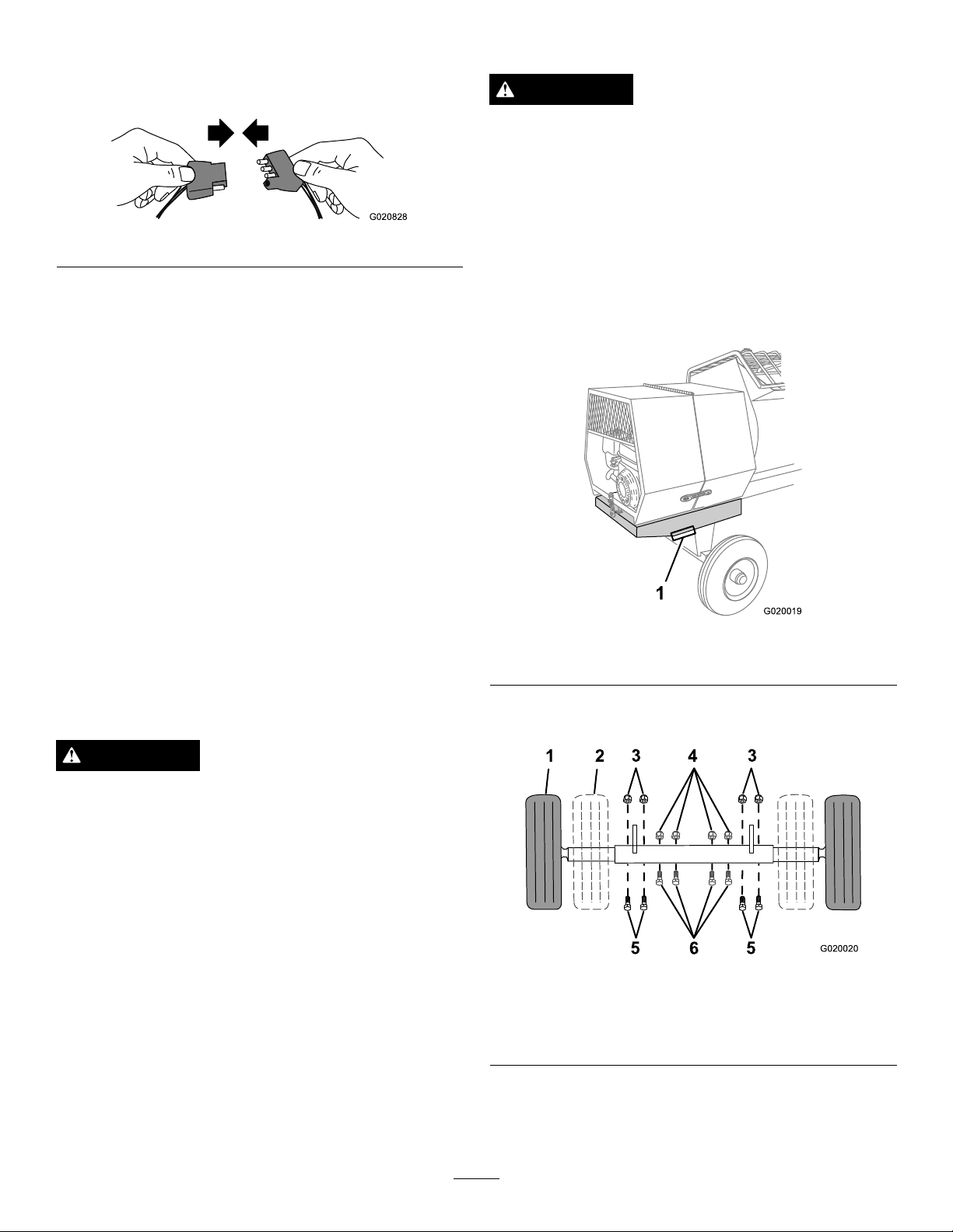
AdjustingtheAxleWidth
Connecttheelectricalplugofthemachinewiththeelectrical
plugofthetowvehicle,asshowninFigure27.
Figure27
Note:Themachineusesastandard4-atplug.Ifyourtow
vehiclehasadifferenttypeofplug,obtainanadapterfroman
automotivepartsstore.
Important:Routinelycheckthelightstoensurethat
theyareworkingproperly,includingthetaillights,brake
lights,andeachappropriateturnsignal.
CheckingtheLights
•Ensurethatthetaillightsofthemachineilluminatewhen
youturnontheheadlightsoftowvehicle.
•Ensurethatthebrakelightsofthemachineilluminate
whenyoupressthebrakepedalofthetowvehicle.
WARNING
Mechanicalorhydraulicjacksmayfailtosupport
themachineandcauseseriousinjury.
Usejackstandswhensupportingthemachine.
1.Alignajackwithanadequateliftheightandweight
capacityundertheaxle;refertoSpecications(page
13).
2.Liftthemachineuntilthetiresareofftheground.
3.Useajackstandateachsupportpointontherear
frameextension(
Figure28).
•Ensurethattheappropriateturnsignalasheswhenyou
operatethecorrespondingturnsignalofthetowvehicle.
ExtendingtheAxle—Belt-drive Models
Models68013C,68014C,68016C,68017C,68020C,and
68021C
WARNING
Themachineisnotstablewhentowingitwiththe
axleinthenarrowposition.
Towthemachinewiththeaxleinthewideposition.
Important:Adjusttheaxletothenarrowpositiononly
tomovethemachinethroughanarrowaccesspoint,
suchasthegateofafenceorthedoorwayofabuilding.
PreparingtoChangetheAxleWidth
1.Movethemachinetoaleveljob-sitesurface.
2.Disconnectthemachinefromthetowvehicle.
3.Chockthetires.
Figure28
1.Supportpoint(2)
4.Removetheboltsandnutsthatsecuretheinneraxleto
theouteraxle(Figure29).
Figure29
1.Wideposition(towing)4.Nut(narrowposition)
2.Narrowposition
3.Nut(wideposition)6.Bolt(narrowposition)
5.Bolt(wideposition)
4.Ensurethatthedrumisemptyandinthemixposition
(upright).
5.Ensurethatthedrumlatchisengagedandthatthe
drumdoesnotrotatetowardthedumpposition.
5.Aligntheinneraxletothedesiredpositionasfollows:
17
Page 18
•Slideeachsideoftheaxleinwardtothenarrow
A
B
D
1
G019879
2
3
4
1
position(Figure29).
•Slideeachsideoftheaxleoutwardtothewide
(tow)position(Figure29).
6.Aligntheholesoftheinneraxlewiththeholesofthe
outeraxle.
7.Inserttheboltsthroughtheaxleholes(
8.Threadthenutsontothebolts,andtorquethenuts
to87N-m(64ft-lb).
Figure29).
TowingtheMachine
WARNING
•Ensurethatthepaddlesareinplaceandingood
condition.
•Checkthefuelandoillevelsoftheengine.
•Whenpreparingtomixmaterial:
1.Movethemachinetoaleveljob-sitesurface.
2.Removethemachinefromthetowvehicle.
3.Chockthefrontandbackofthetirestoprevent
themachinefrommoving.
4.Ensurethatthedrumisinthemixposition
(upright).
5.Ensurethatthedrumlatchisengagedandthatthe
drumdoesnotrotatetowardthedumpposition.
Towingthemachineathighspeedincreasesthe
riskofahitchmalfunctionandtirefailure.Higher
speedsalsoincreasethemomentumofthemachine
andbrakingdistance.Ifthemachinebecomes
detachedfromthetowvehicleathighspeed,it
couldcausedamagetoproperty,orinjuryordeath
tobystanders.
Donotexceed88km/h(55mph)whentowingthe
machine.Forpoorroadconditionsorinclement
weather,reducespeedaccordingly .
WARNING
Towingthemachinewithmaterialinthedrum
increasestheriskofahitchmalfunctionandtire
failure.Inaddition,materialcouldbounceoutof
thedrumandhitothervehiclesand/orpeople.
Materialinthedrumincreasestheweight,which
affectsmomentumandbrakingdistance.
Donottowthemachinewithmaterialinthedrum.
•ReviewandunderstandSafeOperatingPractices(page4).
•Testthebrakesofthetowvehiclebeforetowing.
•Avoidsuddenstartsandstopswhiletowingthemachine.
OpeningandClosingtheCowl
OpeningtheCowl
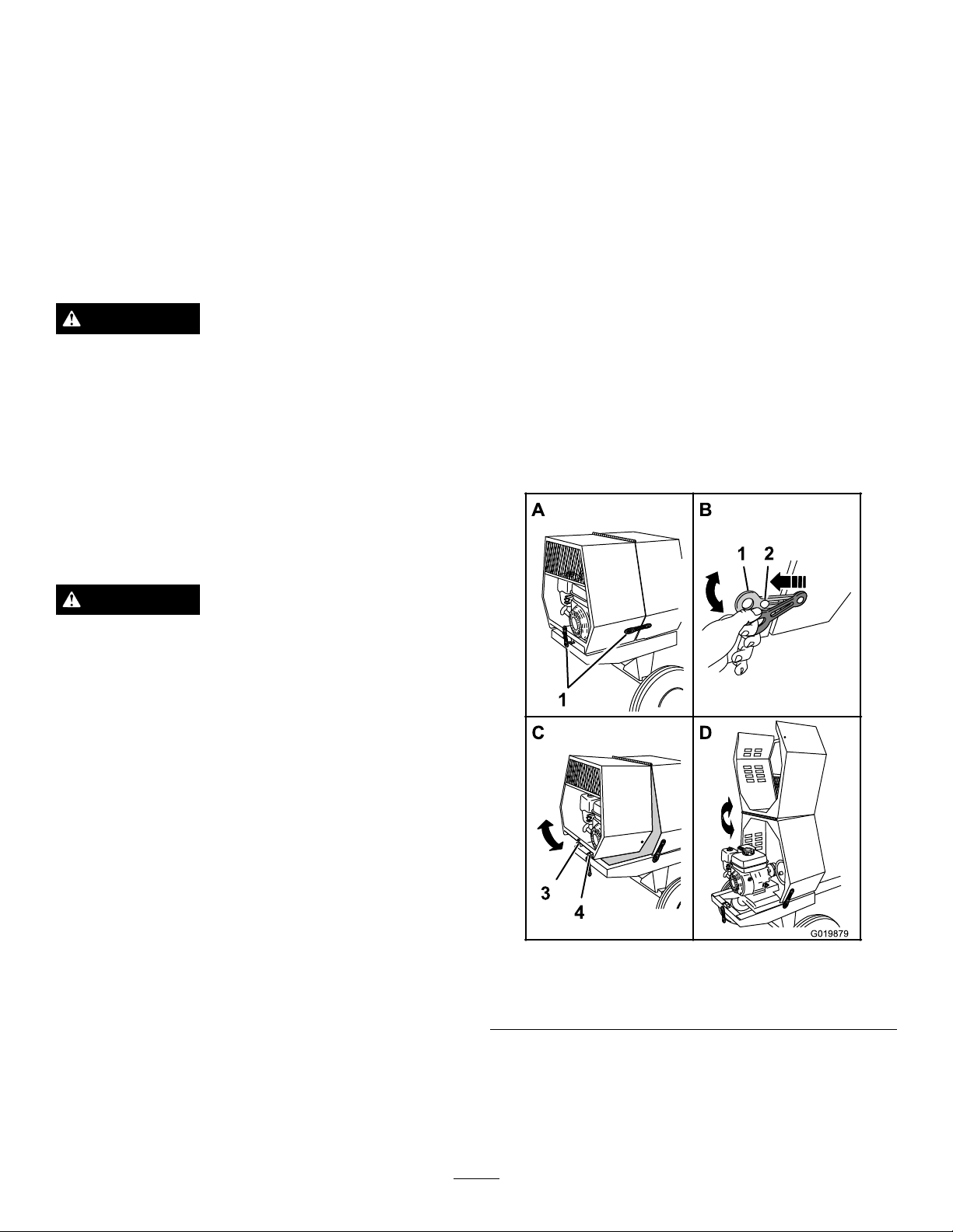
1.Atthesideofthemachinewherethefrontcowland
rearcowlmeet,grasptheringofthelatchandpullit
offfromthelatchanchorontherearcowl(Figure30).
PreparingtoUsetheMachine
•Reviewallofthesafetydecalsonthemachine.
•Useahard-hat,hearingprotection,ashirtwithlong
sleevesbuttonedatthewrists,tight-ttinggloveswithout
drawstringsorloosecuffs,eyeprotection,andadust
maskorrespirator.Ameshvisoralonedoesnotprovide
sufcienteyeprotection;supplementwithprotective
glasses.
•Ensurethatyouarefamiliarwiththesafetyregulations
andshutdownproceduresdescribedintheOperator’ s
ManualandtheEngineOwner’ sManual.
•Ensurethatallguardsareinplaceandingoodcondition.
Figure30
1.Latch3.Receiver
2.Latchanchor
2.Repeatstep1ontheoppositesideofthemachine.
3.Atthebackofthemachinewheretherearcowlmeets
theframeofthemachine,grasptheringofthelatch
andpullitofffromthelatchanchoronthecowl
(Figure30).
18
4.V-tting
Page 19
4.Rotatetherearcowlupandforwarduntilitisfully
positionedontopofthefrontcowl(Figure30).
ClosingtheCowl
1.Rotatetherearcowlrearwardanddownuntilthe
receiveratthebottomcenterofthecowlisalignedwith
theV-ttingandushontheframeofthemachine
(Figure30).
2.Atthebackofthemachine,grasptheringofthelatch
andpullitontothelatchanchorontherearcowl.
3.Atthesideofthemachine,grasptheringofthelatch
andpullitontothelatchanchorontherearcowl.
4.Repeatstep3ontheoppositesideofthemachine
(Figure30).
AddingFuel
•Forbestresults,useonlyclean,fresh,unleadedgasoline
withanoctaneratingof87orhigher((R+M)/2rating
method).
•Oxygenatedfuelwithupto10%ethanolor15%MTBE
byvolumeisacceptable.
•Donotuseethanolblendsofgasoline(suchasE15
orE85)withmorethan10%ethanolbyvolume.
Performanceproblemsand/orenginedamagemayresult
whichmaynotbecoveredunderwarranty.
•Donotusegasolinecontainingmethanol.
•Donotstorefueleitherinthefueltankorfuelcontainers
overthewinterunlessafuelstabilizerisused.
•Donotaddoiltogasoline.
DANGER
Incertainconditions,fuelisextremelyammable
andhighlyexplosive.Areorexplosionfromfuel
canburnyouandothersandcandamageproperty.
•Fillthefueltankoutdoors,inanopenarea,when
theengineiscold.Wipeupanyfuelthatspills.
•Neverllthefueltankinsideanenclosedtrailer.
•Donotllthefueltankcompletelyfull.Add
fueltothefueltankuntilthelevelisnohigher
thanthescreenonthelterinthefueltank.
Thisemptyspaceinthetankallowsthefuelto
expand.
DANGER
Incertainconditionsduringfueling,static
electricitycanbereleasedcausingasparkwhich
canignitethefuelvapors.Areorexplosionfrom
fuelcanburnyouandothersandcandamage
property.
•Alwaysplacefuelcontainersonthegroundaway
fromyourvehiclebeforelling.
•Donotllfuelcontainersinsideavehicleoron
atruckortrailerbedbecauseinteriorcarpets
orplastictruckbedlinersmayinsulatethe
containerandslowthelossofanystaticcharge.
•Whenpractical,removefuel-poweredequipment
fromthetruckortrailerandfueltheequipment
withthewheelsontheground.
•Ifthisisnotpossible,thenrefuelsuch
equipmentonatruckortrailerfromaportable
container,ratherthanfromafueldispenser
nozzle.
•Ifafueldispensernozzlemustbeused,keepthe
nozzleincontactwiththerimofthefueltank
orcontaineropeningatalltimesuntilfuelingis
complete.
WARNING
Fuelisharmfulorfatalifswallowed.Long-term
exposuretovaporscancauseseriousinjuryand
illness.
•Avoidprolongedbreathingofvapors.
•Keepyourfaceawayfromthenozzleandthe
fueltankorconditioneropening.
•Keepfuelawayfromyoureyesandskin.
Important:Donotmixoilwithfuel.
RecommendedFuel
UnleadedGasoline
U.S.
Except
U.S.
Pumpoctanerating87orhigher
Researchoctanerating92orhigher
Pumpoctanerating87orhigher
•Neversmokewhenhandlingfuel,andstayaway
fromanopenameorwherefuelfumesmaybe
ignitedbyaspark.
•Storefuelinanapprovedcontainerandkeepit
outofthereachofchildren.Neverbuymore
thana30-daysupplyoffuel.
•Donotoperatewithouttheentireexhaust
systeminplaceandinproperworkingcondition.
UsingFuelStabilizer/Conditioner
Useafuelstabilizer/conditionerinthemachinetokeepthe
fuelfreshduringstorageof90daysorless.Ifyouarestoring
themachineforlonger,drainthefueltank;referto
theMachine(page44).
Important:Donotusefueladditivescontaining
methanolorethanol.
19
Storing
Page 20
Addthecorrectamountoffuelstabilizer/conditionertothe
1
G019799
G020679
1
fuel,andfollowthedirectionsofthemanufacturer.
Note:Fuelstabilizer/conditionerismosteffectivewhen
mixedwithfreshfuel.Tominimizethechanceofvarnish
depositsinthefuelsystem,usefuelstabilizeratalltimes.
FillingtheFuelTank
Model(s)
68013Cand68014C3.1L(0.82USgallons)
68016C,68017C,68020C,
68021C
68024C6.1L(1.61USgallons)
Fueltankcapacity
5.3L(1.40USgallons)
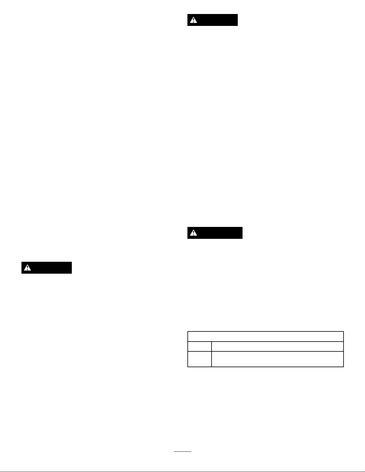
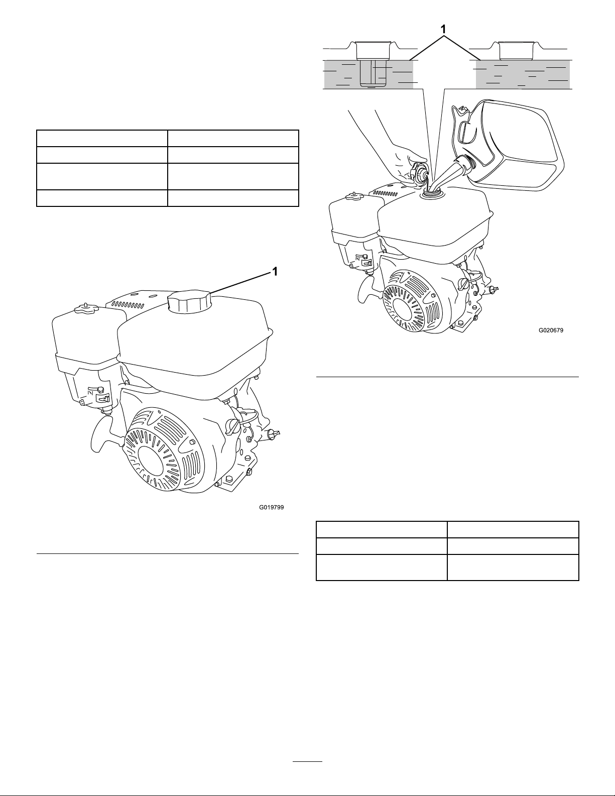
1.Parkthemachineonalevelsurface,stoptheengine,
andallowtheenginetocool.
2.Cleanaroundthefuelcapandremoveit(
Figure31).
Figure32
1.Maximumfuellevel
4.Installthefuelcapsecurely(Figure31).
5.Wipeupanygasolinethatmayhavespilled.
Figure31
1.Fuelcap
3.Addunleadedgasolinetothefueltank,untilthelevel
isatthebottomofthemaximumfuellevel,asshown
inFigure32.
Important:Thisspaceinthetankallowsgasoline
toexpand.Donotllthefueltankcompletelyfull.
CheckingtheEngineOilLevel
ServiceInterval:Beforeeachuseordaily
Important:Use4-cycleengineoilthatmeetsorexceeds
therequirementsforAPIservicecategory
or higher
Model(s)Crankcasecapacity
68013Cand68014C0.58L(0.61USqt)
68016C,68017C,68020C,
68021C,68024C
.
1.1L(1.2USqt)
Important:Iftheoillevelinthecrankcaseistoolow
ortoohighandyouruntheengine,youmaydamage
theengine.Thistypeofdamageisnotcoveredbythe
warranty.
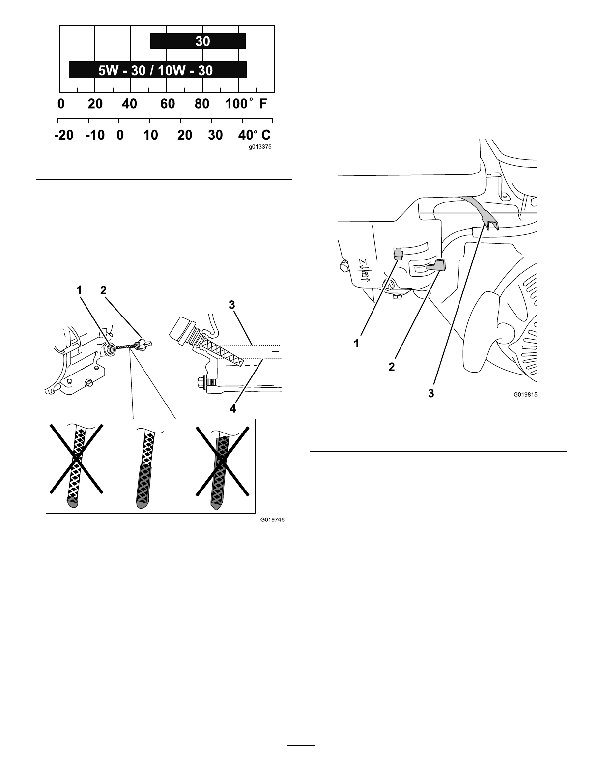
Note:UseSAE10W -30forgeneraluse.Y oucanuse
theotherviscositiesshowninthechartwhentheaverage
temperatureinyourareaiswithintheindicatedrange(
33).
SJ , SL, SM,
Figure
20
Page 21
g013375
0 20 40 60 80 100 F
-20 -10 0 10 20 30 40 C
o
o
30
5W - 30 / 10W - 30
Figure33
1
2
3
4
G019746
G019815
1
2
3
1.Placethemachineonaat,levelsurface,andstopthe
engine.
2.Allowtheenginetocool.
3.Cleanaroundtheoildipstick.
4.Removetheoil-llcap/dipstickandwipetheendclean
(Figure34).
StartingandStoppingthe Engine
StartingtheEngine
1.Ontheengine,movethethrottleleverawayfromthe
Minposition,1/3ofthewaytowardtheMaxposition
(Figure35);refertoThrottleLever(page12).
Figure34
1.Fillport
2.Dipstick
3.Oil-levelupperlimit
4.Oil-levellowerlimit
5.Slidethedipstickfullyintothellportwithout
threadingitintotheport(Figure34).
6.Removethedipstickandlookattheend.Iftheengine
oillevelislow ,slowlypouronlyenoughoilintothell
porttoraisetheleveltotheFullmarkonthedipstick
(
Figure34).
Note:ToroPremiumEngineOilisavailablefrom
yourAuthorizedToroDealer.
7.Replaceandsecurethedipstick(Figure34).
Figure35
1.Chokelever
2.Fuelvalve
3.Throttlelever
2.MovetheleverofthefuelvalvetotheOnposition—all
thewaytotheright(Figure35);refertoFuelValve
(page12).
3.Positionthechokeleverasfollows:
•Tostartacoldengine,movethechokelevertothe
Closedposition—allthewaytotheleft(
referto
ChokeLever(page12).
•Tostartawarmengine,movethechokeleverin
theOpenposition—allthewaytotheright.
4.RotatetheengineswitchtotheOnposition(
35);refertoEngineOn/OffSwitch(page12).
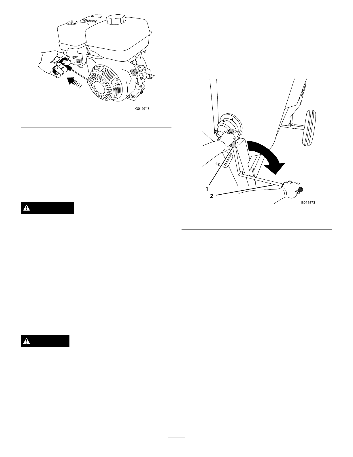
5.Pulltherecoil-starthandlelightlyuntilyoufeel
resistance,thenpullthehandlebriskly .Returnthe
recoil-starthandlegently(
21
Figure36).
Figure35);
Figure
Page 22
G019747
Figure36
G019873
1
2
Note:IfthechokeleverissettotheClosedpositiontostart
theengine,graduallymovethechokeleverbacktowardthe
Openpositionastheenginewarmsup.Iftheenginestalls
orhesitates,movethechokeleverbacktowardtheClosed
positionuntiltheenginerunssmooth.Allowtheengineto
warmup,thenmovethechokelevertotheOpenposition;
referto
ChokeLever(page12).
Usetheclutchlevertocontrolthepowertransmissiontothe
paddlesofthemachine.
ControllingthePaddles—Belt-drive
Models
Models68013C,68014C,68016C,68017C,68020C,and
68021Conly
StoppingtheEngine
WARNING
Inanemergencysituation,stoptheengine
immediately.
Important:Duringnormaloperation,iftheengine
hasbeenworkinghardorishot,letitidleforaminute
beforestoppingtheengine.Thishelpstocoolthe
enginebeforestopping.
1.EnsurethatthechokeleverisintheOffposition
(Figure35);refertoChokeLever(page12).
2.MovethethrottlelevertotheMinposition(
refertoThrottleLever(page12).
3.RotatetheengineswitchtotheOffposition;referto
EngineOn/OffSwitch(page12).
Figure35);
ControllingthePaddles
DANGER
Thismachineiscapableofamputatinghands.
•Stayintheoperator’spositionwhilethemachine
isrunning.
•Keepallbystandersasafedistancefromthe
machine.
•Stopthemachineimmediatelyifanypeopleor
animalsentertheworkarea.
•Neverplaceanypartofyourbodyintoaposition
thatcausesanunsafeoperatingcondition.
Figure37
1.Offposition2.Onposition
22
Page 23
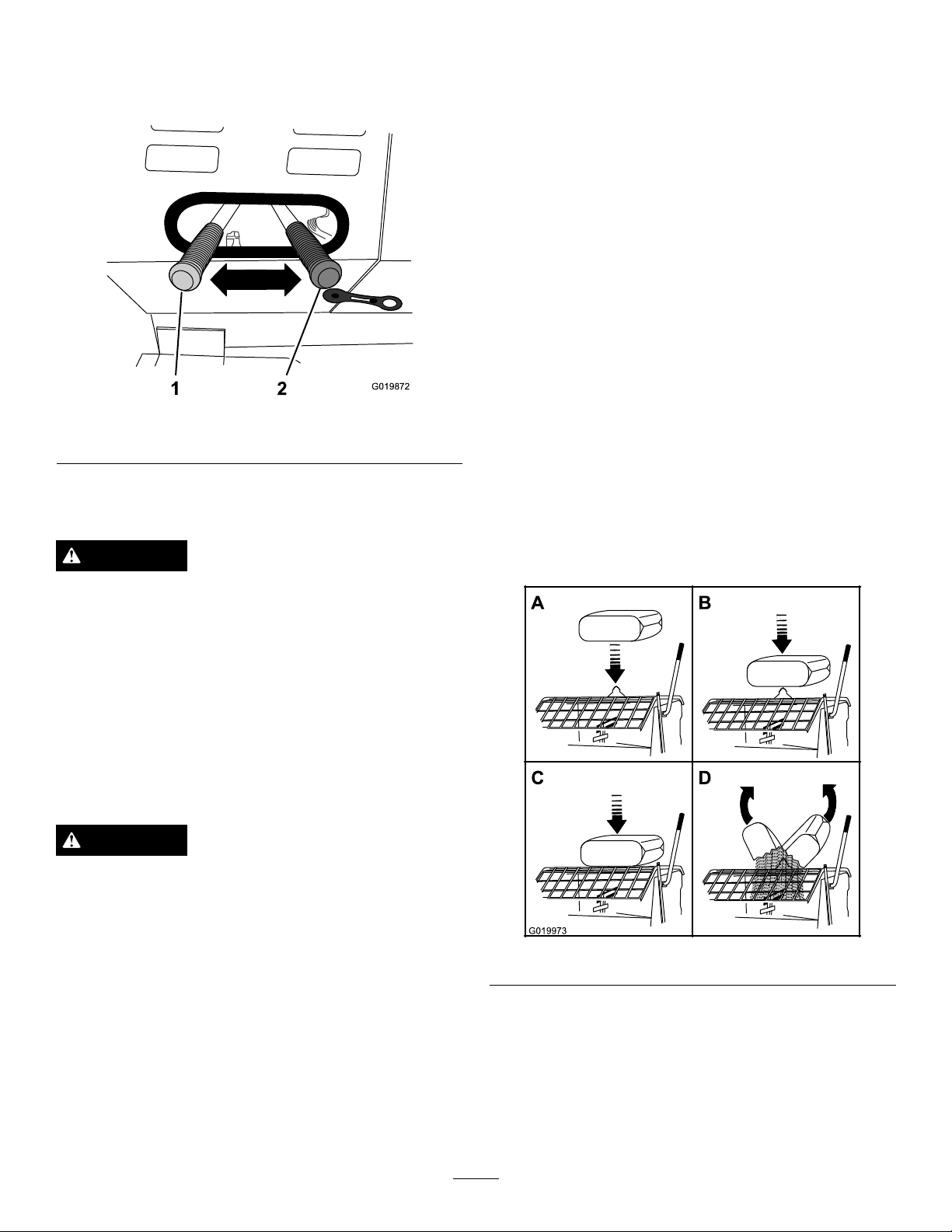
ControllingthePaddles—Gear-case
1
2
G019872
A
B
D
G019973
Model
Model68024Conly
Figure38
1.Onposition2.Offposition
MixingtheMaterial
DANGER
Eyeandskincontactwithconcretematerialsand
breathingthedustinvolvedishazardoustoyour
health.
MixingaBatchofMaterialinthe
Machine
1.Ensurethatthereisnoold,loosematerialinthedrum
thatcancontaminatethebatchofmaterial;referto
CleaningtheDrum(page24)andDumpingtheDrum
(page24),thenreturnthedrumtotheuprightposition.
Note:Ensurethatthedrumisinthemixposition
(upright)andthedrumlatchisengaged.
2.MovetheclutchlevertotheOffposition;referto
ControllingthePaddles(page22).
3.Starttheengine;referto
Note:Allowtheenginetowarm-upat2/3throttle
for1to2minutes.
4.SetthethrottleleverontheenginetotheMaxposition;
referto
5.MovetheclutchlevertotheOnposition;referto
ControllingthePaddles(page22).
6.Addtheingredientsforthebatchasfollows:
A.Pourwaterintothedrumthroughthegratingof
B.Addtheplaster,cement,orotherbindingmaterial.
ThrottleLever(page12).
thedrumguard.
Note:Youcanopenbagsofcement,plaster,and
bindingmaterialsbyloweringthebagontothe
bagsplitter(
Figure39).
StartingtheEngine(page21).
•Ensurethatthereisadequateairventilation.
•Wearadustmasktopreventinhalationofdust
whileusingthemachine;referto
SafeOperating
Practices(page4).
•Avoiddirectcontactofcementandconcrete
materialswithskinandeyes.
DANGER
Contactwiththemixingpaddlescouldcause
damageorinjury.
Neverputyourhandsortoolsinsidethedrumwhile
theengineisrunning.
Important:Donotaddmorematerialthanthebatch
capacityofthemachine;refertoSpecications(page13).
Note:Followthemanufacturer’sinstructionsthatareprinted
onthepackagingoftheproductyouareusing.
Figure39
C.Ifyouareusingsandand/orotherreinforcing
materials,addthemintothedrum.
7.Allowthepaddlestomixthematerialuntilthe
ingredientshaveauniformappearance.
Note:Ifneeded,addwaterorplaster,cement,or
otherbindingmaterialuntiltheconsistencyofthe
batchiscorrect.
23
Page 24
8.Releasethedrumlatchanddumpthedrum;referto
1
2
3
4
G019972
DumpingtheDrum(page24).
UsingtheDrum
DANGER
Note:Allowthemachinetocompletelydischargethe
contentsofthedrum.
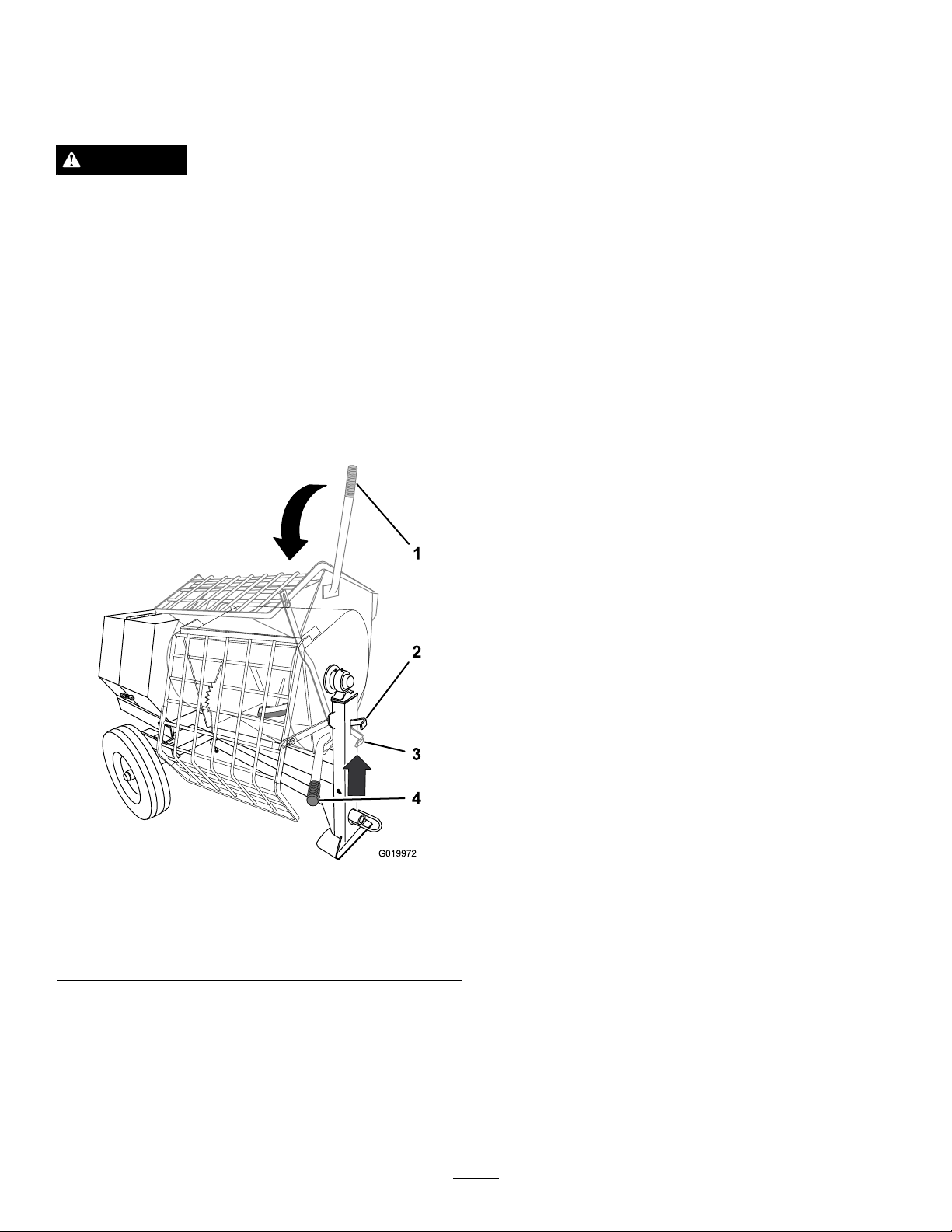
5.Rotatethedumphandleclockwiseuntilthedrum
latchlocksthedrumintheuprightposition(Figure40).
6.Afterdischargingabatchofmaterial,cleanthedrum;
refertoCleaningtheDrum(page24).
Contactwiththemixingpaddlescouldcause
damageorinjury.
Neverputyourhandsinsidethedrumwhilethe
engineisrunning.
DumpingtheDrum
Note:Whendumpingabatchofmaterial,leavetheengine
runningandtheclutchintheOnpositionsotherotating
paddleshelpdischargethematerial.
1.Alignawheelbarroworsimilarcontainerofadequate
capacityinthepathofthedrumopening.
2.Graspthedumphandlewithyourlefthand(Figure40).
Note:Thisstepwillcleanthepaddlesanddrum
betweenbatchesandpreventdriedmaterialfrom
forming,andcontaminatingthenextbatchofmaterial.
CleaningtheDrum
Important:Donotstrikeonthedrumwithashovel,
hammer,oranyotherdevicetoloosenanyaccumulated
driedmaterials.
1.Stoptherotationofthepaddlesbymovingtheclutch
levertotheOffposition;refertoControllingthe
Paddles(page22).
2.RotatetheengineOn/OffswitchtotheOffposition;
referto
3.Ensurethatthedrumisinthemixposition(upright);
refertoDumpingtheDrum(page24),step5.
4.Spraythemachinewithwatertoremoveany
accumulatedmaterial.
5.Starttheengine;refertoStartingtheEngine(page21).
6.Starttherotationofthepaddlesbymovingtheclutch
levertotheOnposition;refertoControllingthe
Paddles(page22).
StoppingtheEngine(page22).
Figure40
1.Dumphandle(mix
position)
2.Drumlatch(release
position)
Note:Whendumpingabatchofmaterial,aligna
wheelbarroworasimilarcontainerofadequatecapacity
beneaththechute.
3.Liftthehandleofthedrumlatch(Figure40).
4.Withbothhandsonthedumphandle,rotateit
counterclockwisetodischargethecontentsofthe
drum(Figure40).
3.Drumlatch(locked
position)
4.Dumphandle(dump
position)
7.Dumpthedrum;refertoDumpingtheDrum(page
24).
AdjustingthePaddleBlades
Note:Adjustingthepaddlebladesisoptional.
1.Stoptheengineandwaitforallmovingpartstostop.
2.Disconnectthewirefromthesparkplug;referto
DisconnectingtheSpark-plugWire(page28).
3.Removethenutsandboltsthatsecurethegratetothe
drum,andremovethegrate(Figure41,Figure42,or
Figure43).
24
Page 25

G022159
Figure41
G022161
G022163
Models68013C,68016C,68020C
Figure43
Model68024C
Figure42
Models68014C,68017C,68021C
25
Page 26
4.Loosenthenutsandboltsthatsecurethepaddleblades
1
2
G022160
1
2
G022162
1
2
G022164
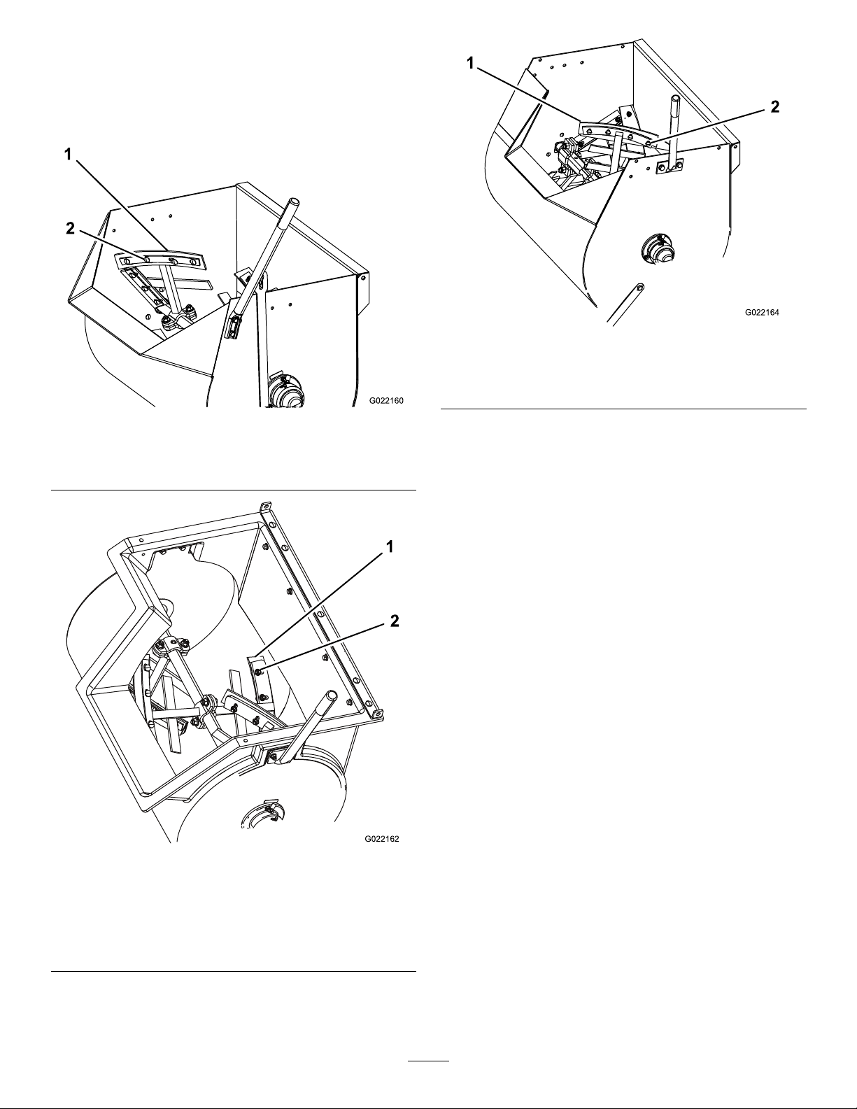
tothepaddles(Figure44,Figure45,orFigure46).
Note:Ifnecessary,tipthedrumtothedumpposition
toaccessthepaddles.
Figure46
Model68024C
1.Paddleblade2.Nutandbolt
Figure44
Models68013C,68016C,68020C
1.Paddleblade2.Nutandbolt
5.Movethepaddlebladestothepreferredposition,and
tightenthenutsandboltstosecurethebladestothe
paddles.
Note:EnsurethattheclutchleverisintheOff
position,androtatethepaddlesasneeded.
6.Installthegratewiththenutsandboltsthatyou
removedinstep3,andtightenthenutsandboltsuntil
theyaresecure.
Figure45
1.Paddleblade2.Nutandbolt
Models68014C,68017C,68021C
26
Page 27

Maintenance
Important:Beforeperforminganymaintenanceprocedures,rststoptheengine,wait5minutestoallowallmoving
partstocometoacompletestopandcool,anddisconnectthespark-plugwire.
RecommendedMaintenanceSchedule(s)
MaintenanceService
Interval
Aftertherst20hours
Aftertherst25hours
Beforeeachuseordaily
Aftereachuse
Every40hours
Every50hours
Every100hours
MaintenanceProcedure
•Changethereduction-caseoil(Models68013Cand68014Conly).
•Changetheengineoil.
•Checkthegear-caseclutch(Model68024Conly).
•Inspectthebeltsandadjustasnecessary.
•Inspectthetiresandwheels.
•Checktheengineoillevel.
•Inspecttheair-cleanerelements.
•Checkthereduction-caseoil(Models68013Cand68014Conly).
•Checktheclutchoperation(Model68024Conly).
•T orquethelugnutsto108to122N-m(80to90ft-lb)aftertowing.
•Cleanthedrumbetweenmixingbatchesofmaterial.
•Lubricatethetrunnions.
•Cleanthemachine.
•Checkthegear-caseoil(Model68024Conly).
•Inspectthebeltsandadjustasnecessary.
•Checktheclutchoperation(Models68013C,68014C,68016C,68017C,68020C,
and68021Conly).
•Cleantheair-cleanerelements.Cleanthemmorefrequentlyindustyoperating
conditions.
•Changetheengineoil.
•Checkthesparkplug.
•Cleanthesparkarrester.
•Cleanthesedimentcup.
•Changethereduction-caseoil(Models68013Cand68014Conly).
Every300hours
Every800hours
Monthly
Yearlyorbeforestorage
Every2years
Important:Refertoyour
•Replacethepaperair-cleanerelement.Replaceitmorefrequentlyindustyoperating
conditions.
•Replacethesparkplug.
•Replacethegear-caseoil(Model68024Conly).
•Lubricatethepillow-blockbearings.
•Cleanthefuelsedimentcup.
•Replacethebelts.
Engine Operator's Man ual
foradditionalmaintenanceprocedures.
27
Page 28
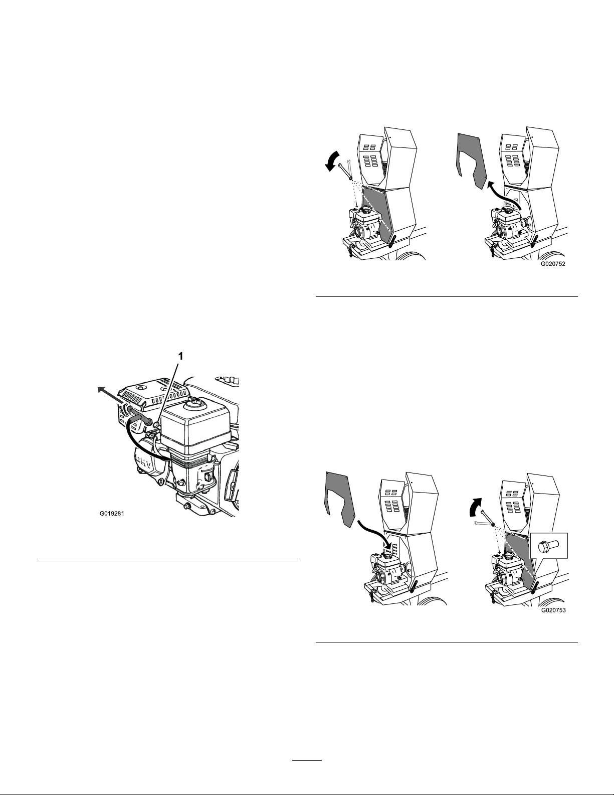
Premaintenance
G019281
1
G020752
G020753
Procedures
PreparingtheMachinefor Maintenance
1.Parkthemachineonalevelsurface.
2.Removethemachinefromthetowvehicle.
3.Chockthetires.
4.Opentherearcowl;refertoOpeningandClosingthe
Cowl(page18).
5.Ensurethattheengineandmuferarecool.
RemovingtheDividerPlate
1.Unlatchandopenthecowl;refertoOpeningtheCowl
(page18).
2.Useawrenchtoremovethe4boltsthatsecurethe
dividerplatetothefrontcowl.
Note:Keeptheboltsforinstallingthedividerplate.
6.Disabletheengine;referto
Spark-plugWire(page28).
Disconnectingthe
DisconnectingtheSpark-plug Wire
Pullthespark-plugwireofftheterminalofthesparkplug
(Figure47).
Figure47
Figure48
3.Toremovethedividerplate,liftitupwardandrotate
itcounterclockwisesothatitclearsvariousengine
components.
InstallingtheDividerPlate
1.Guidethedividerplateintopositionagainstthefront
cowl.
Note:Startwiththedividerplaterotatedslightly
counterclockwise,andthenrotateitclockwisewhile
loweringitintoposition.
Ensurethatthedividerplateisnotbackward.
1.Sparkplug
RemovingandInstallingthe DividerPlate
Youneedtoremovethedividerplatetoprovideaccessbefore
performingsomemaintenanceprocedures.
Note:Model68024Cdoesnothaveadividerplate.
Figure49
2.Aligntheboltholesinthedividerplateandthefront
cowl.
3.Installeachofthe4bolts,andhand-tightenthemto
preventcross-threading.
4.Tightentheboltswithawrenchuntiltheyaresecure.
28
Page 29
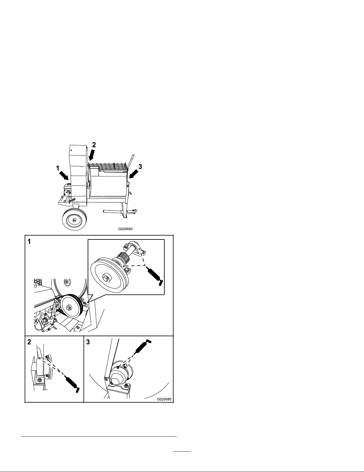
Lubrication
2
3
G020684
1
3
G020685
LubricatingtheBearingsand Seals
ServiceInterval:Aftereachuse—Lubricatethetrunnions.
Monthly—Lubricatethepillow-blockbearings.
Note:Thepillow-blockbearingsareinsidethe
cowl—removethedividerplatetoaccessthem;referto
RemovingtheDividerPlate(page28).
Model68024Cdoesnothaveadividerplate.
GreaseType:#2general-purposelithium-basedgrease.
1.Cleanaroundeachgreasettingwitharagandliftthe
plasticcapoffthegreasetting(
Figure50).
2.Pumpgreaseintoeachttingasfollows:
•Forthepillow-blockbearings,pump1shotof
greaseintoeachtting(Figure50).
•Forthetrunnions,pumpseveralshotsofgrease
intoeachttinguntilitstartstooozeoutofthe
bearinghousing(Figure50).
Important:Pumpgreaseinslowlyandcarefully
topreventdamagetothebearingseals.
3.Wipeupanyexcessgrease.
Figure50
1.Pillow-blockbearings3.Fronttrunnion
2.Reartrunnion
29
Page 30
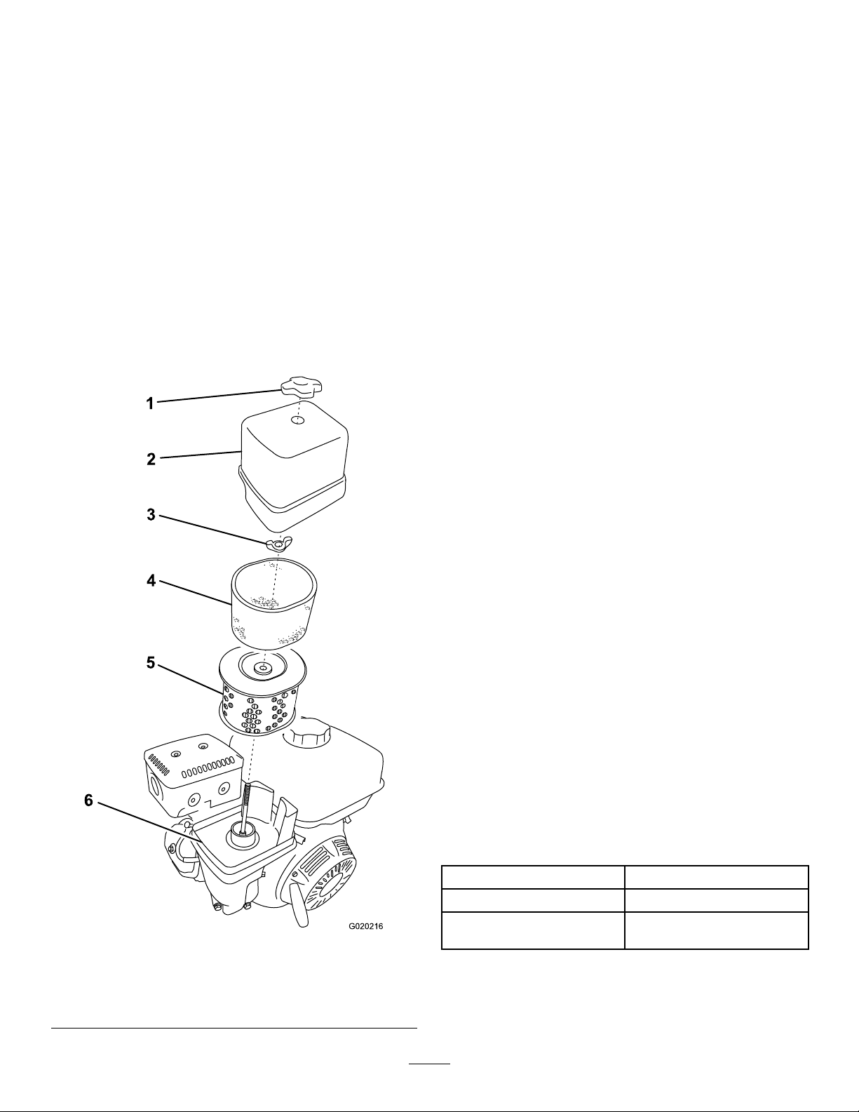
EngineMaintenance
G020216
1
2
3
4
5
6
ServicingtheAirCleaner
ServiceInterval:Beforeeachuseordaily—Inspectthe
air-cleanerelements.
Every50hours—Cleantheair-cleanerelements.Clean
themmorefrequentlyindustyoperatingconditions.
Every300hours/Yearly(whichevercomes
rst)—Replacethepaperair-cleanerelement.Replace
itmorefrequentlyindustyoperatingconditions.
Important:Donotoperatetheenginewithoutthe
air-lterassembly;extremeenginedamagewilloccur.
1.Stoptheengineandwaitforallmovingpartstostop.
2.Disconnectthewirefromthesparkplug;referto
DisconnectingtheSpark-plugWire(page28).
3.Removethenutthatsecuresthecover(Figure51).
4.Removethecover.
Note:Becarefultopreventdirtanddebrisfrom
fallingintothebase.
5.Removethefoamandpaperelementsfromthebase
(Figure51).
6.Removethefoamelementfromthepaperelement
Figure51).
(
7.Inspectthefoamandpaperelements,andreplacethem
iftheyaredamagedorexcessivelydirty.
8.Ifthepaperelementisexcessivelydirty,replaceit.
Note:Nevertrytobrushdirtoffthepaperelement;
brushingforcesthedirtintothebers.
9.Cleanthefoamelementinwarm,soapywaterorina
nonammablesolvent.
Note:Donotusefueltocleanthefoamelement
becauseitcouldcreateariskofreorexplosion.
10.Rinseanddrythefoamelementthoroughly.
11.Dipthefoamelementincleanengineoil,thensqueeze
outtheexcessoil.
Note:Excessoilinthefoamelementrestrictstheair
owthroughtheelementandmayreachthepaper
lterandclogit.
12.Wipedirtfromthebaseandthecoverwithamoistrag.
Note:Becarefultopreventdirtanddebrisfrom
enteringtheairductleadingtothecarburetor.
13.Installtheair-cleanerelementsandensurethattheyare
properlypositioned.
14.Securelyinstallthecoverwiththenut.
ChangingtheEngineOil
ServiceInterval:Aftertherst25hours
Every100hours
ToroPremiumEngineOilisavailablefromyourAuthorized
ToroDealer.
Important:Use4-cycleengineoilthatmeetsorexceeds
therequirementsforAPIservicecategory
or higher
.
SJ , SL, SM,
Model(s)Crankcasecapacity
68012C,68014C0.58L(0.61USqt)
68016C,68017C,68020C,
Figure51
1.Covernut
2.Cover
3.Wingnut6.Base
4.Foamelement
5.Paperelement
68021C,68024C
Important:Iftheoillevelinthecrankcaseistoolow
ortoohighandyouruntheengine,youmaydamage
theengine.Thistypeofdamageisnotcoveredbythe
warranty.
30
1.1L(1.2USqt)
Page 31
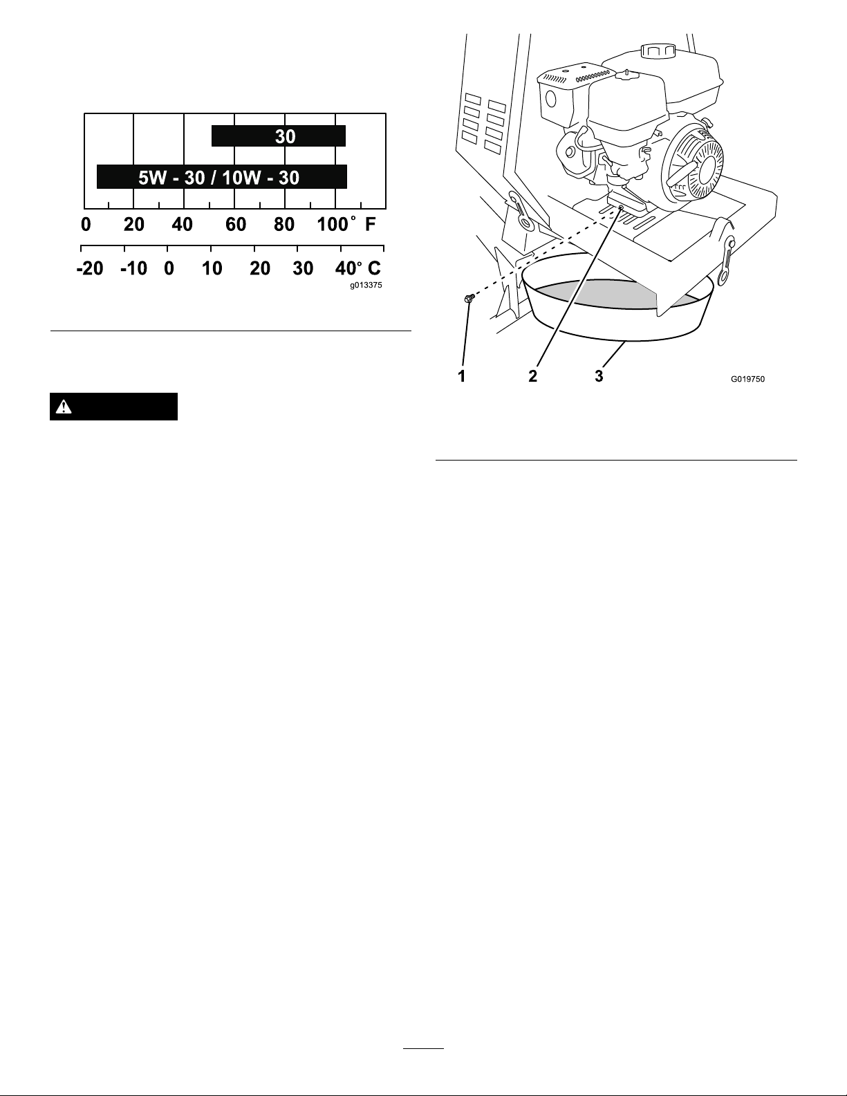
Note:UseSAE10W -30forgeneraluse.Y oucanuse
g013375
0 20 40 60 80 100 F
-20 -10 0 10 20 30 40 C
o
o
30
5W - 30 / 10W - 30
1
2
3
G019750
theotherviscositiesshowninthechartwhentheaverage
temperatureinyourareaiswithintheindicatedrange(Figure
52).
Figure52
DrainingtheEngineOil
WARNING
Oilmaybehotaftertheenginehasbeenrun,and
contactwithhotoilcancauseseverepersonalinjury.
Figure53
1.Oildrainplug3.Oildrainpan
2.Oildrainhole
Avoidcontactingthehotengineoilwhenyoudrain
it.
1.Stoptheengineandwaitforallmovingpartstostop.
2.Disconnectthewirefromthesparkplug;referto
DisconnectingtheSpark-plugWire(page28).
3.Placeadrainpanundertheoildrainholeoftheengine
Figure53).
(
4.Removethedrainplugandcatchtheoilintheoildrain
pan(Figure53).
5.Whentheoilhasdrainedcompletely,installthedrain
plugwithanewwasher(Figure53).
Note:Disposeoftheusedoilatacertiedrecycling
center.
FillingtheEngineCrankcasewithOil
1.Removethedipstick(Figure54)andslowlypouroil
intothellholeuntiltheoilreachestheupper-limit
mark(bottomedgeoftheoil-llhole)onthedipstick.
31
Page 32
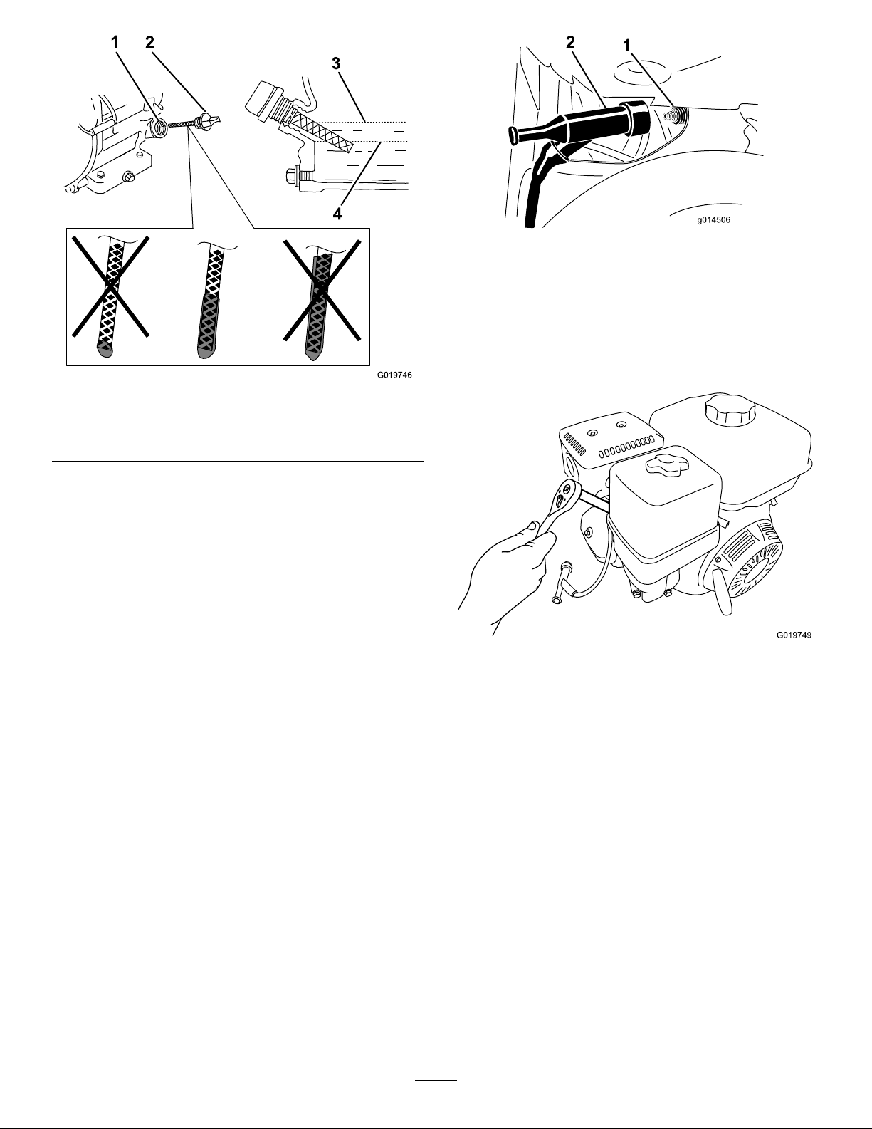
1
2
3
4
G019746
Figure55
G019749
Figure54
1.Oilllhole3.Oil-levelupperlimit
2.Dipstick
4.Oil-levellowerlimit
2.Replaceandsecurethedipstick.
3.Wipeupanyspilledoil.
ServicingtheSparkPlug
ServiceInterval:Every100hours/Every6months
(whichevercomesrst)—Checkthe
sparkplug.
Every300hours/Yearly(whichevercomes
rst)—Replacethesparkplug.
1.Sparkplug
2.Wire
4.Cleanaroundthesparkplug.
5.Rotatethesparkplugcounterclockwiseusinga20mm
(13/16inch)spark-plugwrenchtoremovetheplug
andthesealingwasher(Figure56).
Figure56
Type:NGKBPR6ESorequivalent
Gap:0.7to0.8mm(0.028to0.031inch)
Note:Usea20mm(13/16inch)spark-plugwrenchfor
removingandinstallingthesparkplug.
RemovingtheSparkPlug
1.Parkthemachineonalevelsurfaceandturnoffthe
engine;refertoStoppingtheEngine(page22).
2.Ensurethatthemachinesurfacesarecool.
3.Pullthespark-plugwireofftheterminalofthespark
plug(
Figure55).
CheckingtheSparkPlug
Note:Useagappingtool/feelergaugetocheckandadjust
thegap.Installanewsparkplugifnecessary.
1.Lookatthecenterofthesparkplug(
seelightbrownorgrayontheinsulator,theengineis
operatingproperly.
Important:Nevercleanthesparkplug.Always
replacethesparkplugwhenithasablackcoating,
wornelectrodes,anoilylm,orcracks.
32
Figure57).Ifyou
Page 33
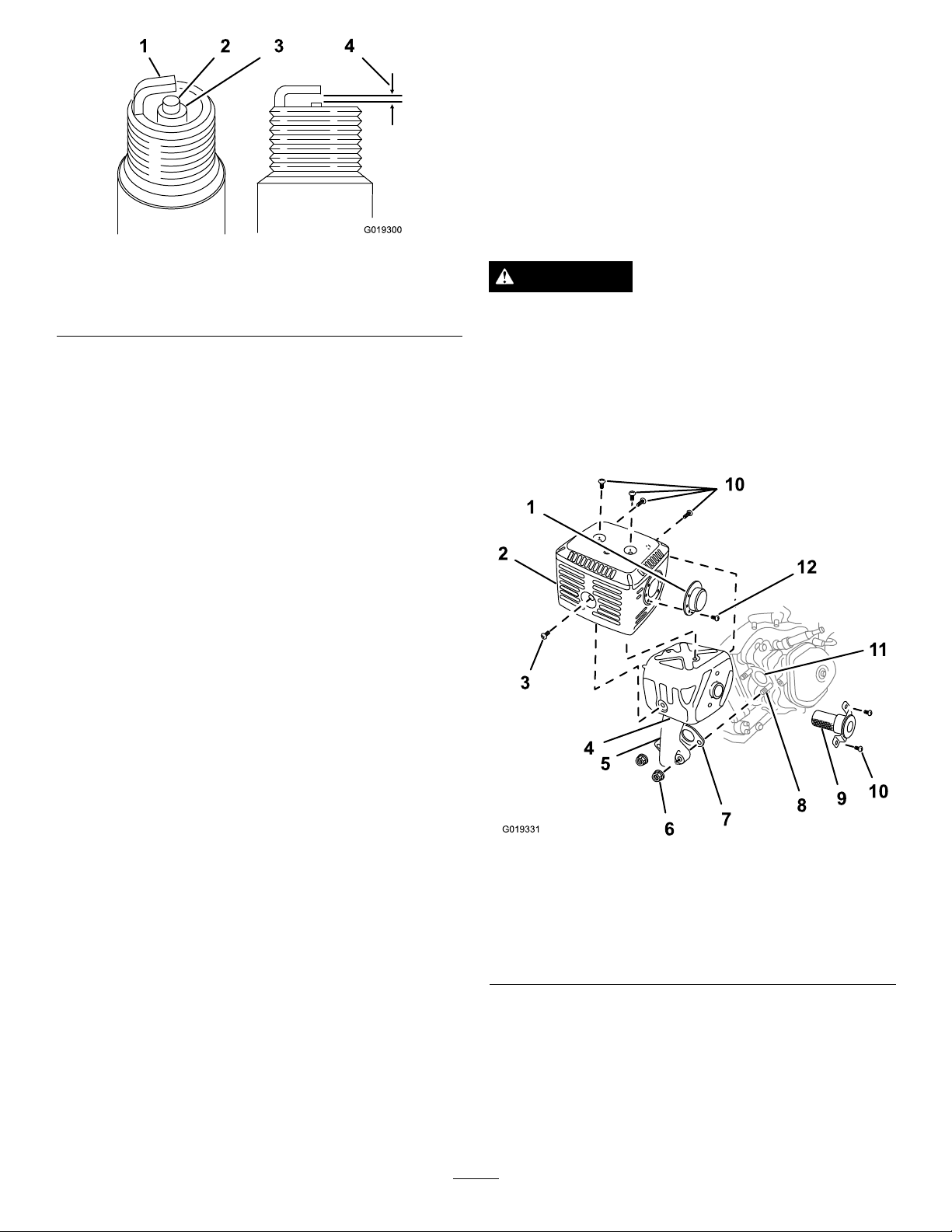
G019300
1 2
4
3
Figure57
G019331
10
10
1
2
3
4
5
6
7
8
9
11
12
ServicingtheSparkArrester
CleaningtheSparkArrester
ServiceInterval:Every100hours
Note:Asparkarresterisavailableasanoption.Ifyou
requireasparkarrester,contactyourAuthorizedToroService
Dealer.
GenuineTorosparkarrestersareapprovedbytheUSDA
ForestryService.
1.Sideelectrode
2.Centerelectrode4.0.7to0.8mm(0.028to
3.Insulator
0.031inch)gap
2.Useagappingtoolforsparkplugsorafeelergaugeto
measurethegapbetweenthesideelectrodeandcenter
electrode(Figure57).
3.Ifthegapisnotwithinthespeciedrange,dothe
following:
A.Ifthegapistoosmall,carefullybendtheside
electrodeawayfromthecenterelectrodeuntil
thegapbetweentheelectrodesis0.7to0.8mm
(0.028to0.031inch).
B.Ifthegapistoolarge,carefullybendtheside
electrodetowardthecenterelectrodeuntilthe
gapbetweentheelectrodesis0.7to0.8mm(0.028
to0.031inch).
InstallingtheSparkPlug
Important:Ensurethatthegapbetweenthesideand
centerelectrodesiscorrectbeforeinstallingthespark
plug.
WARNING
Iftheenginehasbeenrunning,themuferwillbe
hot.
1.Removethedividerplate;refertoRemovingthe
DividerPlate(page28).
Note:Model68024Cdoesnothaveadividerplate.
2.Removethe2nuts(8mm)andremovethemufer
fromthecylinder(
Figure58).
1.Threadthesparkplugclockwiseintothespark-plug
holebyhand.
Note:Avoidcross-threadingthesparkplugwiththe
threadsofthespark-plughole.
2.Rotatesparkplugclockwiseusinga20mm(13/16
inch)spark-plugwrenchuntiltheplugandsealing
washerareseated(Figure56).
3.Tightenthesparkplugasfollows:
•Wheninstallinganin-servicesparkplug,tighten
thepluganadditional1/8to1/4turn.
•Wheninstallinganewsparkplug,tightentheplug
anadditional1/2turn.
4.Pushthespark-plugwireontotheterminalofthespark
plug(
Figure55).
Figure58
1.Deector(if
applicable)
2.Protector
3.Screw(6mm)7.Gasket
4.Mufer8.Bolt(8mm)12.Screw(4mm)
5.Exhaustpipe
6.Nut,8mm(2)10.Screws(5mm)
3.Removethe3screws(4mm)fromtheexhaust
deectorandremovethedeector(
4.Removethescrews(5mmand6mm)fromthemufer
protector,andremovethemuferprotector(Figure
58).
5.Removethescrew(4mm)fromthesparkarresterand
removethesparkarresterfromthemufer(Figure58).
33
9.Sparkarrester
11.Exhaustport
Figure58).
Page 34
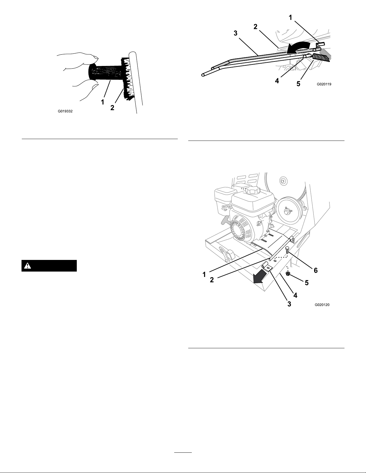
6.Useabrushtocarefullyremovecarbondepositsfrom
1
2
G019332
3
2
4
1
5
G0201 19
G020120
1
2
3
5
6
4
thespark-arresterscreen(Figure59).
Note:Replacethesparkarresterifithasbreaksor
holes.
Figure60
Figure59
1.Screen
2.Brush
7.Installthesparkarrester,muferprotector,exhaust
deector,andmuferinthereverseorderof
disassembly.
8.Installthedividerplate;refertoInstallingtheDivider
Plate(page28).
RemovingandInstallingthe Engine
Models68013C,68014C,68016C,68017C,68020C,and
68021Conly
RemovingtheEngine
WARNING
1.Anchorbracket
2.Enginedeck
3.Spring-removaltool(T oro
part92-5771)
4.Spring-removaltool
(springremoved)
5.Spring(springremoved)
7.Removetheboltandnutthatsecuretherearbracket
fortheenginedeckhingetotheframeofthemachine
(Figure61).
Thespringisundertensionwheninstalledandcan
causepersonalinjury.
Becarefulwhenremovingthespring.
1.Parkthemachineonalevelsurfaceandstoptheengine;
refertoStoppingtheEngine(page22).
2.Ensurethattheengineandtheexhaustsystemsurfaces
arecool.
3.Removethedividerplate;referto
InstallingtheDividerPlate(page28).
4.Removethebeltguide;referto
(page40).
5.Removethebelts;refertoRemovingtheBelts(page
40).
6.Usingaspring-removaltool(Toropart92-5771),
removethespringfromtheanchorbracketonthe
enginedeck(
Figure60).
Note:Leavetheotherendofthespringattachedto
theframeofthemachine.
RemovingtheBelts
Figure61
1.Enginedeck4.Frame
2.Pivot5.Nut
3.Rearhingebracket6.Bolt
Removingand
8.Liftupontherearedgeoftheenginedeckandremove
thehingebracket(Figure61).
9.Slidetheenginedeckrearwardandoutfromthe
forwardhingebracket(Figure62).
Note:Donotremovetheforwardhingebracket.
34
Page 35
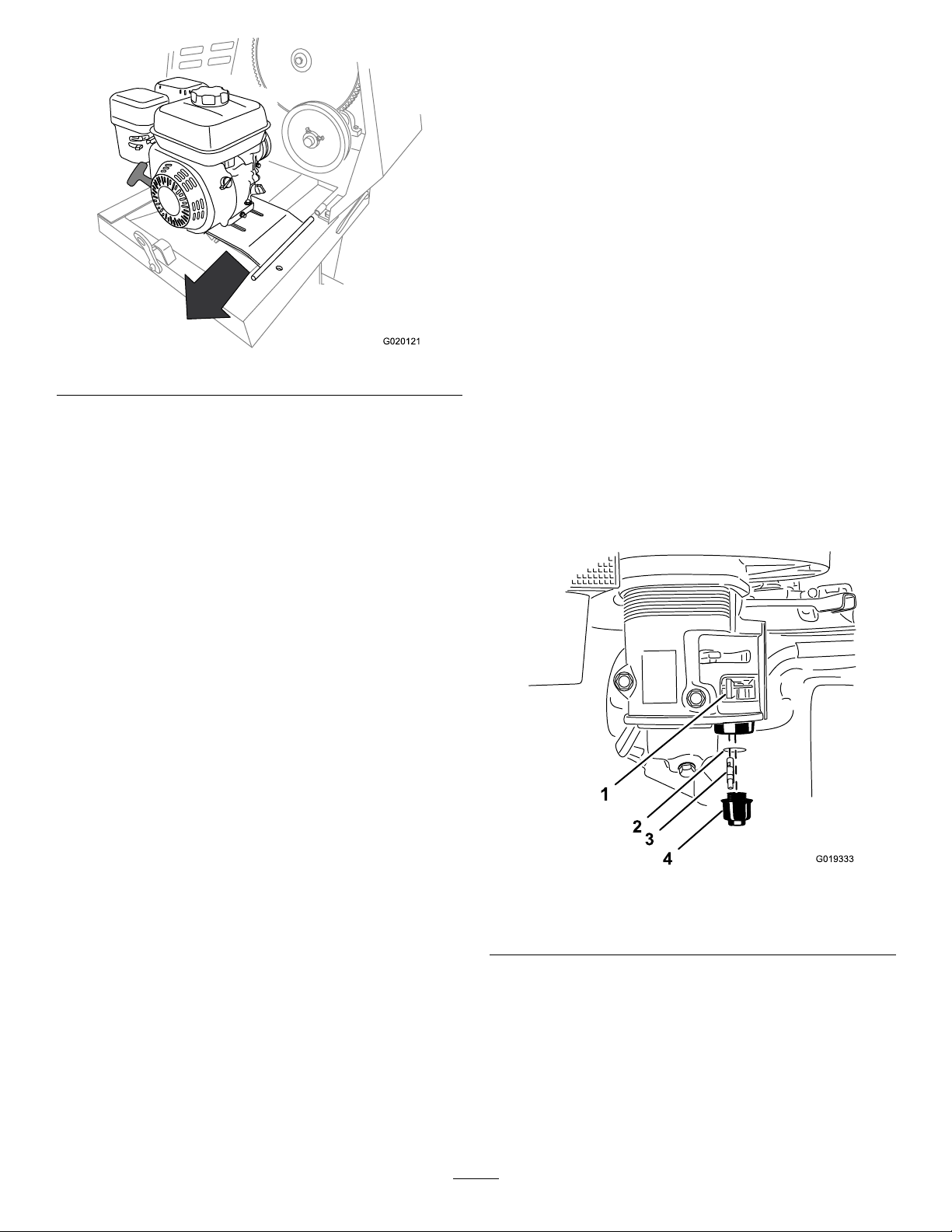
G020121
Figure62
2
3
4
1
G019333
10.Removetheengineandenginedeckfromthemachine
Figure62).
(
InstallingtheEngine
1.Aligntheengineandenginedecktotherearframeof
themachine.
FuelSystem
Maintenance
ServicingtheFuelSystem
CleaningtheSedimentCup
ServiceInterval:Every100hours/Every6months
(whichevercomesrst)—Cleanthe
sedimentcup.
Yearlyorbeforestorage—Cleanthefuelsedimentcup.
Underneaththefuelvalveisasedimentcuptocatchdirtin
thefuel.
1.Parkthemachineonalevelsurfaceandstoptheengine;
refertoStoppingtheEngine(page22).
2.Ensurethattheengineandtheexhaustsystemsurfaces
arecool.
3.MovetheleverofthefuelvalvetotheOffposition,all
thewaytotheleft(Figure63).
4.Unscrewthesedimentcup(Figure63).
5.RemovethefuellterandO-ring(Figure63).
Note:DonotmisplacetheO-ring.
Note:Thedrivepulleyontheenginemustalign
forward.
2.Alignthepivotontheenginedeckwiththeforward
hingebracket(Figure62).
3.Slidetheenginedeckforwardandthepivotintothe
forwardhingebracket(Figure62).
4.Aligntherearhingebracketwiththepivotonthe
engine-deckhinge(Figure62).
5.Liftupontherearedgeoftheenginedeckandslipthe
hingebracketontothepivot.
6.Securetherearbrackettotheframeofthemachine
usingtheboltandnut(Figure61)removedinstep7of
RemovingtheEngine(page34).
7.Usingaspring-removaltool,(T oropart92-5771),
installthetensionspringtotheanchorbracketonthe
enginedeck(
8.Installthebeltsandbeltguide;refertoInstallingthe
Belts(page41).
9.Adjustthebeltguide;refertoAdjustingtheBeltGuide
(page41).
10.Installthedividerplate;referto
InstallingtheDividerPlate(page28).
Figure60).
Removingand
Figure63
1.Fuelvalve(Off)3.Fuellter
2.O-ring4.Sedimentcup
Note:DonotcleantheO-ringinsolvent.
6.Cleanthefuellterandsedimentcupusinga
nonammablesolvent,anddryitcarefully.
7.WipetheO-ringwithaclean,drycloth.
8.Installthefuellterinthebottomofthecarburetor
Figure63).
(
9.AligntheO-ringintothegrooveinthesedimentcup
andinstallthesedimentcuptofuelvalvehousing.
35
Page 36
10.MovetheleverofthefuelvalvetotheOnposition(all
1
2
G020122
1
2
4
3
G019974
thewaytotheright)andcheckforleaks.Ifitleaks,
replacetheO-ring.
DriveSystem
Maintenance
DrainingtheFuelTank
1.Removetheengine;refertoRemovingtheEngine
(page34).
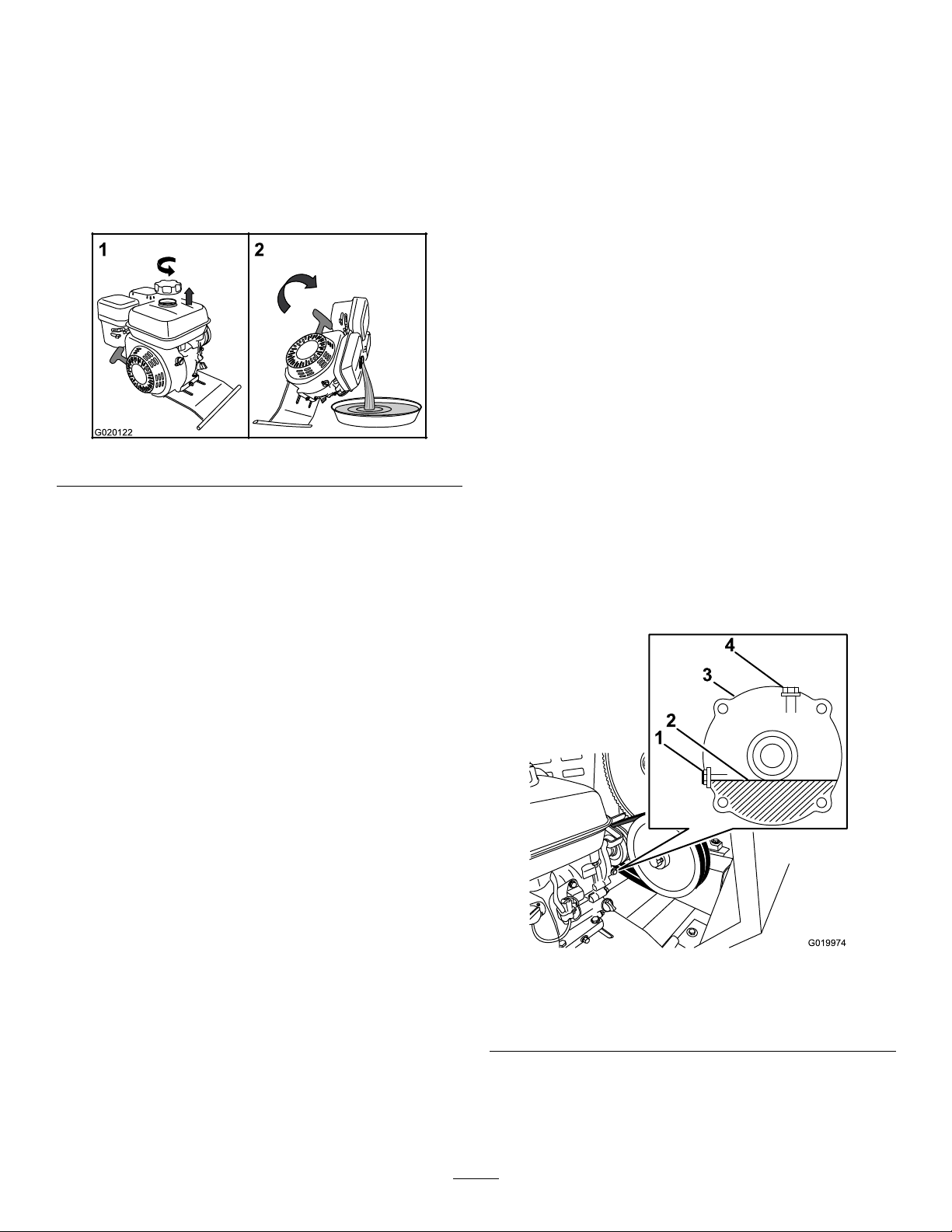
2.Removethefuelcapbyrotatingitcounterclockwise.
Figure64
3.Alignadrainpantothehingeoftheenginedeck.
4.Rotatetheengineonthehingesideoftheenginedeck
anddrainthefuelfromthetank.
5.Carefullylowertheengineandenginedeck.
6.Installthefuelcap.
ServicingtheReduction Case—Belt-driveModels
Models68013Cand68014Conly
Important:Use4-cyclemotoroilthatmeetsorexceeds
therequirementsforAPIservicecategory
equivalent).
Important:Iftheoillevelinthereductioncaseistoo
lowortoohighandyouruntheengine,youmaydamage
theengineorthereductioncase.Thistypeofdamageis
notcoveredbythewarranty.
Oiltype:SAE10W-30motoroil
Reductioncasecapacity:1.2L(40oz)
CheckingtheReduction-CaseOil
ServiceInterval:Beforeeachuseordaily—Checkthe
reduction-caseoil(Models68013Cand
68014Conly).
1.Removethedividerplate;refertoRemovingthe
DividerPlate(page28).
2.Locatethereductioncasebetweentheengineandthe
enginepulley(Figure65).
SJ or later
(or
7.Installtheengine;refertoInstallingtheEngine(page
35).
1.Oil-level-checkboltand
washer
2.Oillevel(normal)
3.Alignaragbelowtheoil-levelportinthesideofthe
reductioncase.
4.Removetheoil-level-checkboltandwasherfromthe
oil-levelport(Figure65).
Figure65
3.Reductioncase
4.Fillerboltandwasher
36
Page 37
•Iftheoillevelisbelowthethreadsintheoil-level
4
G020127
1
2
3
5
2
6
G020128
port,addoilasfollows:
A.Removethellerboltandwasherfromthe
llerportonthetopofthereductioncase
(Figure65).
B.Slowlyaddthespeciedoilintothellport
untiltheoillevelislevelwiththethreadsat
thebottomoftheoil-levelport.
C.Installthellerboltandthewashertothe
llerportofthereductioncase,andtighten
thellerbolt(
Figure65).
•Iftheoillevelistoohigh,allowtheoiltoowout
untilitisushwiththethreadsatthebottomof
theoil-levelport.
5.Whentheoilislevelisushwiththethreadsatthe
bottomoftheoil-levelport,installtheoil-level-check
boltandthewashertotheportandtightenthe
oil-level-checkbolt(Figure65).
6.Installthedividerplate;refertoInstallingtheDivider
Plate(page28).
ChangingtheReduction-CaseOil
ServiceInterval:Aftertherst20hours—Changethe
reduction-caseoil(Models68013Cand
68014Conly).
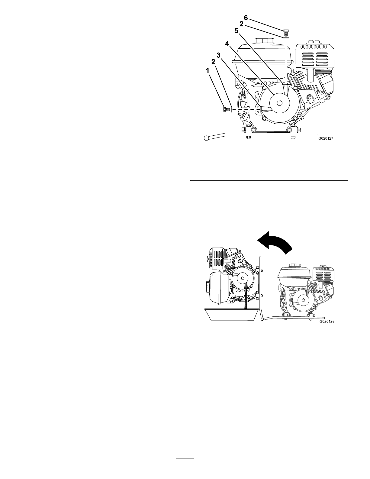
Figure66
1.Oil-level-check
bolt
2.Washer4.Pulley6.Fillerbolt
3.Oil-levelport
5.Fillerport
4.Removetheoil-level-checkboltandwasherfromthe
oil-levelportinthesideofthereductioncase(Figure
66).
5.Alignadrainpantothehingeoftheenginedeck
(Figure67).
Every100hours/Every6months(whichevercomes
rst)—Changethereduction-caseoil(Models68013C
and68014Conly).
1.Removetheengine;refertoRemovingtheEngine
(page34).
2.Drainthefueltank;refertoDrainingtheFuelTank
(page36)
.
3.Removethellerboltandwasherfromthellerport
onthetopofthereductioncase(Figure66).
Figure67
6.Rotatetheengineonthehingesideoftheenginedeck,
anddraintheoilfromthereductioncase(Figure67).
7.Carefullylowertheengineandenginedeck.
8.Slowlyaddthespeciedoilintothellportuntilthe
oillevelislevelwiththethreadsatthebottomofthe
oil-levelport(
Figure65).
9.Installtheoil-level-checkboltandwashertothe
oil-levelportofthereductioncase,andtightenthe
oil-level-checkbolt(Figure66).
10.Installthellerboltandwashertothellerportofthe
reductioncase,andtightenthellerbolt(
37
Figure66).
Page 38
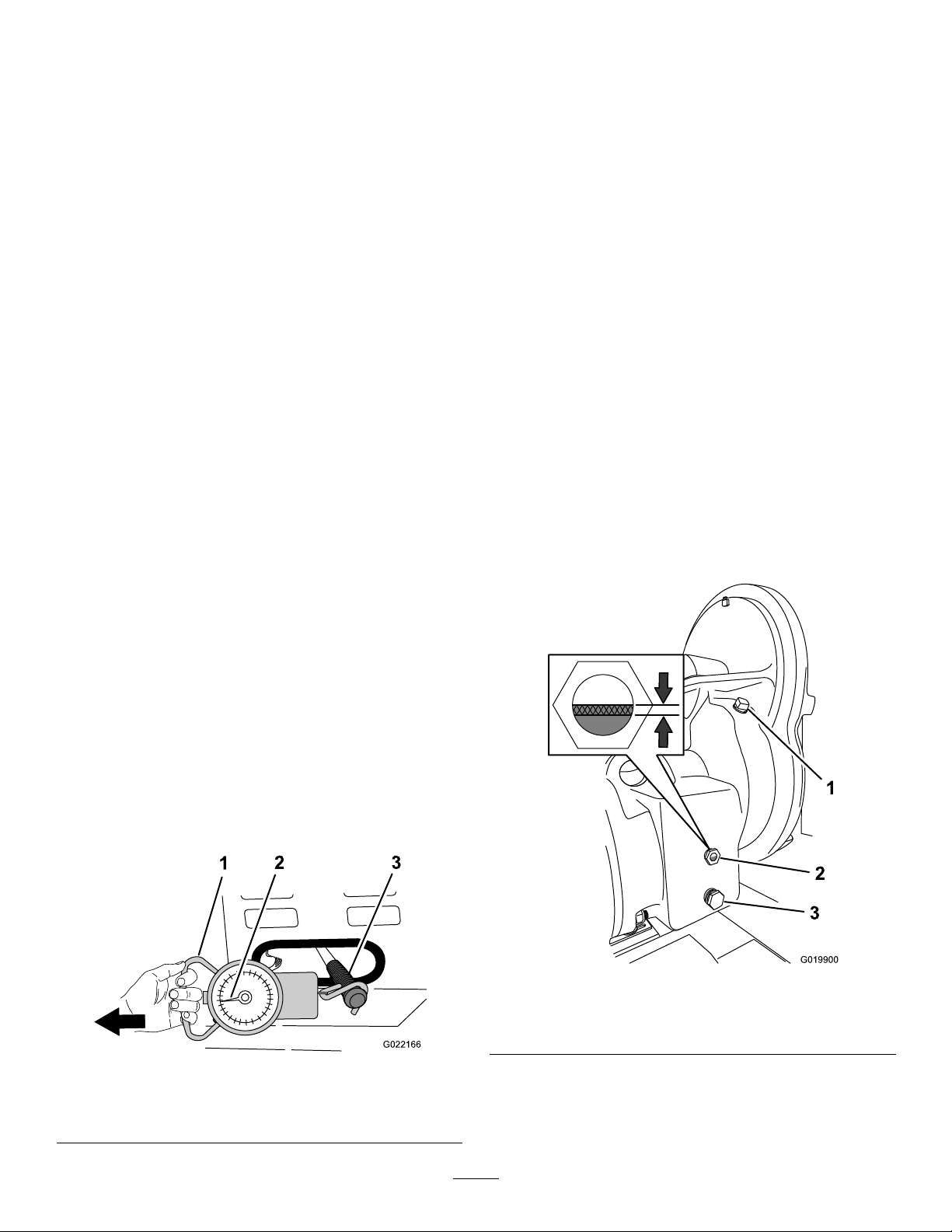
11.Installtheengine;refertoInstallingtheEngine(page
G022166
1
2
3
G019900
1
2
3
35).
ServicingtheGear Case—Gear-CaseModel
Model68024Conly
CheckingtheClutchOperation
ServiceInterval:Beforeeachuseordaily—Checktheclutch
operation(Model68024Conly).
1.MovetheclutchlevertotheOffposition;referto
ControllingthePaddles(page22).
2.Starttheengine;referto
3.Ensurethattheenginethrottleissettothe2/3
position.
4.IfthepaddlesrotatewiththeclutchlevertotheOff
positiondothefollowing:
A.Stoptheengine;referto
(page22).
B.Checktheclutchleverforce;refertoChecking
theClutchLever(page38).
CheckingtheClutchLever
ServiceInterval:Aftertherst25hours—Checkthe
gear-caseclutch(Model68024Conly).
StartingtheEngine(page21).
StoppingtheEngine
5.Usingthespringscale,pulltheclutchhandletotheOn
positionasshowninFigure68.
6.Observethespringscalewhilepullingtoseewhatthe
highestpressureiswhenmovingtheclutchhandle
fromtheOffpositiontotheOnposition(Figure68).
Note:Normalclutchpressureis15to30kg(35to
55lb).
7.Iftheclutchpressureisgreaterthanorlessthan
15to30kg(35to55lb),contactanAuthorizedToro
ServiceDealer.
CheckingtheGear-caseOil
ServiceInterval:Every40hours—Checkthegear-caseoil
(Model68024Conly).
Important:Iftheoillevelinthegearcaseistoolow
ortoohighandyouruntheengine,youmaydamage
theengineorthegearcase.Thistypeofdamageisnot
coveredbythewarranty.
OilType:SAE90gearoil
Gear-caseCapacity:2.13L(72oz)
1.Locatethegearcasebetweentheengineandthefront
cowl.
2.Attherightsideofthegearcase,examinetheoillevel
inthesightglass(Figure69).
Important:Checkthegearcaseclutchifthepaddles
rotatewhentheclutchleverisintheOffposition,ifthe
paddlesrotateslowly,oriftheclutchbeginstoslip.
1.EnsurethattheengineisOff;referto
Engine(page22).
2.Locatetheclutchleveratthebackofthemachine;refer
toClutchLever(page11).
3.MovetheclutchlevertotheOffposition;referto
ControllingthePaddles(page22).
4.Attachaspringscalewitharangeof15to30kg(35to
55lb)tothegripoftheclutchlever(Figure68).
1.Springscale3.Clutchlever
2.15to30kg(35to55lb)
Figure68
Stoppingthe
Figure69
1.Fillplug3.Drainplug
2.Sightglass
3.Iftheoillevelisbelowthebottom1/3ofthesight
glass,addoilasfollows:
A.Removethellplugfromthellportinthe
housingofthegearcase(Figure69).
38
Page 39

B.Slowlyaddthespeciedoilintothellportuntil
theoillevelisbetween1/3and1/2ofthesight
glass(Figure69).
BeltMaintenance
C.Cleanthellplug.
D.ApplyPTFEthread-sealingtapetothethreads
oftheplug.
E.Installtheplugintothellportinthehousing
Figure69).
(
ReplacingtheGear-caseOil
ServiceInterval:Every800hours—Replacethegear-case
oil(Model68024Conly).
1.Alignadrainpanwitha3-quartcapacityunderthe
drainplug(Figure69).
2.Removethedrainplugfromthedrainport,and
completelydrainthegear-caseoil(Figure69).
3.Removethellplug(Figure69).
4.Cleanthedrainandllplugs,andapplyPTFE
thread-sealingtapetotheplugthreads.
5.Installthedrainpluginthedrainport(Figure69).
6.Slowlyaddthespeciedoilintothellportuntilthe
oillevelisbetween1/3and1/2ofthesightglass
(Figure69).
7.Installthellpluginthellport(
Figure69).
ServicingtheBelts—Belt-drive Models
Models68013C,68014C,68016C,68017C,68020C,and
68021Conly
InspectingtheBelts
ServiceInterval:Aftertherst25hours—Inspectthebelts
andadjustasnecessary.
Every40hours—Inspectthebeltsandadjustas
necessary.
1.Removethedividerplate;referto
DividerPlate(page28).
2.MovetheclutchlevertotheOffposition;referto
ControllingthePaddles(page22).
3.Examinethebeltsforwearordamage.Ifthebeltsare
wornordamaged,replacethem;refertoReplacingthe
Belts—Belt-driveModels(page40).
4.Examinethepulleysforwear,damage,and
misalignment;refertoAligningthePulleys—Belt-drive
Models(page42).
5.Installthedividerplate;refertoInstallingtheDivider
Plate(page28).
Removingthe
AdjustingtheBeltTension
Clutchairgap:6.35to9.52mm(1/4to3/8inch)
1.MovetheclutchlevertotheOnposition;referto
ControllingthePaddles(page22).
2.Measuretheairgapbetweentheenginedeckandthe
rollerontheclutch(Figure70).
39
Page 40
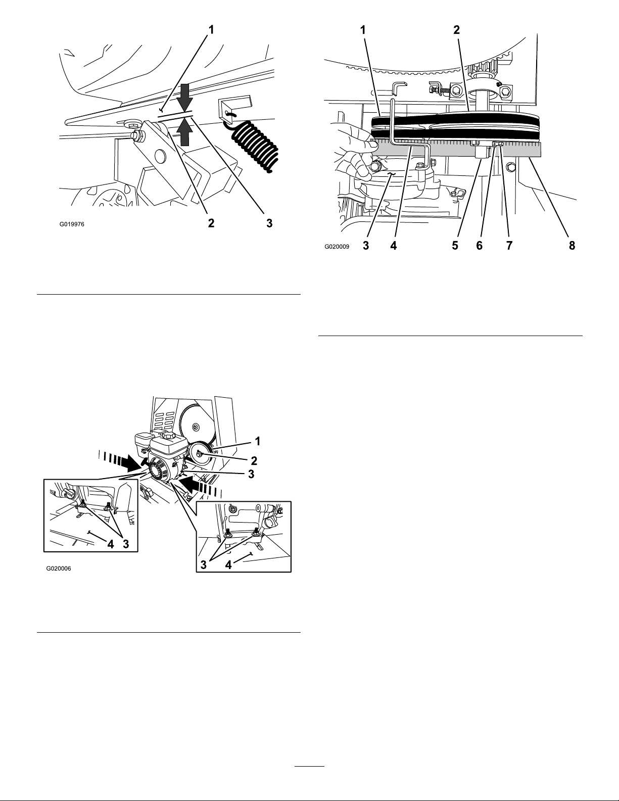
G019976
1
2
3
Figure70
4
3
4
3
1
2
3
G020006
G020009
1 2
3
4
5
6 7 8
1.Enginedeck
2.Clutchroller
3.Clutchairgap:6.35to
9.52mm(1/4to3/8inch)
3.Ifthemeasuredairgapisnotwithinthespecied
range,adjustthegapasfollows:
A.MovetheclutchlevertotheOffposition;referto
ControllingthePaddles(page22).
B.Loosenthenutsandboltsthatsecuretheengine
totheenginedeck(Figure71).
Figure72
1.Enginepulley
2.Idlerpulley6.Jamnut
3.Reductioncase(engine)7.Setscrew
4.Beltguide
5.Idlershaft
8.Straightedge
E.Ifneeded,pivottheengineontheenginedeck
untiltheenginepulleyandtheidlerpulleyare
alignedtothestraightedge(Figure72).
F.Tightenthenutsandboltsthatsecuretheengine
totheenginedecktoatorqueof18N-m(13
ft-lb).
G.Checktheairgapbetweentheenginedeckand
therollerontheclutch.Iftheairgapisnotwithin
thespeciedrange,repeatstep3untiltheairgap
measurementiswithinthespeciedrange.
H.Installthedividerplate;refertoInstallingthe
DividerPlate(page28).
Replacingthe
1.Idlerpulley3.Nutandbolt
2.Setscrew
Figure71
4.Enginedeck
C.Movetheenginepositionasfollows:
•Increasetheairgap—movetheengine
awayfromtheidlerpulley(
•Decreasetheairgap—movetheengine
towardtheidlerpulley(Figure71).
D.Alignastraightedgeacrosstheenginepulleyand
theidlerpulley(Figure72).
Figure71).
Belts—Belt-driveModels
ServiceInterval:Every2years—Replacethebelts.
Models68013C,68014C,68016C,68017C,68020C,and
68021Conly
RemovingtheBelts
1.MovetheclutchlevertotheOffposition;referto
ControllingthePaddles(page22).
2.Removethedividerplate;referto
DividerPlate(page28).
3.Removetheboltthatsecuresthebeltguidetothe
engine,andremovethebeltguide(Figure73).
40
Removingthe
Page 41
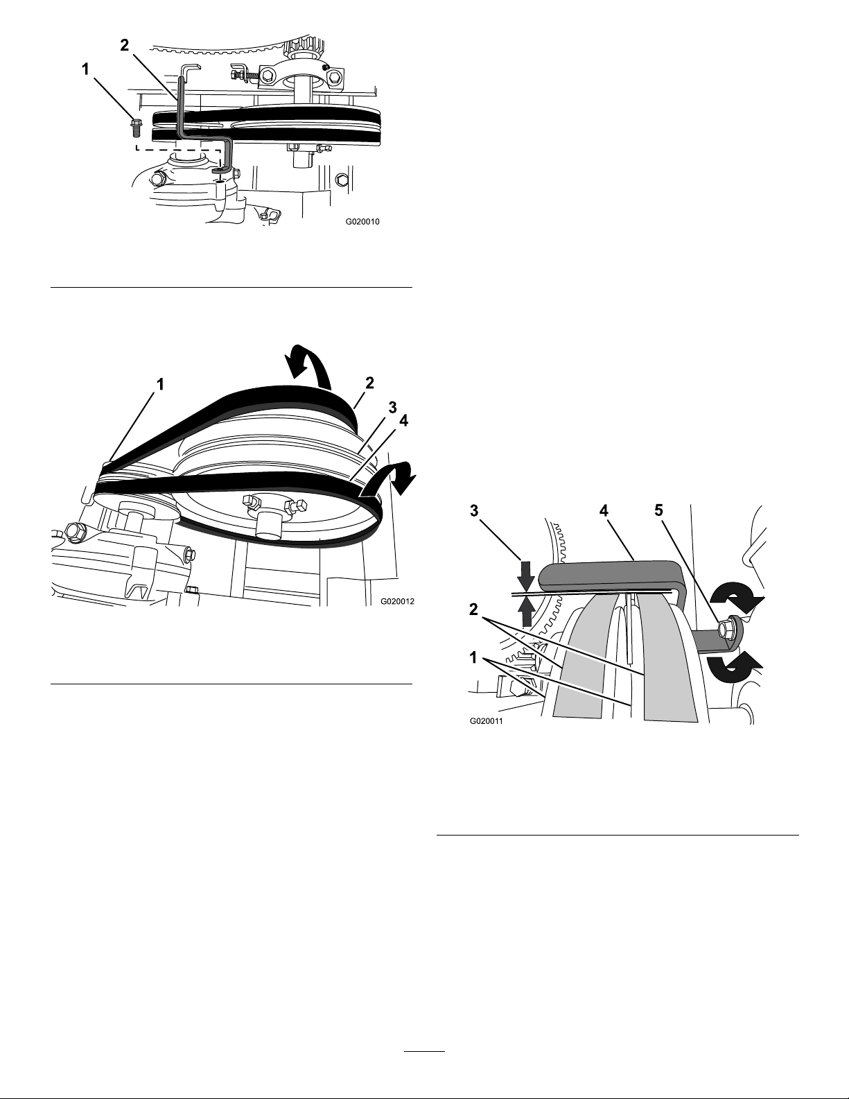
2
G020010
Figure73
2
3
4
1
G020012
G02001 1
3 4
5
1
2
1.Bolt2.Beltguide
5.Sliptheforwardbeltovertheenginepulleyandalign
thebelttotheforwardpulleygroove.
6.Checkthebelttension;refertostep
1,step2,andstep
3inAdjustingtheBeltTension(page39).
7.Looselysecurethebeltguidetotheengine(Figure73)
withtheboltthatwasremovedinstep3ofRemoving
theBelts(page40).
8.Adjustthebeltguide;refertoAdjustingtheBeltGuide
(page41).
9.Installthedividerplate;refertoInstallingtheDivider
Plate(page28).
AdjustingtheBeltGuide
4.Sliptheforwardbeltforwardandofftheidlerpulley
(Figure74).
Figure74
1.Enginepulley3.Idlerpulley
2.Forwardbelt4.Rearbelt
5.Sliptherearbeltrearwardandofftheidlerpulley
(Figure74).
6.Slipthebeltsofftheenginepulley .
7.Removethebeltsfromthemachine.
InstallingtheBelts
Note:Toaccessthebeltguide,removethedividerplate;
refertoRemovingtheDividerPlate(page28).
Guideairgap:2.5to4.0mm(3/32to5/32inch)
1.EnsurethattheclutchleverisintheOnposition;refer
to
ControllingthePaddles(page22).
2.Ensurethatthebelttensioniscorrect;referto
AdjustingtheBeltTension(page39).
3.Checkthattheairgapbetweenthebeltguideandthe
beltsis2.5to4.0mm(3/32to5/32inch);referto
Figure75.
Figure75
1.Enginepulleys4.Beltguide
2.Belts5.Bolt
3.Guideairgap:2.5to4.0
mm(3/32to5/32inch)
1.EnsurethattheclutchleverisintheOffposition;refer
toControllingthePaddles(page22).
2.Aligntherearbelttothereargrooveintheengine
pulley.
Note:Donotaligntherearbelttotheidlerpulley.
3.Aligntheforwardbelttotheforwardgrooveofthe
idlerpulley.
4.Sliptherearbeltovertheidlerpulleyandalignthebelt
totherearpulleygroove.
4.Iftheairgapisnotwithinthespeciedrange,dothe
following:
A.Loosentheboltthatsecuresthebeltguidetothe
engine(
Figure75).
Important:Ensurethatthebeltguideis
towardtheenginepulley.
B.Rotatethebeltguideupordownuntilthereis
anairgapof2.5to4.0mm(3/32to5/32inch)
betweentheguideandeachbelt(
41
Figure75).
Page 42
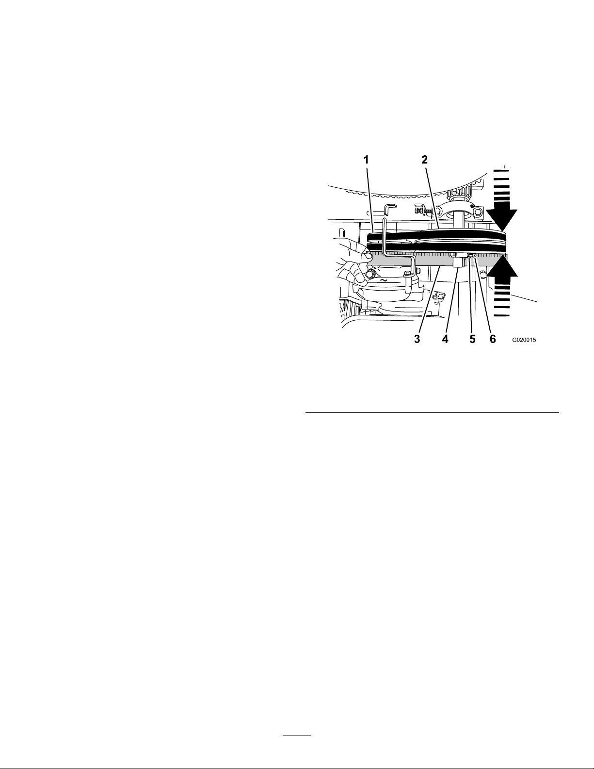
Important:Thebeltguideshouldnot
G020015
53 6
1 2
4
contactthebeltswiththeclutchleverinthe
Onposition.
Aligningthe Pulleys—Belt-driveModels
Note:Iftheairgapbetweenthebeltguideand
bothbeltscannotbeattained,thenoneofthe
beltsistoolong.
C.Tightentheboltthatsecuresthebeltguidetothe
engine(Figure75).
D.Checktheclutchoperation;refertoCheckingthe
ClutchOperation(page42).
5.Installthedividerplate;refertoInstallingtheDivider
Plate(page28).
CheckingtheClutchOperation
ServiceInterval:Every40hours—Checktheclutch
operation(Models68013C,68014C,
68016C,68017C,68020C,and68021C
only).
Important:Thepaddlesmustnotrotateinanempty
drumwhentheclutchleverisintheOffposition.
1.MovetheclutchlevertotheOffposition;referto
ClutchLever(page11).
2.Starttheengine;refertoStartingtheEngine(page21).
3.IfthepaddlesrotatewiththeclutchlevertotheOff
positiondothefollowing:
A.Stoptheengine;refertoStoppingtheEngine
(page22).
Models68013C,68014C,68016C,68017C,68020C,and
68021Conly
1.Removethedividerplate;referto
DividerPlate(page28).
2.Placeastraightedgeacrossthefaceoftheenginepulley
andtheidlerpulley(Figure76).
Figure76
1.Enginepulley
2.Idlerpulley5.Locknut
3.Straightedge6.Setscrew
4.Idlershaft
Removingthe
B.Checktheairgapbetweenthebeltguideandthe
belts.
Note:Iftheairgapislargerthan4.0mm(0.16
inch),decreasethegapbetweenthebeltguide
andthebelts;refertoAdjustingtheBeltGuide
(page41).
4.Repeatsteps1,2,and3untilallthefollowing
conditionsaremet:
•Theengineisrunat2/3throttle.
•TheclutchleverisintheOffposition.
•Thepaddlesdonotrotateinanemptydrum.
Note:Bothpulleysmustbealignedushwiththe
straightedge.
3.Ifthepulleysarenotaligneddothefollowing:
A.MovetheclutchlevertotheOffposition.
B.Loosenthelocknutsandsetscrewsthatsecurethe
idlerpulleytotheidlershaft(Figure76).
C.Usingasoft-facemallet,taptheidlerpulley
forwardorbackwardalongtheidlershaftuntil
theenginepulleyandtheidlerpulleyarealigned
tothestraightedge(Figure76).
D.Tightenthesetscrewsandlocknutsthatsecurethe
idlerpulleytotheidlershaft(Figure76).
4.Installthedividerplate;refertoInstallingtheDivider
Plate(page28).
42
Page 43
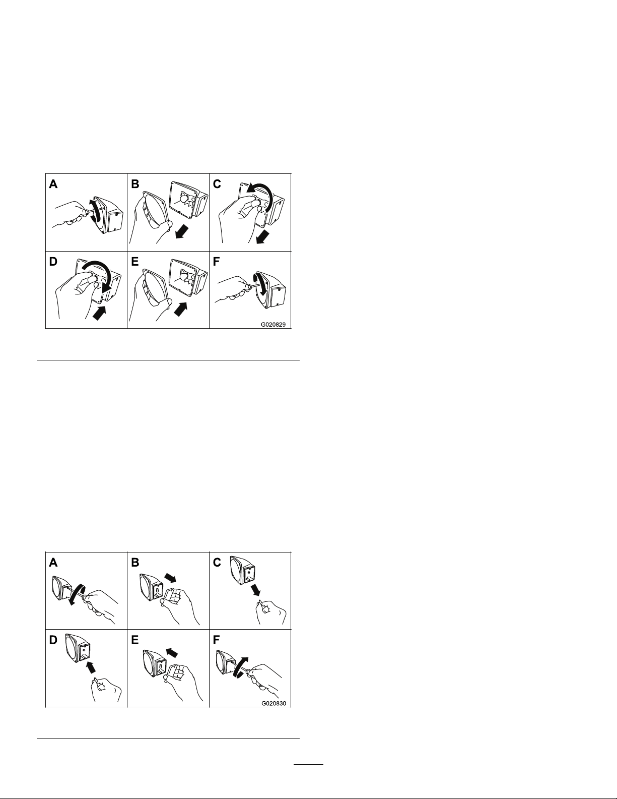
ReplacingtheLight
A
B
C
E
F
G020829
A
B
C
E
F
G020830
Bulbs
2.Removethelens(Figure78).
3.Pullthebulboutofthesocket(Figure78).
4.Pushanew168bulbintothesocket(Figure78).
ReplacingtheRear-facing Bulbs
Note:Theleftrear-facingbulbalsoilluminateslicenseplate.
1.Useascrewdrivertoremovethe4screwsfromthe
largesquarelensonthelight(Figure77).
Figure77
2.Removethelens(Figure77).
3.Pushandtwistthebulbcounterclockwisetoremoveit
fromthesocket(
4.Pushanew1157bulbintothesocketandthentwistit
clockwise(Figure77).
5.Installthelensandthe4screws(Figure77).
Figure77).
5.Installthelensandthe2screws(
Figure78).
ReplacingtheSide-facing Bulbs
1.Useascrewdrivertoremovethe2screwsfromthe
smallrectangularlensonthesideofthelight(Figure
78).
Figure78
43
Page 44

Cleaning
Storage
CleaningtheMachine
Regularcleaningandwashingwillincreasethelifespanof
themachine.Cleanthemachineaftereachuse,beforethe
dirthardens.
Ensurethatthefueltankcapandoilcap/dipstickaresecure
toavoidgettingwaterinthetank.
Usecarewhenusingahigh-pressuresprayerbecauseitcan
damagewarningdecals,instructionsigns,andtheengine.
Important:Lubricatethetrunnionsaftercleaning;refer
toLubricatingtheBearingsandSeals(page29).
StoringtheMachine
Forstorageover30days,preparethemachineasfollows:
1.Removedirtandgrimefromtheexternalpartsofthe
entiremachine,especiallytheengine.Cleandirtand
debrisfromtheoutsideoftheenginecylinder-head
nsandblowerhousing.
Important:Y oucanwashthemachinewithmild
detergentandwater.
2.Conditionthefuelsystemasfollows:
A.Addapetroleum-basedstabilizer/conditionerto
fuelinthetank.Followthemixinginstructions
fromthestabilizermanufacturer.Donotusean
alcohol-basedstabilizer(ethanolormethanol).
Important:Donotstore
stabilizer/conditionedfuelover90days.
Note:Fuelstabilizer/conditionerismost
effectivewhenmixedwithfreshfuelandusedat
alltimes.
B.Runtheenginefor5minutestodistributethe
conditionedfuelthroughthefuelsystem.
C.Stoptheengine,allowittocool,anddrainthe
fueltankusingapump-typesiphon.Disposeof
fuelproperly;recycleitaccordingtolocalcodes.
D.Starttheengineandrunituntilitstops.
E.Choketheengine.
F.Startandruntheengineuntilitwillnotstartagain.
3.Cleanthesedimentcup;referto
Cup(page35)
4.Servicetheaircleaner;refertoServicingtheAir
Cleaner(page30).
5.Changetheenginecrankcaseoil;refertoChangingthe
EngineOil(page30).
6.Removethesparkplugandcheckthecondition;refer
toRemovingtheSparkPlug(page32).
7.Conditiontheengineasfollows:
A.Removethesparkplugandpour2tablespoons
ofengineoilintothespark-plughole;referto
RemovingtheSparkPlug(page32).
B.Pulltherecoil-starthandleslowlytocrankthe
engineanddistributetheoilinsidethecylinder.
C.Installthesparkplug;referto
Plug(page32).
.
CleaningtheSediment
ServicingtheSpark
Note:Donotinstallthewireonthesparkplug.
8.Greasethemachine;refertoLubricatingtheBearings
andSeals(page29).
9.Checkandtightenallbolts,nuts,andscrews.Repairor
replaceanypartthatisdamaged.
44
Page 45

10.Paintallscratchedorbaremetalsurfaces.Paintis
availablefromyourAuthorizedToroDealer.
11.Storethemachineinaclean,drygarageorstoragearea.
12.Coverthemachinetoprotectitandkeepitclean.
45
Page 46

Troubleshooting
Problem
Theenginewillnotstart.
Theenginelackspowerorrunsrough.
PossibleCauseCorrectiveAction
1.Thefuel-valveleverisintheOff
position.
2.Thechokeisclosed
3.Thechokeisopen.
4.TheengineOn/OffswitchisintheOff
position.
5.Theengineoillevelislow(engines
withtheoil-levelswitch).
6.Thefueltankisempty.6.Fillthefueltankwithfreshfuel.
7.Theenginecontainsbad/oldfuel.7.Drainthefueltankandcarburetor.
8.Thesparkplugisfouledorimproperly
gapped.
9.Thesparkplugiswetwithfuel(ooded
engine).
10.Thespark-plugwireislooseor
disconnected.
1.Theairlterisrestricted.1.Cleanorreplacetheairlterelement(s).
2.Theenginecontainsbad/oldfuel.2.Drainthefueltankandcarburetor.
3.Thereiswaterorcontaminationinthe
fuel.
4.Thefuellineisrestricted.4.Cleanthefuellterandsedimentcup.
5.Thechokeisclosed
6.Thesparkplugiswornorhasbuildup
ontheelectrodes.
7.Thereistoomuchoilintheengine
crankcase.
1.Movethefuel-valvelevertotheOn
position.
2.Openthechokewhenstartingahot
engine.
3.Closethechokewhenstartingacold
engine.
4.RotatetheswitchtotheOnposition.
5.Filltheengine,withtherecommended
oil,totheproperlevel.
Refuelwithfreshgasoline.
8.Gaporreplacethesparkplug.
9.Removethesparkplug,dryit,and
installtheplug.Starttheenginewith
thethrottleintheMaxposition.
10.Removethespark-plugwire,cleanthe
spark-plugterminalandtheterminal
socketinthebootofthespark-plug
wire,andreinstallthespark-plugwire.
Refuelwithfreshgasoline.
3.Drainthefueltankandcarburetor.
Refuelwithfreshgasoline.
5.Openthechoke.
6.Checktheelectrodegapandadjustor
replacethesparkplug.
7.Draintheoiltotheproperlevel.
Thebeltssliporcomeoffthepulleys
(Models68013C,68014C,68016C,
68017C,68020C,and68021C).
isintheOffposition(Models68013C,
68014C,68016C,68017C,68020C,and
68021C).
Thepaddlesrotatewhentheclutchlever
isintheOffposition(Model68024C).
leverisintheOnposition(Models68013C,
68014C,68016C,68017C,68020C,and
68021C).
Thepaddlesdonotrotatewhentheclutch
leverisintheOnposition(Model68024C).
1.Thebelttensionisinsufcient.
2.Thebeltsareworn.2.Replacethebelts.
3.Thepulley(s)areworn.3.ContactyourAuthorizedService
4.Thepulley(s)aremisaligned.4.Alignthepulley(s).
1.Theclutchleverisnotadjusted
correctly.
2.Thebeltguideisnotadjustedcorrectly.2.Adjustthebeltguide.
1.Theclutchisnotadjustedcorrectly.
1.Theclutchleverisnotadjusted
correctly.
2.Thepaddlesarestuckinthedrum
1.Theclutchisnotadjustedcorrectly.
1.Adjustthebelttension.
Dealer.
1.Adjustthebelttension. Thepaddlesrotatewhentheclutchlever
1.ContactyourAuthorizedService
Dealer.
1.Adjustthebelttension. Thepaddlesdonotrotatewhentheclutch
2.Cleanthepaddlesanddrum.
1.ContactyourAuthorizedService
Dealer.
46
Page 47

Problem
PossibleCauseCorrectiveAction
Thepaddlesrotateslowlywhentheclutch
leverisintheOnposition(Models68013C,
68014C,68016C,68017C,68020C,and
68021C).
Thepaddlesrotateslowlywhentheclutch
leverisintheOnposition(Model68024C).
1.Theclutchleverisnotadjusted
correctly.
1.Theclutchisnotadjustedcorrectly.
1.Adjustthebelttension.
1.ContactyourAuthorizedService
Dealer.
47
Page 48

Alimitedwarranty(seewarrantyperiodsbelow)
TheToroWarranty
Concrete,Masonry,
andCompaction
Equipment
ConditionsandProductsCovered
TheT oroCompanyanditsafliate,T oroWarrantyCompany,pursuantto
anagreementbetweenthem,jointlywarrantyourT oroConcrete,Masonry ,
andCompactionEquipmentProductslistedbelowtobefreefromdefects
inmaterialsorworkmanship.
Thiswarrantycoversthecostofpartsandlabor,butyoumustpay
transportationcosts.
Thefollowingtimeperiodsapplyfromthedateofpurchase:
ProductsWarrantyPeriod
ConcreteMixers
•SpindleBearingsLifetime*(originalowneronly)
MortarMixers1year
•DrumBearingsandSealsLifetime*(originalowneronly)
ForwardPlateCompactors
ReversiblePlates1year
RammerCompactors
MudBuggy1year
VibratingTrenchRoller2years
ConcreteSaws
MasonrySaws
PowerTrowels1year
Screeds
ConcreteVibrators
Whereawarrantableconditionexists,wewillrepairtheProductatnocost
toyouincludingdiagnosis,labor,andparts.
*
LifetimeWarranty-Ifthebearing(s)orseal(s)onyourmixerfail,itwillbereplacedunderwarranty,
atnocostforpartsorlabor.
1year
2years
2years
1year
1year
1year
1year
InstructionsforObtainingWarrantyService
IfyouthinkthatyourT oroProductcontainsadefectinmaterialsor
workmanship,followthisprocedure
1.ContactanyAuthorizedServicingOutlettoarrangeserviceattheir
dealership.Tolocateoneconvenienttoyou,accessourwebsiteat
www.T oro.com.Select“WheretoBuy”andselect“Contractor”under
producttype.Y oumayalsocallourtollfreenumberbelow.
2.Bringtheproductandyourproofofpurchase(salesreceipt)tothem.
3.IfforanyreasonyouaredissatisedwiththeServiceOutlet’s
analysisorwiththeassistanceprovided,contactusat:
SWSCustomerCareDepartment
ToroWarrantyCompany
811 1LyndaleAvenueSouth
Bloomington,MN55420-1 196
TollFree:800-888-9926
**
ToroAuthorizedRentalCustomerswhohavepurchasedproductsdirectlyfromToroandhave
signedtheToroRentalCustomerAgreementhavetheabilitytoperformtheirownwarrantywork.
PleasevisitToro’ sRentalPortalforelectronicwarrantyclamlingproceduresorcallthetollfree
numberabove.
**
:
OwnerResponsibilities
YoumustmaintainyourT oroProductbyfollowingthemaintenance
proceduresdescribedintheOperator’sManual.Suchroutine
maintenance,whetherperformedbyadealerorbyyou,isatyourexpense.
Partsscheduledforreplacementasrequiredmaintenance(“Maintenance
Parts”),arewarrantedfortheperiodoftimeuptothescheduled
replacementtimeforthatpart.Failuretoperformrequiredmaintenance
andadjustmentscanbegroundsfordisallowingawarrantyclaim.
ItemsandConditionsNotCovered
Notallproductfailuresormalfunctionsthatoccurduringthewarranty
periodaredefectsinmaterialsorworkmanship.Thisexpresswarranty
doesnotcoverthefollowing:
•Productfailureswhichresultfromtheuseofnon-Tororeplacement
parts,orfrominstallationanduseofadd-on,modied,orunapproved
accessories
•Productfailureswhichresultfromfailuretoperformrequired
maintenanceand/oradjustments
•ProductfailureswhichresultfromoperatingtheProductinan
abusive,negligentorrecklessmanner
•Partssubjecttoconsumptionthroughuseunlessfoundtobe
defective.Examplesofpartswhichareconsumed,orusedup,during
normalproductoperationinclude,butarenotlimitedto,belts,wipers,
sparkplugs,tires,lters,gaskets,wearplates,seals,O-rings,drive
chains,clutches.
•Failurescausedbyoutsideinuence.Itemsconsideredtobeoutside
inuenceinclude,butarenotlimitedto,weather,storagepractices,
contamination,useofunapprovedcoolants,lubricants,additives,or
chemicals,etc.
•Normal“wearandtear”items.Normal“wearandtear”includes,butis
notlimitedto,wornpaintedsurfaces,scratcheddecals,etc.
•Anycomponentcoveredbyaseparatemanufacturer’swarranty
•Pickupanddeliverycharges
GeneralConditions
RepairbyanAuthorizedServicingOutletorSelf-ServiceasanAuthorized
RentalCustomerisyoursoleremedyunderthewarranty.
NeitherTheToroCompanynorToroWarrantyCompanyisliablefor
indirect,incidentalorconsequentialdamagesinconnectionwith
theuseoftheToroProductscoveredbythiswarranty ,including
anycostorexpenseofprovidingsubstituteequipmentorservice
duringreasonableperiodsofmalfunctionornon-usepending
completionofrepairsunderthiswarranty.Allimpliedwarranties
ofmerchantabilityandtnessforusearelimitedtotheduration
ofthisexpresswarranty.Somestatesdonotallowexclusionsof
incidentalorconsequentialdamages,orlimitationsonhowlong
animpliedwarrantylasts,sotheaboveexclusionsandlimitations
maynotapplytoyou.
Thiswarrantygivesyouspeciclegalrights,andyoumayalsohaveother
rightswhichvaryfromstatetostate.
ExceptfortheenginewarrantycoverageandtheEmissionswarranty
referencedbelow,ifapplicable,thereisnootherexpresswarranty .The
EmissionsControlSystemonyourProductmaybecoveredbyaseparate
warrantymeetingrequirementsestablishedbytheU.S.Environmental
ProtectionAgency(EPA)ortheCaliforniaAirResourcesBoard(CARB).
RefertotheCaliforniaEmissionControlWarrantyStatementsuppliedwith
yourProductorcontainedintheenginemanufacturer’sdocumentationfor
details.
CountriesOtherthantheUnitedStatesorCanada
CustomerswhohavepurchasedT oroproductsoutsidetheUnitedStatesorCanadashouldcontacttheirT oroDistributor(Dealer)toobtainguarantee
policiesforyourcountry,province,orstate.IfforanyreasonyouaredissatisedwithyourDistributor'sserviceorhavedifcultyobtainingguarantee
information,contacttheT oroimporter.Ifallotherremediesfail,youmaycontactusatT oroWarrantyCompany.
AustralianConsumerLaw:AustraliancustomerswillnddetailsrelatingtotheAustralianConsumerLaweitherinsidetheboxoratyourlocalT oro
Dealer.
374-0288RevB
 Loading...