

Page 1

FormNo.3405-112RevB
MM-SeriesMortarMixer
ModelNo.68013—SerialNo.314000001andUp
ModelNo.68014—SerialNo.314000001andUp
ModelNo.68016—SerialNo.314000001andUp
ModelNo.68017—SerialNo.314000001andUp
ModelNo.68020—SerialNo.314000001andUp
ModelNo.68021—SerialNo.314000001andUp
ModelNo.68024—SerialNo.314000001andUp
Registeratwww.T oro.com.
OriginalInstructions(EN)
*3405-112*B
Page 2

ItisaviolationofCaliforniaPublicResourceCode
Section4442or4443touseoroperatetheengineon
anyforest-covered,brush-covered,orgrass-covered
landunlesstheengineisequippedwithaspark
arrester,asdenedinSection4442,maintainedin
effectiveworkingorderortheengineisconstructed,
equipped,andmaintainedforthepreventionofre.
Theenclosedengineowner'smanualissupplied
forinformationregardingtheUSEnvironmental
ProtectionAgency(EPA)andtheCaliforniaEmission
ControlRegulationofemissionsystems,maintenance,
andwarranty.Replacementsmaybeorderedthrough
theenginemanufacturer.
TireInformation—TheDOTtireinformationislocated
onthesideofeachtire.Thisinformationgivesload
andspeedratings.Replacementtiresshouldhavethe
sameorbetterratings;refertoSpecications(page
16)toensurethatthetiresonyourmachinemeetor
exceedtheweightrequirementsofyourmachine.
WARNING
CALIFORNIA
Proposition65Warning
Theengineexhaustfromthisproduct
containschemicalsknowntotheStateof
Californiatocausecancer,birthdefects,
orotherreproductiveharm.
Useofthisproductmaycauseexposure
tochemicalsknowntotheStateof
Californiatocausecancer,birthdefects,
orotherreproductiveharm.
DealerorToroCustomerServiceandhavethemodel
andserialnumbersofyourproductready.Figure1
identiesthelocationofthemodelandserialnumbers
ontheproduct.Writethenumbersinthespace
provided.
Important:Withyourmobiledevice,youcan
scantheQRcodeontheserialnumberdecal(if
equipped)toaccesswarranty,parts,andother
productinformation.
Introduction
Thismachineisdesignedtomixmortar,plaster,
reproongmaterial,grout,andothersmall-grained
Portlandcementproducts.Avehicleequippedwith
anappropriatepintlehitchorballhitchcantowthe
machine.
Readthisinformationcarefullytolearnhowtooperate
andmaintainyourproductproperlyandtoavoid
injuryandproductdamage.Youareresponsiblefor
operatingtheproductproperlyandsafely .
YoumaycontactT orodirectlyatwww.Toro.com
forproductsafetyandoperationtrainingmaterials,
accessoryinformation,helpndingadealer,orto
registeryourproduct.
Wheneveryouneedservice,genuineToroparts,or
additionalinformation,contactanAuthorizedService
©2018—TheToro®Company
8111LyndaleAvenueSouth
Bloomington,MN55420
1.Modelandserialnumberlocation
ModelNo.
SerialNo.
2
g249232
Figure1
Contactusatwww.Toro.com.
PrintedintheUSA
AllRightsReserved
Page 3

Thismanualidentiespotentialhazardsandhas
safetymessagesidentiedbythesafety-alertsymbol
(Figure2),whichsignalsahazardthatmaycause
seriousinjuryordeathifyoudonotfollowthe
recommendedprecautions.
Figure2
Safety-alertsymbol
Thismanualuses2wordstohighlightinformation.
Importantcallsattentiontospecialmechanical
informationandNoteemphasizesgeneralinformation
worthyofspecialattention.
Contents
Safety.......................................................................4
SafeOperatingPractices....................................4
SafetyandInstructionalDecals..........................7
Setup......................................................................10
1InstallingtheDumpHandle............................10
2InstallingtheT owPole....................................11
3InstallingtheSafetyChain..............................12
ProductOverview...................................................13
Controls...........................................................14
EngineControls............................................15
Specications..................................................16
Operation................................................................17
ThinkSafetyFirst..............................................17
TowingtheMachine..........................................17
AdjustingtheAxleWidth...................................20
PreparingtoUsetheMachine...........................21
OpeningtheCowl.............................................21
ClosingtheCowl...............................................22
AddingFuel......................................................22
PerformingDailyMaintenance..........................24
StartingtheEngine...........................................24
ShuttingOfftheEngine.....................................24
MixingtheMaterial...........................................25
DumpingtheMaterial........................................26
CleaningtheDrum............................................26
Maintenance...........................................................27
RecommendedMaintenanceSchedule(s)...........27
Pre-MaintenanceProcedures..............................28
PreparingtheMachineforMaintenance............28
DisconnectingtheSpark-PlugWire..................28
RemovingtheDividerPlate..............................28
InstallingtheDividerPlate................................28
Lubrication..........................................................29
LubricatingtheBearingsandSeals...................29
EngineMaintenance...........................................30
ServicingtheAirCleaner..................................30
ServicingtheEngineOil....................................31
ServicingtheSparkPlug...................................33
CleaningtheSparkArrester..............................34
RemovingandInstallingtheEngine..................35
FuelSystemMaintenance...................................36
CleaningtheFuel-SedimentCup......................36
DrainingtheFuelT ank......................................37
DriveSystemMaintenance..................................37
g000502
TireAirPressure...............................................37
InspectingtheTires..........................................37
TorquingtheWheelLugNuts............................38
ServicingtheReductionCase...........................38
ServicingtheGearbox......................................40
BeltMaintenance................................................42
InspectingtheBelts..........................................42
AdjustingtheBeltT ension.................................42
ReplacingtheBelts...........................................43
AligningthePulleys..........................................45
PaddleMaintenance............................................46
AdjustingthePaddleBlades.............................46
Cleaning..............................................................47
CleaningtheMachine.......................................47
Storage...................................................................48
Troubleshooting......................................................49
3
Page 4

Safety
Improperuseormaintenancebytheoperatoror
ownercanresultininjury.Toreducethepotential
forinjury ,complywiththesesafetyinstructions
andalwayspayattentiontothesafety-alertsymbol
(Figure2),whichmeans:Caution,Warning,or
Danger—personalsafetyinstruction.Failureto
complywiththeinstructionmayresultinpersonal
injuryordeath.
SafeOperatingPractices
Thisproductiscapableofamputatinghands.Always
followallsafetyinstructionstoavoidseriousinjuryor
death.
WARNING
Machiningorhandlingstone,masonry,
concrete,metal,andothermaterialscan
generatedust,mists,andfumescontaining
chemicals,suchassilica,knowntocause
seriousorfatalinjuryorillness,suchas
respiratorydisease,silicosis,cancer,birth
defects,orotherreproductiveharm.
•Controldust,mist,andfumesatthe
sourcewherepossible.Usewaterfordust
suppressionwheneverpossible.
•Usegoodworkpracticesandfollowthe
recommendationsofthemanufactureror
suppliers,OSHA,andotheroccupational
andtradeassociations.
•Alwaysfollowrespiratoryprecautions.
•Whenyoucannoteliminatethehazards
frominhalation,youandallbystanders
shouldweararespiratorapprovedby
OSHAforthematerialthatyouare
handling.
WARNING
Engineexhaustcontainscarbonmonoxide,
whichislethalifinhaled.
Donotruntheengineindoorsorinan
enclosedarea.
•Readandunderstandthecontentsofthis
Operator’sManualbeforeyoustarttheengine.
Ensurethateveryoneusingthisproductknows
howtouseitandunderstandsthewarnings.
•Becomefamiliarwiththesafeoperationofthe
equipment,operatorcontrols,andsafetysigns.
•Alloperatorsandmechanicsshouldbetrained.
Theownerisresponsiblefortrainingthem.
•Neverletchildrenoruntrainedpeopleoperateor
servicetheequipment.Localregulationsmay
restricttheageoftheoperator.
•Theowner/usercanpreventandisresponsible
foraccidentsorinjuriestopeopleordamageto
property.
Towing
•Checkwithyourlocalcountyorstatetowingsafety
regulationsbeforetowingthemachine.
•Toreducethepossibilityofanaccidentwhile
transportingthemachineonpublicroads,ensure
thatthetowingvehicleismechanicallysoundand
ingoodoperatingcondition.
•Shutofftheenginebeforetransportingthe
machine.
•Whentowingwithaballhitch,ensurethatitisthe
propersizeforthehitchcoupleronthemachine.
•Whentowingwithapintlehitch,ensurethatthe
eyeofthetowpoleisthecorrectdimensionfor
thepintlehook.
•Inspectthehitchandcouplingforwear.Donot
towthemachinewithdamagedorwornhitches,
couplings,chains,orothercomponents.
•Checktheairpressureofthetiresonthetowing
vehicleandadjustthepressureasneeded.
•Checkthetiretreadandsidewallfordamageand
wearandreplacethetireifnecessary.
•Properlyattachthesafetychainstothetowing
vehiclebycrossingthechainsandremovingany
extraslack.
•Ensurethatthedirectionalandbrakelightsare
workingproperly(ifequipped).
•Ensurethatthedirectional,backup,andbrake
lightsofthetowvehicleareworkingproperly(if
equipped).
Training
•Parkthemachineonalevelsurface,shutoffthe
engine,waitforallmovingpartstostop,andallow
themachinetocoolbeforeadjusting,cleaning,
storing,orrepairingthemachine.
•Beforetowing,ensurethatyourmachineis
correctlyandsecurelyattachedtothetowing
vehicle.
•Ensurethatthesafetychainsareproperlysecured
tothevehicle,andleaveenoughslackforturning.
4
Page 5

•Donotcarryanymaterialinthemachinewhen
towing.
•Avoidsuddenstopsandstarts.Thiscancause
skiddingorjackkning.Smooth,gradualstartsand
stopsimprovestowing.
•Avoidsharpturnstopreventrolling.T owonlywith
avehiclethathasahitchdesignedfortowing.Do
notattachtowedequipmentexceptatthehitch
point.
•Donottowthemachinefasterthan88km/h(55
mph).
•Usecautionwhenbackingup;useaspotter
outsidethevehicletoguideyou.
•Donotallowanyonetositorrideonthemachine.
•Disconnectthemachinefromthetowvehicle
beforeusingit.
•Placechocksunderneaththetirestopreventthem
fromrollingwhilethemachineisparked.
Preparation
–Ensurethatthelugnutsaretightandtorqued
properly.
–Ensurethatthemachineisproperlysecured.
FuelSafety
•Useextremecareinhandlingfuel.Itisammable
anditsvaporsareexplosive.
•Extinguishallcigarettes,cigars,pipes,andother
sourcesofignition.
•Useonlyanapprovedfuelcontainer.
•Donotremovethefuelcaporllthefueltank
whiletheengineisrunningorhot.
•Donotaddordrainfuelinanenclosedspace.
•Donotstorethemachineorfuelcontainerwhere
thereisanopename,spark,orpilotlight,such
asonawaterheaterorotherappliance.
•Ifyouspillfuel,donotattempttostarttheengine;
avoidcreatinganysourceofignitionuntilthefuel
vaporshavedissipated.
Becomefamiliarwiththesafeoperationofthe
equipment,operatorcontrols,andsafetysigns.
•Useonlyaccessoriesandattachmentsapproved
bythemanufacturer.
•Wearpersonalprotectiveequipmentand
appropriateclothingincluding:
–Hardhat
–Respiratorordustmask
–Faceshield
–Safetyglasses
–Hearingprotection
–Safetyshoes
–Longpants
–Shirtwithlongsleevesthataretightatthe
wrists
–Tight-ttinggloveswithoutdrawstringsorloose
cuffs
•Wearappropriateclothing,includingeye
protection;longpants;substantial,slip-resistant
footwear;andhearingprotection.Tiebacklong
hairanddonotwearloosejewelry .
•Ensurethatthemachineisonalevelsurface
beforeoperatingit.
•Chockthetiresofthemachinetoprevent
unintendedmovement.
•Beforeeveryuse,dothefollowing:
–Inspectthecoupler,ball,andhitch.
–Ensurethatalllightsarefunctioningproperly
(ifequipped).
–Ensurethatthetiresareproperlyinated.
Operation
•Useyourfullattentionwhileoperatingthe
machine.Donotengageinanyactivitythat
causesdistractions;otherwise,injuryorproperty
damagemayoccur.
•Donotrunanengineinanenclosedorpoorly
ventilatedarea.
•Operatethemachineonlyingoodlighting
conditions.
•Beforestartingthemachine,ensurethatthereare
nopeopleorobstaclesnearorunderthemachine.
•Shutofftheenginebeforeleavingthemachinefor
anyreason.
Neverleavearunningmachineunattended.
Alwaysshutofftheengineandverifythatall
movingpartshavestopped.
•Chockthetiresofthemachineorkeepitattached
tothetowingvehiclewhenitisnotinuse.
•Keepyourhandsawayfromanymovingparts.
Keepyourfeetawayfromthetiresandthefront
post.
•Donotoperatethemachineundertheinuence
ofalcoholordrugs.
•Donotplaceyourhandsoranysolidobjectinto
thedrumwhenthemachineisinoperation.
•Donottouchpartsthatmaybehotfromoperation.
Allowthemtocoolbeforeattemptingtomaintain,
adjust,orservicethemachine.
•Nevermovethemachinewhiletheengineis
running.
•Keepthecowlclosedandlatchedduringoperation.
5
Page 6

•Ensurethatalltheguardsandshieldsaresecurely
inplacebeforeoperatingthemachine.
•Ifthemixingpaddlesstrikeanobjectorifthe
machinestartsmakinganunusualnoiseor
vibration,shutofftheengine,waitforallmoving
partstostop,andemptythedrum.Inspectfor
cloggingordamage.Clean,repair,and/orreplace
anydamagedparts.
•Donotchangetheenginegovernorsettingor
overspeedtheengine.
•Donotoperatethemachinewhenthereistherisk
oflightning.
MaintenanceandStorage
•Beforeperformingmaintenance,dothefollowing:
–Parkthemachineonalevelsurface.
–Shutofftheengineandwaitforallmovement
tostopbeforeadjusting,cleaning,orrepairing
themachine.
–Lettheenginecoolbeforeperforming
maintenanceorstoringthemachine.
–Disengageallpowerandoperationcontrols.
•Neverlubricate,service,repair,oradjustthe
machinewiththeenginerunning.
•Keepequipmentmaterialsclearfromthemufer
andenginetopreventres.Cleanupoilorfuel
spills.
•Neverallowuntrainedpersonneltoservicethe
machine.
•Keepyourhands,feet,andclothingawayfrom
movingparts.Ifpossible,donotmakeadjustments
withtheenginerunning.
•Keepallpartsingoodworkingconditionandall
fastenerstightened.Replaceallwornordamaged
decals.
•Removeanybuildupofgrease,oil,ordebrisfrom
themachine.
•Stopandinspectthemachineifanobjectenters
thedrumorcausesanotherobstruction.Makeall
necessaryrepairsbeforestartingthemachine.
•Donottamperwithsafetydevices.
•Chockthetireswhenstoringthemachine.
•Keepallfastenersandhoseclampssecurely
tightenedandallequipmentingoodcondition.
•UseonlygenuineTororeplacementparts.
6
Page 7
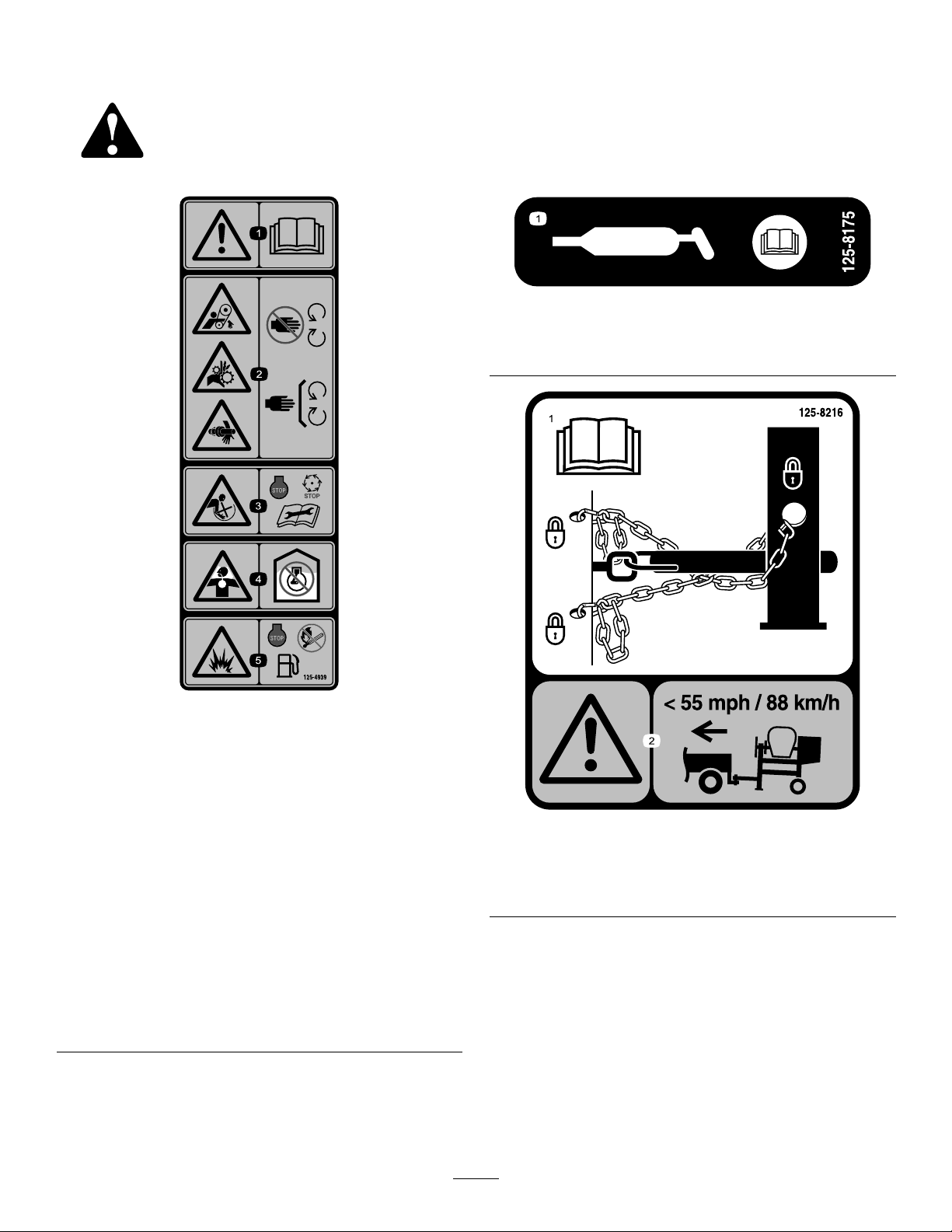
SafetyandInstructionalDecals
Safetydecalsandinstructionsareeasilyvisibletotheoperatorandarelocatednearanyarea
ofpotentialdanger.Replaceanydecalthatisdamagedorlost.
decal125-8175
125-8175
1.ReadtheOperator’sManualforinformationongreasing
themachine.
1.Warning—readthe
Operator’sManual.
2.Handandarm
entanglementatthe
beltdrive;crushinghazard
ofhand;entanglement
hazardofhandatthe
shaft—keepyourhands
awayfrommovingparts;
keepallguardsand
shieldsinplace.
3.Entanglementhazard
atpaddles—shutoff
theengineandwait
forallmovingpartsto
stopbeforeperforming
maintenance.
decal125-4939
125-4939
4.Toxicgasinhalation
hazard—Donotrunthe
engineinanenclosed
space.
5.Explosionhazard—shut
offtheengineandkeep
awayfromameswhen
refueling.
1.ReadtheOperator’s
Manualforinformationon
howtotowthemachine.
125-8216
2.Warning—limittowing
speedtolessthan88km/h
(55mph).
decal125-8216
7
Page 8

decal133-5619
decal130-8322
133-5619
130-8322
1.Usefuelwithanalcohol
contentbyvolumeunder
10%only.
2.ReadtheOperator's
Manualformore
informationonfuel.
3.Donotusefuelwithan
alcoholcontentgreater
than10%byvolume.
1.ReadtheOperator'sManualformoreinformationonservicingthemachine.
decal132-3997
132-3997
8
Page 9

1.ReadtheOperator'sManualformoreinformationonservicingthemachine.
decal132-4043
132-4043
9
Page 10

Setup
LooseParts
Usethechartbelowtoverifythatallpartshavebeenshipped.
ProcedureDescription
Dumphandle1
1
2
3
Bolt2
Nut2
Towpolekit(soldseparately)
Safetychain(includedwiththetowpole
kit)
Connectinglink(includedwiththetow
polekit)
1
InstallingtheDumpHandle
Partsneededforthisprocedure:
1Dumphandle
2Bolt
2Nut
Qty.
Use
Installthedumphandle.
1
1
2
Installthetowpole(side-dumpmodels
only).
Installthesafetychain.
Procedure
1.Cutthecabletiestoremovethedumphandle
fromtheundersideofthegrate.
2.Installthedumphandletothesideofthedrum
using2boltsandnutsasshowninFigure3,
Figure4,orFigure5,asappropriateforyour
model.
g022169
Figure3
Models68013,68016,68020
g022150
Figure4
Models68014,68017,68021
10
Page 11

Figure5
Model68024
g022149
g019804
Figure6
1.Towpole4.Bolthole
2.Frontpost
3.Bolt6.Nut
5.Frametting
2
InstallingtheTowPole
Partsneededforthisprocedure:
1
Towpolekit(soldseparately)
TowPoleSpecications
Purchasethetowpolekit(includingfasteners)that
meetsyourneedsfromyourAuthorizedService
Dealer.Themachinehasthefollowingtowpole
options:
HitchTypeLength
50mm(2inch)ball—stamped78.7cm(31inches)or127cm
50mm(2inch)ball—forged78.7cm(31inches)or127cm
Pintle
(50inches)
(50inches)
78.7cm(31inches)or127cm
(50inches)
2.Slidethetowpoleforwardandaligntheholein
thepolewiththeholeintheframetting(Figure
6).
3.Inserttheboltthroughtheholesinthettingand
thepole(Figure6).
4.Threadthenutontotheboltandtightenthem
untiltheyaretightagainsttheframetting
(Figure6).
Note:Iftheself-lockingnyloninsertinthe
locknutwearswithuse,replacethenutwitha
newGrade5orGrade8locknut.
InstallingtheTowPole
1.Removetheboltandnutfromthetowpole
(Figure6).
11
Page 12
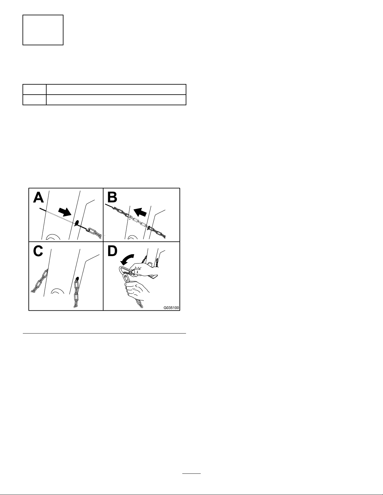
3
InstallingtheSafetyChain
Partsneededforthisprocedure:
1
Safetychain(includedwiththetowpolekit)
2
Connectinglink(includedwiththetowpolekit)
Procedure
Safetychainandconnectinglinkareincludedinthe
towpolekit(soldseparately);referto2Installingthe
TowPole(page1 1).
Formahookontheendofabendablepieceofrodor
stiffwire(notincluded)andinstallthesafetychainand
connectinglinksasshowninFigure7.
Figure7
Note:Ensurethatapproximatelyequallengthsof
safetychainextendfromeithersideofthefrontpost.
g035100
12
Page 13
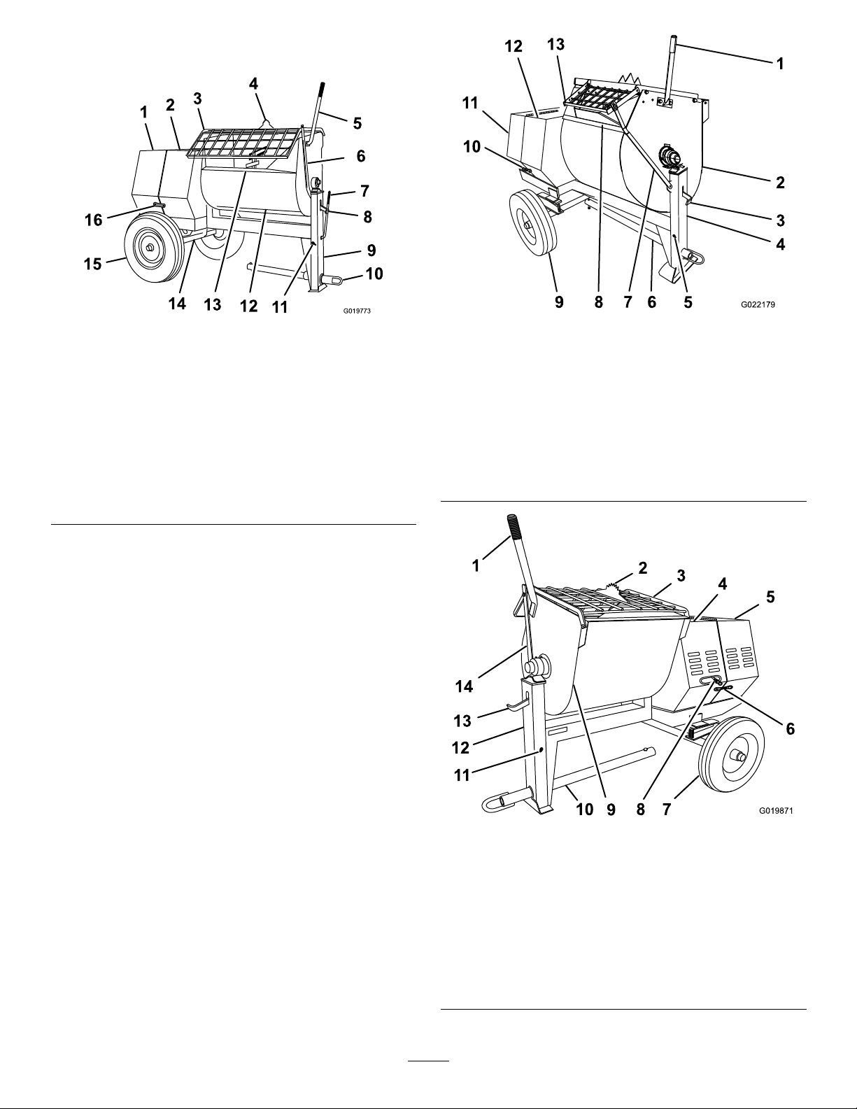
ProductOverview
Figure8
RightSide(Belt-DriveModels)
1.Rearcowl
2.Frontcowl8.Drumlatch14.Axle
3.Grate
4.Bagsplitter10.Towpole
5.Dumphandle
6.Grateliftarm
7.Clutchlever13.Chute
9.Frontpost15.Wheel
11.Safety-chain
keyhole
12.Drum
16.Cowllatch
g019773
Figure9
g022179
RightSide(GearboxModel)
1.Dumphandle6.Towpole11.Rearcowl
2.Drum
3.Drumlatch
assembly
4.Frontpost9.Wheel
5.Safety-chain
keyhole
7.Grateliftarm
8.Chute13.Grate
assembly
10.Cowllatch
12.Frontcowl
1.Dumphandle
2.Bagsplitter7.Wheel
3.Grate8.Clutchlever
4.Frontcowl9.Drum
5.Rearcowl10.T owpole
13
g019871
Figure10
LeftSide(GearboxModel)
6.Cowllatch11.Safety-chain
keyhole
12.Frontpost
assembly
13.Drumlatch
14.Grateliftarm
Page 14
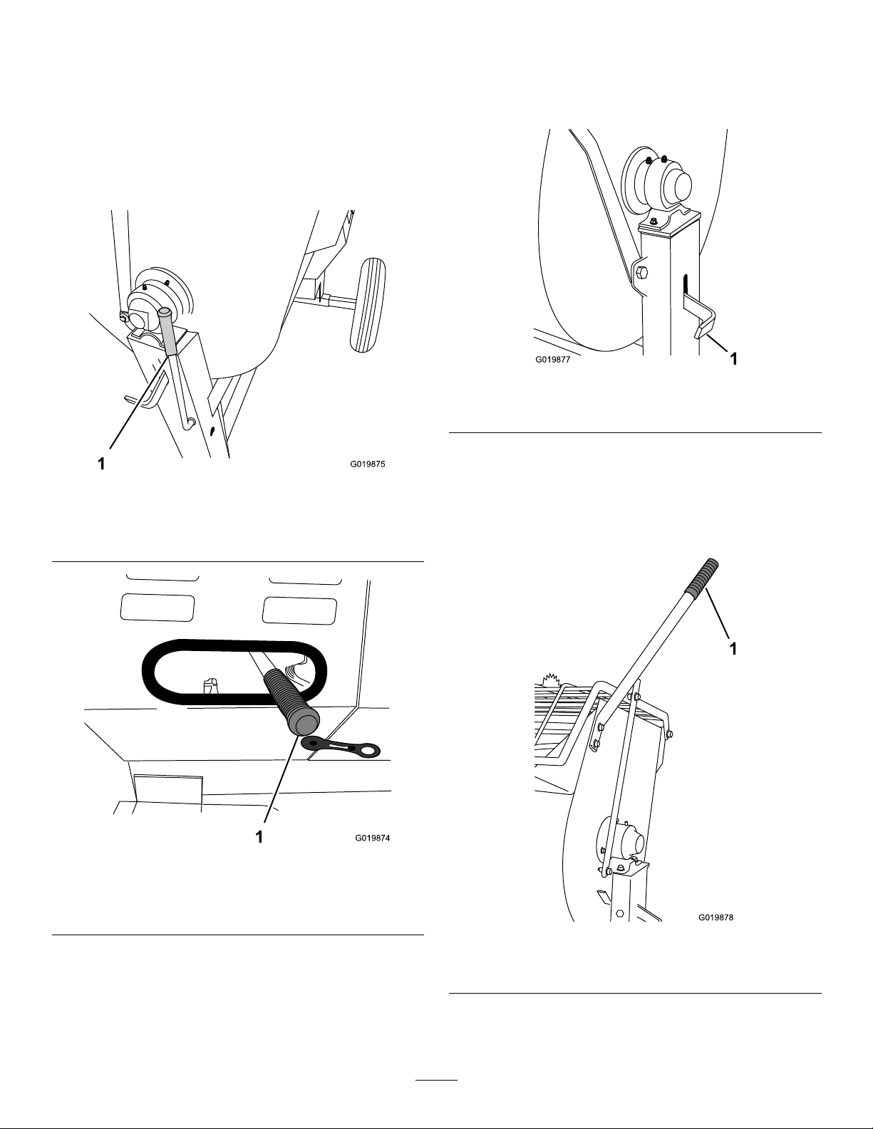
Controls
Becomefamiliarwithallthecontrolsbeforeyoustart
theengineandoperatethemachine.
ClutchLever
Usetheclutchlevertoengageanddisengagethe
paddles.
DrumLatch
Usethedrumlatchtosecurethedrumtothemix
position(upright)formixingoperationsandwhen
transportingthemachine.
g019877
Figure13
1.Drumlatch
1.Clutchlever
Belt-DriveModels
GearboxModel
Figure11
Figure12
g019875
DumpHandle
Usethedumphandletorotatethedrumtothedump
positionandtorotatethedrumtothemixposition
(upright).
g019874
1.Clutchlever
g019878
Figure14
1.Dumphandle
14
Page 15
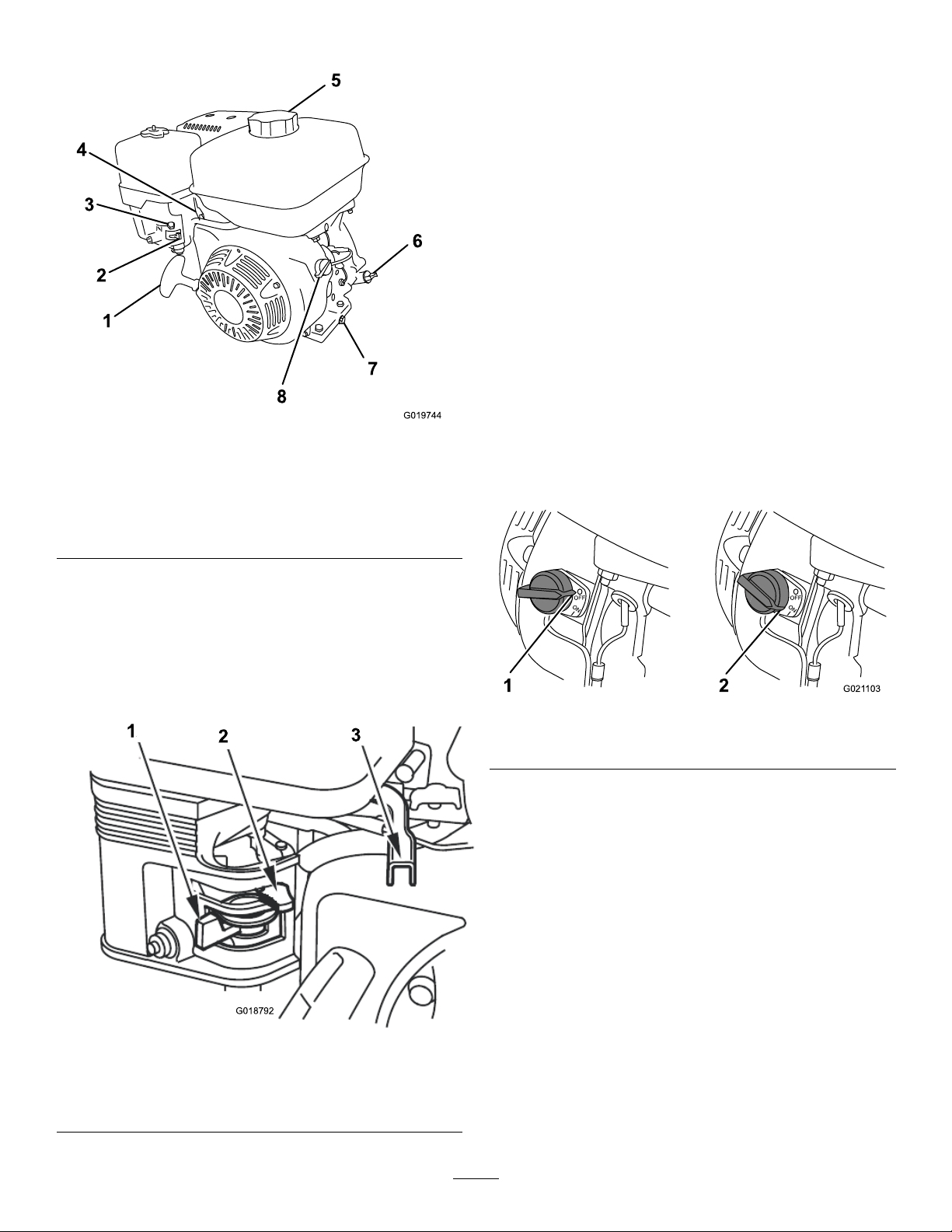
EngineControls
ChokeLever
Usethechokelever(Figure16)tostartacoldengine.
Beforepullingtherecoil-starthandle,movethechoke
levertotheCLOSEDposition.Oncetheengineis
running,movethechokelevertotheOPENposition.
Donotusethechokeiftheengineisalreadywarmed
uporiftheairtemperatureishigh.
ThrottleLever
Thethrottlelever(Figure16)controlsthespeed(rpm)
oftheengine.Itislocatednexttothechokelever.It
setstheenginespeedandthereforecanincreaseand
decreasetherotationspeedofthemixingpaddles.
Forbestperformance,setthiscontroltotheFAST
positionwhenmixingmaterial.
EngineOn/OffSwitch
Figure15
1.Recoil-starthandle5.Fuelcap
2.Fuelvalve
3.Chokelever
4.Throttlelever
FuelValve
6.Oildipstick
7.Oil-drainplug
8.On/Offswitch
Thefuelvalve(Figure16)islocatedunderneaththe
chokelever.Movetheleverforthefuelvalvetothe
ONpositionbeforeattemptingtostarttheengine.
Whenyouhavenishedmixing,shutofftheengine
andmovethefuel-valvelevertotheOFFposition.
g019744
TheOn/Offswitchislocatedonthefrontoftheengine.
•RotateittotheONpositiontostartandrunthe
engine.
•RotateittotheOFFpositiontoshutofftheengine.
g021103
Figure17
1.OFFposition2.ONposition
Recoil-StartHandle
Tostarttheengine,pulltherecoil-starthandle(Figure
15)quicklytoturntheengineover.Theengine
controlsdescribedabovemustallbesetcorrectlyfor
theenginetostart.
Figure16
1.Fuelvalve3.Throttlelever
2.Chokelever
Oil-LevelSwitch
Theoil-levelswitchislocatedinsidetheengine,andit
doesnotallowtheenginetorunintheeventtheoil
levelisbelowthesafeoperatinglimit.
g018792
15
Page 16

Specications
Note:Specicationsanddesignaresubjecttochangewithoutnotice.
MachineSpecications
Model68013680146801668017680206802168024
Batch
Capacity
TotalV olume
Drum
Material
Length
(withouttow
pole)
Width86cm
0.17m
(6.0ft3)
0.20m
ft3)
Steel
163cm
(64inches)
(34inches)
3
3
(6.9
0.17m
(6.0ft3)
0.20m
ft3)
Polyethylene
163cm
(64inches)
86cm
(34inches)
3
3
(6.9
0.17m
(6.0ft3)
0.20m
ft3)
Steel
163cm
(64inches)
86cm
(34inches)
3
3
(6.9
0.17m
(6.0ft3)
0.20m
ft3)
Polyethylene
163cm
(64inches)
86cm
(34inches)
3
3
(6.9
0.23m
(8.0ft3)
0.25m
ft3)
Steel
193cm
(86inches)
86cm
(34inches)
3
0.23m
(8.0ft3)
3
(9.0
0.25m
ft3)
Polyethylene
193cm
(86inches)
86cm
(34inches)
3
0.34m
3
(12.0ft3)
3
(9.0
0.42m
3
(14.8
ft3)
Steel
205.7cm
(81inches)
142.2cm
(50inches)
Height137cm
(54inches)
Weight250kg
(550lb)
Axle86to1 17
cm(34to
46inches)
extendable
EngineHonda
GX160
®
137cm
(54inches)
241kg
(530lb)
86to1 17
cm(34to
46inches)
extendable
Honda
GX160
137cm
(54inches)
250kg
(550lb)
86to1 17
cm(34to
46inches)
extendable
®
®
Honda
GX240
137cm
(54inches)
241kg
(530lb)
86to1 17
cm(34to
46inches)
extendable
Honda
GX240
137cm
(54inches)
275kg
(605lb)
86to1 17
cm(34to
46inches)
extendable
®
®
Honda
GX240
DriveBeltBeltBeltBeltBeltBelt
137cm
0(54inches)
266kg
(585lb)
86to1 17
cm(34to
46inches)
extendable
Honda
GX240
150cm
(59inches)
508kg
(1120lb)
142cm
(56inches)
xed
®
®
Honda
GX340
Gearbox
16
Page 17
Operation
Important:Beforeoperating,checkthefueland
oillevels,andremovedebrisfromthemachine.
Ensurethattheareaisclearofpeople.
ThinkSafetyFirst
Carefullyreadallsafetyinstructionsandsymbolsin
thismanual,ontheproductdecals,andothermedia
suppliedwiththeproduct.Knowingthisinformation
couldhelpyouorbystandersavoidinjury.
Knowhowtoquicklyshutdownthemachineinan
emergency.
Useahard-hat,hearingprotection,ashirtwithlong
sleevesthataretightatthewrists,tight-ttinggloves
withoutdrawstringsorloosecuffs,eyeprotection,and
adustmaskorrespirator.Ameshvisoralonedoes
notprovidesufcienteyeprotection;supplementwith
protectiveglasses.
CAUTION
Thismachineproducessoundlevelsthatcan
causehearinglossthroughextendedperiods
ofexposure.
Wearhearingprotectionwhenoperatingthis
machine.
WARNING
Towingthemachineathighspeedincreases
theriskofahitchmalfunctionandtirefailure.
Higherspeedsalsoincreasethemomentum
ofthemachineandbrakingdistance.Ifthe
machinedetachesfromthetowvehicleathigh
speed,itcouldcausedamagetoproperty,or
injuryordeathtobystanders.
Donotexceed88km/h(55mph)whentowing
themachine.Forpoorroadconditionsor
inclementweather,reducespeedaccordingly .
WARNING
Towingthemachinewithmaterialinthedrum
increasestheriskofahitchmalfunctionand
tirefailure.Inaddition,materialcouldbounce
outofthedrumandhitothervehiclesand/or
people.Materialinthedrumincreasesthe
weight,whichaffectsmomentumandbraking
distance.
Donottowthemachinewithmaterialinthe
drum.
•ReviewandunderstandtheSafeOperating
Practices(page4).
•Testthebrakesofthetowvehiclebeforetowing.
•Avoidsuddenstartsandstopswhiletowingthe
machine.
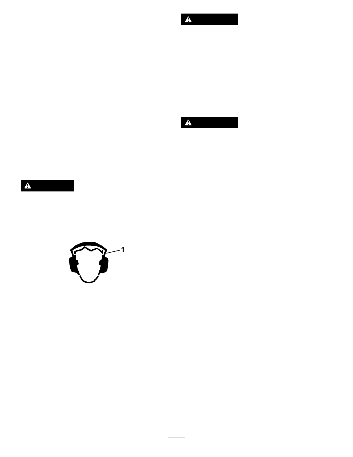
Figure18
1.Wearhearingprotection.
TowingtheMachine
Beforetowingthemachine,readalltheinformation
andperformalltheapplicableprocedurestointhis
sectiontoensuresafeandpropertowing.
TowVehicleRequirements
Beforeconnectingthemachinetoyourtowvehicle,
ensurethatyourvehicleispreparedasfollows:
g229846
•Ensurethatyourtowvehiclehastowing
capacityfortheweightofthemachine;referto
Specications(page16).
•UseaClass2orlargerreceiver.
•Ensurethatyourtowvehiclehastheappropriate
hitchtotowthemachine;optionsincludea50mm
(2inch)ballhitchorapintlehitch.
•Ifthemachineisequippedwithatrailer-lightkit,
ensurethattheelectricalconnectorofthetow
vehicleiscompatiblewiththeelectricalconnector
ofthemachine.Themachineusesastandard
4-pin,atplug.Ifyourtowvehiclehasadifferent
typeofplug,obtainanadapterfromanautomotive
partsstore.
PreparingtheMachineforTowing
1.Shutofftheengineandfuelvalve.
2.Emptythedrum.
17
Page 18
3.Positionthedruminthemixposition(upright)
andlockit.
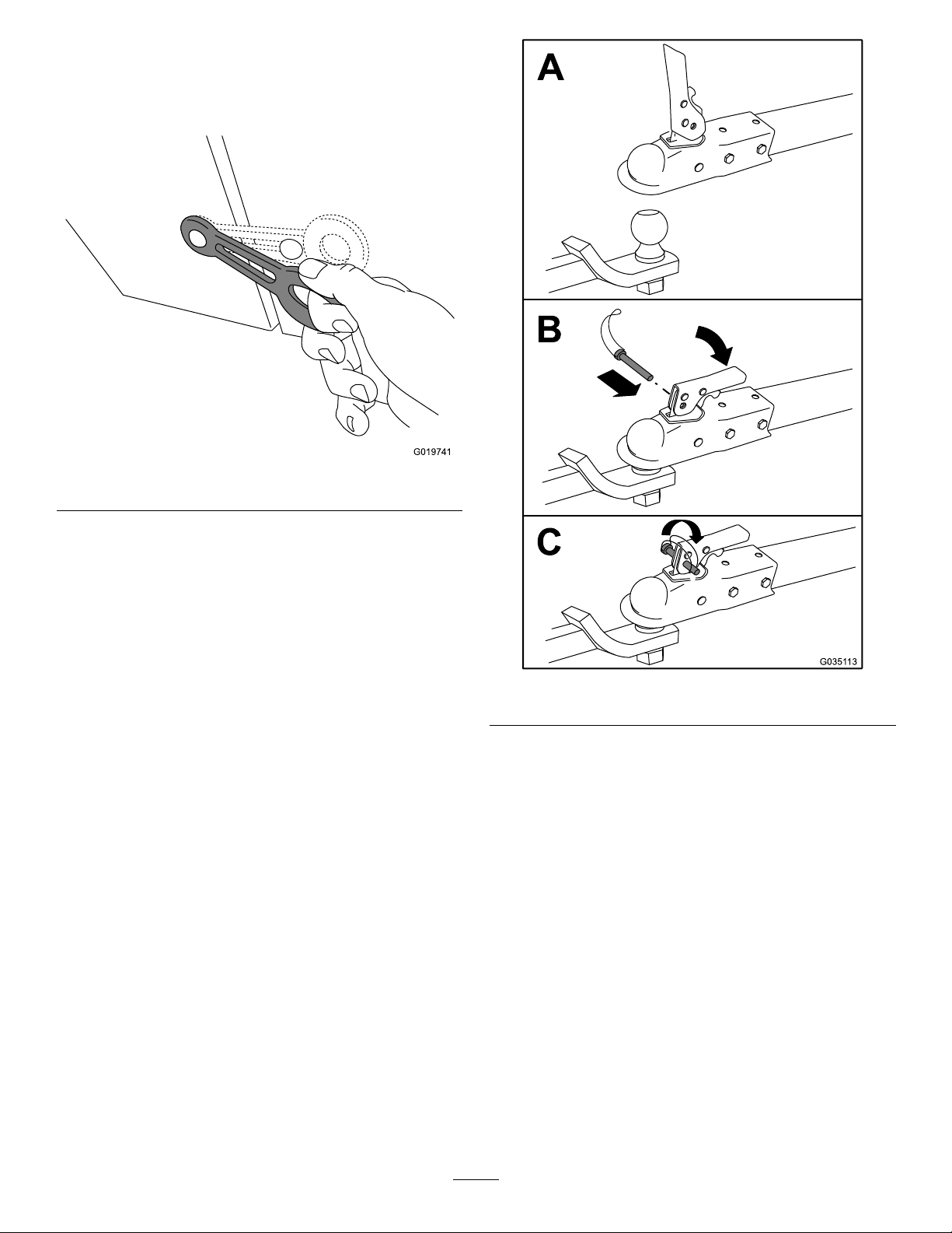
4.Closetheenginecowlandsecurethecowl
latches(Figure19).
Figure19
g019741
5.Ifyouhaveadjustedtheaxletothenarrow
position(ifequippedonyourmodel),extendthe
axle;refertoAdjustingtheAxleWidth(page20).
6.Inspectthetires;refertoInspectingtheTires
(page37).
HitchingtheMachinetoaTow Vehicle
Yourmachineisequippedwith1ofthefollowing
hitchtypes;hitchitasdescribedintheappropriate
procedure:
•Stamped-ballcoupler—HitchingaStamped-Ball
Coupler(page18)
•Forged-ballcoupler—HitchingaForged-Ball
Coupler(page18)
•Pintle-hitchcoupler—HitchingaPintle-Hitch
Coupler(page19)
HitchingaStamped-BallCoupler
1.Applychassisgreasetothesocketofthecoupler
andtheareaoftheclampthatcontactstheball.
g035113
Figure20
HitchingaForged-BallCoupler
1.Applyremovablethread-lockingcompoundto
thethreadsofthecouplerbolttopreventthe
couplerhandlefromcomingloose.
Important:Applythread-lockingcompound
asneededinthefuture.
2.Applychassisgreasetothesocketofthecoupler
andtheareaoftheclampthatcontactstheball.
3.HitchthemachineasshowninFigure21.
2.Oilthepivotpointsandslidingsurfacesofthe
couplerwithSAE30motoroil.
3.HitchthemachineasshowninFigure20.
18
Page 19
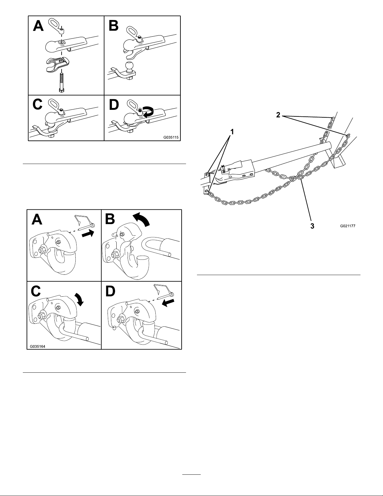
Figure21
Note:Useawrenchtokeeptheboltfrom
spinning.
HitchingaPintle-HitchCoupler
ConnectingtheSafetyChainsto theTowVehicle
1.Pullthesafetychainthroughtheslotsinthe
keyholes,sothatthelengthsoneachsideare
equal.
2.Crossbothlengthsofchainunderthetowpole.
Note:Crossingthechainsdecreasesthe
chancesofthefrontofthemachinedropping
tothegroundifthehitchdoesnotholdthe
connection.
g035115
Figure22
g021177
Figure23
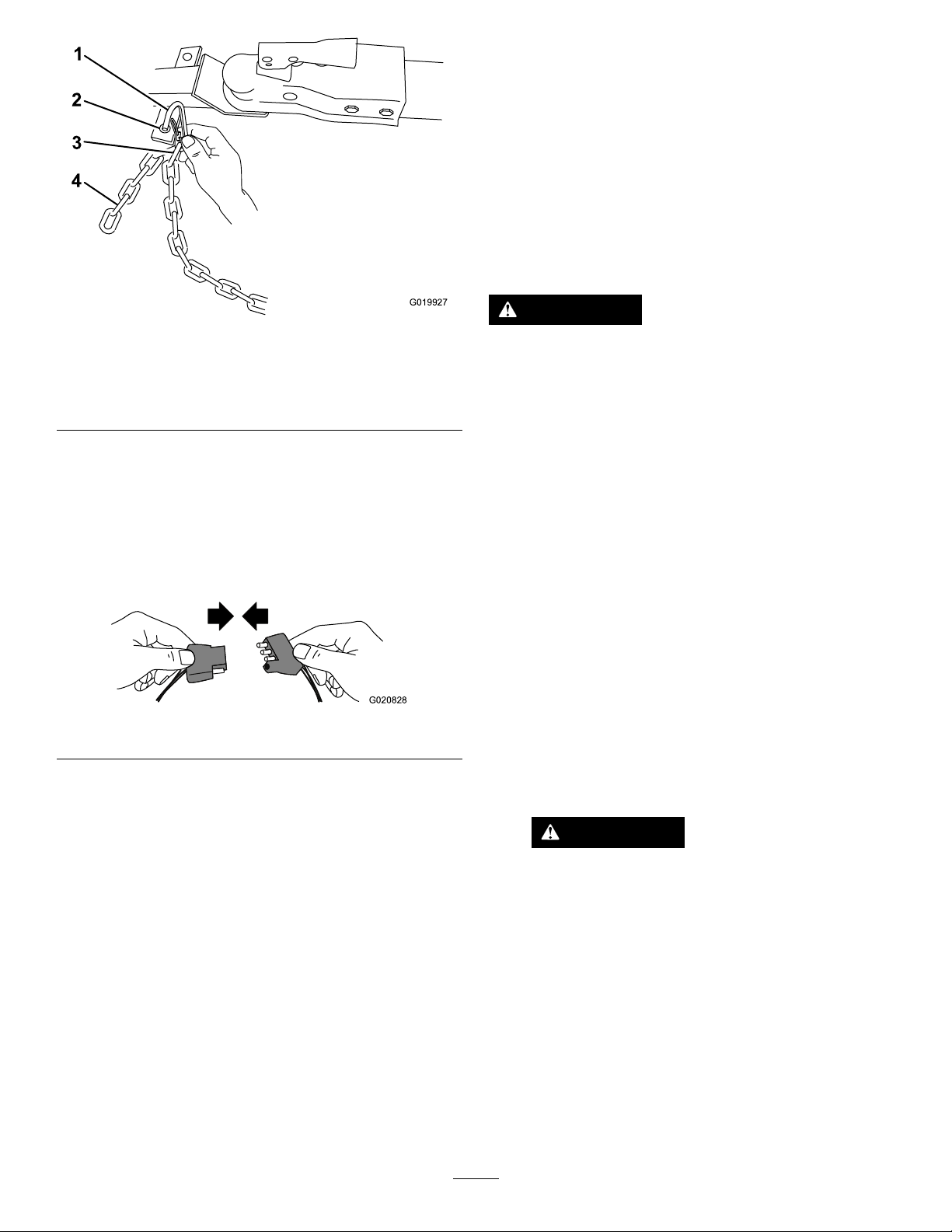
1.Connectinglinks3.Chaincrossedundertow
2.Keyholesinfrontpost
pole
3.Connecteachlengthofchaintothesafety
chainmountingpointonthetowvehiclewiththe
connectinglinks(Figure24).
Important:Ensurethatthechainhas
enoughslackforturningaroundcorners
whentowingthemachine.
Note:Stowtheexcesschaininsidethebottom
g035164
ofthefrontpostbypushingitintothekeyholes
andlatchingtheappropriatelinksintothe
keyholeslots.
19
Page 20
Thecorrespondingturn-signallightsofthe
machineshouldilluminate.
AdjustingtheAxleWidth
ModelswithAdjustableAxlesOnly
Ifyourmodelisequippedwithanadjustableaxle
(Figure27),youcanadjusttheaxletothenarrow
positiontomovethemachinethroughanarrow
accesspoint,suchasthegateofafenceorthe
doorwayofabuilding.
Figure24
1.Connectinglink3.Chainlink
2.Safetychainmounting
pointontowvehicle
4.Chain
ConnectingandCheckingthe Lights
MachinesEquippedwithaLightKitOnly
1.Connecttheelectricalplugofthemachinewith
theelectricalplugofthetowvehicle(Figure27).
Figure25
g019927
WARNING
Themachineisnotstablewhentowedwith
theaxleinthenarrowposition.
Towthemachinewiththeaxleinthewide
position.
Important:Themachineislessstablewiththe
axleinthenarrowposition.Onlyadjustittothe
narrowpositionwhennecessarytomovepastan
obstruction,thenreturnittothewideposition
beforetowingoroperatingthemachine.
1.Parkthemachineonalevelsurfaceand
disconnectthemachinefromthetowvehicle.
2.Securethemachinefrommovement.
3.Emptythedrum,moveittotheuprightposition,
andlockthedrum.
4.Alignajackwithanadequateliftheight
g020828
andweightcapacityundertheaxle;referto
Specications(page16).
5.Liftthemachineuntilthetiresareofftheground.
Note:Themachineusesastandard4-pin,at
plug.Ifyourtowvehiclehasadifferenttype
ofplug,obtainanadapterfromanautomotive
partsstore.
2.EnsurethatthetowvehicleisintheNEUTRAL
position,engagetheparkingbrake,andstart
theengine.
3.Testthelightsasfollows:
A.Turnontheheadlightsofthetowvehicle.
Thetaillightsofthemachineshould
illuminate.
B.Pressthebrakepedalofthetowvehicle.
Thebrakelightsofthemachineshould
illuminate.
C.Operateeachturnsignalofthetowvehicle
inturn.
6.Useajackstandateachsupportpointonthe
rearframeextension(Figure26).
WARNING
Mechanicalorhydraulicjacksmayfailto
supportthemachineandcauseserious
injury.
Usejackstandswhensupportingthe
machine.
20
Page 21
PreparingtoUsethe Machine
1.Parkthemachineonalevelsurfaceand
disconnectthemachinefromthetowvehicle.
2.Ensurethatallguardsandpaddlesareinplace
andingoodcondition.
3.Performalldailymaintenanceprocedures
prescribedinMaintenance(page27).
4.Chockthefrontandbackofthetirestoprevent
themachinefrommoving.
5.Movethedrumtotheuprightpositionandlockit.
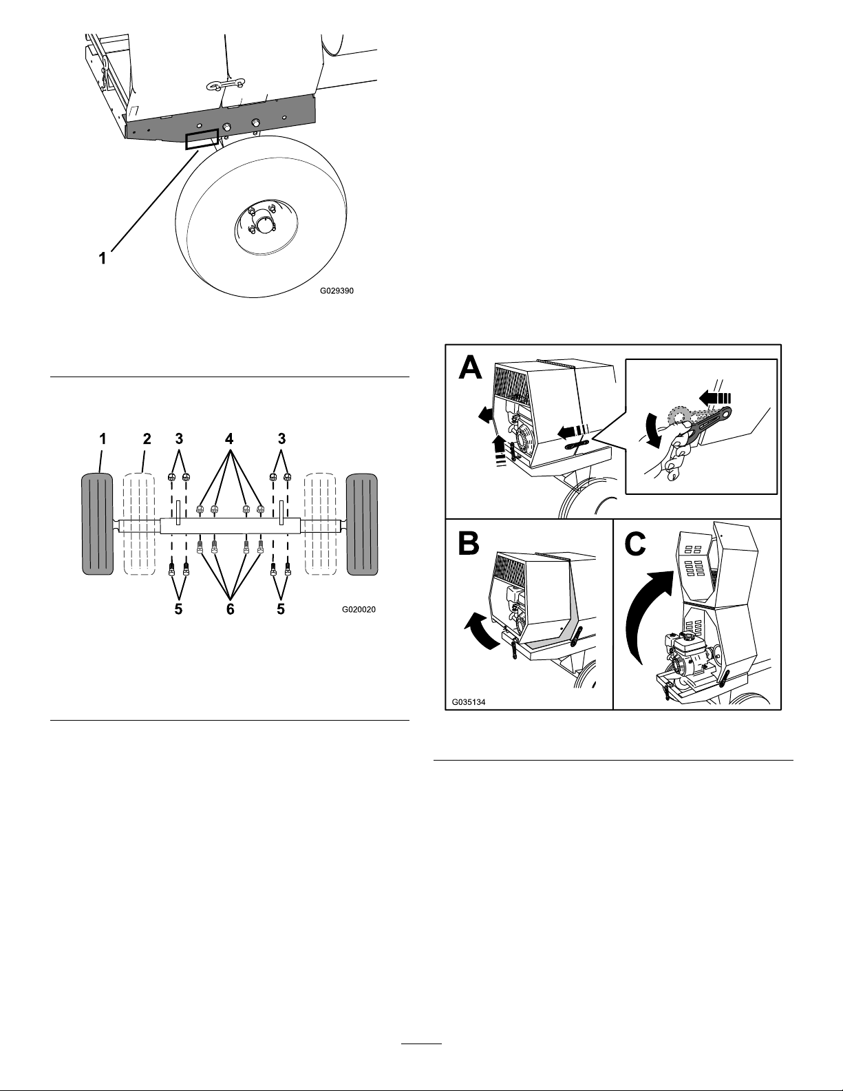
Figure26
1.Supportpoint(2)
7.Removetheboltsandnutsthatsecuretheinner
axletotheouteraxle(Figure27).
Figure27
1.Wideposition(towing)
2.Narrowposition5.Bolt—wideposition
3.Nut—wideposition6.Bolt—narrowposition
4.Nut—narrowposition
8.Aligntheinneraxletothedesiredpositionas
follows:
g029390
g020020
OpeningtheCowl
g035134
Figure28
•Slideeachsideoftheaxleinwardtothe
narrowposition(Figure27).
•Slideeachsideoftheaxleoutwardtothe
wide(tow)position(Figure27).
9.Securetheaxlewiththeboltsandnutsremoved
previously(Figure27)andtorquethemto87
N∙m(64ft-lb).
21
Page 22
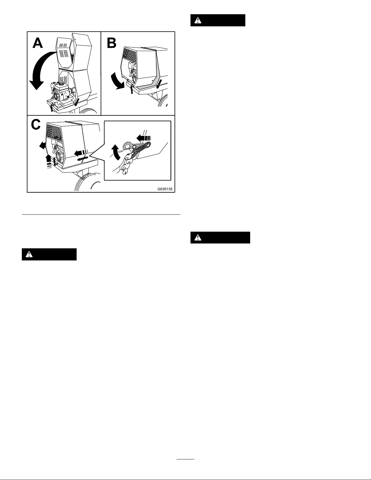
ClosingtheCowl
Figure29
DANGER
Incertainconditionsduringfueling,static
electricitycanbereleased,causingaspark
thatcanignitethefuelvapors.Areor
explosionfromfuelcanburnyouandothers
andcandamageproperty.
•Alwaysplacefuelcontainersontheground
awayfromyourvehiclebeforelling.
•Donotllfuelcontainersinsideavehicle
oronatruckortrailerbed,becauseinterior
carpetsorplastictruckbedlinersmay
insulatethecontainerandslowthelossof
anystaticcharge.
•Whenpractical,removeequipmentfrom
thetruckortrailerandrefueltheequipment
withitswheelsontheground.
•Ifthisisnotpossible,thenrefuelsuch
equipmentonatruckortrailerfroma
portablecontainerratherthanfroma
fuel-dispensernozzle.
g035135
•Ifyoumustuseafuel-dispensernozzle,
keepthenozzleincontactwiththerimof
thefueltankorcontaineropeningatall
timesuntilfuelingiscomplete.
AddingFuel
DANGER
Incertainconditions,fuelisextremely
ammableandhighlyexplosive.Areor
explosionfromfuelcanburnyouandothers
andcandamageproperty.
•Fillthefueltanksoutdoors,inanopen
area,whentheengineiscold.Wipeupany
fuelthatspills.
•Neverllthefueltanksinsideanenclosed
trailer.
•Neversmokewhenhandlingfuelandstay
awayfromanopenameorwherefuel
fumesmaybeignitedbyaspark.
•Storefuelinanapprovedcontainerand
keepitoutofthereachofchildren.Never
buymorethana30-daysupplyoffuel.
•Donotoperatewithoutentireexhaust
systeminplaceandinproperworking
condition.
WARNING
Fuelisharmfulorfatalifswallowed.
Long-termexposuretovaporscancause
seriousinjuryandillness.
•Avoidprolongedbreathingofvapors.
•Keepyourfaceawayfromthenozzleand
fueltankopening.
•Keepfuelawayfromyoureyesandskin.
FuelRecommendations
•Forbestresults,useonlyclean,fresh(lessthan
30daysold),unleadedgasolinewithanoctane
ratingof87orhigher((R+M)/2ratingmethod).
•Ethanol:Gasolinewithupto10%ethanol
(gasohol)or15%MTBE(methyltertiarybutyl
ether)byvolumeisacceptable.Ethanoland
MTBEarenotthesame.Gasolinewith15%
ethanol(E15)byvolumeisnotapprovedforuse.
Neverusegasolinethatcontainsmorethan
10%ethanolbyvolume,suchasE15(contains
15%ethanol),E20(contains20%ethanol),orE85
(containsupto85%ethanol).Usingunapproved
gasolinemaycauseperformanceproblemsand/or
enginedamagewhichmaynotbecoveredunder
warranty.
•Donotusegasolinecontainingmethanol.
22
Page 23
•Donotstorefueleitherinthefueltankorinfuel
containersoverthewinterunlessyouuseafuel
stabilizer.
•Donotaddoiltogasoline.
Important:T oreducestartingproblems,addfuel
stabilizertothefuelallseason,mixingitwithfuel
lessthan30daysold;runthemachinedrybefore
storingitformorethan30days.
Donotusefueladditivesotherthanafuel
stabilizer/conditioner.Donotusefuelstabilizers
withanalcoholbasesuchasethanol,methanol,
orisopropanol.
FuelTankCapacity
Important:Thisspaceinthetankallows
fueltoexpand.Donotllthefueltank
completelyfull.
Model
68013and68014
68016,68017,68020,68021
68024
FuelTankCapacity
3.1L(0.82USgallons)
5.3L(1.40USgallons)
6.1L(1.61USgallons)
FillingtheFuelTank
1.Parkthemachineonalevelsurface,shutoffthe
engine,andallowtheenginetocool.
2.Cleanaroundthefuelcapandremoveit(Figure
30).
g020679
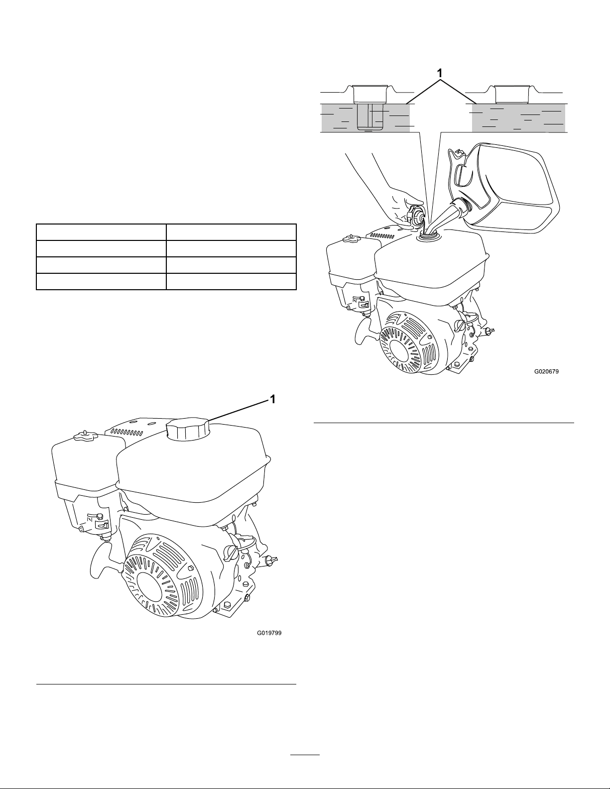
Figure31
1.Maximumfuellevel
4.Installthefuelcapsecurely(Figure30).
5.Wipeupanyspilledfuel.
Figure30
1.Fuelcap
3.Addfueltothefueltankuntilthelevelisatthe
maximumfuellevel(Figure31).
g019799
23
Page 24
PerformingDaily Maintenance
Beforestartingthemachineeachday ,performthe
EachUse/DailyprocedureslistedinMaintenance
(page27).
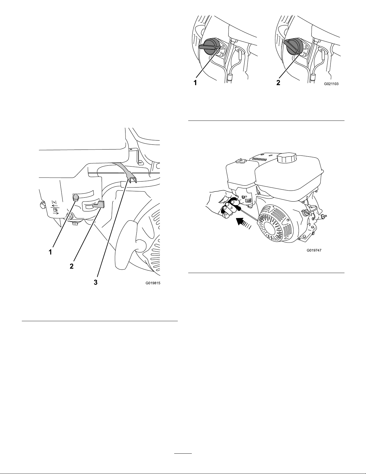
StartingtheEngine
1.EnsurethattheclutchleverisintheOFF
position.
2.MovethefuelvalvetotheOPENposition,allthe
waytotheright(Figure32).
Figure33
1.Engineswitch—OFF
position
6.Pullthestarterhandlelightlyuntilyoufeel
resistance,thenpullthehandlebriskly(Figure
34).Returnthestarterhandlegently.
2.Engineswitch—ON
position
Figure34
g021103
g019747
Figure32
1.Chokelever
2.Fuelvalve
3.MovethechokelevertotheONposition(Figure
32).
3.Throttlelever
Note:Awarmorhotenginemaynotrequire
choking.
4.Movethethrottlelever1/3ofthewaytowardthe
MAXposition.
5.MovetheengineswitchtotheONposition
(Figure33).
g019815
7.Aftertheenginestarts,graduallymovethe
chokeleverbacktotheOFFposition.Ifthe
enginestallsorhesitates,movethechokeback
totheONpositionagainuntiltheenginewarms
up.ThenmoveittotheOFFposition.
ShuttingOfftheEngine
1.MovethethrottlelevertotheMINposition
(Figure15).
Note:Iftheenginehasbeenworkinghardor
ishot,letitidleforaminutebeforeshuttingoff
theengine.Thishelpstocooltheenginebefore
stopping.Inanemergency,shutofftheengine
immediately.
2.MovetheengineswitchtotheOFFposition.
3.MovethefuelvalvetotheCLOSEDposition,all
thewaytotheleft.
24
Page 25
MixingtheMaterial
DANGER
Eyeandskincontactwithconcretematerials
andbreathingthedustinvolvedishazardous
toyourhealth.
•Ensurethatthereisadequateair
ventilation.
•Wearadustmasktopreventinhalationof
dustwhileusingthemachine;refertoSafe
OperatingPractices(page4).
•Avoiddirectcontactofcementand
concretematerialswithskinandeyes.
DANGER
Thismachineiscapableofamputatinghands.
•Stayintheoperator’spositionwhilethe
machineisrunning.
g019873
Figure35
Belt-DriveModels
1.OFFposition2.ONposition
•Keepallbystandersasafedistanceaway
fromthemachine.
•Stopthemachineimmediatelyifany
peopleoranimalsentertheworkarea.
•Neverplaceanypartofyourbodyintoa
positionthatcausesanunsafeoperating
condition.
Important:Donotaddmorematerialthan
thebatchcapacityofthemachine;referto
Specications(page16).
Note:Followthemanufacturer’sinstructionsthatare
printedonthepackagingoftheproductyouareusing.
1.Ensurethatthereisnoold,loosematerialin
thedrumthatcancontaminatethebatchof
material;refertoCleaningtheDrum(page26)
andDumpingtheMaterial(page26),thenreturn
thedrumtotheuprightposition.
Note:Ensurethatthedrumisinthemix
position(upright)andthedrumlatchisengaged.
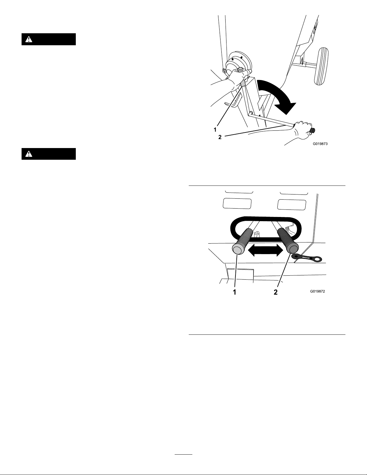
2.MovetheclutchlevertotheOFFposition(Figure
35orFigure36).
g019872
Figure36
GearboxModels
1.ONposition2.OFFposition
6.Addtheingredientsforthebatchasfollows:
A.Pourwaterintothedrumthroughthegrate.
B.Addtheplaster,cement,orotherbinding
material.
3.Starttheengine.
Note:Allowtheenginetowarmupat2/3
throttlefor1to2minutes.
4.SetthethrottleleverontheenginetotheMAX
position.
5.MovetheclutchlevertotheONposition(Figure
35orFigure36).
Note:Youcanopenbagsofcement,
plaster,andbindingmaterialsbylowering
thebagontothebagsplitter(Figure37).
25
Page 26
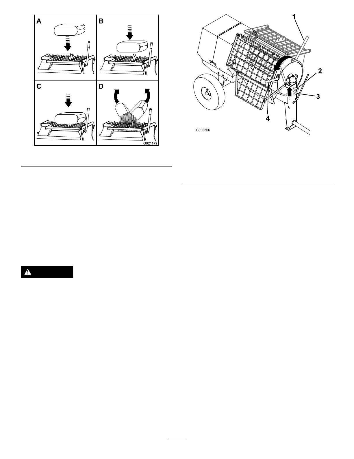
Figure37
C.Ifyouareusingsandand/orother
reinforcingmaterials,addthemintothe
drum.
7.Allowthepaddlestomixthematerialuntilthe
ingredientshaveauniformappearance.
Note:Ifneeded,addwaterorplaster,cement,
orotherbindingmaterialuntiltheconsistency
ofthebatchiscorrect.
DumpingtheMaterial
DANGER
Contactwiththemixingpaddlescouldcause
damageorinjury.
g035366
g021179
1.Dumphandle—Mix
position
2.Drumlatch—Release
position
Figure38
3.Drumlatch—Locked
position
4.Dumphandle—Dump
position
3.Liftthehandleofthedrumlatch(Figure38).
4.Withbothhandsonthedumphandle,rotateit
counterclockwisetodischargethecontentsof
thedrum(Figure38).
Note:Allowthemachinetocompletely
dischargethecontentsofthedrum.
5.Rotatethedumphandleclockwiseuntilthe
drumlatchlocksthedrumintheuprightposition
(Figure38).
6.Afterdumpingabatchofmaterial,clean
thedrumtopreventdriedmaterialfrom
contaminatingthenextbatchofmaterial;referto
CleaningtheDrum(page26).
Neverputyourhandsinsidethedrumwhile
theengineisrunning.
Note:Whendumpingabatchofmaterial,leave
theengine/motorrunningandtheclutchintheON
positionsothattherotatingpaddleshelpdischarge
thematerial.
1.Alignawheelbarroworsimilarcontainerof
adequatecapacityinthepathofthedrum
opening.
2.Graspthedumphandlewithyourlefthand
(Figure38).
CleaningtheDrum
Important:Donotstrikeonthedrumwitha
shovel,hammer,oranyotherdevicetoloosenany
accumulateddriedmaterials.
1.MovetheclutchlevertotheOFFpositiontostop
thepaddles.
2.Shutofftheengine/motor.
3.Ensurethatthedrumisinthemixposition
(upright).
4.Spraythemachinewithwatertoremoveany
accumulatedmaterial.
5.Starttheengine/motor.
6.MovetheclutchlevertotheONpositiontostart
thepaddles.
7.Dumpthedrum.
26
Page 27
Maintenance
WARNING
Failuretoproperlymaintainthemachinecouldresultinprematurefailureofmachinesystems
causingpossibleharmtoyouorbystanders.
Keepthemachinewellmaintainedandingoodworkingorderasindicatedintheseinstructions.
Important:Refertoyourengineoperator'smanualforadditionalmaintenanceprocedures.
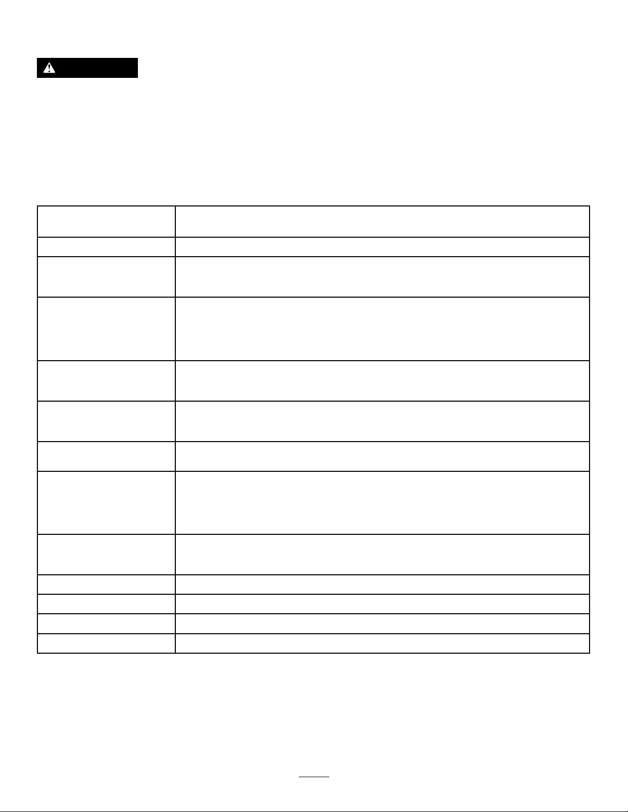
RecommendedMaintenanceSchedule(s)
MaintenanceService
Interval
Aftertherst20hours
Aftertherst25hours
Beforeeachuseordaily
Aftereachuse
Every40hours
Every50hours
Every100hours
MaintenanceProcedure
•Changethereduction-caseoil(Models68013and68014only).
•Changetheengineoil.
•Checktheclutchoperation(gearboxmodelonly).
•Inspectthebeltsandadjustasnecessary(belt-drivemodelsonly).
•Inspecttheair-cleanerelements.
•Checktheengine-oillevel.
•Inspectthetires.
•Checkthereduction-caseoil(Models68013and68014only).
•Checktheclutchoperation(gearboxmodelonly).
•Cleanthedrumbetweenmixingbatchesofmaterial.
•Lubricatethetrunnions.
•T orquethewheellugnutsto108to122N∙m(80to90ft-lb)aftertowing.
•Checkthegearboxoil(gearboxmodelonly).
•Inspectthebeltsandadjustasnecessary(belt-drivemodelsonly).
•Checktheclutchoperation
•Cleantheair-cleanerelements.Cleanthemmorefrequentlyindustyoperating
conditions.
•Changetheengineoil.
•Checkthesparkplug.
•Cleanthesparkarrester(ifequipped).
•Cleanthefuel-sedimentcup.
•Changethereduction-caseoil(Models68013and68014only).
Every300hours
Every800hours
Yearlyorbeforestorage
Every2years
•Replacethepaperair-cleanerelement.Replaceitmorefrequentlyindusty
operatingconditions.
•Replacethesparkplug.
•Replacethegearboxoil(gearboxmodelsonly).
Monthly
•Lubricatethepillow-blockbearings.
•Cleanthefuel-sedimentcup.
•Replacethebelts(belt-drivemodelsonly).
27
Page 28
Pre-Maintenance
Procedures
PreparingtheMachinefor Maintenance
1.Shutofftheengineandallowittocool
completely.
2.Parkthemachineonalevelsurface.
3.Removethemachinefromthetowvehicle.
4.Securethemachinefrommovement.
5.Disconnectthespark-plugwire.
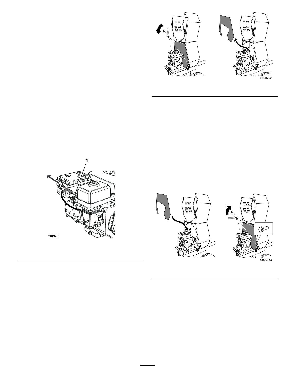
g020752
Figure40
3.Toremovethedividerplate,liftitupwardandtilt
itbacksothatitclearsvariouscomponents.
Disconnectingthe Spark-PlugWire
Pullthespark-plugwireofftheterminalofthespark
plug(Figure39).
Figure39
1.Sparkplug
InstallingtheDividerPlate
Whennishedperformingmaintenance,installthe
dividerplateasfollows:
1.Guidethedividerplateintopositionagainstthe
frontcowl.
Note:Startwiththedividerplaterotatedslightly
counterclockwise,andthenrotateitclockwise
whileloweringitintoposition.
Ensurethatthedividerplateisnotbackward.
g019281
g020753
Figure41
RemovingtheDividerPlate
Ifyourmodelhasadividerplate,youmayneed
toremoveitbeforeperformingsomemaintenance
procedures:
1.Openthecowl.
2.Useawrenchtoremovethe4boltsthatsecure
thedividerplatetothefrontcowl.
Note:Retainthefastenersforinstallingthe
dividerplate.
2.Aligntheboltholesinthedividerplateandthe
frontcowl.
3.Installeachofthe4bolts,andhand-tighten
themtopreventcross-threading.
4.Tightentheboltswithawrenchuntiltheyare
secure.
28
Page 29
Lubrication
LubricatingtheBearings andSeals
ServiceInterval:Aftereachuse—Lubricatethe
trunnions.
Monthly—Lubricatethepillow-blockbearings.
Note:Thepillow-blockbearingsareinsidethe
cowl—removethedividerplateifequipped)toaccess
them;refertoRemovingtheDividerPlate(page28).
GreaseType:No.2lithiumgrease.
1.CompletetheprocedureslistedinPreparingthe
MachineforMaintenance(page28).
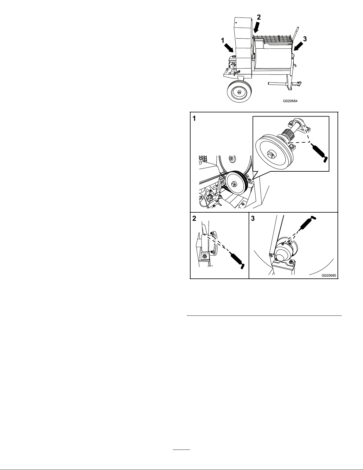
2.Cleantheareaaroundeachgreasettingwitha
ragandlifttheplasticcapoffthegreasetting
(Figure42).
g020684
Figure42
1.Pillow-blockbearings3.Fronttrunnion
2.Reartrunnion
3.Pumpgreaseintoeachttingasfollows:
•Forthepillow-blockbearings,pump1shotof
greaseintoeachtting(Figure42).
•Forthetrunnions,pumpseveralshotsof
greaseintoeachttinguntilitstartstoooze
outofthebearinghousing(Figure42).
Important:Pumpgreaseinslowlyand
carefullytopreventdamagetothebearing
seals.
4.Wipeupanyexcessgrease.
g020685
29
Page 30
EngineMaintenance
ServicingtheAirCleaner
ServiceInterval:Beforeeachuseordaily—Inspect
theair-cleanerelements.
Every50hours—Cleantheair-cleaner
elements.Cleanthemmorefrequentlyindusty
operatingconditions.
Every300hours/Y early(whichevercomes
rst)—Replacethepaperair-cleanerelement.
Replaceitmorefrequentlyindustyoperating
conditions.
Important:Donotoperatetheenginewithout
theair-lterassembly;extremeenginedamage
willoccur.
1.Shutofftheengineandwaitforallmovingparts
tostop.
2.Disconnectthewirefromthesparkplug;referto
DisconnectingtheSpark-PlugWire(page28).
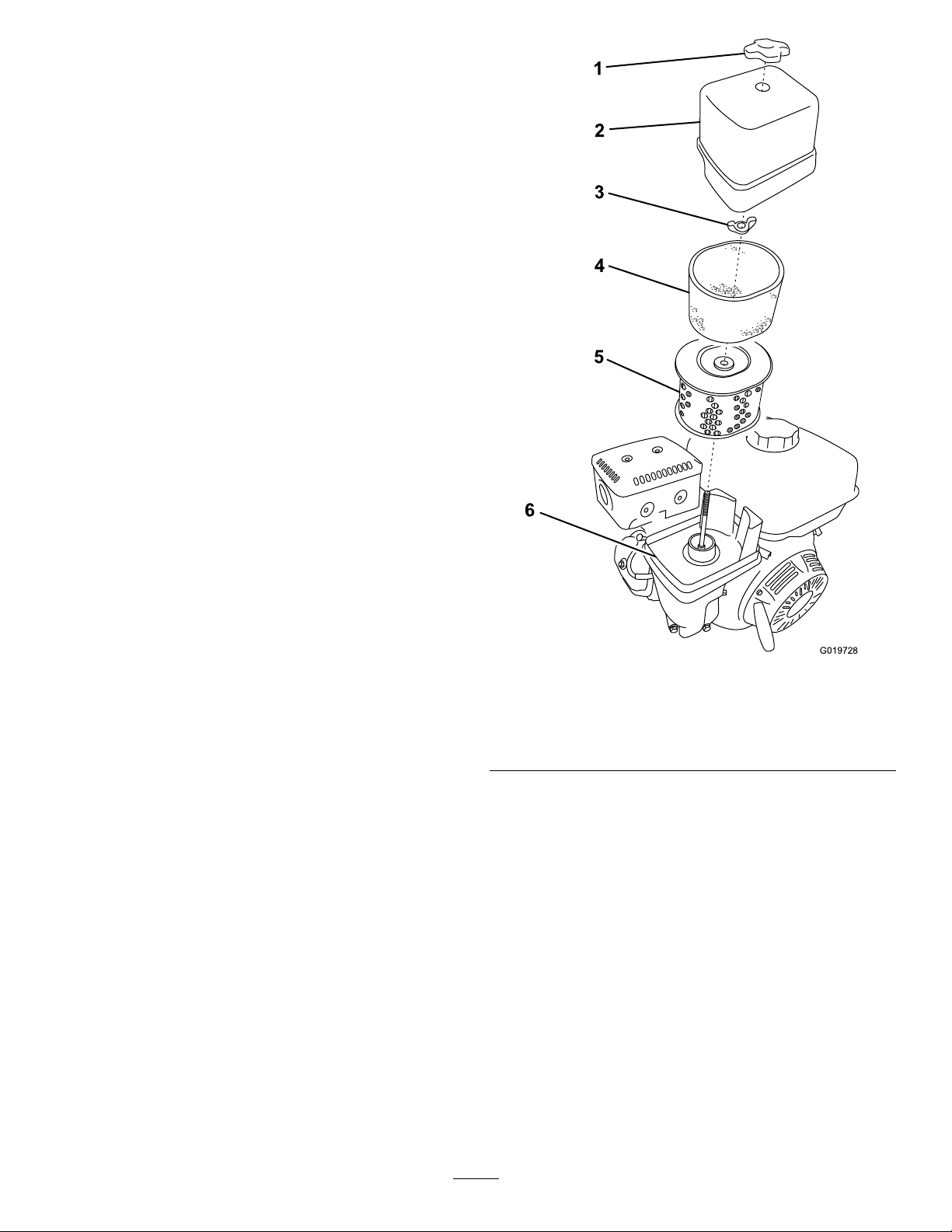
3.Removethenutthatsecuresthecover(Figure
43).
Figure43
1.Covernut
2.Cover
3.Wingnut6.Base
4.Removethecover.
4.Foamelement
5.Paperelement
Note:Becarefultopreventdirtanddebrisfrom
fallingintothebase.
5.Removethefoamandpaperelementsfromthe
base(Figure43).
6.Removethefoamelementfromthepaper
element(Figure43).
7.Inspectthefoamandpaperelementsand
replacethemiftheyaredamagedorexcessively
dirty.
Note:Nevertrytobrushdirtoffthepaper
element;brushingforcesthedirtintothebers.
8.Cleanthefoamelementinwarm,soapywater
orinanonammablesolvent.
g019728
Note:Donotusefueltocleanthefoamelement
becauseitcouldcreateariskofreorexplosion.
30
Page 31
9.Rinseanddrythefoamelementthoroughly .
10.Dipthefoamelementincleanengineoil,then
squeezeouttheexcessoil.
Note:Excessoilinthefoamelementrestricts
theairowthroughtheelementandmayreach
thepaperlterandclogit.
11.Wipedirtfromthebaseandthecoverwitha
moistrag.
Note:Becarefultopreventdirtanddebrisfrom
enteringtheairductleadingtothecarburetor.
12.Installtheair-cleanerelementsandensurethat
theyareproperlypositioned.
13.Securelyinstallthecoverwiththenut.
ServicingtheEngineOil
Engine-OilSpecications
ToroPremiumEngineOilisavailablefromyour
AuthorizedT oroDealer.
CheckingtheEngine-OilLevel
ServiceInterval:Beforeeachuseordaily
1.Parkthemachineonalevelsurfaceandshut
offtheengine.
2.Allowtheenginetocool.
3.Disconnectthewirefromthesparkplug;referto
DisconnectingtheSpark-PlugWire(page28).
4.Cleanaroundthedipstick.
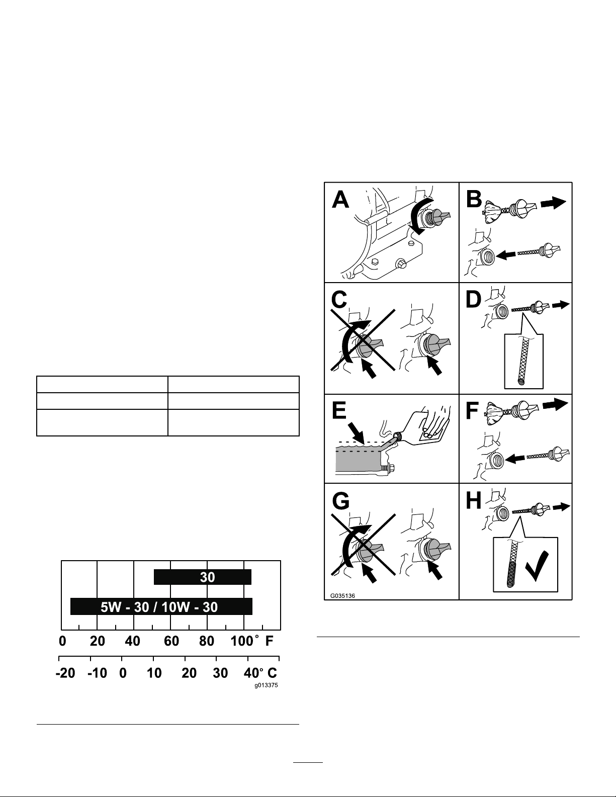
5.ChecktheoillevelasshowninFigure45.
Important:Use4-cycleengineoilthatmeetsor
exceedstherequirementsforAPIservicecategory
SJ,SL,SM,orhigher.
Model(s)CrankcaseCapacity
68013and68014
68016,68017,68020,68021,
68024
0.58L(0.61USqt)
1.1L(1.2USqt)
Important:Iftheoillevelinthecrankcaseistoo
lowortoohighandyouruntheengine,youmay
damagetheengine.Thistypeofdamageisnot
coveredbythewarranty.
Note:UseSAE10W-30forgeneraluse.Youcan
usetheotherviscositiesshowninthechartwhen
theaveragetemperatureinyourareaiswithinthe
indicatedrange(Figure44).
g035136
Figure45
Figure44
ChangingtheEngineOil
g013375
ServiceInterval:Aftertherst25hours
Every100hours
31
Page 32
WARNING
Oilmaybehotaftertheenginehasbeenrun,
andcontactwithhotoilcancausesevere
personalinjury.
Avoidcontactingthehotengineoilwhenyou
drainit.
1.Shutofftheengineandwaitforallmovingparts
tostop.
2.Disconnectthewirefromthesparkplug;referto
DisconnectingtheSpark-PlugWire(page28).
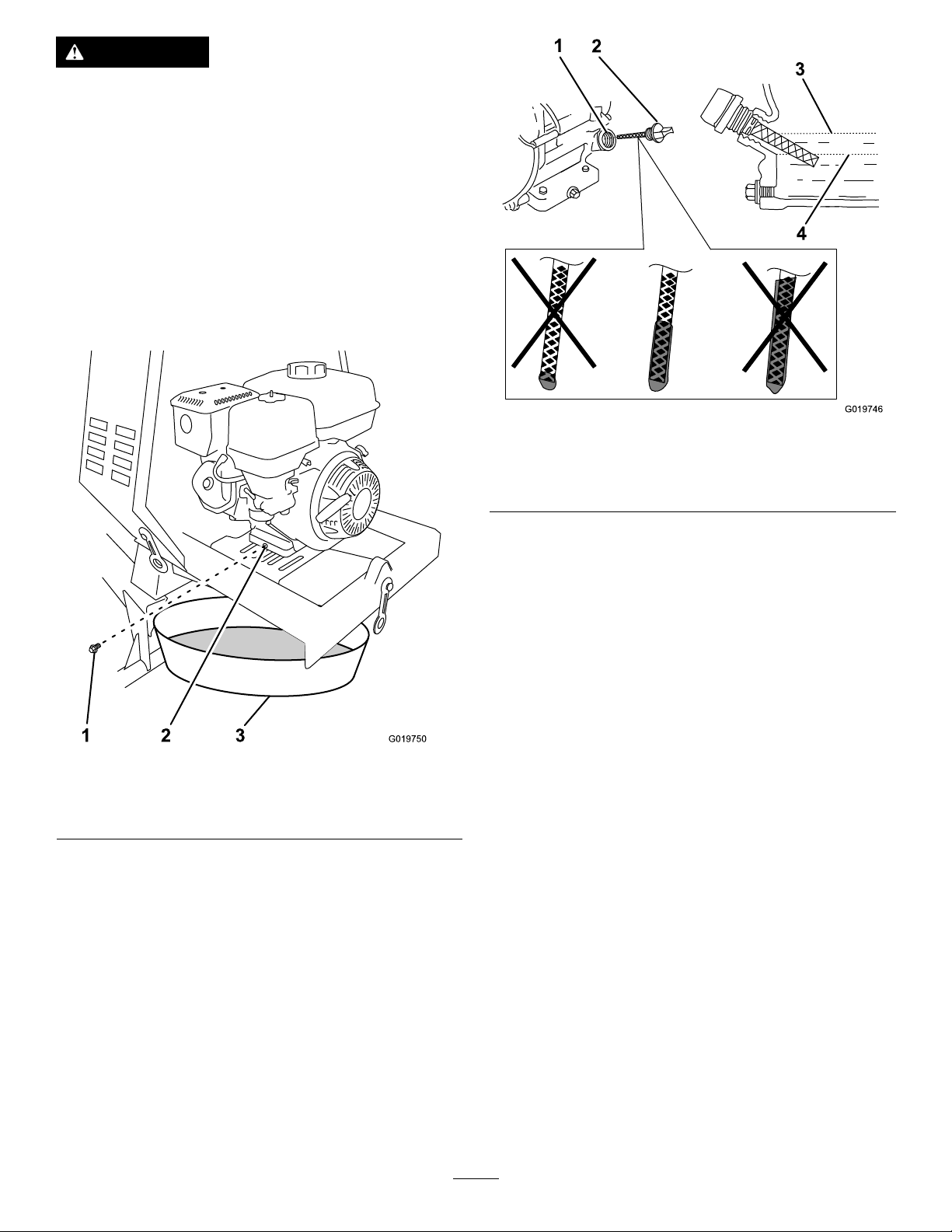
3.Placeadrainpanundertheoil-drainholeofthe
engine(Figure46).
Figure47
1.Oil-llhole3.Oil-levelupperlimit
2.Dipstick
4.Oil-levellowerlimit
g019746
Figure46
1.Oil-drainplug3.Oil-drainpan
2.Oil-drainhole
4.Removethedrainplugandcatchtheoilinthe
oil-drainpan(Figure46).
5.Whentheoilhasdrainedcompletely,installthe
drainplugwithanewwasher(Figure46).
Note:Disposeoftheusedoilatacertied
recyclingcenter.
7.Replaceandsecurethedipstick.
8.Wipeupanyspilledoil.
g019750
6.Removethedipstick(Figure47)andslowly
pouroilintothellholeuntiltheoilreachesthe
upper-limitmark(bottomedgeoftheoil-llhole)
onthedipstick.
32
Page 33
ServicingtheSparkPlug
ServiceInterval:Every100hours/Every6months
(whichevercomesrst)—Checkthe
sparkplug.
Every300hours/Y early(whichevercomes
rst)—Replacethesparkplug.
SparkPlugSpecications
Type:NGKBPR6ESorequivalent
Gap:0.7to0.8mm(0.028to0.031inch)
Note:Usea21mm(13/16inch)spark-plugwrench
forremovingandinstallingthesparkplug.
RemovingtheSparkPlug
1.Parkthemachineonalevelsurfaceandshut
offtheengine.
2.Ensurethatthemachinesurfacesarecool.
3.Pullthespark-plugwireofftheterminalofthe
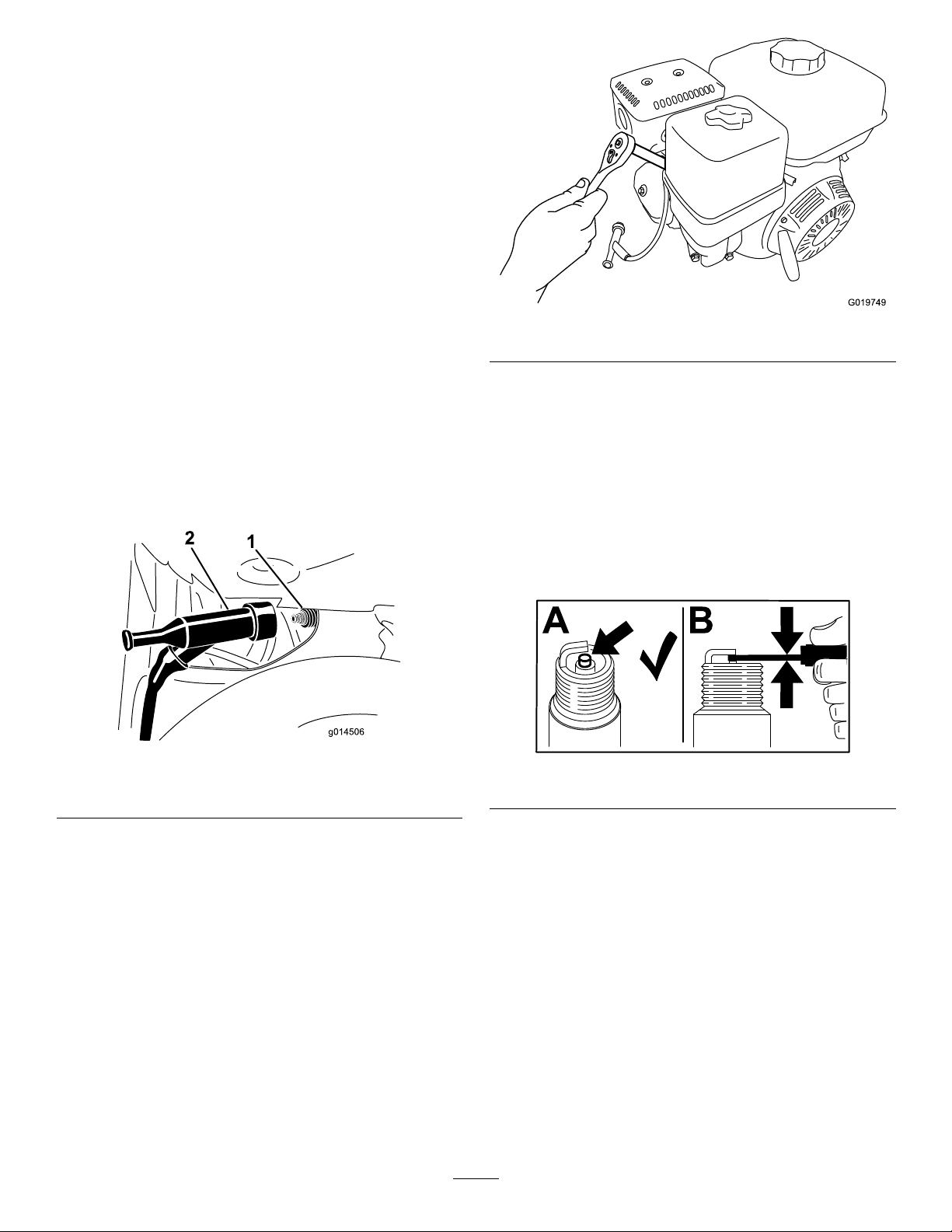
sparkplug(Figure48).
g019749
Figure49
CheckingtheSparkPlug
Important:Donotcleanthesparkplug.Always
replacethesparkplugwhenithasablackcoating,
wornelectrodes,anoilylm,orcracks.
Note:Ifyouseelightbrownorgrayontheinsulator,
theengineisoperatingproperly.Ablackcoatingon
theinsulatorusuallymeansthattheaircleanerisdirty.
Figure48
1.Sparkplug
4.Cleanaroundthesparkplug.
5.Rotatethesparkplugcounterclockwiseusing
a21mm(13/16inch)spark-plugwrenchto
removetheplugandthesealingwasher(Figure
49).
2.Wire
Setthegapto0.7to0.8mm(0.028to0.031inch).
g014506
Figure50
g206628
33
Page 34
InstallingtheSparkPlug
CleaningtheSparkArrester
Important:Ensurethatthegapbetweentheside
andcenterelectrodesiscorrectbeforeinstalling
thesparkplug.
1.Threadthesparkplugclockwiseintothe
spark-plugholebyhand.
Note:Avoidcross-threadingthesparkplugwith
thethreadsofthespark-plughole.
2.Rotatethesparkplugclockwiseusinga21mm
(13/16inch)spark-plugwrenchuntiltheplug
andsealingwasherareseated(Figure49).
3.Tightenthesparkplugasfollows:
•Wheninstallinganin-servicesparkplug,
tightenthepluganadditional1/8to1/4turn.
•Wheninstallinganewsparkplug,tightenthe
pluganadditional1/2turn.
Important:Aloosesparkplugmaycause
thecylindertooverheat.Anover-tightspark
plugmaydamagethethreadsinthecylinder
head.
4.Pushthespark-plugwireontotheterminalofthe
sparkplug(Figure48).
ServiceInterval:Every100hours
Note:Asparkarresterisavailableasanoption.If
yourequireasparkarrester,contactyourAuthorized
ServiceDealer.GenuineT orosparkarrestersare
approvedbytheUSDAForestryService.
WARNING
Iftheenginehasbeenrunning,themufer
willbehot.Contactwithhotsurfacesmay
causepersonalinjury.
Keepyourhands,feet,face,clothingand
otherbodypartsawayfromthemuferand
otherhotsurfacesuntiltheyhavecooled.
1.Parkthemachineonalevelsurfaceandshut
offtheengine.
2.Allowtheenginetocool.
3.Disconnectthewirefromthesparkplug;referto
DisconnectingtheSpark-PlugWire(page28).
4.Removethedividerplate(ifequipped);referto
RemovingtheDividerPlate(page28).
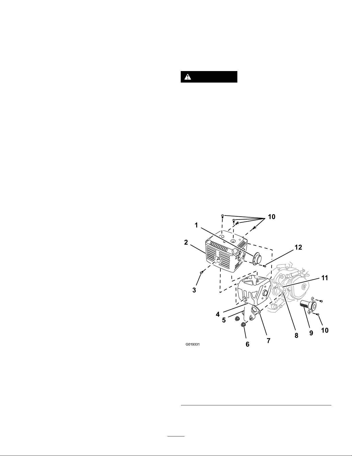
5.Removethe2nuts(8mm)andremovethe
muferfromthecylinder(Figure51).
Figure51
1.Deector(if
applicable)
2.Protector
3.Screw(6mm)7.Gasket
4.Mufer8.Bolt(8mm)12.Screw(4mm)
6.Removethe3screws(4mm)fromtheexhaust
deector,andremovethedeector(Figure51).
34
5.Exhaustpipe
6.Nut(8mm)10.Screws(5mm)
g019331
9.Sparkarrester
11.Exhaustport
Page 35
7.Removethescrews(5mmand6mm)from
themuferprotector,andremovethemufer
protector(Figure51).
8.Removethescrews(4mm)fromthespark
arrester,andremovethesparkarresterfromthe
mufer(Figure51).
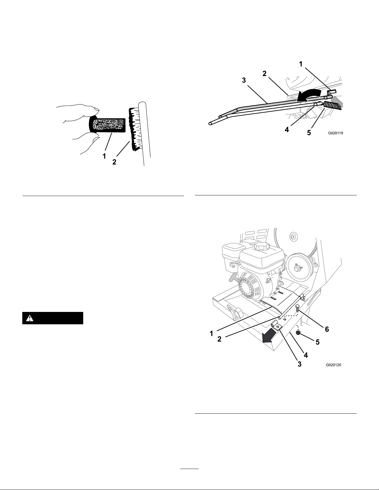
9.Useabrushtocarefullyremovecarbondeposits
fromthespark-arresterscreen(Figure52).
Note:Replacethesparkarresterifithas
breaksorholes.
7.Usingaspring-removaltool(T oroPartNo.
92-5771),removethespringfromtheanchor
bracketontheenginedeck(Figure53).
Note:Leavetheotherendofthespring
attachedtotheframeofthemachine.
g020119
Figure53
Figure52
1.Screen
2.Brush
10.Installthesparkarrester,muferprotector,
exhaustdeector,andmuferinthereverse
orderofdisassembly.
11.Installthedividerplate(ifequipped);referto
InstallingtheDividerPlate(page28).
RemovingandInstalling theEngine
Belt-DriveModelsOnly
RemovingtheEngine
WARNING
Thespringisundertensionwheninstalled
andcancausepersonalinjury .
1.Anchorbracket
g208746
2.Enginedeck
3.Spring-removaltool(T oro
PartNo.92-5771)
4.Spring-removaltool
(springremoved)
5.Spring(springremoved)
8.Removetheboltandnutthatsecuretherear
bracketfortheenginedeckhingetotheframe
ofthemachine(Figure54).
Becarefulwhenremovingthespring.
1.Parkthemachineonalevelsurfaceandshut
offtheengine.
2.Allowtheenginetocool.
3.Disconnectthewirefromthesparkplug;referto
DisconnectingtheSpark-PlugWire(page28).
4.Removethedividerplate;refertoRemovingthe
DividerPlate(page28).
5.Removethebeltguide;refertoRemovingthe
Belts(page43).
6.Removethebelts;refertoRemovingtheBelts
(page43).
g020120
Figure54
1.Enginedeck4.Frame
2.Pivot5.Nut
3.Rearhingebracket6.Bolt
9.Liftuptherearedgeoftheenginedeckand
removethehingebracket(Figure54).
10.Slidetheenginedeckrearwardandoutfromthe
forwardhingebracket(Figure55).
35
Page 36
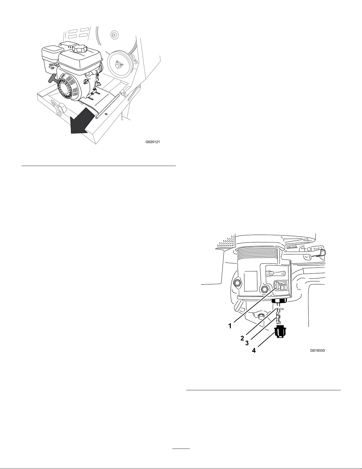
Note:Donotremovetheforwardhingebracket.
Figure55
11.Removetheengineandenginedeckfromthe
machine(Figure55).
InstallingtheEngine
1.Aligntheengineandenginedecktotherear
frameofthemachine.
Note:Thedrivepulleyontheenginemustalign
forward.
FuelSystem
Maintenance
CleaningtheFuel-Sediment Cup
ServiceInterval:Every100hours/Every6months
(whichevercomesrst)—Cleanthe
fuel-sedimentcup.
Yearlyorbeforestorage—Cleanthe
fuel-sedimentcup.
Underneaththefuelvalveisasedimentcuptocatch
dirtinthefuel.
1.Parkthemachineonalevelsurfaceandshut
g020121
offtheengine.
2.Allowtheenginetocool.
3.Disconnectthewirefromthesparkplug;referto
DisconnectingtheSpark-PlugWire(page28).
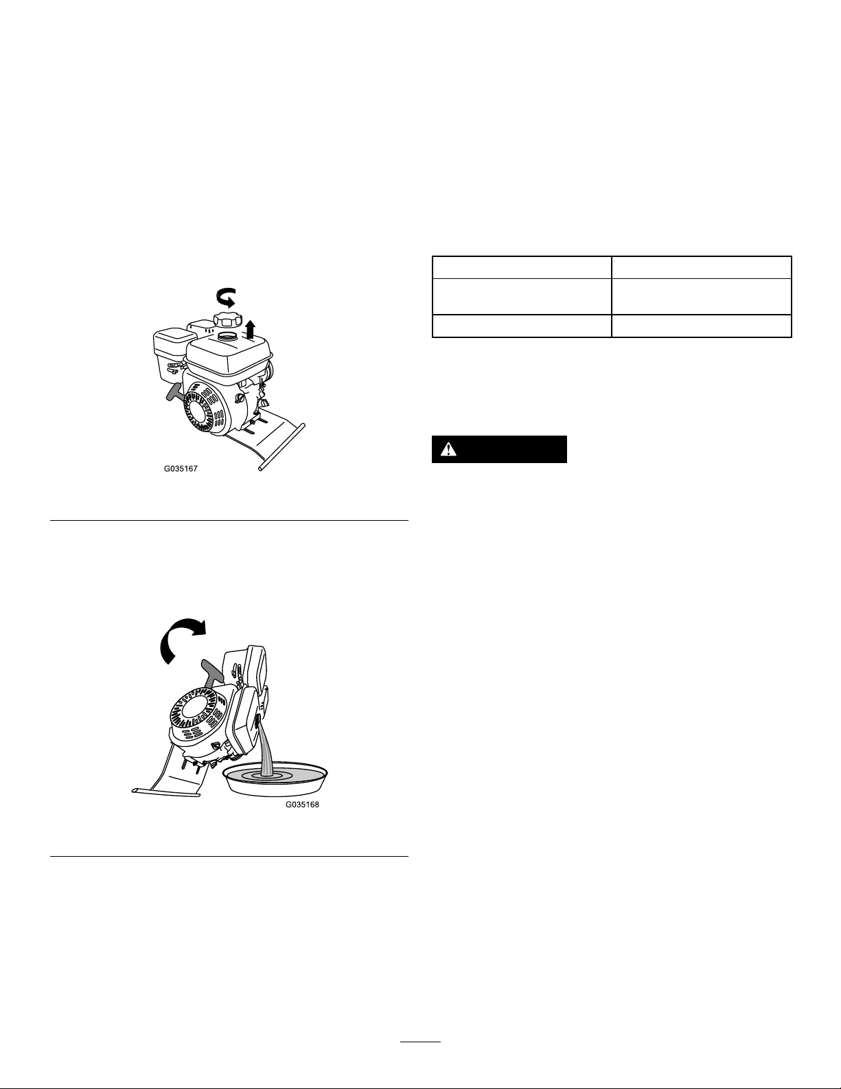
4.MovetheleverofthefuelvalvetotheOFF
position,allthewaytotheleft(Figure56).
5.Unscrewthefuel-sedimentcup(Figure56).
6.RemoveandretainthefuellterandO-ring
(Figure56).
Note:DonotcleantheO-ringinsolvent.
2.Alignthepivotontheenginedeckwiththe
forwardhingebracket(Figure55).
3.Slidetheenginedeckforwardandthepivotinto
theforwardhingebracket(Figure55).
4.Aligntherearhingebracketwiththepivotonthe
engine-deckhinge(Figure55).
5.Liftupontherearedgeoftheenginedeckand
slipthehingebracketontothepivot.
6.Securetherearbrackettotheframeofthe
machineusingtheboltandnut(Figure54)
removedinstep8ofRemovingtheEngine
(page35).
7.Usingaspring-removaltool(T oroPartNo.
92-5771),installthetensionspringtotheanchor
bracketontheenginedeck(Figure53).
8.Installthebeltsandbeltguide;refertoInstalling
theBelts(page43).
9.Adjustthebeltguide;refertoAdjustingtheBelt
Guide(page44).
10.Installthedividerplate;refertoInstallingthe
DividerPlate(page28).
Figure56
1.Fuelvalve—OFFposition3.Fuellter
2.O-ring
7.Cleanthefuellterandsedimentcupusinga
nonammablesolvent,anddryitcarefully.
8.WipetheO-ringwithaclean,drycloth.
9.Installthefuellterinthebottomofthe
carburetor(Figure56).
4.Fuel-sedimentcup
g019333
36
Page 37
10.AligntheO-ringintothegrooveinthesediment
cupandinstallthesedimentcuptothefuel-valve
housing.
11.MovetheleverofthefuelvalvetotheON
position(allthewaytotheright)andcheckfor
leaks.Ifitleaks,replacetheO-ring.
DrainingtheFuelTank
1.Removetheengine;refertoRemovingthe
Engine(page35).
2.Removethefuelcapbyrotatingit
counterclockwise(Figure57).
DriveSystem
Maintenance
TireAirPressure
Thefollowingtableshowstheappropriateairpressure
forthetiresasinstalledatthefactory.
Important:Alwayschecktheinformationon
theactualtiresforthecorrectairpressure
requirement.
ModelMaximumAirPressure
68013,68014,68016,and
68017
68020,68021,and68024
InspectingtheTires
ServiceInterval:Beforeeachuseordaily
414kPa(60psi)
241kPa(35psi)
Figure57
3.Alignadrainpantothehingeoftheenginedeck.
4.Rotatetheengineonthehingesideofthe
enginedeckanddrainthefuelfromthetank
(Figure58).
Figure58
WARNING
g035167
g035168
Failuretomaintaincorrecttirepressure
mayresultintirefailureandlossofcontrol,
resultinginpropertydamageandserious
injuryordeath.
•Checkthetirepressurefrequentlyto
ensureproperination.Ifthetiresarenot
inatedtothecorrectpressure,theywill
wearprematurely .
•Inspectthetireconditionbeforetowing
andafteranyoperatingaccident.
TheDOTtireinformationislocatedonthesideof
eachtire.Thisinformationgivesloadandspeed
ratings.Replacementtiresshouldhavethesameor
betterratings
Note:Ensurethatanytiresinstalledonyourmachine
meetorexceedtheweightrequirementsofyour
machineaslistedinSpecications(page16).
1.Visuallyinspectthetiresfordamageandwear
(Figure59andFigure60).
5.Carefullylowertheengineandenginedeck.
6.Installthefuelcap.
7.Installtheengine;refertoInstallingtheEngine
(page36).
37
Page 38
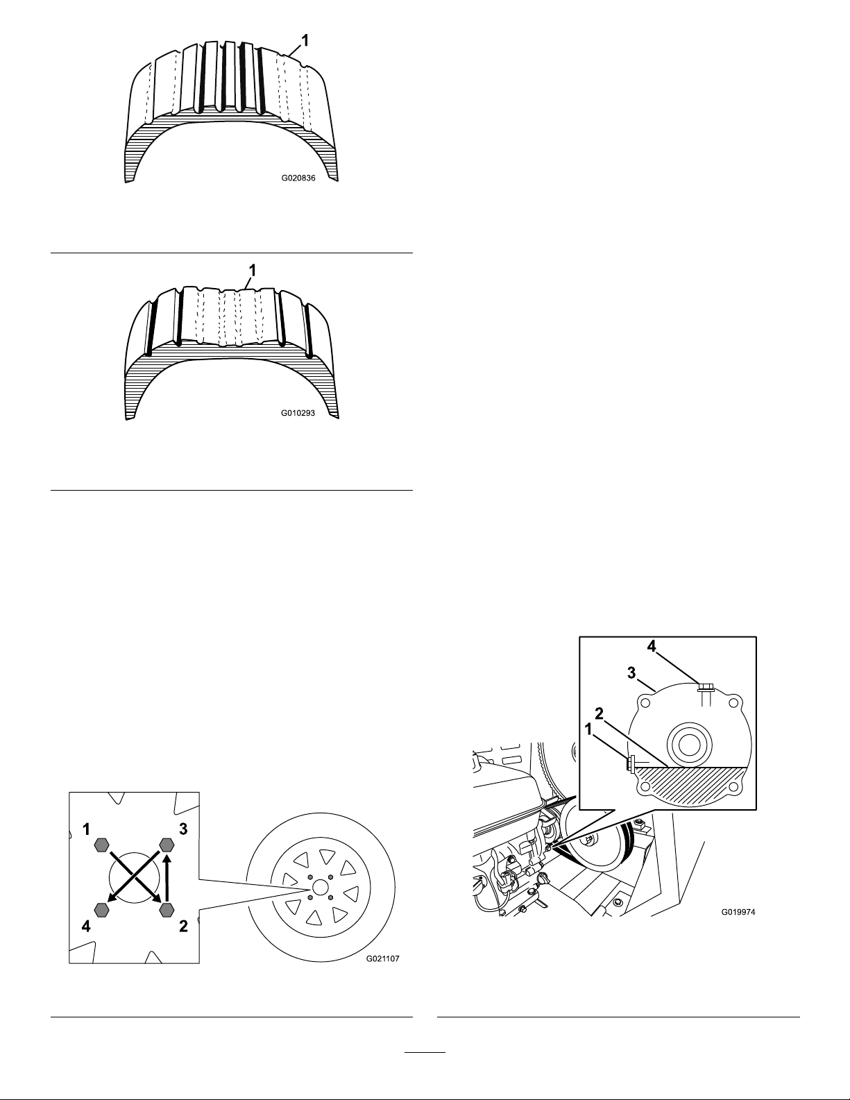
Figure59
1.Exampleoftirewearcausedbyunderination
Figure60
1.Exampleoftirewearcausedbyoverination
2.Ensurethatthetiresareinatedtothecorrect
airpressure;refertoTireAirPressure(page37).
Important:Themostcommoncauseoftire
troubleisunder-ination.Maintainfullair
pressure.
ServicingtheReduction Case
Models68013and68014Only
Important:Iftheoillevelinthereductioncase
istoolowortoohighandyouruntheengine,
youmaydamagetheengineorthereduction
g020836
g010293
case.Thistypeofdamageisnotcoveredbythe
warranty.
Reduction-CaseOilSpecications
Oiltype:4-cycle,SAE10W-30motoroil
OilAPIservicecategory:SJ,SL,SM,orhigher
Reduction-casecapacity:1.2L(40oz)
CheckingtheReduction-CaseOil
ServiceInterval:Beforeeachuseordaily—Check
thereduction-caseoil(Models
68013and68014only).
1.Parkthemachineonalevelsurfaceandshut
offtheengine.
2.Allowtheenginetocool.
3.Disconnectthewirefromthesparkplug;referto
DisconnectingtheSpark-PlugWire(page28).
4.Removethedividerplate;refertoRemovingthe
DividerPlate(page28).
5.Locatethereductioncasebetweentheengine
andtheenginepulley(Figure62).
TorquingtheWheelLug Nuts
ServiceInterval:Aftereachuse
Torquethewheellugnutsinitiallyandaftertowing.
Torquethewheellugnuts108to122N∙m(80to90
ft-lb),inthesequenceshowninFigure61.
Figure61
g019974
Figure62
g021107
1.Oil-level-checkboltand
washer
2.Oillevel(normal)
3.Reductioncase
4.Fillerboltandwasher
38
Page 39
6.Alignaragbelowtheoil-levelportintheside
ofthereductioncase.
7.Removetheoil-level-checkboltandwasher
fromtheoil-levelport(Figure62).
•Iftheoillevelisbelowthethreadsinthe
oil-levelport,addoilasfollows:
A.Removethellerboltandwasherfrom
thellerportonthetopofthereduction
case(Figure62).
B.Slowlypourthespeciedoilintothell
portuntiltheoillevelislevelwiththe
threadsatthebottomoftheoil-level
port.
C.Installthellerboltandthewasherto
thellerportofthereductioncase,and
tightenthellerbolt(Figure62).
•Iftheoillevelistoohigh,allowtheoiltoow
outuntilitisushwiththethreadsatthe
bottomoftheoil-levelport.
8.Whentheoilislevelisushwiththethreads
atthebottomoftheoil-levelport,installthe
oil-level-checkboltandwashertotheport,and
tightenthebolt(Figure62).
9.Installthedividerplate;refertoInstallingthe
DividerPlate(page28).
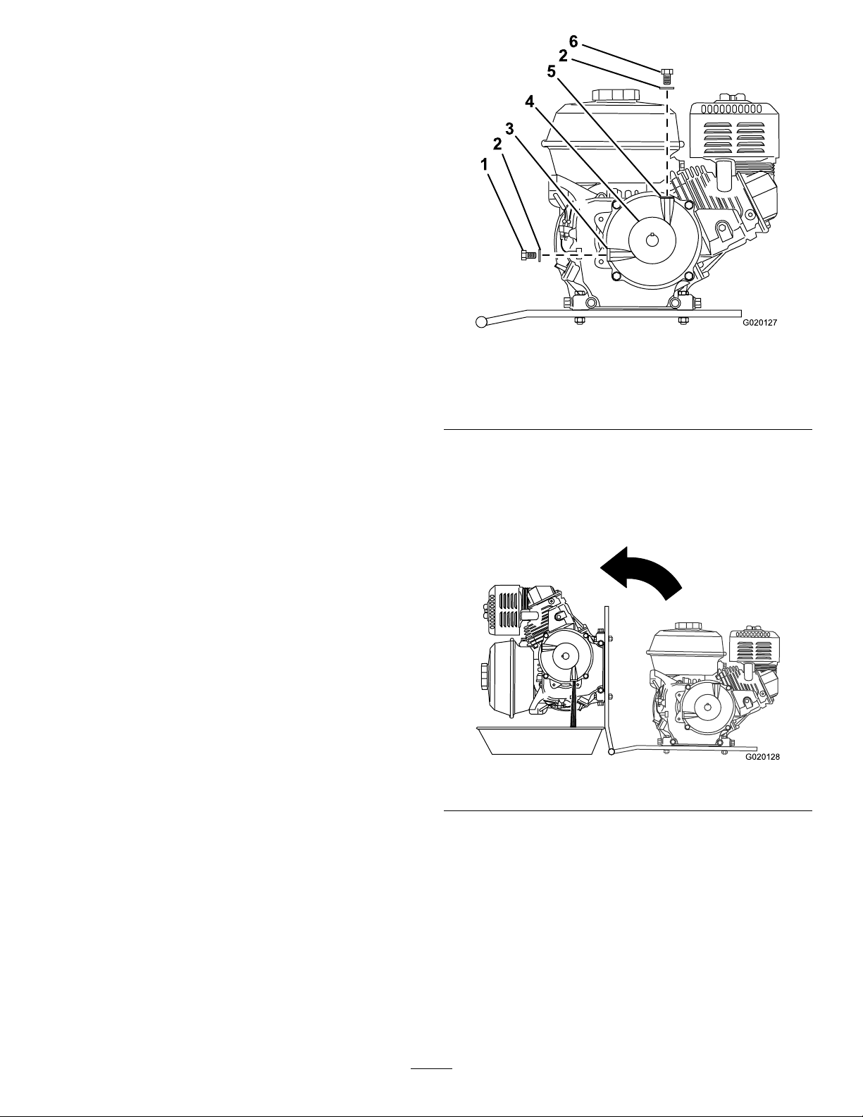
Figure63
1.Oil-level-check
bolt
2.Washer4.Pulley6.Fillerbolt
3.Oil-levelport
5.Fillerport
7.Removetheoil-level-checkboltandwasher
fromtheoil-levelportinthesideofthereduction
case(Figure63).
8.Alignadrainpantothehingeoftheenginedeck
(Figure64).
g020127
ChangingtheReduction-CaseOil
ServiceInterval:Aftertherst20hours—Changethe
reduction-caseoil(Models68013
and68014only).
Every100hours/Every6months(whichever
comesrst)—Changethereduction-caseoil
(Models68013and68014only).
1.Parkthemachineonalevelsurfaceandshut
offtheengine.
2.Allowtheenginetocool.
3.Disconnectthewirefromthesparkplug;referto
DisconnectingtheSpark-PlugWire(page28).
4.Removetheengine;refertoRemovingthe
Engine(page35).
5.Drainthefueltank;refertoDrainingtheFuel
Tank(page37).
6.Removethellerboltandwasherfromtheller
portonthetopofthereductioncase(Figure63).
g020128
Figure64
9.Rotatetheengineonthehingesideofthe
enginedeck,anddraintheoilfromthereduction
case(Figure64).
10.Carefullylowertheengineandenginedeck.
11.Slowlypourthespeciedoilintothellport
untiltheoillevelislevelwiththethreadsatthe
bottomoftheoil-levelport(Figure62).
12.Installtheoil-level-checkboltandwashertothe
oil-levelportofthereductioncase,andtighten
thebolt(Figure63).
39
Page 40
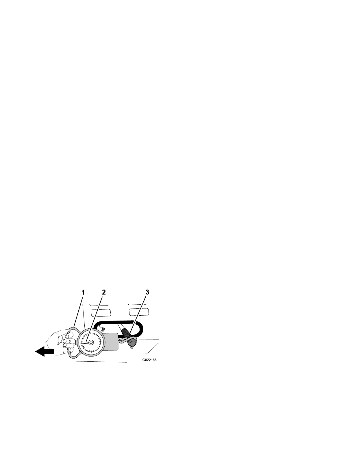
13.Installthellerboltandwashertothellerport
ofthereductioncaseandtightenthellerbolt
(Figure63).
14.Installtheengine;refertoInstallingtheEngine
(page36).
F.Observethespringscalewhilepullingto
seewhatthehighestpressureiswhen
movingtheclutchhandlefromtheOFF
positiontotheONposition(Figure65).
Note:Normalclutchpressureis15to30
kg(35to55lb).
ServicingtheGearbox
GearboxModelsOnly
CheckingtheClutchOperation
ServiceInterval:Beforeeachuseordaily(gearbox
modelonly).
Aftertherst25hours(gearboxmodelonly).
Important:Checkthegearboxclutchifthe
paddlesrotatewhentheclutchleverisintheOFF
position,ifthepaddlesrotateslowly,orifthe
clutchbeginstoslip.
1.MovetheclutchlevertotheOFFposition.
2.Starttheengine.
3.Ensurethattheenginethrottleissettothe2/3
position.
4.Ifthepaddlesrotatewiththeclutchlevertothe
OFFpositiondothefollowing:
A.Shutofftheengine.
B.Locatetheclutchleveratthebackofthe
machine;refertoClutchLever(page14).
C.MovetheclutchlevertotheOFFposition.
G.Iftheclutchpressureisgreaterthanor
lessthan15to30kg(35to55lb),contact
anAuthorizedToroServiceDealer.
Gearbox-OilSpecications
Oiltype:SAE90gearoil
Gearboxcapacity:2.13L(72oz)
CheckingtheGearboxOil
ServiceInterval:Every40hours(gearboxmodel
only).
Important:Iftheoillevelinthegearboxistoo
lowortoohighandyouruntheengine,youmay
damagetheengineorthegearbox.Thistypeof
damageisnotcoveredbythewarranty.
1.Parkthemachineonalevelsurfaceandshut
offtheengine.
2.Allowtheenginetocool.
3.Disconnectthewirefromthesparkplug;referto
DisconnectingtheSpark-PlugWire(page28).
4.Locatethegearboxbetweentheengineandthe
frontcowl.
D.Attachaspringscalewitharangeof15to
30kg(35to55lb)tothegripoftheclutch
lever(Figure65).
Figure65
1.Springscale3.Clutchlever
2.15to30kg(35to55lb)
E.Usingthespringscale,pulltheclutch
handletotheONpositionasshownin
Figure65.
5.Attherightsideofthegearbox,examinetheoil
levelinthesightglass(Figure66).
g022166
40
Page 41
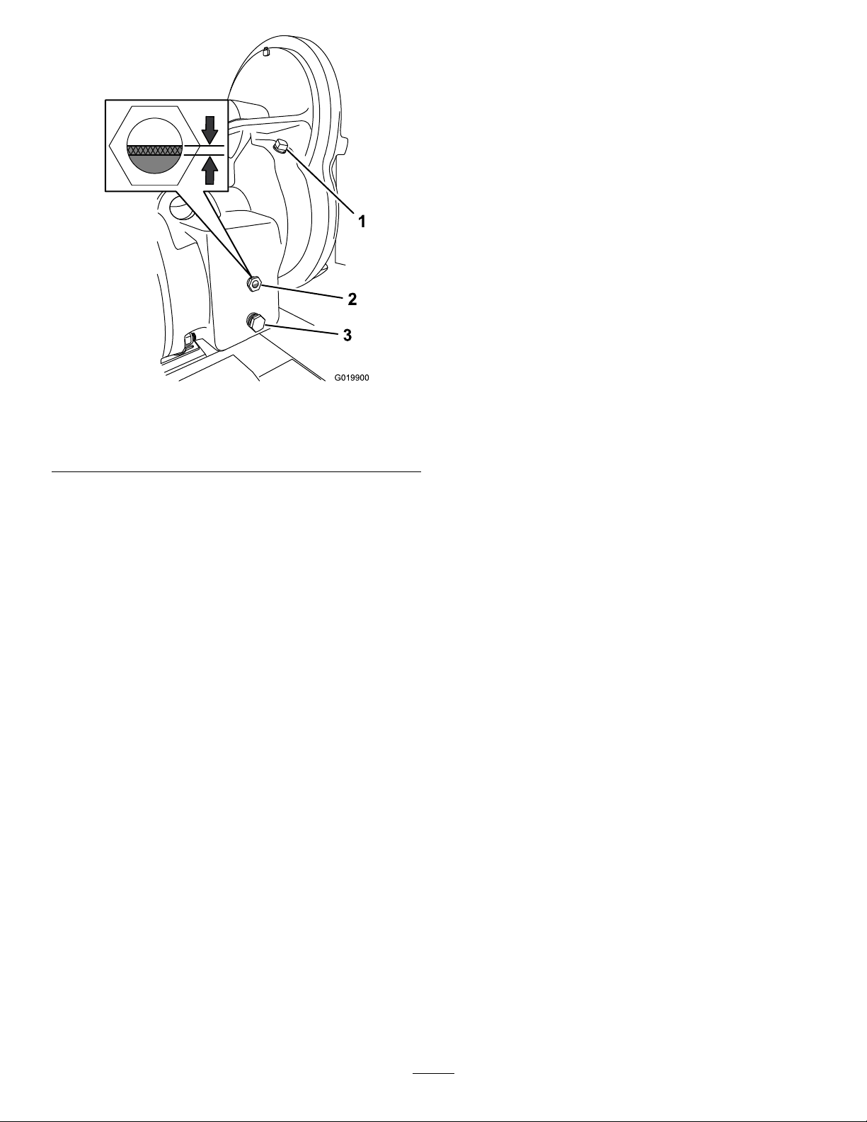
Figure66
1.Fillplug3.Drainplug
2.Sightglass
7.CleanthedrainandllplugsandapplyPTFE
thread-sealingtapetotheplugthreads.
8.Installthedrainpluginthedrainport(Figure66).
9.Slowlypourthespeciedoilintothellportuntil
theoillevelisbetween1/3and1/2ofthesight
glass(Figure66).
10.Installthellpluginthellport(Figure66).
g019900
6.Iftheoillevelisbelowthebottom1/3ofthesight
glass,addoilasfollows:
A.Removethellplugfromthellportinthe
housingofthegearbox(Figure66).
B.Slowlypourthespeciedoilintothellport
untiltheoillevelisbetween1/3and1/2of
thesightglass(Figure66).
C.Cleanthellplug.
D.ApplyPTFEthread-sealingtapetothe
threadsoftheplug.
E.Installtheplugintothellportinthehousing
(Figure66).
ReplacingtheGearboxOil
ServiceInterval:Every800hours(gearboxmodels
only).
1.Parkthemachineonalevelsurfaceandshut
offtheengine.
2.Allowtheenginetocool.
3.Disconnectthewirefromthesparkplug;referto
DisconnectingtheSpark-PlugWire(page28).
4.Alignadrainpanwitha2.8L(3USqt)capacity
underthedrainplug(Figure66).
5.Removethedrainplugfromthedrainportand
completelydrainthegearboxoil(Figure66).
6.Removethellplug(Figure66).
41
Page 42
BeltMaintenance
InspectingtheBelts
ServiceInterval:Aftertherst25hours—Inspect
thebeltsandadjustasnecessary
(belt-drivemodelsonly).
Every40hours—Inspectthebeltsandadjustas
necessary(belt-drivemodelsonly).
1.Parkthemachineonalevelsurfaceandshut
offtheengine.
2.Allowthemachinetocool.
3.Disconnectthewirefromthesparkplug;referto
DisconnectingtheSpark-PlugWire(page28).
4.Removethedividerplate;refertoRemovingthe
DividerPlate(page28).
5.MovetheclutchlevertotheOFFposition.
6.Examinethebeltsforwearordamage.Ifthe
beltsarewornordamaged,replacethem;refer
toReplacingtheBelts(page43).
7.Examinethepulleysforwear,damage,and
misalignment;refertoAligningthePulleys(page
45).
8.Installthedividerplate;refertoInstallingthe
DividerPlate(page28).
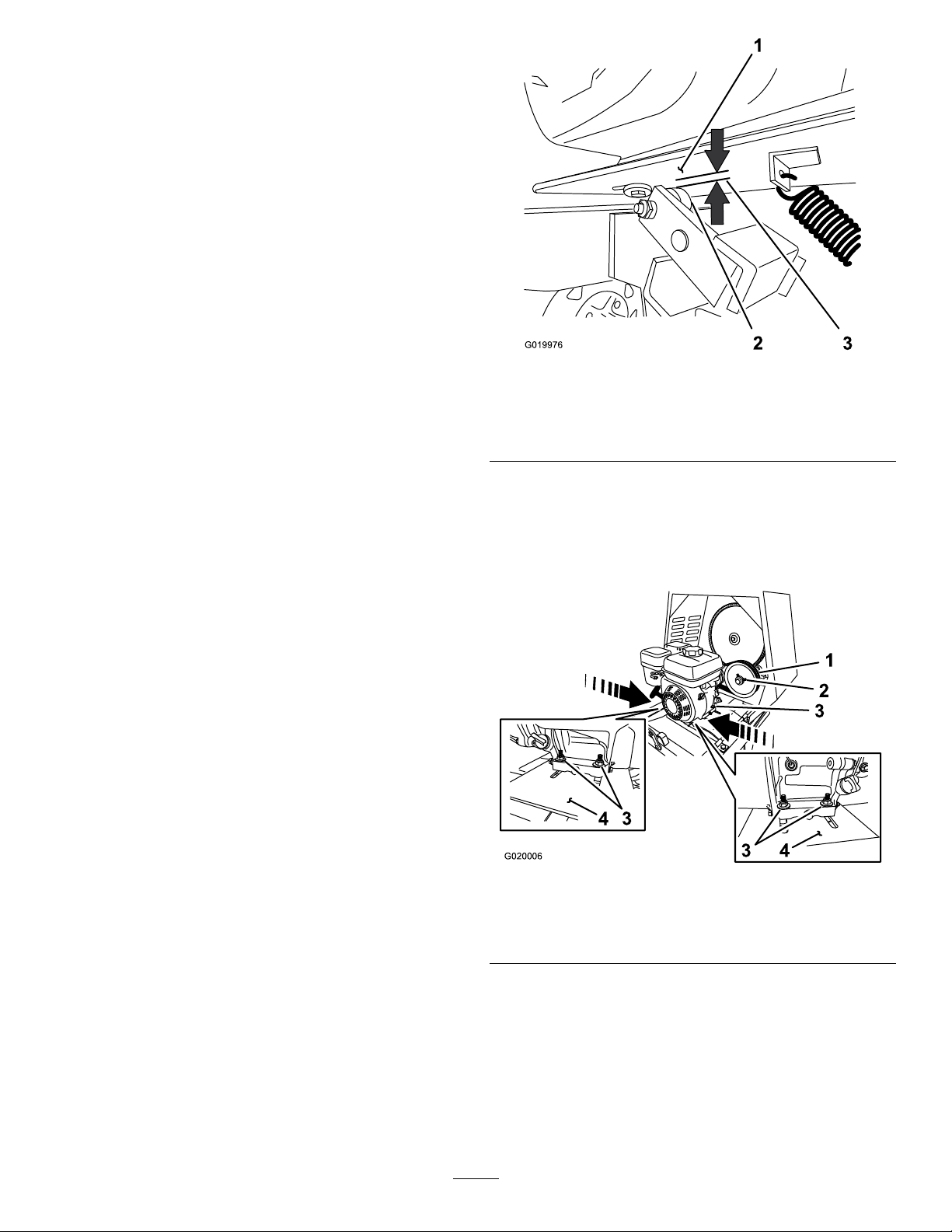
Figure67
1.Enginedeck
2.Clutchroller
6.Ifthemeasuredairgapisnotwithinthespecied
range,adjustthegapasfollows:
A.MovetheclutchlevertotheOFFposition.
B.Loosenthenutsandboltsthatsecurethe
enginetotheenginedeck(Figure68).
3.Clutchairgap:2.5to6.5
mm(3/32to1/4inch)
g019976
AdjustingtheBeltTension
Clutchairgap:2.5to6.5mm(3/32to1/4inch)
1.Parkthemachineonalevelsurfaceandshut
offtheengine.
2.Allowthemachinetocool.
3.Disconnectthewirefromthesparkplug;referto
DisconnectingtheSpark-PlugWire(page28).
4.MovetheclutchlevertotheONposition.
5.Measuretheairgapbetweentheenginedeck
andtherollerontheclutch(Figure67).
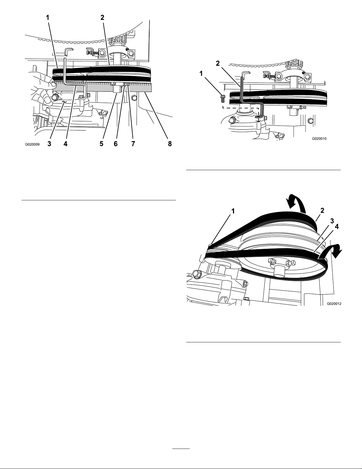
Figure68
1.Idlerpulley3.Nutandbolt
2.Setscrew
C.Movetheenginepositionasfollows:
4.Enginedeck
•Increasetheairgap—movetheengine
awayfromtheidlerpulley(Figure68).
•Decreasetheairgap—movethe
enginetowardtheidlerpulley(Figure
68).
D.Alignastraightedgeacrosstheengine
pulleyandtheidlerpulley(Figure69).
g020006
42
Page 43
5.Removethedividerplate;refertoRemovingthe
DividerPlate(page28).
6.Removetheboltthatsecuresthebeltguideto
theengine,andremovethebeltguide(Figure
70).
Figure69
1.Enginepulley
2.Idlerpulley6.Jamnut
3.Reductioncase(engine)7.Setscrew
4.Beltguide
5.Idlershaft
8.Straightedge
E.Ifnecessary ,pivottheengineontheengine
deckuntiltheenginepulleyandidlerpulley
arealignedtothestraightedge(Figure69).
F.Tightenthenutsandboltsthatsecurethe
enginetotheenginedecktoatorqueof18
N∙m(13ft-lb).
G.Checktheairgapbetweentheenginedeck
andtherollerontheclutch.Iftheairgapis
notwithinthespeciedrange,repeatstep6
untiltheairgapmeasurementiswithinthe
speciedrange.
H.Installthedividerplate;refertoInstalling
theDividerPlate(page28).
Important:Ensurethatthepaddlesdonotrotate
whentheclutchleverisintheOFFposition.
ReplacingtheBelts
ServiceInterval:Every2years(belt-drivemodels
only).
RemovingtheBelts
1.Parkthemachineonalevelsurfaceandshut
offtheengine.
2.Allowthemachinetocool.
3.Disconnectthewirefromthesparkplug;referto
DisconnectingtheSpark-PlugWire(page28).
4.MovetheclutchlevertotheOFFposition.
g020009
1.Bolt2.Beltguide
Figure70
g020010
7.Sliptheforwardbeltforwardandofftheidler
pulley(Figure71).
g020012
Figure71
1.Enginepulley3.Idlerpulley
2.Forwardbelt4.Rearbelt
8.Sliptherearbeltrearwardandofftheidlerpulley
(Figure71).
9.Slipthebeltsofftheenginepulley.
10.Removethebeltsfromthemachine.
InstallingtheBelts
1.Parkthemachineonalevelsurfaceandshut
offtheengine.
2.Allowthemachinetocool.
43
Page 44
3.Disconnectthewirefromthesparkplug;referto
DisconnectingtheSpark-PlugWire(page28).
4.EnsurethattheclutchleverisintheOFF
position.
5.Aligntherearbelttothereargrooveinthe
enginepulley.
Note:Donotaligntherearbelttotheidler
pulley.
6.Aligntheforwardbelttotheforwardgrooveof
theidlerpulley.
7.Sliptherearbeltovertheidlerpulleyandalign
thebelttotherearpulleygroove.
8.Sliptheforwardbeltovertheenginepulleyand
alignthebelttotheforwardpulleygroove.
9.Checkthebelttension;refertostep4through6
inAdjustingtheBeltT ension(page42).
10.Looselysecurethebeltguidetotheengine
(Figure70)withtheboltthatwasremovedin
step6ofRemovingtheBelts(page43).
11.Adjustthebeltguide;refertoAdjustingtheBelt
Guide(page44).
12.Installthedividerplate;refertoInstallingthe
DividerPlate(page28).
AdjustingtheBeltGuide
Note:T oaccessthebeltguide,removethedivider
plate;refertoRemovingtheDividerPlate(page28).
Guideairgap:2.5to4.0mm(3/32to5/32inch)
1.Parkthemachineonalevelsurfaceandshut
offtheengine.
2.Allowthemachinetocool.
3.Disconnectthewirefromthesparkplug;referto
DisconnectingtheSpark-PlugWire(page28).
4.EnsurethattheclutchleverisintheONposition.
5.Ensurethatthebelttensioniscorrect;referto
AdjustingtheBeltTension(page42).
6.Checkthattheairgapbetweenthebeltguide
andthebeltsis2.5to4.0mm(3/32to5/32
inch);refertoFigure72.
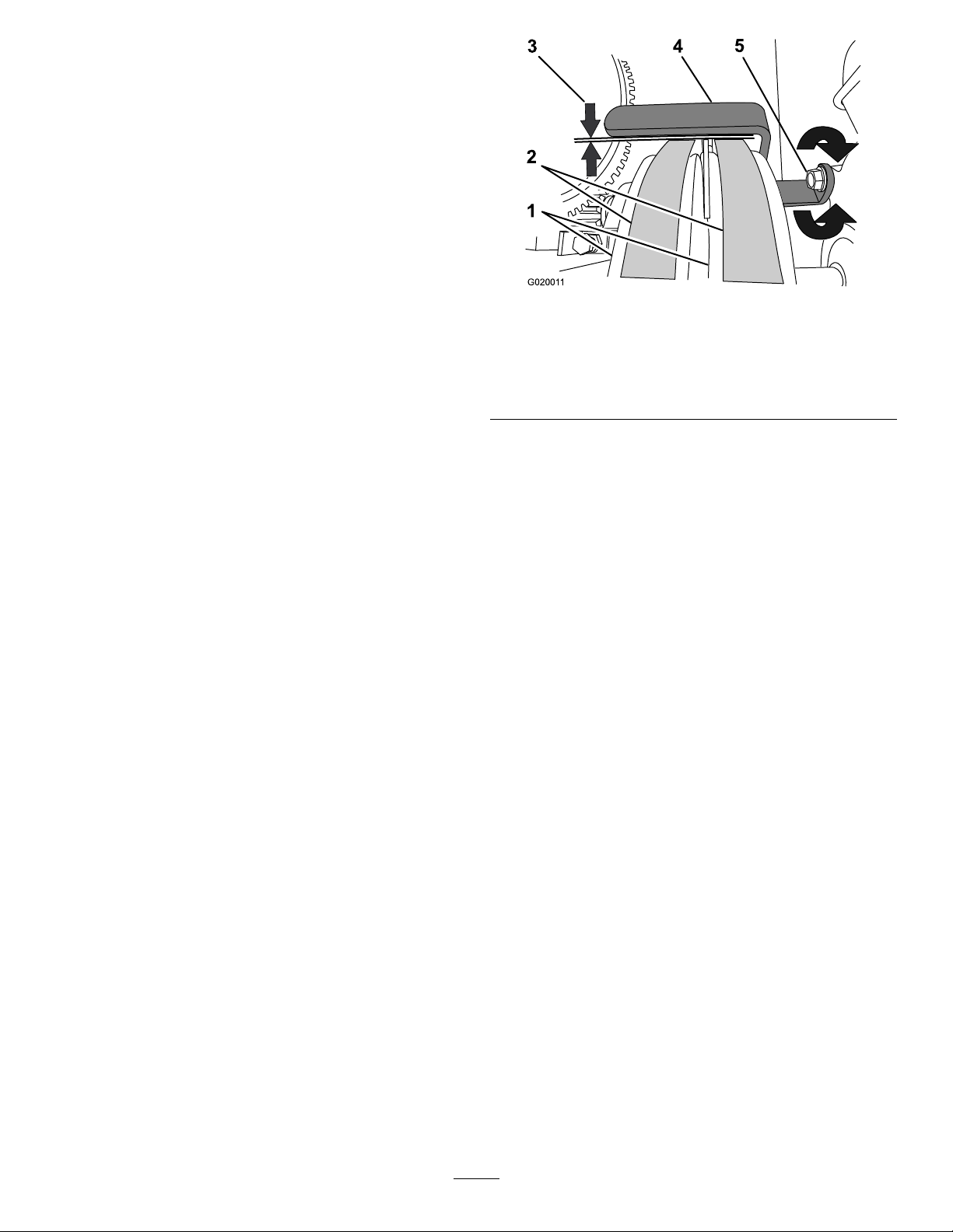
g020011
Figure72
1.Enginepulleys4.Beltguide
2.Belts5.Bolt
3.Guideairgap:2.5to4.0
mm(3/32to5/32inch)
7.Iftheairgapisnotwithinthespeciedrange,
dothefollowing:
A.Loosentheboltthatsecuresthebeltguide
totheengine(Figure72).
Important:Ensurethatthebeltguideis
towardtheenginepulley.
B.Rotatethebeltguideupordownuntilthere
isanairgapof2.5to4.0mm(3/32to5/32
inch)betweentheguideandeachbelt
(Figure72).
Important:Thebeltguideshouldnot
contactthebeltswiththeclutchleverin
theONposition.
Note:Iftheairgapbetweenthebeltguide
andbothbeltscannotbeattained,then1of
thebeltsistoolong.
C.Tightentheboltthatsecuresthebeltguide
totheengine(Figure72).
D.Checktheclutchoperation;referto
CheckingtheClutchOperation(page44).
8.Installthedividerplate;refertoInstallingthe
DividerPlate(page28).
CheckingtheClutchOperation
ServiceInterval:Every40hours
Important:Thepaddlesmustnotrotateinan
emptydrumwhentheclutchleverisintheOFF
position.
1.MovetheclutchlevertotheOFFposition.
2.Starttheengine.
3.Ifthepaddlesrotatewiththeclutchlevertothe
OFFpositiondothefollowing:
44
Page 45
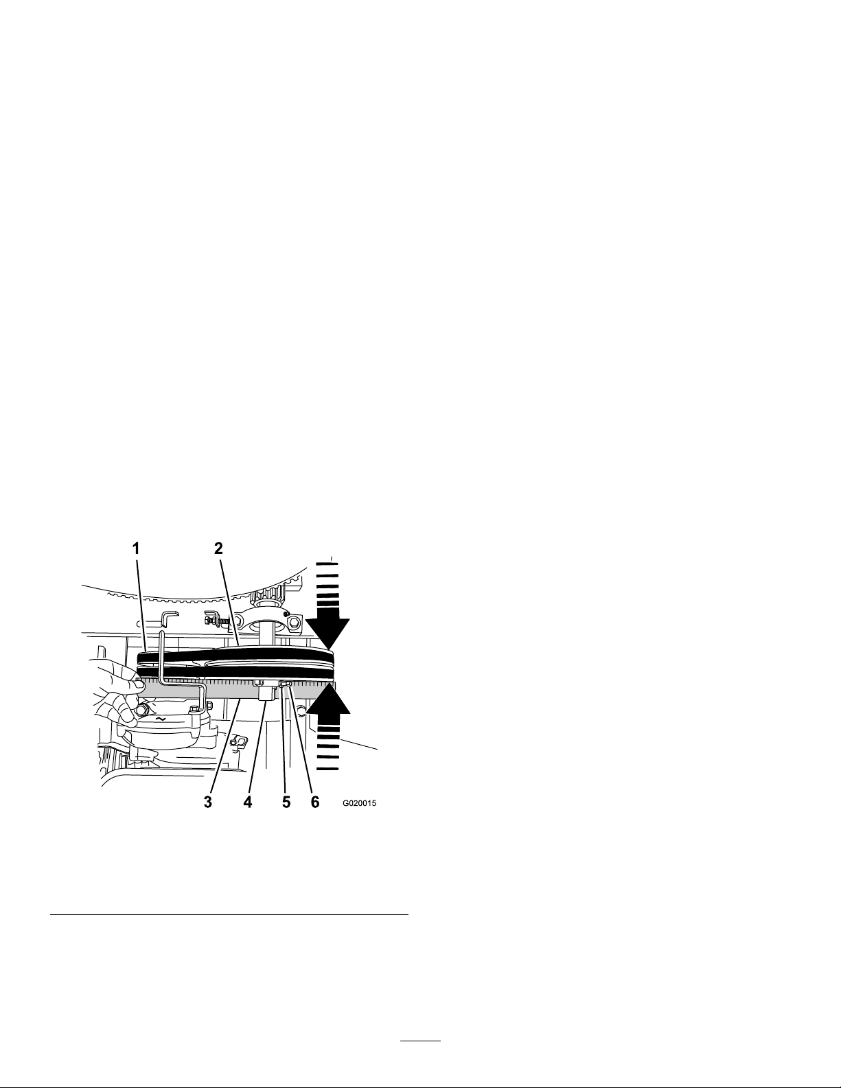
A.Shutofftheengine.
B.Checktheairgapbetweenthebeltguide
andthebelts.
Note:Iftheairgapislargerthan4.0mm
(5/32inch),decreasethegapbetweenthe
beltguideandthebelts;refertoAdjusting
theBeltGuide(page44).
4.Repeatsteps1through3untilallthefollowing
conditionsaremet:
•Theengineisrunat2/3throttle.
•TheclutchleverisintheOFFposition.
•Thepaddlesdonotrotateinanemptydrum
whiletheengineisrunning.
AligningthePulleys
1.Parkthemachineonalevelsurfaceandshut
offtheengine.
2.Allowthemachinetocool.
3.Disconnectthewirefromthesparkplug;referto
DisconnectingtheSpark-PlugWire(page28).
B.Loosenthelocknutsandsetscrewsthat
securetheidlerpulleytotheidlershaft
(Figure73).
C.Usingasoft-facemallet,taptheidlerpulley
forwardorbackwardalongtheidlershaft
untiltheenginepulleyandidlerpulleyare
alignedtothestraightedge(Figure73).
D.Tightenthesetscrewsandlocknutsthat
securetheidlerpulleytotheidlershaft
(Figure73).
7.Installthedividerplate;refertoInstallingthe
DividerPlate(page28).
4.Removethedividerplate;refertoRemovingthe
DividerPlate(page28).
5.Placeastraightedgeacrossthefaceofthe
enginepulleyandidlerpulley(Figure73).
Figure73
1.Enginepulley
2.Idlerpulley5.Locknut
3.Straightedge6.Setscrew
4.Idlershaft
g020015
Note:Bothpulleysmustbealignedushwith
thestraightedge.
6.Ifthepulleysarenotaligneddothefollowing:
A.MovetheclutchlevertotheOFFposition.
45
Page 46
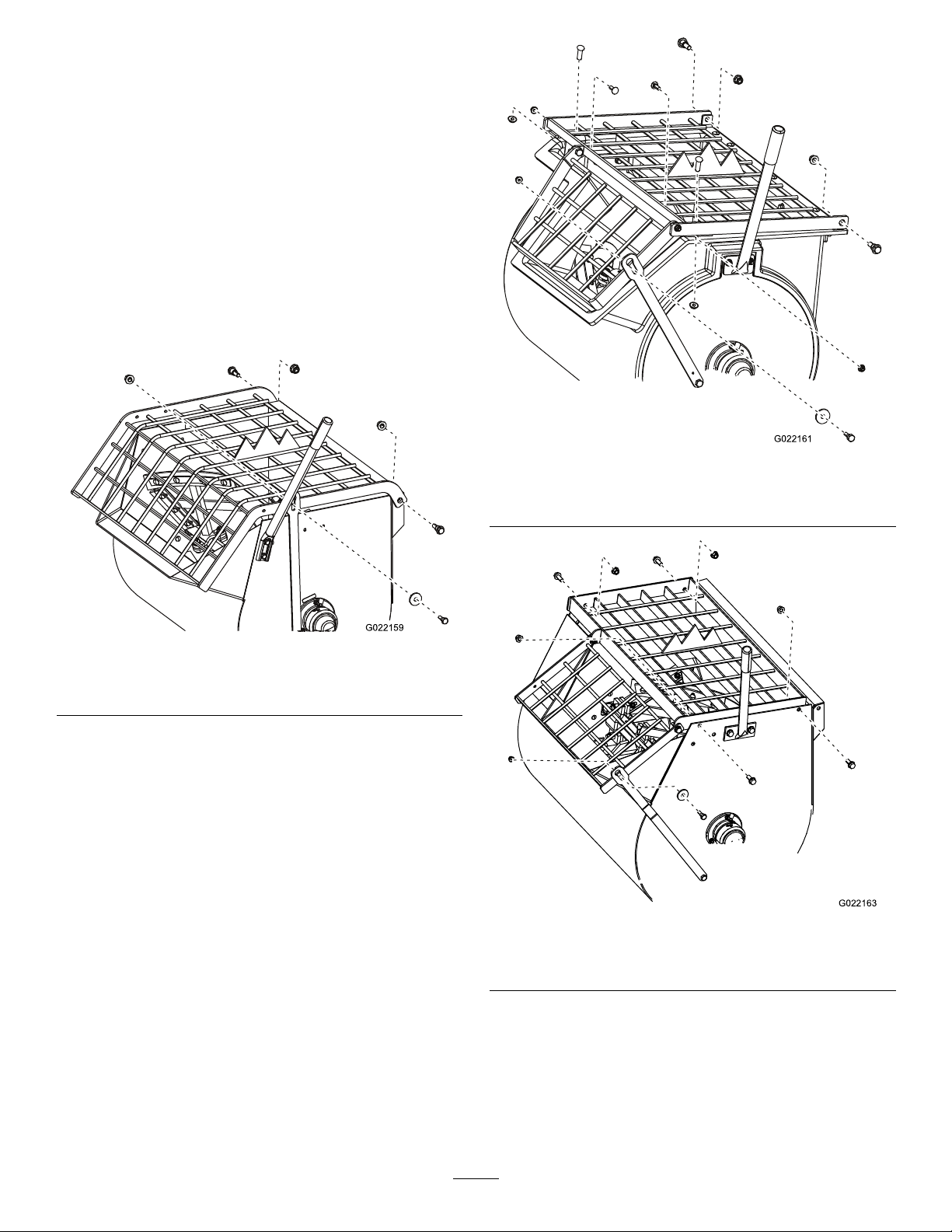
PaddleMaintenance
AdjustingthePaddle Blades
1.Parkthemachineonalevelsurfaceandshut
offtheengine.
2.Allowtheenginetocool.
3.Disconnectthewirefromthesparkplug;referto
DisconnectingtheSpark-PlugWire(page28).
4.Removethenutsandboltsthatsecurethegrate
tothedrum,andremovethegrate(Figure74,
Figure75,orFigure76).
g022161
Figure75
Models68014,68017,68021
Figure74
Models68013,68016,68020
g022159
g022163
Figure76
Model68024
46
Page 47
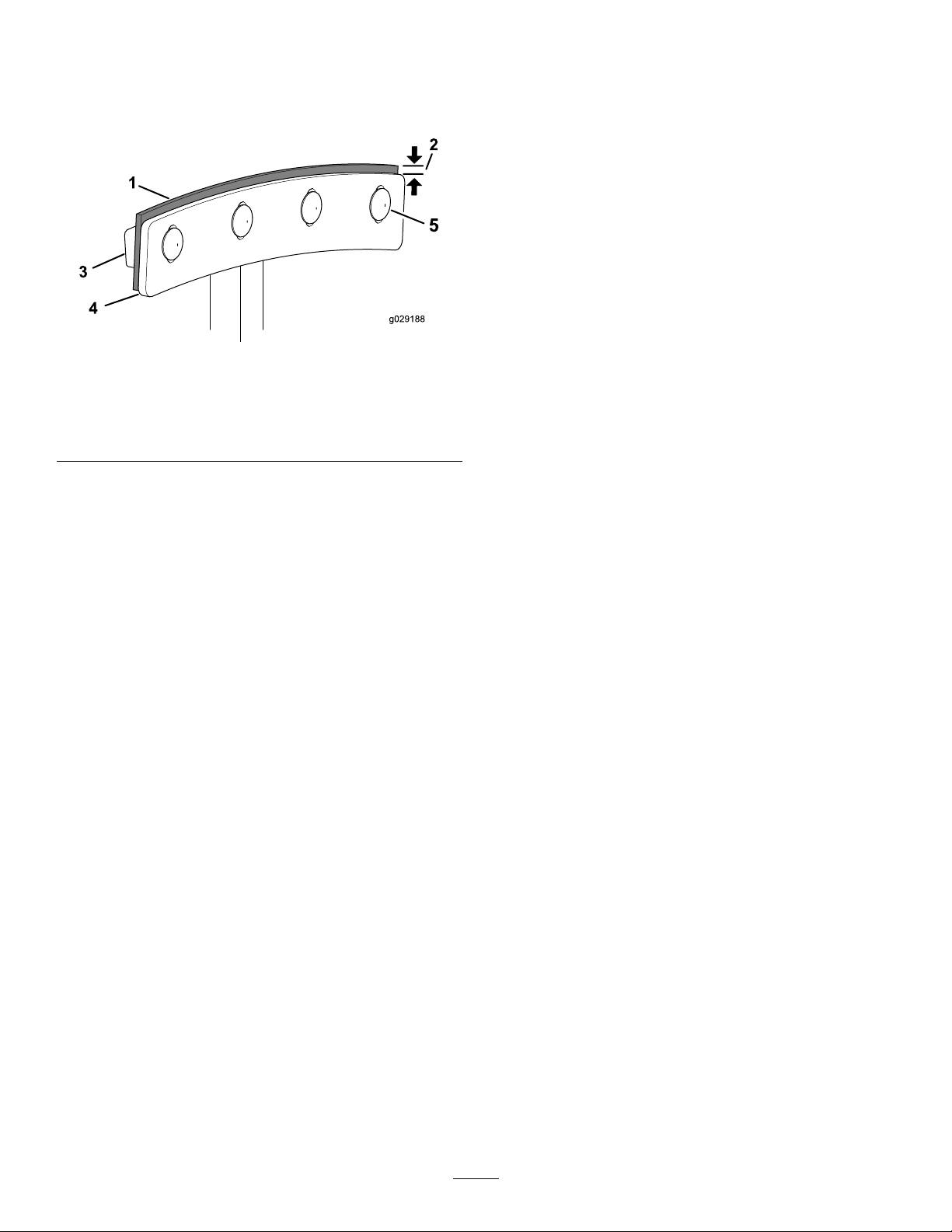
5.Loosenthecarriageboltsandnutsthatsecure
thewiperstothepaddlebladess(Figure77).
Note:Ifnecessary,tipthedrumtothedump
positiontoaccessthepaddles.
Cleaning
CleaningtheMachine
Regularcleaningandwashingwithmilddetergentand
waterincreasesthelifespanofthemachine.Clean
themachineaftereachusebeforethedirthardens.
Removedirtandgrimefromtheexternalpartsofthe
entiremachine,especiallytheengine.Cleandirtand
concretematerialsfromtheoutsideoftheengine.
Ensurethatthefuelcapandtheoil-llcap/dipstickare
securetoavoidgettingwaterintheengine.
Figure77
1.Wiper4.Paddleblade
2.3to6mm(1/8to1/4inch)5.Carriagebolt
3.Wiperbar
6.Adjusttherubberwiperstobeclosetothedrum
wallandpositionthemetalpaddlebladesso
thattheouteredgeis3to6mm(1/8to1/4inch)
fromtheouteredgeofthewipers(Figure77).
Tightenthenutsandboltstosecuretheblades
tothepaddles.
Note:EnsurethattheclutchleverisintheOFF
positionandrotatethepaddlesasneeded.
7.Installthegratewiththenutsandboltsthatyou
removedinstep4,andtightenthenutsand
boltsuntiltheyaresecure.
g029188
Usecarewhenusingahigh-pressuresprayer
becauseitcandamagethesafetydecals,instruction
signs,andtheengine.
Important:Lubricatethebearingsandsealsafter
cleaning;refertoLubricatingtheBearingsand
Seals(page29).
47
Page 48

Storage
plug.
Note:Donotinstallthewireonthespark
Forstorageover30days,preparethemachineas
follows:
1.Removedirtandgrimefromtheexternalpartsof
theentiremachine,especiallytheengine.Clean
dirtanddebrisfromtheoutsideoftheengine
cylinder-headnsandblowerhousing.
Important:Youcanwashthemachinewith
milddetergentandwater.
2.Conditionthefuelsystemasfollows:
A.Addapetroleum-based
stabilizer/conditionertofuelinthe
tank.Followthemixinginstructionsfrom
thestabilizermanufacturer.Donotuse
analcohol-basedstabilizer(ethanolor
methanol).
Important:Donotstore
stabilizer/conditionedfuelover90
days.
Note:Fuelstabilizer/conditionerismost
effectivewhenmixedwithfreshfueland
usedatalltimes.
B.Runtheenginefor5minutestodistribute
theconditionedfuelthroughthefuelsystem.
C.Shutofftheengine,allowittocool,and
drainthefueltankusingapump-type
siphon.Disposeoffuelproperly;recycleit
accordingtolocalcodes.
D.Starttheengineandrunituntilitstops.
E.Choketheengine.
F.Startandruntheengineuntilitdoesnot
startagain.
3.Cleanthesedimentcup;refertoCleaningthe
Fuel-SedimentCup(page36).
4.Servicetheaircleaner;refertoServicingtheAir
Cleaner(page30).
5.Changetheengineoil;refertoChangingthe
EngineOil(page31).
6.Removethesparkplugandcheckthecondition;
refertoServicingtheSparkPlug(page33).
7.Conditiontheengineasfollows:
A.Pour2tablespoonsofengineoilintothe
spark-plughole;refertoRemovingthe
SparkPlug(page33).
B.Pulltherecoil-starthandleslowlytocrank
theengineanddistributetheoilinsidethe
cylinder.
C.Installthesparkplug;refertoInstallingthe
SparkPlug(page34).
8.Greasethemachine;refertoLubricatingthe
BearingsandSeals(page29).
9.Checkandtightenallbolts,nuts,andscrews.
Repairorreplaceanypartthatisdamaged.
10.Paintallscratchedorbaremetalsurfaceswith
paintavailablefromyourAuthorizedService
Dealer.
11.Storethemachineinaclean,drygarageor
storagearea.
12.Coverthemachinetoprotectitandkeepitclean.
48
Page 49

Troubleshooting
Problem
Theenginedoesnotstart.
Theenginelackspowerorrunsrough.
PossibleCauseCorrectiveAction
1.Thefuel-valveleverisintheOFF
position.
2.Thechokeisclosed
3.Thechokeisopen.
4.TheengineOn/OffswitchisintheOFF
position.
5.Theengineoillevelislow(engines
withtheoil-levelswitch).
6.Thefueltankisempty.6.Fillthefueltankwithfreshfuel.
7.Theenginecontainsbad/oldfuel.7.Drainthefueltankandcarburetor.
8.Thesparkplugisfouledorimproperly
gapped.
9.Thesparkplugiswetwithfuel(ooded
engine).
10.Thespark-plugwireislooseor
disconnected.
1.Theairlterisrestricted.
2.Theenginecontainsbadoroldfuel.
3.Thereiswaterorcontaminationinthe
fuel.
4.Thefuellineisrestricted.4.Cleanthefuellterandsedimentcup.
5.Thechokeisclosed
6.Thesparkplugiswornorhasbuildup
ontheelectrodes.
7.Thereistoomuchoilintheengine
crankcase.
1.Movethefuel-valvelevertotheON
position.
2.Openthechokewhenstartingahot
engine.
3.Closethechokewhenstartingacold
engine.
4.RotatetheswitchtotheONposition.
5.Filltheengine,withtherecommended
oil,totheproperlevel.
Refuelwithfreshfuel.
8.Gaporreplacethesparkplug.
9.Removethesparkplug,dryit,and
installtheplug.Starttheenginewith
thethrottleintheMAXposition.
10.Removethespark-plugwire,cleanthe
spark-plugterminalandtheterminal
socketinthebootofthespark-plug
wire,andinstallthespark-plugwire.
1.Cleanorreplacetheair-lter
element(s).
2.Drainthefueltankandcarburetor.
Refuelwithfreshfuel.
3.Drainthefueltankandcarburetor.
Refuelwithfreshfuel.
5.Openthechoke.
6.Checktheelectrodegapandadjustor
replacethesparkplug.
7.Draintheoiltotheproperlevel.
Thebeltssliporcomeoffthepulleys
(belt-drivemodelsonly).
isintheOFFposition(belt-drivemodels
only).
Thepaddlesrotatewhentheclutchleveris
intheOFFposition(gearboxmodelonly).
leverisintheONposition(belt-drive
modelsonly).
Thepaddlesdonotrotatewhentheclutch
leverisintheONposition(gearboxmodel
only).
1.Thebelttensionisinsufcient.
2.Thebeltsareworn.2.Replacethebelts.
3.Thepulley(s)areworn.
4.Thepulley(s)aremisaligned.4.Alignthepulley(s).
1.Theclutchleverisnotadjusted
correctly.
2.Thebeltguideisnotadjustedcorrectly .2.Adjustthebeltguide.
1.Theclutchisnotadjustedcorrectly.
1.Theclutchleverisnotadjusted
correctly.
2.Thepaddlesarestuckinthedrum
1.Theclutchisnotadjustedcorrectly.
1.Adjustthebelttension.
3.ContactyourAuthorizedService
Dealer.
1.Adjustthebelttension. Thepaddlesrotatewhentheclutchlever
1.ContactyourAuthorizedService
Dealer.
1.Adjustthebelttension. Thepaddlesdonotrotatewhentheclutch
2.Cleanthepaddlesanddrum.
1.ContactyourAuthorizedService
Dealer.
49
Page 50

Problem
PossibleCauseCorrectiveAction
Thepaddlesrotateslowlywhentheclutch
leverisintheONposition(belt-drive
modelsonly).
Thepaddlesrotateslowlywhentheclutch
leverisintheONposition(gearboxmodel
only).
1.Theclutchleverisnotadjusted
correctly.
1.Theclutchisnotadjustedcorrectly.
1.Adjustthebelttension.
1.ContactyourAuthorizedService
Dealer.
50
Page 51

CaliforniaProposition65WarningInformation
Whatisthiswarning?
Youmayseeaproductforsalethathasawarninglabellikethefollowing:
WARNING:CancerandReproductiveHarm—www.p65Warnings.ca.gov.
WhatisProp65?
Prop65appliestoanycompanyoperatinginCalifornia,sellingproductsinCalifornia,ormanufacturingproductsthatmaybesoldinorbroughtinto
California.ItmandatesthattheGovernorofCaliforniamaintainandpublishalistofchemicalsknowntocausecancer,birthdefects,and/orother
reproductiveharm.Thelist,whichisupdatedannually,includeshundredsofchemicalsfoundinmanyeverydayitems.ThepurposeofProp65isto
informthepublicaboutexposuretothesechemicals.
Prop65doesnotbanthesaleofproductscontainingthesechemicalsbutinsteadrequireswarningsonanyproduct,productpackaging,orliteraturewith
theproduct.Moreover,aProp65warningdoesnotmeanthataproductisinviolationofanyproductsafetystandardsorrequirements.Infact,the
CaliforniagovernmenthasclariedthataProp65warning“isnotthesameasaregulatorydecisionthataproductis‘safe’or‘unsafe.’”Manyofthese
chemicalshavebeenusedineverydayproductsforyearswithoutdocumentedharm.Formoreinformation,gotohttps://oag.ca.gov/prop65/faqs-view-all
AProp65warningmeansthatacompanyhaseither(1)evaluatedtheexposureandhasconcludedthatitexceedsthe“nosignicantrisklevel”;or(2)
haschosentoprovideawarningbasedonitsunderstandingaboutthepresenceofalistedchemicalwithoutattemptingtoevaluatetheexposure.
Doesthislawapplyeverywhere?
Prop65warningsarerequiredunderCalifornialawonly.ThesewarningsareseenthroughoutCaliforniainawiderangeofsettings,includingbutnot
limitedtorestaurants,grocerystores,hotels,schools,andhospitals,andonawidevarietyofproducts.Additionally,someonlineandmailorder
retailersprovideProp65warningsontheirwebsitesorincatalogs.
.
HowdotheCaliforniawarningscomparetofederallimits?
Prop65standardsareoftenmorestringentthanfederalandinternationalstandards.TherearevarioussubstancesthatrequireaProp65warning
atlevelsthatarefarlowerthanfederalactionlimits.Forexample,theProp65standardforwarningsforleadis0.5μg/day,whichiswellbelow
thefederalandinternationalstandards.
Whydon’tallsimilarproductscarrythewarning?
•ProductssoldinCaliforniarequireProp65labellingwhilesimilarproductssoldelsewheredonot.
•AcompanyinvolvedinaProp65lawsuitreachingasettlementmayberequiredtouseProp65warningsforitsproducts,butothercompanies
makingsimilarproductsmayhavenosuchrequirement.
•TheenforcementofProp65isinconsistent.
•CompaniesmayelectnottoprovidewarningsbecausetheyconcludethattheyarenotrequiredtodosounderProp65;alackofwarningsfora
productdoesnotmeanthattheproductisfreeoflistedchemicalsatsimilarlevels.
WhydoesToroincludethiswarning?
Torohaschosentoprovideconsumerswithasmuchinformationaspossiblesothattheycanmakeinformeddecisionsabouttheproductstheybuyand
use.T oroprovideswarningsincertaincasesbasedonitsknowledgeofthepresenceofoneormorelistedchemicalswithoutevaluatingthelevelof
exposure,asnotallthelistedchemicalsprovideexposurelimitrequirements.WhiletheexposurefromT oroproductsmaybenegligibleorwellwithinthe
“nosignicantrisk”range,outofanabundanceofcaution,T orohaselectedtoprovidetheProp65warnings.Moreover,ifT orodoesnotprovidethese
warnings,itcouldbesuedbytheStateofCaliforniaorbyprivatepartiesseekingtoenforceProp65andsubjecttosubstantialpenalties.
RevA
Page 52

Alimitedwarranty(seewarrantyperiodsbelow)
TheToroWarranty
Concrete,
Masonry,and
Compaction
Equipment
ConditionsandProductsCovered
TheT oroCompanyanditsafliate,T oroWarrantyCompany ,pursuantto
anagreementbetweenthem,jointlywarrantyourT oroConcrete,Masonry,
andCompactionEquipmentProductslistedbelowtobefreefromdefectsin
materialsorworkmanship.
Thiswarrantycoversthecostofpartsandlabor,butyoumustpay
transportationcosts.
Thefollowingtimeperiodsapplyfromthedateofpurchase:
ProductsWarrantyPeriod
ConcreteMixers
•SpindleBearingsLifetime*(originalowneronly)
MortarMixers1year
•DrumBearingsandSealsLifetime*(originalowneronly)
ForwardPlateCompactors
ReversiblePlates1year
RammerCompactors
MudBuggy1year
VibratingTrenchRoller2years
ConcreteSaws
MasonrySaws
PowerTrowels1year
Screeds
ConcreteVibrators
Whereawarrantableconditionexists,wewillrepairtheProductatnocost
toyouincludingdiagnosis,labor,andparts.
*
LifetimeWarranty-Ifthebearing(s)orseal(s)onyourmixerfail,itwillbereplacedunderwarranty ,
atnocostforpartsorlabor.
1year
2years
2years
1year
1year
1year
1year
InstructionsforObtainingWarrantyService
IfyouthinkthatyourT oroProductcontainsadefectinmaterialsor
workmanship,followthisprocedure
1.ContactanyAuthorizedServicingOutlettoarrangeserviceattheir
dealership.T olocateoneconvenienttoyou,accessourwebsiteat
www.T oro.com.Select“WheretoBuy”andselect“Contractor”under
producttype.Y oumayalsocallourtollfreenumberbelow.
2.Bringtheproductandyourproofofpurchase(salesreceipt)tothem.
3.IfforanyreasonyouaredissatisedwiththeServiceOutlet’sanalysis
orwiththeassistanceprovided,contactusat:
SWSCustomerCareDepartment
ToroWarrantyCompany
811 1LyndaleAvenueSouth
Bloomington,MN55420-1196
TollFree:800-888-9926
**
ToroAuthorizedRentalCustomerswhohavepurchasedproductsdirectlyfromT oroandhave
signedtheT oroRentalCustomerAgreementhavetheabilitytoperformtheirownwarrantywork.
PleasevisitT oro’sRentalPortalforelectronicwarrantyclamlingproceduresorcallthetollfree
numberabove.
**
:
OwnerResponsibilities
YoumustmaintainyourT oroProductbyfollowingthemaintenance
proceduresdescribedintheOperator’sManual.Suchroutinemaintenance,
whetherperformedbyadealerorbyyou,isatyourexpense.Parts
scheduledforreplacementasrequiredmaintenance(“MaintenanceParts”),
arewarrantedfortheperiodoftimeuptothescheduledreplacementtime
forthatpart.Failuretoperformrequiredmaintenanceandadjustmentscan
begroundsfordisallowingawarrantyclaim.
ItemsandConditionsNotCovered
Notallproductfailuresormalfunctionsthatoccurduringthewarrantyperiod
aredefectsinmaterialsorworkmanship.Thisexpresswarrantydoesnot
coverthefollowing:
•Productfailureswhichresultfromtheuseofnon-T ororeplacement
parts,orfrominstallationanduseofadd-on,modied,orunapproved
accessories
•Productfailureswhichresultfromfailuretoperformrequired
maintenanceand/oradjustments
•ProductfailureswhichresultfromoperatingtheProductinanabusive,
negligentorrecklessmanner
•Partssubjecttoconsumptionthroughuseunlessfoundtobedefective.
Examplesofpartswhichareconsumed,orusedup,duringnormal
productoperationinclude,butarenotlimitedto,belts,wipers,spark
plugs,tires,lters,gaskets,wearplates,seals,O-rings,drivechains,
clutches.
•Failurescausedbyoutsideinuence.Itemsconsideredtobeoutside
inuenceinclude,butarenotlimitedto,weather,storagepractices,
contamination,useofunapprovedcoolants,lubricants,additives,or
chemicals,etc.
•Normal“wearandtear”items.Normal“wearandtear”includes,butis
notlimitedto,wornpaintedsurfaces,scratcheddecals,etc.
•Repairsnecessaryduetofailuretofollowrecommendedfuel
procedure(consultOperator'sManualformoredetails)
–Removingcontaminantsfromthefuelsystemisnotcovered
–Useofoldfuel(morethanonemonthold)orfuelwhichcontains
morethan10%ethanolormorethat15%MTBE
–Failuretodrainthefuelsystempriortoanyperiodofnon-use
overonemonth
•Anycomponentcoveredbyaseparatemanufacturer’swarranty
•Pickupanddeliverycharges
GeneralConditions
RepairbyanAuthorizedServicingOutletorSelf-ServiceasanAuthorized
RentalCustomerisyoursoleremedyunderthewarranty.
NeitherTheToroCompanynorToroWarrantyCompanyisliablefor
indirect,incidentalorconsequentialdamagesinconnectionwiththe
useoftheToroProductscoveredbythiswarranty,includingany
costorexpenseofprovidingsubstituteequipmentorserviceduring
reasonableperiodsofmalfunctionornon-usependingcompletionof
repairsunderthiswarranty .Allimpliedwarrantiesofmerchantability
andtnessforusearelimitedtothedurationofthisexpresswarranty.
Somestatesdonotallowexclusionsofincidentalorconsequential
damages,orlimitationsonhowlonganimpliedwarrantylasts,sothe
aboveexclusionsandlimitationsmaynotapplytoyou.
Thiswarrantygivesyouspeciclegalrights,andyoumayalsohaveother
rightswhichvaryfromstatetostate.
ExceptfortheenginewarrantycoverageandtheEmissionswarranty
referencedbelow,ifapplicable,thereisnootherexpresswarranty .The
EmissionsControlSystemonyourProductmaybecoveredbyaseparate
warrantymeetingrequirementsestablishedbytheU.S.Environmental
ProtectionAgency(EPA)ortheCaliforniaAirResourcesBoard(CARB).
RefertotheCaliforniaEmissionControlWarrantyStatementsuppliedwith
yourProductorcontainedintheenginemanufacturer’sdocumentationfor
details.
CountriesOtherthantheUnitedStatesorCanada
CustomerswhohavepurchasedT oroproductsoutsidetheUnitedStatesorCanadashouldcontacttheirT oroDistributor(Dealer)toobtainguarantee
policiesforyourcountry,province,orstate.IfforanyreasonyouaredissatisedwithyourDistributor'sserviceorhavedifcultyobtainingguarantee
information,contacttheT oroimporter.Ifallotherremediesfail,youmaycontactusatT oroWarrantyCompany.
AustralianConsumerLaw:AustraliancustomerswillnddetailsrelatingtotheAustralianConsumerLaweitherinsidetheboxoratyourlocalT oro
Dealer.
374-0288RevC
 Loading...