

Page 1
FormNo.3396-411RevA
MMX-650E-SMortarMixeror
MMX-850E-SMortarMixer
ModelNo.60212C—SerialNo.315000001andUp
ModelNo.60218C—SerialNo.315000001andUp
ModelNo.60219C—SerialNo.315000001andUp
Registeratwww.T oro.com.
OriginalInstructions(EN)
*3396-411*A
Page 2
WARNING
CALIFORNIA
Proposition65Warning
Thisproductcontainsachemicalorchemicals
knowntotheStateofCaliforniatocausecancer,
birthdefects,orreproductiveharm.
Useofthisproductmaycauseexposureto
chemicalsknowntotheStateofCalifornia
tocausecancer,birthdefects,orother
reproductiveharm.
Introduction
Thismachineisdesignedtomixmortar,plaster,reproong
material,grout,andothersmall-grainedcementproducts.A
vehicleequippedwithanappropriatepintlehitchorballhitch
cantowthemachine..
Readthisinformationcarefullytolearnhowtooperateand
maintainyourproductproperlyandtoavoidinjuryand
productdamage.Youareresponsibleforoperatingthe
productproperlyandsafely.
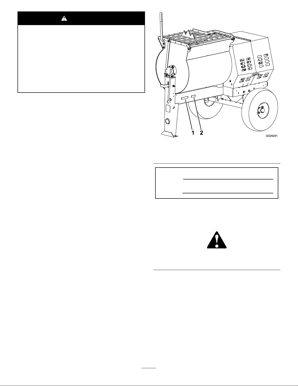
1.Modelandserialnumber
location
ModelNo.
Figure1
2.Vehicleidentication
number(VIN)location
YoumaycontactTorodirectlyatwww .Toro.comforproduct
safetyandoperationtrainingmaterials,accessoryinformation,
helpndingadealer,ortoregisteryourproduct.
Wheneveryouneedservice,genuineT oroparts,oradditional
information,contactanAuthorizedServiceDealerorToro
CustomerServiceandhavethemodelandserialnumbersof
yourproductready .Writethenumbersinthespaceprovided.
SerialNo.
Thismanualidentiespotentialhazardsandhassafety
messagesidentiedbythesafetyalertsymbol(Figure2),
whichsignalsahazardthatmaycauseseriousinjuryordeath
ifyoudonotfollowtherecommendedprecautions.
Figure2
1.Safetyalertsymbol
Thismanualuses2wordstohighlightinformation.
Importantcallsattentiontospecialmechanicalinformation
andNoteemphasizesgeneralinformationworthyofspecial
attention.
TheDOTtireinformationislocatedonthesideofeachtire.
Thisinformationgivesloadandspeedratings.Replacement
tiresshouldhavethesameorbetterratings.
Note:Thevariousmachinesinthismanualhavedifferent
weights;refertoSpecications(page11)toensurethatthe
tiresonyourmachinemeetorexceedtheweightrequirements
ofyourmachine.
©2015—TheToro®Company
8111LyndaleAvenueSouth
Bloomington,MN55420
Contactusatwww.Toro.com.
2
PrintedintheUSA
AllRightsReserved
Page 3

Contents
Safety
Safety...........................................................................3
SafeOperatingPractices...........................................3
SafetyandInstructionalDecals.................................6
Setup............................................................................7
1InstallingtheDumpHandle...................................7
2InstallingtheTowPole..........................................7
3InstallingtheSafetyChain......................................8
4AdjustingtheMixingPaddles..................................9
ProductOverview..........................................................9
Controls................................................................9
Specications........................................................11
Operation....................................................................12
PreparingtoT owtheMachine..................................12
ConnectingtheLightingWireHarness......................15
ExtendingtheAxle.................................................15
TowingtheMachine...............................................16
PreparingtoUsetheMachine...................................16
OpeningandClosingtheCowl.................................17
PoweringtheMachine.............................................18
StartingandStoppingtheMotor...............................19
ControllingthePaddles...........................................19
MixingtheMaterial.................................................20
UsingtheDrum.....................................................21
Maintenance.................................................................22
RecommendedMaintenanceSchedule(s)......................22
PremaintenanceProcedures........................................22
PreparingtheMachineforMaintenance.....................22
RemovingandInstallingtheDividerPlate..................22
Lubrication...............................................................23
LubricatingtheBearingsandSeals............................23
LubricatingtheMotorBearings................................24
LubricatingtheDriveChain.....................................24
ElectricalSystemMaintenance....................................25
ReplacingtheRear-FacingSideBulbs........................25
ReplacingtheSide-FacingBulbs...............................25
ReplacingtheFrontAmberBulbs.............................25
BeltMaintenance......................................................26
ServicingtheBelts..................................................26
ReplacingtheBelts.................................................27
AligningthePulleys................................................29
DriveChainMaintenance............................................30
CheckingandAdjustingtheDriveChain....................30
PaddleMaintenance...................................................31
AdjustingthePaddles..............................................31
Cleaning...................................................................33
CleaningtheMachine..............................................33
Storage........................................................................33
StoringtheMachine................................................33
Troubleshooting...........................................................34
Schematics...................................................................35
Improperlyusingormaintainingthemachinecanresult
ininjury.Toreducethepotentialforinjury,complywith
thesesafetyinstructionsandalwayspayattentiontothe
safetyalertsymbol
or
Danger
complywiththeinstructionmayresultinpersonalinjury
ordeath.
—personalsafetyinstruction.Failureto
,whichmeans:
Caution
,
W ar ning
SafeOperatingPractices
Thisproductiscapableofamputatinghands.Alwaysfollow
allsafetyinstructionstoavoidseriousinjuryordeath.
WARNING
Machiningorhandlingstone,masonry,concrete,
metal,andothermaterialscangeneratedust,mists,
andfumescontainingchemicals,suchassilica,
knowntocauseseriousorfatalinjuryorillness,
suchasrespiratorydisease,silicosis,cancer,birth
defects,orotherreproductiveharm.
•Controldust,mist,andfumesatthesource
wherepossible.Watershouldbeusedfordust
suppressionwhenfeasible.
•Usegoodworkpracticesandfollowthe
recommendationsofthemanufactureror
suppliers,OSHA,andotheroccupationaland
tradeassociations.
•Alwaysfollowrespiratoryprecautions.
•Whenthehazardsfrominhalationcannotbe
eliminated,theoperatorandanybystanders
shouldweararespiratorapprovedbyOSHAfor
thematerialbeinghandled.
Training
•ReadtheOperator'sManualandothertrainingmaterial.If
theoperator(s)ormechanic(s)cannotreadorunderstand
theinformation,itistheowner'sresponsibilitytoexplain
thismaterialtothem.
•Becomefamiliarwiththesafeoperationoftheequipment,
operatorcontrols,andsafetysigns.
•Alloperatorsandmechanicsshouldbetrained.The
ownerisresponsiblefortrainingtheusers.
•Neverletchildrenoruntrainedpeopleoperateorservice
theequipment.Localregulationsmayrestricttheageof
theoperator.
,
•Theowner/usercanpreventandisresponsiblefor
accidentsorinjuriestopeopleordamagetoproperty.
3
Page 4

Towing
Checkwithyourlocalcountyorstatetowingsafetyregulations
beforetowingthemachine.
•Inordertoreducethepossibilityofanaccidentwhile
transportingthemachineonpublicroads,makesure
thetowingvehicleismechanicallysoundandingood
operatingcondition.
•Turnoffthemotorbeforetransportingthemachine.
•Whentowingwithaballhitch,ensurethattheballhitch
youareusingisthepropersizeforthehitchcoupleron
themachine.
•Whentowingwithapintlehitch,ensurethattheeyeof
thetowpoleisthecorrectdimensionforthepintlehook.
•Inspectthehitchandcouplingforwear.Nevertowthe
machinewithdamagedordefectivehitches,couplings,
chains,orothercomponents.
•Checkthetireairpressureonthetowingvehicleandthe
machine.
•Checkthetiretreadandsidewallfordamageandwear.
•Properlyattachthesafetychainstothetowingvehicle.
•Ensurethatthedirectionalandbrakelightsareworking
properly(ifthemachineisequippedwiththelightkit).
•Ensurethatthedirectional,backup,andbrakelightsof
thetowvehicleareworkingproperly.
•Beforetowing,checktomakecertainyourmachineis
correctlyandsecurelyattachedtothetowingvehicle.
•Ensurethatthesafetychainsareproperlysecuredtothe
vehicle,andleaveenoughslackforturning.
•Donotcarryanymaterialinthemachinewhentowing.
•Avoidsuddenstopsandstarts.Thiscancauseskidding,
orjackkning.Smooth,gradualstartsandstopswill
improvetowing.
•Avoidsharpturnstopreventrolling.Towonlywitha
vehiclethathasahitchdesignedfortowing.Donot
attachtowedequipmentexceptatthehitchpoint.
•Donottowthemachinefasterthan88km/h(55mph).
•Usecautionwhenbackingup;useaspotteroutsidethe
vehicletoguideyou.
•Donotallowanyonetositorrideonthemachine.
Preparation
Becomefamiliarwiththesafeoperationoftheequipment,
operatorcontrols,andsafetysigns.
•Useonlyaccessoriesandattachmentsapprovedbythe
manufacturer.
•Wearpersonalprotectiveequipmentandappropriate
clothingincluding:
–Hardhat
–Respiratorordustmask
–Faceshield
–Safetyglasses
–Hearingprotection
–Safetyshoes
–Longpants
–Shirtwithlongsleevesthataretightatthewrists
–Tight-ttinggloveswithoutdrawstringsorloosecuffs
•Securelonghair,looseclothing,orjewelrythatmayget
tangledinmovingparts.
•Operatingtheequipmentsafelyrequiresthefullattention
oftheoperator.Donotwearradioormusicheadphones
whileoperatingthemachine.
•Ensurethatthemachineisonalevelsurfacebefore
operatingthemachine.
•Chockthetiresofthemachinetopreventunintended
movement.
•Beforeeveryuse:
–Inspectthecoupler,ball,andhitch.
–Ensurethatalllightsarefunctioningproperly(ifthe
machineisequippedwithalightkit).
–Ensurethatthetiresareproperlyinatedas
recommended.
–Ensurethatthelugnutsaretightandtorqued
properly.
–Ensurethatthemachineisproperlysecured.
Operation
•Neverrunthemachineinapoorlyventilatedorenclosed
areawithoutproperrespiratoryprotection.Dustfrom
materialsbeingmixedcanbeveryharmfultooperators
andbystanders.
•Onlyoperatethemachineingoodlightingconditions.
•Beforestartingthemachine,makesurethatthereareno
personsorobstaclesnearorunderthemachine.
•Neverleavearunningmachineunattended.Alwaysstop
themotorandverifythatallmovingpartshavestopped.
•Chockthetireswhenusingthemachine.
•Whennotusingthemachine,chockthetiresorkeepit
attachedtothetowvehicle.
•Keephandsawayfromanymovingparts.Keepfeetaway
fromthetiresandthefrontpost.
•Donotoperatethemachineoutdoorsintherain.
•Donotoperatethemachineundertheinuenceof
alcoholordrugs.
•Ensurethattheareaisclearofotherpeopleorpetsbefore
operatingthemachine.Stopthemachineifanyoneenters
thearea.
•Neverplaceyourhandsoranysolidobjectintothedrum
whenthemachineisinoperation.
•Donottouchpartswhichmaybehotfromoperation.
Allowthemtocoolbeforeattemptingtomaintain,adjust,
orservicethemachine.
•Nevermovethemachinewhilethemotorisrunning.
4
Page 5

•Keepthecowlclosedandlatchedduringoperation.
MaintenanceandStorage
•Ensurethatalltheguardsandshieldsaresecurelyinplace
beforeoperatingthemachine.
•EnsurethattheON/OFFswitchisintheOFFposition
beforeconnectingthemachinetotheelectricalsource.
•Ifthemixingpaddlesstrikeaforeignobjectorifthe
machineshouldstartmakinganunusualnoiseor
vibration,stopthemotorandemptythedrum.Waitfor
allmovingpartstocometoacompletestopandcool.
Vibrationisgenerallyawarningoftrouble.Inspectfor
cloggingordamage.Cleanandrepairand/orreplace
damagedparts.
•Lightningcancausesevereinjuryordeath.Ifyousee
lightningorhearthunderinthearea,donotoperatethe
machine;seekshelter.
•Beforeperformingmaintenance,dothefollowing:
–Parkthemachineonlevelground.
–Stopthemotor.Waitforallmovementtostopbefore
adjusting,cleaning,orrepairing.
–Letthemotorcoolbeforeperformingmaintenance
orstoringthemachine.
–Unplugthemachinebeforemakinganyrepairs.
•Neverlubricate,service,repair,oradjustthemachine
whileitisrunning.
•Keepequipmentmaterialsclearfromthemotor.
•Neverallowuntrainedpersonneltoservicethemachine.
•Keephands,feet,andclothingawayfrommovingparts.
Ifpossible,donotmakeadjustmentswiththemotor
running.
•Keepallpartsingoodworkingconditionandallhardware
tightened.Replaceallwornordamageddecals.
•Removeanybuildupofgrease,oil,ordebrisfromthe
machine.
•Donotmodifytheelectricalconnectorsorwiring.
•Donotconnectthegroundcircuitofthemachinetothe
energizedcircuitoftheelectricalsource.
•Donottamperwithsafetydevices.
•Chockthetireswhenstoringthemachine.
•Keepallnuts,bolts,screws,andhoseclampssecurely
tightened.Keepequipmentingoodcondition.
•Toensureoptimumperformanceandcontinuedsafety
certicationofthemachine,useonlygenuineToro
replacementpartsandaccessories.Replacementparts
andaccessoriesmadebyothermanufacturerscouldbe
dangerous,andsuchusecouldvoidtheproductwarranty..
5
Page 6
SafetyandInstructionalDecals
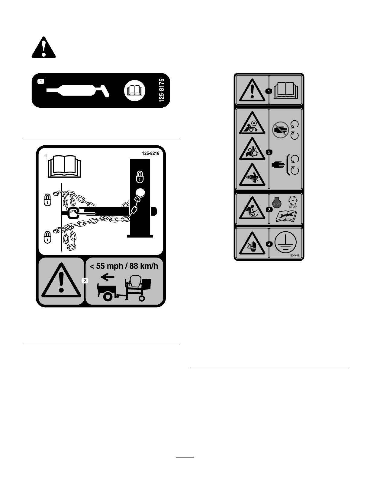
Safetydecalsandinstructionsareeasilyvisibletotheoperatorandarelocatednearanyareaofpotential
danger.Replaceanydecalthatisdamagedorlost.
125–8175
1.ReadtheOperator’sManualforinformationongreasing
themachine.
1.ReadtheOperator’s
Manualforinformationon
howtotowthemachine.
125–8216
2.Warning—limittowing
speedtolessthan55mph
/88km/h.
1.Warning—readthe
Operator’sManual.
2.Handandarm
entanglementatthe
beltdrive;crushinghazard
ofhand;entanglement
hazardofhandatthe
shaft—keephandsaway
frommovingparts;keep
allguardsandsafetiesin
place.
127–1652
3.Entanglementhazardat
paddles—stopthemotor
andwaitforallmoving
partstostopbefore
servicingthemachine.
4.Shockhazard—makesure
themachineisgrounded
beforeoperation.
6
Page 7
Setup
LooseParts
Usethechartbelowtoverifythatallpartshavebeenshipped.
ProcedureDescription
1
2
3
4
1
InstallingtheDumpHandle
Partsneededforthisprocedure:
1Dumphandle
2Bolt
2Nut
Dumphandle1
Bolt2
Nut2
Towpolekit(soldseparately)
Safetychain(soldwithoptionaltowpole
kit)
Connectinglink(soldwithoptionaltow
polekit)
Nopartsrequired
Qty.
Installthedumphandle.
1Installthetowpole.
1
Installthesafetychain.
2
–
Adjustingthemixingpaddles.
Use
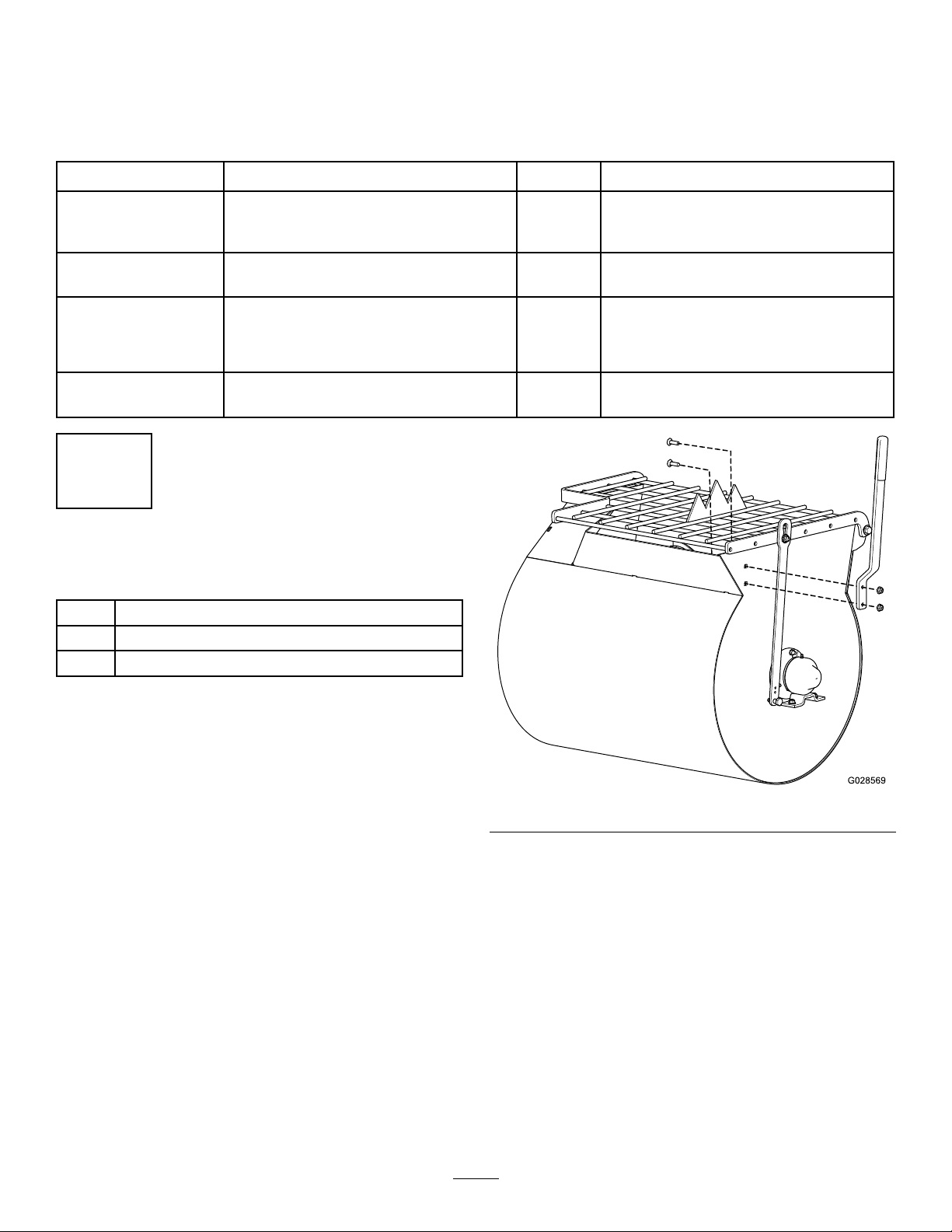
InstallingtheDumpHandletotheDrum
1.Cutthecabletiestoremovethedumphandlefrom
theundersideofthegrate.
2.Positionthedumphandlesothattheboltholesalign
withtheboltholesinthedrum(Figure3).
Figure3
3.Insert1ofthecarriageboltsintothesquarebolthole
andslidethecorrespondingholeofthedrumhandle
overit.(Figure3).
4.Installanutontothebolt,andtightenit.
5.Repeatthepreviousstepsfortheremainingcarriage
bolt.
7
Page 8
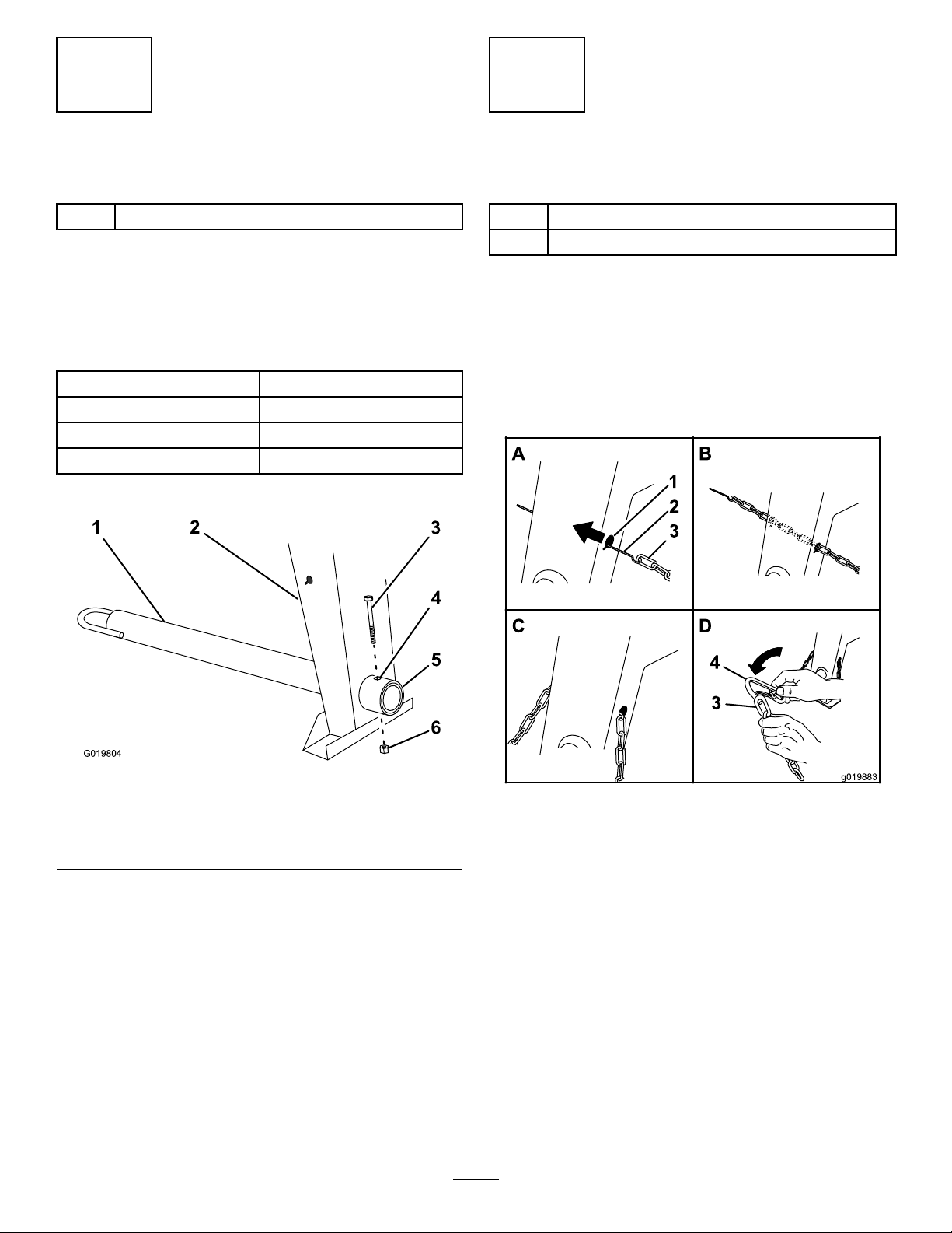
2
5
1
2
4
6
3
G019804
A
B
D
g019883
2
3
4
3
1
3
InstallingtheTowPole
Partsneededforthisprocedure:
1
Towpolekit(soldseparately)
InstallingtheTowPoletotheMachine
Note:Thetowpoleispurchasedseparatelyandincludesthe
nutandboltneededforinstallation.
Themachinehasthefollowingtowpoleoptions:
HitchTypeLength
50mm(2inch)ball—stamped78.7cm(31inches)
50mm(2inch)ball—forged78.7cm(31inches)
Pintle
1.Removetheboltandnutfromthetowpole(Figure4).
78.7cm(31inches)
InstallingtheSafetyChain
Partsneededforthisprocedure:
1
Safetychain(soldwithoptionaltowpolekit)
2
Connectinglink(soldwithoptionaltowpolekit)
InstallingtheSafetyChain
Note:Thesafetychainispartoftheoptionaltowpolekit.
1.Formahookontheendofabendablepieceofrod
orstiffwire(notincluded),andinsertitthroughboth
keyholesinthefrontpostofthemachine(AofFigure
5).
Figure4
1.Towpole4.Bolthole
2.Frontpost
3.Bolt6.Nut
2.Slidethetowpoleforwardandaligntheholeinthe
polewiththeholeintheframetting(Figure4).
3.Inserttheboltthroughtheholesinthettingandthe
pole(Figure4).
4.Threadthenutontotheboltandtightenthemuntil
theyaretightagainsttheframetting(Figure4).
Note:Iftheself-lockingnyloninsertinthelocknut
wearswithuse,replacethenutwithanewGrade5or
Grade8locknut.
5.Frametting
Figure5
1.Keyhole
2.Rodorwire(notincluded)4.Connectinglink
2.Attachthesafetychaintothelengthofrodorwire(A
ofFigure5).
3.Pulltherod,orwire,andthesafetychainthroughboth
keyholes(BofFigure5).
Note:Ensurethatapproximatelyequallengthsof
safetychainextendfromeithersideofthefrontpost.
8
3.Safetychain
Page 9
InstallingtheConnectingLinks
Note:Theconnectinglinksarepartoftheoptionaltowpole
kit.
1.Aligntheconnectinglinktothelastlinkin1endofthe
safetychain(DofFigure5).
2.Inserttheconnectinglinkthroughthechainlinkuntil
theconnectinglinksnapsclosed.
3.Repeatsteps1and2toinstalltheotherconnectinglink
intheotherendofthesafetychain.
4
AdjustingtheMixingPaddles
NoPartsRequired
ProductOverview
Procedure
Ifthemixingpaddlesandwipersneedadjustment,adjustthe
paddlesandwipers;refertoAdjustingthePaddles(page31).
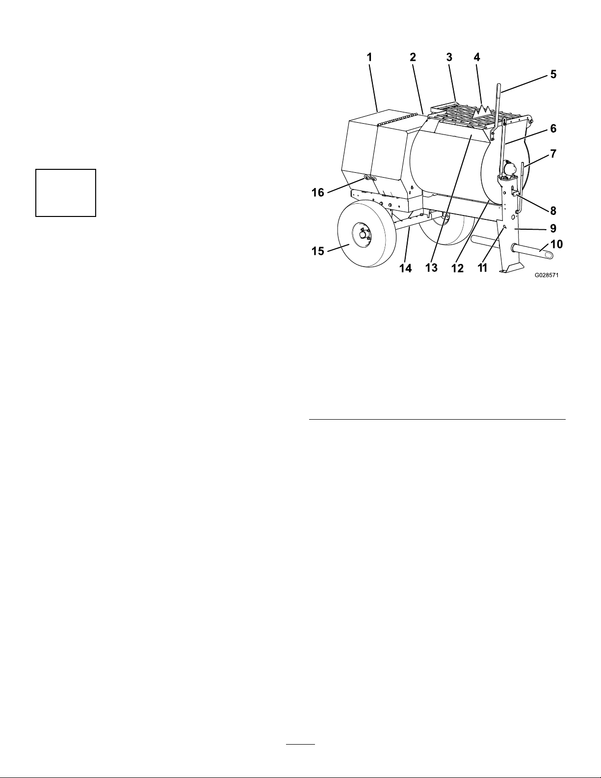
Figure6
Rightside
1.Rearcowl
2.Frontcowl8.Drumlatch14.Axle
3.Grate
4.Bagsplitter10.Towpole
5.Dumphandle
6.Grateliftarm
7.Clutchlever13.Chute
9.Frontpost15.Wheel
assembly
16.Cowllatch
11.Safety-chain
keyhole
12.Drum
Controls
Becomefamiliarwithallthecontrolsbeforeyoustartthe
motorandoperatethemachine.
ClutchLever
Theclutchleverisusedtoengageanddisengagemotor
powertothepaddles.
9
Page 10
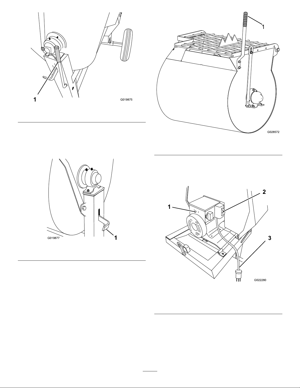
G019875
1
1.Clutchlever
1
G019877
G022280
3
1
2
Figure7
DrumLatch
Thedrumlatchsecuresthedrumtothemixposition(upright)
formixingoperationsandwhentransportingthemachine.
Figure8
1.Drumlatch
DumpHandle
Figure9
1.Dumphandle
MotorControls
Thefollowingmotorcontrolsarefoundonallmodels:
Usethedumphandletorotatethedrumtothedumpposition
andtorotatethedrumtothemixposition(upright).
Figure10
1.Thermal-overload
protectorresetbutton
2.ON/OFFswitch
10
3.Powercord
Page 11
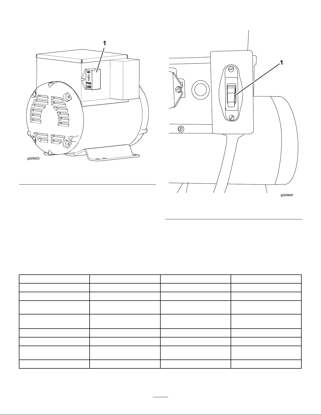
VoltageBlock
g020669
1
Usethevoltageblocktosettheoperatingvoltageforthe
machine(Figure10).
Figure11
motor.RotatetheON/OFFswitchtotheOFFpositionto
stopthemotor.
1.Voltageblock
MotorON/OFFSwitch
TheON/OFFswitch(Figure12)allowstheoperatorofthe
1.MotorON/OFFswitch
Figure12
machinetostartandstopthemotor.Thisswitchislocatedon
thefrontofthemotor.Itismarked(ON)and(OFF).Rotate
theON/OFFswitchtotheONpositiontostartandrunthe
Specications
Note:Specicationsanddesignaresubjecttochangewithoutnotice.
MachineSpecications
Model
BatchCapacity0.17cubicm(6.0cubicft)0.23cubicm(8.0cubicft)0.23cubicm(8.0cubicft)
TotalVolume
Length
(withouttowpole)
Width
68012C68018C68019C
0.20cubicm(6.9cubicft)0.25cubicm(9.0cubicft)0.25cubicm(9.0cubicft)
163cm(64inches)193cm(76inches)193cm(76inches)
86cm(34inches)86cm(34inches)86cm(34inches)
Height
Weight
Axle
Motor1.5hpBaldorElectric1.5hpBaldorElectric2hpBaldorElectric
137cm(54inches)137cm(54inches)137cm(54inches)
250kg(550lb)275kg(605lb)275kg(605lb)
86to117cm(34to46inches)
extendable
86to117cm(34to46inches)
extendable
11
86to117cm(34to46inches)
extendable
Page 12
Operation
G019741
G020836
Important:Beforeoperating,removeanydebrisfrom
themachine.Ensurethattheareaisclearofpeople.
CheckingtheTiresandWheels
ServiceInterval:Beforeeachuseordaily—Inspectthetires
andwheels.
WARNING
PreparingtoTowtheMachine
Important:Ensurethatyourtowvehiclehastowing
capacityfortheweightofthemachine.
Important:UseaClass2orlargerreceiver.
Note:Ensurethatyourtowvehiclehastheappropriatehitch
totowthemachine;optionsincludea50mm(2inch)ball
hitchorapintlehitch.
Note:Ifthemachineisequippedwithatrailer-lightkit,
ensurethattheelectricalconnectorofthetowvehicleis
compatiblewiththeelectricalconnectorofthemachine.The
machineusesastandard4-atplug.Ifyourtowvehiclehasa
differenttypeofplug,obtainanadapterfromanautomotive
partsstore.
1.Stopthemotor,unplugthemachine,andemptythe
drum.
2.Ifthedrumhasaccumulatedanywater,dumpthe
drum;refertoDumpingtheDrum(page21),steps1,
3,4,and5.
3.Usingthedumplever,positionthedrumsothatitisin
themixposition(upright)andlocked.
Failuretomaintaincorrecttirepressuremayresult
intirefailureandlossofcontrol,resultingin
propertydamageandseriousinjuryordeath.
•Checkthetirepressurefrequentlytoensure
properination.Ifthetiresarenotinatedto
thecorrectpressure,theywillwearprematurely.
•Inspectthetireconditionbeforetowingand
afteranyoperatingaccident.
TheDOTtireinformationislocatedontheside
ofeachtire.Thisinformationgivesloadandspeed
ratings.Replacementtiresshouldhavethesame
orbetterratings.Formoreinformationgoto
http://www.nhtsa.gov/Vehicle+Safety/Tires.
Note:Thevariousmachinesinthismanualhavedifferent
weights;refertoSpecications(page11)toensurethatthe
tiresonyourmachinemeetorexceedtheweightrequirements
ofyourmachine.
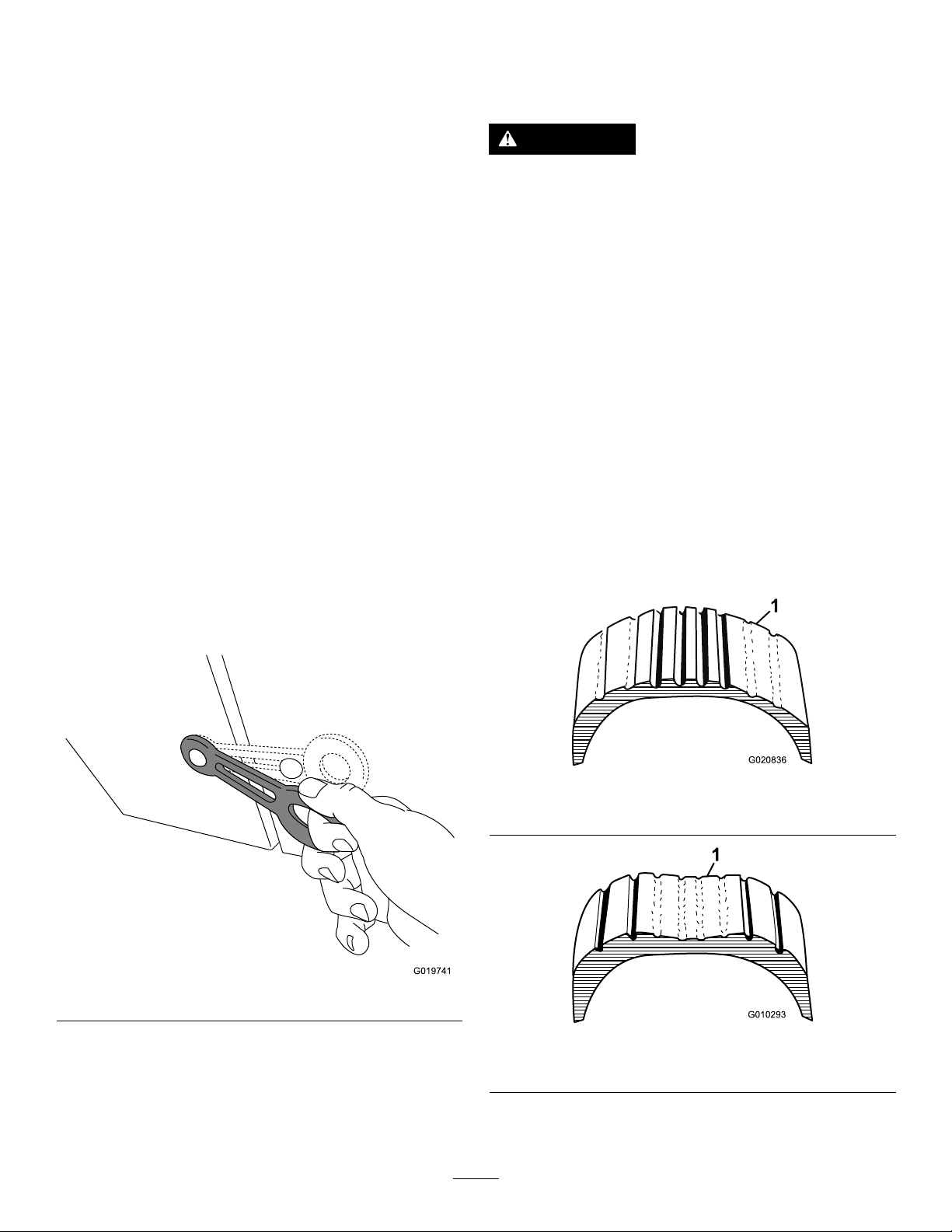
1.Visuallyinspectthetiresfordamageandwear(Figure
14andFigure15).
4.Closethecowlandsecurethecowllatches(Figure13).
Figure13
5.Extendtheaxle;refertoAdjustingtheAxleWidth
(page15).
Figure14
1.Exampleoftirewearcausedbyunderination
Figure15
1.Exampleoftirewearcausedbyoverination
2.Ensurethatthetiresareinatedtothecorrectair
pressure.ThefollowingTireAirPressuretableshows
12
Page 13
theappropriateairpressureforthetiresasinstalledat
1
2
3
4
G021 107
A
B
C
G020359
2
1
thefactory.
Important:Alwayschecktheinformation
ontheactualtiresforthecorrectairpressure
requirement.
Important:Themostcommoncauseoftire
troubleisunder-ination.Maintainfullair
pressure.
TireAirPressure
ModelTirepressure
68012CMax414kPa(60psi)
68018C,68019CMax241kPa(35psi)
3.Ensurethatthewheellugnutsaretorquedto108to
122N-m(80to90ft-lb).
Note:Checkthetorqueofthewheellugnutsinitially
andaftertowing.
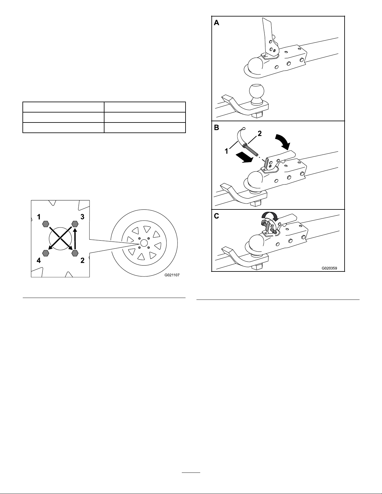
Note:Torquethelugnutsinthesequenceshownin
(Figure16).
Figure16
HitchingaMachinewithaStampedBall
Coupler
1.Applychassisgreasetothesocketofthecouplerand
theareaoftheclampthatcontactstheball.Oilthe
pivotpointsandslidingsurfacesofthecouplerwith
SAE30motoroil.
2.Openthecouplerlatch(AofFigure17).
Figure17
1.Bail
2.Safetypin
3.Positionthecouplerontopofthehitchball(Bof
Figure17).
4.Closethecouplerlatch(BofFigure17).
5.Openthebailonthesafetypinandinsertthepin
throughtheholeinthelatch(BofFigure17).
6.Rotatethefreeendofthebailovertheendofthe
safetypinthatisprotrudingthroughthelatch(Cof
Figure17).
7.Ifthemachineisequippedwithatrailer-lightkit,
connectthewireplugofthetowvehicletothewire
plugofthemachine.
HitchingaMachinewithaForgedBall
Coupler
1.Applyremovablethread-lockingcompoundtothe
threadsofthecouplerbolttopreventthecoupler
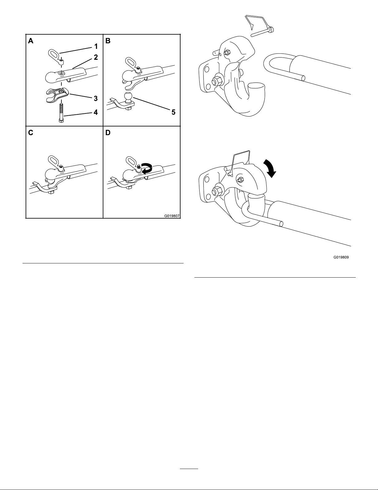
handlefromcomingloose(AofFigure18).
13
Page 14
Important:Applythread-lockingcompoundas
A
B
D
G019807
5
1
2
3
4
G019809
neededinthefuture.
Figure18
1.Couplerhandle
2.Coupler
3.Clamp
4.Bolt
5.Hitchball
2.Applychassisgreasetothesocketofthecouplerand
theareaoftheclampthatcontactstheball.
3.Pushthecouplerboltupthroughthecouplerclamp
andthecouplertop,andconnectthecouplerhandleto
thebolt(AofFigure18).
4.Positionthecouplersothesocketisontopofthehitch
ballandtheclampisundertheball.
5.Turnthecouplerhandleclockwisetothreaditontothe
boltuntilitissecure(DofFigure18).
Note:Useawrenchtokeeptheboltfromspinning.
6.Ifthemachineisequippedwithatrailer-lightkit,
connectthewireplugofthetowvehicletothewire
plugofthemachine.
HitchingaMachinewithaPintleHitch
TowPole
1.Removethepinfromthepintlehitchandopenit
(Figure19).
Figure19
2.Positiontheringonthetowpoleontothehookofthe
pintlehitch(Figure19).
3.Closethetopofthepintlehitchandsecureitwiththe
pin(Figure19).
4.Ifthemachineisequippedwithatrailer-lightkit,
connectthewireplugofthetowvehicletothewire
plugofthemachine.
ConnectingtheSafetyChainstothe
TowVehicle
Connectthesafetychaintothemachineandthetowvehicle
asfollows:
1.Pullthesafetychainthroughtheslotsinthekeyholes
locatedinthefrontpostofthemachine,sothatthere
isjustenoughslackoneachsideforturningaround
cornerswhentowingthemachine(Figure20).
Note:Stowtheexcesschaininsidethebottomofthe
frontpostbypushingitintothekeyholesandlatching
theappropriatelinksintothekeyholeslots.
2.Crossbothlengthsofchainunderthetowpole.
14
Page 15
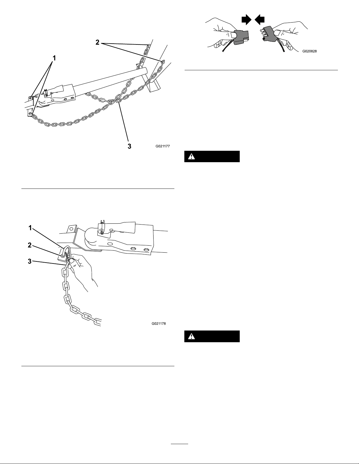
Note:Crossingthechainsdecreasesthechancesof
1
2
3
G021 177
G021 178
1
2
3
G020828
thefrontofthemachinedroppingtothegroundifthe
hitchdoesnotholdtheconnection.
Figure22
Note:Themachineusesastandard4-atplug.Ifyourtow
vehiclehasadifferenttypeofplug,obtainanadapterfroman
automotivepartsstore.
Important:Routinelycheckthelightstoensurethat
theyareworkingproperly,includingthetaillights,brake
lights,andeachappropriateturnsignal.
ExtendingtheAxle
Figure20
1.Connectinglinks3.Chaincrossedundertow
pole
2.Keyholesinfrontpost
3.Connecteachlengthofchaintothesafetychain
mountingpointonthetowvehiclewiththeconnecting
links(Figure21).
WARNING
Themachineisnotstablewhentowingitwiththe
axleinthenarrowposition.
Towthemachinewiththeaxleinthewideposition.
Important:Adjusttheaxletothenarrowpositiononly
tomovethemachinethroughanarrowaccesspoint,
suchasthegateofafenceorthedoorwayofabuilding.
PreparingtoChangetheAxleWidth
1.Movethemachinetoaleveljob-sitesurface.
2.Disconnectthemachinefromthetowvehicle.
3.Chockthetires.
4.Ensurethatthedrumisemptyandinthemixposition
(upright).
5.Ensurethatthedrumlatchisengagedandthatthe
drumdoesnotrotatetowardthedumpposition.
AdjustingtheAxleWidth
Figure21
1.Connectinglink3.Chainlink
2.Safetychainmounting
pointontowvehicle
WARNING
Mechanicalorhydraulicjacksmayfailtosupport
themachineandcauseseriousinjury.
Usejackstandswhensupportingthemachine.
ConnectingtheLightingWire Harness
Connecttheelectricalplugofthemachinewiththeelectrical
plugofthetowvehicle,asshownin(Figure22).
1.Alignajackwithanadequateliftheightandweight
capacityundertheaxle;refertoSpecications(page
11).
2.Liftthemachineuntilthetiresareofftheground.
3.Useajackstandateachsupportpointontherear
frameextension(Figure23).
15
Page 16
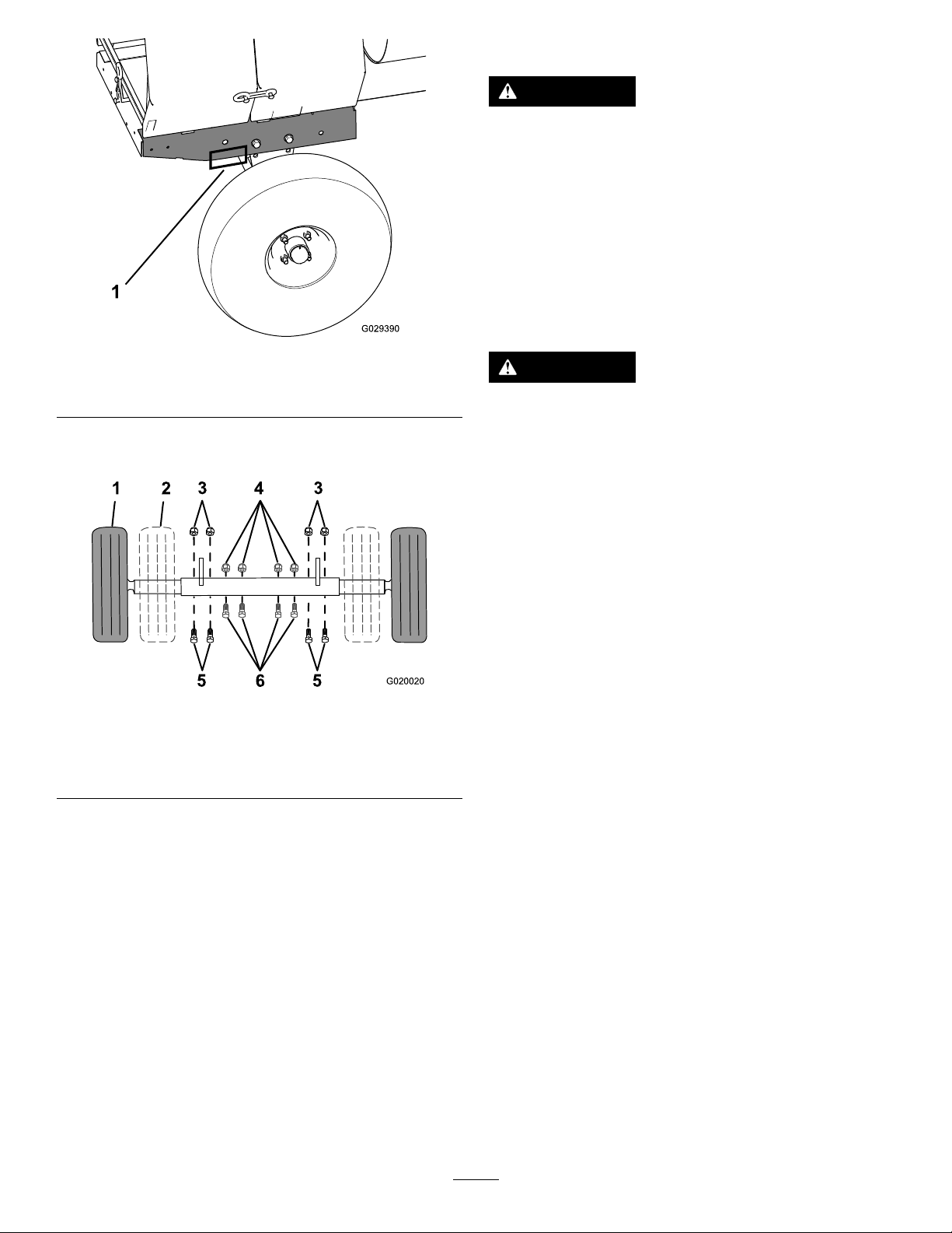
1 2
3
4
3
5
6
5
G020020
TowingtheMachine
WARNING
Towingthemachineathighspeedincreasesthe
riskofahitchmalfunctionandtirefailure.Higher
speedsalsoincreasethemomentumofthemachine
andbrakingdistance.Ifthemachinebecomes
detachedfromthetowvehicleathighspeed,it
couldcausedamagetoproperty,orinjuryordeath
tobystanders.
Donotexceed88km/h(55mph)whentowingthe
machine.Forpoorroadconditionsorinclement
weather,reducespeedaccordingly.
1.Supportpoint(2)
4.Removetheboltsandnutsthatsecuretheinneraxleto
theouteraxle(Figure24).
1.Wideposition(towing)4.Nut(narrowposition)
2.Narrowposition
3.Nut(wideposition)6.Bolt(narrowposition)
5.Aligntheinneraxletothedesiredpositionasfollows:
•Slideeachsideoftheaxleinwardtothenarrow
position(Figure24).
•Slideeachsideoftheaxleoutwardtothewide
(tow)position(Figure24).
6.Aligntheholesoftheinneraxlewiththeholesofthe
outeraxle.
7.Inserttheboltsthroughtheaxleholes(Figure24).
8.Threadthenutsontothebolts,andtorquethenuts
to87N-m(64ft-lb).
Figure23
Figure24
5.Bolt(wideposition)
WARNING
Towingthemachinewithmaterialinthedrum
increasestheriskofahitchmalfunctionandtire
failure.Inaddition,materialcouldbounceoutof
thedrumandhitothervehiclesand/orpeople.
Materialinthedrumincreasestheweight,which
affectsmomentumandbrakingdistance.
Donottowthemachinewithmaterialinthedrum.
•ReviewandunderstandSafeOperatingPractices(page3).
•Testthebrakesofthetowvehiclebeforetowing.
•Avoidsuddenstartsandstopswhiletowingthemachine.
PreparingtoUsetheMachine
•Reviewallofthesafetydecalsonthemachine.
•Useahard-hat,hearingprotection,ashirtwithlong
sleevesthataretightatthewrists,tight-ttinggloves
withoutdrawstringsorloosecuffs,eyeprotection,and
adustmaskorrespirator.Ameshvisoralonedoes
notprovidesufcienteyeprotection;supplementwith
protectiveglasses.
•Ensurethatyouarefamiliarwiththesafetyregulations
andshutdownproceduresdescribedintheOperator’s
Manual.
•Ensurethatallguardsareinplaceandingoodcondition.
•Ensurethatthepaddlesareinplaceandingood
condition.
•Checkallthegreasettingstoensurethatthemachine
isproperlylubricated.
•Whenpreparingtomixmaterial:
1.Movethemachinetoaleveljob-sitesurface.
2.Removethemachinefromthetowvehicle.
3.Chockthefrontandbackofthetirestoprevent
themachinefrommoving.
4.Ensurethatthedrumisinthemixposition
(upright).
16
Page 17
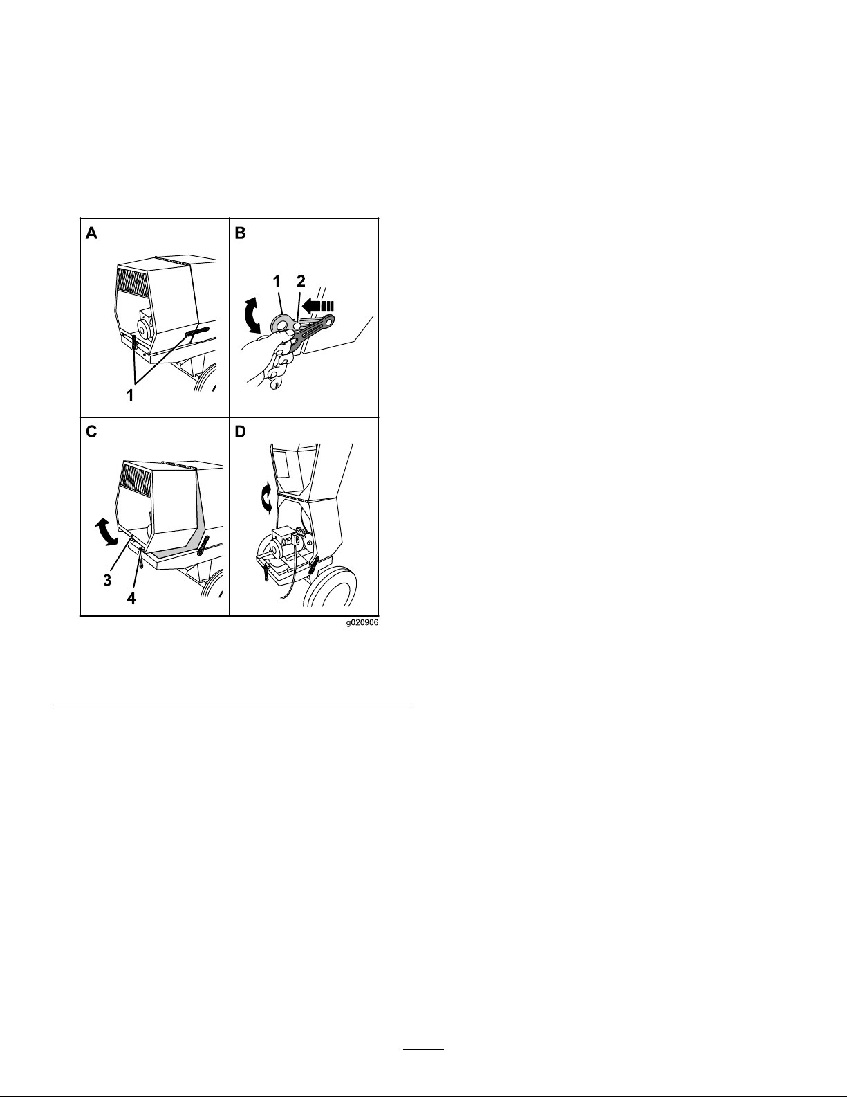
5.Ensurethatthedrumlatchisengagedandthatthe
A
B
D
1
2
3
4
1
g020906
drumdoesnotrotatetowardthedumpposition.
OpeningandClosingtheCowl
OpeningtheCowl
1.Atthesideofthemachinewherethefrontcowland
rearcowlmeet,graspthelatchandpullitofffromthe
latchanchorontherearcowl(BofFigure25).
4.Repeatstep3attheoppositesideofthemachine(Bof
Figure25).
Figure25
1.Latch3.Receiver
2.Latchanchor
2.Repeatstep1ontheoppositesideofthemachine.
3.Atthebackofthemachinewheretherearcowlmeets
theframeofthemachine,graspthelatchandpullitoff
fromthelatchanchoronthecowl(BofFigure25).
4.Rotatetherearcowlupandforwarduntilitisfully
positionedontopofthefrontcowl(DofFigure25).
ClosingtheCowl
1.Rotatetherearcowlrearwardanddownuntilthe
receiveratthebottomcenterofthecowlisalignedwith
theV -ttingandushontheframeofthemachine
(DofFigure25).
2.Atthebackofthemachine,graspthelatchandpullit
ontothelatchanchorontherearcowl.
3.Atthesideofthemachine,graspthelatchandpullit
ontothelatchanchorontherearcowl(BofFigure25).
4.V-tting
17
Page 18
PoweringtheMachine
Important:Useonlyextensioncordswithterminals
andsocketsforthelive,neutral,andgroundwires.
SettingtheOperatingVoltage
Themachinecanoperatewitha115Vor230Vsupply
voltage.Thevoltageblockdeterminestheoperatingvoltage
ofthemachine(Figure11).Usethefollowingstepstochange
theoperatingvoltage:
1.Parkthemachineonlevelground.
2.Stopthemotorandunplugthemachine.
3.Removethe2screwssecuringthevoltageblocktothe
motor.
4.Removethevoltageblockfromthemotor,rotatethe
voltageblock180degreesandplugitbackintothe
motor.
5.Securethevoltageplugtothemotorwiththe2screws
thatyoupreviouslyremoved.
Note:Usetheinstructionsonthevoltageblocktodetermine
thevoltageblocksetting.
SettingtheOperatingVoltage
Themachinecanoperatewitha115Vor230Vsupply
voltage.Thevoltageblockdeterminestheoperatingvoltage
ofthemachine(Figure11).Usethefollowingstepstochange
theoperatingvoltage:
1.Parkthemachineonlevelground.
2.Stopthemotorandunplugthemachine.
3.Removethe2screwssecuringthevoltageblocktothe
motor.
4.Removethevoltageblockfromthemotor,rotatethe
voltageblock180degreesandplugitbackintothe
motor.
5.Securethevoltageplugtothemotorwiththe2screws
thatyoupreviouslyremoved.
Note:Usetheinstructionsonthevoltageblocktodetermine
thevoltageblocksetting.
ConnectingtoaPowerSource
DANGER
Contactwithwaterwhileoperatingtheproduct
couldcauseelectricshock,causinginjuryordeath.
Important:Connectthemachinetoonlyareceptacle
withlive,neutral,andgroundconnections.
Important:Theconnectingwiresorextensioncord
shouldbeasshortaspossibleandin1piece.
Toreducetheriskofelectricshock,thismachinehasa
polarizedplug(uniquebladeshapesandwidths).Useonly
apolarizedplugandsocketthatiscompliantwithNEMA
specicationsandanextensioncordthatisUL-listed(CSA
certiedinCanada)andrecommendedforoutdooruse.A
polarizedplugwilltinapolarizedcordonly1way .Ifthe
plugdoesnottfullyintothecord,turnthecord.Ifit
stilldoesnott,purchaseanappropriateextensioncord.
Ifyouhaveapolarizedextensioncordandtheextension
cordplugdoesnottfullyintothewallreceptacle,turnthe
plug.Ifitstilldoesnott,contactaqualiedelectricianto
installtheproperoutlet.Donotchangethemachineplugor
extension-cordpluginanyway.
Note:Themachineusesatwist-lockingplug.
ExtensionCords
Length
15.2m(50ft)10AWG
22.8m(75ft)10AWG
30.4m(100ft)8AWG
Note:Donotuseanextensioncordover30.4m(100ft)
long.
WireGauge
PoweringtheMachinewithaPortable
Generator
Whenusingaportablegeneratorasanelectricalsource,
ensurethefollowingpoweroutputspecications:
ModelVoltageAmperesKilowatt
60212C115V/
230V
60218C115V/
230V
60219C115V/
230V
19A/
9.5A
19A/
9.5A
24A/
12A
hour
2.2to2.3
Kw
2.2to2.3
Kw
2.2to2.3
Kw
Frequency/
phase
60Hz/
single
60Hz/
single
60Hz/
single
•Donothandletheplugorthemachinewithwet
handsorwhilestandinginwater.
•Useonlyanextensioncordrecommendedfor
outdoorcold-weatheruse.
Important:Checktheextensioncordfrequentlyduring
useforholesorcracksintheinsulation.Donotusea
damagedcord.Donotrunthecordthroughstanding
waterorwetgrass.
ResettingtheMotor
Theelectricalmotorforthemachineisequippedwitha
deviceforthermal-overloadprotection.Intheeventthatthe
motorshutsdownautomatically,resetthethermal-overload
protectorasfollows:
1.MovetheON/OFFswitchtotheOFFposition;refer
to(Figure12).
18
Page 19
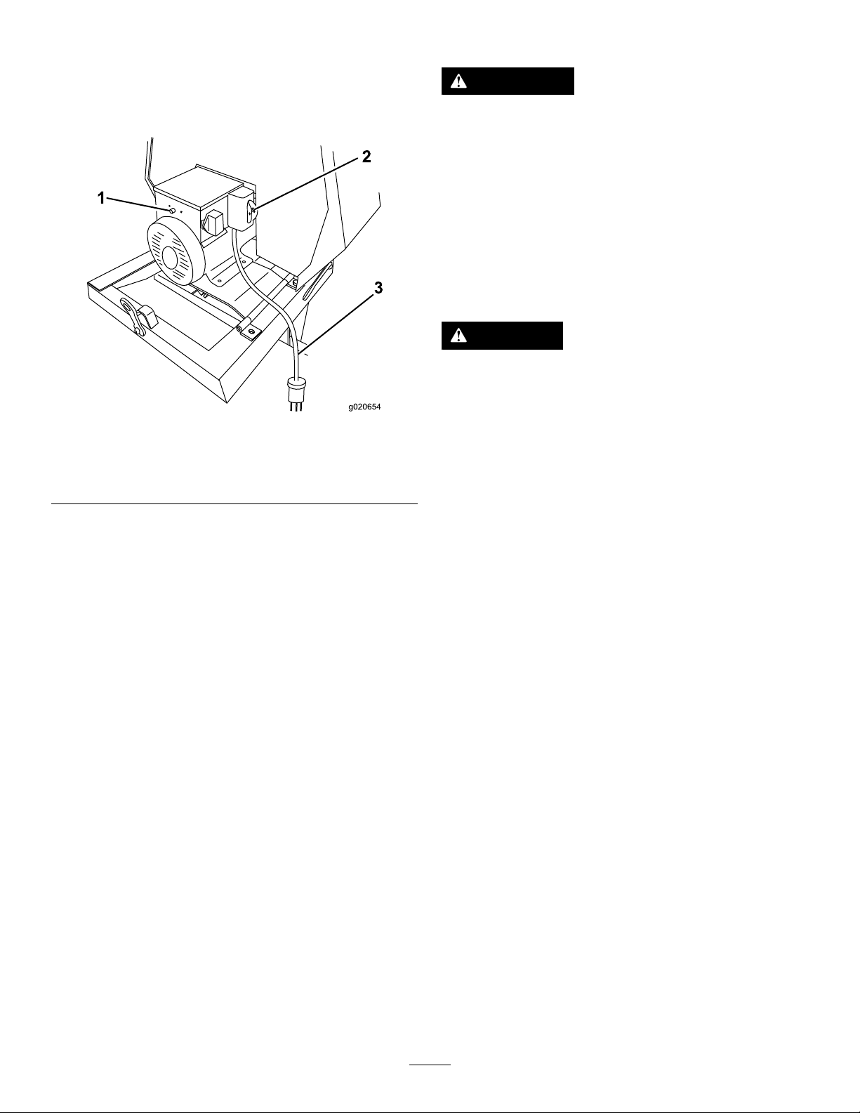
2.Disconnecttheelectricalplugforthemachinefromthe
3
powersource(Figure26).
Figure26
1.Thermal-overload
protectorresetbutton
2.ON/OFFswitch
3.Electricalplug
StoppingtheMotor
WARNING
Inanemergencysituation,stopthemotor
immediately.
1.MovetheclutchlevertotheOFFposition;referto
ControllingthePaddles(page19).
2.SwitchtheON/OFFswitchtotheOFFposition;refer
toMotorON/OFFSwitch(page11).
3.Unplugthepowercord.
ControllingthePaddles
DANGER
Thismachineiscapableofamputatinghands.
•Stayintheoperator’spositionwhilethemachine
isrunning.
•Keepallbystandersasafedistancefromthe
machine.
•Stopthemachineimmediatelyifanypeopleor
animalsentertheworkarea.
3.Allowtheelectricmotorofthemachinetocooluntilit
iswarmtothetouchorcooler.
Important:Ensurethatthepaddlesspinfreely.
Checkforstone,masonry,orconcretematerial
betweenthepaddlesandthedrum.
4.Onthesideofthejunctionboxforthemotor,press
theresetbuttonforthethermal-overloadprotector
(Figure26).
5.Connecttheelectricalplugforthemachinetothe
powersource.
6.RotatetheON/OFFswitchtotheONpositionand
ensurethatthemotorstartsnormally.
7.RotatetheON/OFFswitchtotheOFFposition.
StartingandStoppingthe Motor
StartingtheMotor
1.Plugthepowercordintoaproperelectricaloutlet.
•Neverplaceanypartofyourbodyintoaposition
thatcausesanunsafeoperatingcondition.
Important:Ensurethatthepaddlesdonotturnwhen
theclutchleverisintheOFFposition.
Usetheclutchlevertocontrolthepowertransmissiontothe
paddlesofthemachine.
2.SwitchtheON/OFFswitchtotheONposition.
3.MovetheclutchlevertotheONposition;referto
ControllingthePaddles(page19).
19
Page 20
UsingtheClutchLever
G019873
1
2
A
B
D
G021 179
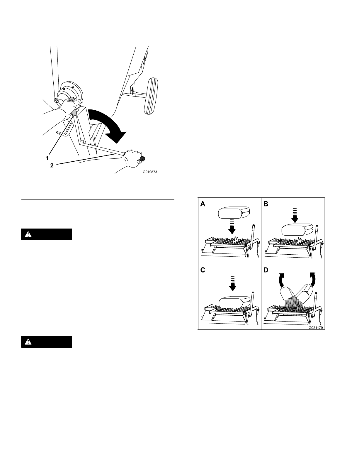
Movetheclutchleverclockwisetoengagetheclutch,and
counterclockwisetodisengagetheclutch(Figure27).
MixingaBatchofMaterialinthe
Machine
1.Ensurethatthereisnoold,loosematerialinthedrum
thatcancontaminatethebatchofmaterial;referto
CleaningtheDrum(page21)andDumpingtheDrum
(page21),thenreturnthedrumtotheuprightposition.
Note:Ensurethatthedrumisinthemixposition
(upright)andthedrumlatchisengaged.
2.MovetheclutchlevertotheOFFposition;referto
ControllingthePaddles(page19).
3.Startthemotor;refertoStartingtheMotor(page19).
4.MovetheclutchlevertotheONposition;referto
ControllingthePaddles(page19).
5.Addtheingredientsforthebatchasfollows:
A.Pourwaterintothedrumthroughthegratingof
thedrumguard.
B.Addtheplaster,cement,orotherbindingmaterial.
Figure27
1.OFFposition2.ONposition
MixingtheMaterial
DANGER
Eyeandskincontactwithconcretematerialsand
breathingthedustinvolvedishazardoustoyour
health.
•Ensurethatthereisadequateairventilation.
•Wearadustmasktopreventinhalationofdust
whileusingthemachine;refertoSafeOperating
Practices(page3).
•Avoiddirectcontactofcementandconcrete
materialswithskinandeyes.
DANGER
Note:Youcanopenbagsofcement,plaster,and
bindingmaterialsbyloweringthebagontothe
bagsplitter(Figure28).
Figure28
Contactwiththemixingpaddlescouldcause
damageorinjury.
Neverputyourhandsinsidethedrumatanytime.
Important:Donotaddmorematerialthanthebatch
capacityofthemachine;refertoSpecications(page11).
Note:Followthemanufacturer’sinstructionsthatareprinted
onthepackagingoftheproductyouareusing.
C.Ifyouareusingsandand/orotherreinforcing
materials,addthemintothedrum.
6.Allowthepaddlestomixthematerialuntilthe
ingredientshaveauniformappearance.
Note:Ifneeded,addwaterorplaster,cement,or
otherbindingmaterialuntiltheconsistencyofthe
batchiscorrect.
7.Releasethedrumlatchanddumpthedrum;referto
DumpingtheDrum(page21).
20
Page 21
UsingtheDrum
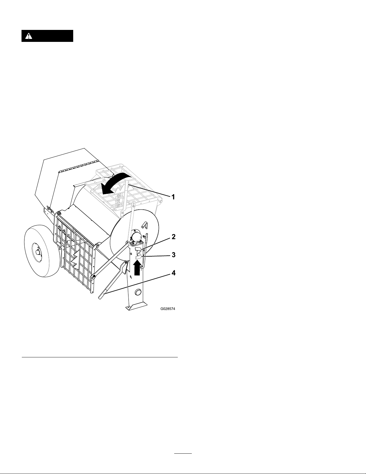
5.Rotatethedumphandleclockwiseuntilthedrum
latchlocksthedrumintheuprightposition(Figure29).
DANGER
Contactwiththemixingpaddlescouldcause
damageorinjury.
Neverputyourhandsinsidethedrumatanytime.
DumpingtheDrum
Note:Whendumpingabatchofmaterial,leavethemotor
runningandtheclutchintheONpositionsotherotating
paddleshelpdischargethematerial.
1.Alignawheelbarroworsimilarcontainerofadequate
capacityinthepathofthedrumopening.
2.Graspthedumphandlewithyourlefthand(Figure29).
6.Afterdischargingabatchofmaterial,cleanthedrum;
refertoCleaningtheDrum(page21).
Note:Thisstepwillcleanthepaddlesanddrum
betweenbatchesandpreventdriedmaterialfrom
forming,andcontaminatingthenextbatchofmaterial.
CleaningtheDrum
Important:Donotstrikeonthedrumwithashovel,
hammer,oranyotherdevicetoloosenanyaccumulated
driedmaterials.
1.Stoptherotationofthepaddlesbymovingtheclutch
levertotheOFFposition;refertoControllingthe
Paddles(page19).
2.MovethemotorON/OFFswitchtotheOFFposition;
refertoMotorON/OFFSwitch(page11).
3.Ensurethatthedrumisinthemixposition(upright);
refertoDumpingtheDrum(page21),step5.
4.Spraythemachinewithwatertoremoveany
accumulatedmaterial.
5.Startthemotor;refertoStartingtheMotor(page19).
Figure29
1.Dumphandle(mix
position)
2.Drumlatch(release
position)
Note:Whendumpingabatchofmaterial,aligna
wheelbarroworasimilarcontainerofadequatecapacity
beneaththechute.
3.Drumlatch(locked
position)
4.Dumphandle(dump
position)
6.Starttherotationofthepaddlesbymovingtheclutch
levertotheONposition;refertoControllingthe
Paddles(page19).
7.Dumpthedrum;refertoDumpingtheDrum(page
21).
3.Liftthehandleofthedrumlatch(Figure29).
4.Withbothhandsonthedumphandle,rotateit
counterclockwisetodischargethecontentsofthe
drum(Figure29).
Note:Allowthemachinetocompletelydischargethe
contentsofthedrum.
21
Page 22
Maintenance
G021585
Important:Beforeperforminganymaintenanceprocedures,rststopthemotor,wait5minutestoallowallmoving
partstocometoacompletestopandcool,andunplugthepowercord.
RecommendedMaintenanceSchedule(s)
MaintenanceService
Aftertherst10hours
Aftertherst25hours
Beforeeachuseordaily
Aftereachuse
Every40hours
Every50hours
Every6,000hours
Every2years
Premaintenance
Interval
Monthly
MaintenanceProcedure
•Checkthetensionofthedrivechain,andadjustitasneeded.
•Inspectthebeltsandadjustasnecessary.
•Inspectthetiresandwheels.
•T orquethelugnutsto108to122N-m(80to90ft-lb)aftertowing.
•Cleanthedrumbetweenmixingbatchesofmaterial.
•Lubricatethetrunnions.
•Cleanthemachine.
•Lubricatethedrivechainwithanon-stickychainlubricant.
•Inspectthebeltsandadjustasnecessary.
•Checktheclutchoperation.
•Checkthetensionofthedrivechain,andadjustitasneeded.
•Lubricatethemotorbearings.
•Lubricatethepillow-blockbearings.
•Replacethebelts.
RemovingtheDividerPlate
Procedures
PreparingtheMachinefor Maintenance
1.Parkthemachineonalevelsurface.
2.Removethemachinefromthetowvehicle.
3.Chockthetires.
4.Opentherearcowl;refertoOpeningtheCowl(page
17).
5.Turnoffandunplugthemotor;refertoStoppingthe
Motor(page19).
6.Ensurethatthemotoriscool.
RemovingandInstallingthe DividerPlate
Youneedtoremovethedividerplatetoprovideaccessbefore
performingsomemaintenanceprocedures.
1.Unlatchandopenthecowl;refertoOpeningtheCowl
(page17).
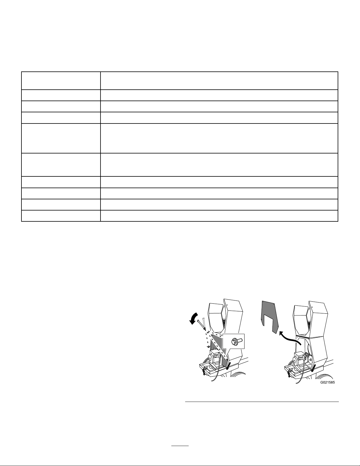
2.Useawrenchtoremovethe4boltsthatsecurethe
dividerplatetothefrontcowl.
Note:Keeptheboltsforinstallingthedividerplate.
Figure30
3.Toremovethedividerplate,liftitupwardandrotateit
counterclockwisesothatitclearsvariouscomponents.
22
Page 23
InstallingtheDividerPlate
G021586
1
3
g021 101
1
2
3
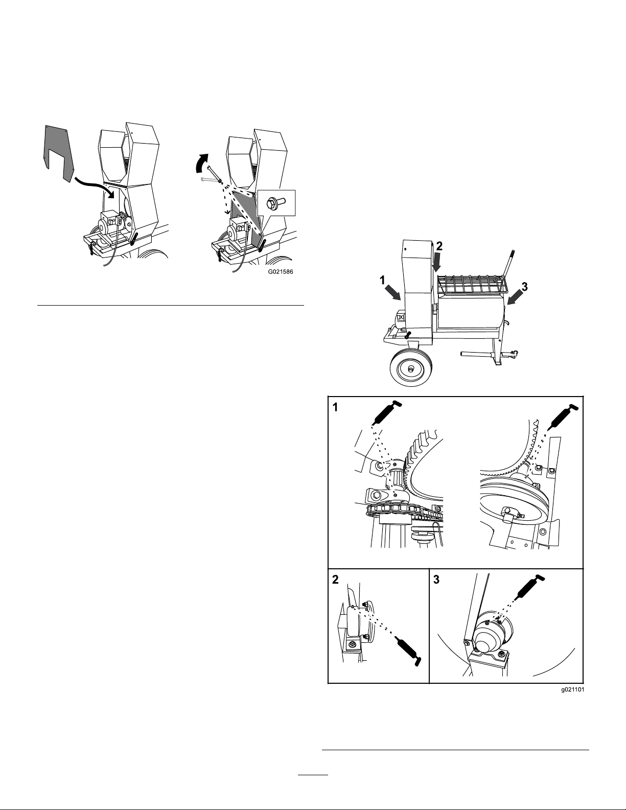
1.Guidethedividerplateintopositionagainstthefront
cowl.
Note:Startwiththedividerplaterotatedslightly
counterclockwise,andthenrotateitclockwisewhile
loweringitintoposition.
Figure31
Note:Ensurethatthedividerplateisnotbackward.
Lubrication
LubricatingtheBearingsand Seals
ServiceInterval:Aftereachuse—Lubricatethetrunnions.
Monthly—Lubricatethepillow-blockbearings.
Note:Thepillow-blockbearingsareinsidethe
cowl—removethedividerplatetoaccessthem;referto
RemovingtheDividerPlate(page22).
Greasetype:Number2general-purposelithium-based
grease.
1.Cleanaroundeachgreasettingwitharagandliftthe
plasticcapoffthegreasetting(Figure32).
2.Aligntheboltholesinthedividerplateandthefront
cowl.
3.Installeachofthe4bolts,andhand-tightenthemto
preventcross-threading.
4.Tightentheboltswithawrenchuntiltheyaresecure.
1.Pillow-blockbearings3.Fronttrunnion
2.Reartrunnion
23
Figure32
Page 24
2.Pumpgreaseintoeachttingasfollows:
G0 215 88
G021584
1
•Forthepillow-blockbearings,pump1shotof
greaseintoeachtting(Figure32).
•Forthetrunnions,pumpseveralshotsofgrease
intoeachttinguntilitstartstooozeoutofthe
bearinghousing(Figure32).
Important:Pumpgreaseinslowlyandcarefully
topreventdamagetothebearingseals.
3.Wipeupanyexcessgrease.
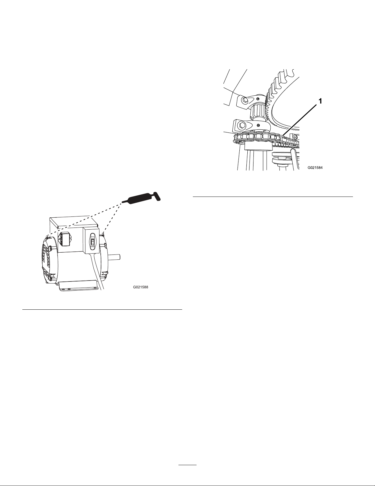
LubricatingtheMotorBearings
ServiceInterval:Every6,000hours
Greasetype:electric-motorbearinggrease
1.Cleanaroundeachgreasettingwitharag.
2.Pump1or2shotsofgreaseintoeachtting(Figure
33).
Important:Donotover-lubricatethemotor.
LubricatingtheDriveChain
ServiceInterval:Every40hours—Lubricatethedrivechain
withanon-stickychainlubricant.
Applyachainlubricantthatisnon-stickytohelppreventdirt
andabrasiveparticlesfromstickingtothechain.
Figure34
1.Drivechain
Figure33
3.Wipeupanyexcessgrease.
24
Page 25
ElectricalSystem
A
B
C
E
F
G020829
A
B
C
E
F
G020830
Maintenance
2.Removethelens(Figure36).
3.Pullthebulboutofthesocket(Figure36).
4.Pushanew168bulbintothesocket(Figure36).
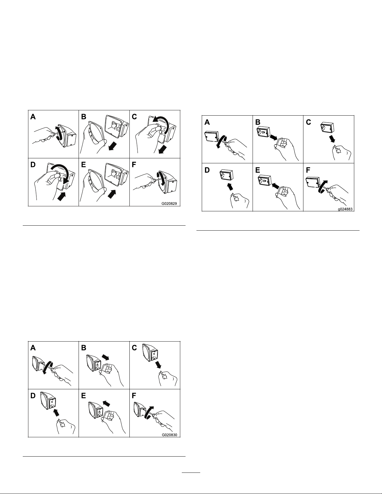
ReplacingtheRear-Facing SideBulbs
Note:Theleft,rear-facingbulbalsoilluminateslicenseplate.
1.Useascrewdrivertoremovethe4screwsfromthe
largesquarelensonthelight(Figure35).
Figure35
5.Installthelensandthe2screws(Figure36).
ReplacingtheFrontAmber Bulbs
1.Usingascrewdriver,removethe2screwsfromthe
amberlensonthefrontofthelight(Figure37).
Figure37
2.Removethelens(Figure35).
3.Pushandtwistthebulbcounterclockwisetoremoveit
fromthesocket(Figure35).
4.Pushanew1157bulbintothesocketandthentwistit
clockwise(Figure35).
5.Installthelensandthe4screws(Figure35).
ReplacingtheSide-Facing Bulbs
1.Useascrewdrivertoremovethe2screwsfromthelens
onthesideofthelight(Figure36).
2.Removetheamberlens(Figure37).
3.Pullthebulboutofthesocket(Figure37).
4.Insertanew193bulbintothesocket(Figure37).
5.Installtheamberlensandthe2screws(Figure37).
Figure36
25
Page 26
BeltMaintenance
G019976
1
2
3
1
1
g020662
A.MovetheclutchlevertotheOFFposition;refer
toControllingthePaddles(page19).
ServicingtheBelts
InspectingtheBelts
ServiceInterval:Aftertherst25hours—Inspectthebelts
andadjustasnecessary.
Every40hours—Inspectthebeltsandadjustas
necessary.
1.Removethedividerplate;refertoRemovingthe
DividerPlate(page22).
2.MovetheclutchlevertotheOFFposition;referto
ControllingthePaddles(page19).
3.Examinethebeltsforwearordamage.Ifthebeltsare
wornordamaged,replacethem;refertoReplacingthe
Belts(page27).
4.Examinethepulleysforwear,damage,and
misalignment;refertoAligningthePulleys(page29).
5.Installthedividerplate;refertoInstallingtheDivider
Plate(page23).
AdjustingtheBeltT ension
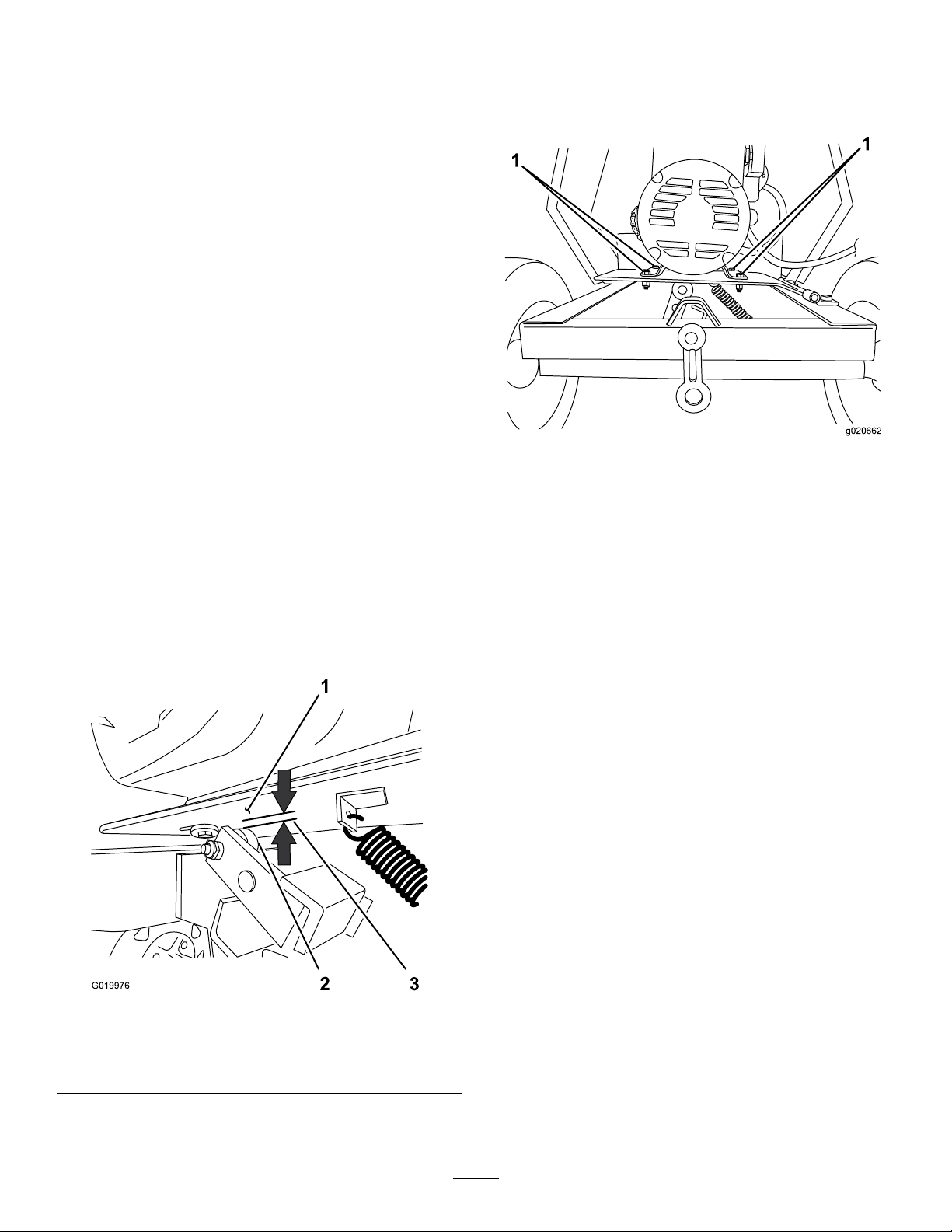
Clutchairgap:2.5to6.5mm(3/32to1/4inch)
1.MovetheclutchlevertotheONposition;referto
ControllingthePaddles(page19).
2.Measuretheairgapbetweenthemotordeckandthe
rollerontheclutch(Figure38).
B.Loosenthenutsandboltsthatsecurethemotor
tothemotordeck(Figure39).
Figure39
1.Nutandbolt
C.Movethemotorpositionasfollows:
•Increasetheairgap—movethemotoraway
fromtheidlerpulley(Figure39).
•Decreasetheairgap—movethemotor
towardtheidlerpulley(Figure39).
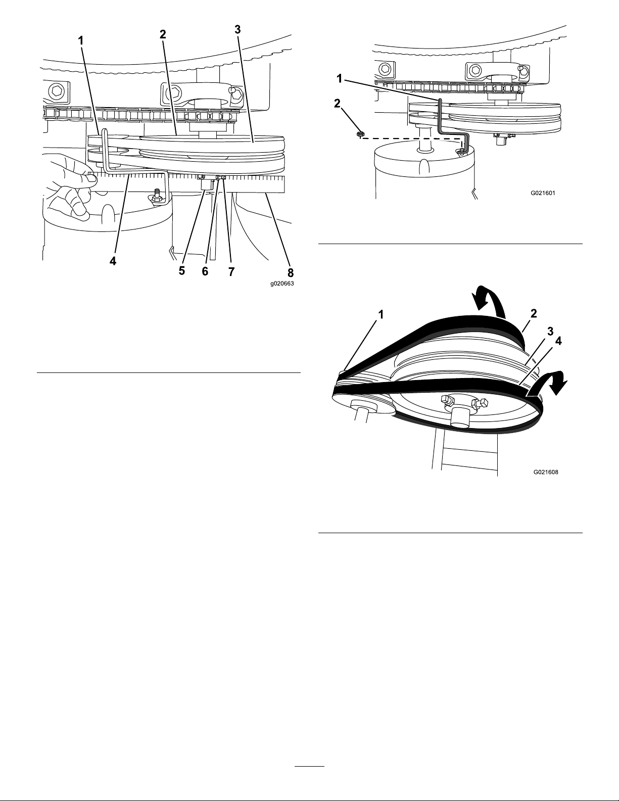
D.Alignastraightedgeacrossthemotorpulleyand
theidlerpulley(Figure40).
Figure38
1.Motordeck
2.Clutchroller
3.Ifthemeasuredairgapisnotwithinthespecied
range,adjustthegapasfollows:
3.Clutchairgap:2.5to6.5
mm(3/32to1/4inch)
26
Page 27
3
1
2
4
5
6
7
8
g020663
Figure40
2
1
G021601
2
3
4
1
G021608
Figure41
1.Nut2.Beltguide
4.Sliptheforwardbeltforwardandofftheidlerpulley
(Figure42).
1.Motorpulley
2.Idlerpulley6.Jamnut
3.Belt
4.Beltguide
5.Idlershaft
7.Setscrew
8.Straightedge
E.Ifneeded,pivotthemotoronthemotordeck
untilthemotorpulleyandtheidlerpulleyare
alignedtothestraightedge(Figure40).
F.Tightenthenutsandboltsthatsecurethemotor
tothemotordecktoatorqueof18N-m(13ft-lb).
G.Checktheairgapbetweenthemotordeckand
therollerontheclutch.Iftheairgapisnotwithin
thespeciedrange,repeatstep3untiltheairgap
measurementiswithinthespeciedrange.
H.Installthedividerplate;refertoInstallingthe
DividerPlate(page23).
Important:Ensurethatthepaddlesdonotrotatewhen
theclutchleverisintheOFFposition.
ReplacingtheBelts
Figure42
1.Motorpulley3.Idlerpulley
2.Forwardbelt4.Rearbelt
5.Sliptherearbeltrearwardandofftheidlerpulley
(Figure42).
6.Slipthebeltsoffthemotorpulley.
7.Removethebeltsfromthemachine.
ServiceInterval:Every2years—Replacethebelts.
RemovingtheBelts
1.MovetheclutchlevertotheOFFposition;referto
ControllingthePaddles(page19).
2.Removethedividerplate;refertoRemovingthe
DividerPlate(page22).
3.Removethenutthatsecuresthebeltguidetothe
motor,andremovethebeltguide(Figure41).
27
Page 28
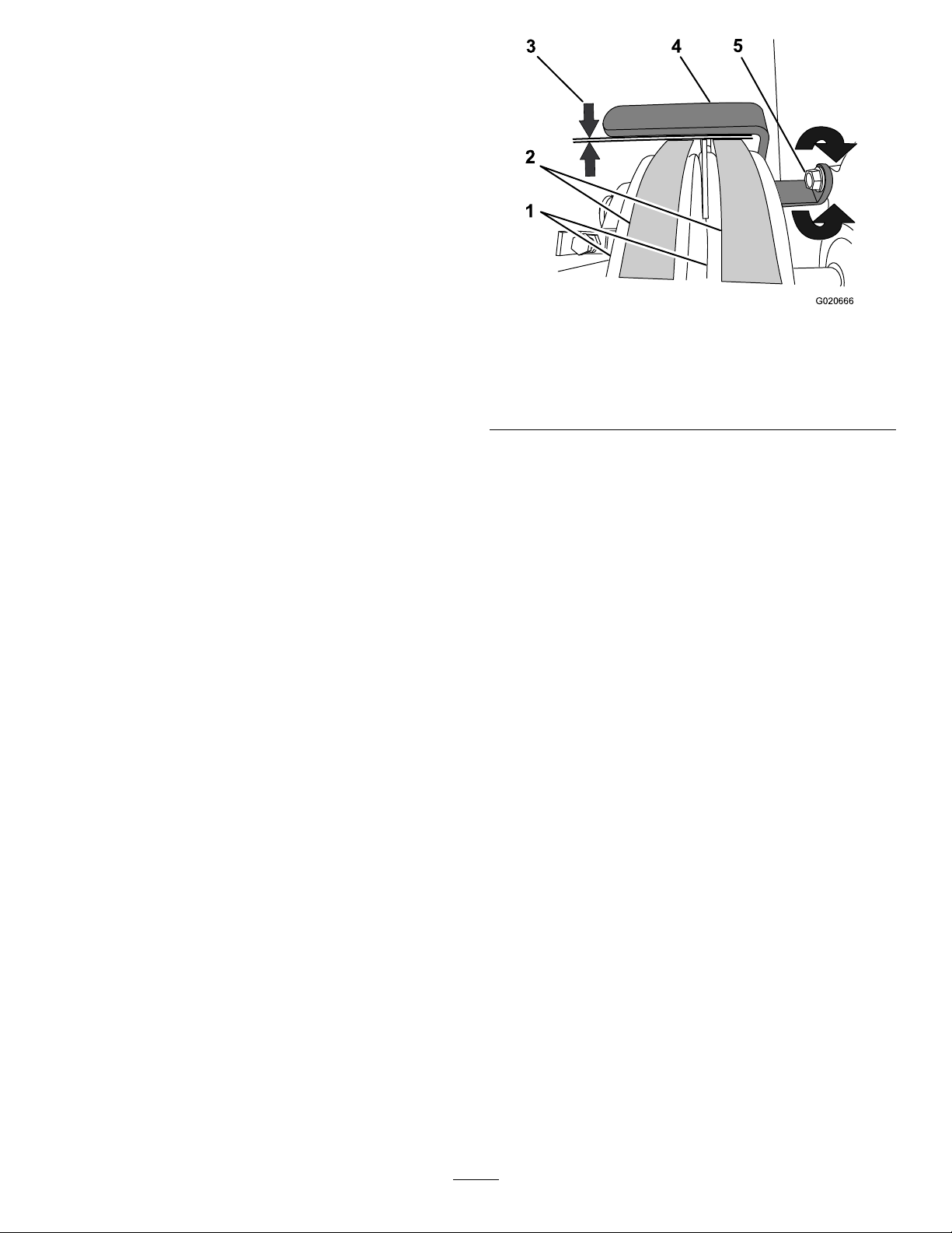
InstallingtheBelts
G020666
3 4
5
1
2
1.EnsurethattheclutchleverisintheOFFposition;
refertoControllingthePaddles(page19).
2.Aligntherearbelttothereargrooveinthemotor
pulley.
Note:Donotaligntherearbelttotheidlerpulley .
3.Aligntheforwardbelttotheforwardgrooveofthe
idlerpulley.
4.Sliptherearbeltovertheidlerpulleyandalignthebelt
totherearpulleygroove.
5.Sliptheforwardbeltoverthemotorpulleyandalign
thebelttotheforwardpulleygroove.
6.Checkthebelttension;refertostep1,step2,andstep
3inAdjustingtheBeltTension(page26).
7.Looselysecurethebeltguidetothemotor(Figure41)
withtheboltthatwasremovedinstep3ofRemoving
theBelts(page27).
Figure43
1.Motorpulleys4.Beltguide
2.Belts5.Nut
3.Guideairgap:2.5to4.0
mm(3/32to5/32inch)
8.Adjustthebeltguide;refertoAdjustingtheBeltGuide
(page28).
9.Installthedividerplate;refertoInstallingtheDivider
Plate(page23).
AdjustingtheBeltGuide
Note:Toaccessthebeltguide,removethedividerplate;
refertoRemovingtheDividerPlate(page22).
Guideairgap:2.5to4.0mm(3/32to5/32inch)
1.EnsurethattheclutchleverisintheONposition;refer
toControllingthePaddles(page19).
2.Ensurethatthebelttensioniscorrect;referto
AdjustingtheBeltTension(page26).
3.Checkthattheairgapbetweenthebeltguideandthe
beltsis2.5to4.0mm(3/32to5/32inch);referto
Figure43.
4.Iftheairgapisnotwithinthespeciedrange,dothe
following:
A.Loosenthenutthatsecuresthebeltguidetothe
motor(Figure43).
Important:Ensurethatthebeltguideis
towardthemotorpulley.
B.Rotatethebeltguideupordownuntilthereis
anairgapof2.5to4.0mm(3/32to5/32inch)
betweentheguideandeachbelt(Figure43).
Important:Thebeltguideshouldnot
contactthebeltswiththeclutchleverinthe
ONposition.
Note:Iftheairgapbetweenthebeltguideand
bothbeltscannotbeattained,then1ofthebelts
istoolong.
C.Tightenthenutthatsecuresthebeltguidetothe
motor(Figure43).
D.Checktheclutchoperation;refertoCheckingthe
ClutchOperation(page29).
5.Installthedividerplate;refertoInstallingtheDivider
Plate(page23).
28
Page 29
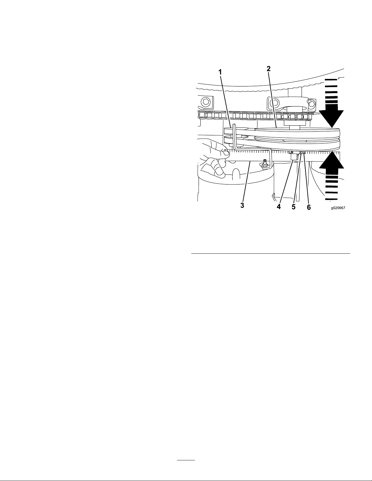
CheckingtheClutchOperation
1
2
3
4
5
6
g020667
AligningthePulleys
ServiceInterval:Every40hours—Checktheclutch
operation.
Important:Thepaddlesmustnotrotateinanempty
drumwhentheclutchleverisintheOFFposition.
1.MovetheclutchlevertotheOFFposition;referto
ControllingthePaddles(page19).
2.Startthemotor;refertoStartingtheMotor(page19).
3.IfthepaddlesrotatewiththeclutchlevertotheOFF
positiondothefollowing:
A.Stopthemotor;refertoStoppingtheMotor
(page19).
B.Checktheairgapbetweenthebeltguideandthe
belts.
Note:Iftheairgapislargerthan4.0mm(5/32
inch),decreasethegapbetweenthebeltguide
andthebelts;refertoAdjustingtheBeltGuide
(page28).
4.Repeatsteps1,2,and3untilthefollowingconditions
aremet:
•TheclutchleverisintheOFFposition.
•Whilethemotorisrunning,thepaddlesdonot
rotateinanemptydrum.
1.Removethedividerplate;refertoRemovingthe
DividerPlate(page22).
2.Placeastraightedgeacrossthefaceofthemotorpulley
andtheidlerpulley(Figure44).
Figure44
1.Motorpulley
2.Idlerpulley5.Locknut
3.Straightedge6.Setscrew
4.Idlershaft
Note:Bothpulleysmustbealignedushwiththe
straightedge.
3.Ifthepulleysarenotaligneddothefollowing:
A.MovetheclutchlevertotheOFFposition.
B.Loosenthelocknutsandsetscrewsthatsecurethe
idlerpulleytotheidlershaft(Figure44).
C.Usingasoft-facemallet,taptheidlerpulley
forwardorbackwardalongtheidlershaftuntil
4.Installthedividerplate;refertoInstallingtheDivider
themotorpulleyandtheidlerpulleyarealigned
tothestraightedge(Figure44).
D.Tightenthesetscrewsandlocknutsthatsecurethe
idlerpulleytotheidlershaft(Figure44).
Plate(page23).
29
Page 30
DriveChainMaintenance
G021606
1
G021602
1
2
3
4
1
2
G021605
CheckingandAdjustingthe DriveChain
ServiceInterval:Aftertherst10hours
Every50hours
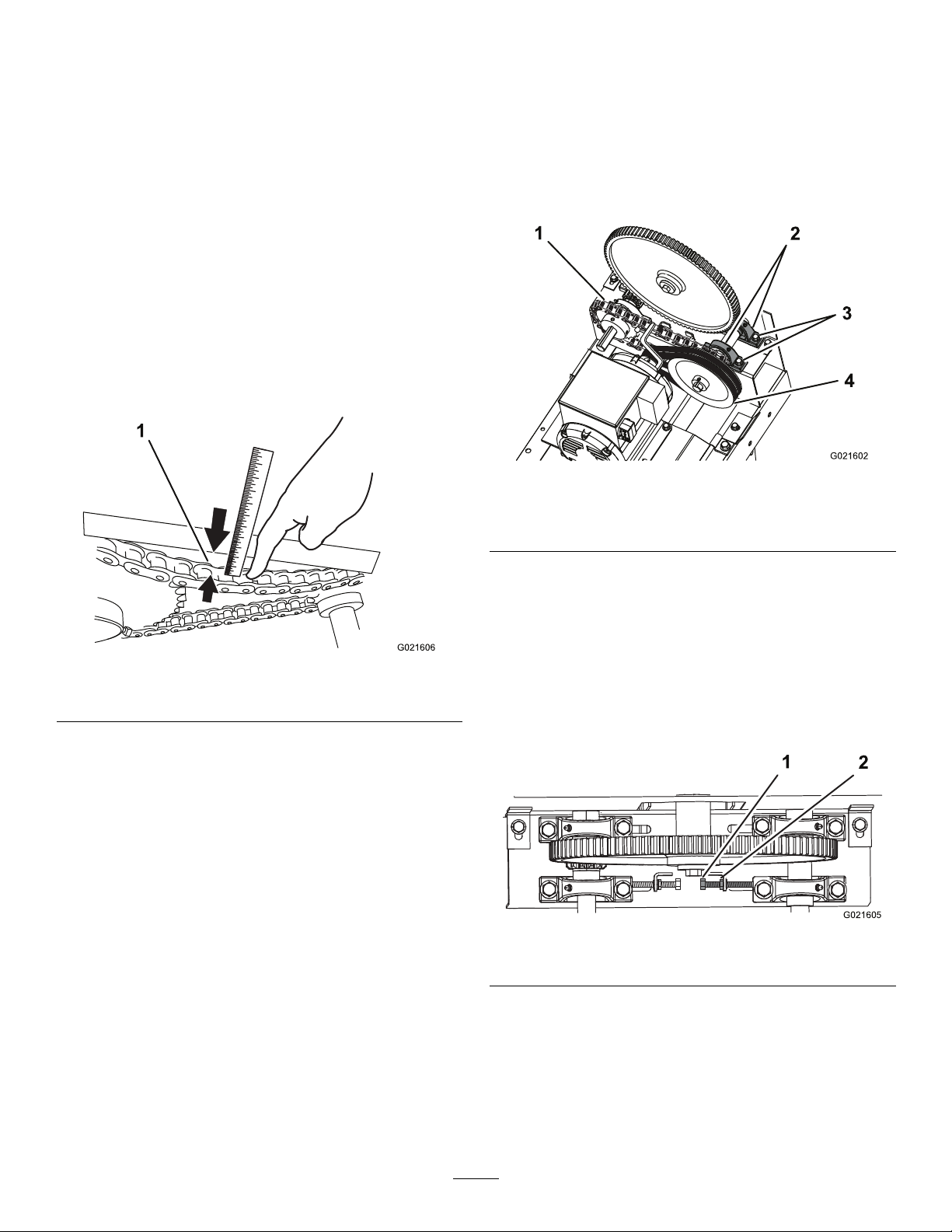
Thedrivechainshouldhave5to10mm(7/32to13/32inch)
ofexwhenapplying6.8kg(15lb)ofpressureatmid-span.
CheckingtheDrive-ChainTension
1.Removethedividerplate;refertoRemovingthe
DividerPlate(page22).
2.Placeastraightedgealongthechainfrom1sprocket
totheother(Figure45).
AdjustingtheDrive-ChainTension
Note:Adjustingthetensionofthedrivechainaffectsthe
tensionofthebelts;adjustthebelttensionafteradjusting
thedrive-chaintension.
1.Removethedividerplate;refertoRemovingthe
DividerPlate(page22).
2.Loosenthenutsandboltsthatsecurethepillow-block
bearingsfortheidlerpulley(Figure46).
Figure46
Figure45
1.Flexof5to10mm(7/32to13/32inch)
3.Withyournger,pushonthechainwith6.8kg(15lb)
ofpressure,midwaybetweenthesprockets(Figure45).
4.Measurethedistancefromthechaintothestraightedge;
thedistanceshouldbe5to10mm(7/32to13/32
inch).Ifthechaintensionneedsadjustment,referto
AdjustingtheDrive-ChainTension(page30).
5.Installthedividerplate;refertoInstallingtheDivider
Plate(page23).
1.Drivechain
2.Pillow-blockbearings4.Idlerpulley
3.Slidethepillow-blockbearings,alongwiththeidler
pulleyandsmallsprocket,totherighttoincrease
thechaintension,ortothelefttodecreasethechain
tension.
Note:Toslidethepillow-blockbearingstotheleft,
youmustloosenthejamnutandtensionerbolt(Figure
47).Toslidethepillow-blockbearingstotheright,
youmustloosenthemotormountingnutsandbolts
(Figure39).
3.Bolts(4)
Figure47
1.Tensionerbolt2.Jamnut
4.Whenthechainhas5to10mm(7/32to13/32inch)
ofex,tightenthetensionerbolt,thejamnut,andthe
nutsandboltsthatsecurethepillow-blockbearings.
5.Adjustthebelttension;refertoAdjustingtheBelt
Tension(page26).
6.Installthedividerplate;refertoInstallingtheDivider
Plate(page23).
30
Page 31
PaddleMaintenance
Note:Overtime,youmayneedtoadjustthemixerpaddles
toaccountforwear.
AdjustingthePaddles
AligningtheCircumferentialDrum
Wipers
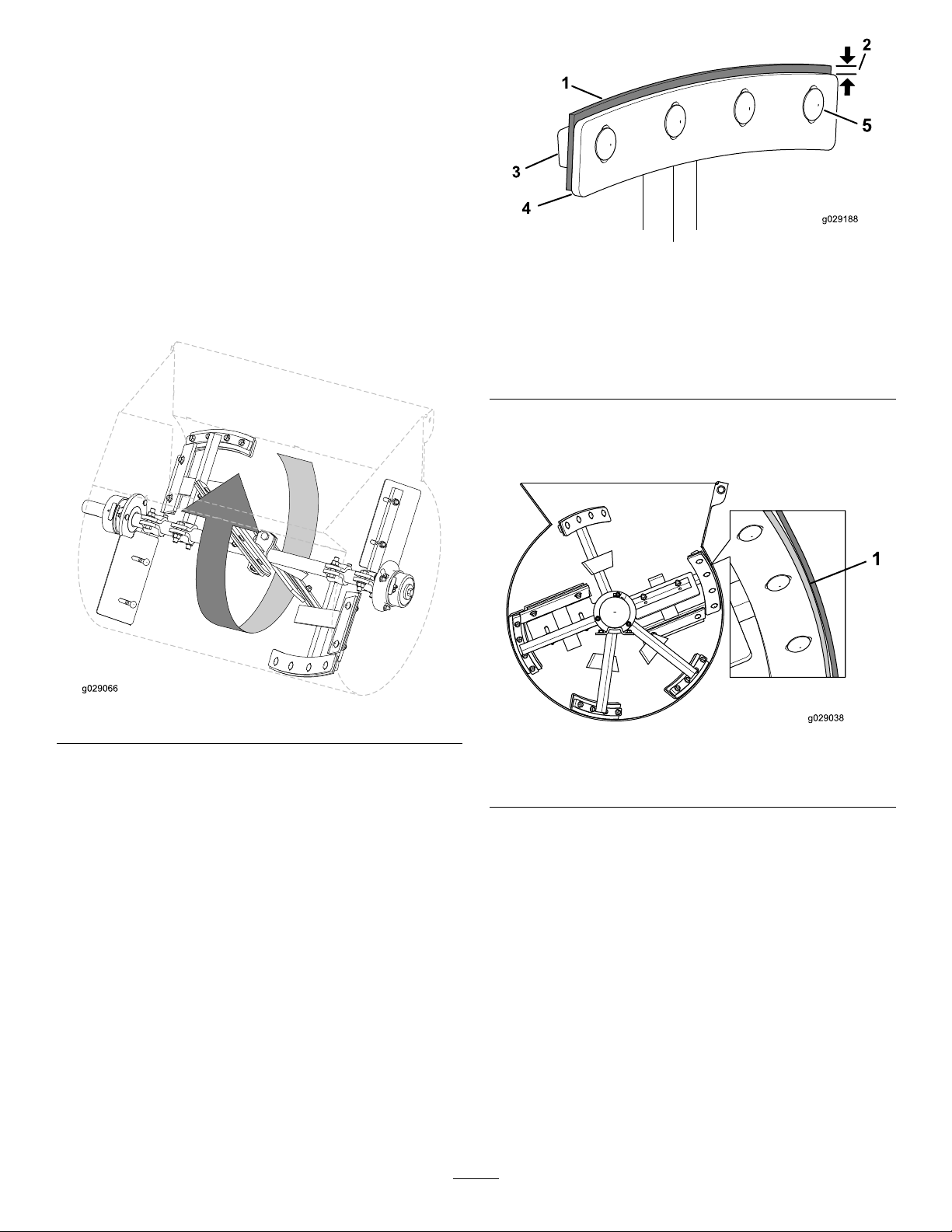
1.Rotateapaddlefromtheleftrowofpaddlesaround
thedrumandlocateattheinteriorofthedrumthe
smallestdistancebetweenthedrumandthewiperof
thepaddle(Figure48).
Figure49
1.Wiper4.Paddleblade
2.Distancebetween
paddle-bladeedgeand
wiperedge—3to6mm
(1/8to1/4inch)
3.Wiperbar
5.Adjustthepositionofthewipersothatthewiper
lightlycontactsthedrumacrossthelengthofthewiper
(Figure50).
5.Carriageboltandanged
locknut
Figure48
2.Marktheinsideoftheinsideofthedrumatthe
locationthatyoudeterminedinstep1.
3.Alignthewiperofapaddletothemark.
4.Loosenthecarriageboltsandangedlocknutsthat
securethepaddlebladeandwipertothepaddle(Figure
49).
Figure50
1.Wiperlightlycontactingthedrumatthesmallestdistance
betweenthedrumandthewiperofthepaddle
6.Adjustthepositionofthepaddlebladesothatthe
outeredgeis3to6mm(1/8to1/4inch)fromthe
outeredgeofthewiper.
7.Torquethecarriageboltsandnutsto19to25N-m
(14to18ft-lb).
8.Repeatsteps4through7fortheotherpaddleforthat
paddlerow .
9.Repeattheprocedurefortheotherpaddlerows.
31
Page 32
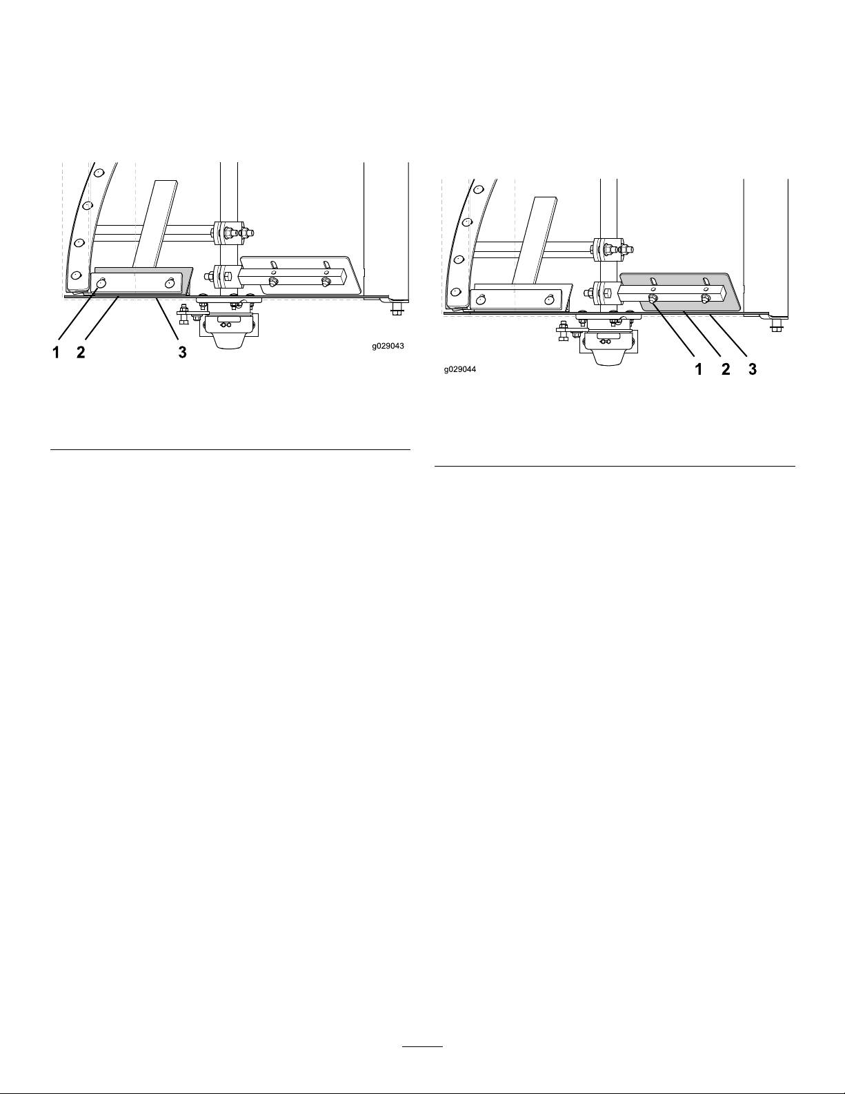
AligningtheEndPaddleWipers
AligningtheAdjustableEndPaddles
1.Rotatethewiperandxedpaddlearoundtheendplate
ofthedrumandlocatesmallestdistancebetweenthe
drumandthewiperofthepaddle.
2.Marktheinsideoftheendplateatthelocationthatyou
determinedinstep1.
Figure51
1.Carriageboltandanged
locknut
2.Closestpointofcontact
3.Drumendplate
1.Aligntheadjustableendpaddletothemarkthatyou
madeinstep2ofAligningtheEndPaddleWipers
(page32).
2.Loosenthecarriageboltsandangedlocknutsthat
securetheadjustableendpaddletothexedpaddle
(Figure52).
Figure52
1.Carriageboltandanged
locknut
2.Closestpointofcontact
3.Drumendplate
3.Alignthewiperofapaddletothemark.
4.Loosenthecarriageboltsandangedlocknutsthat
securethepaddlebladeandwipertothexedpaddle.
(Figure51)
5.Adjustthepositionofthewipersothatthewiperlightly
contactstheendplateacrossthelengthofthewiper.
6.Adjustthepositionofthepaddlebladesothatthe
outeredgeis3to6mm(1/8to1/4inch)fromthe
outeredgeofthewiper.
7.Torquethecarriageboltsandnutsto19to25N-m
(14to18ft-lb).
8.Repeattheprocedureforthewiperattheendplateon
theotherendofthedrum.
3.Adjustthepositionoftheadjustableendpaddlesothat
itisasclosetotheendplateaspossible,acrossthe
lengthofthepaddle,withouttouchingendplatewhen
thepaddlesarerotated.
4.Torquethecarriageboltsandnutsto37to45N-m
(27to33ft-lb).
5.Repeattheprocedurefortheadjustableendpaddleat
theendplateontheotherendofthedrum.
32
Page 33

Cleaning
Storage
CleaningtheMachine
Regularcleaningandwashingincreasesthelifespanofthe
machine.Cleanthemachineaftereachuse,beforethedirt
hardens.
Ensurethatthemotorisunplugged.
Usecarewhenusingahigh-pressuresprayerbecauseitcan
damagewarningdecals,instructionsigns,andthemotor.
Important:Usepressuresprayerstocleanonlythe
drumofthemachine.Cleanofftherestofthemachine
byhandtokeepthemotorfromgettingwet.
Important:Lubricatethetrunnionsaftercleaning;refer
toLubricatingtheBearingsandSeals(page23).
StoringtheMachine
Forstorageover30days,preparethemachineasfollows:
1.MovetheON/OFFswitchtotheOFFposition,and
unplugthepowercord.
2.Removedirtandgrimefromtheexternalpartsofthe
entiremachine,especiallythemotor.
Important:Youcanwashthemachinewithmild
detergentandwater.
3.Greasethemachine;refertoLubricatingtheBearings
andSeals(page23)andLubricatingtheDriveChain
(page24).
4.Checkandtightenallbolts,nuts,andscrews.Repairor
replaceanypartthatisdamaged.
5.Paintallscratchedorbaremetalsurfaceswithpaint
fromyourAuthorizedToroDealer.
6.Storethemachineinaclean,drygarageorstoragearea.
7.Coverthemachinetoprotectitandkeepitclean.
33
Page 34

Troubleshooting
Problem
Theelectricmotordoesnotstart.
Themachineishummingexcessively.1.Thecordispluggedintoanincorrect
Themotorisoverheating.
1.Theconnectorforthemachineisnot
pluggedintoapowersource.
2.Thethermal-overloadprotectionforthe
motorsisactivated.
3.Thecurrentprotectorfortheelectrical
sourceisopen.
4.Themachineispluggedintoan
electricalsourcelessthan1 15voltsor
greaterthan230volts.
5.Thepaddlesarejammedinsidethe
drum.
outlet.
1.Themotorisoverloaded.
2.Thereisnotadequateventilation.
3.Themotorisrunningovervoltageor
undervoltage.
PossibleCauseCorrectiveAction
1.Plugtheconnectorintoasocketor
anextensioncordfromanelectrical
source.
2.Resetthethermal-overloadprotector.
3.Resetthecircuitprotector.
4.Connectthemachinetoanelectrical
sourcewiththepropervoltage.
5.Disconnectthemachinefromthe
electricalsource,movetheclutchto
theoffposition,andclearthedebris
fromtheinsideofthedrum.
1.Checktheinputlineconnections.
1.Comparetheactualamps(measured)
withtheratingonthenameplate.
Locateandremovethesourceof
excessivefrictioninthemotororload.
Reducetheload.
2.Checktheexternalcoolingnsfor
excessivedirtbuildupandcleanthe
motor.
3.Checktheinputvoltagetothemotor.
Thebeltslipsorcomesoffthepulleys.
isintheOFFposition.
leverisintheONposition.
Thepaddlesrotateslowlywhentheclutch
leverisintheONposition.
Themixermakesachirpingnoisewhen
mixingmaterial.
1.Thebelttensionisinsufcient.
2.Thebeltisworn.2.Replacethebelt.
3.Thepulley(s)areworn.3.ContactyourAuthorizedService
4.Thepulley(s)aremisaligned.4.Alignthepulley(s).
1.Theclutchleverisnotadjusted
correctly.
2.Thebeltguideisnotadjustedcorrectly.2.Adjustthebeltguide.
1.Theclutchleverisnotadjusted
correctly.
2.Thepaddlesarestuckinthedrum.
1.Theclutchleverisnotadjusted
correctly.
1.Thedrivegearismisalignedwiththe
bullgear .
1.Adjustthebelttension.
Dealer.
1.Adjustthebelttension. Thepaddlesrotatewhentheclutchlever
1.Adjustthebelttension. Thepaddlesdonotrotatewhentheclutch
2.Cleanthepaddlesanddrum.
1.Adjustthebelttension.
1.ContactyourAuthorizedService
Dealer.
34
Page 35
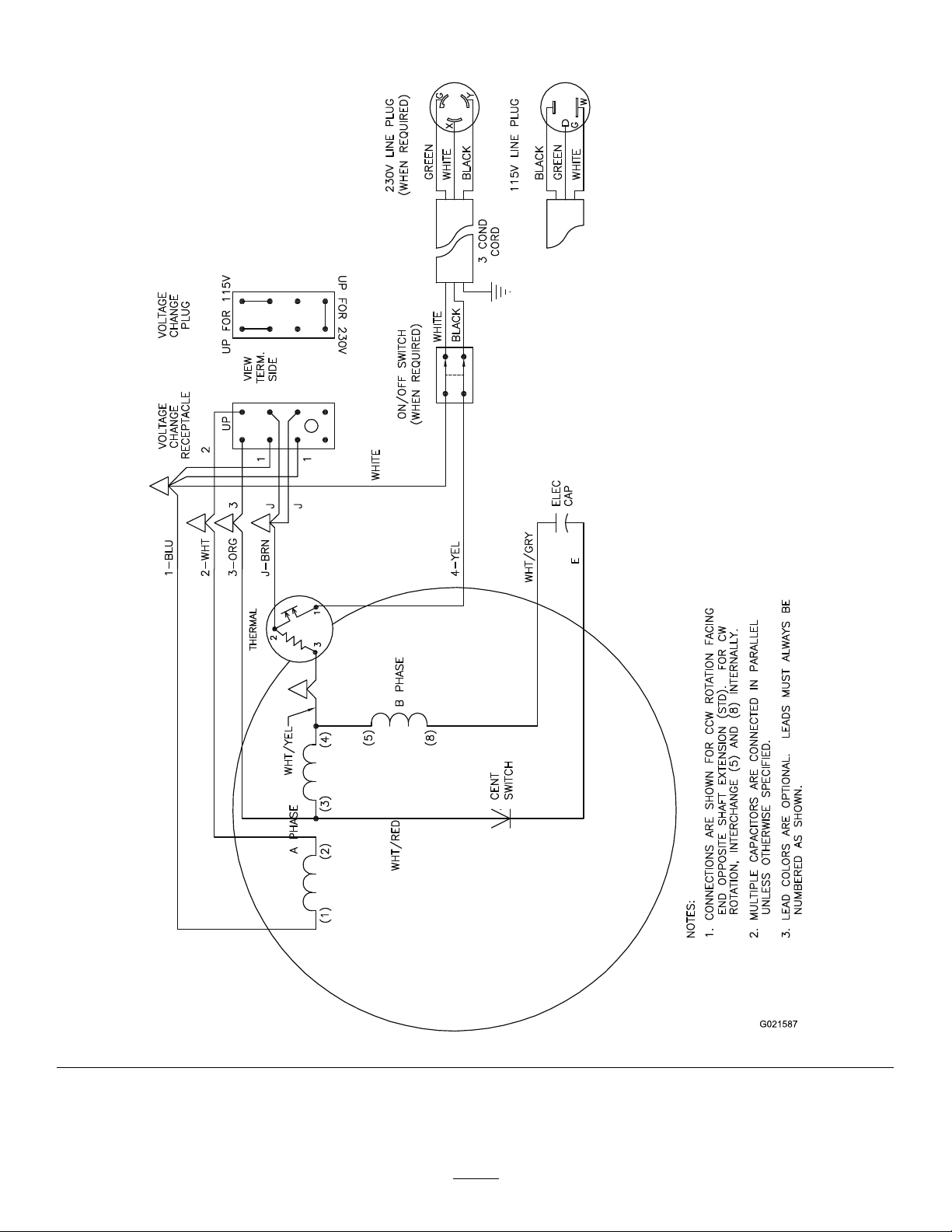
Schematics
G021587
ElectricMotorSchematic(Rev.A)
35
Page 36

Alimitedwarranty(seewarrantyperiodsbelow)
TheToroWarranty
Concrete,
Masonry,and
Compaction
Equipment
ConditionsandProductsCovered
TheT oroCompanyanditsafliate,ToroWarrantyCompany ,pursuantto
anagreementbetweenthem,jointlywarrantyourT oroConcrete,Masonry,
andCompactionEquipmentProductslistedbelowtobefreefromdefectsin
materialsorworkmanship.
Thiswarrantycoversthecostofpartsandlabor,butyoumustpay
transportationcosts.
Thefollowingtimeperiodsapplyfromthedateofpurchase:
ProductsWarrantyPeriod
ConcreteMixers
•SpindleBearingsLifetime*(originalowneronly)
MortarMixers1year
•DrumBearingsandSealsLifetime*(originalowneronly)
ForwardPlateCompactors
ReversiblePlates1year
RammerCompactors
MudBuggy1year
VibratingTrenchRoller2years
ConcreteSaws
MasonrySaws
PowerTrowels1year
Screeds
ConcreteVibrators
Whereawarrantableconditionexists,wewillrepairtheProductatnocost
toyouincludingdiagnosis,labor,andparts.
*
LifetimeWarranty-Ifthebearing(s)orseal(s)onyourmixerfail,itwillbereplacedunderwarranty ,
atnocostforpartsorlabor.
1year
2years
2years
1year
1year
1year
1year
InstructionsforObtainingWarrantyService
IfyouthinkthatyourT oroProductcontainsadefectinmaterialsor
workmanship,followthisprocedure
1.ContactanyAuthorizedServicingOutlettoarrangeserviceattheir
dealership.T olocateoneconvenienttoyou,accessourwebsiteat
www.T oro.com.Select“WheretoBuy”andselect“Contractor”under
producttype.Y oumayalsocallourtollfreenumberbelow.
2.Bringtheproductandyourproofofpurchase(salesreceipt)tothem.
3.IfforanyreasonyouaredissatisedwiththeServiceOutlet’sanalysis
orwiththeassistanceprovided,contactusat:
SWSCustomerCareDepartment
ToroWarrantyCompany
811 1LyndaleAvenueSouth
Bloomington,MN55420-1196
TollFree:800-888-9926
**
ToroAuthorizedRentalCustomerswhohavepurchasedproductsdirectlyfromT oroandhave
signedtheT oroRentalCustomerAgreementhavetheabilitytoperformtheirownwarrantywork.
PleasevisitT oro’sRentalPortalforelectronicwarrantyclamlingproceduresorcallthetollfree
numberabove.
**
:
OwnerResponsibilities
YoumustmaintainyourT oroProductbyfollowingthemaintenance
proceduresdescribedintheOperator’sManual.Suchroutinemaintenance,
whetherperformedbyadealerorbyyou,isatyourexpense.Parts
scheduledforreplacementasrequiredmaintenance(“MaintenanceParts”),
arewarrantedfortheperiodoftimeuptothescheduledreplacementtime
forthatpart.Failuretoperformrequiredmaintenanceandadjustmentscan
begroundsfordisallowingawarrantyclaim.
ItemsandConditionsNotCovered
Notallproductfailuresormalfunctionsthatoccurduringthewarrantyperiod
aredefectsinmaterialsorworkmanship.Thisexpresswarrantydoesnot
coverthefollowing:
•Productfailureswhichresultfromtheuseofnon-T ororeplacement
parts,orfrominstallationanduseofadd-on,modied,orunapproved
accessories
•Productfailureswhichresultfromfailuretoperformrequired
maintenanceand/oradjustments
•ProductfailureswhichresultfromoperatingtheProductinanabusive,
negligentorrecklessmanner
•Partssubjecttoconsumptionthroughuseunlessfoundtobedefective.
Examplesofpartswhichareconsumed,orusedup,duringnormal
productoperationinclude,butarenotlimitedto,belts,wipers,spark
plugs,tires,lters,gaskets,wearplates,seals,O-rings,drivechains,
clutches.
•Failurescausedbyoutsideinuence.Itemsconsideredtobeoutside
inuenceinclude,butarenotlimitedto,weather,storagepractices,
contamination,useofunapprovedcoolants,lubricants,additives,or
chemicals,etc.
•Normal“wearandtear”items.Normal“wearandtear”includes,butis
notlimitedto,wornpaintedsurfaces,scratcheddecals,etc.
•Repairsnecessaryduetofailuretofollowrecommendedfuel
procedure(consultOperator'sManualformoredetails)
–Removingcontaminantsfromthefuelsystemisnotcovered
–Useofoldfuel(morethanonemonthold)orfuelwhichcontains
morethan10%ethanolormorethat15%MTBE
–Failuretodrainthefuelsystempriortoanyperiodofnon-use
overonemonth
•Anycomponentcoveredbyaseparatemanufacturer’swarranty
•Pickupanddeliverycharges
GeneralConditions
RepairbyanAuthorizedServicingOutletorSelf-ServiceasanAuthorized
RentalCustomerisyoursoleremedyunderthewarranty.
NeitherTheToroCompanynorToroWarrantyCompanyisliablefor
indirect,incidentalorconsequentialdamagesinconnectionwiththe
useoftheToroProductscoveredbythiswarranty,includingany
costorexpenseofprovidingsubstituteequipmentorserviceduring
reasonableperiodsofmalfunctionornon-usependingcompletionof
repairsunderthiswarranty .Allimpliedwarrantiesofmerchantability
andtnessforusearelimitedtothedurationofthisexpresswarranty.
Somestatesdonotallowexclusionsofincidentalorconsequential
damages,orlimitationsonhowlonganimpliedwarrantylasts,sothe
aboveexclusionsandlimitationsmaynotapplytoyou.
Thiswarrantygivesyouspeciclegalrights,andyoumayalsohaveother
rightswhichvaryfromstatetostate.
ExceptfortheenginewarrantycoverageandtheEmissionswarranty
referencedbelow,ifapplicable,thereisnootherexpresswarranty .The
EmissionsControlSystemonyourProductmaybecoveredbyaseparate
warrantymeetingrequirementsestablishedbytheU.S.Environmental
ProtectionAgency(EPA)ortheCaliforniaAirResourcesBoard(CARB).
RefertotheCaliforniaEmissionControlWarrantyStatementsuppliedwith
yourProductorcontainedintheenginemanufacturer’sdocumentationfor
details.
CountriesOtherthantheUnitedStatesorCanada
CustomerswhohavepurchasedT oroproductsoutsidetheUnitedStatesorCanadashouldcontacttheirToroDistributor(Dealer)toobtainguarantee
policiesforyourcountry,province,orstate.IfforanyreasonyouaredissatisedwithyourDistributor'sserviceorhavedifcultyobtainingguarantee
information,contacttheT oroimporter .Ifallotherremediesfail,youmaycontactusatT oroWarrantyCompany .
AustralianConsumerLaw:AustraliancustomerswillnddetailsrelatingtotheAustralianConsumerLaweitherinsidetheboxoratyourlocalT oro
Dealer.
374-0288RevC
 Loading...