How it Works
Log In / Sign Up
Buy Points
How it Works
FAQ
Contact Us
Questions and Suggestions
Users
Toro
Loading...
#
5300-D
5400-D
5410
5500D
5510
2
5510-D
5510-G
52653
52803
52804
52914
52918
52919
53002
4
53003
5
53008
2
53009
2
53010
6
53011
6
53020
4
53021
3
53030
3
53035
3
53040
2
53041
2
53047
3
53050
53051
53080
2
53085
53300
2
53380
53594
53595
53599
53707
53708
53709
2
53720
53721
53746
53749
2
53763
53764
2
53765 - Outdoor Ecxtra Sprinkler Timer
53769
53770
53794
53799
53803
53804
53805
53806
2
53812
2
53823
53851
53852
53853
2
53854
53855
53869
53877
53878
53879
53880
53881
53882
53883
53887
53892
53893
53898
53899
53900
53925
54610
39
55000
55001
55002
55003
55050
55051
55055
55101
55150
55152
55166
55200
55233
2
55256
2
55275
55301
54-9820
2
54-9821
2
54-9822
2
55-7390
55-7800
2
55-8110
2
55-8450
55-8460
2
Loading...
Loading...
Nothing found
53852
Users Manual
12 pgs
5.75 Mb
0
Table of contents
Loading...
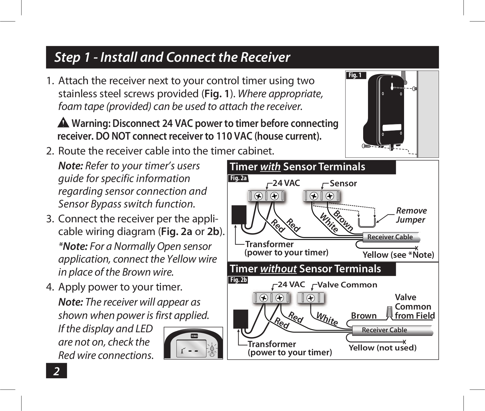
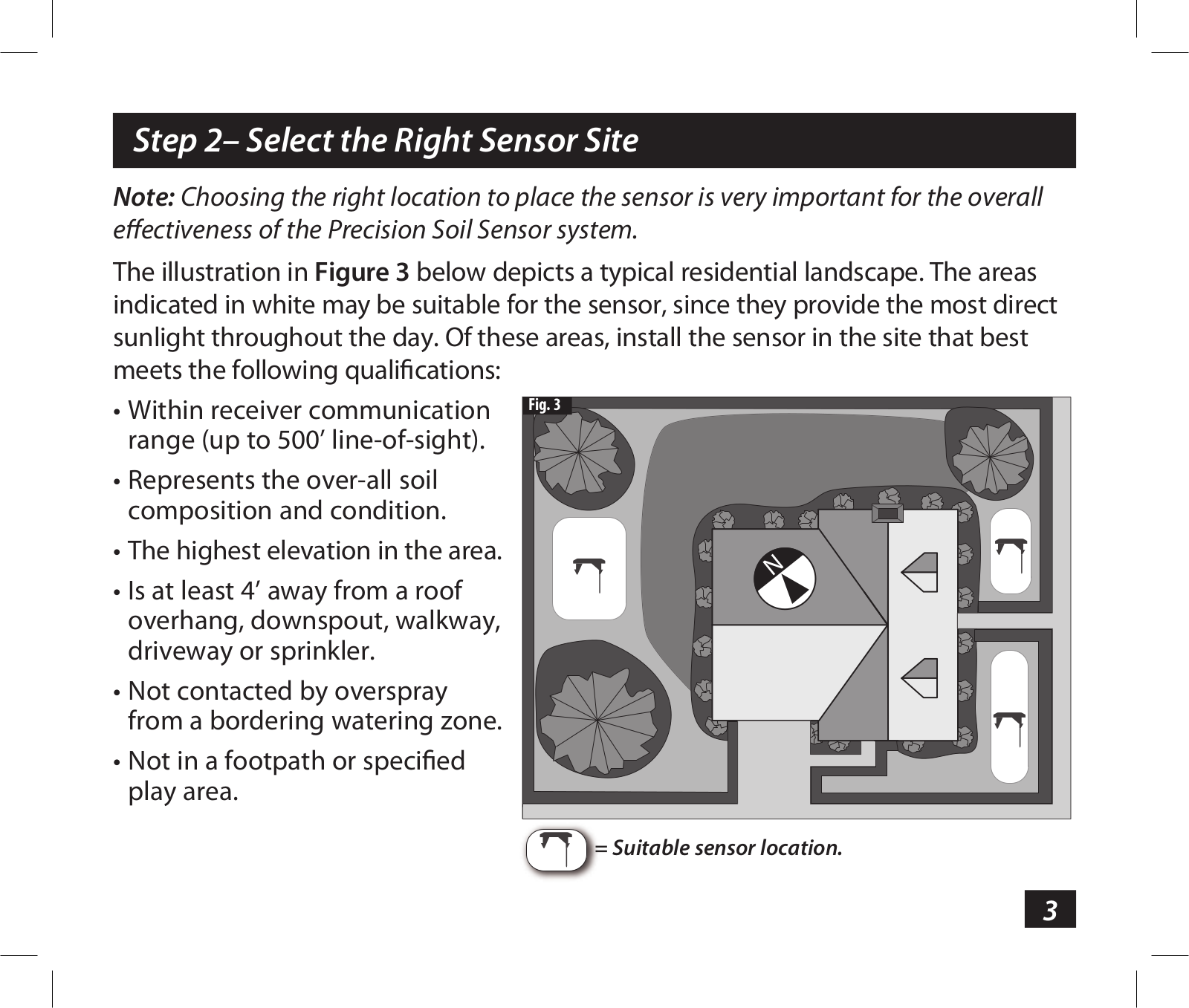
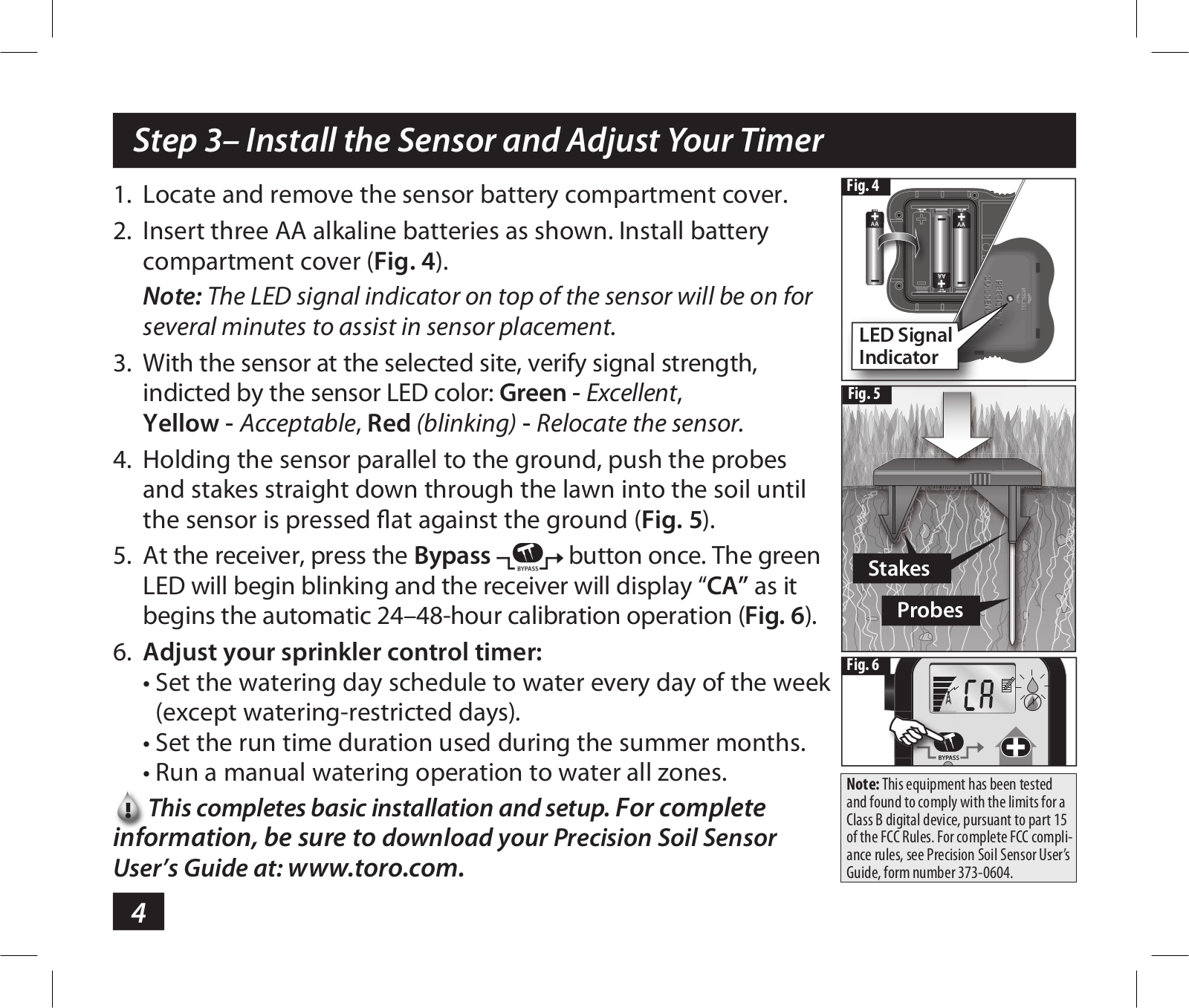
Toro 53852, 53851 Users Manual
...
Toro Users Manual
Download
Specifications and Main Features
Frequently Asked Questions
User Manual
Download
Loading...
+
8
hidden pages
Unhide
You need points to download manuals.
1 point = 1 manual.
You can buy points or you can get point for every manual you upload.
Buy points
Upload your manuals
 Loading...