

Toro 53765 - Outdoor Ecxtra Sprinkler Timer, Ecxtra User Manual
ECXTRA Features
• Easily expandable to 10 Zones (Indoor model)
or 12 Zones (Outdoor Model) with 2-zone
Plug-in Modules
• Snap-in Wire Connectors
• Compatible with ECXTRA Scheduling Advisor
TM
• 3 Independent Watering Programs with:
- Calendar, Interval and Odd/Even Days
- Selective Day Exclusion
- 1-minute to 4-hour Zone Run Time
- 4 Start Times
• Seasonal Run Time Adjust
• Rain Delay
• Compatible with Normally Closed or Normally
Open Rain Sensors
• Automatic 24V Circuit Protection
• Program Memory Backup without Battery
• Programmable Pump Start
B
C
A
MANUAL
START
ON
NEXT
OFF
MANUAL
START
ON
NEXT
OFF
Automatic Sprinkler
System Control Timer
User’s Guide
INDOOR MODEL
OUTDOOR MODEL


Timer Components ........................................2-5
Timer Installation
Indoor Model Installation ................................6
Connecting the Valves....................................7
Connecting a Pump Start Relay......................8
Connecting the Transformer ...........................8
Outdoor Model Installation .............................9
Preparing the Cabinet for Installation..............9
Installing the Cabinet.....................................10
Connecting the Valves..................................11
Connecting a Pump Start Relay....................12
Connecting the Power Source ......................13
Connecting a Rain Sensor...............................13
Getting Started
Sprinkler System Basics ..................................14
Watering Program Basics ................................15
Watering Program Details ..........................16-17
Planning Your Watering Schedule...................18
Filling Out the Watering Schedule Form.....18-19
Watering Schedule Form ..............................20
About the Timer Memory .................................21
Programming the Timer
Setting the Current Time, Day and Date..........21
Setting the Watering Day Schedule............22-24
Setting a Calendar Schedule ........................22
Setting an Interval Schedule.........................23
Setting an Odd or Even Schedule.................24
Using the Day Exclusion Feature .................25
Programming the Timer (continued)
Turning Off a Program ....................................26
Setting Program Start Times ...........................27
Setting Program Start Times ...........................27
Setting Zone Run Times .................................28
Pump Control ..................................................29
Timer Operations
Automatic Operation .....................................30
Manual Operation ..........................................31
Starting Programs or Zones Manually...........31
Watering Control Features............................32
To Pause Watering .....................................32
To Resume Watering..................................32
To Cancel Watering ....................................32
To Skip Zones.............................................32
To Adjust the Zone Run TIme.....................33
Using the Rain Delay Feature..........................33
Using the Season Adjust Feature ....................34
Turning Off the ECXTRA ................................35
Service and Specifications
Clearing the Program Memory.........................36
Automatic Circuit Protection ............................37
Adding a Zone Module.....................................37
Troubleshooting ...............................................38
Specifications...................................................39
Glossary of Terms.....................................39-41
Warranty.............................................................42
Electromagnetic Compatibility ................42
Table of Contents
1
Timer Components
Timer Components
2
SENSOR
24 VAC
MANUAL
START
ON
NEXT
OFF
BF

Timer Components
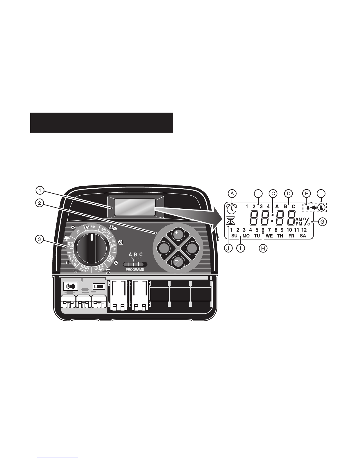
The following are brief descriptions of the timer
components and display elements. Each of these items
will be explained in further detail within the appropriate
programming, operating and installation sections of
this guide.
1 - LCD Display
A - “Start Time” symbol is displayed when setting the
program start times.
B - Program start time identification numbers 1–4.
C - Main display of various time values and prompts.
D - Program A, B and C identifiers.
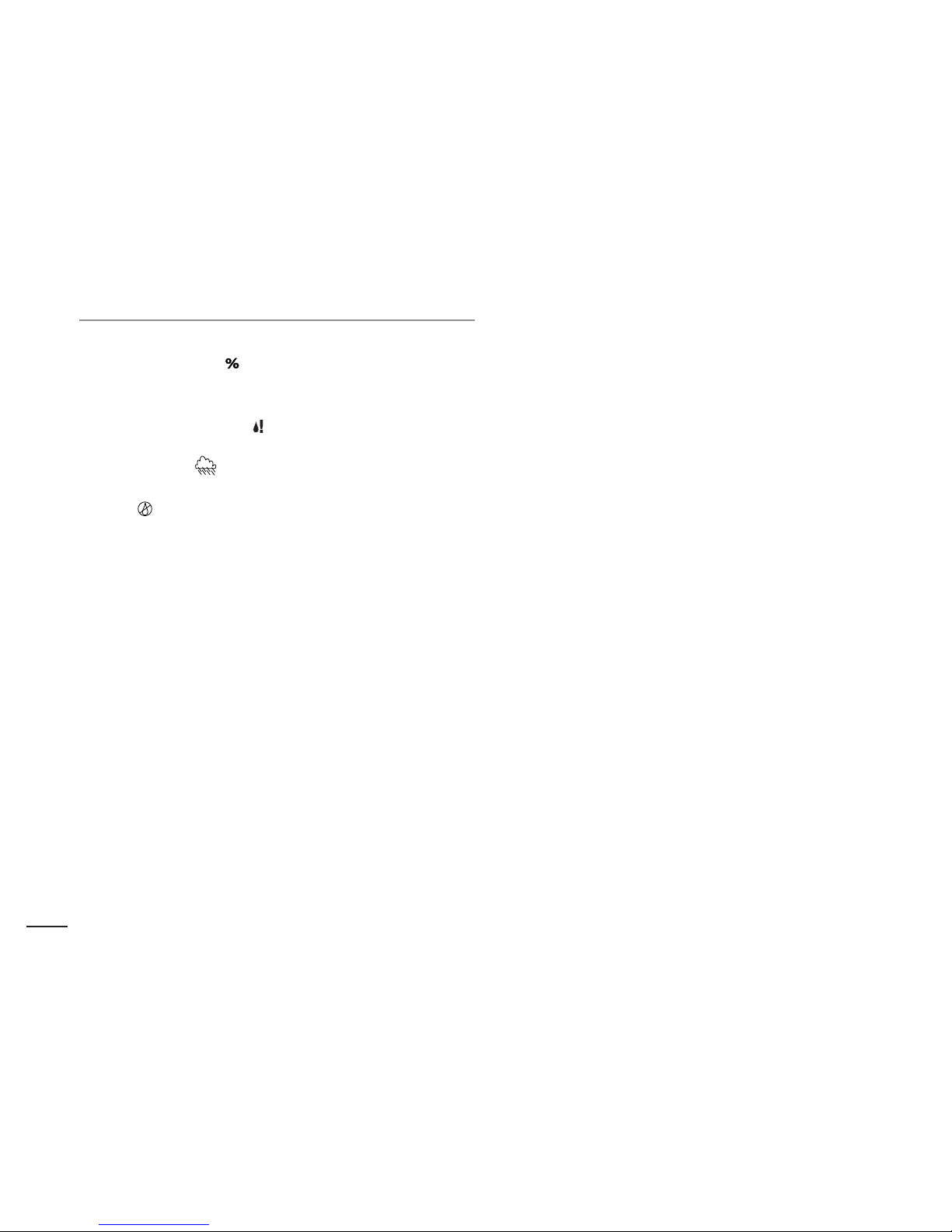
E - “Watering On” symbol is displayed when a
watering zone is running. Symbol blinks when
watering is paused.
F - “Watering Off” symbol is displayed when the
Rain Delay feature is active.
G - “Percent” symbol is displayed when the Season
Adjust feature is in use.
H - Watering zone identification numbers.
I - Day-of-the-week identifiers.
J - “Run Time” symbol is displayed when setting the
watering zone run times.
2 - Control Buttons
+/
ON button – Increases the time display, scrolls
forward through the program information and selects
watering days.
–/
OFF button – Decreases the time display, scrolls
backward through the program information and
removes watering days.
NEXT button – Advances to the next portion of
program information. Resumes watering if paused.
Advances through stations manually when watering.
MANUAL START button – Selects and starts manual
watering operations.
3 - Control Dial – Selects all controller programming
and operation controls (except Manual Start).
Control Dial Positions
RUN – The normal dial position for all automatic
and manual operations.
CURRENT TIME/DAY – Enables the clock time
and day to be set.
WATERING DAYS – Enables the watering day
schedules to be set and reviewed.
START TIMES – Enables the program start times to
be set and reviewed.
SET ZONE TIMES – Enables the watering zone run
time to be set and reviewed.
(continued)
3
Timer Components
3 - Control Dial Positions (continued)
SEASON ADJUST – Enables the run time of all
stations in a program to be simultaneously
increased or decreased in 10% increments.
SPECIAL FUNCTIONS – Provides optional control
and timing features for pump operation.
RAIN DELAY – Enables all watering operations to
be delayed from 1 to 7 days.
OFF – Shuts off and prevents all automatic and
manual watering activity.
4 - Program Select Switch – Three-position slide
switch used to select watering program A, B or C
during the programming procedures and manual
operation.
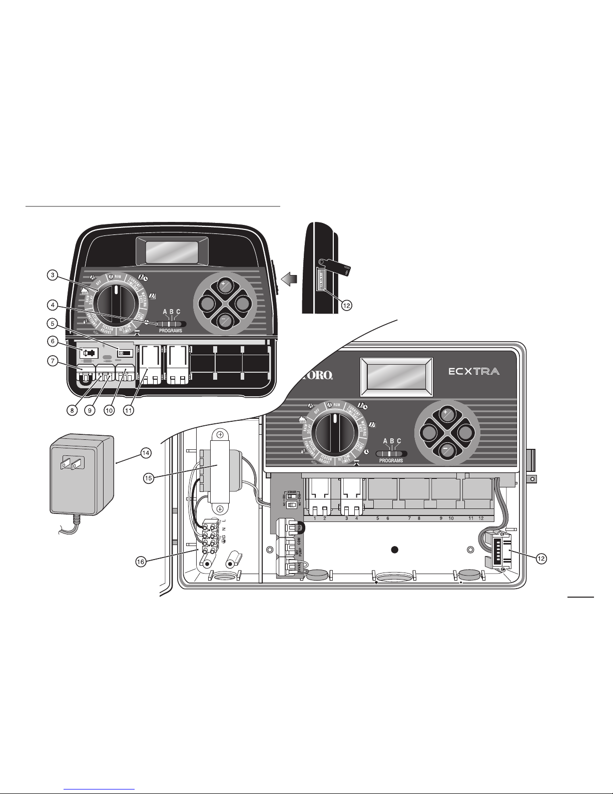
5 - Rain Sensor Control Switch – Controls the sensor
input circuit. Switch positions provided for sensor
circuit Enable and Disable (bypass).
6 - Rain Sensor Configuration Switch – Selects
either Normally Open or Normally Closed sensor
operation for the type of sensor installed.
7 - Sensor Connection Terminals – Snap-in wire
connector for (optional) Toro Rain Sensor.
8 - Valve Common Connection Terminal – Snap-in
wire connector for the valve common wire.
9- Pump/Master Valve Connection Terminal –
Snap-in wire connector for a pump start relay or
master valve.
10 - Transformer Connection Terminals – Snap-in
connectors for the plug-in transformer wires.
11 - Plug-In 2- Zone Module – Each plug-in module
provides snap-in connectors for two zone control
valve power wires. Up to six modules (12 zones)
can in the installed in the outdoor timer model and
five modules (10 zones) in the indoor model.
12 - Time Pod
TM
Port – Accepts the (optional) ECXTRA
Time Pod unit to transfer watering schedule data
from the Toro Computer Aided Scheduling software
program to the ECXTRA timer.
13 - Power Supply – A Plug-in transformer supplies
24 V a.c. power to the indoor controller models.
14 - Transformer – A built-in transformer supplies
24 V a.c. power to the outdoor controller models.
15 - Terminal Block – Connection terminals for
120 V a.c. power wires (Indoor model only).
4
5
B
C
A
MANUAL
START
ON
NEXT
OFF
SENSOR
24 VAC
MANUAL
START
ON
NEXT
OFF
Timer Components
Note: The ECXTRA indoor timer is not weather resistant and must be installed indoors or in a protected
area.
1. Select a location for the timer within 4' of an
electrical outlet to enable the transformer cord to
easily reach. Make sure the outlet is not controlled
by a light switch.
2. Remove the mounting bracket attached to the back
of the timer housing by pulling the lower edge of the
bracket away and downward from the timer housing.
3. Place the mounting bracket (A) against the wall aligning the top edge at about eye level. Drive three 1"
wood screws (B) into the wall through the three holes
provided in the bracket.
Note: If you are installing the bracket on drywall or
masonry, install screw anchors (C) to prevent screws
from loosening.
4. Optional - Insert 3/4" PVC conduit (D) for valve
wiring into bracket sleeve (E).
5. Align the slotted openings on the back of timer housing with the mounting bracket tabs. Slide the timer
downward to engage the tabs.
Note: After installation, store the Quick Reference
Guide and the Watering Schedule Form in the
pocket (F) behind the timer.
Indoor Model Installation
Timer Installation
6
B
C
F
A
E
D
1. Route the valve control wires between the valves and
the timer.
Note: The snap-in wire connectors accept 14 to 18
gauge wire. Using 18-gauge, multi-strand, direct-burial
irrigation cable is recommended. Choose a cable that
has at least one more wire conductor than the number
of valves to be connected.
2. Attach the white color-coded wire to either
one of the
wires from each valve solenoid. This is called the
valve common wire.
3. Attach an individual color-coded wire to the remaining
wire from each valve solenoid. Make a note of the
wire color used for each valve and the watering zone
it controls. You will need to have this information
when connecting the valve wires to the timer.
CAUTION: Use Toro Waterproof Wire Connectors
(Model # 53687) or grease caps on all exposed wire
splice connections to prevent corrosion, connection
failure and possible short circuit.
4. Route the wire cable into the timer through the large
opening in the base of the housing or through PVC
conduit (if it is installed). Strip insulation back 1/2"
from all cable wires.
Note: The zone module has snap-in wire terminals.
To attach wires, simply raise the lever, insert the
stripped wire, and press the lever down to secure.
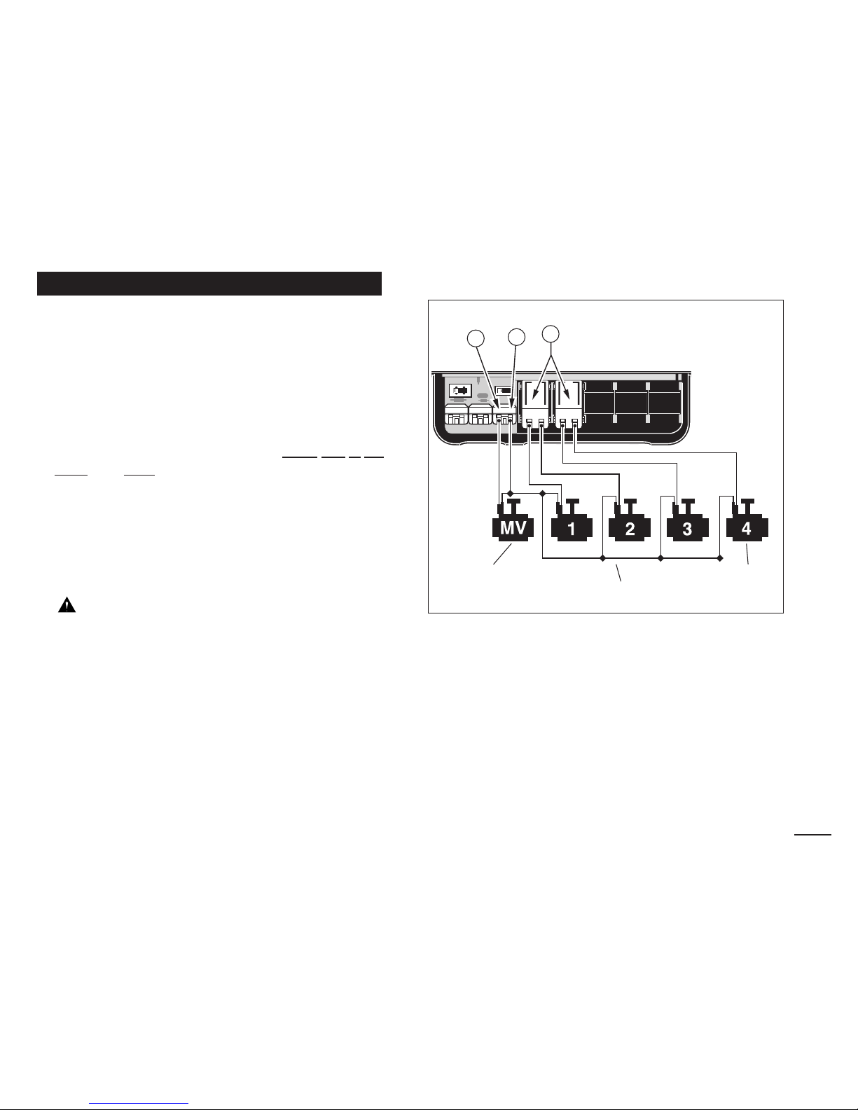
5. Referring to the Timer Components on page 5 and the
diagram above, secure the valve common wire to the
terminal labeled COM (8). Connect the individual zone
valve wires to the appropriate zone module terminals
(11). Connect the master valve wire (if applicable) to
the terminal labeled PUMP/MV (9).
Note: Connecting a master valve or pump start relay
is optional and may not be required in your sprinkler
system.
Connecting the Valves
7
SENSOR
24 VAC PUMP/MV COM
MANUAL
START
ON
NEXT
OFF
Valve Common Wire
Zone Valves
Master Valve
11
8
9
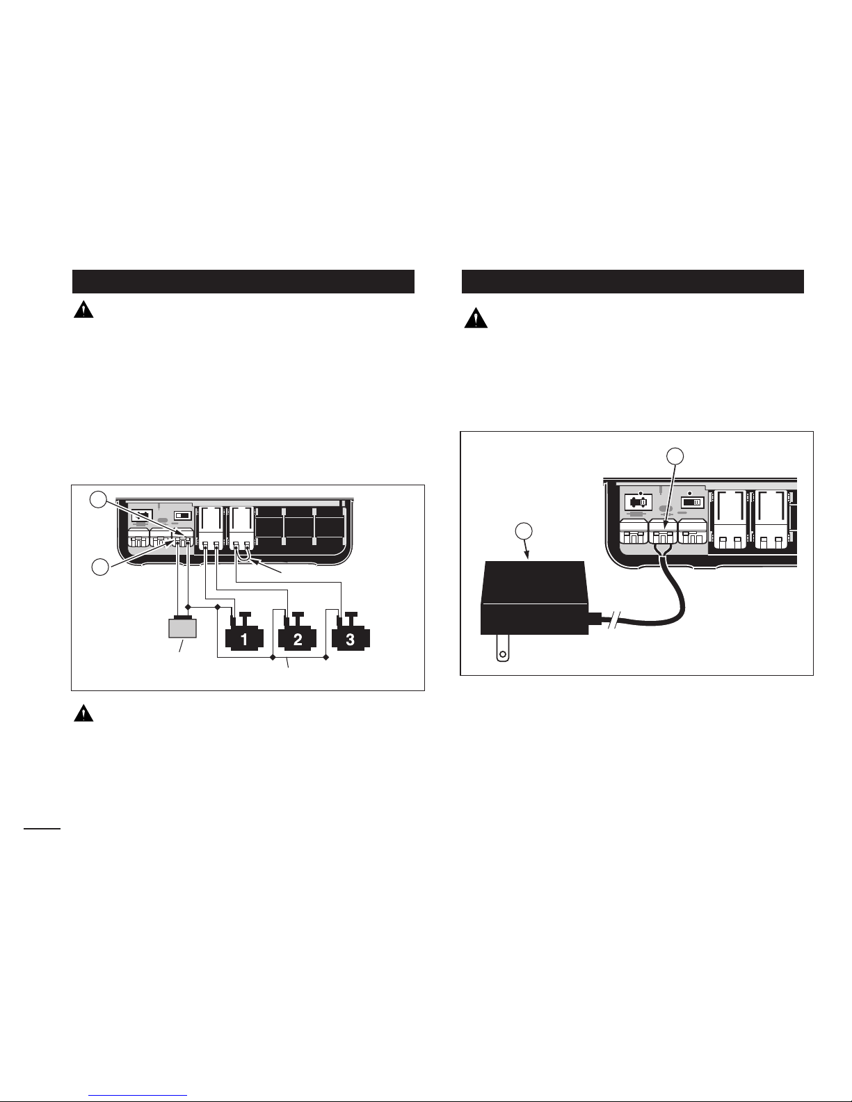
CAUTION: To prevent timer damage, ensure the
24 V ac pump relay current draw does not exceed
0.30 Amps. Do not connect the timer directly to the
pump starter.
1. Route a wire pair from the pump relay into the timer
housing.
2. Connect one wire to the terminal labeled COM (8).
Connect the remaining wire to the terminal labeled
PUMP/MV (9) as shown below.
CAUTION: To prevent pump damage due to
“dead-heading,” connect a jumper wire from any
unused zone terminal to a zone terminal with a valve
connected.
Note: Refer to “Pump Control” section on page 29 for
important pump control information.
CAUTION: Do not plug the transformer into an
electrical outlet until all of the wiring procedures
have been completed.
1. Route the cord from the transformer (13) through the
small opening provided in the base of the housing as
shown below.
2. Connect one transformer cable wire to each terminal
labeled 24 VAC (10). The wires can be connected to
either terminal.
Note: The display will begin flashing 12:00
AM. Press any
button to stop the display from flashing.
Connecting the Plug-In TransformerConnecting a Pump Start Relay
8
SENSOR
24 VAC
ST
10
13
SENSOR
24 VAC PUMP/MV COM
24 V a.c.
Pump Relay
Valve Common Wire
Jumper Wire
12
13
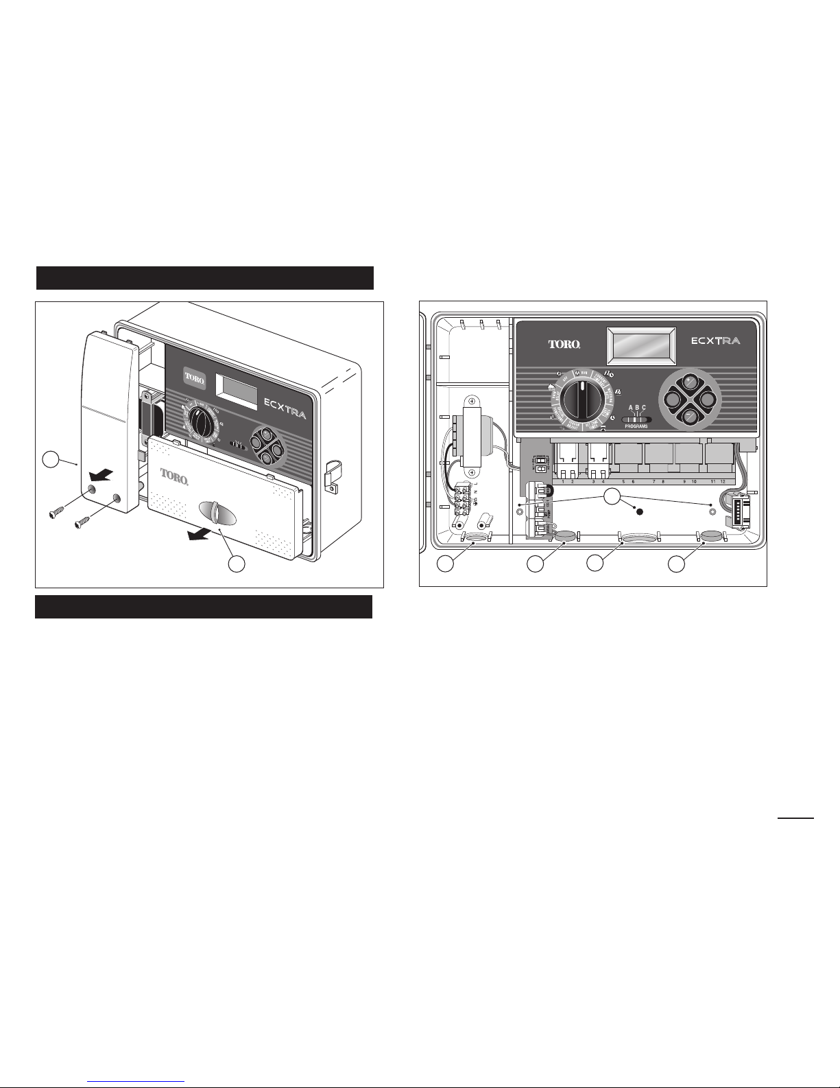
1. Remove the lower housing cover (A) by pulling
outward on the handle.
2. Remove two phillips screws from the transformer
access cover (B). Pull the cover outward from the
bottom to remove.
3. Three lower mounting holes (C) are provided. The
center hole is open and the outer holes are plugged. If
you intend to use the outer holes for installation, carefully drill through the plugs with a 3/16" drill bit.
Four wiring access holes are provided in the cabinet base
as follows:
(D) - 1/2" for power and equipment ground wires.
(E) - 1/2" (plugged) for optional Toro Rain Sensor wires.
(F) - 3/4" for sprinkler valve wires.
(G) - 1/2" (plugged) for optional Toro remote control cable.
4. If planning to install the optional Toro components,
remove the plugs as necessary.
Outdoor Model Installation
Preparing the Cabinet for Installation
9
MANUAL
START
ON
NEXT
OFF
MANUAL
START
ON
NEXT
OFF
PROGRAMS
B
C
A
RRR
R
B
CA
MANUAL
START
ON
NEXT
OFF
A
B
C
F
E
D
G
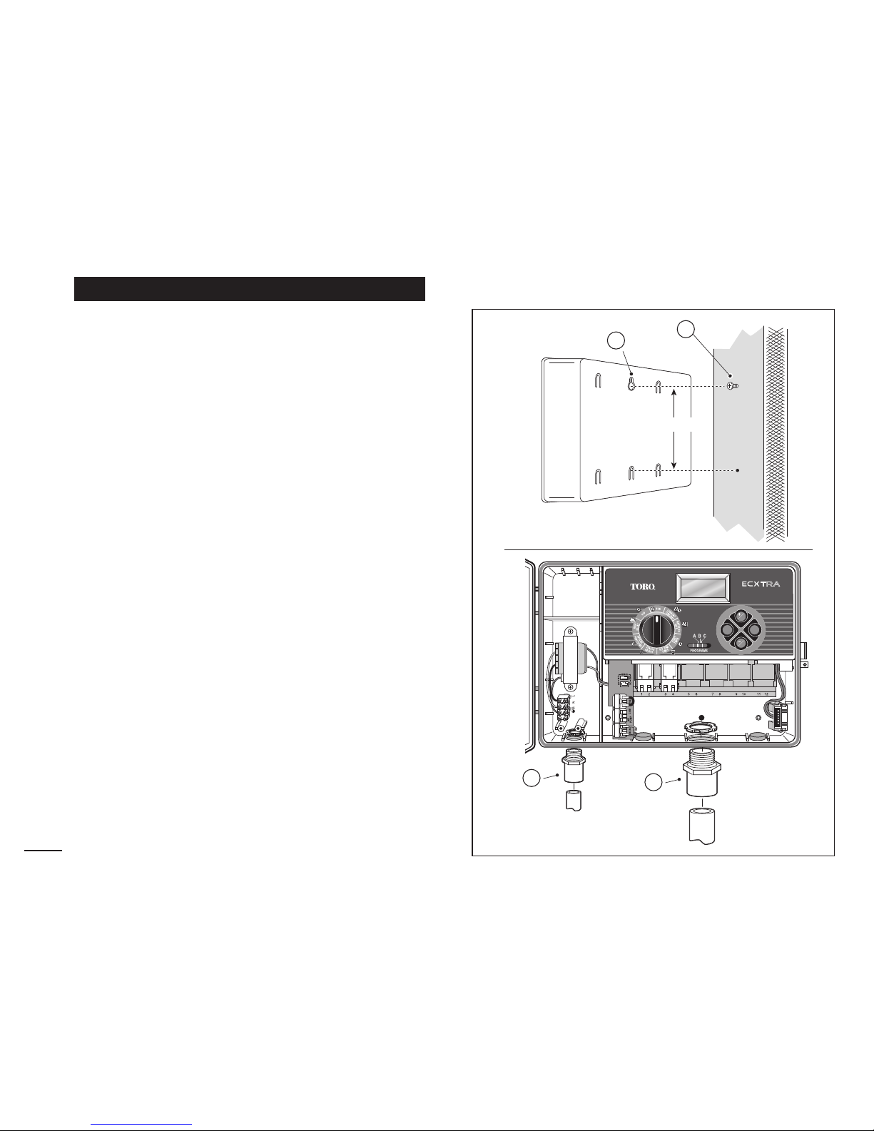
1. For safe, reliable operation, select an installation site
which will provide the following conditions:
• Protection from irrigation spray, exposure to direct
sun during the hottest hours, wind and snow.
• Access to a grounded power source which is not
controlled by a light switch or utilized by a high
current load appliance, such as a refrigerator or air
conditioner.
• Access to the sprinkler control valve wiring and
optional accessory wiring.
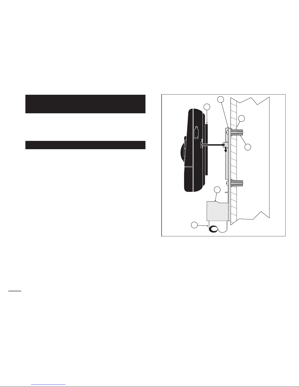
2. Drive a wood screw (provided) into the wall at eye
level (A). Leave the screw extended approximately
1/4" from the wall.
Note: If you are installing the timer on drywall or
masonry, install screw anchors to prevent screws
from loosening. Use the dimension shown to predrill
holes for screw anchors.
3. Hang the cabinet on the screw using the keyhole
slot (B) on the back panel. Make sure the cabinet
slides down securely on the screw.
4. Install the lower mounting screw(s) and tighten
securely.
Note: Conduit and adapters are not provided. Install
conduit as required by local electrical codes.
5. Install 1/2" conduit (C) for power/equipment ground
wires and 3/4" conduit (D) for valve wires.
Note: After installation, store the User’s Guide and
Quick Reference Guide on the hook located on the
inside of the door.
Installing the Cabinet
10
MANUAL
START
ON
NEXT
OFF
6"
B
A
D
C
11
1. Route the valve wires or wire cable from the valves,
into the timer cabinet.
Note: The snap-in wire connectors accept 14 to 18
gauge wire. Using 18-gauge, multi-strand, direct-burial
irrigation cable is recommended. Choose a cable that
has at least one more wire conductor than the number
of valves to be connected.
2. Attach the white color-coded wire to either
one of the
wires from each valve solenoid. This is called the
valve common wire.
3. Attach an individual color-coded wire to the remaining
wire from each valve solenoid. Make a note of the
wire color used for each valve and the watering zone
it controls. You will need to have this information
when connecting the valve wires to the timer.
CAUTION: Use Toro Waterproof Wire Connectors
(Model # 53687) or grease caps on all exposed wire
splice connections to prevent corrosion, connection
failure and possible short circuit.
4. Route the wire cable into the timer through the large
opening in the base of the housing or through PVC
conduit (if it is installed). Strip insulation back 1/2"
from all cable wires.
Note: The zone module has snap-in wire terminals.
To attach wires, simply raise the lever, insert the
stripped wire, and press the lever down to secure.
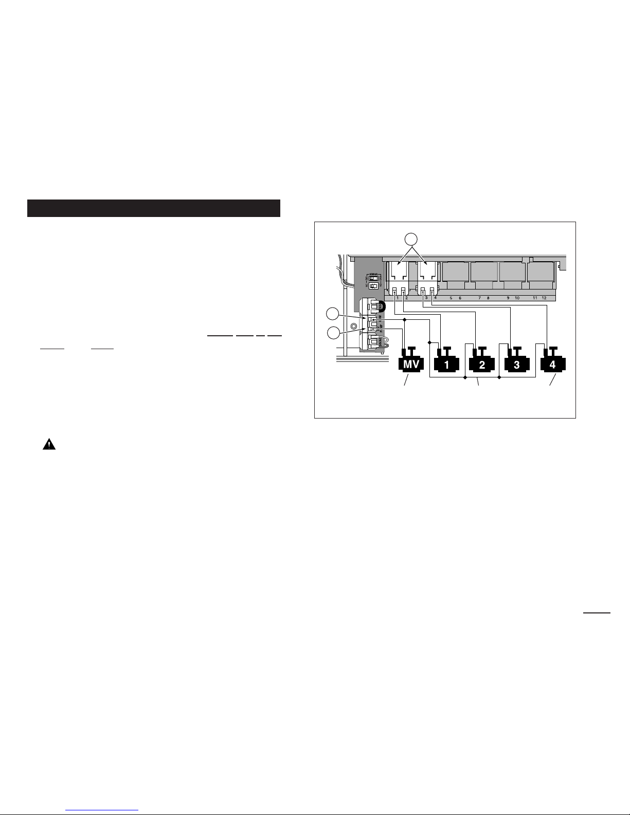
5. Referring to the Timer Components on page 5 and the
diagram above, secure the valve common wire to the
terminal labeled COM (8). Connect the individual zone
valve wires to the appropriate zone module terminals
(11). Connect the master valve wire (if applicable) to
the terminal labeled PUMP/MV (9).
Note: Connecting a master valve or pump start relay
is optional and may not be required in your sprinkler
system.
Connecting the Valves
Valve Common
Wire
Zone
Valves
Master
Valve
11
8
9
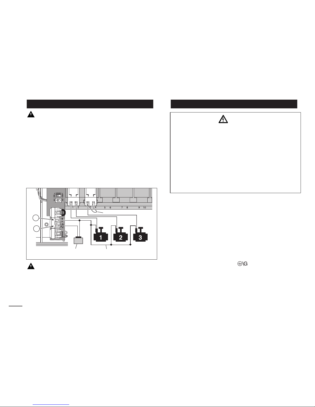
CAUTION: To prevent timer damage, ensure the
relay current draw does not exceed 0.30 Amps. Do
not connect the timer directly to the pump starter.
1. For pump relay wires, install a 1/2" conduit adapter
and conduit.
2. Connect a wire pair to the pump relay terminals and
route the cable through the conduit and into the timer
housing.
3. Connect one wire to the terminal labeled COM (12).
Connect the remaining wire to the terminal labeled
PUMP/MV (13) as shown below.
CAUTION: To prevent pump damage due to
“dead-heading,” connect a jumper wire from any
unused zone terminal to a zone terminal with a valve
connected.
Note: Refer to “Pump Control” section on page 29 for
important pump circuit control information.
1. Route the power and equipment ground wires from the
power source, through the conduit and into the timer
transformer compartment.
Note: The timer terminal block accepts wire size up to
14 gauge.
2. Remove 3/8" insulation from the wire ends.
3. Using a small flat blade screwdriver, secure the wires
as shown to the terminal block as follows:
Line or Line 1 (L1) to L, Neutral or Line 2 (L2) to N
and Equipment Ground to .
4. Install and secure the transformer compartment
cover.
5. Apply power to the timer.
Note: The display will begin flashing 12:00
AM. Press any
button to stop the display from flashing.
Connecting the Power SourceConnecting a Pump Start Relay
12
24 V a.c.
Pump Relay
Valve Common Wire
Jumper Wire
WARNING:
AC power wiring must be installed and connected
by qualified personnel only. All electrical components and installation procedures must comply
with all applicable local and national electrical
codes. Some codes may require a means of disconnection from the AC power source installed in the
fixed wiring and having a contact separation of at
least 0.120" in the line and neutral poles.
Make sure the power source is OFF prior to connecting the timer.
12
13
 Loading...