

Page 1

ProLine Trimmers
Model No. 53002 — 895001 & Up
Model No. 53003 — 895001 & Up
Model No. 53010 — 895001 & Up
Model No. 53011 — 895001 & Up
16” & 18” Gas
Modèle No. 51903 — 790000001 et suivants
Modèle No. 51904 — 790000001 et suivants
Modèle No. 51906 — 790000001 et suivants
Modèle No. 51907 — 790000001 et suivants
FORM NO. 3322-364
16” & 18” Gas
Modelos N. 51903 — 790000001 y siguientes
Modelos N. 51904 — 790000001 y siguientes
Modelos N. 51906 — 790000001 y siguientes
Modelos N. 51907 — 790000001 y siguientes
Operator’s Manual
Manuel de l’Utilisateur
Manual del Usuario
Page 2

Contents
Introduction 2. . . . . . . . . . . . . . . . . . . . . . . . . . . . . . . . .
Safety 3. . . . . . . . . . . . . . . . . . . . . . . . . . . . . . . . . . . . . .
Operator Safety 3. . . . . . . . . . . . . . . . . . . . . . . . . . .
String Trimmer Safety 3. . . . . . . . . . . . . . . . . . . . . .
Fuel Safety 3. . . . . . . . . . . . . . . . . . . . . . . . . . . . . . .
Power String Trimmer Operating Safety 4. . . . . . . .
Safety and Instruction Decals 5. . . . . . . . . . . . . . . . .
Assembly 6. . . . . . . . . . . . . . . . . . . . . . . . . . . . . . . . . . .
Installing Trimmer Head Shield 6. . . . . . . . . . . . . . .
Installing Trimmer Head 7. . . . . . . . . . . . . . . . . . . .
Before Operation 7. . . . . . . . . . . . . . . . . . . . . . . . . . . . .
Oil and Fuel 7. . . . . . . . . . . . . . . . . . . . . . . . . . . . . .
Mixing Gasoline And Oil 8. . . . . . . . . . . . . . . . . . . .
Starting And Stopping 9. . . . . . . . . . . . . . . . . . . . . .
Hot Restart 1 1. . . . . . . . . . . . . . . . . . . . . . . . . . . . . . .
Operation 11. . . . . . . . . . . . . . . . . . . . . . . . . . . . . . . . . . .
Operating Position 11. . . . . . . . . . . . . . . . . . . . . . . . .
Cutting with Nylon Trimmer Line 12. . . . . . . . . . . . .
Rewinding the Trimmer Spool 13. . . . . . . . . . . . . . . .
Page
Page
Maintenance 15. . . . . . . . . . . . . . . . . . . . . . . . . . . . . . . . .
Air Filter 15. . . . . . . . . . . . . . . . . . . . . . . . . . . . . . . . .
Fuel Filter 16. . . . . . . . . . . . . . . . . . . . . . . . . . . . . . . .
Idle Speed Adjustment 16. . . . . . . . . . . . . . . . . . . . . .
Spark Plug 17. . . . . . . . . . . . . . . . . . . . . . . . . . . . . . .
Cylinder Cooling Fins 19. . . . . . . . . . . . . . . . . . . . . .
Spark Arrester 19. . . . . . . . . . . . . . . . . . . . . . . . . . . .
Gearcase Maintenance 21. . . . . . . . . . . . . . . . . . . . . .
General Cleaning and Tightening 21. . . . . . . . . . . . .
Storage 21. . . . . . . . . . . . . . . . . . . . . . . . . . . . . . . . . . . . .
Accessories 22. . . . . . . . . . . . . . . . . . . . . . . . . . . . . . . . .
Troubleshooting 22. . . . . . . . . . . . . . . . . . . . . . . . . . . . . .
Specifications 23. . . . . . . . . . . . . . . . . . . . . . . . . . . . . . . .
53010/Commercial 23. . . . . . . . . . . . . . . . . . . . . . . . .
53011/Commercial 23. . . . . . . . . . . . . . . . . . . . . . . . .
53002/Industrial 23. . . . . . . . . . . . . . . . . . . . . . . . . . .
53003/Industrial 23. . . . . . . . . . . . . . . . . . . . . . . . . . .
Federal and California Emission Control
Warranty Statement 24. . . . . . . . . . . . . . . . . . . . . . . . . .
Warranty 27. . . . . . . . . . . . . . . . . . . . . . . . . . . . . . . . . . . .
WARNING:
The engine exhaust from this product
contains chemicals known to the State of
California to cause cancer, birth defects,
or other reproductive harm.
1
Page 3
Introduction
Thank you for purchasing a T oro product.
All of us at T oro want you to be completely satisfied with
your new product, so feel free to contact your local
Authorized Service Dealer for help with service, genuine
T oro parts, or other information you may require.
Whenever you contact your Authorized Service Dealer or
the factory, always know the model and serial numbers of
your product. These numbers will help the Service Dealer
or Service Representative provide exact information about
your specific product. You will find the model and serial
number decal located in a unique place on the product
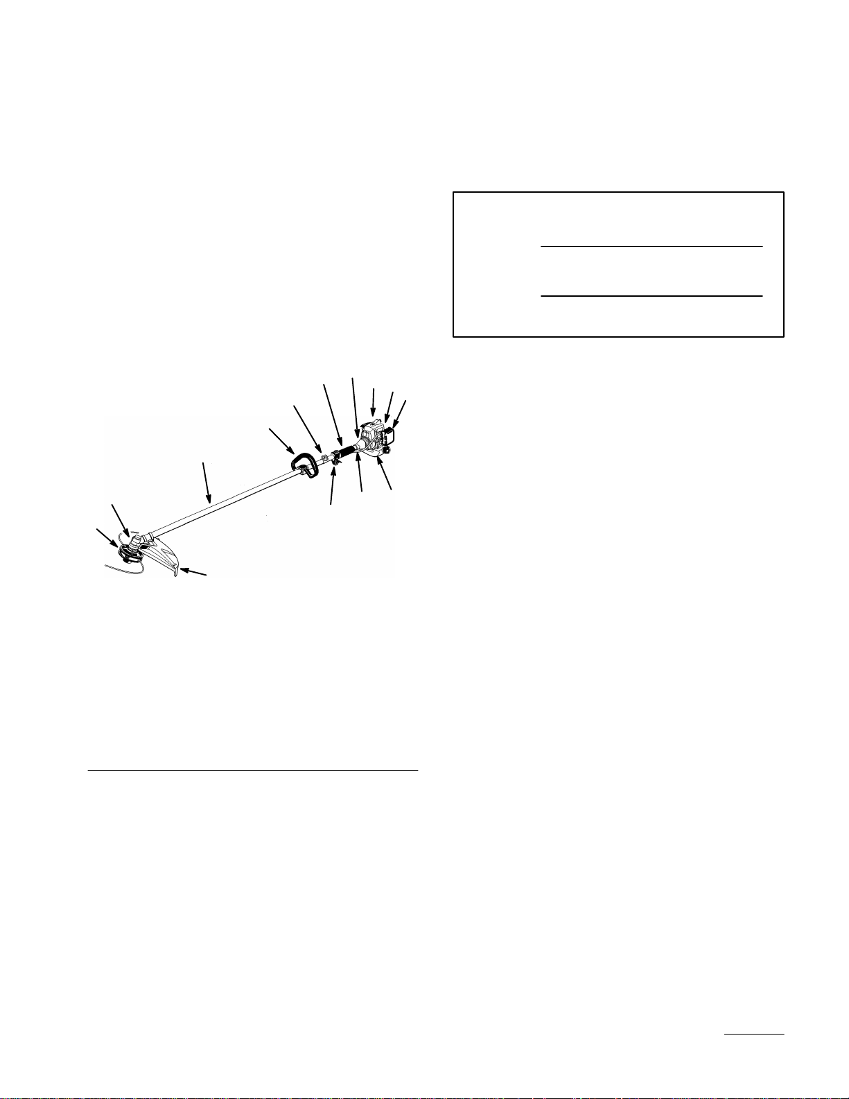
(Fig. 1).
Figure 1
1. Trimmer Head
2. Gearcase
3. Shaft Assembly
4. Loop Handle
5. Attachment Ring for
Shoulder Harness
6. Shaft Grip
7. Clutch Drum Housing
8. Engine
9. Model and Serial Number
Decal (on rear of engine
stand)
10. Air Filter
11. Trimmer Head Shield
12. Throttle Trigger and Stop
Switch
13. Throttle Cable and Stop
Switch Wire
14. Fuel Tank
For your convenience, write the product model and serial
numbers in the space below.
Model No.
Serial No.
Read this manual carefully to learn how to operate and
maintain your product correctly. Reading this manual will
help you and others avoid personal injury and damage to
the product. Although T oro designs, produces and markets
safe, state-of-the-art products, you are responsible for
using the product properly and safely. You are also
responsible for training persons who you allow to use the
product about safe operation.
The Toro warning system in this manual identifies
potential hazards and has special safety messages that help
you and others avoid personal injury, even death.
DANGER, WARNING and CAUTION are signal words
used to identify the level of hazard. However, regardless
of the hazard, be extremely careful.
DANGER signals an extreme hazard that will cause
serious injury or death if the recommended precautions
are not followed.
WARNING signals a hazard that may cause serious injury
or death if the recommended precautions are not followed.
CAUTION signals a hazard that may cause minor or
moderate injury if the recommended precautions are not
followed. T wo other words are also used to highlight
information. “Important” calls attention to special
mechanical information and “Note” emphasizes general
information worthy of special attention.
2
Page 4

Safety
Operator Safety
1. Read and understand this Operator’s Manual before
using this product. Be thoroughly familiar with the
proper use of this product.
2. Always wear eye protection that complies with ANSI
(American National Standards Institute) Z87–1.
3. Always wear hearing protection.
4. Always wear heavy, long pants, boots and gloves. Do
not wear loose clothing, jewelry, short pants, sandals,
or go barefoot. Secure hair so it is above shoulder
length.
5. Never operate this String Trimmer when you are tired,
ill, or under the influence of alcohol, drugs or
medication.
2. Inspect the String Trimmer before each use. Replace
damaged parts. Check for fuel leaks. Make sure all
fasteners are in place and tightened securely. Follow
the maintenance instructions beginning on page 15.
3. Make sure the trimmer head does not rotate at engine
idle speed. Refer to Idle Speed Adjustment, page 16.
4. Inspect the String Trimmer cutting head and replace
any parts that are cracked, chipped or damaged before
using the Trimmer.
5. Install the required shield before using the Trimmer.
6. Use only flexible, non–metallic, monofilament cutting
line of the correct diameter. Never use wire, rope,
string, etc.
7. Never use a cutting head or replacement parts that are
not approved by T oro.
8. Maintain the String Trimmer according to the
recommended maintenance intervals and procedures in
the Maintenance section on page 15.
9. Shut off the engine and wait until the trimmer head has
completely stopped moving before checking,
performing maintenance on or working on the String
Trimmer.
10.If running problems or excessive vibration occur, stop
immediately and inspect the unit for the cause. If the
cause cannot be determined or is beyond your ability
to correct, return the String Trimmer to your servicing
dealer for repair.
6. Never start or run the engine inside a closed room or
building. Breathing exhaust fumes can cause death.
7. Keep handles clean of oil, fuel and dirt.
String Trimmer Safety
1. Make sure the Trimmer is assembled correctly and that
the trimmer head is correctly installed and securely
fastened as instructed in the Assembly section.
3
Fuel Safety
1. Gasoline is highly flammable and must be handled and
stored carefully . Use a container approved for fuel for
storing gasoline and/or fuel/oil mixture.
2. Mix and pour fuel outdoors and where there are no
sparks or flames.
3. Do not smoke near fuel or String Trimmer, or while
using the String Trimmer.
4. Do not overfill the fuel tank. Stop filling 1/4–1/2 inch
(6mm–13mm) from the top of the tank.
5. Wipe up any spilled fuel before starting the engine.
6. Move the Trimmer at least 10 feet (3 m) away from
the fueling location before starting the engine (Fig. 2).
Page 5

m-2966
Figure 2
1. 10 feet (3m) Minimum
7. Do not remove the Trimmer fuel tank cap while the
engine is running, or right after stopping the engine.
8. Allow the engine to cool before refueling.
9. Drain the tank and run the engine dry before storing
the unit.
10.Store fuel and String Trimmer away from open flame,
sparks and excessive heat. Make sure fuel vapors
cannot reach sparks or open flames from water heaters,
furnaces, electric motors, etc.
m-2967
Figure 3
1. 50 ft. (15 m) Minimum
4. If you are approached while operating the Trimmer,
stop the engine and trimmer head rotation.
5. Never allow children to operate the Trimmer.
6. Use the Trimmer only in daylight or good artificial
light.
7. Never operate the Trimmer without proper guards or
other protective safety devices in place.
8. Always keep the Trimmer on the right side of your
body (Fig. 4).
Power String Trimmer
Operating Safety
1. THIS STRING TRIMMER CAN CAUSE SERIOUS
INJURIES. Read the instructions carefully. Be familiar
with all controls and the proper use of the String
Trimmer.
2. Inspect your work area before you begin. Remove
objects such as broken glass, nails, wire and rocks
which can become dangerous projectiles if thrown by
the Trimmer. Remove string, rope or similar materials
which can become entangled in the trimmer head.
3. This Trimmer will throw objects and cut. Keep
children, bystanders and animals outside a 50 ft. (15
m) radius from the operator and Trimmer (Fig. 3).
Beyond the 50 ft. (15 m) there still may be a risk of
injury to bystanders from thrown objects. It is
recommended that bystanders wear eye protection. A
thrown object can ricochet.
m-2968
Figure 4
9. Do not raise the trimmer head above waist level.
10.Keep all parts of your body away from the rotating
trimmer head and hot surfaces such as the muffler.
11. Keep firm footing and balance. Do not overreach.
12.Use the right tool for the job. Do not use the Trimmer
for any job that is not recommended by T oro.
4
Page 6

Safety and Instruction Decals
Safety decals and instructions are easily visible to the operator and are located near any
area of potential danger. Replace any decal that is damaged or lost.
(Part No. M221501)
(Part No. M221502)
ON SHAFT
ON SHAFT
ON ENGINE
(Part No. M266291)
5
Page 7
Assembly
Installing Trimmer Head Shield
POTENTIAL HAZARD
• The cutoff blade is sharp.
WHAT CAN HAPPEN
• Contact with cutoff blade could cause serious
cuts or personal injury.
HOW TO AVOID THE HAZARD
• Keep hands, feet and clothing away from cutoff
blade.
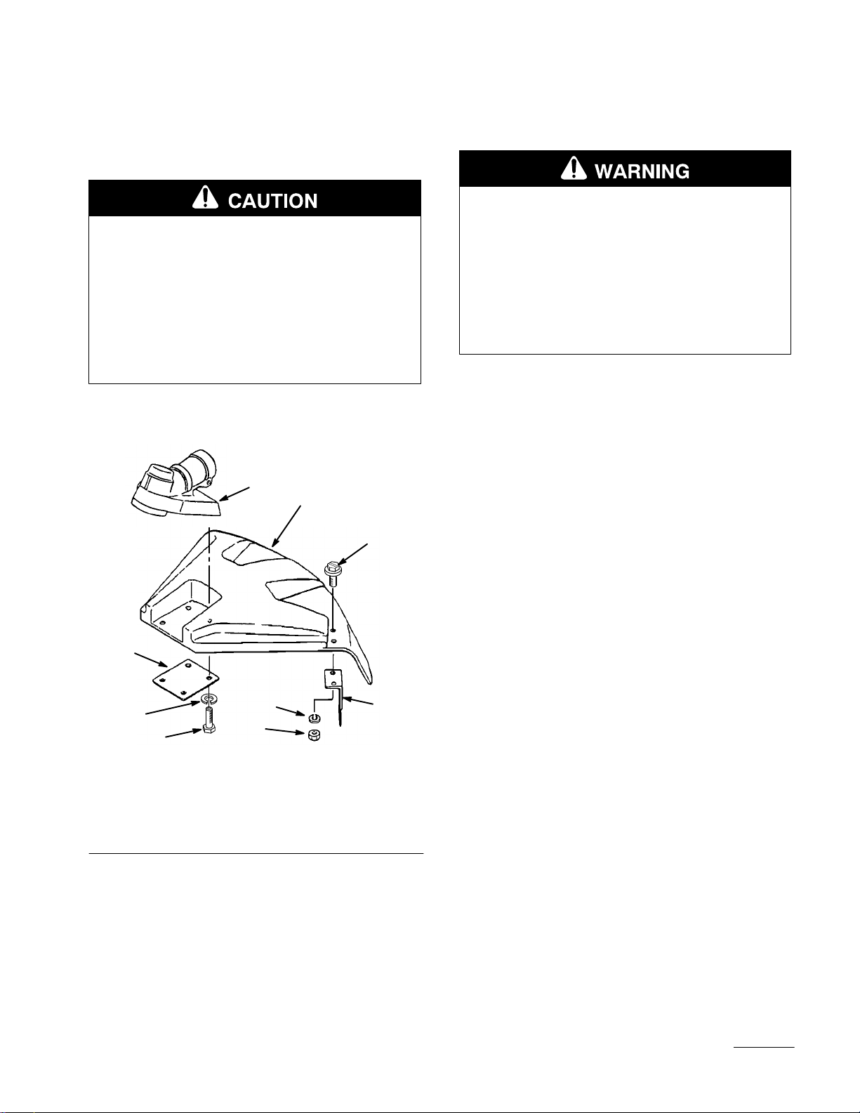
1. Fasten the string cutoff blade to the trimmer head
shield with two M5 x 25 screws, lock washers and hex
nuts as shown (Fig 5).
POTENTIAL HAZARD
• Foreign objects can be thrown by Trimmer.
WHAT CAN HAPPEN
• Contact with thrown objects can cause personal
injury.
HOW TO AVOID THE HAZARD
• Never operate the Trimmer without the
trimmer head shield in place.
2. Attach the trimmer head shield to the gearcase with
the four M5 x 12 screws and lock washers as shown
(Fig 5).
1. Gearcase
2. Trimmer Head Shield
3. M5 x 25 Screw (2)
4. Plate
Figure 5
m-2975
5. Lock Washer
6. M5 x 12 Screw (4)
7. Hex Nut
8. String Cutoff Blade
6
Page 8
Installing Trimmer Head
IMPORTANT: Make sure the trimmer head is for
LEFT-HAND ROTATION (counterclockwise) as
viewed from the operator’s position, and that the
trimmer head adapter is a male, M8 x 1.25 left-hand
thread.
Before Operation
Oil and Fuel
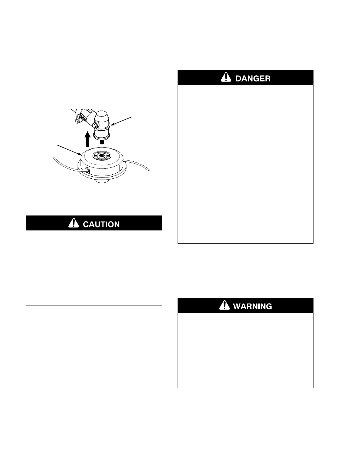
1. Thread the trimmer head into the gearcase, tighten
trimmer head firmly by hand (Fig. 6).
1
2
Figure 6
1. Gearcase 2. Trimmer Head
POTENTIAL HAZARD
• If the trimmer head is not adequately tightened,
it can come loose from the Trimmer during use.
WHAT CAN HAPPEN
• This may cause damage to property or personal
injury.
HOW TO AVOID THE HAZARD
• Make sure the trimmer head is securely
fastened to the splined shaft in the gearcase.
POTENTIAL HAZARD
• In certain conditions gasoline is extremely
flammable and highly explosive.
WHAT CAN HAPPEN
• A fire or explosion from gasoline can burn you,
others, and cause property damage.
HOW TO AVOID THE HAZARD
• Use a funnel and fill the fuel tank outdoors, in
an open area, when the engine is cold. Wipe up
any gasoline that spills.
• Do not fill the fuel tank completely full. Add
gasoline to the fuel tank until the level is 1/4” to
1/2” (6 mm to 13 mm) below the bottom of the
filler neck. This empty space in the tank allows
gasoline to expand.
• Never smoke when handling gasoline, and stay
away from an open flame or where gasoline
fumes may be ignited by a spark.
• Store gasoline in an approved container and
keep it out of the reach of children.
• Never buy more than a 30-day supply of
gasoline.
1. Do not smoke near fuel.
2. Mix and pour fuel outdoors and where there are no
sparks or flames.
3. Always shut off the engine before refueling. Never
remove the String Trimmer fuel tank cap while the
engine is running or right after just stopping the
engine.
POTENTIAL HAZARD
• Gasoline contains gasses that can build up
pressure inside a gas tank.
WHAT CAN HAPPEN
• Fuel can be sprayed on you when removing gas
cap.
HOW TO AVOID THE HAZARD
• Remove fuel cap slowly to avoid injury from
fuel spray.
7
Page 9

4. Always open the fuel tank cap slowly to release any
possible overpressure inside the tank.
5. Do not overfill the fuel tank. Stop filling 1/4–1/2 inch
(6mm–13mm) from the top of the tank.
6. Tighten the tank fuel cap carefully but firmly after
refilling.
7. Wipe up any spilled fuel before starting the engine.
8. Move the String Trimmer at least 10 feet (3 m) away
from the fueling location and fuel storage container
before starting the engine (Fig. 2).
Recommended Oil Type
Only use a two-cycle engine oil formulated for use in
high-performance, air-cooled two-cycle engines. Toro
brand 2-cycle oil is formulated for use in
high-performance, air-cooled two-cycle engines.
IMPORTANT: Do not use National Marine
Manufacturer’s Association (NMMA) or BIA certified
oils. This type of 2–cycle engine oil does not have the
proper additives for air-cooled, 2–cycle engines and
can cause engine damage.
Do not use automotive motor oil. This type of
oil does not have the proper additives for
air-cooled, 2–cycle engines and can cause
engine damage.
DO NOT USE FUEL ADDITIVES OTHER
THAN THOSE MANUFACTURED FOR
FUEL STABILIZATION DURING
STORAGE SUCH AS TORO’S
STABILIZER/CONDITIONER OR A
SIMILAR PRODUCT. TORO’S
STABILIZER/CONDITIONER IS A
PETROLEUM DISTILLA TE BASED
CONDITIONER/STABILIZER.
TORO DOES NOT RECOMMEND
STABILIZERS WITH AN ALCOHOL BASE
SUCH AS ETHANOL, METHANOL OR
ISOPROPYL. ADDITIVES SHOULD NOT
BE USED TO TRY TO ENHANCE THE
POWER OR PERFORMANCE OF
MACHINE.
Mixing Gasoline And Oil
IMPORTANT: The engine used on this String Trimmer
is of a 2–cycle design. The internal moving parts of the
engine, i.e., crankshaft bearings, piston pin bearings
and piston to cylinder wall contact surfaces, require oil
mixed with the gasoline for lubrication.
Failure to add oil to the gasoline or failure to
mix oil with the gasoline at the appropriate
ratio will cause major engine damage which
will void your warranty.
Recommended Fuel Type
Use clean, fresh lead-free gasoline, including oxygenated
or reformulated gasoline, with an octane rating of 85 or
higher. To ensure freshness, purchase only the quantity of
gasoline that can be used in 30 days. Use of lead-free
gasoline results in fewer combustion chamber deposits
and longer spark plug life. Use of premium grade fuel is
not necessary or recommended.
Use Of Fuel Additives
IMPORTANT: NEVER USE METHANOL,
GASOLINE CONTAINING METHANOL,
GASOHOL CONTAINING MORE THAN
10% ETHANOL, PREMIUM GASOLINE,
OR WHITE GAS BECAUSE ENGINE
FUEL SYSTEM DAMAGE COULD
RESULT.
For your fuel premix, only use a quality oil
designed for 2–cycle air cooled engines. Toro
50:1 2–Cycle Oil is formulated to meet the
requirements of high-performance, air-cooled
two-cycle engines.
Fuel Mixture
The fuel:oil ratio is 50 parts gasoline to 1 part oil or 50:1.
Note: Never use a mixing ratio less than 50:1
regardless of the oil package mixing instructions.
Ratios less the 50:1, (for example, 60:1, 80:1, 100:1),
reduce the amount of lubrication to the internal
moving parts of the engine and can cause damage.
8
Page 10

Fuel Mixture Chart
Starting And Stopping
Before Starting The Engine
Gasoline 50:1 2-cycle oil
1 gallon 2.6 oz.
2 gallons 5.2 oz.
5 gallons 12.8 oz.
Mixing Instructions
IMPORTANT: Never mix gasoline and oil directly in
the String Trimmer fuel tank.
1. Always mix fuel and oil in a clean container approved
for gasoline.
2. Mark the container to identify it as fuel mix for the
String Trimmer.
3. Use regular unleaded gasoline and fill the container
with half the required amount of gasoline.
4. Pour the correct amount of oil into the container then
add the remaining amount of gasoline.
1. Fill the fuel tank as instructed in the Before Operation
section of this manual.
2. Rest the String Trimmer on the ground.
3. Make sure the trimmer head is clear of any broken
glass, nails, wire, rocks or other debris.
4. Keep all bystanders, children and animals away from
the working area.
Cold Starting Procedure
The carburetors on T oro engines contain a choke system.
T o start a “cold” engine properly, perform the following
procedure:
1. Pump the primer bulb at the bottom of the carburetor
until fuel can be seen flowing through the fuel return
line to the fuel tank (Figs. 7 and 8). (Flowing fuel
should be almost clear, not foamy or full of bubbles.)
5. Close the container tightly and shake it momentarily to
evenly mix the oil and the gasoline before filling the
fuel tank on the String Trimmer.
6. When refilling the String Trimmer fuel tank, clean
around the fuel tank cap to prevent dirt and debris
from entering the tank during cap removal.
7. Always shake the premix fuel container momentarily
before filling the fuel tank
8. Always use a spout or funnel when fueling to reduce
fuel spillage.
9. Fill the tank only to within 1/4–1/2 inch (6mm–13mm)
from the top of the tank. Avoid filling to the top of the
tank filler neck.
1
Model 53002 & 53003
Figure 7
1. Primer Bulb 2. Fuel Return Line
1
2
m-2978
9
Page 11

1
1
2
Model 53010 & 53011
m-3040
Figure 8
1. Primer Bulb 2. Fuel Return Line
2. Move the choke lever to the closed ( ) position and
move the stop switch to the “ON” position (Figs. 9).
1
2
3
4
Figure 10
1. Stop Switch
2. Fast-idle Lock
3. Throttle Trigger (in
fast-idle start position)
4. Throttle Trigger (in idle
position)
4. After the engine starts, move the choke lever to the
open (
) position, then squeeze and release the
throttle trigger to allow it to return to the idle position
(Figs. 10).
If the engine stops running before you move the choke
lever to the open (
) position:
A. Go ahead and open the choke (Fig. 9).
B. Make sure the throttle trigger is set to the fast-idle
start position (Fig. 10).
C. Pull the starter handle until the engine starts
(Fig. 9).
m-2939
2
m-2938
Figure 9
1. Starter Handle 2. Choke Lever (typical)
3. Lock the throttle trigger in the fast-idle start position,
then pull the starter handle (Figs. 10).
10
Page 12

Hot Restart
T o start an engine that is already warmed up (hot restart),
or if the ambient temperature exceeds 68F (20C):
1. Pump the primer bulb at the bottom of the carburetor
until fuel can be seen flowing through the fuel return
line to the fuel tank (Figs. 7 and 8).
2. Move the choke lever to the open (
move the stop switch to the “ON” position (Figs. 9 and
10).
3. Leave the throttle trigger in the idle position and pull
the starter handle (Figs. 9 and 10).
4. If the engine fails to start after three to four pulls,
follow the instructions in the Cold Starting Procedure
section above.
If the engine fails to start after you follow the above
procedures, contact an authorized T oro dealer.
) position and
To Stop The Engine:
1. Release the throttle trigger (Fig. 10).
1. Hearing Protection
2. Eye Protection
3. Right Arm Slightly Bent
4. Left Arm Fully Extended,
Hand Holding Loop
Handle
1. The Trimmer should be on the operator’s right side.
m-2968
Figure 11
5. Hand Holding Throttle
Grip, Fingers on Throttle
Trigger
6. Trimmer Head Near and
Parallel to Ground
2. Slide the stop switch to the “STOP”
position (Fig. 10).
Operation
• Read the Safety instructions on page 3
concerning proper use of the String Trimmer.
Operating Position
Before using the Trimmer, check the following (Fig. 11):
2. The operator’s right hand should be holding the shaft
grip, with his or her fingers on the throttle trigger. The
right arm should be slightly bent.
3. The left hand should be holding the loop handle with
the fingers and thumb fully enclosed around the grip.
The left arm should be extended. Reposition the loop
handle up or down the driveshaft if necessary for a
comfortable position.
4. The Trimmer weight should be evenly distributed
between the arms. The trimmer head should be near
and parallel to the ground.
5. Accelerate and hold the engine at cutting speed before
entering the material to be cut.
6. Always release the throttle trigger and allow the
engine to return to idle speed when not cutting.
7. Stop the Trimmer engine when moving between work
sites.
11
Page 13

• Always wear gloves and protective clothing
when operating the String Trimmer.
• If the trimmer head becomes jammed, stop the engine
immediately.
• Make certain all moving parts have stopped and
disconnect the spark plug before inspecting the
equipment for damage.
• Never use a String Trimmer that has chipped, cracked
or broken trimmer head.
Cutting with Nylon Trimmer
Line
Figure 13
m-2980
• The tip of the line does the cutting. The line should
stay extended while cutting (Fig. 12).
m-2979
Figure 12
1. Three inches (7.6 cm) Above Ground
• Do not force the line into the material. Forcing the line
will cause it to slap against the material, increasing
line usage and causing poor cutting results (Fig. 13).
Trimming
Hold the bottom of the trimmer head about 3 in. (7.6 cm)
above the ground and at an angle. Allow only the tip of
the line to make contact (Figs. 14).
m-2981
Figure 14
1. Three inches (7.6 cm) Above Ground
12
Page 14

Scaling
T o remove unwanted vegetation, hold the trimmer head
about 3 in. (7.6 cm) above the ground and at an angle.
Allow the tip of the line to strike the ground cutting the
vegetation off at the surface (Fig. 15).
m-2982
Figure 15
Mowing
Rewinding the Trimmer Spool
POTENTIAL HAZARD
• Use of improper line could cause line to break
and be thrown in operator’s or bystander’s
direction.
WHAT CAN HAPPEN
• Use of improper line could result in serious
personal injury.
HOW TO AVOID THE HAZARD
• Use only good quality, commercial grade, weld
resistant trimmer line with a diameter of .095
inches (2.413 mm).
• Do not use any type of wire or other string-like
substance. Do not use metal-reinforced line.
1. Push in on one side of the head where it says to “push
open” then pull on bottom (Figs. 17).
Keep the line parallel to the ground and use a gentle
side-to-side motion (Fig. 16).
Figure 16
m-2983
1
Figure 17
1. Push here
2. Remove the empty spool from the head (Fig. 18).
13
Page 15

1
1
1
Figure 20
1. Groves
Figure 18
1. Spool
3. Clean the dirt from the inside of the spool parts if
required.
4. Cut two (2) new lines (10’–15’) of equal length.
5. Place ends of line in holes on inside of spool
(Figs. 19).
6. Place the two (2) lines through the slits and wind the
line in even, tight layers onto the spool in the direction
indicated on the spool (Figs. 19).
3
1
2
2
8. Thread the two ends of the line through the eyelets,
place spool into head and pull line to release from
grooves (Figs. 21).
1
1
Figure 21
1. Eyelets
9. Align the eyelet projections andsnap the cover and
head together (Figs. 22).
3
Figure 19
1. Holes
2. Slits
3. Wind direction arrow
7. Snap the two (2) ends in the grooves as indicated,
leaving 3-4 inches of line to be placed through eyelets
(Figs. 20).
14
Page 16

Figure 22
Maintenance
NOTICE:Maintenance, replacement or repair of the
emission control devices and systems may be
performed by any non-road engine repair
establishment or individual. However, to obtain no
charge repairs under the terms and provisions of the
Toro warranty statement, any service or emission
control part repair or replacement must be performed
by an Authorized Toro Service Dealer.
Air Filter
Maintenance Interval
• The air filter should be cleaned daily, or more often
when working in extremely dusty conditions.
• Replace after every 100 hours of operation.
Air Filter Cleaning
Figure 23
1. Air Filter Cover 2. Foam Filter
Model 53002 & 53003
1. Loosen the knob and remove the air filter cover
(Fig. 24).
2. Remove the foam ring and filter screen from the air
filter cover (Fig. 24).
3. Clean the foam ring and filter screen with warm, soapy
water. Let the screen and ring dry completely.
4. Apply a light coat of SAE 30 motor oil to the foam
ring and squeeze out all excess oil.
5. Reassemble the filter screen and foam ring to the air
filter cover (Fig. 24).
m-2930
Model 53010 & 53011
1. Unsnap the air filter cover (Fig. 23).
2. Remove the foam filter (Fig. 23).
3. Clean the filter with warm, soapy water. Let the filter
completely dry.
4. Apply a light coat of SAE 30 motor oil to the foam
filter and squeeze out all excess oil.
5. Reassemble the filter and filter cover (Fig. 23).
15
1. Air Filter Cover
2. FIlter Screen
m-2997
Figure 24
3. Foam Ring
Page 17

IMPORTANT: The air filter screen is designed to fit
into the air filter cover ONE WAY ONLY . Make sure
the cutouts in the screen fit onto the matching plastic
posts in the air filter cover. The fit should be snug
(Fig. 25).
5. While still holding on to the fuel hose, attach the new
fuel filter.
6. Drop the new fuel filter back into the fuel tank.
7. Make sure that the fuel filter is not stuck in a corner of
the tank, and that the fuel hose is not doubled over
(kinked) before refueling.
Figure 25
1. Filter Screen
2. Cutout (typical)
3. Air Filter Cover
4. Plastic Post (typical)
6. Reinstall the air filter cover and tighten the knob
(Fig. 24).
Fuel Filter
m-3010
m-2931
Figure 26
1. Wire
2. Fuel Pick-up Hose
3. Fuel Filter
Idle Speed Adjustment
This String Trimmer is equipped with non-adjustable fuel
mixture carburetor. The engine idle speed is the only
adjustment for the operator.
Maintenance Interval
The fuel filter should be replaced after every 100 hours of
operation.
Fuel Filter Replacement
The fuel filter is attached to the end of the fuel pick-up
hose inside the fuel tank (Fig. 26).
T o replace the fuel filter:
1. Make sure the fuel tank is empty.
2. Remove the fuel cap.
3. Using a wire hook, gently pull the fuel filter out
through the fuel filler opening (Fig. 26).
4. Grasp the fuel hose next to the fuel filter fitting and
remove the filter, but do not release the hose.
POTENTIAL HAZARD
• Engine must be running to make some
carburetor adjustments.
• When engine is running, trimmer head is
rotating and other parts are moving.
WHAT CAN HAPPEN
• Contact with rotating trimmer head or other
moving parts could cause serious personal
injury or death.
HOW TO AVOID THE HAZARD
• Keep hands, feet and clothing away from
trimmer head and other moving parts.
• Keep all bystanders and pets away from unit
while making carburetor adjustments.
The trimmer head may be rotating during idle speed
adjustment. Wear the recommended personal protective
equipment and observe all safety instructions. Keep hands
and body away from the trimmer head.
16
Page 18

When the throttle trigger is released, the engine should
return to an idle speed between 2400 and 2800 RPM, or
just below the clutch engagement speed. The trimmer
head must not rotate and the engine should not stall (stop
running) at engine idle speed (Fig. 27).
m-2974
Figure 28
1. Idle Speed Adjustment Screw
m-2968
Figure 27
1. Throttle Trigger in Idle
Position
2. No Trimmer Head
Rotation
T o adjust the engine idle speed, rotate the idle speed
adjustment screw on the carburetor (Fig. 28).
• Turn the idle speed screw in (clockwise) to increase
the engine idle speed.
• Turn the screw out (counterclockwise) to decrease the
engine idle speed.
Spark Plug
Maintenance Interval
• The spark plug should be removed from the engine
and checked after each 25 hours of operation.
• Replace the spark plug (NGK BPM6Y) after every 100
hours of operation.
Spark Plug Maintenance
Model 53010 & 53011
1. With the engine at ambient (room) temperature,
remove the socket head screw holding the muffler
cover, then remove the muffler cover (Fig. 30).
2. Loosen the cylinder cover screw and lift off the
cylinder cover (Fig. 29).
If idle speed adjustment is necessary, and after
adjustment the trimmer head rotates or the engine
stalls, stop using the String Trimmer immediately!
Contact your local authorized T oro Dealer for assistance
and servicing.
17
m-2934
Figure 29
1. Screw 2. Cylinder Cover
Page 19

3. T wist the high tension lead boot on the spark plug back
and forth a couple of times to loosen the boot, then
pull the boot off of the spark plug.
4. Remove the spark plug.
5. Clean the electrodes with a stiff brush (Fig. 32).
6. Adjust the electrode air gap to .024–.028 in.
(0.6–0.7mm) (Fig. 32).
m-2997
7. Replace the spark plug if it is oil-fouled, damaged, or
if the electrodes are worn down.
8. Do not overtighten the spark plug when installing. The
tightening torque is 95–148 in. lbs. (10.7–16.6 NSm).
9. Reinstall the cylinder and muffler covers
(Figs. 29 and 30).
m-2927
Figure 31
1. Air Filter Cover
2. FIlter Screen
3. Foam Ring
3. T wist the high tension lead boot on the spark plug back
and forth a couple of times to loosen the boot, then
pull the boot off of the spark plug.
4. Remove the spark plug.
5. Clean the electrodes with a stiff brush (Fig. 32).
6. Adjust the electrode air gap to .024–.028 in.
(0.6–0.7mm) (Fig. 32).
7. Replace the spark plug if it is oil-fouled, damaged, or
if the electrodes are worn down.
8. Do not overtighten the spark plug when installing. The
tightening torque is 95–148 in. lbs. (10.7–16.6 NSm).
9. Reinstall the cylinder and air cleaner covers (Fig. 31).
Figure 30
1. Muffler Cover 2. Socket Head Screw
Model 53002 & 53003
1. With the engine at ambient (room) temperature, loosen
the knob and remove the air cleaner cover (Fig. 31).
2. Loosen the knob and lift off the cylinder cover
(Fig. 31).
m-2932
Figure 32
1. .024”–.028” (0.6–0.7 mm)
18
Page 20

Cylinder Cooling Fins
Maintenance Interval
The cylinder cooling fins should be cleaned after every 25
hours of operation, or once a week, whichever comes first.
Air must flow freely around and through the cylinder
cooling fins to prevent engine overheating. Leaves, grass,
dirt and debris buildup on the fins will increase the
operating temperature of the engine, which can reduce
engine performance and shorten engine life.
Cooling Fin Cleaning
Model 53010 & 53011
1. With the engine cool (ambient or room temperature),
remove the socket head screw holding the muffler
cover, then remove the muffler cover (Fig. 30).
2. Loosen the cylinder cover screw and remove the
cylinder cover (Fig. 29).
Figure 33
1. Air Filter Cover
2. FIlter Screen
Spark Arrester
m-3041
3. Foam Ring
3. Clean all dirt and debris from the cooling fins and
from around the cylinder base.
4. Reinstall the cylinder cover and the muffler cover
(Figs 30 and 29).
Model 53002 & 53003
1. With the engine at ambient (room) temperature, loosen
the knob and remove the air cleaner cover (Fig. 33).
2. Loosen the knob and lift off the cylinder cover
(Fig. 33).
3. Clean all dirt and debris from the cooling fins and
from around the cylinder base.
4. Reinstall the cylinder and air cleaner covers (Fig. 33).
POTENTIAL HAZARD
• Muffler surface becomes hot when Trimmer is
in operation and remains hot for some time
after the engine is shut off.
WHAT CAN HAPPEN
• Contact with hot muffler surfaces could cause a
burn.
HOW TO AVOID THE HAZARD
• Make sure the muffler is cool before inspecting
and cleaning the spark arrester.
Maintenance Interval
• The spark arrester should be inspected and cleaned
after every 25 hours of use.
• Replace the screen if it cannot be thoroughly cleaned,
or if it is damaged.
19
Page 21

Spark Arrester Maintenance
Model 53010 & 53011
1. With the engine at ambient (room) temperature,
remove the socket head screw holding the muffler
cover, then remove the muffler cover (Fig. 30).
2. Remove the four socket head screws holding the spark
arrester assembly to the muffler (Fig. 34).
3. Remove and clean the tail, screen, gasket and plate
with a safety solvent and a stiff brush. If any part
cannot be thoroughly cleaned, it must be replaced.
4. Reinstall the plate, gasket, screen and tail onto the
muffler, then reinstall and tighten the four socket head
screws (Fig. 34).
5. Reinstall the spark arrester, gasket and tail onto the
muffler, then reinstall and tighten the two socket head
screws (Fig. 35).
m-3042
Figure 35
1. Socket Head Screw (2)
2. Tail
3. Gasket
4. Spark Arrester
5. Muffler
m-3043
Figure 34
1. Socket Head Screw (4)
2. Tail
3. Screen
4. Gasket
5. Plate
6. Muffler
5. Reinstall the muffler cover (Fig. 30).
Model 53002 & 53003
1. With the engine at ambient (room) temperature, loosen
the knob and remove the air cleaner cover (Fig. 33).
2. Loosen the knob and lift off the cylinder cover
(Fig. 33).
3. Remove the two socket head screws holding the spark
arrester assembly to the muffler (Fig. 35).
4. Remove and clean the tail, gasket and spark arrester
with a safety solvent and a stiff brush. If any part
cannot be thoroughly cleaned, it must be replaced.
6. Reinstall the cylinder and air cleaner covers (Fig. 33).
20
Page 22

Gearcase Maintenance
The gearcase is a sealed unit which has been greased at
the factory. No gearcase maintenance or lubrication is
required or recommended.
General Cleaning and
Tightening
POTENTIAL HAZARD
• When engine is running, cutting head is
rotating and other parts are moving.
WHAT CAN HAPPEN
• Contact with rotating cutting head or other
moving parts could cause serious personal
injury or death.
HOW TO AVOID THE HAZARD
• Always turn off your Trimmer before you clean
or perform any maintenance on it.
5. Remove the spark plug and squirt a very small amount
of oil into the cylinder (Fig. 36).
Figure 36
The T oro String Trimmer will provide maximum
performance for many, many hours if it is maintained
properly. Good maintenance includes regular checking of
all fasteners for correct tightness, and cleaning the entire
machine.
Storage
For long-term storage of the String Trimmer:
1. Empty the fuel tank into a suitable fuel storage
container.
2. Pump the primer bulb on the carburetor until all fuel is
discharged through the clear fuel return hose.
3. Run the engine to remove any fuel that may remain in
the carburetor.
4. Perform all regular maintenance procedures and any
needed repairs.
POTENTIAL HAZARD
• Oil may squirt out of the spark plug opening
when you pull the starter handle.
WHAT CAN HAPPEN
• Oil can cause eye injuries.
HOW TO AVOID THE HAZARD
• Protect your eyes and keep your face away
from the spark plug opening.
6. Pull the starter handle once.
7. Slowly pull the starter handle to bring the piston to the
top of the cylinder (TDC).
8. Reinstall the spark plug.
9. Store the String Trimmer in a dry place away from
excessive heat, sparks or open flame.
21
Page 23

Accessories
The following accessories may be purchased at your local
authorized TORO Service Dealer .
1. Single Strap Harness, Model No. 46–2951 and
Deluxe Strap Harness, Model No. 46–2961—safety
release straps made out of durable nylon webbing
(Fig. 37).
POTENTIAL HAZARD
• Without the Brushcutter blade shield installed
on the String Trimmer, the Brushcutter blade
can throw foreign objects.
• Without the correct blade shield, handles and
strap installed on the String Trimmer, the
Brushcutter can produce side thrust which can
expose the operator and bystanders to blade
contact.
WHAT CAN HAPPEN
• Contact with the Brushcutter blade or thrown
objects can cause severe personal injury .
HOW TO AVOID THE HAZARD
• Never install only a Brushcutter blade onto a
String Trimmer.
• To convert a String Trimmer to a Brushcutter,
you must purchase and install the entire
Brushcutter Accessory Kit.
2. Brushcutter Accessory Kit, Model No.
53050—allows you to convert the String Trimmer to a
Brushcutter; available for Industrial Models (53002
and 53003) only.
1. Red Band
2. Strap
Figure 37
3. Ring
Troubleshooting
Problem Cause Action
Engine Will Not Start
Engine Will Not Idle Idle speed set incorrectly Set idle speed
Engine Lacks Power or Stalls When
Cutting
STOP switch set to off position
Empty fuel tank
Primer bulb wasn’t pushed enough Press primer bulb until fuel flows
Engine flooded Use warm engine starting
Throttle wire has come loose Tighten throttle wire
Dirty air filter Clean or replace air filter
Move switch to on position
Fill fuel tank
through fuel return line
procedure
If further assistance is required, contact your local authorized Toro service dealer.
22
Page 24

Specifications
Note: All models are CARB approved.
53010/Commercial
Engine Displacement 23cc
Shaft Straight (59”/150 cm)
steel with 5 ball
bearings, 5 bushings
Anti Vibration Dual Isolation – grip and
engine mount
Carburetor Walbro – Choke Type
Ignition System Solid State
Fuel Tank Capacity 0.63 qts. (0.6 liter)
Gas to Oil Ratio 50:1
Cutting Head 4” Semiautomatic
Weight 12.6 lbs. (5.7 kg)
Spark Plug NGK BPM6Y
Spark Plug Gap .024–.028 in
(0.6–0.7mm)
53002/Industrial
Engine Displacement 26cc
Shaft Straight (59”/150 cm)
steel with 6 ball
bearings, 5 bushings
Anti Vibration Dual Isolation – grip and
engine mount
Carburetor Walbro – Choke Type
Ignition System Solid State
Fuel Tank Capacity 0.85 qts. (0.8 liter)
Gas to Oil Ratio 50:1
Cutting Head 5” Semiautomatic
Weight 14.8 lbs. (6.7 kg)
Spark Plug NGK BPM6Y
Spark Plug Gap .024–.028 in
(0.6–0.7mm)
53011/Commercial
Engine Displacement 26cc
Shaft Straight (59”/150 cm)
steel with 6 ball
bearings, 5 bushings
Anti Vibration Dual Isolation – grip and
engine mount
Carburetor Walbro – Choke Type
Ignition System Solid State
Fuel Tank Capacity 0.74 qts. (0.7 liter)
Gas to Oil Ratio 50:1
Cutting Head 4” Semiautomatic
Weight 13.3 lbs. (6 kg)
Spark Plug NGK BPM6Y
Spark Plug Gap .024–.028 in
(0.6–0.7mm)
53003/Industrial
Engine Displacement 32cc
Shaft Straight (59”/150 cm)
steel with 6 ball
bearings, 5 bushings
Anti Vibration Dual Isolation – grip and
engine mount
Carburetor Walbro – Choke Type
Ignition System Solid State
Fuel Tank Capacity 1.05 qts. (1 liter)
Gas to Oil Ratio 50:1
Cutting Head 5” Semiautomatic
Weight 15.3 lbs. (6.9 kg)
Spark Plug NGK BPM6Y
Spark Plug Gap .024–.028 in
(0.6–0.7mm)
23
Page 25

Federal and California Emission Control Warranty Statement
A Two Year Limited Warranty
Your Warranty Rights and Obligations
The U.S. Environmental Protection Agency (EPA), the California Air Resources Board (CARB) and Toro
are pleased to explain the emission control system warranty on your 1995 and later utility/lawn/garden
equipment engine. In California, new utility/lawn/garden equipment engines must be designed, built and
equipped to meet the State’s stringent anti–smog standards. In other states, new 1997 and later model
year utility/lawn/garden equipment engines must be designed, built and equipped, at the time of sale, to
meet the U.S. EPA regulations for small nonroad engines. The equipment engine must be free from
defects in materials and workmanship which cause it to fail to conform with U.S. EPA standards for the
first two years of engine use from the date of sale to the ultimate purchaser. Toro must warrant the
emission control system on your utility/lawn/garden equipment engine for the period of time listed above
provided there has been no abuse, neglect or improper maintenance of your utility/lawn/garden
equipment engine.
Your emission control system may include parts such as the carburetor or fuel injection system, the
ignition system, and catalytic converter. Also included may be hoses, belts, and connectors and other
emission related assemblies.
Where a warrantable condition exists, Toro will repair your engine at no cost to you including diagnosis,
parts and labor.
Manufacturer’s Warranty Coverage:
Utility/Lawn/Garden equipment engines are warranted for two years from the date of delivery. If any
emission–related part on your engine is defective in materials or workmanship, the part will be repaired or
replaced by T oro free of charge.
Owner’s Warranty Responsibilities:
• As the engine owner, you are responsible for the performance of the required maintenance listed
in your owner’s manual. Toro recommends that you retain all receipts covering maintenance on
your equipment, but Toro cannot deny warranty solely for the lack of receipts or for your failure
to ensure the performance of all scheduled maintenance.
• Any replacement part or service that is equivalent in performance and durability may be used in
non–warranty maintenance or repairs, and shall not reduce the warranty obligations of the
engine manufacturer.
• As the engine owner, you should, however, be aware that Toro may deny you warranty
coverage if your engine or a part has failed due to abuse, neglect, improper maintenance or
unapproved modifications or parts.
• You are responsible for presenting your equipment engine to a TORO Service Dealer as soon as
a problem exists. The warranty repairs should be completed in a reasonable amount of time,
not to exceed 30 days.
• If you have any questions regarding your warranty rights and responsibilities or if you need a
referral to a TORO Service Dealer, please feel free to contact us at the following address:
Toro Customer Service Department
8111 Lyndale Avenue South
Bloomington, MN 55420–1196
612–888–8801
800–348–2424
Warranted Parts:
The warranty period begins on the date the engine or equipment is delivered to a retail purchaser. The
manufacturer warrants to the initial owner and each subsequent purchaser that the engine is free from
defects in materials and workmanship which cause the engine to fail to conform with applicable regulations
for a period of two years.
Rev. 10/29/97
Page 26

Failures caused by abuse, neglect, or improper maintenance are not covered. The use of add–on or
modified parts can be grounds for disallowing a warranty claim. The manufacturer is not liable to cover
failures of warranted parts caused by the use of add–on or modified parts. T oro is liable for damages to
other engine components caused by the failure of a warranted part still under warranty. The owner is
responsible for the performance of the required maintenance, as defined by the manufacturer in the written
instructions.
Any warranted part which is not scheduled for replacement as required maintenance, or which is scheduled
only for regular inspection to the effect of ”repair or replace as necessary” shall be warranted for the
warranty period. Any warranted part which is scheduled for replacement as required maintenance shall be
warranted for the period of time up to the first scheduled replacement point for that part. Coverage under
this warranty extends only to the parts listed below (the emissions system parts) to the extent that these
parts were present on the engine when purchased.
– Fuel Metering System
• Cold start enrichment system including the choke mechanism or priming system
• Fuel pump
• Air fuel ratio feed back system
• Carburetor and internal parts
• Fuel injection system
– Air Induction System
• Air cleaner
• Reed intake system
• Intake manifold
• Controlled hot air intake system
– Ignition System
• Spark plug(s)
• Ignition coils and electronics
• Advance/retard mechanisms
– Catalytic Converter/Thermal Reactor System
• Catalytic converter
• Thermal reactor
• Exhaust manifold
– Air Injection System
• Air injection system or pulse valve
• Valves affecting distribution of air
– Exhaust Gas Recirculation (EGR) System
• EGR valve body and piping system connecting to the intake side of the engine
• EGR control system
– Particulate Controls
• Traps filters, precipators and any other device used to capture particulate emissions
– Miscellaneous Items Used in the Above Systems
• Vacuum, temperature, and time sensitive valves and switches
• Electronic controls
• Hoses, connectors, and assemblies of same
How to Get Warranty Service:
Should you feel your TORO Product requires warranty service, contact the dealer who sold you the product
or any Authorized TORO Service Dealer or TORO Master Service Dealer. The Yellow Pages of your
telephone directory is a good reference source. The dealer will either arrange service at his/her dealership
or recommend another Authorized Service Dealer who may be more convenient. You may need proof of
purchase (copy of registration card, sales receipt, etc.) for warranty validation. The owner shall not be
charged for diagnostic labor which leads to the determination that a warranted part is defective, if the
diagnostic work is performed at a warranty station.
Page 27

The Toro Company is not liable for indirect, incidental or consequential damages in connection
with the use of the TORO Products covered by this warranty, except for damages to other engine
components caused by the failure of a warranted part still under warranty. Some states do not
allow exclusions of incidental or consequential damages, so the above exclusion may not apply to
you.
This warranty gives you specific legal rights, and you may also have other rights which vary from
state to state.
Page 28

LCG
THE TORO TOTAL COVERAGE
GUARANTEE
A OneĆYear Limited Warranty
(A TwoĆYear Full Warranty for Residential Use)
What Is Covered By This Express Warranty?
The Toro Company promises to repair any TORO Product
used for commercial, institutional, or rental purposes if defective in materials or workmanship for a period of one year from
the date of purchase. The cost of parts and labor are included, but the customer pays the transportation cost. Transportation within a 15-mile radius of a TORO ProLine Service
Dealer is covered under this warranty for Riding Products,
Mid-size Mowers and Turf Maintenance Equipment.
What Products Are Covered By This Warranty?
The following products and their attachments are covered by
this warranty:
S Z-Master Zero Radius Tractors
S ProLine Mid-size Mowers
S Groundsmaster Riding Mowers
S ProLine Hand-held Gas Products
S Backpack Blowers
S Commercial WPM
S Turf Maintenance Equipment
S Debris Management Equipment
How About Residential Use?
TORO Products used for residential use are covered by a full
two-year warranty.
How Do You Get Warranty Service?
Should you feel your TORO Product contains a defect in materials or workmanship, contact the dealer who sold you the
product or any TORO ProLine Service Dealer. The Yellow
Pages of your telephone directory is a good reference
source; look under TORO Commercial Service Dealers. The
Service Dealer will either arrange service at his/her dealership or recommend another authorized Service Dealer who
may be more convenient. You may need proof of purchase
(copy of registration card, sales receipt, etc.) for warranty
validation.
If for any reason you are dissatisfied with a Service Dealer ’s
analysis of the defect in materials or workmanship or if you
need a referral to a TORO ProLine Service Dealer, please feel
free to contact us at the following address:
What Must You Do To Keep The Warranty In Effect?
You must maintain your TORO Product by following the maintenance procedures described in the operator’s manual. Such
routine maintenance, whether performed by a dealer or by
you, is at your expense.
What Does This Warranty Not Cover?
and
How Does Your State Law Relate To This Warranty?
There is no other express warranty except for special emission system coverage on some products and as described
above. This express warranty does not cover:
S Cost of regular maintenance service or parts, such as
filters, fuel, lubricants, tune-up parts, blade sharpening,
brake and clutch adjustments.
S Any product or part which has been altered or misused or
required replacement or repair due to normal wear, accidents, or lack of proper maintenance.
S Repairs necessary due to improper fuel, contaminants in
the fuel system, or failure to properly prepare the fuel system prior to any period of non-use over three months.
S Pickup and delivery charges for distances beyond a
15-mile radius from a TORO ProLine Service Dealer.
All repairs covered by this warranty must be performed by a
TORO Service Dealer using T o ro approved replacement parts.
The Toro Company is not liable for indirect or consequential damages in connection with the use of the TORO
Products covered by this warranty, including any cost or
expense of providing substitute equipment or service during reasonable periods of malfunction or non-use pending completion of repairs under this warranty. Some
states do not allow exclusions of incidental or consequential damages, so the above exclusion may not apply
to you.
This warranty gives you specific legal rights, and you may
also have other rights which vary from state to state.
Toro Customer Service Department
81 11 Lyndale Avenue South
Bloomington, MN 55420–1196
612–888–8801 or 800–348–2424
COUNTRIES OTHER THAN THE UNITED STATES OR CANADA
Customers who have purchased TORO products exported from the United States or Canada should contact their TORO DisĆ
tributor (Dealer) to obtain guarantee policies for your country, province, or state. If for any reason you are dissatisfied with
your Distributor's service or have difficulty obtaining guarantee information, contact the TORO importer. If all other remedies
fail, you may contact us at The Toro Company.
Rev 6/18/97
 Loading...