

Toro 51241 Parts Catalogue
9” Electric Line Trimmer
Model No. 51241—200000001 and Up
Form No. 3323–938
Parts Catalog
Ordering Replacement Parts
To order replacement parts, please supply: the part
number, the quantity, and the description of each
part desired.
Understanding Reference Numbers
Each identified part in an illustration has a reference
number. The reference number for a part also appears in
the parts list, along with other information about the part.
This catalog uses two special reference number formats,
one to indicate parts in a service assembly and another
to indicate the quantity of a given part in an illustration.
Service Assembly Reference Numbers
Parts in service assemblies have reference numbers in
the form a:b.
the entire service assembly and the b represents a
sequential number unique to each part within the service
assembly.
The a represents the reference number of
The TORO Company — 2000
All Rights Reserved
For example, a wheel assembly might be identified by
reference number 6, the tire by 6:1, the valve by 6:2,
and the wheel by 6:3. When you order the assembly
identified by reference number 6, you receive all parts
identified by reference numbers 6:1, 6:2, and 6:3.
However, you may also order any part individually.
Reference numbers of this type appear in illustrations
and in part lists.
Reference Numbers Indicating Quantity
In an illustration, if a reference number indicates more
than one part, the reference number has the form nX y.
The n represents the quantity of the part, the X is the
multiplication symbol, and the y represents the reference
number.
For example, in an illustration, the reference number
2X 37 means that two of the parts identified by reference
number 37 are indicated.
3323–938
28
29
31
27
9
4
41:2
1
3
33
5
24
9
39
41
26
6
34
14
38
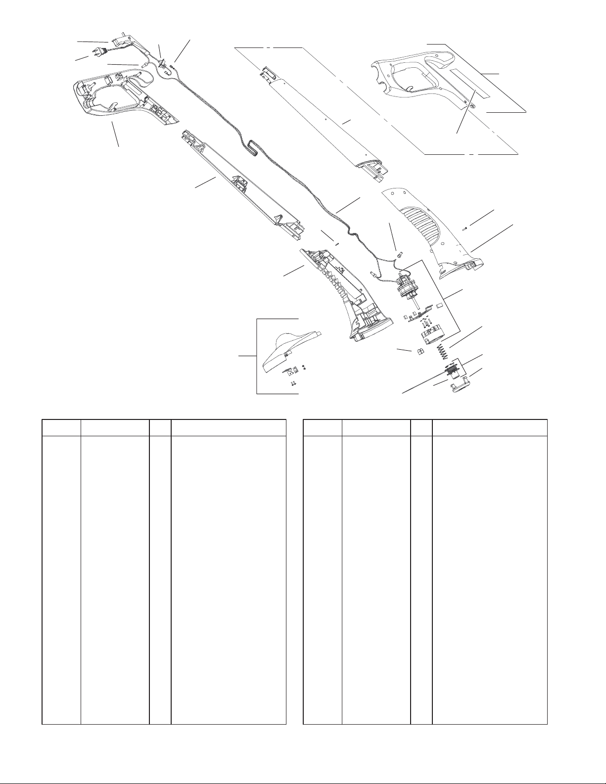
Trimmer Assembly
DescriptionPart No. Qty.Ref. No. DescriptionPart No. Qty.Ref. No.
1 100–9701 1 Handle–LH
3 100–9703 1 Mid–Section, LH
4 100–9704 1 Mid–Section, RH
5 100–9705 1 Housing–Motor, LH
6 100–9706 1 Housing–Motor, RH
9 100–9709 3 Connector–Wire
13 73–8260 1 Eyelet
14 73–8270 1 Spring, Compression
15 73–8250 1 Cap–Small
24 100–9754 1 Wire
26 100–9711 16 Screw
27 100–9712 1 Plug–Input
28 100–9719 1 Trigger–On/Off
29 100–9713 1 Switch
31 100–9755 2 Terminal–Female
33 100–9750 1 Pin–Retaining
38 100–9714 1 Shield ASM
39 100–9715 1 Motor/Drum ASM
40 100–9718 1 Spool ASM
40:1 73–8240 1 Spool
41 100–9720 1 Handle ASM–RH
41:2 100–9700 1 Decal–Serial/Warning
13
40:1
40
n
15
Sheet No.:2
C–2959
2
 Loading...