


ELECTRIC TRIMMER/WEEDER SERVICE MANUAL
Table of Contents – Page 1 of 4
TRIMMER/WEEDER MODELS
FOREWORD
TOOL REQUIREMENTS
AUTOMATIC LIN E FEED ASSEMBLY
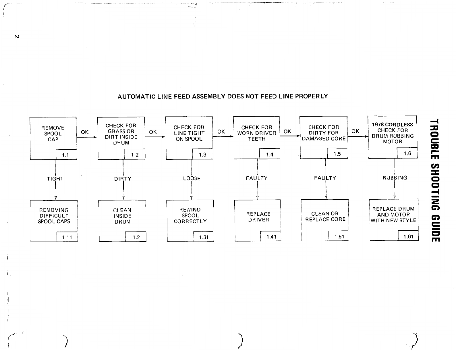
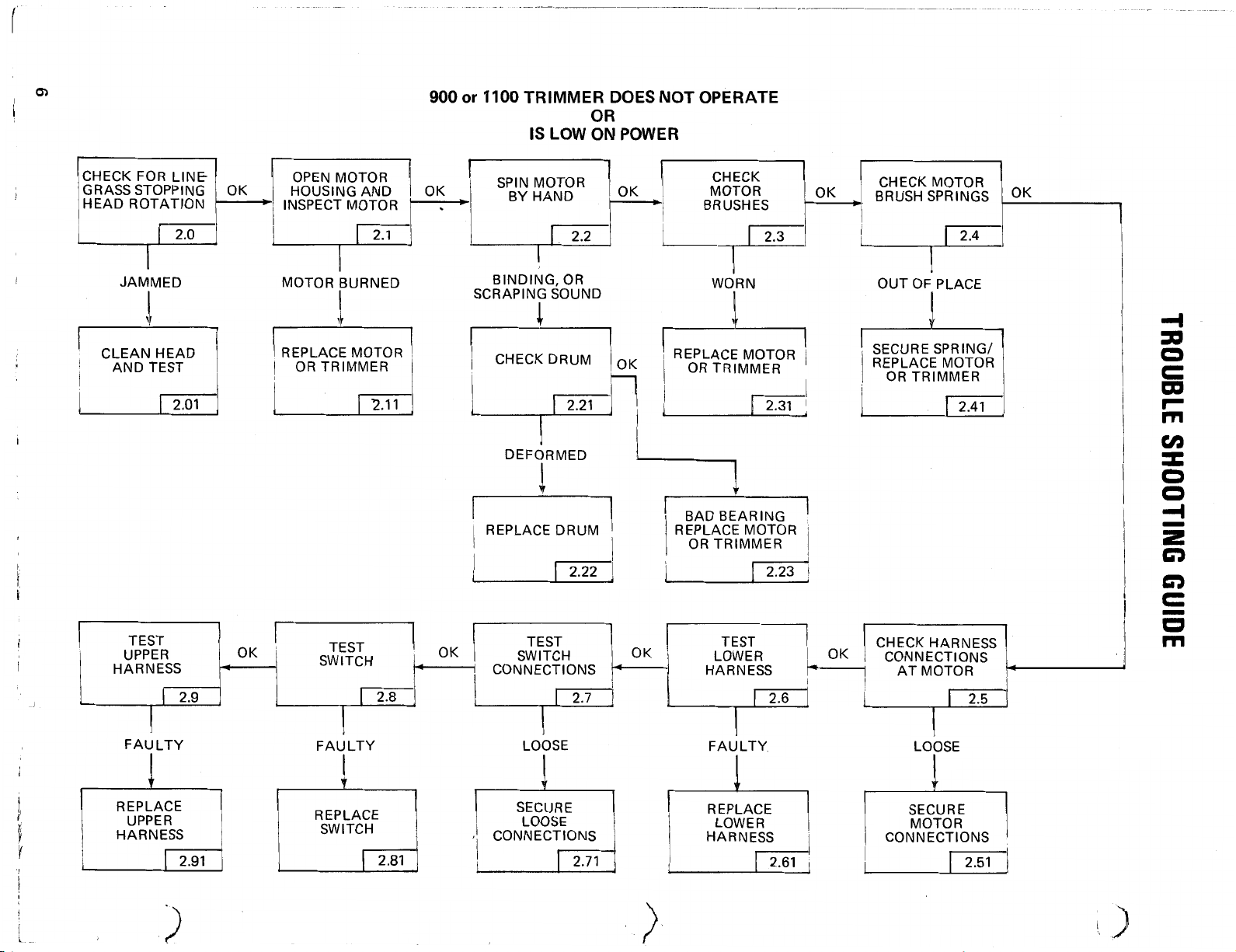
TROUBLE SHOOTING GUIDE
AUTOMATIC LINE FEED ASSEMBLY SERVICE INSTRUCTIONS
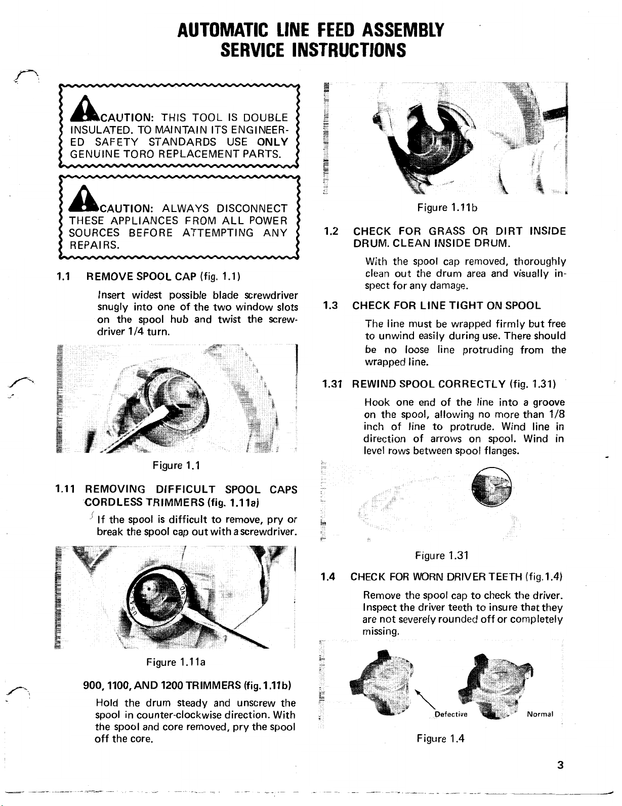
1.1 REMOVE SPOOL CAP (FIG. 1.1)
1.11 REMOVING DIFFICULT SPOOL CAPS CORDLESS TRIMMERS (FIG 1.11A).
900, 1100, AND 1200 TRIMMERS (FIG. 1.11B)
1.2 CHECK FOR GRASS OR DIRT INSIDE DRUM. CLEAN INSIDE DRUM
1.3 CHECK FOR LINE TIGHT ON SPOOL
1.31 REWIND SPOOL CORRECTLY (FIG. 1.31)
1.4 CHECK FOR WORN DRIVER TEETH (FIG. 1.4)
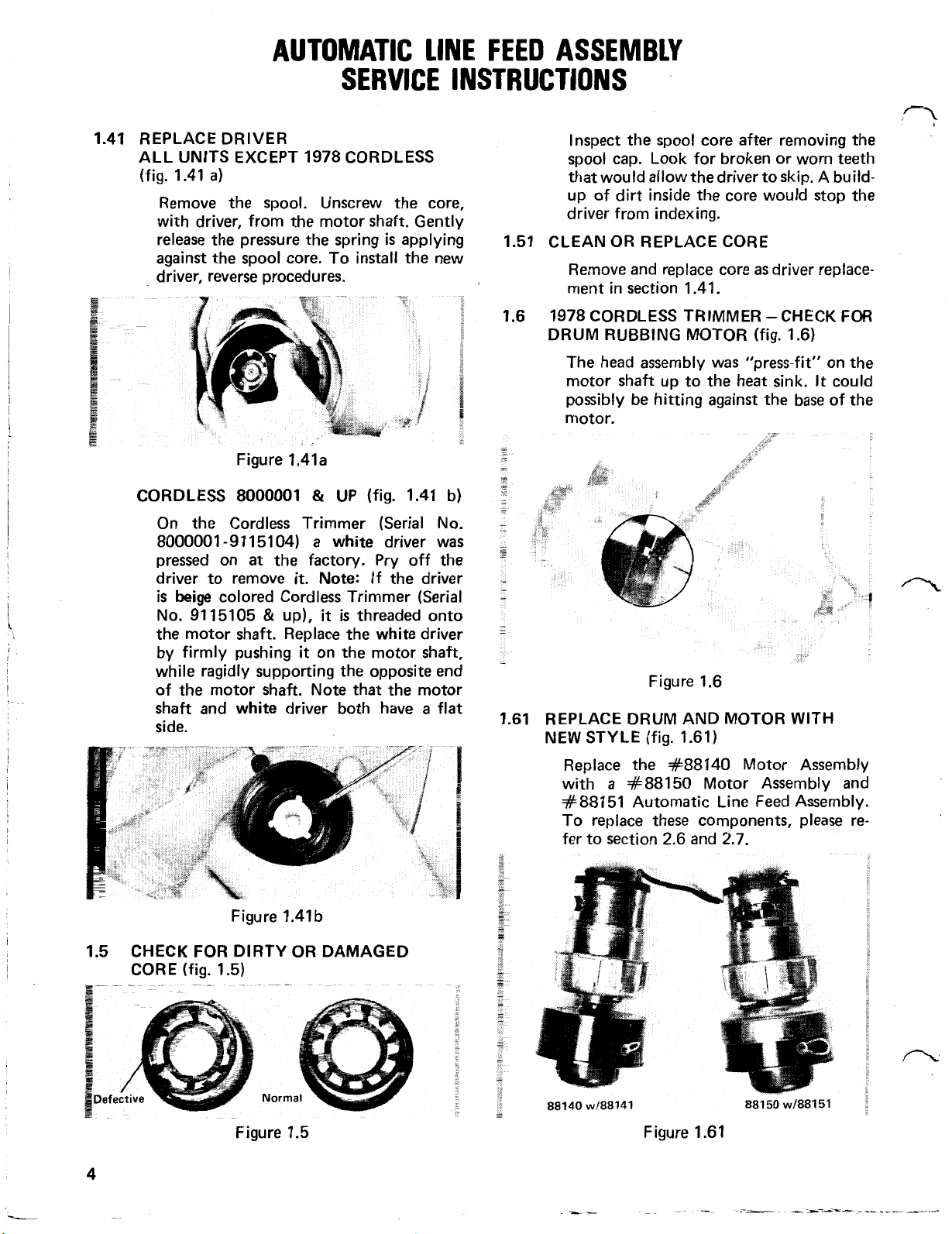
1.41 REPLACE DRIVER ALL UNITS EXCEPT 1978 CORDLESS (FIG. 1.41A)
1.5 CHECK FOR DIRTY OR DAMAGED CORE (FIG. 1.5)
1.51 CLEAN OR REPLACE CORE
1.6 1978 CORDLESS TRIMMER -CHECK FOR DRUM RUBBING MOTOR (FIG.
1.61 REPLACE DRUM AND MOTOR WITH NEW STYLE (FIG. 1.61)
900 AND 1100 TRIMMERS
TROUBLE SHOOTING GUIDE
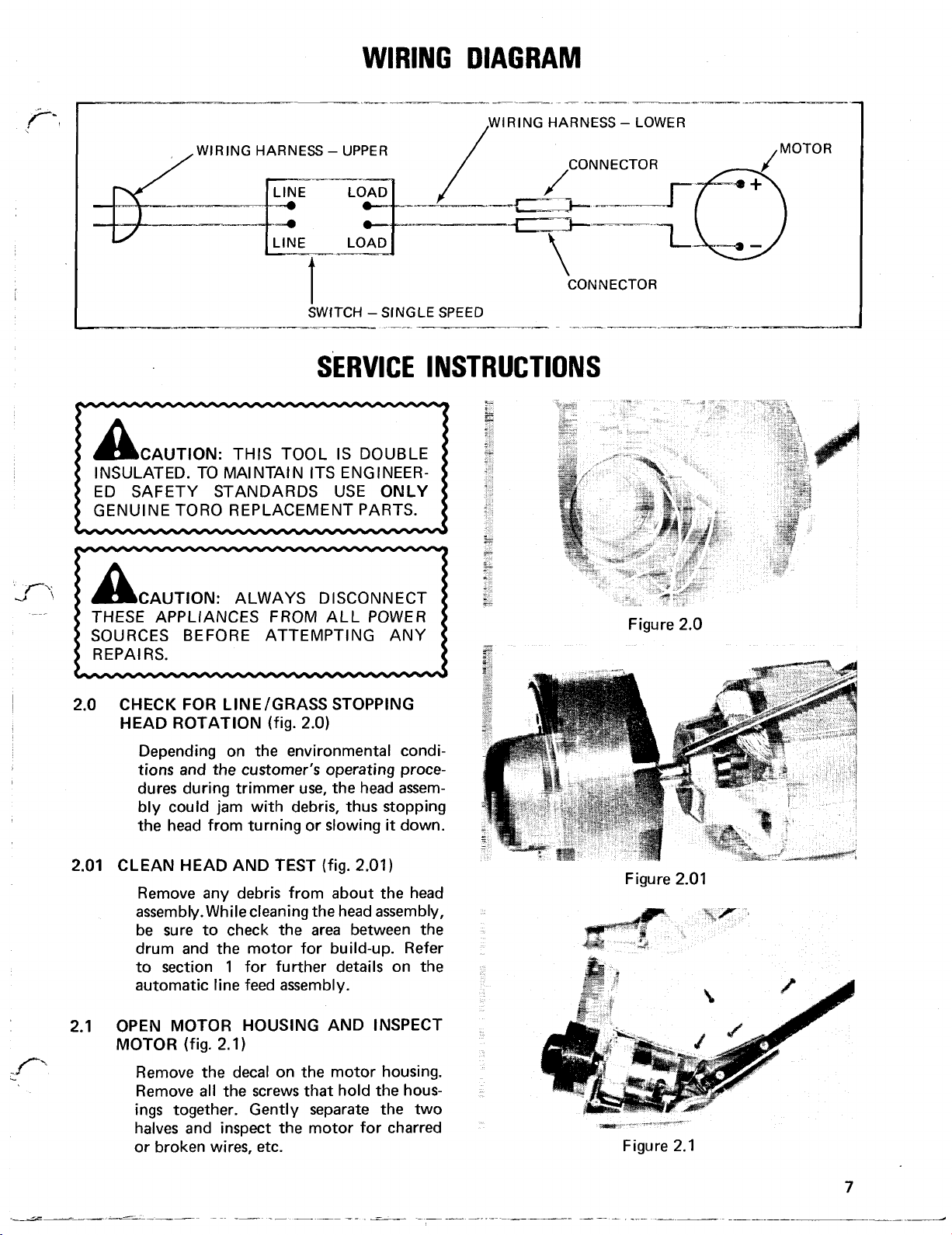
WIRING DIAGRAM
SERVICE INSTRUCTIONS
2.0 CHECK FOR LINE/GRASS STOPPING HEAD ROTATION (FIG. 2.0)
2.01 CLEAN HEAD AND TEST (FIG. 2.01)
2.1 OPEN MOTOR HOUSING AND INSPECT MOTOR (FIG. 2.1)
2.11 REPLACE MOTOR (FIGS. 2.11A, 2.11B)
2.2 SPIN MOTOR BY HAND
2.21 CHECK DRUM (FIG. 2.21)
2.22 REPLACE DRUM (FIG. 2.22) SERIAL NOS. 800001-899999
2.23 BAD BEARING - REPLACE MOTOR OR TRIMMER (FIG. 2.23)
2.3 CHECK MOTOR BRUSHES (FIG. 2.3)
2.31 REPLACE MOTOR OR TRIMMER
2.4 CHECK MOTOR BRUSH SPRINGS (FIG. 2.4)
2.41 SECURE SPRING/REPLACE MOTOR OR TRIMMER (FIG. 2.41)
2.5 CHECK HARNESS CONNECTIONS AT MOTOR
2.51 SECURE CONNECTION AT MOTOR (FIG. 2.51)
2.6 CHECK LOWER HARNESS (FIG. 2.6)
2.61 REPLACE LOWER HARNESS (FIGS. 2.61A, 2.61B)
2.7 TEST SWITCH CONNECTIONS (FIG. 2.7)

ELECTRIC TRIMMER/WEEDER SERVICE MANUAL
Table of Contents – Page 2 of 4
SERVICE INSTRUCTIONS - continued
2.71 SECURE LOOSE CONNECTIONS
2.8 TEST SWITCH (FIGS. 2.8A, 2.8B)
2.81 REPLACE SWITCH (FIG. 2.81)
2.9 TEST UPPER HARNESS (FIG. 2.9)
2.91 REPLACE UPPER HARNESS
1200 TRIMMER
TROUBLE SHOOTING
WIRING DIAGRAM
SERVICE INSTRUCTIONS
3.0 CHECK FOR LINE/GRASS STOPPING HEAD ROTATION (FIG. 3.0)
3.01 CLEAN HEAD AND TEST (FIG. 3.01)
3.1 OPEN MOTOR HOUSING AND INSPECT MOTOR (FIG. 3.1)
3.11 REPLACE MOTOR (FIG. 3.11A, 3.11B)
3.2 SPIN MOTOR BY HAND
3.21 CHECK DRUM (FIG. 3.21)
3.22 REPLACE DRUM (FIG. 3.22) SERIAL NOS. 800001-899999.
3.23 BAD BEARING -- REPLACE MOTOR OR TRIMMER (FIG. 3.23)
3.3 CHECK MOTOR BRUSHES (FIG. 3.3)
3.31 REPLACE MOTOR OR TRIMMER
3.4 CHECK MOTOR BRUSH SPRINGS (FIG. 3.4)
3.41 SECURE SPRING/REPLACE MOTOR OR TRIMMER (FIG. 3.41)
3.5 TEST BRIDGE RECTIFIER (FIG. 3.5A, 3.5B)
3.51 REPLACE BRIDGE RECTIFIER
3.6 CHECK HARNESS CONNECTIONS AT RECTIFIER
3.61 SECURE CONNECTION AT RECTIFIER
3.7 CHECK LOWER HARNESS (FIG. 3.7)
3.71 REPLACE LOWER HARNESS
3.8 TEST SWITCH CONNECTIONS (FIG. 3.8)
3.81 SECURE LOOSE CONNECTIONS
3.9 TEST SWITCH (FIG. 3.9A, 3.9B)
3.91 REPLACE SWITCH (FIG. 3.91)
4.0 TEST UPPER HARNESS (FIG. 4.0)
4.01 REPLACE UPPER HARNESS
CORDLESS TRIMMER
TROUBLE SHOOTING GUIDE
WIRING DIAGRAM

ELECTRIC TRIMMER/WEEDER SERVICE MANUAL
Table of Contents – Page 3 of 4
SERVICE INSTRUCTIONS
5.0 CHECK FOR LINE/GRASS STOPPING HEAD ROTATION (FIG. 5.0)
5.01 CLEAN HEAD AND TEST (FIG. 5.01)
5.1 INSPECT UPPER TO LOWER HARNESS CONNECTION (FIG. 5.1)
5.11 SECURE UPPER TO LOWER HARNESS CONNECTION (FIG. 5.11)
5.2 CHECK BATTERY CONNECTIONS (FIG. 5.2)
5.21 SECURE BATTERY CONNECTIONS
5.3 TEST OUTPUT VOLTAGE OF BATTERY CHARGER (FIG. 5.3)
5.31 REPLACE BATTERY CHARGER
5.4 CHECK CHARGER OUTPUT AT BATTERY CONNECTIONS (FIG. 5.4)
5.41 REPLACE UPPER WIRING HARNESS
5.5 CHARGE BATTERY FOR 48 HOURS AND TEST (FIG. 5.5)
5.51 REPLACE BATTERY AND CHARGE FOR 48 HOURS
5.6 INSPECT MOTOR
5.61 REPLACE MOTOR (FIG. 5.61)
5.7 SPIN MOTOR BY HAND
5.71 CHECK DRUM (FIG. 5.71)
5.72 REPLACE DRUM SERIAL NOS. 800001-9115104
5.73 BAD BEARING - REPLACE MOTOR OR TRIMMER
5.8 CHECK HARNESS CONNECTIONS AT MOTOR
5.81 SECURE MOTOR CONNECTIONS (FIG. 5.81)
5.9 TEST LOWER HARNESS (FIG. 5.9)
5.91 REPLACE LOWER HARNESS
6.0 TEST SWITCH CONNECTIONS
6.01 SECURE LOOSE CONNECTIONS
6.1 TEST SWITCH (FIGS. 6.1A, 6.1B)
6.11 REPLACE SWITCH
6.2 TEST UPPER HARNESS (FIGS. 6.2A, 6.2B)
6.21 REPLACE UPPER HARNESS
6.3 REPLACE MOTOR
PARTS CATALOG
TORO TRIMMER 900 HANDLE ASSEMBLY
PARTS
TORO TRIMMER 900 MOTOR AND HOUSING ASSEMBLY
PARTS
TORO TRIMMER 900 HANDLE ASSEMBLY
PARTS
TORO TRIMMER 900 MOTOR AND HOUSING ASSEMBLY
PARTS
TORO TRIMMER 1100 HANDLE ASSEMBLY
PARTS

ELECTRIC TRIMMER/WEEDER SERVICE MANUAL
Table of Contents – Page 4 of 4
TORO TRIMMER 1100 MOTOR AND HOUSING ASSEMBLY
PARTS
TORO TRIMMER 1100 HANDLE ASSEMBLY
PARTS
TORO TRIMMER 1100 MOTOR AND HOUSING ASSEMBLY
PARTS
TORO TRIMMER 1200 HANDLE ASSEMBLY
PARTS
TORO TRIMMER 1200 MOTOR AND HOUSING ASSEMBLY
PARTS
TORO TRIMMER 1200 HANDLE ASSEMBLY
PARTS
TORO TRIMMER 1200MOTOR AND HOUSING ASSEMBLY
PARTS
TORO CORDLESS TRIMMER UPPER CASE ASSEMBLY
PARTS
TORO CORDLESS TRIMMER MOTOR HOUSING ASSEMBLY
PARTS
TORO CORDLESS TRIMMER UPPER CASE ASSEMBLY
PARTS
TORO CORDLESS TRIMMER MOTOR HOUSING ASSEMBLY
PARTS
OUTDOOR
APPLIANCE
DIVISION
--
Electric
.
I
Trimmer/
SERVICE
Weeder
MANUAL
CORDLESS TRIMMER/WEEDER
900
HOME DUTY TRIMMER/WEEDER
..
.
Model Number 51550
L
Model Numbers 51200
and 51225
1100 HEAVY DUTY TRIMMER/WEEDER
Model Numbers 51300
MARCH
1979
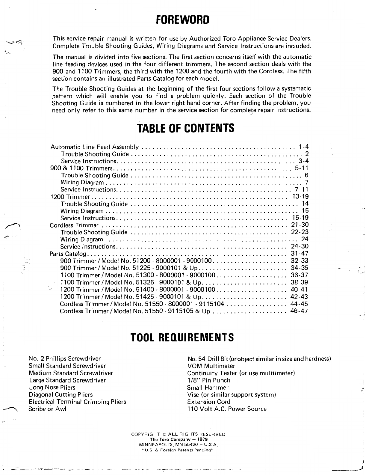
This service repair manual
Complete Trouble Shooting Guides, Wiring Diagrams and Service Instructions are included.
is
The manual
line feeding devices used in the four different trimmers. The second section deals with the
900 and 1100 Trimmers, the third with the 1200 and the fourth with the Cordless. The fifth
section contains an illustrated
The Trouble Shooting Guides
pattern which will enable you to find
Shooting Guide
need only refer to this same number in the service section for complete repair instructions.
divided into five sections. The first section concerns
is
numbered in the lower right hand corner. After finding the problem, you
is
written for use by Authorized Toro Appliance Service Dealers.
itself
with the automatic
Parts
Catalog for each model.
at
the beginning of the first four sections follow a systematic
a
problem quickly. Each section of the Trouble
TABLE
Automatic Line Feed Assembly
Trouble Shooting Guide
Service Instructions.
900
&1100
Trouble Shooting Guide
Wiring Diagram
Service
1200
Trouble Shooting Guide
Wiring Diagram
Service Instructions.
Cordless Trimmer 21-30
Trouble Shooting Guide
Wiring Diagram
Service Instructions.
Parts Catalog
900 Trimmer Model No. 51 200 8000001 9000100. 32-33
900 Trimmer Model No. 51 225
1100 Trimmer/Model No. 51300
1100 Trimmer/Model No. 51325
..
1200 Trimmer/Model No. 51400 . 8000001 . 9000100..
1200 Trimmer
Cordless Trimmer/Model No. 51550
Cordless Trimmer/Model No. 51550
Trimmers
I
Instructions
Trimmer
.......................................................
....................................................
........................................................
/
.................................................
..................................................
.......................................................
................................................
......................................................
...............................................
......................................................
...............................................
Model No. 51425 . 9000101 & Up.
...........................................
................................................
................................................
...............................................
............................................
OF
CONTENTS
. .
.
9000101 & Up.
.
8000001 . 9000100..
.
9000101 & Up.
.
8000001 . 9115104
.
91 15105 & Up
....................
........................
..................
.......................
..................
.......................
..........
.....
.....................
1-4
3-4
5-11
7 . 1 1
13-19
14
15
15-19
22-23
24
24-30
31-47
34-35
36-37
38-39
40-41
42-43
44-45
46-47
2
6
7
No. 2 Phillips Screwdriver
Small Standard Screwdriver
Medium Standard Screwdriver
Large Standard Screwdriver
Long Nose Pliers
Diagonal Cutting Pliers
Electrical Terminal Crimping Pliers
Scribe or Awl
TOOL REQUIREMENTS
No. 54 Drill Bit (or object similar in size and hardness)
VOM Multimeter
Continuity Tester (or use mulitimeter)
1/8" Pin Punch
Small Hammer
(or
similar support system)
1979
-
U.S.A.
COPYRIGHT
The
"US.
Toro
&
Foreign Patents Pending"
MINNEAPOLIS, MN
Vise
Extension Cord
110 Volt A.C. Power Source
ALL
RIGHTS RESERVED
Company
-
55420
AUTOMATIC LINE FEED ASSEMBLY
900
Home Duty
Trimmer/Weeder
Model Numbers 51 200 and
1100
Heavy
Trimmer/ Weeder
Model Numbers 51300 and 51325
1200
Professional
51
225
Duty
Trimmer/Weeder
Model Numbers 51400 and 51425
Cordless
Trimmer/
Model Number 51550
Weeder
1
2
I-
.g-
I-
i
-I
0
I---
--
'
-1
.I
0
0
TROUBLE
SHOOTING
t
>
I-
I-
r
GUIDE
lr'
AUTOMATIC LINE
FEED ASSEMBLY
SERVICE
CAUTION: THIS TOOL
INSULATED. TO MAINTAIN ITS ENGINEERED SAFETY STANDARDS USE ONLY
GENUINE TORO REPLACEMENT PARTS.
THESE APPLIANCES FROM ALL POWER
SOURCES BEFORE ATTEMPTING ANY
REPAlRS.
1.1
REMOVE SPOOL CAP (fig. 1.1)
Insert widest possible blade screwdriver
snugly into one of the two window slots
on the spool hub and twist the screwdriver 1 /4 turn.
IS
DOUBLE
INSTRUCTIONS
I
Figure 1.1 1
CHECK FOR GRASS
1.2
DRUM. CLEAN INSIDE DRUM.
With the spool cap removed, thoroughly
out
clean
spect for any damage.
1.3
CHECK FOR LINE TIGHT ON SPOOL
The line must be wrapped firmly but free
to unwind easily during use. There should
be no loose line protruding from the
wrapped line.
the drum area and visually in-
b
OR
DIRT INSIDE
Figure 1.1
1.11
REMOVING DIFFICULT SPOOL CAPS
.CORDLESS TRIMMERS (fig.
If
the spool
break the spool cap out with
is
difficult to remove, pry or
Figure 1.1
la
l.lla)
a
screwdriver.
1.31
1.4
*-
REWIND SPOOL CORRECTLY (fig. 1.31)
a
Hook one end of the line into
on the spool, allowing no more than 1/8
of
inch
direction of arrows on spool. Wind in
level rows between spool flanges.
CHECK
Remove the spool cap to check the driver.
Inspect the driver teeth to insure that they
are not severely rounded off or completely
missing.
line to protrude. Wind line in
Figure 1.31
FOR
WORN
DRIVER TEETH (fig.l.4)
groove
900,1100,
Hold the drum steady and unscrew the
spool in counter-clockwise direction. With
the spool and core removed, pry the spool
off the core.
AND
1200
TRIMMERS
(fig.
1.11
b)
Figure 1.4
3
1.41 REPLACE DRIVER
ALL UNITS EXCEPT 1978 CORDLESS
(fig. 1.41
Remove the spool. Unscrew the core,
with driver, from the motor shaft. Gently
release the pressure the spring
against the spool core. To install the new
driver, reverse procedures.
a)
SERVICE
is
applying
INSTRUCTIONS
Inspect the spool core after removing the
spool cap. Look for broken or worn teeth
that would allow the driver to skip. A build-
of
up
driver from indexing.
dirt inside the core would stop the
1.51 CLEAN OR REPLACE CORE
Remove and replace core
ment in section 1.41.
as
driver replace-
1.6 1978 CORDLESS TRIMMER -CHECK FOR
DRUM RUBBING MOTOR
The head assembly was "press-fit" on the
motor shaft up to the heat sink.
possibly be hitting against the base of the
motor.
(fig.
.
1.6)
It
could
,-
Figure 1.41
CORDLESS 8000001 & UP
On the Cordless Trimmer (Serial No.
8000001-9115104)
pressed on
driver to remove
is
beige colored Cordless Trimmer (Serial
No. 9115105
the motor shaft. Replace the white driver
by firmly pushing
while rigidly supporting the opposite end
of the motor shaft. Note that the motor
shaft and white driver both have
side.
at
&
a
(fig.
1.41
a
white driver was
the factory. Pry off the
it.
Note: If the driver
up),
it
is
threaded onto
it
on the motor shaft,
a
b)
flat
Figure
1.6
1.61 REPLACE DRUM AND MOTOR WITH
(fig.
NEW STYLE
Replace the
a
with
# 88151 Automatic Line Feed Assembly.
To replace these components, please refer to section
# 88150 Motor Assembly and
1.61)
# 88140
2.6
and
Motor Assembly
2.7.
Figure 1.41 b
1.5 CHECK FOR DIRTY OR DAMAGED
(fig.
CORE
1.5)
Figure 1.5
4
88140~188141 88150w/88151
Figure
1.6
1

900
Home
Duty
Trimmer/ Weeder
Model Numbers 51200 and 51225
and
1100
Heavy
Duty
Trimmer/ Weeder
Model Numbers 51300 and 51325
I-
TROUBLE SHOOTING GUIDE
WIRING
-
WIRING HARNESS
UPPER
SWfTCH -SINGLE SPEED
.
SERVICE INSTRUCTIONS
INSULATED. TO MAINTAIN ITS ENGINEERED SAFETY STANDARDS USE
GENUINE TORO REPLACEMENT PARTS.
ONLY
DIAGRAM
IRING HARNESS - LOWER
CONNECTOR
CONNECTOR
I
THESE APPLIANCES FROM ALL POWER
SOURCES BEFORE ATTEMPTING ANY
2.0 CHECK
HEAD ROTATION
2.01 CLEAN HEAD AND TEST
assembly. While cleaning the head assembly,
drum and the motor for build-up. Refer
to section 1 for further details on the
automatic line feed assembly.
2.1 OPEN MOTOR HOUSING AND INSPECT
MOTOR
FOR
LINE/GRASS STOPPING
(fig. 2.0)
Depending on the environmental condi-
the
tions and
dures during trimmer use, the head assem-
bly could jam with debris, thus stopping
the head from turning or slowing
Remove any debris from about the head
be sure to check the
(fig. 2.1)
customer’s operating proce-
it
down.
(fig. 2.01)
area
between the
Figure 2.0
Figure 2.0 1
Remove the decal on the motor housing.
all
Remove
ings together. Gently separate the
halves and inspect the motor for charred
or broken wires, etc.
the screws that hold the hous-
two
7
2.1
REPLACE
MOTOR
(figs. 2.1
SERVICE
la,
2.1lb)
INSTRUCTIONS
When replacing the motor
to remove the automatic line feed assembly. Refer to section 1 for head disassem-
To
bly.
wire cutters and nip the connector in the
center of the factory crimp; pull the wires
out. Remove the roll pin by rigidly supporting the armature shaft (to prevent
bending) and driving the roll pin out.
remove the wire connectors, use
Figure 2.11a
it
is
necessary
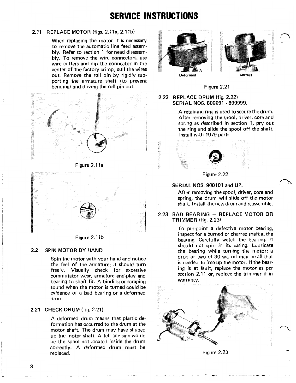
2.22
Deformed
Figure 2.21
REPLACE DRUM
SERIAL
A
After removing the spool, driver, core and
spring
the ring and slide the spool off the shaft.
Install with 1979 parts.
SERIAL
After removing the
spring, the drum will slide off the motor
shaft. Install the new drum and reassemble.
NOS.
retaining ring
as
described in section 1, pry out
NOS.
(fig.2.22)
800001
is
used to secure the drum.
Figure 2.22
900101
spool,
and
Correct
-
899999.
UP.
driver, core and
CYA
Figure 2.1 1 b
2.2 SPIN MOTOR BY HAND
Spin the motor with your hand and notice
the feel of the armature;
freely. Visually check for excessive
commutator wear, armature end-play and
bearing to shaft fit. A binding or scraping
sound when the motor
a
evidence of
drum.
2.21 CHECK DRUM
A deformed drum means that plastic deformation has occurred to the drum
motor shaft. The drum may have slipped
up the motor shaft. A
be the spool not located inside the drum
correctly. A deformed drum must be
replaced.
bad bearing or a deformed
(fig. 2.21)
it
should turn
is
turned could be
tell-tale
sign would
at
the
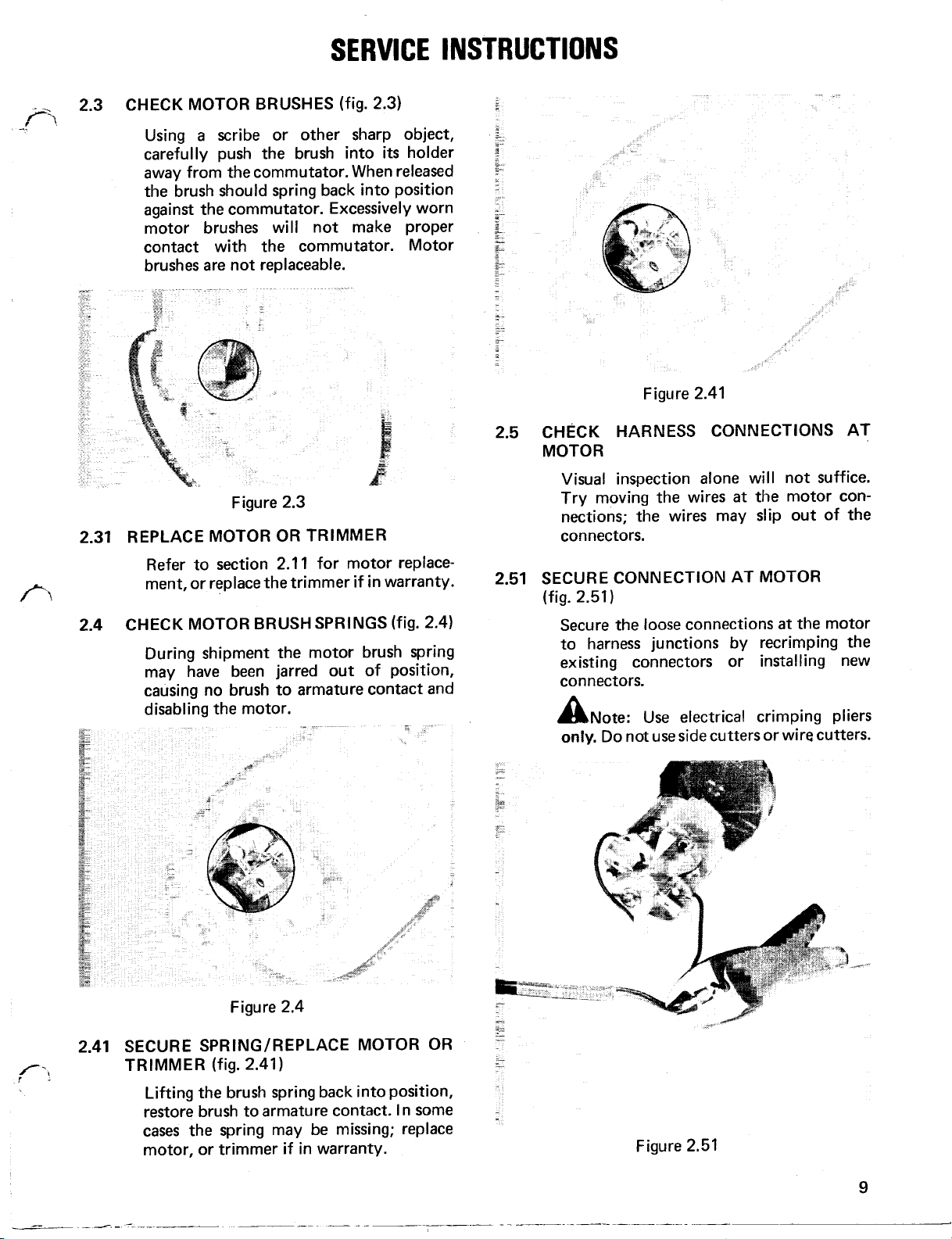
2.23 BAD BEARING
TRIMMER
To pin-point
inspect for
bearing. Carefully watch the bearing.
should not spin in
the bearing while turning the motor;
drop or two of 30 wt. oil may be
is
needed to free-up the motor. If the bearing
section 2.1
warranty.
is
at
(fig. 2.23)
-
REPLACE MOTOR OR
a
defective motor bearing,
a
burned or charred shaft
its
casing. Lubricate
fault, replace the motor
1
or, replace the trimmer if in
Figure 2.23
at
all
as
the
It
a
that
per
8
SERVICE INSTRUCTIONS
2.3
CHECK MOTOR BRUSHES
Using
carefully push the brush into
away from the commutator. When released
the brush should spring back into position
against the commutator. Excessively worn
motor brushes will not make proper
contact with the commutator. Motor
brushes are not replaceable.
2.31 REPLACE MOTOR OR TRIMMER
a
scribe or other sharp object,
Figure 2.3
(fig. 2.3)
its
holder
Figure 2.41
2.5 CHECK HARNESS CONNECTIONS AT
MOTOR
Visual inspection alone will not suffice.
at
Try moving the wires
nections; the wires may slip out of the
connectors.
the motor con-
Refer to section 2.1 1 for motor replace-
ment, or replace the trimmer if in warranty.
2.4 CHECK MOTOR BRUSH SPRINGS
During shipment the motor brush spring
may have been jarred out of position,
causing no brush to armature contact and
disabling the motor.
Figure
2.4
(fig. 2.4)
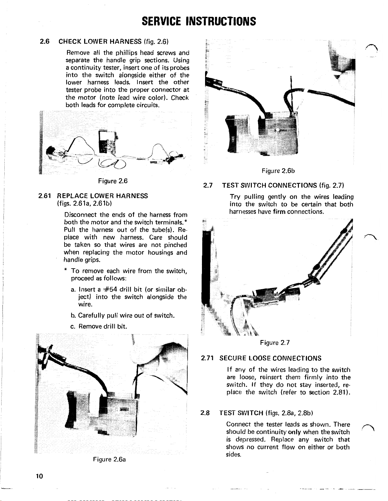
2.51 SECURE CONNECTION AT MOTOR
(fig. 2.51)
Secure the loose connections
to harness junctions by recrimping the
existing connectors or installing new
connectors.
Note:Use
! A
only,
Do not use side cutters or wire cutters.
electrical crimping pliers
at
the motor
2.41 SECURESPRING / REPLACEMOTOR OR
TRIMMER
Lifting the brush spring back into position,
restore brush to armature contact. In some
cases
motor, or trimmer if in warranty.
(fig.
2.41)
the spring may be missing; replace
Figure 2.51
9
2.6
CHECK LOWER HARNESS
SERVICE
(fig. 2.6)
INSTRUCTIONS
2.61
Remove
separate the handle grip sections. Using
a
continuity tester, insert one of
into the switch alongside either of the
lower harness leads. Insert the other
tester probe into the proper connector
the motor (note lead wire color). Check
both leads for complete circuits.
all
the Phillips head screws and
Figure 2.6
its
probes
REPLACE LOWER HARNESS
(figs. 2.61 a, 2.61b)
Disconnect the ends
both the motor and the switch terminals.*
Pull the harness out of the tube(s).
place with new harness. Care should
so
be taken
when replacing the motor housings and
handle grips.
that wires are not pinched
of
the harness from
at
Re-
Figure 2.6b
2.7
TEST SWITCH CONNECTIONS
Try pulling gently on the
into the switch to be certain that both
(fig.
2.7)
w
wires leading
*
To remove each wire from the switch,
proceed
a.
b. Carefully pull wire out of switch.
c.
as
follows:
Insert
ject) into the switch alongside the
wire.
Remove drill bit.
a
#54
drill bit (or similar ob-
Figure 2.6a
2.71
2.8
Figure 2.7
SECURE LOOSE CONNECTIONS
If any of the wires leading to the switch
are loose, reinsert them firmly into the
switch. If they do not stay inserted, replace the switch (refer to section 2.81).
TEST SWITCH
Connect the tester leads
should be continuity
is
depressed. Replace any switch that
shows no current flow on either or both
sides.
(figs. 2.8 a, 2.8b)
as
only
when the switch
shown. There
10

SERVICE
INSTRUCTIONS
WARNING: FORCING
SWITCH MAY CAUSE INTERNAL DAMAGE.
DO NOT INSERT OBJECTS LARGER THAN
1/32 INCH DIAMETER INTO SWITCH.
Figure
PROBES
2.8a
INTO THE
2.9
TEST UPPER HARNESS
Insert one probe of
into the switch alongside either harness
lead. Connect the other terminal of the
tester to the proper spade of the harness.
Test both leads for complete circuits.
Figure 2.8 1
(fig.
2.9)
a
continuity tester
2.81
Figure 2.8b
REPLACE SWITCH (fig. 2.81)
Install the new switch after replacing the
wires in their proper terminals (refer
the trimmer wiring schematic). Correctly
position the switch in the handle grip.
as
Care should be taken
wires when securing the handle grips.
not to pinch any
to
2.91
Figure 2.91
REPLACE UPPER HARNESS
After removing the wires from the switch
(see
*
in section 2.611, install the new up-
per wiring harness by replacing the wires
in the proper terminals of the switch.
Position the harness in the handle grips.
so
Caution should be taken
are not pinched when securing the handle
grips.
that the wires

1200
Professional
Trimmer/ Weeder
Model
Numbers
51400
and
51425

'I
0
,!-I
0
I-
O
5
a
k
5
2
3-
>
1
0
3
-u4
a
0
I-
J
I
'I--
0
TROUBLE
--f
'ri
n
a
w
SHOOTING
9
'
LL
a
3-
5
t
4
s
-
0-
v)
w

WIRING DIAGRAM
WIRING HARNESS - UPPER
SWITCH-TWOSPEED
MOTOR
R
BRIDGE
WIRING HARNESS - LOWER
SERVICE INSTRUCTIONS
INSULATED. TO MAINTAIN ITS ENGINEER-
ED SAFETY STANDARDS USE
THESE APPLIANCES FROM ALL
SOURCES
3.0
CHECK
HEAD ROTATION
BEFORE
FOR
ATTEMPTING ANY
LINE/GRASS STOPPING
(fig.
3.0)
POWER
RECTIFIER
ONLY
Figure
3.0
Depending on the environmental conditions and the customer‘s operating procedures during trimmer use, the head
assembly could jam with debris, thus
stopping the head from turning or slowing
it
down.
3.01 CLEAN HEAD AND TEST
Remove any debris from about the head
While
assembly.
be sure to check the area between the drum
and the motor for build-up. Refer to
section 1 for further details on the automatic line feed assembly.
cleaning the head assembly,
(fig.
3.01)
3.1 OPEN MOTOR HOUSING AND INSPECT
MOTOR
Remove the decal on the motor housing.
Remove
ings together. Gently separate the two
halves and inspect the motor for charred
or broken wires,
(fig.
all
the screws that hold the hous-
etc.
.
Figure
Figure
3.01
3.1
15

SERVICE INSTRUCTIONS
3.11
REPLACE MOTOR
When replacing the motor
to remove the automatic line feed assembly.
Refer to section
To
remove the wire connectors, use wire
cutters and nip the connector in the center
of the factory crimp; pull the wires out.
Remove the roll pin by rigidly supporting
the armature shaft (to prevent bending)
and driving the roll pin out.
Figure 3.1
(fig. 3.1
1
la,
3.1 1b)
it
is
necessary
for head disassembly.
la
3.22
REPLACE DRUM
SERIAL NOS.
-
Deformed
Figure 3.21
(fig. 3.22)
800001 -899999.
is
A retaining ring
After removing the spool, driver, core and
as
spring
the ring and slide the spool off the shaft.
Install with 1979 parts.
described in section 1, pry out
used to secure the drum.
Correct
3.2
SPIN MOTOR
Spin the motor with your hand and notice
the feel of the armature;
freely. Visually check for excessive commutator wear, armature end-play and bearing to shaft
when the motor
of
CHECK DRUM
3.21
A deformed drum means that plastic de-
formation has occurred to the drum
motor shaft. The drum may have slipped
up the motor shaft. A
be the spool not located inside the drum
correctly. A deformed drum must be
replaced.
Figure 3.1 1 b
BY
HAND
it
should turn
fit.
A binding or scraping sound
is
turned could be evidence
a
bad bearing or a deformed drum.
(fig. 3.21)
tell-tale
sign would
at
the
Figure 3.22
SERIAL NOS.
After removing the spool, driver, core and
spring, the drum will slide off the motor
shaft. Install the new drum and reassemble.
BAD BEARING - REPLACE MOTOR
3.23
TRIMMER
To pin-point
inspect for
the bearing. Carefully watch the bearing;
it
should not spin in
the bearing while turning the motor;
drop or two of 30 wt. oil may be
is
needed to free-up the motor.
bearing
section 2.1
in warranty.
900101 and
(fig.
3.23)
a
defective motor bearing,
a
burned or charred shaft at
its
is
at
fault, replace the motor
1
or, replace the trimmer if
Figure 3.23
UP.
OR
casing. Lubricate
all
that
If
the
as
per
a
16

3.3
SERVICE
CHECK MOTOR BRUSHES
a
Using
carefully push the brush into
away from the commutator. When re-
leased the brush should spring back into
position against the commutator. Excessively worn motor brushes will not make
proper contact with the commutator.
Motor brushes
scribe or other sharp object,
are
not replaceable.
(fig.
3.3)
its
INSTRUCTIONS
3.41
SECURE SPRING/
TRIMMER
holder
3.5
Lifting the brush spring back into position,
restore brush to armature contact.
cases the spring may be missing; replace
motor or, trimmer
TEST BRIDGE RECTIFIER
REPLACE
(fig. 3.41)
Figure 3.41
if
in
MOTOR OR
warranty.
(fig. 3.5a, 3.5b)
In
some
Figure 3.3
3.31 REPLACE MOTOR
Refer to section 2.1 1 for motor replace-
ment, or replace the trimmer
3.4
CHECK MOTOR BRUSH
During shipment the motor brush spring
may have been jarred out of position,
causing no brush to armature contact
and disabling the motor.
OR
TRIMMER
SPRINGS
if
in warranty.
(fig.
3.4)
The readings obtained during the following
test
will vary depending on the
ment and settings used.
adjacent terminals on the rectifier
combinations will be tested), connect
the
tester
Reverse the leads. Again, note the reading.
Continue this
terminals have been checked (4
after any
2nd reading, the rectifier
must be replaced.
to them and note the reading.
test
process until
test
the 1st reading equals the
test
Select
is
faulty and
equip-
any
two
(all
all
the
tests).
If
Figure 3.4
Figure 3.5a
17

SERVICE
INSTRUCTIONS
3.51
3.6
Figure 3.5b
REPLACE BRIDGE RECTIFIER
Careful attention must be paid to replacing
the wires in the proper position.
schematic. Trimmers with serial number
9000101
harness replaced.
CHECK HARNESS CONNECTIONS AT
RECTIFIER
Visual inspection alone will not suffice.
Try moving the wires
connections; the wires may slip out of the
terminals.
and up must have the lower wire
at
See
wiring
the rectifier
Figure
3.71 REPLACE LOWER HARNESS
Disconnect the ends of the harness from
both the rectifier and the switch terminals
(see
sections
ness out of the tubes. Replace with new
harness. Caution should be taken
wires are not pinched when replacing the
motor housings and handle grips.
3.8
TEST SWITCH CONNECTIONS
Try pulling gently on the wires leading into the switch to be certain that both har-
3.1
1
3.7
and
2.61).
Pull the har-
so
that
(fig.
3.8)
SECURE CONNECTION AT RECTIFIER
3.61
Secure the loose connections
rectifier or replace the lower harness.
! Note: Use electrical crimping pliers
Do
only.
CHECK LOWER HARNESS
3.7
Remove
separate the handle grip sections. Using
a
probes into the switch along either of the
lower harness leads.
probe onto the proper terminal
rectifier (note lead wire color). Check both
leads for complete circuits.
not use side cutters or wire cutters.
all
continuity tester, insert one of
at
(fig.
3.7)
the phillips head screws and
Place
the other tester
at
the
its
the
Figure
3.81 SECURE LOOSE CONNECTIONS
If any of the wires leading to the switch
are loose, reinsert them firmly into the
switch.
place the switch (refer to section
If
they do not stay inserted, re-
3.8
2.81
).

SERVICE
DO
NOT INSERT OBJECTS LARGER THAN
1/32 INCH DIAMETER INTO SWITCH.
3.9
TEST SWITCH
(figs.
3.9 a, 3.9b)
INSTRUCTIONS
wires in their proper terminals (refer
to the trimmer wiring schematic). Correctly position the switch in the handle
grip. Care should be taken
pinch any wires when securing the handle
grips.
as
not to
THE
SPEED SWITCH. Disconnect
the switch
the tester leads
continuity
pressed. Replace any switch that shows
no current flow on either or both sides.
1200
NOTE:
pending on
other
does not have
replace the switch.
tests
TRIMMER USES A TWO
all
(see
*
in section 2.61). Connect
as
shown. There should be
only
when the switch
The
test
readings may vary de-
test
equipment used. If
are good and the trimmer
a
high and low speed,
lines to
is
de-
all
Figure 3.91
TEST UPPER HARNESS
Insert one probe of a continuity tester
into the switch alongside either harness
lead. Connect the other terminal of the
tester to the proper spade of the harness.
Test both leads for complete circuits.
(fig.
4.0)
3.91
Figure 3.9b
REPLACE SWITCH
Install the new switch by replacing the
(fig. 3.91)
4.01
Figure
4.0
REPLACE UPPER HARNESS
After removing the wires from the switch
(see
*
in section 2.61), install the new up-
per wiring harness by placing the wires in
the proper terminals of the switch. Position
the harness in the handle grips. Caution
so
should be taken
pinched when securing the handle grips.
that the wires are not
19

Cordless
Trimmer/ Weeder
Model
Number
51550

22
-t
0
8
I-
l-
CT
W
a
W
--
-L
0
TROUBLE SHOOTING GUIDE
L
,-.
.
-
I

r
n
K
TROUBLE SHOOTING GUIDE
yI
0
z
3
23
I
E
W
n
L
W
n
I
a
W

WIRING
DIAGRAM
.
UPPER
WIRING
HARNESS
SERVICE
CAUTION:
INSULATED. TO MAINTAIN ITS ENGINEERED SAFETY STANDARDS USE
THIS TOOL
IS
DOUBLE
ONLY
MOTOR
.
INSTRUCTIONS
CAUTION:
THESE APPLIANCES FROM ALL
I
SOURCES
CHECK FOR LINE/GRASS STOPPING
5.0
HEAD ROTATION
CLEAN HEAD AND TEST
5.01
5.1
INSPECT UPPER TO LOWER HARNESS
CONNECTION
assembly. While cleaning the head assemdrum and the motor for build-up. Refer
to section 1 for further details on the
automatic line feed assembly.
BEFORE
Depending on the environmental conditions and the customer's operating procedures during trimmer use, the head
assembly could jam with debris, thus
stopping the head from turning or slow-
it
down.
ing
Remove any debris from about the head
bly, be sure to check the area between the
ALWAYS DISCONNECT
ATTEMPTING ANY
(fig. 5.0)
(fig. 5.1)
POWER
(fig. 5.01)
Figure 5.0
Figure 5.01
24
Remove red cover from power pack
by inserting a wide blade screw driver
between the black handle and red cover
as
on both sides
Lift cover forward, then up. The upper to
lower harness connection should be secure.
shown and twist gently.
case
Figure 5.1

SERVICE
INSTRUCTIONS
5.11 SECURE UPPER
\
CONNECTION
Check that the connection
or corrosion. If reconnecting had no
effect, unplug the connector, clean the
terminals and retest the trimmer. If any
of the wires or connectors are damaged,
refer to section 5.41 for upper wire harness replacement.
TO
(fig. 5.1
Figure 5.1
LOWER HARNESS
1
)
1
5.2 CHECK BATTERY CONNECTIONS
The battery connections should be free of Figure 5.3
dirt and corrosion. Insure that each bat-
is
tery lead wire
proper battery terminal.
NOTE:
(red wire).
The largest terminal
firmly in place on the
is
free of dirt
(fig.
5-2)
5.31 REPLACE BATTERY CHARGER
a
Replace
is
positive TORO charger, part # 33-6730.
5.4
CHECKCHARGER OUTPUT ATBATTERY
CONNECTIONS
faulty charger with a genuine
(fig. 5.4)
Figure
5.2
5.21 SECURE BATTERY CONNECTIONS
Plug each battery lead wire
place on the appropriate battery ter-
minal.
NOTE:
(red wire). If securing them did not repair
the trimmer, clean the battery terminals
and retest the trimmer. In the event that
any of the wires or connectors are damaged,
refer to section 5.41 for upper wire harness replacement.
The largest terminal
5.3 TEST OUTPUT VOLTAGE
CHARGER
Test the charger with a voltmeter.
tester for
voltmeter leads to the charger wires
shown. Plug the charger into
outlet (make sure switched outlets are on)
and read the charger output on the voltmeter scale.
least
(fig. 5.3)
a
10
V.D.C.
A
good charger will show
5.0
volts D.C. output.
OF
test.
firmly
is
BATTERY
Connect the
a
110
in
positive
Set
the
as
volt
at
Disconnect battery leads from battery.
Plug the battery charger into the receptacle
on the bottom of the battery case and into
a
110 volt outlet (make sure switched
a
outlets are turned on). Using
set
meter
the negative voltmeter lead to the small
battery terminal. The charger output indicated on the voltmeter
ceed
for a 10 V.D.C.
5.0
volts.
Figure 5.4
test,
scale
volt-
connect
must ex-
25

SERVICE
INSTRUCTIONS
E.
Remove
5.41 d).
the
battery pack
(fig.

SERVICE
H.
Replace the wiring harness (fig.
5.41f).
INSTRUCTIONS
c.
Insert the short end of the
spring into the hole in the
trigger release. The coil of
the spring must
plastic boss in the case (fig.
5.41i).
fit
over the
Figure 5.41f
To
save
I.
be tested
tion
To replace the trigger release, trigger
J.
and spring, proceed
a.
time later, the switch should
at
this point. Refer to
2.8
for procedures.
as
follows:
Note that on the inside of the
trigger release there
hole. This hole accepts the short
end of the spring (fig. 5.419g).
Figure 5.41g
is
a
sec-
small
Figure 5.41
d.
Place
end of the spring. Put the trig-
boss
ger
case.
ger in this position and
the spring and trigger release
(Fig. 5.41 j ) .
Figure 5.41
e.
Place the remaining half of the
battery case over the trigger
mechanism, assuring the charging receptacle
the case halves
i
the trigger over the long
into the hole in the
Carefully hold the trig-
j
is
in place. Secure
(fig.
5.41 k).
let
go of
b. Lay
the
left half of the battery
case
on a work bench in a steady
position and install the trigger
release in position
Figure 5.41 h
(fig.
5.41h).
Figure 5.41
k
27

SERVICE
INSTRUCTIONS
5.5 CHARGE BATTERY FOR 48 HOURS AND
TEST
(fig. 5.5)
To
test
the Power Pack, the battery must
be in place and connected inside the trim-
a
mer. Connect
V.D.C.
large terminal
With the trimmer cutting head in
position, squeeze the trigger and read the
voltmeter
means that the battery
should be replaced.
test)
scale.
voltmeter
to the battery wiring harness;
is
positive, small
A reading below 6 volts
(set
for a 10
is
negative.
is
defective and
a
safe
Figure 5.61
5.7 SPIN MOTOR BY HAND
Spin the motor with your hand and notice
the feel of the armature;
freely. Visually check for excessive commutator wear, armature end-play and bearing to shaft fit. A binding or scraping sound
is
when the motor
idence of a bad bearing or a deformed
drum.
turned could be
it
should turn
ev-
I
Figure 5.5
5.51 REPLACE BATTERY AND CHARGE FOR
48 HOURS
After removing the battery
section 5.41 (steps A,
the new battery in reverse order.
DON’T FORGET:
for
48
hours before putting
5.6 INSPECT MOTOR
Remove
ings together. Gently separate the two
halves and inspect the motor for charred
or broken wires,
all
the screws that hold the hous-
5.61 REPLACE MOTOR
When replacing the motor
to remove the automatic line feed assem-
bly. Refer to section
To
bly.
wire cutters and nip the connector in the
center of the factory crimp; now pull the
wires out.
remove the wire connectors, use
Charge the new battery
etc.
(fig. 5.61)
as
outlined in
C,
D,
E),
it
to use!
it
is
necessary
1
for head disassem-
install
5.71 CHECK DRUM
A deformed drum means that plastic deformation has occurred to the drum
motor shaft. The drum may have slipped
up the motor shaft.
be the
correctly. When the drum
it
must be replaced.
(fig. 5.71)
spool
not located inside the drum
Figure 5.71
5.72 REPLACE DRUM
SERIAL NOS. 800001-91 15104
After removing the spool, driver, core and
as
spring
spool off the shaft. Note that the motor
shaft has
drum.
described in section
a
flat side to line up inside the
A
tell-tale
at
sign would
is
deformed
1,
pry the
--
the
28

SERVICE INSTRUCTIONS
SERIAL NOS. 9115105 & UP
After removing the spool, driver, core and
spring, the drum will slide off the motor
shaft. Install the new drum and reassemble.
5.73
5.8
5.81
BAD BEARING - REPLACE MOTOR OR
TRIMMER
To pin-point a defective bearing, inspect
a
burned or charred shaft
for
Carefully watch the bearing;
spin in
while turning the motor;
oil
the motor.
place the motor
replace the trimmer if in warranty.
CHECK HARNESS CONNECTIONS AT
MOTOR
Visual inspection alone will not suffice.
Try moving the wires
tions; the wires may slip out of the con-
nectors.
SECURE MOTOR CONNECTIONS
(fig. 5.81)
Secure the loose connections
by recrimping the existing connectors or
installing new ones.
! Note:
only.
its
casing. Lubricate the bearing
may
be
all
that
is
If
the bearing
as
per section 2.1 1, or
at
use
electrical crimping pliers
Do not use side cutters or wire cutters.
at
the bearing.
it
should not
a
drop of
needed to free-up
is
the motor connec-
at
30
at
fault, re-
the motor
wt.
Figure 5.9
REPLACE LOWER HARNESS
To replace lower harness, disconnect the
upper to lower harness. Cut the motor
at
terminals
wires out. Pull the harness out of the tube.
Install the new harness. Caution should be
taken
replacing the motor housings.
TEST SWITCH CONNECTIONS
Pull gently on the wires leading into the
switch to be certain of firm connections.
SECURE LOOSE CONNECTIONS
If
any of the wires leading to the switch
are loose, re-install them firmly onto the
switch. If they do not stay
squeeze the wire terminals with pliers
to close the ears of the terminal.
TEST SWITCH
Open the battery
tion 5.41. Disconnect the wires on the
switch. Connect the -tester leads
and activate the switch. There should be
continuity only when the switch
pressed.
the factory crimp and pull the
so
that wires are not pinched when
on,
carefully
(figs. 6.1a, 6.1b)
case
as
described in sec-
as
shown
is
de-
Figure 5.81
5.9 TEST LOWER HARNESS
With the battery cover off, unplug the
upper to lower harness. Insert one of the
probes of a continuity tester into either
of the lower harness leads. Insert the
other tester probe into the proper con-
at
nector
color). Check both leads for complete
circuits.
the motor (note lead wire to
(fig. 5.9)
Figure 6.1a

SERVICE
INSTRUCTIONS
h
Figure 6.2a
Figure 6.1 b
6.11 REPLACE SWITCH
Install the new switch by replacing the
wires on the terminals (refer to the trim-
mer wiring schematic). Correctly position
the switch in the handle grip. Care should
as
be taken
securing the handle grips.
5.41 for case assembly.
6.2 TEST UPPER HARNESS
Remove the battery cover. Disconnect both
battery terminals and the upper to lower
harness connection.
(Test 1) Using
a
probe into the upper harness connector
(red wire). Connect the other lead
tester to the red wire battery terminal.
Activate the switch. The tester should
show continuity.
not to pinch any wires when
a
continuity tester, insert
(figs.
See
section
6.2a, 6.2b)
of
the
6.21
6.3
(Test 2) Connect one
black wire battery terminal and the other
to the upper harness connector (black
test
wire). The
REPLACE UPPER HARNESS
See
section 5.41 for proper instructions.
REPLACE MOTOR
Refer to section 2.11 for motor replace-
ment.
should show continuity.
Figure 6.2b
tester
lead to the

900 Trimmer/ Model
900 Trimmer/Model
1100 Trimmer/Model
1100 Trimmer/Model
1200 Trimmer
1200 Trimmer/Model
Cordless
Cordless Trimmer/ Model
/
Trimmer / Model
Model
No .
No.
No . 51300 . 8000001 . 9000100
No
No
No
51
200
.
8000001 . 9000100
.
51225 . 9000101 & Up
.
51325 . 9000101 & Up
.
51400 . 8000001 . 9000100
.
51425 . 9000101 & Up
No
.
51550
No . 51550 . 91
.
8000001 . 9115104
15105
.........................
&
.....................
....................
........................
....................
........................
.................
Up
.....................
32-33
34-35
36-37
38-39
40-41
42-43
44-45
46-47
31
......
.
........
.......
...
........

TORO
TRIMMER
900
HANDLE ASSEMBLY
MODEL
NO.
51200 - 8000001
&
UP
32
4 5 6 7
Part
No.
29-8290
29-7220
29-7660
29-8270
29-7400
29-8300
32104-121
Description
Left Hand Grip
Upper Wiring Harness
Single Speed Switch
Main Wiring Harness
Caution Decal
Tu
be
Screw
PARTS
No.
Used
1
1
1
1
1
1
2
Ref.
No.
-7 Description
8
9
10
11
12
13
32 104-1 19
29-8280
29-7270
29-7280
29-8340
Screw
Right Hand Grip
Screw 32104-1 18
Extension Cord Wire Clamp
Extension Cord Retainer
Serial Number
Plate
No.
Used
1
1
2
1
1
1

TORO
TRIMMER
900
MODEL
MOTOR AND
NO.
51200
-
8000001 & UP
HOUSING
ASSEMBLY
Part
No.
29-81 70
2 18-496
50
29-81
29-8 180
32121-88
29-82 10
33-5870
29-8230
29-8 120
3290-4 18
Description
Right Motor Housing
Wire Connector
Motor
Left Motor Housing
Roll
Pin
Fan Hub with Eyelet
Toro 900 Decal
Compression Spring
Spool Core
Retaining Ring
PARTS
No.
11
12
13
14
1
1
1
15
16
17
Part
No.
29-81 30
29-81 10
88002
88004
0
29-831
32104-120
I
Description
Driver
Empty Spool
50', .040" Cutting Line
in Coil
50', .040" Cutting Line
prewound on Spool
Shield with Cut-off Blade
Screws
Screws
4 2
33

TORO
TRIMMER
900
HANDLE ASSEMBLY
MODEL
8
NO.
51225
-
9000101 & UP
34
4
Part
No.
33-8570
33-8520
29-7660
338560
Description
Pigtail
Plug
Left Hand Grip
Switch
Wiring Harness
PARTS
No
used
1
1
1
1
5 33-8550
6 338600
7
8 338510
32104-121
Description
Tube
Decal (UL)
Screw
Right Hand Grip
No.
Used
1
1
5
1

TORO
TRIMMER
900
MOTOR AND
HOUSING
ASSEMBLY
MODEL
NO.
51225 9OOO101
&
UP
;d
SWUZ
G15~iji
Prewound Spool
Empty Spool
50'
Coil - .040" Cutting Line
Roll
Pin
PARTS
17 29-8230
I:I I
18 33-8680
19 33-8630 Right Hand Housing
20
21 33-8710
I
32104-121
Spring
Drum with Eyelet
Screw
Grommet

TORO
TRIMMER
1100
HANDLE
ASSEMBLY
MODEL
NO.
51300 - 8000001
&
UP
9
10
Part
No.
32104-1 19
29-7250
32104-1 18
29-7280
29-7270
29-7260
29-7220
29-7660
29-7650
3296-1 2
Description
Screws
Right Hand Grip
Screws
Extension Cord Retainer
Extension Cord Wire Clamp
Left Hand Grip
Upper Wiring Harness
Single Speed Switch
Main Wiring Harness
Locknut
PARTS
Ref.
No.
11
12
13
14
15
16
17
1
2
18
19
20
Part
No.
33-61 40
29-7440
29-7680
29-7690
29-7670
321 7-5
1
3250-1
33-61 30
29-7400
29-7730
WIRING
Lower Tubing
Screws
Cam Adjustment Lever
Spacer
Support Handle
Nut
Screw
Upper Tubing
Caution Decal
Serial Number
DIAGRAM
Description
Plate
36

TORO
I
TRIMMER
1100
MOTOR
MODEL NO.
51300
AND
-
8000001
HOUSING
&
UP
ASSEMBLY
-6
7
8
9
Part
No.
32104-120
32121-88
29-7610
2 18-496
33-5860
29-7590
29-7620
3290-41
29-7 130
8
Description
Screws
Roll
Pin
Motor
Wire Connector
Toro 1100 Decal
Left Motor Housing
Fan Hub with Eyelet
Retaining Ring
Compression Spring
I
PARTS
No.
Used
6
1
1
2
1
1
1
1
1
Part
No.
3256-42
29-7 150
29-7 140
29-7380
88003
88005
29-7370
29-7600
12
13
Description
Washer
Spool
Core
Driver
Empty Spool
50',
.065"
Cutting Line
in Coil
50',
.065" Cutting Line
prewound on
Shield with Cut Off Blade
Right Motor Housing
Spool
No.
Used
1
1
1
1
1
1
1
1
37

TOR0
TRIMMER
1100
HANDLE
ASSEMBLY
MODEL
NO.
51325 - 9000101 & UP
Ref.
No.
1
2
3
4
5
6
7
Part
No.
33-8570
33-881
29-7660
33-8870
33-8900
33-5790
3296-1 2
0
Description
Power Cord
-
Left Hand
Grip
Switch
Tube
-
Lower
Wiring Harness
Carriage
Locknut
Bolt
PARTS
12
13
No.
Part
33-8950
33-880
33-8890
19-4050
321 04-121
33-8810
Description
Machine Screw
Tube
-
Adjustable Handle
Knob
Screw
Grip
-
Right Hand
_I_-
Upper

TOR0
TRIMMER
1100
MOTOR
AND
HOUSING
ASSEMBLY
29
28
27
MODEL
NO.
51325 - 9000101
&
UP
26
Ref.
Part
No.
15
16
17
18
19
20
21
No.
33-8910
218-496
33-8920
33-8850
321 21 -88
88-00F
29-7380
88003
33-8940
Description
Motor
Wire Connectors
1100
Decal
Housing
Roll
Prewound Spool
Empty
50’
Saddle Clip
Pin
Coil
-
Left Hand
Spool
-
.065”
Cutting Line
PARTS
4
1
Description
Driver
Core
Spring
Drum with Eyelet
Screw
Shield
Screw
-
Housing
Right Hand
No.
Used
1
1
1
1
2
4
1
39

TOR0
TRIMMER
1200
HANDLE ASSEMBLY
MODEL
NO.
51400
-
8000001
&
UP
UPPER
WIRING HARNESS
1 32104-119
2 29-7250
3 32104-118
4 29-7280
5 29-7270
6 29-7260
7 29-7220
8 29-7360
9
29-7210
10 3296-12
11 29-7290
Description
Screws
Right Hand Grip
Screws
Extension Cord Retainer
Extension Cord Wire Clamp
Left Hand Grip
Upper Wiring Harness
Two Speed Switch
Main Wiring Harness
Locknut
Cord Bracket Assembly
PARTS
No.
Used
3
1
2
2
1
1
1
1
1
2
2
Ref.
No.
12
13
14
15
16
17
18
19
20
21
22
\
II
Part
No.
32144-28
29-7230
29-7340
33-5790
29-7440
29-7320
29-7470
19-4050
29-7240
29-7400
29-7480
RECTIFIER
LOWER
WIRING HARNESS
WIRING DIAGRAM
Description
Self Tapping Screw
Lower Tubing
Handle Bracket
Carriage Bolt
Screws
Tee Handle
Rubber Insert
Handle
Upper Tubing
Caution Decal
Serial Number
Release
Knob
Plate
MOTOR
No.
Used
2
1
2
1
2
1
4
1
1
1
1
40

Ref.
No.
1
2
3
4
5
6
7
8
9
10
11
Part No.
32 104-120
32121-88
1
10
29-7
3255-1 7
3219-14
29-7080
33-5850
29-7050
29-7090
3290-41 8
29-71 30
Description
Screws
Roll
Pin
Bridge Rectifier Assembly
Lockwasher
Jam Nut
Motor
Tor0 1200 Decal
Left Motor Housing
Fan Hub with Eyelets
Retaining Ring
Compression Spring
PARTS
No.
Used
6
1
1
1
1
--
Ref.
No.
13
14
15
16
1
1
17
1
1
1
18
19
1
12
Part No.
3256-42
29-7 150
29-7 140
29-7380
88003
88006
29-7370
29-7060
Description
Washer
Spool
Core
Driver
Empty
50'.
.065" Cutting Line
in Coil
50'. .65" Cutting Line
Prewound on
Shield with Cut-Off Blade
Right Motor Housing
.
Spool
Spool
No.
Used
1
1
1
1
1
1
1
1
41

TOR0
TRIMMER
1200
HANDLE
ASSEMBLY
MODEL NO.
51425
-
9000101
&
UP
ref.
No.
1
2
3
4
5
6
7
8
9
Part
No.
33-8570
33-8811
29-7360
29-7440
33-91 30
3296-12
33-9210
33-91 50
33-5790
Description
Power Cord
Left
Hand Grip
Two Speed Switch
Hex H.D. Screw
Wiring Harness
Locknut
Decal
Bracket
Carriage Bolt
Motor
PARTS
No.
Used
1
1
1
1
1
1
1
2
1
PartNo.
33-9180
19-4050
29-7470
321 04-121
33-8821
Tubing Sleeve
Upper Tube
Tee
Knob
Rubber Insert
Screw
Right Hand Grip
Description
Lower Tube
Handle
I
42

TOR0
TRIMMER
1200
MOTOR
AND HOUSING ASSEMBLY
31
30
29
MODEL
NO.
51425 - 9000101
&
UP
Ref.
No.
--
18
19
20
21
22
23
24
25
Part
No.
29-7081
218-496
33-91 70
29-7052
33-9240
29-7 1 30
33-6230
29-7 140
Description
.
Motor
Wire Connectors
Decal 1200
Left Hand Housing
Drum with Eyelets
Spring
Core
Driver
PARTS
~-
No.
Usded
1
2
1
1
1
1
1
1
Ref:
No.
Part
No.
26 33-8940
27
88006
29-7380
88003
32121 -88
28
33-9110
29
32104-120
30
29-7062
31
.~__I_.-
Description
Saddle Clip
Prewound Spool
Empty Spool
50’ Coil
Roll Pin
Shield with Cut Off Blade
Screw
Right Hand Housing
-
.065”
Cutting Line
No.
Used
!
43

TOR0
CORDLESS TRlMMER
UPPER
CASE ASSEMBLY
MODEL
NO.
51550
-
8000001 & UP
Ref.
Not
44
No.
1
2
3
4
5
6
7
8
9
No.
Part
33-6630
33-6620
33-6670
33-661
0
33-671
0
33-6700
32104-121
33-6650
33-6540
Illustrated
Description
Trigger
Trigger Lock
Spring
Switch
Upper Wiring Harness
Handle and Battery
Left Hand
Screw
Battery
Control Panel
Case
PARTS
1
1
1
1
1
-
1
6
1
1
c-
Ref.
No.
10
11
12
13
14
15
*
Part
No.
33-6770
33-6780
33-6550
321 44-30
33-6600
32104-1 18
33-6730
33-6830
Description
Decal, Control Panel
Toro Decal
Cover
Screw
Handle and Battery
Right Hand
Screw
Charger
Foam Pad
Case
No.
Used
1
2
1
4
-
1
2
1
1

TOR0
CORDLESS
TRIMMER
MOTOR
HOUSING
ASSEMBLY
IS
MODEL
NO.
51550
-
8000001
&
UP
32144-31
33-6530
88014
Description
Lower Wiring Harness
Tubing
Left Motor Housing
Screw
.040" Cutting Line in Coil
Empty Spool
20", .040" Cutting Line
prewound on spool
Driver
PARTS
I
1 1
29-8 120
33-6840
33-6750
33-6580
13
33-6590
14
2 18-496
33-6760
15
16
32 104-1 23
Part
No.
Spool Core
Compression Spring
Drum (including eyelet)
Heat Sink Casting
Motor
Wire Connectors
Rt.Motor
Cut off Blade
Screw
I
Description
Housing including
No.
Used
1
1
1
1
1
2
1
4
45

TORO
CORDLESS
TRIMMER
UPPER
CASE
MODEL NO. 51550-911510581 & UP
ASSEMBLY
33-6620
2
33-6670
3
33-6610
4
33-9660
5
33-6700
6
321 04-121
7
32144-30
8
Description
_--
Trigger
Trigger
Spring
Switch
Wiring Harness
Left
Screws
Self Tapping Screws
Release
Handle and Battery
Case
PARTS
1
1
4
33-6540
10
Description
~-
Battery
Foam Pad
Control Panel
Control Panel Decal
Cover
Right Handle and Battery
Screws
Case
46

TOR0
CORDLESS
TRIMMER
MOTOR
HOUSING
ASSEMBLY
MODEL
NO.
51550 - 9115105
&
UP
Part
No.
33-9750
33-6660
33-6720
33-6560
3250-18
88014
33-6530
88002
33-9720
Description
Motor
Tube
Lower Wiring Harness
Left Hand Housing
Screws
Prewound
Empty
50'
Driver
Coil
Spool
Spool
-
.040"
Cutting Line
PARTS
Ref,
No.
23
1
1
1
2
1
1
1
1
24
25
26
27
28
29
30
PartNo.
29-8120
33-6840
33-9760
33-9730
33-9740
21 8-496
32104-123
33-6760
Description
Core
Spring
Drum with Eyelet
Drum Cup
Heat Sink Casting
Wire Connectors
Screws
Right Hand Motor Housing
with Cut
Off
Blade
No.
I
Used

Form
No.
3710-139
PRINTED
INUSA.
 Loading...