

Page 1
Using the Diagnostic ACE
Reelmaster ® 5100-D/5300-D
TM
Commercial Products
Part No. 92800SL, Rev. B
Page 2

Page 3
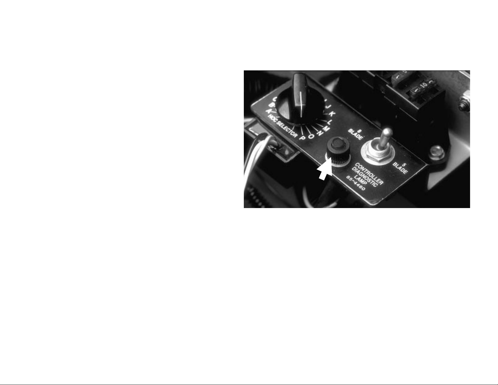
If the machine malfunctions, check the green Controller Diagnostic
Lamp. If the lamp is
electronic control unit (ECU) is functioning normally. If the lamp is
blinking, the controller has de tected a problem in the electrical cir cuit.
The lamp will stop blinking and automatically reset when the key
switch is turned OFF.
ON
, with ignition key switch in ON position, the
If Controller Diagnostic Lamp is
1. ECU has detected an output with a short circuit.
2. ECU has detected an output with an open circuit.
Use Diagnostic ACETM to find which output is malfunctioning.
NOTE: If the green Controller Diagnostic Lamp is blinking on and
off, connect the Diagnostic ACE, without turning the key switch off,
then toggle to “
Diagnostic ACE will indicate which output is faulty . T o stop the engine
without turning off the key switch , use the manua l fuel stop lever on
the injection pump or grasp the steering wheel, raise yo urself up off
the seat and lightly push the traction pedal so the interlock circuit
stops the engine.
If the controller diagnostic lamp is
1. ECU is not powered on.
2. Loop-back connector is not attached.
3. Diagnostic lamp is burned out.
4. ECU is not functioning correctly.
Check electrical connections, in put fuses and diagnostic lamp to find
malfunction. Make sure loop-back connector is secured to wire
harness connector.
OUTPUTS DISPLAYED”. The blinking LED on the
BLINKING ON
OFF
:
and
OFF
:
Controller Diagnostic Lamp
NOTE: Part number under CONTROLLER DIAGNOSTIC LAMP is the decal part
number; not the lamp. The lamp part number is 85-4491
Using the Diagnostic ACE (RM 5100-D/5300-D) Page 1
Page 4
1. Park machine on a level surface, engage parking brake, lower
cutting units and turn ignition key switch OFF.
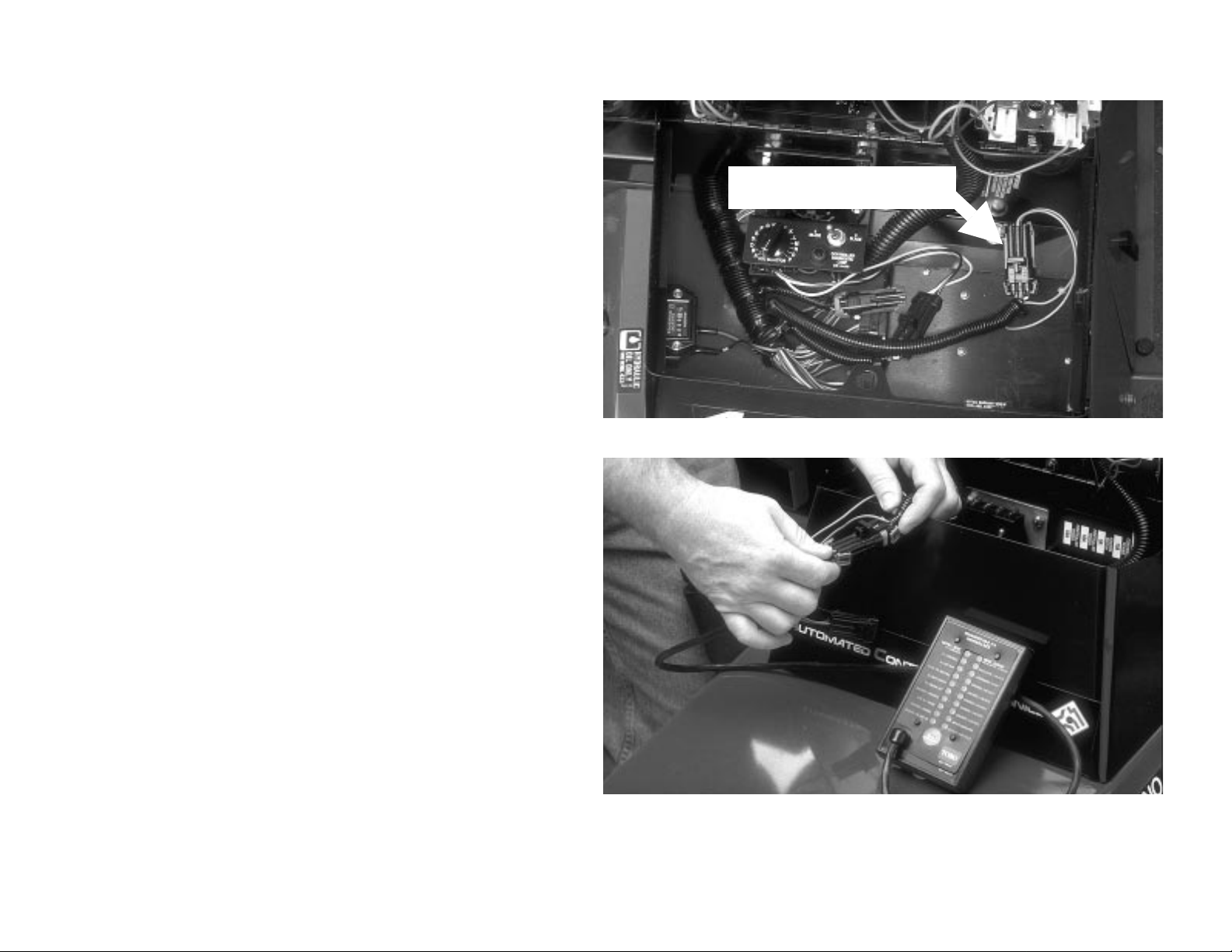
2. Carefully disconnect loop-back connector from wire harness.
3. Connect Diagnostic ACE to connector on wiring harness (where
loop-back connector was removed).
Disconnect loop-back connector
and connect Diagnostic ACE Display
TM
Installing Diagnostic ACE
Using the Diagnostic ACE (RM 5100-D/5300-D) Page 2
Page 5
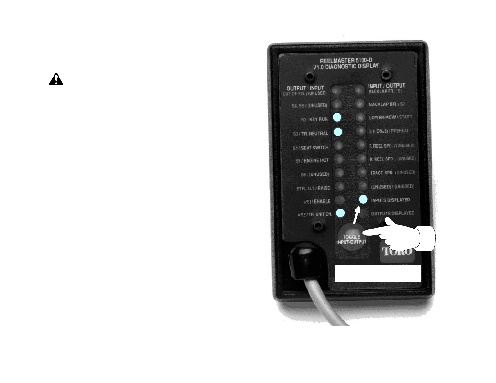
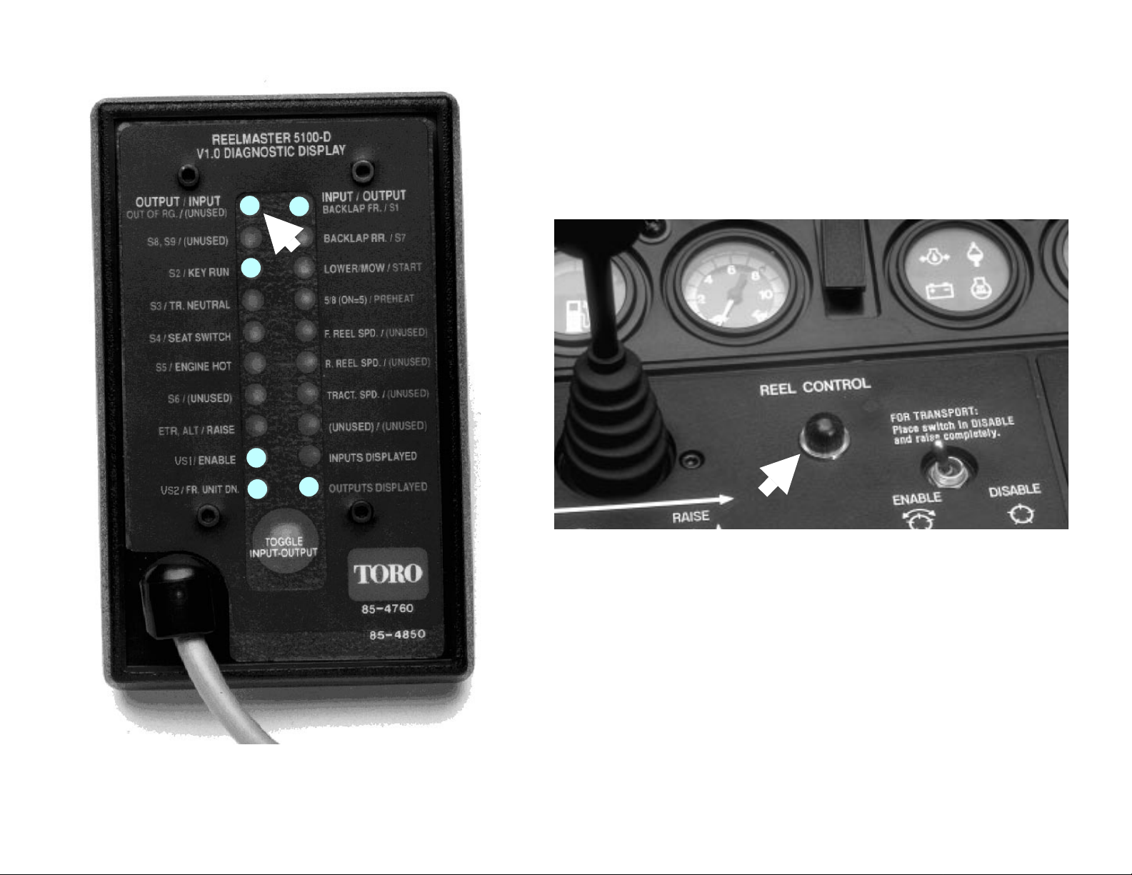
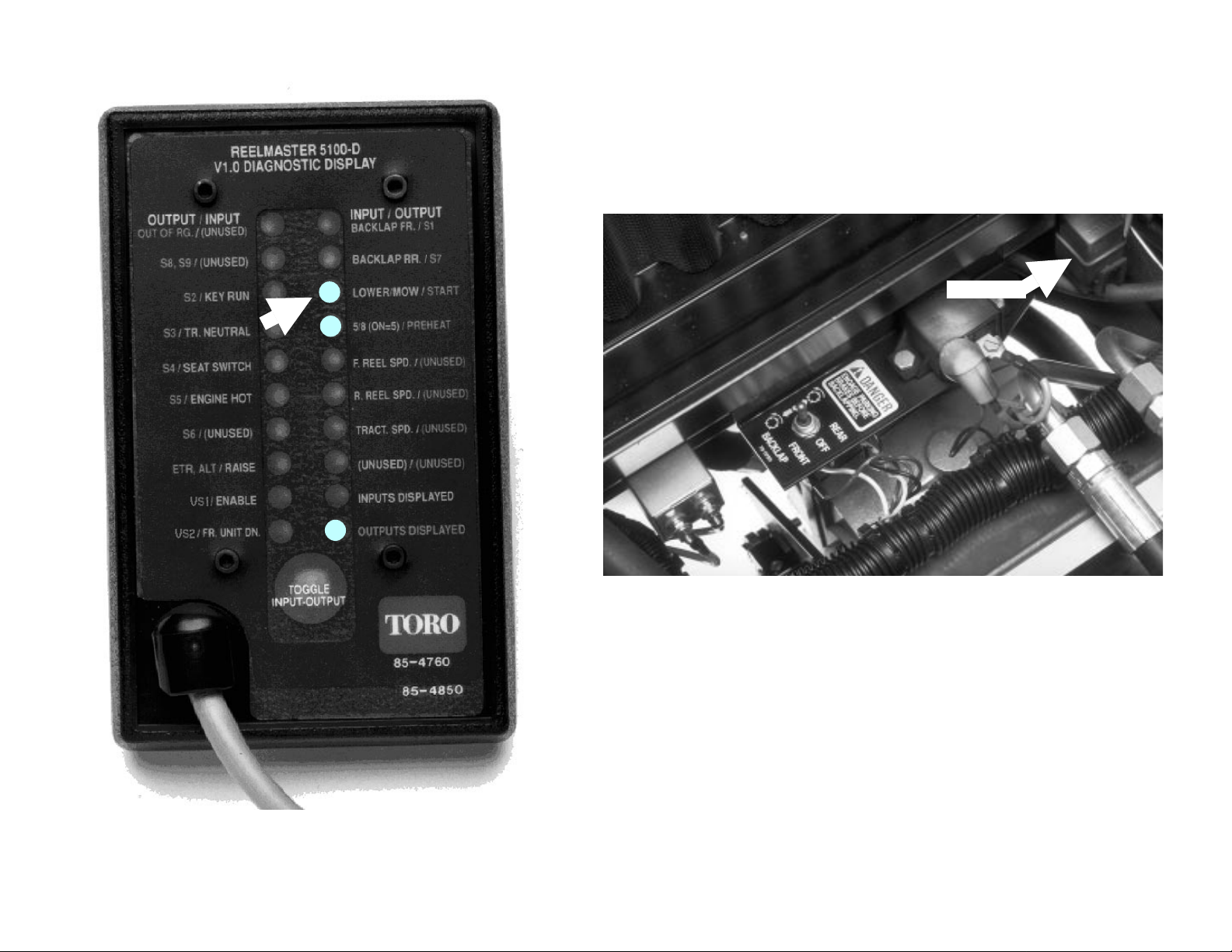
1. After connecting Diagn ostic ACE and turning key switch ON, move
Push INPUT-OUTPUT TOGGLE
so INPUTS DISPLAYED light is ON.
any input switch, such as the Enable/Disable switch, to get the
Diagnostic ACE display to function. DO NOT start t he eng ine.
CAUTION: To prevent possible personal injury, lower
cutting units before working on machine. If ignition key
switch is on, cutting units will lower when joystick is moved to
lower/mow position.
NOTE: After doing step 1, the “
This indicates that the ECU and Diagnostic ACE are operating
properly. If the green Controller Diagnostic Lamp on the machine
comes on, but the “INPUTS DISPLAYED” LED does not come on, there
is a problem with the Diagno stic ACE.
2. If necessary, push input-output toggle button so “INPUTS
DISPLAYED
NOTE: Red text on overlay decal refers to input switches and green
text to outputs.
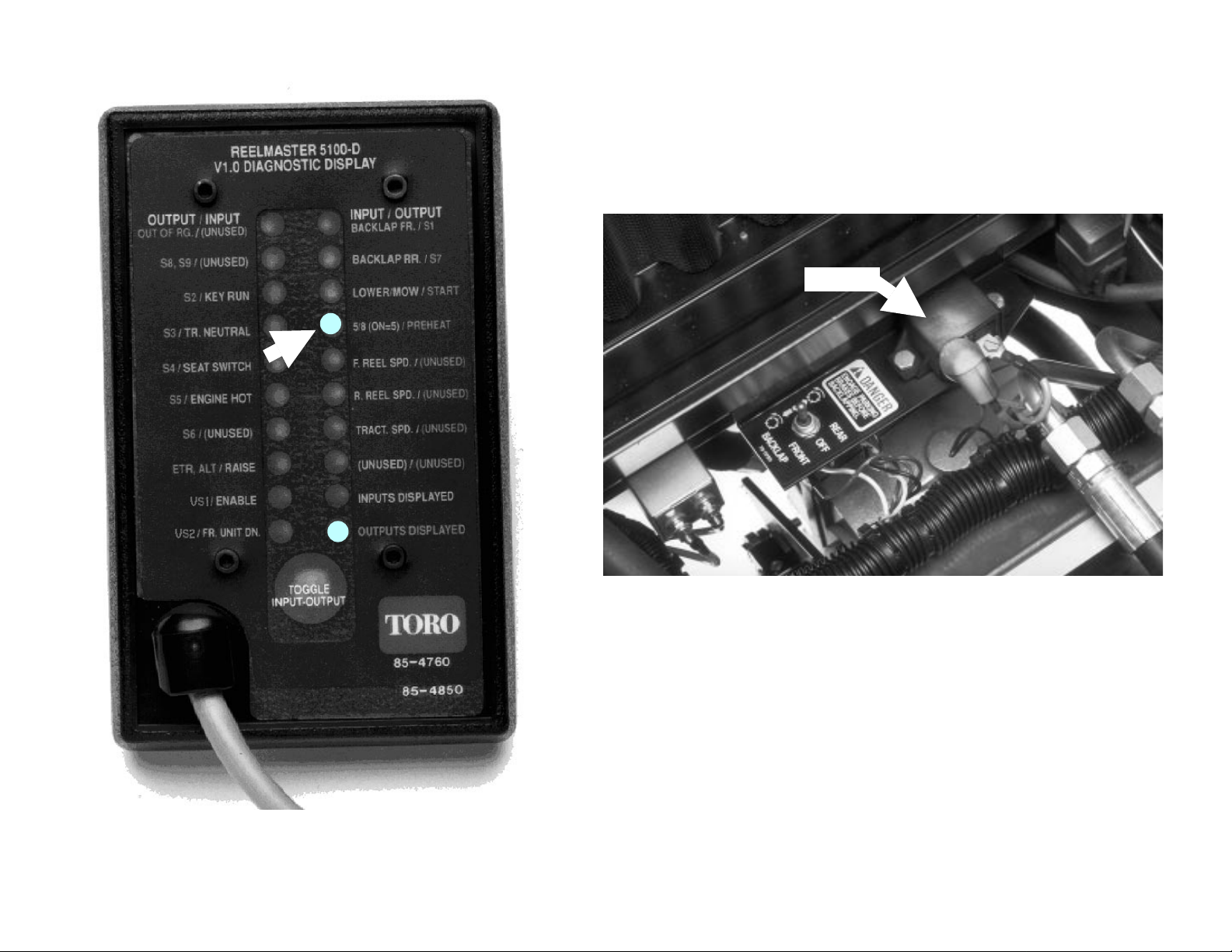
3. The Diagnostic ACE will illuminate the LED associated with each
input when that input switch is closed. Check each switch (input) by
opening and closing the switch, then verifying tha t the corresponding
LED goes on and off as the switch position is changed. For example,
with traction pedal in neutral, “TR. NEUTRAL” LED should be on, then
go off, when traction pedal is moved out of neutral. Check function
for each switch that can be changed manually.
4. If a switch is closed and corresponding LED does not go on, check
all wiring and connections to switch and/or test switch with a
continuity tester or ohm-meter. Replace any faulty switches and
repair or replace any faulty wiring or connectors.
” LED is on. Do not hold the b utton down.
INPUTS DISPLAYED” LED will be on.
Checking INPUTS
Using the Diagnostic ACE (RM 5100-D/5300-D) Page 3
Page 6
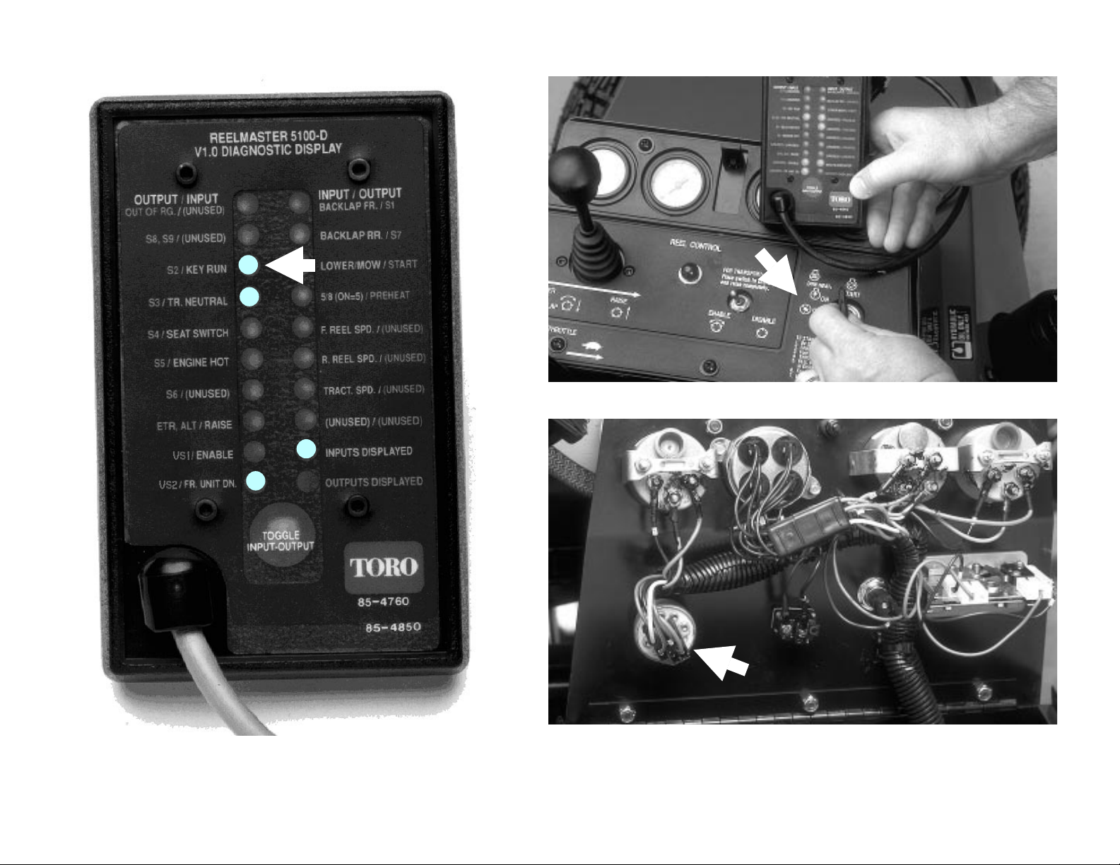
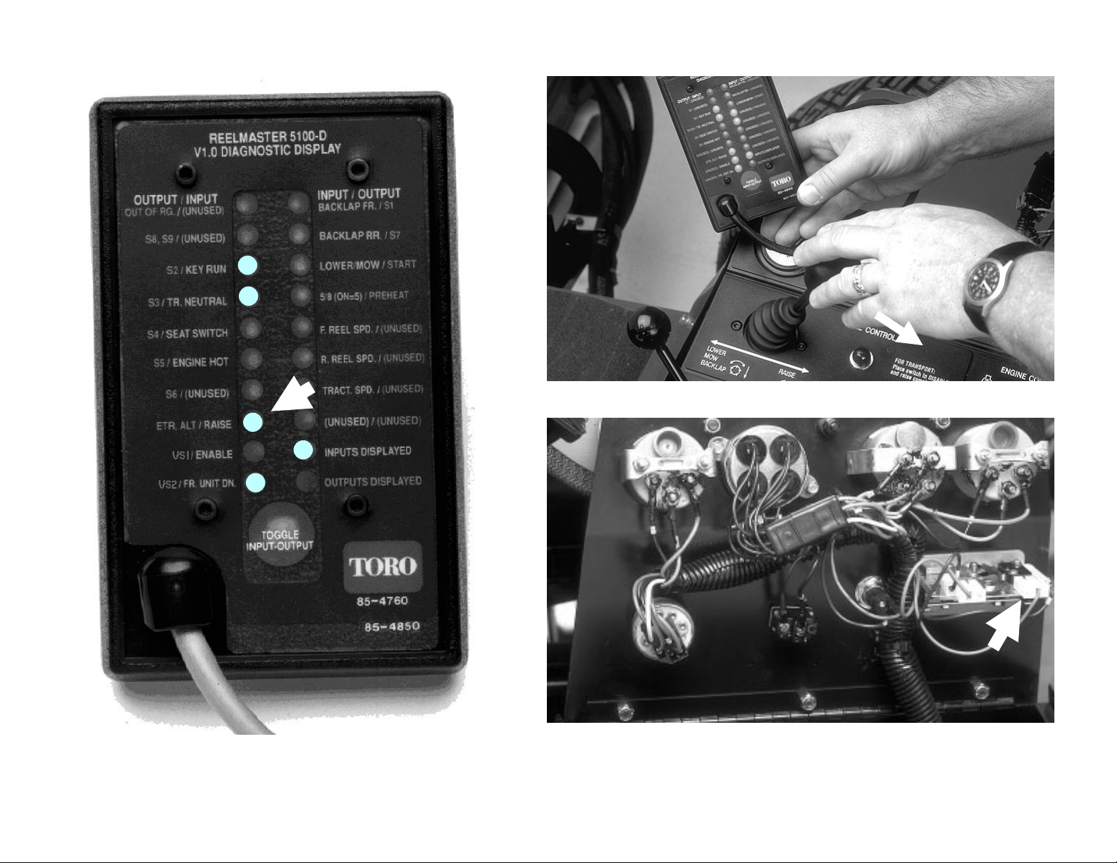
INPUT – KEY RUN
Using the Diagnostic ACE (RM 5100-D/5300-D) Page 4
Page 7
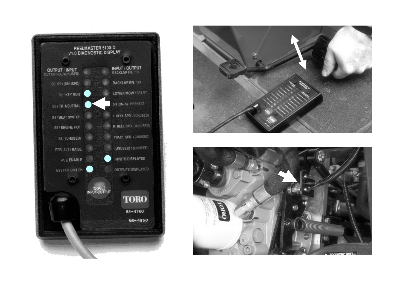
INPUT – TR. NEUTRAL
Using the Diagnostic ACE (RM 5100-D/5300-D) Page 5
Page 8
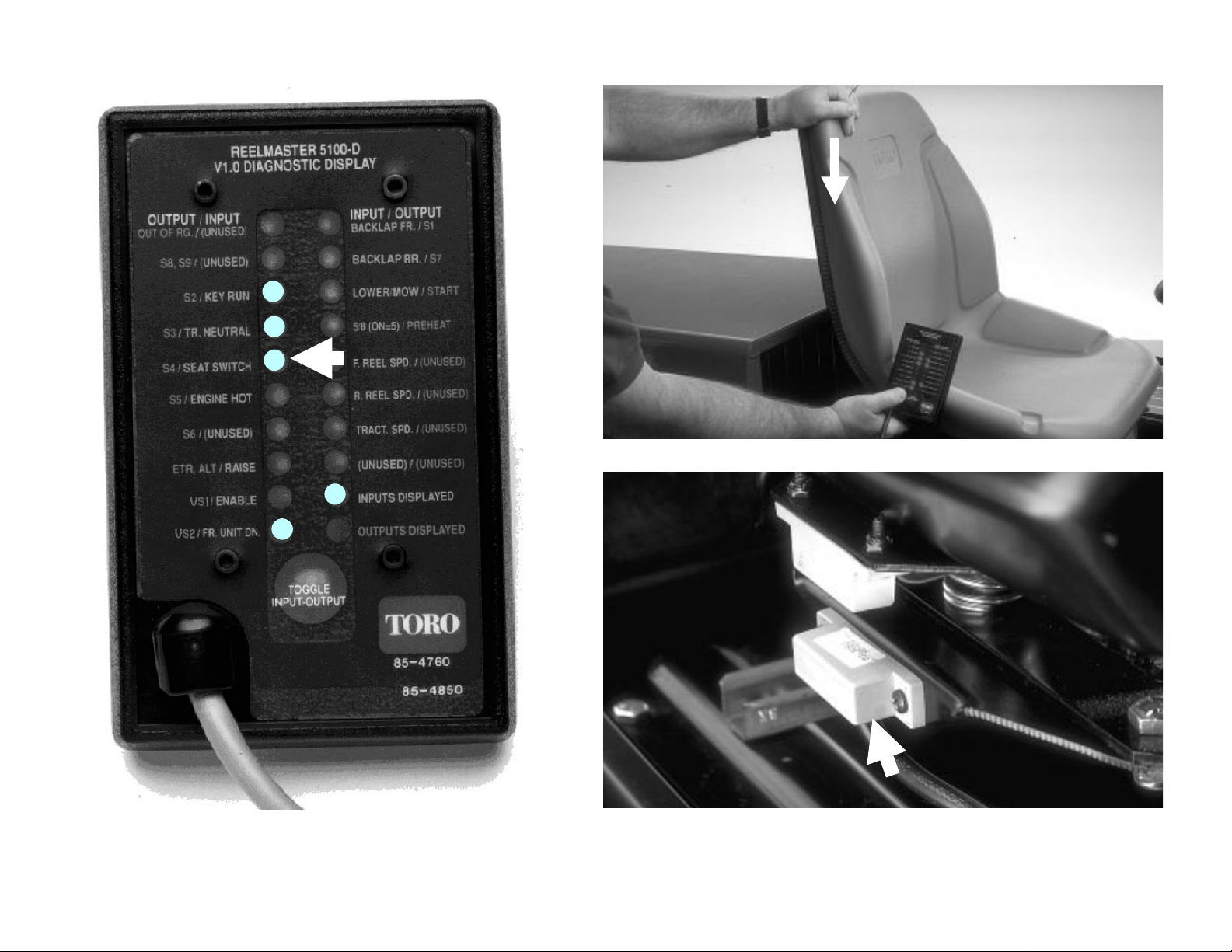
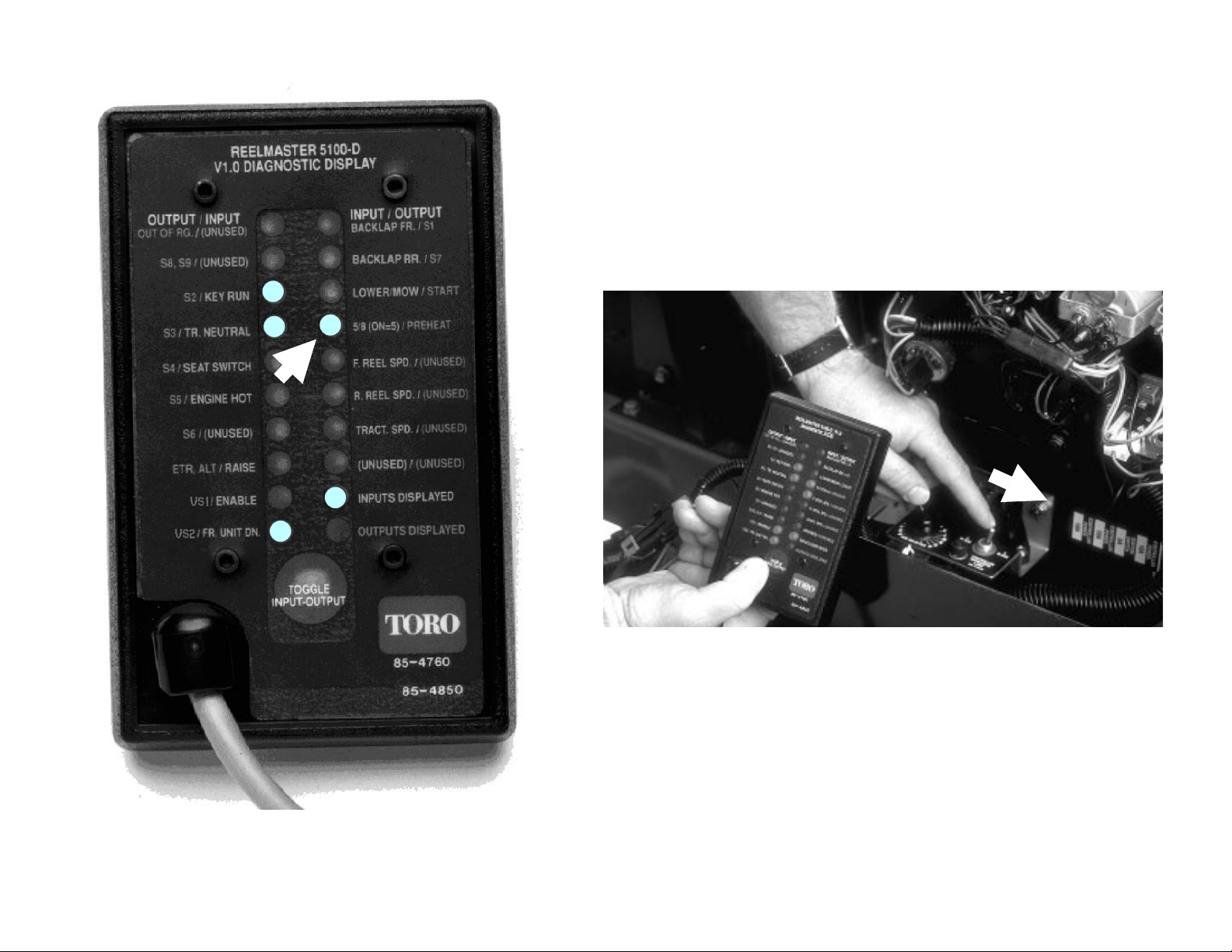
INPUT – SEAT SWITCH
Using the Diagnostic ACE (RM 5100-D/5300-D) Page 6
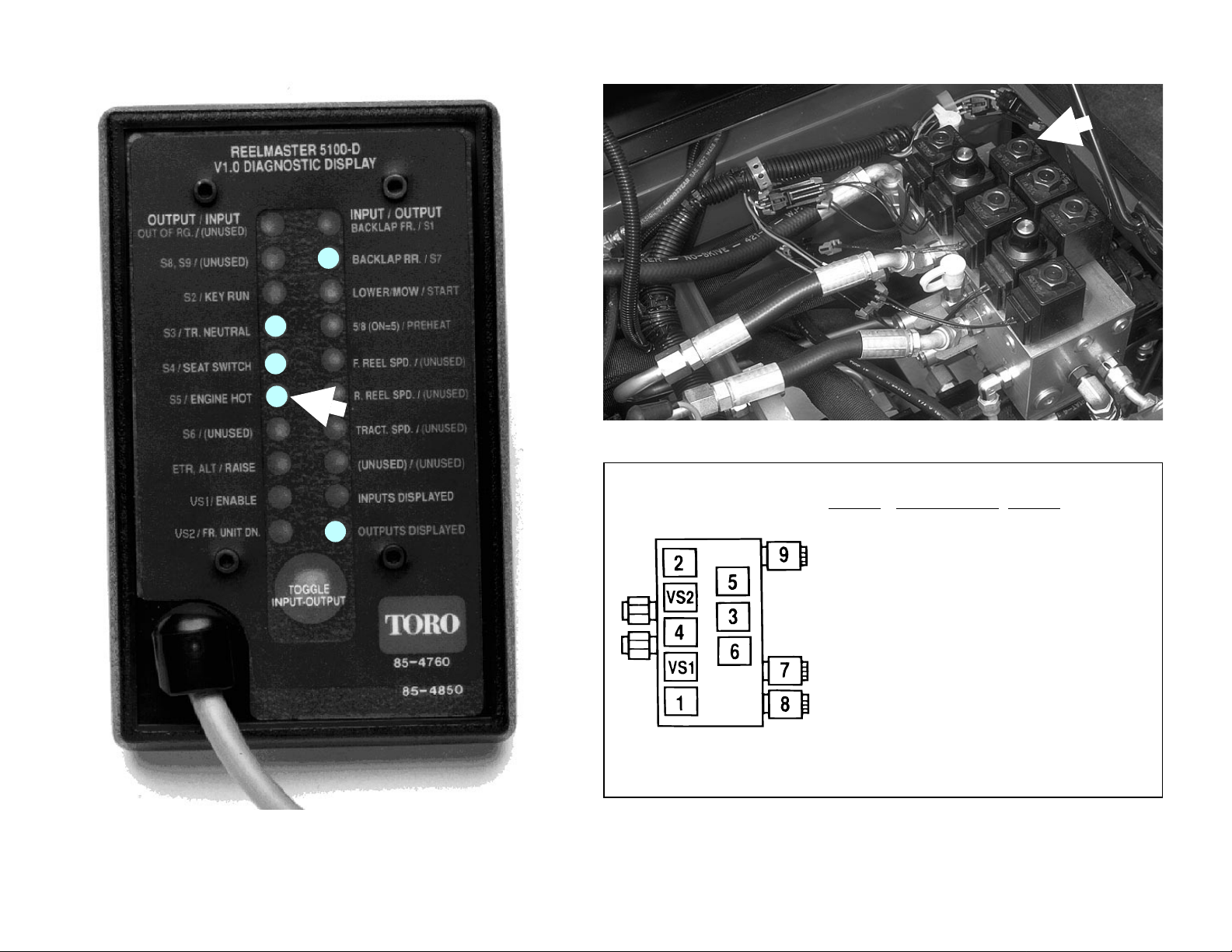
Page 9
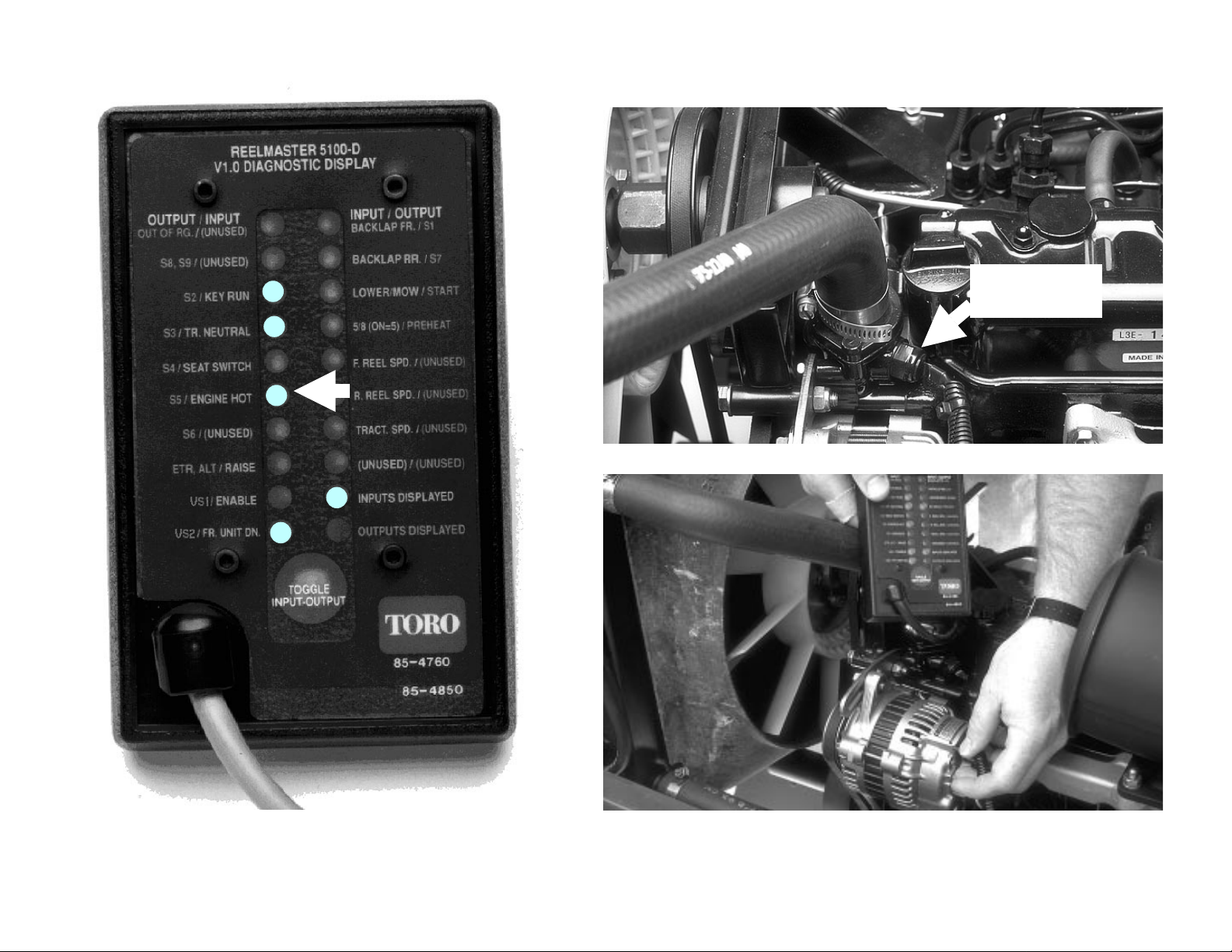
To test, disconnect
and ground terminal
to engine block.
INPUT – ENGINE HOT
Using the Diagnostic ACE (RM 5100-D/5300-D) Page 7
Page 10
INPUT – RAISE
Using the Diagnostic ACE (RM 5100-D/5300-D) Page 8
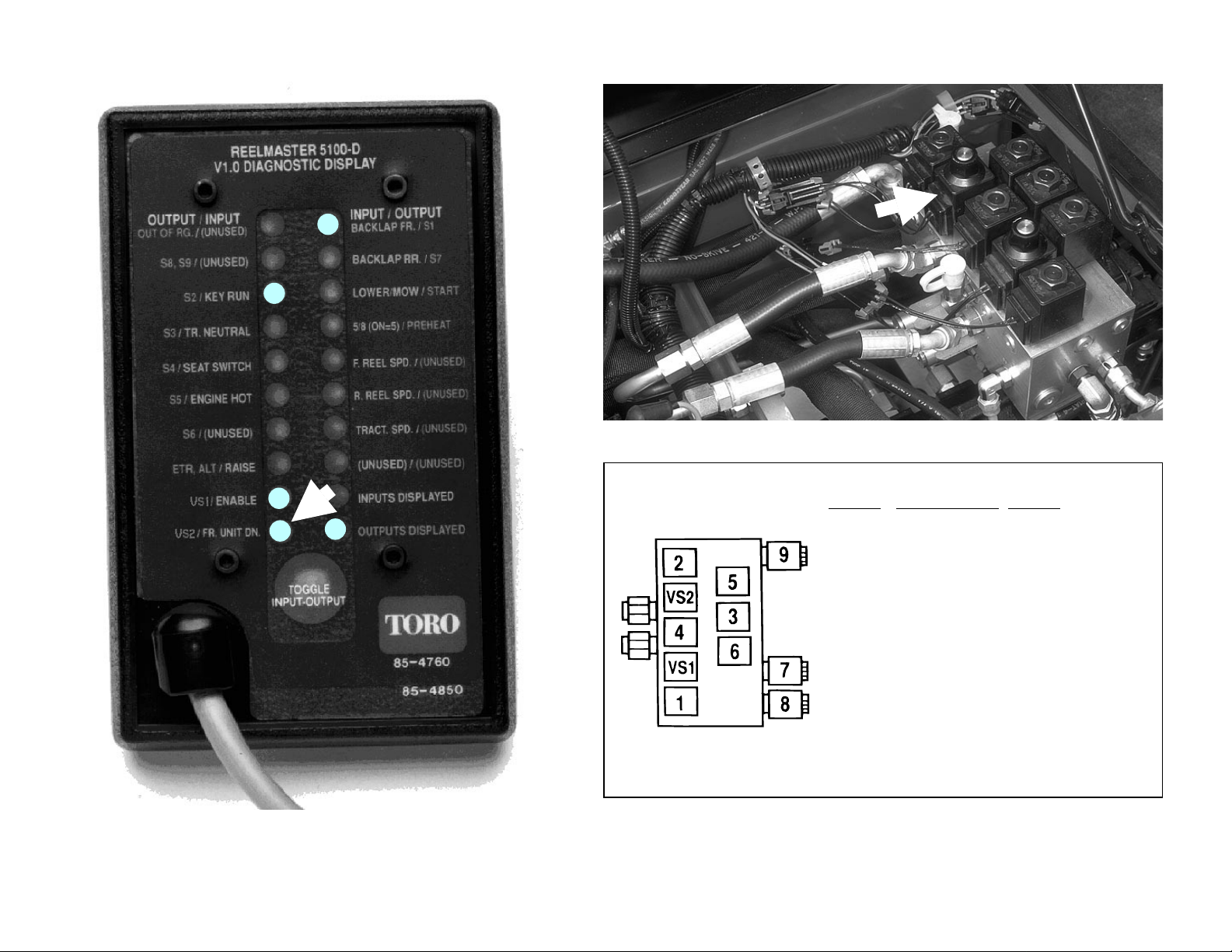
Page 11
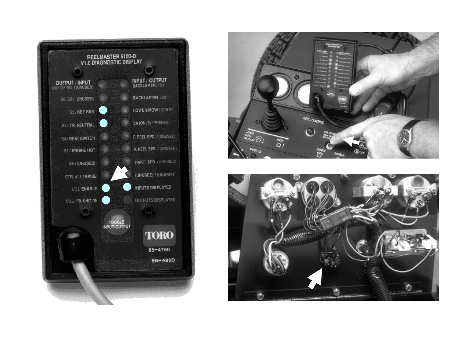
INPUT – ENABLE
Using the Diagnostic ACE (RM 5100-D/5300-D) Page 9
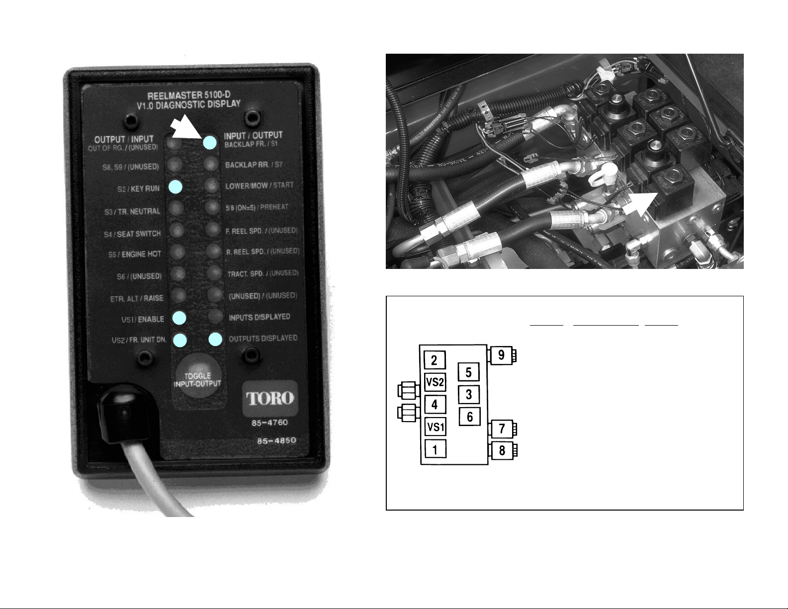
Page 12
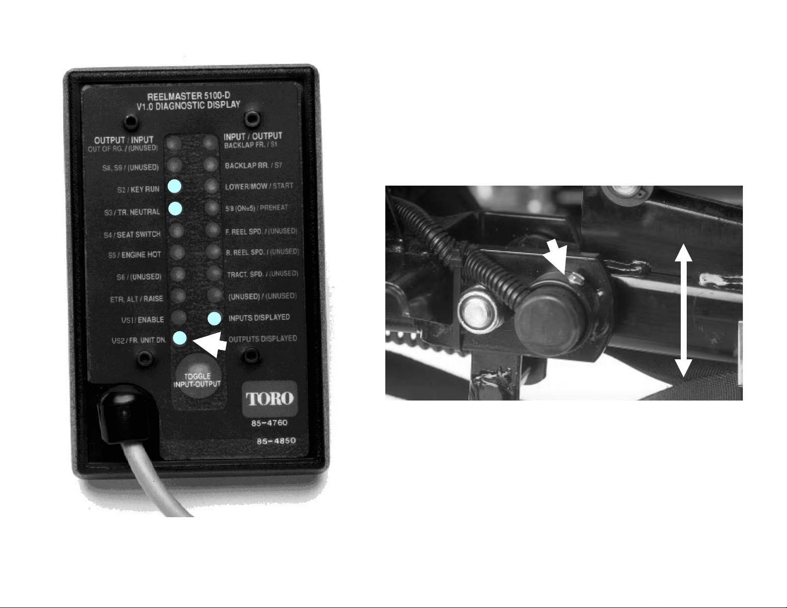
INPUT – FR. UNIT DN.
Using the Diagnostic ACE (RM 5100-D/5300-D) Page 10
Page 13

INPUT – BACKLAP FR.
Using the Diagnostic ACE (RM 5100-D/5300-D) Page 11
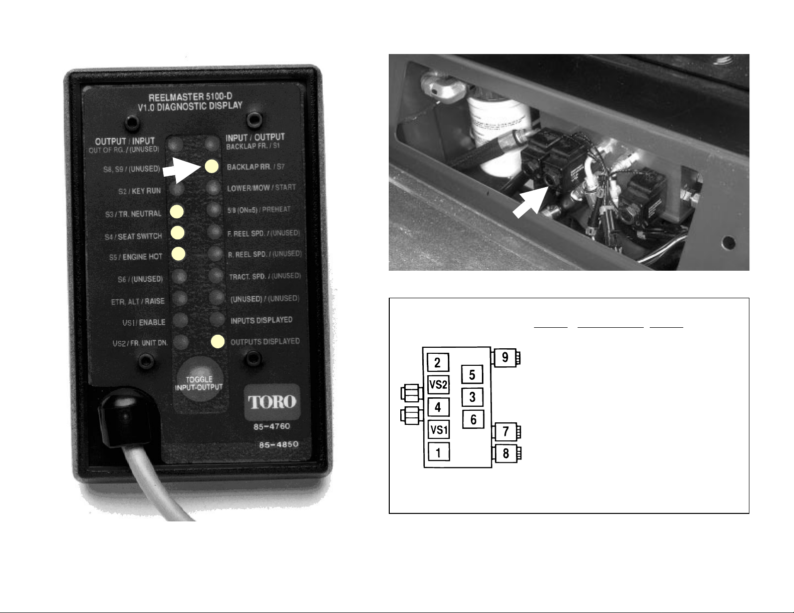
Page 14

INPUT – BACKLAP RR.
Using the Diagnostic ACE (RM 5100-D/5300-D) Page 12
Page 15

INPUT – LOWER/MOW
Using the Diagnostic ACE (RM 5100-D/5300-D) Page 13
Page 16
INPUT – 5/8 (ON = 5)
Using the Diagnostic ACE (RM 5100-D/5300-D) Page 14
Page 17
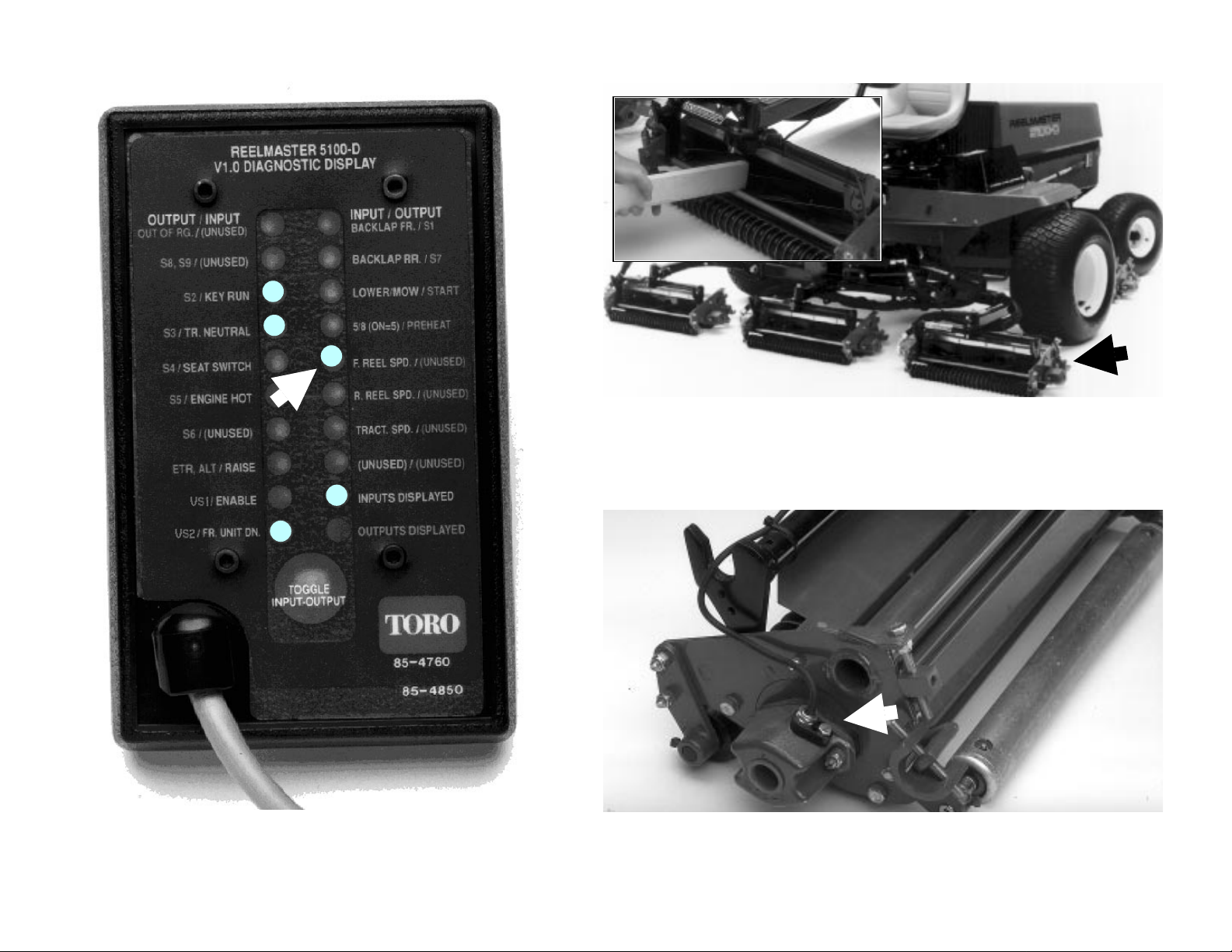
Use a piece of wood to manually turn the reel.
INPUT – F. REEL SPD.
Using the Diagnostic ACE (RM 5100-D/5300-D) Page 15
Page 18

Use a piece of wood to manually turn the reel.
INPUT – R. REEL SPD.
Using the Diagnostic ACE (RM 5100-D/5300-D) Page 16
Page 19
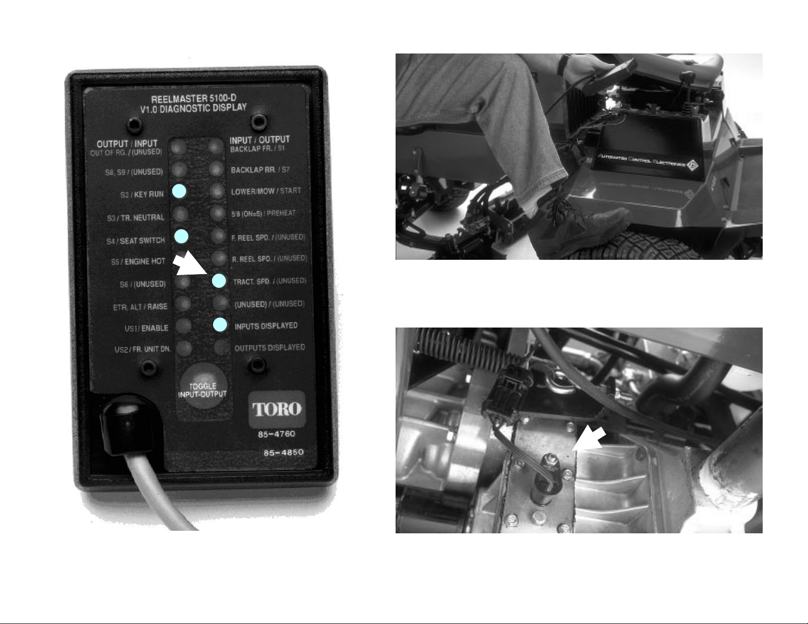
Release parking brake and move machine a small
distance (1 to 2 inches).
INPUT – TRAC. SPD
Using the Diagnostic ACE (RM 5100-D/5300-D) Page 17
Page 20
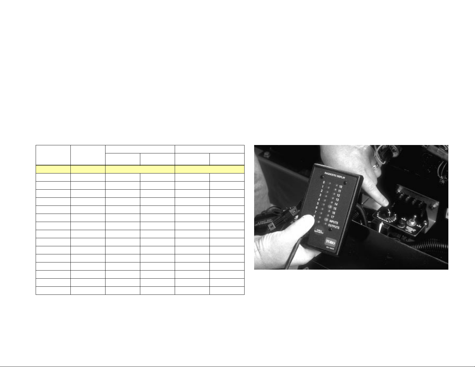
1. Remove overlay decal from front of Diagnostic ACE so numbers “0” to “17”
next to LED’s are visible.
2. Set ECU to special diagnostic mode:
A. Turn ignition key switch
B. Raise seat and set Backlap switch to
C. Set Enable/Disable switch to
D. Hold Lower/Mow-Raise lever in
to
ON position. Release Lower/Mow-Raise lever.
OFF.
FRONT backlap position.
DISABLE position.
RAISE position and turn ignition key switch
3. Slowly turn HOC Selector. LED’s on Diagnostic ACE will show how ECU is
enterpreting HOC Selector . LED labeled “0“ should be illu minate d whe n knob is
pointed to “A”, and LED labeled “15” sh ould be illuminate d when knob is pointe d
to “P”. T able below shows when machine is set for correct clip. It is not necessary
for knob to line up with letters on decal for machine to function normally.
Diagnostic
ACE Display
LED
0 A Full Speed Full Speed
1 B 0.25 6.4 0.50 12.7
2 C 0.30 7.6 0.55 14.0
3 D 0.35 8.9 0.60 15.2
4 E 0.40 10.2 0.65 16.5
5 F 0.45 11.4 0.70 17.8
6 G 0.50 12.7 0.75 19.1
7 H 0.55 14.0 0.80 20.3
8 I 0.60 15.2 0.85 21.6
9 J 0.65 16.5 0.90 22.8
10 K 0.70 17.8 0.95 24.0
11 L 0.75 19.0 1.00 25.4
12 M 0.80 20.3 1.10 27.0
13 N 0.85 21.6 1.20 30.0
14 O 0.90 22.9 1.30 33.0
15 P 0.95 24.1 1.40 36.0
HOC
Selector
Position
8 Blade Height-of-cut 5 Blade Height-of-cut
Inches mm Inches mm
4. Turn Ignition key switch OFF and in sta ll over la y decal on Dia gn ostic ACE.
INPUT – HOC Selector
Using the Diagnostic ACE (RM 5100-D/5300-D) Page 18
Page 21
1. After installing Diagnostic ACE, turn ignition key switch ON, but DO NOT start the
engine.
NOTE: After installing Diagnostic ACE and turning ignition key switch ON, the
INPUTS DISPLA YED” LED will be on. This indicates that the ECU and Diagnost ic ACE
“
are operating properly. If the green controller diagnostic lamp on the ma chine comes
on, but the “
Diagnostic ACE.
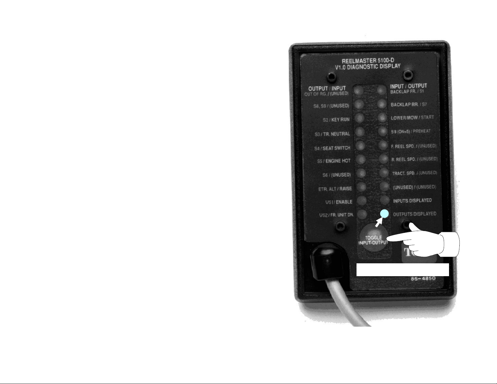
2. Push input-output toggle button so “OUTPUTS DISPLAYED” LED is on.
INPUTS DISPLAYED” LED does not come on, there is a problem with the
NOTE: It may be necessary to t ogg le betwe en “
DISPLAYED
button once. This may be done as often as necessary. DO NOT hold button.
NOTE: Red text on overlay decal refers to input switches and gr een text to outp uts.
3. Sit on the seat and attempt to operate desired function of mach ine – DO NOT start
the engine. The appropriate output LED’s sh ould illum inat e to in dicate that the ECU
is turning on that function.
If any output LED is
with that OUTPUT. To reset a flashing LED, turn the key switch OFF, then back ON.
If no output LED’s are flashing on and off, but the correct output LED’s do not
illuminate, verify that the required input switches are in the necessary positions to
allow that function to occur.
If input switches are correct, but output LED’s are not correct, this indicates a
controller malfunction.
If output LED’s are correct, but machine does not function properly, this indicates a
hydraulic problem.
NOTE: Due to electrical system constraint s, the output LED’s for “
and “
for one of those functions. If the machine problem appears to be with one of these
functions, see the troubleshooting charts in the Ree lmaster 5100-D Ser vice Manual.
” several times to do this proce dure. T o toggle back and forth, press toggle
FLASHING ON
ETR/ALT” may not flash on and off, even th ough an electrical proble m may exist
and
INPUTS DISPLAYED” and “OUTPUTS
OFF
, this indicates an electrical problem
ST ART”, “PREHEA T”
Push INPUT-OUTPUT TOGGLE
so OUTPUTS DISPLAYED light is ON.
Checking OUTPUTS
Using the Diagnostic ACE (RM 5100-D/5300-D) Page 19
Page 22
OUTPUT – OUT OF RG.
Using the Diagnostic ACE (RM 5100-D/5300-D) Page 20
Page 23
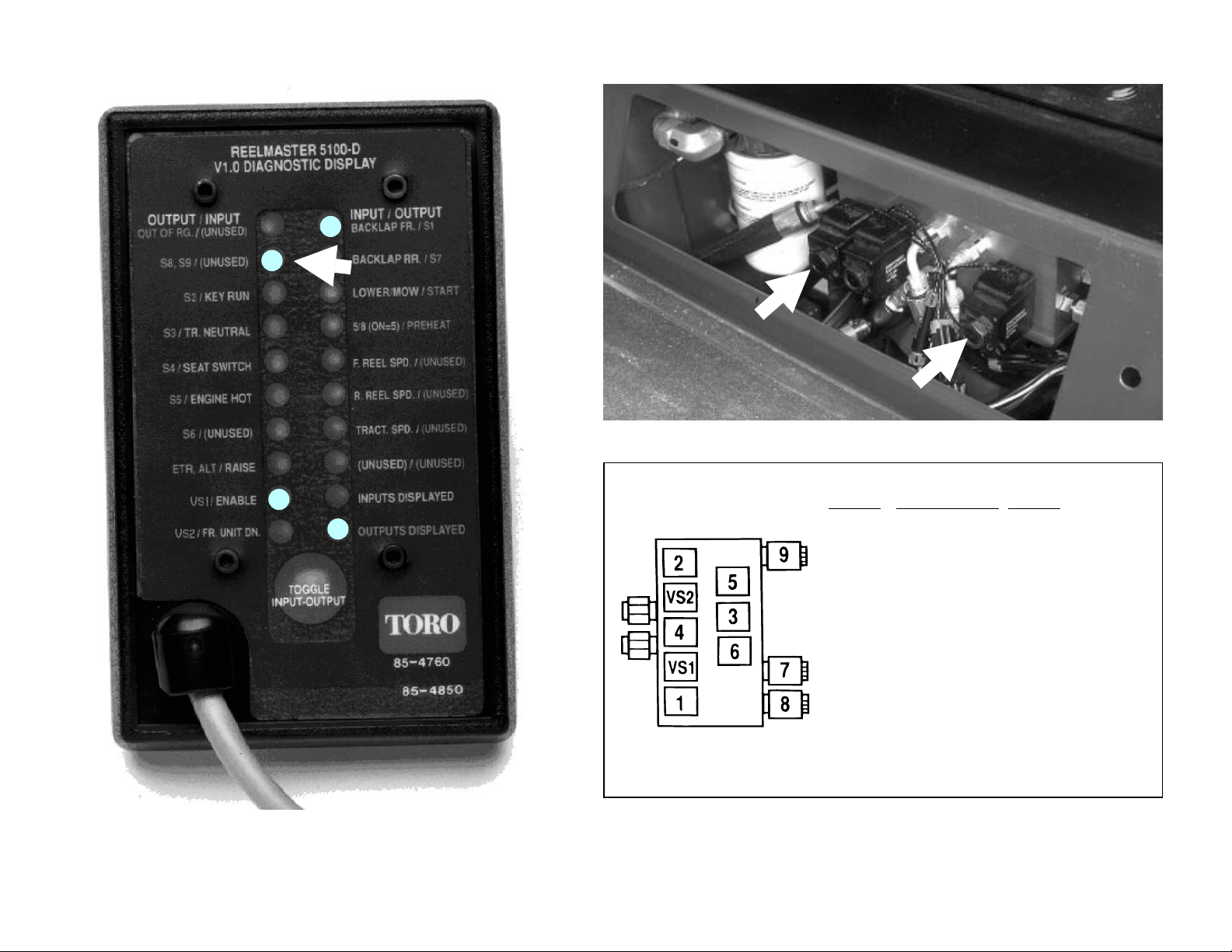
Solenoid Power Wire Color Function
VS1 Orange/Black Front reel speed
VS2 Orange/White Rear reel speed
S1 Pink/Blue Front reels On/Off
S2 Brown/White Rear reels On/Off
S3 Orange/Blue Lift / Lower front wing
S4 Yellow/Black Lift / Lower center
S5 Yellow/White Lift / Lower rear
S6 Orange/Red Lower any cutting unit
S7 Yellow/Blue Lift any cutting unit
S8 Black/Red Backlap
S9 Brown/White Backlap
cutting units
cutting unit
cutting units
OUTPUT – S8, S9
Using the Diagnostic ACE (RM 5100-D/5300-D) Page 21
Page 24
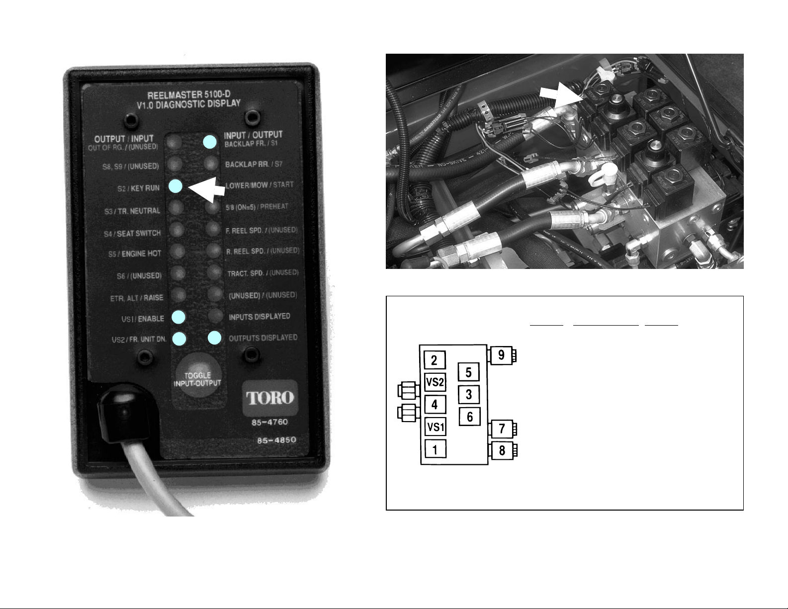
Solenoid Power Wire Color Function
VS1 Orange/Black Front reel speed
VS2 Orange/White Rear reel speed
S1 Pink/Blue Front reels On/Off
S2 Brown/White Rear reels On/Off
S3 Orange/Blue Lift / Lower front wing
S4 Yellow/Black Lift / Lower center
S5 Yellow/White Lift / Lower rear
S6 Orange/Red Lower any cutting unit
S7 Yellow/Blue Lift any cutting unit
S8 Black/Red Backlap
S9 Brown/White Backlap
cutting units
cutting unit
cutting units
OUTPUT – S2
Using the Diagnostic ACE (RM 5100-D/5300-D) Page 22
Page 25
Solenoid Power Wire Color Function
VS1 Orange/Black Front reel speed
VS2 Orange/White Rear reel speed
S1 Pink/Blue Front reels On/Off
S2 Brown/White Rear reels On/Off
S3 Orange/Blue Lift / Lower front wing
S4 Yellow/Black Lift / Lower center
S5 Yellow/White Lift / Lower rear
S6 Orange/Red Lower any cutting unit
S7 Yellow/Blue Lift any cutting unit
S8 Black/Red Backlap
S9 Brown/White Backlap
cutting units
cutting unit
cutting units
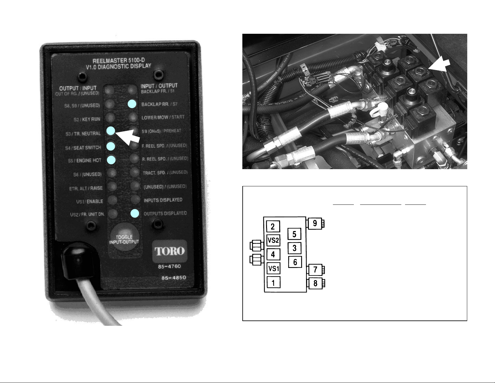
OUTPUT – S3
Using the Diagnostic ACE (RM 5100-D/5300-D) Page 23
Page 26

Solenoid Power Wire Color Function
VS1 Orange/Black Front reel speed
VS2 Orange/White Rear reel speed
S1 Pink/Blue Front reels On/Off
S2 Brown/White Rear reels On/Off
S3 Orange/Blue Lift / Lower front wing
S4 Yellow/Black Lift / Lower center
S5 Yellow/White Lift / Lower rear
S6 Orange/Red Lower any cutting unit
S7 Yellow/Blue Lift any cutting unit
S8 Black/Red Backlap
S9 Brown/White Backlap
cutting units
cutting unit
cutting units
OUTPUT – S4
Using the Diagnostic ACE (RM 5100-D/5300-D) Page 24
Page 27
Solenoid Power Wire Color Function
VS1 Orange/Black Front reel speed
VS2 Orange/White Rear reel speed
S1 Pink/Blue Front reels On/Off
S2 Brown/White Rear reels On/Off
S3 Orange/Blue Lift / Lower front wing
S4 Yellow/Black Lift / Lower center
S5 Yellow/White Lift / Lower rear
S6 Orange/Red Lower any cutting unit
S7 Yellow/Blue Lift any cutting unit
S8 Black/Red Backlap
S9 Brown/White Backlap
cutting units
cutting unit
cutting units
OUTPUT – S5
Using the Diagnostic ACE (RM 5100-D/5300-D) Page 25
Page 28

Solenoid Power Wire Color Function
VS1 Orange/Black Front reel speed
VS2 Orange/White Rear reel speed
S1 Pink/Blue Front reels On/Off
S2 Brown/White Rear reels On/Off
S3 Orange/Blue Lift / Lower front wing
S4 Yellow/Black Lift / Lower center
S5 Yellow/White Lift / Lower rear
S6 Orange/Red Lower any cutting unit
S7 Yellow/Blue Lift any cutting unit
S8 Black/Red Backlap
S9 Brown/White Backlap
cutting units
cutting unit
cutting units
OUTPUT – S6
Using the Diagnostic ACE (RM 5100-D/5300-D) Page 26
Page 29

ETR Solenoid
OUTPUT – ETR, ALT
Using the Diagnostic ACE (RM 5100-D/5300-D) Page 27
Page 30

Solenoid Power Wire Color Function
VS1 Orange/Black Front reel speed
VS2 Orange/White Rear reel speed
S1 Pink/Blue Front reels On/Off
S2 Brown/White Rear reels On/Off
S3 Orange/Blue Lift / Lower front wing
S4 Yellow/Black Lift / Lower center
S5 Yellow/White Lift / Lower rear
S6 Orange/Red Lower any cutting unit
S7 Yellow/Blue Lift any cutting unit
S8 Black/Red Backlap
S9 Brown/White Backlap
cutting units
cutting unit
cutting units
OUTPUT – VS1
Using the Diagnostic ACE (RM 5100-D/5300-D) Page 28
Page 31
Solenoid Power Wire Color Function
VS1 Orange/Black Front reel speed
VS2 Orange/White Rear reel speed
S1 Pink/Blue Front reels On/Off
S2 Brown/White Rear reels On/Off
S3 Orange/Blue Lift / Lower front wing
S4 Yellow/Black Lift / Lower center
S5 Yellow/White Lift / Lower rear
S6 Orange/Red Lower any cutting unit
S7 Yellow/Blue Lift any cutting unit
S8 Black/Red Backlap
S9 Brown/White Backlap
cutting units
cutting unit
cutting units
OUTPUT – VS2
Using the Diagnostic ACE (RM 5100-D/5300-D) Page 29
Page 32
Solenoid Power Wire Color Function
VS1 Orange/Black Front reel speed
VS2 Orange/White Rear reel speed
S1 Pink/Blue Front reels On/Off
S2 Brown/White Rear reels On/Off
S3 Orange/Blue Lift / Lower front wing
S4 Yellow/Black Lift / Lower center
S5 Yellow/White Lift / Lower rear
S6 Orange/Red Lower any cutting unit
S7 Yellow/Blue Lift any cutting unit
S8 Black/Red Backlap
S9 Brown/White Backlap
cutting units
cutting unit
cutting units
OUTPUT – S1
Using the Diagnostic ACE (RM 5100-D/5300-D) Page 30
Page 33
Solenoid Power Wire Color Function
VS1 Orange/Black Front reel speed
VS2 Orange/White Rear reel speed
S1 Pink/Blue Front reels On/Off
S2 Brown/White Rear reels On/Off
S3 Orange/Blue Lift / Lower front wing
S4 Yellow/Black Lift / Lower center
S5 Yellow/White Lift / Lower rear
S6 Orange/Red Lower any cutting unit
S7 Yellow/Blue Lift any cutting unit
S8 Black/Red Backlap
S9 Brown/White Backlap
cutting units
cutting unit
cutting units
OUTPUT – S7
Using the Diagnostic ACE (RM 5100-D/5300-D) Page 31
Page 34
Start relay
OUTPUT – START
Using the Diagnostic ACE (RM 5100-D/5300-D) Page 32
Page 35
OUTPUT – PREHEAT
Glow relay
Using the Diagnostic ACE (RM 5100-D/5300-D) Page 33
Page 36
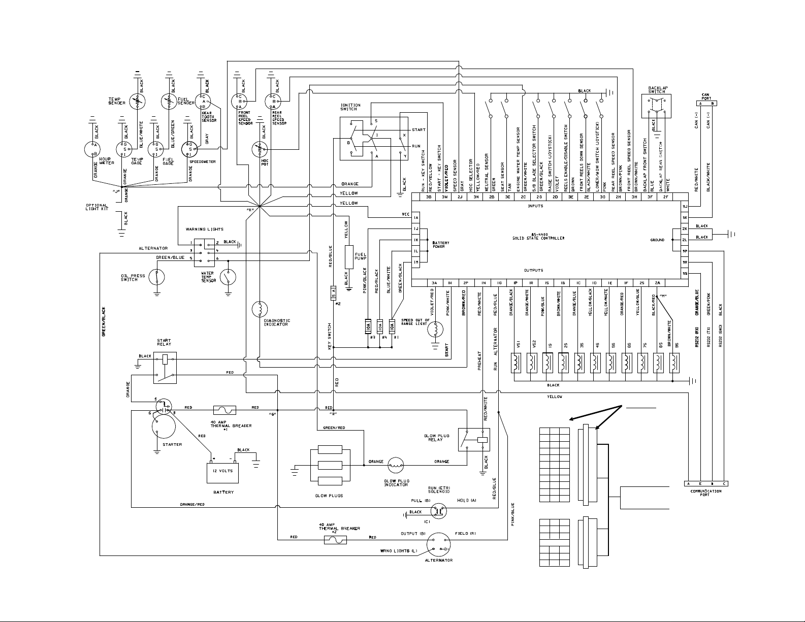
Electrical Schematic
EXAMPLE:
PIN NO'S.
213
213
A
B
C
D
E
F
G
H
I
J
K
A/L
B/M
C/N
D/P
E/R
F/S
See
Controller Diagram
– Violet/Red wire –
(Speed Out of Range Light)
HARNESS
3A on
Using the Diagnostic ACE (RM 5100-D/5300-D) Page 34
Page 37

NOTE: Schematic shown is in Lower/Mow mode.
Mow: S 1, VS1, S2, VS2 energized.
Lower: S6, S3, S4, S5 energized.
Hydraulic Schematic
Other modes:
Backlap Front: S1, VS1, S8, S9 energized.
Backlap Rear: S2, VS2, S8, S9 energized.
Lift all cutting units: S7, S3, S4, S5 energized.
Using the Diagnostic ACE (RM 5100-D/5300-D) Page 35
Page 38

Commercial Products
Form 92-800-SL, Rev. B
© The Toro Company – 1992, 1994
Printed in U.S.A.
 Loading...