

Page 1
ProForceDebrisBlower
FormNo.3377-579RevA
Groundsmaster
®
360TractionUnits
ModelNo.44547—SerialNo.313000001andUp
Registeratwww.T oro.com.
OriginalInstructions(EN)
*3377-579*A
Page 2
ThisproductcomplieswithallrelevantEuropeandirectives,
1
G021671
fordetailspleaseseetheseparateproductspecicDeclaration
ofConformity(DOC)sheet.
WARNING
CALIFORNIA
Proposition65Warning
Thisproductcontainsachemicalorchemicals
knowntotheStateofCaliforniatocausecancer,
birthdefects,orreproductiveharm.
Introduction
Thedebrisblowerismountedtoaride-onmachinewhich
isintendedtobeusedbyprofessional,hiredoperatorsin
commercialapplications.Itisprimarilydesignedtousewind
powertoquicklyclearlargeareasofunwanteddebrison
well-maintainedlawnsinparks,golfcourses,sportselds,
andoncommercialgrounds.
Readthisinformationcarefullytolearnhowtooperateand
maintainyourproductproperlyandtoavoidinjuryand
productdamage.Youareresponsibleforoperatingthe
productproperlyandsafely .
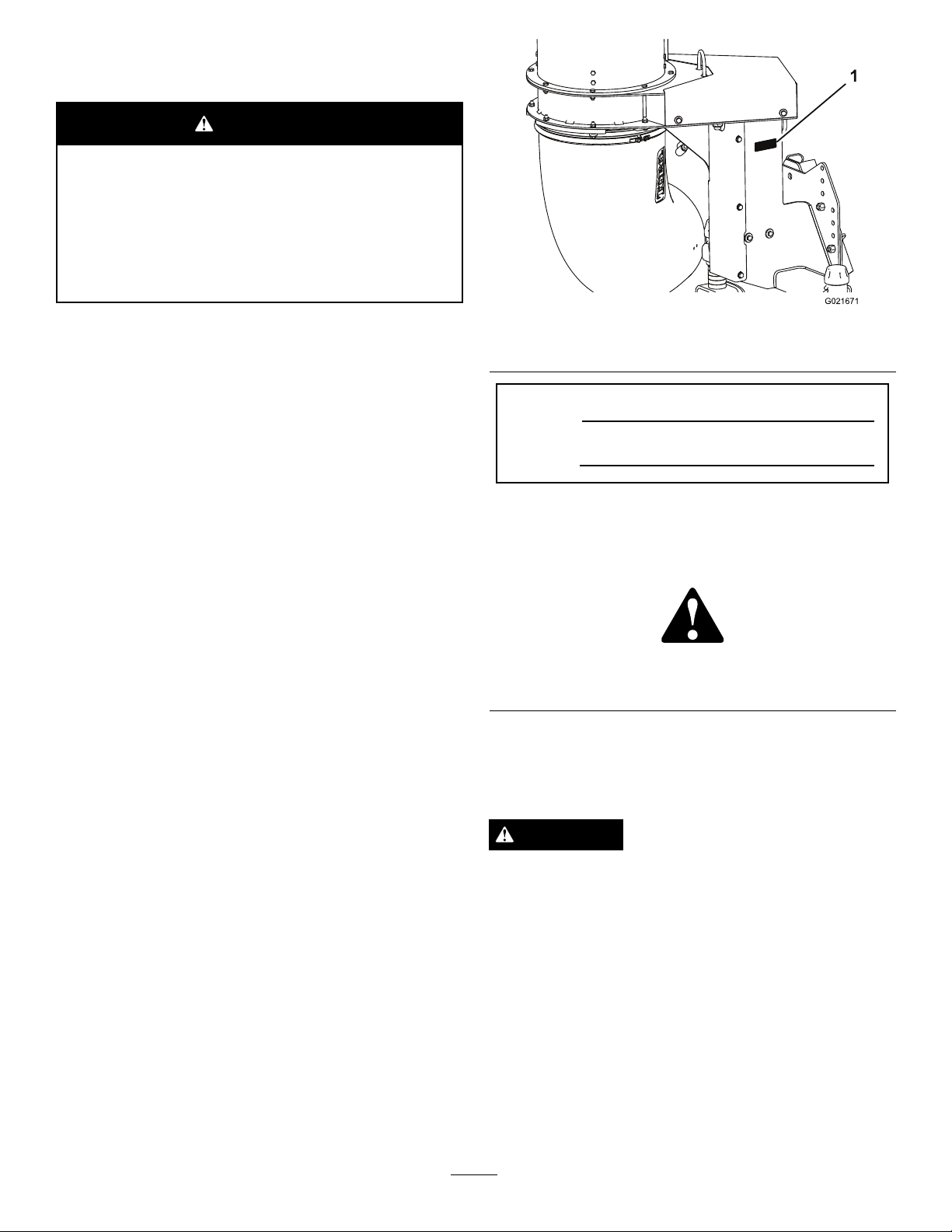
Figure1
1.Modelandserialnumberlocation
ModelNo.
SerialNo.
Thismanualidentiespotentialhazardsandhassafety
messagesidentiedbythesafetyalertsymbol(
Figure2),
whichsignalsahazardthatmaycauseseriousinjuryordeath
ifyoudonotfollowtherecommendedprecautions.
YoumaycontactTorodirectlyatwww .Toro.comforproduct
andaccessoryinformation,helpndingadealer,ortoregister
yourproduct.
Wheneveryouneedservice,genuineToroparts,oradditional
information,contactanAuthorizedServiceDealerorToro
CustomerServiceandhavethemodelandserialnumbersof
yourproductready .
Figure1identiesthelocationofthe
modelandserialnumbersontheproduct.Writethenumbers
inthespaceprovided.
Figure2
1.Safetyalertsymbol
Thismanualuses2otherwordstohighlightinformation.
Importantcallsattentiontospecialmechanicalinformation
andNoteemphasizesgeneralinformationworthyofspecial
attention.
CAUTION
Ifausermakeschangesormodicationsnot
expresslyapprovedbythepartyresponsiblefor
compliance,theycouldvoidtheuser'sauthorityto
operatetheequipment.
©2013—TheToro®Company
8111LyndaleAvenueSouth
Bloomington,MN55420
Contactusatwww.T oro.com.
2
PrintedintheUSA.
AllRightsReserved
Page 3

Contents
Safety
Introduction..................................................................2
Safety...........................................................................3
SafeOperatingPractices...........................................3
SafetyandInstructionalDecals.................................5
Setup............................................................................6
1RemovingtheBlowerfromtheCrate.......................7
2InstallingtheDriveShafttotheBlowerGear
BoxShaft............................................................8
3InstallingtheMountingPlatetotheDebris
BlowerFrame......................................................9
4MountingtheDebrisBlowertotheTraction
Unit...................................................................9
5InstallingtheProximitySwitch...............................10
6GreasingtheMachine...........................................11
ProductOverview.........................................................12
Controls...............................................................12
Specications........................................................12
Operation....................................................................13
ThinkSafetyFirst...................................................13
AdjustingtheBlowerNozzleHeight.........................14
OperatingTips.......................................................14
Maintenance.................................................................16
Lubrication............................................................16
CheckingtheGearBoxLubrication..........................16
CheckingtheNozzle...............................................17
AdjustingtheNozzleBelt........................................17
Storage..................................................................18
Hazardcontrolandaccidentpreventionaredependent
upontheawareness,concern,andpropertraining
ofthepersonnelinvolvedintheoperation,transport,
maintenance,andstorageofthemachine.Improper
useormaintenanceofthemachinecanresultininjury
ordeath.Toreducethepotentialforinjuryordeath,
complywiththefollowingsafetyinstructions.
SafeOperatingPractices
Training
•ReadtheOperator'sManualandothertrainingmaterial.
Iftheoperator(s)ormechanic(s)cannotreadEnglishitis
theowner'sresponsibilitytoexplainthismaterialtothem.
•Becomefamiliarwiththesafeoperationoftheequipment,
operatorcontrols,andsafetysigns.
•Alloperatorsandmechanicsshouldbetrained.The
ownerisresponsiblefortrainingtheusers.
•Neverletchildrenoruntrainedpeopleoperateorservice
theequipment.Localregulationsmayrestricttheageof
theoperator.
•Theowner/usercanpreventandisresponsiblefor
accidentsorinjuriesoccurringtohimselforherself,other
peopleorproperty.
Preparation
•Evaluatetheterraintodeterminewhataccessoriesand
attachmentsareneededtoproperlyandsafelyperform
thejob.Onlyuseaccessoriesandattachmentsapproved
bythemanufacturer.
•Wearappropriateclothingincludinghardhat,safety
glassesandhearingprotection.Longhair,looseclothing
orjewelrymaygettangledinmovingparts.
•Inspecttheareawheretheequipmentistobeusedand
removeallobjectssuchasrocks,toysandwirewhichcan
bethrownbythemachine.
•Keepallbystandersawayfromtheoperatingarea.
•Keepallshieldsandsafetydevicesinplace.Ifashield,
safetydevice,ordecalisillegibleordamaged,repairor
replaceitbeforeoperationiscommenced.Alsotighten
anyloosenuts,bolts,andscrewstoensurethatthe
machineisinsafeoperatingcondition.
•Checkthatsafetyswitchesandshieldsareattachedand
functioningproperly.Donotoperateunlesstheyare
functioningproperly.
Operation
•Neveroperatethedebrisblowerwhenitisnotconnected
toatowvehicle.
•Bealert,slowdownandusecautionwhenmakingturns.
Lookbehindandtothesidebeforechangingdirections.
3
Page 4

•Beawareoftheblowernozzledirectionanddonotpoint
itatanyone.
•Useextremecarewhenloadingorunloadingthemachine
intooroffofatrailerortruck.
•Usecarewhenapproachingblindcorners,shrubs,trees,
orotherobjectsthatmayobscurevision.
•Donotruntheengineinordirecttheblowernozzleinto
aconnedareawithoutadequateventilation.Exhaust
fumesarehazardousandcouldpossiblybedeadly.
•Usingthemachinedemandsattention.Topreventloss
ofcontrol:
–Operateonlyindaylightorwhenthereisgood
articiallight.
–Driveslowlyandwatchforholesorotherhidden
hazards.
–Donotdriveclosetoasandtrap,ditch,creek,or
otherhazard.
–Reduceyourspeedwhenmakingsharpturnsand
whenturningonhillsides.
–Avoidsuddenstartsandstops.
•Performonlythosemaintenanceinstructionsdescribedin
thismanual.Ifmajorrepairsareeverneededorassistance
isdesired,contactanAuthorizedToroDistributor.
•Toreduceapotentialrehazard,keeptheenginefreeof
excessivegrease,grass,leaves,andaccumulationsofdirt.
Neverwashawarmengineoranyelectricalpartswith
water.
•Besurethatthemachineisinsafeoperatingconditionby
keepingnuts,bolts,andscrewstight.Checkthefanshaft
bearingmountingboltsandnutsfrequentlytobesure
thattheyaretightenedtospecication.
•Iftheenginemustberunningtoperformamaintenance
adjustment,keephands,feet,clothing,andotherpartsof
thebodyawayfromthefanandothermovingparts.
•Keephandsandfeetawayfrommovingparts.Ifpossible,
donotmakeadjustmentswiththeenginerunning.
•Keepallpartsingoodworkingconditionandallhardware
tightened.Replaceallwornordamageddecals.
•UseonlyT oroapprovedattachments.Warrantymaybe
voidedifusedwithunapprovedattachments.
–Beforebackingup,looktotherearandensurethat
nooneisbehindthemachine.
–Watchoutfortrafcwhennearorcrossingroads.
Alwaysyieldtheright-of-way .
•Stayawayfromthenozzleopeningwhenthemachine
isoperating.Keepallbystandersawayfromthenozzle
openinganddon’tdirectdischargetowardbystanders.
•Donotoperatethemachineundertheinuenceof
alcoholordrugs.
•Lightningcancausesevereinjuryordeath.Iflightning
isseenorthunderisheardinthearea,donotoperate
themachine;seekshelter.
•Ifthetowvehicleenginestallsorthemachineloses
headwayandcannotmakeittothetopofaslope,donot
turnthemachinearound.Alwaysbackthetowvehicle
slowlystraightdowntheslope.
•Donottakeaninjuryrisk!Whenapersonorpet
appearsunexpectedlyinorneartheoperatingarea,stop
operation.Carelessoperation,combinedwithterrain
angles,ricochets,orimproperlypositionedguardscan
leadtothrownobjectinjuries.Donotresumeoperation
untiltheareaiscleared.
MaintenanceandStorage
•Parkmachineonlevelground.Neverallowuntrained
personneltoservicemachine.
•Usejackstandstosupportcomponentswhenrequired.
•Removethekeyfromtheignitionswitchtoprevent
accidentalstartingoftheenginewhenservicing,adjusting,
orstoringthemachine.
4
Page 5
SafetyandInstructionalDecals
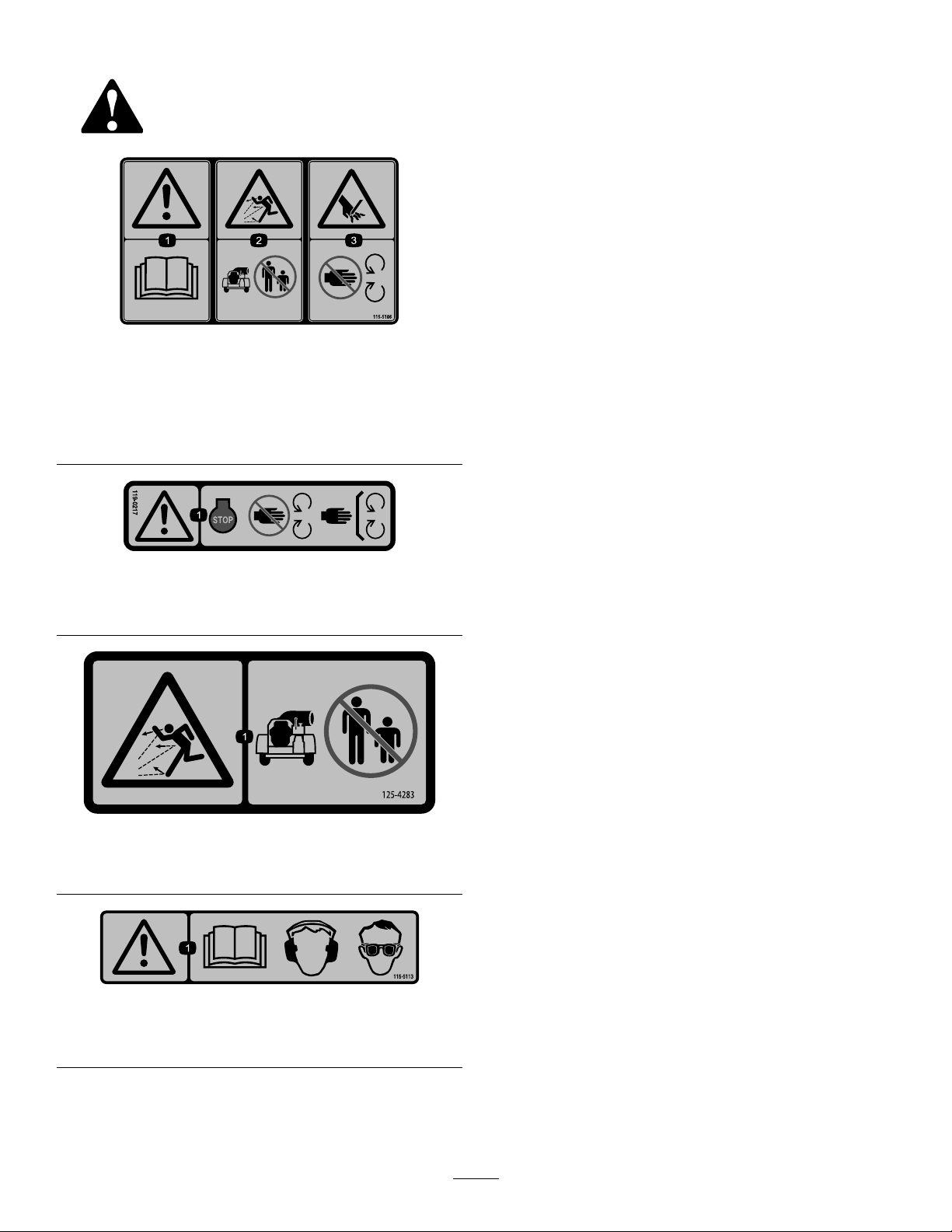
Safetydecalsandinstructionsareeasilyvisibletotheoperatorandarelocatednearanyareaofpotential
danger.Replaceanydecalthatisdamagedorlost.
115-5106
1.Warning—readtheOperator'sManual.
2.Thrownobjecthazard—keepbystandersasafedistance
fromthemachine.
3.Cutting/dismembermenthazard;hand—stayawayfrom
movingparts;keepallguardsandshieldsinplace.
119–0217
1.Warning—stoptheengine;keepawayfrommovingparts;
keepallguardsandshieldsinplace.
125–4283
1.Thrownobjecthazard—keepbystandersawayfromthe
machine.
115-5113
1.Warning—readtheOperator'sManual,wearhearingand
eyeprotection.
5
Page 6
Setup
LooseParts
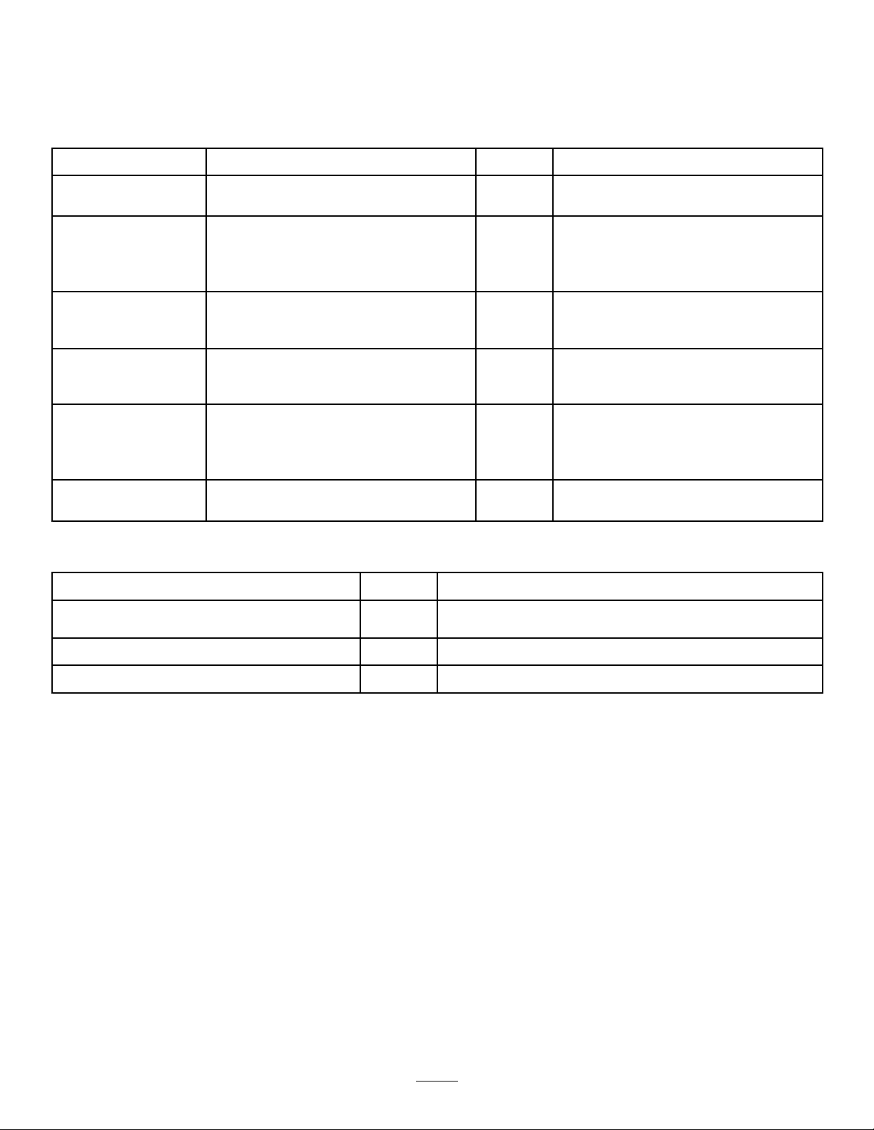
Usethechartbelowtoverifythatallpartshavebeenshipped.
ProcedureDescription
1
2
3
4
5
6
MediaandAdditionalParts
Qty.
Nopartsrequired
Driveshaftassembly
Rollpin1
Bolt,5/16x1-3/4inch
Locknut,5/16inch
Mountingplate1
Bolt,1/2x1-1/4inches
Locknut,1/2inch
Debrisblowerassembly1
Lockingpin1
Hairpincotter1
Proximityswitchassembly1
Sensorplate
Carriagescrew,5/16x1–1/4inch
Flangenut,5/16inch
GeneralPurposeLithiumBaseGreaseA/RGreasethemachine
–
1
2
2
4
4
1
2
2
Removetheblowerfromthecrate
Installthedriveshafttotheblowergear
boxshaft
Installthemountingplatetothedebris
blowerframe
Mounttheblowertothetractionunit
Installtheproximityswitch
Use
Description
PartsCatalog
Operator'sManual
OperatorTrainingMaterial
CerticateofCompliance
Note:Determinetheleftandrightsidesofthemachine
fromthenormaloperatingposition.
Note:Toinstallandoperatethedebrisblower,thetraction
unitmustbea4WheelDrivemachinewhichisequipped
withtheFrontQuickAttachFrontFrame,Model30509and
oneofthefollowing;theElectricAccessoryKit,partno.
115–0019ortheJoystickKit,model31219.
Qty.
Use
1
1
1
1
Readbeforeoperating.
Viewbeforeoperatingthemachine
EnsureCEcompliance.
6
Page 7
1
1
2
3
4
G021672
1
2
G02 1674
1
2
RemovingtheBlowerfromthe Crate
NoPartsRequired
Procedure
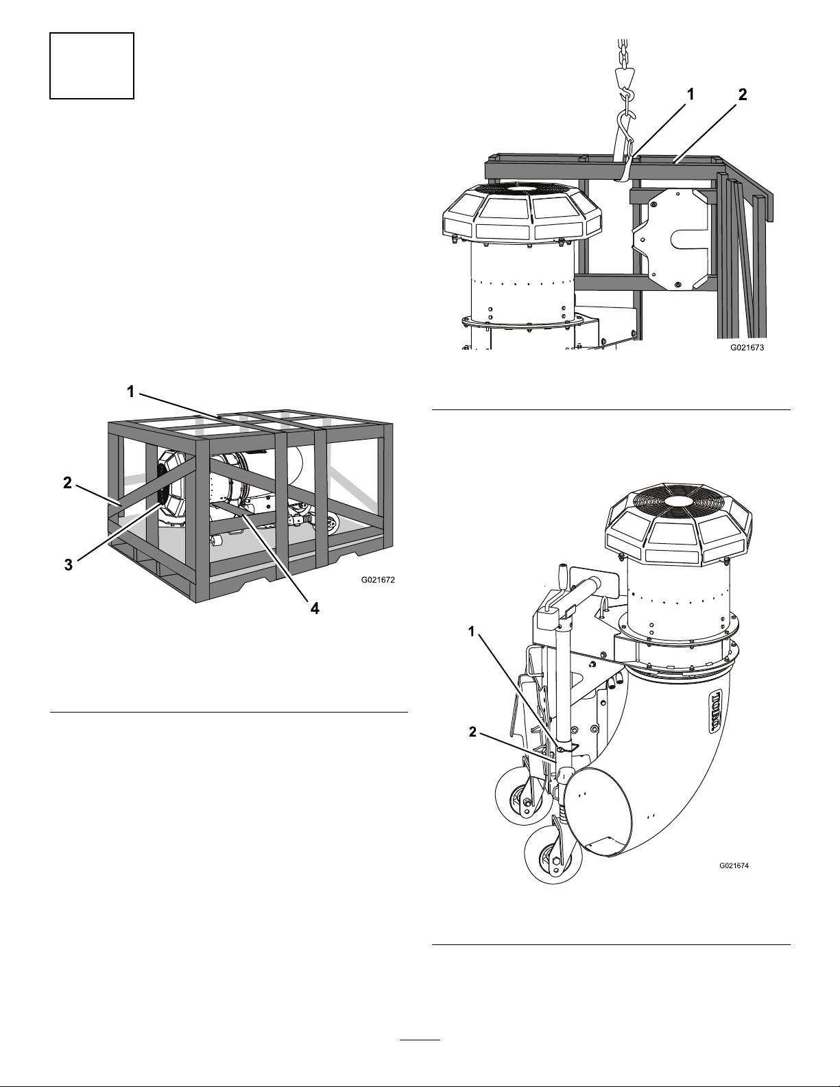
UsetheinstructionsinProcedure1tosimplifytheremoval
oftheblowerfromthecrate.
Important:Beforetheblowerframeisunboltedfrom
theshippingcrateorthecrateisremoved,makesureto
installthejackstandtohelpstabilizetheblower.
1.Removethetopofthecrate(Figure3).
Figure4
1.Liftstrap
5.Removethesnapperpinsecuringthejackstandtubeto
thestoragetube(Figure5).Removethejackassembly
fromthestorageposition.
2.Topend,2x4,deckboard
Figure3
1.Topofcrate3.Topofmachine
2.Endofcrate
2.Removetheendofthecratewhichistowardthetop
ofthemachine(Figure3).
3.Removetheboardthatisundertheblowerhousing
(Figure3).
4.Secureastraptothetopend,2x4,deckboardand
liftthepalletuntilthecrateandblowerisstandingup
vertically(Figure4).
4.Boardunderblower
housing
Figure5
1.Snapperpin
2.Jackstandtube
6.Removethestrapfromthepalletandattachittothe
liftloopontheblower(Figure6).Liftthebloweruntil
thestrapistight.
7
Page 8
G021675
1
Figure6
G021676
1
G021637
1
2
3
1.Liftloop
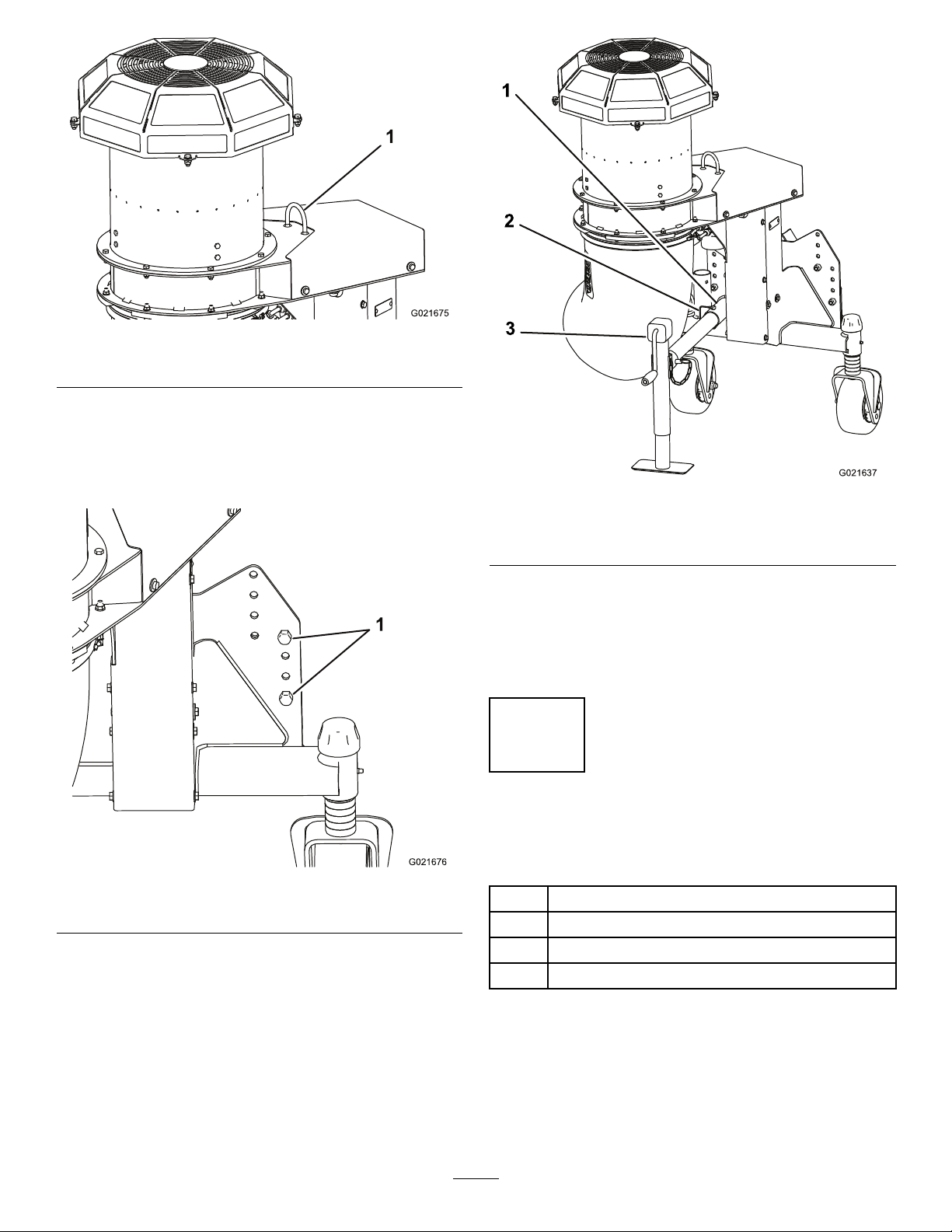
7.Carefullyremovethescrewsholdingtheblowertothe
woodpallet.Afterthescrewsareremoved,slidethe
crateawayfromtheblowerandlowerthebloweruntil
thecastorwheelstouchtheoorbutthestrapisstill
tight(Figure7).
Figure8
1.Frametube3.Jackstand
2.Snapperpin
9.Removethecabletiesecuringthecrankhandletothe
jackcrank.
10.Crankthejackstanddownuntilthejackpadislevel
withthecastorwheeltires.
11.Removethestrapfromtheblowerliftloop.
2
InstallingtheDriveShafttothe BlowerGearBoxShaft
Figure7
1.Screws
8.Insertthejackstandtubeintotheframetube,align
theholesandsecureitintopositionwiththesnapper
pin(
Figure8).
Partsneededforthisprocedure:
1
Driveshaftassembly
1Rollpin
2
Bolt,5/16x1-3/4inch
2
Locknut,5/16inch
Procedure
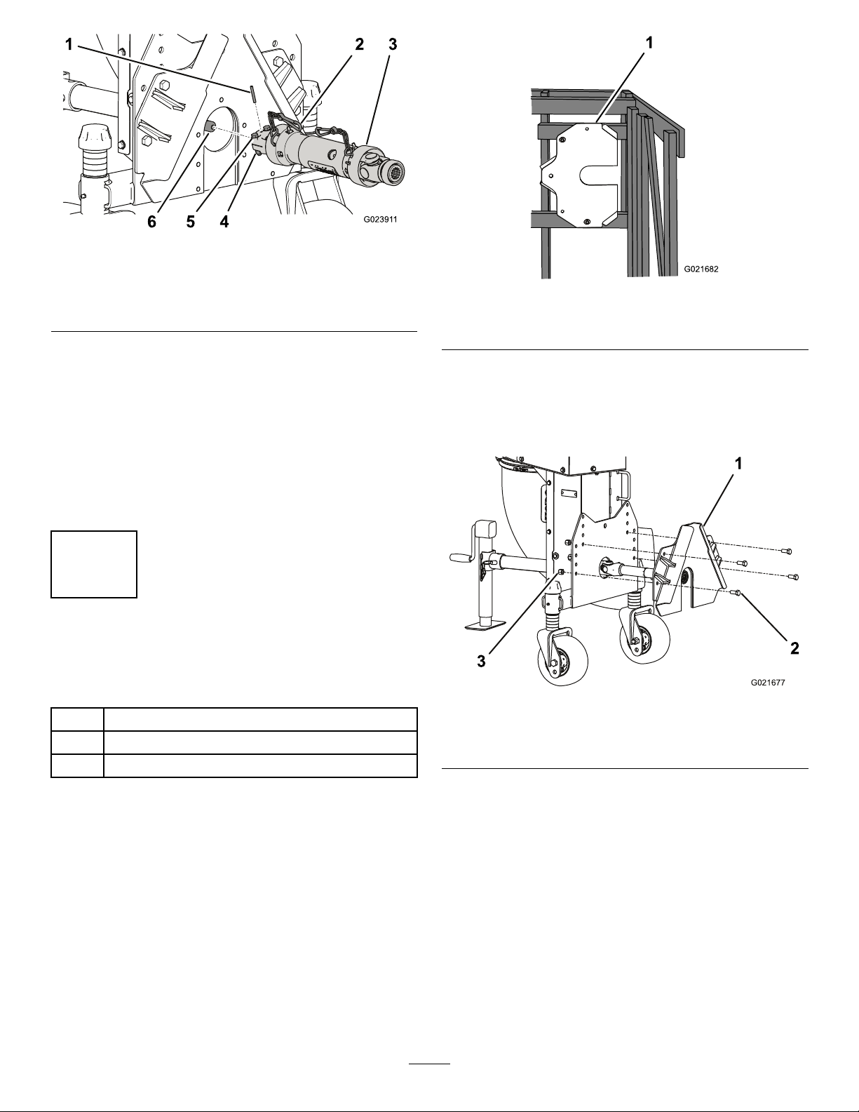
1.Removethecabletiesecuringthedriveshafttothe
shippingcrate.
2.Slidethedriveshaftontothegearboxshaft.Alignthe
mountingholesinthegearboxshaftwiththeholesin
thedriveshaftandslidethemtogether.
8
Page 9
6
1
5 4
3
G02391 1
2
Figure9
G021682
1
G021677
1
2
3
1.Rollpin
2.Safetychain(2)5.Locknuts,5/16inch
3.Driveshaft6.Gearboxshaft
3.Securethemwitharollpin(Figure9).
4.Securethedriveshafttothegearboxshaftwithtwo
5/16x1–3/4inchboltsand5/16inchlocknuts
(Figure9).
5.Torquetheboltsandlocknutsto18to25N-m(175
to225in-lb).
6.Removethecabletiekeepingthedriveshafttogether
7.Securethesafetychaintoblowerframe(Figure9).
4.Bolts,5/16x1–3/4inch
3
InstallingtheMountingPlate totheDebrisBlowerFrame
Figure10
1.Mountingplate
2.Installthemountingplatetothedebrisblowerframe
with(4)1/2x1-1/4inchboltsand(4)1/2inch
locknuts(Figure11).Usethelowersetofholeson
eachsideofthemountingplatewheninstalling.T orque
theboltsto92to113N-m(68to82ft-lb)
Partsneededforthisprocedure:
1Mountingplate
4
Bolt,1/2x1-1/4inches
4
Locknut,1/2inch
1.Mountingplate
2.Bolt(4)
Figure11
3.Locknut(4)
Procedure
1.Removetheboltssecuringthemountingplatetothe
crate(
Figure10).
9
Page 10
4
1
2
G023910
1
2
G021678
MountingtheDebrisBlowerto
theTractionUnit
Partsneededforthisprocedure:
1Debrisblowerassembly
1Lockingpin
1Hairpincotter
Procedure
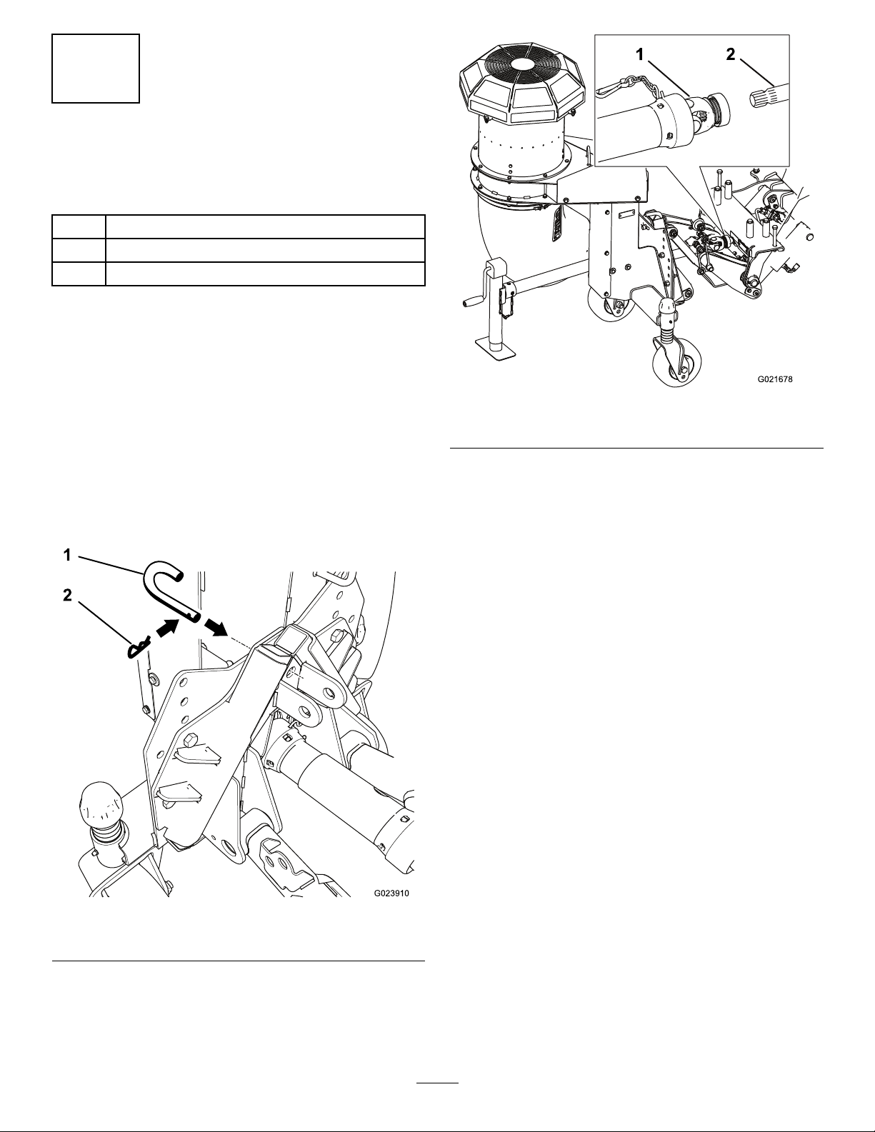
1.Removeanyattachmentfromthefrontofthemachine.
2.Movethetractionunitintopositionbehindthe
attachmentadapter.
3.Raisethetractionunitadapterintotheattachment
adapter.
Figure13
1.Driveshaft2.Quickattachframeshaft
Note:Ifthejackstandisraisedslightlyhigherthan
thecastors,theadapterwillbeeasiertoinstall.
4.Insertthelockingpinthroughtheadaptersandsecure
withahairpincotter(
Figure12).
6.Securethesafetychaintothequickattachframe
(Figure13).
7.Removethedustplugsfromthehydrauliccouplers
andmakesurecouplersarefreeofanydirtor
contamination.
8.Connecttheattachmenthydraulichosecouplerstothe
hydrauliccouplersonthetractionunitrearauxiliary
hydraulicpowerkit.
Important:Wheneverthehydraulichose
couplersaredisconnected,makesurethedust
plugsarecleanedandtheninstalledtoprevent
contaminationfromenteringeitherhydraulic
system.
Figure12
1.Lockingpin2.Hairpincotter
5.Installthedriveshafttothequickattachframeby
slidingthequickcouplerontotheshaft(Figure13).
10
Page 11
5
G021679
1
2
3
4
5
1
G021761
InstallingtheProximitySwitch
Partsneededforthisprocedure:
1Proximityswitchassembly
1
Sensorplate
2
Carriagescrew,5/16x1–1/4inch
2
Flangenut,5/16inch
Procedure
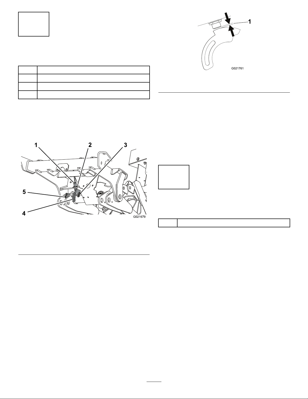
1.Usingtheholeinthebottomofthefrontframe,loosely
mounttheproximityswitchwiththewashersandjam
nuts(Figure14).
Figure15
1.3.8to4.3mm(.150to.170inch)gap
6.Connectthewiresfromtheproximityswitchtothe
frontattachmentupswitchontheGroundsmaster360
electricalaccessorykit
7.Whentheswitchisadjustedcorrectly,theblower
shouldshutoffifraised.
Note:Whenthetractionunitisconvertedbacktoa
mowingmachine,thePTOwillnotcomeonwhenthefront
attachmentisinthefullyraisedposition.Toengagethe
mower,thefrontattachmentmustbefullylowered.
6
GreasingtheMachine
Partsneededforthisprocedure:
Figure14
1.Proximityswitch
2.Jamnutandwasher(2)5.Sensorplate
3.Flangenut(2)
2.Looselymountthesensorplatetotheleftliftarmwith
(2)5/16x1–1/4inchcarriagescrewsandangenuts.
Donottightenthejamnutsatthistime.Positionthe
sensorplateasshowninFigure14.Makesurethe
switchdoesnotcontactthesensorplate.
3.Startthemachineandraisetheblower.Stopthe
machine.
4.Adjustthesensorplateuntilitalignswiththeproximity
switchandtightenthecarriagescrewnuts.Makesureit
doesnotcontacttheproximityswitch.
5.Usingthejamnuts,adjusttheproximityswitchupor
downuntilthegapbetweentheswitchplungerand
thesensorplateis3.8to4.3mm(.150to.170inch)
(
Figure15).Torquethejamnutsto20N-m(15ft-lb)
whenthegapisattained.
4.Carriagescrew(2)
A/RGeneralPurposeLithiumBaseGrease
11
Page 12
ProductOverview
1
2
3
4
g021041
G017857
1
2
4
3
5
7
6
Controls
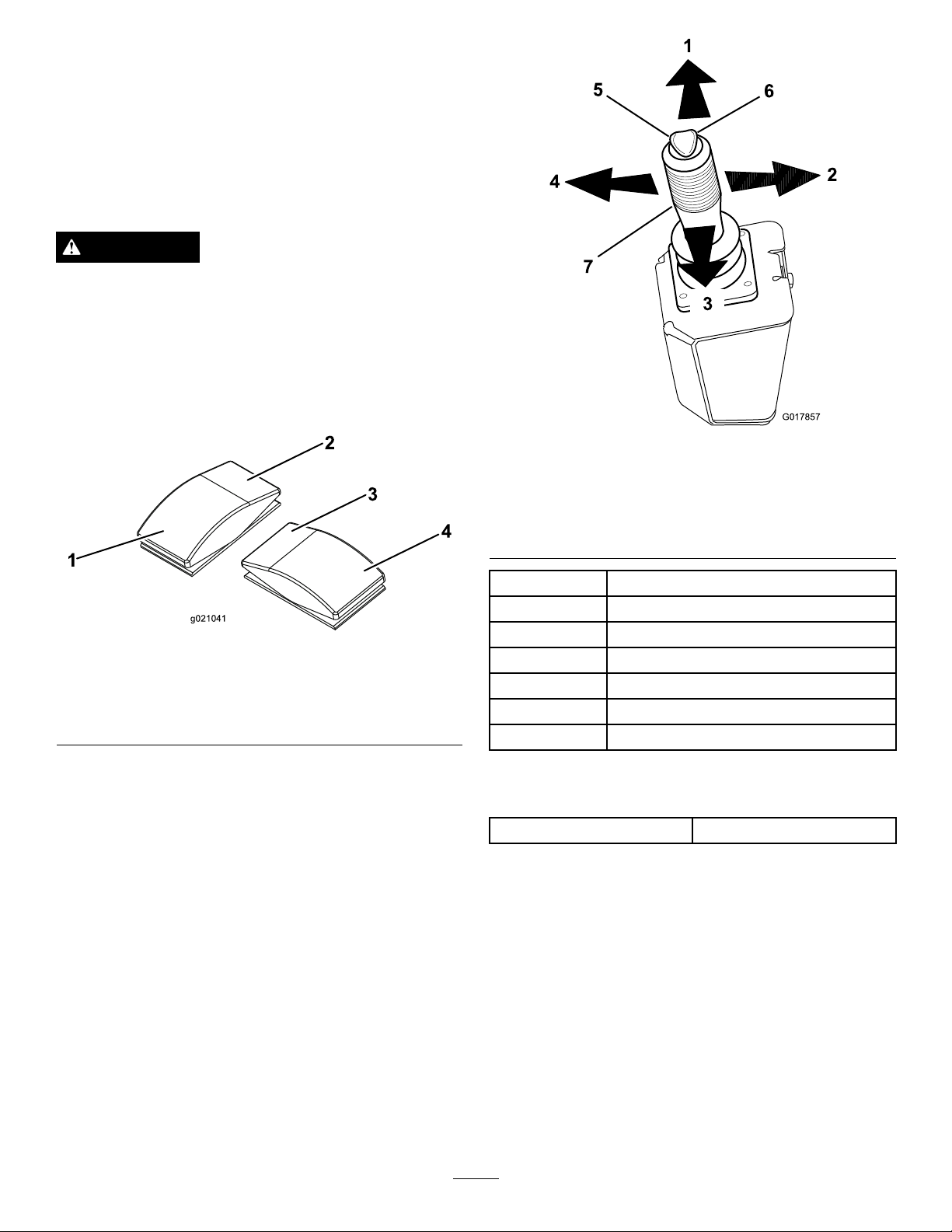
Raise/LowerFrontAttachmentSwitch
Pressthefrontorbackoftherockerswitchtoraiseorlower
thefrontattachment(Figure16).
WARNING
Holdingdownthepowerdownorfrontattachment
lowerswitchcancausesignicanthydraulicsystem
damageandresultinfrontattachmentdamage.
NozzleDirectionSwitch
Pressthefrontorbackoftherockerswitchtorotatethe
nozzletothedesireddirection(Figure16).
Figure17
1.Joystickforward5.Left-handtoggle
2.Joystickright6.Right-handtoggle
3.Joystickback7.Joystick
4.Joystickleft
JoystickActionFunction
ForwardLowerstheblower
Figure16
1.Taptooatfrontattach
down.Holdtopower
down.
2.Raiseandholdfrontattach4.Rotateblowernozzleleft
3.Rotateblowernozzleright
Joystick(Optional)
Note:Allreferencestorightandleftorientationare
determinedbynormaloperatingposition.
BackRaisestheblower
LeftRotatestheblowernozzletotheleft
RightRotatestheblowernozzletotheright
LefttoggleDonotusethisfunction
Righttoggle
Donotusethisfunction
Specications
Weight
171kg.(376lb.)
12
Page 13
Operation
G023971
1
2
Note:Determinetheleftandrightsidesofthemachine
fromthenormaloperatingposition.
ThinkSafetyFirst
Carefullyreadallthesafetyinstructionsanddecalsinthe
safetysection.Knowingthisinformationcouldhelpyouor
anybystandersavoidinjury.
Theuseofprotectiveequipmentforeyes,hearing,feetand
headisrecommended.
CAUTION
Thismachineproducessoundlevelsinexcessof85
dBAattheoperator’searandcancausehearingloss
throughextendedperiodsofexposure.
Wearhearingprotectionwhenoperatingthis
machine.
CAUTION
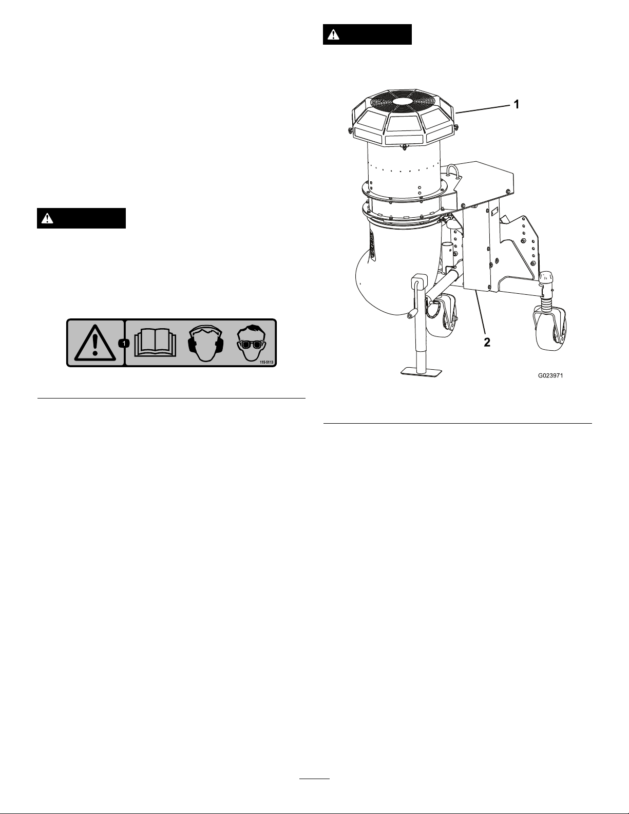
Neveroperatethedebrisblowerwithoutallofthe
guardsinplace(
Figure19).
Figure18
Figure19
1.Fanguard
2.Gearcaseguard
13
Page 14
AdjustingtheBlowerNozzle
OperatingTips
Height
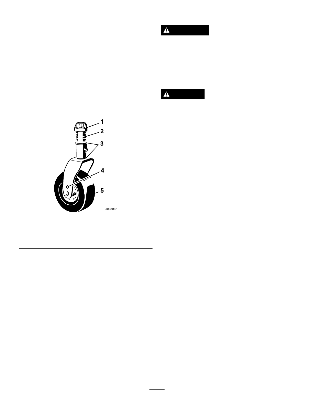
Theblowernozzlecanbeoperatedataheightrangefrom114
to216mm(4.5to8.5inches).Toadjusttheblowernozzle
height,positionthecastorwheelaxlesintheupperorlower
holesofthecastorforksandaddorremoveanequalnumber
ofspacersfromthecastorforks.
1.Starttheengineandraisetheblowerofftheoorso
thecastorwheelscanbechanged.Stoptheengineand
removethekeyaftertheblowerisraised.
2.Positionthecastorwheelaxlesinthesameholesin
bothcastorforks(
axlemountingholestoattainhigherblowernozzle
height.
Figure20).Usethelowercastorfork
WARNING
Dischargedairhasconsiderableforceandcould
causeinjuryorlossoffooting.
•Stayawayfromnozzleopeningwhenmachineis
operating.
•Keepbystandersawayfromnozzleopening
whenmachineisrunning.
DANGER
TIPOVERCANCAUSESERIOUSINJURYOR
DEATH.
•NEVERoperateonsteepslopes.
•Operateonslopesupanddown,neveracross
theface.
•Whengoinguphillordownhill,donotstopor
startsuddenly.
•Stayalertforholesintheterrainorotherhidden
hazards.Toavoidtippingorlossofcontrol,do
notdriveclosetoaditch,creekordropoff.
•Ifthetowvehiclestopswhilegoinguphill,back
slowlydownhill.Donotattempttoturn.
Figure20
1.Tensioningcap4.Axlemountingholes
2.Spacers5.CastorWheel
3.Shims
3.Removethetensioningcapfromthespindleshaft
(Figure20)andslidethespindleoutofthecastorarm.
Putthe2shims(1/8inch)ontothespindleshaftas
theywereoriginallyinstalled.Theseshimsarerequired
toachievealevelacrosstheentirewidthoftheblower.
Slidetheappropriatenumberof1/2inchspacersonto
thespindleshafttogetthedesiredheight;thenslide
thewasherontotheshaft
4.Pushthecastorspindlethroughthecastorarm.Install
theshims(astheywereoriginallyinstalled)andthe
remainingspacersontothespindleshaft.Installthe
tensioningcaptosecuretheassembly.
•Practiceoperatingtheblower.Itisadvisabletoblowthe
samedirectionthewindisblowingtopreventmaterial
fromblowingbackintotheclearedarea.
•Bealert,slowdownandusecautionwhenmakingturns.
Lookbehindandtothesidebeforechangingdirections.
•Beawareoftheblowernozzledirectionanddonotpoint
itatanyone.
•Usecarewhenapproachingblindcorners,shrubs,trees,
orotherobjectsthatmayobscurevision.
•Checkcarefullyforoverheadclearances(i.e.branches,
doorways,electricalwires)beforedrivingunderany
objectsanddonotallowthemtocontacttheblower
screen.
•Reduceyourspeedwhenmakingsharpturnsandwhen
turningonhillsides.
•Beforebackingup,looktotherearandensurethatno
oneisbehindthemachine.
•Donotruntheengineinordirecttheblowernozzleinto
aconnedareawithoutadequateventilation.Exhaust
fumesarehazardousandcouldpossiblybedeadly.
•Usecautionwhenblowingaroundnewlyplantedsodas
theforceoftheaircoulddisruptthegrass.
•Stayawayfromthenozzleopeningwhenthemachine
isoperating.Keepallbystandersawayfromthenozzle
openinganddon’tdirectdischargetowardbystanders.
•Donottakeaninjuryrisk!Whenapersonorpet
appearsunexpectedlyinorneartheoperatingarea,stop
14
Page 15

operation.Carelessoperation,combinedwithterrain
angles,ricochetsorimproperlypositionedguardscanlead
tothrownobjectinjuries.Donotresumeoperationuntil
theareaiscleared.
Important:Raisetheblowerbeforetransporting.If
thenozzleisleftinthedownpositionduringtransport,
thenozzlemaycontactthegroundanddamagetothe
nozzlemayoccur.
15
Page 16
Maintenance
G021632
G021633
1 2
3
4
G022000
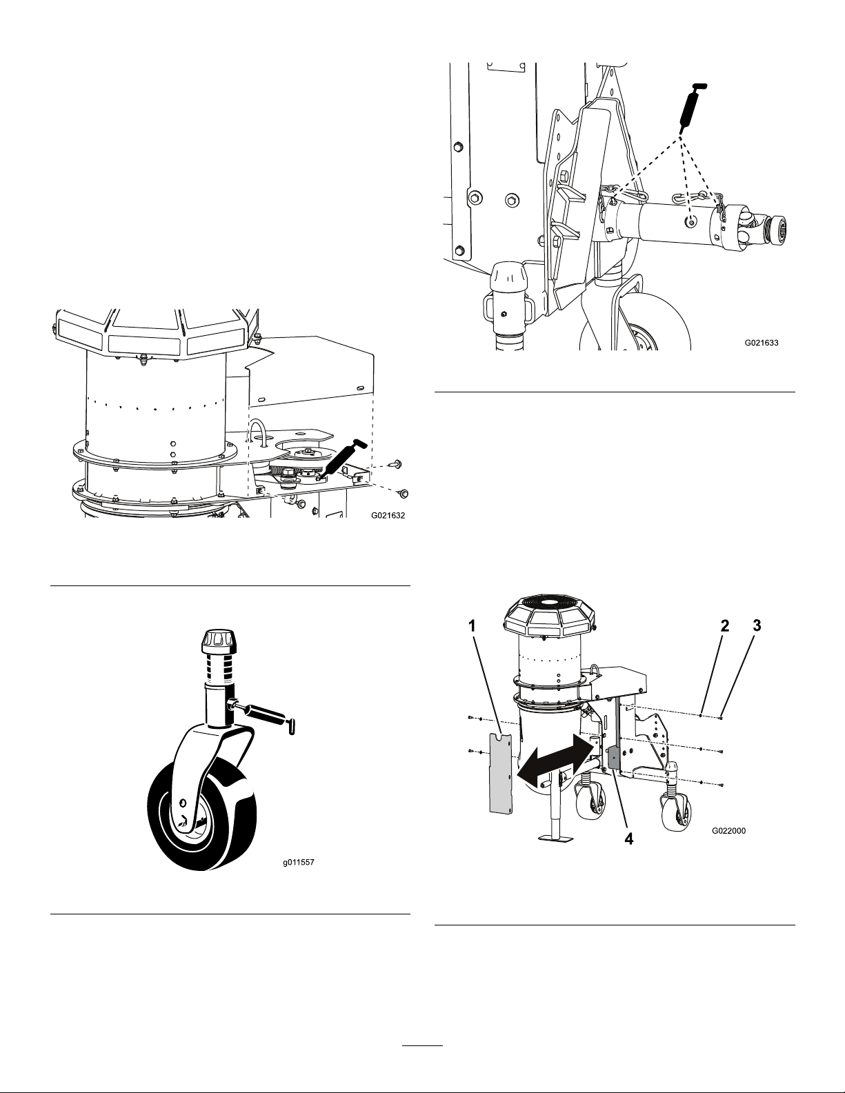
Lubrication
ServiceInterval:Every50hours
Thedebrisblowerhasbearingsandbushingsthatmust
belubricatedregularly.Ifthemachineisoperatedunder
normalconditions,lubricatebearingswithNo.2general
purposelithiumbasegreaseafterevery50hoursofoperation.
Lubricatettingsimmediatelyaftereverywashing,regardless
oftheintervallisted.
Thelubricationpointsareasfollows:
Driveshaft(Figure23)
Drivepulley(
Castorwheelshaft(2)(Figure22)
Figure21)
Figure21
Shownwithcoverremoved
Figure23
CheckingtheGearBox Lubrication
ServiceInterval:Every50hours
1.Positionthemachineandbloweronalevelsurfaceand
lowertheblower.
2.Removethe(5)screwsandwasherssecuringthegear
casecovertotheblower(Figure24).
Figure22
Figure24
1.Cover3.Screw
2.Washer
3.Removethecovertoexposetheblowergearcase
(Figure24).
4.Removethecheck/llplugfromthesideofthegear
box(
Figure25).
16
4.Gearbox
Page 17
1
G022001
2
Figure25
G023909
1
2
1
G021635
G021636
1 2
3
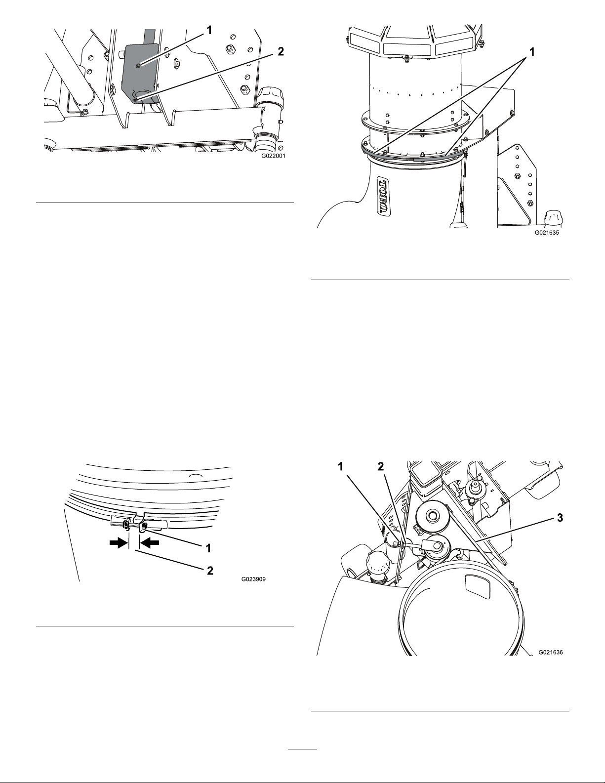
1.Check/llplug
2.Drainplug
5.Checktheoilleveltomakesureitisuptotheplughole
inthegearbox.Ifthelubricantlevelislow ,addenough
SAE80-90weightgearlubetoraisetheleveluptothe
hole.Thegearboxcapacityis207ml(7oz).
6.Installthecheck/llplugtothegearbox.
7.Installthecover.
CheckingtheNozzle
ServiceInterval:Beforeeachuseordaily
CheckingtheNozzleClamp
Checkthenozzleclamp(Figure26)dailytoassureitistight.
Ifthenozzleisdraggedoverobstaclesorthroughlowareasin
theterrainitcouldbeknockedloosefromtheclamp.Tighten
theclampfastenerstomaintainagapof1.3cm(.50inch).
Note:Thenozzlemustrotatefreelywhenmovedbyhand.
Figure27
1.Nozzleguides
AdjustingtheNozzleBelt
ServiceInterval:Aftertherst8hours
Every50hours
Ifthebeltslipswhenchangingthedirectionofthenozzle,an
adjustmenttothebeltisrequired.
1.Checkthetensionbydepressingthebelt,atthecenter
ofthelongestspan,with30N-m.(22lb)offorce
(Figure28).Thebeltshoulddeect4.8mm(.19inch).
Ifthedeectionisincorrect,proceedtothenextstep.
Ifitiscorrect,continueoperation.
1.Nozzleclamp
CleaningtheNozzleGuides
Figure26
2.1.3cm(.50inch)gap
Checkandremoveanygrass,dirtordebrisbuilduparound
andinbetweenthenozzleguides(Figure27).Ifthenozzle
guidesarenotkeepfreeofdebris,thenozzlemaynotrotate
freelywhichcouldcausethemotortostall.
Figure28
1.Flangenut3.Depressbelthere
2.Hexnut
17
Page 18

2.Toincreasethebelttension,loosenthehexnutand
tightentheangenutuntilthedesiredbelttensionis
attained(Figure28).Donotovertighten.
3.Tightenthehexnuttolocktheadjustment.
Storage
1.Removegrassclippings,dirt,andgrimefromthe
externalpartsoftheentireblower.
Important:Y oucanwashthemachinewithmild
detergentandwater.Donotpressurewashthe
machine.Avoidexcessiveuseofwater.
2.Checkandtightenallbolts,nuts,andscrews.Repairor
replaceanypartthatisdamagedordefective.
3.Paintallscratchedorbaremetalsurfaces.Paintis
availablefromyourAuthorizedServiceDealer.
4.Storethemachineinaclean,drygarageorstoragearea.
Usethejackstandtostoretheblowerintheupright
position.Donotlaytheblowerdownontheground.
18
Page 19

DeclarationofIncorporation
TheT oroCompany,8111LyndaleAve.South,Bloomington,MN,USAdeclaresthatthefollowingunit(s)
conform(s)tothedirectiveslisted,wheninstalledinaccordancewiththeaccompanyinginstructionsontocertain
ToromodelsasindicatedontherelevantDeclarationsofConformity.
ModelNo.
44547313000001andUpProForceDebrisBlower
SerialNo.
ProductDescriptionInvoiceDescription
GeneralDescription
PROFORCE
BLOWER-GM360
DebrisBlower
Directive
2006/42/EC,
2000/14/EC
RelevanttechnicaldocumentationhasbeencompiledasrequiredperPartBofAnnexVIIof2006/42/EC.
Wewillundertaketotransmit,inresponsetorequestsbynationalauthorities,relevantinformationonthispartly
completedmachinery.Themethodoftransmissionshallbeelectronictransmittal.
ThismachineryshallnotbeputintoserviceuntilincorporatedintoapprovedToromodelsasindicatedonthe
associatedDeclarationofConformityandinaccordancewithallinstructions,wherebyitcanbedeclaredin
conformitywithallrelevantDirectives.
Certied:EUT echnicalContact:
PeterT etteroo
ToroEuropeNV
B-2260Oevel-Westerloo
Belgium
DavidKlisTel.003214562960
Sr.EngineeringManager
811 1LyndaleAve.South
Bloomington,MN55044,USA
September26,2013
Fax00321458191 1
19
Page 20

TheToroTotalCoverageGuarantee
ALimitedWarranty
ConditionsandProductsCovered
TheToroCompanyanditsafliate,T oroWarrantyCompany,pursuant
toanagreementbetweenthem,jointlywarrantyourT oroCommercial
product(“Product”)tobefreefromdefectsinmaterialsorworkmanship
fortwoyearsor1500operationalhours*,whicheveroccursrst.This
warrantyisapplicabletoallproductswiththeexceptionofAerators
(refertoseparatewarrantystatementsfortheseproducts).Wherea
warrantableconditionexists,wewillrepairtheProductatnocosttoyou
includingdiagnostics,labor ,parts,andtransportation.Thiswarranty
beginsonthedatetheProductisdeliveredtotheoriginalretailpurchaser.
*Productequippedwithanhourmeter.
InstructionsforObtainingWarrantyService
YouareresponsiblefornotifyingtheCommercialProductsDistributoror
AuthorizedCommercialProductsDealerfromwhomyoupurchasedthe
Productassoonasyoubelieveawarrantableconditionexists.Ifyouneed
helplocatingaCommercialProductsDistributororAuthorizedDealer,or
ifyouhavequestionsregardingyourwarrantyrightsorresponsibilities,
youmaycontactusat:
ToroCommercialProductsServiceDepartment
ToroWarrantyCompany
811 1LyndaleAvenueSouth
Bloomington,MN55420-1 196
952–888–8801or800–952–2740
E-mail:[email protected]
OwnerResponsibilities
AstheProductowner ,youareresponsibleforrequiredmaintenance
andadjustmentsstatedinyourOperator'sManual.Failuretoperform
requiredmaintenanceandadjustmentscanbegroundsfordisallowinga
warrantyclaim.
ItemsandConditionsNotCovered
Notallproductfailuresormalfunctionsthatoccurduringthewarranty
periodaredefectsinmaterialsorworkmanship.Thiswarrantydoesnot
coverthefollowing:
•Productfailureswhichresultfromtheuseofnon-Tororeplacement
parts,orfrominstallationanduseofadd-on,ormodiednon-T oro
brandedaccessoriesandproducts.Aseparatewarrantymaybe
providedbythemanufactureroftheseitems.
•Productfailureswhichresultfromfailuretoperformrecommended
maintenanceand/oradjustments.Failuretoproperlymaintainyour
ToroproductpertheRecommendedMaintenancelistedinthe
Operator’sManualcanresultinclaimsforwarrantybeingdenied.
•ProductfailureswhichresultfromoperatingtheProductinan
abusive,negligent,orrecklessmanner.
•Partssubjecttoconsumptionthroughuseunlessfoundtobe
defective.Examplesofpartswhichareconsumed,orusedup,
duringnormalProductoperationinclude,butarenotlimitedto,brake
padsandlinings,clutchlinings,blades,reels,rollersandbearings
(sealedorgreasable),bedknives,sparkplugs,castorwheelsand
bearings,tires,lters,belts,andcertainsprayercomponentssuchas
diaphragms,nozzles,andcheckvalves,etc.
•Failurescausedbyoutsideinuence.Conditionsconsideredtobe
outsideinuenceinclude,butarenotlimitedto,weather,storage
practices,contamination,useofunapprovedfuels,coolants,
lubricants,additives,fertilizers,water,orchemicals,etc.
•Failureorperformanceissuesduetotheuseoffuels(e.g.gasoline,
diesel,orbiodiesel)thatdonotconformtotheirrespectiveindustry
standards.
•Normalnoise,vibration,wearandtear,anddeterioration.
•Normal“wearandtear”includes,butisnotlimitedto,damageto
seatsduetowearorabrasion,wornpaintedsurfaces,scratched
decalsorwindows,etc.
Parts
Partsscheduledforreplacementasrequiredmaintenancearewarranted
fortheperiodoftimeuptothescheduledreplacementtimeforthatpart.
Partsreplacedunderthiswarrantyarecoveredforthedurationofthe
originalproductwarrantyandbecomethepropertyofT oro.T orowill
makethenaldecisionwhethertorepairanyexistingpartorassemblyor
replaceit.T oromayuseremanufacturedpartsforwarrantyrepairs.
DeepCycleandLithium-IonBatteryWarranty:
DeepcycleandLithium-Ionbatterieshaveaspeciedtotalnumberof
kilowatt-hourstheycandeliverduringtheirlifetime.Operating,recharging,
andmaintenancetechniquescanextendorreducetotalbatterylife.Asthe
batteriesinthisproductareconsumed,theamountofusefulworkbetween
chargingintervalswillslowlydecreaseuntilthebatteryiscompletelyworn
out.Replacementofwornoutbatteries,duetonormalconsumption,
istheresponsibilityoftheproductowner.Batteryreplacementmaybe
requiredduringthenormalproductwarrantyperiodatowner’sexpense.
Note:(Lithium-Ionbatteryonly):ALithium-Ionbatteryhasapartonly
proratedwarrantybeginningyear3throughyear5basedonthetime
inserviceandkilowatthoursused.RefertotheOperator'sManualfor
additionalinformation.
MaintenanceisatOwner’sExpense
Enginetune-up,lubrication,cleaningandpolishing,replacementoflters,
coolant,andcompletingrecommendedmaintenancearesomeofthe
normalservicesT oroproductsrequirethatareattheowner’sexpense.
GeneralConditions
RepairbyanAuthorizedT oroDistributororDealerisyoursoleremedy
underthiswarranty .
NeitherTheToroCompanynorT oroWarrantyCompanyisliablefor
indirect,incidentalorconsequentialdamagesinconnectionwiththe
useoftheToroProductscoveredbythiswarranty ,includingany
costorexpenseofprovidingsubstituteequipmentorserviceduring
reasonableperiodsofmalfunctionornon-usependingcompletion
ofrepairsunderthiswarranty.ExceptfortheEmissionswarranty
referencedbelow,ifapplicable,thereisnootherexpresswarranty .
Allimpliedwarrantiesofmerchantabilityandtnessforuseare
limitedtothedurationofthisexpresswarranty .
Somestatesdonotallowexclusionsofincidentalorconsequential
damages,orlimitationsonhowlonganimpliedwarrantylasts,sothe
aboveexclusionsandlimitationsmaynotapplytoyou.Thiswarranty
givesyouspeciclegalrights,andyoumayalsohaveotherrightswhich
varyfromstatetostate.
Noteregardingenginewarranty:
TheEmissionsControlSystemonyourProductmaybecoveredby
aseparatewarrantymeetingrequirementsestablishedbytheU.S.
EnvironmentalProtectionAgency(EPA)and/ortheCaliforniaAir
ResourcesBoard(CARB).Thehourlimitationssetforthabovedonot
applytotheEmissionsControlSystemWarranty.RefertotheEngine
EmissionControlWarrantyStatementsuppliedwithyourproductor
containedintheenginemanufacturer’sdocumentationfordetails
CountriesOtherthantheUnitedStatesorCanada
CustomerswhohavepurchasedT oroproductsexportedfromtheUnitedStatesorCanadashouldcontacttheirToroDistributor(Dealer)toobtain
guaranteepoliciesforyourcountry ,province,orstate.IfforanyreasonyouaredissatisedwithyourDistributor'sserviceorhavedifcultyobtaining
guaranteeinformation,contacttheT oroimporter.
374-0253RevB
 Loading...