

Page 1
FORM NO. 95-9093
Model No. 41443-80001 & UP
Model No. 41442-80001 & UP
Model No. 41441-80001 & UP
Model No. 41440-80001 & UP
OPERATORS
INSTRUCTIONS
SKID SPRAYER
CONTENTS
GENERAL .............................................................................. 2 - 9
SAFETY INSTRUCTIONS ............................................................................................ 2 - 3
PRODUCT IDENTIFICATION ........................................................................................... 4
DECALS ............................................................................................................................ 5
BEFORE SPRAYING ......................................................................................................... 6
NOZZLE SELECTION CHARTS ................................................................................... 7 - 8
STORAGE.......................................................................................................................... 9
ENGINE.............................................................................. 10 - 13
BEFORE OPERATING .................................................................................................... 10
OPERATING INSTRUCTIONS ........................................................................................ 11
MAINTENANCE ....................................................................................................... 12 - 13
STORAGE........................................................................................................................ 13
41441 CENTRIFUGAL PUMP ............................................ 14 - 19
CONTROLS ..................................................................................................................... 14
BEFORE SPRAYING ....................................................................................................... 15
OPERATION .................................................................................................................... 16
PREVENTIVE MAINTENANCE ....................................................................................... 17
MAINTENANCE ....................................................................................................... 18 - 19
41443 DIAPHRAGM PUMP ............................................... 20 - 24
SAFETY INSTRUCTIONS ............................................................................................... 20
CONTROLS ..................................................................................................................... 21
BEFORE SPRAYING ................................................................................................ 22 - 23
AFTER SPRAYING .......................................................................................................... 23
MAINTENANCE .............................................................................................................. 24
41442 PTO CENTRIFUGAL PUMP........................................... 25
CONTROLS ..................................................................................................................... 25
BEFORE SPRAYING ....................................................................................................... 26
PREVENTIVE MAINTENANCE ....................................................................................... 27
MAINTENANCE ....................................................................................................... 28 - 29
©The TORO Company - 1998
All Rights Reserved
Page 2
To assure maximum safety, optimum
performance, and to gain knowledge of the
product, it is essential that you or any other
operator of this Vehicle read and understand
the contents of this manual before the engine
is ever started. Pay particular attention to the
SAFETY INSTRUCTIONS highlighted by the
triangular safety alert symbol.
personal safety instruction. Failure to comply
with the instruction may result in personal
injury.
The safety alert symbol means
CAUTION, WARNING or DANGER -
SAFETY INSTRUCTIONS
Keep this Operators Manual and the Engine Manual in the plastic tube on the side of the Tank Frame.
It is very important that all persons operating this equipment have easy access to these instructions at all
times!
Carefully read and follow the set-up instructions that are provided with this equipment . The installation
of accessories on the TORO Skid Frame, other than those designated and sold for that express purpose
by TORO, may adversely affect the performance and safety characteristics of this equipment.
RECOGNIZE SAFETY INFORMATION
This safety-alert symbol is used to call
attention to a dangerous situation, which
could result in serious injury or death to the
operator or a bystander.
Safety, mechanical and some general information
in this manual are emphasized. DANGER,
WARNING and CAUTION identify safety
messages. Whenever the triangular safety symbol
appears, it is followed by a safety message that
must be read and understood. For more details
concerning safety, read the Safety Instructions on
this page and page 2. IMPORTANT identifies
special mechanical information and NOTE
identifies general information worthy of special
attention.
These instructions are provided as a guide for the
safe operation and maintenance of this equipment.
However, the operators personal safety, as well
as those persons in the work area, will depend on
the careful actions and good judgement of the
operator. To reduce the potential for injury or
death, comply with the following safety
instructions.
BEFORE OPERATING:
1. Operate this machine only after reading and
understanding the contents of this manual. A
replacement manual is available by sending
complete model and serial number to: Hahn
Equipment Co., a subsidiary of The Toro Company,
1625 N. Garvin, Evansville, IN 47711.
2. Learn how to operate the Sprayer and how to
use the controls properly. DO NOT let anyone
operate this equipment without first receiving
thorough instructions.
2
3. Keep all shields, safety devices and decals in
place. If a shield, safety device or decal is
malfunctioning, illegible or damaged, repair or
replace it before operating the machine.
4. Chemicals can injure persons, animals, plants,
soils or other property. To eliminate environmental
damage and personal injury:
A. Obtain proper training before using or
handling chemicals.
B. Select the proper chemical for the job.
C. Follow manufacturers instructions on
chemical container labels. Apply and handle
chemicals as recommended.
D. Handle and apply chemicals with care.
Wear goggles and other necessary protective
equipment. Handle chemicals in well
ventilated areas. Never smoke while handling
chemicals.
E. Properly dispose of chemical container and
unused chemicals.
4. To be sure of optimum performance and safety,
always purchase genuine TORO replacement
parts and accessories. Replacement parts and
accessories made by other manufacturers could
be dangerous. Altering the Skid Sprayer in any
manner may affect the Skid Sprayer's operation,
performance, durability or its use may result in
injury or death. Such use could void the product
warranty of the Toro Company.
5. This equipment should not be modified without
The Toro Companys authorization. Direct any
inquiries to:
Hahn Equipment Co.
1625 N. Garvin
Evansville, IN 47711
Page 3
SAFETY INSTRUCTIONS
6. Since gasoline is highly flammable, handle it
carefully.
A. Use an approved gasoline container.
B. Do not remove cap from fuel tank when
engine is hot or running.
C. Do not smoke while handling gasoline.
D. Fill fuel tank outdoors and to about 1/2
below top of tank, (bottom of filler neck). Do
not overfill.
E. Wipe up any spilled gasoline.
WHILE OPERATING:
Drive the transport vehicle safely.
WARNING
Attaching the trailer sprayer to a vehicle
changes the weight and handling of the
vehicle, and could cause loss of control
resulting in serious injury or death.
Refer to the vehicles operators manual
for tow bar and braking capacities and
do not exceed those recommendations.
Consider the terrain that the trailer
sprayer will be used on when evaluating
the capacities of the tow vehicle. Hills
and slopes will require more braking
power and stopping distance than flat
areas.
1. DO NOT make sudden or sharp turns. DO
NOT suddenly change direction of travel on an
incline, ramp, grade, slope or similar surface.
2. Make certain everyone is clear of the machine
before starting the engine to move the transport
vehicle or to engage the Sprayer Pump drive.
3. Do not touch engine, muffler or muffler shield
while engine is running or soon after it has
stopped. These areas may be hot enough to cause
burns.
4. If equipment begins to vibrate abnormally, stop
immediately. Shut off the Skid Sprayer engine
and disengage all power. Repair all damage
before commencing operation.
MAINTENANCE:
WARNING
The engine exhaust from this product
contains chemicals known to the State of
California to cause cancer, birth defects, or
other reproductive harm.
WARNING: Engine exhaust contains carbon
monoxide which is an odorless, deadly poison.
Do not run engine indoors or in an enclosed
area.
1. Before servicing or making any adjustments
to the Skid Sprayer:
Do not use the fully loaded sprayer in
areas where stopping and vehicle
handling is questionable. The following
chart should be used to adjust the weight
of the sprayer to fit the tow vehicle and
its conditions.
TANK VOL. TRAILER WT. SKID WT.
(GAL) (LBS) (LBS)
110 1620 1385
100 1535 1300
90 1455 1220
80 1370 1135
70 1285 1050
60 1200 965
50 1120 885
Based on the weight of water.
A. Stop the transport vehicle on level surface
and set the parking brake.
B. Disengage all power and wait until all
moving parts have stopped.
C. Shut off the Skid Sprayers engine and
remove wire from spark plug. Make sure wire
cannot contact plug accidentally.
D. Keep hands, feet and clothing away from
all power driven parts.
2. Keep all nuts, bolts and other fasteners
tightened securely. Replace any shields removed
during servicing or adjustments.
3. To reduce potential fire hazard, keep the
engine area free of excessive grass, leaves and
accumulation of dirt.
3
Page 4

PRODUCT IDENTIFICATION
Skid Sprayer
Model No. 41440
Serial No. ____________
Record the serial numbers on your equipment in the space above as soon as possible, as it is necessary
to include this information when ordering service parts or requesting information. Please fill out the
Product Registration Card and return it to:
The TORO Company
8111 Lyndale Ave. South Date Purchased ___________
Minneapolis, MN 55420
SPARK ARRESTOR
When the machine is used or operated on any California forest, brush or grass covered land, a properly
operating spark arrestor must be attached to the muffler. The operator is violating state law, Section 442
Public Resources Code if a spark arrestor is not used.
Briggs & Stratton Engine
Model No. 196432
Type No. 1063 E2
Code No. ____________
All information, illustrations and specifications in this manual are based on the latest product information available at the time
of publication. The right is reserved to make changes at any time without notice.
4
Page 5
SAFETY INSTRUCTIONS
READ YOUR OPERATOR’S MANUAL FOR OPERATING AND
SAFETY INSTRUCTIONS. TO GET A REPLACEMENT MANUAL,
SEND MODEL AND SERIAL NUMBERS TO : THE TORO CO., 8111
LYNDALE AVE. S., MPLS., MN 55420
65-3090
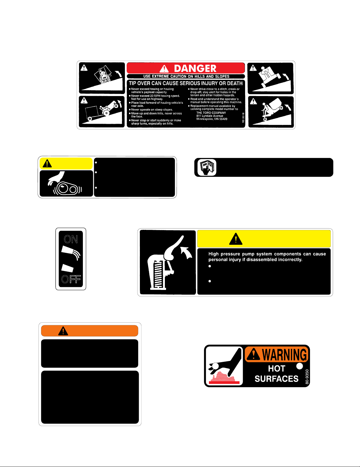
The following safety and instruction decals are installed on the Skid Sprayer. If any become damaged
or illegible, replace them. Decals and part numbers are listed below and in the parts catalog.
Order replacements from your Authorized Toro Distributor.
Part No. 92-3518: Located on front of Tank.
CAUTION
TO AVOID PER SONAL INJURY KEEP
ALL SHIELDS IN PLACE.
DISENGAGE AND SHUT OFF
ENGINE BEFORE SERVICING OR
UNCLOGGING MACHINE.
KEEP HANDS, FEET AND CLOTHI NG
AWAY FROM POWER-DRIVEN PARTS.
Part No. 87-0450: Located on top of Belt Guard.
ON
OFF
Part No. 41174: Located on
Belt Cover.
WARNING
87-0450
Part No. 65-3090: Located on top of Engine Cover.
WARNING
Shut engine off and release pressure at pump before
disconnecting any high pressure components. To release
pressure, lift relief valve at pump.
See operat or’s manual for complete safety and operating
procedures.
Part No. 92-3709: Located on top of Engine Air Cleaner.
(41443 Diaphragm Pump only)
92-3709
EXCEEDING THE TOWING OR HAULING VEHICLE’S
CAPACITY CAN RESULT IN SERIOUS INJURY OR
DEATH.
ALWAYS REFER TO TOWING OR HAULING VEHICLE’S
OPERATOR MANUAL AND THE FOLLOWING CHART
TO DETERMINE MAXIMUM CAPACITY.
TANK VOLUME
(GAL)
110
100
90
80
70
60
50
TRAILER WEIGHT
(LBS)
1620
1535
1455
1370
1285
1200
1120
BASED ON WEIGHT OF WATER
SKID WEIGHT
(LBS)
1385
1300
1220
1135
1050
965
885
Part No. 95-9320: Located on front of Tank.
Part No. 80-9350: Located on Belt Cover.
95-9320
5
Page 6

BEFORE SPRAYING
NOZZLE SELECTION:
See the nozzle charts on page 7 or 8 to be sure
that your spray nozzles have the capacity
necessary to achieve the application rate selected.
To select the proper nozzle, you need to know:
1. Recommended chemical application rate in
gallons per acre, gallons per 1000 sq. ft. or liters
per hectare.
2. Average Vehicle speed in Miles per hour or
kilometers per hour.
3. Nozzle spacing (20 inches or 50 centimeters.)
With this information you can calculate the volume
per minute per nozzle, using the formulas below.
US FORMULA:
G.P.M. =
(Per Nozzle) 5940
TU (Turf) FORMULA:
G.P.M. =
(Per Nozzle) 137
SI (METRIC) FORMULA:
lit/min =
(Per Nozzle) 60,000
Use G.P.M. (lit/min) and Pressure to select
appropriate nozzle from chart on page 7 or 8.
EXAMPLE (US FORMULA):
Application Rate = 75 Gallons/Acre
Vehicle Speed = 4 M.P.H.
Nozzle Spacing = 20 inches
G.P.A. x M.P.H. X 20 ins.
G.P.K. x M.P.H. x 20 ins.
lit/ha x km/h x 50 cm
SYMBOL DEFINITIONS:
GPM - Gallons per minute
lit/min - Liters per minute
dl/min - Deciliter per minute
PSI - Pounds per square inch
kPa - Kilopascal
GPA - Gallons per acre
lit/ha - Liter per hectare
ml/ha - Milliliter per hectare
GPK - Gallons per 1,000 sq. ft.
mm - Millimeters
cm - Centimeters
dm - Decimeters
m - Meter
MPH - Miles per hour
km - Kilometers
km/h - Kilometers per hour
US - Volume per ACRE
SI - Volume per HECTARE
TU - Volume per 1,000 sq. ft.
LIQUID CONVERSIONS
U.S. Gallons x 128 = Fluid Ounces
U.S. Gallons x 3.785 = Liters
U.S. Gallons x 0.83267 = Imperial Gallons
U.S. Gallons x 8.34 = Pounds (Water)
LENGTH
1 millimeter (mm) = 0.039 inch
1 centimeter (cm) = 0.393 inch
1 meter (m) = 3.281 feet
1 kilometer (km) = 0.621 mile
1 inch = 25.4 millimeters; 2.54 centimeters
1 mile = 1.609 kilometers
75 G.P.A. x 4 M.P.H. x 20 = 1.00 G.P.M.
5940 (per nozzle)
With 1.00 G.P.M. and a pressure of 40 P.S.I. you
would select Nozzle No. 95-9188.
EXAMPLE (TU FORMULA):
Application Rate = 1.70 Gal./1000 sq. ft.
Vehicle Speed = 4 M.P.H.
Nozzle Spacing = 20 inches
1.70 G.P.K. x 4 M.P.H. x 20 = 1.00 G.P.M.
137 (per nozzle)
EXAMPLE (SI FORMULA):
Application Rate = 907 lit/hectare
Vehicle Speed = 5 km/h
Nozzle Spacing = 50 cm
907 lit/ha x 5 km/h x 50 = 3.78 lit/min.
60,000 (per nozzle)
With 3.78 lit/min and a pressure at 275 kPa you
would select nozzle No. 95-9188
6
PRESSURE
1 psi = 6.89 kPa
AREA
1 square meter = 10.764 sq. feet
1 hectare (ha) = 2.471 acres; 10,000 sq.meters
1 acre = 0.405 hectare; 43,560 sq. ft.
1 sq. mile = 640 acres; 258.9 hectares
Page 7

TORO TURF-JET NOZZLES
Gallons Per Acre Application Rates
TORO Nozzle Press ure Capac ity
Part No. Number (PSIG) 1 Nozzle
(GPM)
Color Co de 2.5 MPH 3 MPH 3.5 MP H 4 MPH 4.5 MPH 5 MPH 5. 5 MPH 6 MPH
20 0.14 16.6 13.9 11.9 10.4 9.2 8.3 7.6 6.9
95-9221 Yellow 30 0.17 20.2 16.8 14.4 12.6 11.2 10.1 9.2 8.4
40 0.20 23.8 19.8 17.0 14.9 13.2 11.9 10.8 9.9
50 0.22 26.1 21.8 18.7 16.3 14.5 13.1 11.9 10.9
20 0.28 33 28 24 21 18 17 15 14
95-9222 Red 300.354235302623211917
40 0.40 48 40 34 30 26 24 22 20
50 0.45 53 45 38 33 30 27 24 22
20 0.35 42 35 30 26 23 21 19 17
95-9223Brown300.435143363228262321
40 0.50 59 50 42 37 33 30 27 25
50 0.56 67 55 48 42 37 33 30 28
20 0.42 50 42 36 31 28 25 23 21
95-9224 Gray 30 0.52 62 51 44 39 34 31 28 26
40 0.60 71 59 51 45 40 36 32 30
50 0.67 80 66 57 50 44 40 36 33
20 0.57 68 56 48 42 38 34 31 28
95-9225White 300.698268595146413734
40 0.80 95 79 68 59 53 48 43 40
500.8910688766659534844
20 0.71 84 70 60 53 47 42 38 35
95-9188 Light Blue 30 0.87 103 86 74 65 57 52 47 43
401.0011999857466595450
50 1.12 133 111 95 83 74 67 60 55
20 1.06 126 105 90 79 70 63 57 52
95-9226 Light Green 30 1.30 154 129 110 97 86 77 70 64
40 1.50 178 149 127 111 99 89 81 74
50 1.68 200 166 143 125 111 100 91 83
Gallons per Acre at 20" Spacings
Gallons Per 1000 Sq. Ft. Application Rates
TORO Nozzle Press ure Capac ity
Part No. Number (PSIG) 1 Nozzle
(GPM)
Color Co de 2.5 MPH 3 MPH 3.5 MP H 4 MPH 4.5 MPH 5 MPH 5. 5 MPH 6 MPH
20 0.14 0.38 0.32 0.27 0.24 0.21 0.19 0.17 0.16
95-9221 Yellow 30 0.17 0.46 0.39 0.33 0.29 0.26 0.23 0.21 0.19
40 0.20 0.54 0.45 0.39 0.34 0.30 0.27 0.25 0.23
50 0.22 0.60 0.50 0.43 0.37 0.33 0.30 0.27 0.25
20 0.28 0.76 0.63 0.54 0.48 0.42 0.38 0.35 0.32
95-9222 Red 30 0.35 0.95 0.79 0.68 0.60 0.53 0.48 0.43 0.40
40 0.40 1.09 0.91 0.78 0.68 0.60 0.54 0.49 0.45
50 0.45 1.22 1.02 0.87 0.77 0.68 0.61 0.56 0.51
20 0.35 0.95 0.79 0.68 0.60 0.53 0.48 0.43 0.40
95-9223 Brow n 30 0.43 1.17 0 .97 0.84 0.73 0.65 0.58 0.53 0.49
40 0.50 1.36 1.13 0.97 0.85 0.76 0.68 0.62 0.57
50 0.56 1.52 1.27 1.09 0.95 0.85 0.76 0.69 0.63
20 0.42 1.14 0.95 0.82 0.71 0.63 0.57 0.52 0.48
95-9224 Gray 30 0.52 1.41 1.18 1.01 0.88 0.79 0.71 0.64 0.59
40 0.60 1.63 1.36 1.17 1.02 0.91 0.82 0.74 0.68
50 0.67 1.82 1.52 1.30 1.14 1.01 0.91 0.83 0.76
20 0.57 1.55 1.29 1.11 0.97 0.86 0.78 0.70 0.65
95-9225 White 30 0.69 1.88 1.56 1.34 1.17 1.04 0.94 0.85 0.78
40 0.80 2.18 1.81 1.55 1.36 1.21 1.09 0.99 0.91
50 0.89 2.42 2.02 1.73 1.51 1.34 1.21 1.10 1.01
20 0.71 1.93 1.61 1.38 1.21 1.07 0.97 0.88 0.80
95-9188 Light Blue 30 0.87 2.37 1.97 1.69 1.48 1.31 1.18 1.08 0.99
40 1.00 2.72 2.27 1.94 1.70 1.51 1.36 1.24 1.13
50 1.12 3.05 2.54 2.18 1.90 1.69 1.52 1.38 1.27
20 1.06 2.88 2.40 2.06 1.80 1.60 1.44 1.31 1.20
95-9226 Light Green 30 1.30 3.54 2 .95 2.53 2.21 1.96 1 .77 1.61 1.47
40 1.50 4.08 3.40 2.91 2.55 2.27 2.04 1.85 1.70
50 1.68 4.57 3.81 3.26 2.86 2.54 2.28 2.08 1.90
Gallons per 1000 Sq. Ft. at 20" S pacings
7
Page 8

TORO TURF-JET NOZZLES
Liters Per Hectare Application Rates
TORO Nozzle Pressure Capacity
Part No. Number (kPa) 1 Nozzle
(L/min)
C ol or Code 4 km /h 5 km/h 6 km/h 7 km/h 8 km / h 9 km/h 10 km/h 11 km/h
150 0.53 159 127 106 91 80 71 64 58
95-9221 Yellow 200 0.64 192 154 128 110 96 85 77 70
275 0.76 228 182 152 130 114 101 91 83
350 0.83 249 199 166 142 125 111 100 91
150 1.06 318 254 212 182 159 141 127 116
95-9222 Red 200 1.32 396 317 264 226 198 176 158 144
275 1.51 453 362 302 259 227 201 181 165
350 1.70 510 408 340 291 255 227 204 185
150 1.40 420 336 280 240 210 187 168 153
95-9223 Brow n 200 1.61 483 386 322 276 242 215 193 176
275 1.89 567 454 378 324 284 252 227 206
350 2.13 639 511 426 365 320 284 256 232
150 1.67 501 401 334 286 251 223 200 182
95-9224 Grey 200 1. 93 579 463 386 331 290 257 232 211
275 2.27 681 545 454 389 341 303 272 248
350 2.56 768 614 512 439 384 341 307 279
150 2.23 669 535 446 382 335 297 268 243
95-9225 White 200 2.58 774 619 516 442 387 344 310 281
275 3.02 906 725 604 518 453 403 362 329
350 3.41 1023 818 682 585 512 455 409 372
150 2.79 837 670 558 478 419 372 335 304
95-9188 Light Blue 200 3.22 966 773 644 552 483 429 386 351
275 3.78 1134 907 756 648 567 504 454 412
350 4.28 1284 1027 856 734 642 571 514 467
150 4.18 1254 1003 836 717 627 557 502 456
95-9226 Light Green 200 4.84 1452 1162 968 830 726 645 581 528
275 5.67 1701 1361 1134 972 851 756 680 619
350 6.40 1920 1536 1280 1097 960 853 768 698
Li ters per Hectare a t 50 cm Spacin gs
8
Page 9

STORAGE
FLUSH PUMP AFTER USE
One of the most common causes for faulty pump
performance is gumming or corrosion inside the
pump. Flush the pump and entire system with a
solution that will chemically neutralize the liquid
pumped. Mix according to chemical
manufacturers directions. This will dissolve most
residue remaining in the pump, leaving the inside
of the pump clean for the next use.
TO PREVENT CORROSION
IMPORTANT: FREEZING TEMPERATURES
MAY DAMAGE THE PUMP & CONTROL VALVE
IF THE WATER IS NOT DRAINED
COMPLETELY!
SERVICING AFTER STORAGE:
Flush the entire spraying system with clean, clear
water and detergent.
Flush the entire spraying system again with clean,
clear water to rinse.
After cleaning the pump as directed above, flush
it with a permanent type automobile antifreeze
(Prestone, Zerex, etc.) containing a rust inhibitor.
Use a 50% solution - that is, half antifreeze and
half water, or fill pump with FLUID FILM and then
drain it. A protective coating of FLUID FILM will
remain on the inner pump surfaces. Save the
excess FLUID FILM for the next application. Plug
the ports to keep out air during storage. For short
periods of idleness, noncorrosive liquids may be
left in the pump, BUT AIR MUST BE KEPT OUT.
Plug ports or seal port connections.
Drain entire spraying system.
STORAGE AND DISPOSAL OF
CHEMICALS:
Follow chemical manufacturers recommendations
for storage and disposal of chemicals.
9
Page 10
BEFORE OPERATING
ENGINE
FILL ENGINE CRANKCASE WITH OIL:
IMPORTANT! The Skid Sprayer is shipped from
the factory without oil in the engines crankcase.
1. Position the Skid Sprayer on a level surface.
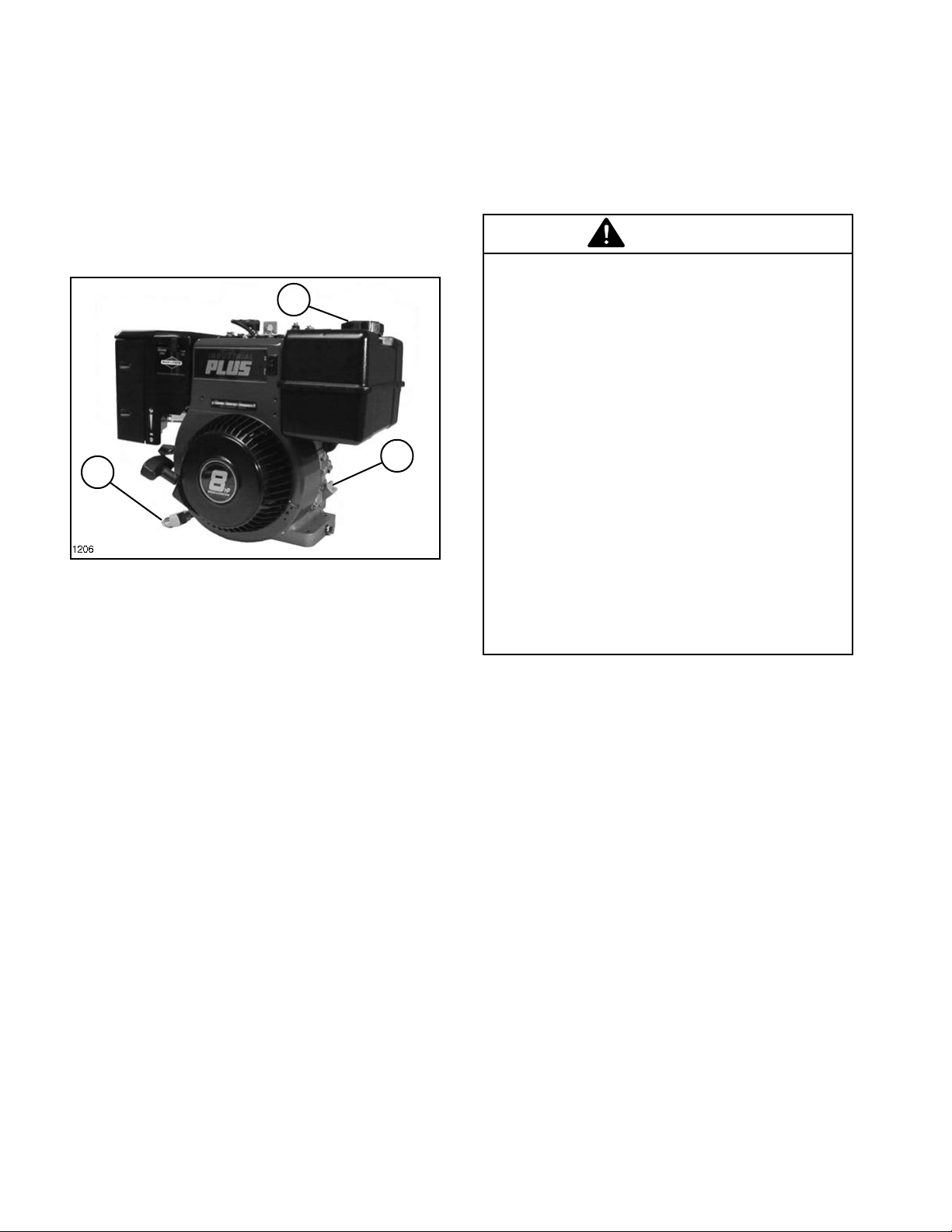
2. Clean the area around the oil fill/check plug
and remove it.
2
1
3
FIG. 1
1. Oil Fill/Check Plug 2. Fuel Tank Cap
3. Oil Drain
3. Insert a funnel into the oil fill tube and slowly
pour engine oil into the crankcase. The engine
uses any high-quality oil having the American
Petroleum Institute-API - service classification
SE, SF or SG. See viscosity on page 12 chart for
recommended weight to use. The capacity of the
crankcase is approximately 44 ounces (1.3 L).
4. The level should be up to, but not over, the
point of overflowing the filler neck.
FILL FUEL TANK WITH GASOLINE:
Fuel tank capacity is approximately 4 U.S. quarts
(3.8 L).
WARNING
Because gasoline is flammable, caution
must be used when storing or handling it.
Do not fill fuel tank while engine is running,
hot or when machine is in an enclosed area.
Vapors may build up and be ignited by a
spark or flame source many feet away. DO
NOT SMOKE while filling the fuel tank to
prevent the possibility of an explosion.
Always fill fuel tank outside and wipe up any
spilled gasoline before starting engine. Use
a funnel or spout to prevent spilling gasoline,
and fill tank to about 1/2 inch (13 mm) below
the filler neck. Store gasoline in a cool, well-
ventilated place; never in an enclosed area
such as a hot storage shed. To ensure
volatility, do not buy more than a 30 day
supply of gasoline. Gasoline is a fuel for
internal combustion engines; therefore, do
not use it for any other purpose. Since many
children like the smell of gas, keep it out of
their reach because the fumes are explosive
and dangerous to inhale.
1. Clean area around fuel tank cap so foreign
matter cannot enter tank when cap is removed.
See FIG. 1.
2. Remove cap from fuel tank and fill tank with
unleaded gasoline to within 1/2" (13 mm) from top
of tank. Then reinstall fuel tank cap.
5. Reinstall the oil fill/check plug and tighten
securely. Make sure it is tightened to 13 ft. lbs.
(17.6 N m) torque.
IMPORTANT! Check the oil level every five (5)
operating hours or each time the engine is
started. For a new engine, drain the oil and
replace it after the first five (5) hours of
operation: thereafter, under normal conditions,
change oil after every 25 hours of operation.
Change the oil more frequently when the engine
is operated in dusty or dirty conditions.
10
3. Wipe up any gasoline that may have spilled.
Page 11
ENGINE OPERATING INSTRUCTIONS
BEFORE STARTING ENGINE TO BEGIN THE
DAYS SPRAYER APPLICATION:
1. Check the engine crankcase oil.
2. Check the Air Cleaner.
3. Check cooling air intake areas.
4. Check the fuel tank.
STARTING THE ENGINE:
1. Set the Engine Stop Switch to ON.
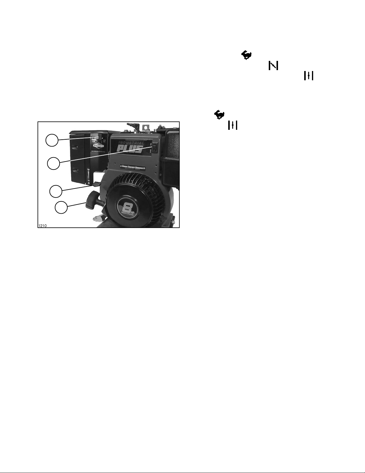
1
2
3
4
2. For a Cold Engine: Place the throttle control
to the FAST
control to the CHOKE position. Gradually
return the choke control to the RUN
after the engine starts and warms up. See FIG. 2.
For a Warm Engine: (normal operating
temperatures) Place the throttle control to the
fast
the RUN position.
3. Pull the Starter Handle with a smooth, steady
motion. Pull the handle straight out to avoid excess
rope wear.
positions. Move the Choke Control to
positions. Move the choke
position
FIG. 2
1. Choke Control 3. Throttle Control
2. Stop Switch 4. Starter Handle
11
Page 12
ENGINE MAINTENANCE
ENGINE LUBRICATION:
IMPORTANT! AFTER THE INITIAL RUN-IN
PERIOD (APPROXIMATELY 5 HOURS) AND
EVERY 25 HOURS THEREAFTER.
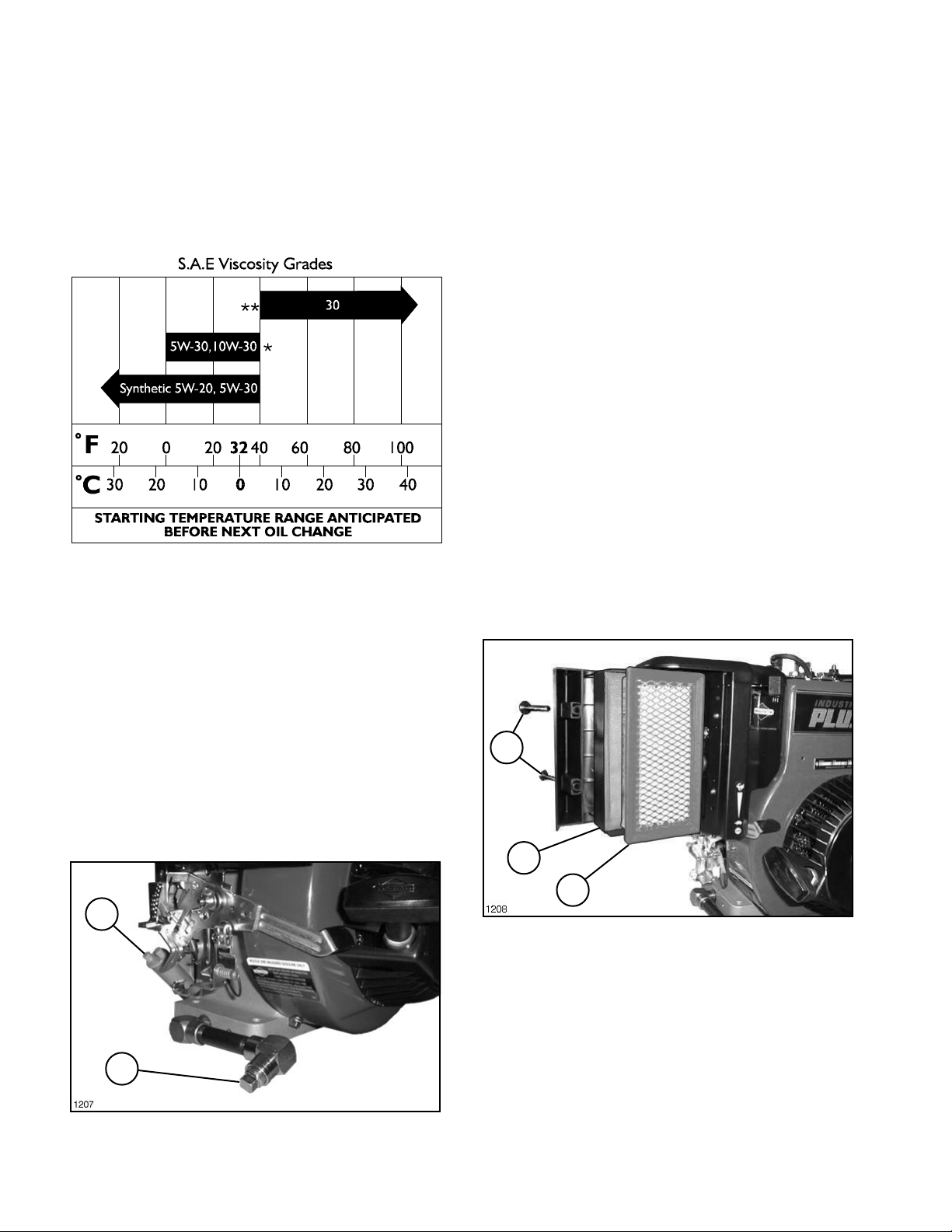
1. Change the oil in the engines crankcase.
Change oil while the engine is warm. Refill with
new oil as recommended in the chart below.
1205
* Air cooled engines run hotter than automotive
engines. Use of multi-viscosity oils (10W-30, etc.)
above 40 F (4 C) will result in high oil consumption
and possible engine damage. Check oil more
frequently if using these type oils.
AFTER EVERY 5 HOURS OR DAILY:
1. Check the oil level in the engines crankcase
before engine start-up, while engine is cool. Have
the machine on a level surface.
2. Clean the area around the oil/fill check plug
and remove it.
3. The level should be up to but not over, the point
of overflowing the filler neck.
4. If the level is low, add API service
classification SE, SF or SG. See viscosity chart
for the recommended weight.
5. Reinstall the oil fill/check plug and tighten
securely. Make sure it is tightened to 13 ft. lbs.
(17.6 Nm) torque.
IMPORTANT! Keep the area around the fill tube
clean, to prevent dirt from falling into the engine.
AIR CLEANER:
Clean the Pre-Cleaner after every 25 hours of
operation. Clean more often in extreme dusty or
dirty conditions. Replace air cleaner parts if very
dirty.
1. Loosen Cover Screws and remove Cover,
Pre-Cleaner and Cartridge. See FIG. 3.
** SAE 30 oil, if used below 40°F (4°C) will result
in hard starting and possible engine bore damage
due to inadequate lubrication.
Oil Capacity: Approximately 44 ounces or 1.3
liters.
2. Remove the pipe plug in the end of the oil drain
pipe and let oil flow into a drain pan. When oil
stops, reinstall drain plug. See FIG. 2.
1
2
FIG. 2
1. Oil Fill 2. Drain Plug
12
1
2
3
FIG. 3
1. Cover Screws 3. Cartridge
2. Pre-Cleaner
2. Wash Pre-Cleaner in liquid detergent and
water. Squeeze dry in clean cloth. Saturate in
engine oil. Squeeze in clean, absorbent cloth to
remove ALL EXCESS oil. If very dirty or damaged,
replace it.
3. Clean Cartridge by tapping gently on flat
surface. If very dirty or damaged, replace it. Do
NOT oil Cartridge.
4. Replace Cartridge, Pre-Cleaner and Cover.
Secure Cover with the (2) Cover Screws.
Page 13
CHECK SPARK PLUG:
ENGINE MAINTENANCE (Contd)
CLEAN AIR INTAKE/COOLING AREAS:
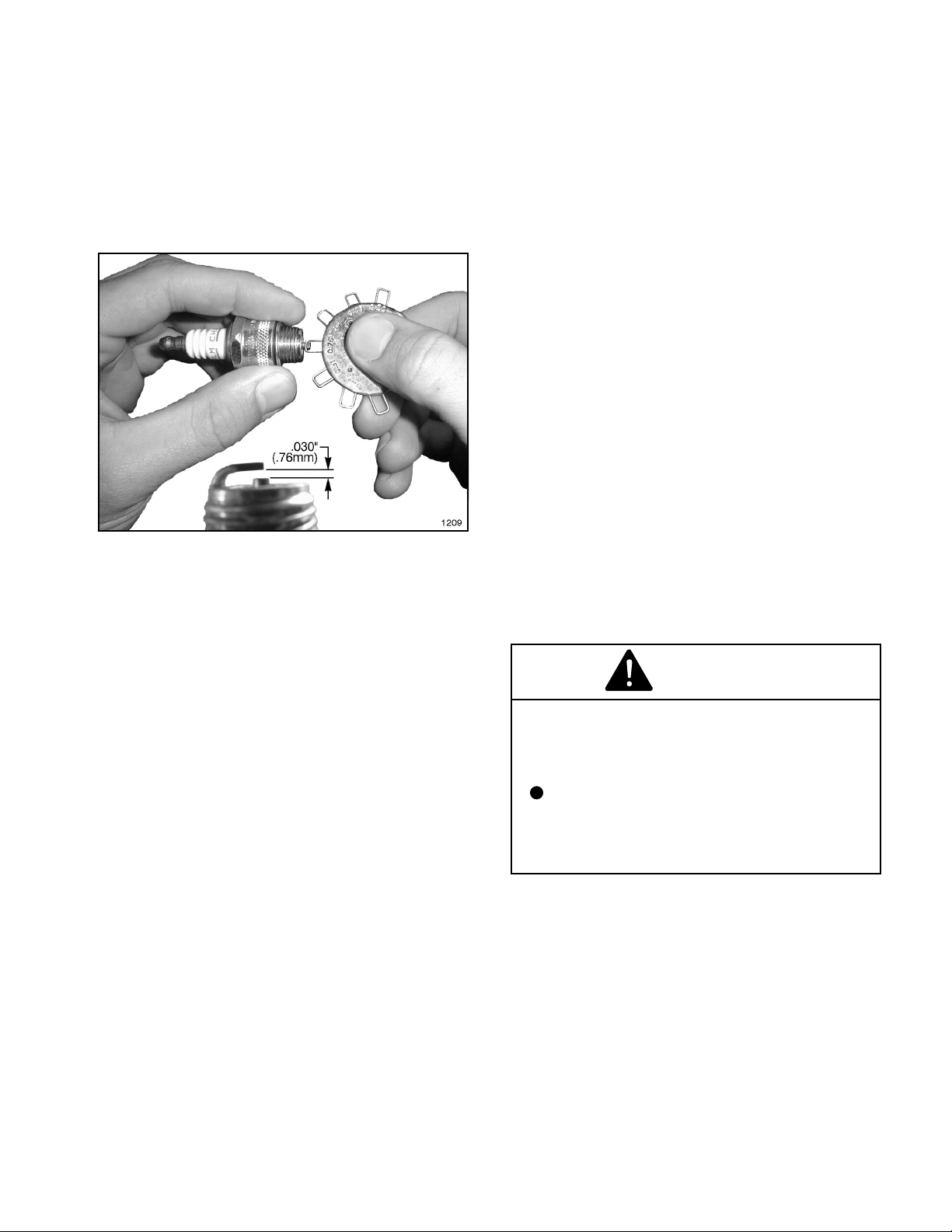
Every 50 hours of operation, clean the area around
the base of the plug and check its condition. Reset
the gap to .030 in. (0.76 mm) or replace with a
new resistor spark plug as necessary. See FIG. 4.
Do not blast clean. Clean by scraping or wire
brushing and washing with a commercial solvent.
FIG. 4
To insure proper cooling, make sure the screen,
cooling fins and other external surfaces of the
engine are kept clean at all times.
NOTE: Operating the engine with a blocked
screen, dirty or plugged cooling fins, and/or
cooling shrouds removed, will cause engine
damage due to overheating.
Every 100 hours of operation (more often under
dusty, dirty conditions), remove the blower housing
and other cooling shrouds. Clean the cooling fins
and external surfaces as necessary. Make sure
the cooling shrouds are reinstalled.
ENGINE STORAGE
If Skid Sprayer is stored over 30 days the engine
needs to be protected or drained of fuel to prevent
gum from forming in the fuel system or essential
carburetor parts. See the B & S Engine Manual
for complete storage instructions.
DANGER
GASOLINE IS HIGHLY FLAMMABLE AND
CAN CAUSE SERIOUS INJURY OR DEATH
IF IGNITED.
Never store a machine with gasoline
in the tank or inside a building where
gasoline fumes may reach an open
flame or spark.
13
Page 14
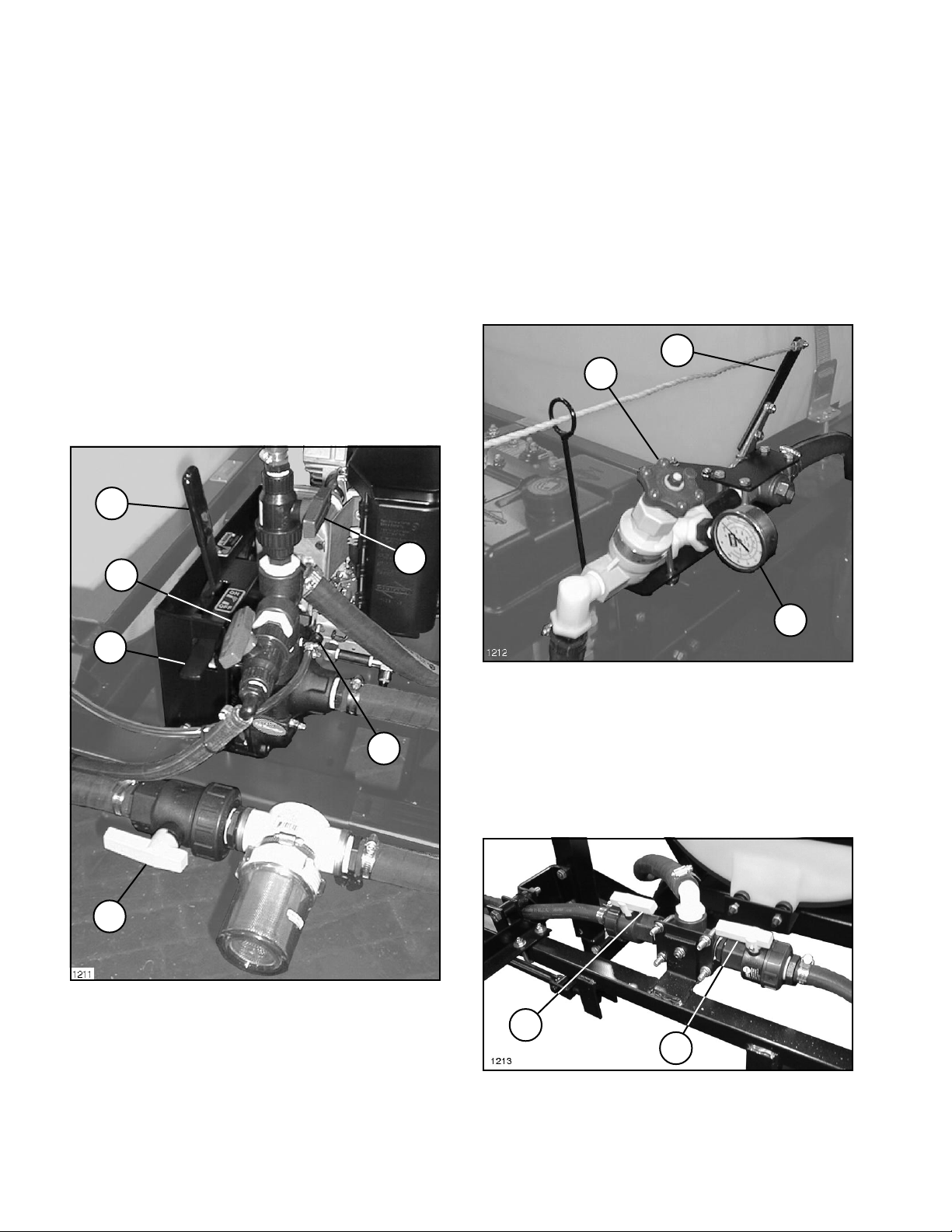
CONTROLS
41441 CENTRIFUGAL PUMP
PUMP ENGAGEMENT LEVER: Engages and
disengages centrifugal pump belt drive.
PUMP ENGAGEMENT RELEASE LEVER:
Releases the Pump Engagement Lever to allow
pump to be engaged.
AGITATOR VALVE HANDLE: Opens and closes
the Agitator Valve to activate, adjust or stop the
agitation of the spray solution in the Tank.
SUCTION VALVE HANDLE: Opens and closes
the Suction Line Valve. Close during maintenance
to the Suction Line Strainer or Centrifugal Pump.
IMPORTANT! The Pump will be damaged if it
is activated with the Suction Line Valve closed,
or before the tank contains enough liquid to
flood the pump.
1
RATCHET VALVE HANDLE: Opens and closes
the Ratchet Valve, starting or stopping flow to
Booms.
PRESSURE ADJUST VALVE HANDLE: Controls
spray pressure. Turn clockwise to decrease
pressure and counterclockwise to increase
pressure.
PRESSURE GAUGE: Shows spray pressure when
Ratchet Valve is open. Shows deadhead pressure
when the Ratchet Valve is closed.
1
3
6
3
2
5
4
FIG. 5
1. Pump Engagement 4. Suction Valve Handle
Lever (open)
2. Pump Engagement 5. Bleed Valve
Release Lever 6. Optional Spray Gun
3. Agitator Valve Handle Valve Handle (closed)
(open)
2
FIG. 6
1. Ratchet Valve Handle 3. Pressure Adjust Valve
2. Pressure Gauge Handle
LEFT BOOM SHUTOFF VALVE HANDLE: Starts
or stops flow to left Boom.
RIGHT BOOM SHUTOFF VALVE HANDLE: Starts
or stops flow to right Boom.
1
2
FIG. 7
1. Left Boom Shutoff 2. Right Boom Shutoff
Valve (open) Valve (open)
14
Page 15
INITIAL SYSTEM SET-UP:
BEFORE SPRAYING
41441 CENTRIFUGAL PUMP
FILL THE FRESH WATER WASH TANK
1. Fill the Tank with clean, clear water and open
the Suction Line Valve. See FIG. 5.
IMPORTANT: The pump will be damaged if it is
activated before it is completely filled with
liquid. Be certain the suction line valve is open
and liquid has reached the pump.
2. Park vehicle on level surface and set the
parking brake. Move the Pump Engagement Lever
to the OFF position. See Fig. 5. Start the engine
as instructed in the ENGINE OPERATING
INSTRUCTIONS section.
3. Open Pressure Adjust Valve completely. See
Fig. 6.
4. Move the Pump Engagement Lever to the ON
position.
5. Assure that the Ratchet Valve is closed. See
Fig. 6.
6. Using Engine Throttle set the Pressure Gauge
to 10 P.S.I. above the desired operating pressure.
7. Assure that both Boom Shutoff Valves are
open. See Fig. 7.
NOTE: Fill Fresh Water Wash Tank with clean
water only. Check to assure tank is full before
each operation.
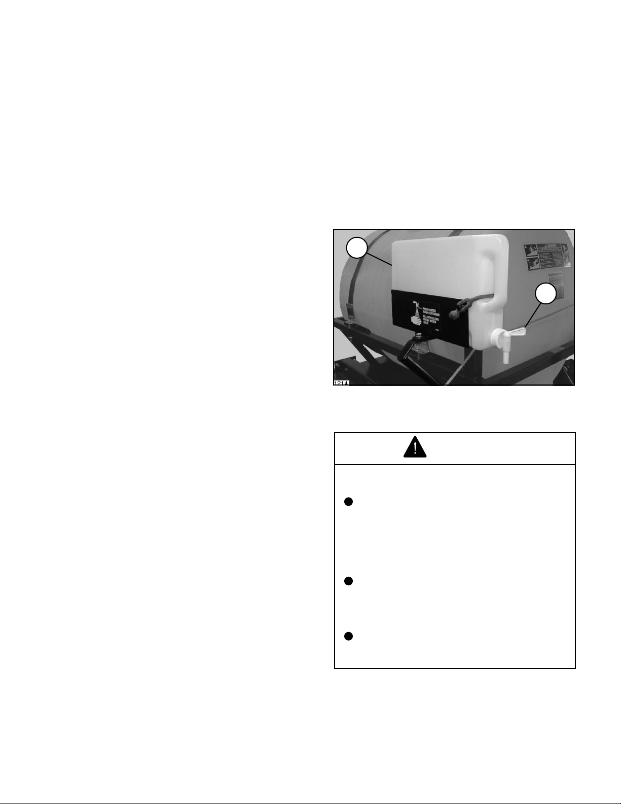
In case of chemical contact with skin or eyes, a
fresh water wash tank has been installed on the
Tank Saddle.
1. Turn Tank Spigot to on position. See FIG. 4.
2. Hold contaminated area directly under water
stream.
1
2
FIG. 8
1. Fresh Water Wash Tank 2. Tank Spigot
8. Open Ratchet Valve to begin spraying water
from the booms.
NOTE: Ratchet Valve must be fully actuated in
order to open or close valve completely.
9. Verify the Pressure Gauge reads the desired
spray pressure. If necessary, decrease pressure
by turning the Pressure Adjust Valve Handle
clockwise or increase pressure by increasing
Throttle Control.
NOTE: This entire procedure should be
repeated whenever changing operating
pressure, nozzles, speed, chemical, etc.
FILLING THE SOLUTION TANK:
WARNING
CHEMICALS ARE HAZARDOUS AND CAN
CAUSE PERSONAL INJURY!
Carefully read the directions printed on
the chemical manufacturers labels
before handling chemicals. Instructions
on chemical manufacturers container
labels, regarding mixing proportions,
should be read and strictly followed.
Keep spray material from skin. If spray
material comes in contact with body,
wash it off immediately with clean water
and detergent.
Always wear goggles and other
protective equipment as recommended
by the Chemical Manufacturer.
IMPORTANT: Do not add chemical to Tank until
just before use. The concentrate should not be
poured into an empty Tank. Fill Tank at least one-
half full with clean, clear water, add chemical
concentrate and finish filling Tank with water.
Follow the chemical manufacturers
instructions for mixing spray solution to obtain
desired application rate.
15
Page 16

USING THE SPRAYER:
OPERATION
41441 CENTRIFUGAL PUMP
AFTER SPRAYING:
IMPORTANT: Check all of your equipment...
make sure that all components are clean,
including the Tank, Pump, Strainer, Check
Valves, Hoses, Nozzles, Spray Tips and Suction
Line Strainer.
1. Start the engine as instructed in the ENGINE
OPERATING INSTRUCTIONS section.
2. Engage the Pump and use the Ratchet Valve
to start and stop boom spray while spraying.
IMPORTANT! While operating the Sprayer:
Do not overlap areas that have been sprayed
previously.
Watch for plugged Nozzles. Replace all worn
Nozzles or those producing streaky or uneven
patterns.
3. Stop the spray flow before stopping the
Vehicle.
IMPORTANT! Pump can be damaged if run dry.
Be prepared to disengage pump before tank is
empty. DO NOT spray on slopes or hill sides
with less than 10 gallons of spray solution in
tank.
It is extremely important to carefully wash and
clean the Tank after every use.
Not only the Tank but the Pump, Hoses, Nozzles,
Screens, Filters, and the exterior of the Sprayer
also should be cleaned.
Flush Pump After Use
One of the most common causes for faulty pump
performance is "gumming" or corrosion inside the
pump. Flush the pump and entire system with a
solution that will chemically neutralize the liquid
pumped. Mix according to the chemical
manufacturer's directions. This will dissolve most
residue remaining in the pump, leaving the inside
of the pump clean for the next use.
A minimum of three 50 gallon rinses usually is
required for all components of the Sprayer. The
addition of a detergent cleaner may be advisable
in the initial washing. Directions for such an
addition, if required, are included on the chemical
container.
Cleaning of the Sprayer should be accomplished
in an area where there is no potential for the
chemicals to be washed off in surface water or to
enter subsurface drainage systems.
When Sprayer is not to be used for an extended
period, refer to the STORAGE section of this
Manual for the detailed instructions to prevent
damage to the components.
16
Page 17
PREVENTIVE MAINTENANCE
41441 CENTRIFUGAL PUMP
Preventative maintenance is most important to
assure long life of the Manual Spray System. The
following maintenance procedures should be
followed on a regular basis:
BELT TENSION:
WARNING
Flush the entire spraying system as described on
page 16 after each use. Failure to clean the system
can result in a chemical residue which can plug
the Control Valve, Hoses and/or Nozzle Tips, and
seriously damage the Centrifugal Pump.
Wash spray nozzles thoroughly with water. Blow
out orifice, clean and dry. If orifice remains
clogged, clean it with a soft bristled brush... never
use a metal object.
Check all of the nozzles frequently to spot any
inconsistencies in the spray pattern. Worn nozzle
orifices which allow a greater volume of spray
material to flow through the nozzle can cause an
expensive loss in chemical and/or turf damage.
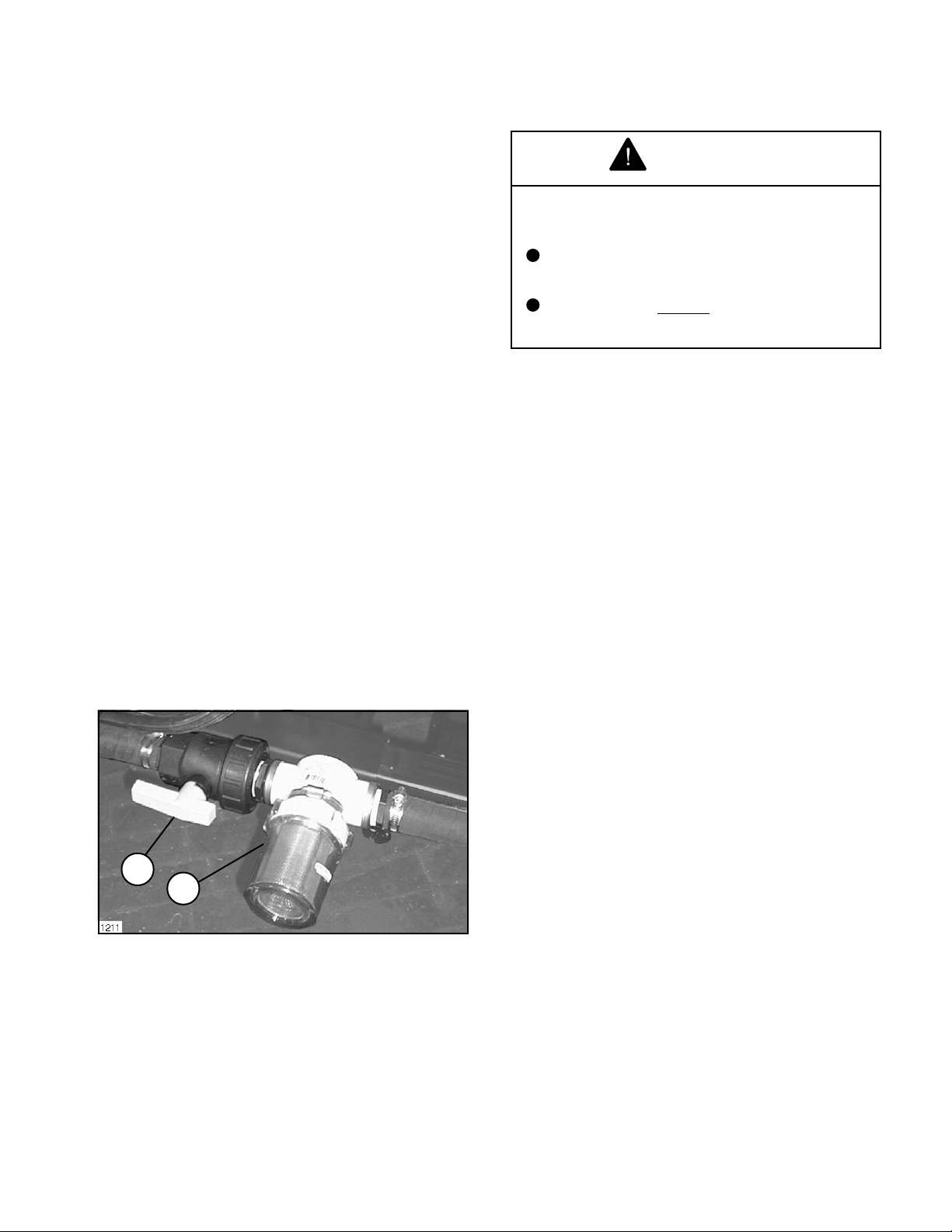
SUCTION STRAINER:
Turn off Suction Line Valve if Tank is full of spray
solution. Remove the cap and clean the strainer
screen after every 50 hours when using liquid
chemical, or after every use when spraying
wettable powders.
IMPORTANT: Do not operate the pump dry! Be
certain Suction Line Valve is opened when
spraying is resumed. Damage to Spray Pump
will result when operating the Sprayer with
Valve closed.
ROTATING PULLEYS AND BELTS CAN
CAUSE SERIOUS INJURY.
Keep hands, feet and clothing clear
while engine is running.
Stop engine
adjustment.
Keep Belt and Pulley free from any foreign material
which may cause slippage. If a belt slips, tighten
it.
Check the tension on a new drive Belt frequently
during the first day of operation and periodically
thereafter.
After every 200 hours of operation, check the
tension of all Belts. If a Belt shows signs of cracks
or fraying, install a new Belt.
before attempting any belt
1
2
FIG. 8
1. Suction Line Valve 2. Suction Strainer
(open)
17
Page 18
MAINTENANCE
41441 CENTRIFUGAL PUMP
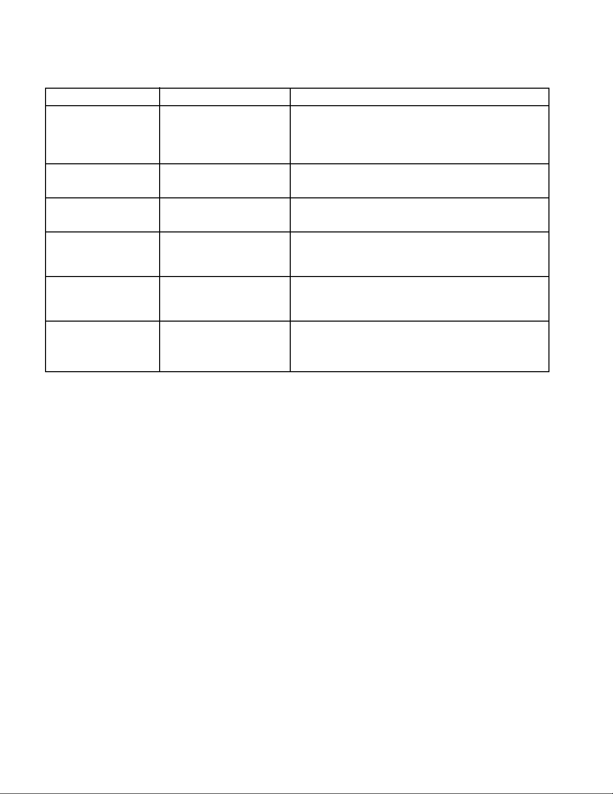
CENTRIFUGAL PUMP SEAL PROBLEM TROUBLESHOOTING
Trouble Probable Cause Remedy
1. Cracked or broken Seal ran dry and heated up. Check to insure seal chamber is full of liquid before
stationary seat (Ceramic) When liquid reached seal starting pump. On high temperature application
faces it was cooler, causing insure proper flushing at seal faces.
thermal cracks.
2. Carbon washer scored Dirty System. Have system cleaned and flushed.
grooved.
3. Carbon washer worn Seal improperly installed. Check installation instructions for proper assembly.
unevenly.
4. Rubber bellows of Did pump run dry or cavitate. Check to insure seal chamber is full of liquid before
seal are hard and brittle starting pump.
Rapid carbon wear.
5. Flexible bellows Seal improperly installed. Check installation instructions for proper assembly.
broken.
6. Seal wears out Check bearings for shaft end Replace bearings.
shaft. play. Check bearings for Replace shaft.
shaft radial movement.
Check shaft straitness.
18
Page 19
MAINTENANCE
41441 CENTRIFUGAL PUMP
Always flush pump with water, or neutralizing agent
before servicing.
Refer to the illustrated Parts List for part ordering
information.
Pump Housing Disassembly
In most cases, seal replacement requires
disassembly of only the pump half of the unit.
1. Remove the four casing cap screws with 9/16"
box end wrench. Tap pump casing on discharge
port with rubber hammer, if necessary, to break
loose from mounting flange. Check inside of pump
casing including suction port. If badly eroded (or
damaged), pump casing should be replaced.
Remove O-ring and discard. O-ring should always
be replaced.
2. Remove stationary seat and boot by prying out
with two small screwdrivers in manner similar to
impeller removal. (Caution: The seal will be
damaged by removal in this manner. A new seal
and rubber gasket MUST be used when pump is
reassembled.)
Clean-Up of Pump Housing
1. Using a circular bottle-type wire brush with air
or hand drill, clean the discharge port, suction port
and the sealing areas of the O-ring on the pump
casing and mounting flange.
2. After wire brush cleaning, it is recommended
that the pump casing and mounting flange be
further cleaned in a solvent tank to remove rust
and corrosion particles.
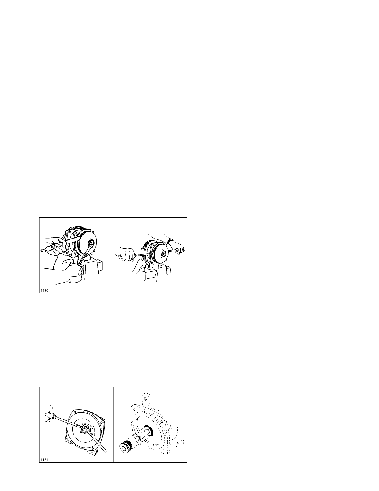
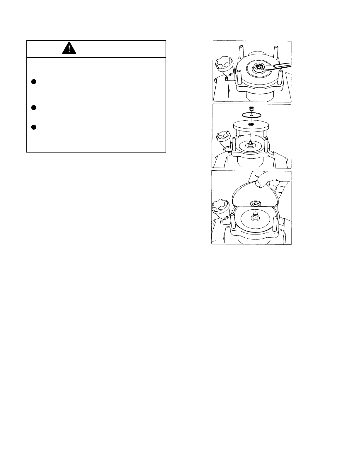
2. To remove the impeller nut, clamp the flange
in a vise and insert a large screwdriver or file (at
least 10" long) into impeller vanes to prevent
impeller from turning when loosening nut. Use a
5/8" box end or socket wrench to remove the
impeller nut by turning it counterclockwise. See
FIG. 9.
FIG. 9
3. Once nut is removed, place a screwdriver on
each side (FIG. 9) behind the impeller and pry
away from the mounting flange. Remove woodruff
key from the shaft. Remove O-ring from the
mounting flange.
Pump Seal Removal
1. Lightly lubricate shaft with mineral oil or
glycerin for easier removal of seal. Using two
screwdrivers positioned opposite each other, pry
the rotary portion of the seal from the shaft. See
FIG. 10.
Seal Replacement/Pump Housing
Reassembly
NOTE: Reassemble if drive end is not to be
repaired.
Be extremely careful with the new seal. Take
special care not to scratch the lapped sealing faces
of the rotary washer and stationary seat.
1. Lubricate seal cavity in mounting flange with
mineral oil or glycerin.
2. Install the stationary portion of the mechanical
seal by sliding over the shaft with the ceramic side
out.
IMPORTANT: Make sure both seal cavity and
seal are clean and lubricated. Never run the
sealing faces dry.
3. To seat the seal in the seal cavity, use a piece
of 3/4" PVC pipe 4" to 6" in length. Press it in firmly
and squarely.
4. To install the rotary portion of the mechanical
seal, place it over the shaft with the carbon side
facing in, and press until it bottoms out against
the stationary portion. Install rubber spacer. See
FIG. 10.
5. Insert key into shaft key slot. Place impeller
on shaft. Put impeller nut on shaft end using a
large screwdriver or file in the impeller vanes for
support, tighten impeller nut securely.
FIG. 10
6. Install O-ring on mounting flange. Replace
O-ring.
7. Place pump casing on mounting flange, insert
and tighten bolts evenly.
19
Page 20
SAFETY INSTRUCTIONS
41443 DIAPHRAGM PUMP
1. When the Diaphragm (high pressure) Pump
System is to be used:
WARNING
A. Check hoses for weak or worn condition
before each use. Make sure that all
connections are tight and secure.
B. Make sure there are no restrictions in the
hoses serving the Diaphragm Pump. Liquids
under high pressure are dangerous!
WARNING
Loss of control of the transport vehicle can
cause serious injury to operator or
bystanders.
Never use Spray Gun from operator's
seat while vehicle is in motion.
Always stop vehicle on level surface
and set parking brake before
dismounting to use Spray Gun.
WARNING
The highly pressurized discharge of spray
solution may cause a whipping action,
causing personal injury and/or property
damage.
Fluids under high pressure can penetrate the
human skin and can cause severe injury,
possibly resulting in amputation or death.
Hot liquids and chemicals can also
cause burns or injury.
DO NOT at any time place hand or any
other part of the body in front of spray
stream.
If any part of the body comes in contact
with the spray stream, immediately
consult a physician.
2. Before servicing or making any adjustments
to the Diaphragm Pump:
A. Release all pressure within the system;
shut off the engine and lift the relief valve lever
at the pump.
B. Drain all liquids from the system.
C. When replacing any parts, pipe, fittings,
accessories, hoses, etc., they must be rated
for the maximum pressure (600 PSI) of the
Diaphragm Pump.
Secure the Spray Gun and Hose before
starting the Pump.
20
Page 21
CONTROLS
41443 DIAPHRAGM PUMP
PRESSURE CONTROL UNIT: Controls the
operating pressure and flow of spray solution.
PUMP ENGAGEMENT LEVER: Engages and
disengages Diaphragm Pump.
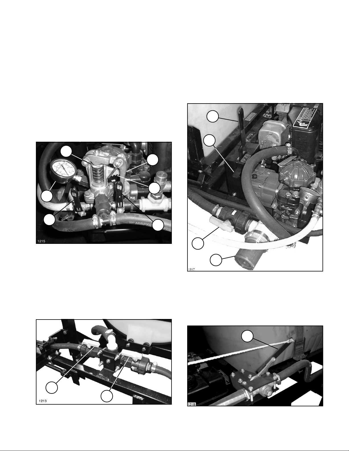
A. Spray Gun Valve: Opens and closes to
control the supply of spray solution to the Hand
Spray Gun. See FIG. 11.
B. Pressure Relief/Adjustment Valve:
Controls the operational pressure of the spray
system. Raise the lever to relieve the pressure
in the system. Hook loop into selected
Pressure Adjustment Notch and push the lever
down for the desired operating pressure.
C. Pressure Gauge: Indicates the operating
pressure of the sprayer system.
3
4
6
2
1
5
PUMP ENGAGEMENT RELEASE LEVER:
Releases the Pump Engagement Lever to allow
pump to be engaged.
SUCTION VALVE HANDLE: Opens and closes
the Suction Line Valve. Close during maintenance
to the Suction Line Strainer or Diaphragm Pump.
3
4
FIG. 11
1. Spray Gun Valve 4. Press. Relief/Adjustment
(Closed) Valve (in # four position)
2. Pressure Gauge 5. Optional Boom Valve
3. Fine Adj. Knob (Closed)
6. Pressure Adj. Notches
LEFT BOOM SHUTOFF VALVE HANDLE: Starts
or stops flow to left Boom.
RIGHT BOOM SHUTOFF VALVE HANDLE: Starts
or stops flow to right Boom.
1
2
FIG. 12
1. Left Boom Shutoff 2. Right Boom Shutoff
Valve (open) Valve (open)
1
2
FIG. 13
1. Suction Valve 3. Pump Engagement Lever
(Open) 4. Pump Engagement
2. Suction Strainer Release Lever
RATCHET VALVE HANDLE: Opens and closes
the Ratchet Valve, starting or stopping flow to
Booms.
1
FIG. 14
1. Ratchet Valve
21
Page 22
BEFORE SPRAYING
41443 DIAPHRAGM PUMP
INITIAL SYSTEM SET-UP FOR SPRAY GUN
USE:
1. Fill the Tank with clean, clear water. Do NOT
add chemical to the Tank until just before
beginning to spray.
2. OPEN the Suction Line Valve.
3. Lift the Pressure Relief/Adjustment Valve Lever
completely to relieve any pressure build-up in
system. Close the valve.
These pressures can be adjusted by using the fine
adjustment knob located on top of the relief valve
spring. The fine adjustment knob can be rotated
when the relief valve lever is in the up position.
6. When the adjustment is complete and you
have the hose line secured, to prevent any
whipping action, open the Spray Gun Valve to
begin spraying.
WARNING
4. Park vehicle on level surface and set the
parking brake. Move the Pump Engagement Lever
to the OFF position. See Fig. 13. Start the engine
as instructed in the ENGINE OPERATING
INSTRUCTIONS section.
5. Adjust the Diaphragm Pump to the desired
pressure as follows:
A. Clamping the Relief Valve Lever down with
the ball hook in number one position, the
pressure is about 100 PSI See Fig. 11.
B. In the number two position, the pressure
is about 250 PSI.
C. In the number three position, the pressure
is about 450 PSI.
D. In the number four position, the pressure
is about 550 PSI.
Fluids under high pressure can cause severe
injury.
NEVER USE DIAPHRAGM PUMP WHEN
SPRAYING WITH A HOSE AND/OR A
SPRAY GUN RATED AT LESS THAN 600
P.S.I.
INITIAL SYSTEM SET-UP FOR BOOM SPRAY
OPTION:
1. Adjust the Diaphragm Pump to the desired
pressure as described in Initial System Set-up for
use with Spray Gun.
NOTE: To use the standard light blue 95-9188
(1 GPM) Nozzles and all three Boom Sections,
you must have the Relief Valve Lever hooked
on the number four position and the engine
running at full RPM.
2. OPEN the Boom Valve.
22
Page 23
BEFORE SPRAYING
41443 DIAPHRAGM PUMP
FILLING THE SOLUTION TANK:
WARNING
CHEMICALS ARE HAZARDOUS AND CAN
CAUSE PERSONAL INJURY!
Carefully read the directions printed on
the chemical manufacturers labels
before handling chemicals. Instructions
on chemical manufacturers container
labels, regarding mixing proportions,
should be read and strictly followed.
Keep spray material from skin. If spray
material comes in contact with body,
wash it off immediately with clean water
and detergent.
Always wear goggles and other
protective equipment as recommended
by the Chemical Manufacturer.
IMPORTANT: Do not add chemical to Tank until
just before use. The concentrate should not be
poured into an empty Tank. Fill Tank at least one-
half full with clean, clear water, add chemical
concentrate and finish filling Tank with water.
Follow the chemical manufacturers
instructions for mixing spray solution to obtain
desired application rate.
FILL THE FRESH WATER WASH TANK
NOTE: Fill Fresh Water Wash Tank with clean
water only. Check to assure tank is full before
each operation.
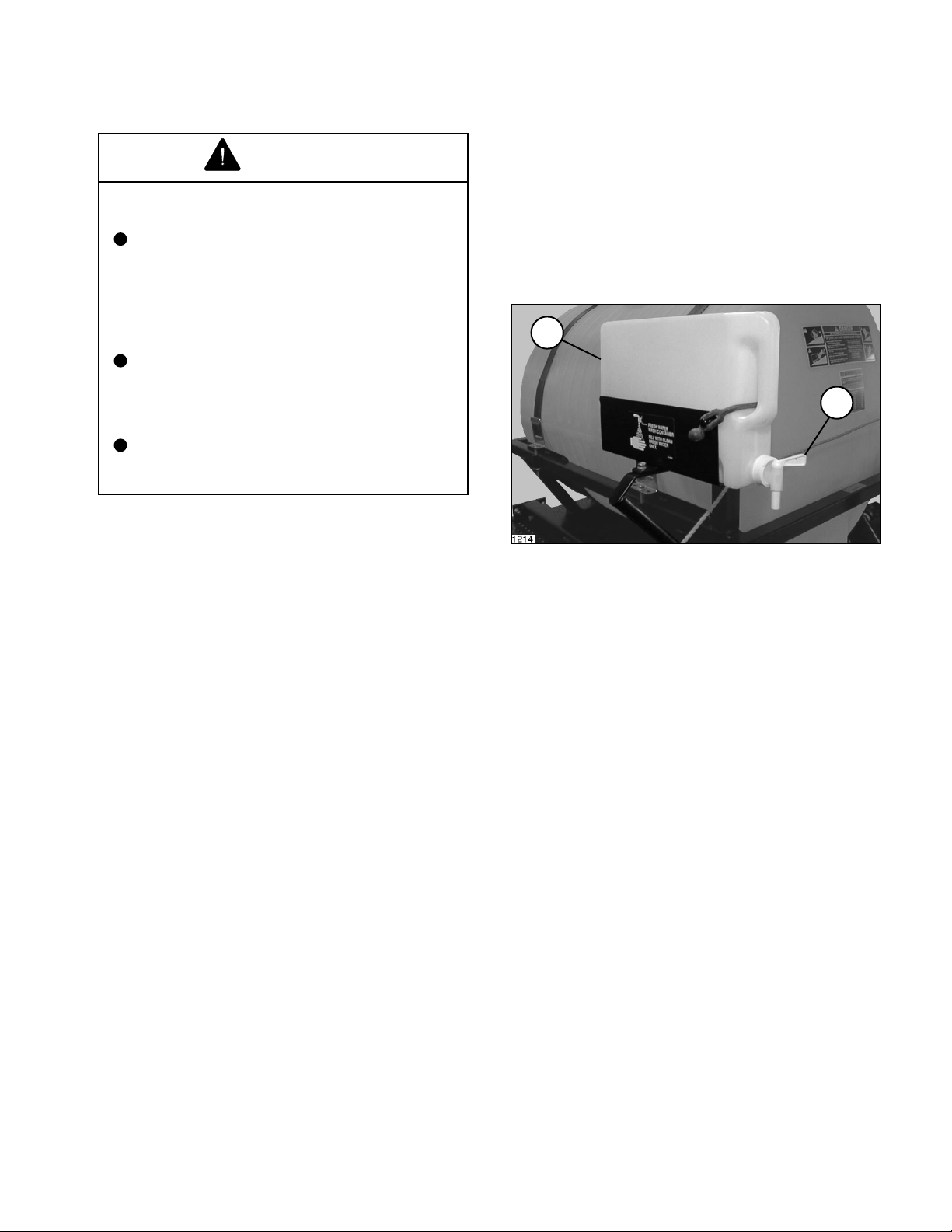
In case of chemical contact with skin or eyes, a
fresh water wash tank has been installed on the
Tank Saddle.
1. Turn Tank Spigot to on position. See FIG. 15.
1
2
FIG. 15
1. Fresh Water Wash Tank 2. Tank Spigot
2. Hold contaminated area directly under water
stream.
AFTER SPRAYING
41443 DIAPHRAGM PUMP
It is extremely important to carefully wash and
clean the Tank after every use.
Not only the Tank but the Pump, Hoses, Nozzles,
Screens, Filters, and the exterior of the Sprayer
also should be cleaned.
Flush Pump After Use
One of the most common causes for faulty pump
performance is "gumming" or corrosion inside the
pump. Flush the pump and entire system with a
solution that will chemically neutralize the liquid
pumped. Mix according to the chemical
manufacturer's directions. This will dissolve most
residue remaining in the pump, leaving the inside
of the pump clean for the next use.
A minimum of three 50 gallon rinses usually is
required for all components of the Sprayer. The
addition of a detergent cleaner may be advisable
in the initial washing. Directions for such an
addition, if required, are included on the chemical
container.
Cleaning of the Sprayer should be accomplished
in an area where there is no potential for the
chemicals to be washed off in surface water or to
enter subsurface drainage systems.
When Sprayer is not to be used for an extended
period, refer to the STORAGE section of this
Manual for the detailed instructions to prevent
damage to the components.
23
Page 24
MAINTENANCE
41443 DIAPHRAGM PUMP
WARNING
Fluids under high pressure can cause severe
injury.
Liquid is discharged from the Diaphragm
Pump under pressures that are high
enough to cause personal injury!
Before disconnecting any high pressure
components:
Shut engine off and lift relief valve level
at pump to relieve any build-up of
pressure.
DIAPHRAGM PUMP:
After every 500 hours of operation, change oil and
diaphragms.
1. Remove cap from oil sight tube, turn Pump
upside down and rotate the shaft until oil stops
flowing out.
2. Refill Pump with 30W oil; slowly pour oil into
sight tube while turning the Pump shaft. Turning
the shaft purges all the air out of the crankcase.
Always change oil when replacing diaphragms.
VALVE AND O-RING REPLACEMENT:
Occasionally debris can cause the valves to not
seat properly or damage the O-Rings. To check
for this problem follow these steps:
1. Remove the Pump manifold (See Parts List).
Use a 17 mm box wrench to remove manifold nuts.
With manifold removed, valves can readily be
removed and checked for debris or wear.
2. To replace valves or O-Rings, see your TORO
Dealer for the appropriate kits.
DIAPHRAGM REPLACEMENT:
1. Drain the oil from the Pump by removing cap
from oil sight tube and inverting the Pump. Rotate
the shaft to remove excess oil.
3. Use a 13 mm box wrench to remove the
diaphragm retaining bolt, support washer and
diaphragm.
4. To replace diaphragms, see your TORO dealer
for the appropriate repair kit.
5. Turn the crankshaft to bring the piston to its
downstroke and set the new diaphragm into the
sleeve groove. Install retaining washer and tighten
nut.
6. Replace the pulsation damper diaphragm by
first bleeding the air from the damper. Use a 13
mm box wrench to remove the bolts holding the
damper assembly together, then replace
diaphragm. Recharge pulsation damper, using
valve stem in head of Diaphragm Pump, to 20% of
operation pressure.
2. Remove the Pump manifold. Use a 17 mm
box wrench to remove manifold nuts.
24
7. Refill crankcase with 30W oil. Rotate the shaft
to distribute and fill to proper level.
Page 25
CONTROLS
41442 PTO PUMP
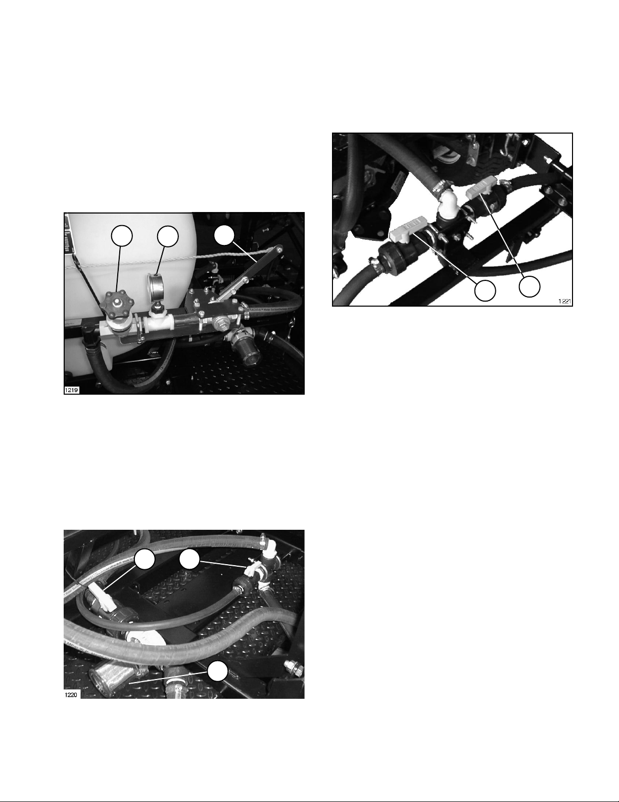
RATCHET VALVE HANDLE: Opens and closes
the Ratchet Valve, starting or stopping flow to
Booms.
PRESSURE ADJUST VALVE HANDLE: Controls
spray pressure. Turn clockwise to decrease
pressure and counterclockwise to increase
pressure.
PRESSURE GAUGE: Shows spray pressure when
Ratchet Valve is open. Shows deadhead pressure
when the Ratchet Valve is closed.
3
2
1
LEFT BOOM SHUTOFF VALVE HANDLE: Starts
or stops flow to left Boom.
RIGHT BOOM SHUTOFF VALVE HANDLE: Starts
or stops flow to right Boom.
1
FIG. 18
1. Left Boom Shutoff 2. Right Boom Shutoff
Valve (open) Valve (open)
2
FIG. 16
1. Ratchet Valve 3. Pressure Adjust Valve
Handle Handle
2. Pressure Gauge
AGITATOR VALVE HANDLE: Opens and closes
the Agitator Valve to activate, adjust or stop the
agitation of the spray solution in the Tank.
SUCTION VALVE HANDLE: Opens and closes
the Suction Line Valve. Close during maintenance
to the Suction Line Strainer or Centrifugal Pump.
1 2
3
FIG. 17
1. Suction Valve Handle 3. Suction Strainer
(open)
2. Agitator Valve Handle
(open)
25
Page 26
BEFORE SPRAYING
41442 PTO PUMP
INITIAL SYSTEM SET-UP:
1. Fill the Tank with clean, clear water and open
the Suction Line Valve.
1
IMPORTANT: The pump will be damaged if it is
activated before it is completely filled with
liquid. Be certain the suction line valve is open
and liquid has reached the pump.
2. Take the vehicle out of gear and set the parking
brake. Start the Vehicles engine and set throttle
to represent the desired spraying speed.
3. Engage PTO Drive.
4. Open Ratchet Valve to begin spraying water
from the booms.
5. Adjust the Pressure Adjust Valve to the desired
spray pressure.
NOTE: This entire procedure should be
repeated whenever changing operating
pressure, nozzles, speed, chemical, etc.
FILL THE FRESH WATER WASH TANK
NOTE: Fill Fresh Water Wash Tank with clean
water only. Check to assure tank is full before
each operation.
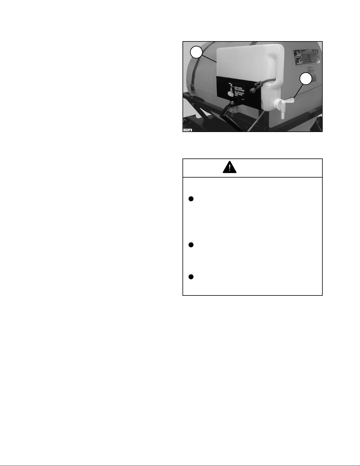
In case of chemical contact with skin or eyes, a
fresh water wash tank has been installed on the
Tank Saddle.
2
FIG. 19
1. Fresh Water Wash Tank 2. Tank Spigot
FILLING THE SOLUTION TANK:
WARNING
CHEMICALS ARE HAZARDOUS AND CAN
CAUSE PERSONAL INJURY!
Carefully read the directions printed on
the chemical manufacturers labels
before handling chemicals. Instructions
on chemical manufacturers container
labels, regarding mixing proportions,
should be read and strictly followed.
Keep spray material from skin. If spray
material comes in contact with body,
wash it off immediately with clean water
and detergent.
1. Turn Tank Spigot to on position. See FIG. 4.
2. Hold contaminated area directly under water
stream.
26
Always wear goggles and other
protective equipment as recommended
by the Chemical Manufacturer.
IMPORTANT: Do not add chemical to Tank until
just before use. The concentrate should not be
poured into an empty Tank. Fill Tank about one-
half full with clean, clear water, add chemical
concentrate and finish filling Tank with water.
Follow the chemical manufacturers instructions
for mixing spray solution to obtain desired
application rate.
Page 27
PREVENTIVE MAINTENANCE
41442 PTO PUMP
Preventative maintenance is most important to
assure long life of the Skid Sprayer. The following
maintenance procedures should be followed on a
regular basis:
It is extremely important to carefully wash and
clean the Tank after every use.
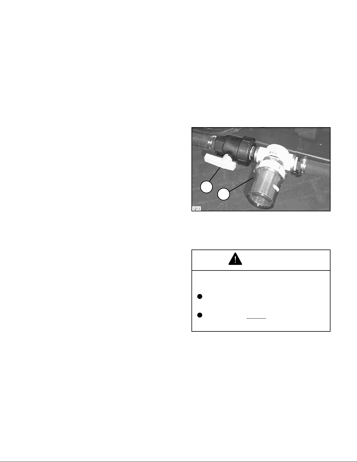
SUCTION STRAINER:
Turn off Suction Line Valve if Tank is full of spray
solution. Remove the cap and clean the strainer
screen after every 50 hours when using liquid
chemical, or after every use when spraying
wettable powders.
Not only the Tank but the Pump, Hoses, Nozzles,
Screens, Filters, and the exterior of the Sprayer
also should be cleaned.
Wash spray nozzles thoroughly with water. Blow
out orifice, clean and dry. If orifice remains
clogged, clean it with a soft bristled brush... never
use a metal object.
Check all of the nozzles frequently to spot any
inconsistencies in the spray pattern. Worn nozzle
orifices which allow a greater volume of spray
material to flow through the nozzle can cause an
expensive loss in chemical and/or turf damage.
Flush Pump After Use
One of the most common causes for faulty pump
performance is "gumming" or corrosion inside the
pump. Flush the pump and entire system with a
solution that will chemically neutralize the liquid
pumped. Mix according to the chemical
manufacturer's directions. This will dissolve most
residue remaining in the pump, leaving the inside
of the pump clean for the next use.
A minimum of three 50 gallon rinses usually is
required for all components of the Sprayer. The
addition of a detergent cleaner may be advisable
in the initial washing. Directions for such an
addition, if required, are included on the chemical
container.
Cleaning of the Sprayer should be accomplished
in an area where there is no potential for the
chemicals to be washed off in surface water or to
enter subsurface drainage systems.
IMPORTANT: Do not operate the pump dry! Be
certain Suction Line Valve is opened when
spraying is resumed. Damage to Spray Pump
will result when operating the Sprayer with Valve
closed.
1
2
FIG. 20
1. Suction Line Valve 2. Suction Strainer
(open)
BELT TENSION:
WARNING
ROTATING PULLEYS AND BELTS CAN
CAUSE SERIOUS INJURY.
Keep hands, feet and clothing clear
while engine is running.
Stop engine
adjustment.
before attempting any belt
When Sprayer is not to be used for an extended
period, refer to the STORAGE section of this
Manual for the detailed instructions to prevent
damage to the components.
Keep Belt and Pulley free from any foreign material
which may cause slippage. If a belt slips, tighten
it.
Check the tension on a new drive Belt frequently
during the first day of operation and periodically
thereafter.
After every 200 hours of operation, check the
tension of all Belts. If a Belt shows signs of cracks
or fraying, install a new Belt.
27
Page 28
MAINTENANCE
41442 PTO PUMP
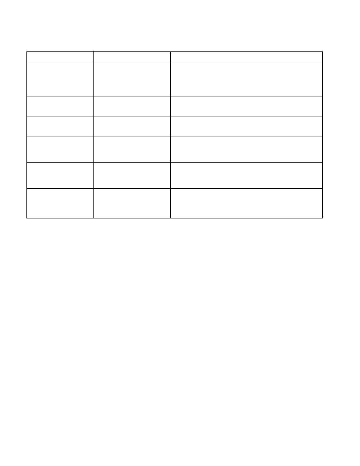
CENTRIFUGAL PUMP SEAL PROBLEM TROUBLESHOOTING
Trouble Probable Cause Remedy
1. Cracked or broken Seal ran dry and heated up. Check to insure seal chamber is full of liquid before
stationary seat (Ceramic) When liquid reached seal starting pump. On high temperature application
faces it was cooler, causing insure proper flushing at seal faces.
thermal cracks.
2. Carbon washer scored Dirty System. Have system cleaned and flushed.
grooved.
3. Carbon washer worn Seal improperly installed. Check installation instructions for proper assembly.
unevenly.
4. Rubber bellows of Did pump run dry or cavitate. Check to insure seal chamber is full of liquid before
seal are hard and brittle starting pump.
Rapid carbon wear.
5. Flexible bellows Seal improperly installed. Check installation instructions for proper assembly.
broken.
6. Seal wears out Check bearings for shaft end Replace bearings.
shaft. play. Check bearings for Replace shaft.
shaft radial movement.
Check shaft straitness.
28
Page 29
MAINTENANCE
41442 PTO PUMP
Always flush pump with water, or neutralizing agent
before servicing.
Refer to the illustrated Parts List for part ordering
information.
Pump Housing Disassembly
In most cases, seal replacement requires
disassembly of only the pump half of the unit.
1. Remove the four casing cap screws with 9/16"
box end wrench. Tap pump casing on discharge
port with rubber hammer, if necessary, to break
loose from mounting flange. Check inside of pump
casing including suction port. If badly eroded (or
damaged), pump casing should be replaced.
Remove O-ring and discard. O-ring should always
be replaced.
2. Remove stationary seat and boot by prying out
with two small screwdrivers in manner similar to
impeller removal. (Caution: The seal will be
damaged by removal in this manner. A new seal
and rubber gasket MUST be used when pump is
reassembled.)
Clean-Up of Pump Housing
1. Using a circular bottle-type wire brush with air
or hand drill, clean the discharge port, suction port
and the sealing areas of the O-ring on the pump
casing and mounting flange.
2. After wire brush cleaning, it is recommended
that the pump casing and mounting flange be
further cleaned in a solvent tank to remove rust
and corrosion particles.
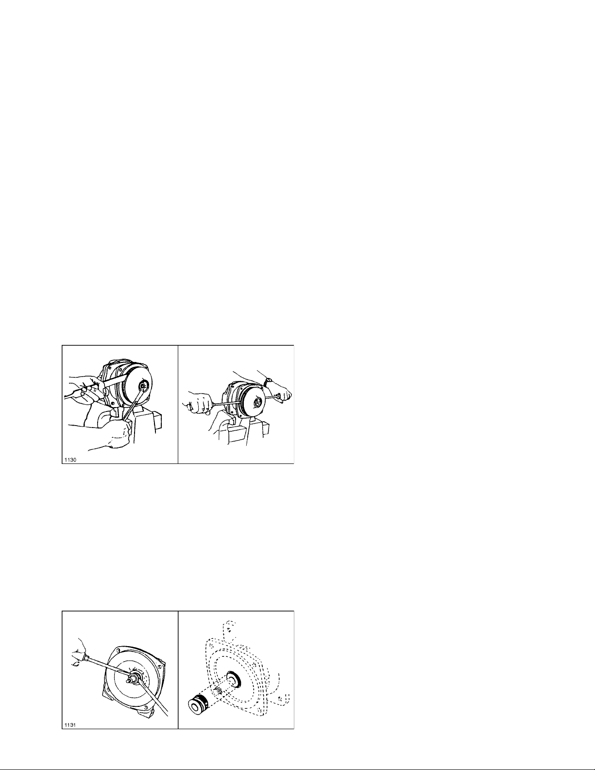
2. To remove the impeller nut, clamp the flange
in a vise and insert a large screwdriver or file (at
least 10" long) into impeller vanes to prevent
impeller from turning when loosening nut. Use a
5/8" box end or socket wrench to remove the
impeller nut by turning it counterclockwise. See
FIG. 21.
FIG. 21
3. Once nut is removed, place a screwdriver on
each side (FIG. 21) behind the impeller and pry
away from the mounting flange. Remove woodruff
key from the shaft. Remove O-ring from the
mounting flange.
Pump Seal Removal
1. Lightly lubricate shaft with mineral oil or
glycerin for easier removal of seal. Using two
screwdrivers positioned opposite each other, pry
the rotary portion of the seal from the shaft. See
FIG. 22.
Seal Replacement/Pump Housing
Reassembly
NOTE: Reassemble if drive end is not to be
repaired.
Be extremely careful with the new seal. Take
special care not to scratch the lapped sealing faces
of the rotary washer and stationary seat.
1. Lubricate seal cavity in mounting flange with
mineral oil or glycerin.
2. Install the stationary portion of the mechanical
seal by sliding over the shaft with the ceramic side
out.
IMPORTANT: Make sure both seal cavity and
seal are clean and lubricated. Never run the
sealing faces dry.
3. To seat the seal in the seal cavity, use a piece
of 3/4" PVC pipe 4" to 6" in length. Press it in firmly
and squarely.
4. To install the rotary portion of the mechanical
seal, place it over the shaft with the carbon side
facing in, and press until it bottoms out against
the stationary portion. Install rubber spacer. See
FIG. 22.
5. Insert key into shaft key slot. Place impeller
on shaft. Put impeller nut on shaft end using a
large screwdriver or file in the impeller vanes for
support, tighten impeller nut securely.
FIG. 22
6. Install O-ring on mounting flange. Replace
O-ring.
7. Place pump casing on mounting flange, insert
and tighten bolts evenly.
29
Page 30

Helping you put quality into
®
30
Page 31

Helping you put quality into
®
31
Page 32

The Toro Commercial Products Two Year Limited Warranty
The Toro Company warrants your 1996 or newer Toro Commercial Product (Product) purchased after January
1, 1997, to be free from defects in materials or workmanship for the period of time listed below. Where a
warrantable condition exists, Toro will repair the Product at no cost to you including diagnosis, labor , parts, and
transportation. This warranty begins on the date the Product is delivered to the original retail purchaser.
Warranty Duration: Two years or 1500 operational hours*, whichever occurs first.
*Product equipped with hour meter
Owner Responsibilities:
As the Product owner, you are responsible for required
maintenance and adjustments stated in your Owners
Manual. Failure to preform required maintenance and
adjustments can be grounds for disallowing a warranty
claim.
Instructions for Obtaining Warranty Service:
You are responsible for notifying the Commercial Products
Distributor or Authorized Commercial Products Dealer from
whom you purchased the Product as soon as you believe a
warrantable condition exists.
If you need help locating a Commercial Products Distributor
or Authorized Dealer, or if you have questions regarding
your warranty rights or responsibilities, you may contact us
at:
TORO Commercial Products Service Department
8111 Lyndale Avenue South
Minneapolis, MN 55420-1196
Telephone: (612) 888-8801
Facsimile: (612) 887-8258
E-Mail: [email protected]
Maintenance Parts:
Parts scheduled for replacement as required maintenance
(Maintenance Parts), are warranted for the period of time
up to the scheduled replacement time for that part.
Items/Conditions Not Covered:
Not all product failures or malfunctions that occur during the
warranty period are defects in material or workmanship. The
items / conditions listed below are not covered by this
warranty:
• This warranty does not apply to parts subject to
consumption through use unless found to be defective.
Examples of parts which are consumed, or used up,
during normal Product operation include, but are not
limited to, blades, reels, bedknives, tines, spark plugs,
castor wheels, tires, filters, belts, etc.
• This warranty does not apply to failures caused by
outside influence. Items considered to be outside
influence include, but are not limited to, weather, storage
practices, contamination, use of unapproved coolants,
lubricants, additives, or chemicals, etc.
• This warranty does not apply to normal wear and tear
items. Normal Wear and Tear includes, but is not
limited to, damage to seats due to wear or abrasion,
worn painted surfaces, scratcheddecals or windows, etc.
Other Legal Disclaimers:
The above remedy of product defects through repair by an
authorized distributor or dealer is the purchasers sole
remedy for any defect. This warranty gives you specific legal
rights, and you may also have other rights which vary from
state to state.
Except for the Emissions warranty referenced below, If
applicable, there is no other express warranty. All
implied warranties of merchantability and fitness for use
are limited to the duration of the express warranty.
Some states do not allow limitations on how long an implied
warranty lasts, so the above limitations may not apply to you.
The Toro Company is not liable for indirect, incidental or
consequential damages in connection with the use of the
Product, including any cost or expense of providing
substitute Product or service during periods of malfunc-
tion or non-use.
• Product failures which result from the use of non-Toro
replacement parts, or from installation and use of add-on,
modified, or unapproved accessories are not covered.
• Product failures which result from failure to perform
required maintenance and/or adjustments are not
covered.
• Product failures which result from operating the Product
in an abusive, negligent, or reckless manner are not
covered.
Some states do not allow the exclusion of incidental or
consequential damages, so the above exclusion may not
apply to you.
Note to California residents: The Emissions Control
System on your Product may be covered by a separate
warranty meeting requirements established by the U.S.
Environmental Protection Agency (EPA), or the California Air
Resources Board (CARB). The hour limitations set forth
above do not apply to the Emissions Control System
Warranty. Refer to the California Emission Control Warranty
Statement printed in your Owners Manual or contained in
the engine manufacturers documentation for details.
 Loading...