

Page 1
FormNo.3377-127RevA
Multi-Pro
ModelNo.41199—SerialNo.313000001andUp
®
1200TurfSprayer
Registeratwww.T oro.com.
OriginalInstructions(EN)
*3377-127*A
Page 2
TheMulti-Pro®turfsprayerisadedicatedturfspray
G002182
1
applicationvehicleandisintendedtobeusedbyprofessional,
hiredoperatorsincommercialapplications.Itisprimarily
designedforsprayingonwell-maintainedlawnsinparks,golf
courses,sportselds,andoncommercialgrounds.
ThisproductcomplieswithallrelevantEuropeandirectives,
fordetailspleaseseetheseparateproductspecicDeclaration
ofConformity(DOC)sheet.
WARNING
CALIFORNIA
Proposition65Warning
Theengineexhaustfromthisproduct
containschemicalsknowntotheStateof
Californiatocausecancer,birthdefects,
orotherreproductiveharm.
Figure1
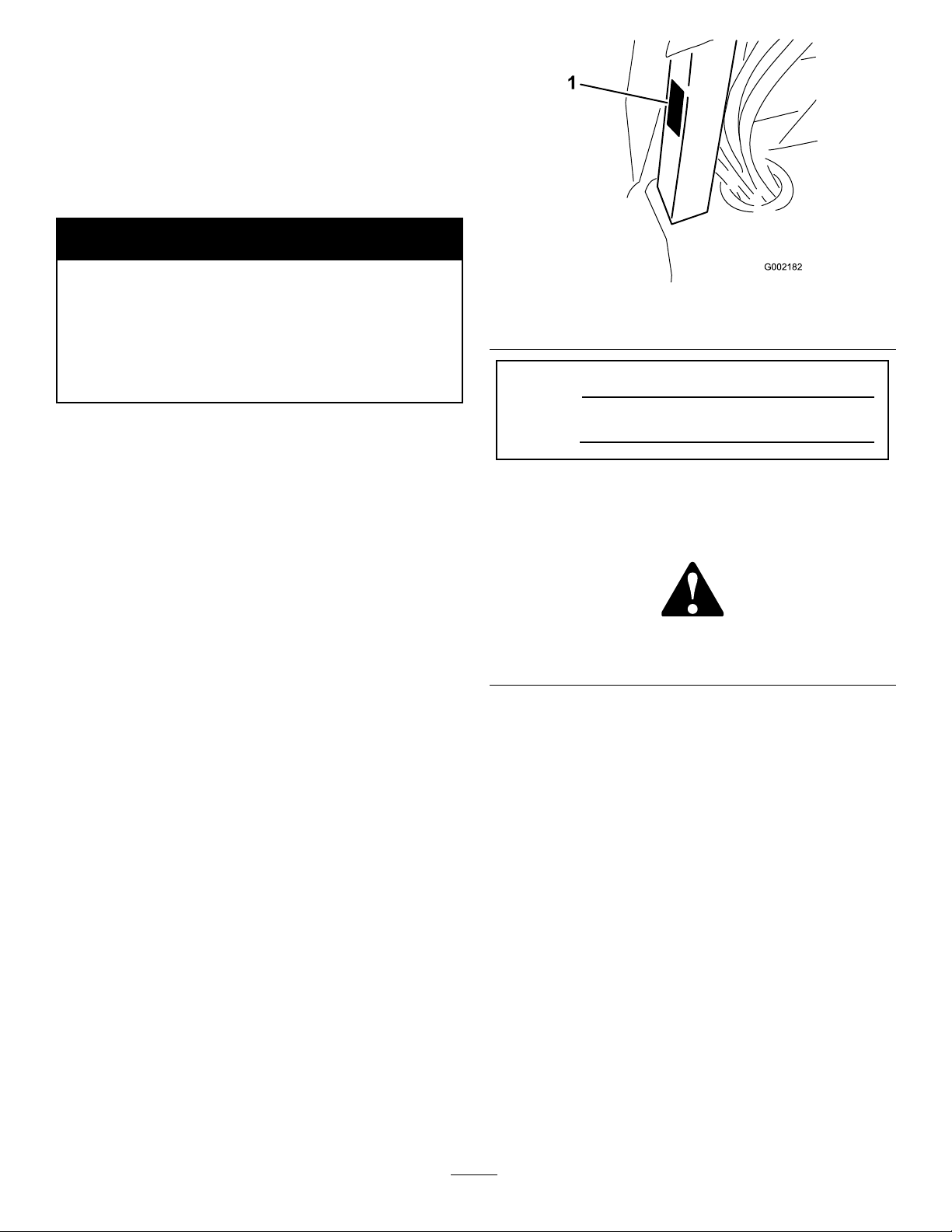
1.Locationofthemodelandserialnumbers
ModelNo.
Important:Thisengineisnotequippedwithaspark
arrestermufer.ItisaviolationofCaliforniaPublic
ResourceCodeSection4442touseoroperatetheengine
onanyforest-covered,brush-covered,orgrass-covered
land.Otherstatesorfederalareasmayhavesimilarlaws.
ThissparkignitionsystemcomplieswithCanadianICES-002.
Theenclosed
informationregardingtheUSEnvironmentalProtection
Agency(EPA)andtheCaliforniaEmissionControl
Regulationofemissionsystems,maintenance,and
warranty.Replacementsmaybeorderedthroughthe
enginemanufacturer.
Engine Owner's Man ual
issuppliedfor
Introduction
Readthismanualcarefullytolearnhowtooperateand
maintainyourproductproperly.Theinformationinthis
manualcanhelpyouandothersavoidinjuryandproduct
damage.AlthoughT orodesignsandproducessafeproducts,
youareresponsibleforoperatingtheproductproperlyand
safely.Y oumaycontactTorodirectlyatwww.Toro.comfor
productandaccessoryinformation,helpndingadealer,or
toregisteryourproduct.
Wheneveryouneedservice,genuineT oroparts,oradditional
information,contactanAuthorizedServiceDealerorToro
CustomerServiceandhavethemodelandserialnumbersof
yourproductready.
modelandserialnumbersontheproduct.
Figure1illustratesthelocationofthe
SerialNo.
Thismanualidentiespotentialhazardsandhassafety
messagesidentiedbythesafetyalertsymbol(Figure2),
whichsignalsahazardthatmaycauseseriousinjuryordeath
ifyoudonotfollowtherecommendedprecautions.
Figure2
1.Safetyalertsymbol.
Thismanualusestwootherwordstohighlightinformation.
Importantcallsattentiontospecialmechanicalinformation
andNoteemphasizesgeneralinformationworthyofspecial
attention.
Contents
Introduction..................................................................2
Safety...........................................................................4
SafeOperatingPractices...........................................4
ChemicalSafety.......................................................4
BeforeOperating....................................................4
WhileOperating......................................................5
Maintenance...........................................................6
SoundPower..........................................................7
SoundPressure.......................................................7
Hand-ArmVibration...............................................7
WholeBodyVibration.............................................7
SafetyandInstructionalDecals.................................8
Setup...........................................................................13
1InstallingtheAnti-siphonFillReceptacle.................13
2InstallingtheSprayProMonitor.............................14
©2012—TheT oro®Company
8111LyndaleAvenueSouth
Bloomington,MN55420
Contactusatwww.Toro.com.
2
PrintedintheUSA.
AllRightsReserved
Page 3

3CheckingtheBoomHingeSprings.........................15
4AdjustingtheBoomstoLevel................................16
5CompletingtheSetup:Learningmoreaboutyour
product..............................................................16
ProductOverview.........................................................17
Controls...............................................................18
Specications........................................................23
Attachments/Accessories........................................23
Operation....................................................................24
ThinkSafetyFirst...................................................24
BeforeDrivingtheSprayerfortheFirst
Time.................................................................24
Pre-StartingChecks................................................25
DrivingtheSprayer.................................................25
NewSprayerBreak-In.............................................26
OperatingtheSprayer.............................................26
FillingtheFreshWaterTank....................................26
FillingtheSprayTank..............................................27
OperatingtheBooms..............................................27
Spraying................................................................28
SprayingTips.........................................................28
CleaningtheSprayer...............................................28
CalibratingtheSprayProMonitor.............................31
CalibratingtheBoomBypassValves..........................33
Pump....................................................................33
TransportingtheSprayer.........................................34
TowingtheSprayer.................................................34
Maintenance.................................................................35
RecommendedMaintenanceSchedule(s)......................35
DailyMaintenanceChecklist....................................36
NotationforAreasofConcern.................................37
PremaintenanceProcedures........................................38
JackingtheSprayer.................................................38
Lubrication...............................................................38
GreasingtheSprayer...............................................38
GreasingtheBoomHinges......................................40
GreasingtheActuatorRodBearings..........................40
EngineMaintenance..................................................42
CheckingtheAirIntakeScreen.................................42
ServicingtheAirCleaner.........................................42
ServicingtheEngineOil..........................................43
ChangingtheSparkPlugs........................................44
FuelSystemMaintenance...........................................45
ReplacingtheFuelFilter..........................................45
DrainingtheFuelTank...........................................45
ElectricalSystemMaintenance....................................46
ReplacingtheFuses................................................46
ServicingtheBattery...............................................46
DriveSystemMaintenance.........................................49
InspectingtheWheels/Tires....................................49
AdjustingtheFrontWheelToe-In............................49
BrakeMaintenance....................................................50
CheckingtheBrakeFluid.........................................50
InspectingtheBrakes..............................................50
AdjustingtheParkingBrake.....................................50
BeltMaintenance......................................................51
ServicingtheDriveBelt...........................................51
AdjustingtheSteeringPumpBelt..............................51
HydraulicSystemMaintenance....................................52
CheckingtheTransaxle/HydraulicFluid....................52
ChangingTransaxle/HydraulicFluid.........................52
ReplacingtheHydraulicFilter..................................53
SpraySystemMaintenance..........................................53
InspectingtheHoses..............................................53
PumpMaintenance.................................................54
AdjustingtheBoomActuator...................................54
EmergencyManualOperationoftheBoom
Actuators...........................................................55
InspectingtheNylonPivotBushings.........................55
Cleaning...................................................................56
CleaningtheFlowmeter..........................................56
CleaningtheSuctionStrainer...................................57
Storage........................................................................57
Troubleshooting...........................................................59
Schematics...................................................................63
3
Page 4

Safety
ChemicalSafety
Improperuseormaintenancebytheoperatororownercan
resultininjury.Toreducethepotentialforinjury,comply
withthesesafetyinstructionsandalwayspayattentiontothe
safetyalertsymbol,whichmeansCAUTION,W ARNING,
orDANGER-personalsafetyinstruction.Failuretocomply
withtheinstructionmayresultinpersonalinjuryordeath.
Supervisors,operators,andservicepersonsshouldbefamiliar
withthefollowingstandardsandpublications:(Thematerial
maybeobtainedfromtheaddressshown).
•FlammableandCombustibleLiquidsCode:
ANSI/NFPA30
•NationalFireProtectionAssociation:
ANSI/NFPA#505;PoweredIndustrialTrucks
NationalFirePreventionAssociation
BarrymarchPark
Quincy,Massachusetts02269U.S.A.
•SAEJ2258LightUtilityVehiclesSocietyof
AutomotiveEngineers
SAEWorldHeadquarters400CommonwealthDrive
Warrendale,PA15096-0001
•ANSI/UL558;InternalCombustion
EnginePoweredIndustrialTrucks
AmericanNationalStandardsInstitute,Inc.
1430BroadwayNewYork,NewYork10018U .S.A.
or
UnderwritersLaboratories
333PngstenRoad
Northbrook,Illinois60062U.S.A.
SafeOperatingPractices
WARNING
Thesprayerisanoff-highwayvehicleonlyandis
notdesigned,equipped,ormanufacturedforuseon
publicstreets,roads,orhighways.
Supervisor'sResponsibilities
•Makesurethatoperatorsarethoroughlytrainedand
familiarwiththeOperator'sManual,EngineManual,andall
labelsonthesprayer.
•Establishyourownspecialproceduresandworkrules
forunusualoperatingconditions(e.g.slopestoosteep
forsprayeroperation).
WARNING
Chemical substances used in the spray system may
be hazardous and to xic to y ou, bystander s, animals,
plants, soils or other pr oper ty .
•Carefullyreadandfollowthechemical
warninglabelsandMaterialSafetyData
Sheets(MSDS)forallchemicalsusedand
protectyourselfaccordingtothechemical
manufacturer'srecommendations.Forexample,
useappropriatePersonalProtectiveEquipment
(PPE)includingfaceandeyeprotection,gloves,
orotherequipmenttoguardagainstpersonal
contactwiththechemical.
•Keepinmindthattheremaybemorethanone
chemicalusedandinformationoneachshould
beassessed.
R efuse to operate or w or k on the spray er if this
•
inf or mation is not a v aila ble!
•Beforeworkingonaspraysystemmakesurethe
systemhasbeentriplerinsedandneutralized
accordingtotherecommendationsofthe
chemicalmanufacturer(s).
•Verifythereisanadequatesupplyofcleanwater
andsoapnearby,andimmediatelywashoffany
chemicalsthatcontactyou.
•Obtainpropertrainingbeforeusingorhandling
chemicals.
•Usethecorrectchemicalforthejob.
•Followthechemicalmanufacturer'sinstructionsforthe
safeapplicationofthechemical.
•Handlechemicalsinawellventilatedarea.
•Weargogglesandotherprotectiveequipmentas
instructedbythechemicalmanufacturer.Ensurethatas
littleskinaspossibleisexposedwhileusingchemicals.
•Havecleanwateravailableespeciallywhenllingthe
spraytank.
•Donoteat,drink,orsmokewhileworkingwithchemicals.
•Alwayswashyourhandsandotherexposedareasassoon
aspossibleafternishingthework.
•Properlydisposeofunusedchemicalsandchemical
containersasinstructedbythechemicalmanufacturer
andyourlocalcodes.
•Chemicalsandfumesinthetanksaredangerous;never
enterthetankorplaceyourheadoverorintheopening.
BeforeOperating
•Operatethemachineonlyafterreadingandunderstanding
thecontentsofthismanual.
4
Page 5

•Neverallowchildrentooperatethesprayer.
•Neverallowotheradultstooperatethesprayerwithout
rstreadingandunderstandingtheOperator'sManual.
Onlytrainedandauthorizedpersonsshouldoperatethis
sprayer.Makesurethatalloperatorsarephysicallyand
mentallycapableofoperatingthesprayer.
•Thissprayerisdesignedtocarryonlyyou,theoperator.
Nevercarryanypassengersonthesprayer.
•Neveroperatethesprayerwhenundertheinuence
ofdrugsoralcohol.Evenprescriptiondrugsandcold
medicinescancausedrowsiness.
•Donotdrivethesprayerwhenyouaretired.Besureto
takeoccasionalbreaks.Itisveryimportantthatyoustay
alertatalltimes.
•Becomefamiliarwiththecontrolsandknowhowtostop
theenginequickly.
•Keepallshields,safetydevices,anddecalsinplace.Ifa
shield,safetydevice,ordecalismalfunctioning,illegible,
ordamaged,repairorreplaceitbeforeoperatingthe
machine.
•Alwayswearsubstantialshoes.Donotoperatethe
machinewhilewearingsandals,tennisshoes,orsneakers.
Donotwearloosettingclothingorjewelrywhichcould
getcaughtinmovingpartsandcausepersonalinjury.
•Wearingsafetyglasses,safetyshoes,longpants,anda
helmetisadvisableandrequiredbysomelocalsafetyand
insuranceregulations.
•Avoiddrivingwhenitisdark,especiallyinunfamiliar
areas.Ifyoumustdrivewhenitisdark,besuretodrive
cautiously,usetheheadlights,andevenconsideradding
additionallights.
•Beextremelycarefulwhenoperatingaroundpeople.
Alwaysbeawareofwherebystandersmightbeandkeep
themawayfromtheworkarea.
•Beforeoperatingthesprayer,alwayscheckthedesignated
areasofthesprayerthatarestatedinthePre-Starting
ChecksintheOperationsection.Ifthemachinedoes
notfunctioncorrectlyorisdamagedinanyway ,donot
usethesprayer.Makesurethattheproblemiscorrected
beforethesprayerorattachmentisoperated.
•Ensurethatalluidlineconnectorsaretightandallhoses
areingoodconditionbeforeapplyingpressuretothe
system.
•Sincegasolineishighlyammable,handleitcarefully.
–Useanapprovedgasolinecontainer.
–Donotremovethecapfromthefueltankwhenthe
engineishotorrunning.
–Donotsmokewhilehandlinggasoline.
–Fillthefueltankoutdoors,andllittoabout1inch
(25mm)belowthetopofthetank(thebottomofthe
llerneck).Donotoverllit.
–Wipeupanyspilledgasoline.
WhileOperating
WARNING
Engineexhaustcontainscarbonmonoxide,which
isanodorless,deadlypoisonthatcankillyou.
Donotrunengineindoorsorinanenclosedarea.
•Theoperatorshouldremainseatedwheneverthesprayer
isinmotion.Theoperatorshouldkeepbothhandson
thesteeringwheelwheneverpossible.Keepyourarms
andlegswithinthesprayerbodyatalltimes.
•Alwayswatchoutforandavoidlowoverhangssuchas
treelimbs,doorjambs,andoverheadwalkways.Make
surethereisenoughroomoverheadtoeasilyclearthe
sprayerandyourhead.
•Failuretooperatethesprayersafelymayresultinan
accident,tipoverofthesprayer,andseriousinjuryor
death.Drivecarefully.Topreventtippingorlossof
control:
–Useextremecaution,reducespeed,andmaintain
asafedistancearoundsandtraps,ditches,creeks,
ramps,unfamiliarareas,oranyareasthathaveabrupt
changesingroundconditionsorelevation.
–Watchforholesorotherhiddenhazards.
–Useextracautionwhenoperatingthesprayeronwet
surfaces,inadverseweatherconditions,athigher
speeds,orwithafullload.Stoppingtimeanddistance
willincreasewithafullload.
–Avoidsuddenstopsandstarts.Donotgofrom
reversetoforwardorforwardtoreversewithoutrst
comingtoacompletestop.
–Slowdownbeforeturning.Donotattemptsharp
turnsorabruptmaneuversorotherunsafedriving
actionsthatmaycausealossofsprayercontrol.
–Beforebackingup,looktotherearandensurethat
nooneisbehindyou.Backupslowly.
–Watchoutfortrafcwhenyouarenearorcrossing
roads.Alwaysyieldtherightofwaytopedestrians
andothervehicles.Thissprayerisnotdesignedfor
useonstreetsorhighways.Alwayssignalyourturns
orstopearlyenoughsothatotherpeopleknowwhat
youplantodo.Obeyalltrafcrulesandregulations.
–Theelectricalandexhaustsystemsofthesprayercan
producesparkscapableofignitingexplosivematerials.
Neveroperatethesprayerinornearanareawhere
thereisdustorfumesintheairwhichareexplosive.
–Ifyouareeverunsureaboutsafeoperation,stop
workandaskyoursupervisor.
•Donottouchtheengineormuferwhiletheengineis
runningorsoonafterithasstopped.Theseareasmaybe
hotenoughtocauseburns.
5
Page 6

•Ifthemachineevervibratesabnormally,stopimmediately,
waitforallmotiontostop,andinspectthesprayerfor
damage.Repairalldamagebeforeresumingoperation.
•Beforegettingoffoftheseat:
1.Stopthemovementofthemachine.
2.PlacetherangeselectorinNeutralandsetthe
parkingbrake.
3.TurntheignitionkeytoOff.
4.Removetheignitionkey .
Important:Donotparkthemachineonan
incline.
•Lightningcancausesevereinjuryordeath.Iflightning
isseenorthunderisheardinthearea,donotoperate
themachine;seekshelter.
onlevelground.Ifthesprayermustbestopped,avoid
suddenspeedchanges,whichmayinitiatetippingor
rollingofthesprayer.Donotslamonthebrakes
whenrollingbackward,asthismaycausethesprayerto
overturn.
•Usetheseatbeltwhenoperatingthemachineandbe
certainthatitcanbereleasedquicklyintheeventofan
emergency.
•Donotremoveoraltertherolloverprotectionsystem
(ROPS).
•Reducespeedandloadwhenoperatingonroughterrain,
unevenground,andnearcurbs,holes,andothersudden
changesinterrain.Loadsmayshift,causingthesprayer
tobecomeunstable.
WARNING
Braking
•Slowdownbeforeyouapproachanobstacle.Thisgives
youextratimetostoporturnaway .Hittinganobstacle
candamagethesprayeranditscontents.Moreimportant,
itcaninjureyou.
•GrossVehicleWeight(GVW)hasamajorimpactonyour
abilitytostopand/orturn.Heavyloadsandattachments
makeasprayerhardertostoporturn.Theheavierthe
load,thelongerittakestostop.
•Turfandpavementaremuchmoreslipperywhenthey
arewet.Itcantake2to4timesaslongtostoponwet
surfacesasondrysurfaces.Ifyoudrivethroughstanding
waterdeepenoughtogetthebrakeswet,theywillnot
workwelluntiltheyaredry.Afterdrivingthroughwater,
youshouldtestthebrakestomakesuretheywork
properly.Iftheydonot,driveslowlywhileputtinglight
pressureonthebrakepedal.Thiswilldrythebrakesout.
OperatingonHillsandRoughTerrain
Operatingthesprayeronahillmaycausetippingorrolling
ofthesprayer,ortheenginemaystallandyoucouldlose
headwayonthehill.Thiscouldresultinpersonalinjury.
•Donotacceleratequicklyorslamonthebrakeswhen
backingdownahill,especiallywithaload.
•Neverdriveacrossasteephill;alwaysdrivestraightupor
downorgoaroundthehill.
•Iftheenginestallsoryoubegintoloseheadwaywhile
climbingahill,graduallyapplythebrakesandslowlyback
straightdownthehill.
•Turningwhiletravelingupordownhillscanbe
dangerous.Ifyouhavetoturnwhileonahill,doitslowly
andcautiously.Nevermakesharporfastturns.
•Heavyloadsaffectstability.Reducetheweightoftheload
andyourspeedwhenoperatingonhills.
•Avoidstoppingonhills,especiallywithaload.Stopping
whilegoingdownahillwilltakelongerthanstopping
Suddenchangesinterrainmaycauseabrupt
steeringwheelmovement,possiblyresultingin
handandarminjuries.
•Reduceyourspeedwhenoperatingonroughterrainand
nearcurbs.
•Gripthesteeringwheellooselyaroundtheperimeter.
Keepyourhandsclearofthesteeringwheelspokes.
Loading
Theweightofthecargocanchangethesprayercenterof
gravityandsprayerhandling.Toavoidlossofcontroland
personalinjury,followtheseguidelines:
•Reducetheweightoftheloadwhenoperatingonhills
androughterraintoavoidtippingoroverturningofthe
sprayer.
•Liquidloadscanshift.Thisshiftinghappensmostoften
whileturning,goingupordownhills,suddenlychanging
speeds,orwhiledrivingoverroughsurfaces.Shifting
loadscancausethesprayertotipover.
•Whenoperatingwithaheavyload,reduceyourspeedand
allowforsufcientbrakingdistance.Donotsuddenly
applythebrakes.Useextracautiononslopes.
•Beawarethatheavyloadsincreaseyourstoppingdistance
andreduceyourabilitytoturnquicklywithouttipping
over.
Maintenance
•Onlypermitqualiedandauthorizedpersonnelto
maintain,repair,adjust,orinspectthesprayer.
•Beforeservicingormakingadjustmentstothemachine,
stoptheengine,settheparkingbrake,andremovethekey
fromtheignitiontopreventsomeonefromaccidentally
startingtheengine.
•Tomakesurethattheentiremachineisingoodcondition,
keepallnuts,bolts,andscrewsproperlytightened.
6
Page 7

•Toreducethepotentialforre,keeptheengineareafree
ofexcessivegrease,grass,leaves,andaccumulationofdirt.
•Neveruseanopenametocheckthelevelorleakageof
fuelorbatteryelectrolyte.
•Iftheenginemustberunningtoperformamaintenance
adjustment,keepyourhands,feet,clothing,andanyparts
ofyourbodyawayfromtheengineandanymovingparts.
Keepeveryoneaway .
•Donotuseopenpansoffuelorammablecleaning
uidswhencleaningparts.
•Donotadjustthegroundspeedgovernor.Toensure
safetyandaccuracy,haveanAuthorizedToroDistributor
checkthegroundspeed.
•Keepyourbodyandhandsawayfrompinholeleaksor
nozzlesthatejecthighpressureuid.Usecardboardor
papertondleaks.Fluidescapingunderpressurecan
penetrateskinandcauseinjuryrequiringsurgerywithina
fewhoursbyaqualiedsurgeonorgangrenemayresult.
•Ifmajorrepairsareeverneededorassistanceisrequired,
contactanAuthorizedToroDistributor.
•Tobesureofoptimumperformanceandsafety ,
alwayspurchasegenuineTororeplacementpartsand
accessories.Replacementpartsandaccessoriesmadeby
othermanufacturerscouldbedangerous.Alteringthis
sprayerinanymannerthatmayaffectsprayeroperation,
performance,durability,oritsuse,mayresultininjuryor
death.Suchusecouldvoidtheproductwarranty.
UncertaintyValue(K)=0.5m/s
Measuredvaluesweredeterminedaccordingtotheprocedures
outlinedinEN1032.
2
SoundPower
Thisunithasaguaranteedsoundpowerlevelofof98dBA,
whichincludesanUncertaintyValue(K)of1dBA.
Soundpowerlevelwasdeterminedaccordingtothe
proceduresoutlinedinISO11094.
SoundPressure
Thisunithasasoundpressurelevelattheoperator’searof83
dBA,whichincludesanUncertaintyValue(K)of1dBA.
Soundpressurelevelwasdeterminedaccordingtothe
proceduresoutlinedinENISO11201.
Hand-ArmVibration
Measuredvibrationlevelforrighthand=1.00m/s
Measuredvibrationlevelforlefthand=0.90m/s
UncertaintyValue(K)=0.5m/s
Measuredvaluesweredeterminedaccordingtotheprocedures
outlinedinEN1032.
2
2
2
WholeBodyVibration
Measuredvibrationlevel=0.2m/s
2
7
Page 8
SafetyandInstructional
Decals
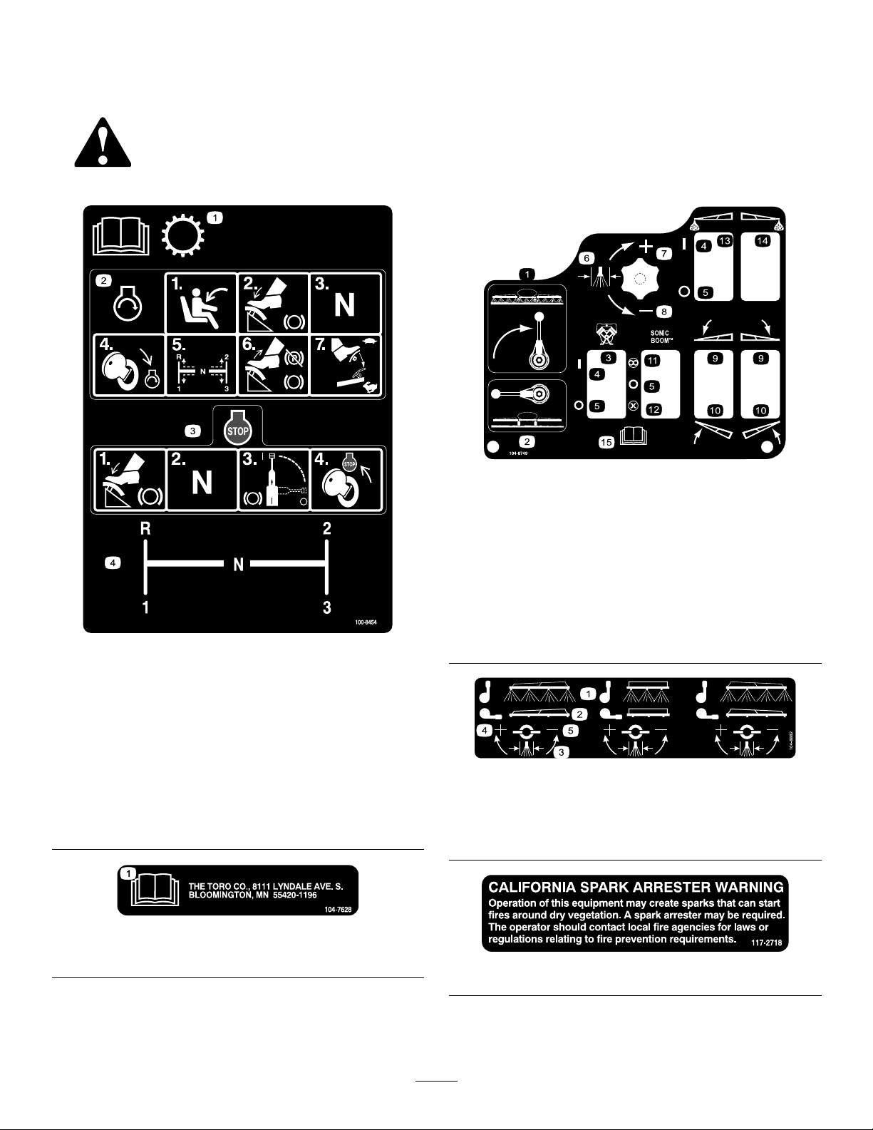
Safetydecalsandinstructionsareeasilyvisibletotheoperatorandarelocatednearanyareaofpotential
danger.Replaceanydecalthatisdamagedorlost.
100-8454
1.ReadtheOperator'sManualforinformationonthe
transmission.
2.Tostarttheengine,sitontheoperator'sseat,pressthe
brake,settherangeselectortoNeutral,turntheignition
keytoEngine-start,settherangeselectortothedesired
gear,releasethebrakeandparkingbrake,andpressthe
acceleratorpedaltothedesiredspeed.
3.Tostoptheengine,pressthebrake,settherangeselector
toNeutral,settheparkingbrake,andturntheignitionkey
toEngine-stop.
4.Rangeselectorgearpattern
104-8749
1.Sprayon
2.Sprayoff
3.Pump11.Automatic
4.On
5.Off13.Leftboomfoammarker
6.Spraypressure14.Rightboomfoammarker
7.Increase
8.Decrease
9.Lowertheboom.
10.Raisetheboom.
12.Manual
15.ReadtheOperator's
Manual.
104-8882
1.Sprayon
2.Sprayoff
3.Spraypressure
4.Increase
5.Decrease
1.ReadtheOperator'sManual.
104-7628
117–2718
8
Page 9
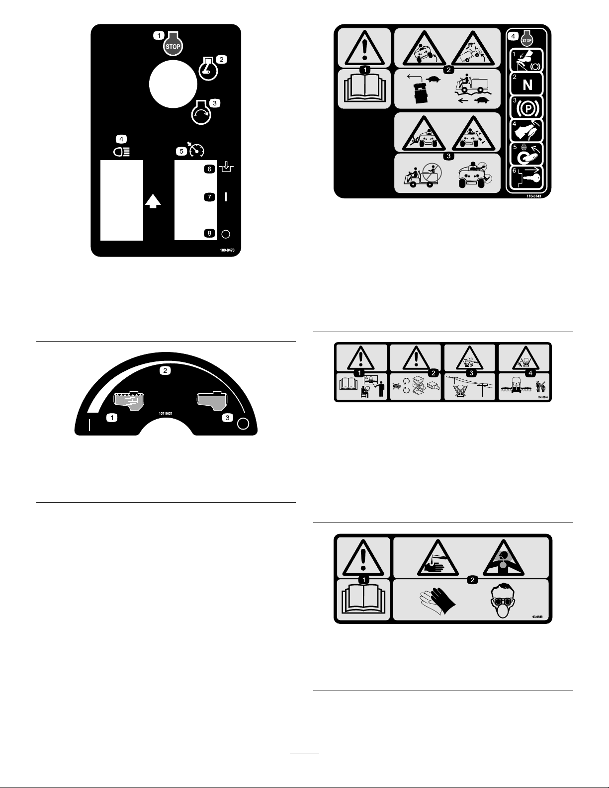
100-8470
1.Engine—stop5.Neutralenginespeedlock
2.Engine—run6.Engage
3.Engine—start
4.Headlights
7.On
8.Off
107-8621
1.Agitationon
2.Continuousvariable
setting
3.Agitationoff
110-5143
1.Warning—readtheOperator'sManual.
2.TippingHazard—driveslowlyoverroughterrainandwhen
turning.
3.Fallingandarm/leginjuryhazards—donotcarrypassengers
andkeeparmsandlegsinsideofthevehicleatalltimes.
4.Tostoptheengine,pressthebrake,movetherange
selectortoNeutral,settheparkingbrake,releasethebrake
pedal,turntheignitionkeytoEngine-stop,andremovethe
key.
110-5240
1.Warning—readtheOperator'sManualandreceivetraining
beforeoperating.
2.Warning—stayawayfrommovingparts,donotoperate
withcoversremoved.
3.Electricshockhazard,overheadpowerlines—stayaway
fromoverheadpowerlines.
4.Crushinghazard,boom—keepbystandersasafedistance
fromthemachine.
93-0688
1.Warning—readtheOperator'sManual.
2.Causticliquid/chemicalburnandtoxicgasinhalation
hazards—wearhand,skin,eye,andrespiratoryprotection.
9
Page 10
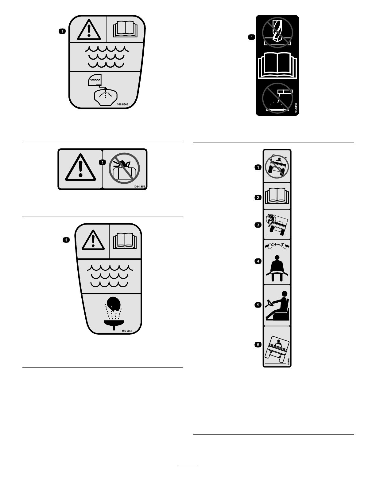
107-8640
1.Warning—readtheOperator'sManual;usefresh,clean
waterforrinsingthetank.
106-1355
1.Warning—donotenterthetank.
93-9850
1.Donotrepairorrevise—readtheOperator'sManual.
106-5051
1.Warning—readtheOperator'sManual;usefresh,clean
waterforrst-aidwashing.
104–8982
1.Avoidtippingthemachine.4.Alwaysweartheseatbelt.
2.ReadtheOperator’s
Manual.
3.Donotexitthemachine
whenitistipping.
5.Ifthemachinetips,hold
tightandbracewithyour
feet.
6.Ifthemachinebeginsto
tip,leanawayfromthe
directionitistipping.
10
Page 11
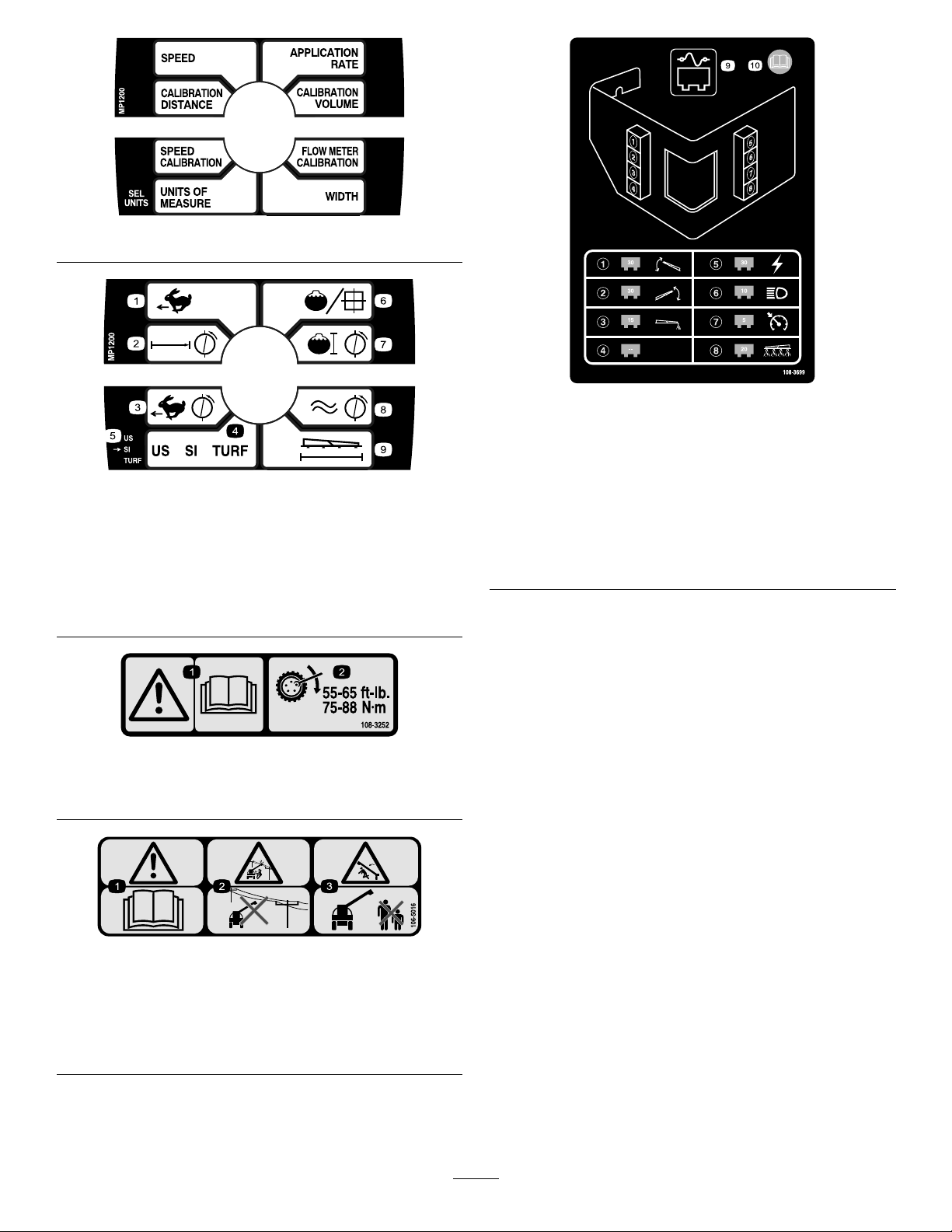
108-3306
108-3699
108-3308
CEUnitsOnly
1.Speed
2.Calibrationdistance7.Calibrationvolume
3.Speedcalibration
4.Unitsofmeasure
5.Selectunits
6.Applicationrate
8.Flowmetercalibration
9.Width
108-3252
1.Warning—readthe
Operator'sManual.
2.Torquelugnutsto55-65
ft-lb(75-88N·m).
1.30ampfuse,leftboom
actuator
2.30ampfuse,rightboom
actuator
3.15ampfuse,foammarker8.20ampfuse,spraysystem
4.Empty9.Fusepanel
5.30ampfuse,power10.ReadtheOperator's
6.10ampfuse,headlights
7.5ampfuse,cruisecontrol
Manualformore
information.
106-5016
1.Warning—readtheOperator'sManual.
2.Electricshockhazard,overheadpowerlines—stayaway
fromoverheadpowerlines.
3.Crushinghazard,boom—keepbystandersasafedistance
fromthemachine.
11
Page 12
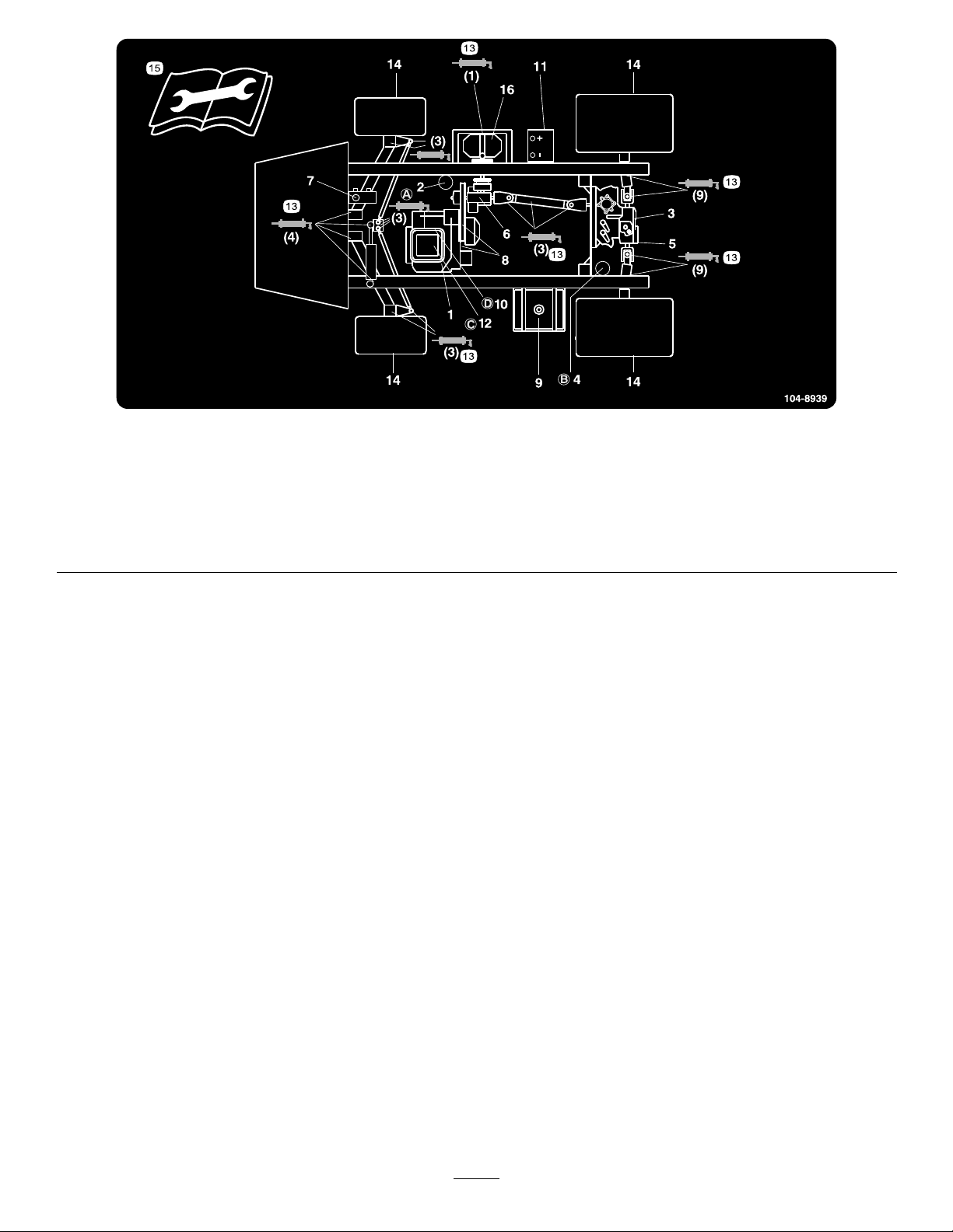
104-8939
1.Engineoillevel(dipstick)
2.Engineoillter6.Gearboxuidlevel10.Fuellter
3.Transaxle/hydraulicuid
level(dipstick)
4.Transaxlehydrauliclter
5.Hydraulicstrainer9.Fuel,unleadedonly
7.Brakeuid
8.Belts,steeringanddrive12.Aircleaner16.Pump
11.Battery15.Readtheinstructions
13.Grease
14.Tirepressure
beforeservicingor
performingmaintenance.
12
Page 13

Setup
LooseParts
Usethechartbelowtoverifythatallpartshavebeenshipped.
ProcedureDescription
1
2
3
4
5
90degreetting
Quickcoupler
Hoseadapter1
Fillreceptaclebracket1
Flange-headbolt,5/16x3/4inch
Anti-siphonhose1
SprayProMonitor
SprayProDecal
Bracket1
Flange-headbolt,3/4inch
Flangenut,1/4inch
Knob2
Washer2
Carriagebolt
Nopartsrequired
Nopartsrequired
Ignitionkey1
Operator'sManual
EngineOperator'sManual
PartsCatalog
OperatorTrainingMaterial
RegistrationCard
Pre-deliveryInspectionSheet
Qty.
Use
1
1
Installtheanti-siphonllreceptacle.
1
1
1
2
2
2
–
–
1
1
1
1
1
1
InstalltheSpray-Promonitor.
Checktheboomhingesprings.
Adjusttheboomstolevel.
Readthemanualsandviewthetraining
materialbeforeoperatingthemachine.
Note:Determinetheleftandrightsidesofthemachine
fromthenormaloperatingposition.
13
Page 14
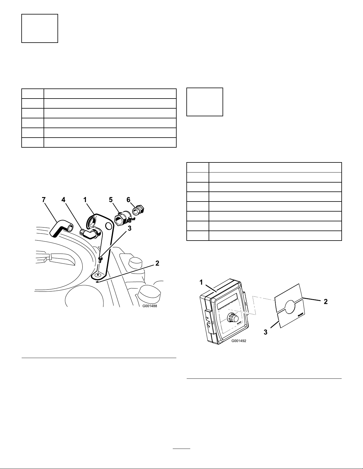
1
InstallingtheAnti-siphonFill
Receptacle
Partsneededforthisprocedure:
1
90degreetting
1
Quickcoupler
1Hoseadapter
1Fillreceptaclebracket
1
Flange-headbolt,5/16x3/4inch
1Anti-siphonhose
Procedure
1.Placethellreceptaclebracketoverthethreaded
holeinthetankandsecureitwithaange-headbolt
(5/16x3/4inch)(
Figure3).
4.Locktheadapterintoplacebyswingingthelevers
towardtheadapterandthensecurethemwiththe
hairpincotters(Figure3).
5.Installtheanti-siphonhosethroughthelargeopening
onthebracketandontothebarbedendofthe90
degreeelbowtting(Figure3).
Important:Donotlengthenthehosetoallow
contactwiththetankuids.
2
InstallingtheSprayPro Monitor
Partsneededforthisprocedure:
1
SprayProMonitor
1
SprayProDecal
1Bracket
2
Flange-headbolt,3/4inch
2
Flangenut,1/4inch
2Knob
2Washer
2
Carriagebolt
Figure3
1.Fillreceptaclebracket
2.Threadedholeinthetank6.Hoseadapter
3.Flangebolt,5/16x3/4inch
4.90degreeelbowtting
2.Placethethreadedendofthe90degreeelbowtting
throughthebracketandthreadthequickcoupleronto
it,securingittothebracket(Figure3).
Note:Installthettingwiththeopenendpointing
towardthelargeopeninginthebracketandtowardthe
tankopeningsothewaterwillarcintothetankwhen
youllit.
3.Installthehoseadapterintothequickcoupler
(Figure3).
5.Quickcoupler
7.Anti-siphonhose
Procedure
1.InstalltheSprayProDecaltothemonitor(Figure4).
Figure4
1.Spraypromonitor3.Decal,Lowerhalf
2.Decal,Upperhalf
Note:Besuretoorientthedecalasshownin
Figure19.
2.Installthemonitorbracketonthedash(Figure5)using
2ange-headbolts(1/4x3/4inch)and2angenuts
(1/4inch).
14
Page 15
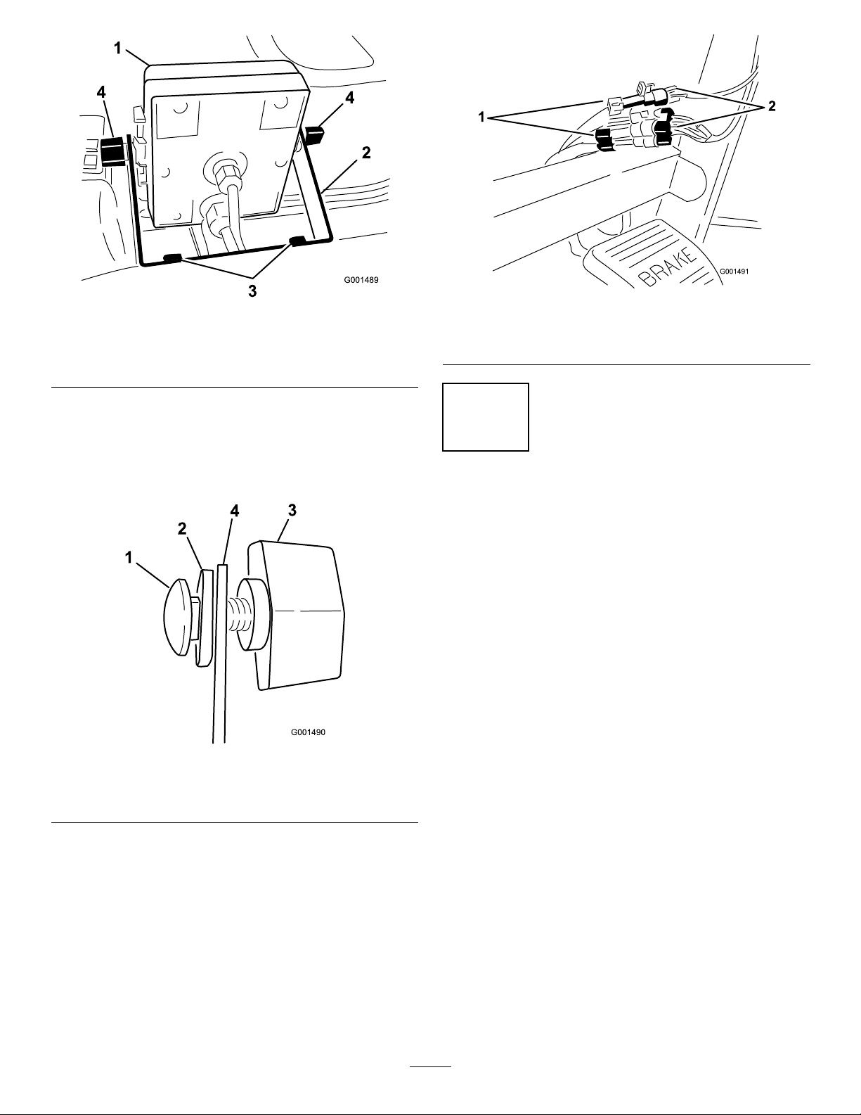
Figure5
1.SprayPromonitor
2.Bracket4.Knob
3.Looselyinstallthe2carriagebolts,rubber
washers,andknobsonthebracketasillustratedin
FigureFigure5andFigure6.
3.Flange-headbolts,
1/4x3/4inch
1.Connectorsfromthe
sprayer
3
Figure7
2.Connectorsfromthe
monitor
Note:Installthecarriageboltsandrubberwashers
insideofthebracketandtheknobsontheoutside.
Figure6
1.Carriagebolt
2.Rubberwasher4.Bracket
4.Removethelargegrommetfromtheholeinthedash
andthreadthecablesonthemonitorthroughthe
grommetandthedash.
5.Installthegrommetintothedash.
6.InstalltheSprayPromonitoroverthecarriagebolt
heads(
7.ConnecttheSprayProwireconnectorstothewire
connectorslocatedunderthedash(Figure7).
Figure5)andtightentheknobstosecureit.
3.Knob
CheckingtheBoomHinge Springs
NoPartsRequired
Procedure
Important:Operatingthespraysystemwiththeboom
hingespringsundertheincorrectcompressioncould
damagetheboomassembly.Measurethespringsand
usethejamnuttocompressthespringsto1.56inches
ifnecessary.
Thesprayerisshippedwiththeboomextensionsswung
forwardtofacilitatepackagingofthemachine.Thesprings
arenotfullytightenedatthetimeofmanufacturetoallowthe
boomstobeinthispositionfortransit.Beforeoperating
themachine,thespringsmustbeadjustedtothecorrect
compression.
1.Ifnecessary,removethepackingcomponentsthat
securetherightandleftextensionboomsduring
shipping.
2.Supporttheboomswhiletheyareextendedtothe
sprayposition.
3.Attheboomhinge,measurethecompressionofthe
upperandlowerspringswhiletheboomsareintheir
extendedposition(
A.Allspringsmustbecompresseduntilthey
measure1.56inches.
B.Usethejamnuttocompressanyspringthat
measuregreaterthan1.56inches.
Figure8).
15
Page 16
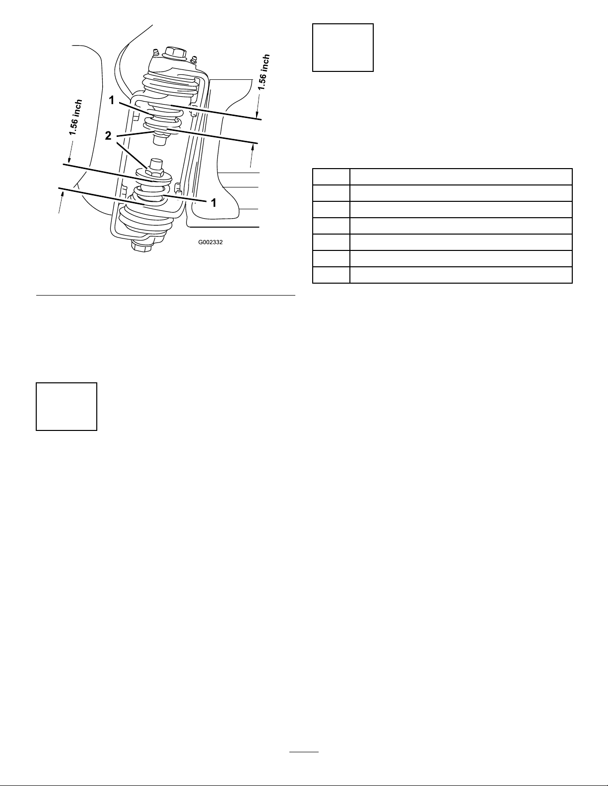
Figure8
1.Boomhingespring2.Jamnut
5
CompletingtheSetup: Learningmoreaboutyour product.
Partsneededforthisprocedure:
1Ignitionkey
1
Operator'sManual
1
EngineOperator'sManual
1
PartsCatalog
1
OperatorTrainingMaterial
1
RegistrationCard
1
Pre-deliveryInspectionSheet
4.Repeattheprocedureforeachspringonbothboom
hinges.
5.Movetheboomsintothetransport“X”position.See
OperatingtheBoomsintheOperationsectionfor
moreinformation.
4
AdjustingtheBoomstoLevel
NoPartsRequired
Procedure
1.Attheoperator'sposition,turntheignitionkeytoOn
toenergizethesystem.
2.Movetheboomsintopositionsothattheyarelevel
withtheground.
3.Removethekeyandexittheoperator'sposition.
Procedure
1.Readthemanuals.
2.ViewtheOperatortrainingmaterial.
3.CompletetheregistrationcardandreturntoToro.
4.Storethedocumentationinasafeplace.
4.Atthehinge,adjustthepositionofthebumperssothe
boomcannotmovepastlevelwiththeground.Take
caretomakesurethebumperislevel.
5.Tightentheboltandnuttolockthebumpersintothe
adjustedposition.Torquethefastenersto135-165
ft-lbs(183-223N-m).
Note:Thebumpermayexperiencesomecompressionover
time.Iftheboomsdropbelowlevel,usethisprocedureto
readjustthebumperpositionneeded.
16
Page 17
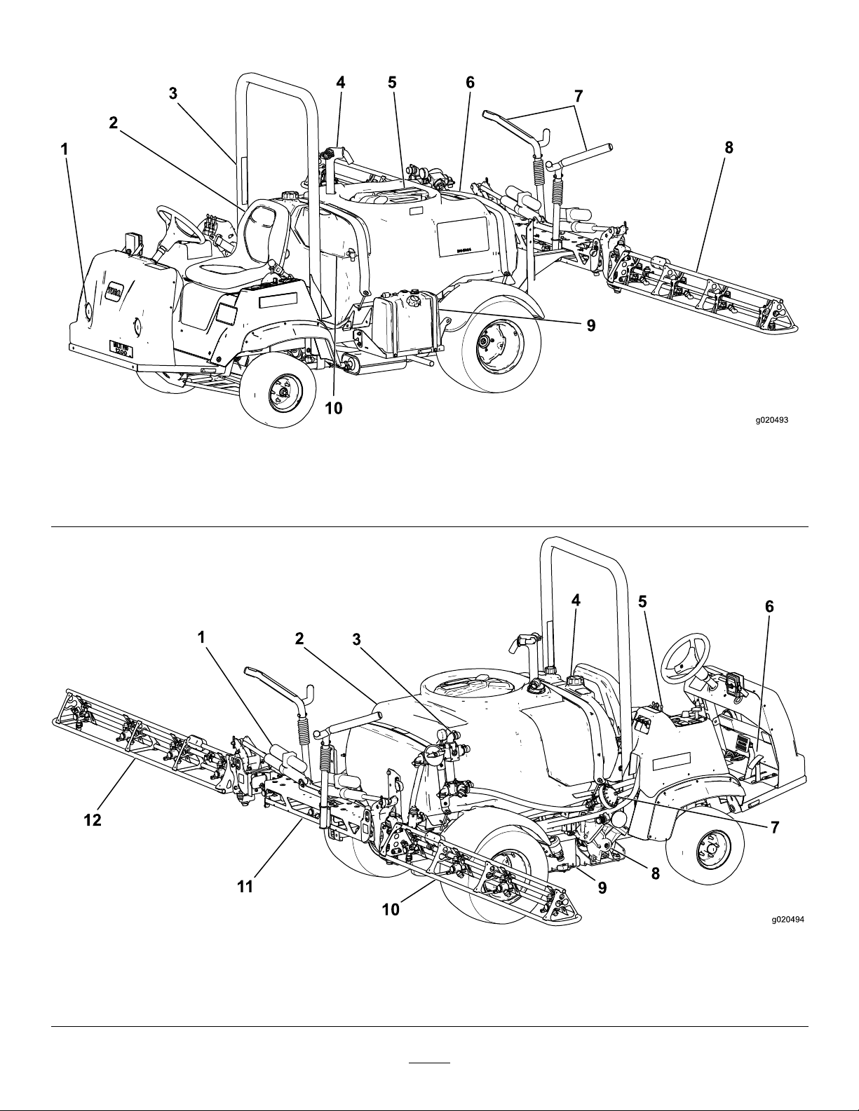
ProductOverview
Figure9
1.Headlight
2.Operator'sseat
3.Rolloverbar
4.Anti-SiphonReceptacle
5.Tanklid8.Boom
6.Chemicaltank
7.Boomtransportcradle10.Freshwatertank
9.Fueltank
Figure10
1.Boomcontrolcylinder4.Rinsetank7.Pumppressuredampener10.Rightboom
2.Chemicaltank5.Spraycontrolpanel
3.Agitationcontrolvalve6.Pedals9.Battery
8.Pump
17
11.Centerboom
12.Leftboom
Page 18
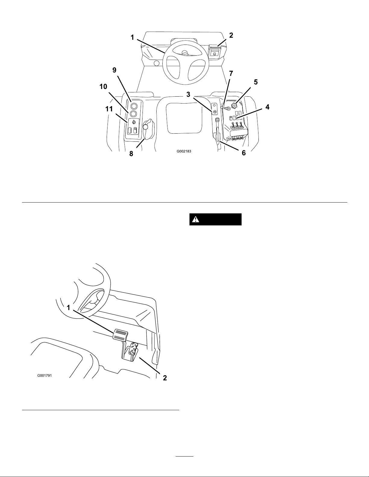
Controls
Figure11
1.Steeringwheel4.Sprayercontrols
2.Spray-Promonitor
3.Choke
5.Applicationrateknob
6.Parkingbrake9.Voltmeter
AcceleratorPedal
Theacceleratorpedal(Figure12)givesyoutheabilitytovary
groundspeedofthesprayer.Pressingthepedalincreases
groundspeed.Releasingthepedalwillslowthesprayerand
theenginewillidle.
7.Masterspraylever10.Hourmeter
8.RangeSelector
11.V ehiclecontrols
CAUTION
Brakescanbecomewornorcanbeadjusted
incorrectlyresultinginpersonalinjury.
Ifbrakepedaltravelstowithin1inch(2.5cm)ofthe
sprayeroorboard,thebrakesmustbeadjusted
orrepaired.
ParkingBrake
Theparkingbrakeisalargelevertotherightoftheseat.
(Figure13).Engagetheparkingbrakewheneveryouplan
onleavingtheseattopreventaccidentalmovementofthe
sprayer.Toengagetheparkingbrake,pullupandbackonthe
lever.Todisengage,pushitforwardanddown.Ifthesprayer
isparkedonasteepgrade,applytheparkingbrakeandplace
blocksatthedownhillsideofthewheels.
Figure12
1.Brakepedal2.Acceleratorpedal
BrakePedal
Usethebrakepedaltostoporslowthesprayer(Figure12).
18
Page 19
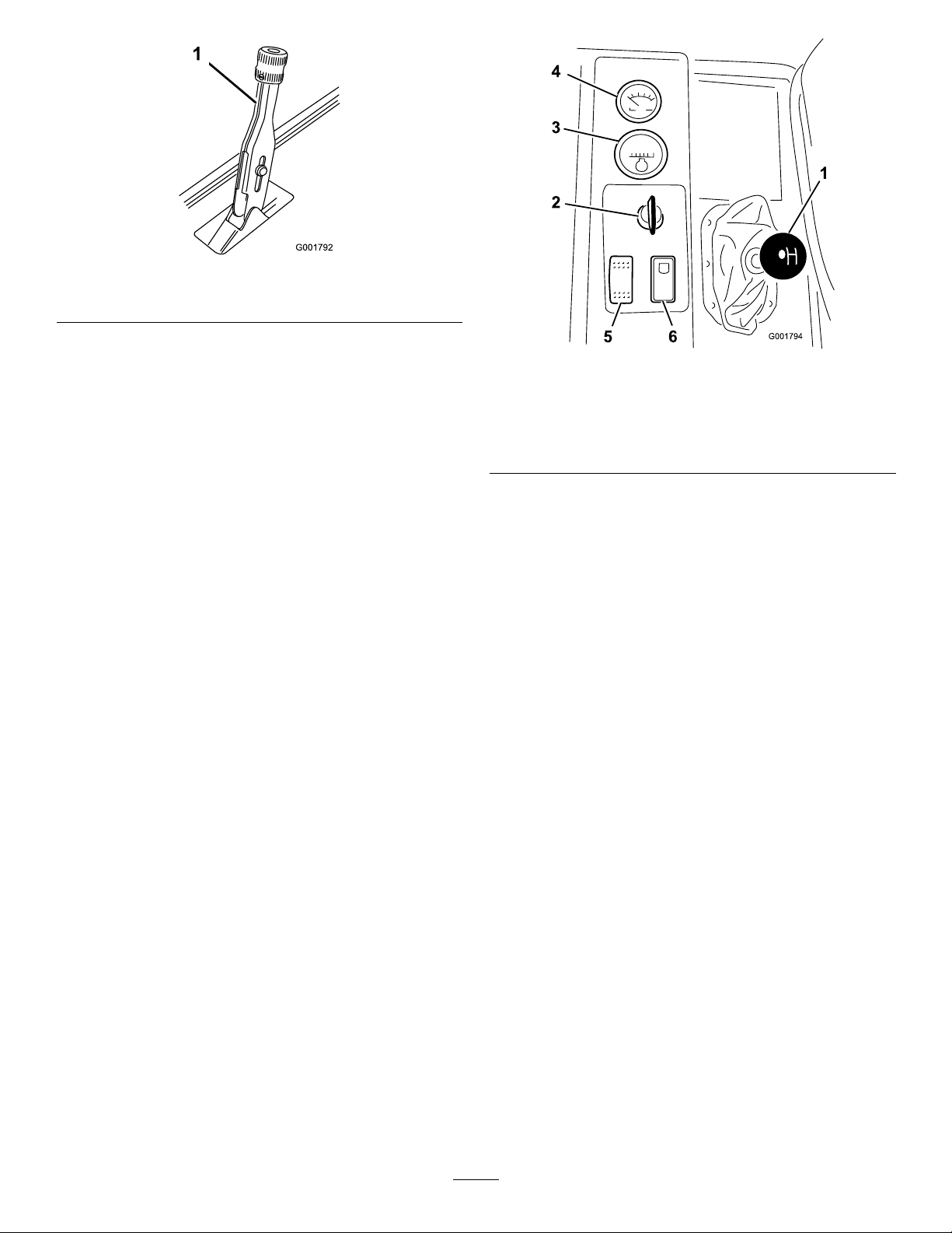
1.Parkingbrakelever
Figure13
ChokeControl
Thechokecontrolisasmallknobtotherightoftheseat.
Tostartacoldengine,pullthechokecontrolup.Afterthe
enginestarts,regulatethechoketokeeptheenginerunning
smoothly.Assoonaspossible,pushthecontroldowntothe
Offposition.Awarmenginerequireslittleornochoking.
RangeSelector
Therangeselector,locatedtotheleftoftheseat,has5
positions:3forwardspeeds,Neutral,andReverse(Figure14).
Theenginewillstartonlywhentherangeselectorisinthe
Neutralposition.Youmustalsofullypressthebrakewith
thesprayerstoppedtochangeranges.
Important:Donotshiftoutoforchangeranges
whilethevehicleismoving.Attemptingtochange
rangeswhilethevehicleismovingcandamagethe
transmission.Onlystoppingthesprayercompletely,
andfullyengagingthebrakewillsafelydisengagethe
lockingpinandallowtherangestobechanged.
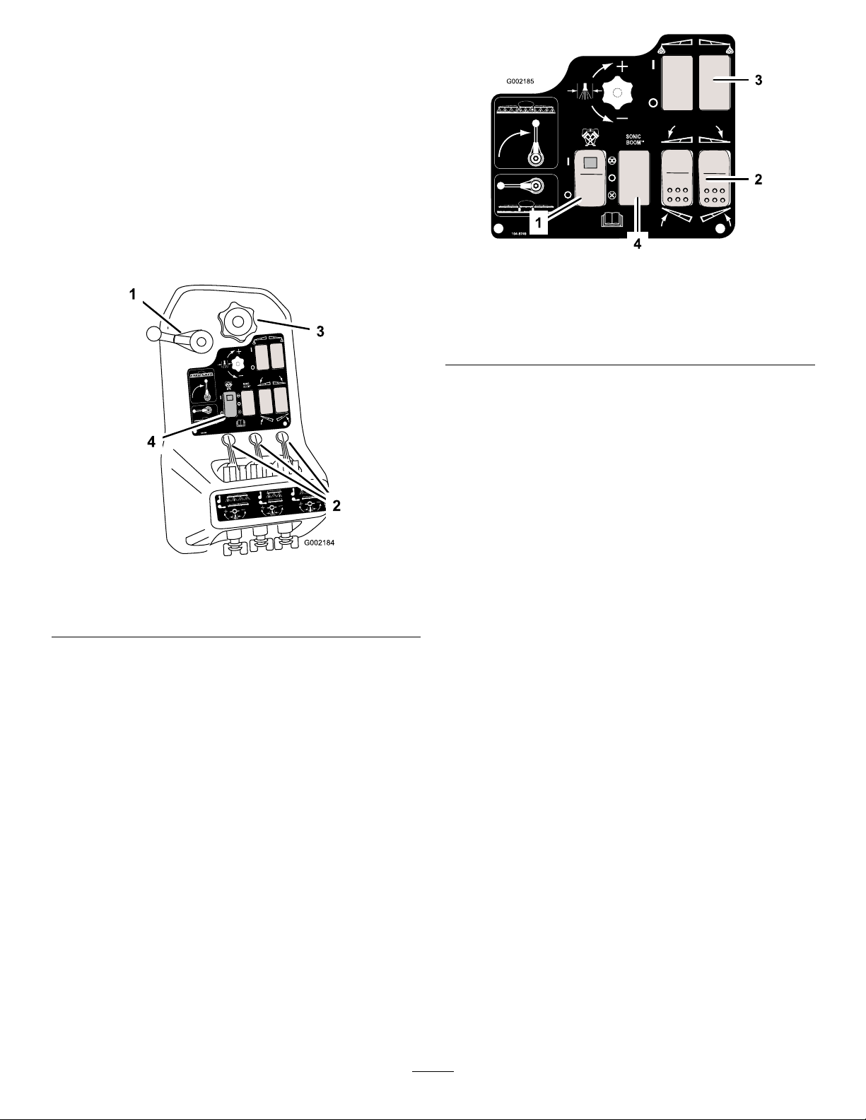
Figure14
1.RangeSelector
2.Ignitionswitch5.Headlightswitch
3.Hourmeter6.Neutralenginespeedlock
4.Voltmeter
switch
IgnitionSwitch
Theignitionswitch(Figure14),usedtostartandstopthe
engine,has3positions:Stop,Run,andStart.Rotatethekey
clockwisetotheStartpositiontostarttheengineandrelease
ittotheRunpositionwhenstarted.Rotatethekeytothe
Stoppositiontostoptheengine.
HourMeter
Thehourmeter(Figure14)indicatesthetotalnumberof
hourstheenginehasrun.Thehourmeterstartstofunction
wheneverthekeyisturnedtotheRunposition.
Voltmeter
Thevoltmeter(Figure14)indicatesthelevelofchargein
thebattery.Whenthebatteryisfullycharged,thevoltmeter
willreadinthecenterofthedialwhenthekeyisintheRun
positionwiththeengineoff.Whentheengineisrunningthe
voltmeterneedleshouldbetotheright.
HeadlightSwitch
Toggletheswitchtooperatetheheadlights(Figure14).Push
itforwardtoturnthelightsonandrearwardtoturnthemoff.
NeutralEngineSpeedLockSwitch
WhentherangeselectorisintheNeutralposition,youcan
usetheacceleratorpedaltospeeduptheengine,thenpush
thisswitchforwardtosettheengineatthatspeed.Thisis
necessarytorunthechemicalagitationwhilestationaryor
operatingattachmentssuchasthehandsprayer(
19
Figure14).
Page 20
Important:Therangeselectormustbeintheneutral
positionfortheswitchtowork.
FuelGauge
Thefuelgaugeislocatedontopofthefueltank,ontheright
sideofthemachineandshowstheamountoffuelinthetank.
MasterSprayLever
Themastersprayleverallowsyoutostartorstopthespray
operation.Rotatetheleverforwardtoenablethespraysystem
andrearwardtodisableit(Figure15).Whenthemasterspray
leverisintheOffposition,theSprayProscreenreads“Hold.”
Figure16
Figure15
1.Masterspraylever3.Applicationrateknob
2.Boomlevers4.Pumpswitch
BoomLevers
Theboomleversarelocatedattherearofthecontrolpanel
totherightoftheseat(Figure15).Pusheachleverdown
toturnthecorrespondingboomsectiononanduptoturn
themoff.Theseleverswillonlyaffectthespraysystemwhen
themastersprayleverison.
ApplicationRateKnob
Theapplicationrateknobislocatedonthecontrolpanelto
therightoftheseat(Figure15).Rotatetheknobclockwise
toincreasethespraysystempressureorcounterclockwiseto
decreasepressure.
1.Pumpswitch
2.Boomliftswitch,leftand
right
3.Foammarkerswitch,left
andright
4.Sonicboomswitch
BoomLift
Theboomliftswitchesareusedtoraisetheleftandright
boomrespectively(
Figure16).
FoamMarkerSwitchLocations
(Optional)
Ifyouinstalltheelectricboomlift,sonicboom,andfoam
markerkit,youwilladdswitchestothecontrolpanelfor
controllingtheiroperation.Thesprayercomeswithplastic
plugsintheselocations.
SonicBoom(Optional)
TheSonicBoomswitchisarockerswitchusedtooperatethe
SonicBoom.Toggleswitchforwardforautomatic,rearward
formanualandcenterforOff.
ApplicationRateControlValve
Thisvalvecontrolstheamountofuidthatisroutedtothe
boomsbydirectinguidowtotheboomsorthebypass
hosetothetank(Figure17).Tocontrolthisvalve,rotate
theapplicationrateknobontopofthevalvetoobtainthe
desiredpressure.
PumpSwitch
Thepumpswitchislocatedonthecontrolpaneltotheright
oftheseat(Figure16).Togglethisswitchforwardtorunthe
pumporrearwardtostopthepump.
Important:Onlyengagethepumpswitchwhenthe
engineisatlowidletoavoiddamagingthepumpdrive.
20
Page 21
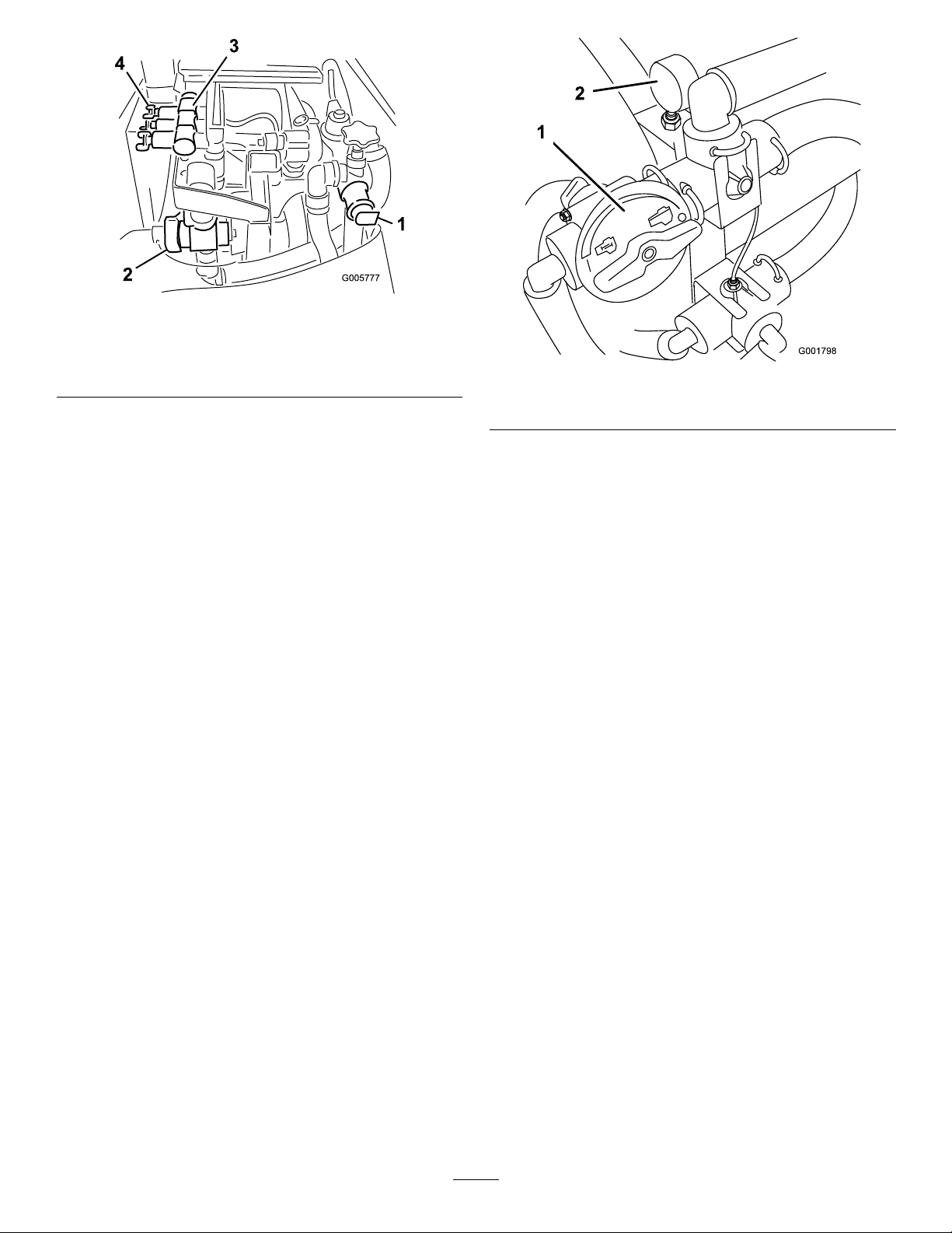
Figure17
1.Applicationratecontrol
valve
2.Flowmeter4.Boomby-passvalves
3.Boomvalves(3)
Flowmeter
Theowmetermeasurestheowrateoftheuidforuseby
theSprayPro™system(Figure17).
BoomValves
Thesevalvesturnthethreeboomsonoroff(Figure17).
BoomBypassValves
Theboombypassvalvesredirecttheuidowforaboom
tothetankwhenyouturnofftheboomsection.Y oucan
adjustthesevalvestoensurethattheboompressureremains
constantnomatterhowmanyboomsareon.Referto
CalibratingtheBoomBypassValves,intheOperationsection.
AgitationControlValve
Thisvalveislocatedontherightsideofthetank(Figure18).
Turntheknobonthevalvetothe9o'clockpositiontoturn
onthetankagitationandtothe3o'clockpositiontoturn
offthetankagitation.
Figure18
1.Agitationcontrolvalve2.Pressuregauge
Note:Foragitationtowork,thepumpmustbeonandthe
enginemustberunningaboveanidle.Ifyoustopthesprayer
andneedagitationon,placetherangeselectorintheNeutral
position,settheparkingbrake,presstheacceleratorpedal
totheoor,turnthepumpOnandturntheneutralengine
speedlockOn.
PressureGauge
Thepressuregaugeislocatedtotherightofthetank
(Figure18).Thisgaugeshowsthepressureoftheuidinthe
systeminpsiandkPa.Usethegaugetoadjusttheby-pass
valveswheneveryouchangenozzles.
Anti-siphonFillReceptacle
Tothefrontofthetankcoverisahosereceptaclewitha
threadedtting,a90degreebarbedtting,andashorthose
whichyoucandirecttowardthetankopening.Thisreceptacle
allowsyoutoconnectawaterhosetoitandllthetankwith
waterwithoutcontaminatingthehosewiththechemicalsin
thetank.
Important:Donotlengthenthehosetoallowcontact
withthetankuids.
21
Page 22
SprayPro™Monitor
US SI TURF
US
SI
TURF
MP1200
SEL
UNITS
UNITS OF
MEASURE
SPEED
CALIBRATION
WIDTH
FLOW METER
CALIBRATION
SPEED
CALIBRATION
DISTANCE
CALIBRATION
VOLUME
APPLICATION
RATE
MP1200
US English
CE Symbol
G002569
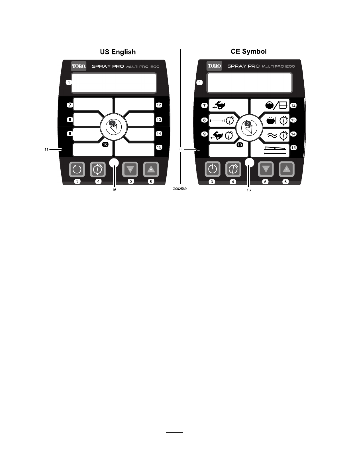
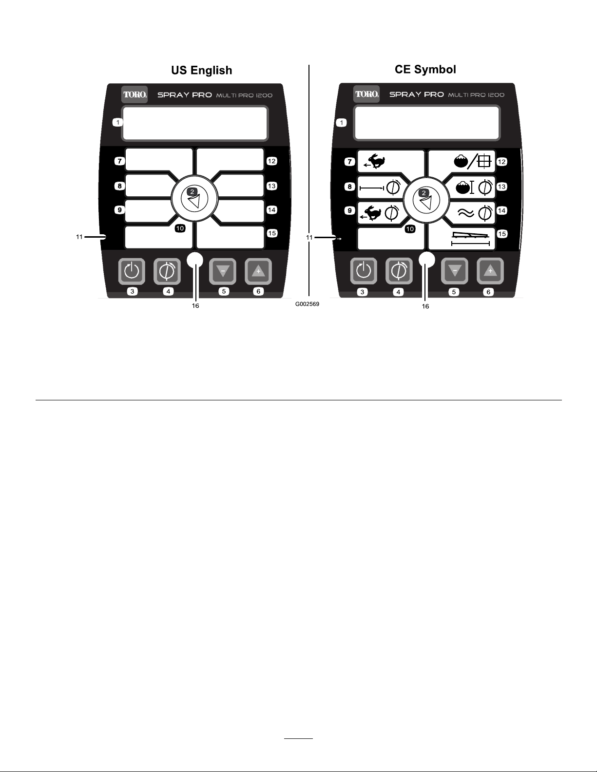
TheSprayPromonitordisplaysandmonitorsvarioussystem
performancedatasuchasvehiclespeedandapplicationrates.
Itdoesnotcontroltheapplicationrate.
ThemonitorhasanLCDscreenthatdisplaysthedatayou
select,aselectiondial,and4buttonsforcalibratingthe
monitor(Figure19).
1.LCDscreen
2.Selectiondial
3.Reset,calibrationbutton
4.Calibrate,calibrationbutton8.Calibrationdistance
5.Decrease,calibration
button
6.Increase,calibrationbutton
7.Speed1 1.Selectunits
MonitorDisplaySelectionDial
UsethedialtosettheLCDscreendisplaytothefollowing:
•Speed
Displaysthegroundspeedinmilesperhour(iftheUnits
ofMeasureissettoUSorTURF)orkilometersperhour
(iftheUnitsofMeasureissettoSI).
•CalibrationDistance
Recordsthedistancetraveledinfeet(USandTURF)or
meters(SI)usedwhencalibratingthespeed.
•SpeedCalibration
Alternatesthedisplayofthespeedcalibrationvalueand
therecordedcalibrationdistanceat3secondintervals.
Usethissettingtoadjustthespeedsensorcalibration.
•UnitsofMeasure
Displaysthecurrentmeasurementunitselectionas
follows:
–US(USgallonsperacre)
–SI(litersprehectare)
–TURF(USgallonsper1000sqft)
Figure19
9.Speedcalibration13.Calibrationvolume
10.Unitsofmeasure
12.Applicationrate16.LED
14.Flowmetercalibration
15.Width
•ApplicationRate
DisplaystheapplicationrateinUSgallonsperacre
(US),litersprehectare(SI),orUSgallonsper1000sqft
(TURF).
•CalibrationVolume
RecordsthevolumeinUSgallons(USandTURF)or
liters(SI)thatyouspray.Usethissettingtocalibratethe
owmeter.
Important:Inordertoaccuratelyrecordthevolume,
be sur e all thr ee boom v alv es ar e tur ned on.
sprayercannotaccuratelyrecordthetankvolume
whenanyoftheboomvalvesoff.
•FlowmeterCalibration
Alternatesthedisplayoftheowmetercalibrationvalue
andtherecordedcalibrationvolumeat3secondintervals.
Usethissettingtoadjusttheowmetercalibration.
•Width
Setsanddisplaystheboomwidth.Thedefaultsettingis
220inches(460cm).Thisisbasedon4nozzlesonthe
This
22
Page 23

rightandleftboomsand3onthecenterboomallspaced
20inches(50.8cm)apart.
CalibrationButtons
Themonitorhasthefollowingbuttons:
•Reset
ResetstheT otalVolume,SubVolume,Distance,T otal
Area,andSubAreadisplaysettingsto0.
•Calibrate
Usedtoenterandexitthecalibrationmode.
•Decrease
Reducesvaluesdisplayedonthescreenduringcalibration.
•Increase
Increasesvaluesdisplayedonthescreenduring
calibration.
CalibrationSettings
•BoomWidth
•UnitsofMeasure
•Speed/Distance
Specications
Note:Specicationsanddesignaresubjecttochange
withoutnotice.
Weightwithstandardspray
system,empty,without
operator
Weightwithstandardspray
system,full,withoutoperator
Maximumgrossvehicleweight
(GVW)(onlevelground)
Overalllengthwithstandard
spraysystem
Overallheightwithstandard
spraysystemtothetopofthe
boomsstoredintheXposition
Overallheightwithstandard
spraysystem
Overallwidthwithstandard
spraysystemboomsstoredin
theXposition
Groundclearance4.5inches(11.4cm)
Wheelbase
Tankcapacity(includestheCE
5%overow)
2,104lb(954kg)
3,661lb(1,660kg)
4,163lb(1,888kg)
133inches(337cm)
91inches(231cm)
70inches(178cm)
69inches(175cm)
62inches(157cm)
175USgallons(662L)
•Flowmeter
Attachments/Accessories
AselectionofToroapprovedattachmentsandaccessoriesis
availableforusewiththemachinetoenhanceandexpand
itscapabilities.ContactyourAuthorizedServiceDealeror
Distributororgotowww .Toro.comforalistofallapproved
attachmentsandaccessories.
23
Page 24
Operation
AddFuel
Note:Determinetheleftandrightsidesofthemachine
fromthenormaloperatingposition.
ThinkSafetyFirst
Pleasecarefullyreadallofthesafetyinstructionsanddecals
inthesafetysection.Knowingthisinformationcouldhelp
youorbystandersavoidinjury.
BeforeDrivingtheSprayerfor theFirstTime
ChecktheEngineOil
Theengineisshippedwithoilinthecrankcase;however,the
levelofoilmustbecheckedbeforeyourststarttheengine
andafteryouhaverunit.
1.Positionthemachineonalevelsurface.
2.Removethedipstickandwipeitwithacleanrag
(Figure20).Insertthedipstickintothetubeandmake
sureitisseatedfully.Removethedipstickandcheck
theoillevel.
DANGER
Incertainconditions,gasolineisextremely
ammableandhighlyexplosive.Areorexplosion
fromgasolinecanburnyouandothersandcan
damageproperty.
•Fillthefueltankoutdoors,inanopenarea,
whentheengineiscold.Wipeupanygasoline
thatspills.
•Neverllthefueltankinsideanenclosedtrailer.
•Donotllthefueltankcompletelyfull.Add
gasolinetothefueltankuntilthelevelis1/4to
1/2inch(6to13mm)belowthebottomofthe
llerneck.Thisemptyspaceinthetankallows
gasolinetoexpand.
•Neversmokewhenhandlinggasoline,andstay
awayfromanopenameorwheregasoline
fumesmaybeignitedbyaspark.
•Storegasolineinanapprovedcontainerand
keepitoutofthereachofchildren.Neverbuy
morethana30-daysupplyofgasoline.
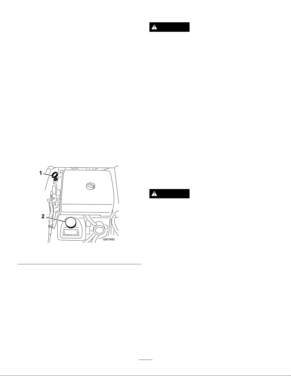
Figure20
1.Dipstick2.Fillercap
3.Iftheoillevelislow ,removethellercapfrom
thevalvecover(Figure20)andpouroilintothe
openinguntiltheoillevelisuptotheFullmarkonthe
dipstick;refertoServicingEngineOil,intheEngine
Maintenancesection,fortheproperoiltypeand
viscosity.Addtheoilslowlyandchecktheleveloften
duringthisprocess.Donotoverll.
4.Installthedipstickrmlyinplace.
ChecktheTirePressure
Checkthetirepressureevery8hoursordailytoensure
properlevels.Fillthetiresto18psi(124kPa).Also,check
thetiresforwearordamage.
•Donotoperatewithoutentireexhaustsystemin
placeandinproperworkingcondition.
DANGER
Incertainconditionsduringfueling,static
electricitycanbereleasedcausingasparkwhich
canignitethegasolinevapors.Areorexplosion
fromgasolinecanburnyouandothersandcan
damageproperty.
•Alwaysplacegasolinecontainersontheground
awayfromyourvehiclebeforelling.
•Donotllgasolinecontainersinsideavehicleor
onatruckortrailerbedbecauseinteriorcarpets
orplastictruckbedlinersmayinsulatethe
containerandslowthelossofanystaticcharge.
•Whenpractical,removegas-poweredequipment
fromthetruckortrailerandrefueltheequipment
withitswheelsontheground.
•Ifthisisnotpossible,thenrefuelsuch
equipmentonatruckortrailerfromaportable
container,ratherthanfromagasolinedispenser
nozzle.
•Ifagasolinedispensernozzlemustbeused,
keepthenozzleincontactwiththerimofthe
fueltankorcontaineropeningatalltimesuntil
fuelingiscomplete.
24
Page 25
RecommendedGasoline
g0131 14
1
2
Usefresh,clean,unleadedregulargasolinesuitablefor
automotiveuse(87pumpoctaneminimum).Leadedgasoline
maybeusedifunleadedregularisnotavailable.
Important:Neverusegasolinecontainingmethanol,
gasolinecontainingmorethan10%ethanol,gasoline
additives,orwhitegasbecauseenginefuelsystem
damagecouldresult.
FillingtheFuelTank
Thefueltankcapacityisapproximately5USgallons(19L).
Note:Thefueltankcapcontainsagaugewhichshowsthe
fuellevel;checkitfrequently.
1.Shuttheengineoffandsettheparkingbrake.
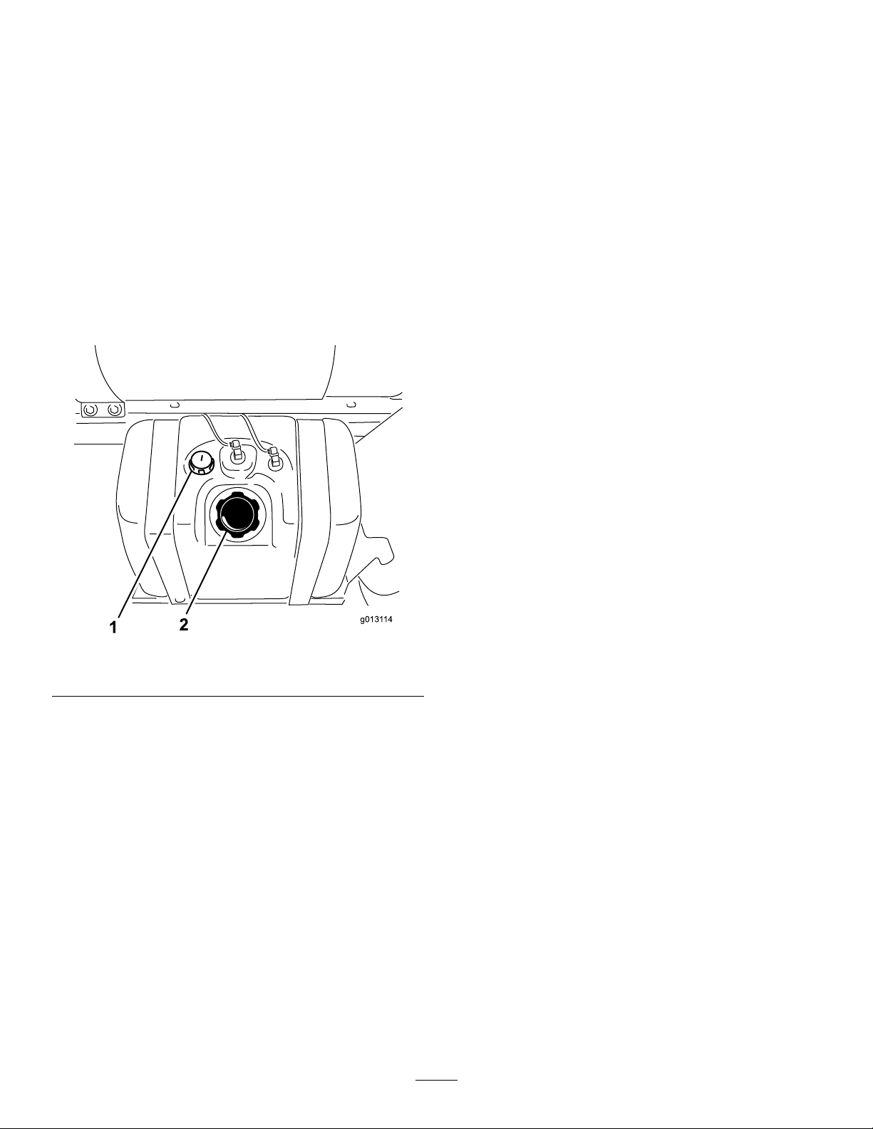
2.Cleantheareaaroundthefueltankcap(Figure21).
•Checktoseethatthelightsareworking.
•Turnthesteeringwheeltotheleftandrighttocheck
steeringresponse.
•Checkforoilleaks,looseparts,andanyothernoticeable
malfunctions.Makesuretheengineisoffandallmoving
partshavestoppedbeforecheckingforoilleaks,loose
parts,andothermalfunctions.
Ifanyoftheaboveitemsarenotcorrect,notifyyourmechanic
orcheckwithyoursupervisorbeforetakingthesprayerout
fortheday.Yoursupervisormaywantyoutocheckother
itemsonadailybasis,soaskwhatyourresponsibilitiesare.
DrivingtheSprayer
StartingtheEngine
1.SitintheOperator'sseat,insertthekeyintothe
ignitionswitch,androtatethekeyclockwisetotheRun
position.
2.Pressthebrakeandmovetherangeselectortothe
Neutralposition.
3.EnsurethatthepumpswitchisintheOffposition.
Figure21
1.Fuelgauge2.Fueltankcap
3.Removethefueltankcap.
4.Fillthetanktoaboutoneinchbelowthetopofthe
tank,(bottomofthellerneck).Thisspaceinthetank
allowsgasolinetoexpand.Donotoverll.
5.Installthefueltankcapsecurely .
6.Wipeupanyfuelthatmayhavespilled.
Pre-StartingChecks
Checkthefollowingitemseachtimeyoubeginusingthe
sprayerfortheday:
•Checkthetirepressure.
Note:Thesetiresaredifferentthancartires;theyrequire
lesspressuretominimizeturfcompactionanddamage.
•Checkalluidlevelsandaddtheappropriateamountof
specieduids,ifanyarefoundtobelow .
•Checkthebrakepedaloperation.
4.Iftheengineiscold,pullthechokeknobup.
Important:Donotusethechokeiftheengine
iswarm.
5.TurnthekeytotheStartpositionuntiltheenginestarts.
Important:DonotholdthekeyintheStart
positionformorethan10seconds.Iftheengine
hasnotstartedafter10seconds,wait1minute
beforetryingagain.Donotattempttopushortow
thesprayertostarttheengine.
6.Oncetheenginestarts,pushthechokeknobdown
slowly.
Driving
1.Pressthebrakepedal.
2.Pushtheparkingbrakeleverforwardtoreleaseit.
3.Movetherangeselectorintothedesiredrange.
4.Presstheacceleratorpedaltodriveorpressthebrake
tostop.
Note:Stoppingdistancemayvarydependingonthe
sprayerloadandspeed.
StoppingtheEngine
1.Pressthebraketostopthesprayer.
2.Pulltheparkingbrakeleverupandbacktosetit.
3.MovetherangeselectoroutofgearintotheNeutral
position.
4.TurntheignitionkeytotheStopposition.
25
Page 26

5.Removethekeyfromtheswitchtopreventaccidental
starting.
NewSprayerBreak-In
Toprovideproperperformanceandlongsprayerlife,follow
theseguidelinesfortherst100operatinghours:
•Checktheuidandengineoillevelsregularlyandbealert
forindicationsofoverheatinginanycomponentofthe
sprayer.
•Afterstartingacoldengine,letitwarmupforabout
15secondsbeforeaccelerating.
•Avoidhardbrakingsituationsfortherstseveralhoursof
newsprayerbreak-inoperation.Newbrakeliningsmay
notbeatoptimumperformanceuntilseveralhoursofuse
hascausedthebrakestobecomeburnished(broken-in).
•Avoidracingtheengine.
•Varythesprayerspeedduringoperation.Avoidfaststarts
andquickstops.
•RefertotheMaintenancesectionforanyspeciallowhour
checks.
AdjustingtheBoomstoLevel
Thefollowingprocedurecanbeusedtoadjustthehardstops
onthecenterboomtokeeptheleftandrightboomsatlevel.
1.Attheoperator'sposition,turntheignitionkeytoOn
toenergizethesystem.
2.Movetheboomsintopositionsothattheyarelevel
withtheground.
CAUTION
Chemicalsarehazardousandcancausepersonal
injury.
•Readthedirectionsonthechemicallabels
beforehandlingthechemicalsandfollow
allmanufacturerrecommendationsand
precautions.
•Keepchemicalsawayfromyourskin.Should
contactoccur,washtheaffectedareathoroughly
withsoapandcleanwater.
•Weargogglesandanyotherprotective
equipmentrecommendedbythechemical
manufacturer.
TheMulti-ProSprayerhasbeenspecicallydesignedtohave
highdurabilityinordertogiveitthelongsprayerlifeyou
need.Differentmaterialshavebeenchosenforspecic
reasonsatdifferentlocationsonyoursprayertomeetthis
goal.Unfortunatelythereisnosinglematerialwhichis
perfectforallforeseeableapplications.
Somechemicalsaremoreaggressivethanothersandeach
chemicalinteractsdifferentlywithvariousmaterials.Some
consistencies(e.g.wettablepowders,charcoal)aremore
abrasiveandleadtohigherthannormalwearrates.Ifa
chemicalisavailableinaformulationthatwouldprovide
increasedlifetothesprayer,usethisalternativeformulation.
Asalways,remembertocleanyoursprayerthoroughlyafter
allapplications.Thiswilldothemosttoensureyoursprayer
hasalongandtroublefreelife.
3.Removethekeyandexittheoperator'sposition.
4.Atthehinge,adjustthepositionofthebumperssothe
boomcannotmovepastlevelwiththeground.Take
caretomakesurethebumperislevel.
5.Tightentheboltandnuttolockthebumpersintothe
adjustedposition.Torquethefastenersto135-165
ft-lbs(183-223N-m).
Note:Thebumpermayexperiencesomecompressionover
time.Iftheboomsdropbelowlevel,usethisprocedureto
readjustthebumperpositionneeded.
OperatingtheSprayer
TooperatetheMulti-ProSprayerrstllthespraytank,then
applythesolutiontotheworkarea,andnallycleanthetank.
Itisimportantthatyoucompleteallthreeofthesestepsin
successiontoavoiddamagingthesprayer.Forexample,do
notmixandaddchemicalsinthespraytankatnightandthen
sprayinthemorning.Thiswouldleadtoseparationofthe
chemicalsandpossibledamagetothesprayercomponents.
FillingtheFreshWaterTank
Alwaysllthefreshwatertankwithcleanwaterbefore
handlingormixinganychemicals.
Thefreshwatertankislocatedatthefront,leftsideofthe
chemicaltank(Figure22).Itsuppliesasourceoffreshwater
foryoutowashchemicalsoffofyourskin,eyes,orother
surfacesinthecaseofaccidentalexposure.
Toopenthefreshwatertankspigot,turntheleveronthe
spigot.
26
Page 27
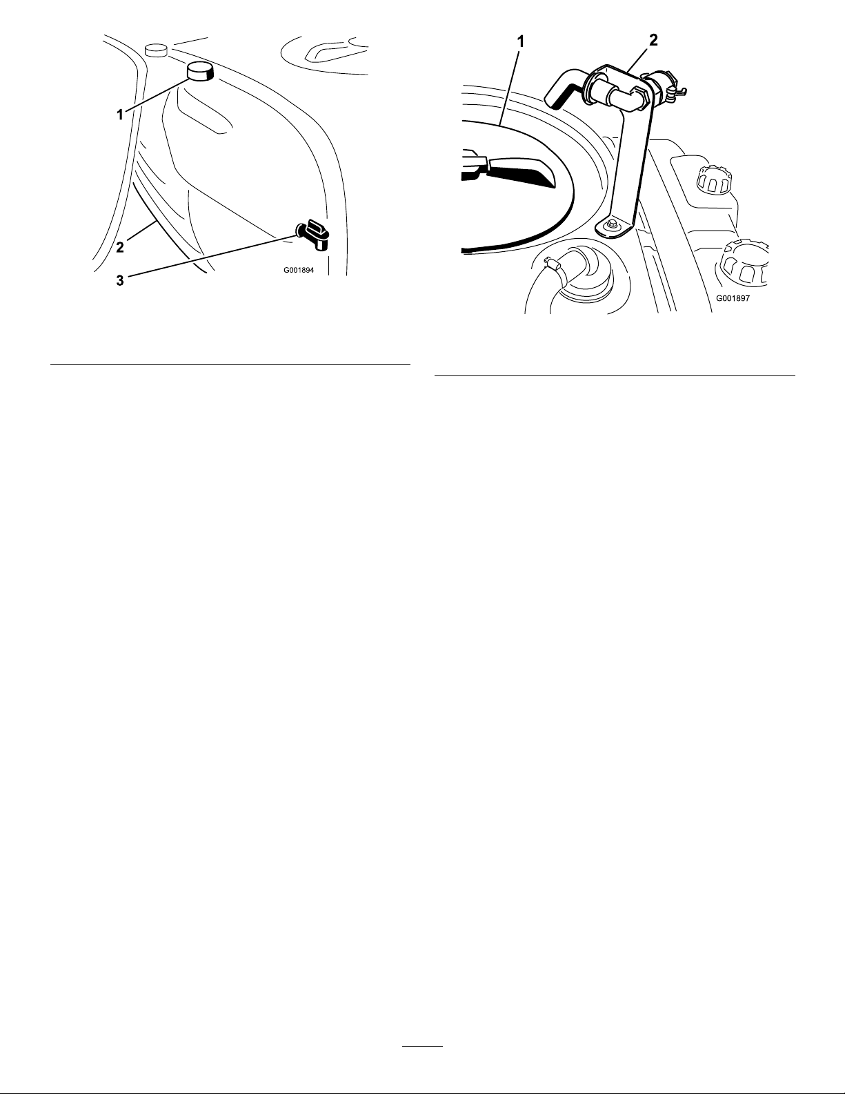
Figure22
G001897
1
2
1.Freshwatertank
2.Fillercap
3.Spigot
FillingtheSprayTank
Important:Ensurethatthechemicalsyouwillbeusing
arecompatibleforusewithViton(seethemanufacturer's
label;itshouldindicateifitisnotcompatible).Usinga
chemicalthatisnotcompatiblewithVitonwilldegrade
theO-ringsinthesprayer,causingleaks.
Important:Verifythattheproperapplicationratehas
beensetpriortollingthetankwithchemicals.
1.Stopthesprayeronalevelsurface,movetherange
selectortotheNeutralposition,stoptheengine,and
settheparkingbrake.
2.Ensurethatthetankdrainvalveisclosed.
3.Determinetheamountofwaterneededtomixthe
amountofchemicalyouneedasprescribedbythe
chemicalmanufacturer.
4.Openthetankcoveronthespraytank.
Thetankcoverislocatedinthecenterofthetopof
thetank(Figure23).Toopenit,turnthefronthalfof
thecovercounterclockwiseandswingitopen.You
canremovethestrainerinsideforcleaning.Tosealthe
tank,closethecoverandrotatethefronthalfclockwise.
Figure23
1.Tankcover
2.Anti-siphonllreceptacle
5.Add3/4oftherequiredwatertothespraytankusing
theanti-siphonllreceptacle.
Important:Alwaysusefreshcleanwaterinthe
spraytank.Donotpourconcentrateintoanempty
tank.
6.Starttheengine;increaseenginespeed(pressthe
acceleratorpedal)toapproximately1/2throttle.
7.SetthepumpswitchtotheOnposition.
8.Presstheacceleratorpedaltotheoorandsetthe
neutralenginespeedlocktotheOnposition.
9.SetthemasterspraylevertotheOffposition.
10.Turntheagitationcontrolvalvetothe9o'clock
positiontostartagitationinthetank.
11.Addtheproperamountofchemicalconcentratetothe
tank,asdirectedbythechemicalmanufacturer.
Important:Ifyouareusingawettablepowder,
mixthepowderwithasmallamountofwaterto
formaslurrybeforeaddingittothetank
12.Addtheremainingwatertothetank.
OperatingtheBooms
Theboomliftswitchesonthesprayercontrolpanelallows
youtomovetheboomsbetweentransportpositionand
spraypositionwithoutleavingtheOperator'sseat.Itis
recommendedtochangeboompositionswhilethemachine
isstationary.
Tochangetheboomposition:
1.Stopthesprayeronlevelground.
2.Usetheboomliftswitchestolowerbooms.Waituntil
theboomsreachthefull,extendedsprayposition.
27
Page 28

3.Whentheboomsneedtoberetracted,stopthesprayer
onlevelground.
4.Usetheboomliftswitchestoraisethebooms.Raise
theboomsuntilhavemovedcompletelyintoboom
transportcradleformingthe“X”transportposition
andtheboomcylindersarefullyretracted.
B.Withthebrakepressed,selectthedesiredgear
rangethenbegindrivingatmaximumspeed.
C.Verifythemonitordisplaysthecorrectapplication
rate.Ifneeded,manipulatetheapplicationrate
switchisuntilthemonitordisplaysthedesired
applicationrate.
Important:T opreventdamagetotheboom
actuatorcylinder,makesuretheactuatorsarefully
retractedbeforetransport.
TheBoomTransportCradle
Thesprayerisequippedwithaboomtransportcradlethat
hasauniquesafetyfeature.Intheeventofaccidentalboom
contactwithalowoverheadobjectwhileinthetransport
position,theboom(s)canbepushedoutofthetransport
cradles.Ifthisoccurs,theboomswillcometorestina
nearhorizontalpositiontotherearofthevehicle.While
theboomswillnotbedamagedduetothismovement,they
shouldbeimmediatelyputbackintothetransportcradle.
Important:Theboomscanbedamagedbytransporting
theminanypositionotherthanthe“X”transport
positionusingtheboomtransportcradle.
Toputtheboomsbackintothetransportcradle,lowerthe
boom(s)tothesprayposition,andthenraisetheboom(s)
backintothetransportposition.Makesuretheboom
cylindersarefullyretractedtopreventactuatorroddamage.
Spraying
Important:Inordertoensurethatyoursolution
remainswellmixed,usetheagitationfeaturewhenever
youhavesolutioninthetank.Foragitationtowork,the
pumpmustbeonandtheenginemustberunningabove
anidle.Ifyoustopthevehicleandneedagitationon,
placetherangeselectorintheNeutralposition,setthe
parkingbrake,presstheacceleratorpedaltotheoor,
turnonthepump,andturntheneutralenginespeed
lockOn.
Note:Thisprocedureassumesthatthepumpisonfromthe
FillingtheSprayTankprocedure.
1.Lowertheboomsintoposition.
2.SetthemasterspraylevertotheOffposition.
3.Settheindividualboomlevers,asneeded,totheOn
positions.
4.Drivetothelocationwhereyouwillbespraying.
5.TurntheSprayProselectiondialtotheApplication
Ratepositionandusetheapplicationrateswitchto
achievethedesiredrate.Todothis:
Note:Theboomby-passvalvemustbeproperly
calibratedfortheapplicationratetobeaccurate.Refer
toCalibratingtheBoomBy-PassValves.
A.EnsurethemastersprayleverisOffandthe
pumpisOn.
D.Returntothelocationwheresprayingistobegin.
6.SetthemasterspraylevertotheOnpositiontobegin
spraying.
Note:Whenthetankisnearlyempty ,theagitation
maycausefoaminginthetank.Inthiscase,turnthe
agitationcontrolvalvetothe3o'clockpositiontoturn
itoff.Alternatively,youcanuseananti-foamingagent
inthetank(ifcompatiblewiththechemicalyouare
using).
7.Whennishedspraying,setthemastersprayleverto
theOffpositiontoturnoffallbooms,thensetthe
pumpswitchtotheOffposition.
SprayingTips
•Donotoverlapareasthatyouhavepreviouslysprayed.
•Watchforpluggednozzles.Replaceallwornordamaged
nozzles.
•Usethemasterspraylevertostopthesprayowbefore
stoppingthesprayer.Oncestopped,placetherange
selectorinneutralandusetheneutralenginespeedlock
toholdtheenginespeeduptokeeptheagitationrunning.
•Youwillobtainbetterresultsifthesprayerismoving
whenyouturntheboomson.
•Watchforchangesintheapplicationratethatmay
indicatethatyourspeedhaschangedbeyondtherangeof
thenozzlesorthereisaproblemwiththespraysystem.
CleaningtheSprayer
Important:Y oumustalwaysemptyandcleanthe
sprayerimmediatelyaftereachuse.Failuretodoso
maycausethechemicalstodryorthickeninthelines,
cloggingthepumpandothercomponents.
Cleanthespraysystemaftereachsprayingsession.To
properlycleanthespraysystem:
•Usethreeseparaterinses.
•Useaminimumof50gallonsforeachrinse.
•Usethecleanersandneutralizersasrecommendedbythe
chemicalmanufacturers.
•Usepurecleanwater(nocleanersorneutralizers)forthe
lastrinse.
Therinsetankislocatedatthefront,rightsideofthe
chemicaltank(
Kit,youcanllthistankwithfreshwaterandautomatically
rinsethemaintank,boomsupplylinesandnozzles.
Figure24).IfyouinstalltheoptionalRinse
28
Page 29
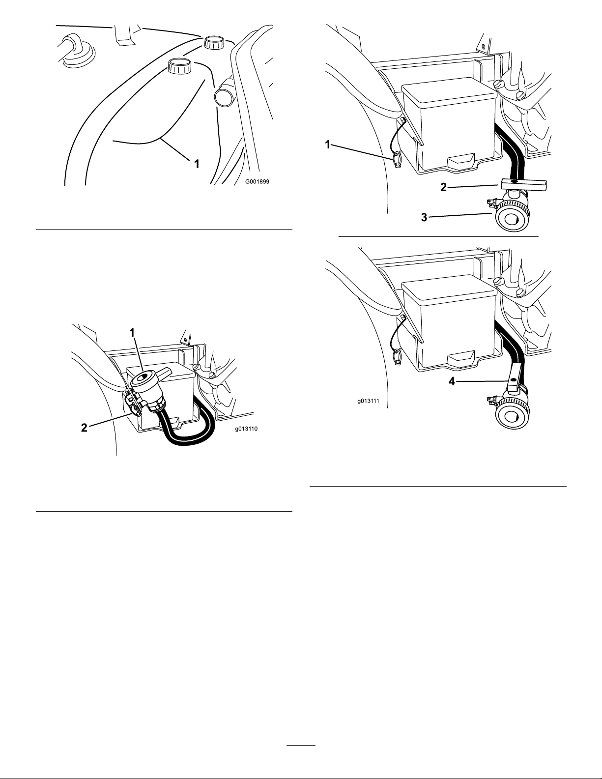
Figure24
g0131 10
1
2
g0131 11
1
2
3
4
1.Rinsetank(forusewiththeoptionalrinsekit,106-4842)
1.Stopthesprayer,settheparkingbrake,placetherange
selectorintheNeutralposition,andturnoffthe
engine.Thetankwilldraintoleftsideofthemachine.
2.Locatethetankdrainvalveontherightsideofthe
machine(Figure25).Thevalveisonthefenderbracket
nexttothebattery.
Figure26
Figure25
1.Tankdrain
2.Lynchpin
1.Lynchpin3.T ankdrain
2.Valveclosed4.Valveopen
3.Whenthetankhasdrainedcompletely ,closethedrain
valveandinstallthevalvetobracketwiththelynchpin
A.Removethelynchpinonthebracketsecuringthe
drainvalvetothemachineandletthevalverest
ontheground.
B.Openthevalvetodrainanyunusedmaterial
fromthetankanddisposeofitaccordingtolocal
codesandthematerialmanufacturer'sinstructions
(Figure26).Thisallowsanyresidualmaterialin
thelinetodrain.
removedpreviously(
4.Fillthetankwithatleast50USgallons(190L)ofclean
freshwaterandclosethecover.
Note:Youcanuseacleaning/neutralizingagentin
thewaterasneeded.Onthenalrinse,useonlyclean,
clearwater.
5.Starttheengine.
Figure26).
6.WiththerangeselectorintheNeutralposition,press
theacceleratorpedaltotheoorandsettheneutral
enginespeedlockswitchtotheOnposition.
7.EnsurethattheagitationcontrolvalveisintheOn
position.
8.SetthepumpswitchtotheOnpositionandusethe
applicationrateswitchtoincreasethepressuretoa
highsetting.
29
Page 30

9.Setthemasterboomswitchandboomcontrolswitches
totheOnpositionstobeginspraying.
10.Allowallofthewaterinthetanktosprayoutthough
thenozzles.
11.Checkthenozzlestoensurethattheyareallspraying
correctly.
12.SetthemasterboomswitchtotheOffposition,setthe
pumpswitchtotheOffposition,andstoptheengine.
13.Repeatsteps4through12atleast2moretimesto
ensurethatthespraysystemisfullycleaned.Onthe
lastcycle,runthelastfewgallonsofwaterthroughthe
drainvalvetoclearthedraintubing.
14.Cleanthestrainer;refertoCleaningtheSuction
StrainerintheCleaningsection.
Important:Ifyouusedwettablepowder
chemicals,cleanthestraineraftereachtank.
15.Usingagardenhose,sprayofftheoutsideofthe
sprayerwithcleanwater.
16.Removethenozzlesandcleanthembyhand.Replace
damagedorwornnozzles.
30
Page 31
CalibratingtheSprayPro
US SI TURF
US
SI
TURF
MP1200
SEL
UNITS
UNITS OF
MEASURE
SPEED
CALIBRATION
WIDTH
FLOW METER
CALIBRATION
SPEED
CALIBRATION
DISTANCE
CALIBRATION
VOLUME
APPLICATION
RATE
MP1200
US English
CE Symbol
G002569
Monitor
1.LCDscreen
2.Selectiondial
3.Reset,calibrationbutton
4.Calibrate,calibrationbutton8.Calibrationdistance
5.Decrease,calibration
button
6.Increase,calibrationbutton
7.Speed1 1.Selectunits
TheSprayPromonitorhasacalibrationmodethatallows
youtochangevarioussettingstocustomizethedisplayand
calibratethemonitortoyourneeds.Youcancalibrateor
changethefollowingsettings:
•BoomWidth
•UnitsofMeasure
•Speed
•Flowmeter
SettingtheBoomWidth
Thedefaultsettingis220inches(460cm).Thisisbasedon
4nozzlesontherightandleftboomsand3onthecenter
boomallspaced20inches(50.8cm)apart.Ifyouchangethe
spacingofthenozzles,youshouldchangetheboomwidthto
reectyourchangesasfollows:
1.Stopthesprayerandsettheparkingbrake.
2.SetthemasterspraylevertotheOffposition.
3.PressandholdtheCalibratebuttonuntilthemonitor
displays“CAL”andtheredlightonthemonitor
illuminates.
4.TurntheselectiondialtotheWidthposition.
Figure27
9.Speedcalibration13.Calibrationvolume
10.Unitsofmeasure
12.Applicationrate16.LED
14.Flowmetercalibration
15.Width
5.UsetheIncreaseorDecreasecalibrationbuttonsto
changetheboomwidthasneeded.
6.TurntheselectiondialtotheSubAreaposition.
7.PresstheCalibratebuttonuntiltheredlightturnsoff.
Youcanalsoexitthecalibrationmodebydrivingthe
sprayer.
SettingtheUnitsofMeasure
ThedefaultsettingfortheunitsofmeasureisUS.Youcan
alsochangetheunitstoSI(metric)orTURF.
1.Stopthesprayerandsettheparkingbrake.
2.SetthemasterspraylevertotheOffposition.
3.PressandholdtheCalibratebuttonuntilthemonitor
displays“CAL”andtheredlightonthemonitor
illuminates.
4.TurntheselectiondialtotheUnitsofMeasureposition.
5.UsetheIncreaseorDecreasecalibrationbuttonsto
selectdesiredunitsofmeasure.
6.PresstheCalibratebuttonuntiltheredlightturns
off.Youcanalsoexitcalibrationmodebydrivingthe
sprayer.
31
Page 32

CalibratingtheFlowmeter
Note:Performthiscalibrationprocedureeachtimenozzles
arechangedtoensurethegreatestaccuracy .
13.PresstheCalibratebuttonuntiltheredlightturns
off.Youcanalsoexitcalibrationmodebydrivingthe
sprayer.
TheSprayPromonitorcomesapproximatelycalibratedfor
theowmeter.Completethefollowingproceduretonetune
theowmetercalibration:
1.Settheparkingbrake.
2.Fillthesprayertankwithaknownquantityofwater,at
least100USgallons(380L).
Note:Donotrelyonthemarksonthesideofthetank
formeasuringthewaterforthisprocedure.Theyare
approximatemeasurements,butnotaccurateenough
forthiscalibration.
3.SetthepumpswitchtotheOnpositiontostartthe
pump.
4.Setallthreeboomleversandthemasterspraylever
totheOnposition.Runtheboomsonlyuntiltheair
ispurgedfromtheline,thenturnthemoffusingthe
masterspraylever.
Important:Inordertoaccuratelyrecordthe
volume,allthreeboomvalves
during this pr ocedur e.
onlythemasterspraylever.Thissprayercannot
accuratelyreportcalibrationvolumewhenanyof
theboomvalvesareoff.
5.TurntheselectiondialtotheCalibrationVolume
position.
6.PressandholdtheResetcalibrationbuttonuntilthe
displayreads“0”.
7.SetthemasterspraylevertotheOnpositionandrun
theboomsuntilallthewaterisoutofthetank,then
stopthemusingthemasterspraylever.
8.Comparethevolumedisplayedonthemonitortothe
volumeofwateryouputintothetank.
Turntheboomsoffusing
must r emain on
•Ifthevolumesarethesame,youdonotneedto
calibratethemonitoranyfurther.
•Ifthevaluesaredifferent,continuewiththerest
ofthisprocedure.
9.TurntheselectiondialtotheFlowmeterCalibration
position.
10.PressandholdCalibratebuttonuntiltheredlighton
themonitorilluminates.
Thedisplaywillalternatebetweentheowmeter
calibrationvalue(indicatedbytheword“CAL”onthe
monitor)andthecalibrationvolume.
11.Whenthecalibrationvolumeisdisplayed,usethe
IncreaseorDecreasecalibrationbuttonstochangeit
totheamountofwateryouputinthetank.
12.Whenthedisplaybeginsalternatingagain,the
owmetercalibrationvaluewillhavechanged;write
thisnumberdownandsaveit.Thisisthecalibration
valueforyoursprayer.
CalibratingtheSpeedSensor
TheSprayProcomesapproximatelycalibratedforthespeed
sensor.Completethefollowingproceduretonetunethe
speedsensorcalibration:
1.Checkandllalltires;refertoCheckingTirePressure
intheDriveSystemMaintenancesection.
2.Fillthefreshwatertank.
3.Fillthesprayertankhalf-fullofwater.
4.Selectastraight,attrackofgroundthatissimilarto
yourturfconditions.
Note:Usingaroadorotherpavedsurfacecouldcause
aninaccuratereadingwhenyoulaterdrivethesprayer
onturf.
5.Measure500feet(or150m),markingboththestart
andendpoints.
6.Positionthesprayeratthestartingpoint.
7.SetthepumpandthemasterspraylevertotheOff
position.
8.TurntheselectiondialtotheCalibrationDistance
position.
9.PressandholdtheResetcalibrationbuttonuntilthe
displayreads“0”.
10.Drivethemachinefromthestartpointyoumarkedto
the500ft(or150m)endpoint.
11.Whenyoureachtheendpointstopthemachine.
12.Settheparkingbrake.
13.Lookatthedistancedisplayedonthemonitor.
•Ifitreads“500feet(or150m)”,youdonotneed
tocalibratethemonitoranyfurther.
•Ifitdoesnotread“500feet(or150m)”,continue
withtherestofthisprocedure.
14.WiththeselectiondialsettotheSpeedCalibration
position,pressandholdtheCalibratebuttonuntil
themonitordisplays“CAL”andtheredlightonthe
monitorilluminates.
Thedisplaywillalternatebetweenthedistanceandthe
speedcalibrationvalue(“CAL”shown).
15.Whenthedistanceisdisplayed,usetheIncreaseor
Decreasecalibrationbuttonstochangeitto500feet
(or150m).
16.Whenthedisplaybeginsalternatingagain,thespeed
calibrationvaluewillhavechanged;writethisnumber
downandsaveit.Thisisthecalibrationvalueforyour
sprayer.
32
Page 33
17.PresstheCalibratebuttonuntiltheredlightturns
off.Youcanalsoexitcalibrationmodebydrivingthe
sprayer.
ResettinganOFLCondition
Ifthemonitorreads“OFL”,itindicatesthatyouhave
exceededthemonitorscreendimensions.Pressandholdthe
Resetcalibrationbuttontosetthedisplayto0.
CalibratingtheBoomBypass Valves
Beforeusingthesprayerforthersttimeorifthenozzlesare
changed,adjusttheboombypassvalvessothatthepressure
andapplicationrateremainsthesameforallboomswhenyou
turnoneormoreboomsoff.
Note:Theboombypassvalvesmustbecalibratedeachtime
thenozzlesarechanged.
Selectanopenatareatoperformthisprocedure.
1.Fillthespraytankwithcleanwater.
2.Puttheextensionboomsdown,ifinstalled.
3.SetthedialontheSprayPromonitortoApplication
Rate.
4.PlacespeedrangeinNeutralandengagetheparking
brake.
5.Startthesprayerengine.
6.SetthepumpswitchtotheOnpositiontostartthe
pump.
7.Presstheacceleratortotheoorandholdandsetthe
neutralenginespeedlockswitchtotheOnposition.
Figure28
1.Boombypassvalves
13.Turntheboomonandofftoverifythepressuredoes
notchange.
14.Repeatsteps11through13fortheotherbooms.
15.Drivethesprayeratthedesiredspeedwhilespraying
andturneachboomoffindividually.Thepressureon
thegaugeshouldnotchange.
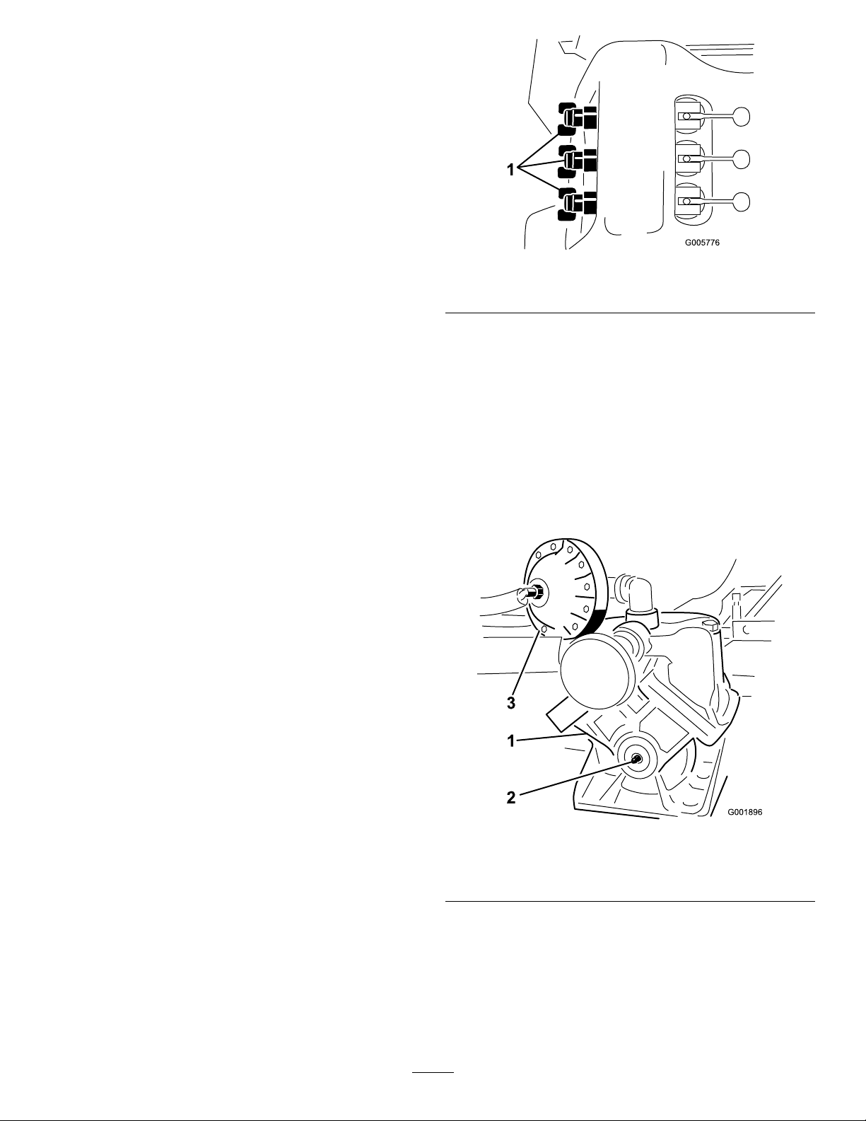
Pump
Thepumpislocatednearthefrontofthetankontheright
side(Figure29).
8.Setallthreeboomleversandthemasterspraylever
totheOnposition.
9.Usetheapplicationrateknobtoadjustthepressureas
readonthepressuregaugeuntilitisintherangefor
thenozzlesyouinstalledonthebooms(typically40
psi[2.75bar]).
10.Recordthereadingonthepressuregauge.
11.Turnoffoneoftheboomsusingtheappropriateboom
lever.
12.Adjusttheboombypassvalve(Figure28)underthe
boomcontrolvalvefortheboomyouturnedoffuntil
thepressurereadingonthegaugeisthesameasitwas
instep
9.
Figure29
1.Pump3.Pressuredampener
2.Greasetting
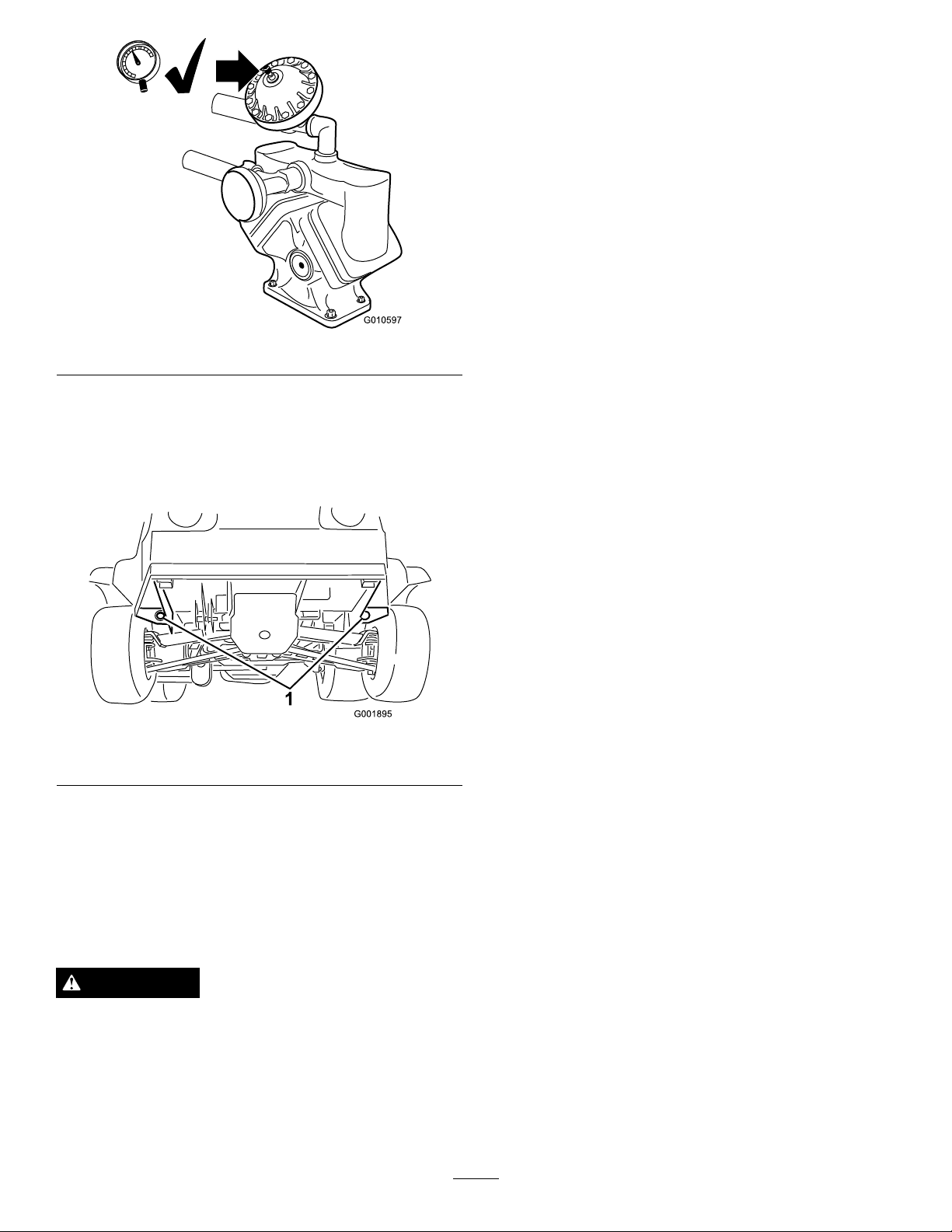
AdjustingtheAirPressureinDampener
Theairpressureinthedampeneronthepumpissetat15psi
(1bar)bythemanufacturer.Therecommendedpressurein
thedampeneris1/3ofthesprayingpressure.Ifusingaspray
pressuregreaterthan45psi(3.1bar)adjustthedampener
accordingly.
33
Page 34
G010597
Figure30
TransportingtheSprayer
Formovingthesprayerlongdistances,useatrailer.Secure
thesprayertothetrailer.Figure31illustratesthefront
tie-downpoints.
1.Afxatowlinetotheframe.
2.PuttherangeselectorintheNeutralpositionand
releasetheparkingbrake.
3.Towthesprayeratlessthan5mph(8kph).
Figure31
1.Tiedownpoints
Thereartie-downpointsaretwosteelloopsundertheback
oftheframejustinfrontoftheadjustableboomframe.
TowingtheSprayer
Incaseofanemergency,thesprayercanbetowedforashort
distance.However,wedonotrecommendthisasastandard
procedure.
WARNING
Towingatexcessivespeedscouldcausealossof
steeringcontrol,resultinginpersonalinjury.
Nevertowthesprayerfasterthan5mph(8kph).
Towingthesprayerisatwopersonjob.Ifthemachinemust
bemovedaconsiderabledistance,transportitonatruckor
trailer;refertoTransportingtheSprayer.
34
Page 35

Maintenance
Note:Determinetheleftandrightsidesofthemachinefromthenormaloperatingposition.
RecommendedMaintenanceSchedule(s)
MaintenanceService
Interval
Aftertherst8hours
Aftertherst50hours
Beforeeachuseordaily
Every25hours
Every50hours
Every100hours
MaintenanceProcedure
•T orquethewheellugnuts.
•Checkthedrivebelt.
•Checkthesteeringpumpbelttension.
•Replacethehydrauliclter.
•Changetheengineoil.
•Checkpumpdampenerpressure.
•Cleantheenginerotatingscreen.
•Checktheengineoil.
•Checkthetirepressure.
•Checkpumpdampenerpressure.
•Cleanthesuctionstrainer.(moreoftenwhenusingwetablepowders)
•Cleanandoilthefoamaircleaner(moreoftenindusty ,dirtyconditions).
•Lubricatethepump.
•Checkthebatterycableconnections.
•Checkthebatteryelectrolytelevel.
•Lubricateallgreasettings.
•Lubricatetheboomhinges.
•Cleantheenginerotatingscreen(moreoftenindusty ,dirtyconditions).
•Replacethepaperaircleanerelement(moreoftenindusty ,dirtyconditions).
•Changetheengineoil,includingsyntheticoil(moreoftenwhenoperatingunder
heavyloadorinhightemperature).
•Replacetheengineoillter.
•Replacethefuellter.
•T orquethewheellugnuts.
•Inspecttheconditionandwearofthetires.
•Checkfrontwheeltoe-in.
•Inspectthebrakes.
•Checkthesteeringpumpbelttension.
Every200hours
•Changethesparkplugs.
•Checktheparkingbrake.
•Checkthedrivebelt.
•Checkthetransaxle/hydraulicuid.
•Inspectallhosesandconnectionsfordamageandproperattachment.
•Cleantheowmeter.(Moreoftenwhenusingwettablepowders)
35
Page 36
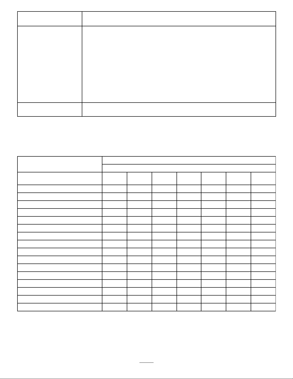
MaintenanceService
Every400hours
Interval
MaintenanceProcedure
•Greasetheactuatorrodbearings.
•Completeallyearlymaintenanceprocedurespeciedintheengineoperator's
manual.
•Inspectthefuellines.
•Drainandcleanthefueltank.
•Inspectthepumpdiaphragmandreplaceifnecessary.(seeanAuthorizedT oro
ServiceDistributor)
•Inspectthepressuredampenerbladderandreplaceifnecessary.(seeanAuthorized
ToroServiceDistributor)
•Inspectthepumpcheckvalvesandreplaceifnecessary.(seeanAuthorizedT oro
ServiceDistributor)
•Changethepumpdrivegearboxuid.
•Checkboomactuatorhydraulicoilforairbubbles.
•Inspectthecenterboomnylonpivotbushings.
Every800hours
Important:Refertoyourengine
DailyMaintenanceChecklist
Duplicatethispageforroutineuse.
Checkthebrakeandparkingbrake
operation.
Checkthegearshift/neutraloperation.
Checkthefuellevel.
Checktheengineoillevel.
Checkthetransaxleoillevel.
Inspecttheairlter.
Inspecttheenginecoolingns.
Checkanyunusualenginenoises.
Checkanyunusualoperatingnoises.
Checkthetirepressure.
Checkforuidleaks.
Checktheinstrumentoperation.
Checktheacceleratoroperation.
Cleanthesuctionstrainer.
Checktoe-in.
Lubricateallgreasettings.
Touchupanddamagedpaint.
1
•Changethetransaxle/hydraulicuidandcleanstrainer.
•Replacethehydrauliclter.
Operator's Man ual
Fortheweekof: MaintenanceCheckItem
Mon.Tues.Wed.Thurs.Fri.
foradditionalmaintenanceprocedures.
Sat.Sun.
1
Immediatelyaftereverywashing,regardlessoftheintervallisted
36
Page 37
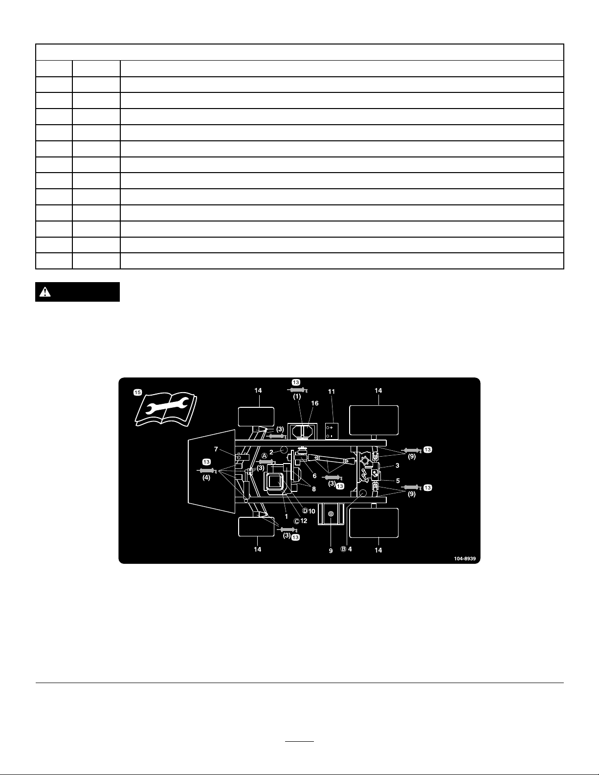
NotationforAreasofConcern
Inspectionperformedby:
ItemDate
1
2
3
4
5
6
7
8
9
10
11
12
CAUTION
Ifyouleavethekeyintheignitionswitch,someonecouldaccidentlystarttheengineandseriouslyinjure
youorotherbystanders.
Information
Removethekeyfromtheignitionanddisconnectthewire(s)fromthesparkplug(s)beforeyoudoany
maintenance.Setthewire(s)asidesothatitdoesnotaccidentallycontactthesparkplug(s).
Figure32
Servicelocations
1.Engineoillevel(dipstick)
2.Engineoillter6.Gearboxuidlevel10.Fuellter
3.Transaxle/hydraulicuid
level(dipstick)
4.Transaxlehydrauliclter
5.Hydraulicstrainer9.Fuel,unleadedonly
7.Brakeuid
8.Belts,steeringanddrive12.Aircleaner16.Pump
11.Battery15.Readtheinstructions
13.Grease
14.Tirepressure
beforeservicingor
performingmaintenance.
37
Page 38
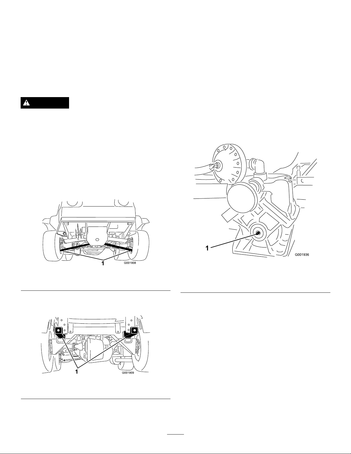
Premaintenance
Lubrication
Procedures
GreasingtheSprayer
JackingtheSprayer
Whenevertheengineisrunforroutinemaintenanceand/or
enginediagnostics,therearwheelsofthesprayershouldbe
1inch(25mm)offofthegroundwiththerearaxlesupported
onjackstands.
DANGER
Asprayeronajackmaybeunstableandslipoffof
thejack,injuringanyonebeneathit.
•Donotstarttheenginewhilethesprayerisona
jack.
•Alwaysremovethekeyfromtheignitionbefore
gettingoffofthesprayer.
•Blockthetireswhenthesprayerisonajack.
Thejackingpointatthefrontofthesprayerisunderthe
A-arms(Figure33)
ServiceInterval:Every50hours—Lubricatethepump.
Every100hours/Yearly(whichevercomes
rst)—Lubricateallgreasettings.
GreaseType:No.2GeneralPurposeLithiumBaseGrease
1.Wipethegreasettingcleansothatforeignmatter
cannotbeforcedintothebearingorbushing.
2.Pumpgreaseintothebearingorbushing.
3.Wipeoffexcessgrease.
Thegreasettingspositionsareillustratedbythe
following:Figure36throughFigure41.
Figure33
1.Frontjackingpoints
Thejackingpointattherearofthesprayerisontherear
framesupport,betweentheanglewelds(Figure34).
Figure34
1.Rearjackingpoints
Figure35
Pump(Donotovergrease)
1.Greasepoint
38
Page 39
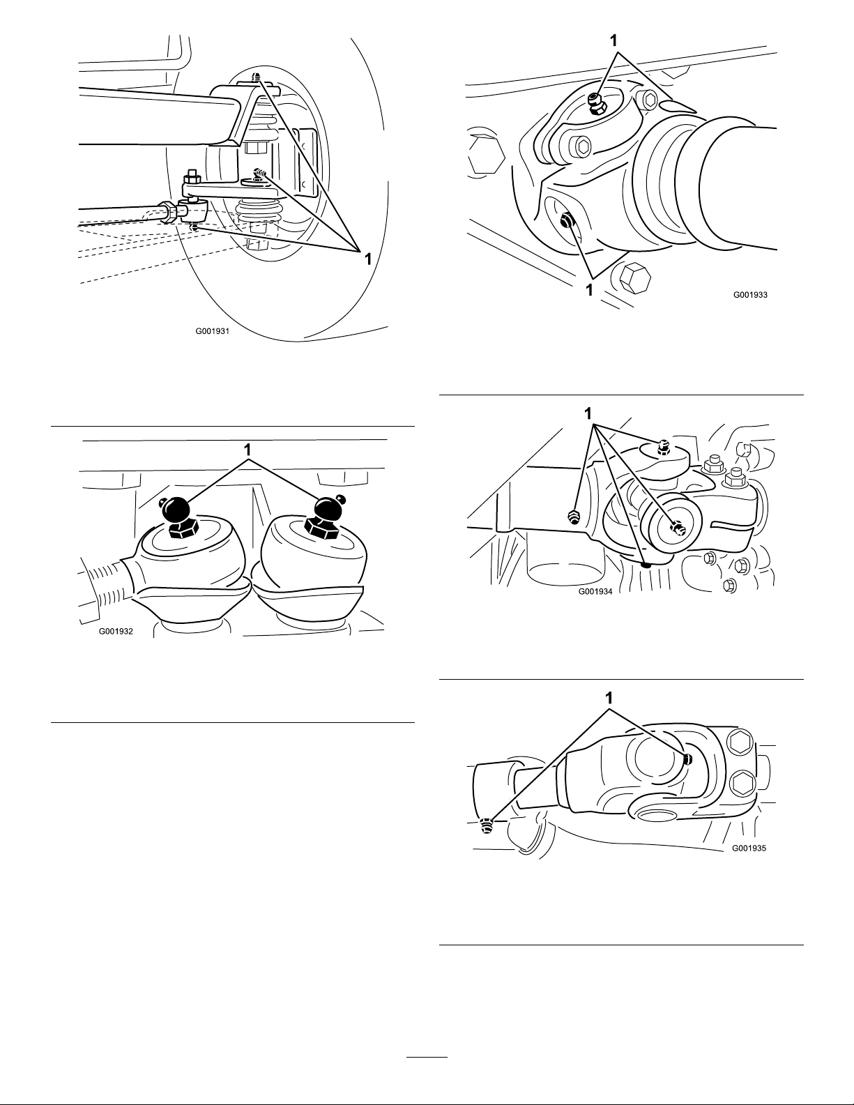
1.Greasepoint
1.Greasepoint
Figure36
Atthewheels,threeoneachside
Figure37
Steeringrods
Figure38
Pumpdrive,four,oneeachside
1.Greasepoint
Figure39
Driveaxelatengine,ve,oneeachsideandslipjoint
1.Greasepoint
39
Figure40
Driveaxelattransmission
1.Greasepoint
Page 40
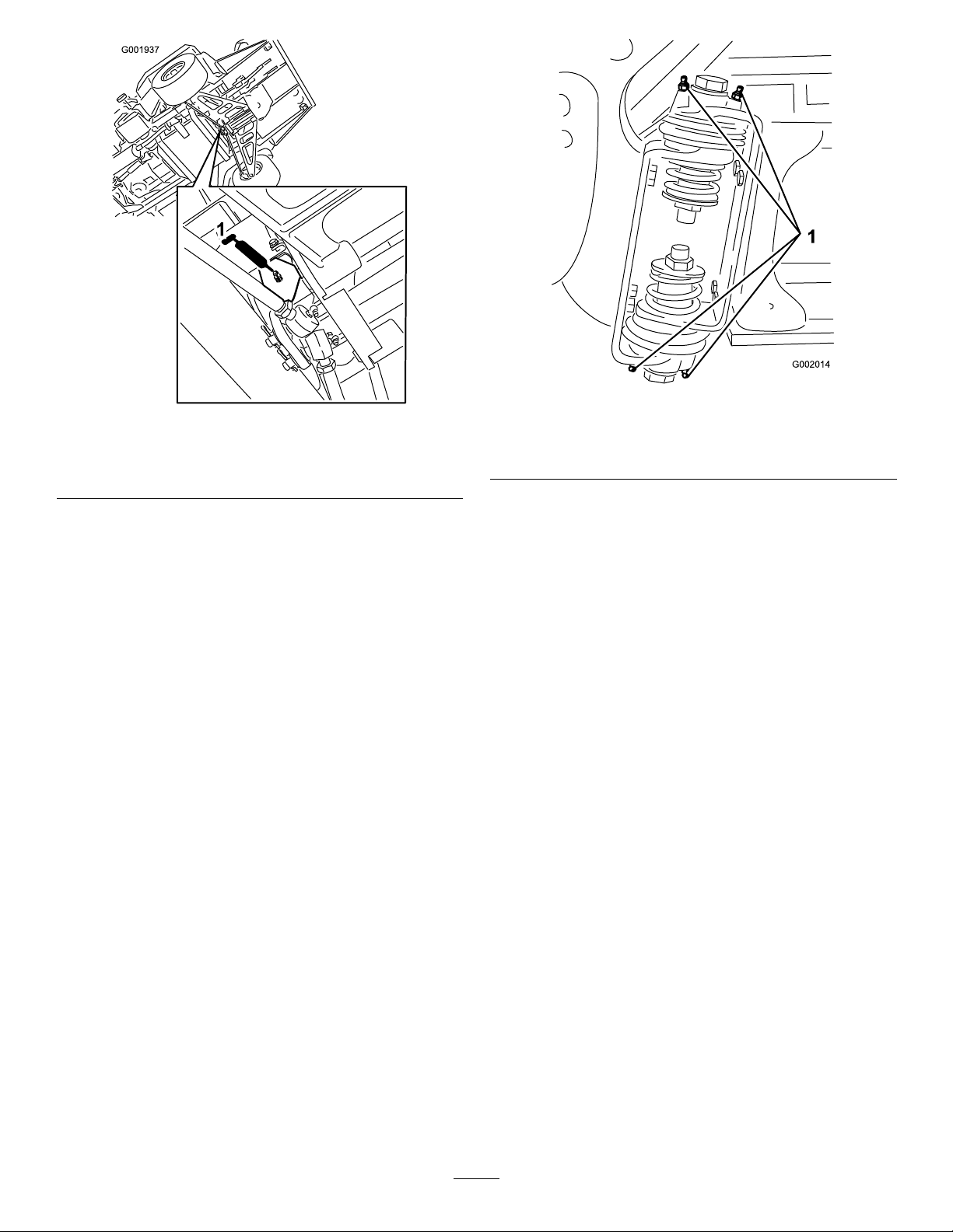
Steeringpivotabovesteeringrods
1.Greasepoint
GreasingtheBoomHinges
Figure41
Figure42
Rightboom
1.Greasetting
3.Wipeoffexcessgrease.
4.Repeattheprocedureforeachboompivot.
ServiceInterval:Every100hours
Important:Iftheboomhingeiswashedwithwater,
allwateranddebrismustbeclearedfromthehinge
assemblyandfreshgreasemustbeapplied.
GreaseType:No.2general-purposelithiumbasegrease.
1.Wipethegreasettingscleansothatforeignmatter
cannotbeforcedintothebearingorbushing.
2.Pumpgreaseintothebearingorbushingateachtting
Figure42.
GreasingtheActuatorRod Bearings
ServiceInterval:Every400hours/Y early(whichevercomes
rst)
GreaseType:No.2general-purposelithiumbasegrease.
1.Extendtheboomstothesprayposition.
2.Removethecotterpinfromthepivotpin(Figure43).
40
Page 41
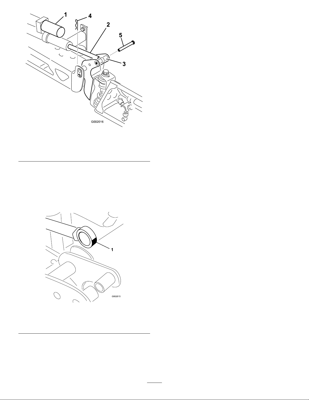
G002016
1
4
2
3
5
Figure43
8.Repeattheprocedureforeachactuatorrodbearing.
1.Actuator
2.Actuatorrod5.Pin
3.Boompivotpinhousing
4.Cotter
3.Liftupontheboomandremovethepin(Figure43).
Slowlylowertheboomtotheground.
4.Inspectthepinforanydamage,replaceifnecessary.
5.Manipulatetheactuatorrodbearingendandapply
greaseintothebearing(Figure44).Wipeoffexcess
grease.
Figure44
Rightboom
1.Greasebearing
6.Raisetheboomtoalignthepivotwiththeactuatorrod.
Whileholdingtheboom,insertthepinthroughboth
boompivotandactuatorrod(Figure43).
7.Withthepininplace,releasetheboomandsecurethe
pinwiththecotterremovedpreviously.
41
Page 42
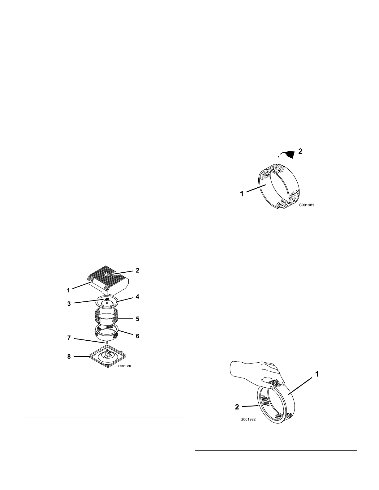
EngineMaintenance
6.Unscrewthecovernutandremovethecoverandpaper
element(Figure45).
CheckingtheAirIntakeScreen
ServiceInterval:Beforeeachuseordaily—Cleantheengine
rotatingscreen.
Every100hours—Cleantheenginerotatingscreen
(moreoftenindusty,dirtyconditions).
Checkandcleanasnecessarytheairintakescreenonthe
frontoftheengineevery8operatinghours.
ServicingtheAirCleaner
FoamElement:Cleanandoilafterevery25operatinghours,
oryearly,whicheveroccursrst.
PaperElement:Replaceafterevery100operatinghoursor
yearly,whicheveroccursrst.
Note:Servicetheaircleanermorefrequently(everyfew
hours)ifoperatingconditionsareextremelydustyorsandy.
RemovingtheFoamandPaper
Elements
1.Settheparkingbrake,stopthepump,stoptheengine,
andremovetheignitionkey.
2.Releasethelatchonthebackoftheseatandliftthe
seatforward.
3.Cleanaroundtheaircleanertopreventdirtfrom
gettingintotheengineandcausingdamage(
Figure45).
CleaningtheFoamElement
ServiceInterval:Every25hours/Yearly(whichevercomes
rst)—Cleanandoilthefoamaircleaner
(moreoftenindusty ,dirtyconditions).
1.Washthefoamelementinliquidsoapandwarmwater.
2.Whentheelementisclean,rinseitthoroughly.
3.Drytheelementbysqueezingitinacleancloth.
4.Putoneortwoouncesofoilontheelement(
Important:Replacethefoamelementifitistorn
orworn.
Figure46
1.Foamelement
5.Squeezetheelementtodistributetheoil.
2.Oil
Figure46).
CheckingthePaperElement
Figure45
1.Aircleanercover5.Foamelement
2.Knob6.Paperelement
3.Covernut
4.Cover
4.Loosentheknobontheaircleanercoverandremove
thecover(Figure45).
5.Carefullyslidethefoamelementoffthepaperelement
(Figure45).
7.Rubberseal
8.Aircleanerbase
ServiceInterval:Every100hours/Y early(whichevercomes
rst)—Replacethepaperaircleaner
element(moreoftenindusty,dirty
conditions).
Inspectthepaperelementfortears,anoilylm,damageto
therubberseal,excessivedirt,orotherdamage(Figure47).If
anyoftheseconditionsexit,replacethelter.
Important:Donotcleanthepaperelementwith
pressurizedairorliquids,suchassolvent,gas,or
kerosene.
Figure47
1.Paperelement2.Rubberseal
42
Page 43
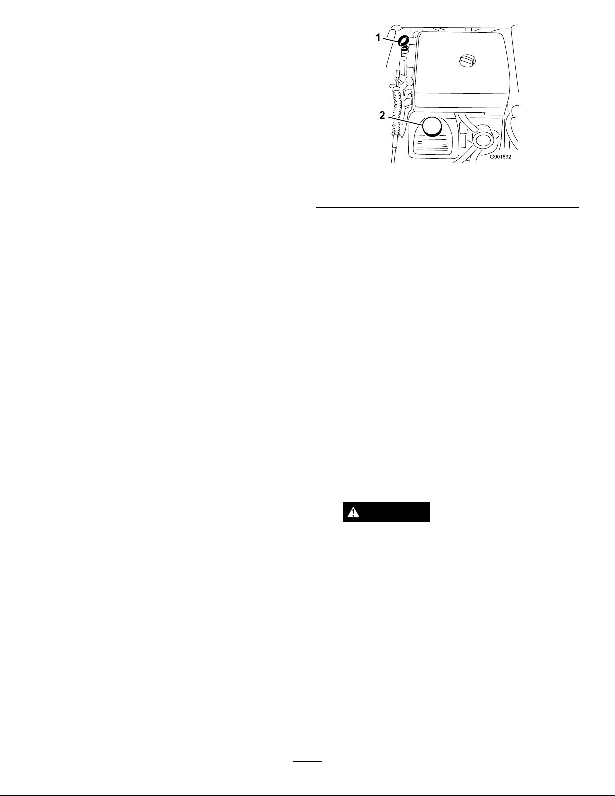
Important:T opreventenginedamage,alwaysoperate
theenginewiththecompletefoamandpaperaircleaner
assemblyinstalled.
InstallingtheFoamandPaperElements
1.Carefullyslidethefoamelementontothepaperair
cleanerelement(Figure45).
2.Slidetheaircleanerassemblyandcoverontothelong
rod.
3.Installthecovernutnger-tightagainstthecover
Figure45).
(
Note:Ensurethattherubbersealisatagainstthe
aircleanerbaseandcover.
4.Installtheaircleanercoverandknob(Figure45).
5.Closeandlatchtheseat.
ServicingtheEngineOil
CrankcaseCapacityis2.1qt(2.0l)withthelter.
Usehigh-qualityengineoilthatmeetsthefollowing
specications:
•APIclassicationLevelrequired:SJ,JK,SL,orhigher.
•Preferredoil:SAE10W30(above0°F)
•Alternateoil:SAE5W30(below32°F)
ToroPremiumEngineOilisavailablefromyourdistributor
ineither5W30or10W30viscosity .SeethePartsCatalogfor
partnumbers.
ChecktheEngineOil
ServiceInterval:Beforeeachuseordaily
Every400hours/Y early(whichevercomesrst)
Theengineisshippedwithoilinthecrankcase;however,the
levelofoilmustbecheckedbeforeyourststarttheengine
andafteryouhaverunit.
1.Positionthemachineonalevelsurface.
2.Removethedipstickandwipeitwithacleanrag
(Figure48).Insertthedipstickintothetubeandmake
sureitisseatedfully.Removethedipstickandcheck
theoillevel.
Figure48
1.Dipstick2.Fillercap
3.Iftheoillevelislow ,removethellercapfromthe
valvecover(Figure48)andpouroilintotheopening
untiltheoillevelisuptotheFullmarkonthedipstick.
Addtheoilslowlyandchecktheleveloftenduringthis
process.Donotoverll.
4.Installthedipstickrmlyinplace.
ChangingtheEngineOil
ServiceInterval:Aftertherst50hours—Changethe
engineoil.
Every100hours—Changetheengineoil,including
syntheticoil(moreoftenwhenoperatingunderheavy
loadorinhightemperature).
1.Starttheengineandletitrunforveminutes.This
warmstheoilsoitdrainsbetter.
2.Settheparkingbrake,stopthepump,stoptheengine,
andremovetheignitionkey.
3.Releasethelatchonthebackoftheseatandliftthe
seatforward.
CAUTION
Componentsundertheseatwillbehotifthe
sprayerhasbeenrunning.Ifyoutouchhot
componentsyoumaybeburned.
Allowthesprayertocoolbeforeperforming
maintenanceortouchingcomponentsunder
thehood.
4.Placeapanbelowtheoildrain.
5.Removethedrainplug(
43
Figure49).
Page 44
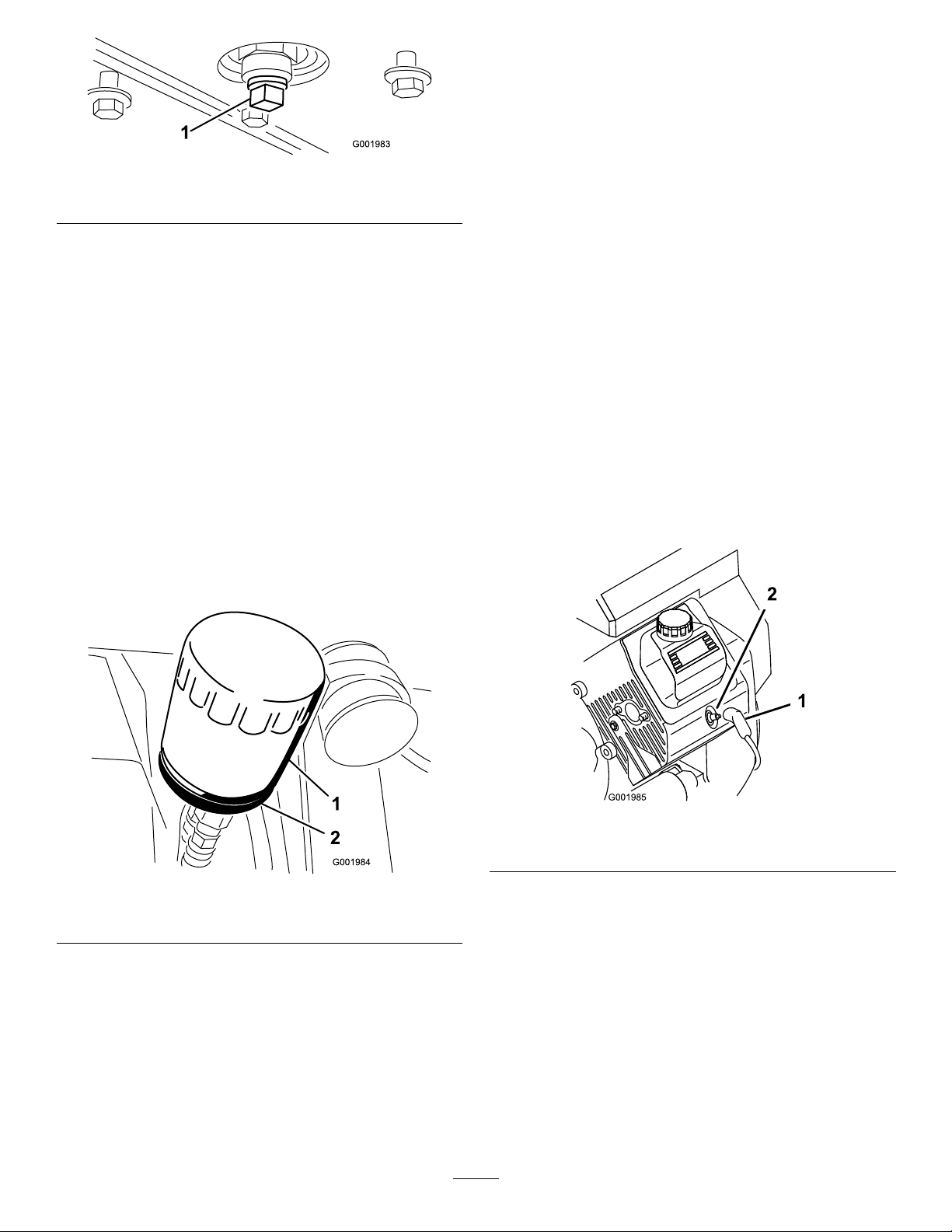
1.Oildrainplug
Figure49
7.Disposeoftheusedoillteratacertiedrecycling
center.
ChangingtheSparkPlugs
ServiceInterval:Every200hours
Type:ChampionRC-12YC(orequivalent)
AirGap:0.030inch(0.76mm)
6.Whentheoilhasdrainedcompletely ,replacethedrain
plugandtorqueitto10ft-lb(13.6N-m).
7.Disposeoftheusedoilatacertiedrecyclingcenter.
8.Slowlypourapproximately80%ofthespecied
amountofoilintotheoilllertube(
9.Checktheoillevel.
10.Slowlyaddadditionaloiltobringtheoilleveltothe
fullmarkonthedipstick.
Important:Overllingthecrankcasewithoilmay
causeenginedamage.
Figure48).
ChangingtheEngineOilFilter
ServiceInterval:Every100hours
1.Draintheoilfromtheengine;refertoChangingthe
EngineOil.
2.Removetheoillter(
Figure50).
Makesuretheairgapbetweenthecenterandsideelectrodes
iscorrectbeforeinstallingthesparkplugs.Useasparkplug
wrenchforremovingandinstallingthesparkplugsanda
gappingtool/feelergaugetocheckandadjusttheairgap.
RemovingtheSparkPlug
1.Settheparkingbrake,stopthepump,stoptheengine,
andremovetheignitionkey.
2.Releasethelatchonthebackoftheseatandliftthe
seatforward.
3.Pullthewiresoffthesparkplugs(
4.Cleanaroundthesparkplugstopreventdirtfrom
fallingintotheengineandpotentiallycausingdamage.
5.Removethesparkplugsandmetalwashers.
Figure51).
Figure50
1.Oillter
3.Wipethelteradaptergasketsurface.
4.Applyathincoatofnewoiltotherubbergasketon
thereplacementlter.
5.Installthereplacementoilltertothelteradapter.
Turntheoillterclockwiseuntiltherubbergasket
contactsthelteradapter,thentightenthelteran
additional1/2turn(Figure50).
6.Fillthecrankcasewiththecorrecttypeofnewoil;refer
toChangingtheEngineOil,steps8through10.
2.Filteradapter
Figure51
1.Sparkplugwire2.Sparkplug
CheckingtheSparkPlugs
1.Lookatthecenterofthesparkplugs(Figure52).
Ifyouseealightbrownorgraycoatingontheinsulator,
theengineisoperatingproperly.Ablackcoatingonthe
insulatorusuallymeanstheaircleanerisdirty.
Important:Donotcleanthesparkplugs.Always
replaceasparkplugwhenithasablackcoating,
wornelectrodes,anoilylm,orcracks.
2.Checkthegapbetweenthecenterandsideelectrodes
(
Figure52)andbendthesideelectrode,ifthegapis
notcorrect.
44
Page 45
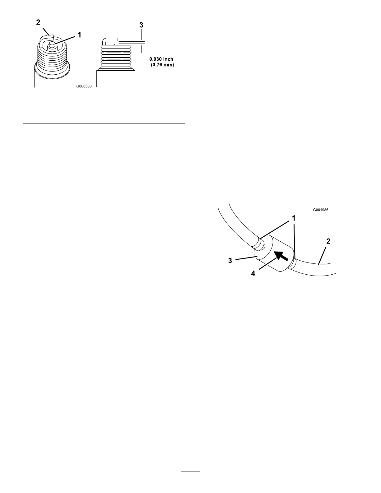
Figure52
1.Centerelectrodeinsulator3.Airgap(nottoscale)
2.Sideelectrode
FuelSystem
Maintenance
ReplacingtheFuelFilter
ServiceInterval:Every100hours—Replacethefuellter.
Every400hours/Yearly(whichevercomes
rst)—Inspectthefuellines.
1.Settheparkingbrake,stopthepump,stoptheengine,
andremovetheignitionkey.
2.Releasethelatchonthebackoftheseatandliftthe
seatforward.
InstallingtheSparkPlugs
1.Installthesparkplugsandmetalwashers.
2.Tightenthesparkplugsto18to22ft-lb(24.4to
29.8N-m).
3.Pushthewiresontothesparkplugs(Figure51).
4.Closeandlatchtheseat.
3.Clampoffthehoseoneithersideofthefuellterto
preventgasfrompouringoutofthehoseswhenyou
removethelter.
4.Placeadrainpanunderthelter.
5.Squeezetheendsofthehoseclampstogetherandslide
themawayfromthelter(
6.Removethelterfromthefuellines.
Figure53
1.Hoseclamp3.Filter
2.Fuelline4.Flowdirectionarrow
Figure53).
7.Installanewlterandmovethehoseclampscloseto
thelter.
Ensurethattheowdirectionarrowpointstoward
theengine.
DrainingtheFuelTank
ServiceInterval:Every400hours/Y early(whichevercomes
rst)
Drainandcleanthefueltankifthefuelsystembecomes
contaminatedorifyouplantostorethemachineforan
extendedperiod.Usefresh,cleanfueltoushoutthetank.
1.Transferthefuelfromthetankintoanapprovedfuel
containerusingasiphonpump,orremovethetank
fromthemachineandpourthefueloutofthetankll
spoutintothefuelcontainer.
45
Page 46
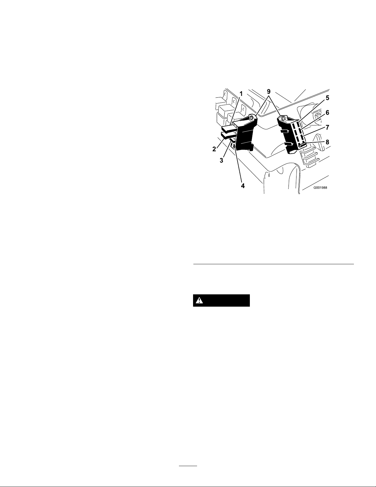
Note:Ifyouremovethefueltank,youwillneedto
removethefuelandreturnhosesfromthetankbefore
removingthetank.
2.Replacethefuellter;refertotheReplacingtheFuel
Filtersection.
3.Flushthetankwithfresh,cleanfuel,ifnecessary.
4.Installthetankifyouremoveditinstep1.
5.Fillthetankwithfresh,cleanfuel.
ElectricalSystem
Maintenance
ReplacingtheFuses
Thereare2fuseblocksand1emptyslotintheelectrical
system.Theyarelocatedbeneaththeseat(Figure54).
Figure54
1.Leftboomactuatorthermal
breaker
2.Rightboomactuator
thermalbreaker
3.Foammarker
4.Openslot
5.Power
6.Headlights
7.Cruisecontrol
8.Spraysystem
9.Fuseblocks
ServicingtheBattery
WARNING
CALIFORNIA
Proposition65Warning
Batteryposts,terminals,andrelatedaccessories
containleadandleadcompounds,chemicals
knowntotheStateofCaliforniatocausecancerand
reproductiveharm.Washhandsafterhandling.
Important:Donotjumpstartthesprayer.
Alwayskeepthebatterycleanandfullycharged.Useapaper
toweltocleanthebatteryandbatterybox.Ifthebattery
terminalsarecorroded,cleanthemwithasolutionoffour
partswaterandonepartbakingsoda.Applyalightcoatingof
greasetothebatteryterminalstopreventcorrosion.
Voltage:12voltwith280coldcrankingAmps@0°F
46
Page 47
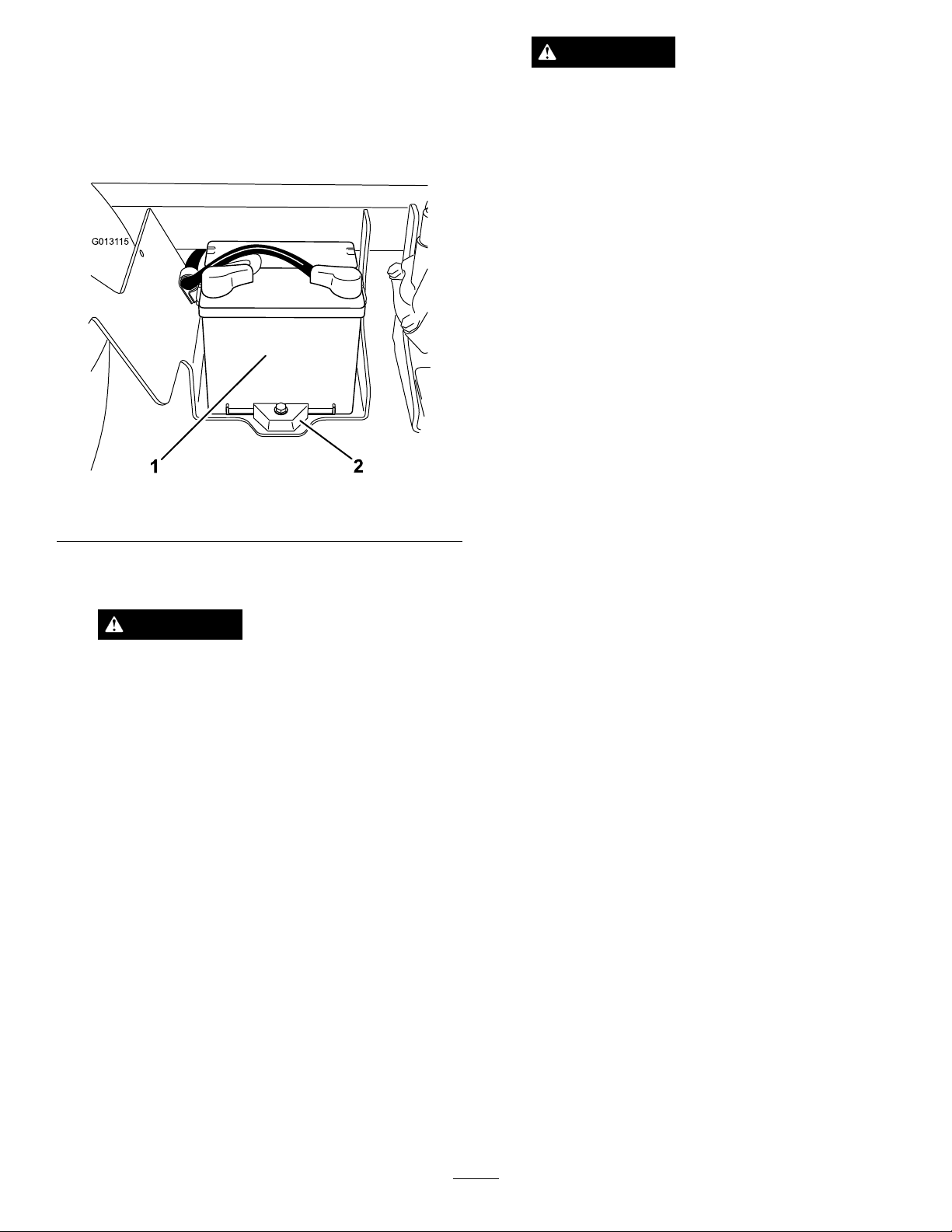
RemovingtheBattery
G0131 15
1
2
1.Positionthesprayeronalevelsurface,settheparking
brake,stopthepump,stoptheengine,andremovethe
ignitionkey.
2.Thebatteryislocatedontherighthandsideofthe
machinebehindthepump(Figure55).
WARNING
Batteryterminalsormetaltoolscouldshort
againstmetalsprayercomponentscausing
sparks.Sparkscancausethebatterygassesto
explode,resultinginpersonalinjury.
•Whenremovingorinstallingthebattery,
donotallowthebatteryterminalstotouch
anymetalpartsofthesprayer.
•Donotallowmetaltoolstoshortbetween
thebatteryterminalsandmetalpartsof
thesprayer.
•Alwayskeepthebatterystrapinplaceto
protectandsecurethebattery.
4.Disconnectthepositive(red)cablefromthebattery
post.
5.Removethebatteryretainerandfasteners(Figure55).
6.Removethebattery.
Figure55
1.Battery2.Retainer
3.Disconnectthenegative(black)groundcablefromthe
batterypost.
WARNING
Incorrectbatterycableroutingcoulddamage
thesprayerandcablescausingsparks.Sparks
cancausethebatterygassestoexplode,
resultinginpersonalinjury.
•Alwaysdisconnectthenegative(black)
batterycablebeforedisconnectingthe
positive(red)cable.
•Alwaysreconnectthepositive(red)battery
cablebeforereconnectingthenegative
(black)cable.
InstallingtheBattery
ServiceInterval:Every50hours—Checkthebatterycable
connections.
1.Setthebatteryonthebatteryboxsothatthebattery
postsaretowardthefrontofthesprayer.
2.Installthebatteryretainerandsecureitwiththe
fastenersyouremovedpreviously(
Important:Alwayskeepthebatteryretainerin
placetoprotectandsecurethebattery.
3.Connectthepositive(red)cabletothepositive(+)
batterypostandthenegative(black)cabletothe
negative(-)batterypostusingtheboltsandwingnuts.
Slidetherubberbootoverthepositivebatterypost.
4.Installthebatterycoverandsecureitwiththe2knobs
(Figure55).
Figure55).
CheckingtheElectrolyteLevel
ServiceInterval:Every50hours
Note:Whenthemachineisinstoragecheckthebattery
electrolytelevelevery30days.
1.Loosentheknobsonthesidesofthebatteryboxand
removethebatterycover(
2.Removethellercaps.Iftheelectrolyteisnotupto
thellline,addtherequiredamountofdistilledwater;
refertoAddingWatertotheBattery.
47
Figure55).
Page 48

DANGER
Batteryelectrolytecontainssulfuricacid
whichisadeadlypoisonandcausessevere
burns.
•Donotdrinkelectrolyteorallowitto
contactyourskin,eyesorclothing.Wear
safetyglassestoshieldyoureyesand
rubberglovestoprotectyourhands.
•Fillthebatterywherecleanwaterisalways
availableforushingtheskin.
AddingWatertotheBattery
Thebesttimetoadddistilledwatertothebatteryisjust
beforeyouoperatethemachine.Thisletsthewatermix
thoroughlywiththeelectrolytesolution.
1.Cleanthetopofthebatterywithapapertowel.
2.Removethellercapsfromthebatteryandslowlyll
eachcellwithdistilledwateruntilthelevelisuptothe
llline.Replacethellercaps.
themachine.Leavethecablesdisconnectedifitisstoredon
themachine.Storethebatteryinacoolatmospheretoavoid
quickdeteriorationofthechargeinthebattery.T oprevent
thebatteryfromfreezing,makesureitisfullycharged.
Important:Donotoverllthebattery.Electrolyte
willoverowontootherpartsofthesprayerand
severecorrosionanddeteriorationwillresult.
ChargingtheBattery
Important:Alwayskeepthebatteryfullycharged
(1.260specicgravity).Thisisespeciallyimportantto
preventbatterydamagewhenthetemperatureisbelow
32°F(0°C).
1.Removethebatteryfromthechassis;refertoRemoving
theBattery.
2.Checktheelectrolytelevel;refertoCheckingthe
ElectrolyteLevel.
3.Connecta3to4ampbatterychargertothebattery
posts.Chargethebatteryatarateof3to4amperesfor
4to8hours(12volts).Donotoverchargethebattery.
WARNING
Chargingthebatteryproducesgassesthatcan
explode.
Neversmokenearthebatteryandkeepsparks
andamesawayfrombattery.
4.Installthebatteryinthechassis;refertoInstallingthe
Battery.
StoringtheBattery
Ifthemachinewillbestoredformorethan30days,remove
thebatteryandchargeitfully .Eitherstoreitontheshelforon
48
Page 49
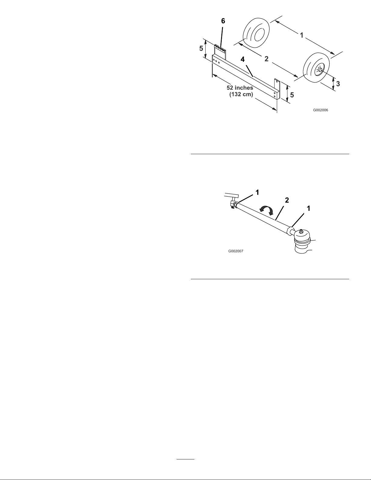
DriveSystem
Maintenance
InspectingtheWheels/Tires
ServiceInterval:Beforeeachuseordaily—Checkthetire
pressure.
Aftertherst8hours—Torquethewheellugnuts.
Every100hours—T orquethewheellugnuts.
Every100hours—Inspecttheconditionandwearof
thetires.
Figure56
Checkthetirepressureevery8hoursordailytoensure
properlevels.Fillthetiresto18psi(124kPa).Also,check
thetiresforwearordamage.
Checkthewheelstoensurethattheyaremountedsecurely
aftertherst8operatinghoursandthenevery100hours
thereafter.T orquethefrontboltsto50-55ft-lb(68-74N-m)
andtherearlugnutsto40-60ft-lb(54-81N-m).
Checkthetireconditionatleastevery100hoursofoperation.
Operatingaccidents,suchashittingcurbs,candamagea
tireorrimandalsodisruptwheelalignment,soinspecttire
conditionafteranaccident.
AdjustingtheFrontWheel Toe-In
ServiceInterval:Every100hours/Y early(whichevercomes
rst)
Thetoe-inshouldbe0to1/4inch(0to6mm).
1.Fillthetankwithapproximately80USgallons(303L)
ofwater.
1.Tirecenterline-back4.Fixture
2.Tirecenterline-front
3.Axlecenterline
5.Ifthemeasurementdoesnotfallwithinthespecied
range,loosenthejamnutsatbothendsofthetierods
(Figure57).
1.Jamnut2.Tierod
6.Rotatebothtierodstomovethefrontofthetire
inwardoroutward.
5.Axlecenterlinedistance
6.6inches(15cm)ruler
Figure57
2.Checkandllalltires;refertoCheckingTirePressure.
3.Drivethesprayerbackandforthafewtimestorelax
theA-arms,thendriveitforwardatleast10ft(3m).
4.Measurethedistancebetweenbothofthefronttires
attheaxleheightatboththefrontandrearofthe
fronttires(
neededfortherearmeasurementofthefronttiresat
axleheight.Usethesamextureoralignmentgaugeto
accuratelymeasurethefrontofthefronttiresataxle
height(Figure56).
Thefrontofthetiresshouldbe0to1/4inch(0to
6mm)closerthanthebacksideofthefronttires.
Figure56).Axtureoralignmentgaugeis
Note:Thetierodsshouldbethesamelengthwhen
youarenished.
7.Tightenthetierodjamnutswhentheadjustmentis
correct.
8.Ensurethatthereisfulltravelofthesteeringwheelin
bothdirections.
49
Page 50
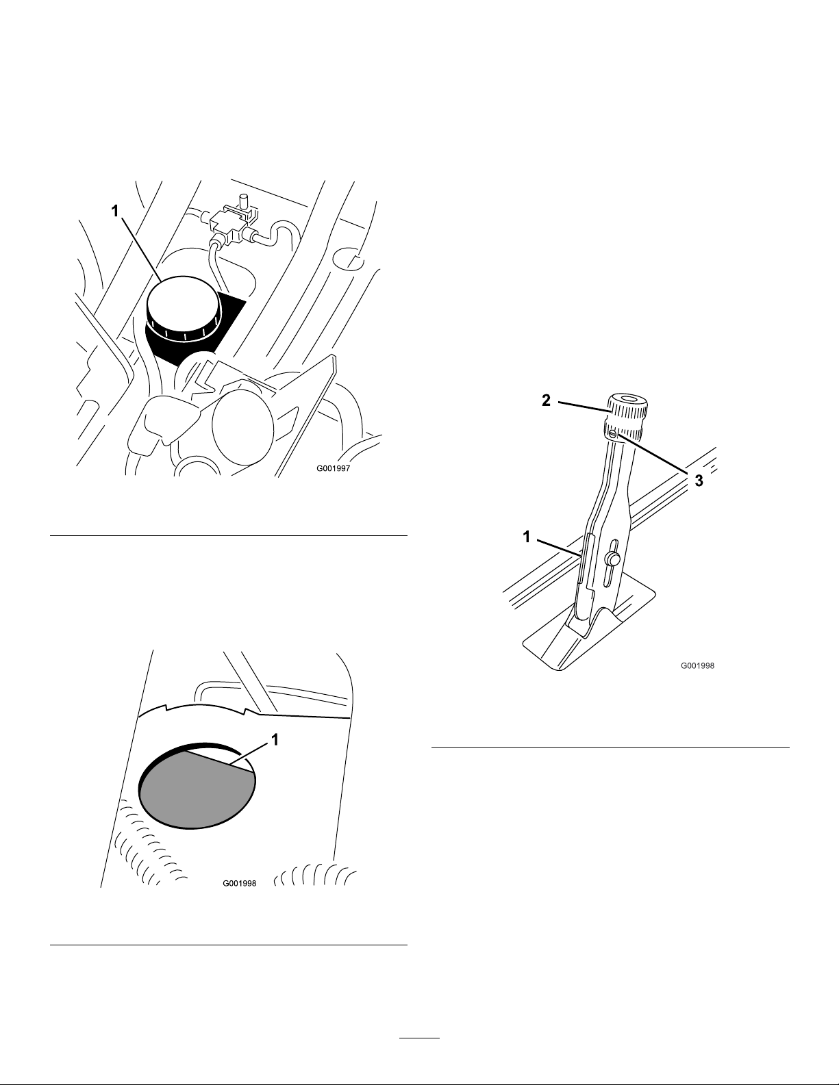
BrakeMaintenance
InspectingtheBrakes
ServiceInterval:Every100hours
CheckingtheBrakeFluid
Thebrakeuidreservoirisshippedfromthefactorylled
withDOT3brakeuid.Checkthelevelbeforestartingthe
engineeachday.
Figure58
Thebrakesareacriticalsafetycomponentofthesprayer.
Inspectthemasfollows:
•Inspectthebrakeshoesforwearordamage.Ifthelining
(brakepad)thicknessislessthan1/16inch(1.6mm),
replacethebrakeshoes.
•Inspectthebackingplateandothercomponentsforsigns
ofexcessivewearordeformation.Ifanydeformationis
found,replacetheappropriatecomponents.
AdjustingtheParkingBrake
ServiceInterval:Every200hours—Checktheparking
brake.
1.Loosenthesetscrewsecuringtheknobtotheparking
brakelever(Figure60).
1.Brakeuidreservoir
1.Positionthesprayeronalevelsurface,settheparking
brake,stopthepump,stoptheengine,andremovethe
ignitionkey.
2.TheuidlevelshouldbeuptotheFulllineonthe
reservoir(Figure59).
Figure59
Figure60
1.Parkingbrakelever
2.Knob
2.Rotatetheknobuntilaforceof35-45lbisrequired
toactuatelever.
3.Tightenthesetscrew .
3.Setscrew
1.Fullline
3.Iftheuidlevelislow,cleantheareaaroundthe
reservoircap,removethecap,andllthereservoirto
theproperlevel.Donotoverll.
50
Page 51
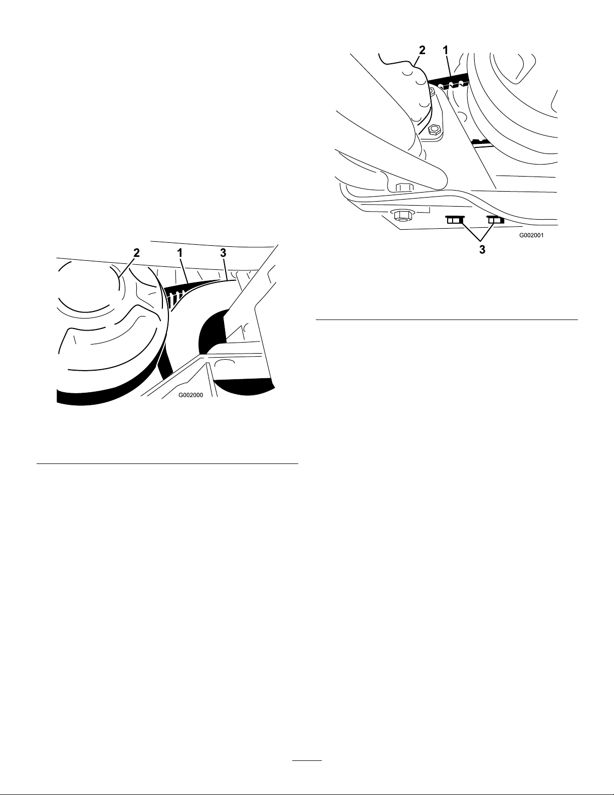
BeltMaintenance
ServicingtheDriveBelt
CheckingtheDriveBelt
ServiceInterval:Aftertherst8hours
Every200hours
1.Positionthesprayeronalevelsurface,settheparking
brake,movetherangeselectortotheNeutralposition,
stopthepump,stoptheengine,andremovethe
ignitionkey.
2.Rotateandinspectthedrivebeltforexcessivewearor
damage.Replacethebeltifnecessary.
2.Loosenthesteeringpumpmountingbolts(
Figure62
Figure62).
Figure61
1.Drivebelt
2.Primaryclutch
3.Secondaryclutch
ReplacingtheDriveBelt
1.Rotateandroutethebeltoverthesecondaryclutch
(Figure61).
2.Removethebeltfromtheprimaryclutch.
3.Placethenewbeltovertheprimaryclutch.
1.Steeringpumpbelt3.Steeringpumpmounting
bolts
2.Steeringpump
3.Movethepumpuntilthebeltexes1/4inch(5mm)
with5lb.offorce(22N)thentightenthemounting
bolts,startingwiththeboltclosesttotheengine
crankshaft.
4.Rotateandinstallitoverthesecondaryclutch.
AdjustingtheSteeringPump Belt
ServiceInterval:Aftertherst8hours
Every100hours
Thebeltshouldex1/4inch(5mm)when5lbofforce
(22N)isappliedmidwayonthetopspan.
1.Parkthemachineonalevelsurface,settheparking
brake,turntheignitionoff,andremovethekey .
51
Page 52
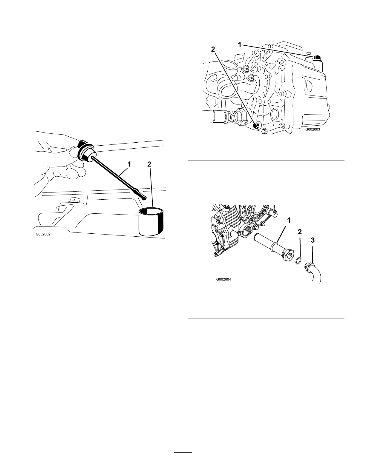
HydraulicSystem
Maintenance
Checkingthe Transaxle/HydraulicFluid
ServiceInterval:Every200hours
1.Positionthesprayeronalevelsurface,settheparking
brake,stopthepump,stoptheengine,andremovethe
ignitionkey.
2.Removethetransaxledipstickandwipeitwithaclean
rag(Figure63).
3.Removethedrainplugfromthesideofthereservoir
andletthehydraulicuidowintothedrainpan
(Figure64).
Figure64
1.Hydraulicdipstick2.Drainplug
4.Notetheorientationofthehydraulichoseand90
degreesttingconnectedtothestrainer.
5.Removethehydraulichoseand90degreestting
Figure65).
(
Figure63
1.Dipstick2.Fillhole
Important:Beverycarefulnottogetdirtorother
contaminantsintotheopeningwhencheckingthe
transmissionoil.
3.Insertthedipstickintothetubeandmakesureitis
seatedfully.Removethedipstickandchecktheoillevel.
4.Thetransaxleuidlevelshouldbeatthetopoftheat
portionofthedipstick.Ifitisnot,llthereservoir
withtheappropriateuid;refertoChangingthe
Transaxle/HydraulicFluid.
5.Installthedipstickrmlyinplace.
ChangingTransaxle/Hydraulic Fluid
ServiceInterval:Every800hours/Y early(whichevercomes
rst)
1.Positionthesprayeronalevelsurface,settheparking
brake,stopthepump,stoptheengine,andremovethe
ignitionkey.
2.Placeadrainpanunderthedrainplugofthereservoir.
Figure65
1.Hydraulicstrainer
2.O-ring
6.Removethestrainerandcleanitbybackushingit
withacleandegreaser.
7.Allowthestrainertoairdry.
8.Installthestrainerwhentheoilisdraining.
9.Installthehydraulichoseand90degreesttingtothe
strainer.
10.Installandtightenthedrainplug.
11.Fillthereservoirwithapproximately7.5qt.ofDexron
IIlATF .
Important:Useonlythehydraulicuids
specied.Otheruidscouldcausesystem
damage.
3.90degreestting
52
Page 53
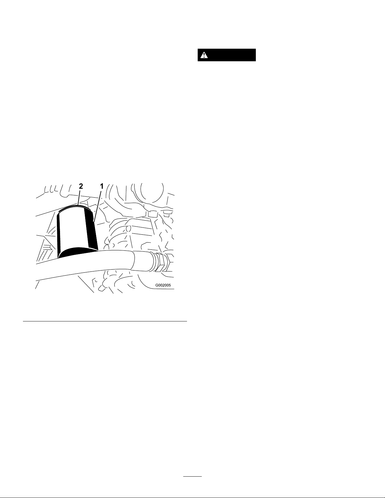
12.Starttheengineanddrivethesprayertollthe
hydraulicsystem.Rechecktheoillevelandreplenishit,
ifrequired.
SpraySystem Maintenance
ReplacingtheHydraulicFilter
ServiceInterval:Aftertherst8hours
Every800hours/Y early(whichevercomesrst)
UsetheT ororeplacementlter(PartNo.54-0110).
Important:Useofanyotherltermayvoidthewarranty
onsomecomponents.
1.Positionthesprayeronalevelsurface,settheparking
brake,stopthepump,stoptheengine,andremovethe
ignitionkey.
2.Cleantheareaaroundtheltermountingarea.
3.Placeadrainpanunderthelter.
4.Removethelter(
Figure66).
WARNING
Chemical substances used in the spray system may
be hazardous and to xic to y ou, bystander s, animals,
plants, soils or other pr oper ty .
•Carefullyreadandfollowthechemical
warninglabelsandMaterialSafetyData
Sheets(MSDS)forallchemicalsusedand
protectyourselfaccordingtothechemical
manufacturer'srecommendations.Forexample,
useappropriatePersonalProtectiveEquipment
(PPE)includingfaceandeyeprotection,gloves,
orotherequipmenttoguardagainstpersonal
contactwiththechemical.
•Keepinmindthattheremaybemorethanone
chemicalusedandinformationoneachshould
beassessed.
R efuse to operate or w or k on the spray er if this
•
inf or mation is not a v aila ble!
•Beforeworkingonaspraysystemmakesurethe
systemhasbeentriplerinsedandneutralized
accordingtotherecommendationsofthe
chemicalmanufacturer(s).
Figure66
1.Hydrauliclter2.Gasket
5.Lubricatethenewltergasket.
6.Ensurethattheltermountingareaisclean.
7.Screwthelteronuntilthegasketcontactsthe
mountingplate,thentightenthelterone-halfturn.
8.Starttheengineandletitrunforabouttwominutesto
purgeairfromthesystem.Stoptheengineandcheck
thehydraulicoillevelandforleaks.
•Verifythereisanadequatesupplyofcleanwater
andsoapnearby,andimmediatelywashoffany
chemicalsthatcontactyou.
InspectingtheHoses
ServiceInterval:Every200hours—Inspectallhosesand
connectionsfordamageandproper
attachment.
Examineeachhoseinthespraysystemforcracks,leaksor
otherdamage.Atthesametime,inspecttheconnectionsand
ttingsforsimilardamage.Replaceanyhosesandttingsif
damaged.
53
Page 54
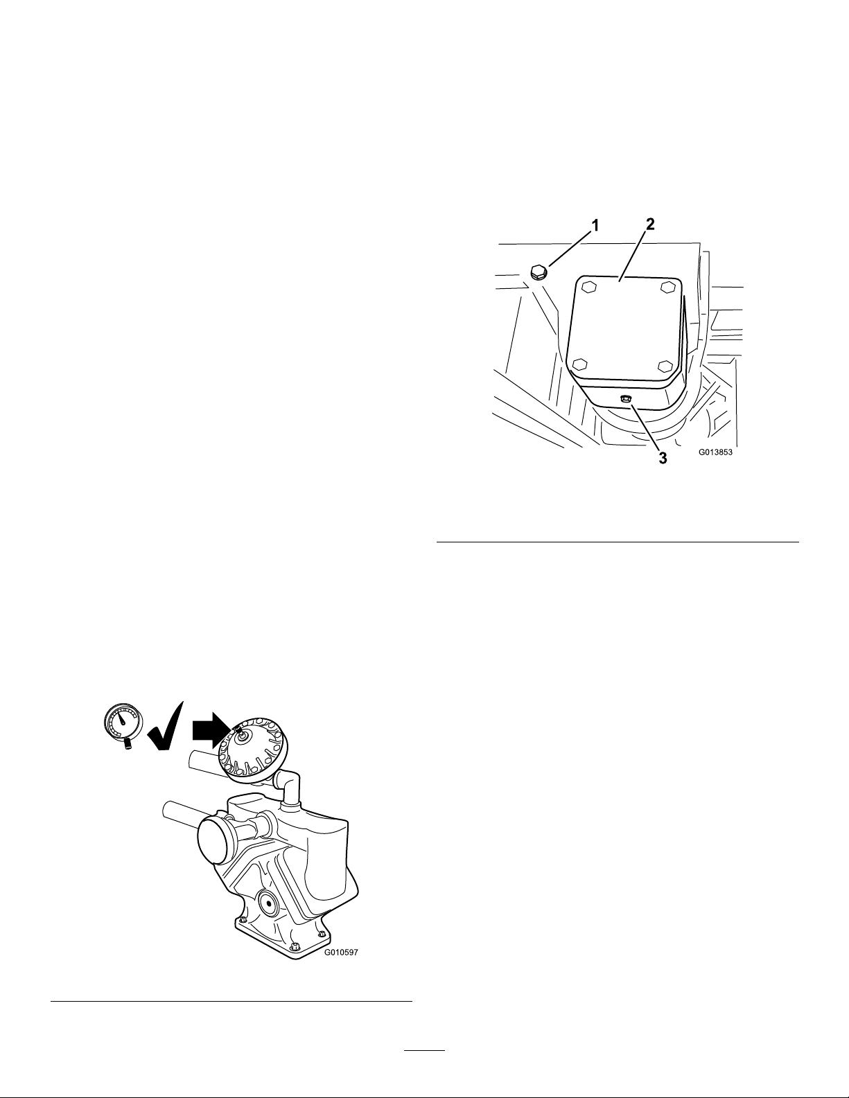
PumpMaintenance
G010597
G013853
1
2
3
ChangingthePumpDriveGearbox
Fluid
InspectingthePump
ServiceInterval:Every400hours/Y early(whichevercomes
rst)—Inspectthepumpdiaphragmand
replaceifnecessary.(seeanAuthorized
ToroServiceDistributor)
Every400hours/Yearly(whichevercomes
rst)—Inspectthepressuredampenerbladderand
replaceifnecessary.(seeanAuthorizedToroService
Distributor)
Every400hours/Yearly(whichevercomes
rst)—Inspectthepumpcheckvalvesandreplace
ifnecessary.(seeanAuthorizedT oroService
Distributor)
Note:Thefollowingmachinecomponentsareconsidered
partssubjecttoconsumptionthroughuseunlessfound
defectiveandarenotcoveredbytheW arrantyassociatedwith
thismachine.
HaveanAuthorizedToroServiceDistributorcheckfollowing
internalpumpcomponentsfordamage:
•Pumpdiaphragm
•Pressuredampenerbladder
•Pumpcheckvalvesassemblies
Replaceanycomponentsifnecessary.
AdjustingtheAirPressureinDampener
Theairpressureinthedampeneronthepumpissetat15psi
(1bar)bythemanufacturer.Therecommendedpressurein
thedampeneris1/3ofthesprayingpressure.Ifusingaspray
pressuregreaterthan45psi(3.1bar)adjustthedampener
accordingly.
ServiceInterval:Every400hours/Y early(whichevercomes
rst)
1.Positionthesprayeronalevelsurface,settheparking
brake,stopthepump,stoptheengine,andremovethe
ignitionkey.
2.Placeapanunderthedrainplugonthepumpdrive
gearbox(Figure68).
Figure68
1.Fill-levelplug3.Drainplug
2.Filltube
3.Removethell-levelpluganddrainplug(Figure68),
allowingtheoiltodrainintothepan.
4.Installandtightenthedrainplugwhentheuidstops
draining.
5.Locategearboxvent/llhoseextendingupfromthe
gearbox.Removethecapfromthehose.
6.Addapproximately18-20ouncesofMobilSHC634
SyntheticLubricanttothelltubeoruntilthegear
lubricantbeginstoowoutofthell-levelport.
Important:UseonlyMobilSHC634Synthetic
Lubricantorequivalentsyntheticuidinthegear
box.Non-syntheticoilsmaybreakdowncausing
damagetothepumpgearbox.
7.Installthell-levelplugandvent/llhosecap.
Figure67
AdjustingtheBoomActuator
ServiceInterval:Every400hours—Checkboomactuator
hydraulicoilforairbubbles.
1.Positionthesprayeronalevelsurface,lowerthebooms
intothesprayposition.
2.Settheparkingbrake,stopthepump,stoptheengine,
andremovetheignitionkey
3.Attempttolifttheboombyapplyingamoderate
amountofpressure(justenoughtolifttheboom
54
Page 55
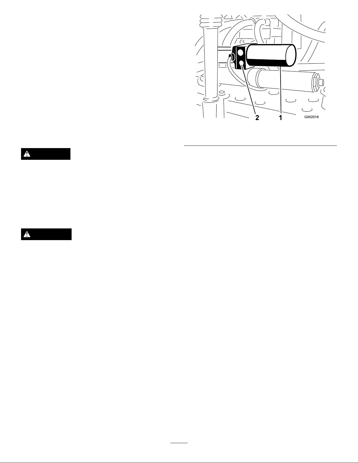
manually)whileobservingtheactuatorrod.Ifthe
actuatorrodexhibitsmovementrefertobelow .
4.Repeattheprocedurefortheopposingboom.
Iftheactuatorrodexhibitsanaxialmovement(travelsintoor
outofthecylinder)greaterthan0.085-0.100inch(2.16-2.54
mm),youmaywishtobleedtheairfromthehydraulicoil.
RefertotheServiceManualforinstructionsonhowtobleed
airfromtheactuatorsorcontactanAuthorizedToroService
Distributor.
EmergencyManualOperation oftheBoomActuators
Note:Determinetheleftandrightsidesofthemachine
fromthenormaloperatingposition.
DANGER
Useofthemanualreliefvalvemaycausetheboom
tomovesuddenlyandcauseinjurytoyouorothers.
•Takecautionandadjustthemanualreliefvalve
slowly.
•Ensurethesurroundingareaisclearandnoone
isinsidetheoperatingrangeoftheboom.
CAUTION
Adjustingthemanualreliefvalvewithelectrical
powerpresentcouldcausetheactuatoroperate
irregularlyandcauseinjurytoyouorothers.
Do not
powerisbeingsuppliedtotheactuator.
Incaseofanemergencysuchthattheboommustbemoved
andno12VDCpowersourceisavailable,themanualrelief
valvecanbeusedtorelievepressurewithintheactuatorand
allowtheboomstobemovedmanually.
usethemanualreliefvalvewhileelectrical
Figure69
1.Actuator,rightboom
Note:Duetotheopposingorientationofactuatorsin
respecttoeachotherthemanualreliefvalveisonthe
forwardfaceoftheleftboomactuatorandtherear
faceoftherightboomactuator.
2.Useahexagonalwrenchtoloosenthemanualrelief
valvenomorethan2-3turns.Thecylindershouldstart
strokingmanuallyorbyexternalpressureatthistime.
3.Oncetheoriginalpositionoftheactuatorisrecovered,
closethemanualreliefvalve.Torquethevalveto
1.1-2.1ft-lb(1.5-2.9N-m).
2.Manualreliefvalve
InspectingtheNylonPivot Bushings
ServiceInterval:Every400hours/Y early(whichevercomes
rst)
1.Positionthesprayeronalevelsurface,settheparking
brake,stopthepump,stoptheengine,andremovethe
ignitionkey.
2.Extendtheboomstothespraypositionandsupport
theboomsusingstandsorstrapsfromalift.
Important:Themanualvalvemustnotbeloosened
morethan4turns.Turningthevalvemorethan4turns
maycausethevalvetocomeoffcompletelyallowing
hydraulicoiltospillout.
1.Locatethemanualreliefvalveontheactuatorforeach
boom.Themanualreliefvalveisthesmallervalveand
isonlyononesideoftheactuatorbody(
Figure69).
3.Withtheweightoftheboomsupported,remove
theboltandnutsecuringthepivotpintotheboom
assembly(
55
Figure70).Removethepivotpin.
Page 56
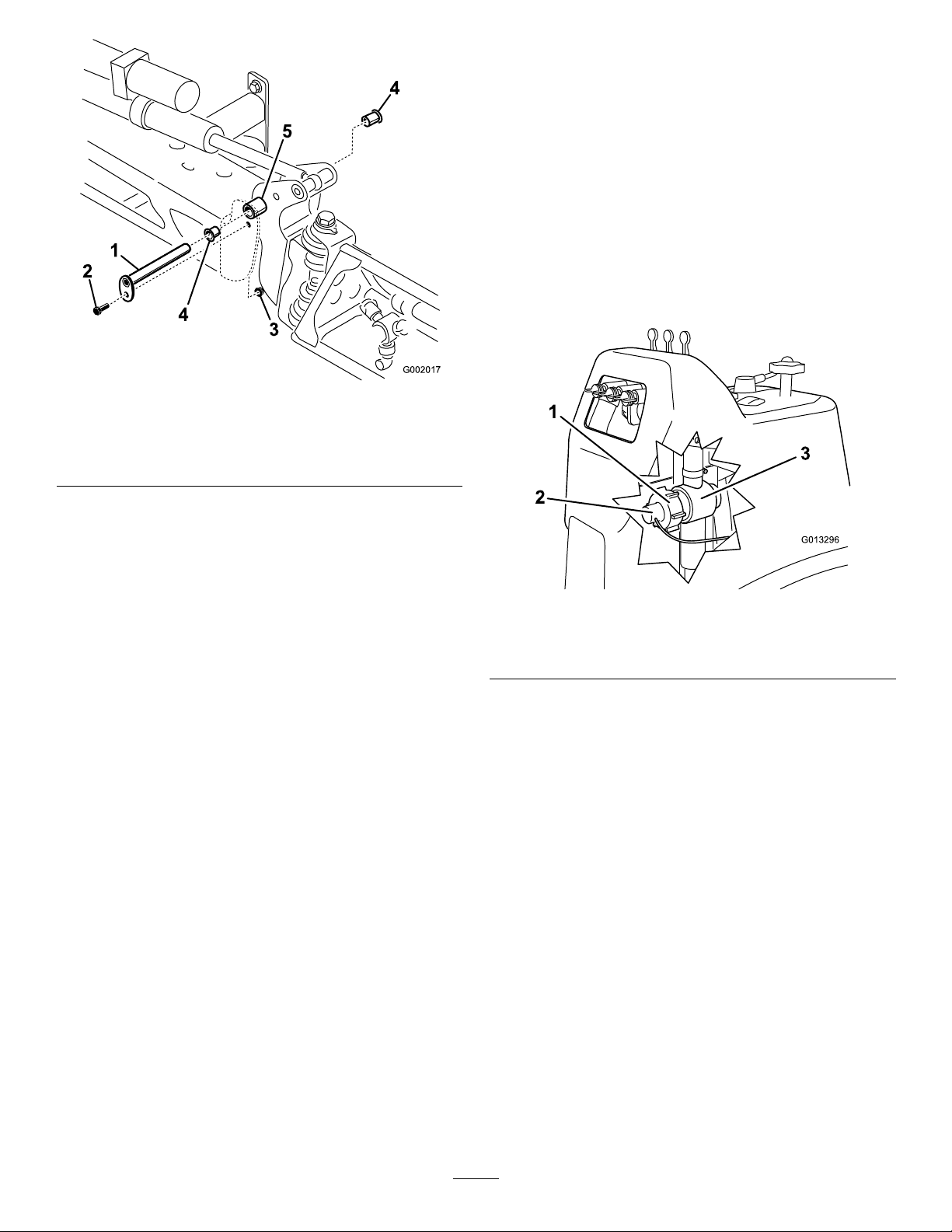
G002017
2
3
1
4
4
5
Figure70
G013296
1
2
3
1.Pivotpin4.Nylonbushing
2.Bolt5.Pivotbracket
3.Nut
Cleaning
CleaningtheFlowmeter
ServiceInterval:Every200hours/Y early(whichevercomes
rst)(Moreoftenwhenusingwettable
powders)
Theowmetermayneedtobecleanedtoremovean
obstruction.asfollows:
1.Thoroughlyrinseanddraintheentiresprayingsystem.
2.Removetheretainingcapfromtheowmeterbody
(Figure71).
4.Removetheboomandpivotbracketassemblyfrom
thecenterframetoaccessthenylonbushings.
5.Removeandinspectthenylonbushingsfromthefront
andbacksidesofthepivotbracket(Figure70).Replace
anydamagedbushings.
6.Placeasmallamountofoilonthenylonbushingsand
installthemintopivotbracket.
7.Installtheboomandpivotbracketassemblyintothe
centerframe,aligningtheopenings(
8.Installthepivotpinandsecureitwiththeboltandnut
removedpreviously.
Repeattheprocedureforeachboom.
Figure70).
Figure71
1.Retainingcap3.Flowmeterbody
2.Paddlewheelassembly
3.Carefullypullthepaddlewheelassemblyfromthebody .
4.Usewarmwater,asoft-bristledbrush,andamild
detergentasnecessarytocleantheowmeterbodyand
paddlewheel.Removeanysmallmetallicdebris.
Important:Donotusesolventsorfueltoclean
theowmeter.
5.Installthepaddlewheelassemblyintotheowmeter
body.
Important:Thepaddlewheelassemblywill
onlytintothebodyoneway .Alignthepinof
thepaddlewheelassemblywiththeholeinthe
owmeterbody.Donotforcethepaddlewheel
assemblyintothebodyinanyotherorientation.
6.Installtheretainingcap.
7.Calibratetheowmeterusing
theproceduredescribedinthe
CalibratingtheSprayProMonitor(page31)section
inOperation.
56
Page 57
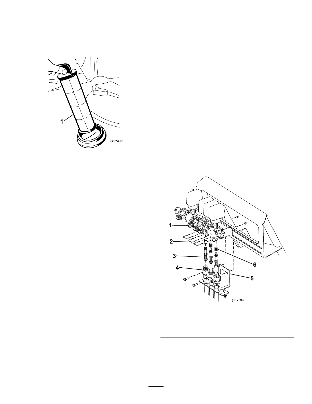
CleaningtheSuctionStrainer
g017893
1
2
3
4
5
6
ServiceInterval:Beforeeachuseordaily(moreoftenwhen
usingwetablepowders)
1.Removetheretainerfromtheredttingattachedto
thelargehoseonthetopofthetank.
Storage
1.Positionthesprayeronalevelsurface,settheparking
brake,stopthepump,stoptheengine,andremovethe
ignitionkey.
2.Cleandirtandgrimefromtheentiremachine,including
theoutsideoftheengine'scylinderheadnsand
blowerhousing.
Important:Y oucanwashthemachinewithmild
detergentandwater.
w ater
towashthemachine.Pressurewashing
maydamagetheelectricalsystemorwashaway
necessarygreaseatfrictionpoints.Avoidexcessive
useofwater,especiallynearthecontrolpanel,
lights,engine,andthebattery.
3.Cleanthespraysystem;refertotheCleaningsection.
4.Cleanthepistonsinthevalveassemblyasfollows:
A.PositionthevalvesintheOFFposition(shaft
closetothehosebarb).
Do not
use
high pr essur e
Figure72
1.Suctionstrainer
2.Disconnectthehosefromthetank.
3.Pullthestraineroutofthehole.
4.Cleanthestrainerwithcleanrunningwater.
5.Replacethestrainer,seatingitfullyintothehole.
6.Connectthehosetothetopofthetankandsecure
itwiththeretainer.
Note:Makesurethereisnowaterinthetubing.
B.Removethe3forkssecuringthevalveseatstothe
valveassembly(
Figure73).
Figure73
1.Valveassembly4.Valveseat
2.Fork5.Hoseloombracket
3.Valvepiston
C.Removethe2screwsandnutssecuringthehose
loombrackettothesprayerframe(Figure73).
Lowerthehosesawayfromthevalveassembly.
D.Usinga3mmAllenwrench,removethescrews
securingthepistonassembliesinthevalve
6.Spring
57
Page 58

assembly.Makesuretoaccountforthesprings
inthevalve(Figure73).
E.CleanthepistonsandreplaceanywornO-rings.
F.CoatallpistonO-ringswithvegetableoiland
reinstallinthevalveassemblywiththescrews
previouslyremoved.Makesuretoinstallthe
springsintothevalveassembly.
G.Securethevalveseatstothevalveassemblywith
the3forkspreviouslyremoved.
50daysattemperatureslowerthan40degreesF(4
degreesC).Ifthetemperatureswillbeabove40
degreesF(4degreesC),checkthewaterlevelin
thebatteryandchargeitevery30days.
15.Checkandtightenallbolts,nuts,andscrews.Repairor
replaceanypartthatisdamaged.
16.Checktheconditionofallsprayhoses,replacingany
thataredamagedorworn.
17.Tightenallhosettings.
H.Mountthehoseloombrackettothesprayerframe
withthe2screwsandnutspreviouslyremoved.
5.Addarustinhibiting,non-alcoholbased,RVantifreeze
solutiontothesystemandrunthepumpforafew
minutestocirculateitthroughthesystem,thendrain
thespraysystemascompletelyaspossible.
6.Usetheboomliftswitchestoraisethebooms.Raise
theboomsuntilhavemovedcompletelyintoboom
transportcradleformingthe“X”transportposition
andtheboomcylindersarefullyretracted.Make
suretheboomcylindersarefullyretractedtoprevent
actuatorroddamage.
7.Inspectthebrakes;refertoInspectingtheBrakesinthe
BrakeMaintenancesection.
8.Servicetheaircleaner;refertoServicingtheAir
CleanerintheEngineMaintenancesection.
9.Greasethesprayer;refertotheLubricationsection.
10.Changethecrankcaseoil;refertoServicingEngineOil
intheEngineMaintenancesection.
11.Checkthetirepressure;refertoCheckingtheTire
PressureintheDriveSystemMaintenancesection.
18.Paintallscratchedorbaremetalsurfaces.
PaintisavailablefromyourAuthorizedServiceDealer.
19.Storethemachineinaclean,drygarageorstoragearea.
20.Removetheignitionkeyandputitinasafeplaceout
ofthereachofchildren.
21.Coverthemachinetoprotectitandkeepitclean.
12.Forstorageover30days,preparethefuelsystemas
follows:
A.Starttheengineandrunitatidlespeedfor
approximately2minutes.
B.Stoptheengine.
C.Flushthefueltankwithfresh,cleanfuel.
D.Secureallthefuelsystemttings.
13.Usetheelectricstartertocranktheengineand
distributetheoilinsidethecylinder.
14.Removethebatteryfromthechassis,checkthe
electrolytelevel,andchargeitfully;refertoServicing
theBatteryintheElectricalSystemMaintenance
section.
Note:Donotconnectthebatterycablestothebattery
postsduringstorage.
Important:Thebatterymustbefullychargedto
preventitfromfreezingandbeingdamagedat
temperaturesbelow32degreesF(0degreesC).A
fullychargedbatterymaintainsitschargeforabout
58
Page 59

Troubleshooting
TroubleshootingtheEngineandVehicle
Problem
Thestarterdoesnotcrank.
Theenginecranks,butwillnotstart.
Theenginestarts,butdoesnotkeep
running.
PossibleCauseCorrectiveAction
1.Therangeselectorisinagearother
thanNeutral.
2.Theelectricalconnectionsarecorroded
orloose.
3.Afuseisblownorloose.3.Correctorreplacefuse.
4.Thebatteryisdischarged.
5.Thesafetyinterlocksystemis
malfunctioning.
6.Abrokenstarterorstartersolenoid.
7.Seizedinternalenginecomponents.7.ContactyourAuthorizedService
1.Thefueltankisempty.1.Fillwithfreshfuel.
2.Dirt,water,orstalefuelisinthefuel
system.
3.Cloggedfuelline.3.Cleanorreplace.
4.Thesparkplugleadisdisconnected.4.Reconnectthesparkplug.
5.Asparkplugisdamagedordirty.5.Replacethesparkplug.
6.Thekillrelayisnotenergized.
7.Theignitionisbroken.
1.Thefueltankventisrestricted.1.Replacethefuelcap.
2.Dirtorwaterinthefuelsystem.2.Drainandushthefuelsystem;add
3.Thefuellterisclogged.3.Replacethefuellter.
4.Afuseisblownorloose.4.Correctorreplacefuse.
5.Thefuelpumpisbroken.5.ContactyourAuthorizedService
6.Thecarburetorisbroken.
7.Loosewiresorpoorconnections.
8.Thecylinderheadgasketisbroken.
1.Pressthebrakepedalandmovethe
rangeselectortotheNeutralposition.
2.Checktheelectricalconnectionsfor
goodcontact.
4.Chargeorreplacethebattery .
5.ContactyourAuthorizedService
Dealer.
6.ContactyourAuthorizedService
Dealer.
Dealer.
2.Drainandushthefuelsystem;add
freshfuel.
6.ContactyourAuthorizedService
Dealer.
7.ContactyourAuthorizedService
Dealer.
freshfuel.
Dealer.
6.ContactyourAuthorizedService
Dealer.
7.Checkandtightenwireconnections.
8.ContactyourAuthorizedService
Dealer.
Theengineruns,butknocksormisses.
1.Dirt,water,orstalefuelisinthefuel
system.
2.Asparkplugleadisloose.2.Reconnectthesparkpluglead.
3.Asparkplugisbroken.3.Replacethesparkplug.
4.Loosewiresorpoorconnections.
5.Engineoverheating.
1.Drainandushthefuelsystem;add
freshfuel.
4.Checkandtightenwireconnections.
5.SeeEngineOverheats.
59
Page 60

Problem
PossibleCauseCorrectiveAction
Theenginewillnotidle.
Theengineoverheats.
Theenginelosespower .
1.Thefueltankventisrestricted.1.Replacethefuelcap.
2.Dirt,water,orstalefuelisinthefuel
system.
3.Asparkplugisdamagedorbroken.3.Replacethesparkplug.
4.Carburetoridlepassagesareplugged.4.ContactyourAuthorizedService
5.Theidlespeedadjustingscrewis
incorrectlyset.
6.Thefuelpumpisbroken.6.ContactyourAuthorizedService
7.Lowcompression.
8.Theaircleanerelementisdirty.
1.Thecrankcaseoillevelisincorrect.
2.Excessiveloading.2.Reduceload;uselowergroundspeed.
3.Theairintakescreensaredirty.
4.Thecoolingnsandairpassages
undertheengineblowerhousing
and/ortherotatingairintakescreenare
plugged.
5.Thefuelmixtureislean.5.ContactyourAuthorizedService
1.Thecrankcaseoillevelisincorrect.
2.Theaircleanerelementisdirty.
3.Dirt,water,orstalefuelisinthefuel
system.
4.Theengineisoverheated.
5.Asparkplugisdamagedordirty.5.Replacethesparkplug.
6.Theventholeinthefueltankvent
ttingisplugged.
7.Lowcompression.
2.Drainandushthefuelsystem;add
freshfuel.
Dealer.
5.ContactyourAuthorizedService
Dealer.
Dealer.
7.ContactyourAuthorizedService
Dealer.
8.Cleanorreplace.
1.Fillordraintothefullmark.
3.Cleanwitheveryuse.
4.Cleanwitheveryuse.
Dealer.
1.Fillordraintothefullmark.
2.Cleanorreplace.
3.Drainandushthefuelsystem;add
freshfuel.
4.SeeEngineOverheats.
6.Replacethefuelcap.
7.ContactyourAuthorizedService
Dealer.
Themachinewillnotoperateorissluggish
ineitherdirectionbecausetheengine
bogsdownorstalls.
Themachinewillnotoperateineither
direction.
1.Theenginemountingboltsareloose.1.Tightentheenginemountingbolts. Abnormalvibrationornoise.
2.Thereisaproblemwiththeengine.
1.Theparkingbrakeisset.1.Releasetheparkingbrake.
1.TherangeselectorisintheNeutral
position.
2.Theparkingbrakewasnotreleasedor
theparkingbrakeisnotreleasing.
3.Thetransmissionisbroken.
4.Thecontrollinkageneedsadjustment
orreplacement.
5.Thedriveshaftorwheelhubkeyhas
beendamaged.
2.ContactyourAuthorizedService
Dealer.
1.Pressthebrakeandshifttherange
selectorintoagear.
2.Releasetheparkingbrakeorcheckthe
linkage.
3.ContactyourAuthorizedService
Dealer.
4.ContactyourAuthorizedService
Dealer.
5.ContactyourAuthorizedService
Dealer.
60
Page 61

TroubleshootingtheSpraySystem
Problem
Aboomsectiondoesnotspray .
Aboomsectiondoesnotturnoff.
Aboomvalveisleaking
Apressuredropoccurswhenyouturnon
aboom.
PossibleCauseCorrectiveAction
1.Theelectricalconnectionontheboom
valveisdirtyordisconnected.
2.Blownfuse2.Checkthefusesandreplacethemas
3.Pinchedhose3.Repairorreplacethehose.
4.Aboomby-passvalveisimproperly
adjusted.
5.Damagedboomvalve
6.Damagedelectricalsystem
1.Thevalveisdamaged.
1.AnO-ringisdeteriorated.1.Stopthespraysystemandpumpand
1.Theboombypassvalveisimproperly
adjusted.
2.Thereisanobstructionintheboom
valvebody.
3.Anozzlelterisdamagedorclogged.
1.Turnthevalveoffmanually.Disconnect
theelectricalconnectoronthevalve
andcleanallleads,thenreconnectit.
necessary.
4.Adjusttheboomby-passvalves.
5.ContactyourAuthorizedService
Dealer.
6.ContactyourAuthorizedService
Dealer.
1.Stopthespraysystemandpump
andturnoffthesprayer.Removethe
retainerfromundertheboomvalveand
pulloutthemotorandstem.Inspect
allpartsandreplaceanythatappear
damaged.
turnoffthesprayer.Disassemblethe
valveandreplacetheO-rings.
1.Adjusttheboombypassvalve.
2.Removetheinletandoutletconnections
totheboomvalveandremoveany
obstructions.
3.Removeandinspectallnozzles.
Boomactuatorisnotoperatingproperly.
1.Athermalbreakerinthefuseblock
2.Athermalbreakerintheboomactuator
TroubleshootingtheSprayProMonitor
Problem
1.Themonitorcableislooseor
2.Themonitororcableisdamaged.
TheSpeedisalways0orerratic.
TheAreaisinaccurate.
1.Themonitorcableisloose.
2.Thespeedsensorisnotcalibrated
3.Thespeedsensorisdamaged.
1.Thesprayerwidthisnotcorrectly
2.Thespeedsensorisnotcalibrated
3.Thespeedsensorisdamaged.
responsibleforpoweringtheactuator
hastrippedduetooverheating.
responsibleforpoweringtheactuator
hastrippedormalfunctioned.
PossibleCauseCorrectiveAction
disconnected.
correctly.
entered.
correctly.
1.Waitforthesystemtocooldownbefore
resumingoperation.Ifthethermal
breakerstriprepeatedly,contactyour
AuthorizedServiceDealer.
2.ContactyourAuthorizedService
Dealer.
1.Connectthemonitorcable. Themonitordoesnotfunction.
2.ContactyourAuthorizedService
Dealer.
1.Connectthemonitorcable.
2.Calibratethespeedsensor.
3.ContactyourAuthorizedService
Dealer.
1.CheckandsettheappropriateWidthin
thecalibrationmode.
2.Calibratethespeedsensor.
3.ContactyourAuthorizedService
Dealer.
61
Page 62

Problem
PossibleCauseCorrectiveAction
TheDistanceisinaccurate.
ThemonitordoesnotdisplayApplication
RateorT otalVolume.
TheT otalVolumeisinaccurate.
Themonitordisplays6553.5wheninthe
ApplicationRatesetting.
Themonitoriserraticinoperation.1.Atwo-wayradioistooclosetothe
Thedisplayedmeasurementsdonotmake
sense.
Themonitorreads“OFL.”
1.Thespeedsensorisnotcalibrated
correctly.
2.Thespeedsensorisdamaged.
1.Themonitorcableisloose.
2.Theowmeterisdirtyorclogged.2.Cleantheowmeter.
3.Theowmeterisnotcalibrated
correctly.
4.Theowmeterisdamaged.4.ContactyourAuthorizedService
1.Theowmeterisdirtyorclogged.1.Cleantheowmeter.
2.Theowmeterisnotcalibrated
correctly.
3.Theowmeterisdamaged.3.ContactyourAuthorizedService
1.Themonitorisnotreceivingdatafrom
thespeedsensor.
monitororitscables.
1.TheUnitsofMeasurementissettoa
systemotherthanwhatyouexpect.
1.Thedatahasexceededthemaximum
allowed.
1.Calibratethespeedsensor.
2.ContactyourAuthorizedService
Dealer.
1.Connectthemonitorcable.
3.Calibratetheowmeter.
Dealer.
2.Calibratetheowmeter.
Dealer.
1.ContactyourAuthorizedService
Dealer.
1.Keeptwo-wayradiosawayfromthe
monitoranditscables.
1.ChecktheUnitsofMeasurementto
ensurethatitissetcorrectly .
1.Pressandholdthe[Reset]buttonto
clearthemonitor.
62
Page 63
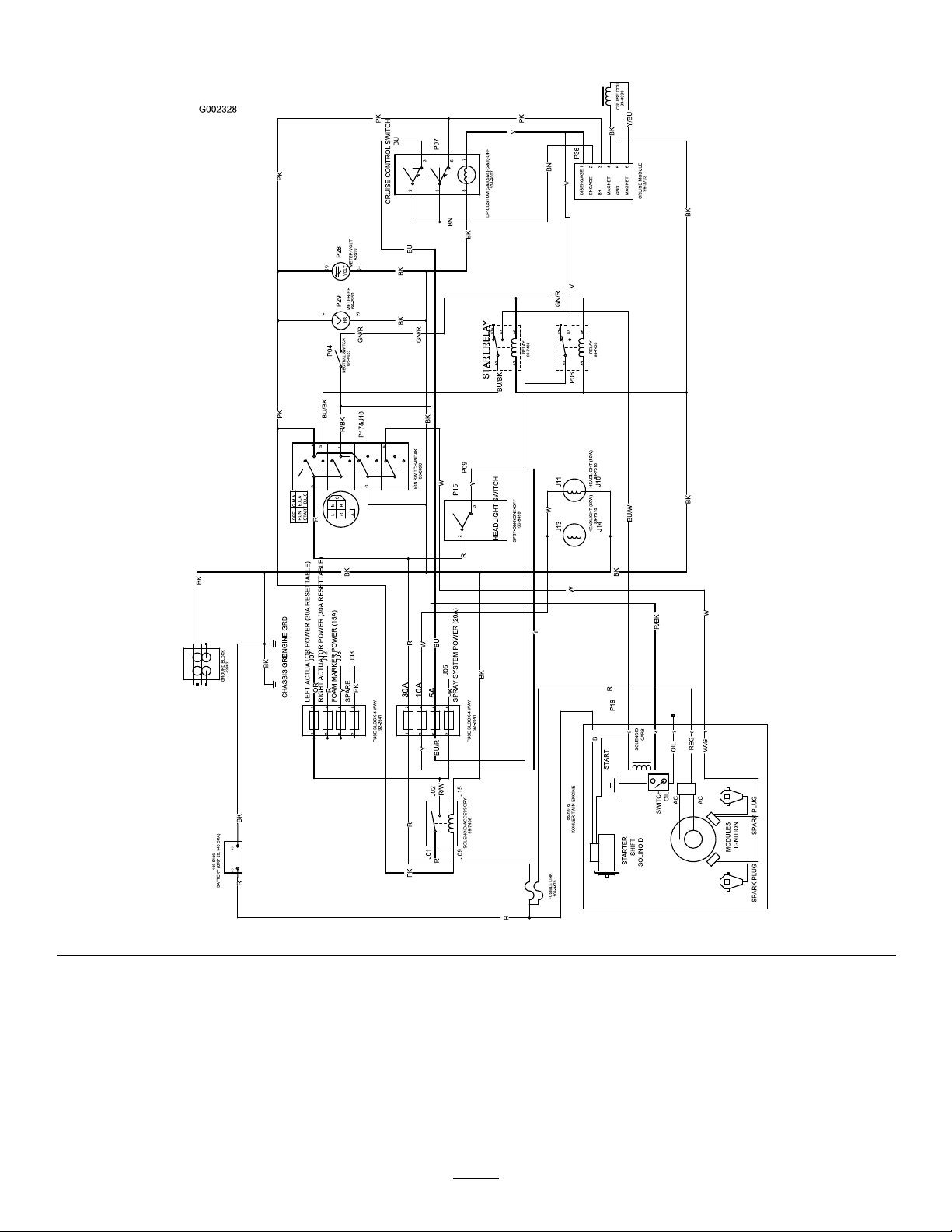
Schematics
ElectricalSchematic,Vehicle(Rev.B)
63
Page 64
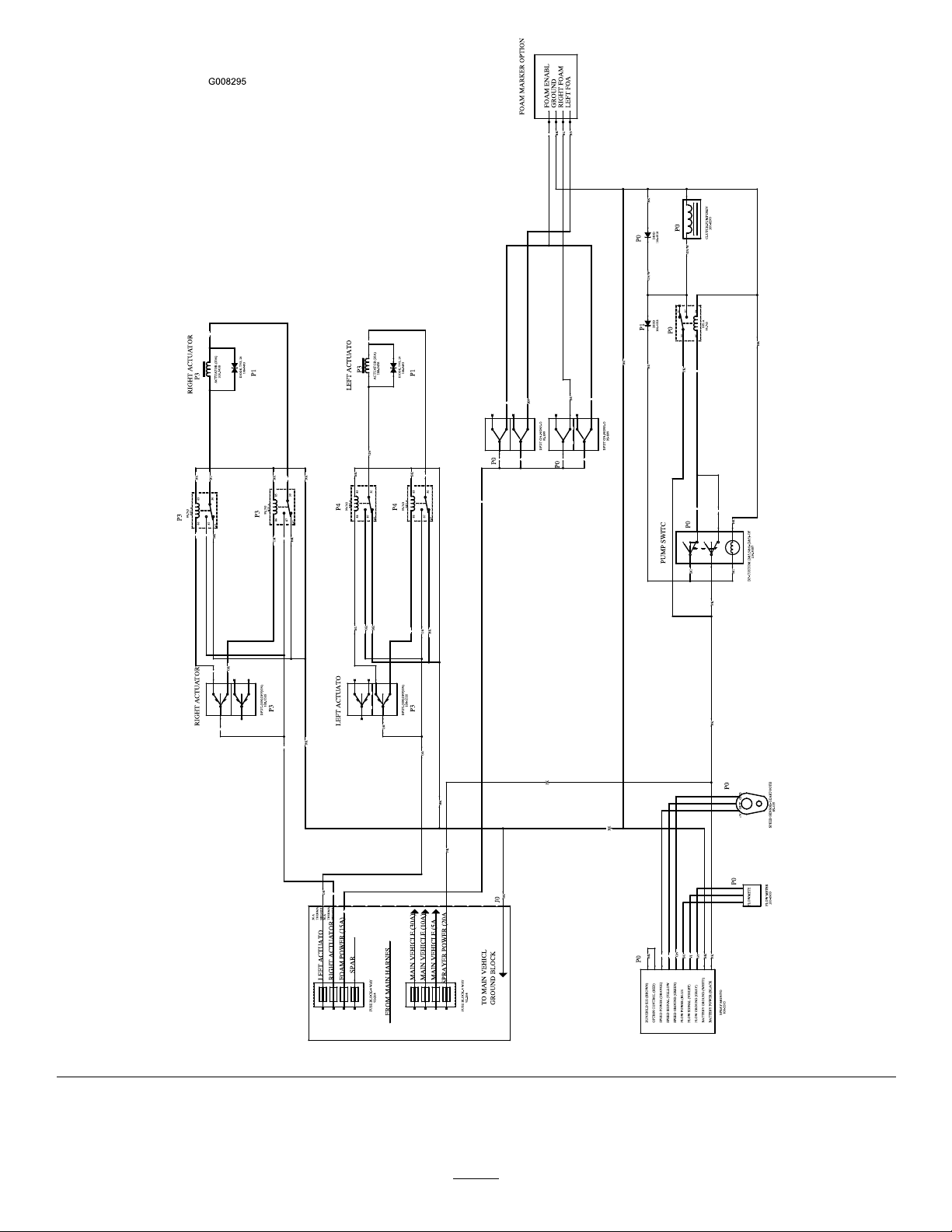
ElectricalSchematic,SpraySystem(Rev.A)
64
Page 65
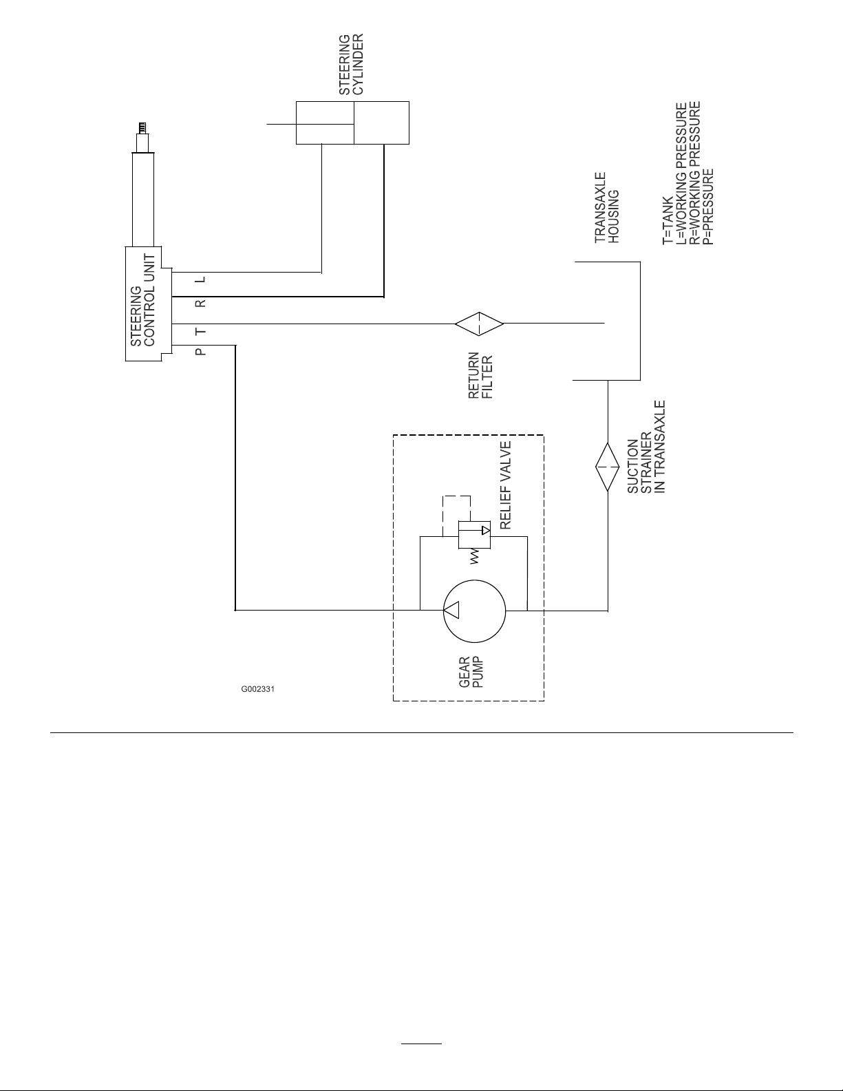
HydraulicSchematic(Rev.-)
65
Page 66

Notes:
66
Page 67

Notes:
67
Page 68

TheT oroTotalCoverageGuarantee
ALimitedWarranty
ConditionsandProductsCovered
TheToroCompanyanditsafliate,T oroWarrantyCompany ,pursuant
toanagreementbetweenthem,jointlywarrantyourT oroCommercial
product(“Product”)tobefreefromdefectsinmaterialsorworkmanship
fortwoyearsor1500operationalhours*,whicheveroccursrst.This
warrantyisapplicabletoallproductswiththeexceptionofAerators
(refertoseparatewarrantystatementsfortheseproducts).Wherea
warrantableconditionexists,wewillrepairtheProductatnocosttoyou
includingdiagnostics,labor,parts,andtransportation.Thiswarranty
beginsonthedatetheProductisdeliveredtotheoriginalretailpurchaser.
*Productequippedwithanhourmeter.
InstructionsforObtainingWarrantyService
YouareresponsiblefornotifyingtheCommercialProductsDistributoror
AuthorizedCommercialProductsDealerfromwhomyoupurchasedthe
Productassoonasyoubelieveawarrantableconditionexists.Ifyouneed
helplocatingaCommercialProductsDistributororAuthorizedDealer,or
ifyouhavequestionsregardingyourwarrantyrightsorresponsibilities,
youmaycontactusat:
ToroCommercialProductsServiceDepartment
ToroWarrantyCompany
811 1LyndaleAvenueSouth
Bloomington,MN55420-1196
952–888–8801or800–952–2740
E-mail:[email protected]
OwnerResponsibilities
AstheProductowner ,youareresponsibleforrequiredmaintenance
andadjustmentsstatedinyourOperator'sManual.Failuretoperform
requiredmaintenanceandadjustmentscanbegroundsfordisallowinga
warrantyclaim.
ItemsandConditionsNotCovered
Notallproductfailuresormalfunctionsthatoccurduringthewarranty
periodaredefectsinmaterialsorworkmanship.Thiswarrantydoesnot
coverthefollowing:
•Productfailureswhichresultfromtheuseofnon-Tororeplacement
parts,orfrominstallationanduseofadd-on,ormodiednon-T oro
brandedaccessoriesandproducts.Aseparatewarrantymaybe
providedbythemanufactureroftheseitems.
•Productfailureswhichresultfromfailuretoperformrecommended
maintenanceand/oradjustments.Failuretoproperlymaintainyour
ToroproductpertheRecommendedMaintenancelistedinthe
Operator’sManualcanresultinclaimsforwarrantybeingdenied.
•ProductfailureswhichresultfromoperatingtheProductinan
abusive,negligent,orrecklessmanner .
•Partssubjecttoconsumptionthroughuseunlessfoundtobe
defective.Examplesofpartswhichareconsumed,orusedup,
duringnormalProductoperationinclude,butarenotlimitedto,brake
padsandlinings,clutchlinings,blades,reels,rollersandbearings
(sealedorgreasable),bedknives,sparkplugs,castorwheelsand
bearings,tires,lters,belts,andcertainsprayercomponentssuchas
diaphragms,nozzles,andcheckvalves,etc.
•Failurescausedbyoutsideinuence.Conditionsconsideredtobe
outsideinuenceinclude,butarenotlimitedto,weather,storage
practices,contamination,useofunapprovedfuels,coolants,
lubricants,additives,fertilizers,water,orchemicals,etc.
•Failureorperformanceissuesduetotheuseoffuels(e.g.gasoline,
diesel,orbiodiesel)thatdonotconformtotheirrespectiveindustry
standards.
•Normalnoise,vibration,wearandtear,anddeterioration.
•Normal“wearandtear”includes,butisnotlimitedto,damageto
seatsduetowearorabrasion,wornpaintedsurfaces,scratched
decalsorwindows,etc.
Parts
Partsscheduledforreplacementasrequiredmaintenancearewarranted
fortheperiodoftimeuptothescheduledreplacementtimeforthatpart.
Partsreplacedunderthiswarrantyarecoveredforthedurationofthe
originalproductwarrantyandbecomethepropertyofT oro.T orowill
makethenaldecisionwhethertorepairanyexistingpartorassemblyor
replaceit.T oromayuseremanufacturedpartsforwarrantyrepairs.
DeepCycleandLithium-IonBatteryWarranty:
DeepcycleandLithium-Ionbatterieshaveaspeciedtotalnumberof
kilowatt-hourstheycandeliverduringtheirlifetime.Operating,recharging,
andmaintenancetechniquescanextendorreducetotalbatterylife.Asthe
batteriesinthisproductareconsumed,theamountofusefulworkbetween
chargingintervalswillslowlydecreaseuntilthebatteryiscompletelyworn
out.Replacementofwornoutbatteries,duetonormalconsumption,
istheresponsibilityoftheproductowner.Batteryreplacementmaybe
requiredduringthenormalproductwarrantyperiodatowner’sexpense.
Note:(Lithium-Ionbatteryonly):ALithium-Ionbatteryhasapartonly
proratedwarrantybeginningyear3throughyear5basedonthetime
inserviceandkilowatthoursused.RefertotheOperator'sManualfor
additionalinformation.
MaintenanceisatOwner’sExpense
Enginetune-up,lubrication,cleaningandpolishing,replacementoflters,
coolant,andcompletingrecommendedmaintenancearesomeofthe
normalservicesT oroproductsrequirethatareattheowner’sexpense.
GeneralConditions
RepairbyanAuthorizedT oroDistributororDealerisyoursoleremedy
underthiswarranty .
NeitherTheToroCompanynorT oroWarrantyCompanyisliablefor
indirect,incidentalorconsequentialdamagesinconnectionwiththe
useoftheToroProductscoveredbythiswarranty ,includingany
costorexpenseofprovidingsubstituteequipmentorserviceduring
reasonableperiodsofmalfunctionornon-usependingcompletion
ofrepairsunderthiswarranty.ExceptfortheEmissionswarranty
referencedbelow,ifapplicable,thereisnootherexpresswarranty.
Allimpliedwarrantiesofmerchantabilityandtnessforuseare
limitedtothedurationofthisexpresswarranty .
Somestatesdonotallowexclusionsofincidentalorconsequential
damages,orlimitationsonhowlonganimpliedwarrantylasts,sothe
aboveexclusionsandlimitationsmaynotapplytoyou.Thiswarranty
givesyouspeciclegalrights,andyoumayalsohaveotherrightswhich
varyfromstatetostate.
Noteregardingenginewarranty:
TheEmissionsControlSystemonyourProductmaybecoveredby
aseparatewarrantymeetingrequirementsestablishedbytheU.S.
EnvironmentalProtectionAgency(EP A)and/ortheCaliforniaAir
ResourcesBoard(CARB).Thehourlimitationssetforthabovedonot
applytotheEmissionsControlSystemWarranty.RefertotheEngine
EmissionControlWarrantyStatementsuppliedwithyourproductor
containedintheenginemanufacturer’sdocumentationfordetails
CountriesOtherthantheUnitedStatesorCanada
CustomerswhohavepurchasedT oroproductsexportedfromtheUnitedStatesorCanadashouldcontacttheirT oroDistributor(Dealer)toobtain
guaranteepoliciesforyourcountry ,province,orstate.IfforanyreasonyouaredissatisedwithyourDistributor'sserviceorhavedifcultyobtaining
guaranteeinformation,contacttheT oroimporter.
374-0253RevB
 Loading...