

Page 1
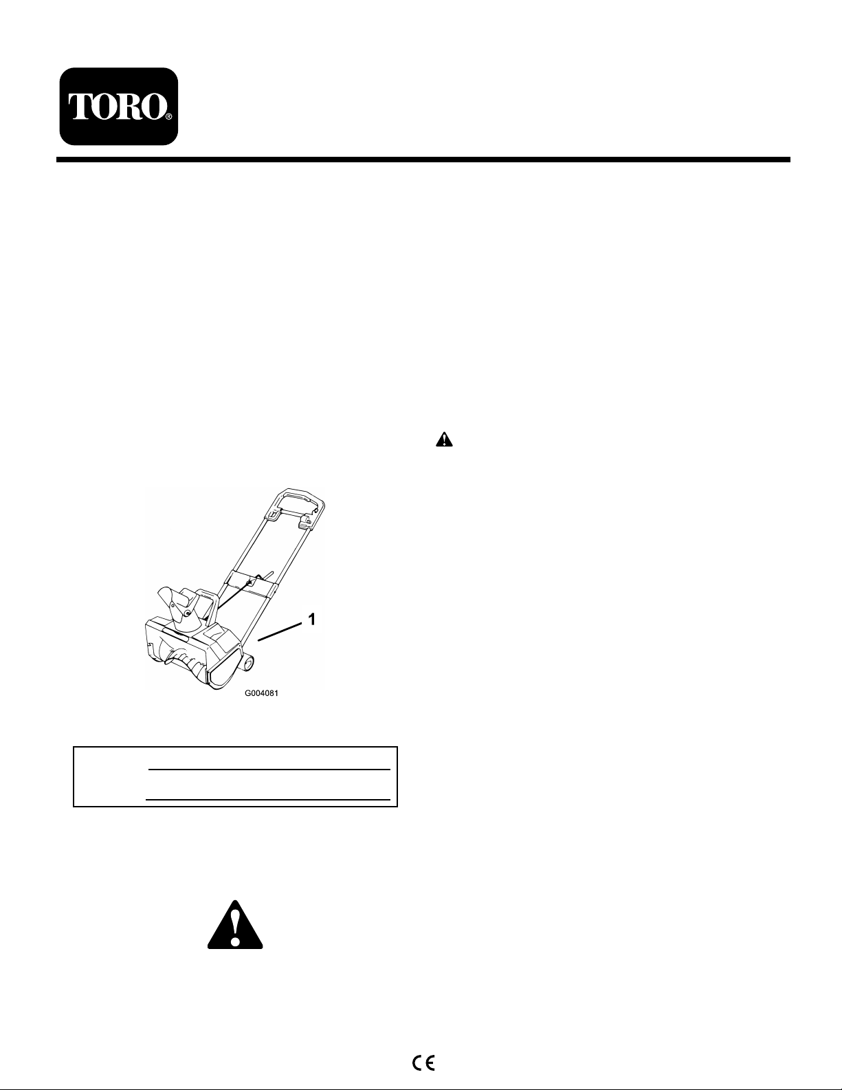
1800 Power Curve® Snowthrower
Model No. 38026 —Serial No. 270000001 and Up
Form No. 3354-207 Rev A
Operator's Manual
Introduction
R ead this infor mation carefully to lear n ho w to operate and
maintain y our product properly and to a v oid injur y and
product damag e . Y ou are responsible for operating the
product properly and safely .
Y ou ma y contact T oro directly at www .T oro .com for
product and accessor y infor mation, help finding a dealer ,
or to register y our product.
W henev er y ou need ser vice , g en uine T oro par ts , or
additional infor mation, contact an A uthorized Ser vice
Dealer or T oro Customer Ser vice and ha v e the model and
serial n umbers of y our product ready . Figure 1 identifies the
location of the model and serial n umbers on the product.
W rite the n umbers in the space pro vided.
T his man ual uses 2 other w ords to highlight infor mation.
Impor tant calls attention to special mec hanical infor mation
and Note emphasizes g eneral infor mation w or th y of special
attention.
Safety
T his sno wthr o w er meets or ex ceeds the ISO standard
8437 in ef fect at the time of pr oduction.
R ead and under stand the contents of this man ual
bef or e the engine is ev er star ted.
T his is the safety aler t symbol. It is used to aler t y ou
to potential per sonal injur y hazards. Obey all safety
messa ges that f ollo w this symbol to a v oid possible
injur y or death.
Impr oper l y using or maintaining this sno wthr o w er
could r esult in injur y or death. T o r educe this potential,
compl y with the f ollo wing safety instr uctions.
T he follo wing instr uctions ha v e been adapted from the
ANSI/OPEI standard B71.3-1995, the ISO 8437:1989
standard, and European Standard EN 786:1996 and EN
60335-2-91:2002.
Figure 1
1. Model and serial number location
Model No.
Serial No.
T his man ual identifies potential hazards and has safety
messag es identified b y the safety aler t symbol ( Figure 2 ),
whic h signals a hazard that ma y cause serious injur y or
death if y ou do not follo w the recommended precautions .
Figure 2
1. Safety alert symbol
© 2006—The Toro® Company
8111 Lyndale Avenue South
Bloomington, MN 55420
Register at www.Toro.com. Original Instructions (EN)
Training
• R ead the operator’ s man ual carefully . Be thoroughly
familiar with the controls and the proper use of the
equipment. Kno w ho w to stop the unit and diseng ag e
the controls quic kly .
• Nev er allo w c hildren to operate the sno wthro w er .
Nev er allo w adults to operate the sno wthro w er without
proper instr uction.
• K ee p the area of operation clear of all persons
(par ticularly small c hildren) and pets .
• Ex ercise caution to a v oid slipping or falling .
Preparation
• T horoughly inspect the area where y ou will use the
sno wthro w er . R emo v e all door mats , sleds , boards ,
wires , and other foreign objects .
• R elease the control bar to diseng ag e the rotor blades
before star ting the engine .
Printed in the USA.
All Rights Reserved
Page 2

• Do not operate the sno wthro w er without w earing
adequate winter g ar ments . W ear footw ear that will
impro v e y our footing on slipper y surfaces .
• Nev er attempt to mak e any adjustments while the motor
is r unning, ex ce pt where specifically recommended b y
T oro .
• Let the motor and the sno wthro w er adjust to the
outdoor temperature before star ting to clear sno w .
• Operating any po w ered mac hine can result in foreign
objects being thro wn into the eyes . Alw a ys w ear safety
glasses or eye shields while operating, adjusting, or
re pairing the sno wthro w er .
• Alw a ys ensure that the v entilation openings are k e pt
clear of debris .
• Before use , c hec k the supply and extension cord for
signs of damag e or aging .
• Nev er operate the sno wthro w er without proper guards ,
plates , or other safety protecti v e devices in place .
• Nev er operate the sno wthro w er near glass enclosures ,
automobiles , windo w w ells , and drop-offs without
properly adjusting the sno w disc harg e angle . K ee p
c hildren and pets a w a y .
• Do not o v erload the mac hine capacity b y attempting to
clear sno w at too fast a rate .
• Look behind and use care when bac king up with the
sno wthro w er .
• Nev er direct the disc harg e at b ystanders or allo w any one
in front of the unit.
• Nev er operate the sno wthro w er without g ood visibility
or light. Alw a ys be sure of y our footing, and k ee p a fir m
hold on the handle . W alk; nev er r un.
Operation
• Do not put hands or feet near or under rotating par ts .
K ee p clear of the disc harg e opening at all times .
• Disconnect the mac hine from the po w er source before
c hec king, cleaning, or w orking on the mac hine and
when it is not in use .
• If the cord becomes damag ed during use , disconnect
the cord from the po w er supply immediately . Do not
touc h the cord before disconnecting the po w er supply .
• Do not use the mac hine if the cord is damag ed or w or n.
• K ee p extension cords a w a y from the rotor blades .
• T he po w er supply used with the appliance should be a
residential cur rent device (R CD) with a tripping cur rent
of not more than 30 mA.
• Ex ercise extreme caution when crossing g ra v el dri v es ,
w alks , or roads . Sta y aler t for hidden hazards or traffic .
• Do not attempt to clear sno w from a cr ushed-roc k or
g ra v el surface . T his product is intended for use only on
pa v ed surfaces .
• After striking a foreign object, stop the motor ,
thoroughly inspect the sno wthro w er for any
damag e , and re pair the damag e before operating the
sno wthro w er .
• If the unit should star t to vibrate abnor mally , stop the
motor and c hec k immediately for the cause . Vibration
is g enerally a w ar ning of trouble .
• Stop the motor whenev er y ou lea v e the operating
position, before unclog ging the disc harg e c hute , and
when making any re pairs , adjustments , or inspections .
• W hen cleaning, re pairing, or inspecting, mak e cer tain
that the rotor blades and all mo ving par ts ha v e stopped.
• Do not clear sno w across the face of slopes . Ex ercise
extreme caution when c hanging direction on slopes . Do
not attempt to clear stee p slopes .
Maintenance and Storage
• Chec k all fasteners at frequent inter v als for proper
tightness to be sure that the equipment is in safe
w orking condition.
• Alw a ys refer to this operator’ s man ual for impor tant
details if the sno wthro w er is to be stored for an
extended period.
• Maintain or re place safety and instr uction labels when
necessar y .
Toro Snowthrower Safety
T he follo wing list contains safety infor mation specific to
T oro products or other safety infor mation that y ou m ust
kno w .
• R otating rotor blades can injure fing ers or hands .
Sta y behind the handles and a w a y from the disc harg e
opening while operating the sno wthro w er . K ee p y our
face , hands , feet, and any other par t of y our body or
clothing a w a y from mo ving or rotating par ts .
• Before adjusting, cleaning, re pairing, and inspecting
the sno wthro w er , and before unclog ging the disc harg e
c hute , stop the motor and w ait for all mo ving par ts to
stop .
• Use a stic k, not y our hands , to remo v e obstr uctions
from the disc harg e c hute .
• Before lea ving the operating position, stop the motor
and w ait for all mo ving par ts to stop .
• Do not w ear loose-fitting clothing that could g et caught
in mo ving par ts .
• If a shield, safety device , or decal is damag ed, illegible ,
or lost, re pair or re place it before beginning operation.
Also , tighten any loose fasteners .
• Do not use the sno wthro w er on a roof .
2
Page 3
• P erfor m only those maintenance instr uctions described
Sound Power
in this man ual. Before perfor ming any maintenance ,
ser vice , or adjustment, stop the motor and disconnect
the po w er cord from the po w er source . If major re pairs
T his unit has a guaranteed sound po w er lev el of 104 dB A,
based on measurements of identical mac hines per EN 3744.
are ev er needed, contact y our A uthorized Ser vice
Dealer .
Vibration
• Purc hase only g en uine T oro re placement par ts and
accessories .
T his unit does not ex ceed a hand/ar m vibration lev el of
2.3 m/s
2
, based on measurements of identical mac hines
per EN 1033.
Sound Pressure
T his unit has a maxim um sound pressure lev el at the
operator’ s ear of 89 dB A, based on measurements of
identical mac hines per EN 11201.
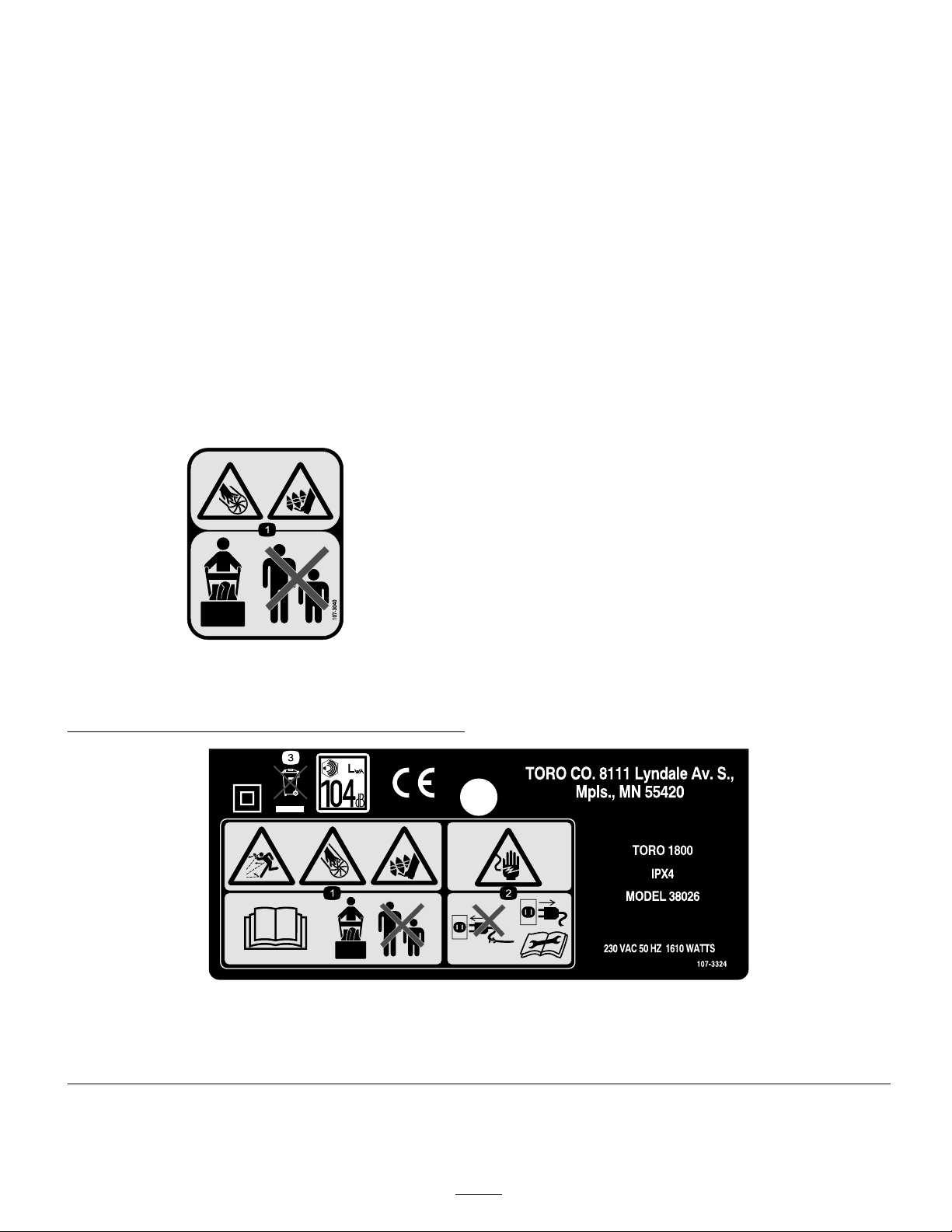
Safety and Instructional Decals
Important: Safety and instr uction decals ar e located near ar eas of potential danger . R eplace dama ged decals.
107-3040
1. Cutting dismemberment, impeller and cutting dismemberment,
auger hazards—keep bystanders a safe distance from the
snowthrower.
107-3324
1. Thrown object hazard; cutting/dismemberment hazard, impeller and auger—read the Operator’s Manual, keep bystanders a safe distance from
the machine.
2. Electric shock hazard—disconnect the machine from the power outlet and read the instructions before servicing or performing maintenance.
3. Contains recyclable materials, do not discard.
3
Page 4
Setup
Loose Parts
Use the chart below to verify that all parts have been shipped.
Step
Mounting plate
Chute crank
1.
2.
Note: Deter mine the left and right sides of the mac hine from the nor mal operating position.
Machine screw
Locknut
Chute deector
Rubber washer
Carriage bolt
Metal washer
Locknut
Description
Qty.
1
1
2
2
1
2
2
2
2
1. Installing the Upper Handle
and Chute Crank
1. Stand the sno wthro w er on its wheels and position the
upper handle .
2. Inspect the open inter nal wiring; if it is damag ed, do not
assemble . Contact an A uthorized Ser vice Dealer .
Use
Install the upper handle and chute
crank.
Install the discharge chute.
T he inter nal wiring could be dama ged during
assembl y , causing serious per sonal injur y when
operating the sno wthr o w er .
• Car efull y assemble the sno wthr o w er so that
y ou will not dama ge the electrical wiring .
• If the wiring is dama ged, do not assemble the
sno wthr o w er . Contact an Authoriz ed Ser vice
Dealer .
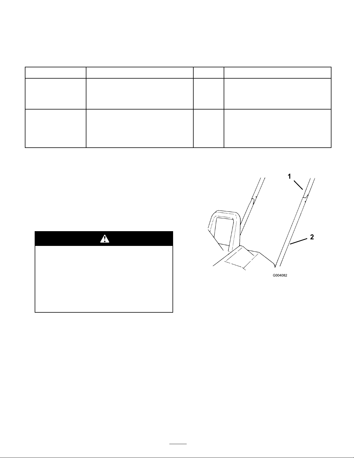
3. Carefully inser t the right side of the upper tubing o v er
the end of the lo w er right side tubing ( Figure 3 ).
Figure 3
1. Upper tubing 2. Lower tubing
4. Carefully inser t the left side of the upper tubing into the
end of the lo w er left side tubing ( ).
5. Squeeze the upper tubes tog ether , and wig gle the upper
tubes do wn until the mounting holes in the upper and
lo w er tubing line up ( Figure 3 ).
6. Place the mounting plate o v er the tubes ( Figure 4 ).
4
Page 5

Figure 4
1. Mounting plate 3. Chute crank
2. Shroud
4. Gear
7. Align the mounting plate holes with the upper and
lo w er tubing holes .
8. Inser t the end of the c hute crank through the hole in
the shroud.
9. T ur n the c hute crank rod slo wly until the flattened end
drops into the slot in the g ear , then fir mly push the
c hute crank into the g ear until it snaps into place ( Figure
4 and Figure 5 ).
Figure 5
1. Chute crank 2. Chute crank gear
Figure 6
1. Chute deector
2. Discharge chute
3. Rubber washer (2) 6. Locknut (2)
4. Carriage bolt (2)
5. Metal washer (2)
2. Inser t a r ubber w asher betw een the c hute deflector and
the disc harg e c hute on eac h side while maintaining the
hole alignment ( Figure 6 ).
3. Secure the deflector to the disc harg e c hute with 2
car riag e bolts , 2 metal w ashers , and 2 loc kn uts .
Note: Ensure that the square shoulders on the car riag e
bolts align with the inside square on the disc harg e c hute .
P osition the metal w ashers to the outside of the c hute
deflector as sho wn in Figure 6 . Do not o v er tighten the
bolts .
Product Overview
10. Secure the upper and lo w er tubing and the mounting
plate tog ether with 2 mac hine screws and 2 loc kn uts .
Note: P osition the screw heads on the outside of the
mounting plate . Be careful not to damag e the inter nal
electrical wiring when y ou inser t the screws . If the
wiring bloc ks the hole , use a blunt 1/8 inc h punc h
to carefully route the electrical wiring a w a y from the
aligned holes .
2. Installing the Discharge
Chute
1. P osition the c hute deflector onto the disc harg e c hute
and align the mounting holes ( Figure 6 ).
Figure 7
1. Control bar 5. Discharge chute
2. Chute crank 6. Chute deector
3. Belt cover 7. Secondary handle
4. Rotor
5
Page 6

Operation
Before Starting
F or safe and efficient use of y our appliance , use only an
extension cord recommended for outdoor use . Use only a
2.5 mm extension cord up to 25 m long .
Contact with w ater while operating the sno wthr o w er
can cause electric shock, r esulting in per sonal injur y
or death.
Don’ t handle the plug or the appliance with w et
hands or while standing in w ater .
Starting and Stopping
1. T o star t the rotor , squeeze the control bar ( Figure 9 ).
Figure 9
1. Control bar
2. T o stop the rotor , release the control bar .
Note: T o prev ent the extension cord from disconnecting
during operation, tie it to the loop in the upper handle
before y ou connect it to the sno wthro w er ( Figure 8 ).
Figure 8
1. Extension cord
T he electrical cord can get dama ged, causing a
shock or fir e.
T hor oughl y inspect the electrical cord bef or e using
the sno wthr o w er . If the cord is dama ged, do not
operate the sno wthr o w er . R epair or r eplace the
dama ged cord immediatel y . Contact an Authoriz ed
Ser vice Dealer f or assistance.
2. Loop
Operating Tips
If sno wthr o w er hits an object while in operation, the
object could be thr o wn in operator’ s or bystander’ s
dir ection. T hr o wn objects could cause serious
per sonal injur y .
K eep the ar ea to be clear ed fr ee of all objects which
may be pick ed up and thr o wn by the r otor blades.
• Chec k the condition of the sno wthro w er before
operating it to ensure that the rotor tur ns freely .
• Alw a ys k ee p c hildren and pets a w a y from the area of
operation.
• K ee p the area to be cleared free of stones , to ys , or other
objects whic h the rotor blades can thro w . Suc h items
could be co v ered b y sno wfall and g o unnoticed. If the
sno wthro w er strik es an object during operation, stop the
sno wthro w er , unplug the extension cord, remo v e the
obstr uction, and c hec k the sno wthro w er for damag e .
• T o adjust the disc harg e c hute , rotate the c hute crank
cloc kwise to mo v e the disc harg e c hute to the left;
countercloc kwise to mo v e it to the right.
Note: T he c hute crank mak es a noise as y ou tur n the
crank. T his is nor mal.
• T o adjust the height of the sno w stream, raise or lo w er
the c hute deflector handle ( Figure 10 ).
6
Page 7

Figure 10
1. Chute deector handle
A gap betw een the discharge chute and the chute
deflector may allo w the sno wthr o w er to thr o w
sno w and objects in the dir ection of the operator .
T hr o wn objects could cause serious per sonal
injur y .
Figure 11
1. Primary handle 2. Secondary handle
• W hen clearing ste ps , hold the sno wthro w er b y the
primar y and secondar y handles and use a swinging or
sw ee ping motion.
– Do not f orce the chute deflector too f ar
f orw ard so that a gap appear s betw een the
discharge chute and chute deflector .
– Do not o v er tighten the lockn uts that hold the
chute deflector in place.
• Begin remo ving sno w near the electrical outlet and
w ork outw ard. Blo w bac k and for th, not a w a y from
and to w ard the outlet.
• W hen tur ning at the end of a sw ath, ste p o v er the cord
and tur n the sno wthro w er .
• Alw a ys o v erlap eac h sw ath and disc harg e the sno w
do wnwind when possible .
• T o sha v e do wn larg e banks of sno w , lift the sno wthro w er
b y the primar y and secondar y handles ( Figure 11 )
and place the sno wthro w er on the bank. Let the
w eight of the sno wthro w er sha v e do wn the bank in a
bac k-and-for th motion.
W hen using the secondar y handle, nev er dir ect
the sno w discharge chute at the operator or
bystander s. T he sno wthr o w er can thr o w objects
and cause serious per sonal injur y .
W hen using the secondar y handle, al w ays tur n
the discharge chute in the opposite dir ection
fr om wher e y ou or bystander s ar e standing .
• K ee p the extension cord clear of obstr uctions , shar p
objects , and all mo ving par ts . Do not pull shar ply on
cord or abuse it in any manner . F requently inspect the
extension cord for damag e that ma y result in an electric
shoc k. If the extension cord becomes damag ed, re place
it.
• In cold and sno wy w eather conditions , some controls
and mo ving par ts ma y freeze . T herefore , when any
control becomes difficult to operate , stop the motor ,
disconnect the extension cord, and c hec k for frozen
par ts . Do not use ex cessi v e force when tr ying to operate
frozen controls . F ree all the controls and mo ving par ts
before operating .
• W hen operating the sno wthro w er , k ee p the wheels
1 inc h (2.5 cm) off the pa v ement b y tipping the
sno wthro w er forw ard. T his helps prev ent the sno w
from building up on the wheels .
• After clearing the sno w , let the motor r un for a few
min utes so that mo ving par ts don ’ t freeze . T hen shut
off the motor , w ait for all mo ving par ts to stop , and
wipe the ice and sno w off the sno wthro w er . R otate the
c hute crank sev eral times to remo v e the sno w .
7
Page 8

Maintenance
Important: All electrical r epair s should be
perf or med onl y by an Authoriz ed Ser vice Dealer .
Note: Deter mine the left and right sides of the mac hine
from the nor mal operating position.
If the extension cord is plug ged into the
sno wthr o w er , someone could accidentall y operate
sno wthr o w er while y ou ar e perf or ming maintenance
on it, causing serious per sonal injur y .
Disconnect the extension cord bef or e y ou perf or m
an y maintenance.
Lubricating the Snowthrower
Y ou do not need to lubricate the sno wthro w er; all the
bearings w ere lubricated at the factor y for the life of the
sno wthro w er .
Replacing the Scraper
T he scraper is located at the bottom of the rotor housing
as sho wn in Figure 12 .
Figure 13
1. Right side cover 3. Skid
2. Screw
2. Use a 5/16 inc h Allen wrenc h to tur n the rotor shaft
cloc kwise (left-hand thread) while holding the rotor
( Figure 14 ).
Figure 14
1. Rotor shaft
2. Rotor
Note: Y ou ma y need to tap the Allen wrenc h with a
hammer to loosen the rotor shaft. W edg e a stic k or a
hammer handle in the rotor to prev ent it from rotating .
Figure 12
1. Scraper
2. Screw (2)
1. R emo v e the 2 screws that secure the scraper to the
sno wthro w er ( Figure 12 ).
2. Install the new scraper and fasten it securely with 2
screws .
Replacing the Rotor
1. R emo v e the 3 screws that secure the right side co v er
and the skid to the sno wthro w er frame ( Figure 13 ).
Note: If y ou cannot remo v e the rotor shaft b y holding
the rotor , remo v e the left side co v er and the skid ( Figure
15 ).
Figure 15
1. Left side cover 2. Skid
3. Hold the hex n ut with a 7/8 inc h wrenc h while
unscrewing the rotor shaft ( Figure 16 ).
Figure 16
1. Hex nut
8
Page 9

4. Hold the rotor and pull out the rotor shaft.
5. R emo v e the rotor .
6. Align the left side of the new rotor with the coupler .
Note: T he 3 bosses on the rotor end m ust align with
the slots on the coupler ( Figure 17 ).
Figure 17
1. Coupler 3. Slot
2. Boss
4. Drive hex
Note: W hen mounting the coupler to the dri v e hex,
align the coupler tabs to the inside .
Figure 18
1. Idler spring 2. Idler arm
4. R otate the rotor with y our left hand while sliding the
belt off the larg e pulley with y our right hand ( Figure 19 ).
7. Slide the right side of the rotor into the mounting
position.
8. Inser t the rotor shaft through the rotor and ensure that
the shaft fits into the bearing on the right side .
9. T or que it to at least 10 ft-lb (14 N ⋅ m).
10. Install the co v er and the skid.
Replacing the Large Belt
1. R emo v e the 3 screws that secure the left side plate to
the sno wthro w er frame ( Figure 15 ).
2. R emo v e the side plate and the skid.
T he idler spring could fly in y our f ace while y ou
r emo v e it, causing per sonal injur y .
W ear safety go g g les when w or king with the idler
spring .
3. R emo v e the idler spring from the idler ar m ( Figure 18 ).
Figure 19
1. Large pulley 2. Belt
5. Slip the new belt o v er the small pulley ( Figure 20 ).
Figure 20
1. Idler arm 3. Small pulley
2. Idler pulley
6. Lift up the idler ar m and slip the belt under the idler
pulley ( Figure 20 ).
7. R otate the rotor with y our left hand while sliding the
belt onto the larg e pulley with y our right hand ( Figure
21 ).
9
Page 10

Note: T he bolt, the bolt head, and the w ashers m ust
be flush ag ainst the small pulley .
11. Slip the larg e belt o v er the small pulley ( Figure 22 ).
R efer to R e placing the Larg e Belt.
Storage
Figure 21
8. Assemble the idler spring ( Figure 18 ), ensuring that the
idler pulley rides on the belt.
9. Install the left side co v er and the skid with the 3 screws .
Replacing the Small Belt
1. R emo v e the screws that secure the left side plate and
the skid to the sno wthro w er frame ( Figure 15 ).
2. R emo v e the side plate and the skid.
3. R emo v e the larg e belt b y slo wly sliding it off the small
pulley (Fig . Figure 19 ).
Note: R efer to ste ps 2 and 3 of R e placing the Larg e
Belt.
4. R emo v e the small pulley bolt (left hand thread) b y
tur ning the bolt cloc kwise .
5. R emo v e the 2 w ashers and the small pulley ( Figure 22 ).
1. R un the sno wthro w er for a few min utes to melt a w a y
any sno w on the sno wthro w er .
2. Disconnect the extension cord from the sno wthro w er .
3. Examine the extension cord thoroughly for signs of
w ear or damag e . R e place it if it is w or n or damag ed.
4. Examine the sno wthro w er thoroughly for w or n, loose ,
or damag ed par ts . T o re pair or re place par ts , contact an
local A uthorized Ser vice Dealer for assistance .
5. Store the extension cord with the sno wthro w er .
6. Store the sno wthro w er in a clean, dr y place .
Figure 22
1. Bolt (left-hand thread)
2. Washers 5. Motor shaft pulley
3. Small pulley
6. R emo v e and discard the small belt ( Figure 22 ).
7. Slide 2 w ashers onto the bolt and inser t the bolt through
the small pulley .
Note: T he bolt m ust ride on the bearings in the small
pulley .
8. Place the new belt on the small pulley .
9. Slide the belt o v er the motor shaft pulley ( Figure 22 ).
10. T or que the bolt to 25 to 30 in-lb (2.8 to 3.4 N∙m). Do
not o v er tighten the bolt.
4. Small belt
10
Page 11

International Distributor List—Consumer Products
Distributor:
Atlantis Su ve Sulama Sisstemleri Lt Turkey
Balama Prima Engineering Equip
B-Ray Corporation
Casco Sales Company
Ceres S.A
CSSC Turf Equipment (pvt) Ltd
Cyril Johnston & Co Nothern Ireland
Equiver Mexico
Femco S.A.
G.Y.K. Company ltd.
Geomechaniki of Athens
Guandong Golden Star China
Hako Gorund and Garden Sweden
Hydroturf Int. Co Dubai United Arab Emirates
Hydroturf Egypt LLC
Ibea S.p.A. Italy
Irriamc
Jean Heybroek b.v. Netherlands
Lely (U.K. ) Limited
Maquiver S.A.
Maruyama Mfg. Co. Inc.
Metra Kft
Mounteld a.s. Czech Republic
Munditol S.A.
Oslinger Turf Equipment SA Ecuador
Oy Hako Ground and Garden Ab Finland
Parkland Products Ltd New Zealand
Prochaska & Cie
RT Cohen 2004 Ltd Israel
Riversa Spain
Roth Motorgerate GmBh & Co
Sc Svend Carlsen A/S Denmark
Solvert S.A.S
Spypros Stavrinides Limited
Surge Systems India Limited India
T-Markt Logistics Ltd
Toro Australia Australia
Toro Europe BVBA
Country:
Hong Kong 852 2155 2163
Korea 82 32 551 2076
Puerto Rico
Costa Rica
Sri Lanka
Guatemala
Japan
Greece 30 10 935 0054
Egypt
Portugal
United Kingdom
Columbia
Japan
Hungary
Argentina
Austria
Germany 49 7144 2050
France
Cyprus 357 22 434131
Hungary
Belgium
Phone Number:
90 216 344 86 74
787 788 8383
506 239 1138
94 11 2746100
44 2890 813 121
52 55 539 95444
502 442 3277
81 726 325 861
86 20 876 51338
46 35 10 0000
97 14 347 9479
202 519 4308
39 0331 853611
351 21 238 8260
31 30 639 4611
44 1480 226 800
57 1 236 4079
81 3 3252 2285
36 1 326 3880
420 255 704 220
54 11 4 821 9999
593 4 239 6970
358 987 00733
64 3 34 93760
43 1 278 5100
972 986 17979
34 9 52 83 7500
45 66 109 200
33 1 30 81 77 00
91 1 292299901
36 26 525 500
61 3 9580 7355
32 14 562 960
374-0102 Rev A
Page 12

The Toro Warranty
Conditions and Products Covered
The Toro® Company and its afliate, Toro Warranty Company, pursuant to
an agreement between them, jointly promises to the original purchaser* to
repair any Toro Product used for normal residential purposes* if defective in
materials or workmanship. The following time periods apply from the date
of original purchase:
Products
Walk Power Mowers
Rear Engine Riders 2-year limited warranty
Lawn & Garden Tractors
Electric Hand Held Products
Snowthrowers
Consumer Zero Turn
* “Original purchaser” means use the person who originally purchased Toro
products.
* “Normal residential purposes” means use of the product on the same lot as
your home. Use at more than one location is considered commercial use, and
the commercial use warranty would apply.
Warranty Period
2-year limited warranty
2-year limited warranty
2-year limited warranty
2-year limited warranty
2-year limited warranty
Limited Warranty for Commercial Use
Toro Consumer Products and attachments used for commercial, institutional,
or rental use are warranted against defects in materials or workmanship for the
following time periods from the date of original purchase:
Products
Walk Power Mowers
Rear Engine Riders 90 day warranty
Lawn & Garden Tractors
Electric Hand Held Products
Snowthrowers
Consumer Zero Turn
Warranty Period
90 day warranty
90 day warranty
90 day warranty
90 day warranty
45 day warranty
Instructions for Obtaining Warranty Service
If you think that your Toro Product contains a defect in materials or
workmanship, follow this procedure:
1. Contact your seller to arrange service of the product. If for any reason
it is impossible for you to contact your seller, you may contact any Toro
Authorized Distributor to arrange service.
2. Bring the product and your proof of purchase (sales receipt) to your seller
or the Service Dealer.
If for any reason you are dissatised with the Service Dealer’s analysis or with the
assistance provided, contact the Toro importer or contact us at:
Customer Care Department, Consumer Division
Toro Warranty Company
8111 Lyndale Avenue South
Bloomington, MN 55420-1196
Manager: Technical Product Support: 001-952-887-8248
See attached Distributor List
Owner Responsibilities
You must maintain your Toro Product by following the maintenance procedures
described in the operator’s manual. Such routine maintenance, whether
performed by a dealer or by you, is at your expense.
Items and Conditions Not Covered
This express warranty does not cover:
• Cost of regular maintenance service or parts, such as lters, fuel, lubricants,
tune-up parts, blade sharpening, brake and clutch adjustments.
• Any product or part which has been altered or misused or required
replacement or repair due to normal wear, accidents, or lack of proper
maintenance.
• Repairs necessary due to improper fuel, contaminants in the fuel system, or
failure to properly prepare the fuel system prior to any period of non-use
over three months.
• Engine and transmission. These are covered by the appropriate
manufacturer’s guarantees with separate terms and conditions.
All repairs covered by this warranty must be performed by an Authorized Toro
Service Dealer using Toro approved replacement parts.
General Conditions
The purchaser is covered by the national laws of each country. The rights to
which the purchaser is entitled with the support of these laws are not restricted
by this warranty.
374-0101 Rev A
 Loading...