

Page 1
PowerMax
PowerMax
ModelNo.37779—SerialNo.400010798andUp
ModelNo.37780—SerialNo.400010798andUp
®
724OESnowthrower
®
826OESnowthrower
Introduction
WARNING
CALIFORNIA
Proposition65Warning
Thisproductcontainsachemicalorchemicals
knowntotheStateofCaliforniatocausecancer,
birthdefects,orreproductiveharm.
Theengineexhaustfromthisproduct
containschemicalsknowntotheStateof
Californiatocausecancer,birthdefects,
orotherreproductiveharm.
FormNo.3406-741RevA
Operator'sManual
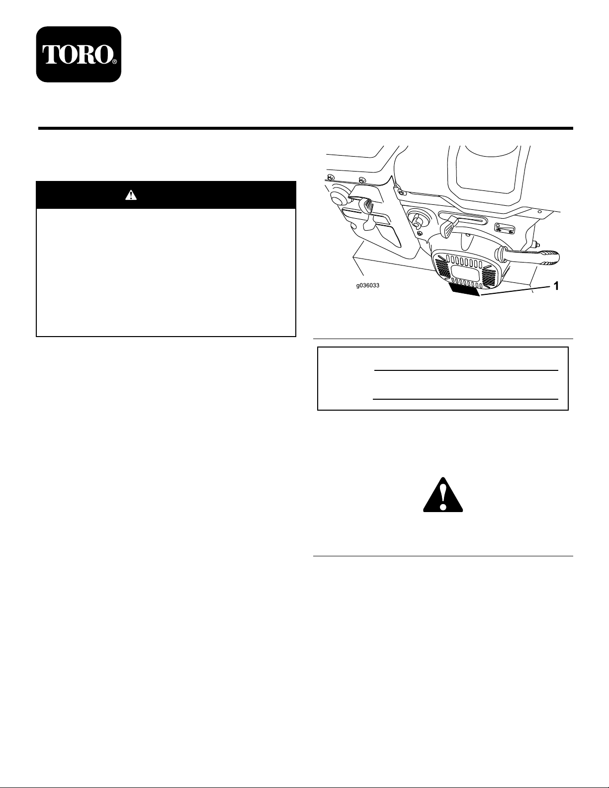
Figure1
1.Modelandserialnumberlocation
Thismachineisintendedtobeusedbyresidential
homeownersorprofessional,hiredoperators.Itis
designedforremovingsnowfrompavedsurfaces,such
asdrivewaysandsidewalks,andothersurfacesfor
trafconresidentialorcommercialproperties.Itisnot
designedforremovingmaterialsotherthansnow,noris
amodelwithapivotingscraperdesignedforclearingoff
gravelsurfaces.
Readthisinformationcarefullytolearnhowtooperateand
maintainyourmachineproperlyandtoavoidinjuryand
machinedamage.Youareresponsibleforoperatingthe
machineproperlyandsafely.
YoumaycontactTorodirectlyatwww.Toro.comformachine
andaccessoryinformation,helpndingadealer,ortoregister
yourmachine.
Wheneveryouneedservice,genuineToroparts,oradditional
information,contactanAuthorizedServiceDealerorToro
CustomerServiceandhavethemodelandserialnumbersof
yourmachineready.Figure1identiesthelocationofthe
modelandserialnumbersonthemachine.Writethenumbers
inthespaceprovided.
ModelNo.
SerialNo.
Thismanualidentiespotentialhazardsandhassafety
messagesidentiedbythesafety-alertsymbol(Figure2),
whichsignalsahazardthatmaycauseseriousinjuryordeath
ifyoudonotfollowtherecommendedprecautions.
Figure2
1.Safety-alertsymbol
Thismanualuses2wordstohighlightinformation.
Importantcallsattentiontospecialmechanicalinformation
andNoteemphasizesgeneralinformationworthyofspecial
attention.
Important:Ifyouareusingthismachineabove1500m
(5,000ft)foracontinuousperiod,ensurethattheHigh
AltitudeKithasbeeninstalledsothattheenginemeets
CARB/EPAemissionregulations.TheHighAltitude
Kitincreasesengineperformancewhilepreventing
spark-plugfouling,hardstarting,andincreased
emissions.Onceyouhaveinstalledthekit,attach
thehigh-altitudelabelnexttotheserialdecalonthe
machine.ContactanyAuthorizedT oroServiceDealer
©2016—TheT oro®Company
8111LyndaleAvenueSouth
Bloomington,MN55420
Registeratwww.T oro.com.
OriginalInstructions(EN)
PrintedintheUSA
AllRightsReserved
*3406-741*A
Page 2
toobtaintheproperHighAltitudeKitandhigh-altitude
labelforyourmachine.T olocateadealerconvenientto
you,accessourwebsiteatwww.Toro.comorcontactour
ToroCustomerCareDepartmentatthenumber(s)listed
inyourEmissionControlWarrantyStatement.
Removethekitfromtheengineandrestoretheengine
toitsoriginalfactorycongurationwhenrunningthe
engineunder1500m(5,000ft).Donotoperateanengine
thathasbeenconvertedforhigh-altitudeuseatlower
altitudes;otherwise,youcouldoverheatanddamage
theengine.
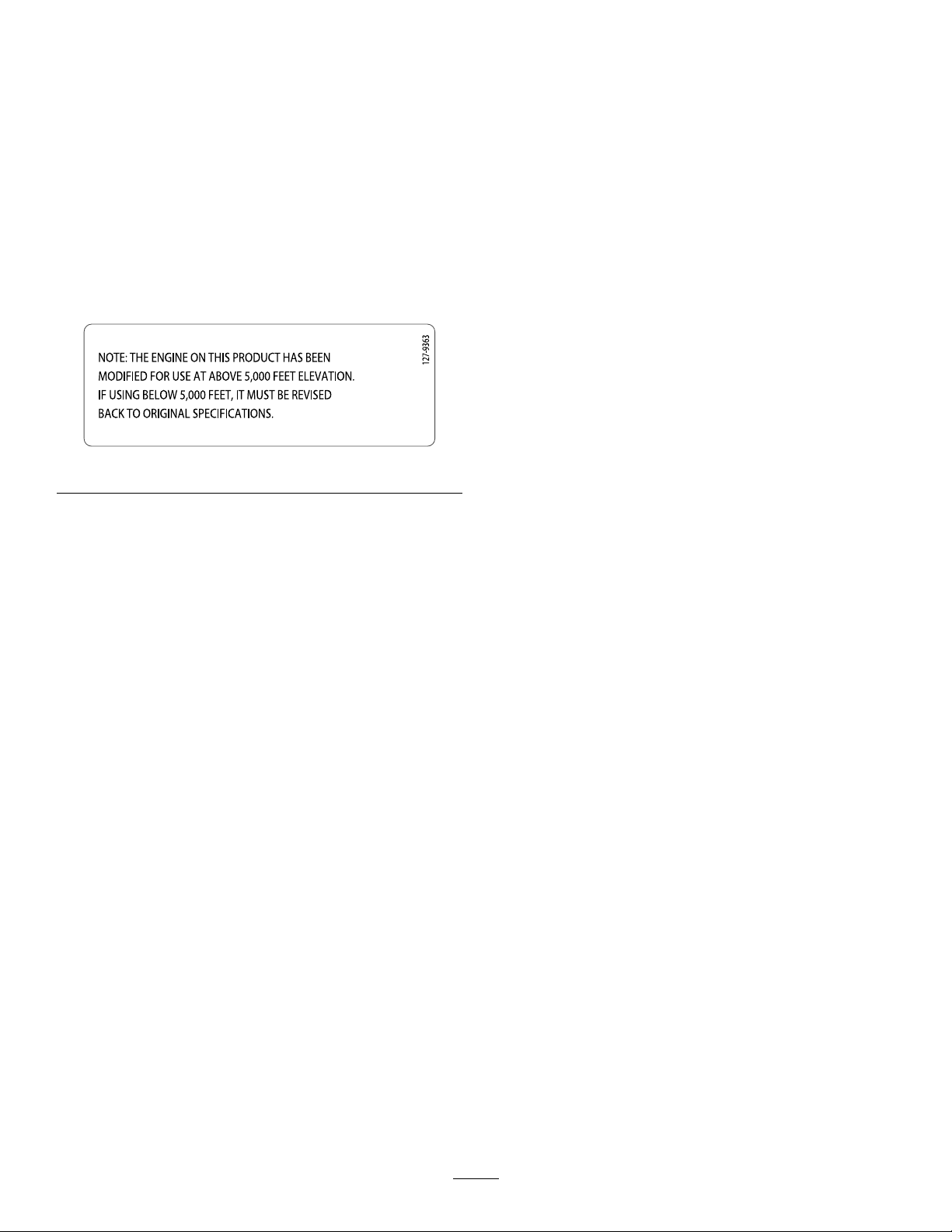
Ifyouareunsurewhetherornotyourmachinehasbeen
convertedforhigh-altitudeuse,lookforthefollowing
label(Figure3).
Figure3
ThissparkignitionsystemcomplieswithCanadianICES-002.
UncloggingtheDischargeChute..............................16
OperatingTips......................................................16
AfterOperation........................................................16
Safety....................................................................16
PreventingFreeze-upafterUse.................................17
Maintenance.................................................................17
RecommendedMaintenanceSchedule(s)......................17
MaintenanceSafety.................................................17
PreparingforMaintenance.......................................17
CheckingtheEngine-OilLevel.................................18
CheckingandAdjustingtheSkidsand
Scraper..............................................................18
CheckingandAdjustingtheTractionCable................19
CheckingandAdjustingtheAuger/Impeller
Cable................................................................19
CheckingtheAuger-Gearbox-OilLevel.....................20
ChangingtheEngineOil.........................................20
LubricatingtheHexShaft........................................21
ReplacingtheSparkPlug.........................................21
AdjustingtheDischarge-ChuteLatch........................22
ReplacingtheDriveBelts.........................................22
Storage........................................................................23
PreparingtheMachineforStorage............................23
RemovingtheMachinefromStorage.........................23
Troubleshooting...........................................................24
Contents
Introduction..................................................................1
Safety...........................................................................2
SafetyandInstructionalDecals.................................3
Setup............................................................................5
1InstallingtheUpperHandle....................................5
2InstallingtheTraction-ControlLinkage....................6
3InstallingtheChute...............................................7
4InstallingtheChute-ControlRod............................7
5CheckingtheEngine-OilLevel...............................8
6CheckingtheTirePressure.....................................8
7CheckingtheSkidsandScraper...............................8
8CheckingtheOperationoftheTraction
Drive.................................................................8
ProductOverview.........................................................10
Operation....................................................................10
BeforeOperation......................................................10
Safety....................................................................10
FillingtheFuelTank...............................................10
DuringOperation.....................................................11
Safety....................................................................11
FreewheelingorUsingtheSelf-Propel
Drive................................................................11
StartingtheEngine.................................................12
ShuttingOfftheEngine..........................................14
OperatingtheTractionDrive...................................14
OperatingtheSpeedSelector...................................14
OperatingtheAuger/ImpellerDrive.........................15
OperatingtheQuickStick™....................................15
Safety
ThismachinemeetsorcomplieswithANSIB71.3
specicationsineffectatthetimeofproduction.
•ReadandunderstandthecontentsofthisOperator’s
Manualbeforeyoustarttheengine.Ensurethateveryone
usingthisproductknowshowtousetheproductand
understandsthewarnings.
•Donotputyourhandsorfeetnearmovingcomponents
onthemachine.
•Donotoperatemachinewithoutallguardsandother
safetyprotectivedevicesinplaceandworkingonthe
machine.
•Keepclearofanydischargeopening.Keepbystandersa
safedistanceawayfromthemachine.
•Keepchildrenoutoftheoperatingarea.Neverallow
childrentooperatethemachine.
•Shutofftheenginebeforeunclogging,servicing,or
fuelingthemachine.
Youcanndadditionalitemsofsafetyinformationintheir
respectivesectionsthroughoutthismanual.
2
Page 3
SafetyandInstructionalDecals
x 3
1
2
3
4
5
120-9805
Safetyandinstructiondecalsarelocatednearareasofpotentialdanger.Replacedamagedor
missingdecals.
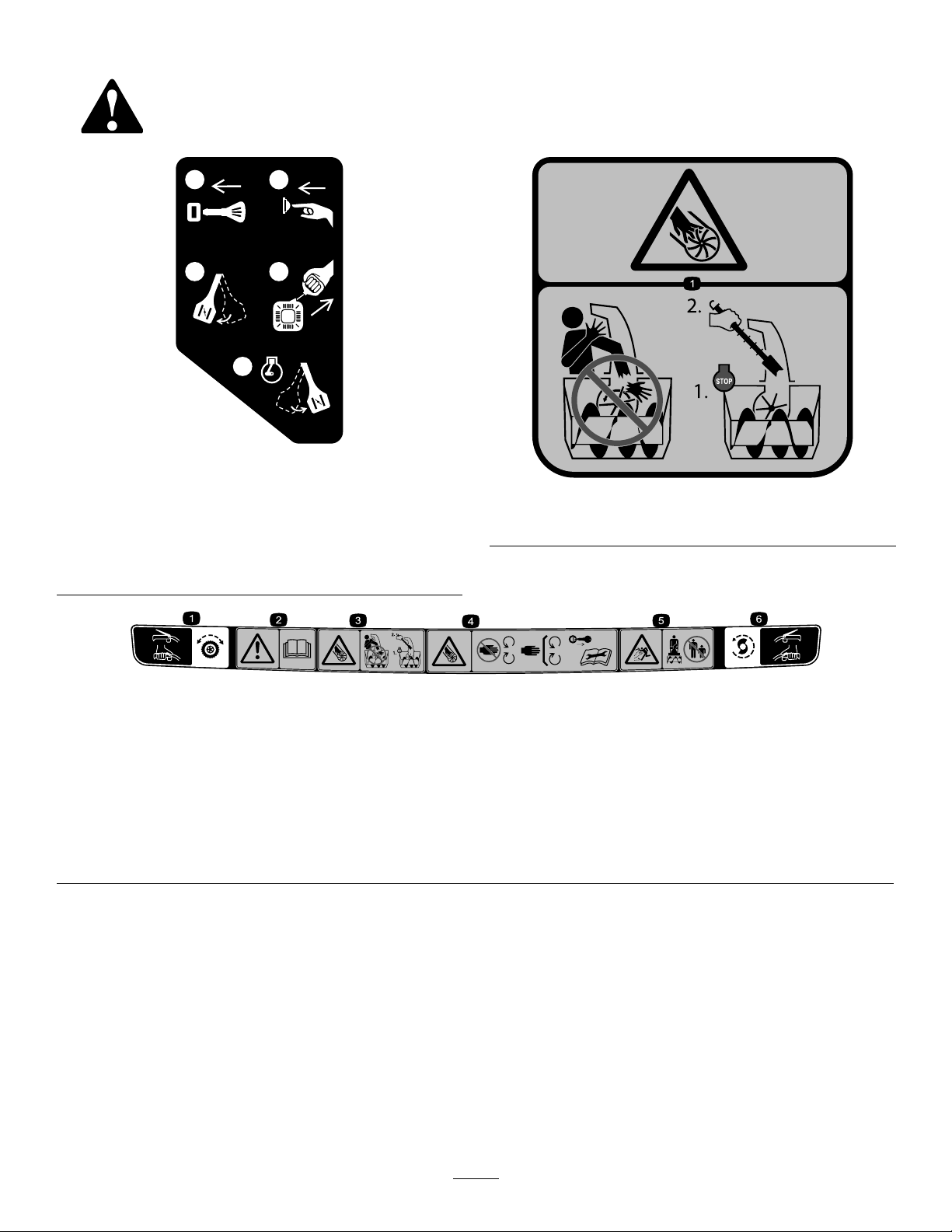
120-9805
1.Insertthekey.
2.Primetheengine3times.
3.Engagethechoke.
4.Pullthestartercord.
5.Oncetheengineisrunning,disengagethechoke.
OrderPartNo.121-1215
121-1239
121-1240
OrderPartNo.120-7194
1.Tractiondrive—squeezethelevertoengage;releasethe
levertodisengage.
2.Warning—readtheOperator’sManual.5.Thrownobjecthazard—keepbystandersasafedistance
3.Cutting/dismembermenthazard,impeller—donotplaceyour
handinthechute;shutofftheenginebeforeleavingthe
operatingposition,usethetooltoclearthechute.
4.Cuttingdismembermenthazard,impeller—keepaway
frommovingparts;removetheignitionkeyandreadthe
instructionsbeforeservicingorperformingmaintenance.
awayfromthesnowthrower.
6.Auger/impellerdrive—squeezethelevertoengage;release
thelevertodisengage.
3
Page 4
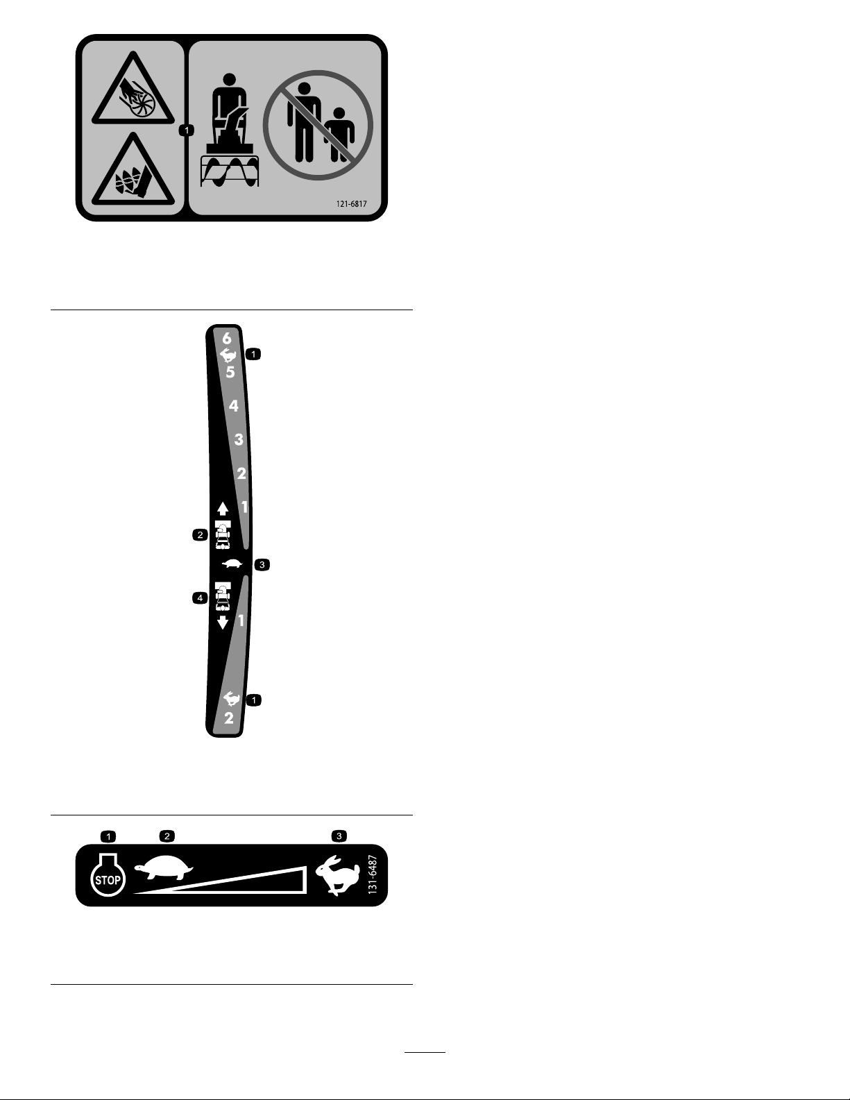
121-6817
1.Cuttingdismemberment,impellerandcutting
dismemberment,augerhazards—keepbystandersasafe
distanceawayfromthesnowthrower.
121-6823
1.Fast
2.Forwardspeeds4.Reversespeeds
3.Slow
131-6487
1.Engine—shutoff
2.Slow
3.Fast
4
Page 5
Setup
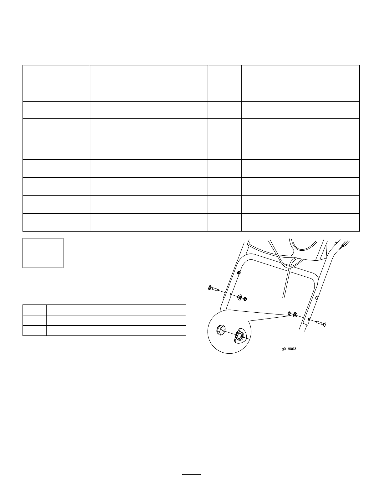
g019003
LooseParts
Usethechartbelowtoverifythatallpartshavebeenshipped.
ProcedureDescription
1
2
3
4
5
6
7
8
Handlebolt2
Curvedwasher
Locknut2
Hairpincotter2
Flatwasher3
Nut2
Carriagebolt
Flatwasher2
Carriagebolt
Locknut2
Nopartsrequired
Nopartsrequired
Nopartsrequired
Nopartsrequired
Qty.
Use
2
2
2
–
–
–
–
Installtheupperhandle.
Installthetraction-controllinkage.
Installthechute.
Installthechute-controlrod.
Checktheengine-oillevel.
Checkthetirepressure.
Checktheskidsandscraper.
Checktheoperationofthetractiondrive.
1
InstallingtheUpperHandle
Partsneededforthisprocedure:
2Handlebolt
2
Curvedwasher
2Locknut
Procedure
1.Liftandrotatetheupperhandleandpositionitover
thelowerhandle(Figure4).
2.Install2handlebolts,2curvedwashers,and2locknuts
inthelower-handleholes(Figure4).
Figure4
5
Page 6
2
g019004
g019378
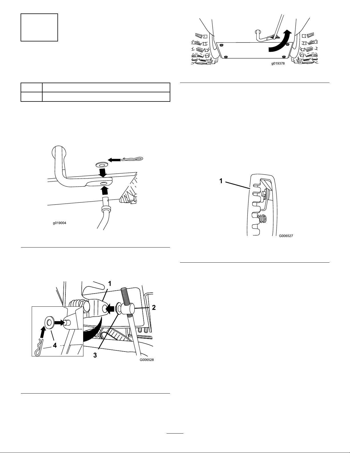
InstallingtheTraction-Control Linkage
Partsneededforthisprocedure:
Figure7
2Hairpincotter
3Flatwasher
Procedure
1.Insertthelowerendoftherodintothelowerlinkarm
sothatthebentendofthespeed-controlrodfaces
rearward(Figure5).
Figure5
2.Securethelowerendofthespeed-controlrodwitha
atwasherandahairpincotter(Figure5).
3.Placeaatwasheronthetrunnion(Figure6).
6.Pullupthespeed-controlrodandinsertthetrunnion
intotheholeinthespeed-selectorlever(Figure6).
Note:Ifthetrunniondoesnottintothehole
whenyouliftuponthespeed-controlrod,rotatethe
trunnionupwardordownwardonthespeed-control
roduntilitts.
7.Securethetrunnionandupperendofthespeed-control
rodwithawasherandahairpincotter.
Note:Foreasierinstallation,lookdownthroughthe
openinginthespeedselector(Figure8).
Figure8
1.Speedselector
Figure6
1.Speed-selectorlever
2.Trunnion
4.Shiftthespeed-selectorleverintoPositionR2.
5.Rotatethelowerlinkarmfullyupward
(counterclockwise)asshowninFigure7.
3.Innerwasher
4.Outerwasher
6
Page 7
3
3
1
2
g019379
4
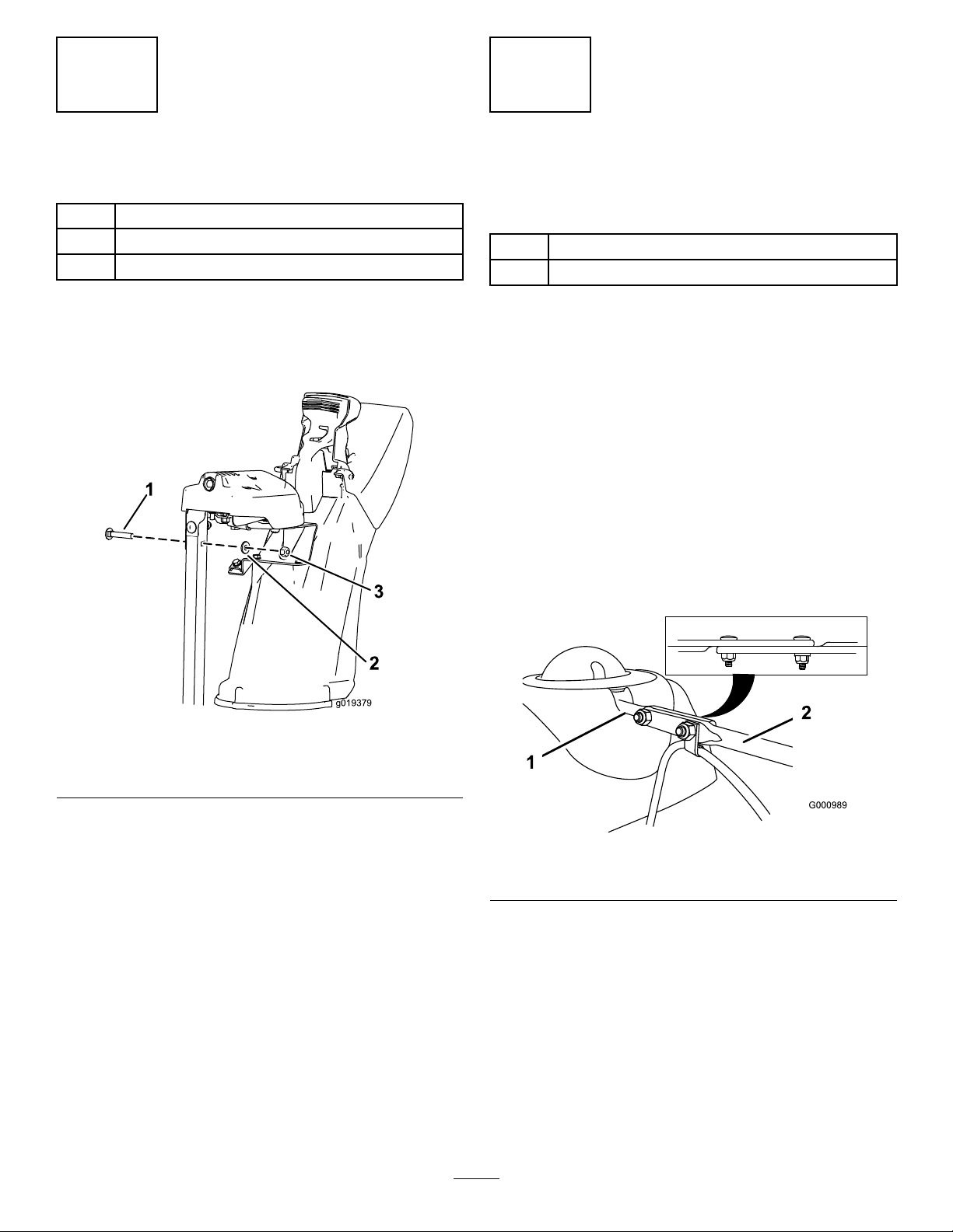
InstallingtheChute
Partsneededforthisprocedure:
2Nut
2
Carriagebolt
2Flatwasher
Procedure
1.Placethechuteontheframeandalignthedischarge
chutemounttothechutesupport.
InstallingtheChute-Control Rod
Partsneededforthisprocedure:
2
Carriagebolt
2Locknut
Procedure
1.UnwraptheQuickStickandrotateitsothatitis
uprightandinthecenter.
2.Holdthebluetriggercapdownandpulltheleverfully
rearward.
Note:Thedischargechuteanddeectorshouldface
forward.Iftheydonot,holdthebluetriggercap
down(butdonotmovetheQuickStick)androtatethe
dischargechuteuntiltheydo.
3.Aligntheattenedbackendofthelongchute-control
rodwiththeattenedfrontendoftheshortrod
thatextendsfromthecontrolpanelsothattheynest
together(Figure10).
Figure9
1.Carriagebolt
2.Flatwasher
2.Securethedischargechutemountusing2bolts,2nuts,
and2atwashers.
3.Nut
Figure10
1.Shortrod
4.Insertthefrontendoftherodintotheopeningin
thebackofthechute-gearcoveruntilitslidesintothe
chutegear(Figure11).
2.Longchute-controlrod
7
Page 8
g018885
Figure11
5
CheckingtheEngine-OilLevel
NoPartsRequired
Procedure
Note:Yourmachinecomeswithoilintheengine
crankcase.Beforestartingtheengine,checktheoillevel
andaddoilifnecessary.
RefertoCheckingtheEngine-OilLevel(page18).
5.Aligntheholesinthenestedendsoftherodsand
insert2carriagebolts(intheloose-partsbag)through
theshortrodfromtheleftsideofthemachine(from
theoperatingposition).
6.Insertthecableclipthatsupportsthedeectorcable
ontotheforwardcarriagebolt,andsecurethecarriage
boltswithlocknutsfromtheloose-partsbag(Figure
12).
Figure12
1.Cableclip2.Deectorcable
7.HoldthebluetriggercapdownandrotatetheQuick
Stickinacircletoensurethatthechuteanddeector
operatesmoothly.
6
CheckingtheTirePressure
NoPartsRequired
Procedure
Thetiresareoverinatedatthefactoryforshipping.Reduce
thepressureequallyinbothtirestobetween116and137
kPa(17and20psi).
7
CheckingtheSkidsand Scraper
NoPartsRequired
Procedure
RefertoCheckingandAdjustingtheSkidsandScraper(page
18).
8
Page 9

8
CheckingtheOperationofthe
TractionDrive
NoPartsRequired
4.Releasethetractionlever.
5.MovethespeedselectortothePosition1;referto
OperatingtheSpeedSelector(page14).
6.Squeezetheleft(traction)levertothehandgrip(Figure
13).
Themachineshouldmoveforward.Ifthemachine
doesnotmoveormovesrearward,completethe
following:
A.Releasethetractionleverandshutofftheengine.
Procedure
CAUTION
Ifthetractiondriveisnotproperlyadjusted,the
machinemaymoveinthedirectionoppositeof
whatyouintended,causinginjuryand/orproperty
damage.
Carefullycheckthetractiondriveandadjustit
properly,ifnecessary.
Note:Tochecktheoperationofthetractiondrive,youmust
engagetheself-propelfeaturebypinningthewheelsinthe
axle;refertoFreewheelingorUsingtheSelf-PropelDrive
(page11).
1.Starttheengine;refertoStartingtheEngine(page12).
2.MovethespeedselectortoPositionR1;referto
OperatingtheSpeedSelector(page14).
3.Squeezetheleft(traction)levertothehandgrip(Figure
13).
B.Disconnectthetrunnionfromthespeed-selector
lever(Figure6).
C.Turnthetrunnionupward(counterclockwise)on
thespeed-controlrod(Figure6).
D.Connectthetrunniontothespeed-selectorlever
(Figure6).
7.Ifyoumadeanyadjustments,repeatthisprocedure
untilnoadjustmentsarerequired.
Important:Ifthemachinemoveswhenthetraction
leverisinthereleasedposition,checkthetractioncable;
refertoCheckingandAdjustingtheTractionCable
(page19)ortakethemachinetoanAuthorizedService
Dealerforservice.
Figure13
Themachineshouldmoverearward.Ifthemachine
doesnotmoveormovesforward,completethe
following:
A.Releasethetractionleverandshutofftheengine.
B.Disconnectthetrunnionfromthespeed-selector
lever(Figure6).
C.Turnthetrunniondownward(clockwise)onthe
speed-controlrod(Figure6).
D.Connectthetrunniontothespeed-selectorlever
(Figure6).
9
Page 10

ProductOverview
g018887
ST
OP
1
2
3
4
5
6
7
G016500
Figure16
1.Snow-cleanouttool(attachedtothehandle)
Operation
BeforeOperation
Safety
•Useextensioncordsandreceptaclesasspeciedby
themanufacturerforallmachineswithelectric-starting
motors.
Figure14
1.Handgrip(2)
2.Auger/impellerlever10.Scraper
3.Speed-selectorlever
4.QuickStick™
discharge-chutecontrol
5.Tractionlever13.Electric-startbutton
6.Fuel-tankcap14.Electric-startplug-in
7.Oil-lltube/dipstick15.Snow-cleanouttool
8.Chutedeector
9.Dischargechute
11.Auger
12.Skid(2)
•Donotoperatethemachinewithoutwearingadequate
wintergarments.Avoidloose-ttingclothingthatcanget
caughtinmovingparts.Wearsubstantial,slip-resistant
footwearthatwillimprovefootingonslipperysurfaces.
•Alwayswearsafetyglassesoreyeprotectionduring
operationorwhileperforminganadjustmentorrepairto
protectyoureyesfromforeignobjectsthatthemachine
maythrow .
•Thoroughlyinspecttheareawhereyouwillusethe
machineandremovealldoormats,sleds,boards,wires,
andotherforeignobjects.
•Ifashield,safetydevice,ordecalisdamaged,illegible,or
lost,repairorreplaceitbeforebeginningoperation.Also,
tightenanyloosefasteners.
FillingtheFuelTank
•Forbestresults,useonlyclean,fresh,unleadedgasoline
withanoctaneratingof87orhigher((R+M)/2rating
method).
•Oxygenatedfuelwithupto10%ethanolor15%MTBE
byvolumeisacceptable.
Figure15
1.Primer5.Throttle
2.Ignitionswitch
3.Choke
4.Fuel-shutoffvalve
6.Oil-drainplug
7.Recoil-starthandle
•Donotuseethanolblendsofgasoline(suchasE15
orE85)withmorethan10%ethanolbyvolume.
Performanceproblemsand/orenginedamagemayresult
whichmaynotbecoveredunderwarranty.
•Donotusegasolinecontainingmethanol.
•Donotstorefueleitherinthefueltankorfuelcontainers
overthewinterunlessyouuseafuelstabilizer.
•Donotaddoiltogasoline.
Important:Toreducestartingproblems,addfuel
stabilizertothefuelallseason,mixingitwithgasoline
lessthan30daysold.
10
Page 11

Figure17
g019015
g019014
1.Donotllabovethebottomofthefuel-tankneck.
•Stayalertforhiddenhazardsortrafc.
•Afterstrikingaforeignobject,shutofftheengine,
removetheignitionkey,thoroughlyinspectthemachine
foranydamage,andrepairthedamagebeforestarting
andoperatingthemachine.
•Ifthemachineshouldstarttovibrateabnormally,shutoff
theengineandcheckimmediatelyforthecause.
•Donotruntheengineindoors,exceptwhenstarting
theengineandfortransportingthemachineinorout
ofthebuilding.Opentheoutsidedoors;exhaustfumes
aredangerous.
•Donotoverloadthemachinecapacitybyattemptingto
clearsnowattoofastarate.
•Nevertouchahotengineormufer.
•Thoroughlyinspecttheelectricalcordbeforeplugging
itintoapowersource.Ifthecordisdamaged,donot
useittostartthemachine.Replacethedamagedcord
immediately.Unplugthepowercordwheneveryouare
notstartingthemachine.
FreewheelingorUsingthe
DuringOperation
Safety
•Rotatingaugerbladescaninjurengersorhands.
Staybehindthehandlesandawayfromthedischarge
openingwhileoperatingthemachine.Keepyourface,
hands,feet,andanyotherpartofyourbodyor
clothingawayfrommovingorrotatingparts.
•Neverdirectthedischargetowardpeopleorareaswhere
propertydamagecanoccur.
•Exercisecautiontoavoidslippingorfalling.Alwaysbe
sureofyourfooting,andkeeparmholdonthehandles.
Walk;neverrun.
•Exerciseextremecautionwhenoperatingonslopes.
•Neveroperatethemachinewithoutgoodvisibilityor
light.
•Lookbehindandusecarewhenbackingupwiththe
machine.
•Whennotactivelyclearingsnow ,disengagepowertothe
rotorblades.
•Useextensioncordsandreceptaclesasspeciedby
themanufacturerforallmachineswithelectric-starting
motors.
•Donotattempttoclearsnowfromagravelorcrushed
rocksurface.Thisproductisintendedforuseonlyon
pavedsurfaces.
•Donotusethemachineonaroof.
•Neverattempttomakeanyadjustmentswhiletheengine
isrunning(exceptwhenspecicallyrecommendedby
manufacturer).
Self-PropelDrive
Youcanoperatethesnowthrowerwiththeself-propelfeature
engagedordisengaged(freewheeling).
Tofreewheel,slidethewheelsinwardandinserttheaxle
pinsthroughtheaxleholes,butnotthroughthewheelhubs
(Figure18).
Figure18
Toself-propel,inserttheaxlepinthroughtheholesinthe
wheelhubsandtheinner-axleholes(Figure19).
Figure19
11
Page 12

StartingtheEngine
G016512
1
G016498
g037221
1.Checktheengine-oillevel;refertoCheckingthe
Engine-OilLevel(page18).
2.Turnthefuel-shutoffvalve1/4turncounterclockwise
toopenit(Figure20).
4.Firmlypushintheprimerwithyourthumbasindicated
bythetablebelow,holdingtheprimerinforasecond
beforereleasingiteachtime(Figure22).
Temperature
Above-18°C(0°F)
-23°Cto-18°C(-10°Fto0°F)
Below-23°C(-10°F)
SuggestedNumberof
Primes
3
4
6
Figure20
3.Inserttheignitionkeyallthewayin(Figure21).
Figure22
1.Ignitionkey
Figure21
12
Page 13

5.MovethechoketotheCHOKEposition(Figure23).
G016501
STOP
G016504
g019055
Figure23
Figure25
1.Electric-startbutton3.Recoilstarter
2.Electric-startplug-in
Tousetheelectricstarter(electricstartonly),connecta
powercordtotheelectric-startplug-inrstandthen
toagroundfaultcircuitinterrupter(GFCI)power
outlet.UseonlyaUL-listed,16-gaugepowercord
recommendedforoutdoorusethatisnotlongerthan
15m(50ft).
Important:Donotuseawornordamagedpower
cord.
6.MovethethrottletotheFASTposition(Figure24).
Figure24
7.Startthemachinebypullingtherecoil-starthandleor
pressingtheelectric-startbutton(Figure25).
WARNING
Theelectricalcordcanbecomedamaged,
causingashockorre.
Thoroughlyinspecttheelectricalcordbefore
usingthemachine.Ifthecordisdamaged,do
notuseit.Replaceorrepairthedamagedcord
immediately.ContactanAuthorizedService
Dealerforassistance.
Important:Topreventdamagingtheelectric
starter,runitinshortcycles(5secondson,
5secondsoff),nomorethan10times.Ifthe
enginestilldoesnotstart,takethemachinetoan
AuthorizedServiceDealerforservice.
8.Disconnectthepowercordfromthepoweroutletrst
andthenfromthemachine(electricstartonly).
9.Allowtheenginetowarmup;graduallymovethe
choketowardtheRUNposition.Waitfortheengineto
runsmoothlybeforeeachchokeadjustment.
CAUTION
Ifyouleavethemachinepluggedintoa
poweroutlet,someonecaninadvertentlystart
themachineandinjurepeopleordamage
property.
Unplugthepowercordwheneveryouarenot
startingthemachine.
13
Page 14

ShuttingOfftheEngine
STOP
G016505
G016499
OperatingtheTractionDrive
1.MovethethrottletotheSLOWposition,andthento
theSTOPposition(Figure26)toshutofftheengine.
Youcanalsoshutofftheenginebypullingtheignition
keyoutwardtothemiddleposition.
Figure26
2.Waitforallmovingpartstostopbeforeleavingthe
operatingposition.
3.Removetheignitionkeytopreventaccidentalstarting.
CAUTION
Ifthetractiondriveisnotproperlyadjusted,the
machinemaymoveinthedirectionoppositeof
whatyouintended,causinginjuryand/orproperty
damage.
Carefullycheckthetractiondriveandadjustit
properly,ifnecessary;referto8Checkingthe
OperationoftheTractionDrive(page8)formore
information.
Important:Ifthemachinemoveswhenthetraction
leverisinthereleasedposition,checkthetractioncable;
refertoCheckingandAdjustingtheTractionCable
(page19)ortakethemachinetoanAuthorizedService
Dealerforservice.
Important:T ooperatethetractiondrive,youmust
operatethemachinewiththeself-propelfeature
engaged.RefertoFreewheelingorUsingtheSelf-Propel
Drive(page11).
1.Toengagethetractiondrive,squeezetheleft(traction)
levertothehandgrip(Figure28).
4.Closethefuel-shutoffvalvebyrotatingitclockwise
(Figure27).
Figure28
2.Tostopthetractiondrive,releasethetractionlever.
OperatingtheSpeedSelector
Thespeedselectorhas6forwardand2reversegears.
Tochangespeeds,releasethetractionleverandshiftthe
speed-selectorlevertothedesiredposition(Figure29).The
leverlocksinanotchateachspeedselection.
Figure27
5.Pulltherecoil-starthandle3or4times.
Note:Thishelpspreventtherecoilstarterfrom
freezingup.
Figure29
14
Page 15

OperatingtheAuger/Impeller
g018894
Drive
1.Toengagetheauger/impellerdrive,squeezetheright
(auger/impeller)levertothehandgrip(Figure30).
Figure30
Figure31
MovingtheDischargeChute
2.Tostoptheaugerandimpeller,releasetherightlever.
Important:Whenyouengageboththe
auger/impellerleverandthetractionlever,the
tractionleverlockstheauger/impellerleverdown,
freeingyourrighthand.Toreleasebothlevers,
simplyreleasetheleft(traction)lever.
3.Iftheaugerandimpellercontinuetorotatewhenyou
releasetheauger/impellerlever,donotoperatethe
machine.Checktheauger/impellercable;referto
CheckingandAdjustingtheAuger/ImpellerCable
(page19)andadjustitifnecessary.Otherwise,takethe
machinetoanAuthorizedDealerforservice.
WARNING
Iftheaugerandimpellercontinuetorotate
whenyoureleasetheauger/impellerlever,
donotoperatethemachine,asyoucould
seriouslyinjureyourselforothers.
TakeittoanAuthorizedServiceDealerfor
service.
HoldthebluetriggercapdownandmovetheQuickStick
tothelefttomovethedischargechutetotheleft;movethe
QuickSticktotherighttomovethedischargechutetothe
right(Figure32).
Figure32
OperatingtheQuickStick™
HoldthebluetriggercapdowntousetheQuickStickto
movethedischargechuteandthechutedeector.Releasethe
triggercaptolockthedischargechuteandchutedeector
intoposition(Figure31).
•Ifthechutedoesnotmove,refertoAdjustingthe
Discharge-ChuteLatch(page22).
•Ifthechutedoesnotturnasfartotheleftasitdoestothe
right,ensurethatthecableisroutedtotheinsideofthe
handles.Referto1InstallingtheUpperHandle(page5).
•Ifthechutedoesnotlockintoplacewhenyourelease
thetriggercap,refertoAdjustingtheDischarge-Chute
Latch(page22).
MovingtheChuteDeector
HoldthebluetriggercapdownandmovetheQuickStick
forwardtolowerthechutedeector;moveitrearwardtoraise
thechutedeector(Figure33).
15
Page 16

UncloggingtheDischarge Chute
Figure33
OperatingTips
DANGER
Whenthemachineisinoperation,theimpellerand
augerrotateandcaninjureoramputatehandsor
feet.
•Beforeadjusting,cleaning,inspecting,
troubleshooting,orrepairingthemachine,shut
offtheengineandwaitforallmovingparts
tostop.Disconnectthewirefromthespark
plugandkeepitawayfromtheplugtoprevent
someonefromaccidentallystartingtheengine.
•Removeanobstructionfromthedischarge
chute;refertoUncloggingtheDischargeChute.
Ifnecessary,usethesnow-cleanouttool,not
yourhands,toremoveanobstructionfromthe
dischargechute.
WARNING
Iftheauger/impellerisrunningbutthereisno
snowcomingoutofthedischargechute,the
dischargechutemaybeclogged.
Neveruseyourhandstoclearacloggeddischarge
chute.Thiscouldresultinpersonalinjury.
•Tounclogthedischargechute,stayintheoperating
positionandreleasetheleft(traction)lever.While
runningtheauger/impeller,pushdownonthehandlesto
raisethefrontofthemachineafewcentimeters(inches)
offthepavement.Thenliftthehandlesquicklytobump
thefrontofthemachineonthepavement.Repeatif
necessaryuntilastreamofsnowcomesoutthedischarge
chute.
•Ifyoucannotunclogthedischargechutebybumping
thefrontofthemachine,shutofftheengine,waitfor
allmovingpartstostop,andusethesnow-cleanout
tool;neveruseyourhand.
Important:Uncloggingthedischargechuteby
bumpingthefrontofthemachineonthepavement
maycausetheskidstomove.Adjusttheskidsand
tightentheskidboltssecurely.
•Staybehindthehandlesandawayfromthe
dischargeopeningwhileoperatingthemachine.
•Keepface,hands,feet,andanyotherpartof
yourbodyorclothingawayfromconcealed,
moving,orrotatingparts.
WARNING
Theimpellercanthrowstones,toys,andother
foreignobjectsandcauseseriouspersonalinjuryto
youorbystanders.
•Keeptheareatobeclearedfreeofallobjects
thattheaugercouldpickupandthrow.
•Keepallchildrenandpetsawayfromthearea
ofoperation.
•AlwayssetthethrottletotheFASTpositionwhen
throwingsnow .
•Iftheengineslowsdownunderaloadorthewheelsslip,
shiftthemachineintoalowergear.
•Ifthefrontofthemachineridesup,shiftthemachine
intoalowergear.Ifthefrontcontinuestorideup,lift
upthehandles.
AfterOperation
Safety
•Neverstorethemachinewithfuelinthefueltankinsidea
buildingwhereignitionsourcesarepresent,suchashot
waterheaters,spaceheaters,orclothesdryers.Allowthe
enginetocoolbeforestoringinanyenclosure.
•Whenstoringthemachineformorethan30days,referto
theStoragesectionforimportantdetails.
16
Page 17

PreventingFreeze-upafterUse
•Insnowyandcoldconditions,somecontrolsandmoving
partsmayfreeze.Donotuseexcessiveforcewhen
tryingtooperatefrozencontrols.Ifyouhavedifculty
operatinganycontrolorpart,starttheengineandletit
runforafewminutes.
•Afterusingthemachine,lettheenginerunforafew
minutestopreventmovingpartsfromfreezing.Engage
theauger/impellertoclearanyremainingsnowfrom
insidethehousing.RotatetheQuickSticktopreventit
fromfreezing.Shutofftheengine,waitforallmoving
partstostop,andremovealliceandsnowfromthe
machine.
•Withtheengineoff,pulltherecoil-starthandleseveral
timesandpushtheelectric-starterbuttononcetoprevent
therecoilandelectricstartersfromfreezingup.
Maintenance
Note:Determinetheleftandrightsidesofthemachinefromthenormaloperatingposition.
RecommendedMaintenanceSchedule(s)
MaintenanceService
Interval
Aftertherst2hours
Aftertherst5hours
Beforeeachuseordaily
Every100hours
Yearly
Yearlyorbeforestorage
Important:Youcanndmoreinformationaboutmaintainingandservicingyourmachineatwww.T oro.com.
MaintenanceSafety
MaintenanceProcedure
•Inspectthetractioncableandadjustitifnecessary.
•Inspecttheauger/impellercableandadjustitifnecessary.
•Changetheengineoil.
•Checktheengine-oillevelandaddoilifnecessary.
•Replacethesparkplug.
•Checktheskidsandscraperandadjustthemifnecessary .
•Inspectthetractioncableandadjustorreplaceitifnecessary.
•Inspecttheauger/impellercableandadjustorreplaceitifnecessary.
•Checktheauger-gearboxoilandaddoilifnecessary.
•Changetheengineoil.
•Lubricatethehexshaft.
•Checktheairpressureinthetiresandinatethemto1 16to137kPa(17to20psi).
•Drainthefuelandruntheenginetodryoutthefueltankandthecarburetoratthe
endoftheseason.
•HaveanAuthorizedServiceDealerinspectandreplacethetractiondrivebeltand/or
theauger/impellerdrivebelt,ifnecessary.
PreparingforMaintenance
Readthefollowingsafetyprecautionsbeforeperformingany
maintenanceonthemachine:
•Beforeperforminganymaintenance,service,or
adjustment,shutofftheengineandremovethekey.If
majorrepairsareeverneeded,contactanAuthorized
ServiceDealer.
•Checkallfastenersatfrequentintervalsforproper
tightnesstoensurethatthemachineisinsafeworking
condition.
•Maintainorreplacesafetyandinstructionlabels,as
necessary.
•Donotchangethegovernorsettingsontheengine.
•PurchaseonlygenuineTororeplacementpartsand
accessories.
1.Movethemachinetoalevelsurface.
2.Shutofftheengineandwaitforallmovingpartsto
stop.
3.Disconnectthespark-plugwire;referto.
17
Page 18

CheckingtheEngine-OilLevel
g019046
1
ServiceInterval:Beforeeachuseordaily—Checkthe
engine-oillevelandaddoilifnecessary.
1.Removethedipstick,wipeitclean,thenfullyinstall
thedipstick.
2.Removethedipstickandchecktheoillevel(Figure34).
IftheoillevelisbelowtheAddmarkonthedipstick,
addoil.RefertoChangingtheEngineOil(page20).
Figure35
1.3mm(1/8inch)
Important:Theaugerbladesmustbesupported
abovethegroundbytheskids.
3.Ensurethatthescraperis3mm(1/8inch)aboveand
paralleltoalevelsurface.
Note:Ifthepavementiscracked,rough,oruneven,
adjusttheskidstoraisethescraper.Forgravelsurfaces,
adjusttheskidsfurtherdowntopreventthemachine
frompickinguprocks.
Figure34
1.Full2.Addoil
CheckingandAdjustingthe SkidsandScraper
ServiceInterval:Yearly—Checktheskidsandscraperand
adjustthemifnecessary.
Checktheskidsandthescrapertoensurethattheaugerdoes
notcontactthepavedorgravelsurface.Adjusttheskidsand
thescraperasneededtocompensateforwear.
1.Checkthetirepressure;referto6CheckingtheTire
Pressure(page8).
2.Loosenthenutsthatsecurebothskidstotheauger
sidesuntiltheskidsslideupanddowneasily.
4.Movetheskidsdownuntiltheyareevenwiththe
ground.
5.Firmlytightenthenutsthatsecurebothskidstothe
augersides.
Note:Toquicklyadjusttheskidsiftheyloosen,
supportthescraper3mm(1/8inch)offthepavement,
thenadjusttheskidsdowntothepavement.
Note:Iftheskidsbecomeexcessivelyworn,youcan
turnthemoverandsettheunusedsidetowardthe
pavement.
18
Page 19

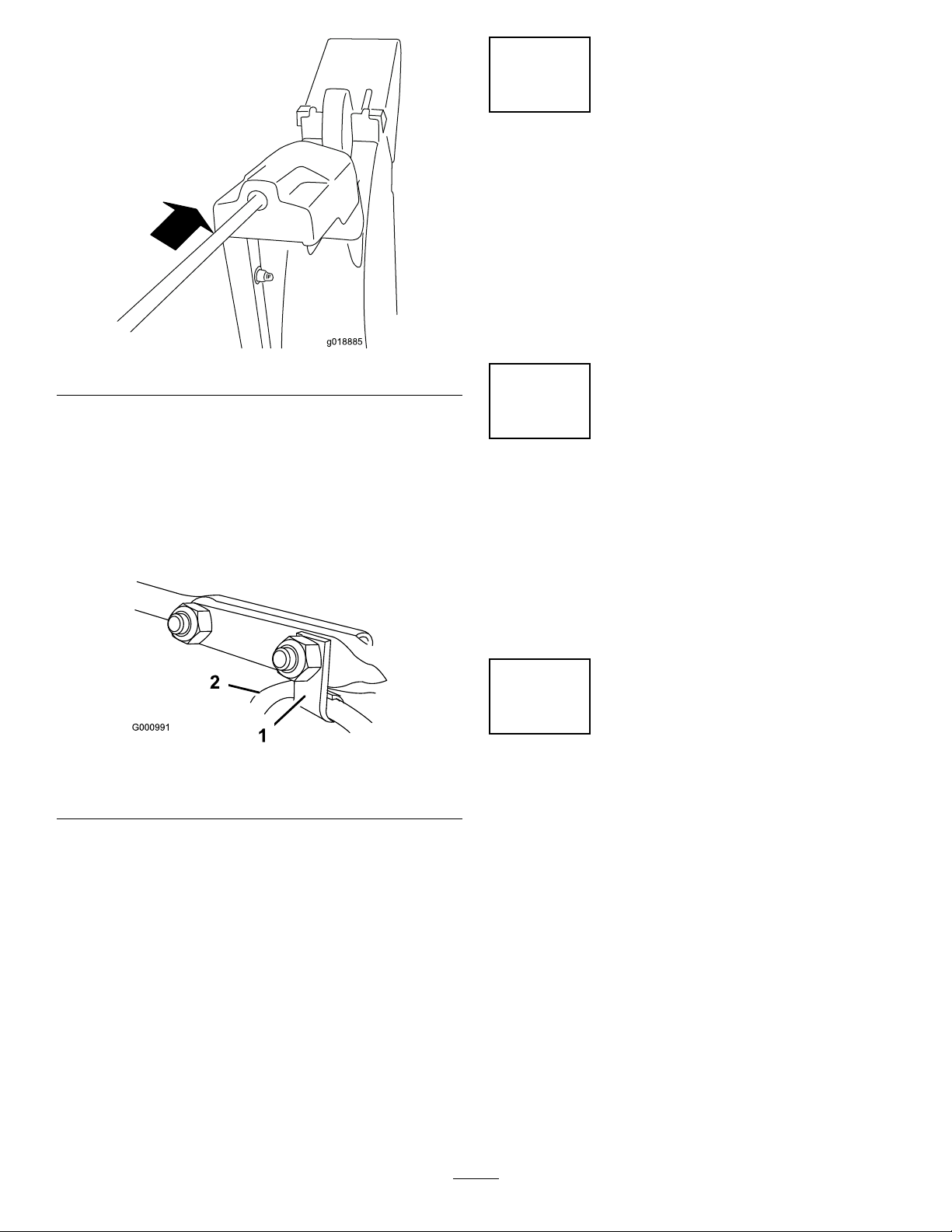
CheckingandAdjustingthe TractionCable
ServiceInterval:Aftertherst2hours—Inspectthe
tractioncableandadjustitifnecessary.
4.Tightenthejamnut(Figure37),ensuringthereisslight
tensiononthecable.
5.Ifthetractioncableisproperlyadjustedbutaproblem
remains,contactanAuthorizedServiceDealer.
Yearly—Inspectthetractioncableandadjustor
replaceitifnecessary.
Ifthemachinedoesnotdriveintheforwardorreversespeeds
oritdriveswhenyoureleasethetractionlever,adjustthe
tractioncable.
Iftheleft(traction)cableisnotproperlyadjusted,dothe
followingsteps:
1.Loosenthejamnut.
2.Engagethetractionleverandholditinplace(Figure
36).
Figure36
CheckingandAdjustingthe Auger/ImpellerCable
ServiceInterval:Aftertherst2hours—Inspectthe
auger/impellercableandadjustitif
necessary.
Yearly—Inspecttheauger/impellercableandadjust
orreplaceitifnecessary.
1.Loosenthejamnut.
2.Engagetheauger/impellerleverandholditinplace
(Figure38).
Figure38
3.Loosenortightentheturnbuckletoadjustspring
lengthto5.5cm(2.18inches)(Figure37).
Figure37
1.Jamnut
2.Turnbuckle
3.Spring
4.5.5cm(2.18inches)
3.Loosenortightentheturnbuckletoadjustthespring
lengthto7cm(2.75inches)asshowninFigure39.
Figure39
1.Jamnut
2.Turnbuckle
4.Tightenthejamnut(Figure39),ensuringthereisslight
tensiononthecable.
3.Spring
4.7cm(2.75inches)
19
Page 20

5.Iftheauger/impellercableisproperlyadjustedbut
g019049
aproblemremains,contactanAuthorizedService
Dealer.
Checkingthe Auger-Gearbox-OilLevel
ServiceInterval:Yearly—Checktheauger-gearboxoiland
addoilifnecessary.
1.Movethemachinetoalevelsurface.
2.Cleantheareaaroundthepipeplug(Figure40).
Figure41
EngineOilCapacities
Figure40
3.Removethepipeplugfromthegearbox.
4.Checktheoillevelinthegearbox.Theoilshouldbe
3/8inch(9.5mm)belowthelleropening.
5.Iftheoillevelislow,addGL-5orGL-6,SAE80-90
EPgearoillubricanttothegearboxuntiltheoillevel
is3/8inchbelowthelleropening.
Note:Donotusesyntheticoil.
6.Installthepipepluginthegearbox.
ChangingtheEngineOil
ServiceInterval:Aftertherst5hours—Changetheengine
oil.
Yearly—Changetheengineoil.
Ifpossible,runtheenginejustbeforechangingtheoilbecause
warmoilowsbetterandcarriesmorecontaminants.
Model
37779
37780
EngineOilCapacity
0.50L(17oz)
0.70L(24oz)
1.Cleantheareaaroundtheoil-draincap(Figure42).
Figure42
1.Oil-draincap
2.Slideanoil-drainpanunderthedrainextensionand
removetheoil-draincap.
3.Draintheoil.
Note:Disposeoftheusedoilproperlyatalocal
recyclingcenter.
4.Installtheoil-draincap.
5.Fillthecrankcasewithoil.
A.Removethedipstickandslowlypouroilintothe
oil-lltubetoraisetheoilleveltotheFullmark
onthedipstick(Figure44).Donotoverll.
UseautomotivedetergentoilwithanAPIserviceclassication
ofSF,SG,SH,SJ,SL,orhigher.
UseFigure41belowtoselectthebestoilviscosityforthe
outdoortemperaturerangeexpected:
20
Page 21

g037222
1
2
Figure43
g019018
g019019
1
1.Full2.Addoil
B.Installthedipsticksecurely.
Note:Donotspilloilaroundtheoil-lltube;
oilcouldleakontotractionpartsandcausethe
tractiontoslip.
LubricatingtheHexShaft
ServiceInterval:Y early—Lubricatethehexshaft.
2.Tipthemachineforwardontoitsaugerhousingand
blockitsothatitcannotfall.
3.Removethebackcover(Figure45).
Figure45
1.Screws
4.Movethespeed-selectorlevertoPositionR2.
5.Dipyourngerinengineoilandlightlylubricatethe
hexshaft.
6.Movethespeed-selectorlevertoPosition6.
7.Lubricatetheotherendofthehexshaft.
8.Movethespeed-selectorleverforwardandrearward
afewtimes.
9.Installthebackcoverandreturnthemachinetothe
operatingposition.
Lightlylubricatethehexshaftyearlywithautomotiveengine
oil(Figure44).
Figure44
1.Hexshaft
2.Steelfrictionpulley
3.Rubberwheel
Important:Donotgetoilontherubberwheelorthe
steelfrictionpulleybecausethetractiondrivewillslip
(Figure44).
1.Drainthefuelfromthefueltank.
ReplacingtheSparkPlug
ServiceInterval:Every100hours—Replacethesparkplug.
WARNING
Replacingthesparkplugwhiletheengineishot
canresultinburns.
Waituntiltheengineiscooltoreplacethespark
plug.
UseaT orosparkplugorequivalent(Champion®RN9YCor
NGKBPR6ES).
1.Removetheboot(Figure46).
21
Page 22

G016645
1
Figure46
G016646
g019021
1
2
3
1.Spark-plugboot
2.Cleanaroundthebaseofthesparkplug.
AdjustingtheDischarge-Chute Latch
Ifthedischargechutedoesnotlockintothedesiredposition
ordoesnotunlocksothatyoucanmoveittoanother
position,adjustthedischarge-chutelatch.
1.Loosentheclampfasteneronthechute-supportplate
untilthecableisfree.
Figure47
3.Removeanddiscardtheoldsparkplug.
Note:Y ouwillneedaratchetwrenchextensionto
removethesparkplug.
4.Setthegapbetweentheelectrodesonanewsparkplug
at0.76mm(0.030inch)asshowninFigure48.
Figure48
1.0.76mm(0.030inch)
Figure49
1.Cableconduit3.Clampfastener
2.Cableclamp
2.Removeanyslackinthecablebypullingthecable
conduitrearward.
3.Tightentheclampfastenerwhileholdingthecablein
place.
ReplacingtheDriveBelts
Iftheauger/impellerdrivebeltorthetractiondrivebelt
becomesworn,oil-soaked,orotherwisedamaged,havean
AuthorizedServiceDealerreplacethebelt.
5.Installthenewsparkplug,tightenitrmly,andattach
theignitionwiretothesparkplug.
Note:Ensuretheignitionwiresnapscompletelyinto
placeonthesparkplug.
22
Page 23

Storage
WARNING
•Fuelvaporscanexplode.
•Donotstorefuelmorethan30days.
•Donotstorethemachineinanenclosurenear
anopename.
•Allowtheenginetocoolbeforestoringit.
PreparingtheMachinefor Storage
1.Onthelastrefuelingoftheyear,addfuelstabilizerto
freshfuelasdirectedbytheenginemanufacturer.
Note:Fuelshouldnotbestoredlongerthansuggested
bythefuelstabilizermanufacturer.
2.Runtheenginefor10minutestodistributethe
conditionedfuelthroughthefuelsystem.
3.Runthemachineuntiltheenginerunsoutoffuel.
4.Primetheengineandstartitagain.
5.Allowtheenginetorununtilitshutsoff.Whenyou
cannolongerstarttheengine,itissufcientlydry.
6.Shutofftheengineandallowittocool.
7.Removetheignitionkey.
8.Cleanthemachinethoroughly.
9.Touchupchippedsurfaceswithpaintavailablefroman
AuthorizedServiceDealer.Sandaffectedareasbefore
painting,andusearustpreventativetopreventthe
metalpartsfromrusting.
10.Tightenallloosescrews,bolts,andlocknuts.Repairor
replaceanydamagedparts.
11.Coverthemachineandstoreitinaclean,dryplaceout
ofthereachofchildren.
RemovingtheMachinefrom Storage
1.Removethesparkplugandspintheenginerapidly
usingthestartertoblowtheexcessoilfromthe
cylinder.
2.Installthesparkplugandtightenitrmly.
3.Connectthespark-plugwire.
4.Performtheannualmaintenanceproceduresasgiven
intheRecommendedMaintenanceSchedule;referto
Maintenance(page17).
23
Page 24

Troubleshooting
Problem
Theelectricstarterdoesnotturn(electric
startonly).
Theenginedoesnotstartorstartshard.
PossibleCauseCorrectiveAction
1.Thepowercordisdisconnectedatthe
outletorthemachine.
2.Thepowercordisworn,corroded,or
damaged.
3.Thepoweroutletisnotenergized.
1.Thekeyisnotintheignitionorisinthe
STOPposition.
2.ThechokeisintheOFFpositionand
theprimerhasnotbeenpressed.
3.Thefuel-shutoffvalveisnotopen.3.Openthefuel-shutoffvalve.
4.ThethrottleisnotintheFASTposition.4.MovethethrottletotheFASTposition.
5.Thefueltankisemptyorthefuel
systemcontainsstalefuel.
6.Thespark-plugwireislooseor
disconnected.
7.Thesparkplugispitted,fouled,orthe
gapisincorrect.
8.Thefuel-ventcapisrestricted.
9.Theengine-oillevelintheengine
crankcaseistoolowortoohigh.
1.Connectthepowercordtotheoutlet
and/orthemachine.
2.Replacethepowercord.
3.Haveaqualiedelectricianenergize
theoutlet.
1.Insertthekeyintotheignitionandturn
ittotheONposition.
2.MovethechoketotheONpositionand
presstheprimer3times.
5.Drainand/orllthefueltankwith
freshfuel(notmorethan30daysold).
Iftheproblempersists,contactan
AuthorizedServiceDealer.
6.Connectthewiretothesparkplug.
7.Checkthesparkplugandadjustthe
gapifnecessary .Replacethespark
plugifitispitted,fouled,orcracked.
8.Removetheventrestrictionorreplace
thefuelcap.
9.Addordrainoiltoadjusttheoillevelin
theenginecrankcasetotheFullmark
onthedipstick.
Theenginerunsrough.
1.ThechokeisintheONposition.1.MovethechoketotheOFFposition.
2.Thefuel-shutoffvalveisnotcompletely
open.
3.Thefueltankisnearlyemptyor
containsstalefuel.
4.Thespark-plugwireisloose.
5.Thesparkplugispitted,fouled,orthe
gapisincorrect.
6.Theengine-oillevelintheengine
crankcaseistoolowortoohigh.
2.Openthefuel-shutoffvalve.
3.Drainandllthefueltankwithfresh
fuel(notmorethan30daysold).
Iftheproblempersists,contactan
AuthorizedServiceDealer.
4.Connectthewiretothesparkplug.
5.Checkthesparkplugandadjustthe
gapifnecessary .Replacethespark
plugifitispitted,fouled,orcracked.
6.Addordrainoiltoadjusttheoillevelin
theenginecrankcasetotheFullmark
onthedipstick.
24
Page 25

Problem
PossibleCauseCorrectiveAction
Theengineruns,butthemachine
dischargessnowpoorlyornotatall.
Thedischargechuteeitherdoesnotlock
intoplaceordoesnotmove.
Themachinedoesnotproperlyclearthe
snowoffthesurface.
1.ThethrottleisnotintheFASTposition
whenthrowingsnow .
2.Themachineismovingtoofasttoclear
thesnow.
3.Y ouaretryingtoremovetoomuch
snowperswath.
4.Y ouaretryingtoremoveextremely
heavyorwetsnow.
5.Thedischargechuteisplugged.5.Unclogthedischargechute.
6.Theauger/impellerdrivebeltisloose
orisoffthepulley .
7.Theauger/impellerdrivebeltisworn
orbroken.
1.Thedischarge-chutelatchisnot
properlyadjusted.
1.Theskidsand/orscraperarenot
properlyadjusted.
2.Thepressureinthetiresisnotequal.
1.MovethethrottletotheFASTposition.
2.Shiftthemachineintoalowergear.
3.Reducetheamountofsnowremoved
perswath.
4.Don'toverloadthemachinewith
extremelyheavyorwetsnow.
6.Installand/oradjusttheauger/impeller
drivebelt;refertowww.T oro.com
forservicinginformationortakethe
machinetoanAuthorizedService
Dealer.
7.Replacetheauger/impellerdrivebelt;
refertowww.T oro.comforservicing
informationortakethemachinetoan
AuthorizedServiceDealer.
1.Adjustthedischarge-chutelatch.
1.Adjusttheskidsand/orthescraper.
2.Checkandadjustthepressureinone
orbothtires.
25
Page 26

EmissionControlWarrantyStatement
FortheUnitedStates,California,andCanada
YourWarrantyRightsandObligations
TheCaliforniaAirResourcesBoard(CARB),theU.S.EnvironmentalProtectionAgency(EPA),andTheT oroCompany,arepleasedtoexplainthe
emissioncontrolsystemwarrantyonyour2017–2018smalloff-roadengine/equipment.InCaliforniaandtheUnitedStates,newsmalloff-road
engines/equipmentmustbedesigned,built,andcertiedtomeetstringentanti-smogstandards.TheToroCompanywarrantstheemissioncontrol
systemonyoursmalloff-roadengine/equipmentfortheperiodoftimelistedbelow,providedtherehasbeennoabuse,neglect,orimpropermaintenance
ofyoursmalloff-roadengine/equipment.
Youremissioncontrolsystemmayincludepartssuchasthecarburetor,fuel-injectionsystem,theignitionsystem,catalyticconverter,fueltanks,fuellines,
fuelcaps,valves,canisters,lters,vaporhoses,clamps,connectors,andotherassociatedemission-relatedcomponents.
Whereawarrantableconditionexists,TheT oroCompanywillrepairyoursmalloff-roadengine/equipmentatnocosttoyouincludingdiagnosis,
partsandlabor.
Manufacturer’sWarrantyCoverage
ThisemissioncontrolsystemiswarrantedfortwoyearsorthedurationofTheToroWarranty,whicheverislonger.Ifanyemission-relatedpartonyour
engine/equipmentisdefective,thepartwillberepairedorreplacedbyTheT oroCompany.
OwnerResponsibilities
Asthesmalloff-roadengineowner,youareresponsiblefortheperformanceoftherequiredmaintenancelistedinyourOperator'sManual.Werecommend
thatyouretainallreceiptscoveringmaintenanceonyoursmalloff-roadengine/equipment,butwecannotdenywarrantysolelyforthelackofreceipts.
Asthesmalloff-roadengine/equipmentowner ,youshouldhoweverbeawarethatwemaydenyyouwarrantycoverageifyoursmalloff-road
engine/equipmentoraparthasfailedduetoabuse,neglect,impropermaintenanceorunapprovedmodications.
Youareresponsibleforpresentingyoursmalloff-roadengine/equipmenttoaT oroDistributionCenterorServiceCenterassoonasaproblemexists.The
warrantyrepairsshouldbecompletedinareasonableamountoftime,nottoexceedthirty(30)days.
Ifyouhaveanyquestionsregardingyourwarrantycoverage,contactusat:
CustomerCareDepartment,ConsumerDivision
ToroWarrantyCompany
811 1LyndaleAvenueSouth
Bloomington,MN55420-1196
1-888-384-9939(U.S.andCanadiancustomers)
emailCustomerSupportat:www.toro.com
*374-0320*
GeneralEmissionsWarrantyCoverage
TheT oroCompanywarrantstotheultimatepurchaserandeachsubsequentpurchaserthatthesmalloff-roadengine/equipmentis:
•Designed,built,andcertiedtoconformwithallapplicableemissionsregulations;and
•Freefromdefectsinmaterialsandworkmanshipthatcouldcausethefailureofawarrantedpart;and
•Identicalinallmaterialrespectstothepartsasdescribedintheapplicationforcertication.
Thewarrantyperiodbeginsonthedatethesmalloff-roadengine/equipmentisdeliveredtoanultimatepurchaser.Thewarrantedperiodistwoyearsor
thedurationofTheToroWarranty,whicheverislonger.
Subjecttocertainconditionsandexclusionsasstatedbelow,thewarrantyonevaporativeemissions-relatedpartsisasfollows:
1.Anywarrantedpartthatisnotscheduledforreplacementasrequiredmaintenanceinthewritteninstructionssupplied,iswarranted
forthewarrantyperiodstatedabove.Ifthepartfailsduringtheperiodofwarrantycoverage,thepartwillberepairedorreplacedby
TheT oroCompany .Anysuchpartrepairedorreplacedunderwarrantywillbewarrantedfortheremainderofthewarrantyperiod.
2.Anywarrantedpartthatisscheduledonlyforregularinspectioninthewritteninstructionssuppliediswarrantedforthewarranty
periodstatedabove.Anysuchpartrepairedorreplacedunderthewarrantywillbewarrantedfortheremainderofthewarrantyperiod.
3.Anywarrantedpartthatisscheduledforreplacementasrequiredmaintenanceinthewritteninstructionssuppliedis
warrantedfortheperiodoftimebeforetherstscheduledreplacementdateforthatpart.Ifthepartfailsbeforetherst
scheduledreplacement,thepartwillberepairedorreplacedbyTheToroCompany .Anysuchpartrepairedorreplaced
underwarrantywillbewarrantedfortheremainderoftheperiodpriortotherstscheduledreplacementpointforthepart.
4.Repairorreplacementofanywarrantedpartunderthewarrantyprovisionshereinmustbeperformedatan
AuthorizedServiceDealeratnochargetotheowner.
5.WarrantyservicesorrepairswillbeprovidedatallServiceDealersauthorizedtoservicethesubjectenginesorequipment.
6.Thesmalloff-roadengine/equipmentownerwillnotbechargedfordiagnosticlaborthatisdirectlyassociatedwithdiagnosis
ofadefective,emission-relatedwarrantedpart,providedthatsuchdiagnosticworkisperformedatanAuthorizedServiceDealer.
7.TheToroCompanyisliablefordamagestootherengine/equipmentcomponentscausedbyafailureunderwarrantyofanywarrantedpart.
8.Throughoutthesmalloff-roadengine/equipmentwarrantyperiodstatedabove,TheToroCompanywillmaintainasupply
ofwarrantedpartssufcienttomeettheexpecteddemandforsuchparts.
9.Manufacturerapprovedreplacementpartsmaybeusedintheperformanceofanywarrantymaintenanceorrepairsand
mustbeprovidedwithoutchargetotheowner.SuchusewillnotreducethewarrantyobligationsofTheT oroCompany .
10.Add-onormodiedpartsthatarenotapprovedbyTheT oroCompanymaynotbeused.Theuseofanon-approvedadd-onormodiedpartsby
thepurchaserwillbegroundsfordisallowingawarrantyclaim.TheT oroCompanywillnotbeliabletowarrantfailuresofwarrantedpartscausedby
theuseofannon-approvedadd-onormodiedparts.
374-0320RevA
Page 27

WarrantedParts
Thefollowingemissionwarrantypartsarecovered,totheextentthesepartswerepresentontheT oroengine/equipmentand/orT orosuppliedfuelsystem:
1.FuelSystemParts
•Carburetorandinternalparts
•Coldstartingenrichment(primerorchoke)
•Fuelpump
•Fuelline,ttings,andclamps
•Fueltank,cap,andtether
•Carboncanister
2.AirInductionSystem
•Aircleaner
•Intakemanifold
•Crankcaseventandline(s)
•Purgelineandttings
3.IgnitionSystem
•Sparkplug(s)andwire(s)
•Magnetoignitionsystem
4.CatalyticExhaustSystem
•Catalyticconverter
•Exhaustmanifold
•Airinjectorsystemandvalve(s)
5.MiscellaneousItemsUsedinEmissionControlSystem
•Valves,switches,andlinkages
•Connectors,ttings,andbrackets
374-0320RevA
Page 28

AThree-YearLimitedWarranty(45DayLimitedWarrantyforCommercialUse)
TheToroWarranty
SnowMaster
PowerMax
ConditionsandProductsCovered
TheToroCompanyanditsafliate,ToroWarrantyCompany,pursuantto
anagreementbetweenthem,jointlypromisetorepairtheT oroProduct
listedbelowifusedforresidentialpurposes*,ifdefectiveinmaterialsor
workmanshiporifitstopsfunctioningduetothefailureofacomponent
fortheperiodlistedbelow.
Thiswarrantycoversthecostofpartsandlabor,butyoumustpay
transportationcosts.
Thefollowingtimeperiodsapplyfromtheoriginaldateofpurchase:
ProductsWarrantyPeriod
SnowMasterandPowerMaxSnowthrowers
andAttachments
—ChuteLifetime(originalowner
—DeectorLifetime(originalowner
—SnowMasterLowerChuteLifetime(originalowner
—PowerMaxAnti-CloggingSystem(Plastic
impellerhousingcover)
3years
only)
only)
only)
Lifetime(originalowner
only)
LimitedWarrantyforCommercialUse
Gas-poweredT oroProductsusedforcommercial,institutional,orrental
use,arewarrantedfor45daysagainstdefectsinmaterialsorworkmanship.
Componentsfailingduetonormalweararenotcoveredbythiswarranty .
InstructionsforObtainingWarrantyService
IfyouthinkthatyourToroProductcontainsadefectinmaterialsor
workmanship,followthisprocedure:
1.ContactanyAuthorizedToroServiceDealertoarrangeserviceattheir
dealership.Tolocateadealerconvenienttoyou,refertotheYellow
Pagesofyourtelephonedirectory(lookunder“LawnMowers”)or
accessourwebsiteatwww.Toro.com.Youmayalsocallthenumbers
listedinitem#3tousethe24-hourToroDealerlocatorsystem.
2.Bringtheproductandyourproofofpurchase(salesreceipt)tothe
ServiceDealer.Thedealerwilldiagnosetheproblemanddetermineif
itiscoveredunderwarranty.
3.IfforanyreasonyouaredissatisedwiththeServiceDealer’s
analysisorwiththeassistanceprovided,contactusat:
ToroW arrantyCompany
CustomerCareDepartment,RLCDivision
811 1LyndaleAvenueSouth
Bloomington,MN55420-1196
Tollfreeat866-336-5205(U.S.customers)
Tollfreeat866-854-9033(Canadiancustomers)
OwnerResponsibilities
YoumustmaintainyourT oroProductbyfollowingthemaintenance
proceduresdescribedintheOperator'sManual.Suchroutinemaintenance,
whetherperformedbyadealerorbyyou,isatyourexpense.
ItemsandConditionsNotCovered
Thereisnootherexpresswarrantyexceptforspecialemissionsystem
coverageandenginewarrantycoverageonsomeproducts.Thisexpress
warrantydoesnotcoverthefollowing:
•Costofregularmaintenanceserviceorreplacementofwearparts,
suchasblades,rotorblades(paddles),scraperblades,belts,fuel,
lubricants,oilchanges,sparkplugs,lightbulbs,cable/linkageorbrake
adjustments
•Anyproductorpartwhichhasbeenalteredormisusedorneglected
orrequiresreplacementorrepairduetoaccidentsorlackofproper
maintenance
•Pickupanddeliverycharges
•Operationalmisuse,neglect,oraccidents
•RepairsorattemptedrepairsbyanyoneotherthananAuthorizedToro
ServiceDealer
•Repairsnecessaryduetofailuretofollowrecommendedfuel
procedure(consultOperator'sManualformoredetails)
–Removingcontaminantsfromthefuelsystemisnotcovered
–Useofoldfuel(morethanonemonthold)orfuelwhichcontains
morethan10%ethanolormorethat15%MTBE
–Failuretodrainthefuelsystempriortoanyperiodofnon-use
overonemonth
GeneralConditions
AllrepairscoveredbythesewarrantiesmustbeperformedbyanAuthorized
ToroServiceDealerusingToroapprovedreplacementparts.Repairbyan
AuthorizedToroServiceDealerisyoursoleremedyunderthiswarranty .
NeitherTheToroCompanynorToroW arrantyCompanyisliablefor
indirect,incidental,orconsequentialdamagesinconnectionwiththe
useoftheToroProductscoveredbythesewarranties,includingany
costorexpenseofprovidingsubstituteequipmentorserviceduring
reasonableperiodsofmalfunctionornon-usependingcompletionof
repairsunderthesewarranties.
Allimpliedwarrantiesofmerchantability(thattheproductistforordinary
use)andtnessforuse(thattheproductistforaparticularpurpose)are
limitedtothedurationoftheexpresswarranty.
Somestatesdonotallowexclusionsofincidentalorconsequential
damages,orlimitationsonhowlonganimpliedwarrantylasts,sotheabove
exclusionsmaynotapplytoyou.
Thiswarrantygivesyouspeciclegalrights,andyoumayalsohaveother
rightswhichvaryfromstatetostate.
CountriesOtherthantheUnitedStatesorCanada
CustomerswhohavepurchasedT oroproductsexportedfromtheUnitedStatesorCanadashouldcontacttheirT oroDistributor(Dealer)toobtain
guaranteepoliciesforyourcountry,province,orstate.IfforanyreasonyouaredissatisedwithyourDistributor'sserviceorhavedifcultyobtaining
guaranteeinformation,contacttheToroimporter.Ifallotherremediesfail,youmaycontactusatToroWarrantyCompany.
AustralianConsumerLaw
AustraliancustomerswillnddetailsrelatingtotheAustralianConsumerLaweitherinsidetheboxoratyourlocalT oroDealer.
*Residentialpurposesmeansuseoftheproductonthesamelotasyourhome.Useatmorethanonelocation,orinstitutionalorrentaluse,isconsidered
commercialuse,andthecommercialusewarrantywouldapply.
374-0314RevB
 Loading...