

Page 1
Part No. 15213SL
Service Manual
Preface
The purpose of this publication is to provide the service
technician with service information for service and
repair of major systems and components on the
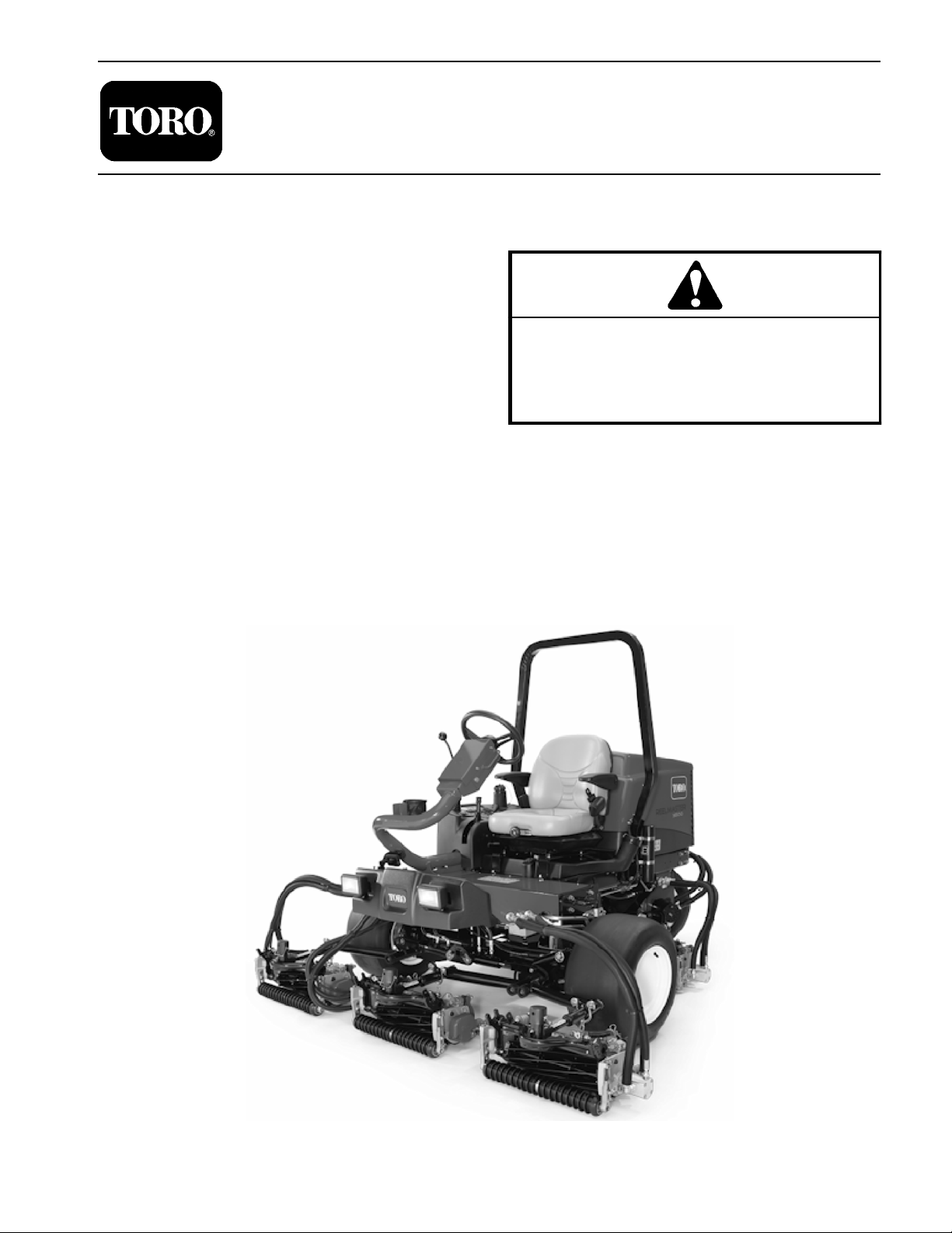
Reelmaster 3550- D.
REFER TO THE TRACTION UNIT AND CUTTING
UNIT OPERATOR’S MANUALS FOR OPERATING,
MAINTENANCE AND ADJUSTMENT INSTRUCTIONS. Copies of the Operator’s Manuals and Parts
Catalog are available on the internet at www.Toro.com.
The ToroCompany reserves the right to changeproduct
specifications or this publication without notice.
Reelmaster
This safety symbol means DANGER, WARNING
or CAUTION, PERSONAL SAFETY INSTRUCTION. When you see this symbol, carefully read
the instructions that follow. Failure to obey the
instructions may result in personal injury.
NOTE: A NOTE will give general information about the
correct operation, maintenance, service, testing or repair of the machine.
IMPORTANT: The IMPORTANT notice will give important instructions which must be followed to prevent damage to systems or components on the
machine.
3550- D
R
EThe Toro Company - 2015
Page 2

This page is intentionally blank.
Reelmaster 3550- D
Page 3

Table Of Contents
Chapter 1 - Safety
General Safety Instructions 1 - 2..................
Jacking Instructions 1 - 4.........................
Safety and Instruction Decals 1 - 5................
Chapter 2 - Product Records and Maintenance
Product Records 2 - 1...........................
Maintenance 2 - 1...............................
Equivalents and Conversions 2 - 2................
Torque Specifications 2 - 3.......................
Chapter 3 - Kubota Diesel Engine
Specifications 3 - 3..............................
General Information 3 - 4........................
Service and Repairs 3 - 6........................
KUBOTA WORKSHOP MANUAL, DIESEL ENGINE,
05 SERIES
Chapter 4 - Hydraulic System
Specifications 4 - 2..............................
General Information 4 - 3........................
Special Tools 4 - 8..............................
Hydraulic Schematic 4 - 14.......................
Hydraulic Flow Diagrams 4 - 16...................
Troubleshooting 4 - 26...........................
Testing 4 - 31...................................
Adjustments 4 - 62..............................
Service and Repairs 4 - 63.......................
EATON MEDIUM DUTY PISTON PUMP REPAIR
INFORMATION MODEL 70160 VARIABLE
DISPLACEMENT PISTON PUMP
PARKER TORQMOTOR
(TC, TB, TE, TJ, TF, TG, TH AND TL SERIES)
SAUER- DANFOSS STEERING UNIT TYPE OSPM
SERVICE MANUAL
TM
SERVICE PROCEDURE
Chapter 5 - Electrical System
General Information 5 - 2........................
Electrical Schematic 5 - 3........................
Special Tools 5 - 4..............................
Troubleshooting 5 - 6............................
Electrical System Quick Checks 5 - 18.............
Component Testing 5 - 20........................
Service and Repairs 5 - 47.......................
Chapter 6 - Chassis
Specifications 6 - 2..............................
Special Tools 6 - 2..............................
Adjustments 6 - 3...............................
Service and Repairs 6 - 4........................
Chapter 7 - DPA Cutting Units
Specifications 7 - 2..............................
General Information 7 - 3........................
Special Tools 7 - 5..............................
Factors That Can Affect Cutting Performance 7 - 9..
Set Up and Adjustments 7 - 13....................
Service and Repairs 7 - 15.......................
Chapter 8 - Groomer (Optional)
Grooming Performance 8 - 2.....................
Troubleshooting 8 - 3............................
Service and Repairs 8 - 4........................
Chapter 9 - Foldout Drawings
Electrical Drawing Designations 9 - 2..............
Hydraulic Schematic 9 - 3........................
Electrical Schematic 9 - 4........................
Wire Harness Diagram 9 - 5......................
Wire Harness Drawing 9 - 6......................
SafetyProduct Records
and Maintenance
Kubota
Diesel Engine
System
Hydraulic
System
Electrical
Reelmaster 3550- D
Units
DPA Cutting Chassis
Groomer
Foldout
Drawings
Page 4

This page is intentionally blank.
Reelmaster 3550−D
Page 5

Table of Contents
GENERAL SAFETY INSTRUCTIONS 2............
Before Operating 2............................
While Operating 2............................
Maintenance and Service 3....................
JACKING INSTRUCTIONS 4.....................
SAFETY AND INSTRUCTION DECALS 5..........
Chapter 1
Safety
Safety
Reelmaster 3550−D Page 1 − 1 Safety
Page 6

General Safety Instructions
The Reelmaster 3550−D has been tested and certified
by Toro for compliance with existing safety standards
and specifications. Although hazard control and accident prevention partially are dependent upon the design
and configuration of the machine, these factors are also
dependent upon the awareness, concern and proper
training of the personnel involved in the operation, transport, maintenance and storage of the machine. Improper use or maintenance of the machine can result in injury
or death. To reduce the potential for injury or death, comply with the following safety instructions.
Before Operating
WARNING
To reduce the potential for injury or death,
comply with the following safety instructions.
1. Review and understand the contents of the Operator’s Manuals and Operator’s DVD before starting and
operating the vehicle. Become familiar with the controls
and know how to stop the vehicle and engine quickly.
Additional copies of the Operator’s Manual are available
on the internet at www.Toro.com.
2. Keep all shields, safety devices and decals in place.
If a shield, safety device or decal is defective, illegible or
damaged, repair or replace it before operating the machine. Also tighten any loose nuts, bolts or screws to ensure machine is in safe operating condition.
3. Assure interlock switches are adjusted correctly so
engine cannot be started unless traction pedal is in
NEUTRAL and cutting units are DISENGAGED.
While Operating
1. Sit on the seat when starting and operating the machine.
2. Before starting the engine:
A. Engage the parking brake.
4. Since diesel fuel is flammable, handle it carefully:
A. Use an approved fuel container.
B. Do not remove fuel tank cap while engine is hot or
running.
C. Do not smoke while handling fuel.
D. Fill fuel tank outdoors and only to within an inch of
the top of the tank, not the filler neck. Do not overfill.
E. Wipe up any spilled fuel.
4. Do not touch engine, exhaust system components or
radiator while engine is running or soon after it is
stopped. These areas could be hot enough to cause
burns.
5. Before getting off the seat:
B. Make sure traction pedal is in neutral and the
PTO switch is OFF (disengaged).
C. After engine is started, release parking brake and
keep foot off traction pedal. Machine must not move.
If movement is evident, the traction pedal linkage
may be adjusted incorrectly; therefore, shut engine
off and adjust traction pedal linkage until machine
does not move when traction pedal is released.
3. Do not run engine in a confined area without adequate ventilation. Exhaust fumes are hazardous and
could possibly be deadly.
A. Ensure that traction pedal is in neutral.
B. Engage parking brake.
C. Disengage PTO and wait for cutting unit reels to
stop rotating.
D. Stop engine and remove key from ignition switch.
E. Toro recommends that anytime the machine is
parked (short or long term), the cutting units should
be lowered to the ground. This relieves pressure
from the lift circuit and eliminates the risk of cutting
units accidentally lowering to the ground.
F. Do not park on slopes unless wheels are chocked
or blocked.
Reelmaster 3550−DPage 1 − 2Safety
Page 7

Maintenance and Service
1. The T raction Unit and Cutting Unit Operator’s Manuals provide information regarding the operation, general
maintenance and maintenance intervals for your Reelmaster machine. Refer to these publications for additional information when servicing the machine.
2. Before servicing or making adjustments, lower cutting units, stop engine, set parking brake and remove
key from the ignition switch.
3. Make sure machine is in safe operating condition by
keeping all nuts, bolts and screws tight.
4. Never store the machine or fuel container inside
where there is an open flame, such as near a water heater or furnace.
5. Make sure all hydraulic line connectors are tight and
all hydraulic hoses and lines are in good condition before applying pressure to the hydraulic system.
6. Keep body and hands away from pin hole leaks in hydraulic lines that eject high pressure hydraulic fluid. Use
cardboard or paper to find hydraulic leaks. Hydraulic
fluid escaping under pressure can penetrate skin and
cause injury. Fluid accidentally injected into the skin
must be surgically removed within a few hours by a doctor familiar with this form of injury or gangrene may result.
7. Before disconnecting or performing any work on the
hydraulic system, all pressure in system must be relieved by stopping engine and lowering cutting units to
the ground.
8. If major repairs are ever needed or assistance is desired, contact an Authorized Toro Distributor.
9. To reduce potential fire hazard, keep engine area
free of excessive grease, grass, leaves and dirt. Clean
protective screen on machine frequently.
10.If engine must be running to perform maintenance or
an adjustment, keep hands, feet, clothing and other
parts of the body away from cutting units and other moving parts. Keep bystanders away.
11.To assure safety and accuracy , check maximum engine speed.
12.Shut engine off before checking or adding oil to the
engine crankcase.
13.Disconnect battery before servicing the machine.
Disconnect negative battery cable first and positive
cable last. If battery voltage is required for troubleshooting or test procedures, temporarily connect the battery.
Reconnect positive battery cable first and negative
cable last.
14.Battery acid is poisonous and can cause burns.
Avoid contact with skin, eyes and clothing. Protect your
face, eyes and clothing when working with a battery.
15.Battery gases can explode. Keep cigarettes, sparks
and flames away from the battery.
16.When welding on machine, disconnect both battery
cables to prevent damage to machine electronic equipment. Disconnect negative battery cable first and positive cable last. Also, disconnect the wire harness
connector from th e m achine TEC controller and disconnect the terminal connector from the alternator.
17.At the time of manufacture, the machine conformed
to the safety standards for riding mowers. To assure optimum performance and continued safety certification of
the machine, use genuine Toro replacement parts and
accessories. Replacement parts and accessories made
by other manufacturers may result in non-conformance
with the safety standards and the warranty may be
voided.
18.When changing attachments, tires or performing
other service, use correct jacks, hoists and jack stands.
Make sure machine is parked on a solid level surface
such as a concrete floor. Prior to raising the machine, remove any attachments that may interfere with the safe
and proper raising of the machine. Always chock or
block wheels. Use appropriate jack stands to support
the raised machine. If the machine is not properly supported by jack stands, the machine may move or fall,
which may result in personal injury (see Jacking Instructions in this chapter).
19.Make sure to dispose of potentially harmful waste
(e.g. fuel, oil, engine coolant, filters, battery) in an environmentally safe manner . Follow all local codes and regulations when recycling or disposing of waste.
Safety
Reelmaster 3550−D Page 1 − 3 Safety
Page 8

Jacking Instructions
Jacking the Rear End
CAUTION
When changing attachments, tires or performing other service, use correct jacks and supports. Make sure machine is parked on a solid,
level surface such as a concrete floor. Prior to
raising machine, remove any attachments that
may interfere with the safe and proper raising of
the machine. Always chock or block wheels. Use
jack stands to support the raised machine. If the
machine is not properly supported by jack
stands, the machine may move or fall, which
may result in personal injury.
Jacking the Front End
1. If the front wheel or wheel motor is to be removed,
position jack securely under the round tube of the lower
frame as closely to the side plate as possible.
2. Use appropriate jack stands under the round tube to
support the machine.
1. Chock both front wheels.
IMPORTANT: Make sure jack is as close to the rear
fork as possible when raising the machine.
2. Place jac k s e c u r e l y u n d e r the rear lift arm support as
close to the fork as possible. Raise rear tire off the
ground.
3. Use appropriate jack stands under the frame to sup-
port the machine.
Reelmaster 3550−DPage 1 − 4Safety
Page 9

Safety and Instruction Decals
Numerous safety and instruction decals are affixed to
the Reelmaster 3550−D. If any decal becomes illegible
or damaged, install a new decal. Decal part numbers are
listed in your Parts Catalog.
Safety
Reelmaster 3550−D Page 1 − 5 Safety
Page 10

This page is intentionally blank.
Reelmaster 3550−DPage 1 − 6Safety
Page 11

Product Records and Maintenance
Table of Contents
PRODUCT RECORDS 1.........................
MAINTENANCE 1..............................
EQUIVALENTS AND CONVERSIONS 2...........
Decimal and Millimeter Equivalents 2............
U.S. to Metric Conversions 2...................
TORQUE SPECIFICATIONS 3...................
Fastener Identification 3.......................
Using a Torque Wrench with an Offset Wrench 3..
Standard Torque for Dry, Zinc Plated and
Steel Fasteners (Inch Series) 4...............
Standard Torque for Dry, Zinc Plated and
Steel Fasteners (Metric Fasteners) 5..........
Other Torque Specifications 6..................
Conversion Factors 6.........................
Product Records
Chapter 2
Product Records
and Maintenance
Insert Operator’s Manuals and Parts Catalog for your
Reelmaster at the end of this chapter. Additionally, insert
Installation Instructions, Operator’s Manuals and Parts
Catalogs for any accessories that have been installed
on your Reelmaster at the end of this section.
Maintenance
Maintenance procedures and recommended service intervals for your Reelmaster are covered in the Traction
Unit and Cutting Unit Operator’s Manuals. Refer to
those publications when performing regular equipment
maintenance. Several maintenance procedures have
break−in intervals identified in the Operator’s Manuals.
Refer to the Engine Operator’s Manual for additional engine specific maintenance procedures.
Reelmaster 3550−D Page 2 − 1 Product Records and Maintenance
Page 12
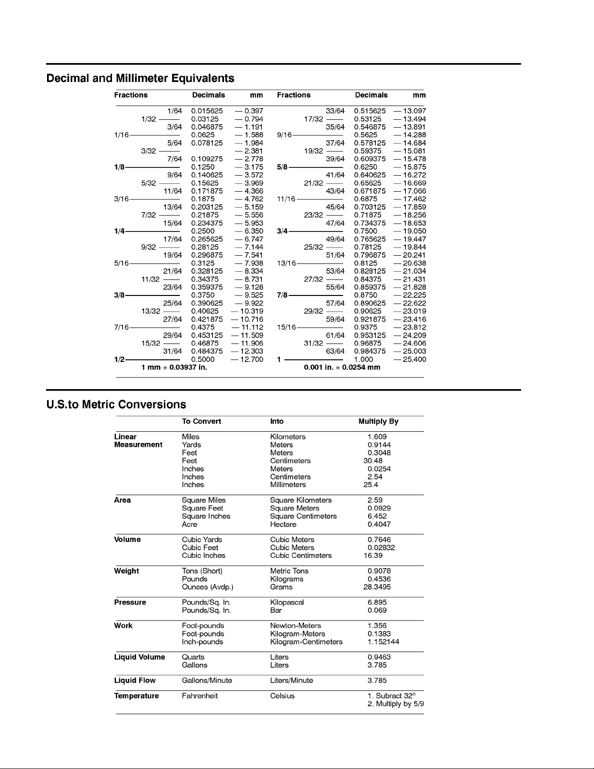
Equivalents and Conversions
0.09375
Reelmaster 3550−DPage 2 − 2Product Records and Maintenance
Page 13
Torque Specifications
Recommended fastener torque values are listed in the
following tables. For critical applications, as determined
by Toro, either the recommended torque or a torque that
is unique to the application is clearly identified and specified in this Service Manual.
These Torque Specifications for the installation and
tightening of fasteners shall apply to all fasteners which
do not have a specific requirement identified in this Service Manual. The following factors shall be considered
when applying torque: cleanliness of the fastener, use
of a thread sealant (e.g. Loctite), degree of lubrication
on the fastener, presence of a prevailing torque feature
(e.g. Nylock nut), hardness of the surface underneath
the fastener’s head or similar condition which affects t h e
installation.
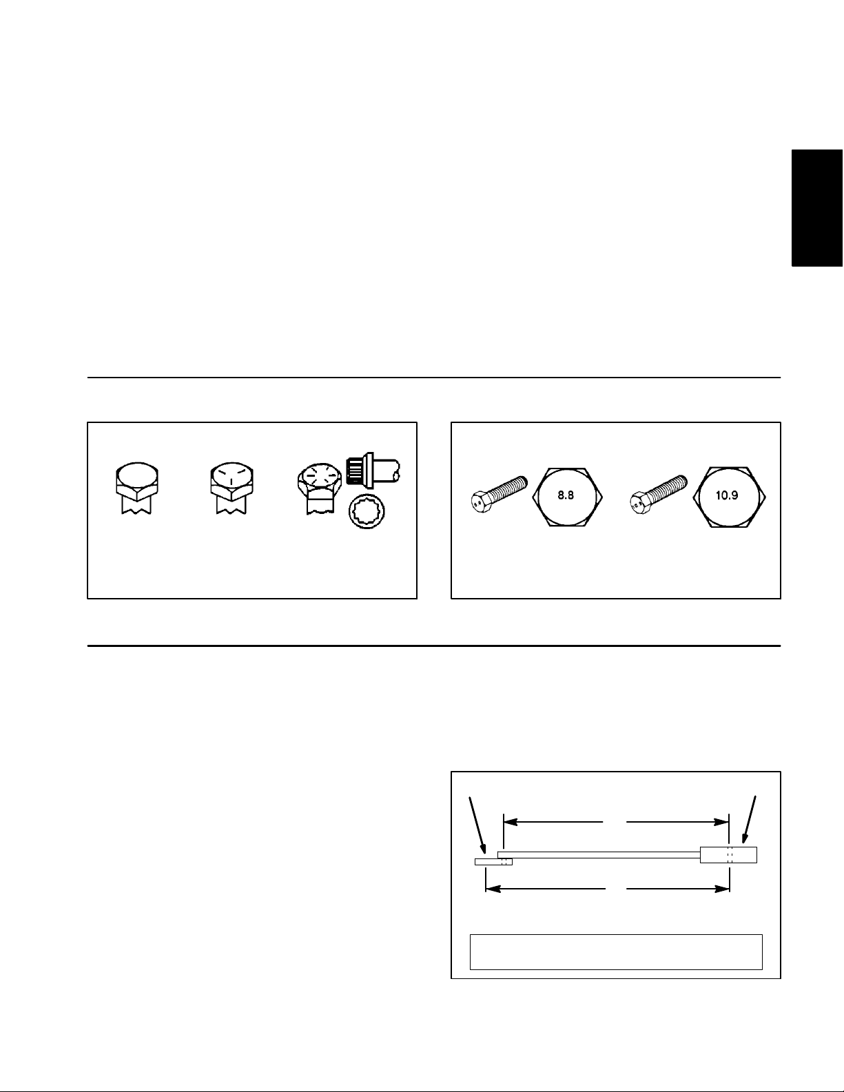
Fastener Identification
As noted in the following tables, torque values should be
reduced by 25% for lubricated fasteners to achieve
the similar stress as a dry fastener. Torque values may
also have to be reduced when the fastener is threaded
into aluminum or brass. The specific torque value
should be determined based on the aluminum or brass
material strength, fastener size, length of thread engagement, etc.
The standard method of verifying torque shall be performed by marking a line on the fastener (head or nut)
and mating part, then back off fastener 1/4 of a turn.
Measure the torque required to tighten the fastener until
the lines match up.
Product Records
and Maintenance
Grade 1 Grade 5 Grade 8
Inch Series Bolts and Screws
Figure 1
Using a Torque Wrench with an Offset Wrench
Use of an offset wrench (e.g. crowfoot wrench) will affect
torque wrench calibration due to the effective change of
torque wrench length. When using a torque wrench with
an offset wrench, multiply the listed torque recommendation by the calculated torque conversion factor (Fig.
3) to determine proper tightening torque. Tightening
torque when using a torque wrench with an offset
wrench will be lower than the listed torque recommendation.
Example: The measured effective length of the torque
wrench (distance from the center of the handle to the
center of the square drive) is 18”.
The measured effective length of the torque wrench with
the offset wrench installed (distance from the center of
the handle to the center of the offset wrench) is 19”.
Class 8.8 Class 10.9
Metric Bolts and Screws
Figure 2
If the listed torque recommendation for a fastener is
from 76 to 94 ft−lb, the proper torque when using this
torque wrench with an offset wrench would be from 72
to 89 ft−lb.
(effective length of
torque wrench)
A
B
(effective length of torque
wrench + offset wrench)
TORQUE CONVERSION FACTOR = A / B
Torque wrenchOffset wrench
The calculated torque conversion factor for this torque
wrench with this offset wrench would be 18 / 19 = 0.947.
Reelmaster 3550−D Page 2 − 3 Product Records and Maintenance
Figure 3
Page 14
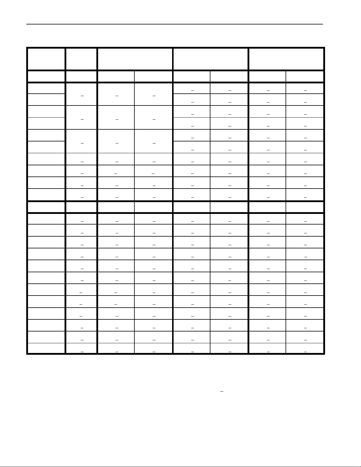
Standard Torque for Dry, Zinc Plated and Steel Fasteners (Inch Series)
Thread Size
# 6 − 32 UNC
# 6 − 40 UNF 17 + 2 192 + 23 25 + 3 282 + 34
# 8 − 32 UNC
# 8 − 36 UNF 31 + 4 350 + 45 43 + 5 486 + 56
# 10 − 24 UNC
# 10 − 32 UNF 48 + 5 542 + 56 68 + 7 768 + 79
1/4 − 20 UNC 48 + 7 53 + 7 599 + 79 100 + 10 1130 + 113 140 + 15 1582 + 169
1/4 − 28 UNF 53 + 7 65 + 10 734 + 113 115 + 12 1299 + 136 160 + 17 1808 + 192
5/16 − 18 UNC 115 + 15 105 + 15 1186 + 169 200 + 25 2260 + 282 300 + 30 3390 + 339
5/16 − 24 UNF 138 + 17 128 + 17 1446 + 192 225 + 25 2542 + 282 325 + 33 3672 + 373
3/8 − 16 UNC 16 + 2 16 + 2 22 + 3 30 + 3 41 + 4 43 + 5 58 + 7
Grade 1, 5 &
8 with Thin
Height Nuts
in−lb in−lb N−cm in−lb N−cm in−lb N−cm
10 + 2 13 + 2 147 + 23
13 + 2 25 + 5 282 + 30
18 + 2 30 + 5 339 + 56
ft−lb ft−lb N−m ft−lb N−m ft−lb N−m
SAE Grade 1 Bolts, Screws, Studs &
Sems with Regular Height Nuts
(SAE J995 Grade 2 or Stronger Nuts)
SAE Grade 5 Bolts, Screws, Studs &
Sems with Regular Height Nuts
(SAE J995 Grade 2 or Stronger Nuts)
15 + 2 169 + 23 23 + 3 262 + 34
29 + 3 328 + 34 41 + 5 463 + 56
42 + 5 475 + 56 60 + 6 678 + 68
SAE Grade 8 Bolts, Screws, Studs &
Sems with Regular Height Nuts
(SAE J995 Grade 5 or Stronger Nuts)
3/8 − 24 UNF 17 + 2 18 + 2 24 + 3 35 + 4 47 + 5 50 + 6 68 + 8
7/16 − 14 UNC 27 + 3 27 + 3 37 + 4 50 + 5 68 + 7 70 + 7 95 + 9
7/16 − 20 UNF 29 + 3 29 + 3 39 + 4 55 + 6 75 + 8 77 + 8 104 + 11
1/2 − 13 UNC 30 + 3 48 + 7 65 + 9 75 + 8 102 + 11 105 + 11 142 + 15
1/2 − 20 UNF 32 + 4 53 + 7 72 + 9 85 + 9 115 + 12 120 + 12 163 + 16
5/8 − 11 UNC 65 + 10 88 + 12 119 + 16 150 + 15 203 + 20 210 + 21 285 + 28
5/8 − 18 UNF 75 + 10 95 + 15 129 + 20 170 + 18 230 + 24 240 + 24 325 + 33
3/4 − 10 UNC 93 + 12 140 + 20 190 + 27 265 + 27 359 + 37 375 + 38 508 + 52
3/4 − 16 UNF 115 + 15 165 + 25 224 + 34 300 + 30 407 + 41 420 + 43 569 + 58
7/8 − 9 UNC 140 + 20 225 + 25 305 + 34 430 + 45 583 + 61 600 + 60 813 + 81
7/8 − 14 UNF 155 + 25 260 + 30 353 + 41 475 + 48 644 + 65 667 + 66 904 + 89
NOTE: Reduce torque values listed in the table above
by 25% for lubricated fasteners. Lubricated fasteners
are defined as threads coated with a lubricant such as
engine oil or thread sealant such as Loctite.
NOTE: The nominal torque values listed above for
Grade 5 and 8 fasteners are based on 75% of the minimum proof load specified in SAE J429. The tolerance is
approximately +
10% of the nominal torque value. Thin
height nuts include jam nuts.
NOTE: Torque values may have to be reduced when
installing fasteners into threaded aluminum or brass.
The specific torque value should be determined based
on the fastener size, the aluminum or base material
strength, length of thread engagement, etc.
Reelmaster 3550−DPage 2 − 4Product Records and Maintenance
Page 15
Standard Torque for Dry, Zinc Plated and Steel Fasteners (Metric Series)
Class 8.8 Bolts, Screws and Studs with
Thread Size
M5 X 0.8 57 + 6 in−lb 644 + 68 N−cm 78 + 8 in−lb 881 + 90 N−cm
M6 X 1.0 96 + 10 in−lb 1085 + 113 N−cm 133 + 14 in−lb 1503 + 158 N−cm
M8 X 1.25 19 + 2 ft−lb 26 + 3 N−m 28 + 3 ft−lb 38 + 4 N−m
M10 X 1.5 38 + 4 ft−lb 52 + 5 N−m 54 + 6 ft−lb 73 + 8 N−m
M12 X 1.75 66 + 7 ft−lb 90 + 10 N−m 93 + 10 ft−lb 126 + 14 N−m
M16 X 2.0 166 + 17 ft−lb 225 + 23 N−m 229 + 23 ft−lb 310 + 31 N−m
M20 X 2.5 325 + 33 ft−lb 440 + 45 N−m 450 + 46 ft−lb 610 + 62 N−m
NOTE: Reduce torque values listed in the table above
by 25% for lubricated fasteners. Lubricated fasteners
are defined as threads coated with a lubricant such as
engine oil or thread sealant such as Loctite.
NOTE: Torque values may have to be reduced when
installing fasteners into threaded aluminum or brass.
The specific torque value should be determined based
on the fastener size, the aluminum or base material
strength, length of thread engagement, etc.
Regular Height Nuts
(Class 8 or Stronger Nuts)
NOTE: The nominal torque values listed above are
based on 75% of the minimum proof load specified in
SAE J1199. The tolerance is approximately +
nominal torque value.
Class 10.9 Bolts, Screws and Studs with
Regular Height Nuts
(Class 10 or Stronger Nuts)
10% of the
Product Records
and Maintenance
Reelmaster 3550−D Page 2 − 5 Product Records and Maintenance
Page 16
Other Torque Specifications
SAE Grade 8 Steel Set Screws
Recommended Torque
Thread Size
Square Head Hex Socket
1/4 − 20 UNC 140 + 20 in−lb 73 + 12 in−lb
5/16 − 18 UNC 215 + 35 in−lb 145 + 20 in−lb
3/8 − 16 UNC 35 + 10 ft−lb 18 + 3 ft−lb
1/2 − 13 UNC 75 + 15 ft−lb 50 + 10 ft−lb
Thread Cutting Screws
(Zinc Plated Steel)
Type 1, Type 23 or Type F
Thread Size Baseline Torque*
No. 6 − 32 UNC 20 + 5 in−lb
Wheel Bolts and Lug Nuts
Thread Size
7/16 − 20 UNF
Grade 5
1/2 − 20 UNF
Grade 5
M12 X 1.25
Class 8.8
M12 X 1.5
Class 8.8
** For steel wheels and non−lubricated fasteners.
Thread Cutting Screws
(Zinc Plated Steel)
Thread
Size
No. 6 18 20 20 + 5 in−lb
Threads per Inch
Type A Type B
Recommended Torque**
65 + 10 ft−lb 88 + 14 N−m
80 + 10 ft−lb 108 + 14 N−m
80 + 10 ft−lb 108 + 14 N−m
80 + 10 ft−lb 108 + 14 N−m
Baseline Torque*
No. 8 − 32 UNC 30 + 5 in−lb
No. 10 − 24 UNC 38 + 7 in−lb
1/4 − 20 UNC 85 + 15 in−lb
5/16 − 18 UNC 110 + 20 in−lb
3/8 − 16 UNC 200 + 100 in−lb
Conversion Factors
in−lb X 11.2985 = N−cm N−cm X 0.08851 = in−lb
ft−lb X 1.3558 = N−m N−m X 0.7376 = ft−lb
No. 8 15 18 30 + 5 in−lb
No. 10 12 16 38 + 7 in−lb
No. 12 11 14 85 + 15 in−lb
* Hole size, material strength, material thickness and finish must be considered when determining specific
torque values. All torque values are based on non−lubricated fasteners.
Reelmaster 3550−DPage 2 − 6Product Records and Maintenance
Page 17

Table of Contents
SPECIFICATIONS 3............................
GENERAL INFORMATION 4.....................
Operator’s Manual 4..........................
Kubota Workshop Manual 4....................
Kubota Diesel Engine 4........................
SERVICE and REPAIRS 6.......................
Air Cleaner and Muffler 6......................
Fuel System 8................................
Radiator and Oil Cooler Assembly 10............
Engine 12....................................
KUBOTA WORKSHOP MANUAL, DIESEL ENGINE,
05 SERIES
Chapter 3
Kubota Diesel Engine
Kubota
Diesel Engine
Reelmaster 3550- D Page 3 - 1 Kubota Diesel Engine
Page 18

This page is intentionally blank.
Reelmaster 3550−DPage 3 − 2Kubota Diesel Engine
Page 19

Specifications
Item Description
Make / Designation Kubota D1105- E3B or D1105- E4B
4- Cycle, 3 Cylinder, Liquid Cooled, Diesel Engine
Bore x Stroke 3.07” x 3.09” (78 mm x 78.4 mm)
Total Displacement 68.5 in3(1123 cc)
Firing Order 1 (fan end) - 2 - 3 (flywheel end)
Direction of Rotation Counterclockwise (viewed from flywheel)
Fuel Diesel or Biodiesel (up to B20) Fuel with Low or Ultra Low
Sulfur Content
Fuel Capacity 7.5 U.S. gallons (28.4 liters)
Fuel Injection Pump Bosch MD Type Mini
Injection Nozzle Mini Nozzle (DNOPD)
Governor Centrifugal Mechanical
Low Idle (no load) 1400 + 50 RPM
High Idle (no load) 3220 + 50 RPM
Kubota
Diesel Engine
Engine Oil API CH- 4, CI- 4 or higher
Engine Oil Viscosity See Traction Unit Operator’s Manual
Crankcase Oil Capacity 4 U.S. Quarts (3.8 Liters) with Filter
Oil Pump Trochoid Type
Coolant Capacity 6 U.S. Quarts (5.7 Liters)
Starter 12 VDC 1.4 KW
Alternator/Regulator 12 VDC
Alternator Output 40 amp
Engine Dry Weight 205 lb. (93 kg)
Reelmaster 3550- D Page 3 - 3 Kubota Diesel Engine
Page 20
General Information
This Chapter gives information about specifications and
repair of the diesel engine used in the Reelmaster
3550- D.
General maintenance procedures are described in your
Traction Unit Operator’s Manual. Information on engine
troubleshooting, testing, disassembly and assembly is
identified in the Kubota Workshop Manual: 05 Series
Diesel Engine.
Most repairs and adjustments require tools which are
commonly available in many service shops. Special
Operator’s Manual
The Traction Unit Operator’s Manual provides information regarding the operation, general maintenance and
maintenance intervals for the Kubota diesel engine that
powers your Reelmaster 3550- D. Refer to this publication for additional information when servicing the machine.
Kubota Workshop Manual
tools are described in the Kubota Workshop Manual: 05
Series Diesel Engine. The use of some specialized test
equipment is explained. However, the cost of the test
equipment and the specialized nature of some repairs
may dictate that the work be done at an engine repair facility.
Service and repair parts for the Kubota engine in your
Reelmaster are available from your Authorized Toro
Distributor. If no parts list is available, be prepared to
provide your distributor with the Toro model and serial
number.
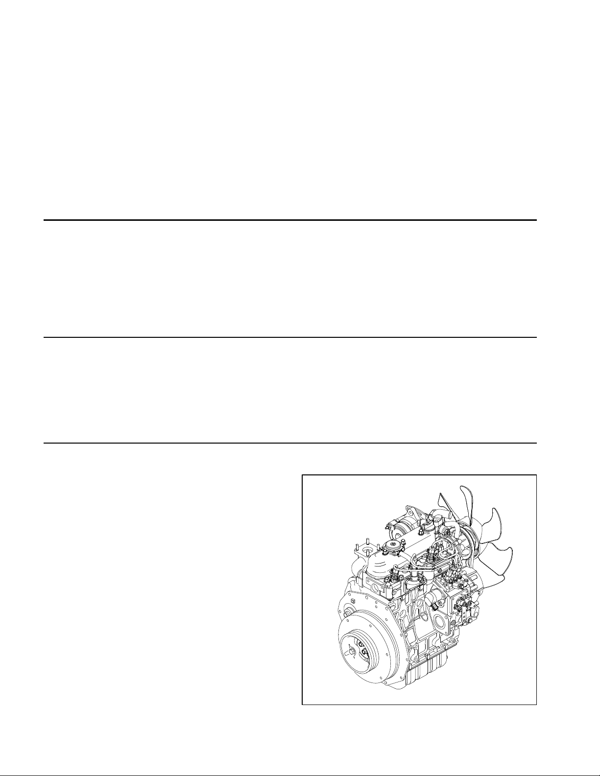
The engine that powers your Reelmaster machine is a
Kubota model D1105. The Kubota Workshop Manual is
available for these engines. Make sure that the correct
engine manual is used when servicing the engine on
your Reelmaster 3550- D.
Kubota Diesel Engine
The Kubota D1105 engine used in your Reelmaster
3550- D is a naturally aspirated engine that complies
with either EPA emission regulations Tier 4i (model
D1105- E3B) or Tier 4 (model D1105- E4B) depending
on manufacture date. The engine includes a Bosch inline injection pump.
Figure 1
Reelmaster 3550- DPage 3 - 4Kubota Diesel Engine
Page 21

This page is intentionally left blank.
Kubota
Diesel Engine
Reelmaster 3550−D Page 3 − 5 Kubota Diesel Engine
Page 22
Service and Repairs
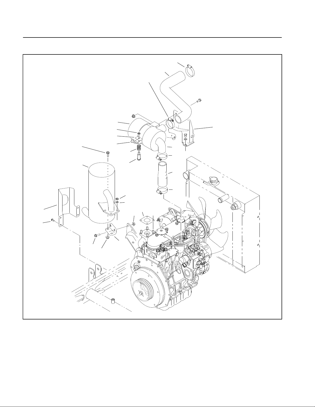
Air Cleaner and Muffler
10
11
12
14
19
21
16
4
3
15
18
17
13
12
20
12
7
8
1
9
5
2
6
4
5
1. Exhaust guard
2. Cap screw
3. Muffler
4. Flange head screw
5. Flange nut
6. Muffler bracket
7. Hex nut
Figure 2
8. Lock washer
9. Exhaust gasket
10. Hose clamp
11. Air inlet hose (upper)
12. Hose clamp
13. Air cleaner body
14. Filter cover
15. Burp (Actuator) valve
16. Mounting band assembly
17. Shoulder bolt
18. Compression spring
19. Lock nut
20. Air inlet hose (lower)
21. Air filter mount
Reelmaster 3550−DPage 3 − 6Kubota Diesel Engine
Page 23
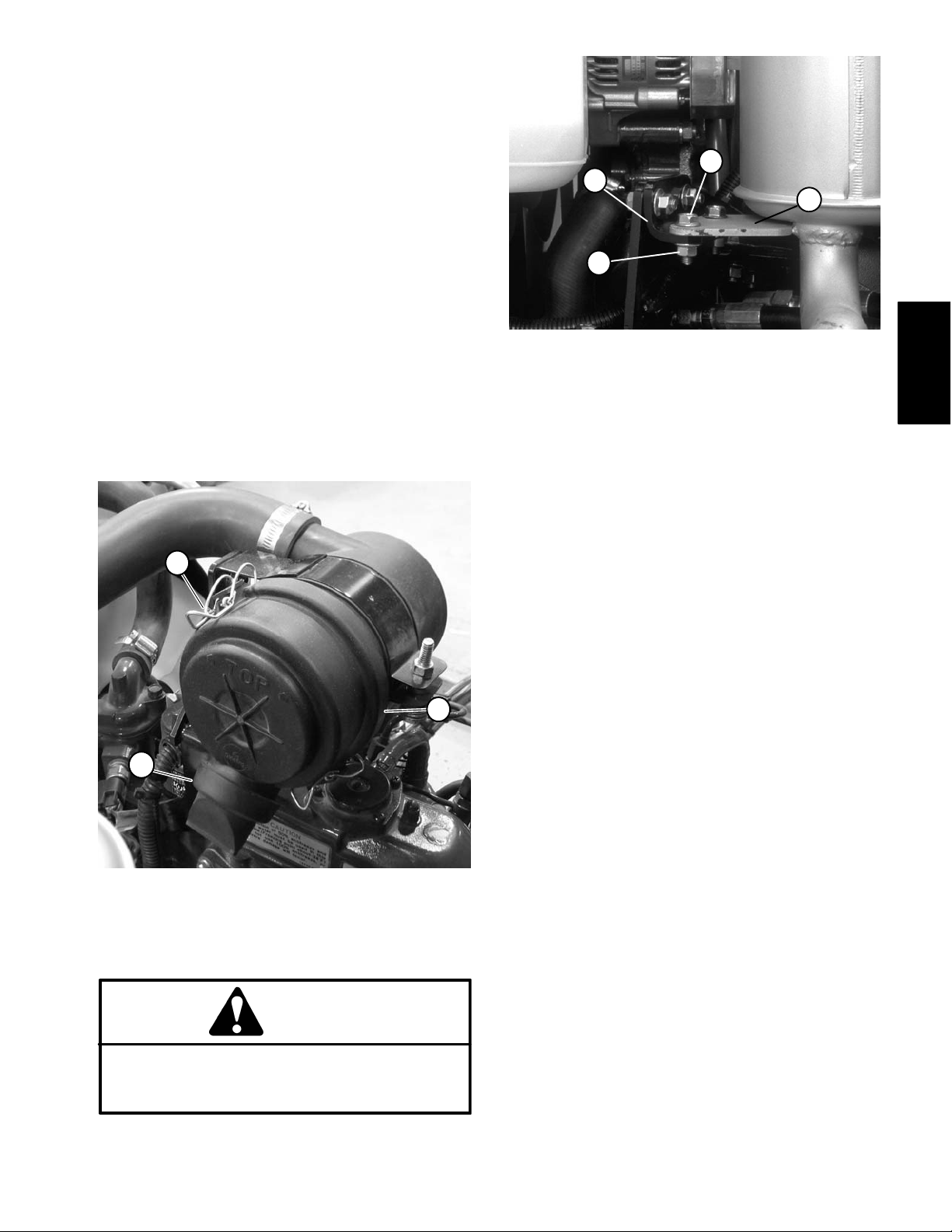
Check Air Filter, Dust Cup, & Burp Valve
The air cleaner body , air filter, dust cup, and burp valve
should be checked daily, prior to operation.
IMPORTANT: Any leaks in the air cleaner system
will cause serious engine damage. Make sure that
all air cleaner components are in good condition
and are properly secured during operation.
1. Park machine on a level surface, lower cutting units,
stop engine, engage parking brake, and remove key
from the ignition switch. Unlatch and raise hood.
2. Check air cleaner body for damage that could cause
possible air leaks. Make sure dust cup seals completely
to the air cleaner body (Fig. 3).
3. Check burp valve and dust cup for damage.
4. Make sure air hoses connecting the air cleaner to the
engine and radiator are secured tightly and free of possible air leaks.
1
2
4
3
1
Figure 4
1. Flange head nut
2. Flange head screw
3. Muffler plate
4. Muffler bracket
1. Park machine on a level surface, lower cutting units,
stop engine, engage parking brake, and remove key
from the ignition switch.
2. Open engine hood to gain access to engine.
3. Remove exhaust guard.
4. Remove both flange head nuts and screws securing
the muffler plate to the muffler bracket (Fig. 4).
Kubota
Diesel Engine
3
Figure 3
1. Latch
2. Dust cup
3. Burp valve
Muffler Removal
CAUTION
The muffler and exhaust pipe may be hot. To
avoid possible burns, allow the engine and exhaust system to cool before working on the muffler.
5. Remove four hex nuts and lock washers from the exhaust manifold studs. Separate muffler flange from the
exhaust manifold. Remove muffler from the machine.
6. Remove exhaust gasket. Replace gasket if damaged or torn.
2
Muffler Installation
NOTE: Make sure muffler flange and exhaust manifold
sealing surfaces are free of debris or damage that may
prevent a tight seal.
1. Place exhaust gasket on the exhaust manifold.
IMPORTANT: Finger tighten all fasteners before securing the muffler plate to the muffler bracket so
there is no preload on the exhaust manifold.
2. Position muffler flange to the exhaust manifold with
four lock washers and hex nuts.
3. Position mu ffler plate to the muffler bracket with both
flange head screws and nuts (Fig. 4).
4. Tighten muffler flange hex nuts and then muffler
plate screws and nuts.
5. Install exhaust guard.
6. Close and latch engine hood.
Reelmaster 3550−D Page 3 − 7 Kubota Diesel Engine
Page 24
Fuel System
6
5
4
TO
PUMP
6
12
7
10
8
11
9
3
8
13
14
2
16
15
17
18
19
20
Thread
Sealant
(typical)
11
21
22
11
38
11
33
34
29
27
28
27
1
30
31
32
Thread
Sealant
(typical)
RIGHT
TO
TANK
39
35
37
36
23
24
25
26
11
7
40
FRONT
16
41
1. Fuel tank
2. Grommet
3. Fuel gauge
4. Seat support strap (2)
5. Heat shield
6. Washer head screw (4)
7. Fuel hose (tank to pump)
8. Bushing (2)
9. Elbow fitting
10. Stand pipe
11. Hose clamp (7)
12. Fuel hose (tee to tank)
13. Cap screw (2)
14. Fuel hose strap
Figure 5
15. Fuel cap
16. Hose clamp (2)
17. Flange nut (2)
18. R−Clamp
19. Fuel hose (filter to engine)
20. Grommet
21. Barbed fitting
22. Fuel hose (pump to filter)
23. Clamp
24. Washer head screw
25. Washer head screw
26. Fuel pump
27. Hose clamp (2)
28. Fuel hose (engine return to tee)
29. Barbed fitting
30. Barbed fitting
31. Tee fitting
32. Barbed fitting
33. Elbow fitting
34. Fuel/water separator element
35. Pump mount plate
36. Cap screw (3)
37. Fuel/water separator head
38. Flange head screw (2)
39. Tank support
40. Flange head screw (2)
41. Fuel hose (tee to vent tube)
Reelmaster 3550−DPage 3 − 8Kubota Diesel Engine
Page 25
DANGER
3
Because diesel fuel is flammable, use caution
when storing or handling it. Do not smoke while
filling the fuel tank. Do not fill fuel tank while engine is running, hot or when machine is in an enclosed area. Always fill fuel tank outside and
wipe up any s p i l l e d diesel fuel before starting the
engine. Store fuel in a clean, safety−approved
container and keep cap in place. Use diesel fuel
for the engine only; not for any other purpose.
Fuel Tank Removal (Fig. 5)
1. Park machine on a level surface, lower cutting units,
stop engine, engage parking brake, and remove key
from the ignition switch. Unlatch and raise hood.
IMPORTANT: Follow all local codes and regulations
when recycling or disposing waste fuel.
2. Drain fuel from the tank into a suitable container. If
necessary.
3. Disconnect seat switch from the electrical harness.
Remove seat and seat support straps from the frame.
4. Remove fuel hose strap and both fuel hoses from the
fuel tank (Fig 6). Remove fuel tank from the machine.
Clean Fuel Tank
4
5
1
2
Figure 6
1. Seat support strap
2. Hex flange head screw
3. Electrical harness
4. Fuel hose strap
5. Fuel hose
4. Connect wire harness connector to the seat switch.
Route seat switch wire under seat support strap. Secure
seat support straps and seat to the frame (see Operator
Seat in Chapter 6 − Chassis in this manual).
5. Check that fuel tank support contacts the bottom of
the fuel tank but does not raise tank from machine
frame. Adjust location of support if necessary.
6. Check for correct seat operation. Also check that
seat switch wires and connector are not pinched and do
not contact any moving parts.
7. Fill fuel tank.
Kubota
Diesel Engine
Clean the fuel tank every 2 years. Also, clean the fuel
tank if the fuel system becomes contaminated or if the
machine is to be stored for an extended period.
1. Remove fuel tank from the machine (see Fuel Tank
Removal).
2. Flush fuel tank out with clean diesel fuel. Make sure
tank is free of contaminates and debris.
3. Install fuel tank to the machine (see Fuel Tank Installation).
Fuel Tank Installation (Fig. 5)
1. Position fuel tank to the machine.
2. Connect both fuel hoses to the tank and secure with
hose clamps.
3. Install fuel hose strap to top of tank making sure that
fuel lines are properly positioned in grooves in tank.
Reelmaster 3550−D Page 3 − 9 Kubota Diesel Engine
Page 26
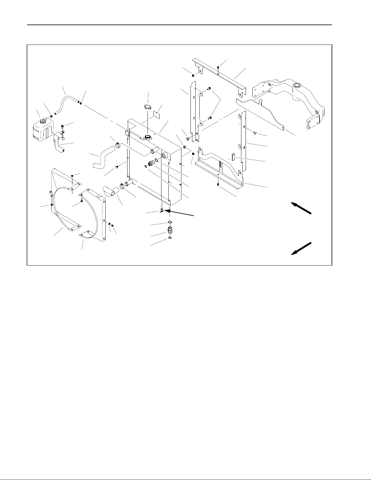
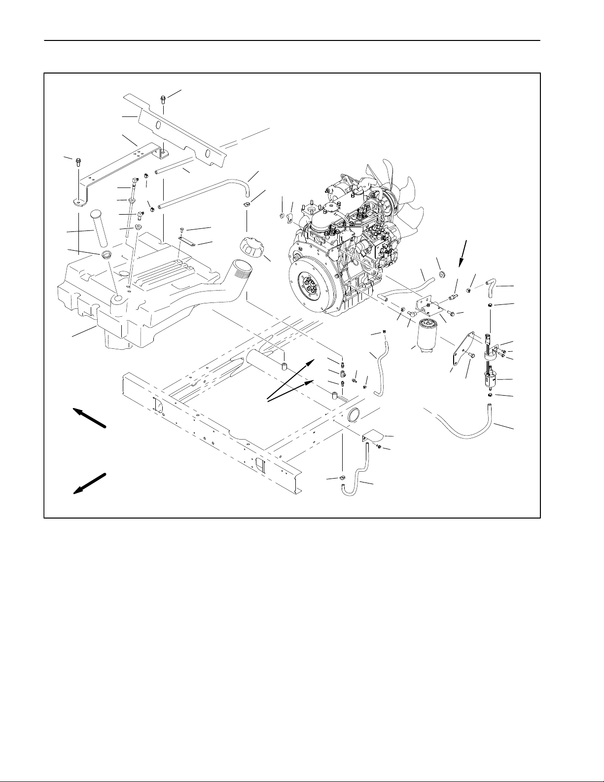
Radiator and Oil Cooler Assembly
21
2
27
19
21
18
9
20
9
10
22
25
10
5
8
16
11
14
3
4
12
24
13
21
33
23
34
Thread
Sealant
26
2
RIGHT
30
29
28
15
16
1
33
31
7
2
17
FRONT
32
6
1. Draincock valve
2. Flange head screw (8)
3. Flange nut (4)
4. Carriage bolt (4)
5. Radiator/oil cooler assembly
6. LH fan shroud
7. RH fan shroud
8. Flange head screw (4)
9. Hose clamp (2)
10. Flange head screw (6)
11. Overflow bottle bracket
12. Radiator lower shield
Figure 7
13. Magnet
14. Radiator hose (upper)
15. Radiator hose (lower)
16. Hose clamp (2)
17. Straight hydraulic fitting
18. Hose
19. Coolant expansion tank
20. Radiator cap
21. Flange nut (6)
22. Foam seal (2)
23. Adapter
24. LH radiator bracket
25. RH radiator bracket
26. Bottom radiator bracket
27. Top radiator bracket
28. Plastic plug (2)
29. Flange nut (4)
30. Flange head screw (4)
31. Flat washer (4)
32. O−ring
33. O−ring
34. O−ring
Reelmaster 3550−DPage 3 − 10Kubota Diesel Engine
Page 27
Removal (Fig. 7)
Installation (Fig. 7)
1. Park machine on a level surface, lower cutting units,
stop engine, engage parking brake and remove key
from the ignition switch.
2. Open and remove hood from the machine.
CAUTION
Do not open radiator cap or drain coolant if the
radiator or engine is hot. Pressurized, hot coolant can escape and cause burns.
Ethylene- glycol antifreeze is poisonous. Dispose of coolant properly or store it in a properly
labeled container away from children and pets.
IMPORTANT: Follow all local codes and regulations
when recycling or disposing engine coolant.
3. Drain radiator into a suitable container either by using the draincock near the lower left side corner of the
radiator or by removing the lower radiator hose from the
radiator.
4. Disconnect radiator hoses from the radiator.
1. Inspect seals around radiator location for wear or
damage. Replace seals if necessary.
2. If hydraulic fittings were removed from oil cooler, lubricate and place new O- rings onto fittings. Install fittings into port openings and tighten fittings (see
Hydraulic Fitting Installation in the General Information
section of Chapter 4 - Hydraulic System in this manual).
3. If draincock valve was removed from radiator, apply
thread sealant to draincock threads before installing it
into radiator.
4. Remove all plugs placed in radiator and hose openings during the removal procedure.
5. Carefully position radiator to the radiator brackets.
6. Secure radiator to the side radiator brackets with four
(4) carriage bolts and flange nuts. Secure top and bottom of radiator to brackets with flange head screws.
7. Connect hydraulic lines to fittings in oil cooler ports
(see Hydraulic Hose and Tube Installation in the General Information section of Chapter 4 - Hydraulic System
in this manual).
Kubota
Diesel Engine
5. Remove air cleaner inlet hose from radiator opening.
6. Read the General Precautions for Removing and
Installing Hydraulic System Components in the Service
and Repairs section of Chapter 4 - Hydraulic System in
this manual.
7. Thoroughly clean hydraulic lines at oil cooler ports.
Disconnect hydraulic lines and put caps or plugs on lines
to prevent contamination. Label disconnected hydraulic
lines for proper installation.
8. Remove coolant expansion tank and bracket from
machine.
9. Remove fan shrouds from machine.
10.Remove fasteners that secure radiator to the upper,
lower and side radiator brackets.
1 1 .Carefully separate radiator/oil cooler assembly from
brackets and remove from the machine.
12.If necessary, remove hydraulic fittings from oil cooler
and discard O- rings.
8. Position fan shrouds to radiator and secure with removed fasteners.
9. Secure coolant expansion tank and bracket to machine.
10.Connect radiator hoses to the radiator and secure
with hose clamps.
11. Install and secure air cleaner inlet hose.
12.Make sure radiator draincock valve is closed. Fill radiator with coolant.
13.Install hood to the machine. Close and latch hood.
14.Fill the hydraulic fluid tank.
15.Start the unit and run engine to normal operating
temperature. Use all of the hydraulic controls while the
engine is running to d istribute the hydraulic fluid
throughout the system.
16.Stop the engine and check the hydraulic fluid and
coolant levels. Adjust as necessary.
13.Plug all r adiator and hose openings to prevent contamination.
Reelmaster 3550- D Page 3 - 11 Kubota Diesel Engine
Page 28
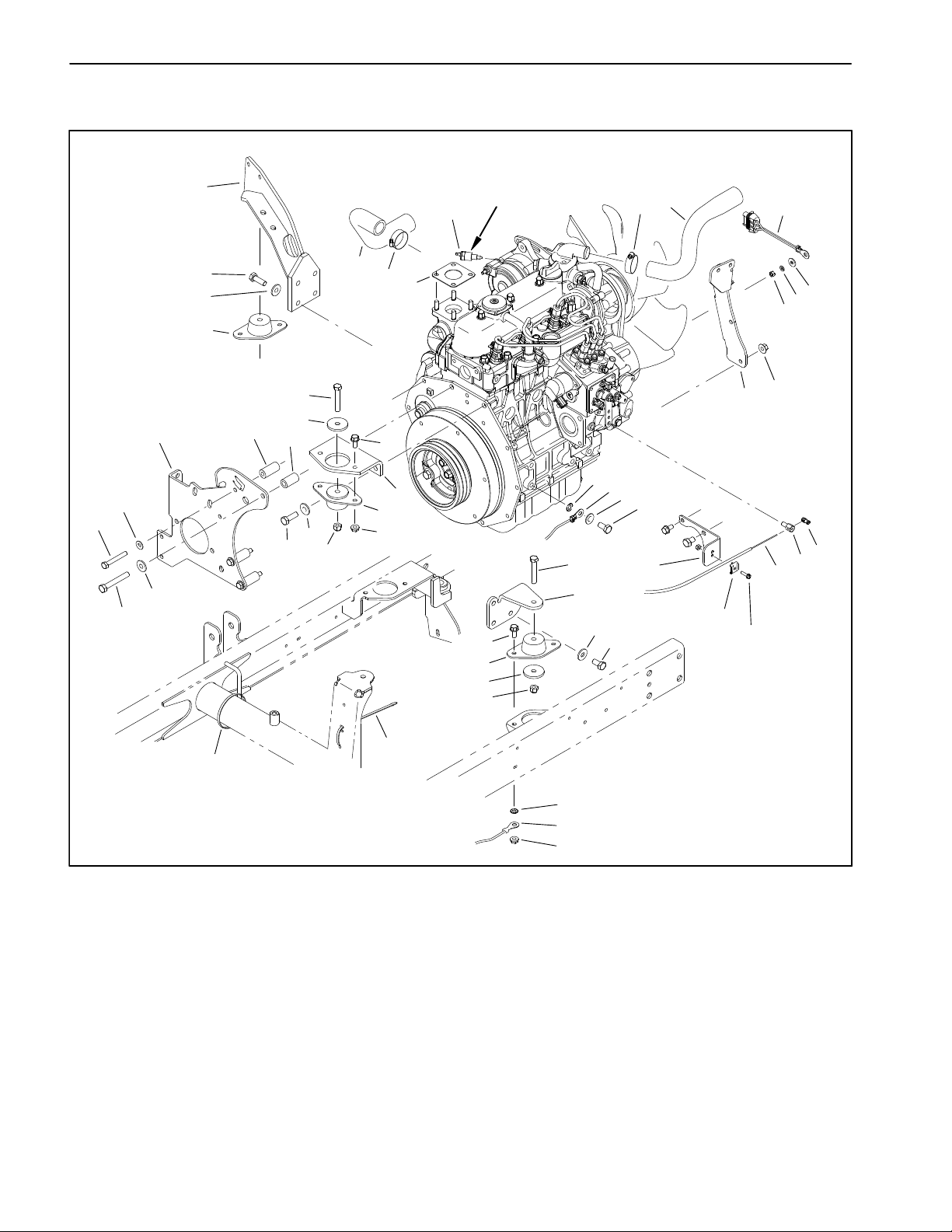
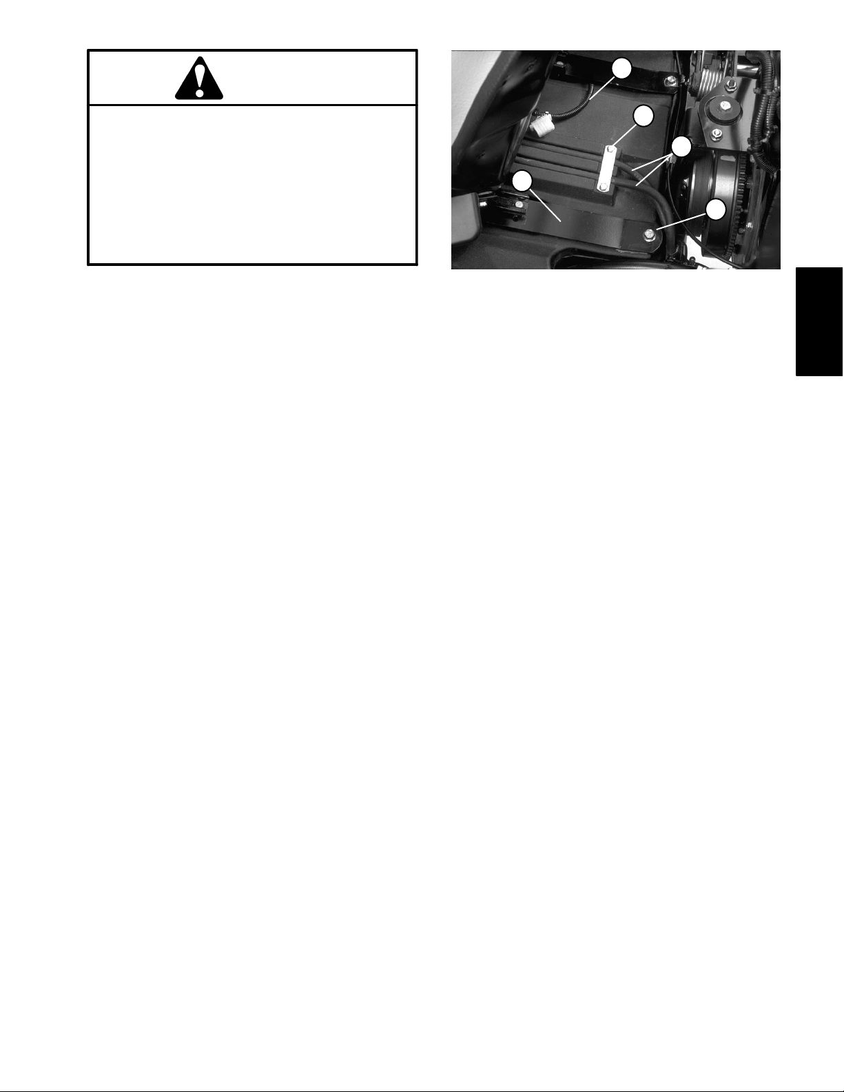
Engine
44
43
45
42
46
1
2
3
5
6
7
8
Thread Sealant
9
6
10
13
12
11
4
26
15
14
31
41
38
40
37
32
30
36
34
35
26
16
17
18
19
20
23
24
25
27
21
22
30
28
29
4
31
32
39
1. Engine mount bracket − RH
2. Cap screw
3. Hardened washer
4. Engine mount
5. Lower radiator hose
6. Hose clamp
7. Exhaust flange gasket
8. Coolant temperature switch
9. Upper radiator hose
10. Wire Harness − fusible link
11. Flat washer
12. Lock washer
13. Hex nut
14. Flange nut
15. Fuel filter bracket
16. External tooth lock washer
39
Figure 8
17. Engine ground wire
18. Flat washer
19. Cap screw
20. Throttle cable bracket
21. Cable clamp
22. Cap screw
23. Throttle cable
24. Swivel clamp
25. Cable stop
26. Cap screw
27. Engine mount bracket − LH
28. Hardened washer
29. Cap screw
30. Flange head screw
31. Hardened washer
32. Hex nut
33
17
34
33. Lock washer
34. Flange nut
35. Engine mount bracket − front
36. Engine mount
37. Hardened washer
38. Cap screw
39. Cable tie
40. Spacer (1)
41. Spacer (4)
42. Pump mount plate
43. Hardened washer
44. Cap screw
45. Cap screw
46. Hardened washer
Reelmaster 3550−DPage 3 − 12Kubota Diesel Engine
Page 29
Removal (Fig. 8)
1. Park machine on a level surface, lower cutting units,
stop engine, engage parking brake, and remove key
from the ignition switch.
2. Open and remove engine hood from the machine.
Slide seat all the way forward.
3. Disconnect air hose from the air cleaner and radiator.
Remove air cleaner assembly from the engine.
4. Disconnect both battery cables at the battery (see
Battery Service in Chapter 5 − Electrical System).
5. Remove muffler from the e x h a u s t manifold and muffler bracket (see Muffler Removal in this Chapter).
6. Drain radiator from the drain cock valve into a suitable container (see Radiator Removal in this Chapter).
Disconnect coolant hoses from the water pump and engine block.
7. Remove coolant expansion tank and bracket from
the top fan shroud. Remove top fan shroud from the radiator (see Radiator Removal in this Chapter).
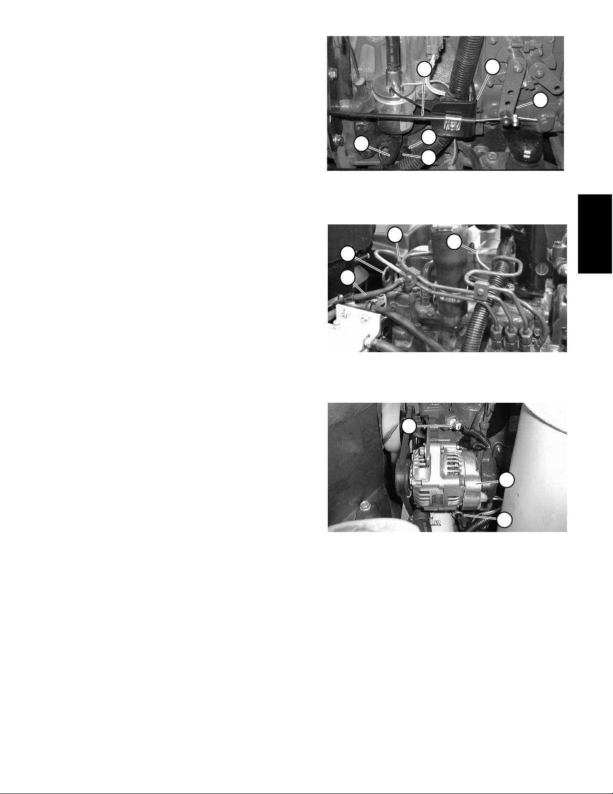
8. Disconnect wire harness and electrical wires from
the following:
A. Battery, wire harness and engine grounds
(Fig. 9).
6
1. Battery ground cable
2. Wire harness ground
3. Throttle cable
2
4
3
1. Glow plug wire
2. Rear injector nozzle
3
2
1
Figure 9
1
Figure 10
4
5
4. Support bracket
5. Speed control lever
6. Fuel hose
Kubota
Diesel Engine
3. Fuel hose
4. Lift tab
B. Glow plug bus (Fig. 10) and fuel stop solenoid.
C. Engine temperature sensor, alternator, and low
oil pressure switch (Fig. 11).
9. Disconnect throttle cable from the support and swivel on the speed control lever (Fig. 9).
10.Disconnect fuel hose from the fuel pump (Fig. 9) and
front injector nozzle.
11.Remove traction control cable from the neutral arm
assembly on the piston pump. Remove all hydraulic
hoses from the piston and gear pumps (see Piston
Pump Removal in Chapter 4− Hydraulic System).
12.Remove cable ties securing the wire harness to the
front lift tab and other engine parts. Connect hoist or lift
to the front and rear lift tabs (Fig. 10).
1
1. Engine temp. sensor
2. Alternator
2
3
Figure 11
3. Oil pressure switch
Reelmaster 3550−D Page 3 − 13 Kubota Diesel Engine
Page 30
CAUTION
CAUTION
Make sure lift or hoist can support the total
weight of the engine before removing the cap
screws from the engine and engine brackets.
13.Remove hex nuts, cap screws, and washers from the
center of the three engine mounts.
RIGHT
1
FRONT
2
3
One person should operate lift or hoist while the
other person guides the engine out of the machine.
IMPORTANT: Make sure not to damage the engine,
fuel and hydraulic lines, electrical harness, or other
parts while removing the engine.
14.Remove engine slowly from the machine.
4
5
6
7
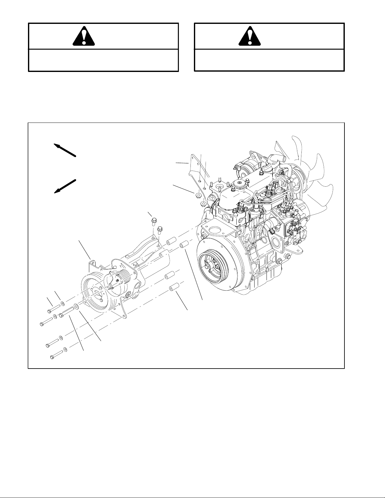
1. Engine mount bracket
2. Flange nut
3. Flange screw
4. Pump mount plate
10
9
8
Figure 12
5. Hardened washer
6. 10 mm cap screw (4)
7. 8 mm cap screw (1)
8. Hardened washer
9. Long spacer (4)
10. Short spacer (1)
Reelmaster 3550−DPage 3 − 14Kubota Diesel Engine
Page 31

15.Separate hydrostat and pump assembly from the engine as follows (Fig. 12):
A. Remove traction belt from the engine flywheel
and hydrostat pulleys.
B. Remove five cap screws, washers, and spacers
securing the pump mount plate to the engine.
tion in Chapter 4− Hydraulic System).
8. Connect fuel hose to the fuel pump (Fig. 9) and front
injector nozzle.
9. Install top fan shroud to the radiator. Install expansion tank and bracket to the top fan shroud (see Radiator
Installation in this Chapter).
C. Remove two cap screws and flange nuts securing the pump support to the engine mount bracket
and remove the hydrostat and pump assembly from
the engine.
16.As necessary, remove engine mounts, front engine
mounting bracket, throttle support bracket and left engine mounting bracket.
Installation (Fig. 8)
1. If removed, install engine mounts, front engine
mounting bracket, throttle support bracket and left engine mounting bracket. Also, make sure that all switches
and sensors are installed on engine.
2. Install hydrostat and pump assembly to the engine
as follows (Fig. 12):
A. Secure the pump support to the engine mount
bracket with two flange nuts and cap screws.
B. Secure pump mount plate to the engine with five
spacers, washers, and cap screws.
C. Install traction belt to the engine flywheel and hydrostat pulleys.
3. Connect hoist or lift to the front and rear engine lift
tabs (Fig. 10).
10.Connect wire harness and electrical wires to the following:
A. Engine grounds to the battery and wire harness
(Fig. 9).
B. Glow plug bus (Fig. 10) and fuel stop solenoid.
C. Engine temperature sensor, alternator, and low
oil pressure switch (Fig. 11).
11.Secure wire harness to engine with cable ties at lo cations noted during engine removal.
12.Connect coolant hoses to the water pump and engine block. Make sure drain cock valve is closed. Fill radiator with coolant.
13.Install muffler to the exhaust manifold and muffler
bracket (see Muffler Installation in this Chapter).
14.Connect throttle cable to the support and swivel on
the speed control lever (Fig. 9).
15.Connect both battery cables at the battery (see Battery Service in Chapter 6 − Electrical system).
16.Install air cleaner to the engine. Connect air hose to
air cleaner and radiator.
17.Adjust throttle cable.
Kubota
Diesel Engine
18.Bleed air from the fuel system.
CAUTION
19.Install engine hood to the machine. Close and latch
One person should operate lift or hoist while the
other person guides the engine into the machine.
IMPORTANT: Make sure not to damage the engine,
fuel and hydraulic lines, electrical harness, or other
parts while installing the engine.
4. Position engine slowly into the machine.
5. Secure all three engine mounts to the engine mounting brackets with cap screws, washers, and hex nuts.
6. Secure wire harness to the front lift tab and the engine with cable ties.
7. Install all hydraulic hoses to the piston and gear
pumps. Install traction control cable to the neutral arm
assembly on the piston pump (see Piston Pump Installa-
Reelmaster 3550−D Page 3 − 15 Kubota Diesel Engine
hood.
20.Fill the hydraulic fluid tank.
21.Start the unit and run engine to normal operating
temperature. Use all of the hydraulic controls while the
engine is running to distribute the hydraulic fluid
throughout the system.
22.Stop the engine and check the hydraulic fluid and
coolant levels. Adjust as necessary.
23.Adjust traction drive for neutral.
Page 32

This page is intentionally blank.
Reelmaster 3550−DPage 3 − 16Kubota Diesel Engine
Page 33

Table of Contents
Chapter 4
Hydraulic System
SPECIFICATIONS 2............................
GENERAL INFORMATION 3.....................
Operator’s Manual 3..........................
Relieving Hydraulic System Pressure 3..........
Traction Circuit Component Failure 3............
Hydraulic Hoses 4............................
Hydraulic Hose and Tube Installation 5..........
Hydraulic Fitting Installation 6..................
SPECIAL TOOLS 8.............................
HYDRAULIC SCHEMATIC 14....................
HYDRAULIC FLOW DIAGRAMS 16...............
Traction Circuit 16............................
Cutting Unit Circuit 18.........................
Lift Circuit: Lower 20..........................
Lift Circuit: Raise 22...........................
Steering Circuit 24............................
TROUBLESHOOTING 26........................
General Hydraulic System Problems 26..........
Traction Circuit Problems 27...................
Lift Circuit Problems 28........................
Steering Circuit Problems 29...................
Mow Circuit Problems 30......................
TESTING 31...................................
Traction Circuit Testing
Charge Pressure Test 34....................
Wheel Motor Efficiency Tests 36..............
Piston Pump/Hydrostat Flow and
Relief Pressure Test 40....................
Cutting Unit Circuit Testing
Pressure Test 44...........................
Reel Motor Efficiency/Case Drain Test 46......
Proportional Relief Valve (PRV)
Pressure Test 48..........................
Mow Control Manifold Relief Valve (RV)
Pressure Test 50..........................
Gear Pump (P1) Flow Test 52................
Steering/Lift Circuit Testing
Gear Pump (P2) Flow Test 54................
Relief Valve Pressure Test 58................
Steering Control Valve and
Steering Cylinder Test 60..................
ADJUSTMENTS 62.............................
Adjust Control Manifold Relief Valves 62.........
SERVICE AND REPAIRS 63.....................
General Precautions for Removing and
Installing Hydraulic System Components 63....
Check Hydraulic Lines and Hoses 64............
Priming Hydraulic Pumps 64...................
Flush Hydraulic System 65.....................
Filtering Closed- Loop Traction Circuit 66........
Charge Hydraulic System 67...................
Hydraulic Tank 68.............................
Radiator and Oil Cooler Assembly 70............
Hydraulic Pump Assembly 72..................
Piston Pump/Hydrostat 76.
Piston Pump/Hydrostat Service 80..............
Gear Pump 83................................
Gear Pump Service 86........................
Front Wheel Motors 88........................
Rear Wheel Motor 90..........................
Wheel Motor Service 92.......................
Cutting Unit Reel Motor 94.....................
Cutting Unit Reel Motor Service 96..............
Mow Control Manifold 100.....................
Mow Control Manifold Service 102..............
Lift Control Manifold 106.......................
Lift Control Manifold Service 108................
Control Manifold Cartridge Valve Service 110.....
Steering Control Valve 112.....................
Steering Control Valve Service 114..............
Steering Cylinder 116.........................
Steering Cylinder Service 118..................
Front Lift Cylinders 120........................
Rear Lift Cylinders 122........................
Lift Cylinder Service 124.......................
EATON MEDIUM DUTY PISTON PUMP REPAIR IN-
FORMATION MODEL 70160 VARIABLE DISPLACEMENT PISTON PUMP
PARKER TORQMOTORt TC, TB, TE, TJ, TF, TG,
TH and TL SERIES SERVICE PROCEDURE
SAUER/DANFOSS STEERING UNIT TYPE OSPM
SERVICE MANUAL
....................
System
Hydraulic
Reelmaster 3550- D Hydraulic SystemPage 4 - 1
Page 34

Specifications
Item Description
Piston Pump (Hydrostat) Variable displacement piston pump
Charge Pressure Specification:100 to 150 PSI (6.9 to 10.3 bar)
Maximum Displacement 1.44 in
Traction Circuit Relief Pressure (Forward Only) 3500 PSI (241 bar)
Tested: 150 to 200 PSI (10.3 to 13.8 bar)
3
/rev (23.6 cc/rev)
Tandem Gear Pump 2 section positive displacement gear type pump
Maximum Displacement Section 1 (P1 − mow) 0.58 in
Maximum Displacement Section 2 (P2 − steering & lift) 0.33 in
Wheel Motors (see note) Orbital geroller motor
Front Wheel Motor Displacement 12.0 in
Rear Wheel Motor Displacement 24.7 in
Mow Circuit Relief Pressures
Front Cutting Units (PRV) 3000 PSI (207 bar)
Rear Cutting Units (RV) 1500 PSI (103 bar)
Lift Circuit Relief Pressure (RV1) Lower: 500 PSI (34.5 bar)
Cutting Unit Motors Gear motor
Displacement 0.73 in
Steering Control Valve Distributor valve with rotary meter
Displacement 6.1 in
Relief Valve Pressure 1000 PSI (69 bar)
Hydraulic Filters 10 Micron, spin−on cartridge type
In−line Suction Strainer 100 mesh (in tank)
Hydraulic Tank Capacity 6 U.S. Gallons (22.6 Liters)
Hydraulic Fluid See Traction Unit Operator’s Manual
3
/rev (9.45 cc/rev)
3
/rev (5.34 cc/rev)
3
/rev (195 cc/rev)
3
(405 cc)
Raise: 1000 PSI (69 bar)
3
/rev (11.96 cc/rev)
3
/rev (100 cc/rev)
NOTE: The three wheel motors are similar in construction with only minor differences. The right front wheel motor and rear wheel motor have a
reverse timed manifold, and the front left wheel motor does not. The end cover of the rear motor has a check valve consisting of a ball and spring,
and both front motors lack this feature.
Reelmaster 3550−DHydraulic System Page 4 − 2
Page 35

General Information
Operator’s Manual
The Traction Unit and Cutting Unit Operator’s Manuals
provide information regarding the operation, general
maintenance and maintenance intervals for your Reelmaster machine. Refer to these publications for additional information when servicing the machine.
Relieving Hydraulic System Pressure
Before disconnecting or performing any work on the hydraulic system, all pressure in the hydraulic system
must be relieved. Park machine on a level surface, lower
cutting units fully, stop engine and apply parking brake.
To relieve hydraulic pressure in traction circuit, move
traction pedal to both forward and reverse directions. To
relieve hydraulic pressure in steering circuit, rotate
steering wheel in both directions.
System pressure in mow circuit is relieved when the cutting units are disengaged (reel enable/disable switch in
DISENGAGE position).
Traction Circuit Component Failure
The traction circuit on Reelmaster 3550−D machines is
a closed loop system that includes the piston (traction)
pump, two (2) front wheel motors and the rear wheel motor. If a component in the traction circuit should fail, debris and contamination from the failed component will
circulate throughout the traction circuit. This contamination can damage other components in the circuit so it
must be removed to prevent additional component failure.
The recommended method of removing traction circuit
contamination would be to temporarily install the Toro
high flow hydraulic filter (see Special Tools in this chapter) into the circuit. This filter should be used when connecting hydraulic test gauges in order to test traction
circuit components or after replacing a failed traction circuit component (e.g. traction (piston) pump or wheel
motor). The filter will ensure that contaminates are removed from the closed loop and thus, do not cause additional component damage.
Once the Toro high flow hydraulic filter kit has been
placed in the c i r c ui t , r a i s e a n d s u p port the machine with
To relieve hydraulic pressure in lift circuit, fully lower the
cutting units to the ground. Turn ignition switch to OFF.
NOTE: Moving steering wheel with engine off may unseat implement relief valve. If steering or lift circuits appear weak or inoperative after machine is returned to
service, repeat relieving hydraulic system pressure procedure.
all drive wheels off the ground. Then, operate the traction circuit to allow oil flow throughout the circuit. The filter will remove contamination from the traction circuit
during operation. Because the Toro high flow filter is bi−
directional, the traction circuit can be operated in both
the forward and reverse direction. The filter should be
removed from the machine after contamination has
been removed from the traction circuit. See Filtering
Closed−Loop T raction Circuit in the Service and Repairs
section of this chapter for additional information on using the Toro high flow hydraulic filter.
The alternative to using the Toro high flow hydraulic filter
kit after a traction circuit component failure would be to
disassemble, drain and thoroughly clean all components, tubes and hoses in the traction circuit. If any debris remains in the traction circuit and the machine is
operated, the debris can cause additional circuit component failure.
NOTE: If traction circuit contamination exists, the traction pump case drain could allow contaminates to enter
other hydraulic circuits on the machine.
System
Hydraulic
Reelmaster 3550−D Hydraulic SystemPage 4 − 3
Page 36

Hydraulic Hoses
r
r
-
r
Hydraulic hoses are subject to extreme conditions such
as pressure differentials during operation and exposure
to weather, sun, chemicals, very warm storage conditions or mishandling during operation and maintenance.
These conditions can cause hose damage and deterioration. Some hoses are more susceptible to these
conditions than others. Inspect all machine hydraulic
hoses frequently for signs of deterioration or damage:
WARNING
Before disconnecting or performing any work on
hydraulic system, relieve all pressure in system
(see Relieving Hydraulic System Pressure in this
section of this chapter).
Hard, cracked, cut, abraded, charred, leaking or
otherwise damaged hose.
Kinked, crushed, flattened or twisted hose.
Blistered, soft, degraded or loose hose cover.
Cracked, damaged or badly corroded hose fittings.
When replacing a hydraulic hose, be sure that the hose
is straight (not twisted) before tightening the fittings.
This can be done by observing the imprint (layline) on
the hose. Use two wrenches; hold the hose straight with
one wrench and tighten the hose swivel nut onto the fitting with the other wrench (See Hydraulic Hose and
Tube Installation in this section in this chapter). If the
hose has an elbow at one end, tighten the swivel nut on
that end before tightening the nut on the straight end of
the hose.
For additional hydraulic hose information, refer to Toro
Service Training Book, Hydraulic Hose Servicing (Part
Number 94813SL).
Keep body and hands away from pin hole leaks o
nozzles that eject hydraulic fluid under high
pressure. Use paper or cardboard, not hands, to
search for leaks. Hydraulic fluid escaping unde
pressure can have sufficient force to penetrate
the skin and cause serious injury. If fluid is in
jected into the skin, it must be surgically re
moved within a few hours by a doctor familia
with this type of injury. Gangrene may result from
such an injury.
Reelmaster 3550−DHydraulic System Page 4 − 4
Page 37

Hydraulic Hose and Tube Installation (O−Ring Face Seal Fitting)
1. Make sure threads and sealing surfaces of the hose/
tube and the fitting are free of burrs, nicks, scratches or
any foreign material.
2. As a preventative measure against leakage, it is recommended that the face seal O−ring be replaced any
time the connection is opened. Make sure the O−ring is
installed and properly seated in the fitting groove. Lightly
lubricate the O−ring with clean hydraulic oil.
3. Place the hose/tube against the fitting body so that
the flat face of the hose/tube sleeve fully contacts the O−
ring in the fitting.
4. Thread the swivel nut onto the fitting by hand. While
holding the hose/tube with a wrench, use a torque
wrench to tighten the swivel nut to the recommended
installation torque (Fig. 3). This tightening process will
require the use of an offset wrench (e.g. crowfoot
wrench). Use of an offset wrench will affect torque
wrench calibration due to the effective length change of
the torque wrench. Tightening torque when using a
torque wrench with an offset wrench will be lower than
the listed installation torque (see Using a Torque
Wrench with an Offset Wrench in the Torque Specifications section of Chapter 2 − Product Records and Maintenance).
C. Use a second wrench to tighten the nut to the correct Flats From Wrench Resistance (F.F.W.R.). The
markings on the nut and fitting body will verify that the
connection has been properly tightened.
Size F.F.W.R.
4 (1/4 in. nominal hose or tubing) 1/2 to 3/4
6 (3/8 in.) 1/2 to 3/4
8 (1/2 in.) 1/2 to 3/4
10 (5/8 in.) 1/2 to 3/4
12 (3/4 in.) 1/3 to 1/2
16 (1 in.) 1/3 to 1/2
Swivel Nut
Tube or Hose
O−ring
Fitting Body
Figure 1
System
Hydraulic
5. If a torque wrench is not available or if space at the
swivel nut prevents use of a torque wrench, an alternate
method of assembly is the Flats From Wrench Resist-
Mark Nut
and Fitting
Body
Final
Position
ance (F.F.W.R.) method (Fig. 2).
A. Using a wrench, tighten the swivel nut onto the fitting until light wrench resistance is reached (approximately 30 in−lb).
B. Mark the swivel nut and fitting body. Hold the
hose/tube with a wrench to prevent it from turning.
AT WRENCH RESISTANCE
Extend Line
Figure 2
Fitting Dash Size Hose/Tube Side Thread Size Installation Torque
4 9/16 − 18 18 to 22 ft−lb (25 to 29 N−m)
6 11/16 − 16 27 to 33 ft−lb (37 to 44 N−m)
8 13/16 − 16 37 to 47 ft−lb (51 to 63 N−m)
10 1 − 14 60 to 74 ft−lb (82 to 100 N−m)
12 1 3/16 − 12 85 to 105 ft−lb (116 to 142 N−m)
16 1 7/16 − 12 110 to 136 ft−lb (150 to 184 N−m)
Initial
Position
AFTER TIGHTENING
20 1 11/16 − 12 140 to 172 ft−lb (190 to 233 N−m)
Figure 3
Reelmaster 3550−D Hydraulic SystemPage 4 − 5
Page 38

Hydraulic Fitting Installation (SAE Straight Thread O−Ring Fitting into Component Port)
Non−Adjustable Fitting (Fig. 4)
1. Make sure all threads and sealing surfaces of fitting
and component port are free of burrs, nicks, scratches
or any foreign material.
2. As a preventative measure against leakage, it is recommended that the O−ring be replaced any time the
connection is opened.
3. Lightly lubricate the O−ring with clean hydraulic oil.
Fitting threads should be clean with no lubricant applied.
IMPORTANT: Before installing fitting into port, determine port material. If fitting is to be installed into
an aluminum port, installation torque is reduced.
4. Install the fitting into the port. Then, use a torque
wrench and socket to tighten the fitting to the recommended installation torque (Fig. 5).
NOTE: Use of an offset wrench (e.g. crowfoot wrench)
will affect torque wrench calibration due to the effective
length change of the torque wrench. Tightening torque
when using a torque wrench with an offset wrench will
be less than the recommended installation torque. See
Using a Torque Wrench with an Offset Wrench in the
Torque Specifications section of Chapter 2 − Product
Records and Maintenance to determine necessary conversion information.
5. If a torque wrench is not available, or if space at the
port prevents use of a torque wrench, an alternate method of assembly is the Flats From Finger Tight (F.F.F.T.)
method.
A. Install the fitting into the port and tighten it down
full length until finger tight.
B. If port material is steel, tighten the fitting to the
listed F.F.F.T. If port material is aluminum, tighten fitting to 60% of listed F.F.F.T.
Size F.F.F.T.
4 (1/4 in. nominal hose or tubing) 1.00 +
6 (3/8 in.) 1.50 + 0.25
8 (1/2 in.) 1.50 +
10 (5/8 in.) 1.50 +
12 (3/4 in.) 1.50 +
16 (1 in.) 1.50 + 0.25
Fitting
O−ring
0.25
0.25
0.25
0.25
Figure 4
Fitting
Dash Size
Fitting Port Side
Thread Size
Installation Torque Into
Steel Port
Installation Torque Into
Aluminum Port
4 7/16 − 20 15 to 19 ft−lb (21 to 25 N−m) 9 to 11 ft−lb (13 to 15 N−m)
5 1/2 − 20 18 to 22 ft−lb (25 to 29 N−m) 11 to 15 ft−lb (15 to 20 N−m)
6 9/16 − 18 34 to 42 ft−lb (47 to 56 N−m) 20 to 26 ft−lb (28 to 35 N−m)
8 3/4 − 16 58 to 72 ft−lb (79 to 97 N−m) 35 to 43 ft−lb (48 to 58 N−m)
10 7/8 − 14 99 to 121 ft−lb (135 to 164 N−m) 60 to 74 ft−lb (82 to 100 N−m)
12 1 1/16 − 12 134 to 164 ft−lb (182 to 222 N−m) 81 to 99 ft−lb (110 to 134 N−m)
14 1 3/16 − 12 160 to 196 ft−lb (217 to 265 N−m) 96 to 118 ft−lb (131 to 160 N−m)
16 1 5/16 − 12 202 to 248 ft−lb (274 to 336 N−m) 121 to 149 ft−lb (165 to 202 N−m)
20 1 5/8 − 12 247 to 303 ft−lb (335 to 410 N−m) 149 to 183 ft−lb (202 to 248 N−m)
Figure 5
Reelmaster 3550−DHydraulic System Page 4 − 6
Page 39

Adjustable Fitting (Fig. 6)
1. Make sure all threads and sealing surfaces of fitting
and component port are free of burrs, nicks, scratches
or any foreign material.
2. As a preventative measure against leakage, it is recommended that the O−ring be replaced any time the
connection is opened.
3. Lightly lubricate the O−ring with clean hydraulic oil.
Fitting threads should be clean with no lubricant applied.
4. Turn back the lock nut as far as possible. Make sure
the back up washer is not loose and is pushed up as far
as possible (Step 1 Fig. 7).
IMPORTANT: Before installing fitting into port, determine port material. If fitting is to be installed into
an aluminum port, installation torque is reduced.
Lock Nut
Back−up Washer
O−ring
Figure 6
5. Install the fitting into the port and tighten finger tight
until the washer contacts the face of the port (Step 2).
6. T o put the fitting in the desired position, unscrew it by
the required amount, but no more than one full turn
(Step 3).
7. Hold the fitting in the desired position with a wrench
and use a torque wrench to tighten the fitting to the recommended installation torque (Fig. 5). This tightening
process will require the use of an offset wrench (e.g.
crowfoot wrench). Use of an offset wrench will affect
torque wrench calibration due to the effective length
change of the torque wrench. Tightening torque when
using a torque wrench with an offset wrench will be lower
than the listed installation torque (see Using a Torque
Wrench with an Offset Wrench in the Torque Specifications section of Chapter 2 − Product Records and Maintenance).
8. If a torque wrench is not available, or if space at the
port prevents use of a torque wrench, an alternate method of assembly is the Flats From Finger Tight (F.F.F.T.)
method. Hold the fitting in the desired position with a
wrench and, if port material is steel, tighten the lock nut
with a second wrench to the listed F.F.F.T (Step 4). If port
material is aluminum, tighten fitting to 60% of listed
F.F.F.T.
Step 3Step 1
Step 2 Step 4
Figure 7
System
Hydraulic
Size F.F.F.T.
4 (1/4 in. nominal hose or tubing) 1.00 +
6 (3/8 in.) 1.50 + 0.25
8 (1/2 in.) 1.50 +
10 (5/8 in.) 1.50 +
12 (3/4 in.) 1.50 +
16 (1 in.) 1.50 +
0.25
0.25
0.25
0.25
0.25
Reelmaster 3550−D Hydraulic SystemPage 4 − 7
Page 40

Special Tools
Order the following special tools from your Toro Distributor.
Hydraulic Pressure Test Kit
Use to take various pressure readings for diagnostic
tests. Quick disconnect fittings provided attach directly
to mating fittings on machine test ports without tools. A
high pressure hose is provided for remote readings.
Contains one each: 1000 PSI (70 Bar), 5000 PSI (350
Bar) and 10000 PSI (700 Bar) gauges. Use gauges as
recommended in Testing section of this chapter.
Toro Part Number: TOR47009
Hydraulic Tester (Pressure and Flow)
Figure 8
Use to test hydraulic circuits and components for flow
and pressure capacities as recommended in the Testing
section of this chapter. This tester includes the following:
1. INLET HOSE: Hose connected from the system circuit to the inlet side of the hydraulic tester.
2. LOAD VALVE: A simulated working load is created
in the circuit by turning the valve to restrict flow.
3. PRESSURE GAUGE: Glycerine filled 0 to 5000 PSI
gauge to provide operating circuit pressure.
4. FLOW METER: This meter measures actual oil flow
in the operating circuit with a gauge rated from 1 to 15
GPM (5 to 55 LPM).
5. OUTLET HOSE: A hose from the outlet side of the
hydraulic tester connects to the hydraulic system circuit.
6. FITTINGS: An assortment of hydraulic fittings are included with this kit.
Toro Part Number: TOR214678
Figure 9
Reelmaster 3550−DHydraulic System Page 4 − 8
Page 41

40 GPM Hydraulic Tester (Pressure and Flow)
Use to test hydraulic circuits and components for flow
and pressure capacities as recommended in the Testing
section of this chapter. This tester includes the following:
1. LOAD VALVE: A simulated working load is created
in the circuit by turning the valve to restrict flow.
2. PRESSURE GAUGE: Glycerine filled 0 to 5000 PSI
gauge to provide operating circuit pressure.
3. FLOW METER: This meter measures actual oil flow
in the operating circuit with a gauge rated from 4 to 40
GPM (20 to 150 LPM).
Toro Part Number: AT40002
NOTE: This tester does not include hydraulic hoses
(see Hydraulic Hose Kit TOR6007 below).
Hydraulic Hose Kit
This kit includes hydraulic fittings and hoses needed to
connect 40 GPM hydraulic tester (AT40002) or high flow
hydraulic filter kit (TOR6011) to machine hydraulic traction system components.
Toro Part Number: TOR6007
Figure 10
Figure 11
System
Hydraulic
Reelmaster 3550−D Hydraulic SystemPage 4 − 9
Page 42

High Flow Hydraulic Filter Kit
The high flow hydraulic filter kit is designed with large
flow (40 GPM/150 LPM) and high pressure (5000
PSI/345 bar) capabilities. This kit provides for bi−directional filtration which prevents filtered debris from being
allowed back into the circuit regardless of flow direction.
If a component failure occurs in the closed loop traction
circuit, contamination from the failed part will remain in
the circuit until removed. When connecting hydraulic
test gauges in order to test traction circuit components
or after replacing a failed traction circuit component (e.g.
piston (traction) pump or wheel motor), the high flow hydraulic filter can be installed in the traction circuit. The
filter will ensure that contaminates are removed from the
closed loop and thus, do not cause additional component damage.
Toro Part Number: TOR6011
NOTE: This kit does not include hydraulic hoses (see
Hydraulic Hose Kit TOR6007 above).
NOTE: Replacement filter element is Toro part number
TOR6012. Filter element canister tightening torque is 25
ft−lb (34 N−m).
Figure 12
Hydraulic Test Fitting Kit
This kit includes a variety of O−ring Face Seal fittings to
enable you to connect test gauges into the system.
The kit includes: tee’s, unions, reducers, plugs, caps
and male test fittings.
Toro Part Number: TOR4079
Figure 13
Reelmaster 3550−DHydraulic System Page 4 − 10
Page 43

Measuring Container
Use this container for doing hydraulic motor efficiency
testing (motors with case drain lines only). Measure efficiency of a hydraulic motor by restricting the outlet flow
from the motor and measuring leakage from the case
drain line while the motor is pressurized by the hydraulic
system.
The table in Figure 15 provides gallons per minute
(GPM) conversion for measured milliliter or ounce motor
case drain leakage.
Toro Part Number: TOR4077
Figure 14
System
Hydraulic
O−ring Kit
The kit includes O−rings in a variety of sizes for face seal
and port seal hydraulic connections. It is recommended
that O−rings be replaced whenever a hydraulic connection is loosened.
Toro Part Number: 117−2727
Figure 15
Figure 16
Reelmaster 3550−D Hydraulic SystemPage 4 − 11
Page 44

Remote Starter Switch
After flushing the hydraulic system or replacing a hydraulic component (e.g. gear pump, piston pump, wheel
motor), it is necessary to prime the hydraulic pumps. A
remote starter switch (Fig. 17) can be used for this purpose. Obtain a remote starter switch locally.
IMPORTANT: When using a remote starter switch, it
is highly recommended to include a 20 amp in−line
fuse between the battery and switch connector for
circuit protection.
A remote stater switch can also be constructed using
Toro switch #106−2027, a length of 14 gauge wire, a 20
amp in−line fuse, two (2) alligator clips and necessary
connectors. Connecting the wire to switch terminals 1
and 2 will allow the momentary switch contacts to be
used for the remote starter switch (Fig. 18).
NOTE: For information on using the remote starter
switch to prime the hydraulic pumps, see Flush Hydraulic System in the Service and Repairs section of this
chapter.
MACHINE
BATTERY
STARTER
SOLENOID
MACHINE
STARTER
Figure 17
20 AMP
FUSE
TORO SWITCH
(#106−2027)
1. Starter motor
2. Starter solenoid
Figure 18
3
1
Figure 19
3. B+ terminal
2
Reelmaster 3550−DHydraulic System Page 4 − 12
Page 45

Wheel Hub Puller
Toro Part Number: TOR4097
The wheel hub puller allows safe removal of the wheel
hub from the shaft of wheel motors.
Figure 20
System
Hydraulic
Reelmaster 3550−D Hydraulic SystemPage 4 − 13
Page 46

Hydraulic Schematic
R
.035”
.040”
.040”
.040”
6.1
S4S3
500 PSI
RV1
OR6
OR4
.046”
C2
C4
.046”
C6
OR8
0.625” Rod
2.00” Bore
3.79” Stroke
STEERING CYLINDER
Extend
0.625” Rod
2.25” Stroke
0.625” Rod
2.33” Stroke
0.625” Rod
2.33” Stroke
0.625” Rod
2.25” Stroke
Extend
To Lower
To Lower
2x
1.50” Bore
1.50” Bore
1.50” Bore
1.50” Bore
L
OR7
C5
OR5
C3 C7
OR3
C1
OR1
OR2
.046”
1000 PSI
.055”
C8
S2
ET
VALVE
CONTROL
STEERING
P
S1
4.0 GPM
T
P
G1
MANIFOLD
LIFT CONTROL
BYPASS
G2
MOW = 10 GPM (6 MPH)
TRANSPORT = 18 GPM (11 MPH)
C2
7.0 GPM
12.012.0
3200 / 1400
ENGINE IDLE
VALVE
3500 PSI
100−150 PSI
1.44
P1P2
.33 .58
24.7
ENGINE RPM
PUMP RPM = 0.96 x
200−300 PSI
G1
de−energized
All solenoids are shown as
Hydraulic Schematic
Reelmaster 3550−D
NOTE: A larger hydraulic schematic is included
in Chapter 8 − Foldout Drawings.
M3
RV
1500 PSI
MANIFOLD
MOW CONTROL
MV
.73 .73 .73 .73
REEL #1 REEL #5 REEL #2 REEL #3
.73
REEL #4
M2
M1
CV1
(SW)
SWITCH
BACKLAP
OR2
.020”
OR1
FC
LC
.050”
PRV
G
T
3000 PSI
P
OIL COOLER
25 PSI
OIL FILTER
SUCTION
STRAINER
BREATHER
Reelmaster 3550−DHydraulic System Page 4 − 14
Page 47

This page is intentionally blank.
System
Hydraulic
Reelmaster 3550−D Hydraulic SystemPage 4 − 15
Page 48

Hydraulic Flow Diagrams
R
0.625” Rod
2.00” Bore
3.79” Stroke
STEERING CYLINDER
Extend
0.625” Rod
2.25” Stroke
0.625” Rod
2.33” Stroke
0.625” Rod
2.33” Stroke
0.625” Rod
2.25” Stroke
Extend
To Lower
To Lower
2x
1.50” Bore
1.50” Bore
1.50” Bore
1.50” Bore
6.1
L
S4S3
OR7
.035”
C5
OR5
.040”
C3 C7
OR3
.040”
C1
OR1
.040”
OR2
.046”
OR6
OR4
.046”
C4
C2
500 PSI
.046”
C6
RV1
OR8
1000 PSI
.055”
C8
S2
ET
VALVE
CONTROL
STEERING
P
S1
4.0 GPM
T
P
G1
MANIFOLD
LIFT CONTROL
12.012.0
BYPASS
VALVE
G2
MOW = 10 GPM (6 MPH)
TRANSPORT = 18 GPM (11 MPH)
C2
100−150 PSI
7.0 GPM
3200 / 1400
ENGINE IDLE
PUMP RPM = 0.96 x
3500 PSI
1.44
P1P2
.33 .58
24.7
ENGINE RPM
G1
200−300 PSI
.73 .73 .73 .73
Working Pressure
Low Pressure (Charge)
Return or Suction
Flow
Traction Circuit (Forward)
Reelmaster 3550−D
.73
REEL #1 REEL #5 REEL #2 REEL #3
REEL #4
MANIFOLD
MOW CONTROL
MV
M2
M1
CV1
(SW)
SWITCH
BACKLAP
1500 PSI
.020”
OR2
OR1
FC
RV
.050”
M3
SUCTION
25 PSI
OIL FILTER
LC
PRV
G
T
OIL COOLER
3000 PSI
P
STRAINER
BREATHER
Reelmaster 3550−DHydraulic System Page 4 − 16
Page 49

Traction Circuit
The traction circuit of the hydraulic system consists of a
hydrostat connected in a closed loop circuit to three orbital geroller wheel motors.
The mow/transport slide control on Reelmaster 3550−D
machines has positions for mow and transport. The
mow position allows traction pedal inputs that are appropriate for mow speeds by limiting the movement of the
traction pedal and the piston pump swash plate. The
transport position allows full movement of the traction
pedal so complete pump swash rotation is possible.
Forward
The engine drives traction pump (P3) indirectly through
pulleys and a V−belt. The traction pump is a variable displacement piston pump/hydrostat. The traction pedal
connects through a cable to the trunnion shaft and
swash plate of the pump. With the engine running and
the traction pedal in the neutral position, traction pump
(P3) supplies no flow to the wheel motors. When the
traction pedal is pressed to the forward position, the
cable from the pedal positions the swash plate in the
traction pump so fluid flows out of the hydrostat lower
port. Fluid flow out of the lower port goes to the front
wheel motors first, turning them in the forward direction.
Fluid flowing out of the front wheel motors flows to the
rear wheel motor, turning it in a forward direction. Fluid
flowing out of the rear wheel motor returns to the upper
port of the hydrostat and is continuously pumped out of
the lower port.
Operating pressure in the closed traction circuit is determined by the amount of load developed by the wheel
motors. As the load increases, circuit pressure can increase to the relief valve setting of 3500 psi (241 bar).
In forward operation, fluid flows through the internal hydrostat relief valve to the low pressure side of the traction circuit when circuit pressure exceeds the relief
setting.
Reverse
The traction circuit operates essentially the same in reverse as it does in forward. However, there are a few differences in operation.
When the reverse traction pedal is depressed, the cable
from the pedal positions the swash plate in the traction
pump (P3) so fluid flows out of the hydrostat upper port.
Fluid flow out of the upper port goes to the rear wheel
motor where an internal check valve allows the hydraulic fluid to bypass the motor. Fluid flow out of the rear
wheel motor flows to the front wheel motors, turning
them in the reverse direction. Fluid flow out of the front
wheel motors returns to the lower port of the hydrostat
and is continuously pumped out of the upper port.
NOTE: The rear wheel motor does not help propel the
traction unit in reverse.
Charge Circuit
The traction pump uses a small amount of hydraulic fluid
for internal lubrication. Fluid is designed to leak across
internal pump parts into the case drain. This leakage results in the loss of hydraulic fluid from the closed loop circuit that must be replenished via the charge circuit.
The gear pump (P2) is directly coupled to the hydrostat
through gear pump (P1) and driven by the engine. Gear
pump (P2) supplies hydraulic pressure for operating the
power steering system, raising and lowering the cutting
units, and operating the sidewinder unit. Gear pump
(P2) may also be referred to as the charge pump as flow
from the gear pump also replenishes the closed loop
traction circuit. Hydraulic fluid exits the lift/sidewinder
valve, passes through the hydraulic manifold where it
actuates logic cartridge (LC1), and continues on to the
hydrostat. A relief valve located in the hydrostat
provides sufficient resistance so that flow is guided to
the low pressure side of the traction circuit through one
of two check valves (charge circuit). Pump flow in excess of charge circuit requirements is relieved through
the relief valve back to the gear pump inlet and hydraulic
tank.
Traction Circuit Cooling
The traction circuit is cooled by a bleed off circuit in the
piston pump. The piston pump includes an internal
bleed valve which allows a small amount of hydraulic oil
to pass from the return side of the pump while operating
the traction unit in the forward direction. The charge circuit replenishes oil that is bled from the traction circuit by
the bleed valve.
When operating the traction circuit in the reverse direction, the bleed valve closes once reverse pressure
reaches 200 to 300 PSI (13.8 to 20.6) to allow normal
reverse operation.
NOTE: The bleed valve threads into the piston pump
back plate. Access to the bleed valve requires removal
of the back plate from the piston pump.
System
Hydraulic
Reelmaster 3550−D Hydraulic SystemPage 4 − 17
Page 50

0.625” Rod
2.00” Bore
3.79” Stroke
STEERING CYLINDER
Extend
0.625” Rod
2.25” Stroke
0.625” Rod
2.33” Stroke
0.625” Rod
2.33” Stroke
0.625” Rod
2.25” Stroke
Extend
To Lower
To Lower
2x
1.50” Bore
1.50” Bore
1.50” Bore
1.50” Bore
12.012.0
24.7
ET
R
3200 / 1400
ENGINE IDLE
6.1
L
S4S3
OR7
.035”
C5
OR5
.040”
C3 C7
OR3
.040”
C1
OR1
.040”
OR2
.046”
OR6
OR4
.046”
C4
C2
500 PSI
.046”
C6
RV1
OR8
1000 PSI
.055”
C8
S2
VALVE
CONTROL
STEERING
P
S1
4.0 GPM
T
P
G1
MANIFOLD
LIFT CONTROL
G2
C2
7.0 GPM
BYPASS
VALVE
MOW = 10 GPM (6 MPH)
TRANSPORT = 18 GPM (11 MPH)
100−150 PSI
ENGINE RPM
PUMP RPM = 0.96 x
G1
3500 PSI
200−300 PSI
1.44
P1P2
.33 .58
.73 .73 .73 .73
High Pressure
Low Pressure (Charge)
Return or Suction
Flow
Cutting Unit Circuit − Mow
Reelmaster 3550−D
REEL #1 REEL #5 REEL #2 REEL #3
.73
REEL #4
MANIFOLD
MOW CONTROL
MV
M2
M1
CV1
(SW)
SWITCH
BACKLAP
1500 PSI
.020”
OR2
OR1
FC
RV
.050”
M3
SUCTION
25 PSI
OIL FILTER
OIL COOLER
LC
PRV
G
T
3000 PSI
P
STRAINER
BREATHER
Reelmaster 3550−DHydraulic System Page 4 − 18
Page 51

Cutting Unit Circuit
Mow
The tandem gear pump is directly coupled to the piston
pump/hydrostat which is belt driven by the engine. The
front section of the gear pump (P1) supplies hydraulic
flow for the cutting unit circuit. The gear pump takes its
suction from the hydraulic tank.
Proportional relief valve (PRV) in the mow control manifold is de−energized with the engine running when either the reel enable/disable switch is in the DISABLE
position, the cutting units are raised or the mow/transport slide is in the TRANSPORT position. The de−energized PRV allows gear pump flow directly to the
hydraulic tank by−passing the reel motors so the cutting
reel blades remain stationary.
Proportional relief valve (PRV) is energized by the TEC
controller with the engine running when the reel enable/
disable switch is in the ENABLE position, the cutting
units are down and the mow/transport slide is in the
MOW position. In the energized position, this valve directs gear pump oil flow toward the reel motors and also
functions as the relief valve for the front reel motors.
Maximum front reel motor pressure is 3000 PSI (207
bar). Front reel motor circuit pressure can be monitored
at the test fitting in mow control manifold port G.
When the mow circuit is engaged, oil flow from manifold
port P flows through the flow control valve (FC) used to
adjust reel speed. With the backlap valve (MV) in the
MOW position, oil flows through the backlap valve (MV),
out the manifold port (M1), and to the reel motors that
are connected in series. Any excess flow above the flow
control valve setting is by−passed to the reservoir
through the logic cartridge valve (LC). The logic cartridge valve (LC) reduces fluctuations in reel speed by
compensating for pressure variations across the flow
control valve (FC).
Mow circuit oil flows through the front reel motors and
then the rear reel motors as it turns the motors in the
mow direction. Manifold relief valve (RV) provides relief
protection for the rear reel motors at a pressure less
than the proportional relief valve (PRV). If pressure to
the rear motors reaches 1500 PSI (103 bar), relief valve
(RV) opens.
BACKLAP
SWITCH
(SW)
G
TO HYDRAULIC
TANK
.73
REEL #4
.73 .73 .73 .73
REEL #1 REEL #5 REEL #2 REEL #3
M1
M2
MV
CV1
FC
OR1
.050”
PRV
3000 PSI
P
MOW CONTROL
MANIFOLD
OR2
.020”
LC
TO OIL
COOLER
T
1500 PSI
FROM GEAR
RV
M3
PUMP
Figure 21
Backlap (Fig. 21)
Backlapping operation is the similar to mowing operation, except for the position of the backlap valve (MV).
When the backlap valve (MV) is in the BACKLAP position, oil flows through the rear reel motors and then the
front reel motors as it turns the motors in the backlap
direction.
System
Hydraulic
Oil flow from the reel motors returns into mow control
manifold port (M2), through backlap valve (MV), through
manifold check valve CV1 and exits the manifold
through pot (T). Oil returns to the hydraulic tank through
the oil cooler and oil filter.
Reelmaster 3550−D Hydraulic SystemPage 4 − 19
Page 52

0.625” Rod
2.00” Bore
3.79” Stroke
STEERING CYLINDER
Extend
0.625” Rod
2.25” Stroke
0.625” Rod
2.33” Stroke
0.625” Rod
2.33” Stroke
0.625” Rod
2.25” Stroke
Extend
To Lower
To Lower
2x
1.50” Bore
1.50” Bore
1.50” Bore
1.50” Bore
12.012.0
24.7
ET
R
3200 / 1400
ENGINE IDLE
6.1
L
S4
OR7
.035”
S3
C5
OR5
.040”
C3 C7
OR3
.040”
C1
OR1
.040”
OR2
.046”
OR4
OR6
.046”
C2
C4
500 PSI
.046”
C6
1000 PSI
S2
RV1
OR8
.055”
C8
VALVE
CONTROL
STEERING
P
S1
4.0 GPM
T
P
G1
MANIFOLD
LIFT CONTROL
G2
C2
BYPASS
VALVE
MOW = 10 GPM (6 MPH)
TRANSPORT = 18 GPM (11 MPH)
100−150 PSI
7.0 GPM
ENGINE RPM
PUMP RPM = 0.96 x
G1
3500 PSI
200−300 PSI
1.44
P1P2
.33 .58
Working Pressure
Low Pressure (Charge)
Return or Suction
Flow
Lift Circuit: Lower
Groundmaster 3505−D
.73
M3
RV
1500 PSI
MANIFOLD
MOW CONTROL
MV
.73 .73 .73 .73
REEL #1 REEL #5 REEL #2 REEL #3
REEL #4
M2
M1
CV1
(SW)
SWITCH
BACKLAP
OR2
.020”
OR1
FC
LC
.050”
PRV
G
T
3000 PSI
P
OIL FILTER
25 PSI
OIL COOLER
SUCTION
BREATHER
STRAINER
Reelmaster 3550−DHydraulic System Page 4 − 20
Page 53

Lift Circuit: Lower
1
The tandem gear pump is directly coupled to the variable displacement piston pump/hydrostat which is belt
driven by the engine. The rear section of the tandem
gear pump (P2) supplies hydraulic flow for the steering
circuit (priority flow), for raising and lowering the cutting
units and for the traction charge circuit. The gear pump
takes its suction from the hydraulic tank. Maximum
steering and lift circuit pressure of 1000 PSI (69 bar) is
limited by the relief valve located in the power steering
valve.
The lift control manifold includes four (4) electrically operated solenoid valves. Solenoid valve S1 causes circuit
flow to by−pass the lift cylinders when de−energized
and directs flow to the cylinders when energized. Directional solenoid valve S2 is used to direct oil flow to raise
the cutting units when energized and lower them when
de−energized. When energized, solenoid valve S3 allows hydraulic flow to and from the front cutting unit lift
cylinders (#1, #4 and #5) and prevents oil passage to
and from these lift cylinders when de−energized. When
energized, solenoid valve S4 allows hydraulic flow to
and from the rear cutting unit lift cylinders (#2 and #3)
and prevents oil passage to and from these lift cylinder
when de−energized.
CUTTING UNIT LOCATIONS
1
FRONT
2
#4 #5
#1
#2
1
2
#3
2 11
Figure 22
1. Reel motor location 2. Weight location
Lower Cutting Units
The operator must be in the operator seat and the mow/
transport switch must be in the MOW position in order
to lower the cutting units. The cutting units will not lower
if the mow/transport switch is in the TRANSPORT position.
System
Hydraulic
The console joystick is used to raise and lower the cutting units. The joystick acts as an input to the Toro Electronic Controller (TEC) to send electrical outputs to
appropriate lift control manifold solenoid coils in order to
raise or lower the cutting units.
Lift circuit pressure can be monitored at the test fitting in
lift control manifold port G1.
While operating the machine during conditions of not
raising or lowering the cutting units (joystick in the neutral (center) position), all of the lift manifold solenoid
valves (S1, S2, S3 and S4) are de−energized. Flow from
gear pump (P2) is directed through the steering control
valve, de−energized solenoid valve S1 in the lift control
manifold and then to the traction charge circuit. Flow in
excess of charge circuit needs then returns to the gear
pump inlet.
When the reel enable/disable switch is in the ENABLE
position, the cutting unit lift and lower operation is controlled by a program in the TEC controller (sequential
control) and the cutting units move fully up or fully down
when the joystick is bumped. When the reel enable/disable switch is in the DISABLE position, the cutting unit
lift and lower operation is under complete control of the
joystick (momentary control) and the cutting units move
up or down only as long as the joystick is held in position.
When the joystick is moved to the lower position by the
operator, solenoid valve S1, S3 and S4 are energized by
the TEC controller. To allow the front cutting units to be
lowered before the rear cutting units, the controller
slightly delays energizing solenoid S4 after the joystick
is moved. The energized solenoid valves direct gear
pump oil flow to the cap end of the lift cylinders. Flow
control orifices in the lift control manifold (OR2, OR4,
OR6 and OR8) are bypassed when lowering the cutting
units.
Hydraulic pressure along with cutting unit weight causes
the lift cylinder shafts to extend, and lower the cutting
units. Flow control orifices in the lift control manifold
(OR1, OR3, OR5 and OR7) control the cutting unit lowering speed by providing a restriction for the return flow
from the lift cylinders.
Because cutting unit weight assists in extending the lift
cylinders when lowering the cutting units, less hydraulic
pressure is necessary during the cutting unit lowering
operation. Lift circuit relief valve (RV) allows lift circuit
pressure to b e limited to 500 PSI (34 bar) while lowering
the cutting units. The lift cylinders and cutting units stop
lowering when solenoid valves S1, S3 and S4 are de−
energized.
NOTE: Adjustment of the lift control manifold lift circuit
relief valve (RV) is not recommended.
Reelmaster 3550−D Hydraulic SystemPage 4 − 21
Page 54

0.625” Rod
2.00” Bore
3.79” Stroke
STEERING CYLINDER
Extend
0.625” Rod
2.25” Stroke
0.625” Rod
2.33” Stroke
0.625” Rod
2.33” Stroke
0.625” Rod
2.25” Stroke
Extend
To Lower
To Lower
2x
1.50” Bore
1.50” Bore
1.50” Bore
1.50” Bore
12.012.0
24.7
ET
R
3200 / 1400
ENGINE IDLE
6.1
L
S4
OR7
.035”
S3
C5
OR5
.040”
C3 C7
OR3
.040”
C1
OR1
.040”
OR2
.046”
OR4
OR6
.046”
C2
C4
500 PSI
.046”
C6
RV1
OR8
1000 PSI
.055”
C8
S2
VALVE
CONTROL
STEERING
P
S1
4.0 GPM
T
P
G1
MANIFOLD
LIFT CONTROL
G2
C2
BYPASS
VALVE
MOW = 10 GPM (6 MPH)
TRANSPORT = 18 GPM (11 MPH)
100−150 PSI
7.0 GPM
ENGINE RPM
PUMP RPM = 0.96 x
G1
3500 PSI
200−300 PSI
1.44
P1P2
.33 .58
.73 .73 .73 .73
Working Pressure
Low Pressure (Charge)
Return or Suction
Flow
.73
Lift Circuit: Raise
Groundmaster 3505−D
REEL #1 REEL #5 REEL #2 REEL #3
REEL #4
MANIFOLD
MOW CONTROL
MV
M2
M1
CV1
(SW)
SWITCH
BACKLAP
1500 PSI
.020”
OR2
OR1
FC
.050”
M3
SUCTION
OIL FILTER
25 PSI
OIL COOLER
LC
PRV
G
T
3000 PSI
P
STRAINER
BREATHER
Reelmaster 3550−DHydraulic System Page 4 − 22
Page 55

Lift Circuit: Raise
1
The tandem gear pump is directly coupled to the variable displacement piston pump/hydrostat which is belt
driven by the engine. The rear section of the tandem
gear pump (P2) supplies hydraulic flow for the steering
circuit (priority flow), for raising and lowering the cutting
units and for the traction charge circuit. The gear pump
takes its suction from the hydraulic tank. Maximum
steering and lift circuit pressure of 1000 PSI (69 bar) is
limited by the relief valve located in the power steering
valve.
The lift control manifold includes four (4) electrically operated solenoid valves. Solenoid valve S1 causes circuit
flow to by−pass the lift cylinders when de−energized
and directs flow to the cylinders when energized. Directional solenoid valve S2 is used to direct oil flow to raise
the cutting units when energized and lower them when
de−energized. When energized, solenoid valve S3 allows hydraulic flow to and from the front cutting unit lift
cylinders (#1, #4 and #5) and prevents oil passage to
and from these lift cylinders when de−energized. When
energized, solenoid valve S4 allows hydraulic flow to
and from the rear cutting unit lift cylinders (#2 and #3)
and prevents oil passage to and from these lift cylinder
when de−energized.
The console joystick is used to raise and lower the cutting units. The joystick acts as an input to the Toro Electronic Controller (TEC) to send electrical outputs to
appropriate lift control manifold solenoid coils in order to
raise or lower the cutting units.
Lift circuit pressure can be monitored at the test fitting in
lift control manifold port G1.
While operating the machine during conditions of not
raising or lowering the cutting units (joystick in the neutral (center) position), all of the lift manifold solenoid
valves (S1, S2, S3 and S4) are de−energized. Flow from
gear pump (P2) is directed through the steering control
valve, de−energized solenoid valve S1 in the lift control
manifold and then to the traction charge circuit. Flow in
excess of charge circuit needs then returns to the gear
pump inlet.
CUTTING UNIT LOCATIONS
1
FRONT
2
#4 #5
#1
#2
1
2
#3
2 11
Figure 23
1. Reel motor location 2. Weight location
Raise Cutting Units
NOTE: The operator must be in the operator seat in or-
der to raise the cutting units.
When the joystick is moved to the raise position by the
operator, solenoid valve S1, S2, S3 and S4 are energized by the TEC controller. To allow the front cutting
units to be raised before the rear cutting units, the controller slightly delays energizing solenoid S4 after the
joystick is moved. The energized solenoid valves direct
gear pump oil flow to the rod end of the lift cylinders.
Flow control orifices in the lift control manifold (OR1,
OR3, OR5 and OR7) are bypassed when raising the cutting units.
Hydraulic pressure causes the lift cylinder shafts to retract, and raise the cutting units. Flow control orifices in
the lift control manifold (OR2, OR4, OR6 and OR8) control the cutting unit raising speed by providing a restriction for the return flow from the lift cylinders. The internal
relief valve in the steering control valve allows lift circuit
pressure to be limited t o 1000 PSI (69 bar) while raising
the cutting units.
When the joystick is released, solenoid valves S1, S2,
S3 and S4 are de−energized so the lift cylinders and cutting units are held in position.
System
Hydraulic
Reelmaster 3550−D Hydraulic SystemPage 4 − 23
Page 56

0.625” Rod
2.00” Bore
3.79” Stroke
STEERING CYLINDER
Extend
0.625” Rod
2.25” Stroke
0.625” Rod
2.33” Stroke
0.625” Rod
2.33” Stroke
0.625” Rod
2.25” Stroke
Extend
To Lower
To Lower
2x
1.50” Bore
1.50” Bore
1.50” Bore
1.50” Bore
12.012.0
24.7
ET
R
3200 / 1400
ENGINE IDLE
6.1
L
S4S3
OR7
.035”
C5
OR5
.040”
C3 C7
OR3
.040”
C1
OR1
.040”
OR2
.046”
OR6
OR4
C2
.046”
C4
.046”
C6
500 PSI
RV1
OR8
1000 PSI
S2
.055”
C8
VALVE
CONTROL
STEERING
P
S1
4.0 GPM
T
P
G1
MANIFOLD
LIFT CONTROL
G2
C2
BYPASS
VALVE
MOW = 10 GPM (6 MPH)
TRANSPORT = 18 GPM (11 MPH)
100−150 PSI
7.0 GPM
ENGINE RPM
PUMP RPM = 0.96 x
G1
3500 PSI
200−300 PSI
1.44
P1P2
.33 .58
.73 .73 .73 .73
Working Pressure
Low Pressure (Charge)
Return or Suction
Flow
Steering Circuit (Right Turn Shown)
Groundmaster 3505−D
REEL #1 REEL #5 REEL #2 REEL #3
.73
REEL #4
MANIFOLD
MOW CONTROL
MV
M2
M1
CV1
(SW)
SWITCH
BACKLAP
1500 PSI
.020”
OR2
OR1
FC
.050”
M3
SUCTION
OIL FILTER
25 PSI
OIL COOLER
LC
PRV
G
T
3000 PSI
P
STRAINER
BREATHER
Reelmaster 3550−DHydraulic System Page 4 − 24
Page 57

Steering Circuit
The tandem gear pump is directly coupled to the variable displacement piston pump/hydrostat which is belt
driven by the engine. The rear section of the tandem
gear pump (P2) supplies hydraulic flow for the steering
circuit (priority flow), for raising and lowering the cutting
units and for the traction charge circuit. The gear pump
takes its suction from the hydraulic tank. Maximum
steering and lift circuit pressure of 1000 PSI (69 bar) is
limited by the relief valve located in the power steering
valve.
With the engine running and the steering control valve
in the centered position (steering wheel not being
turned), gear pump flow enters the steering control
valve at the P port and goes through the control valve,
by−passing the rotary meter and steering cylinder. Flow
leaves the control valve through the E port to be available for the lift circuit and then to the traction charge circuit.
Right Turn
When a right turn is made with the engine running, the
turning of the steering wheel positions the control valve
so that flow goes through the bottom of the valve. Gear
pump flow entering the steering control valve at the P
port goes through the valve and is routed to two places.
First, most of the flow through the valve is by−passed out
the E port back through the lift control manifold and then
to the traction charge circuit. Second, the remainder of
the flow is drawn through the rotary meter in the steering
control valve and out port R to the steering cylinder . Flow
retracts the steering cylinder for a right turn. The rotary
meter ensures that the oil flow to the steering cylinder is
proportional to the amount of the steering wheel rotation. Fluid leaving the steering cylinder flows back
through the steering control valve then through the T
port and then to the traction charge circuit.
The steering control valve returns to the neutral position
when turning is complete.
LEFT TURN
FROM GEAR
PUMP
STEERING CYLINDER
2.00” Bore
0.625” Rod
3.79” Stroke
L
1000 PSI
P
STEERING
CONTROL
VALVE
TO CHARGE
6.1
CIRCUIT
R
ET
TO LIFT
MANIFOLD
Figure 24
Left Turn (Fig. 24)
When a left turn is made with the engine running, the
turning of the steering wheel positions the steering control valve so that flow goes through the top of the valve.
Gear pump flow entering the steering control valve at
the P port goes through the spool and is routed to two
places. As in a right turn, most of the flow through the
valve is by−passed out the E port back through the lift
control valve and then to the traction charge circuit. Also
like a right turn, the remainder of the flow is drawn
through the ro t ary meter in the steering control valve but
goes out port L to the steering cylinder. Flow extends the
steering cylinder for a left turn. The rotary meter ensures
that the oil flow to the cylinder is proportional to the
amount of the turning on the steering wheel. Fluid leaving the steering cylinder flows back through the steering
control valve then through the T port and then to the traction charge circuit.
System
Hydraulic
The steering control valve returns to the neutral position
when turning is complete.
Reelmaster 3550−D Hydraulic SystemPage 4 − 25
Page 58

Troubleshooting
The chart that follows contains information to assist in
troubleshooting. There may possibly be more than one
cause for a machine malfunction.
Review the hydraulic schematic and information on hydraulic system operation in the Hydraulic Flow Diagrams section of this Chapter. This information will be
useful during the hydraulic troubleshooting process.
General Hydraulic System Problems
Problem
Hydraulic oil leaks from system.
Hydraulic fluid foams.
Possible Cause
Hydraulic fitting(s), hose(s) or tube(s) are loose or damaged.
O−ring(s) or seal(s) are missing or damaged.
Oil level in hydraulic tank is low.
Hydraulic system has wrong type of hydraulic oil.
The pump suction line has an air leak.
Incompatible hydraulic oils are mixed in the hydraulic system.
Refer to the Testing section of this Chapter for precautions and specific hydraulic test procedures.
Hydraulic system operates hot
(above 200F (93C).
Water contamination is in the hydraulic system.
Traction pressure is high due to excessive load or brake applied.
Oil level in hydraulic tank is low, or inlet filter is loose or clogged
(NOTE: Other hydraulic systems are affected as well).
Hydraulic oil is contaminated or oil viscosity is too light.
Oil cooler is damaged or plugged.
Bypass valve in traction pump/hydrostat is open or defective.
Charge pressure is low.
Wheel motor(s) or cutting unit motor(s) are worn or damaged.
Traction pump/hydrostat is worn or damaged.
Reelmaster 3550−DHydraulic System Page 4 − 26
Page 59
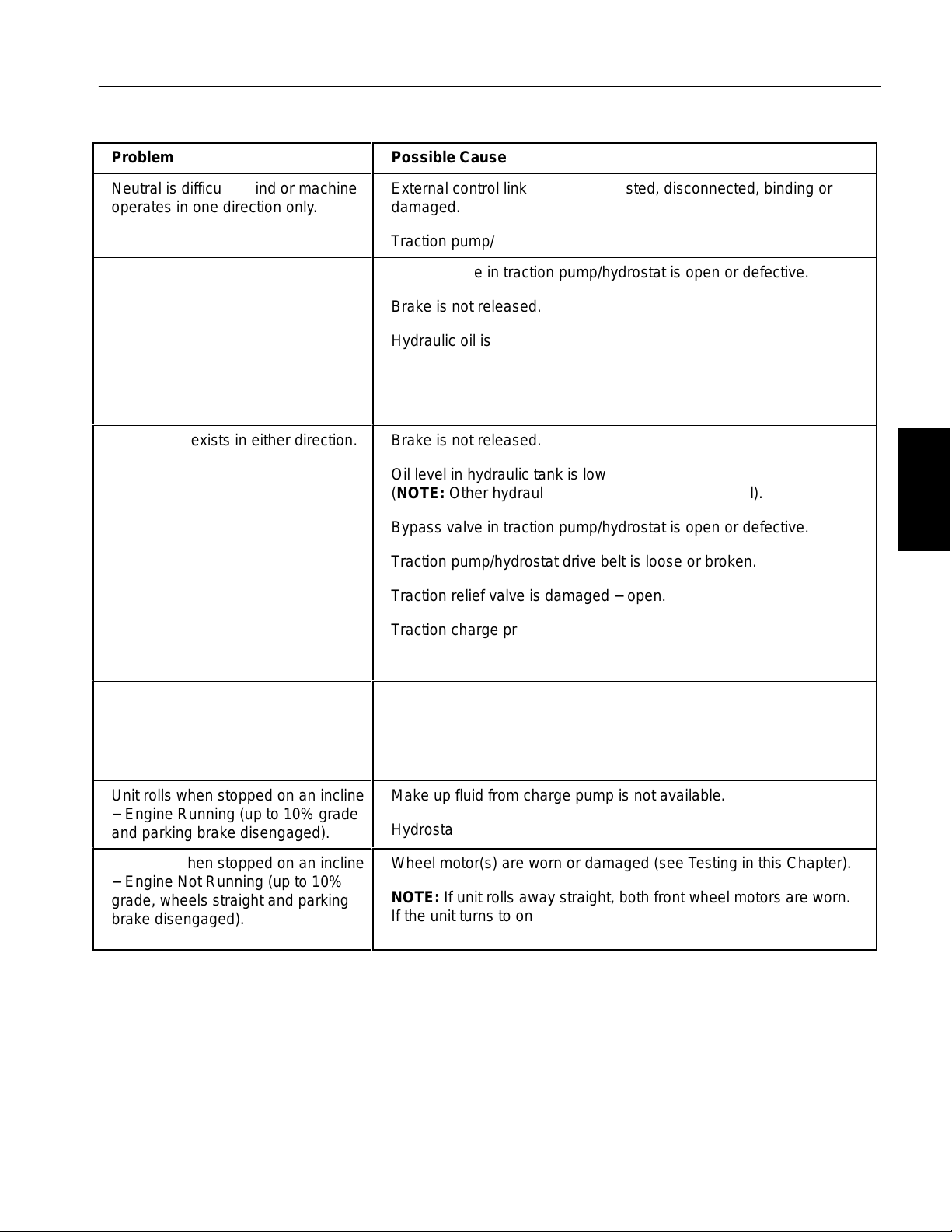
Traction Circuit Problems
Problem
Neutral is difficult to find or machine
operates in one direction only.
Traction response is sluggish.
No traction exists in either direction.
Possible Cause
External control linkage is misadjusted, disconnected, binding or
damaged.
Traction pump/hydrostat is worn or damaged.
Bypass valve in traction pump/hydrostat is open or defective.
Brake is not released.
Hydraulic oil is very cold.
Traction charge pressure is low.
Traction pump/hydrostat or wheel motor(s) are worn or damaged.
Brake is not released.
Oil level in hydraulic tank is low
(NOTE: Other hydraulic systems are affected as well).
Bypass valve in traction pump/hydrostat is open or defective.
Traction pump/hydrostat drive belt is loose or broken.
Traction relief valve is damaged − open.
System
Hydraulic
Wheel will not turn.
Unit rolls when stopped on an incline
− Engine Running (up to 10% grade
and parking brake disengaged).
Unit rolls when stopped on an incline
− Engine Not Running (up to 10%
grade, wheels straight and parking
brake disengaged).
Traction charge pressure is low.
Traction pump/hydrostat or wheel motor(s) are worn or damaged.
Brakes are binding.
Key on wheel motor shaft is sheared or missing.
Internal parts in wheel motor are damaged.
Make up fluid from charge pump is not available.
Hydrostat check valves are damaged.
Wheel motor(s) are worn or damaged (see Testing in this Chapter).
NOTE: If unit rolls away straight, both front wheel motors are worn.
If the unit turns to one side as it rolls away, the wheel motor on the
outside of the turn is worn.
Reelmaster 3550−D Hydraulic SystemPage 4 − 27
Page 60

Lift Circuit Problems
Problem
Cutting units will not lift or lift slowly.
Cutting units raise, but will not stay
up as the traction units travels
between adjacent fairways or fields.
NOTE: Lift circuit components cannot provide an absolutely perfect
seal. The lift arms will eventually
lower if left in the raised position during storage.
Possible Cause
Engine speed is too low.
Hydraulic tank oil level is low
(NOTE: Other hydraulic systems are affected as well).
An electrical problem exists that prevent lift control manifold solen-
oids from being energized (see Chapter 5 − Electrical System in
this manual)
Lift arm bushings are binding.
Implement relief valve (in steering control valve) is stuck open.
Lift cylinders leak internally.
Gear pump (P2) is worn or damaged
(NOTE: Steering and traction charge systems are affected as well).
Lift circuit hydraulic lines or fittings are leaking.
Lift control manifold cartridge valve(s) has damaged seals or is faulty.
Lift cylinders leak internally.
Cutting units will not lower.
NOTE: To lower the cutting units,
the seat must be occupied and the
mow/transport switch must be in the
MOW position.
Lift arm pivots are binding.
An electrical problem exists that prevents the solenoid valve (S1) in
lift control manifold from being energized (See Chapter 5 − Electrical System in this manual).
Solenoid valve (S1) in lift control manifold is faulty.
Lift cylinder(s) for affected cutting unit(s) is damaged.
Reelmaster 3550−DHydraulic System Page 4 − 28
Page 61

Steering Circuit Problems
Problem
Steering inoperative or sluggish
Turning steering wheel turns machine in the wrong direction.
Possible Cause
Oil level in hydraulic reservoir is low
(NOTE: Other hydraulic systems are affected as well).
Steering components (e.g. steering fork assembly, steering cylinder
ends) are worn or binding.
Relief valve in steering control valve is damaged − open.
Steering cylinder leaks internally.
Steering control valve is worn or damaged (see Troubleshooting
Guide in the Sauer/Danfoss Steering Unit Type OSPM Service
Manual.).
Gear pump (P2) is worn or damaged
(NOTE: The lift/lower and traction charge circuits are affected as
well).
Hoses to the steering cylinder are reversed.
System
Hydraulic
Reelmaster 3550−D Hydraulic SystemPage 4 − 29
Page 62

Mow Circuit Problems
Problem
Gear pump is noisy (cavitation).
None of the cutting reels will turn.
NOTE: To engage the mow circuit,
the seat must be occupied, the cutting units must be fully lowered, the
mow/transport switch must be in the
MOW position and the reel enable/
disable switch must be in the ENABLE position.
Poor after−cut appearance (cutting
blades(s) turn too slowly).
NOTE: If possible, have another
person observe the machine while
mowing in dense turf prior to hydraulic testing. A bad reel motor
will run slower, produce fewer clippings, and may cause marcelling
(a washboard appearance) on the
turf.
Possible Cause
Hydraulic tank oil level is low
(NOTE: Other hydraulic systems are affected as well).
Suction line is restricted.
Suction line has an air leak.
Solenoid valve (PRV) is stuck open.
An electrical problem exists that prevents the PRV solenoid valve in
mow control manifold from being energized (See Chapter 5 − Electrical System in this manual).
Gear pump is worn or damaged.
All Cutting Units:
Flow control (FC) in mow control manifold requires adjustment.
Solenoid valve (PRV) is faulty.
Gear pump (P1) is inefficient (see Testing in this chapter).
One or more Cutting Units:
Cutting unit motor has internal leakage (see Testing in this
chapter).
Rear Cutting Units:
Relief valve (RV) is out of adjustment or faulty.
Single Cutting Unit:
Cutting unit reel bearing(s) is (are) damaged.
Reelmaster 3550−DHydraulic System Page 4 − 30
Page 63

Testing
The most effective method for isolating problems in the
hydraulic system is by using hydraulic test equipment
such as pressure gauges and flow meters in the various
hydraulic circuits to perform various operational checks
(See the Special Tools section in this chapter).
Remember that pressure specifications that appear on
hydraulic schematics are the design specifications for
the specific component. Actual system pressure will
vary depending on oil temperature, the location of the
test port, and the specific components used in the hydraulic circuit.
IMPORTANT: The hydraulic test procedures listed
in this manual represent actual performance for this
machine. To correctly measure product or component performance, be sure to follow the test procedures provided.
Before Performing Hydraulic Tests
CAUTION
All testing should be performed by two (2)
people. One person should be in the seat to operate the machine, and the other should read and
record test results.
1. Clean machine thoroughly before disconnecting or
disassembling any hydraulic components. Always keep
in mind the need for cleanliness when working on hydraulic equipment. Hydraulic fluid contamination will
cause excessive wear of components.
2. Put metal caps or plugs on any hydraulic lines left
open or exposed during testing or while hydraulic components are removed.
All obvious areas such as fluid supply, filter, binding linkages, loose fasteners, or improper adjustments must be
checked before assuming that a hydraulic component is
the source of the problem.
Precautions for Hydraulic Testing
WARNING
Keep body and hands away from pin hole leaks
or nozzles that eject hydraulic fluid under high
pressure. Do not use hands to search for
leaks; use paper or cardboard. Hydraulic fluid
escaping under pressure can have sufficient
force to penetrate the skin and cause serious
injury. If fluid is injected into the skin, it must
be surgically removed within a few hours by a
doctor familiar with this type of injury. Gangrene may result from such an injury.
CAUTION
WARNING
Before disconnecting or performing any work
on the hydraulic system, all pressure in the
system must be relieved. See Relieving Hydraulic System Pressure in the General Information section.
3. The engine must be in good operating condition. Use
a phototach (non−contact tachometer) when performing
a hydraulic test. Engine speed can affect the accuracy
of the test readings. Monitor engine RPM during hydraulic testing. Use the information below when performing hydraulic system tests. If engine RPM is above
or below the specified speed during a test, you will need
to adjust the expected hydraulic performance parameters (aprox. 3% per 100 engine rpm at full throttle)
IMPORTANT: Hydraulic component output volume
relates directly to engine RPM. For every 100 engine
rpm the following component output volumes will
change by the volume listed.
Hydrostat: 100 engine RPM = 0.59 GPM or 76.6 oz.
(2265 cc) of hydraulic fluid displaced per minute
System
Hydraulic
Failure to use gauges with recommended pressure (psi) rating as listed in test procedures
could result in damage to the gauge and possible
personal injury from leaking hot hydraulic fluid.
Reelmaster 3550−D Hydraulic SystemPage 4 − 31
Gear Pump (P1): 100 engine RPM = 0.24 GPM or
30.8 oz. (912 cc) of hydraulic fluid displaced per
minute
Gear Pump (P2): 100 engine RPM = 0.14 GPM or
17.5 oz. (519 cc) of hydraulic fluid displaced per
minute
Page 64

NOTE: Engine−to−Pump ratio is 1:0.96. In other words,
1 engine RPM = 0.96 pump RPM.
10.All hydraulic tests should be made with the hydraulic
fluid at normal operating temperature.
4. The inlet and the outlet hoses must be properly connected and not reversed (hydraulic tester with pressure
and flow capabilities) to prevent damage to the hydraulic
tester or components.
5. When using a hydraulic tester with pressure and flow
capabilities, open load valve completely in the hydraulic
tester to minimize the possibility of damaging components.
6. Install fittings finger tight and far enough to make
sure that they are not cross−threaded before tightening
them with a wrench.
7. Position hydraulic tester hoses to prevent moving
machine parts from contacting and damaging the hoses
or tester.
8. Check fluid level in the hydraulic tank. After connecting test equipment, make sure tank is full.
9. Check control linkages for improper adjustment,
binding, or broken parts.
Hydraulic Test Selection
Before beginning any hydraulic test, identify if the problem is related to the traction circuit, cutting (mow) circuit
or steering and lift/sidewinder circuit. Once the faulty
system has been identified, perform tests that relate to
that circuit.
If a traction circuit problem exists, consider performing
one or more of the following tests: Charge Pressure
Test, Wheel Motor Efficiency Test, and/or Piston Pump/
Hydrostat Flow and Relief Valve Tests.
If a cutting (mow) circuit problem exists, consider performing one or more of the following tests: Circuit Pressure Test, Reel Motor Efficiency/Case Drain Test, Mow
Control Manifold Relief Pressure Test, and/or Gear
Pump (P1) Test.
If a steering or lift/sidewinder circuit problem exists, consider performing one or more of the following tests: Gear
Pump (P2) Flow Test, Relief Valve Pressure Test, and/or
Steering Control Valve and Steering Cylinder Test.
Reelmaster 3550−DHydraulic System Page 4 − 32
Page 65

This page is intentionally blank.
System
Hydraulic
Reelmaster 3550−D Hydraulic SystemPage 4 − 33
Page 66

Traction Circuit Testing − Charge Pressure Test
FRONT
FRONT
TRACTION WHEEL MOTORS
FORWARD
TESTER WITH
PRESSURE GUAGE
AND FLOW METER
LOWER
PORT
REAR
BYPASS
VALVE
UPPER
PORT
TEE CONNECTOR
PRESSURE GUAGE
FROM LIFT CONTROL
MANIFOLD (T) PORT
AND
G2
C2
G1
3500 PSI
200−300
PSI
100−150 PSI
CHARGE RELIEF
HYDROSTAT
TO MOW CONTROL
MANIFOLD (P) PORT
TO STEERING CONTROL
VALVE (P) PORT
P1
P2
GEAR PUMP
SUCTION
STRAINER
High Pressure
Low Pressure
Return or Suction
Flow
Reelmaster 3550−DHydraulic System Page 4 − 34
Page 67

Traction Circuit Testing − Charge Pressure Test:
The charge pressure test is the first in a series of tests
recommended to determine traction circuit performance. A charge pressure drop of more than 20% indic-
ates an internal leak in the piston pump/hydrostat.
Continued unit operation can generate excessive heat,
cause damage to seals and other components in the hydraulic system, and affect overall machine performance.
1
2
Special Equipment Required:
S Pressure Gauge
S Flow Meter w i t h P r e s s u re G a u g e that has at least
an 18 GPM (68 LPM) capacity.
S Phototach (non−contact tachometer).
1. Park machine on a level surface with the cutting units
lowered and the reel engage/disengage switch is in the
disengage position. Make sure engine is off and the
parking brake is engaged.
2. Read Precautions for Hydraulic Testing in this
chapter.
3. Make sure that traction pedal is adjusted to the neutral position.
4. Disconnect the upper hose at the tee fitting on the
piston pump/hydrostat. This hose comes from the steering control valve (T) port (Fig. 25).
5. Install a T−connector and pressure gauge between
the fitting and disconnected hose.
6. Disconnect hose from the lower hydraulic fitting on
the engine side of the hydrostat (Fig. 26).
7. Install tester in series with the pump and the disconnected hose. Make sure the tester flow control valve is
fully open.
8. Attach a heavy chain to the rear of the machine frame
and an immovable object to prevent the machine from
moving during testing.
9. Chock the wheels to prevent wheel rotation during
testing.
10.Start engine. Move throttle to full speed (3220 +
50
RPM).
11.Make sure hydraulic fluid is at normal operating temperature by operating the machine for approximately 10
minutes.
12.Verify with a phototach that the pump speed is approximately 3090 RPM.
Figure 25
1. Hydraulic tee fitting 2. Piston pump
2
1
Figure 26
1. Lower hydraulic fitting 2. Piston pump
13.Record reading on pressure gauge from the lift control manifold (T) port. Charge pressure (without load)
should read from 150 to 200 PSI (10.3 to13.8 Bar). If
charge relief pressure specification is not met, consider
the following:
A. Gear pump (P2) is faulty (steering/lift circuit performance will also be affected). Test gear pump (P2)
flow (see Gear Pump (P2) Flow Test in this chapter).
B. The piston pump charge relief valve is faulty. Repair or replace the piston pump charge relief valve
(see Piston Pump Service in this chapter).
14.Sit in the operator’s seat, release the parking brake,
and slowly depress the forward traction pedal until 1000
to 1500 PSI (68.9 to 103.4 Bar) is reached on the flow
meter pressure gauge.
15.Record reading on pressure gauge from lift control
manifold (T) port (under load). Charge pressure (under
load) should not drop more than 20% when compared
to charge pressure (without load) recorded in step 13.
If specifications are not met, perform Piston Pump/Hydrostat Flow and Traction Relief Pressure Test as outlined in this chapter.
16.Release traction pedal, move throttle to low speed
and turn the engine off.
System
Hydraulic
Reelmaster 3550−D Hydraulic SystemPage 4 − 35
Page 68

Traction Unit Testing − Wheel Motor Efficiency Tests
LOWER
PORT
G2
FRONT WHEEL MOTOR TEST
(together)
FRONT
FRONT
TRACTION WHEEL MOTORS
FORWARD
TESTER WITH
PRESSURE GUAGE
AND FLOW METER
BYPASS
VALVE
3500 PSI
REAR
UPPER
PORT
G1
FRONT WHEEL MOTOR TEST
FRONT
FRONT
FORWARD
PRESSURE GUAGE
AND FLOW METER
PISTON PUMP
(HYDROSTAT)
LOWER PORT
REAR WHEEL MOTOR TEST
(individually)
REAR
TRACTION WHEEL MOTORS
TESTER WITH
PISTON PUMP
(HYDROSTAT)
UPPER PORT
C2
FROM
LIFT
CONTROL
MANIFOLD
(T) PORT
100−150 PSI
CHARGE RELIEF
HYDROSTAT
200−300
PSI
TO GEAR PUMP
SUCTION
THROUGH
CASE DRAIN
Figure 27
FRONT
FRONT
FORWARD
PISTON PUMP
(HYDROSTAT)
LOWER PORT
REAR
TRACTION WHEEL MOTORS
TESTER WITH
PRESSURE GUAGE
AND FLOW METER
PISTON PUMP
(HYDROSTAT)
UPPER PORT
High Pressure
Low Pressure
Return or Suction
Flow
Reelmaster 3550−DHydraulic System Page 4 − 36
Page 69

Traction Circuit Testing − Wheel Motor Efficiency
Test:
Wheel motor efficiency is the second in a series of tests
recommended to determine traction circuit performance. Hydraulic fluid flow o f 1.5 GPM (5.7 LPM) or more
through a stationary wheel motor under load indicates
an internal leak in the wheel motor. A worn wheel motor
is less efficient. Eventually, enough fluid by−pass will
cause the wheel motor to stall under heavy load conditions. Continued operation can generate excessive
heat, cause damage to seals and other components in
the hydraulic system, and affect overall machine performance.
2
1
Figure 28
1. Lower hydraulic fitting 2. Piston pump
There are moments during wheel motor operation (geroller position) when fluid flow through the motor is less
restricted. If a wheel motor is tested in this position, the
test results will be higher should not be used to determine wheel motor efficiency. Test wheel motors in three
(3) different wheel positions to obtain accurate test results. Record test readings for all three (3) wheel positions.
Hydraulic fluid flows through both front wheel motors (in
parallel) before passing through the rear wheel motor (in
series). In this configuration, the rear wheel motor can
mask front wheel motor performance issues, and the
front wheel motors can mask rear wheel motor performance issues. Start by testing both front wheel motors together, then individually if necessary. Finish by testing
the rear wheel motor.
Special Equipment Required:
S Pressure Gauge
S Flow Meter w i t h P r e s s u re G a u g e that has at least
an 18 GPM (68 LPM) capacity
S Phototach (non−contact tachometer)
1. Park machine on a level surface with the cutting units
lowered and the reel engage/disengage switch is in the
disengage position. The engine should be off and the
parking brake engaged.
2. Read Precautions for Hydraulic Testing in this
chapter.
Front Wheel Motor Test:s
Hydraulic fluid flows through both front wheel motors (in
parallel) before passing through the rear wheel motor (in
series). To accurately test the front wheel motors, the
rear wheel motor must be removed from the traction circuit.
1. Disconnect hose from the lower hydraulic fitting on
the bottom of the hydrostat (Fig. 28).
NOTE: An alternate testing location would be at the hydraulic hose from the hydrostat and the hydraulic tube
supplying the front wheel motors under the left floor
plate.
2. Install flow tester between the hydrostat and the disconnected hose. Make sure the tester flow control valve
is fully open.
3. Disconnect both hydraulic lines from the rear wheel
motor, then reconnect the lines to each other. Plug ports
in wheel motor to prevent contamination.
4. Chock front wheels to prevent wheel rotation.
5. Start engine. Move throttle to full speed (3220 +
50
RPM).
6. Make sure hydraulic fluid is at normal operating temperature by operating the machine for approximately 10
minutes. Make sure the hydraulic tank is full.
System
Hydraulic
3. Make sure that traction pedal is adjusted to the neutral position.
4. Attach a heavy chain to the rear of the machine frame
and an immovable object to prevent the machine from
moving during testing.
Reelmaster 3550−D Hydraulic SystemPage 4 − 37
Page 70

7. Verify with a phototach that the pump speed is approximately 3090 RPM.
CAUTION
Use extreme caution when performing wheel motor tests. The wheel motors will be trying to move
the machine forward.
8. Sit in the operators seat, release the parking brake,
and set the Mow/Transport slide to the transport position.
9. Slowly depress forward traction pedal until 1000 to
1500 PSI (68.9 to 103.4 Bar) is displayed on the pressure gauge.
Flow meter should read less than 1.5 GPM (5.7
LPM).
10.Release traction pedal, shut engine off, and record
test results.
Flow meter should read less than 1.5 GPM (5.7
LPM).
17.Release traction pedal, shut engine off, and record
test results.
18.Rotate front wheel 120 degrees and retest. Repeat
this procedure until wheel motor has been tested in
three (3) different positions.
19.Reconnect hydraulic lines to front wheel motor and
repeat procedure for remaining front wheel motor.
20.If specifications are not met, repair or replace worn
wheel motor.
11.Rotate each front wheel 120 degrees and retest. Repeat this procedure until each wheel motor has been
tested in three (3) different positions.
Proceed to testing rear wheel motor If test results are
within specification. If specifications are not met, test
front wheel motors individually as follows:
12.Disconnect hydraulic lines from front wheel motor
that is not being tested. Cap disconnected hydraulic
lines and plug ports in wheel motor to prevent contamination.
13.Chock front wheel being tested to prevent wheel rotation.
14.Start engine. Move throttle to full speed.
CAUTION
Use extreme caution when performing wheel motor tests. The wheel motors will be trying to move
the machine forward.
15.Sit in the operators seat, release the parking brake,
and set the Mow/Transport slide to the transport position.
16.Slowly depress forward traction pedal until 1000 to
1500 PSI (68.9 to 103.4 Bar) is displayed on the pressure gauge.
Reelmaster 3550−DHydraulic System Page 4 − 38
Page 71

Rear Wheel Motor Test:
3. Raise off the floor and support both front wheels.
Hydraulic fluid flows through both front wheel motors (in
parallel) before passing through the rear wheel motor (in
series). To accurately test the rear wheel motor, the front
wheel motors must be allowed to rotate.
1. Disconnect hose from the upper hydraulic fitting of
the rear wheel motor (Fig. 29).
2
RIGHT
FRONT
1
Figure 29
1. Rear wheel motor 2. Upper fitting
2. Install flow tester between the disconnected hydraulic hose and the rear wheel motor. Make sure the tester
flow control valve is fully open.
4. Chock rear wheel to prevent wheel rotation.
5. Start engine. Move throttle to full speed.
CAUTION
Use extreme caution when performing wheel motor tests. The wheel motors will be trying to move
the machine forward.
6. Sit in the operators seat, release the parking brake,
and set the Mow/Transport slide to the transport position.
7. Slowly depress forward traction pedal until 1000 to
1500 PSI (68.9 to 103.4 Bar) is displayed on the pressure gauge.
Flow meter should read less than 1.5 GPM (5.7
LPM).
8. Release traction pedal, shut engine off, and record
test results.
9. Rotate rear wheel 120 degrees and retest. Repeat
this procedure until wheel motor has been tested in
three (3) different positions.
10.If specifications are not met, repair or replace worn
wheel motor.
System
Hydraulic
WARNING
Before jacking up the machine, review and follow
Jacking Instructions in Chapter 1 − Safety.
Reelmaster 3550−D Hydraulic SystemPage 4 − 39
Page 72

Traction Circuit Testing − Piston Pump/Hydrostat Flow and Relief Pressure Test
FRONT
FRONT
REAR
TRACTION WHEEL MOTORS
FORWARD
TESTER WITH
PRESSURE GUAGE
AND FLOW METER
LOWER
PORT
BYPASS
VALVE
UPPER
PORT
FROM LIFT CONTROL
MANIFOLD (T) PORT
G2
C2
G1
3500 PSI
200−300
PSI
100−150 PSI
CHARGE RELIEF
HYDROSTAT
TO MOW CONTROL
MANIFOLD (P) PORT
TO STEERING CONTROL
VALVE (P) PORT
P1
P2
GEAR PUMP
SUCTION
STRAINER
High Pressure
Low Pressure
Return or Suction
Flow
Reelmaster 3550−DHydraulic System Page 4 − 40
Page 73

Traction Circuit Testing − Piston Pump/Hydrostat
Flow and Relief Pressure Test:
The hydrostat flow test is the third in a series of tests recommended to determine traction circuit performance.
The final traction circuit test is verifying the hydrostat relief valve operation. This test compares fluid flow at No
Load with fluid flow Under Load. A drop in flow under
load of more than 12% indicates an internal leak or malfunctioning relief valve in the piston pump/hydrostat. A
worn hydrostat or malfunctioning relief valve is less efficient. Eventually, enough fluid by−pass will cause the
unit to stall under heavy load conditions. Continued operation can generate excessive heat, cause damage to
seals and other components in the hydraulic system,
and affect overall machine performance.
Special Equipment Required:
S Pressure Gauge
S Flow Meter w i t h P r e s s u re G a u g e that has at least
an 18 GPM (68 LPM) capacity.
S Phototach (non−contact tachometer).
1. Park machine on a level surface with the cutting units
lowered and the reel engage/disengage switch in the
disengage position. The engine should be off and the
parking brake engaged.
2
1
Figure 30
1. Lower hydraulic fitting 2. Piston pump
10.Sit in the operator’s seat, release the parking brake,
and set the Mow/Transport slide to the transport position.
CAUTION
Use extreme caution when performing hydrostat
flow tests. The traction unit wheels will be rotating during the test.
11.Verify pump flow at No Load as follows:
System
Hydraulic
2. Read Precautions for Hydraulic Testing in this
chapter.
3. Make sure that traction pedal is adjusted to the neutral position.
WARNING
Before jacking up the machine, review and follow
Jacking Instructions in Chapter 1 − Safety.
4. Raise of f the floor and support both front wheels and
the rear wheel.
5. Disconnect hose from the lower hydraulic fitting on
the engine side of the hydrostat (Fig. 30).
6. Install tester in series with the pump and the disconnected hose. Make sure the tester flow control valve is
fully open.
7. Start engine. Move throttle to full speed (3220 + 50
RPM).
8. Make sure hydraulic fluid is at normal operating temperature by operating the machine for approximately 10
minutes. Make sure the hydraulic tank is full.
9. Verify with a phototach that the pump speed is approximately 3090 RPM.
A. Slowly depress forward traction pedal to full forward position.
B. Record tester pressure and flow readings. Unrestricted pump output should be approximately 18
GPM (69 LPM) at 650 PSI (44.8 Bar).
12. Verify pump flow Under Load as follows:
A. Slowly depress forward traction pedal to full for-
ward position.
B. Apply an additional load of 1000 to 1500 PSI
(68.9 to 103.4 Bar) by slowly closing the flow meter.
The flow meter pressure gauge should read 1700 to
2100 PSI (117.2 to 144.8 Bar).
C. Record tester pressure and flow readings.
13.Verify traction relief valve operation as follows:
A. Return the traction pedal to neutral.
B. Fully close the flow meter flow control valve.
C. Slowly set traction pedal to full forward position.
D. Record tester pressure reading.
System pressure should reach 3600 to 3650 PSI
(248 to 251 Bar) before the relief valve opens.
Reelmaster 3550−D Hydraulic SystemPage 4 − 41
Page 74

NOTE: The relief valve setting is 3500 PSI (241
Bar). An additional 100 to 200 PSI (6.9 to 10.3 Bar)
is necessary to overcome system charge pressure
before the relief valve opens.
15.The Under Load test flow reading (step 12.) should
not drop more than 12% when compared to the No
Load test flow reading (step 11.). A difference of more
than 12% may indicate:
E. Release traction pedal, open flow control valve
fully, move throttle to low speed and turn the engine
off.
14.If relief pressure can not be met or is greater than
specified, the traction relief valve is faulty and should be
replaced.
A. The traction belt is worn and/or slipping.
B. The piston pump/hydrostat is worn and should be
repaired or replaced.
16.Disconnect tester and reconnect hose to pump.
Reelmaster 3550−DHydraulic System Page 4 − 42
Page 75

This page is intentionally blank.
System
Hydraulic
Reelmaster 3550−D Hydraulic SystemPage 4 − 43
Page 76

Cutting Unit Circuit Testing − Pressure Test
BACKLAP
SWITCH
(SW)
REEL #4
FC
REEL #1 REEL #5 REEL #2 REEL #3
MOW CONTROL
M1
M2
MV
CV1
OR1
.050”
MANIFOLD
OR2
.020”
1500 PSI
RV
PRESSURE
TO
HYDRAULIC
TANK
GAUGE
G
P
FROM
GEAR PUMP
(P1)
LC
M3
PRV
3000 PSI
T
TO
OIL COOLER
High Pressure
Low Pressure
Return or Suction
Flow
Reelmaster 3550−DHydraulic System Page 4 − 44
Page 77

Cutting Unit Circuit T esting − Pressure Test:
)
Cutting unit circuit pressure is the first in a series of tests
recommended to check cutting unit circuit performance.
The results from this test will help determine which component(s) are the cause of cutting unit performance issues.
Special Equipment Required:
S Pressure Gauge with extension hose
S Phototach (non−contact tachometer).
1. Park machine on a level surface with the cutting units
lowered, the reel engage/disengage switch in the DISENGAGE position, and the mow/transport switch in the
MOW position. Make sure engine is off and the parking
brake is disengaged.
2. Make sure backlap knob on the hydraulic manifold is
in the MOW position. Make sure reel speed knob is set
for typical mowing conditions.
3. Read Precautions for Hydraulic Testing in this
chapter.
4. Remove cap from test fitting at mow control manifold
port (OR1/G) and install a pressure gauge with hydraulic
hose to the test fitting (Fig. 31).
CAUTION
Keep away from cutting units during test to prevent personal injury from the cutting blades.
5. Sit in the Operator’s seat, start the engine, and move
throttle to full speed (3220 +
6. Make sure hydraulic fluid is at normal operating temperature by operating the machine for approximately 10
minutes. Make sure the hydraulic tank is full.
7. Verify with a phototach that the pump speed is approximately 3090 RPM.
8. Set the cutting unit speed control to #9 (maximum)
and engage the cutting units.
When engaged, the cutting circuit pressure may exceed
manifold relief valve pressure setting of 3000 PSI (207
Bar) momentarily opening the relief valve. Circuit pressure should then stabilize at approximately 1200 PSI
(83 Bar).
50 RPM).
2
1
Figure 31
1. Mow control manifold 2. Test fitting (port OR1/G
9. Safely secure the test pressure gauge and operate
the machine under your specific mowing conditions.
Monitor test gauge while mowing. Cutting unit circuit
pressure should be approximately: 1500 to 2000 PSI
(103 to 138 Bar) under low to normal load conditions.
10.Disengage cutting units, move throttle to low speed
and shut off engine.
11. If pressure readings are within specifications and
cutting unit performance is still in question, test cutting
unit motors individually (see Cutting Unit Circuit Testing
− Reel Motor Efficiency/Case Drain Test).
12.If pressure specifications are not met, consider the
following:
A. Proportional relief valve (PRV) is faulty (see Cutting Unit Circuit Testing − Proportional Relief Valve
(PRV) Pressure Test in this chapter).
B. Relief valve (RV) is faulty (see Cutting Unit Circuit
Testing − Relief Valve (RV) Pressure Test in this
chapter).
C. Logic Cartridge (LC) Is faulty (see Control Manifold Cartridge Valve Service in this chapter).
D. Gear pump (P1) is faulty (see Cutting Unit Circuit
Testing − Gear Pump (P1) Flow Under Load Test in
this chapter).
13.Disconnect test equipment from hydraulic manifold.
System
Hydraulic
Reelmaster 3550−D Hydraulic SystemPage 4 − 45
Page 78

Cutting Unit Circuit Testing − Reel Motor Efficiency/Case Drain Test
TO
HYDRAULIC
TANK
Toro # TOR4077
REEL #4 REEL #1 REEL #5 REEL #2 REEL #3
FROM
MOW CONTROL
MANIFOLD
PORT (M1)
MEASURING
CONTAINER
TESTER
WITH
PRESSURE GAUGE
AND FLOW METER
NOTE: CONFIGURATION FOR TESTING REEL MOTOR #4 SHOWN
TO
MOW CONTROL
MANIFOLD
PORT (M2)
High Pressure
Low Pressure
Return or Suction
Flow
TO
MOW CONTROL
MANIFOLD
PORT (M3)
CUTTING UNIT LOCATIONS
1
2
1 1
2
#4 #5
#2
FRONT
1. Reel motor location 2. Weight location
#1
#3
2 11
Reelmaster 3550−DHydraulic System Page 4 − 46
Page 79

Cutting Unit Circuit Testing − Reel Motor Efficiency/
Case Drain Test
The reel motor efficiency/case drain test is the second
in a series of tests recommended to check cutting unit
circuit performance. Over a period of time, a reel motor
can wear internally. This test measures case drain
volume while restricting flow across the motor ports.
Case drain volume under load of more than 9% of total
motor flow indicates the gears and wear plates in the
motor have worn. A worn motor may by−pass hydraulic
fluid to its case drain causing the motor to be less efficient. Eventually, enough fluid loss will cause the reel
motor to stall under heavy cutting conditions. Continued
operation with a worn, inefficient motor can generate excessive heat, cause damage to seals and other components in the hydraulic system, and affect quality of cut.
NOTE: One method to find a failing or malfunctioning
cutting unit motor is to have another person observe the
machine while mowing in dense turf. A bad motor will run
slower, produce fewer clippings and may cause a different appearance on the turf.
Special Equipment Required:
S Flow Meter w i t h P r e s s u re G a u g e that has at least
a 12 GPM (45 LPM) capacity.
S Phototach (non−contact tachometer).
1. Make sure hydraulic fluid is at normal operating temperature by operating the machine for approximately 10
minutes. Make sure the hydraulic tank is full.
6. Install hydraulic tester between the motor and the
disconnected return hose. Make sure the tester flow
control valve is fully open.
7. Make sure backlap knob on the hydraulic manifold is
in the MOW position and reel speed is set to maximum.
8. Disconnect hose from reel motor case drain at the
hydraulic tube (#1 cutting unit), or from the bulkhead fitting (#2, 3, 4, & 5 cutting units). Cap the hydraulic tube
or bulkhead fitting to prevent system contamination.
9. Place open end of disconnected case drain hose into
a drain pan.
10.Two people are required to complete the following
steps. One person should sit in the operator’s seat and
operate the machine while another person reads the
tester and measures reel motor case drain volume.
11.Start the engine, and move throttle to full speed
(3220 +
12.Verify with a phototach that the pump speed is ap-
proximately 3090 RPM.
50 RPM).
CAUTION
Keep away from reels during test to prevent personal injury from the rotating reel blades.
System
Hydraulic
2. Park the machine on a level surface with the cutting
units lowered and the reel enable/disable switch in the
disable position. Make sure engine is off and the parking
brake is disengaged.
3. Read Precautions for Hydraulic Testing in this
chapter.
4. Make sure that traction pedal is adjusted to the neutral position.
NOTE: The cutting unit motors are connected in series.
If a faulty reel motor is not obvious (based on quality of
cut issues) you may have to test all the reel motors in the
circuit. If testing all reel motors, start with the first motor
in the series (#4 cutting unit).
5. Hydraulic oil passes through each reel motor from
the front to the rear. Disconnect the return hose from the
motor (hose at the rear of the reel motor).
13.Engage cutting units and slowly close tester flow
control valve until 1200 PSI (82.7 Bar) is obtained.
14.Hold disconnected motor case drain hose into a con-
tainer graduated in ounces or milliliters (e.g. Toro
#TOR4077) and collect hydraulic fluid for 30 seconds.
After 30 seconds, remove hose end from container.
15.Record amount of fluid collected in the container.
16.Disengage cutting units, set throttle to low speed,
and stop engine.
17.If volume is more than 43 oz (1265 milliliters), repair
or replace the tested reel motor.
18.Remove tester and reconnect hydraulic hoses.
19.Check hydraulic fluid level (see Traction Unit Operat-
or’s Manual).
20.Repeat test for remaining reel motors as needed.
Reelmaster 3550−D Hydraulic SystemPage 4 − 47
Page 80

Cutting Unit Circuit Testing − Proportional Relief Valve (PRV) Pressure Test
BACKLAP
SWITCH
(SW)
REEL #4
PRESSURE GAUGE
AND FLOW METER
FC
REEL #1 REEL #5 REEL #2 REEL #3
TESTER
WITH
M1
M2
MV
CV1
OR1
.050”
MOW CONTROL MANIFOLD
OR2
.020”
1500 PSI
RV
TO
HYDRAULIC
TANK
G
GEAR PUMP
FROM
(P1)
LC
PRV
3000 PSI
P
T
TO
OIL COOLER
M3
High Pressure
Low Pressure
Return or Suction
Flow
Reelmaster 3550−DHydraulic System Page 4 − 48
Page 81

Cutting Unit Circuit Testing − Proportional Relief
e
Valve (PRV) Pressure Test:
Test the performance of the mow control manifold proportional relief valve (PRV) to make sure that the maximum amount of fluid is available to the cutting unit motors
up to the set relief pressure. This test also ensures that
pump (P1) is capable of generating enough pressure to
open a properly functioning proportional relief valve.
Special Equipment Required:
S Flow Meter w i t h P r e s s u re G a u g e that has at least
a 12 GPM (45 LPM) capacity.
S Phototach (non−contact tachometer).
1. Park machine on a level surface with the cutting units
lowered, reel engage/disengage switch in the disengage position, and the mow/transport switch in the
MOW position. Engine should be off and the parking
brake disengaged.
2. Read Precautions for Hydraulic Testing in this
chapter.
2
1
Figure 32
1. Mow control manifold 2. Proportional relief valv
(PRV)
3. Disconnect the inlet hose from the front hydraulic fitting of the front left (#4) reel motor (Fig. 33).
4. Install tester between the hose and hydraulic fitting.
Make sure the flow control valve on tester is fully open.
5. Make sure backlap knob on the hydraulic manifold is
in the MOW position, and the reel speed knob is set to
maximum.
6. Start the engine, and move throttle to full speed
(3220 +
7. Make sure hydraulic fluid is at normal operating temperature by operating the machine for approximately 10
minutes.
8. Verify with a phototach that the pump speed is approximately 3090 RPM.
50 RPM).
CAUTION
Keep away from reels during test to prevent personal injury from the rotating reel blades.
9. Engage cutting units.
10.Watch pressure gauge carefully while slowly closing
the flow control valve.
2
FRONT
1. Reel motor #4 2. Inlet hose
13.If specification is met, test pump (P1) flow (see Cutting Unit Circuit Testing − Gear Pump (P1) Flow Test in
this chapter) If specification is not met, test relief valve
(PRV) solenoid, clean or replace valve (see Hydraulic
Manifold Service in this chapter) and retest.
14.Disconnect tester and reconnect hydraulic hose.
1
#1#4 #5
#2 #3
Figure 33
System
Hydraulic
11.System pressure should reach 3000 PSI (207 Bar)
before the relief valve opens.
12.Set throttle to low speed and shut off engine.
Reelmaster 3550−D Hydraulic SystemPage 4 − 49
Page 82

Cutting Unit Circuit Testing − Mow Control Manifold Relief Valve (RV) Pressure Test
REEL #4
BACKLAP
SWITCH
(SW)
REEL #1 REEL #5 REEL #2 REEL #3
M1
FC
M2
MV
CV1
OR1
.050”
TESTER
WITH
PRESSURE GAUGE
AND FLOW METER
MOW CONTROL MANIFOLD
OR2
.020”
1500 PSI
RV
TO
HYDRAULIC
TANK
G
P
FROM
GEAR PUMP
(P1)
PRV
3000 PSI
LC
T
TO
OIL COOLER
M3
High Pressure
Low Pressure
Return or Suction
Flow
Reelmaster 3550−DHydraulic System Page 4 − 50
Page 83

Cutting Unit Circuit Testing − Mow Control Manifold
Relief Valve (RV) Pressure Test:
If a rear cutting unit suddenly becomes obstructed during operation, mow control manifold relief valve (RV)
protects the obstructed cutting unit from additional damage by diverting the oil flow from the front cutting units.
Test the performance of the mow control manifold relief
valve (R V ) to make sure that the relief valve opens at the
specified pressure.
Special Equipment Required:
S Flow Meter w i t h P r e s s u re G a u g e that has at least
a 12 GPM (45 LPM) capacity.
S Phototach (non−contact tachometer).
1. Park machine on a level surface with the cutting units
lowered, reel engage/disengage switch in the disengage position, and the mow/transport switch in the
MOW position. Engine should be off and the parking
brake disengaged.
2. Read Precautions for Hydraulic Testing in this
chapter.
3. Disconnect the inlet hose for the rear left (cutting unit
#2) reel motor at the frame bulkhead fitting (Fig. 34).
1
2
1. Reel motor #2
inlet hose
#1#4 #5
#2 #3
Figure 34
2. Frame bulkhead fitting
FRONT
System
Hydraulic
4. Install tester between the disconnected hydraulic
hose and the bulkhead fitting. Make sure the tester flow
direction is from the bulkhead fitting toward the reel motor, and that the tester flow control valve is fully open.
5. Make sure backlap knob on the hydraulic manifold is
in the MOW position, and the reel speed knob is set to
maximum.
6. Start the engine, and move throttle to full speed
(3220 +
7. Make sure hydraulic fluid is at normal operating temperature by operating the machine for approximately 10
minutes.
8. Verify with a phototach that the pump speed is approximately 3090 RPM.
50 RPM).
CAUTION
Keep away from reels during test to prevent personal injury from the rotating reel blades.
9. Engage cutting units.
10.Watch pressure gauge carefully while slowly closing
the flow control valve.
1
2
Figure 35
1. Mow control manifold 2. Relief valve (RV)
11.System pressure should reach 1500 PSI (103.4 Bar)
before the relief valve opens.
12.Set throttle to low speed and shut off engine.
13.If specification is met, test pump (P1) flow (see Cutting Unit Circuit Testing − Gear Pump (P1) Flow Test in
this chapter) If specification is not met, adjust relief valve
(RV) (see Adjustments in this chapter) and retest. If specification is still not met, clean or replace relief valve
(RV) (see Hydraulic Manifold Service in this chapter)
and retest.
14.Disconnect tester and reconnect hydraulic hoses.
Reelmaster 3550−D Hydraulic SystemPage 4 − 51
Page 84

Cutting Unit Circuit Testing − Gear Pump (P1) Flow Test
BYPASS
VALVE
FROM LIFT CONTROL
MANIFOLD (T) PORT
G2
C2
G1
3500 PSI
200−300
PSI
100−150 PSI
CHARGE RELIEF
TO MOW CONTROL
MANIFOLD (P) PORT
TO STEERING CONTROL
VALVE (P) PORT
High Pressure
Low Pressure
Return or Suction
Flow
HYDROSTAT
HYDROSTAT
TESTER
WITH PRESSURE GAUGES
AND FLOW METER
P1
P2
GEAR PUMP
SUCTION
STRAINER
Reelmaster 3550−DHydraulic System Page 4 − 52
Page 85

Cutting Unit Circuit Testing − Gear Pump (P1) Flow
1
2
Test:
The gear pump (P1) flow test is the last in a series of
tests recommended to determine cutting unit circuit performance. This test compares fluid flow at No Load with
fluid flow Under Load. A drop in flow under load of more
than 15% indicates the gears and wear plates in the
pump have worn. A worn pump will by−pass hydraulic
fluid and make the pump less efficient. Eventually,
enough fluid loss will occur to cause the cutting unit motors to stall under heavy cutting conditions. Continued
operation with a worn, inefficient pump can generate excessive heat and cause damage to the seals and other
components in the hydraulic system.
Special Equipment Required:
S Flow Meter w i t h P r e s s u re G a u g e that has at least
a 12 GPM (45 LPM) capacity.
S Phototach (non−contact tachometer).
1. Park machine on a level surface with the cutting units
lowered and reel enable/disable switch in the disengage
position. Make sure engine is off and the parking brake
is engaged.
2. Read Precautions for Hydraulic Testing in this
chapter.
3. Disconnect hose connection on the gear pump (P1)
leading to port (P) on the mow control manifold (Fig. 36).
4. Install tester between the gear pump and the disconnected hose.
5. Make sure the flow control valve on the tester is fully
open.
6. Sit in the operator’s seat and start the engine. Move
the throttle to full speed (3220 +
50 RPM).
7. Make sure hydraulic fluid is at normal operating temperature by operating the machine for approximately 10
minutes.
2
RIGHT
FRONT
1
P2
P1
Figure 36
. Gear pump assembly
. To mow control manifold
(P) port
10.Verify pump flow Under Load as follows:
CAUTION
Do not close tester valve fully when performing this test. In this test, the hydraulic tester is
positioned before the manifold relief valve.
Pump damage can occur if the fluid flow is fully
restricted by fully closing the tester flow control valve.
A. Watch flow meter pressure gauge carefully while
slowly closing the flow control valve until 2000 PSI
(137.9 Bar) is obtained on gauge.
B. Record tester pressure and flow readings under
load.
11.Set throttle to low speed and shut off engine.
System
Hydraulic
8. Verify with a phototach that the pump speed is approximately 3090 RPM.
9. Verify pump flow at No Load as follows:
Record tester pressure and flow reading at no load.
Unrestricted pump output should be approximately
7.3 GPM (29.3 LPM).
12.The under load test flow reading (step 10.B) should
not drop more than 15% when compared to no load test
flow reading (step 9.A). A difference in flow of more than
15%, or the inability to achieve specified pressure may
indicate:
A. A restriction in the pump intake line
B. A Worn and/or slipping traction belt
C. The gear pump (P1) is worn and should be re-
paired or replaced
13.Disconnect tester and reconnect hose to pump.
Reelmaster 3550−D Hydraulic SystemPage 4 − 53
Page 86

Steering/Lift Circuit Testing − Gear Pump (P2) Flow Test
BYPASS
VALVE
FROM LIFT CONTROL
MANIFOLD (T) PORT
G2
C2
G1
3500 PSI
200−300
PSI
100−150 PSI
CHARGE RELIEF
TO MOW CONTROL
MANIFOLD (P) PORT
TO STEERING CONTROL
VALVE (P) PORT
High Pressure
Low Pressure
Return or Suction
Flow
HYDROSTAT
TESTER
WITH PRESSURE GAUGES
AND FLOW METER
P1
P2
GEAR PUMP
SUCTION
STRAINER
Reelmaster 3550−DHydraulic System Page 4 − 54
Page 87

Steering/Lift Circuit Testing − Gear Pump (P2) Flow
1
e
Test:
Gear pump (P2) is designed to satisfy both steering cylinder and lift cylinder needs simultaneously (at full
speed throttle). The Gear Pump (P2) Flow Test compares fluid flow at No Load with fluid flow Under Load.
A drop in flow under load of more than 15% indicates the
gears and wear plates in the pump have worn. Continued operation with a worn pump can generate excessive heat and cause damage to the seals and other
components in the hydraulic system.
If unit steering is sluggish or otherwise performs poorly,
see Steering/Lift Circuit − Steering Control Valve and
Steering Cylinder Test in this chapter.
If cutting unit lift operation is unsatisfactory, check lift
control manifold solenoid valves and/or lift cylinders.
Additional information on these components is available
in this chapter.
2
RIGHT
FRONT
P2
P1
1
Figure 37
. Gear pump assembly 2. To steering control valv
(P) port
9. Verify pump flow at No Load as follows:
If both steering and lift operations perform poorly, perform the gear pump (P2) flow test and circuit relief valve
pressure test (see Steering/Lift Circuit − Relief Valve
Pressure Test in this chapter).
Special Equipment Required:
S Flow Meter w i t h P r e s s u re G a u g e that has at least
a 5 GPM (16 LPM) capacity.
S Phototach (non−contact tachometer).
1. Park machine on a level surface with the cutting units
lowered and reel enable/disable switch in the disable
position. The engine should be off and the parking brake
engaged.
2. Read Precautions for Hydraulic Testing in this
chapter.
3. Disconnect hose connection on the gear pump (P2)
leading to the steering control valve (P) port (Fig. 37).
4. Install tester between gear pump and the discon-
nected hose.
5. Make sure the flow control valve on the tester is fully
open.
Record tester pressure and flow readings at no load.
Unrestricted pump output should be approximately
4.2 GPM (15.8 LPM).
10.Verify pump flow Under Load as follows:
CAUTION
Do not close tester valve fully when performing this test. In this test, the hydraulic tester is
positioned before the manifold relief valve.
Pump damage can occur if the fluid flow is fully
restricted by fully closing the tester flow control valve.
A. Watch pressure gauge carefully while slowly
closing the flow control valve until 800 PSI (55.2 Bar)
is obtained on gauge.
B. Record tester pressure and flow readings under
load.
11.Set throttle to low speed and shut off engine.
System
Hydraulic
6. Sit in the operator’s seat and start the engine. Move
the throttle to full speed (3220 +
7. Make sure hydraulic fluid is at normal operating tem-
perature by operating the machine for approximately 10
minutes.
8. Verify with a phototach that the pump speed is ap-
proximately 3090 RPM.
Reelmaster 3550−D Hydraulic SystemPage 4 − 55
50 RPM).
12.The under load test flow reading (step 10.B) should
not drop more than 15% when compared to the no load
test flow reading (step 9.A). A difference in flow of more
than 15%, or the inability to achieve specified pressure
may indicate:
A. A restriction in the pump intake line
B. A Worn and/or slipping drive belt
C. The gear pump (P1) is worn and should be re-
paired or replaced
Page 88

13.Disconnect tester and reconnect hose to pump.
NOTE: If necessary, circuit relief valve pressure test
can be conducted with tester in the same location as for
this test (see Steering/Lift Circuit − Relief Valve Pressure Test in this chapter).
Reelmaster 3550−DHydraulic System Page 4 − 56
Page 89

This page is intentionally blank.
System
Hydraulic
Reelmaster 3550−D Hydraulic SystemPage 4 − 57
Page 90

Steering/Lift Circuit Testing − Relief Valve Pressure Test
STEERING
CYLINDER
STEERING
CONTROL
TEST
GAUGE
TO
MOW CONTROL
MANIFOLD
(P) PORT
VALVE
P
L
1000 PSI
FROM
LIFT CONTROL
MANIFOLD
(T) PORT
HYDROSTAT
R
ET
TO
LIFT CONTROL
MANIFOLD
(P) PORT
C2
GEAR PUMP
SUCTION
STRAINER
100−150 PSI
CHARGE RELIEF
P1P2
200−300
PSI
High Pressure
Low Pressure
Return or Suction
Flow
Reelmaster 3550−DHydraulic System Page 4 − 58
Page 91

Steering/Lift Circuit T esting − Relief Valve Pressure
1
e
Test:
The relief valve for the steering and lift circuits is integrated into the steering control valve. If both steering and
lift operations perform poorly, perform the relief valve
pressure test and gear pump (P2) flow test (see Steering/Lift Circuit − Gear Pump (P2) Flow Test in this
chapter).
NOTE: If available, using a flow meter with pressure
gauge that has at least a 5 GPM (16 LPM) capacity instead of a p r essure gauge (as described in this test) will
allow performing the relief valve test and the pump (P2)
flow test with the same test configuration (see Steering/
Lift Circuit − Gear Pump (P2) Flow Test in this chapter.
2
RIGHT
FRONT
P2
P1
1
1. Park machine on a level surface with the cutting units
lowered and reel engage/disengage switch in the disengage position. Make sure engine is off and the parking
brake is engaged.
2. Read Precautions for Hydraulic Testing in this
chapter.
3. Disconnect hose connection on gear pump (P2)
leading to the steering control valve (Fig. 38).
4. Install T−connector with test gauge between the
gear pump and the disconnected hose.
5. Make sure steering wheel is positioned so the rear
wheel points directly ahead.
6. Start the engine, and move throttle to full speed
(3220 +
7. Make sure hydraulic fluid is at normal operating tem-
perature by operating the machine for approximately 10
minutes.
8. Watch pressure gauge carefully while turning the
steering wheel completely in one direction and holding.
50 RPM).
Figure 38
. Gear pump assembly 2. To steering control valv
9. System pressure should reach 940 to 1015 PSI (65
to 70 Bar) as the relief valve opens.
10.Return steering wheel to the center position and shut
off engine.
11.If specification is not met, repair or replace steering
control valve.
12.Disconnect T−connector with test gauge and reconnect hydraulic hose to gear pump.
System
Hydraulic
CAUTION
Do not allow pressure to exceed 1500 PSI. Hold
steering wheel at full lock only long enough to
get a system pressure reading. Holding the
steering wheel against the stop for an extended period may damage the steering control valve.
Reelmaster 3550−D Hydraulic SystemPage 4 − 59
Page 92

Steering/Lift Circuit Testing − Steering Control Valve and Steering Cylinder Test
STEERING
CYLINDER
OPEN FITTING
PLUG
STEERING
CONTROL
VALVE
L
1000 PSI
P
R
ET
TO
LIFT CONTROL
MANIFOLD
(P) PORT
High Pressure
Low Pressure
Return or Suction
Flow
Reelmaster 3550−DHydraulic System Page 4 − 60
Page 93

Steering/Lift Circuit Testing − Steering Control
Valve and Steering Cylinder Test:
Unit steering performance will be affected by incorrect
rear tire pressure, binding in the hydraulic steering cylinder, extra weight on the vehicle, and/or binding of the
steering fork as s e mbly. Make sure that these conditions
are checked and functioning properly before proceeding
with any steering system hydraulic testing.
1. Make sure hydraulic fluid is at normal operating tem-
perature by operating the machine for approximately 10
minutes.
2. Drive machine slowly in a figure eight on a flat level
surface.
A. There should be no shaking or vibration in the
steering wheel or rear wheel.
B. Steering wheel movements should be followed
immediately by a corresponding rear wheel movement without the steering wheel continuing to turn.
3. Stop unit with the engine running. Turn steering
wheel with small quick movements in both directions.
Let go of the steering wheel after each movement. The
steering control valve should respond to each steering
wheel movement.
4. If either of these performance tests indicate a steering problem, determine if the steering cylinder is faulty
using the following procedure.
A. Park machine on a level surface with the cutting
units lowered, reel enable/disable switch in the disable position, and the parking brake engaged.
B. With the engine running, turn the steering wheel
to the left (counterclockwise) until the steering cylinder rod is fully extended and turn the engine off.
C. Read Precautions for Hydraulic Testing in this
chapter.
D. Remove hydraulic hose from the fitting on the rod
end of the steering cylinder. Plug the end of the hose
removed.
E. With the engine off, continue turning the steering
wheel to th e left (counterclockwise) with the steering
cylinder fully extended. Observe the open fitting on
the steering cylinder as the wheel is turned. If hydraulic fluid comes out of the fitting while turning the
steering wheel to the left, the steering cylinder has internal leakage and must be repaired or replaced.
F. Remove plug from the hydraulic hose and reconnect the hose.
System
Hydraulic
5. If steering problem exists and steering cylinder
passed test, perform the Gear Pump (P2) Flow Test and
Circuit Relie f Valve Pressure Test (see specific test procedures in this chapter) to make sure the steering control valve and cylinder are receiving adequate fluid flow
and pressure. Based on the results of these tests, repair
or replace steering control valve as necessary (see
Steering Control Valve and Steering Control V alve Service in this chapter).
Reelmaster 3550−D Hydraulic SystemPage 4 − 61
Page 94

Adjustments
Adjust Control Manifold Relief Valves
The hydraulic control manifolds on your Reelmaster include adjustable relief valves (RV & R V1). Mow control
manifold relief valve RV should be set to 1500 PSI (103
Bar) and lift control manifold relief valve RV1 should be
set to 500 PSI (34.5 Bar). Adjust the relief valves to the
recommended settings as necessary.
NOTE: Do not remove relief valve from the hydraulic
manifold for adjustment.
1. Locate relief valve on control manifold.
2. Remove cap on relief valve with an allen wrench.
3. To increase pressure setting, turn the adjustment
socket on the valve in a clockwise direction. A 1/8 turn
on the socket will make a measurable change in relief
pressure.
4. To decrease pressure setting, turn the adjustment
socket on the valve in a counterclockwise direction. A
1/8 turn on the socket will make a measurable change
in relief pressure.
5. Install and tighten cap on relief valve.
6. Recheck relief pressure and readjust as needed.
1
2
Figure 39
1. Relief valve cap 2. Adjustment socket
Reelmaster 3550−DHydraulic System Page 4 − 62
Page 95

Service and Repairs
General Precautions for Removing and Installing Hydraulic System Components
Before Repair or Replacement of Hydraulic Components
1. Before removing any parts from the hydraulic sys-
tem, park machine on a level surface, engage parking
brake, lower cutting units and stop engine. Remove key
from the ignition switch.
2. Clean machine before disconnecting, removing or
disassembling any hydraulic components. Make sure
hydraulic components, hoses connections and fittings
are cleaned thoroughly. Always keep in mind the need
for cleanliness when working on hydraulic equipment.
CAUTION
Operate all hydraulic controls to relieve system
pressure and avoid injury from pressurized hydraulic oil. Controls must be operated with the
ignition switch in RUN and the engine OFF. Make
sure all electrically operated control valves are
actuated. Return ignition switch to OFF when
pressure has been relieved. Remove key from
the ignition switch.
After Repair or Replacement of Hydraulic Components
1. Check oil level in the hydraulic tank and add correct
oil if necessary. Drain and refill hydraulic tank and
change oil filter if component failure was severe or system is contaminated (see Flush Hydraulic System in this
section of this chapter).
2. Lubricate O−rings and seals with clean hydraulic oil
before installing hydraulic components.
3. Make sure caps or plugs are removed from the hydraulic tubes, hydraulic fittings and components before
reconnecting.
4. Use proper tightening methods when installing hydraulic hoses and fittings (see Hydraulic Fitting Installation in the General Information section of this chapter).
5. After repairs, check control linkages or cables for
proper adjustment, binding or broken parts.
6. After disconnecting or replacing any hydraulic components, operate machine functions slowly until air is
out of system (see Charge Hydraulic System in this section of this chapter).
System
Hydraulic
3. Put caps or plugs on any hydraulic lines, hydraulic fit-
tings and components left open or exposed to prevent
system contamination.
4. Put labels on disconnected hydraulic lines and
hoses for proper installation after repairs are completed.
5. Note the position of hydraulic fittings (especially el-
bow fittings) on hydraulic components before removal.
Mark parts if necessary to make sure they will be aligned
properly when installing hydraulic hoses and tubes.
7. Check for hydraulic oil leaks. Shut off engine and correct leaks if necessary. Check oil level in hydraulic tank
and add correct oil if necessary.
Reelmaster 3550−D Hydraulic SystemPage 4 − 63
Page 96

Check Hydraulic Lines and Hoses
WARNING
Keep body and hands away from pin hole leaks
or nozzles that eject hydraulic fluid under high
pressure. Use paper or cardboard, not hands, to
search for leaks. Hydraulic fluid escaping under
pressure can have sufficient force to penetrate
the skin and cause serious injury. If fluid is injected into the skin, it must be surgically removed within a few hours by a doctor familiar
with this type of injury. Gangrene may result from
such an injury.
Priming Hydraulic Pumps
Whenever the hydraulic system is flushed, the hydraulic
system is charged or hydraulic components are removed, it is important to properly prime the hydraulic
pumps. Hydraulic pump priming ensures that the gear
pump and piston (traction) pump have adequate oil during initial start−up and running. The pumps can be
primed by using a remote starter switch (see Special
Tools in this chapter) to crank engine which allows the
pumps to prime.
Use the following procedure to prime the hydraulic
pumps:
IMPORTANT: Check hydraulic lines and hoses daily
for leaks, kinked lines, loose mounting supports,
wear, l oose fittings or deterioration. Make all necessary repairs before operating the machine.
3
1
2
1. Make sure that ignition switch is in the OFF position
and key is removed from switch.
2. Check hydraulic reservoir oil level and adjust if necessary.
NOTE: It may not be necessary to remove the wire from
the starter solenoid B+ terminal when connecting a remote starter switch.
3. Connect remote starter switch electrical leads to the
starter motor solenoid B+ terminal (Fig. 40) and the positive (+) terminal at the starter or battery.
4. Engage remote starter switch and crank starter for
thirty (30) seconds to prime hydraulic pumps. Wait thirty
(30) seconds to allow the starter motor and starter
solenoid to cool. Repeat cranking procedure a second
time.
5. Disconnect remote starter switch leads from starter
motor solenoid terminal and positive post of the battery .
1. Starter motor
2. Starter solenoid
Figure 40
3. B+ terminal
Reelmaster 3550−DHydraulic System Page 4 − 64
Page 97

Flush Hydraulic System
IMPORTANT: Flush the hydraulic system any time
there is a severe component failure or if the system
is contaminated (fluid appears milky, black, or contains metal particles).
IMPORTANT: Flush hydraulic system when changIng from petroleum base hydraulic fluid to a biodegradable fluid such as Toro Biodegradable
Hydraulic Fluid. Operate machine under normal operating conditions for at least four (4) hours before
draining.
IMPORTANT: If a component failure occurred in the
traction circuit, refer to Traction Circuit (Closed
Loop) Component Failure in this chapter for information regarding the importance of removing contamination from the traction circuit.
1. Park machine on a level surface. Lower cutting units,
disengage reel enable/disable switch. stop engine, and
engage parking brake. Remove key from the ignition
switch.
WARNING
IMPORTANT: Follow all local codes and regulations
when recycling or disposing hydraulic fluid and filters.
6. Reconnect all hydraulic hoses, lines, and components that were disconnected while draining system.
NOTE: Use only hydraulic fluids specified (see Traction
Unit Owner’s Manual). Other fluids may cause system
damage.
7. Fill hydraulic tank with new hydraulic fluid.
8. Prime hydraulic pumps (see Priming Hydraulic
Pumps in this chapter).
9. Start engine and let it idle at low speed for a minimum
of 2 minutes. Increase engine speed to high speed for
a minimum of 1 minute under no load.
10.Raise and lower cutting units several times. Turn
steering wheel fully left and right several times.
11.Move reel enable/disable switch to ENABLE to engage cutting units and let them run for several minutes.
Move reel enable/disable switch to DISABLE.
System
Hydraulic
Before disconnecting or performing any work
on the hydraulic system, all pressure in the
system must be relieved. See Relieving Hydraulic System Pressure in this chapter.
IMPORTANT: Make sure to clean around any hydraulic connections that will be disassembled.
2. Drain hydraulic tank.
3. Drain hydraulic system. Drain all hoses, tubes, and
components while the system is warm.
4. Change and replace hydraulic fluid filter.
5. Inspect and clean hydraulic fluid tank (see Hydraulic
Tank Inspection in this chapter).
12.Shut off engine and check for hydraulic fluid leaks.
Check fluid level in hydraulic tank and add correct
amount of hydraulic fluid if necessary.
13.Operate the machine for 2 hours under normal operating conditions.
14.Check condition of hydraulic fluid. If the new fluid
shows any signs of contamination, repeat steps 1
through 14 again until fluid is clean. If changing to biodegradable fluid, repeat steps 1 through 14 again at least
once and until the fluid is clean.
15.Assume normal operation and follow recommended
maintenance intervals.
Reelmaster 3550−D Hydraulic SystemPage 4 − 65
Page 98

Filtering Closed−Loop Traction Circuit
Filtering of a closed−loop hydraulic system after a major
component failure (e.g. traction (piston) pump or wheel
motor) is a requirement to prevent debris from transmitting throughout the system. If a closed−loop hydraulic
system filtering tool is not used (to ensure system cleanliness) repeat failures and subsequent damage to other
hydraulic components in the system will occur . To effectively remove contamination from closed−loop traction
circuit, use of the Toro high flow hydraulic filter and hydraulic hose kit are recommended (see Special Tools in
this chapter).
1. Park machine on a level surface, stop engine and remove key from ignition switch.
WARNING
Before jacking up the machine, review and follow
Jacking Instructions in Chapter 1 − Safety.
2. Raise and support machine so all wheels are off the
ground.
NOTE: If a wheel motor was replaced, install high flow
filter to the inlet (when traveling forward) of new wheel
motor instead of to the inlet (when traveling forward) of
the traction pump. This will prevent system contamination from entering and damaging the new motor.
3. Thoroughly clean junction of hydraulic hose and
lower fitting on rear wheel motor (Fig. 41). Disconnect
hose from lower fitting on wheel motor.
4. Connect Toro high flow hydraulic filter in series between wheel motor fitting and disconnected hose. Use
hydraulic hose kit (see Special Tools in this chapter) to
connect filter to machine. Make sure that fitting and hose
connections are properly tightened.
7. With engine running at low idle speed, slowly depress the forward traction pedal to the full forward position to allow flow through the traction circuit and high
flow filter. Keep traction circuit engaged for five (5) minutes while gradually increasing both forward pressure
on traction pedal and engine speed. Monitor filter indicator to make sure that green color is showing during operation.
8. With engine running at high idle speed and traction
pedal moved to the forward direction, periodically apply
brakes to increase pressure in traction circuit. While
monitoring filter indicator, continue this process for an
additional five (5) minutes.
IMPORTANT: If using a filter that is not the bi−directional T oro high flow filter, do not press the traction
pedal in the reverse direction. If flow is reversed
when using a filter that is not bi−directional, debris
from the filter will re−enter the traction circuit.
9. With engine running at high idle speed, alternately
move traction pedal from forward to reverse. While monitoring filter indicator, continue this process for an additional five (5) minutes.
10.Shut engine off and remove key from ignition switch.
11.Remove high flow hydraulic filter and hydraulic hose
kit from machine. Reconnect hydraulic hose to rear
wheel motor fitting. Make sure to properly tighten hose
(see Hydraulic Hose and Tube Installation in the General Information section of this chapter).
12.Lower machine to ground.
13.Check oil level in hy d r a u lic reservoir and add correct
oil if necessary.
IMPORTANT: Use only hydraulic fluids specified in
Operator’s Manual. Other fluids could cause system
damage.
5. After installing high flow filter to machine, check and
fill hydraulic reservoir with new hydraulic oil as required.
6. Start engine. Run engine at low idle speed and check
for any hydraulic leakage from filter and hose connections. Correct any leaks before proceeding.
IMPORTANT: While engaging the traction circuit,
monitor the high flow hydraulic filter indicator . I f t h e
indicator should show red, either reduce traction
pedal setting or reduce engine speed to decrease
hydraulic flow through the filter.
1
2
Figure 41
1. Rear wheel motor 2. Lower fitting
Reelmaster 3550−DHydraulic System Page 4 − 66
RIGHT
FRONT
Page 99

Charge Hydraulic System
NOTE: When initially starting the hydraulic system with
new or rebuilt components such as motors, pumps, or
lift cylinders, it is important that the hydraulic system be
charged properly. Air must be purged from the system
and its components to reduce the chance of damage.
IMPORTANT: Change hydraulic fluid filter whenever hydraulic components are repaired or replaced.
1. Park machine on a level surface. Lower cutting units,
disengage reel enable/disable switch. stop engine, and
engage parking brake. Remove key from the ignition
switch.
2. Make sure all hydraulic connections, lines, and com-
ponents are secured tightly.
3. If component failure was severe or the system is con-
taminated, flush and refill hydraulic system and tank
(see Flush Hydraulic System in this chapter).
4. Make sure hydraulic tank is full. Add correct hydraul-
ic fluid if necessary.
5. Prime hydraulic pumps (see Priming Hydraulic
Pumps in this chapter).
8. After the hydraulic system starts to show signs of fill,
actuate lift control switch until the lift cylinders move in
and out several times. If the cylinders do not move after
15 seconds or the pump emits abnormal sounds, shut
the engine off immediately and determine cause or
problem. Inspect for the following:
A. Loose filter or suction lines.
B. Incorrect hydraulic hose routing.
C. Blocked suction line.
D. Faulty charge relief valve in traction pump.
E. Faulty gear pump.
9. Operate the traction pedal in the forward and reverse
directions. The wheels should rotate in the proper direction. If the wheels rotate in the wrong direction, stop engine, remove lines from rear of hydrostat pump, and
reverse the connections.
10.Make sure that traction pedal returns to the neutral
position when released from the forward or reverse direction.
System
Hydraulic
WARNING
Before jacking up the machine, review and follow
Jacking Instructions in Chapter 1 − Safety.
6. Raise all 3 wheels of f the floor and safely and support
the traction unit.
IMPORTANT: During initial operation, check hydraulic reservoir oil level frequently and add oil as
necessary.
7. Make sure traction pedal is in neutral. Sit in the oper-
ator’s seat and start engine and let it idle at low speed.
The hydraulic pumps should pick up hydraulic fluid and
fill the hydraulic system. If there is no indication of fill in
30 seconds, stop the engine and determine the cause.
11. Check operation of the traction interlock switches
(see Check Operation of Interlock Switches in Chapter
− 5, Electrical System in this manual).
12.Stop the engine and lower machine.
13.If the traction (traction) pump or a wheel motor was
replaced or rebuilt, run the traction unit so all wheels turn
slowly for 10 minutes.
14.Operate traction unit by gradually increasing its work
load to full over a 10 minute period.
15.Stop the machine. Check hydraulic tank and fill if
necessary. Check hydraulic components for leaks and
tighten any loose connections.
Reelmaster 3550−D Hydraulic SystemPage 4 − 67
Page 100

Hydraulic Tank
4
3
2
1
80 to 87 ft−lbs
(108.4 to 117.9 N−m)
5
6
7
8
RIGHT
FRONT
9
10
24
18
19
20
21
22
23
11
Anti−seize
lubricant
30 to 60 in−lb
(3.4 to 6.8 N−m)
17
TO HYDRAULIC PUMP
12
13
FROM
OIL
COOLER
14
16
15
1. Hydraulic tank
2. Dipstick
3. Tank cap
4. Shoulder screw
5. O−ring
6. Tank strainer
7. Hose clamp (2)
8. Suction hose
Figure 42
9. O−ring
10. Elbow fitting
11. Hydraulic tube
12. O−ring
13. Elbow fitting
14. Hydraulic tube
15. Elbow fitting
16. Filter head
17. Filter element
18. Grommet (4)
19. Flat washer (4)
20. Flange head screw (4)
21. O−ring
22. Tee fitting
23. Hydraulic tube
24. Hydraulic tube
Reelmaster 3550−DHydraulic System Page 4 − 68
 Loading...