

Page 1
PART NO. 05145SL (Rev. B)
Service Manual
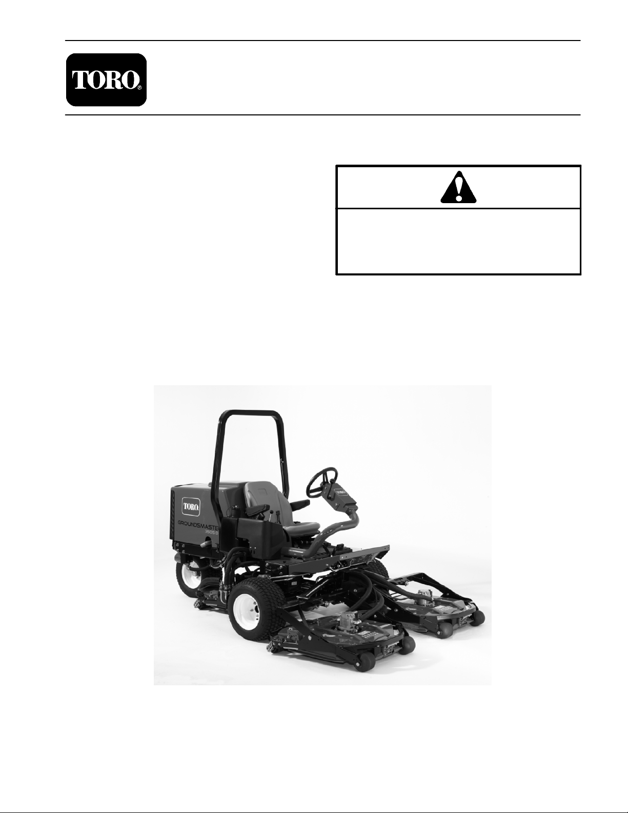
Groundsmaster
Preface
The purpose of this publication is to provide the service
technician with information for troubleshooting, testing,
and repair of major systems and components on the
Groundsmaster 3505--D.
REFER TO THE OPERATOR’S MANUAL FOR OPERATING, MAINTENANCE AND ADJUSTMENT
INSTRUCTIONS. For reference, insert a copy of the
Operator’s Manual and Parts Catalog for your machine
into Chapter 2 of this service manual. Additional copies
of the Operator’s Manual and Parts Catalog are available on the internet at www.Toro.com.
The Toro Company reserves the right to change product
specifications or this publication without notice.
R
3505--D
This safety symbol means DANGER, WARNING
or CAUTION, PERSONAL SAFETY INSTRUCTION. When you see this symbol, carefully read
the instructions that follow. Failure to obey the
instructions may result in personal injury.
NOTE: A NOTE will give general information about the
correct operation, maintenance, service, testing or
repair of the machine.
IMPORTANT: The IMPORTANT notice will give important instructions which must be followed to prevent damage to systems or components on the
machine.
E The Toro Company -- 2005, 2007, 2009
Page 2

This page is intentionally blank.
Groundsmaster 3505--D
Page 3

Table Of Contents
Chapter 1 -- Safety
General Safety Instructions 1 -- 1..................
Jacking Instructions 1 -- 4.........................
Chapter 2 -- Product Records and Maintenance
Product Records 2 -- 1...........................
Maintenance 2 -- 1...............................
Equivalents and Conversions 2 -- 2................
Torque Specifications 2 -- 3.......................
Chapter 3 -- Kubota Diesel Engine
Introduction 3 -- 2................................
Specifications 3 -- 3..............................
Service and Repairs 3 -- 4........................
KUBOTA WORKSHOP MANUAL, DIESEL ENGINE,
05 SERIES
Chapter 4 -- Hydraulic System
Specifications 4 -- 2..............................
General Information 4 -- 3........................
Hydraulic Schematic 4 -- 7........................
Hydraulic Flow Diagrams 4 -- 8....................
Special Tools 4 -- 18.............................
Troubleshooting 4 -- 22...........................
Testing 4 - - 25...................................
Adjustments 4 -- 50..............................
Service and Repairs 4 -- 51.......................
ROSS TORQMOTOR
RIES SERVICE PROCEDURE
EATON MEDIUM DUTY PISTON PUMP REPAIR IN-
FORMATION MODEL 70160 VARIABLE DISPLACEMENT PISTON PUMP
SAUER/DANFOSS STEERING UNIT TYPE OSPM
SERVICE MANUAL
TM
MG, MF, ME, AND MJ SE-
Chapter 5 -- Electrical System
Electrical Schematics and Diagrams 5 -- 1..........
Special Tools 5 -- 2..............................
Troubleshooting 5 -- 4............................
Electrical System Quick Checks 5 -- 7..............
Component Testing 5 -- 9.........................
Service and Repairs 5 -- 22.......................
Chapter 6 -- Chassis
Specifications 6 -- 2..............................
Special Tools 6 -- 3..............................
Adjustments 6 -- 4...............................
Service and Repairs 6 -- 6........................
Chapter 7 -- Cutting Units
Specifications 7 -- 2..............................
Special Tools 7 -- 3..............................
Troubleshooting 7 -- 4............................
Adjustments 7 -- 5...............................
Service and Repairs 7 -- 6........................
Chapter 8 -- Electrical Diagrams
Electrical Schematic 8 -- 3........................
Circuit Diagrams 8 -- 4...........................
Wire Harness Drawings 8 -- 8.....................
SafetyProduct Records
Kubota
Hydraulic
Electrical
ChassisCutting
and Maintenance
Diesel Engine
System
System
Groundsmaster 3505--D
Electrical
Units
Diagrams
Page 4

This page is intentionally blank.
Groundsmaster 3505--D
Page 5
Table of Contents
GENERAL SAFETY INSTRUCTIONS 1............
Supervisor’s Responsibilities 1.................
Before Operating 1............................
While Operating 2.............................
Maintenance and Service 3....................
JACKING INSTRUCTIONS 4.....................
General Safety Instructions
The GROUNDSMASTER 3505--D was tested and certified by TORO for compliance with existing standards
and specifications as identified in the Operator’s Manual. Although hazard control and accident prevention are
dependent partially upon the design and configuration
of the machine, these factors are also dependent upon
the awareness, concern and proper training of the personnel involved in the operation, transport, maintenance and storage of the machine. Improper use or
maintenance by the operator or owner of the machine
can result in injury. To reduce the potential for any injury,
comply with the following safety instructions.
Chapter 1
Safety
Safety
WARNING
To reduce the potential for injury or death,
comply with the following safety instructions.
Supervisor’s Responsibilities
1. Make sure operators are thoroughly trained and familiar with the Operator’s Manual, Operator’s Video and
all the operating and safety decals on the machine.
2. Be sure to establish your own special procedures
and work rules for unusual operating conditions (e.g.
slopes too steep for machine operation). Survey mow-
ing site completely to determine which hills can be
Before Operating
1. Read and understand the contents of the Operator’s
Manual before starting and operating the machine. Become familiar with the controls and know how to stop the
machine and engine quickly. Copies of the Operator’s
Manual are available on the internet at www.Toro.com.
2. Keep all shields, safety devices and decals in place.
If a shield, safety device or decal is defective, illegible or
damaged, repair or replace it before operating the machine. Also tighten any loose nuts, bolts or screws to ensure machine is in safe operating condition.
operated on safely. When performing this site survey,
always use common sense and take into consideration
the turf condition and the rollover risk. To perform a site
survey, follow the procedure outlined in the Traction Unit
Operator’s Manual. THE MAXIMUM SIDE HILL
ANGLE SHOULD NOT BE GREATER THAN 15 DEGREES.
3. Assure that operator’s presence controls, safety
switches and shields are attached and functioning properly. Do not operate the machine unless these items are
functioning properly.
Groundsmaster 3505--D Page 1 -- 1 Safety
Rev. B
Page 6

4. Since fuel is highly flammable, handle it carefully:
A. Store fuel in containers specifically designed for
this purpose.
B. Do not remove machine fuel tank cap while engine is hot or running.
C. Do not smoke while handling fuel.
While Operating
D. Fill fuel tank outdoors and only to within an inch of
the top of the tank, not the filler neck. Do not overfill.
E. Replace fuel tank and fuel container caps securely after refueling machine.
F. If fuel is spilled, do not attempt to start the engine
but move the machine away from the area of the spillage. Avoid creating any source of ignition until fuel
vapors have dissipated. Clean up any spilled fuel.
1. Sit on the seat when starting and operating the machine.
2. Before starting the engine:
A. Engage the parking brake.
B. Make sure traction pedal is in neutral and the
P.T.O. switch is OFF (disengaged).
C. After engine is started, release parking brake and
keep foot off traction pedal. Machine must not move.
If movement is evident, the traction pedal linkage is
adjusted incorrectly; therefore, shut engine off and
adjust traction pedal linkage until machine does not
move when traction pedal is released (see Traction
Unit Operator’s Manual).
3. Do not run engine in a confined area without adequate ventilation. Exhaust fumes are hazardous and
could possibly be deadly.
4. The slope angle at which the machine will tip is dependent on many factors. Among these are mowing
conditions such as wet or undulating turf, speed (especially in turns), tire pressure and operator experience. At
side hill angles of 10 degrees or less, the risk of a rollover
is low. As the slope angle increases to a recommended
maximum limit of 15 degrees, the risk of a rollover increases to a moderate level. DO NOT EXCEED A 15
DEGREE SIDE HILL ANGLE BECAUSE THE RISK OF
A ROLLOVER AND SERIOUS INJURY OR DEATH IS
VERY HIGH.
5. Do not touch engine, radiator or exhaust system
while engine is running or soon after it is stopped. These
areas could be hot enough to cause burns.
6. Before getting off the seat:
A. Ensure that traction pedal is in neutral.
B. Lower and disengage cutting decks and wait for
all movement to stop.
C. Set parking brake.
D. Stop engine and remove key from ignition switch.
7. Anytime the machine is parked (short or long term),
the cutting decks should be lowered to the ground. This
relieves pressure from the lift circuit and eliminates the
risk of a cutting deck accidentally lowering to the ground.
8. Do not park on slopes unless wheels are chocked or
blocked.
Groundsmaster 3505--DPage 1 -- 2Safety
Page 7

Maintenance and Service
1. Before servicing or making adjustments, lower cutting decks, stop engine, set parking brake and remove
key from the switch.
2. Make sure machine is in safe operating condition by
keeping all nuts, bolts and screws tight.
3. Never store the machine or fuel container inside
where there is an open flame, such as near a water heater or furnace.
4. Make sure all hydraulic line c onnectors are tight, and
all hydraulic hoses and lines are in good condition before applying pressure to the hydraulic system.
5. Keep body and hands away from pin hole leaks in hydraulic lines that eject high pressure hydraulic fluid. Use
cardboard or paper to find hydraulic leaks. Hydraulic
fluid escaping under pressure can penetrate skin and
cause injury. Fluid accidentally injected into the skin
must be surgically removed within a few hours by a doctor familiar with this form of injury or gangrene may result.
6. Before disconnecting or performing any work on the
hydraulic system, all pressure in the system must be relieved by lowering the cutting decks to the ground, stopping the engine and then using all of the hydraulic
controls (depressing the traction pedal, turning the
steering wheel in both directions and energizing the
deck solenoid with the engine not running).
7. If major repairs are ever needed or assistance is desired, contact an Authorized Toro Distributor.
8. Use care when checking or servicing the cutting
deck. Wear gloves and use caution when servicing it.
9. To reduce potential fire hazard, keep engine area
free of excessive grease, grass, leaves and dirt. Clean
protective screen on machine frequently.
10.If engine must be running to perform maintenance or
to make an adjustment, keep hands, feet, clothing and
other parts of the body away from the cutting decks and
other moving parts. Keep bystanders away.
11. Do not overspeed the engine by changing governor
setting. To assure safety and accuracy,check maximum
engine speed with a tachometer.
12.Shut engine off before checking or adding oil to the
crankcase.
13.Disconnect battery before servicing the machine.
Disconnect negative battery cable first and positive
cable last. If battery voltage is required for troubleshooting or test procedures, temporarily connect the battery.
Reconnect positive cable first and negative cable last.
14.Battery acid is poisonous and can cause burns.
Avoid contact with skin, eyes and clothing. Protect your
face, eyes and clothing when working with a battery.
15.Battery gases can explode. Keep cigarettes, sparks
and flames away from the battery.
16.If welding on the machine is necessary, disconnect
the negative battery cable to prevent electrical system
damage.
17.At the time of manufacture, the machine conformed
to the safety standards for riding mowers. To assure optimum performance and continued safety certification of
the machine, use genuine Toro replacement parts and
accessories. Replacement parts and accessories made
by other manufacturers may result in non-conformance
with the safety standards, and the warranty may be
voided.
18.When changing attachments, tires or performing
other service, use correct blocks, hoists and jacks.
Make sure machine is parked on a solid level floor such
as a concrete floor. Prior to raising the machine, remove
any attachments that may interfere with the safe and
proper raising of the machine. Always chock or block
wheels. Use jack stands or solid wood blocks to support
the raised machine. If the machine is not properly supported by blocks or jack stands, the machine may move
or fall, which may result in personal injury (see Jacking
Instructions in this chapter).
Safety
Groundsmaster 3505--D Page 1 -- 3 Safety
Page 8
Jacking Instructions
CAUTION
When changing attachments, tires or performing
other service, use correct blocks, hoists and
jacks. Make sure machine is parked on a solid level floor such as a concrete floor. Prior to raising
machine, remove any attachments thatmay interfere with the safe and proper raising of the machine. Always chock or block wheels. Use jack
stands or solid wood blocks to support the raised
machine. If the machine is not properly supported by blocks or jack stands, the machine may
move or fall, which may result in personal injury.
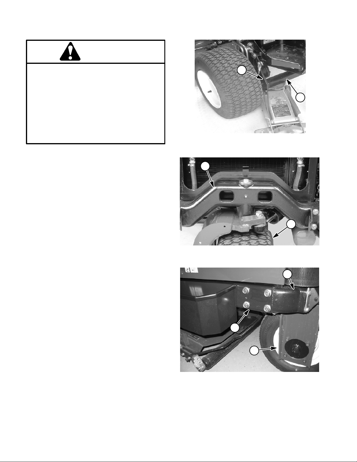
Jacking the Front End
1. If the front wheel motor is to be removed, position
jack securely under the square tube of the lower frame
as closely to the side plate as possible (Fig. 1).
2. If the front tire is to be removed, position the jack securely under the front wheel motor.
3. Use jack stands or hardwood blocks under the
square tube or wheel motors to support the machine.
Jacking the Rear End
2
1
Figure 1
1. Square tube 2. Side plate
2
1
1. The preferred method for removing the rear fork or
the rear wheel is to lift the rear end of the machine from
above:
A. Secure a chain fall or hoist to the rear casting (Fig
2).
B. Chock both front tires. Lift rear tire off the ground.
C. Use jack stands or hardwood blocks under the
frame to support the machine (Fig. 3).
2. If the rear of the machine cannot be lifted from above:
A. Chock both front tires.
IMPORTANT: Make sure jack is as close to the
rear fork as possible when jacking the machine.
B. Place jack s ecurely under the rear casting as
close to the fork as possible (Fig. 3). Jack rear tire off
the g round.
C. Use jack stands or blocks under the frame to support the machine.
Figure 2
1. Rear tire 2. Rear casting
1
3
Figure 3
1. Frame
2. Rear casting
3. Rear fork
2
Groundsmaster 3505--DPage 1 -- 4Safety
Page 9

Product Records and Maintenance
Table of Contents
Chapter 2
PRODUCT RECORDS 1.........................
MAINTENANCE 1...............................
EQUIVALENTS AND CONVERSIONS 2...........
Decimal and Millimeter Equivalents 2............
U.S. to Metric Conversions 2...................
TORQUE SPECIFICATIONS 3....................
Fastener Identification 3.......................
Product Records
Insert a copy of the Operator’s Manual and Parts Catalog for your Groundsmaster 3505--D at the end of this
chapter. Additionally, if any optional equipment or accessories have been installed to your Groundsmaster,
insert the Installation Instructions, Operator’s Manuals
and Parts Catalogs for those options at the end of this
chapter.
Maintenance
Maintenance procedures and recommended service intervals for the Groundsmaster 3505--D are covered in
the Operator’s Manual. Refer to that publication when
performing regular equipment maintenance.
Standard Torque for Dry, Zinc Plated and Steel Fas-
teners (Inch Series) 4........................
Standard Torque for Dry, Zinc Plated and Steel Fas-
teners (Metric Fasteners) 5...................
Other Torque Specifications 6..................
Conversion Factors 6..........................
Product Records
and Maintenance
Groundsmaster 3505--D Page 2 -- 1 Product Records and Maintenance
Page 10
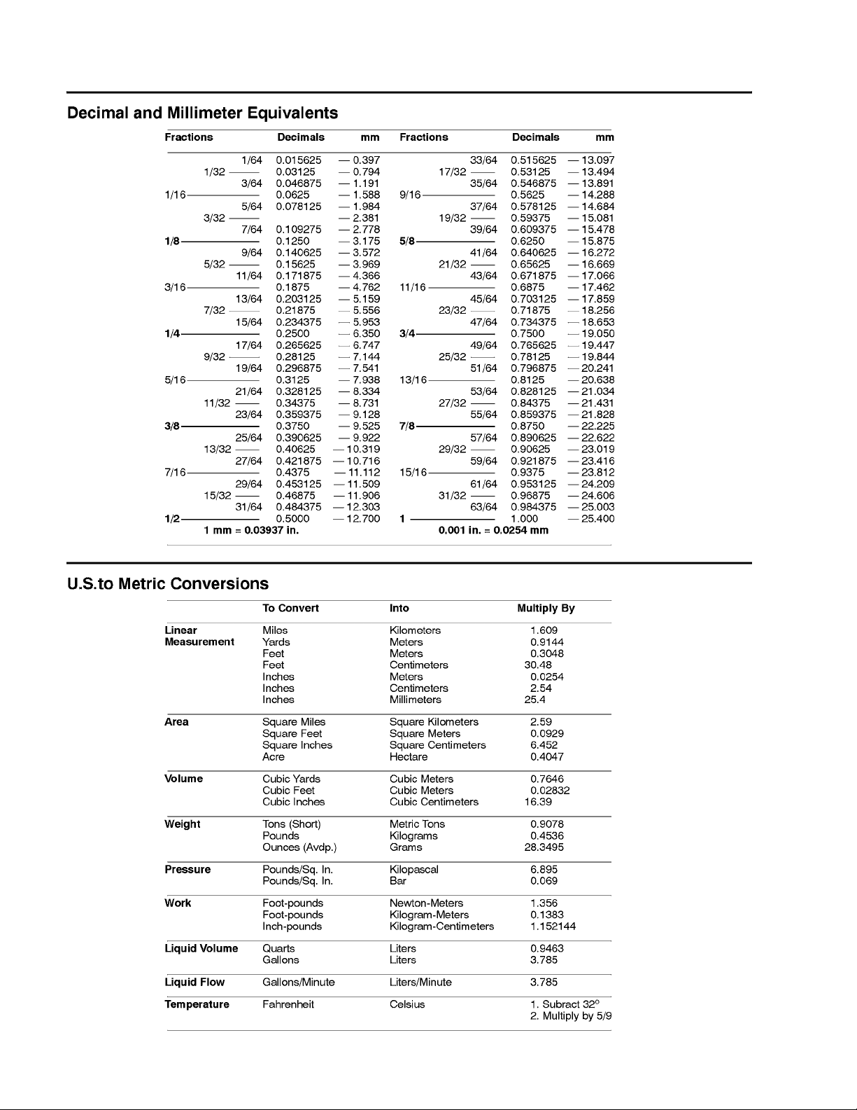
Equivalents and Conversions
0.09375
Rev. A
Groundsmaster 3505--DPage 2 -- 2Product Records and Maintenance
Page 11
Torque Specifications
Recommended fastener torque values are listed in the
following tables. For critical applications, as determined
by Toro, either the recommended torque or a torque that
is unique to the application is clearly identified and specified in this Service Manual.
These Torque Specifications for the installation and
tightening of fasteners shall apply to all fasteners which
do not have a s pecific requirement identified in this Service Manual. The following factors should be considered
when applying torque: cleanliness of the fastener, use
of a thread sealant (e.g. Loctite), degree of lubrication
on the fastener, presence of a prevailing torque feature
(e.g. Nylock nut), hardness of the surface underneath
the fastener’shead or similar condition which affects the
installation.
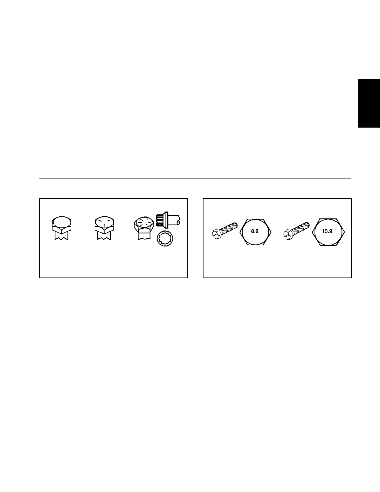
Fastener Identification
As noted in the following tables, torque values should be
reduced by 25% for lubricated fasteners to achieve
the similar stress as a dry fastener. Torque values may
also have to be reduced when the fastener is threaded
into aluminum or brass. The specific torque value
should be determined based on the aluminum or brass
material strength, fastener size, length of thread engagement, etc.
The standard method of verifying torque shall be performed by marking a line on the fastener (head or nut)
and mating part, then back off fastener 1/4 of a turn.
Measure the torque required to tighten the fastener until
the lines match up.
Product Records
and Maintenance
Grade 1 Grade 5 Grade 8
Inch Series Bolts and Screws
Figure 1
Class 8.8 Class 10.9
Metric Bolts and Screws
Figure 2
Groundsmaster 3505--D Page 2 -- 3 Product Records and Maintenance
Page 12
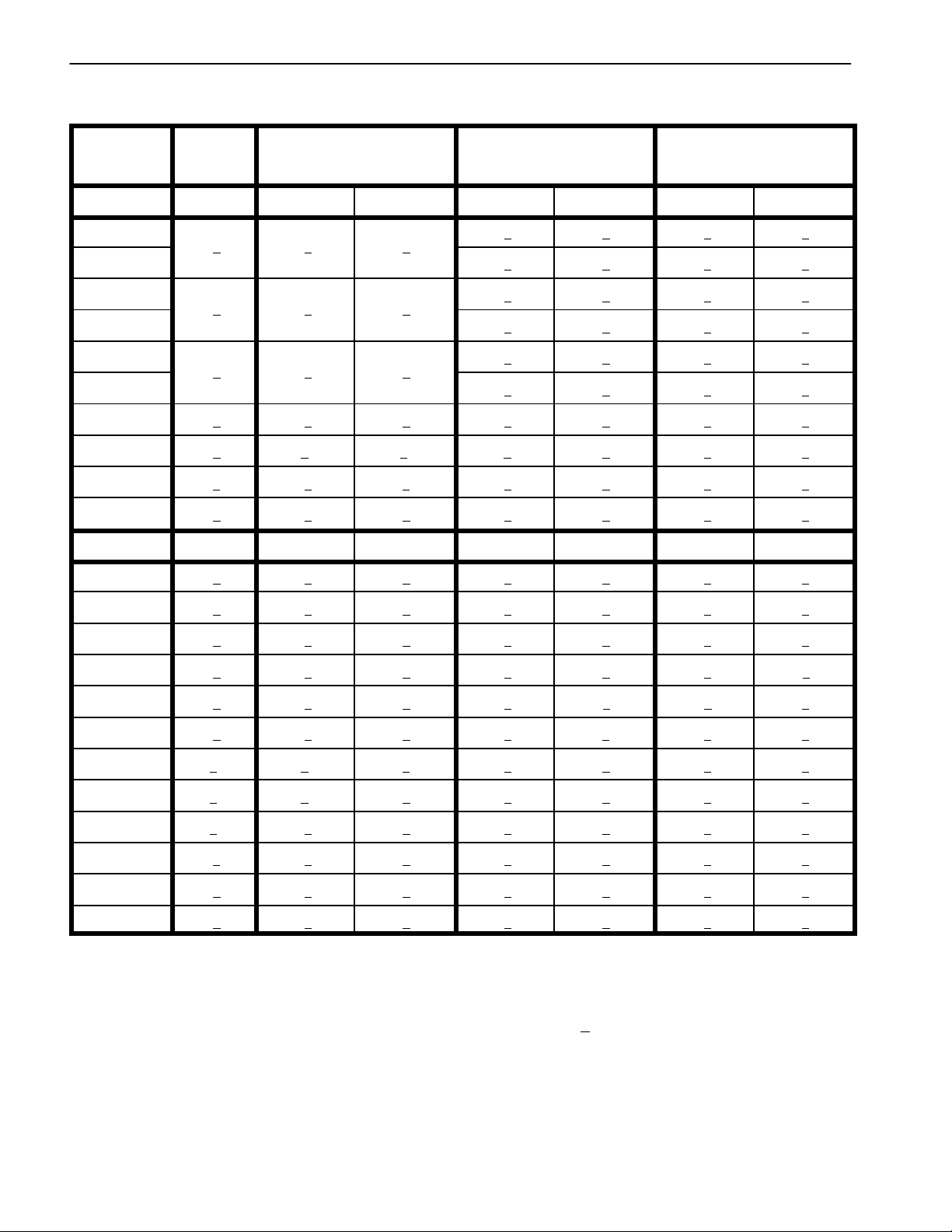
Standard Torque for Dry, Zinc Plated and Steel Fasteners (Inch Series)
Thread Size
# 6 -- 32 UNC
# 6 -- 40 UNF
# 8 -- 32 UNC
# 8 -- 36 UNF
#10--24UNC
#10--32UNF
1/4 -- 20 UNC 48 + 7 53 + 7 599 + 79 100 + 10 1130 + 11 3 140 + 15 1582 + 169
1/4 -- 28 UNF 53 + 7 65 + 10 734 + 113 115 + 12 1299 + 136 160 + 17 1808 + 192
5/16 -- 18 UNC 115 + 15 105 + 15 1186 + 169 200 + 25 2260 + 282 300 + 30 3390 + 339
5/16 -- 24 UNF 138 + 17 128 + 17 1446 + 192 225 + 25 2542 + 282 325 + 33 3672 + 373
3/8 -- 16 UNC 16 + 2 16 + 2 22 + 3 30 + 3 41 + 4 43 + 5 58 + 7
Grade 1, 5 &
8withThin
Height Nuts
in--lb in--lb N--cm in --lb N--cm in --lb N--cm
10 + 2 13 + 2 147 + 23
13 + 2 25 + 5 282 + 30
18 + 2 30 + 5 339 + 56
ft--lb ft--lb N--m ft--lb N--m ft--lb N-- m
SAE Grade 1 Bolts, Screws, Studs &
Sems with Regular Height Nuts
(SAE J995 Grade 2 or Stronger Nuts)
SAE Grade 5 Bolts, Screws, Studs &
Sems with Regular Height Nuts
(SAE J995 Grade 2 or Stronger Nuts)
15 + 2 169 + 23 23 + 3 262 + 34
17 + 2 192 + 23 25 + 3 282 + 34
29 + 3 328 + 34 41 + 5 463 + 56
31 + 4 350 + 45 43 + 5 486 + 56
42 + 5 475 + 56 60 + 6 678 + 68
48 + 5 542 + 56 68 + 7 768 + 79
SAE Grade 8 Bolts, Screws, Studs &
Sems with Regular Height Nuts
(SAE J995 Grade 5 or Stronger Nuts)
3/8 -- 24 UNF 17 + 2 18 + 2 24 + 3 35 + 4 47 + 5 50 + 6 68 + 8
7/16 -- 14 UNC 27 + 3 27 + 3 37 + 4 50 + 5 68 + 7 70 + 7 95 + 9
7/16 -- 20 UNF 29 + 3 29 + 3 39 + 4 55 + 6 75 + 8 77 + 8 104 + 11
1/2 -- 13 UNC 30 + 3 48 + 7 65 + 9 75 + 8 102 + 11 105 + 11 142 + 15
1/2 -- 20 UNF 32 + 4 53 + 7 72 + 9 85 + 9 115 + 12 120 + 12 163 + 16
5/8 -- 11 UNC 65 + 10 88 + 12 119 + 16 150 + 15 203 + 20 210 + 21 285 + 28
5/8 -- 18 UNF 75 + 10 95 + 15 129 + 20 170 + 18 230 + 24 240 + 24 325 + 33
3/4 -- 10 UNC 93 + 12 140 + 20 190 + 27 265 + 27 359 + 37 375 + 38 508 + 52
3/4 -- 16 UNF 115 + 15 165 + 25 224 + 34 300 + 30 407 + 41 420 + 43 569 + 58
7/8 -- 9 UNC 140 + 20 225 + 25 305 + 34 430 + 45 583 + 61 600 + 60 813 + 81
7/8 -- 14 UNF 155 + 25 260 + 30 353 + 41 475 + 48 644 + 65 667 + 66 904 + 89
NOTE: Torque values may have to be reduced when
installing fasteners into threaded aluminum or brass.
The specific torque value should be determined based
on the fastener size, the aluminum or base material
strength, length of thread engagement, etc.
NOTE: The nominal torque values listed above for
Grade 5 and 8 fasteners are based on 75% of the minimum proof load specified in SAE J429. The tolerance is
approximately +
10% of the nominal torque value. Thin
height nuts include jam nuts.
NOTE: Reduce torque values listed in the table above
by 25% for lubricated fasteners. Lubricated fasteners
are defined as threads coated with a lubricant such as
engine oil or thread sealant such as Loctite.
Groundsmaster 3505--DPage 2 -- 4Product Records and Maintenance
Rev. B
Page 13
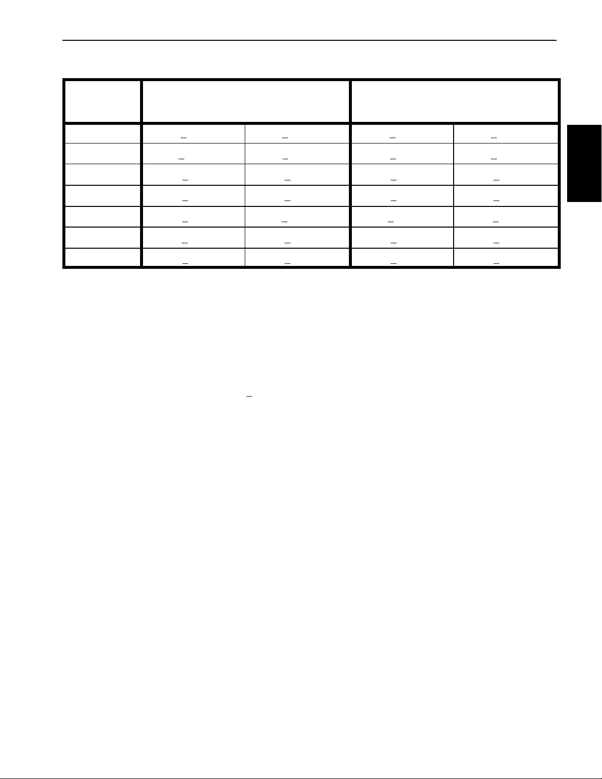
Standard Torque for Dry, Zinc Plated and Steel Fasteners (Metric Fasteners)
Class 8.8 Bolts, Screws and Studs with
Thread Size Regular Height Nuts
(Class 8 or Stronger Nuts)
M5 X 0.8 57 + 6in--lb 644 + 68 N--cm 78 + 8in--lb 881 + 90 N--cm
M6 X 1.0 96 + 10 in--lb 1085 + 11 3 N - -cm 133 + 14 in--lb 1503 + 158 N--cm
M8 X 1.25 19 + 2ft--lb 26 + 3N--m 28 + 3ft--lb 38 + 4N--m
M10 X 1.5 38 + 4ft--lb 52 + 5N--m 54 + 6ft--lb 73 + 8N--m
M12 X 1.75 66 + 7ft--lb 90 + 10 N--m 93 + 10 ft--lb 126 + 14 N--m
M16 X 2.0 166 + 17 ft--lb 225 + 23 N--m 229 + 23 ft--lb 310 + 31 N--m
M20 X 2.5 325 + 33 ft--lb 440 + 45 N--m 450 + 46 ft--lb 610 + 62 N--m
NOTE: Torque values may have to be reduced when
installing fasteners into threaded aluminum or brass.
The specific torque value should be determined based
on the fastener size, the aluminum or base material
strength, length of thread engagement, etc.
NOTE: The nominal torque values listed above are
based on 75% of the minimum proof load specified in
SAE J1199.The tolerance is approximately +
nominal torque value.
10% of the
NOTE: Reduce torque values listed in the table above
by 25% for lubricated fasteners. Lubricated fasteners
are defined as threads coated with a lubricant such as
engine oil or thread sealant such as Loctite.
Class 10.9 Bolts, Screws and Studs with
Regular Height Nuts
(Class 10 or Stronger Nuts)
Product Records
and Maintenance
Groundsmaster 3505--D Page 2 -- 5 Product Records and Maintenance
Page 14
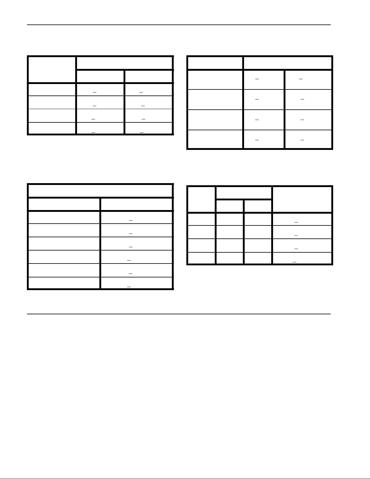
Other Torque Specifications
*
SAE Grade 8 Steel Set Screws
Recommended Torque
Thread Size
Square Head Hex Socket
1/4 -- 20 UNC 140 + 20 in--lb 73 + 12 in--lb
5/16 -- 18 UNC 215 + 35 in--lb 145 + 20 in--lb
3/8 -- 16 UNC 35 + 10 ft--lb 18 + 3ft--lb
1/2 -- 13 UNC 75 + 15 ft--lb 50 + 10 ft--lb
Thread Cutting Screws
(Zinc Plated Steel)
Type 1, Type 23 or Type F
Thread Size Baseline Torque*
No. 6 -- 32 UNC 20 + 5in--lb
Wheel Bolts and Lug Nuts
Thread Size
7/16 -- 20 UNF
Grade 5
1/2 -- 20 UNF
Grade 5
M12 X 1.25
Class 8.8
M12 X 1.5
Class 8.8
** For steel wheels and non--lubricated fasteners.
Thread Cutting Screws
(Zinc Plated Steel)
Thread
Size
No. 6 18 20 20 + 5in--lb
Threads per Inch
Type A Type B
Recommended Torque**
65 + 10 ft--lb 88 + 14 N--m
80 + 10 ft--lb 108 + 14 N--m
80 + 10 ft--lb 108 + 14 N--m
80 + 10 ft--lb 108 + 14 N--m
Baseline Torque
No. 8 -- 32 UNC 30 + 5in--lb
No. 10 -- 24 UNC 38 + 7in--lb
1/4 -- 20 UNC 85 + 15 in--lb
5/16 -- 18 UNC 110 + 20 in--lb
3/8 -- 16 UNC 200 + 100 in--lb
Conversion Factors
in--lb X 11.2985 = N--cm N-- cm X 0.08851 = in--lb
ft--lb X 1.3558 = N--m N--m X 0.7376 = ft--lb
No. 8 15 18 30 + 5in--lb
No. 10 12 16 38 + 7in--lb
No. 12 11 14 85 + 15 in--lb
* Hole size, material strength, material thickness & finish
must be considered when determining specific torque
values. All torque values are based on non--lubricated
fasteners.
Groundsmaster 3505--DPage 2 -- 6Product Records and Maintenance
Page 15

Table of Contents
INTRODUCTION 2..............................
SPECIFICATIONS 3.............................
SERVICE AND REPAIRS 4......................
Muffler and Air Cleaner Assembly 4.............
Muffler Removal 5...........................
Muffler Installation 5.........................
Air Cleaner Assembly Removal 6..............
Air Cleaner Assembly Installation 6............
Fuel System 8................................
Check Fuel Lines and Connections 9...........
Fuel Tank Removal 9........................
Drain and Clean Fuel Tank 9..................
Fuel Tank Installation 9.......................
Chapter 3
Kubota Diesel Engine
Radiator 10..................................
Removal 11.................................
Installation 11...............................
Engine 12....................................
Removal 12.................................
Installation 14...............................
KUBOTA WORKSHOP MANUAL, DIESEL ENGINE,
05 SERIES
Kubota
Diesel Engine
Groundsmaster 3505--D Page 3 -- 1 Kubota Diesel Engine
Page 16

Introduction
This Chapter gives information about specifications,
troubleshooting, testing and repair of the Kubota
D1105T diesel engine used in the Groundsmaster
3505--D. Refer to the Traction Unit Operator’s Manual
for engine maintenance information.
Most repairs and adjustments require tools which are
commonly available in many service shops. Special
tools are described in the Kubota Workshop Manual,
Diesel Engine, 05 Series included at the end of this
chapter. The use of some specialized test equipment is
explained. However, the cost of the test equipment and
the specialized nature of some repairs may dictate that
the work be done at an engine repair facility.
Service and repair parts for Kubota engines are supplied through your Authorized Toro Distributor. If no
parts list is available, be prepared to provide yourdistributor with the Toro equipment model and serial numbers
as well as the Kubota engine model and serial numbers.
Groundsmaster 3505--DPage 3 -- 2Kubota Diesel Engine
Page 17

Specifications
Item Description
Make / Designation Kubota D1105T, 3 Cylinder, Liquid Cooled,
Turbocharged, Diesel Engine
Horse Power 32 HP @ 2800 RPM
Bore mm (in.) 78.0 (3.07)
Stroke mm (in.) 78.4 (3.09)
Total Displacement cc (cu. in.) 1123 (68.53)
Firing Order 1--2--3
Combustion Chamber Spherical Type
Fuel No. 2 Diesel Fuel (ASTM D975)
Fuel Capacity liters (gallons) 41.6 (11)
Fuel Injection Pump Bosch MD Type Mini Pump
Governor Centrifugal Mechanical
Low Idle (no load) 1400 + 50 RPM
High Idle (no load) 3050 + 50 RPM
Kubota
Diesel Engine
Direction of Rotation Counterclockwise (Viewed from Flywheel)
Compression Ratio 23:1
Injection Nozzles Mini Nozzle (DNOPD)
Engine Oil See Traction Unit Operator’s Manual
Oil Pump Trochoid Type
Crankcase Oil Capacity liters (U.S. qt.) 3.8 (4.0) with Filter
Starter 12 VDC, 1.4 KW
Alternator/Regulator 12 VDC, 40 AMP
Dry Weight kilograms (U.S. lbs) 98.0 (216.0)
Coolant Capacity liters (U.S. qt.) 5.7 (6.0) with 0.9 (1.0) Reservoir
Groundsmaster 3505--D Page 3 -- 3 Kubota Diesel Engine
Page 18
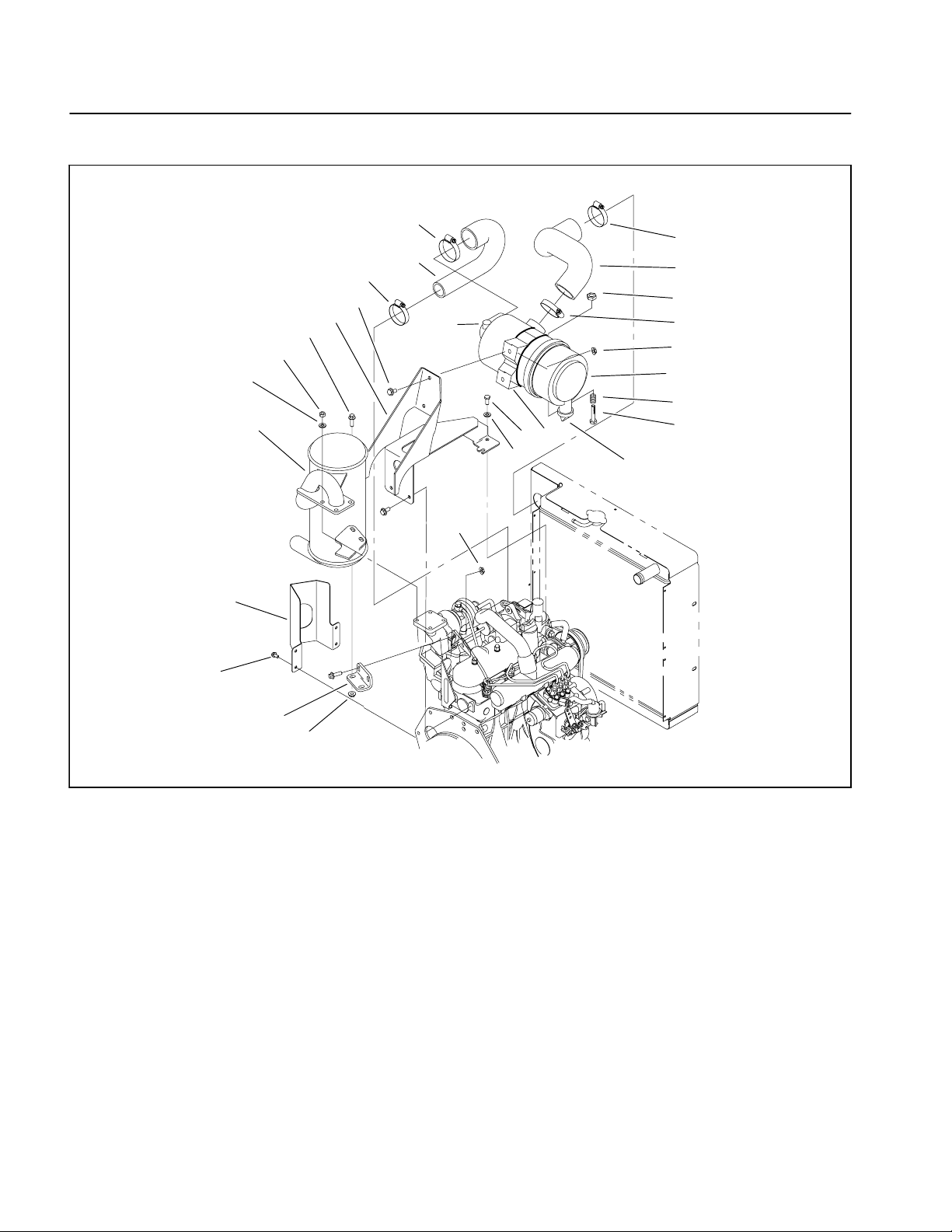
Service and Repairs
Muffler and Air Cleaner Assembly
18
16
17
12
14
11
10
2
8
4
7
19
1
20
18
3
9
21
18
13
6
5
23
22
3
1. Air inlet hose (upper)
2. Air inlet hose (lower)
3. Flange nut
4. Flange head screw
5. Flat washer
6. Cap screw
7. Air filter mount
8. Hose clamp
15
3
Figure 1
9. Air cleaner assembly
10. Flange head screw
11. Hex nut (4 used)
12. Lock washer (4 used)
13. Mounting band assembly
14. Muffler
15. Muffler bracket
16. Cap screw (4 used)
17. Exhaust guard (if used)
18. Hose clamp
19. Plug
20. Lock nut
21. Compression spring
22. Bolt
23. Vacuator valve
Groundsmaster 3505--DPage 3 -- 4Kubota Diesel Engine
Page 19
Muffler Removal (Fig. 1)
CAUTION
The muffler and exhaust pipe may be hot. To
avoid possible burns, allow the engine and exhaust system to cool before working on the muffler.
4
3
2
1. Park machine on a level surface, lower cutting units,
stop engine, engage parking brake and remove key
from the ignition switch.
2. Open hood to gain access to engine.
3. Remove exhaust guard (if equipped) from frame.
4. Remove both flange head nuts and screws securing
the muffler plate to the muffler bracket (Fig. 2).
5. Remove four hex nuts and lock washers from the exhaust manifold studs. Separate muffler flange from the
exhaust manifold. Remove muffler from the machine.
6. Remove exhaust gasket. Replace gasket if damaged or torn.
Muffler Installation (Fig. 1)
NOTE: Make sure muffler flange and exhaust manifold
sealing surfaces are free of debris or damage that may
prevent a tight seal.
1. Place exhaust gasket on the exhaust manifold.
1
1. Flange head nut
2. Flange head screw
Figure 2
3. Muffler plate
4. Muffler bracket
Kubota
Diesel Engine
IMPORTANT: Finger tighten all fasteners before securing the muffler plate to the muffler bracket so
there is no preload on the exhaust manifold.
2. Position muffler flange to the exhaust manifold with
four lock washers and hex nuts.
3. Position muffler plate to the muffler bracket with both
flange head screws and nuts (Fig. 2).
4. Tighten muffler flange hex nuts and then muffler
plate screws and nuts.
5. If equipped, install exhaust guard to frame.
6. Close and latch hood.
Groundsmaster 3505--D Page 3 -- 5 Kubota Diesel Engine
Page 20

Air Cleaner Assembly Removal (Fig. 1)
NOTE: See Traction Unit Operator’s Manual for air
cleaner maintenance procedures and intervals.
1. Park machine on a level surface, lower cutting units,
stop engine, engage parking brake and remove key
from the ignition switch. Unlatch and raise hood.
2. Remove air cleaner components as needed using
Figure 1 as a guide.
3. Check air cleaner body for damage that could cause
possible air leaks. Make sure that dust cup seals completely to the air cleaner body.
Air Cleaner Assembly Installation (Fig. 1)
IMPORTANT: Any leaks in the air filter system will
allow dirt into engine and will cause serious engine
damage. Make sure that all air cleaner components
are in good condition and are properly secured during assembly.
1. Assemble air cleaner system using Figure 1 as a
guide. Make sure that vacuator valve is pointed down after assembly (Fig. 3).
1
3
1. Latch
2. Dust cup
2
Figure 3
3. Vacuator valve
2. Close and latch hood.
Groundsmaster 3505--DPage 3 -- 6Kubota Diesel Engine
Page 21

This page is intentionally blank.
Kubota
Diesel Engine
Groundsmaster 3505--D Page 3 -- 7 Kubota Diesel Engine
Page 22
Fuel System
22
10
28
29
42
7
8
31
20
30
22
9
1
3
32
15
27
22
5
33
2
41
37
38
22
40
26
25
21
18
14
16
22
24
22
17
44
12
19
13
36
22
23
11
43
22
34
39
35
22
6
4
1. Cap screw (2 used)
2. Fuel tank
3. Fuel hose strap
4. Cap screw
5. Fuel cap
6. Tank support
7. Fuel gauge
8. Grommet
9. Connector fitting
10. Stand pipe
11. R--clamp
12. Barb fitting
13. Cap screw (2 used)
14. Flange hex nut (2 used)
15. Heat shield
Figure 4
16. Flat washer (2 used)
17. Tee fitting
18. Barb fitting
19. Barb fitting
20. Bushing
21. Spacer (2 used)
22. Hose clamp
23. Fuel prefilter
24. Fuel/water separator
25. Fuel fitting
26. Flange head screw (2 used)
27. Flange nut (2 used)
28. Seat support strap (2 used)
29. Foam (2 used)
30. Hex flange head screw (2 used)
31. Flat washer (2 used)
32. Fuel hose
33. Fuel hose
34. Fuel hose
35. Fuel hose
36. Fuel hose
37. Fuel hose
38. Fuel hose
39. R--clamp
40. Fuel pump
41. Spacer (2 used)
42. Cap screw (2 used)
43. Crossover fuel hose
44. Hose clamp
Groundsmaster 3505--DPage 3 -- 8Kubota Diesel Engine
Page 23
Fuel Tank Installation (Fig. 4)
DANGER
Because diesel fuel is highly flammable, use caution when storing or handling it. Do not smoke
while filling the fuel tank. Do not fill fuel tank
while engine is running or hot or when machine
is in an enclosed area. Always fill fuel tank outside and clean up any spilled diesel fuel before
starting the engine. Store fuel in a clean, safety-approved container and keep cap in place. Use
diesel fuel for the engine only; not for any other
purpose.
Check Fuel Lines and Connections
Check fuel lines and connections every 400 hours or
yearly, whichever comes first.
1. Park machine on a level surface, lower cutting units,
stop engine, engage parking brake and remove key
from the ignition switch. Unlatch and raise hood.
2. Check fuel lines for deterioration, damage, leaks or
loose connections. Replace hoses, clamps and connections as necessary.
1. Position fuel tank to the machine.
2. Connect both fuel hoses to the tank and secure with
hose clamps and fuel hose strap.
3. Connect seat switch to the electrical harness. Route
seat switch wire under seat support strap. Secure seat
support straps and seat to the frame (see Operator Seat
Installation in Chapter 6 -- Chassis).
4. Check for correct seat operation and also that seat
switch wires and connector are not pinched and do not
contact any moving parts.
5. Fill fuel tank (see Traction Unit Operator’s Manual).
3
4
1
5
Kubota
Diesel Engine
Fuel Tank Removal (Fig. 4)
1. Park machine on a level surface, lower cutting units,
stop engine, engage parking brake and remove key
from the ignition switch. Unlatch and raise hood.
2. Remove fuel from the tank into a suitable container.
Crossover fuel hose (item 44) removal may assist to
drain tank completely.
3. Remove seat and seat support straps from the frame
(see Operator Seat Removal in Chapter 6 -- Chassis).
Note location of spacers under front of seat support
straps. Disconnect seat switch from the electrical harness (Fig. 5).
4. Remove fuel hose strap and both fuel hoses from the
fuel tank. Pull tank from the machine (Fig. 5).
Drain and Clean Fuel Tank
Drain and clean the fuel tank every 2 years. Also, drain
and clean the fuel tank if the fuel system becomes contaminated or if the machine is to be stored for an extended period.
1. Seat support strap
2. Hex flange head screw
3. Electrical harness
2
Figure 5
4. Fuel hose strap
5. Fuel hose
1. Remove fuel tank from the machine (see Fuel Tank
Removal).
2. Flush fuel tank out with clean diesel fuel. Make sure
that tank is free of all contaminates and debris.
3. Install fuel tank to the machine (see Fuel Tank Installation).
Groundsmaster 3505--D Page 3 -- 9 Kubota Diesel Engine
Page 24
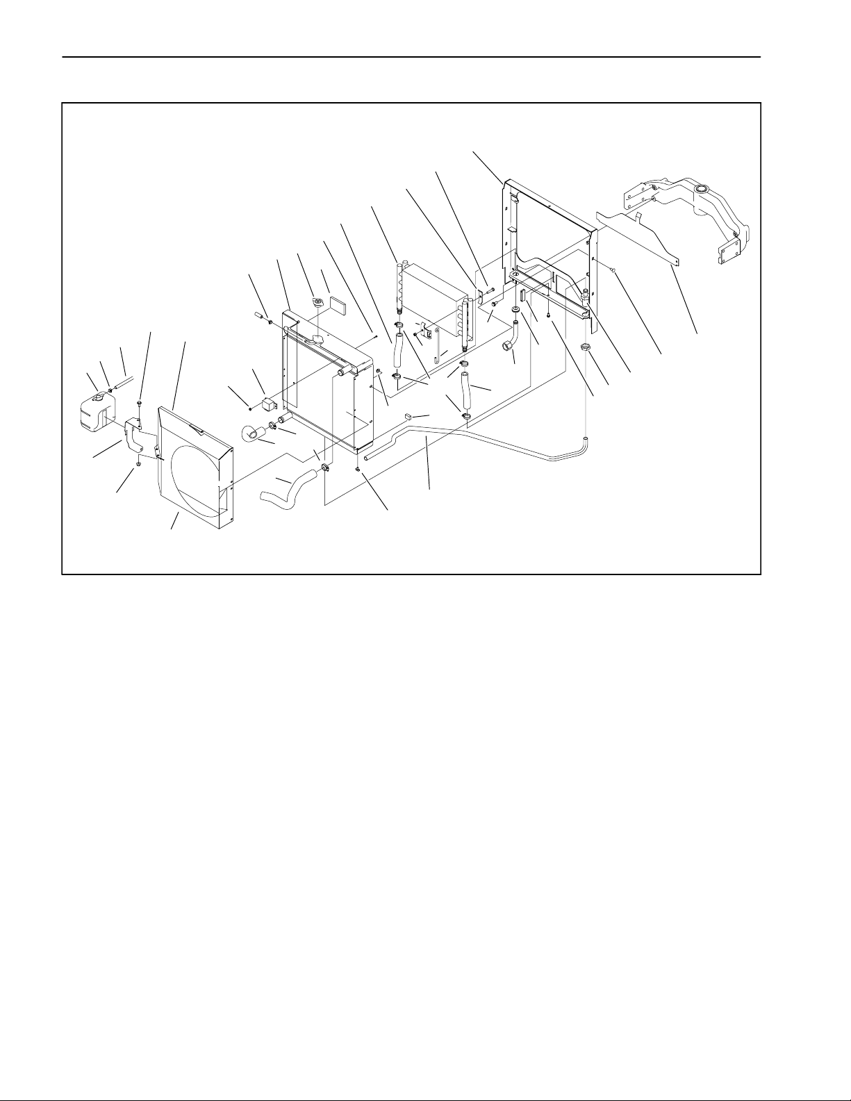
Radiator
10
18
17
22
28
34
11
5
9
30
13
31
9
32
14
38
1. Draincock valve
2. Flange head screw (11 used)
3. Flange nut (4 used)
4. Carriage bolt (4 used)
5. Radiator
6. Upper fan shroud
7. Lower fan shroud
8. Flange head screw (4 used)
9. Hose clamp
10. Radiator frame
11. Radiator cap
12. Radiator foam seal
13. Flange head screw (2 used)
6
35
7
33
23
24
16
3
25
1
Figure 6
14. Reservoir bracket
15. Wire form latch (2 used)
16. Oil cooler bracket (2 used)
17. Bracket clamp (2 used)
18. Screw (2 used)
19. Lock nut (2 used)
20. Radiator shield (lower)
21. Magnetic catch
22. Oil cooler
23. Radiator hose (upper)
24. Radiator hose (lower)
25. Hose clamp
26. Hydraulic tube
19
37
25
12
15
26
21
29
36
2
27. Hydraulic tube
28. Oil cooler hose
29. Grommet
30. Foam seal
31. Expansion tank hose
32. Expansion tank
33. Glow plug relay
34. Thread forming screw
35. Flange lock nut
36. Bulkhead nut
37. Tube assembly
38. Flange nut (2 used)
20
4
27
8
28
Groundsmaster 3505--DPage 3 -- 10Kubota Diesel Engine
Page 25
Removal (Fig. 6)
Installation (Fig. 6)
1. Park machine on a level surface, lower cutting units,
stop engine, engage parking brake and remove key
from the ignition switch.
2. Open and remove hood from the machine (see Traction Unit Operator’s Manual).
CAUTION
Do not open radiator cap or drain coolant if the
radiator or engine is hot. Pressurized, hot coolant can escape and cause burns. Ethylene--glycol antifreeze is poisonous. Dispose of coolant
properly or store it in a properly labeled container away from children and pets.
3. Place a suitable container under the radiator to collect the coolant. Open draincock valve and completely
drain the radiator.
4. Remove glow plug relay from the radiator assembly.
Position relay away from the radiator.
5. Disconnect following hoses from the radiator:
1. Remove any plugs placed in radiator and coolant
hose openings during the removal procedure.
2. Carefully position radiator to the radiator frame.
3. Secure radiator to the radiator frame with four (4)
carriage bolts and flange nuts. Secure top and bottom
of radiator to frame with flange head screws.
4. Secure lower and upper fan shrouds to the radiator
assembly with flange head screws.
5. Secure expansion tank bracket and tank to the top
fan shroud with flange head screws and flange nuts.
6. Connect following hoses to the radiator:
A. Upper radiator hose to the water pump.
B. Lower radiator hose to the engine block.
C. Coolant hose to the expansion tank.
D. Air hose to the air cleaner.
7. Secure glow plug relay to the radiator assembly.
Kubota
Diesel Engine
A. Upper radiator hose to the water pump.
B. Lower radiator hose to the engine block.
C. Coolant hose to the expansion tank.
D. Air hose to the air cleaner.
6. Remove expansion tank and bracket from the top fan
shroud.
7. Remove upper and lower fan shrouds from radiator
assembly.
8. Remove flange head screws securing the top and
bottom of the radiator frame to the radiator.Remove four
(4) carriage bolts and flange nuts securing the radiator
to the radiator frame.
9. Carefully pull radiator from the radiator frame.
10.Plug radiator and hose openings to prevent contamination.
8. Make sure radiator draincock valve is closed. Fill radiator with coolant (see Traction Unit Operator’s Manual).
9. Install hood to the machine (see Traction Unit Operator’s Manual). Close and latch hood.
Groundsmaster 3505--D Page 3 -- 11 Kubota Diesel Engine
Page 26
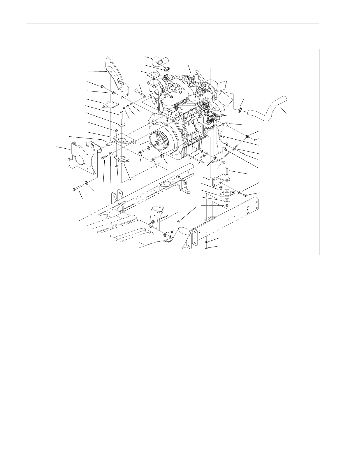
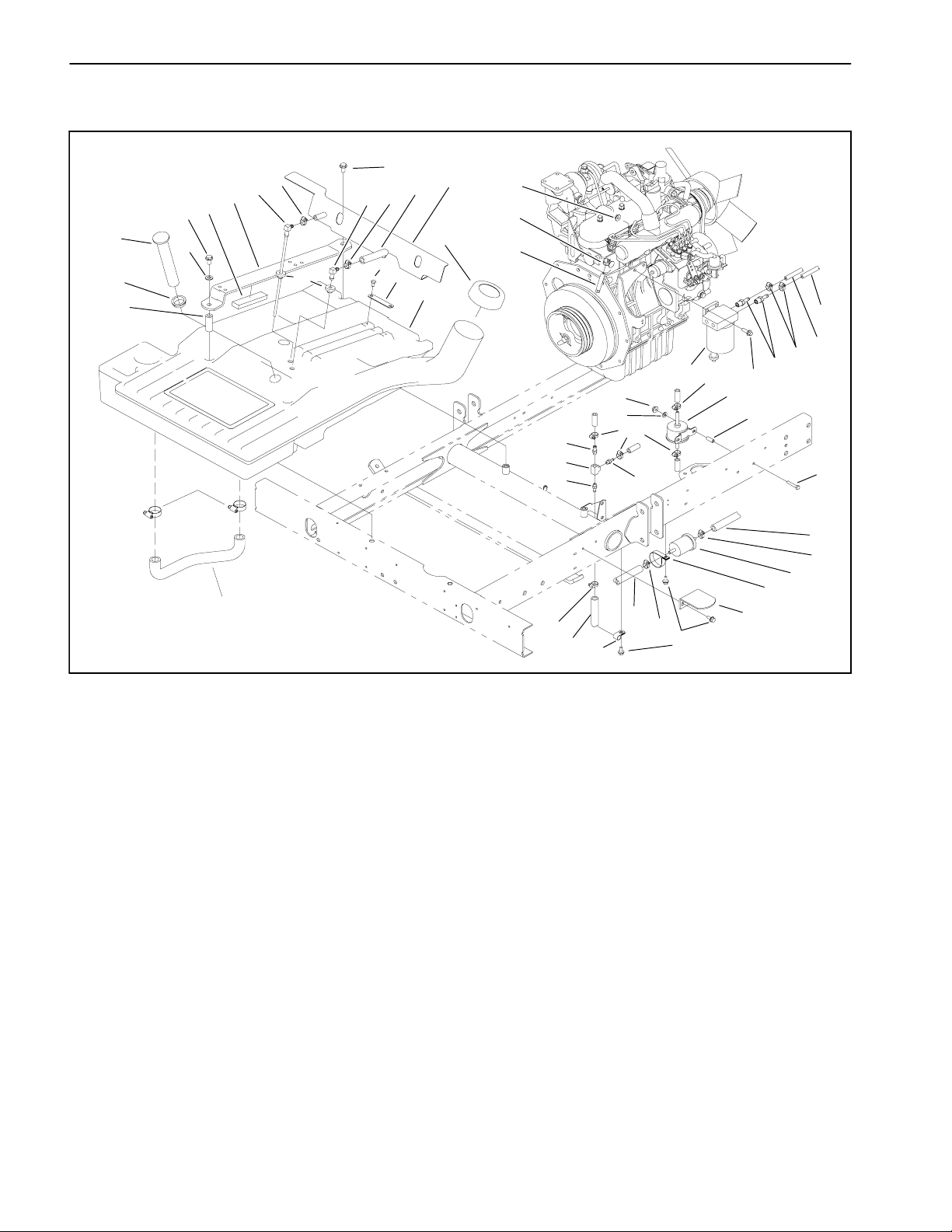
Engine
40
41
12
13
15
11
2
5
9
10
27
1
37
21
36
37
32
6
35
34
23
42
38
22
24
17
28
25
26
19
5
11
16
11
12
11
18
20
3
4
31
33
39
14
6
30
16
2
9
29
8
1. Kubota engine
2. Engine mount (2 used)
3. Engine mount
4. Flange nut (6 used)
5. Cap screw (3 used)
6. Flange head screw (6 used)
7. External lock washer
8. Lock nut (3 used)
9. Hardened washer (3 used)
10. Machine screw
11. Hardened washer (11 used)
12. Cap screw (5 used)
13. Engine mounting bracket (front)
14. Engine mounting bracket (LH)
15. Engine mounting bracket (RH)
16. Cap screw (4 used)
17. Pulley
18. Bolt (3 used)
19. Flange nut (2 used)
20. Flat washer (3 used)
21. Exhaust gasket
22. Throttle swivel
23. Lock nut
24. Slotted hex head screw
25. Throttle cable clamp
26. Cap screw
27. Radiator hose (lower)
28. Lock nut
Removal (Fig. 7)
1. Park machine on a level surface, lower cutting units,
stop engine, engage parking brake and remove key
from the ignition switch.
2. Open and remove hood from the machine (see Traction Unit Operator’s Manual). Slide operator seat all the
way forward.
3. Disconnect air hose from the air cleaner and radiator.
Remove air cleaner from the engine (see Air Cleaner
Assembly Removal in this section).
7
4
Figure 7
29. Lock washer
30. Flat washer
31. Flange head screw (2 used)
32. Flat washer
33. R--clamp
34. Lock washer
35. Hex nut
36. Wire harness
37. Hose clamp
38. Radiator hose (upper)
39. Wire harness ground
40. Pump mount plate
41. Spacer
42. Throttle support bracket
4. Disconnect both battery cables at the battery (see
Battery Service in Chapter 5 -- Electrical System).
5. Remove muffler from the exhaust manifold and muffler bracket (see Muffler Removal in this section).
6. Drain coolant from the radiator into a suitable container (see Radiator Removal in this section). Disconnect r adiator hoses from the water pump and engine
block.
Groundsmaster 3505--DPage 3 -- 12Kubota Diesel Engine
Page 27
7. Remove coolant expansion tank and bracket from
the upper fan shroud. Remove upper fan shroud from
the radiator (see Radiator Removal in this section).
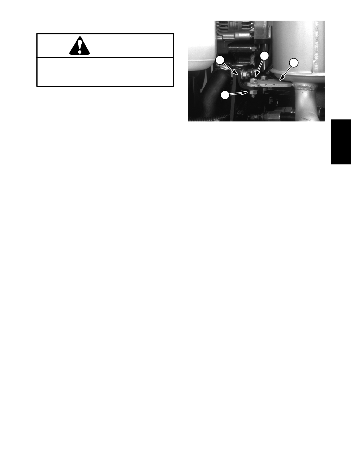
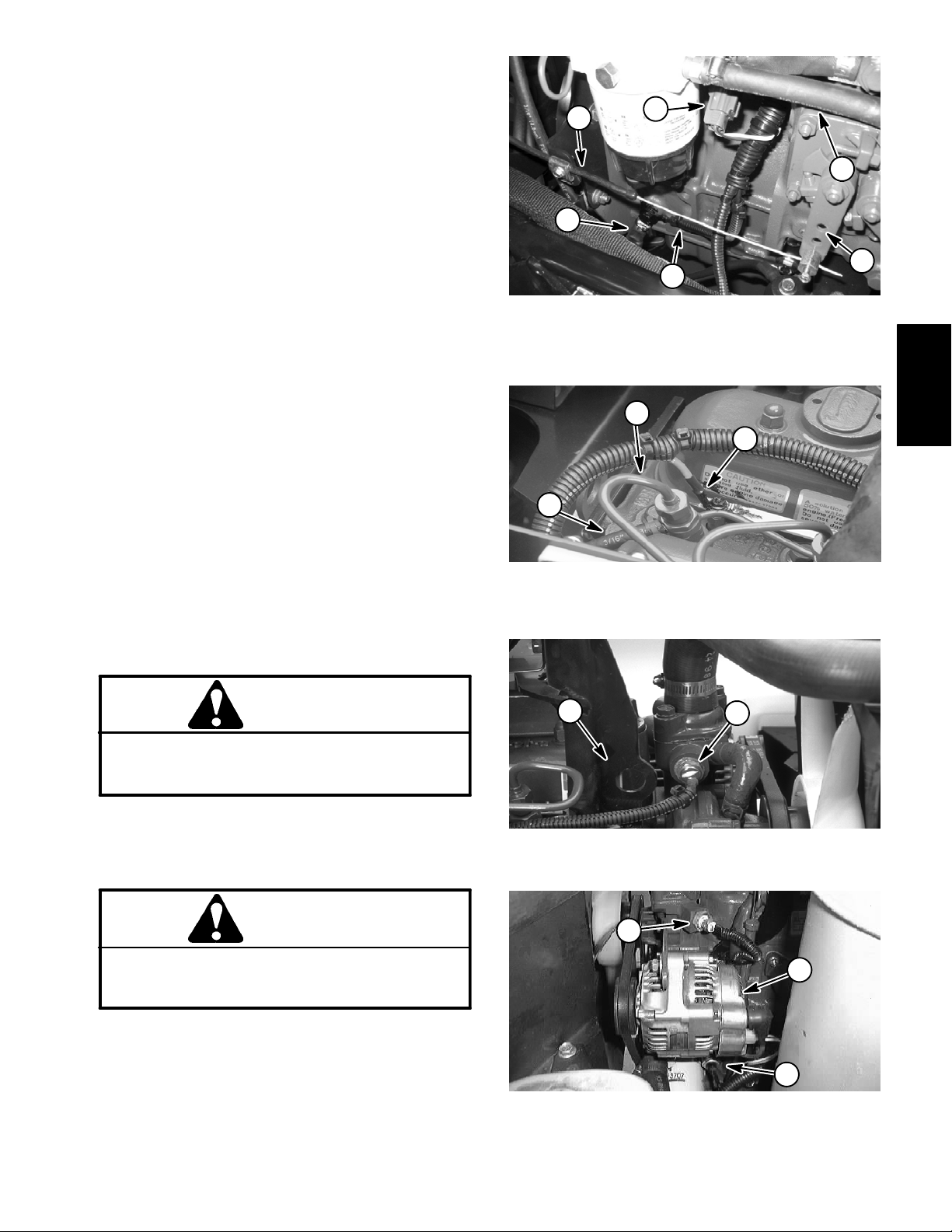
8. Disconnect electrical wires from engine:
4
3
A. Negative battery cable, wire harness ground and
fuel stop solenoid (Fig. 8).
B. Glow plug bus (Fig. 9).
C. High temperature w arning switch (Fig. 10).
D. High temperature shutdown switch, alternator
and oil pressure switch (Fig. 11).
9. Disconnect throttle cable from the throttle support
bracket and swivel on the speed control lever (Fig. 8).
10.Disconnect fuel hoses from the fuel/water separator
(Fig. 8). Position disconnected hose from fuel pump to
prevent fuel leakage.
11. Remove traction control cable from the neutral arm
assembly on the piston pump. Remove all hydraulic
hoses from the piston and gear pumps (see Piston
Pump Removal in the Service and Repairs section of
Chapter 4-- Hydraulic System).
12.Note location of cable ties securing the wire harness
to engine. Remove cable ties.
13.Attach a suitable lift or hoist to lift tabs on front (Fig.
10) and rear (on air filter mount) of engine.
1
1. Negative battery cable
2. Wire harness ground
3. Fuel stop solenoid
2
3
1. Glow plug wire
2. Rear injector nozzle
6
5
2
Figure 8
4. Throttle cable
5. Speed control lever
6. Fuel hose
Kubota
Diesel Engine
1
Figure 9
3. Fuel hose
CAUTION
Make sure lift or hoist can support the total
weight of the engine before removing the cap
screws from the engine and engine brackets.
14.Remove flange nuts (item 4), flange head screws
(item 6) and lock washer (item 7) s ecuring three engine
mounts to the engine mounting brackets.
CAUTION
One person should operate lift or hoist while a
second person guides the engine out of the machine.
IMPORTANT: Make sure not to damage the engine,
fuel hoses, hydraulic lines, electrical harness or
other parts while removing the engine.
15.Slowly remove engine from the machine.
2
1
Figure 10
1. Temp. warning switch 2. Front lift tab
1
3
Figure 11
1. Temp. shutdown switch
2. Alternator
3. Oil pressure switch
2
Groundsmaster 3505--D Page 3 -- 13 Kubota Diesel Engine
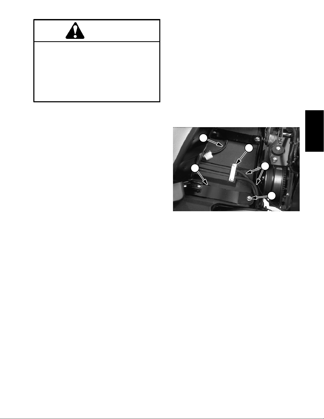
Page 28
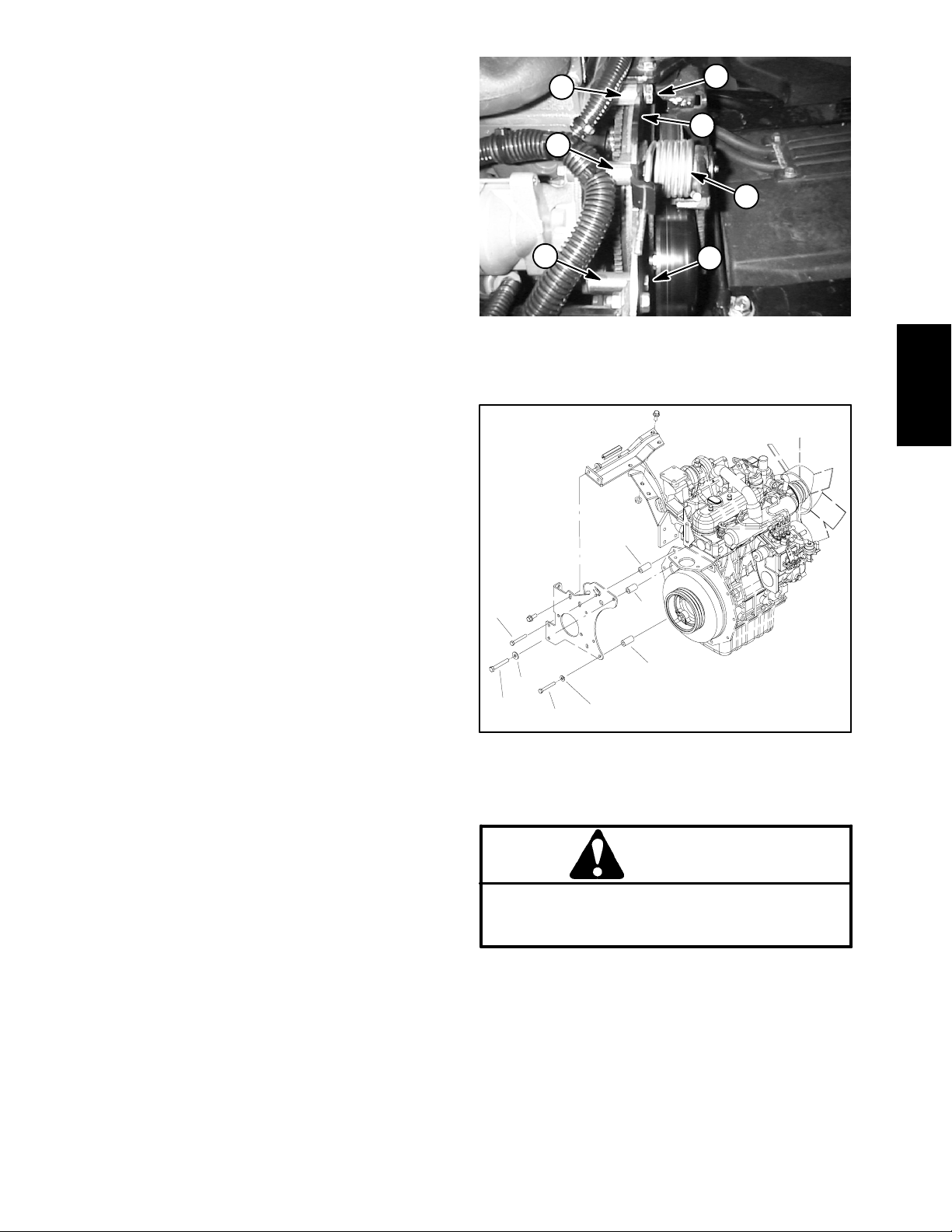
16.Separate hydrostat and pump mount plate from the
engine as follows:
2
1
A. Remove traction belt from the engine flywheel
and hydrostat pulleys (see Traction Unit Operator’s
Manual).
B. Support hydraulic pump assembly to prevent it
from falling during removal.
C. Remove five (5) cap screws, four (4) washers and
five (5) spacers securing the pump mount plate to the
engine (Fig. 12 and 13). Note location of spacers,
washers and cap screws during removal.
D. Remove four (4) cap screws (item 12) and hardened washers (item 11) securing the right engine
mounting bracket to the engine.
E. Remove hydrostat, pump mount plate and
mounting brackets from engine.
17.As necessary, remove engine mounts (item 3), front
engine mounting bracket (item 13), throttle support
bracket (item 42) and left engine mounting bracket (item
14).
Installation (Fig. 7)
6
6
1. Cap screw (10 mm)
2. Short spacer
3. Torsion spring
4
3
5
Figure 12
4. Pump mount plate
5. Cap screw (8 mm)
6. Long spacer (4 used)
Kubota
Diesel Engine
1
1. If removed, install engine mounts ( item 3), front engine mounting bracket (item 13), throttle support bracket
(item 42) and left engine mounting bracket (item 14).
Also, make sure that all switches and sensors are
installed on engine.
2. Install h ydrostat, pump mount plate and mounting
brackets to the engine as follows:
A. Position hydrostat, pump mount plate and mounting brackets to engine.
B. Secure right engine mounting bracket (with hydrostat attached) to the engine with four (4) hardened washers and cap screws.
NOTE: To prevent the torsion spring from binding,
do not install flat washer on cap screw near the
spring.
C. Using locations noted during engine removal, secure pump mount plate to the engine with five (5)
spacers, four (4) washers and five (5) cap screws
(Fig. 12 and 13).
D. Install traction belt to the engine flywheel and hydrostat pulleys (see Traction Unit Operator’s Manual).
3. Connect hoist or lift to the front and rear engine lift
tabs (Fig. 9 and 10).
3
4
5
3
6
1
2
Figure 13
1. Long spacer (4 used)
2. Flat washer (3 used)
3. 8 mm cap screw (4 used)
4. Hardened washer
5. 10 mm cap screw
6. Short spacer
CAUTION
One person should operate lift or hoist while a
second person guides the engine into the machine.
IMPORTANT: Make sure not to damage the engine,
fuel or hydraulic lines, electrical harness or other
parts while installing the engine.
4. Carefully lower engine into the machine.
5. Secure three (3) engine mounts to the engine mounting brackets with cap screws, washers and flange nuts.
Groundsmaster 3505--DPage 3 -- 14Kubota Diesel Engine
Page 29

6. Secure wire harness to the front lift tab and the engine with cable ties.
7. Install all hydraulic hoses to the piston and gear
pumps. Install traction control cable to the neutral arm
assembly on the piston pump (see Piston Pump Installation in Chapter 4-- Hydraulic System).
8. Connect fuel hose to the fuel/water separator (Fig. 8)
and front injector nozzle.
9. Install top fan shroud to the radiator. Install expansion tank and bracket to the top fan shroud (see Radiator
Installation in this section).
10.Connect electrical wires to engine:
12.Connect coolant hoses to the water pump and engine block. Close radiator drain cock valve. Fill radiator
with coolant (see Traction Unit Operator’s Manual).
13.Install muffler to the exhaust manifold and muffler
bracket (see Muffler Installation in this section).
14.Connect throttle cable to the support bracket and
swivel on the speed control lever (Fig. 8).
15.Connect both battery cables to the battery (see Battery Service in Chapter 5 -- Electrical system).
16.Install air cleaner to the engine (see Air Cleaner Assembly Installation in this section). Connect air hose to
air cleaner and radiator.
A. Negative battery cable and wire harness ground
(Fig. 8).
B. Glow plug bus (Fig. 9) and fuel stop solenoid.
C. High temperature w arning switch (Fig. 10).
D. High temperature shutdown switch, alternator
and oil pressure switch (Fig. 11).
11. Secure wire harness to engine with cable ties at locations noted during engine removal.
17.Adjust throttle cable (see Adjust Throttle Cable).
18.Bleed fuel system (see Traction Unit Operator’s
Manual).
19.Install hood to the machine (see TractionUnit Operator’s Manual). Close and latch hood.
20.Check hydraulic oil level (see Traction Unit Operator’s Manual). Adjust as needed.
21.Check traction drive for neutral (see Traction Unit
Operator’s Manual). Adjust as needed.
Groundsmaster 3505--D Page 3 -- 15 Kubota Diesel Engine
Page 30

This page is intentionally blank.
Groundsmaster 3505--DPage 3 -- 16Kubota Diesel Engine
Page 31

Table of Contents
Chapter 4
Hydraulic System
SPECIFICATIONS 2.............................
GENERAL INFORMATION 3.....................
Hydraulic Hoses 3.............................
Hydraulic Fitting Installation 3...................
Towing Traction Unit 5..........................
Relieving Hydraulic System Pressure 5...........
Traction Circuit (Closed Loop) Component Failure 6
HYDRAULIC SCHEMATIC 7.....................
HYDRAULIC FLOW DIAGRAMS 8................
Traction Circuits 8.............................
Cutting Unit Circuit 10..........................
Lift Circuit (Raise) 12...........................
Lift Circuit (Lower) 14..........................
Steering Circuit 16.............................
SPECIAL TOOLS 18............................
Hydraulic Pressure Test Kit 18...................
Hydraulic Tester (Pressure and Flow) 18..........
Hydraulic Test Fitting Kit 19.....................
Measuring Container 19........................
O--Ring Kit 20.................................
Wheel Hub Puller 20...........................
High Pressure Hydraulic Oil Filter 20.............
TROUBLESHOOTING 22........................
TESTING 25...................................
Traction Circuit Working Pressure Test 26.........
Charge Relief Valve Pressure Test 28............
Piston Pump (P3) Flow & Traction Relief
Pressure Test 30.............................
Wheel Motor Efficiency Test 32..................
Cutting Deck Circuit Pressure Test 34............
Manifold Relief Valve (R1) Pressure Test 36.......
Logic (Counterbalance) Valve (LC1)
Pressure Test 38.............................
Gear Pump (P1) Flow Test 40...................
Deck Motor Efficiency -- Case Drain Test 42.......
Steering and Lift Relief Pressure Test 44..........
Gear Pump (P2) Flow Test 46...................
Steering C ontrol Valve Test 48...................
ADJUSTMENTS 50.............................
Braking Valve Adjustment 50....................
SERVICE AND REPAIRS 51.....................
General Precautions for Removing and
Installing Hydraulic System Components 51.....
Check Hydraulic Lines and Hoses 51.............
Flush Hydraulic System 52......................
Charge Hydraulic System 53....................
Hydraulic Tank 54..............................
Oil C ooler 56..................................
Wheel Motors 58..............................
Wheel Motor Service 60........................
Cutting Deck Motors 62.........................
Cutting Deck Motor Service 64..................
Hydraulic Manifold 68
Hydraulic Manifold Service 70...................
Lift Control Valve 72............................
Lift Control Valve Service 74....................
Neutral Arm Assembly 78.......................
Piston Pump 80...............................
Piston Pump Service 84........................
Gear Pump 86................................
Gear Pump Service (Serial Number Below
260000400) 88...............................
Gear Pump Service (Serial Number Above
260000400) 91.1.............................
Steering Control Valve 92.......................
Steering Control Valve Service 94................
Front Lift Cylinder 96...........................
Rear Lift Cylinder 98...........................
Lift Cylinder Service 100........................
Steering Cylinder 102..........................
Steering Cylinder Service 104...................
ROSS TORQMOTOR
RIES SERVICE PROCEDURE
EATON MEDIUM DUTY PISTON PUMP REPAIR IN-
FORMATION MODEL 70160 VARIABLE DISPLACEMENT PISTON PUMP
SAUER/DANFOSS STEERING UNIT TYPE OSPM
SERVICE MANUAL
..........................
TM
MG, MF, ME AND MJ SE-
System
Hydraulic
Groundsmaster 3505--D Hydraulic SystemPage 4 -- 1
Rev. B
Page 32

Specifications
Item Description
Piston Pump (Hydrostat) (P3) Variable displacement piston pump
Charge Pressure 100 to 150 PSI (6.9 to 10.3 bar)
Traction Circuit Relief Pressure (Forward Only) 3000 PSI (207 bar)
Gear Pump (P1 and P2) Dual section, positive displacement, gear pump
Section P1 Displacement .946 in
Section P2 Displacement .31 in
Counterbalance Pressure (LC1) 250 PSI (17.2 bar)
Hydraulic Manifold Relief Pressure (R1) 3200 PSI (221 bar)
Cutting Unit Motor Gear motor
Cross--over Relief Pressure 1813 PSI (125 bar)
Wheel Motors Orbital rotor motor
Steering Control Valve Sauer Danfoss S teering Unit, Type OSPM
Implement (Steering and Lift) Relief Valve Pressure 1000 PSI (69 bar)
Hydraulic Reservoir Capacity 6 Gal. U.S. (22.7 L)
Hydraulic Filter 10 Micron (nominal), spin--on cartridge type
Hydraulic Oil See Traction Unit Operator’s Manual
3
/rev. (15.5 cm3/rev.)
3
/rev. (5 cm3/rev.)
Groundsmaster 3505--DHydraulic System Page 4 -- 2
Page 33

General Information
Hydraulic Hoses
Hydraulic hoses are s ubject to extreme conditions such
as pressure differentials during operation and exposure
to weather, sun, chemicals, very warm storage conditions or mishandling during operation or maintenance.
These conditions can cause damage or premature deterioration. Some hoses are more susceptible to these
conditions than others. Inspect the hoses frequently for
signs of deterioration or damage.
When replacing a hydraulic hose, be sure that the hose
is straight (not twisted) before tightening the fittings.
This can be done by observing the imprint on the hose.
Use two wrenches; hold the hose in position with one
wrench and tighten the hose swivel nut onto the fitting
with the second wrench.
WARNING
Before disconnecting or performing any work
on hydraulic system, relieve all pressure in
system (see Relieving Hydraulic System Pressure). Stop engine; lower or support cutting
units and/or other attachment(s).
Keep body and hands away from pin hole leaks
or nozzles that eject hydraulic fluid under high
pressure. Use paper or cardboard, not hands,
to search for leaks. Hydraulic fluid escaping
under pressure can have sufficient force to
penetrate the skin and cause serious injury. If
fluid is injected into the skin, it must be surgically removed within a few hours by a doctor
familiar with this type of injury. Gangrene may
result from such an injury.
System
Hydraulic
Hydraulic Fitting Installation
O--Ring Face Seal
1. Make sure both threads and sealing surfaces are
free of burrs, nicks, scratches or any foreign material.
2. Make sure the o--ring is installed and properly seated
in the groove. It is recommended that the o--ring be replaced any time the connection is opened.
3. Lubricate the o--r ing with a light coating of oil.
4. Put the tube and nut squarely into position on the
face seal end of the fitting and tighten the nut until finger
tight.
5. Mark the nut and fitting body. Hold the body with a
wrench. Use a second wrench to tighten the nut to the
correct Flats From Finger Tight (F.F.F.T.). The markings
on the nut and fitting body will verify that the connection
has been tightened.
Siz e F. F. F.T.
4 (1/4 in. nominal hose or tubing) 0.75 +
6(3/8in.) 0.75+
8(1/2in.) 0.75+
10 (5/8 in.) 1.00 +
12 (3/4 in.) 0.75 +
16 (1 in.) 0.75 +
0.25
0.25
0.25
0.25
0.25
0.25
Nut
Sleeve
Seal
Body
Figure 1
Final
Position
Mark Nut
and Body
Extend Line
Initial
Position
Finger Tight After Proper Tightening
Figure 2
Groundsmaster 3505--D Hydraulic SystemPage 4 -- 3
Page 34

SAE Straight Thread O--Ring Port -- Non--adjustable
1. Make sure both threads and sealing surfaces are
free of burrs, nicks, scratches or any foreign material.
2. Always replace the o--ring seal when this type of fitting shows signs of leakage.
3. Lubricate the o--r ing with a light coating of oil.
O--Ring
4. Install the fitting into the port and tighten it down full
length until finger tight.
5. Tighten the fitting to the correct flats from finger tight
(F.F.F.T.).
Siz e F. F. F.T.
4 (1/4 in. nominal hose or tubing) 1.00 +
6(3/8in.) 1.50+
8(1/2in.) 1.50+
10 (5/8 in.) 1.50 +
12 (3/4 in.) 1.50 +
16 (1 in.) 1.50 +
0.25
0.25
0.25
0.25
0.25
0.25
SAE Straight Thread O-- Ring Port -- Adjustable
1. Make sure both threads and sealing surfaces are
free of burrs, nicks, scratches or any foreign material.
2. Always replace the o--ring seal when this type of fitting shows signs of leakage.
3. Lubricate the o--r ing with a light coating of oil.
4. Turn back the jam nut as far as possible. Make sure
the back up washer is not loose and is pushed up as far
as possible (Step 1).
Figure 3
Lock Nut
Back--up Washer
O--Ring
5. Install the fitting into the port and tighten finger tight
until the washer contacts the face of the port (Step 2).
6. To put the fitting in the desired position, unscrew it by
the required amount, but no more than one full turn
(Step 3 ).
7. Hold the fitting in the desired position with a wrench
and turn the jam nut with a second wrench to the correct
Flats From Finger Tight (F.F.F.T.) (Step 4).
Siz e F. F. F.T.
4 (1/4 in. nominal hose or tubing) 1.00 +
6(3/8in.) 1.50+
8(1/2in.) 1.50+
10 (5/8 in.) 1.50 +
12 (3/4 in.) 1.50 +
16 (1 in.) 1.50 +
0.25
0.25
0.25
0.25
0.25
0.25
Figure 4
Step 3Step 1
Step 2 Step 4
Figure 5
Groundsmaster 3505--DHydraulic System Page 4 -- 4
Page 35

Towing Traction Unit
In case of emergency, the Groundsmaster 3505--D can
be towed (or pushed) for a very short distance. However, Toro does not recommend this as a standard procedure.
1. Locate by--pass valve on hydrostat pump (Fig. 6)
and rotate it 90
o
to open the by--pass valve. This open
position should be horizontal (Fig. 7).
IMPORTANT: Do not tow (or push) the machine fast er than 2 to 3 mph because the drive system may be
damaged. If machine must be moved a considerable
distance (more than a few feet), transport it on a
truck or trailer.
2. Slowly tow (or push) machine.
3. Before starting engine, close by--pass valve by rotating it 90
o
. This closed position should be vertical (Fig. 7).
Do not start engine when by--pass valve is open.
2
Figure 6
1. Hydrostat pump 2. By--pass valve
1
2
Figure 7
1. Valve closed position 2 . Valve open position
1
System
Hydraulic
Relieving Hydraulic System Pressure
Before disconnecting or performing any work on the
Groundsmaster 3505--D hydraulic system, all pressure
in the hydraulic system must be relieved. Park machine
on a level surface with the cutting units lowered and off.
Turn key switch to OFF and allow engine to stop.
To relieve hydraulic pressure in traction circuit, move
traction lever to both forward and reverse directions. To
relieve hydraulic pressure in steering and lift circuits, rotate steering wheel in both directions.
To relieve cutting unit system pressure, turn key switch
to ON (engine not running). Move PTO switch to engage
which will energize the solenoid valve on hydraulic manifold to relieve circuit pressure. Move PTO switch to disengage, return key switch to OFF and remove key from
the ignition switch.
NOTE: Moving steering wheel with engine off may unseat implement relief v alve. If steering or lift circuits appear weak or inoperative after machine is returned to
service, repeat relieving hydraulic system pressure procedure.
Groundsmaster 3505--D Hydraulic SystemPage 4 -- 5
Page 36

Traction Circuit (Closed Loop) Component Failure
The Groundsmaster 3505--D traction circuit is a closed
loop system that includes the hydrostat and two (2)
wheel motors. If a component in the traction circuit
should fail, debris and contamination from the failed
component will circulate throughout the traction circuit.
This contamination can damage other components in
the circuit so it must be removed to prevent additional
component failure.
If a component failure occurs in the traction circuit, it is
critical that the entire traction circuit be disassembled,
drained and thoroughly cleaned to ensure that all contamination is removed from the circuit. If any debris remains in the traction circuit and the machine is operated,
the debris can cause additional component failure.
An additional step for removing all traction circuit contamination would be to temporarily install a high pressure hydraulic oil filter (see Special Tools)into the circuit.
The filter could be used when connecting hydraulic test
gauges in order to test traction circuit components or after replacing a failed traction circuit component (e.g. hydrostat or wheel motor). The filter will ensure that
contaminates are removed from the closed loop and
thus, do not cause additional component damage.
Once the filter has been placed in the traction circuit,
place the machine on jack stands and operate the traction circuit to allow oil flow through the circuit. With the
machine raised off the ground, the traction circuit will
have maximum oil flow at minimum pressure to minimize damage from any remaining contamination. The
filter will remove contamination from the closed loop
traction circuit during operation. Remove the filter from
the machine after contamination has been removed
from the traction circuit.
IMPORTANT: When operating the traction system with
the high pressure filter installed, make sure that flow is
always directed through the filter (e.g. do not press the
traction pedal in the reverse direction if the filter is placed
for forward direction flow). If flow is reversed, debris
from the filter will re--enter the traction circuit.
Groundsmaster 3505--DHydraulic System Page 4 -- 6
Page 37

Hydraulic Schematic
IN (P)
OUT (T)
AUX (E)
System
Hydraulic
de--energized
All solenoids are shown as
Hydraulic Schematic
Groundsmaster 3505--D
Groundsmaster 3505--D Hydraulic SystemPage 4 -- 7
Page 38

Hydraulic Flow Diagrams
M3
REAR
DECK
LEFT
DECK
M1
M2
DECK
RIGHT
FRONT
LIFT
CYLINDER
REAR
LIFT
CYLINDER
CYLINDER
STEERING
L
R
POWER
STEERING
VALV E
V1
M2
M1
D1
BULKHEAD
OIL
FILTER
1000 psi
OUT (T)
AUX (E)
GEAR PUMP
P2
P1
STRAINER
B
PLATE
A
CR
CF
BV
1500 psi
DECK
ON-- OFF
T2
G1
R1
3200 psi
BLOCK
MANIFOLD
T1
LC1
OIL
G2
COOLER
LIFT VALVE
OUT
IN
LV
ST
CHG
P1
IN (P)
250 psi BACKPRESSURE
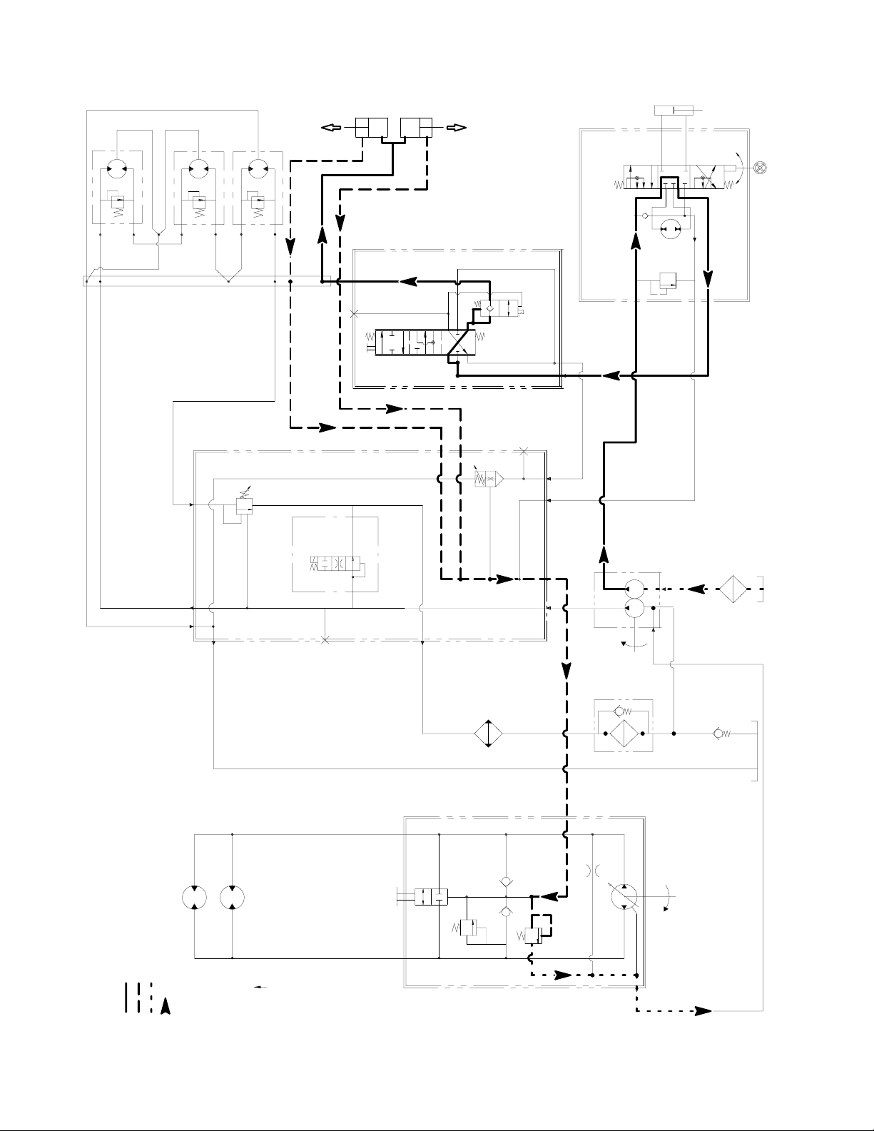
Traction Circuits (Forward)
Groundmaster 3505--D
Working Pressure
Low Pressure (Charge)
Return or Suction
Flow
M5
M4
TRACTION WHEEL
MOTORS
FORWARD
UPPER
DUMP
VALV E
LOWER
PORT
HYDROSTAT
P3
3000 psi
100-- 150 psi
PORT
INTERNAL CASE DRAIN
Groundsmaster 3505--DHydraulic System Page 4 -- 8
Page 39

Traction Circuits
Forward
The traction circuit of the hydraulic system consists of a
hydrostat connected in a closed loop circuit to two orbital
rotor wheel motors.
The engine drives traction pump (P3) indirectly through
pulleys and a V--belt.The traction pump is a variable displacement piston pump. The traction pedal connects
through a cable to the trunnion shaft and swash plate of
the pump. With the engine running and the traction pedal in the neutral position, traction pump (P3) supplies no
flow to the wheel motors. When the traction pedal is
pressed to the forward position, the cable from the pedal
positions the swash plate in the traction pump so oil
flows out of the lower port. Oil flow out of the lower port
goes to the wheel motors and turns them in the forward
direction. Oil flowing out of the wheel motors returns to
the upper port of the hydrostat and is continuously
pumped out of the lower port.
As the load increases, forward traction circuit pressure
can increase to the relief valve setting of 3000 PSI (207
bar). If pressure exceeds the relief setting, oil flows
through the relief valve in the hydrostat to the low pressure side of the closed loop traction circuit.
The traction pump uses a small amount of hydraulic fluid
for internal lubrication. Fluid is designed to leak across
pump parts into the case drain. This leakage results in
the loss of hydraulic fluid from the closed loop traction
circuit that must be replenished.
A two section gear pump is directly coupled to the the hydrostat. Gear pump section (P2) supplies hydraulic flow
for maintaining 100 to 150 PSI (6.9 to 10.3 bar) to the low
pressure side of the traction circuit (charge), raising and
lowering the cutting units and operating the steering
system. The pump replenishes the closed loop traction
circuit with fluid from the hydraulic tank. The charge relief valve in the hydrostat maintains sufficient pressure
so that pump flow is guided to the low pressure side of
the traction circuit through one of two check valves.
Pump flow in excess of replenishment requirements is
relieved through the charge relief valve back to gear
pump (P1) inlet.
Reverse
The traction circuit operates essentially the same in reverse as it does in forward. However, there are a few differences in operation.
When the reverse traction pedal is depressed, the cable
from the pedal positions the swash plate in the traction
pump (P3) so oil flows out of the upper port. Oil flow out
of the upper port goes to the wheel motors and turns
them in the reverse direction. Oil flowing out of the wheel
motors returns to the lower port of the hydrostat and is
continuously pumped out of the upper port.
System
Hydraulic
Groundsmaster 3505--D Hydraulic SystemPage 4 -- 9
Page 40

LEFT
DECK
RIGHT
DECK
REAR
DECK
FRONT
LIFT
CYLINDER
REAR
LIFT
STEERING
CYLINDER
CYLINDER
L
R
POWER
STEERING
VALV E
M1
BULKHEAD
M2
PLATE
M2
M1
D1
M3
FILTER
V1
1000 PSI
OUT (T)
AUX (E)
P2
P1
STRAINER
LIFT VALVE
BA
IN (P)
OUT
IN
OIL
COOLER
G2
LV
ST
CHG
P1
250 psi BACKPRESSURE
GEAR PUMP
OIL
CR
CF
BV
1500 psi
DECK
ON-- OFF
T2
G1
R1
3200 psi
T1
BLOCK
MANIFOLD
LC1
Groundmaster 3505--D
Working Pressure
Low Pressure (Charge)
Cutting Unit Circuit
Return or Suction
Flow
M5
M4
TRACTION WHEEL
MOTORS
FORWARD
BI-- PASS
UPPER
PORT
VALV E
PORT
LOWER
HYDROSTAT
P3
3000 psi
100 to 150 psi
INTERNAL CASE DRAIN
Groundsmaster 3505--DHydraulic System Page 4 -- 10
Page 41

Cutting Unit Circuit
Mow
A two section gear pump is directly coupled to the the hydrostat which is driven by the engine. Gear pump section (P1) supplies oil flow to the cutting unit circuit
through the manifold block and to the cutting unit motors.
Solenoid valve (R1) in the manifold block is de--energized when either the PTO switch is in DISENGAGE or
the transport/mow slide is in TRANSPORT. When de-energized, solenoid valve (R1) by--passes flow from the
cutting unit motors. Flow returns to gear pump (P1) inlet.
Solenoid valve (R1) is energized when the PTO switch
is in ENGAGE and the transport/mow slide is in MOW.
When energized, solenoid valve (R1) allows gear pump
(P1) flow out manifold block port M1 to the cutting unit
motors. When solenoid v alve (R1) is energized, brake
relief cartridge (BV) is shifted (opens) to allow oil return
from the cutting unit motors.
Oil flows through the left, right and then rear cutting unit
motors as it turns the motors. The oil then returns
through manifold block port (M2), the oil cooler, the oil
filter and to gear pump (P1) inlet.
Cutting Unit Blade Braking
When the solenoid valve (R1) is de--energized as the
PTO switch is DISENGAGED, brake relief cartridge
(BV) shifts to its closed position, blocking return flow
from the deck motors and slowing the cutting blades
The inertia of the rotating cutting blades, however,effectively turns the deck motors into pumps causing an increase in pressure as the flow from the motors comes
up against the closed brake relief cartridge (BV). When
this pressure builds to approximately 1500 PSI (103
bar), brake relief c artridge (BV) opens which allows hydraulic flow to return to tank and reduces return pressure. When return pressure drops below 1500 PSI (103
bar), brake relief cartridge (BV) reseats to further slow
the cutting blades. This action repeats several times in
a very short time frame as the blades finally come to a
stop. Once the blades have stopped, brake relief cartridge (BV) remains seated to keep the deck motors
from rotating.
System
Hydraulic
If cutting unit circuit pressure exceeds relief pressure of
3200 PSI (221 bar), solenoid valve (R1) shifts to allow
circuit pressure relief.
Groundsmaster 3505--D Hydraulic SystemPage 4 -- 11
Rev. B
Page 42
LEFT
DECK
DECK
RIGHT
REAR
DECK
FRONT
LIFT
CYLINDER
REAR
LIFT
CYLINDER
CYLINDER
STEERING
L
R
POWER
STEERING
VALV E
M1
BULKHEAD
M2
M1
D1
M2
PLATE
M3
LIFT VALVE
(MOVED TO RAISE)
BA
OUT
IN
OIL
COOLER
G2
LV
ST
CHG
P1
250 psi BACKPRESSURE
GEAR PUMP
OIL
CR
CF
BV
1500 psi
DECK
ON-- OFF
T2
G1
R1
3200 psi
T1
BLOCK
MANIFOLD
LC1
V1
1000 PSI
IN (P)
P2
P1
FILTER
OUT (T)
AUX (E)
STRAINER
Groundmaster 3505--D
Working Pressure
Low Pressure (Charge)
Lift Circuit (Raise)
Return or Suction
Flow
M5
M4
TRACTION WHEEL
MOTORS
FORWARD
BI-- PASS
UPPER
PORT
VALV E
PORT
LOWER
HYDROSTAT
P3
3000 psi
100 to 150 psi
INTERNAL CASE DRAIN
Groundsmaster 3505--DHydraulic System Page 4 -- 12
Page 43

Lift Circuit (Raise)
A two section gear pump is directly coupled to the the hydrostat which is driven by the engine. Gear pump section (P2) supplies hydraulic flow for raising and lowering
the cutting units, operating the steering system and
maintaining 100 to 150 PSI (6.9 to 10.3 bar) to the low
pressure side of the traction circuit (charge). The pump
section (P2) takes its suction from the hydraulic reservoir.
During conditions of not lifting or lowering cutting units,
flow from the gear pump (P2) is by--passed through the
steering control valve, lift control valve and hydraulic
manifold directly to the hydrostat and the charge relief
valve. Flow then returns to the hydraulic tank.
When the cutting units are to be raised, the lift control
valve is positioned by moving the lift control lever to
RAISE. Flow is directed to the cap ends of the lift cylinders. Hydraulic pressure against the cylinder pistons
moves their shafts causing the cutting units to raise. At
the same time, the pistons push the hydraulic fluid out
of the lift cylinders and back through the hydraulic manifold block to the hydrostat (charge).
When the lift control lever is released from RAISE,
spring action returns the valve to its original position and
by--passes flow back to the hydrostat (charge), stopping
lift cylinder movement. The cylinder position is locked in
place by the load holding checks in the lift control valve.
System
Hydraulic
Groundsmaster 3505--D Hydraulic SystemPage 4 -- 13
Page 44

LEFT
DECK
DECK
RIGHT
REAR
DECK
FRONT
LIFT
CYLINDER
REAR
LIFT
CYLINDER
CYLINDER
STEERING
L
POWER
STEERING
VALV E
R
M1
M2
M1
D1
BULKHEAD
M2
PLATE
M3
LIFT VALVE
(MOVED TO LOWER)
BA
IN (P)
IN OUT
CR
CF
BV
1500 psi
DECK
ON-- OFF
T2
G1
R1
3200 psi
T1
LC1
G2
LV
250 psi BACKPRESSURE
ST
CHG
GEAR PUMP
P1
V1
1000 PSI
OUT (T)
AUX (E)
P2
P1
STRAINER
Groundmaster 3505--D
Working Pressure
Low Pressure (Charge)
Lift Circuit (Lower)
Return or Suction
Flow
M5
M4
TRACTION WHEEL
MOTORS
FORWARD
BLOCK
MANIFOLD
OIL
COOLER
UPPER
PORT
VALV E
BI-- PASS
3000 psi
100 to 150 psi
PORT
LOWER
OIL
FILTER
HYDROSTAT
P3
INTERNAL CASE DRAIN
Groundsmaster 3505--DHydraulic System Page 4 -- 14
Page 45

Lift Circuit (Lower)
Circuit operation for lowering the cutting units is similar
to raising them. However, pressure is relieved from the
lift cylinders and this action allows the cutting units to
lower.
During conditions of not lifting or lowering cutting units,
flow from gear pump (P2) is by--passed through the
steering control valve, lift control valve and hydraulic
manifold directly to the hydrostat (charge). Flow then returns to gear pump (P1) inlet.
When the cutting units are to be lowered, the lift control
valve is positioned by moving the lift control lever to
LOWER. Pressure from gear pump (P2) is used to shift
the pilot valve in the control valve.This shifted pilot valve
allows hydraulic pressure to relieve from the c ap end of
the lift cylinders. Flow from the cap end of the lift cylinders causes the cutting units to lower. At the same time,
the fluid relieved from the cap end of the lift cylinders
goes into the rod end of the cylinders and back through
the hydraulic manifold block to the hydrostat (charge).
When the lift control lever is released, spring action returns the valve to its original position and by--passes
flow back to the hydrostat (charge). The pilot valve remains shifted to allow the lift cylinders to float until the
lift control valve is moved to the raise position.
The logic cartridge valve (LC1) in the manifold block
maintains 250 PSI (17.2 bar) back pressure on the lift
cylinders. This counterbalance pressure transfers cutting unit weight to the machine to improve traction.
System
Hydraulic
Groundsmaster 3505--D Hydraulic SystemPage 4 -- 15
Page 46
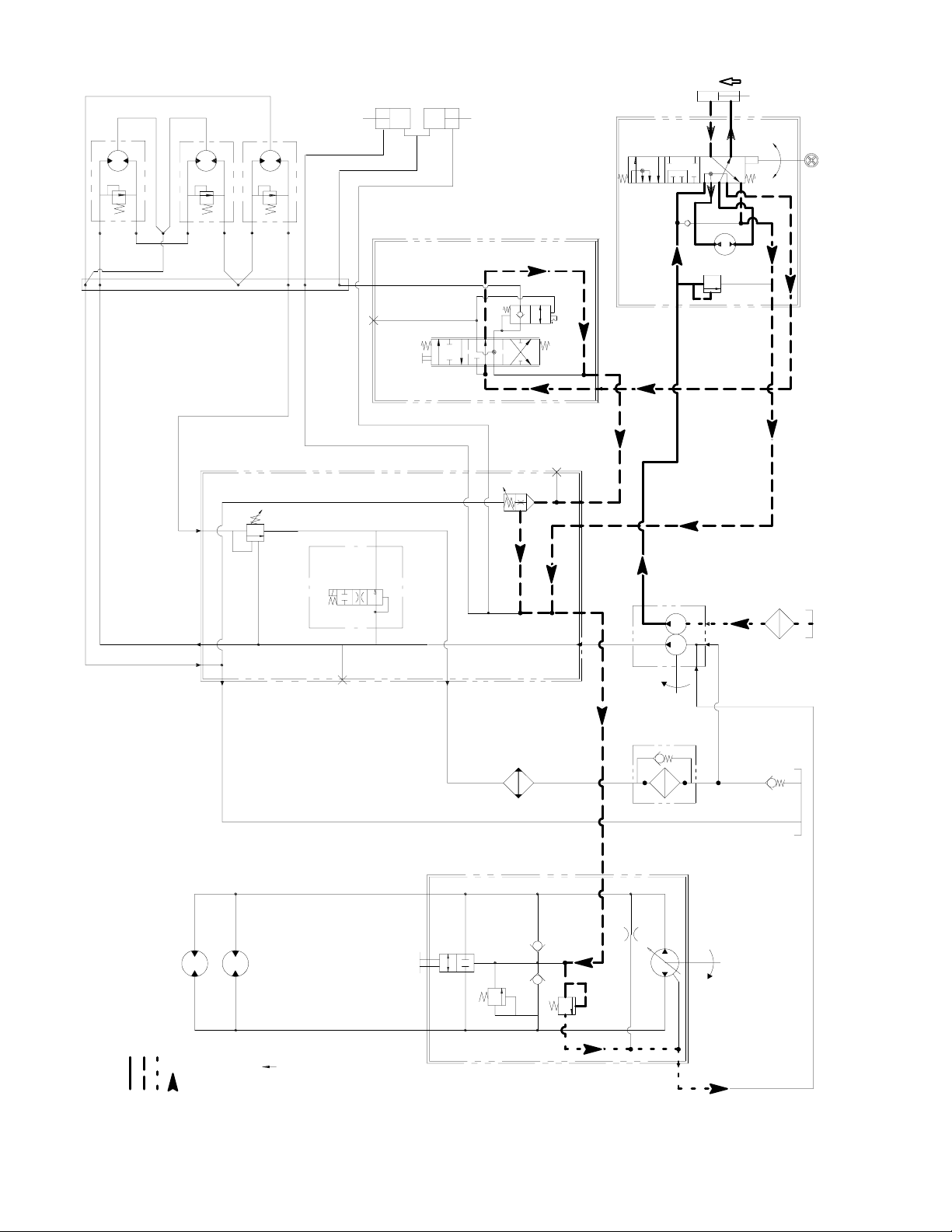
DECK
LEFT
RIGHT
DECK
REAR
DECK
FRONT
LIFT
CYLINDER
REAR
LIFT
CYLINDER
STEERING
CYLINDER
L
R
RETRACTS
FOR RIGHT
TURN
POWER
STEERING
VALV E
M1
M2
M1
D1
BULKHEAD
M2
PLATE
M3
LIFT VALVE
V1
BA
OUT
IN
CR
CF
BV
1500 psi
DECK
ON-- OFF
T2
G1
R1
3200 psi
T1
G2
LV
250 psi BACKPRESSURE
LC1
ST
CHG
GEAR PUMP
P1
1000 PSI
IN (P)
P2
P1
OUT (T)
STRAINER
AUX (E)
Steering Circuit (Right Turn Shown)
Groundmaster 3505--D
Working Pressure
Low Pressure (Charge)
Return or Suction
Flow
M5
M4
TRACTION WHEEL
MOTORS
FORWARD
BLOCK
MANIFOLD
OIL
COOLER
UPPER
PORT
VALV E
BI-- PASS
3000 psi
100 to 150 psi
PORT
LOWER
OIL
FILTER
HYDROSTAT
P3
INTERNAL CASE DRAIN
Groundsmaster 3505--DHydraulic System Page 4 -- 16
Page 47

Steering Circuit
A two section gear pump is directly coupled to the the hydrostat which is driven by the engine. Gear pump section (P2) supplies hydraulic flow for operating the
steering system, raising and lowering the cutting units
and maintaining 100 to 150 PSI (6.9 to 10.3 bar) to the
low pressure side of the traction circuit (charge). The
pump section (P2) takes its suction from the hydraulic
reservoir.
With the engine running and the steering control valve
in the centered position, flow enters the steering control
valve at the IN (P) port and goes through the control
valve, by--passing the rotary meter (V1) and steering
cylinder. Flow leaves the control valve through the AUX
(E) port to be available for the lift circuit and then to the
hydrostat (charge).
Right Turn
When a right turn is made with the engine running, the
turning of the steering wheel positions the control valve
so that flow goes through the bottom of the valve. Flow
entering the steering control v alve at the IN (P) port goes
through the valve and is routed to two places. First, most
of the flow through the valve is by--passed out the AUX
(E) port back through the lift control valve to the hydrostat. Second, the remainder of the flow is drawn through
the rotary meter (V1) and out port (R) to the steering cylinder.Flow to the steering cylinder retracts the piston for
a right turn. The rotary meter (V1) ensures that the oil
flow to the cylinder is proportional to the amount of the
turning on the steering wheel. Fluid leaving the steering
cylinder flows back through the steering control valve
then through the OUT (T) port and to the hydrostat
(charge).
Left Turn
When a left turn is made with the engine running, the
turning of the steering wheel positions the steering control valve so that flow goes through the top of the valve.
Flow entering the steering control valve at the IN (P) port
goes through the spool and is routed to two places. As
in a right turn, most of the flow through the valve is by-passed out the AUX (E) port back through the lift control
and to the hydrostat (charge). Also like a right turn, the
remainder of the flow is drawn through rotary meter ( V1)
but goes out port (L) to the steering cylinder. Flow extends the steering cylinder piston for a left turn. The
rotary meter (V1) ensures that the oil flow to the cylinder
is proportional to the amount of the turning on the steering wheel. Fluid leaving the steering cylinder flows back
through the steering control valve then through the OUT
(T) port and to the hydrostat (charge).
The steering control valve returns to the neutral position
when turning is complete.
System
Hydraulic
The steering control valve returns to the neutral position
when turning is complete.
Groundsmaster 3505--D Hydraulic SystemPage 4 -- 17
Page 48
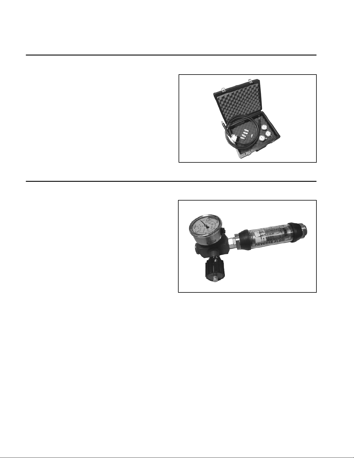
Special Tools
Order these special tools from your Toro Distributor.
Hydraulic Pressure Test Kit
Toro Part Number: TOR47009
Use to take various pressure readings for diagnostic
tests. Quick disconnect fittings provided attach directly
to mating fittings on machine test ports without tools. A
high pressure hose is provided for remote readings.
Contains one each: 1000 PSI (70 Bar), 5000 PSI (350
Bar) and 10000 PSI (700 Bar) gauges. Use gauges as
recommended in Testing section of this chapter.
Hydraulic Tester (Pressure and Flow)
Figure 8
Toro Part Number: TOR214678
This tester requires O--ring Face Seal (ORFS) adapter
fittings for use on this machine (see Hydraulic Test Fitting Kit -- TOR4079 in this section).
1. INLET HOSE: Hose connected from the system circuit to the inlet side of the hydraulic tester.
2. LOAD VALVE: A simulated working load is created
in the circuit by turning the valve to restrict flow.
3. LOW PRESSURE GAUGE: Low range gauge to provide accurate reading at low pressure: 0 to 1000 PSI.
A protector valve cuts out when pressure is about to
exceed the normal range for the gauge. The cutout
pressure is adjustable.
4. HIGH PRESSURE GAUGE: High range gauge
which accommodates pressures beyond the capacity of
the low pressure gauge: 0 to 5,000 PSI.
5. FLOW METER: This meter measures actual oil flow
in the operating circuit with a gauge rated at 15 GPM.
Figure 9
6. OUTLET HOSE: A hose from the outlet side of the
hydraulic tester connects to the hydraulic system circuit.
Rev. B
Groundsmaster 3505--DHydraulic System Page 4 -- 18
Page 49

Hydraulic Test Fitting Kit
Toro Part Number: TOR4079
This kit includes a variety of O--ring Face Seal fittings to
enable the connection of test gauges into the system.
The kit includes: tee’s, unions, reducers, plugs, caps
and male test fittings.
Measuring Container
Toro Part Number: TOR4077
Use this graduated container for doing hydraulic motor
efficiency testing (motors with case drain lines only).
Measure efficiency of a hydrau lic motor by restrictingthe
outlet flow from the motor and measuring leakage from
the case drain line while the motor is pressurized by the
hydraulic system.
Figure 10
System
Hydraulic
The table in Figure 12 provides gallons per minute
(GPM) conversion for measured milliliter or ounce leakage.
Figure 11
Figure 12
Groundsmaster 3505--D Hydraulic SystemPage 4 -- 19
Rev. B
Page 50

O --Ring Kit
Toro Part Number: 16--3799
The kit includes o--rings in a variety of sizes for face seal
and port seal hydraulic connections. It is recommended
that o--rings be replaced whenever a hydraulic connection is loosened.
Wheel Hub Puller
Part Number: TOR4097
The wheel hub puller allows safe removal of the wheel
hub from the shaft of wheel motors.
Figure 13
High Pressure Hydraulic Oil Filter
If a component failure occurs in the closed loop traction
circuit, contamination from the failed part will remain in
the circuit until removed. When connecting hydraulic
test gauges in order to test traction circuit components
or after replacing a failed traction circuit component (e.g.
hydrostat or wheel motor), a high pressure hydraulic filter can be installed in the traction circuit. The filter will
ensure that contaminates are removed from the closed
loop and thus, do not cause additional component damage.
A high pressure hydraulic oil filter can be obtained locally.
Figure 14
Figure 15
Groundsmaster 3505--DHydraulic System Page 4 -- 20
Page 51

This page is intentionally blank.
System
Hydraulic
Groundsmaster 3505--D Hydraulic SystemPage 4 -- 21
Page 52

Troubleshooting
The chart that follows contains information to assist in
troubleshooting. There may possibly be more than one
cause for a machine malfunction.
Problem Possible Cause
Hydraulic oil leaks from system. Fitting(s), hose(s) or tube(s) are loose or damaged.
O--ring(s) or seal(s) are missing or damaged.
Hydraulic fluid foams. Oil level in reservoir is low.
Hydraulic system has wrong type of oil.
One o f the pump suction lines has an air leak.
Incompatible hydraulic oils mixed in system.
Water in hydraulic system.
Hydraulic system operates hot. Transmission pressure is high due to load or brakes applied.
Oil level in reservoir is low or inlet filter is loose or clogged.
Oil is contaminated or oil viscosity is too light.
Oil c ooler is damaged or plugged. By--pass relief is stuck open or
air flow is obstructed.
Refer to the Testing section of this Chapter for precautions and specific hydraulic test procedures.
Hydrostat by--pass valve is open or defective.
Charge pressure is low.
Wheel motor(s) or cutting unit motor(s) are worn or damaged.
Traction pump is worn or damaged.
Neutral is difficult to find or unit operates in one direction only.
Traction response is sluggish. Hydrostat by--pass valve is open or defective.
No traction exists in either direction. Brake is not released.
External control linkage is misadjusted, disconnected, binding or
damaged.
Traction pump is worn or damaged.
Brake is not released.
Charge pressure is low. Hydraulic oil is very cold.
Traction pump or wheel motor(s) are worn or damaged.
Oil level in reservoir is low.
Hydrostat by--pass valve is open.
Traction pump drive belt is loose or broken.
Charge pressure is low.
Traction pump or wheel motor(s) are worn or damaged.
Groundsmaster 3505--DHydraulic System Page 4 -- 22
Page 53

Problem Possible Cause
Wheel motor will not turn. Brakes are binding.
Key on wheel motor shaft is sheared or missing.
Internal parts in wheel motor are damaged.
Wheel motor will not hold load in
Make up fluid from charge pump is not available.
neutral.
Hydrostat ball check valves are damaged.
Cutting unit gear pump (P1) is noisy
Reservoir oil level is low.
(cavitation).
Suction line is restricted.
Suction line has an air leak.
Cutting blades will not turn. Solenoid v alve (R1) is stuck open.
An electrical problem exists (See Chapter 5 -- Electrical System).
Gear pump (P1) is damaged.
Cutting blades(s) turn too slowly. Gear pump (P1) is inefficient (see Testing).
Cutting deck motor has internal leakage or malfunctioning cross-over relief valve (see Testing).
Cutting deck spindle bearing(s) is (are) damaged.
Cutting units will not lift or lift slowly. Engine speed is too low.
Lift cylinder linkage is binding or broken.
Lift arm bushings are binding.
System
Hydraulic
Reservoir oil level is low.
Charge pump (P2) pressure or flow is insufficient.
Charge pump (P2) is damaged.
Implement relief valve (in steering control valve) is stuck open.
Lift cylinders leak internally.
Lift control valve is defective.
Cutting units raise, but will not stay
Lift cylinders leak internally.
up.
Check valve within the lift control valve leaks.
Steering Problems. See Sauer/Danfoss Steering Unit Type OSPM Service Manual at
the end of this chapter.
Turning steering wheel turns ma-
Hoses to the steering cylinder are reversed.
chine in the opposite direction.
Groundsmaster 3505--D Hydraulic SystemPage 4 -- 23
Rev. B
Page 54

This page is intentionally blank.
Groundsmaster 3505--DHydraulic System Page 4 -- 24
Page 55
Testing
The most effective method for isolating problems in the
hydraulic system is by using hydraulic test equipment
such as pressure gauges and flow meters in the circuits
during various operational checks (See the Special
Tools section in this Chapter).
Before Performing Hydraulic Tests
IMPORTANT: All obvious areas such as oil supply,
filter, binding linkages, loose fasteners or improper
adjustments must be checked before assuming that
a hydraulic component is the source of the problem.
Precautions for Hydraulic Testing
CAUTION
Failure to use gauges with expected pressure
(psi) rating as listed in test procedures could result in damage to the gauge and possible personal injury from leaking hot oil.
CAUTION
3. All hydraulic tests should be made with the hydraulic
oil at normal operating temperature.
WARNING
Before disconnecting or performing any work
on the hydraulic system, all pressure in the
system must be relieved. See Relieving Hydraulic System Pressure in the General Information section.
4. Put metal caps or plugs on any hydraulic lines left
open or exposed during testing or component removal.
5. When using hydraulic tester (pressure and flow), the
inlet and the outlet hoses must be properly connected
and not reversed to prevent damage to the hydraulic
tester or components.
6. Install hydraulic fittings finger tight and far enough to
make sure that they are not cross--threaded before tightening them with a wrench.
7. Position tester hoses to prevent rotating machine
parts from contacting and damaging the hoses or tester.
System
Hydraulic
All testing should be performed by two (2)
people. One person should be in the seat to operate the machine and the other should read and
record test results.
WARNING
Keep body and hands away from pin hole leaks
or nozzles that eject hydraulic fluid under high
pressure. Do not use hands to search for
leaks; use paper or cardboard. Hydraulic fluid
escaping under pressure can have sufficient
force to penetrate the skin and cause serious
injury. If fluid is injected into the skin, it must
be surgically removed within a few hours by a
doctor familiar with this type of injury. Gangrene may result from such an injury.
1. Clean machine thoroughly before disconnecting or
disassembling any hydraulic components. Always keep
in mind the need for cleanliness when working on hydraulic equipment. Contamination can cause excessive
wear or binding of hydraulic components.
2. Before testing, check control linkages for improper
adjustment, binding or broken parts.
8. After connecting test equipment, check oil level in
the hydraulic tank to make sure that oil level is correct.
9. When using hydraulic tester (pressure and flow),
open tester load valve completely before starting engine
to minimize the possibility of damaging components.
10.The engine must be in good operating condition. Use
a phototac when performing a hydraulic test. Engine
speed can affect the accuracy of the tester readings.
Check actual speed of the pump when performing hydraulic flow tests.
11. If a traction circuit problem exists, consider performing one or more of the following tests: Traction Circuit
Working Pressure, Charge Relief Valve Pressure, Piston Pump (P3) Flow & Traction Relief Pressure and/or
Wheel Motor Efficiency Tests.
12.If a cutting circuit problem exists, consider performing one or more of the following tests: Cutting Deck Circuit Pressure, Manifold Relief Valve (R1) Pressure,
Logic (Counterbalance) Valve (LC1) Pressure, Gear
Pump (P1) Flow and/or Deck Motor Efficiency Tests.
13.If a steering or lift circuit problem exists, consider performing one or more of the following tests: Steering and
Lift Relief Pressure, Gear Pump (P2) Flow and/or Steering Control Valve Tests.
Groundsmaster 3505--D Hydraulic SystemPage 4 -- 25
Page 56

Traction Circuit Working Pressure Test (Using Pressure Gauge)
M5
TRACTION WHEEL MOTORS
M4
PRESSURE
GAUGE
FORWARD
LOWER
PORT
BI--PASS
VALVE
3000 psi
TRACTION
RELIEF
100 to 150 psi
CHARGE
RELIEF
UPPER
PORT
FROM HYDRAULIC
MANIFOLD (CHARGE) PORT
TO GEAR PUMP SUCTION
THROUGH CASE DRAIN
P3
PISTON PUMP
(HYDROSTAT)
Working Pressure
Low Pressure (Charge)
Return or Suction
Flow
Groundsmaster 3505--DHydraulic System Page 4 -- 26
Page 57

Procedure for Traction Circuit Working Pressure
Test:
1. Make sure hydraulic oil is at normal operating temperature. Park machine on a level surface with the cutting units lowered and off. Make sure engine is off.
2. Read Precautions for Hydraulic Testing.
3. Make sure that traction pedal is adjusted to the neutral position (see Traction Unit Operator’s Manual).
2
1
WARNING
Before disconnecting or performing any work
on the hydraulic system, all pressure in the
system must be relieved. See Relieving Hydraulic System Pressure in the General Information section.
4. Remove plug from hydraulic tube connected to front
wheel motors (Fig. 16). Connect test gauge with an attached hydraulic hose to the hydraulic tube opening.
Make sure hose is long enough so the operator can read
gauge while driving the machine.
5. Start engine and move throttle to full speed (3050 +
50 RPM).
6. Drive machine in the forward direction. Observe test
gauge:
A. Pressure while transporting the machine over a
flat, level surface should be about 500 PSI.
B. Pressure driving the machine up a hill should be
about 2500 PSI but can reach relief settings (3000
PSI).
Figure 16
1. Hydraulic tube with plug 2. Floor plate
System
Hydraulic
C. Pressure while mowing should range between
1000 to 2000 PSI and will vary with terrain conditions.
7. Release traction pedal and turn off machine. Record
test results.
8. If specification is not met, the hydrostat needs to be
repaired or replaced as necessary.
9. Relieve hydraulic system pressure (See Relieving
Hydraulic System Pressure in the General Information
section). Disconnect test gauge and hose from the hydraulic tube. Install plug into tube opening.
Groundsmaster 3505--D Hydraulic SystemPage 4 -- 27
Page 58

Charge Relief Valve Pressure Test (Using Pressure Gauge)
M5
TRACTION WHEEL MOTORS
M4
FORWARD
LOWER
PORT
BI-- PASS
VALV E
3000 psi
TRACTION
RELIEF
100 to 150 psi
CHARGE
RELIEF
UPPER
PORT
TO HYDRAULIC
MANIFOLD (P1) PORT
PRESSURE
GAUGE
FROM HYDRAULIC MANIFOLD
(CHG) PORT
TO STEERING CONTROL
VALVE (IN) PORT
P3
ENGINE
RPM
P1 P2
INTERNAL CASE DRAIN
HYDROSTAT
FROM OIL
FILTER
GEAR PUMP
STRAINER
Working Pressure
Low Pressure (Charge)
Return or Suction
Flow
Groundsmaster 3505--DHydraulic System Page 4 -- 28
Page 59

Procedure for Charge Relief Valve Pressure
1. Make sure hydraulic oil is at normal operating temperature.
2. Park machine on a level surface with the cutting units
lowered and off. Make sure engine is off and the parking
brake is engaged.
Test:
NOTE: If charge pressure is good under no load, but
drops below specification when under traction load, the
piston pump and/or wheel motor(s) should be suspected of wear. When a pump and/or motor is worn or
damaged, the charge pump is not able to keep up with
internal leakage in the traction circuit.
10.Stop machine and shut off engine.
3. Read Precautions for Hydraulic Testing.
WARNING
Before disconnecting or performing any work
on the hydraulic system, all pressure in the
system must be relieved. See Relieving Hydraulic System Pressure in the General Information section.
4. Disconnect hose to the rear 90ohydraulic fitting on
the piston pump coming from the hydraulic manifold port
(CHG). Connect T--connector and hydraulic pressure
gauge to the fitting and hose connection.
5. Make sure that traction pedal is in neutral and the
parking brake is engaged.
6. Start engine and operate engine at full speed (3050
+
50 RPM).
7. Pressure gauge should read from 100 to 150 PSI.
Record test result.
11. Relieve hydraulic system pressure (See Relieving
Hydraulic System Pressure in the General Information
section). Disconnect gauge and T--connection from the
o
90
hydraulic fitting and hose connection. Reconnect
hose to the hydrostat.
2
1
Figure 17
1. 90ohydraulic fitting 2. Piston pump
System
Hydraulic
8. If charge relief pressure specification is not met, consider the following:
A. The piston pump charge relief valve is faulty. Repair or replace the piston pump charge relief valve
(see Piston Pump Service in the Service and Repairs
section).
B. Gear pump (P2) is faulty (steering and lift circuits
are also affected).
9. A dynamic charge pressure test can be performed as
follows:
A. With T--connector and hydraulic pressure gauge
still connected, sit in the operator seat and press the
traction pedal to forward.
B. While machine is moving, monitor the charge
pressure reading on the pressure guage.
C. The charge pressure should drop no more than
15% from initial test reading (Step 7 above) as the
machine is moving. A pressure drop of more than
15% indicates a traction circuit leak (e.g. a worn or
damaged piston pump and/or wheel motor).
Groundsmaster 3505--D Hydraulic SystemPage 4 -- 29
Page 60

Piston Pump (P3) Flow and Traction Relief Pressure Test (Using Tester with Pressure
Gauges and Flow Meter)
M5
TRACTION WHEEL MOTORS
M4
FORWARD
HYDRAULIC
TESTER
LOWER
PORT
BI--PASS
VALVE
3000 psi
TRACTION
RELIEF
100 to 150 psi
CHARGE
RELIEF
UPPER
PORT
FROM HYDRAULIC
MANIFOLD (CHARGE) PORT
TO GEAR PUMP SUCTION
THROUGH CASE DRAIN
P3
PISTON PUMP
(HYDROSTAT)
Working Pressure
Low Pressure
Return or Suction
Flow
Groundsmaster 3505--DHydraulic System Page 4 -- 30
Page 61
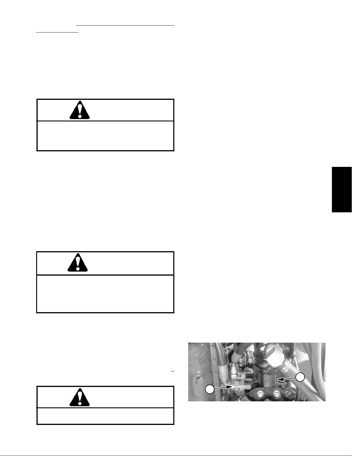
Procedure for Piston Pump (P3) Flow and T
Relief Pressure
1. Make sure hydraulic oil is at normal operating temperature. Park machine on a level surface with the cutting units lowered and off. Make sure engine is off.
Test:
raction
11. Slowly push traction pedal fully to forward position.
12.Verify traction relief valve setting by slowly closing
flow control valve on tester. System pressure should be
3000 PSI as the relief v alve lifts. Release traction pedal
and open tester flow control valve fully.
2. Read Precautions for Hydraulic Testing.
3. Make sure that traction pedal is adjusted to the neutral position (see Traction Unit Operator’s Manual).
CAUTION
One front wheel will be off the ground during
testing. Make sure machine is supported so it will
not move and accidentally fall to prevent injuring
anyone under machine.
4. Block up one front traction wheel off the ground to allow flow through the traction circuit; disconnect brake
linkage to the raised front wheel (see Adjust Brakes in
the Adjustments section of Chapter 7 -- Chassis).
5. Chock remaining front wheel to prevent movement
of the machine.
6. Attach a heavy chain to the rear of the machine frame
and something immovable in the shop.
7. Make sure parking brake is on to keep the wheel on
the ground from rotating.
WARNING
Before disconnecting or performing any work
on the hydraulic system, all pressure in the
system must be relieved. See Relieving Hydraulic System Pressure in the General Information section.
13.If relief pressure specification is not met, consider
the following:
A. The traction belt may be worn or slipping.
B. The traction relief valve leaks or is faulty.
C. The hydrostat needs to be repaired or replaced.
14.If the traction relief valve tests properly, verify piston
pump (P3) flow as follows:
A. Slowly push traction pedal in forward direction
until pressure gauge reads 1000 PSI. Verify with a
phototac that the pump speed is 2350 RPM (engine
speed approximately 2450 RPM).
B. Observe flow gauge. TESTER READING should
be approximately 12.5 GPM.
15.Release traction pedal and turn off machine. Record
test results.
NOTE: If charge pressure is good under no load, but
drops below specification when under traction load, the
piston pump and/or wheel motor(s) should be suspected of wear. When a pump and/or motor is worn or
damaged, the charge pump is not able to keep up with
internal leakage in the traction circuit (See Charge Relief Valve Pressure Test in this section).
16.If specifications are not met, the hydrostat needs to
be repaired or replaced as necessary.
17.Relieve hydraulic system pressure (See Relieving
Hydraulic System Pressure in the General Information
section). Disconnect tester from hydraulic fitting and
hose. Reconnect hose to pump connection.
System
Hydraulic
8. Disconnect hose from the lower hydraulic fitting on
the engine side of the hydrostat (Fig. 18).
9. Install hydraulic tester (pressure and flow) in series
with the pump and the disconnected hose. Make sure
the tester flow control valve is fully open.
10.Start engine and move throttle to full speed (3050 +
50 RPM).
18.Connect brake linkage to wheel (see Adjust Brakes
in the Adjustments section of Chapter 7 -- Chassis).
CAUTION
During testing, the front wheel on the ground will
be trying to move the machine forward.
Groundsmaster 3505--D Hydraulic SystemPage 4 -- 31
1. Lower hydraulic fitting 2. Piston pump
2
1
Figure 18
Page 62
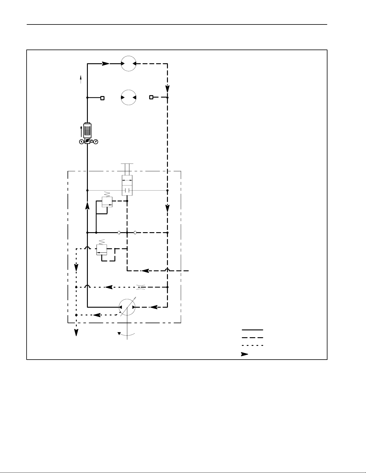
Wheel Motor Efficiency Test (Using Tester with Pressure Gauges and Flow Meter)
M5
TRACTION WHEEL
MOTORS
M4
FORWARD
HYDRAULIC
TESTER
LOWER
PORT
DUMP
VALVE
3000 psi
TRACTION
RELIEF
100 to 150 psi
CHARGE
RELIEF
TO GEAR PUMP SUCTION
THROUGH CASE DRAIN
P3
UPPER
PORT
PISTON PUMP
(HYDROSTAT)
FROM HYDRAULIC
MANIFOLD (CHG) PORT
High Pressure
Low Pressure
Return or Suction
Flow
NOTE: Over a period of time, a wheel motor can wear
internally. A worn motor may by--pass oil to its case drain
causing the motor to be less efficient. Eventually,
enough oil loss will cause the wheel motor to stall under
heavy load conditions. Continued operation with a worn,
inefficient motor can generate excessive heat, cause
damage to seals and other components in the hydraulic
system and affect overall machine performance.
Groundsmaster 3505--DHydraulic System Page 4 -- 32
Page 63
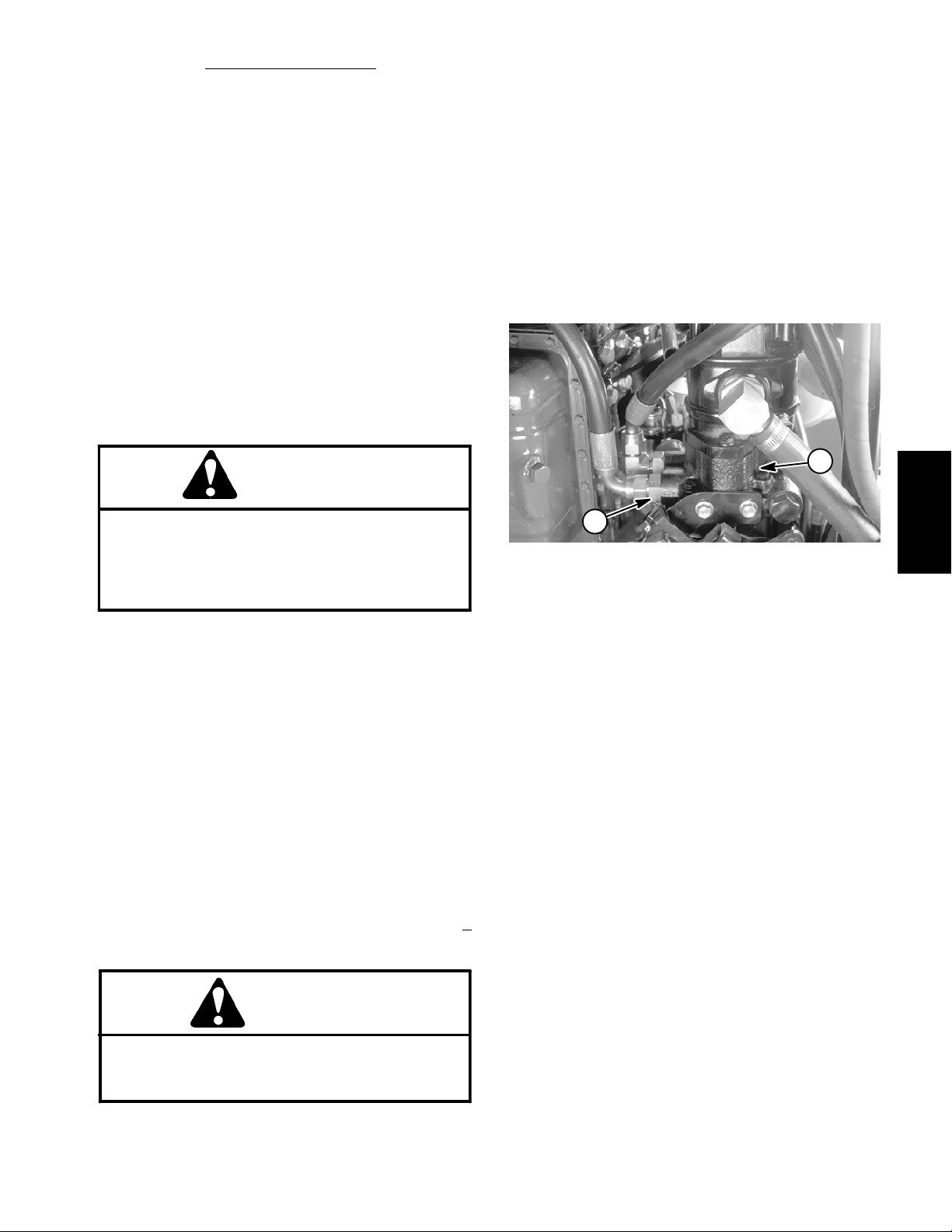
Procedure for Wheel Motor Efficiency
1. Make sure hydraulic oil is at normal operating temperature. Make sure the hydraulic tank is full.
2. Park machine on a level surface with the cutting units
lowered and off. Make sure engine is off and the parking
brake is engaged.
3. Read Precautions for Hydraulic Testing.
4. Make sure that traction pedal is adjusted to the neutral position (see Adjust Traction Drive for Neutral in the
Adjustments Section).
5. Attach a heavy chain to the rear of the machine frame
and an immovable object to prevent the machine from
moving during testing.
6. Chock front wheel being tested to prevent rotation of
the w heel. Make sure parking brake is on.
Test:
WARNING
12.Motor internal leakage will be shown on flow meter
in GPM. Flow should be less than 1.5 GPM for the
tested wheel motor.
13.If specifications are not met, the tested wheel motor
needs to be repaired or replaced as necessary.
14.If remaining front wheel motor requires testing, complete steps 5 to 14 for the remaining motor.
15.Relieve hydraulic system pressure (See Relieving
Hydraulic System Pressure in the General Information
section). Disconnect tester from hydraulic fitting and
hose. Reconnect hose to pump connection.
2
Before disconnecting or performing any work
on the hydraulic system, all pressure in the
system must be relieved. See Relieving Hydraulic System Pressure in the General Information section.
7. Disconnect hydraulic lines from front wheel motor
that is not being tested. Cap disconnected hydraulic
lines and plug ports in wheel motor to prevent contamination.
8. Disconnect hose from the lower hydraulic fitting on
the bottom of the hydrostat (Fig. 19).
NOTE: An alternate testing location would be at the hydraulic hose connection to the hydraulic tube under the
left floor plate.
9. Install hydraulic tester (pressure and flow) in series
with the pump and the disconnected hose. Make sure
the tester flow control valve is fully open.
10.Start engine and move throttle to full speed (3050 +
50 RPM).
1
Figure 19
1. Lower hydraulic fitting 2. Piston pump
System
Hydraulic
CAUTION
Use extreme caution when performing test. The
front tire on the ground will be trying to move the
machine forward.
11. Slowly push traction pedal in forward direction until
1000 PSI is displayed on the tester pressure gauge.
Groundsmaster 3505--D Hydraulic SystemPage 4 -- 33
Page 64

Cutting Deck Circuit Pressure Test (Using Pressure Gauge)
FROM DECK MOTOR
CASE DRAINS
TO LEFT FRONT
DECK MOTOR
TO HYDRAULIC
TANK
T2
D1
M1
1500 psi
M2
BV
FROM REAR
DECK MOTOR
PRESSURE
GAUGE
TO OIL
COOLER
G1
T1
DECK
ON--OFF
R1
3200 psi
(ENERGIZED)
LC1
HYDRAULIC
MANIFOLD
BLOCK
CF
CR
FROM FRONT LIFT
CYLINDER
FROM REAR LIFT
CYLINDER
TO HYDROSTAT
CHARGE CIRCUIT
ENGINE
RPM
FROM HYDROSTAT
INTERNAL CASE DRAIN
FROM OIL FILTER
P1
P1 P2
CHG
STRAINER
ST
GEAR PUMP
G2
LV
FROM LIFT VALVE
(OUT) PORT
TO STEERING CONTROL
VALVE ( IN) PO RT
FROM STEERING CONTROL
VALVE ( OUT) PORT
Working Pressure
Low Pressure
Return or Suction
Flow
Groundsmaster 3505--DHydraulic System Page 4 -- 34
Page 65

Procedure for Cutting Deck Circuit Pressure
Test:
1. Make sure hydraulic oil is at normal operating temperature.
2. Park machine on a level surface with the cutting units
lowered and off. Make sure engine is off and the parking
brake is engaged.
3. Read Precautions for Hydraulic Testing.
WARNING
Before disconnecting or performing any work
on the hydraulic system, all pressure in the
system must be relieved. See Relieving Hydraulic System Pressure in the General Information section.
4. Remove plug from hydraulic manifold port (G1).
5. Install hydraulic pressure gauge with hydraulic hose
attached to the manifold port (G1).
CAUTION
1
2
Figure 20
1. Hydraulic manifold 2. Manifold port (G1)
2
1
System
Hydraulic
Keep away from decks during test to prevent personal injury from the cutting blades.
6. Start engine and move throttle to full speed (3050 +
50 RPM). Engage the cutting units.
7. Watch pressure gauge carefully while mowing with
the machine.
8. Cutting circuit pressure should be from 1000 to 1500
PSI and will vary depending on mowing conditions.
9. Disengage cutting units. Shut off engine. Record test
results.
10.Relieve hydraulic system pressure (See Relieving
Hydraulic System Pressure in the General Information
section). Disconnect pressure gauge with hose from
manifold block. Reconnect plug to the hydraulic manifold port (G1).
Figure 21
1. Hydraulic manifold 2. Manifold port (G1)
Groundsmaster 3505--D Hydraulic SystemPage 4 -- 35
Page 66

Manifold Relief Valve (R1) Pressure Test (Using Pressure Gauge and Tester with Pressure Gauges and Flow Meter)
FROM DECK MOTOR
CASE DRAINS
TO LEFT FRONT
DECK MOTOR
1500 psi
M2
FROM REAR
DECK MOTOR
BV
TO HYDRAULIC
TANK
T2
D1
M1
HYDRAULIC
TESTER
PRESSURE
GAUGE
TO OIL
COOLER
TO HYDROSTAT
CHARGE CIRCUIT
G1
T1
P1
DECK
ON--OFF
CHG
R1
3200 psi
(ENERGIZED)
ST
LC1
LV
HYDRAULIC
MANIFOLD
BLOCK
CF
CR
FROM FRONT LIFT
CYLINDER
FROM REAR LIFT
CYLINDER
G2
FROM LIFT VALVE
(OUT) PORT
ENGINE
RPM
FROM HYDROSTAT
INTERNAL CASE DRAIN
FROM OIL FILTER
P1 P2
GEAR PUMP
STRAINER
TO STEERING CONTROL
VALVE ( IN) PO RT
FROM STEERING CONTROL
VALVE ( OUT) PORT
Working Pressure
Low Pressure
Return or Suction
Flow
Groundsmaster 3505--DHydraulic System Page 4 -- 36
Page 67

Procedure for Manifold Relief Valve (R1) Pressure
Test:
1. Make sure hydraulic oil is at normal operating temperature.
2. Park machine on a level surface with the cutting units
lowered and off. Make sure engine is off and the parking
brake is engaged.
3. Read Precautions for Hydraulic Testing.
10.Relieve hydraulic system pressure (See Relieving
Hydraulic System Pressure in the General Information
section). Disconnect tester from manifold and hose. Reconnect hydraulic hose that was disconnected for test
procedure.
1
WARNING
Before disconnecting or performing any work
on the hydraulic system, all pressure in the
system must be relieved. See Relieving Hydraulic System Pressure in the General Information section.
4. Disconnect hose connection from hydraulic fitting on
manifold port (M1) (Figure 22).
NOTE: An alternative to using manifold port (M1) would
be to disconnect the inlet hydraulic hose to the front, left
deck motor. The motor inlet is opposite from the relief
valve on the motor (Figure 24).
5. Install hydraulic tester (pressure and flow) in series
with the hose and hydraulic fitting. Make sure the flow
control v alve on tester is fully open.
CAUTION
Keep away from decks during test to prevent personal injury from the cutting blades.
6. Start engine and move throttle to full speed (3050 +
50 RPM). Engage the cutting units.
2
Figure 22
1. Hydraulic manifold 2. Manifold port (M1)
2
Figure 23
1. Hydraulic manifold 2. Manifold port (M1)
System
Hydraulic
1
7. Watch pressure gauge carefully while slowly closing
the flow control valve to fully closed.
8. System pressure should be from 3350 to 3600 PSI
as the relief valve lifts.
A. If specification is not met, shut off engine and
clean or replace solenoid cartridge valve (R1) valve
(see Hydraulic Manifold Service in the Service and
Repairs section). Return to step 5.
B. If this specification is met, proceed to step 9.
9. Disengage cutting units. Shut off engine. Record test
results.
Groundsmaster 3505--D Hydraulic SystemPage 4 -- 37
1. Hydraulic deck motor
2. Inlet hose
3
2
1
Figure 24
3. Relief valve
Page 68

Logic (Counterbalance) Valve (LC1) Pressure Test (Using Pressure Gauge)
FROM DECK MOTOR
CASE DRAINS
TO LEFT FRONT
DECK MOTOR
FROM REAR
DECK MOTOR
TO HYDRAULIC
TANK
T2
D1
M1
M2
BV
1500 psi
TO OIL
COOLER
G1
T1
DECK
ON--OFF
(NOT ENERGIZED)
R1
3200 psi
LC1
HYDRAULIC
MANIFOLD
BLOCK
CF
CR
FROM FRONT LIFT
CYLINDER
FROM REAR LIFT
CYLINDER
TO HYDROSTAT
CHARGE CIRCUIT
ENGINE
RPM
FROM HYDROSTAT
INTERNAL CASE DRAIN
FROM OIL FILTER
P1
P1 P2
CHG
STRAINER
ST
GEAR PUMP
PRESSURE
G2
GAUGE
LV
FROM LIFT VALVE
(OUT) PORT
TO STEERING CONTROL
VALVE ( IN) PO RT
FROM STEERING CONTROL
VALVE ( OUT) PORT
Groundsmaster 3505--DHydraulic System Page 4 -- 38
High Pressure
Low Pressure
Return or Suction
Flow
Page 69

Procedure for Logic (Counterbalance) Valve
Pressure
NOTE: If the counterbalance system is functioning, the
machine should normally settle slightly when the engine
is started.
1. Make sure hydraulic oil is at normal operating temperature.
Test:
(LC1)
C. To increase pressure setting, turn the adjustment shaft on the valve in a clockwise direction. A 1/8
turn on the shaft will make a measurable change in
counterbalance pressure.
D. To decrease pressure setting, turn the adjustment shaft on the valve in a counterclockwise direction. A 1/8 turn on the shaft will make a measurable
change in counterbalance pressure.
2. Park machine on a level surface with the cutting units
lowered and off. Make sure engine is off and the parking
brake is engaged.
3. Read Precautions for Hydraulic Testing.
WARNING
Before disconnecting or performing any work
on the hydraulic system, all pressure in the
system must be relieved. See Relieving Hydraulic System Pressure in the General Information section.
4. Remove plug from hydraulic manifold port (G2) (Fig.
25).
5. Install hydraulic pressure gauge with hydraulic hose
attached to port (G2).
CAUTION
Keep away from decks during test to prevent personal injury from the cutting blades.
E. Tightenlock nut. Check counterbalance pressure
(steps 6 and 7) and readjust as needed.
F. Replace hex cap to Logic valve (LC1).
9. Shut off engine.
10.Relieve hydraulic system pressure (See Relieving
Hydraulic System Pressure in the General Information
section). Disconnect test gauge with hose from manifold
block. Install plug into hydraulic manifold port (G2) and
torque plug 120 in--lb (13.6 N--m).
1
2
Figure 25
1. Hydraulic manifold 2. Manifold port (G2)
System
Hydraulic
6. Start engine and move throttle to full speed (3050 +
50 RPM). Do not engage or raise the cutting units.
7. The standard counterbalance pressure should be
250 PSI with a range of 180 to 300 psi.
8. If necessary,adjustment of the Logic valve (LC1) can
be performed as follows:
NOTE: Do not remove the Logic valve from the hydraulic manifold for adjustment.
A. Remove hex cap from logic valve (Fig. 26).
B. Loosen lock nut.
Groundsmaster 3505--D Hydraulic SystemPage 4 -- 39
1. Manifold assembly
2. Logic valve (LC1)
3
4
2
1
Figure 26
3. Hex cap
4. Lock nut
Page 70

Gear Pump (P1) Flow Test (Using Tester with Pressure Gauges and Flow Meter)
TO HYDRAULIC MANIFOLD
(P1) PORT
HYDRAULIC
TESTER
TO STEERING CONTROL
VALVE ( IN) PO RT
TO TOTO
ENGINE
RPM
FROM HYDROSTAT
CASE DRAIN
FROM OIL FILTER
P1 P2
GEAR PUMP
STRAINER
Working Pressure
Low Pressure
Return or Suction
Flow
Groundsmaster 3505--DHydraulic System Page 4 -- 40
Page 71

Procedure for Gear Pump (P1) Flow
NOTE: Over a period of time, the gears and wear plates
in the pump can wear. A worn pump will by pass oil and
make the pump less efficient. Eventually,enough oil loss
will occur to cause the cutting unit motors to stall under
heavy cutting conditions. Continued operation with a
worn, inefficient pump can generate excessive heat and
cause damage to the seals and other components in the
hydraulic system.
Test:
11. If flow was less than 11.8 GPM or a pressure of 2000
PSI cannot be obtained, check for restriction in the pump
intake line. If line is not restricted, remove gear pump
(P1) and repair or replace as necessary.
12.Relieve hydraulic system pressure (See Relieving
Hydraulic System Pressure in the General Information
section). Disconnect tester from gear pump fitting and
hose. Reconnect hose to the pump.
1. Make sure hydraulic oil is at normal operating temperature.
2. Park machine on a level surface with the cutting units
lowered and off. Make sure engine is off and the parking
brake is engaged.
3. Read Precautions for Hydraulic Testing.
WARNING
Before disconnecting or performing any work
on the hydraulic system, all pressure in the
system must be relieved. See Relieving Hydraulic System Pressure in the General Information section.
4. Disconnect hose connection on the gear pump (P1)
leading to port (P1) on the hydraulic manifold (Fig. 27).
5. Install hydraulic tester (pressure and flow) in series
with the gear pump and the disconnected hose leading
to port (P1) on the hydraulic manifold.
2
RIGHT
1
FRONT
Figure 27
1. Gear pump (P1) 2. To hydraulic manifold
System
Hydraulic
6. Make sure the flow control valve on the tester is fully
open.
7. Start engine and move throttle to full speed (3050 +
50 RPM). Do not engage the cutting units.
IMPORTANT: In this test, the hydraulic tester is
positioned before the manifold relief valve. Pump
damage can occur if the oil flow is fully restricted by
fully closing the tester flow control valve. Do not
close tester valve fully when performing test.
8. Watch tester pressure gauge carefully while slowly
closing the flow control v alve until 2000 PSI is obtained.
Do not close tester load valve fully.Verifywith a phototac
that the pump speed is 3100 RPM while maintaining
2000 PSI.
9. Flow indication should be 11.8 GPM minimum.
10.Shut off engine. Record test results.
Groundsmaster 3505--D Hydraulic SystemPage 4 -- 41
Page 72

Deck Motor Efficiency -- Case Drain Test (Using Tester with Pressure Gauges and Flow
Meter)
TO HYDRAULIC
MANIFOLD PORT (D1)
FROM HYDRAULIC
MANIFOLD PORT (M1)
TO HYDRAULIC
MANIFOLD PORT (M2)
LEFT
DECK MOTOR
RIGHT
DECK MOTOR
REAR
DECK MOTOR
HYDRAULIC
TESTER
MEASURING
CONTAINER
Working Pressure
Low Pressure
Return or Suction
Flow
# TOR4077
NOTE: Over a period of time, a deck motor can wear in-
ternally. A worn motor may by--pass oil to its case drain
causing the motor to be less efficient. Eventually,
enough oil loss will cause the deck motor to stall under
heavy cutting conditions. Continued operation with a
worn, inefficient motor can generate excessive heat,
cause damage to seals and other components in the hydraulic system and affect quality of cut.
NOTE: One method to identify a possibly bad deck motor is to have another person observe the machine while
mowing in dense turf. A bad motor will run slower, produce fewer clippings and could cause a different appearance in the turf.
Groundsmaster 3505--DHydraulic System Page 4 -- 42
Page 73

Procedure for Deck Motor Efficiency -- Case Drain
Test:
1. Make sure hydraulic oil is at normal operating temperature.
10.After achieving 1200 PSI, place disconnected motor
case drain hose into a container graduated in ounces or
milliliters (e.g. Toro #TOR4077) and collect hydraulic
fluid for 15 seconds. After 15 seconds, remove hose end
from container.
2. Remove blades from all cutting decks (see Cutting
Unit Operator’s Manual).
3. Park machine on a level surface with the cutting units
lowered and off. Make sure engine is off and the parking
brake is engaged.
4. Read Precautions for Hydraulic Testing.
WARNING
Before disconnecting or performing any work
on the hydraulic system, all pressure in the
system must be relieved. See Relieving Hydraulic System Pressure in the General Information section.
NOTE: The deck motors are connected in series. To
isolate a faulty motor, all three motors in the cutting circuit may have to be tested by starting with the upstream
motor first.
5. For the suspected bad deck motor, disconnect return
hose from the motor. Note: the return hose is on the motor side that includes the relief valve (Fig. 28).
11. Stop cutting units by positioning the PTO switch to
the DISENGAGE position. Stop engine.
12.Identify amount of oil collected in the container. Record test results.
13.If flow was greater than 22.4 ounces (662 millili-
ters), r epair or replace the tested deck motor.
14.Relieve hydraulic system pressure (See Relieving
Hydraulic System Pressure in the General Information
section). Disconnect tester from motor and hose. Reconnect hydraulic hoses.
15.Repeat test with other deck motors as needed.
16.Install cutting blades after testing is completed (see
Cutting Unit Operator’s Manual).
4
3
System
Hydraulic
6. Install hydraulic tester (pressure and flow) in series
with the motor and the disconnected return hose. Make
sure the tester flow control valve is fully open.
7. Disconnect hose from deck motor case drain at the
bulkhead T--fitting (Fig. 29). Plug the T--fitting. Place
open end of disconnected case drain hose into a drain
pan.
8. One person should sit on the seat and operate the
machine while another person reads the tester and
measures deck motor case drain leakage. Make sure
traction pedal is in NEUTRAL. Start engine and move
the throttle to full speed (3050 +
50 RPM).
CAUTION
Keep away from decks during test to prevent personal injury from rotating parts.
9. Engage decks by positioning the PTO switch to the
ENGAGE position. While watching hydraulic tester
pressure gauge, slowly close flow control valve until a
pressure of 1200 PSI is obtained.
2
1. Deck motor
2. Return line
6
5
RIGHT
FRONT
4
1. Deck motor
2. Rear case drain hose
3. Rear T--fitting
1
Figure 28
3. Relief valve
4. Case drain hose
3
2
1
1
Figure 29
4. Front LH case drain
5. Front RH case drain
6. Front T--fitting
Groundsmaster 3505--D Hydraulic SystemPage 4 -- 43
Page 74

Steering and Lift Relief Pressure Test (Using Pressure Gauge)
TO HYDRAULIC
MANIFOLD
(ST) PORT
TO LIFT VAL VE
(IN) PORT
IN (P)
L
TO HYDRAULIC
MANIFOLD
(P1) PORT
ENGINE
RPM
P1 P2
OUT (T)
AUX (E)
PRESSURE
GAUGE
GEAR PUMP
STRAINER
1000 psi
V1
R
POWER
STEERING
VALVE
STEERING
FROM
OIL FILTER
FROM HYDROSTAT
INTERNAL CASE DRAIN
Working Pressure
Low Pressure
Return or Suction
Flow
Groundsmaster 3505--DHydraulic System Page 4 -- 44
Page 75

Procedure for Steering and Lift Relief Pressure
Test:
1. Make sure hydraulic oil is at normal operating temperature.
2. Park machine on a level surface with the cutting units
lowered and off. Make sure engine is off and the parking
brake is engaged.
12.Relieve hydraulic system pressure (See Relieving
Hydraulic System Pressure in the General Information
section). Disconnect T--connector with test gauge from
pump connection and hose. Reconnect hydraulic hose
to gear pump (P2).
2
3. Read Precautions for Hydraulic Testing.
WARNING
Before disconnecting or performing any work
on the hydraulic system, all pressure in the
system must be relieved. See Relieving Hydraulic System Pressure in the General Information section.
4. Disconnect hose connection on gear pump (P2)
leading to the steering control valve (Fig. 30).
5. Install T--connector with hydraulic pressure gauge in
series with the discharge of the gear pump and the disconnected hose leading to the steering control valve.
6. Make sure steering wheel is positioned so the rear
wheel points directly ahead.
7. Start engine and move throttle to full speed (3050 +
50 RPM).
RIGHT
FRONT
1
Figure 30
1. Gear pump (P2) 2. To steering control valve
System
Hydraulic
IMPORTANT: Do not allow pressure to exceed 1500
PSI.
IMPORTANT: Hold steering wheel at full lock only
long enough to get a system pressure reading.
Holding the steering wheel against the stop for an
extended period may damage the steering control
valve.
8. Watch pressure gauge carefully while turning the
steering wheel completely in one direction and holding.
9. System pressure should be from 845 to 995 PSI as
the relief valve lifts. Return steering wheel to the center
position.
10.Shut off engine. Record test results.
11. If specification is not met, repair or replace steering
control valve (relief valve in steering control valve is not
replaceable).
Groundsmaster 3505--D Hydraulic SystemPage 4 -- 45
Page 76

Gear Pump (P2) Flow Test (Using Tester with Pressure Gauges and Flow Meter)
TO HYDRAULIC MANIFOLD
(P1) PORT
HYDRAULIC
TESTER
TO STEERING CONTROL
VALVE ( IN) PO RT
TO TOTO
ENGINE
RPM
FROM HYDROSTAT
CASE DRAIN
FROM OIL FILTER
P1 P2
GEAR PUMP
STRAINER
Working Pressure
Low Pressure
Return or Suction
Flow
Groundsmaster 3505--DHydraulic System Page 4 -- 46
Page 77

Procedure for Gear Pump (P2) Flow
Test:
1. Make sure hydraulic oil is at normal operating temperature.
2. Park machine on a level surface with the cutting units
lowered and off. Make sure engine is off and the parking
brake is engaged.
3. Read Precautions for Hydraulic Testing.
WARNING
Before disconnecting or performing any work
on the hydraulic system, all pressure in the
system must be relieved. See Relieving Hydraulic System Pressure in the General Information section.
4. Disconnect hose connection on the gear pump (P2)
leading to the steering control valve (Fig. 31).
5. Install hydraulic tester (pressure and flow) in series
with gear pump and the disconnected hose leading to
the steering control valve.
2
RIGHT
FRONT
1
Figure 31
1. Gear pump (P2) 2. To steering control valve
System
Hydraulic
6. Make sure the flow control valve on the tester is fully
open.
7. Start engine and move throttle to full speed (3050 +
50 RPM). Do not engage the cutting units.
IMPORTANT: In this test, the hydraulic tester is
positioned before the manifold relief valve. Pump
damage can occur if the oil flow is fully restricted by
fully closing the tester flow control valve. Do not
close tester valve fully when performing test.
8. Watch pressure gauge carefully while slowly closing
the flow control valve until 800 PSI is obtained. Verify
with a phototac that the pump speed is 3100 RPM while
maintaining 800 PSI.
9. Flow indication should be 3.6 GPM minimum.
10.Shut off engine. Record test results.
11. If flow was less than 3.6 GPM or a pressure of 800
PSI cannot be obtained, check for restriction in the pump
intake line. If line is not restricted, remove gear pump
(P2) and repair or replace as necessary.
NOTE: If necessary, Steering and Lift Relief Pressure
Test can be conducted with tester as placed for this test.
12.Relieve hydraulic system pressure (See Relieving
Hydraulic System Pressure in the General Information
section). Disconnect tester from gear pump fitting and
hose. Reconnect hose to the pump.
Groundsmaster 3505--D Hydraulic SystemPage 4 -- 47
Page 78

Steering Control Valve Test
STEERING
CYLINDER
(Fully Extended)
L
OPEN FITTING
PLUG
R
POWER
STEERING
VALVE (LEFT TURN)
IN (P)
V1
1000 psi
OUT (T)
AUX (E)
High Pressure
Low Pressure
Return or Suction
Flow
Groundsmaster 3505--DHydraulic System Page 4 -- 48
Page 79

Procedure for Steering Control Valve
Test:
1. Make sure hydraulic oil is at normal operating temperature.
2. Perform the Lift and Steering Control Valve Relief
Pressure and Gear Pump (P2) Flow tests to make sure
that pump and relief valve are functioning correctly.
NOTE: This steering test procedure will be affected by
incorrect rear tire pressure, binding in the hydraulic
steering cylinder, extra weight on the vehicle and/or
binding of the steering fork assembly. Make sure that
these items are checked before proceeding with any hydraulic testing procedure.
3. Drive machine slowly in a figure eight on a flat level
surface.
A. There should be no shaking or vibration in the
steering w heel or rear wheel.
B. Steering wheel movements should be followed
immediately by a corresponding rear wheel movement without the steering wheel continuing to turn.
5. If either of these performance tests indicate a steering problem, determine if the steering cylinder is faulty
using the following procedure.
A. Park machine on a level surface with the cutting
units lowered and off. Make sure engine is off and the
parking brake is engaged.
B. Turn the steering wheel all the way to the left
(counterclockwise) so the steering cylinder rod is fully extended.
C. Read Precautions for Hydraulic Testing.
D. Remove hydraulic hose from the 90
o
fitting on the
rod end of the steering cylinder. Plug the end of the
hose.
E. With the engine off, continue turning the steering
wheel to the left (counterclockwise) with the steering
cylinder fully extended. Observe the open fitting on
the steering cylinder as the wheel is turned. If oil
comes out of the fitting while turning the steering
wheel to the left, the steering cylinder has internal
leakage and must be repaired or replaced.
4. Stop unit with the engine running. Turn steering
wheel with small quick movements in both directions.
Let go of the steering wheel after each movement.
A. The steering control valve should respond to
each steering wheel movement.
B. When steering wheel is released, steering control
should return to the neutral position with no additional turning.
F. Remove plug from the hydraulic hose. Reconnect hose to the steering cylinder fitting.
6. If steering problem exists and steering cylinder
tested acceptably,steering control requires service (see
Steering Control Valve and Steering Control Valve Service in the Service and Repairs section).
System
Hydraulic
Groundsmaster 3505--D Hydraulic SystemPage 4 -- 49
Page 80

Adjustments
Braking Valve Adjustment
The braking valve (BV) on the hydraulic manifold controls the stopping time for the cutting deck blades. The
braking valve is adjustable. If adjustment of the braking
valve is correct, the cutting deck blades should come to
a complete stop within 7 seconds after the PTO switch
is disengaged.
If blade stopping time is incorrect, adjustment of the
braking valve (BV) can be performed as follows:
NOTE: Do not remove the braking valve from the hydraulic manifold for adjustment.
1. Loosen lock nut on braking valve (Fig. 32).
2. To decrease blade stopping time, turn the adjustment shaft on the valve in a counterclockwise direction.
3. To increase blade stopping time, turn the adjustment shaft on the valve in a clockwise direction.
4. Tighten lock nut to secure adjustment.
5. Check blade stopping time and readjust braking
valve as needed.
2
1
Figure 32
1. Manifold assembly 2. Braking valve (BV)
Groundsmaster 3505--DHydraulic System Page 4 -- 50
Page 81
Service and Repairs
General Precautions for Removing and Installing Hydraulic System Components
Before Repair or Replacement of Components
1. Before removing any parts from the hydraulic system, park machine on a level surface, engage parking
brake, lower cutting units or attachments and stop engine. Remove key from the ignition switch.
2. Thoroughly clean machine before disconnecting, removing or disassembling any hydraulic components.
Make sure hydraulic components, hoses, connections
and fittings are cleaned thoroughly. Always keep in mind
the need for cleanliness when working on hydraulic
components.
WARNING
Before disconnecting or performing any work
on the hydraulic system, all pressure in the
system must be relieved. See Relieving Hydraulic System Pressure in the General Information section.
3. Put caps or plugs on any hydraulic lines, hydraulic fittings and components left open or exposed to prevent
contamination.
4. Put labels on disconnected hydraulic lines and
hoses for proper installation after repairs are completed.
After Repair or Replacement of Components
1. Check oil level in the hydraulic reservoir and add correct oil if necessary. Drain and refill hydraulic system
reservoir and change oil filter if component failure was
severe or system is contaminated (see Flush Hydraulic
System).
2. Lubricate o--rings and seals with clean hydraulic oil
before installing hydraulic components.
3. Make sure caps or plugs are removed from the hydraulic tubes, hydraulic fittings and components before
reconnecting.
4. Use proper tightening methods when installing hydraulic hoses and fittings (see Hydraulic Fitting Installation in the General Information section).
5. After repairs, check control linkages or cables for
proper adjustment, binding or broken parts.
6. After disconnecting or replacing any hydraulic components, operate machine functions slowly until air is
out of system (see Charge Hydraulic System).
7. Check for hydraulic oil leaks. Shut off engine and correct leaks if necessary. Check oil level in hydraulic reservoir and add correct oil if necessary.
System
Hydraulic
5. Note the position of hydraulic fittings (especially elbow fittings) on hydraulic components before removal.
Mark parts if necessary to make sure they will be aligned
properly when reinstalling hydraulic fittings, hoses and
tubes.
Check Hydraulic Lines and Hoses
Check hydraulic lines and hoses daily for leaks, kinked
WARNING
Keep body and hands away from pin hole leaks
or nozzles that eject hydraulic fluid under high
pressure. Use paper or cardboard, not hands, to
search for leaks. Hydraulic fluid escaping under
pressure can have sufficient force to penetrate
the skin and cause serious injury. If fluid is injected into the skin, it must be surgically removed within a few hours by a doctor familiar
with this type of injury. Gangrene may result from
such an injury.
Groundsmaster 3505--D Hydraulic SystemPage 4 -- 51
lines, loose mounting supports, wear, loose fittings,
weather deterioration and chemical deterioration. Make
any necessary repairs before operating equipment.
Page 82

Flush Hydraulic System
IMPORTANT: Flush the hydraulic system any time
there is a severe component failure or if the system
is contaminated (oil appears milky, black or contains metal particles).
IMPORTANT: Flush hydraulic system when changIng from petroleum base hydraulic fluid to a biodegradable fluid such as Toro Biodegradable
Hydraulic Fluid.
IMPORTANT: If a component failure occurred in the
traction circuit, refer to Traction Circuit (Closed
Loop) Component Failure in the General Information section for information regarding the importance of removing contamination from the traction
circuit.
1. Make sure hydraulic oil is at normal operating temperature by operating the machine for at least four (4)
hours.
2. Park machine on a level surface. Lower cutting units,
stop engine and engage parking brake. Remove key
from the ignition switch.
WARNING
Before disconnecting or performing any work
on the hydraulic system, all pressure in the
system must be relieved. See Relieving Hydraulic System Pressure in the General Information section.
IMPORTANT: Make sure to thoroughly clean around
all hydraulic connections that will be disassembled.
3. Drain hydraulic tank (see Traction Unit Operator’s
Manual).
4. Drain hydraulic system. Drain all hoses, tubes and
components while the system is warm.
5. Change and replace hydraulic oil filter (see Traction
Unit Operator’s Manual).
6. Inspect and clean hydraulic oil tank (see Hydraulic
Tank Inspection in this section).
7. Reconnect all hydraulic hoses, lines and components that were disconnected to drain hydraulic system.
NOTE: Use only hydraulic fluids specified in Traction
Unit Operator’s Manual. Other fluids may cause system
damage.
8. Fill hydraulic tank with new hydraulic fluid (see Traction Unit Operator’s Manual).
9. Disconnect wire harness lead from fuel stop solenoid
to prevent the engine from starting. Make sure traction
pedal and lift control lever are in the neutral position.
10.Turn ignition key switch and engage starter for ten
(10) seconds to prime the traction and gear pumps. Wait
fifteen (15) seconds to allow thestarter motor to cool and
then repeat cranking procedure again.
11. Connect wire harness electrical connector to fuel
stop solenoid.
12.Start engine and let it idle at low speed (1400 +
RPM) for a minimum of 2 minutes. Increase engine
speed to high idle (3050 +
minute under no load.
13.Raise and lower cutting units several times. Turn
steering wheel fully left and right several times.
14.Shut off engine and check for hydraulic oil leaks.
Check oil level in hydraulic tank and add correct amount
of oil if necessary (see Traction Unit Operator’s Manual).
15.Operate the machine for 2 hours under normal operating conditions.
16.Check condition of hydraulic oil. If the new fluid
shows any signs of contamination, repeat steps 1
through 14 again until oil is clean. If changing to biodegradable fluid, repeat steps 1 through 14 again at least
once and until the oil is clean.
17.Assume normal operation and follow recommended
maintenance intervals.
50 RPM) for a minimum of 1
50
Rev. B
Groundsmaster 3505--DHydraulic System Page 4 -- 52
Page 83

Charge Hydraulic System
NOTE: When initially starting the hydraulic system with
new or rebuilt components such as motors, pumps or lift
cylinders, it is important that the hydraulic system be
charged properly. Air must be purged from the system
and its components to reduce the chance of damage.
IMPORTANT: Change hydraulic oil filter whenever
hydraulic components are repaired or replaced.
1. Park machine on a level surface and turn engine off.
2. Make sure all hydraulic connections, lines and components are secured tightly.
3. If component failure was severe or the system is contaminated, flush and refill hydraulic system and tank
(see Flush Hydraulic System).
4. Make sure hydraulic tank is full. Add correct oil if necessary (see Traction Unit Operator’s Manual).
5. Check control cable to the hydrostat for proper adjustment, binding or broken parts.
6. Disconnect fuel stop solenoid lead to prevent the engine from starting.
7. Make sure traction pedal and the lift control lever are
in the neutral position. Turn ignition key switch and engage starter for ten (10) seconds to prime the traction
and gear pumps. Wait fifteen (15) seconds to allow the
starter motor to cool and then repeat cranking procedure again.
8. Reconnect fuel stop solenoid lead.
10.Make sure traction pedal and lift control lever are in
neutral. Start engine and run at low idle speed (1400 +
50 RPM). The charge pump s hould pick up oil and fill the
hydraulic system. If there is no indication of fill in 30 seconds, stop the engine and determine the cause.
11. After the hydraulic system starts to show signs of fill,
actuate lift control lever until the lift cylinders moves in
and out several times. If the cylinders do not move after
10 to 15 seconds or the pump emits abnormal sounds,
shut the engine off immediately and determine cause or
problem. Inspect for the following:
A. Loose filter or suction lines.
B. Incorrect hose routing.
C. Blocked suction line.
D. Faulty charge relief valve.
E. Loose or faulty coupler on the pump.
F. Faulty charge pump (gear pump P2).
12.If lift cylinders move in 10 to 15 seconds, proceed to
step 13.
13.Operate the traction pedal in the forward and reverse
directions. The wheel off the floor should rotate in the
proper direction.
A. If the wheel rotates in the wrong direction, stop
engine, remove lines from rear of hydrostat pump
and reverse the connections.
System
Hydraulic
WARNING
14.Adjust traction pedal to the neutral position (see
Before jacking up the machine, review and follow
Jacking Instructions in Chapter 1 -- Safety.
9. Raise one front wheel off the floor and place support
blocks under the frame. C hock remaining front wheel to
prevent movement of the machine.
CAUTION
One front wheel will be off the ground. Make sure
machine is supported so it w ill not move and accidentally fall to prevent injuring anyone under
machine.
Groundsmaster 3505--D Hydraulic SystemPage 4 -- 53
Traction Unit Operator’s Manual).
15.Check operation of the traction interlock switch (see
Check Interlock System in Chapter 5 -- Electrical System).
16.Lower machine to ground. Remove chock from front
wheel.
17.If the traction pump or a wheel motor w as replaced
or rebuilt, run the traction unit so all wheels turn slowly
for 10 minutes.
18.Operate traction unit by gradually increasing its work
load to full over a 10 minute period.
19.Stop the machine. Check hydraulic oil level and adjust if necessary. Check hydraulic components for leaks.
Tighten any loose connections.
B. If the wheel rotates in the proper direction, stop
engine.
Rev. B
Page 84

Hydraulic Tank
14
18
16
6
30
9
24
23
12
15
8
4
22
19
29
27
11
26
28
25
RIGHT
FRONT
1. Grommet (4 used)
2. Flange head screw (4 used)
3. Barb fitting
4. Check fitting
5. Flat washer (4 used)
6. Hydraulic tank
7. O-- ring
8. Hose clamp
9. Barb fitting (straight)
10. Flange head screw (2 used)
1
5
2
30 to 60 in--lb
(3.4 to 6.8 N--m)
Figure 33
11. Elbow fitting
12. O--ring
13. Oil filter element
14. Shoulder screw
15. Suction strainer
16. Dipstick
17. Filter head
18. Hydraulic tank cap
19. Hose clamp
20. Hydraulic hose
Antiseize
lubricant
22
21
7
13
17
3
8
20
10
21. Tee fitting
22. Hydraulic hose
23. O--ring
24. O--ring
25. O--ring
26. O--ring
27. Hydraulic hose (suction)
28. Hydraulic tube (from oil cooler)
29. Hydraulic hose (from manifold)
30. O--ring
Groundsmaster 3505--DHydraulic System Page 4 -- 54
Page 85

Hydraulic Tank Removal (Fig. 33)
1. Drain hydraulic oil from Hydraulic tank (see Traction
Unit Operator’s Manual).
3. Attach fittings with new o--rings and hoses to hydraulic tank using Figure 33 as a guide.
4. Thread suction strainer into hydraulic tank.
2. Thoroughly clean hydraulic hose ends and fittings on
hydraulic tank to prevent hydraulic system contamination.
3. Remove hydraulic tank using Figure 33 as a guide.
Discard and replace any o--rings that are removed.
Hydraulic Tank Inspection (Fig. 33)
1. Clean hydraulic tank and suction strainer with solvent.
2. Inspect hydraulic tank for leaks, cracks or other damage.
Hydraulic Tank Installation (Fig. 33)
1. Apply antiseize lubricant to the four (4) flange head
screws that secure the hydraulic tank to the frame.
2. Position hydraulic tank to machine. Secure tank to
frame with four (4) flange head screws, flat washers and
grommets. Torque screws from 30 to 60 in--lb (3.4 to 6.8
N--m).
5. Using a wrench, turn strainer into tank port 1--1/2 to
2 full turns beyond finger tight.
6. Fill hydraulic tank with new hydraulic fluid (see Traction Unit Operator’s Manual).
7. Operate machine. Check hydraulic oil level and adjust if necessary. Check hydraulic components for leaks.
Tighten any loose connections.
System
Hydraulic
Groundsmaster 3505--D Hydraulic SystemPage 4 -- 55
Page 86

Oil Cooler
Removal
1. Thoroughly clean hydraulic hose ends and fittings on
oil c ooler to prevent hydraulic system contamination.
CAUTION
The radiator and oil cooler may be hot. To avoid
possible burns, allow the engine and cooling
systems to cool before working on the oil cooler.
2
1
2. Remove oil c ooler using Figures 34 and 35 as
guides.
Inspection
CAUTION
Use eye protection such as goggles when using
compressed air.
1. Back flush oil cooler with cleaning solvent. After cooler is clean, make sure all solvent is drained from the
cooler.
2. Dry inside of oil cooler using compressed air in the
opposite direction of the oil flow.
3. Plug both ends of oil cooler. Clean exterior of cooler.
Make sure oil cooler fins are clear of dirt and debris.
4. The oil cooler should be free of c orrosion, cracked
tubes or excessive pitting of tubes.
Installation
1. Install oil cooler using Figures 34 and 35 as guides.
Figure 34
1. Oil cooler 2. Latch
RIGHT
FRONT
2
4
1
3
5
Figure 35
1. Oil cooler
2. Barb fitting (2 used)
3. Hydraulic hose (2 used)
4. Hose clamp (4 used)
5. Flow to oil filter
6. Flow from manifold
6
2. Make sure hydraulic tank is full. Add correct oil if necessary (see Traction Unit Operator’s Manual).
Groundsmaster 3505--DHydraulic System Page 4 -- 56
Page 87

This page is intentionally blank.
System
Hydraulic
Groundsmaster 3505--D Hydraulic SystemPage 4 -- 57
Page 88

Wheel Motors
3
5
7
8
9
10
RIGHT
FRONT
1. Lock nut (4 per motor)
2. Spacer (4 per motor)
3. Socket head screw (4 per motor)
4. Hydraulic wheel motor (LH shown)
6
Figure 36
5. Frame
6. Hydraulic tube
7. Hydraulic tube
4
8
9
10
2
8. O-- ring
9. Hydraulic fitting
10. O--ring
1
Groundsmaster 3505--DHydraulic System Page 4 -- 58
Page 89

Removal (Fig. 36)
1. Park machine on a level surface, lower cutting units,
stop engine, engage parking brake and remove key
from the ignition switch.
WARNING
Before jacking up the machine, review and follow
Jacking Instructions in Chapter 1 -- Safety.
2. Jack up front of machine enough to allow the removal
of the front wheel. Support machine with jack stands or
blocking.
IMPORTANT: DO NOT hit wheel hub, wheel hub
puller or wheel motor with a hammer during removal
or installation. Hammering may cause damage to
the wheel motor.
3. Remove tire and wheel assembly, wheel hub and
brake drum from the hydraulic motor. Remove brake assembly, brake bracket and wheel shield from the frame
(see Front Wheel and Brake Removal in the Service and
Repairs section of Chapter 6 -- Chassis).
4. Thoroughly clean hydraulic hose ends and fittings on
wheel motor to prevent hydraulic system contamination.
WARNING
Before disconnecting or performing any work
on the hydraulic system, all pressure in the
system must be relieved. See Relieving Hydraulic System Pressure in the General Information section.
5. Remove wheel motor from frame using Figure 36 as
guide.
Installation (Fig. 36)
1. Install wheel motor to frame using Figure 36 as
guide.
2. Install wheel shield, brake bracket and brake assembly to the frame. Install brake drum, wheel hub and
wheel assembly to the hydraulic motor (see Front Wheel
and Brake Installation in the Service and Repairs section of Chapter 6 -- Chassis).
3. Lower the machine to the ground.
4. Make sure hydraulic tank is full. Add correct oil if necessary (see Traction Unit Operator’s Manual).
System
Hydraulic
Groundsmaster 3505--D Hydraulic SystemPage 4 -- 59
Page 90

Wheel Motor Service
24
15
23
21
22
16
21
2
1
20
3
45 to 55 ft--lb
(60to76N--m)
4
19
18
17
5
7
6
7
8
9
7
10
7
11
12
13
Figure 37
1. Coupling shaft
2. Thrust bearing
3. Drive link
4. Cap screw (7 used)
5. End cover
6. Commutator seal
7. Seal ring
8. Commutator
9. Commutator ring
10. Manifold
11. Stator
12. Vane (7 used)
13. Rotor
14. Wear plate
15. Dirt and water seal
16. Back--up washer
NOTE: The two wheel motors used on the Ground-
smaster 3505--D have the same basic construction. The
right wheel motor has a reverse timed manifold.
IMPORTANT: If a wheel motor failure occurred, refer
to Traction Circuit (Closed Loop) Component Failure in the General Information section for information regarding the importance of removing
contamination from the traction circuit.
7
14
17. Back--up washer
18. Inner seal
19. Woodruff key
20. Bearing
21. Thrust washer
22. Thrust bearing
23. Housing
24. Bearing
NOTE: For repair of the wheel motors, see the Ross
Torqmotor
TM
MG, MF, MP, MB, ME and MJ Series Ser-
vice Procedure at the end of this chapter.
Groundsmaster 3505--DHydraulic System Page 4 -- 60
Page 91

This page is intentionally blank.
System
Hydraulic
Groundsmaster 3505--D Hydraulic SystemPage 4 -- 61
Page 92

Cutting Deck Motors
RIGHT
FRONT
19
12
11
12
12
11
14
8
15
12
2
4
3
1
5
7
10
9
13
15
8
9
7
5
18
21
5
9
14
3
16
2
7
2
1
3
17
6
4
20
4
1. Hydraulic motor
2. O-- ring
3. O-- ring
4. Hydraulic elbow
5. Hydraulic hose
6. Hydraulic adapter
7. Hydraulic hose
Figure 38
8. Hydraulic fitting
9. Hydraulic hose
10. Hydraulic T--fitting
11. Hydraulic hose
12. Hydraulic hose
13. O--ring
14. O--ring
15. O--ring
16. O--ring
17. O--ring
18. Socket head screw
19. Cutting deck
20. O--ring
21. Flat washer (2 used per motor)
Groundsmaster 3505--DHydraulic System Page 4 -- 62
Page 93

Removal (Fig. 38)
1. Park machine on a level surface, lower cutting units,
stop engine, engage parking brake and remove key
from the ignition switch.
2. Thoroughly clean hydraulic hose ends and fittings on
deck motor to prevent hydraulic system contamination.
3
2
4
WARNING
Before disconnecting or performing any work
on the hydraulic system, all pressure in the
system must be relieved. See Relieving Hydraulic System Pressure in the General Information section.
NOTE: Note position of hydraulic hoses when remov-
ing hoses from the cutting deck motors. Proper positioning is critical when reconnecting hydraulic hoses. The
inlet to the motor is opposite from the relief valve (Fig.
39).
3. Remove hydraulic hoses from motor using Figure 38
as a guide.
4. Remove two (2) socket head screws and flat washers that secure hydraulic motor to the cutting unit (Fig.
39). Remove hydraulic motor from deck. Locate and retrieve o--ring from top of spindle housing.
5. If hydraulic fittings are to be removed from motor,
mark fitting orientation to allow correct assembly.
1. Cutting deck motor
2. Inlet hose
1
Figure 39
4
3. Relief valve
4. Socket head screw
System
Hydraulic
Installation (Fig. 38)
1. If fittings were removed, install fittings to motor using
marks made during the removal process to properly
orientate fittings.
2. Position o--ring to top of spindle housing. Install hydraulic motor to the cutting unit with two (2) socket head
screws and flat washers.
3. Install hydraulic hoses to motor using Figure 38 as a
guide.
4. Make sure hydraulic tank is full. Add correct oil if necessary (see Traction Unit Operator’s Manual).
Groundsmaster 3505--D Hydraulic SystemPage 4 -- 63
Page 94

Cutting Deck Motor Service
16
17
18
19
1. Socket head screw (4 used)
2. Washer (4 used)
3. Back plate
4. Anti-- cavitation valve
5. Relief valve
6. Pressure seal
7. Back up gasket
33 ft--lb
(45 N --m)
26 ft--lb
(35 N --m)
11
10
13
7
6
10
14
15
4
10
9
12
3
7
8
9
1
2
6
5
26 ft--lb
(35 N --m)
Figure 40
8. Rear wear plate
9. O-- ring
10. Dowel pin (4 used)
11. Body
12. Idler gear
13. Drive gear
14. Front wear plate
15. Front plate
16. Shaft seal
17. Washer
18. Retaining ring
19. Seal
Disassembly (Fig. 40)
1. Plug motor ports and clean the outside of the motor
thoroughly. After cleaning, remove plugs and drain any
oil out of the motor.
2. Use a marker to make a diagonal line across the
front plate, body and back plate for assembly purposes
(Fig. 41).
IMPORTANT: Avoid using excessive clamping
pressure on the motor housing to prevent distorting
the housing.
3. Clamp mounting flange of motor in a vise with the
shaft end down.
4. Loosen socket head screws from the back plate.
5. Remove motor from the vise. Turn motor so that the
shaft end is facing down. Remove socket head screws.
6. Remove back plate from the body.
7. Carefully remove body. Lift body straight up to remove. Make sure the rear wear plate remains on the
drive and idler gear shafts. Remove and discard o--rings
from the body. Locate and retrieve dowel pins.
MARKER LINE
Figure 41
Groundsmaster 3505--DHydraulic System Page 4 -- 64
Page 95
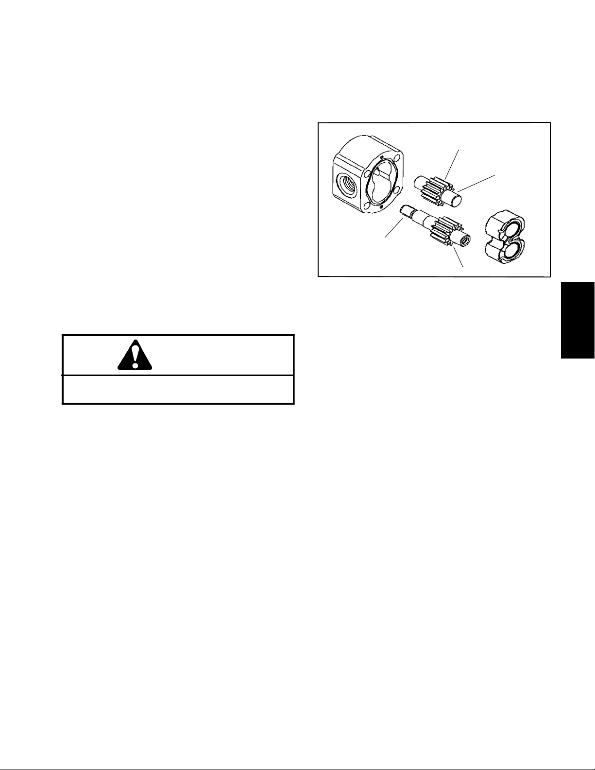
IMPORTANT: Note position of the open and closed
side of the wear plates before removing. Also, identify wear plates (front and rear) for proper reassembly. Do not scribe wear plates.
B. Face of wear plates that are in contact with gears
should be free of wear, roughness or scoring.
C. Thickness of wear plates should be equal.
8. Carefully remove rear wear plate, idler gear, drive
gear and front wear plate from the front plate.
9. Remove and discard back--up gaskets and pressure
seals from wear plates.
IMPORTANT: Make sure not to damage the front
plate counter bore when removing the components
from the front plate.
10.Turn front plate over, with seal side up and carefully
remove the seal, retaining ring, washer and shaft seal.
Discard seals.
11. If necessary, remove anti--cavitation and relief
valves from back plate.
Inspection
1. Remove any nicks and burrs from all parts with
emery cloth.
CAUTION
Use eye protection such as goggles when using
compressed air.
2. Clean all parts with solvent. Dry all parts with compressed air.
3. Inspect drive gears and idler gears for the following
(Fig. 42):
A. Drive gear shaft spline should be free of twisted or
broken teeth.
B. Gear shafts should be free of rough surfaces and
excessive wear at bushing points and sealing areas.
Scoring, rough surfaces or wear on gear shafts indicates need for replacement.
5. Inspect front plate and back plate for damage or
wear.
3
2
1
4
Figure 42
1. Gear shaft spline
2. Gear shaft
3. Gear teeth
4. Gear face edge
Assembly (Fig. 40)
NOTE: When assembling the motor, check the marker
line on each part to make sure the components are properly aligned during assembly (Fig. 41).
1. Lubricate new o--rings, pressure seals, back--up
gaskets and wear plate grooves with a thin coat of petroleum jelly. Lubricate all other internal parts freely with
clean hydraulic oil.
2. Install new shaft seal in front plate. Seal should be
pressed into place until it reaches the bottom of the bore.
3. Install washer and then retaining ring into the groove
of the front plate. Press seal into front plate.
4. Place front plate, seal side down, on a flat surface.
5. Install the backup gaskets into the grooves in the
wear plates. Follow by carefully placing the pressure
seals to the backup gaskets and wear plate.
System
Hydraulic
C. Gear teeth should be free of excessive scoring
and wear. Any broken or nicked gear teeth must be
replaced.
D. Inspect gear face edge for sharpness. Sharp
edges of gears will mill into wear plates and, thus,
must be replaced.
4. Inspect wear plates for the following:
6. Apply a light coating of petroleum jelly to the exposed
side of the front plate.
7. Lubricate the drive gear shaft with clean hydraulic oil.
Insert the drive end of the drive shaft through the front
wear plate with the pressure seal side down and the
open side of the pressure seal pointing to the inlet side
of the motor. Carefully install drive shaft into front plate.
A. Bearing areas should not have excessive wear or
scoring.
Groundsmaster 3505--D Hydraulic SystemPage 4 -- 65
Page 96

8. Lubricate the idler gear shaft with clean hydraulic oil.
Install idler gear shaft into the remaining position in the
front wear plate. Apply a light coating of clean hydraulic
oil to drive and idler gear faces.
9. Install rear wear plate with pressure seal side up and
open side of the pressure seal pointing to the inlet side
of the motor.
14.Apply a light coating of petroleum jelly to the exposed
side of the back plate.
15.Place back plate on assembly. Firm hand pressure
should b e sufficient to engage the dowels.
16.Install the four (4) socket head screws w ith washers
and hand tighten.
10.Apply a light coating of petroleum jelly to new o--rings
and o--ring grooves in the body. Install new o--rings to
the body.
11. Install locating dowels in body. Align marker line on
the body and front plate (Fig. 41).
IMPORTANT: Do not dislodge seals during installation.
12.Gently slide the body onto the assembly using marker line for proper location. Firm hand pressure should be
sufficient to engage the dowel pins.
13.Check to make sure that the surface of the rear wear
plate is slightly below the face of the body. If the wear
plate is not below the body, check assembly for a shifted
pressure seal, backup gasket or o--ring. Correct before
proceeding.
IMPORTANT: Avoid using excessive clamping
pressure on the motor housing to prevent distorting
the housing.
17.Place mounting flange of the motor into a v ise and alternately torque the socket head screws 33 ft--lb (45
N--m).
18.Remove motor from vise.
19.Place a small amount of clean hydraulic oil in the inlet
of the motor and rotate the drive shaft away from the inlet
one revolution. If any binding is noted, disassemble the
pump and check for assembly problems.
20.If removed, install anti--cavitation and relief valves
into back plate. Torque valves 26 ft--lb (35 N--m).
Groundsmaster 3505--DHydraulic System Page 4 -- 66
Page 97

This page is intentionally blank.
System
Hydraulic
Groundsmaster 3505--D Hydraulic SystemPage 4 -- 67
Page 98

Hydraulic Manifold
RIGHT
22
21
22
20
21
16
20
8
14
5
6
8
5
15
13
8
5
6
11
10
9
12
22
21
2
19
20
18
1
23
25
24
3
17
FRONT
1. Hose clamp
2. O-- ring
3. Barb fitting
4. Stud (2 used)
5. Straight hydraulic fitting
6. O-- ring
7. Flange head nut (2 used)
8. O-- ring
9. O-- ring
4
7
Figure 43
10. Straight hydraulic fitting
11. O -- ring
12. Hydraulic hose
13. Hydraulic hose
14. Straight hydraulic fitting
15. O--ring
16. O--ring
17. Hydraulic tube
18. Hydraulic hose
19. Hydraulic manifold
20. O--ring
21. Straight hydraulic fitting
22. O--ring
23. O--ring
o
hydraulic fitting
24. 90
25. O--ring
Groundsmaster 3505--DHydraulic System Page 4 -- 68
Page 99

Removal (Fig. 43)
Installation (Fig. 43)
1. Park machine on a level surface, lower cutting units,
stop engine, engage parking brake and remove key
from the ignition switch.
NOTE: The ports on the manifold are marked for easy
identification of components. Example: BV is the deck
circuit braking valve and P1 is the gear pump connection
port (see Hydraulic Schematic to identify the function of
the hydraulic lines and cartridge valves at each port
location).
2. Thoroughly clean hydraulic manifold before doing
any disassembly.
WARNING
Before disconnecting or performing any work
on the hydraulic system, all pressure in the
system must be relieved. See Relieving Hydraulic System Pressure in the General Information section.
3. Label all hydraulic hoses and fittings for assembly
purposes. Also, mark fittings to allow correct assembly
orientation.
1. Install hydraulic manifold to the frame using Figure
43 as guide. Use labels and marks made during the removal process to properly install hoses and fittings.
2. Make sure hydraulic tank is full. Add correct oil if necessary (see Traction Unit Operator’s Manual).
System
Hydraulic
4. Remove hydraulic manifold from the machine using
Figure 4 3 as guide.
Groundsmaster 3505--D Hydraulic SystemPage 4 -- 69
Page 100

Hydraulic Manifold Service
25 ft--lb
(34 N--m)
120 in--lb
(13.6 N--m)
4
5
3
6
60 in--lb
(6.8 N--m)
35 ft--lb
(47 N--m)
7
45 to 50 ft--lb
(61to68N--m)
2
RIGHT
FRONT
Figure 44
1. Manifold body
2. NWD #4 plug
3. Logic cartridge valve (LC1)
4. Nut
5. Solenoid coil
NOTE: The ports on the manifold are marked for easy
identification of components. Examples: BV is the deck
circuit braking valve and P1 is the gear pump connection
port (see Hydraulic Schematic to identify the function of
the hydraulic lines and cartridge valves at each port
location).
1
6. Solenoid cartridge valve (R1)
7. Braking cartridge valve (BV)
NOTE: The Groundsmaster 3505--D hydraulic man-
ifold uses several zero leak plugs. These plugs have a
tapered sealing surface on the plug head that is designed to resist vibration induced plug loosening. The
zero leak plugs also have an o--ring as a secondary seal.
If zero leak plug removal is necessary, lightly rap the
plug head using a punch and hammer before using an
allen wrench to remove the plug: the impact will allow
plug removal with less chance of damage to the socket
head of the plug.
Groundsmaster 3505--DHydraulic System Page 4 -- 70
 Loading...