

Page 1

Commercial Products
Troubleshooting Guide
Groundsmaster
345/325-D
®
Part No. 96904SL
Page 2
INDEX
1. Product Overview GM 325-D/GM 345
2. Ford VSG-411 Gas Engine (GM 345)
3. Mitsubishi K3D Diesel Engine (GM 325-D)
4. Hydraulic Systems
Hydrostatic Drive Systems
5. Electrical Systems
6. Cutting Unit Drive
7. Cutting Units
Page 3

TORO GM 345 / 325 - D Product Overview
1
Product Overview
GM 300 series Groundsmaster
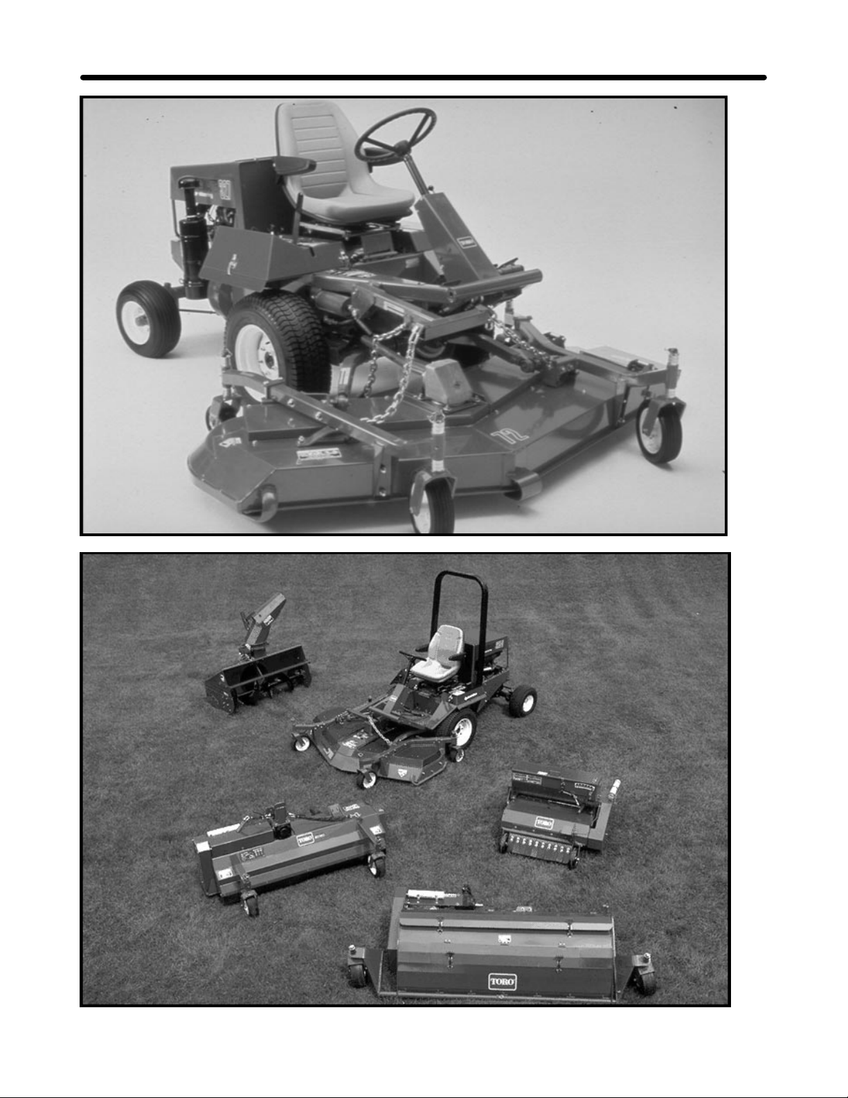
The Groundsmaster 300 series mower is a medium size, maneuverable, commercial rotary with over twenty
years of mowing experience. During those years its design has been continuously improved for optimum
productivity and durability.
GM 345
Features
1. Ford 4 cylinder gas engine (45hp).
2. Sunstrand series M15 inline variable speed hydrostatic drive.
3. Hydraulic power steering and lift functions
4. Available in 2wd.
GM 325-D
Features
1. Mitsubishi 3 cylinder diesel engine (25hp).
2. Sunstrand series M15 inline variable speed hydrostatic drive.
3. Hydraulic power steering and lift functions
4. Available in 2wd and 4wd versions
Options
1. Speed control.
2. 2-Post roll-over Protective Structure (ROPS).
3. 4-Post ROPS with sun roof.
4. Cab with ROPS.
5. Deluxe Seat
Notes
__________________________________________________________________________________________________
__________________________________________________________________________________________________
__________________________________________________________________________________________________
__________________________________________________________________________________________________
__________________________________________________________________________________________________
__________________________________________________________________________________________________
__________________________________________________________________________________________________
__________________________________________________________________________________________________
__________________________________________________________________________________________________
Page 4
Product Overview TORO GM 345
2
Page 5

TORO GM 345 / 325 - D Product Overview
Attachments
1. 72” Side discharge mower deck.
2. 72” Rear discharge mower deck.
3. 72” Guardian Recycler deck.
4. 88” Triflex mower deck.
5. 48” Snowblower
6. Debris blower
7. Aerator
8. Plug pulverizer
9. Aero-seeder
10. V-Plow
11. Flail Mower
3
Notes
__________________________________________________________________________________________________
__________________________________________________________________________________________________
__________________________________________________________________________________________________
__________________________________________________________________________________________________
__________________________________________________________________________________________________
__________________________________________________________________________________________________
__________________________________________________________________________________________________
__________________________________________________________________________________________________
__________________________________________________________________________________________________
Page 6
Ford VSG-411 Gas Engine TORO GM 345
4
Page 7

TORO GM 345 Ford VSG-411 Gas Engine
In this section we will look at some troubleshooting procedures for the Ford Gas Engine.
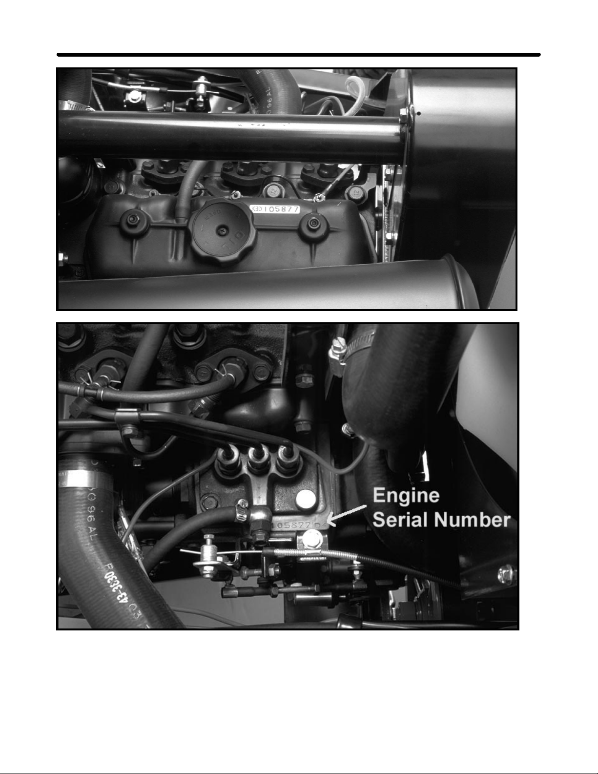
Engine Identification
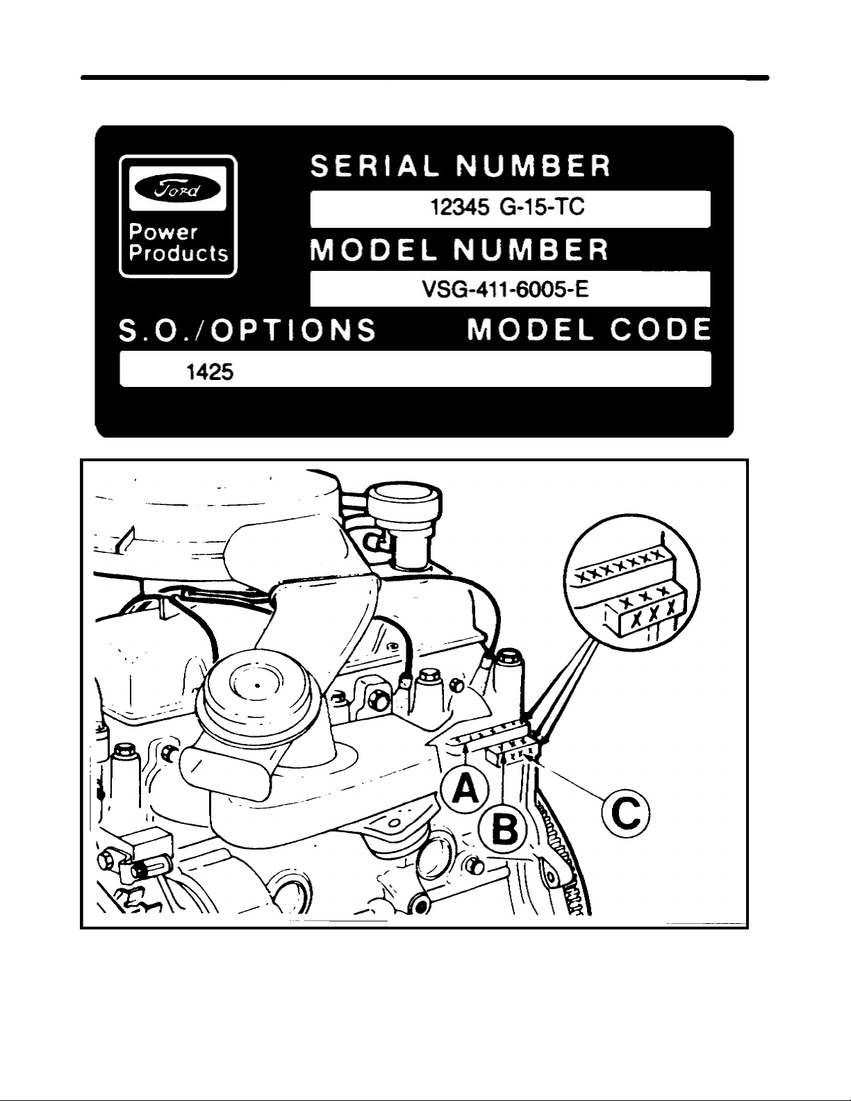
The engine is identified with a decal affixed to the left side of the valve cover.
The decal contains the engine serial number.
The model number and displacement. ( i.e. 411 = 4 cyl 1.1 liter)
The special options (S.O.) number.
The engine is also stamped on the left rear top edge of the block.
This stamping includes:
A - Serial number.
B - Engine Code.
C - Engine build code: (Example 4K26)
• The first number indicates the year.
• The letter indicates the month in alphabetical sequence. ( A January, B February, etc.)
• The last two numbers are the day of the month.
Complaint: Low engine power
Affect:
5
1. Poor cutting unit performance.
2. Poor hill climbing ability.
3. Slow hydraulic response.
4. Slow throttle response.
5. Rough running engine.
Cause:
1. Incorrect engine idle settings. 5. Cracked or bad spark plugs.
2. Misadjusted carburetor linkage. 6. Cracked or broken plug wires.
3. Governor adjustments. 7. Plugged or restricted air filter.
4. Internal engine problem. 8. Spoiled Fuel.
Notes
_______________________________________________________________________________________________________________
_______________________________________________________________________________________________________________
_______________________________________________________________________________________________________________
_______________________________________________________________________________________________________________
_______________________________________________________________________________________________________________
_______________________________________________________________________________________________________________
_______________________________________________________________________________________________________________
_______________________________________________________________________________________________________________
_______________________________________________________________________________________________________________
Page 8
Ford VSG-411 Gas Engine TORO GM 345
6
Page 9

TORO GM 345 Ford VSG-411 Gas Engine
Troubleshooting:
High and Low Idle Checks.
The idle settings are important for the proper operation and long life of the machine.
Affects of incorrect idle speeds:
1. High idle too slow:
• Low power. (engine not running at full speed)
• Slow transport speed. (hydrostatic transmission input shaft speed too slow)
• Poor Quality of cut. (Blade RPM and tip speed too slow)
2. High idle too fast:
• Internal engine damage. (Excessive engine RPM can damage crankshaft and bearings)
• Hydrostatic transmission damage. (insufficient lubrication for high input shaft speeds)
• Engine overheating.
3. Low idle too slow:
• Hydrostatic transmission damage.(lack of lubrication)
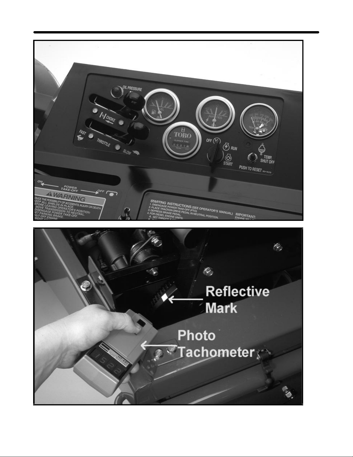
Checking Idle Speeds
1. Run the engine until it reaches normal operating temperature.
2. Move the throttle lever to the low idle position.
• Low idle should be 1500 ± 100.
3. Open the throttle to the high idle position.
• High idle should be 3200 ± 100.
7
NOTE: If high or low idle is incorrect, refer to the Operators manual for correct adjustment procedures.
Notes
_______________________________________________________________________________________________________________
_______________________________________________________________________________________________________________
_______________________________________________________________________________________________________________
_______________________________________________________________________________________________________________
_______________________________________________________________________________________________________________
_______________________________________________________________________________________________________________
_______________________________________________________________________________________________________________
_______________________________________________________________________________________________________________
_______________________________________________________________________________________________________________
Page 10
Ford VSG-411 Gas Engine TORO GM 345
8
Page 11

TORO GM 345 Ford VSG-411 Gas Engine
Correction:
Carburetor linkage adjustment.
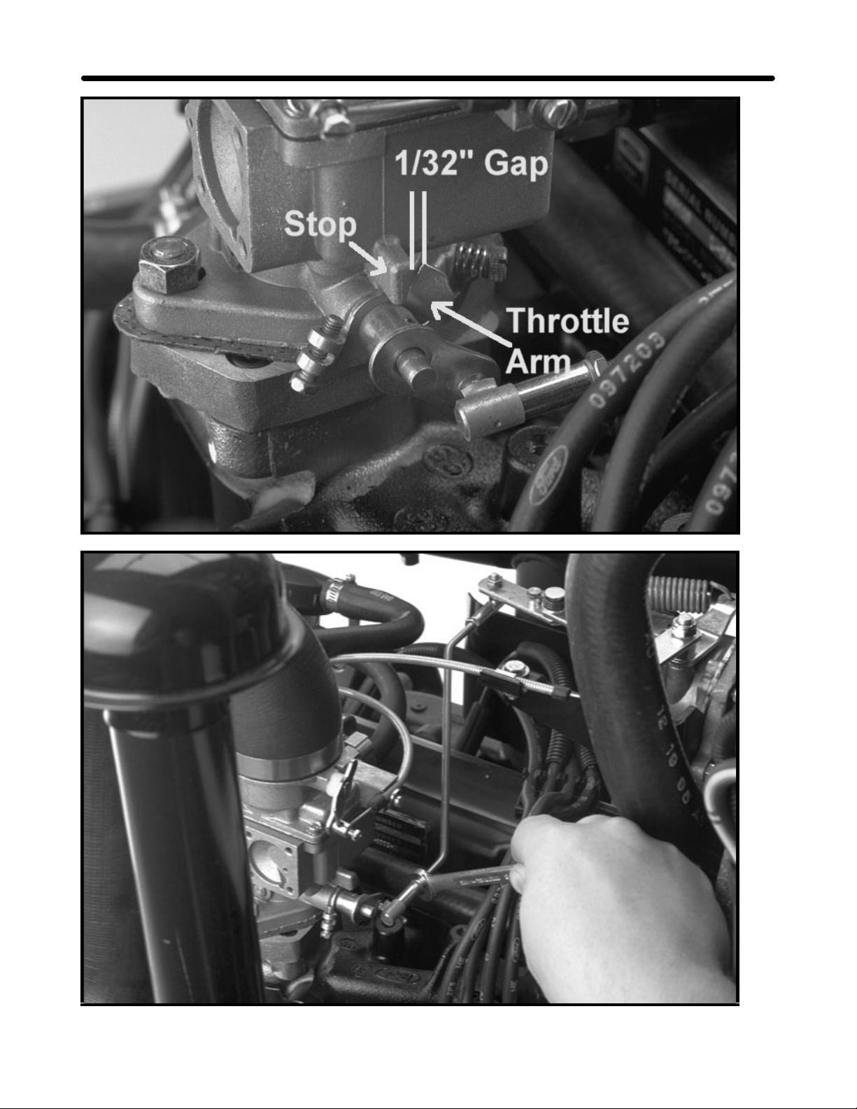
1. With the engine shut off, move the throttle control to the FAST position.
2. Check the gap between the throttle arm and the stop on the carburetor base. The correct gap is 1/32”
(0.78mm).
3. If the gap is not correct adjust the throttle rod by turning the ball joint until the proper gap is attained.
This adjustment insures that the carburetor throttle plate can fully open under a load, but the linkage will not
bottom out against the stop.
9
Notes
_______________________________________________________________________________________________________________
_______________________________________________________________________________________________________________
_______________________________________________________________________________________________________________
_______________________________________________________________________________________________________________
_______________________________________________________________________________________________________________
_______________________________________________________________________________________________________________
_______________________________________________________________________________________________________________
_______________________________________________________________________________________________________________
_______________________________________________________________________________________________________________
Page 12
Ford VSG-411 Gas Engine TORO GM 345
10
Page 13

TORO GM 345 Ford VSG-411 Gas Engine
The final adjustments are made with the engine running. To guard against
possible personal injury, engage the parking brake and keep hands, feet, face
and other parts of the body away from the fan or other moving parts.
Low Idle Adjustment.
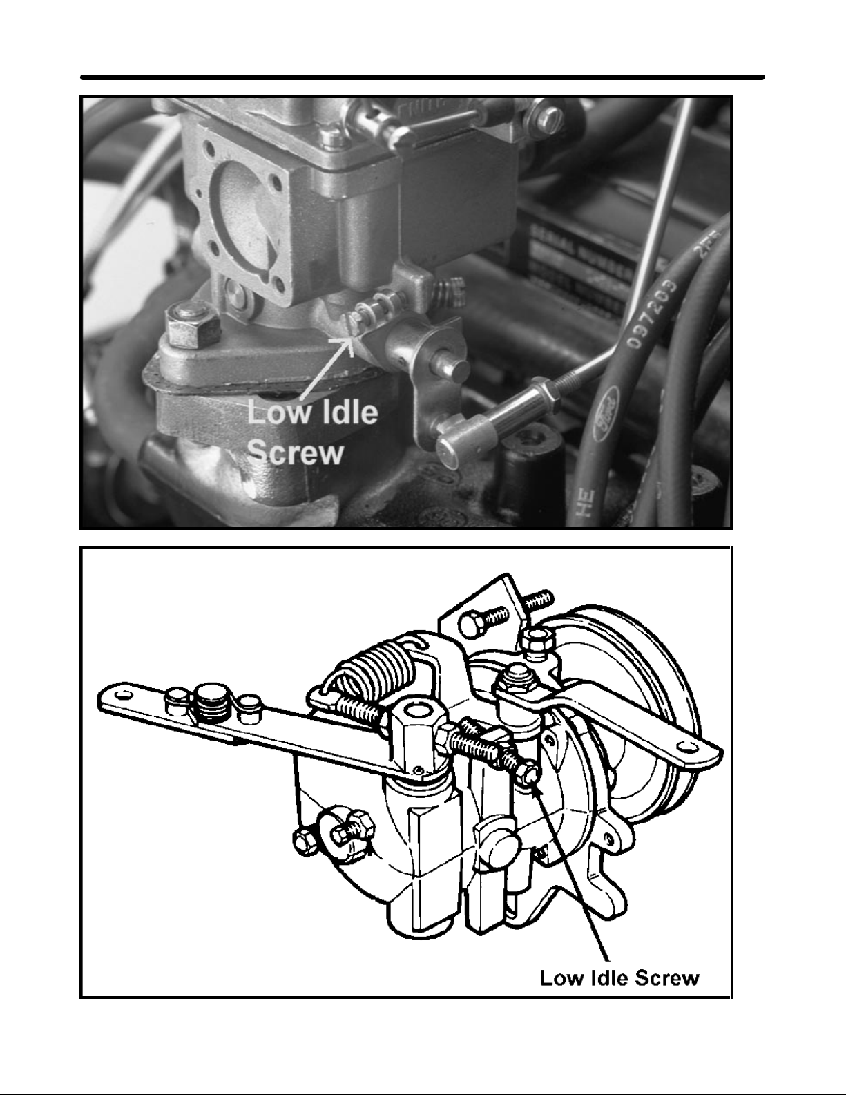
1. Start the engine and move the throttle to the slow position.
2. Manually rotate the throttle arm closed until it contacts the stop.
3. Check the idle speed and adjust carburetor idle speed screw, if necessary to attain 1350 ± 50 rpm.
• This prevents the throttle plate from being able to bottom out in the carburetor barrel.
4. Release the throttle arm, loosen the jam nut on the governor low idle speed screw and adjust it to attain
1500 ± 100 rpm.
• This sets the actual engine idle speed.
11
Notes
_______________________________________________________________________________________________________________
_______________________________________________________________________________________________________________
_______________________________________________________________________________________________________________
_______________________________________________________________________________________________________________
_______________________________________________________________________________________________________________
_______________________________________________________________________________________________________________
_______________________________________________________________________________________________________________
_______________________________________________________________________________________________________________
_______________________________________________________________________________________________________________
Page 14
Ford VSG-411 Gas Engine TORO GM 345
12
Page 15

TORO GM 345 Ford VSG-411 Gas Engine
High Idle Adjustment.
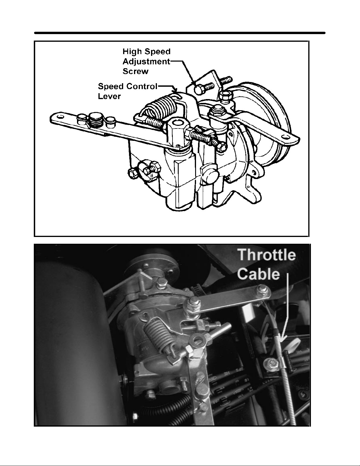
1. Slowly move the throttle to the FAST position until the engine reaches 3200 ± 100. Shut off the engine.
Adjust the high speed adjustment screw until it contacts the speed control lever.
IMPORTANT: Do not overspeed the engine because transmission damaged could occur.
2. If 3200 rpm can not be attained, check the throttle cable adjustment.
• The governor arm must not contact the cable cover when the unit is at high idle.
• If the governor arm contacts the cable, loosen the retaining bolt and move the cable.
3. If the throttle lever on the instrument panel will not stay in the fast position, remove the panel cover and
tighten the nut and capscrew at the base of the throttle lever.
13
Notes
_______________________________________________________________________________________________________________
_______________________________________________________________________________________________________________
_______________________________________________________________________________________________________________
_______________________________________________________________________________________________________________
_______________________________________________________________________________________________________________
_______________________________________________________________________________________________________________
_______________________________________________________________________________________________________________
_______________________________________________________________________________________________________________
_______________________________________________________________________________________________________________
Page 16
Ford VSG-411 Gas Engine TORO GM 345
14
Page 17

TORO GM 345 Ford VSG-411 Gas Engine
15
Anti-Surge Adjustment.
1. Move the throttle rapidly from SLOW to FAST. The engine should not surge, if the engine surges proceed to
step 2.
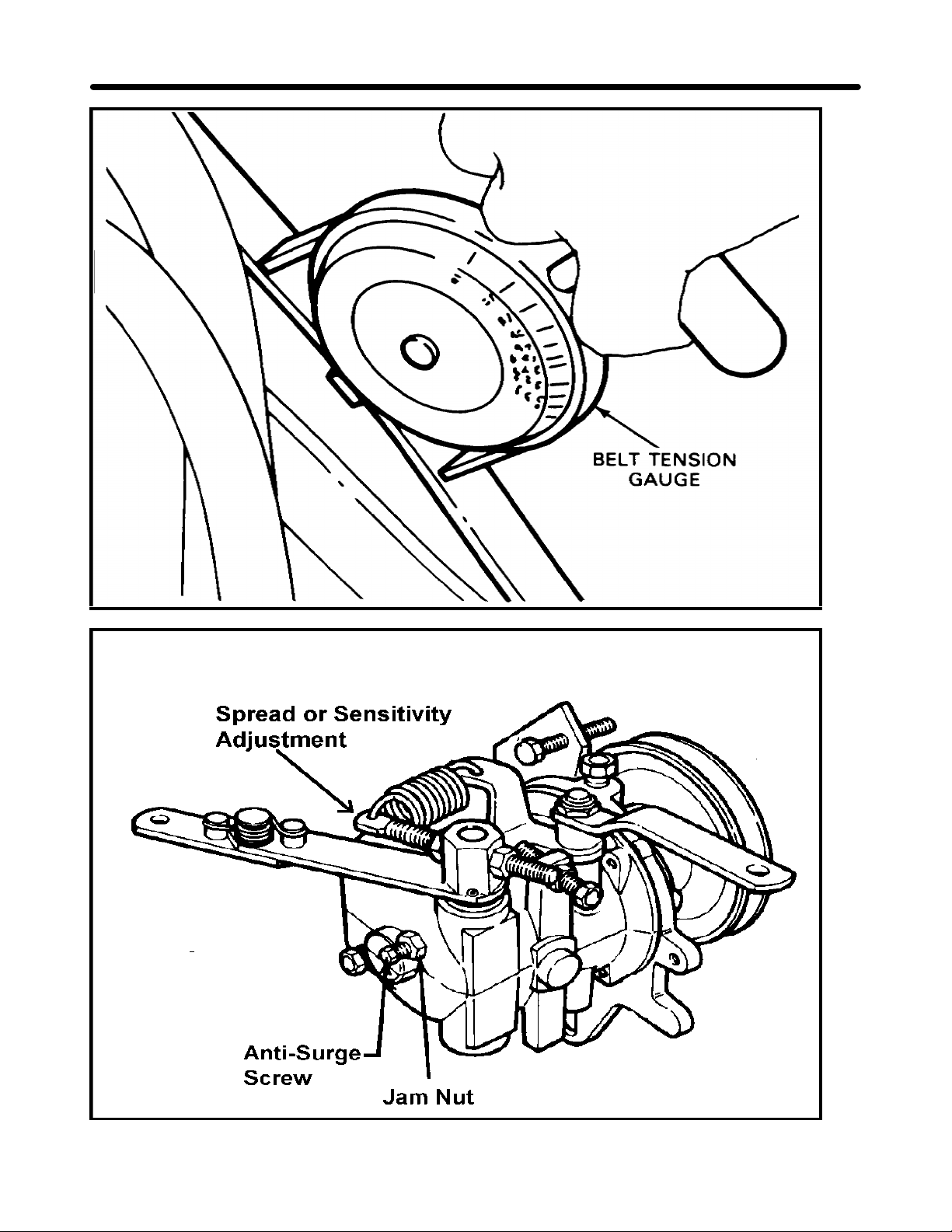
2. Check the V-belts from the engine to the governor pulley and assure that they are tight.
• The belt is adjusted to 45 lbs of tension on a belt gauge for a new belt.
• A used belt is re-tensioned to 28 lbs.
• The replacement belt PN is 67-8510.
3. Loosen the jam nut that retains the anti-surge screw. Rotate the screw clockwise 1/8 of a turn at a time until
the surging stops.
4. Check the low and high idle speed to be sure that there is no change in the initial settings. If the idle speed
has increased, the anti-surge screw has been turned in too far and it must be backed out.
Other things to check when engine surges:
A. Carburetor too rich or lean.
B. Binding in the throttle linkage.
C. Governor worn internally.
Governor Spread or Sensitivity Adjustment.
Governor spread is the difference between the no load governed speed, and the full load speed.
For the governor to work correctly this spread should be 5 to 10 percent.
To check governor spread, check and record the no-load high idle speed and compare this to the loaded high
idle speed.
To increase the spread adjust the adjustment bolt to position the spring farther away from the lever hub. To
decrease the spread position the spring closer to the hub.
Notes
_______________________________________________________________________________________________________________
_______________________________________________________________________________________________________________
_______________________________________________________________________________________________________________
_______________________________________________________________________________________________________________
_______________________________________________________________________________________________________________
_______________________________________________________________________________________________________________
_______________________________________________________________________________________________________________
_______________________________________________________________________________________________________________
_______________________________________________________________________________________________________________
Page 18
Ford VSG-411 Gas Engine TORO GM 345
16
Page 19

TORO GM 345 Ford VSG-411 Gas Engine
17
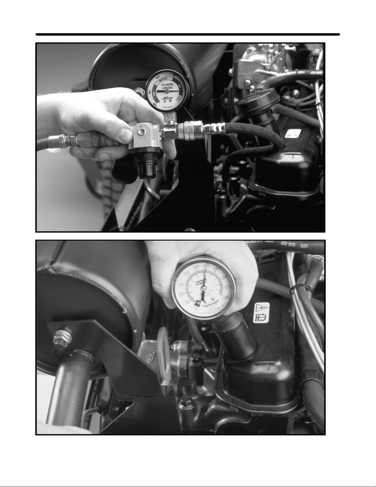
Cylinder Leakage Test.
The cylinder leakage test can locate the following problems:
1. Leaking intake valves.
• Air leaking from carburetor.
2. Leaking exhaust valves.
• Air leaking from muffler.
3. Leaking cylinder head gaskets.
• Air leaking externally by head gasket.
4. Worn piston rings.
• Air leaking from breather or dipstick tube.
NOTE. There will always be some air leakage past the rings. Use the tester gauge to determine the severity of
the leak.
With the engine rotated until the piston is at the top of travel on the compression stroke. The cylinder is filled
with air through the spark plug opening, The leakage tester will display the percentage of air lost when the piston
is at the top part of the compression stroke.
A cylinder leakage of 25 percent or less is acceptable.
Compression Testing.
1. Make sure the batteries are fully charged.
2. Remove all the spark plugs.
3. Set the throttle to high idle and the choke in the wide open position.
4. Install an automotive type (0-300 PSI) compression gauge.
5. Using an auxiliary starting switch, crank the engine (with the ignition switch off) at least five compression
strokes and record the highest reading.
6. Normal compression should read 170 to 185 PSI depending on engine temperature and cranking speed.
7. Repeat the test on each cylinder.
If one or more cylinders read low, and a cylinder leakage tester is not available, squirt approximately one
tablespoon of engine oil on top of the pistons in the low reading cylinders.
Repeat compression test on these cylinders.
1. If the compression improves considerably, the piston rings are at fault.
2. If the compression does not improve, the valves are sticking or seating poorly.
3. If two adjacent cylinders indicate low compression pressures and squirting oil in the pistons does not
increase the compression, the cause may be a leaking cylinder head gasket between the two cylinders.
Notes
_______________________________________________________________________________________________________________
_______________________________________________________________________________________________________________
_______________________________________________________________________________________________________________
_______________________________________________________________________________________________________________
_______________________________________________________________________________________________________________
_______________________________________________________________________________________________________________
_______________________________________________________________________________________________________________
_______________________________________________________________________________________________________________
_______________________________________________________________________________________________________________
Page 20

Ford VSG-411 Gas Engine TORO GM 345
18
Special tools Helpful Hints
1. Electric tach.
• OTC P/N - OEM1386 or equivalent.
2. Photo tach.
• OTC P/N - OEM1057 or equivalent.
3. Belt tension gauge
• OTC P/N - OEM1294 or equivalent
4. Cylinder leakage tester.
• OTC P/N - TOR4075 or equivalent.
5. Compression tester.
• 0 - 300 psi.
• OTC P/N - OEM1072, OEM 1073 or equivalent.
1. All engine RPM checks should be performed
with the engine warm.
2. Governor oil is the same oil as is used in the
crankcase
3. Cylinder leakage can identify the location and
the extent of an internal engine problem
• Cylinder leakage of 25 percent or less is
acceptable
4. When checking engine compression the throttle
and the choke must be fully open to insure an
accurate reading
5. Normal engine compression at cranking speed
is 185 PSI.
6. The actual compression reading is not as
important as the relationship between all the
cylinder readings.
7. Part Numbers
• Engine oil filter, Motorcraft P/N FL.400-A.
• Fuel filter, Motorcraft P/N FG795A.
• Air filter Toro P/N 27-7110
Page 21

TORO GM 345 Ford VSG-411 Gas Engine
Review Questions
19
1. Proper high idle setting is:
a. 2800 ± 50 RPM
b. 3200 ± 100 RPM
c. 3000 ± 25 RPM
d. 1500 ± 100 RPM
2. The final high idle adjustment is made at the
carburetor.
a. True
b. False
3. The recommended compression gauge is:
a. 0 - 100 PSI
b. 0 - 200 PSI
c. 0 - 300 PSI
d. 200 - 400 PSI
4. Normal engine compression is:
a. 100 PSI
b. 205 PSI
c. 185 PSI
d. 415 PSI
5. Adding oil to a cylinder with a bad intake valve
will increase the compression reading of the
cylinder.
a. True
b. False
6. When performing a leakage test, air leaking from
the breather indicates :
a. Leaking intake valve.
b. Leaking exhaust valve.
c. Leaking head gasket.
d. A normal situation
Notes
_______________________________________________________________________________________________________________
_______________________________________________________________________________________________________________
_______________________________________________________________________________________________________________
_______________________________________________________________________________________________________________
_______________________________________________________________________________________________________________
_______________________________________________________________________________________________________________
_______________________________________________________________________________________________________________
_______________________________________________________________________________________________________________
_______________________________________________________________________________________________________________
Page 22
Mitsubishi K3D Diesel Engine TORO GM 325-D
20
Page 23

TORO GM 325-D Mitsubishi K3D Diesel Engine
In this section we will look at some troubleshooting procedures for the Mitsubishi Diesel Engine.
Engine Identification
The engine model number and serial number is listed on a decal on the valve cover.
The engine serial number is also stamped on the injection pump mounting surface.
Complaint: Low engine power
Affect:
1. Poor cutting unit performance.
2. Poor hill climbing ability.
3. Slow hydraulic response.
4. Slow throttle response.
5. Rough running engine.
Cause:
1. Incorrect engine idle settings.
2. Fuel injection problems.
• Incorrect injection timing.
• Incorrect injector spray pattern.
3. Internal engine problem.
4. Poor or contaminated fuel.
5. Restricted air filter or intake.
21
Notes
________________________________________________________________________________________________________________
________________________________________________________________________________________________________________
________________________________________________________________________________________________________________
________________________________________________________________________________________________________________
________________________________________________________________________________________________________________
________________________________________________________________________________________________________________
________________________________________________________________________________________________________________
________________________________________________________________________________________________________________
________________________________________________________________________________________________________________
Page 24
Mitsubishi K3D Diesel Engine TORO GM 325-D
22
Page 25

TORO GM 325-D Mitsubishi K3D Diesel Engine
23
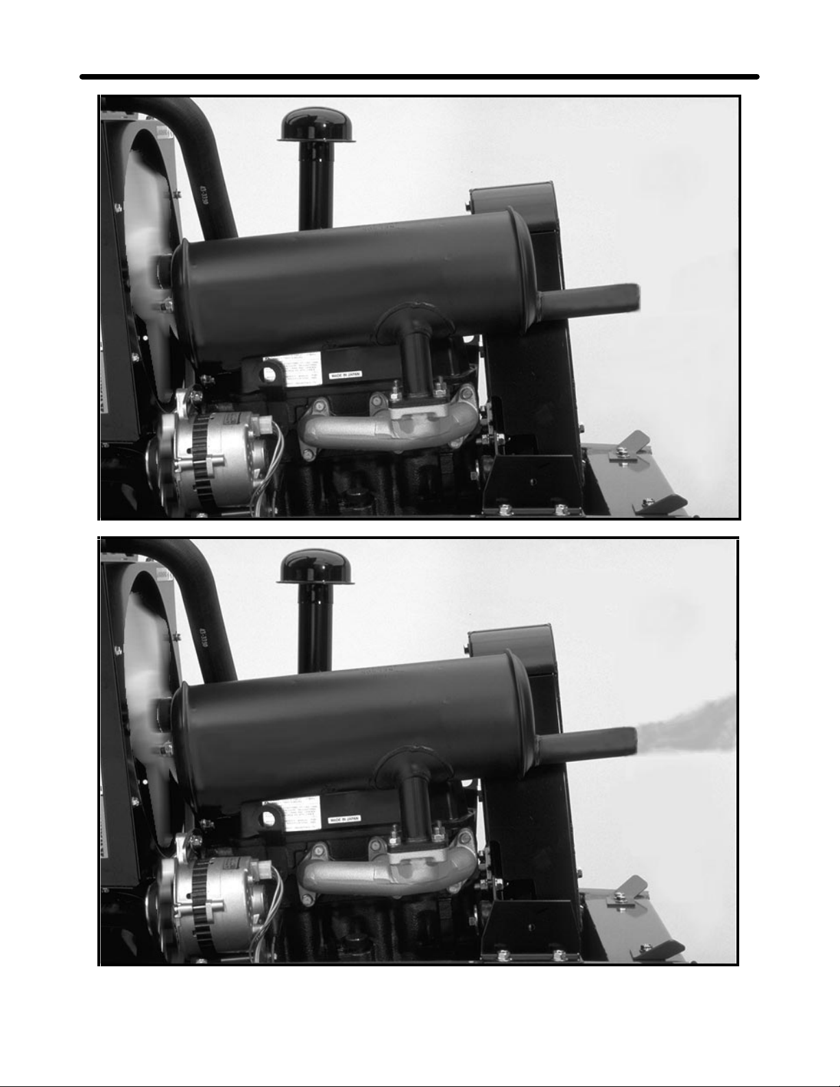
Analyzing Diesel Exhaust Smoke.
The exhaust from a diesel engine can provide information about the running condition of the engine. A normally
operating engine will have exhaust that is clear to a slight brownish/gray color.
1. Black Smoke.
• Insufficient air.
(Plugged or dirty air filter)
• Excessive fuel.
(Leaking injection nozzles)
(Over fueled injection pump setting)
• Engine Overloaded.
(Excessive load on engine)
2. Blue Smoke.
• High engine oil consumption.
(Worn rings or valve guides)
(Plugged crankcase breather)
3. White Smoke.
• Water in combustion chamber.
(Leaking head gasket)
(Cracked cylinder head or cylinder wall)
White smoke can also be caused by the following:
• Incorrect injection timing.
• Low compression.
(Incomplete combustion)
• Low cylinder temperature.
(Faulty glow plugs)
(low ambient air temperature)
Note: White smoke may dissipate when engine warms up.
Notes
________________________________________________________________________________________________________________
________________________________________________________________________________________________________________
________________________________________________________________________________________________________________
________________________________________________________________________________________________________________
________________________________________________________________________________________________________________
________________________________________________________________________________________________________________
________________________________________________________________________________________________________________
________________________________________________________________________________________________________________
________________________________________________________________________________________________________________
Page 26
Mitsubishi K3D Diesel Engine TORO GM 325-D
24
Page 27

TORO GM 325-D Mitsubishi K3D Diesel Engine
25
Troubleshooting
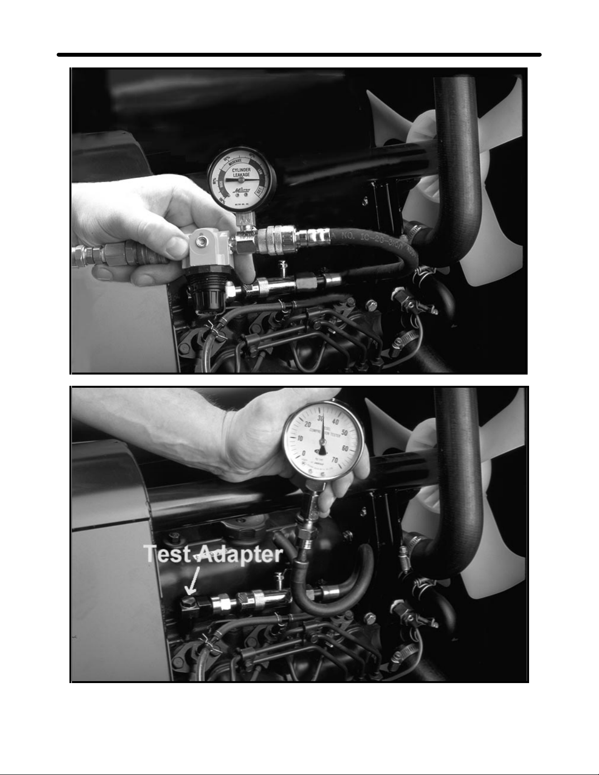
Cylinder Leakage Test.
A cylinder leakage test may be performed if the test equipment is available.
The leakage test can locate:
1. Leaking intake valve.
• Air leaking from the air filter or intake manifold.
2. Leaking exhaust valve.
• Air leaking from the muffler.
3. Piston rings not sealing properly.
• Air leaking from crankcase breather or dipstick tube.
(NOTE: there will always be some leakage past the rings)
With the engine rotated until the piston is at the top of the travel on the compression stroke. The cylinder is filled
with air through the glow plug opening. The leakage tester will display the percentage of air lost, when the piston
is at the top part of the compression stroke.
A cylinder leakage of 25 percent or less is acceptable.
Compression Testing.
1. Make sure the battery is fully charged.
2. Remove the glow plugs from all three cylinders.
3. Hold the fuel shut off lever in the closed position to stop the fuel delivery during the compression test.
• This will prevent wash-down of the cylinders and inaccurate readings.
4. Crank the engine with the starter motor until you get a stable gauge reading. (4 or 5 pulses)
5. If the pressure is less than 455 psi (32 kg/cm²) it will be necessary to find the cause of the low compression.
6. The difference between cylinders should be no more than 36 psi (2.5 kg/cm²).
IMPORTANT: DO NOT put oil into the combustion chamber before performing a compression test.
Damage may result because of hydraulic forces acting upon the piston and the connecting rod.
Notes
________________________________________________________________________________________________________________
________________________________________________________________________________________________________________
________________________________________________________________________________________________________________
________________________________________________________________________________________________________________
________________________________________________________________________________________________________________
________________________________________________________________________________________________________________
________________________________________________________________________________________________________________
________________________________________________________________________________________________________________
________________________________________________________________________________________________________________
Page 28

Mitsubishi K3D Diesel Engine TORO GM 325-D
26
Page 29

TORO GM 325-D Mitsubishi K3D Diesel Engine
Troubleshooting:
High and Low Idle Checks.
The idle settings are important for the proper operation and long life of the machine.
Affects of incorrect idle speeds:
1. High idle too slow.
• Low power. (Engine not running at full speed)
• Slow transport speed. (Hydrostatic transmission input shaft speed too slow)
• Poor Quality of cut. (Blade RPM and tip speed too slow)
2. High idle too fast.
• Internal engine damage. (Excessive engine RPM can damage crankshaft and bearings)
• Hydrostatic transmission damage. (insufficient lubrication for high input shaft speeds)
• Engine overheating.
3. Low idle too slow.
• Hydrostatic transmission damage.(lack of lubrication)
Checking Idle Speeds
1. Run the engine until it reaches normal operating temperature.
2. Move the throttle lever to the low idle position.
• Low idle should be 1500 ± 50.
3. Open the throttle to the high idle position.
• High idle should be 3145 - 3200.
27
Note: if the high and low idle is incorrect, refer to the Operators Manual for the correct adjustment procedures
Notes
________________________________________________________________________________________________________________
________________________________________________________________________________________________________________
________________________________________________________________________________________________________________
________________________________________________________________________________________________________________
________________________________________________________________________________________________________________
________________________________________________________________________________________________________________
________________________________________________________________________________________________________________
________________________________________________________________________________________________________________
________________________________________________________________________________________________________________
Page 30

Mitsubishi K3D Diesel Engine TORO GM 325-D
28
Page 31

TORO GM 325-D Mitsubishi K3D Diesel Engine
29
Injection Nozzles.
The diesel engine requires that the fuel be sprayed into the combustion chamber, at a precise point in the
compression stroke. The point at which this fuel injection occurs is the injection timing. If the nozzle is defective,
damaged, or adjusted incorrectly, the injection timing can be affected. This can cause hard starting, low power
output, excessive smoke or engine knocking.
IMPORTANT: Always use fresh filtered fuel in the nozzle tester. Use of dirty fuel can damage the
precision parts of the injector nozzle.
Injection nozzle tests:
The nozzle tester forces fuel from the nozzle under extremely high pressure.
Always point the nozzle away from your self and any other personnel.
To prevent possible injury always wear safety glasses.
1. Pressure test.
The injection nozzle is connected to the nozzle tester and the nozzle opening (Cracking) pressure is
measured. The pressure at which the injection nozzle opens has a direct effect on the injection timing and
the fuel spray pattern.
• Minimum opening pressure 120 kg/cm² (1700 psi).
Maximum opening pressure 130 kg/cm² (1850 psi).
• Nozzle opening pressure can be adjust by adding or removing shims.
2. Chatter Test.
With the nozzle connected to the nozzle tester, pump the tester slowly, the nozzle will open and close rapidly
(Chatter).
• The chatter test checks the ability of the nozzle to open and close at a high rate of speed.
• A nozzle that does not chatter, may be the result of binding or a bent nozzle.
Notes
________________________________________________________________________________________________________________
________________________________________________________________________________________________________________
________________________________________________________________________________________________________________
________________________________________________________________________________________________________________
________________________________________________________________________________________________________________
________________________________________________________________________________________________________________
________________________________________________________________________________________________________________
________________________________________________________________________________________________________________
________________________________________________________________________________________________________________
Page 32

Mitsubishi K3D Diesel Engine TORO GM 325-D
30
Page 33

TORO GM 325-D Mitsubishi K3D Diesel Engine
1. Nozzle Leakage Test.
• The leakage test checks the nozzle tip for proper sealing.
• A leaking nozzle should be repaired or replaced.
2. Operate the pump until 1500 psi (108 kg/cm²) is reached, maintain this pressure.
3. Check the nozzle end.
• If the nozzle end is dry or a slight film of fuel is present, the nozzle is OK.
• If a drop of fuel forms or the nozzle drips fuel, the nozzle must be serviced or replaced.
31
Notes
________________________________________________________________________________________________________________
________________________________________________________________________________________________________________
________________________________________________________________________________________________________________
________________________________________________________________________________________________________________
________________________________________________________________________________________________________________
________________________________________________________________________________________________________________
________________________________________________________________________________________________________________
________________________________________________________________________________________________________________
________________________________________________________________________________________________________________
Page 34

Mitsubishi K3D Diesel Engine TORO GM 325-D
32
Page 35

TORO GM 325-D Mitsubishi K3D Diesel Engine
1. Nozzle spray Test.
The ability of the nozzle to correctly atomize the fuel can be checked by performing a nozzle spray test.
Pump the nozzle tester and watch the spray pattern.
• A solid stream or large droplets indicates a faulty nozzle.
• Fuel should be well atomized and in a consistent spray pattern.
Leaking injection nozzles can cause:
1. Hard starting.
2. Excessive smoke.
3. Low power.
4. Engine knocking.
5. Injection pump damage.
6. Internal engine damage.
33
Notes
________________________________________________________________________________________________________________
________________________________________________________________________________________________________________
________________________________________________________________________________________________________________
________________________________________________________________________________________________________________
________________________________________________________________________________________________________________
________________________________________________________________________________________________________________
________________________________________________________________________________________________________________
________________________________________________________________________________________________________________
________________________________________________________________________________________________________________
Page 36

Mitsubishi K3D Diesel Engine TORO GM 325-D
34
Page 37

TORO GM 325-D Mitsubishi K3D Diesel Engine
35
Glow Plug Testing.
The diesel engine requires glow plugs to warm the combustion chamber to assist in starting. Evidence of faulty
glow plugs includes: hard starting, excessive smoke, or engine knocking.
There are several ways to test glowplugs.
The resistance of the glow plug can be measured with an Ohmmeter.
Normal resistance is 2 to 3 ohms.
0 ohms indicates a shorted glow plug.
An O.L. reading on the ohmmeter indicates an open circuit in the glow plug.
Another way to test the glow plugs is to remove the plug and connected it to a battery. If the glow plug ends turn
red, the glow plug is working.
A third test is to measure the amperage draw when the glow plug circuit is energized. The operating circuit
should draw 30 amps. (10 amps per glow plug)
Notes
________________________________________________________________________________________________________________
________________________________________________________________________________________________________________
________________________________________________________________________________________________________________
________________________________________________________________________________________________________________
________________________________________________________________________________________________________________
________________________________________________________________________________________________________________
________________________________________________________________________________________________________________
________________________________________________________________________________________________________________
________________________________________________________________________________________________________________
Page 38

Mitsubishi K3D Diesel Engine TORO GM 325-D
36
Special Tools Service Tips
1. Photo tach.
• OTC P/N - OEM1057 or equivalent.
2. Belt tension gauge
• OTC P/N OEM1294 or equivalent
3. Cylinder leakage tester.
• OTC P/N TOR4075 or equivalent.
4. Compression tester.
• 0 - 1000 psi.
• OTC P/N - TOR3003 or equivalent.
•
5. Injection Nozzle Tester
• OTC P/N TOR463610 or equivalent
1. All engine RPM checks should be performed
with the engine warm.
2. Cylinder leakage can identify the location and
the extent of an internal engine problem
• Cylinder leakage of 25 percent or less is
acceptable
3. When checking engine compression the verify
the engine cranking speed to insure an accurate
reading
4. Normal engine compression at cranking speed
is 455 PSI.
5. The actual compression reading is not as
important as the relationship between all the
cylinder readings
6. Part Numbers
• Engine oil filter, Toro P/N 42-9030
• Fuel filter/Water separator
Toro P/N 63-8300
• Fuel pump filter Toro P/N 43-2550
• Air filter Toro P/N 27-7110
Page 39

TORO GM 325-D Mitsubishi K3D Diesel Engine
Study Questions
37
1. Blue exhaust smoke indicates :
a. Excessive fuel
b. water in the combustion chamber.
c. High oil consumption.
d. Excessive engine load.
2. When performing a compression test, add oil to
the pistons before the test
a. True
b. False
3. Proper low idle setting is:
a. 1000 ± 100
b. 1000 ± 50
c. 1500 ±100
d. 1500 ± 50
4. Cylinder leakage of 50 % is acceptable
a. True
b. False
5. Maximum injection nozzle opening pressure is:
a. 1750 psi
b. 1850 psi
c. 1950 psi
d. 2000 psi
6. Injection nozzles should spray fuel in a solid
stream with large droplets.
a. True
b. False
Notes
________________________________________________________________________________________________________________
________________________________________________________________________________________________________________
________________________________________________________________________________________________________________
________________________________________________________________________________________________________________
________________________________________________________________________________________________________________
________________________________________________________________________________________________________________
________________________________________________________________________________________________________________
________________________________________________________________________________________________________________
________________________________________________________________________________________________________________
Page 40

Hydraulics TORO GM 345 / 325-D
38
Hydrostatic Charge Circuit
Page 41

TORO GM 345 / 325-D Hydraulics
39
Hydrostatic Drive and Hydraulic Systems
The drive system on the Groundsmaster 300 series consists of a Sunstrand Series 15, inline hydrostatic
pump and motor assembly. This assemble is connected to a Dana GT-20 axle/differential assembly.
Engine power is transmitted from the engine to the input shaft of the hydrostatic unit. The output of the
hydrostatic unit transmits the power to the pinion shaft, through the differential and to the wheels. The units
brakes are fastened to the outer end of the axle.
Hydrostatic Transmission Operation
Charge Circuit
The charge circuit supplies oil to the hydrostatic circuit and replenishes the oil normally lost through internal
leakage and transmission cooling.
1. Oil from the reservoir is drawn through the oil filter to the charge pump.
2. From the charge pump, the oil is exposed to the charge relief valve which maintains a charge pressure of 70
to 150 psi.
3. The oil then flows to the charge check valves.
4. The check valve that is in the low pressure, (non-driving) side opens and allows oil to flow to the drive loop.
Notes
________________________________________________________________________________________________________________
________________________________________________________________________________________________________________
________________________________________________________________________________________________________________
________________________________________________________________________________________________________________
________________________________________________________________________________________________________________
________________________________________________________________________________________________________________
________________________________________________________________________________________________________________
________________________________________________________________________________________________________________
________________________________________________________________________________________________________________
Page 42

Hydraulics TORO GM 345 / 325-D
40
Drive circuit
Page 43

TORO GM 345 / 325-D Hydraulics
41
Drive Circuit
The drive circuit consists of a variable displacement pump and the hydrostatic motor.
Drive circuit operation.
1. When the traction pedal is depressed the swash plate in the pump rotates and the pump begins to pump.
2. The oil from the pump flows to the hydrostatic motor.
3. The oil flows through the hydrostatic motor and returns to the pump. (The oil flows in a closed loop).
There is a bypass valve located in the drive circuit. When the unit is pushed with the engine off, this valve allows
the oil being forced out of the hydrostatic motor to be directed back to the motor, instead of being forced through
the pump.
Note: Use the bypass valve to move the unit a short distance only, excessive travel can damage the
internal components of the hydrostatic transmission.
Notes
________________________________________________________________________________________________________________
________________________________________________________________________________________________________________
________________________________________________________________________________________________________________
________________________________________________________________________________________________________________
________________________________________________________________________________________________________________
________________________________________________________________________________________________________________
________________________________________________________________________________________________________________
________________________________________________________________________________________________________________
________________________________________________________________________________________________________________
Page 44

Hydraulics TORO GM 345 / 325-D
42
Acceleration valves
Page 45

TORO GM 345 / 325-D Hydraulics
43
Acceleration valves
1. The drive oil from the hydrostatic pump also flows to the acceleration valves.
2. The oil is allowed to flow through the orifice in the valve, until sufficient pressure is created to close the
acceleration valve.
3. Bleeding away some of this initial oil flow allows for a smoother unit start and direction change.
4. The acceleration valves do not serve as the drive circuit relief valve.
5. The 2 wheel drive unit does not have a relief valve.
Relief Valve
The 4 wheel drive unit has an externally mounted relief valve.
The relief valve only regulates the oil pressure in the forward direction.
Notes
________________________________________________________________________________________________________________
________________________________________________________________________________________________________________
________________________________________________________________________________________________________________
________________________________________________________________________________________________________________
________________________________________________________________________________________________________________
________________________________________________________________________________________________________________
________________________________________________________________________________________________________________
________________________________________________________________________________________________________________
________________________________________________________________________________________________________________
Page 46

Hydraulics TORO GM 345 / 325-D
44
Page 47

TORO GM 345 / 325-D Hydraulics
Troubleshooting
To test the hydrostatic system there are several test ports on the hydrostatic unit.
1. Charge pressure test port, (located on the left side rear of the hydrostatic unit, next to the steering and lift
supply line).
2. Forward and reverse drive pressure test ports, (located in the middle section of the hydrostatic unit).
• Forward drive is the RH test port.
• Reverse drive is the LH test port.
• There is also test ports located on the underside of the hydrostatic unit. (Use these test ports for 4WD
units).
Testing charge pressure.
• Remove the test port plug using a 3/16” allen wrench.
• Connect 1000 psi gauge using a 1/8 NPT adapter screwed into the pump.
• Operate engine at 3200 RPM.
• Charge pressure should read 70 - 150 psi.
Low charge pressure
1. Possible causes:
• Plugged hydraulic filter.
• Low engine RPM.
• Defective charge relief valve.
• Defective implement relief valve.
• Worn charge pump.
• Worn drive pump.
• Worn drive motor.
2. Performance results:
• Noisy operation. (Drive circuit not kept full)
• Poor hill performance. (Slows or stops on hills)
• System over heating. (low oil cooler flow)
• Complete drive failure.(unit stops moving)
• Pump or motor failure. (Lack of lubrication)
45
Notes
________________________________________________________________________________________________________________
________________________________________________________________________________________________________________
________________________________________________________________________________________________________________
________________________________________________________________________________________________________________
________________________________________________________________________________________________________________
________________________________________________________________________________________________________________
________________________________________________________________________________________________________________
________________________________________________________________________________________________________________
________________________________________________________________________________________________________________
Page 48

Hydraulics TORO GM 345 / 325-D
46
Drive Pressure Test
Page 49

TORO GM 345 / 325-D Hydraulics
1. Testing drive pressure.
• Remove the test port plug using a 3/16” allen wrench.
• Connect 10,000 psi gauge into the test port using a 3/8 - 24 adapter.
• Chain machine and lock brakes.
• Operate engine at 3200 RPM.
• 2WD, drive pressure should read 4000-4500 psi. (DO NOT exceed 5000 psi)
• 4WD, drive pressure should read 5200 psi.
Low drive pressure. (Charge pressure “OK”)
2. Possible causes.
• Leaking check valves.
• Leaking acceleration valves.
• Leaking bypass valve. (tow valve)
• Worn drive pump.
• Worn drive motor.
3. Performance results.
• Noisy operation. (Oil leaking past check valves or acceleration valves)
• Poor hill climbing performance. (Slows or stops on hills)
• Complete drive failure.(Unit stops moving)
47
Relief Valve
The 4 wheel drive unit has an externally mounted relief valve. To check the relief valve setting, the test gauge
must be connected to the forward test port on the bottom of the hydrostatic pump.
Than test the pressure as usual.
The relief valve is set to limit the drive pressure to 5200 PSI.
Notes
________________________________________________________________________________________________________________
________________________________________________________________________________________________________________
________________________________________________________________________________________________________________
________________________________________________________________________________________________________________
________________________________________________________________________________________________________________
________________________________________________________________________________________________________________
________________________________________________________________________________________________________________
________________________________________________________________________________________________________________
________________________________________________________________________________________________________________
Page 50

Hydraulics TORO GM 345 / 325-D
48
Charge Flow Test
Page 51

TORO GM 345 / 325-D Hydraulics
1. Testing charge flow.
• Connect hydraulic flow meter.
• Operate engine at 3200 RPM.
• Restrict oil flow through flow tester. Should be able to read 1GPM at 700 PSI.
Low charge flow (charge pressure “OK”)
2. Possible causes:
• Leaking implement relief valve.
• Worn drive pump.
• Worn drive motor.
3. Performance results:
• Slow steering response.
• Slow hydraulic response.
• System overheating. (low oil cooler flow)
49
Notes
________________________________________________________________________________________________________________
________________________________________________________________________________________________________________
________________________________________________________________________________________________________________
________________________________________________________________________________________________________________
________________________________________________________________________________________________________________
________________________________________________________________________________________________________________
________________________________________________________________________________________________________________
________________________________________________________________________________________________________________
________________________________________________________________________________________________________________
Page 52

Hydraulics TORO GM 345 / 325-D
50
Page 53

TORO GM 345 / 325-D Hydraulics
51
Steering Circuit
1. Oil from the hydrostatic charge pump flows to the IN port of the steering valve.
2. With the steering wheel in neutral the oil flows out the AUX port to the lift valve.
3. When the steering wheel is turned to the right the AUX port is closed and oil is director out the RT port to the
steering cylinder.
NOTE: The steering valve will not allow oil to flow through it to the lift valve when the steering wheel is being
turned.
Notes
________________________________________________________________________________________________________________
________________________________________________________________________________________________________________
________________________________________________________________________________________________________________
________________________________________________________________________________________________________________
________________________________________________________________________________________________________________
________________________________________________________________________________________________________________
________________________________________________________________________________________________________________
________________________________________________________________________________________________________________
________________________________________________________________________________________________________________
Page 54

Hydraulics TORO GM 345 / 325-D
52
Page 55

TORO GM 345 / 325-D Hydraulics
Cutting Unit Lift Circuit.
1. When the steering wheel is in neutral, oil flows out of the AUX port to the lift valve.
2. When the valve is in neutral oil flows through the valve, to the oil cooler, and then to the reservoir.
3. When the lift valve is actuated, oil is directed to the lift cylinder.
53
Notes
________________________________________________________________________________________________________________
________________________________________________________________________________________________________________
________________________________________________________________________________________________________________
________________________________________________________________________________________________________________
________________________________________________________________________________________________________________
________________________________________________________________________________________________________________
________________________________________________________________________________________________________________
________________________________________________________________________________________________________________
________________________________________________________________________________________________________________
Page 56

Hydraulics TORO GM 345 / 325-D
54
Special Tools Service Tips
1. Hydraulic flow tester kit
• OTC P/N TOR214678 or equivalent
2. Hydraulic pressure test kit.
• OTC P/N TOR47009 or equivalent
1. Hydraulic testing is done with the hydraulic oil
at normal operating temperature.
2. Before testing hydraulics check the system for
the proper oil level and fluid type.
3. Check or replace the hydraulic filter to eliminate
the possibility of a plugged filter.
Page 57

TORO GM 345 / 325-D Hydraulics
Study Questions
55
1. All hydraulic and hydrostatic test should be
conducted with the oil warm.
a. True
b. False
2. Proper engine RPM for hydraulic testing is:
a. 1500 RPM
b. 2000 RPM
c. 3000 RPM
d. 3200 RPM
3. Proper maximum drive pressure for a 2wd unit
is:
a. 2000 PSI
b. 2000 - 3000 PSI
c. 4000 - 4500 PSI
d. 5000 - 5500 PSI
4. The acceleration valves prevent:
a. Abrupt direction change
b. Excessive drive pressure
c. Loss of charge pressure
d. Excessive travel speed
5. Drive pressure is tested with a:
a. 1000 PSI gauge
b. 3000 PSI gauge
c. 5000 PSI gauge
d. 10,000 PSI gauge
6. The steering circuit gets its oil flow before the
cutting unit lift circuit.
a. True
b. False
Notes
_______________________________________________________________________________________________________________
_______________________________________________________________________________________________________________
_______________________________________________________________________________________________________________
_______________________________________________________________________________________________________________
_______________________________________________________________________________________________________________
_______________________________________________________________________________________________________________
_______________________________________________________________________________________________________________
_______________________________________________________________________________________________________________
_______________________________________________________________________________________________________________
Page 58

Electrical Systems TORO GM 345 / 325-D
56
Start Circuit
Position Circuit Make
1 OFF NONE
2 ON B + I + A X + Y
3 START B + I + s
Page 59

TORO GM 345 / 325-D Electrical Systems
57
Electrical System
(GM 345 / 325-D)
The electrical system on the 300 Series Goundsmaster can be broken into the following circuits:
1. Starting/Charging.
2. Safety Interlock.
3. Gauges and warning.
4. Engine.
With a basic understanding of these circuits we can troubleshoot a variety of electrical problems.
System Operation
Start Circuit. (GM 345 Shown, 325-D similar)
1. Power from the battery flows to the (-) terminal of the ammeter.
2. The power flows from the (+) terminal of the ammeter to the ignition switch, terminal (X).
3. The power splits and flows to the seat switch.
4. The power splits again and flows to the neutral switch and PTO switch.
5. When both switches are closed the power can flow to the (B) terminal of the ignition switch.
6. When the switch is turned to the start position power flows from the (B) terminal to the (S) terminal.
7. The power then flows to the starter relay and the relay sends power to the starter which cranks the engine.
8. Power is also directed out of the (I) terminal the temperature relay. From the temperature relay the power is
directed to the D.I.S. ignition module and the carb relay.
Notes
_______________________________________________________________________________________________________________
_______________________________________________________________________________________________________________
_______________________________________________________________________________________________________________
_______________________________________________________________________________________________________________
_______________________________________________________________________________________________________________
_______________________________________________________________________________________________________________
_______________________________________________________________________________________________________________
_______________________________________________________________________________________________________________
_______________________________________________________________________________________________________________
Page 60

Electrical Systems TORO GM 345 / 325-D
58
Interlock Circuit
Position Circuit Make
1 OFF NONE
2 ON B + I + A X + Y
3 START B + I + s
Page 61

TORO GM 345 / 325-D Electrical Systems
Interlock Circuit
Normal Operation.
1. With an operator in the seat and the PTO engaged, the PTO switch opens.
2. Current flows through the seat switch to the “A” terminal of the ignition switch.
3. In the run position, the power flows from the “A” terminal to the “I” terminal.
4. From the “I” terminal power flows to the ignition system.
59
Notes
_______________________________________________________________________________________________________________
_______________________________________________________________________________________________________________
_______________________________________________________________________________________________________________
_______________________________________________________________________________________________________________
_______________________________________________________________________________________________________________
_______________________________________________________________________________________________________________
_______________________________________________________________________________________________________________
_______________________________________________________________________________________________________________
_______________________________________________________________________________________________________________
Page 62

Electrical Systems TORO GM 345 / 325-D
60
Interlock Circuit
Position Circuit Make
1 OFF NONE
2 ON B + I + A X + Y
3 START B + I + s
Page 63

TORO GM 345 / 325-D Electrical Systems
61
PTO Engaged, Operator Not In The Seat.
1. If the operator leaves the seat while the PTO is engaged.
2. Power is interrupted by the seat switch.
3. Current stops flowing to the “A” terminal of the ignition switch.
4. Power is stopped to the ignition module and the engine stops.
Caution: Do not disconnect the safety switches because they are there for the operators protection.
Check the operation of the switches daily to be sure the interlock system is operation correctly. If a
switch is malfunctioning, replace it before operating the machine. Replace the switches every 2 years to
be sure of maximum safety.
Notes
_______________________________________________________________________________________________________________
_______________________________________________________________________________________________________________
_______________________________________________________________________________________________________________
_______________________________________________________________________________________________________________
_______________________________________________________________________________________________________________
_______________________________________________________________________________________________________________
_______________________________________________________________________________________________________________
_______________________________________________________________________________________________________________
_______________________________________________________________________________________________________________
Page 64

Electrical Systems TORO GM 345 / 325-D
62
Page 65

TORO GM 345 / 325-D Electrical Systems
Interlock System Testing
PTO Switch and Traction Neutral Switch Testing.
1. Move the PTO switch to the OFF position.
2. Remove foot from the traction pedal so it is fully released.
3. Rotate the ignition key to start. Engine should crank.
If the engine does not crank, there may be a malfunction in the PTO or Neutral switch.
63
Notes
_______________________________________________________________________________________________________________
_______________________________________________________________________________________________________________
_______________________________________________________________________________________________________________
_______________________________________________________________________________________________________________
_______________________________________________________________________________________________________________
_______________________________________________________________________________________________________________
_______________________________________________________________________________________________________________
_______________________________________________________________________________________________________________
_______________________________________________________________________________________________________________
Page 66

Electrical Systems TORO GM 345 / 325-D
64
Page 67

TORO GM 345 / 325-D Electrical Systems
65
Seat Switch and Traction Neutral Switch Testing
1. Raise off the seat and engage the PTO switch while the engine is running.
2. The engine should stop within 2 seconds.
If the engine stops, the switch is operating correctly.
If the engine does not stop, there is a problem in the seat switch of the PTO switch.
.
1. Raise of the seat and depress the traction pedal with the PTO disengaged.
2. The engine should stop within 2 seconds.
If the engine stops, the switch is operating correctly. If the engine fails to stop, there is a problem in the seat
switch or the traction pedal switch.
Notes
_______________________________________________________________________________________________________________
_______________________________________________________________________________________________________________
_______________________________________________________________________________________________________________
_______________________________________________________________________________________________________________
_______________________________________________________________________________________________________________
_______________________________________________________________________________________________________________
_______________________________________________________________________________________________________________
_______________________________________________________________________________________________________________
_______________________________________________________________________________________________________________
Page 68

Electrical Systems TORO GM 345 / 325-D
66
Page 69

TORO GM 345 / 325-D Electrical Systems
Electrical circuit breaker.
The GM325 electrical system has a 40 amp circuit breaker to protect the electrical system from overload.
If all electric functions are lost, resetting the circuit breaker might remedy the problem.
If the circuit breaker open frequently the source of the problem must be found and repaired.
67
Notes
_______________________________________________________________________________________________________________
_______________________________________________________________________________________________________________
_______________________________________________________________________________________________________________
_______________________________________________________________________________________________________________
_______________________________________________________________________________________________________________
_______________________________________________________________________________________________________________
_______________________________________________________________________________________________________________
_______________________________________________________________________________________________________________
_______________________________________________________________________________________________________________
Page 70

Electrical Systems TORO GM 345 / 325-D
68
Special Tools Helpful Hints
1. Digital volt, ohm meter.
OTC PN. OEM1428 or equivalent
2. Electrical “skin over grease”
OTC PN. TOR50547
1. Interlock switches
• Neutral switch closed with traction pedal in
neutral
• PTO switch closed with PTO disengaged
• Seat switch open with no operator in the seat
2. Unit will start without an operator in the seat, if
the PTO is disengaged and the traction pedal is
in neutral.
3. Unit will run without an operator in the seat, if
the PTO is disengaged and the traction pedal is
in neutral
4. Unit will shut off if operator leaves the seat and
the traction pedal is depressed or PTO is
engaged
5. Interlock switches should be checked daily
6. Interlock switches should be replaced every 2
years or 1500 hrs.
Page 71

TORO GM 345 / 325-D Electrical Systems
Review Questions
69
1. How many interlock switches does the unit
use?
a. 1.
b. 2.
c. 3.
d. 4.
2. The neutral switch is:
a. Open when the traction pedal is depressed
b. Closed when the neutral switch is depressed
3. The unit will start with the operator out of the
seat.
a. True
b. False
c. True (Only if the PTO is disengaged and the
traction pedal is in neutral)
4. The diesel unit has a resetable 40 amp breaker
in the circuit
a. True
b. False
5. The engine should start with the cutting unit in
gear
a. True
b. False
Notes
_______________________________________________________________________________________________________________
_______________________________________________________________________________________________________________
_______________________________________________________________________________________________________________
_______________________________________________________________________________________________________________
_______________________________________________________________________________________________________________
_______________________________________________________________________________________________________________
_______________________________________________________________________________________________________________
_______________________________________________________________________________________________________________
_______________________________________________________________________________________________________________
Page 72

Cutting Unit Drive TORO GM 345 / 235-D
70
Page 73

TORO GM 345 / 325-D Cutting Unit Drive
Attachment Drive (PTO)
GM325/GM345
Pto Operation
1. The power take-off (PTO) system transmits power from the engine to the cutting deck or other implement
attached to the front of the machine.
2. The PTO lever has two positions: ON (engage) and OFF (disengage). To engage the PTO shaft, slowly
push the PTO lever fully forward to the ON position; this will start the implement or cutting unit blades.
Slowly pull the lever backward to the OFF position to stop the implement’s operation. The only time the PTO
lever should be in the ON position is when the implement or cutting unit is down in the operating position
and the operator is in the seat.
71
Notes
_______________________________________________________________________________________________________________
_______________________________________________________________________________________________________________
_______________________________________________________________________________________________________________
_______________________________________________________________________________________________________________
_______________________________________________________________________________________________________________
_______________________________________________________________________________________________________________
_______________________________________________________________________________________________________________
_______________________________________________________________________________________________________________
_______________________________________________________________________________________________________________
Page 74

Cutting Unit Drive TORO GM 345 / 235-D
72
Page 75

TORO GM 345 / 325-D Cutting Unit Drive
Troubleshooting
1. Poor cutting unit performance:
• Drive belt slipping.
• Tighten the drive belt.
• Adjust PTO belt tension spring to 3 3/16 in.(80.96 mm).
2. Drive belt failure:
• Improper belt alignment.
• Align drive belt.
NOTE: See the operators manual or the service manual for the complete adjustment procedure.
73
Notes
_______________________________________________________________________________________________________________
_______________________________________________________________________________________________________________
_______________________________________________________________________________________________________________
_______________________________________________________________________________________________________________
_______________________________________________________________________________________________________________
_______________________________________________________________________________________________________________
_______________________________________________________________________________________________________________
_______________________________________________________________________________________________________________
_______________________________________________________________________________________________________________
Page 76

Cutting Units TORO GM 345/325-D
74
Page 77

TORO GM 345/325-D Cutting Units
Cutting Units
Maintenance and Service
Spindle service
If noisy operation of the cutting unit is encountered and the blade spindles need to be repaired, refer to the
complete repair procedures in the service manual.
The replacement bearing set consists of:
1. The upper and lower bearings races.
2. A snap ring spacer that positions the bearing races in the spindle housing.
3. An outside spacer to set the distance between the bearing races.
4. Two bearings.
5. An inside bearing spacer and an inside spacer ring.
• The inside spacer and the spacer ring position the bearings and set the running clearance.
(NOTE: there in no groove in the shaft that the small ring sets in).
If the spindle does not rotate after assembly, verify that all the spacers and rings are properly installed.
The bearings, races, spacers and snap rings are a matched set and should not be intermixed.
75
IMPORTANT: If a new spindle housing is being used, new bearings and the matched snap ring set must
be installed. Never use the old bearings, spacer, and snap ring with a new spindle housing. By contrast,
use only new bearings with cups and spacer when installing bearings into a used spindle housing that
still has a snap ring installed.
Seal replacement
When replacing the spindle seals be careful to install the seals with the seal lips facing in the correct direction.
72” Recycler Deck
1. The upper seal lip faces inward toward the upper bearing.
2. The lower seal lip faces outward, away from the lower bearing.
72” Rear Discharge & Side Discharge
1. The upper seal lip faces outward away from the upper bearing.
2. The lower seal lip faces outward, away from the lower bearing.
Notes
_______________________________________________________________________________________________________________
_______________________________________________________________________________________________________________
_______________________________________________________________________________________________________________
_______________________________________________________________________________________________________________
_______________________________________________________________________________________________________________
_______________________________________________________________________________________________________________
_______________________________________________________________________________________________________________
_______________________________________________________________________________________________________________
_______________________________________________________________________________________________________________
Page 78

Cutting Units TORO GM 345/325-D
76
Page 79

TORO GM 345/325-D Cutting Units
77
Quality Of Cut
Inspecting and Sharpening Rotary Mower Blades
Rotary mowers cut grass by the blade’s cutting surface impacting against the grass stems at a high velocity. To
assure good quality of cut, the cutting edge of the blade must be kept in a sharp condition. A dull blade will
produce a ragged cut and will require an excessive amount of engine horsepower to rotate the blade through the
grass. The most common cause for rotary mowers not giving a good quality of cut is due to dull cutting edges
and/or bent blades.
Whenever a blade is removed for sharpening:
A. The blade must be checked to assure that it is not bent and that it has the correct attitude in relation to
the housing and ground surface.
B. The blade must be sharpened correctly.
C. The blade balance must be checked each time the blade is sharpened.
D. When installing the blade, it is very important that the blade retaining bolt or nut be tightened to the
correct torque so it will not loosen during operation.
Notes
_______________________________________________________________________________________________________________
_______________________________________________________________________________________________________________
_______________________________________________________________________________________________________________
_______________________________________________________________________________________________________________
_______________________________________________________________________________________________________________
_______________________________________________________________________________________________________________
_______________________________________________________________________________________________________________
_______________________________________________________________________________________________________________
_______________________________________________________________________________________________________________
Page 80

Cutting Units TORO GM 345/325-D
78
Page 81

TORO GM 345/325-D Cutting Units
79
Mismatch cut.
When a mismatch condition occurs the blade tip height should be checked.
It the blade tip height is different, the blades will cut at a different height and the grass will be uneven.
Another quality of cut problem is striping.
Striping can be caused by the mower blades being sharpened too much that the actual blade length is shorter.
This causes a small line of uncut grass to be left between the blades
Inconsistent height of cut.
An inconsistent height of cut can be caused by the cutting deck not staying at the proper height.
The 300 series Groundsmaster has a float position on the cutting unit raise/lower lever. The lever must be in
float while the unit is mowing. If the lever is not in the float position, the cutting unit may not follow the contour of
the ground.
Notes
_______________________________________________________________________________________________________________
_______________________________________________________________________________________________________________
_______________________________________________________________________________________________________________
_______________________________________________________________________________________________________________
_______________________________________________________________________________________________________________
_______________________________________________________________________________________________________________
_______________________________________________________________________________________________________________
_______________________________________________________________________________________________________________
_______________________________________________________________________________________________________________
Page 82

Cutting Units TORO GM 345/325-D
80
Special tools Helpful Hints
1. Blade balancing tool
OTC PN. TOR4029 or equivalent
2. Blade holding fixture
OTC PN. TOR4030 or equivalent
3. Portable bench grinder
OTC PN TOR4031 or equivalent
1. Fill the spindle bearing housing with grease
when replacing the bearings. (This assures that
the upper bearing gets grease when the spindle
is greased).
2. The small inside spacer ring does not have a
groove in the spindle to sit in. Install the ring on
the spindle between the bearings.
3. Mower blade bolt torque is 85 to 100 ft/lbs
4. Bent or twisted blades should be replaced. Do
not straighten.
Page 83

TORO GM 345/325-D Cutting Units
Review Questions
81
1. Bearings and spacers should be replaced as a
set
a. True
b. False
2. The drive belt engagement spring should be
adjusted to a length of:
a. 2 1/4 inches
b. 3 3/16 inches
c. 1 1/2 inches
d. 4 inches
3. The cutting unit raise/lower lever should be in
the neutral position when mowing
a. True
b. False
4. Balancing the blade after sharpening is not
necessary.
a. True
b. False
5. The small spacer ring fits in a groove in the
spindle shaft.
a. True
b. False
6. The PTO drive belt alignment is not adjustable
a. True
b. False
Notes
_______________________________________________________________________________________________________________
_______________________________________________________________________________________________________________
_______________________________________________________________________________________________________________
_______________________________________________________________________________________________________________
_______________________________________________________________________________________________________________
_______________________________________________________________________________________________________________
_______________________________________________________________________________________________________________
_______________________________________________________________________________________________________________
_______________________________________________________________________________________________________________
Page 84

Commercial products
FORM 96-904-SL The Toro Company - 1996 Printed in U.S.A
 Loading...