

Page 1
FormNo.3424-696RevA
Stand-OnSpreader/Sprayer
ModelNo.34215—SerialNo.400000000andUp
Registeratwww.T oro.com.
OriginalInstructions(EN)
*3424-696*A
Page 2
ItisaviolationofCaliforniaPublicResourceCode
Section4442or4443touseoroperatetheengineon
anyforest-covered,brush-covered,orgrass-covered
landunlesstheengineisequippedwithaspark
arrester,asdenedinSection4442,maintainedin
effectiveworkingorderortheengineisconstructed,
equipped,andmaintainedforthepreventionofre.
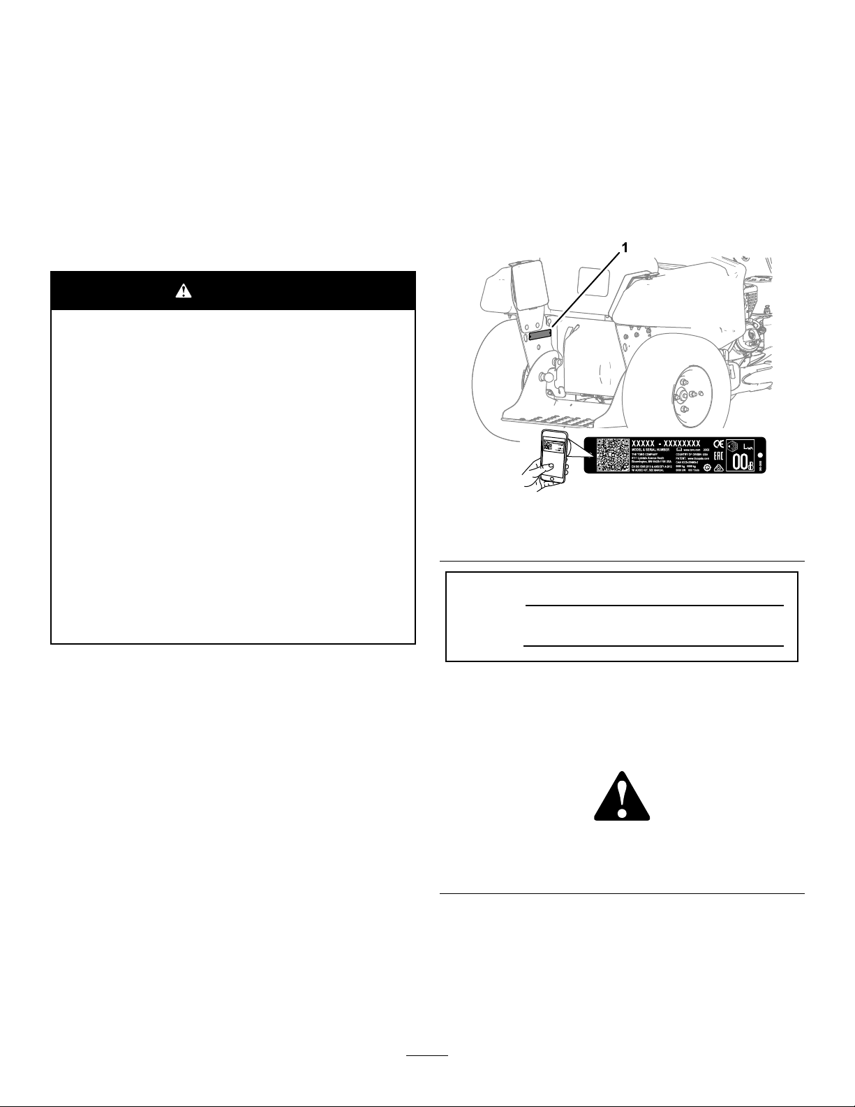
Wheneveryouneedservice,genuineToroparts,or
additionalinformation,contactanAuthorizedService
DealerorToroCustomerServiceandhavethemodel
andserialnumbersofyourproductready.Figure1
identiesthelocationofthemodelandserialnumbers
ontheproduct.Writethenumbersinthespace
provided.
Theenclosedengineowner'smanualissupplied
forinformationregardingtheUSEnvironmental
ProtectionAgency(EPA)andtheCaliforniaEmission
ControlRegulationofemissionsystems,maintenance,
andwarranty.Replacementsmaybeorderedthrough
theenginemanufacturer.
WARNING
CALIFORNIA
Proposition65Warning
Theengineexhaustfromthisproduct
containschemicalsknowntotheStateof
Californiatocausecancer,birthdefects,
orotherreproductiveharm.
Batteryposts,terminals,andrelated
accessoriescontainleadandlead
compounds,chemicalsknownto
theStateofCaliforniatocause
cancerandreproductiveharm.Wash
handsafterhandling.
Useofthisproductmaycauseexposure
tochemicalsknowntotheStateof
Californiatocausecancer,birthdefects,
orotherreproductiveharm.
Important:Withyourmobiledevice,youcan
scantheQRcodeontheserialnumberdecal(if
equipped)toaccesswarranty,parts,andother
productinformation.
g248806
Figure1
1.Locationofthemodelandserialnumbers
ModelNo.
Introduction
Thisstand-onspreadersprayerisintendedforuse
bytrainedoperatorsinresidentialandcommercial
applications.Themachineisprimarilydesignedfor
chemicaldistributionusedforturfcareorsnow/ice
removalatresidentialgrounds,parks,sportselds,
andoncommercialgrounds.
Readthisinformationcarefullytolearnhowtooperate
andmaintainyourproductproperlyandtoavoid
injuryandproductdamage.Youareresponsiblefor
operatingtheproductproperlyandsafely .
YoumaycontactTorodirectlyatwww.T oro.com
forproductsafetyandoperationtrainingmaterials,
accessoryinformation,helpndingadealer,orto
registeryourproduct.
©2018—TheToro®Company
8111LyndaleAvenueSouth
Bloomington,MN55420
SerialNo.
Thismanualidentiespotentialhazardsandhas
safetymessagesidentiedbythesafety-alertsymbol
(Figure2),whichsignalsahazardthatmaycause
seriousinjuryordeathifyoudonotfollowthe
recommendedprecautions.
Figure2
Safety-alertsymbol
Thismanualuses2wordstohighlightinformation.
Importantcallsattentiontospecialmechanical
informationandNoteemphasizesgeneralinformation
worthyofspecialattention.
Contactusatwww.Toro.com.
2
g000502
PrintedintheUSA
AllRightsReserved
Page 3

Contents
Safety.......................................................................4
GeneralSafety...................................................4
SafetyandInstructionalDecals..........................4
Setup........................................................................9
1CheckingtheTireAirPressure.........................9
2CheckingtheEngine-OilLevel.........................9
3CheckingtheTransaxle-FluidLevel.................9
4ConnectingtheBattery..................................10
ProductOverview...................................................10
Controls............................................................11
MachineControls...........................................11
SpreaderControls.........................................13
SprayerControls...........................................14
Specications..................................................16
BeforeOperation.................................................16
BeforeOperationSafety...................................16
PerformingDailyMaintenance..........................17
CheckingtheSafetyInterlockSystem...............17
FuelSpecication.............................................18
UsingStabilizer/Conditioner.............................18
FillingtheFuelTank..........................................18
DuringOperation.................................................19
DuringOperationSafety...................................19
OperatingtheMachine.....................................21
OperatingtheSpreader....................................23
OperatingtheSprayer......................................34
AfterOperation....................................................43
AfterOperationSafety......................................43
CleaningandLubricatingtheSpreader.............43
CleaningtheSprayer........................................44
TransportingtheMachine.................................46
Maintenance...........................................................48
MaintenanceSafety..........................................48
RecommendedMaintenanceSchedule(s)...........49
NotationforAreasofConcern...........................49
Pre-MaintenanceProcedures..............................50
PreparingtheMachine......................................50
Lubrication..........................................................51
LubricatingtheGreaseFittings.........................51
EngineMaintenance...........................................51
ServicingtheAirCleaner..................................51
EngineOilSpecication....................................52
CheckingtheEngine-OilLevel..........................52
ChangingtheEngineOil...................................53
ServicingtheSparkPlug...................................54
ServicingtheSparkArrester.............................55
FuelSystemMaintenance...................................57
CleaningtheFuelSedimentCup......................57
ServicingtheFuelStrainer................................57
ElectricalSystemMaintenance...........................59
ServicingtheBattery.........................................59
RemovingandInstallingtheBattery..................61
Jump-StartingtheMachine...............................62
ServicingtheFuses..........................................62
DriveSystemMaintenance..................................63
CheckingtheAirPressureintheTires...............63
TorquingtheAxleBolts.....................................63
AligningtheFrontWheels.................................64
ServicingtheTransaxle....................................65
ControlsSystemMaintenance.............................66
AdjustingthePatternControlCableforthe
Spreader......................................................66
MaintainingtheChassis.......................................67
CheckingtheMachineforLoose
Hardware......................................................67
MaintainingtheSprayerSystem...........................67
CheckingSprayerSystem................................67
Cleaning..............................................................68
CleaningtheEngineandtheExhaust
SystemArea.................................................68
CleaningtheDebrisfromtheMachine...............68
RemovingtheEngineShroudandCleaning
theCoolingFins............................................68
WasteDisposal.................................................68
Storage...................................................................69
PreparingtheMachineforExtendedor
WinterStorage..............................................69
Troubleshooting......................................................71
Schematics.............................................................75
3
Page 4
Safety
ThefollowinginstructionsarefromANSIstandard
B71.4-2017.
GeneralSafety
Thisproductiscapableofcausingpersonalinjury.
Alwaysfollowallsafetyinstructionstoavoidserious
personalinjury.
Usingthisproductforpurposesotherthanitsintended
usecouldprovedangeroustoyouandbystanders.
•Readandunderstandthecontentsofthis
Operator’sManualbeforestartingtheengine.
•Useappropriatepersonalprotectiveequipment
(PPE)toguardagainstcontactwithchemicals.
Chemicalsubstancesusedinthesprayersystem
maybehazardousandtoxic.
•Donotputyourhandsorfeetnearmoving
componentsofthemachine.
•Donotoperatethemachinewithoutallguards
andothersafetyprotectivedevicesinplaceand
workingonthemachine.
•Keepclearofanydischargeareaofthesprayer
nozzlesandspraydrift.Keepbystandersandpets
asafedistanceawayfromthemachine.
•Keepchildrenoutoftheoperatingarea.Never
allowchildrentooperatethemachine.
•Stopthemachine,shutofftheengine,andremove
thekeybeforelling,emptying,servicing,or
uncloggingthemachine.
Improperlyusingormaintainingthismachinecan
resultininjury .T oreducethepotentialforinjury,
complywiththesesafetyinstructionsandalways
payattentiontothesafety-alertsymbol
meansCaution,Warning,orDanger—personalsafety
instruction.Failuretocomplywiththeseinstructions
mayresultinpersonalinjuryordeath.
Youcanndadditionalsafetyinformationwhere
neededthroughoutthismanual.
Also,gotowww.Toro.comforevenmoresafe
operatingpractices,includingsafetytipsandtraining
materials.
Notalltheattachmentsthatadapttothismachine
arecoveredinthismanual.Refertotheoperator’s
manualprovidedwitheachattachmentforadditional
safetyinstructions.
,which
SafetyandInstructionalDecals
Safetydecalsandinstructionsareeasilyvisibletotheoperatorandarelocatednearanyarea
ofpotentialdanger.Replaceanydecalthatisdamagedormissing.
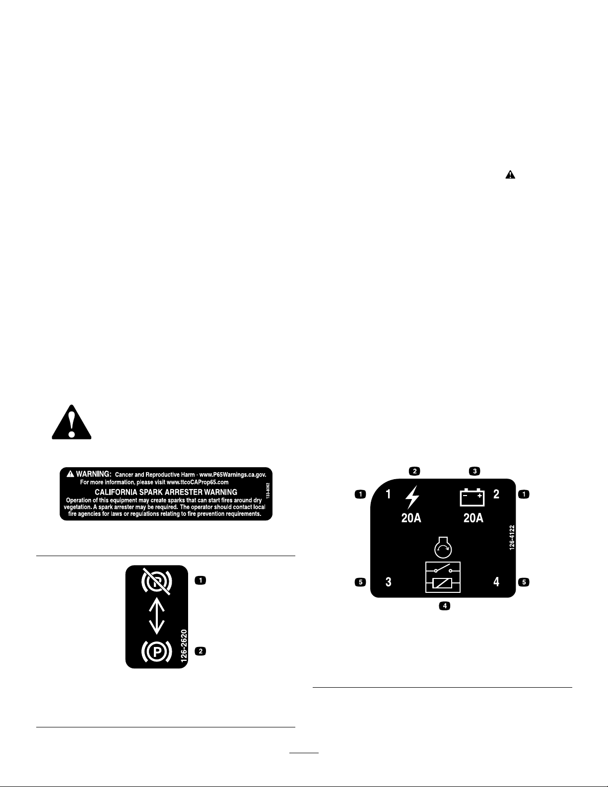
133-8062
126-2620
decal133-8062
decal126-4122
126-4122
1.Fuselocation
2.Main,20A5.Relaylocation
decal126-2620
3.Regulator,20A
4.Startrelay
1.Pullleveruptodisengage
thebrake.
2.Pushleverdownto
engagethebrake.
4
Page 5
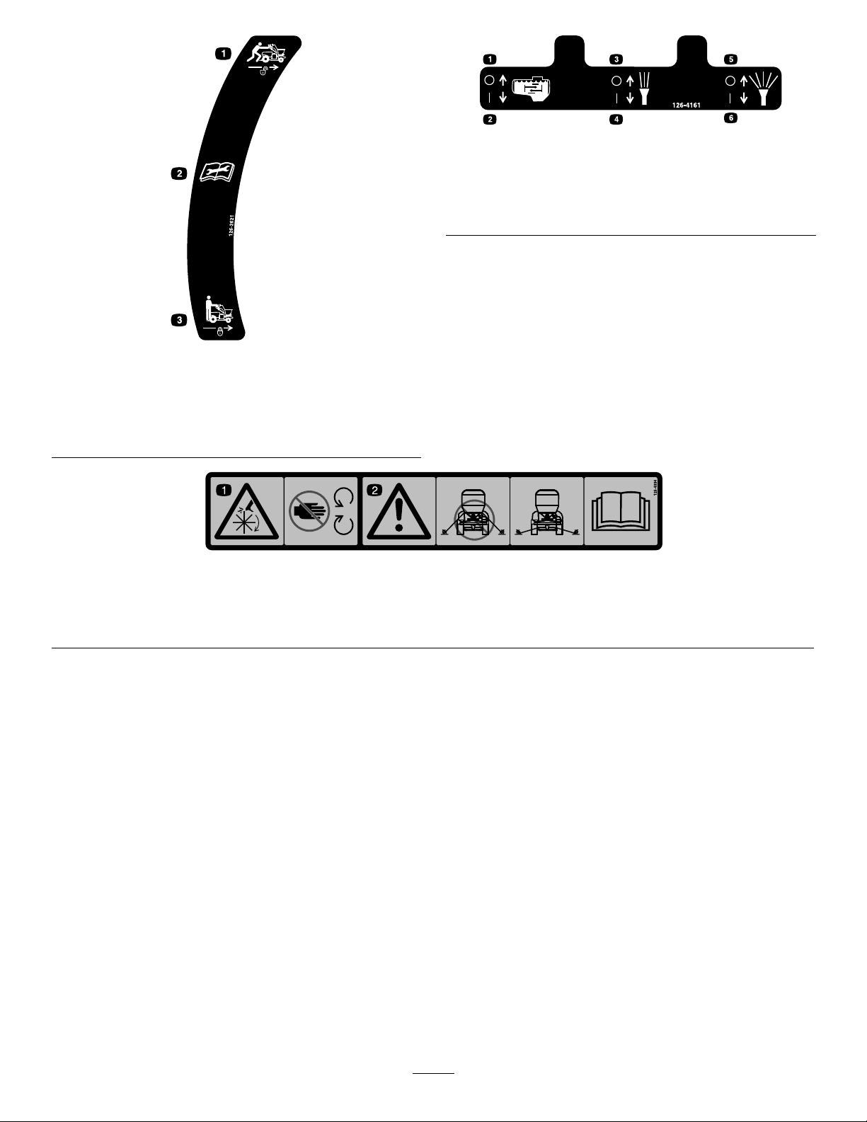
126-2621
1.Unlocktopushmachine.3.Locktodrivemachine.
2.Readtheinstructions
beforeservicingor
performingmaintenance.
decal126-4161
126-4161
1.Agitation-Off4.Narrowspray-On
2.Agitation-On5.Widespray-Off
3.Narrowspray-Off6.Widespray-On
decal126-2621
1.Cutting/dismembermenthazard—keepawayfrommoving
parts.
decal126-4994
126-4994
2.Warning—donotusetheupperfrontlocationsastiedown
points,onlyusethespeciedtie-downpoints;seethe
Operator’sManualforlocation.
5
Page 6
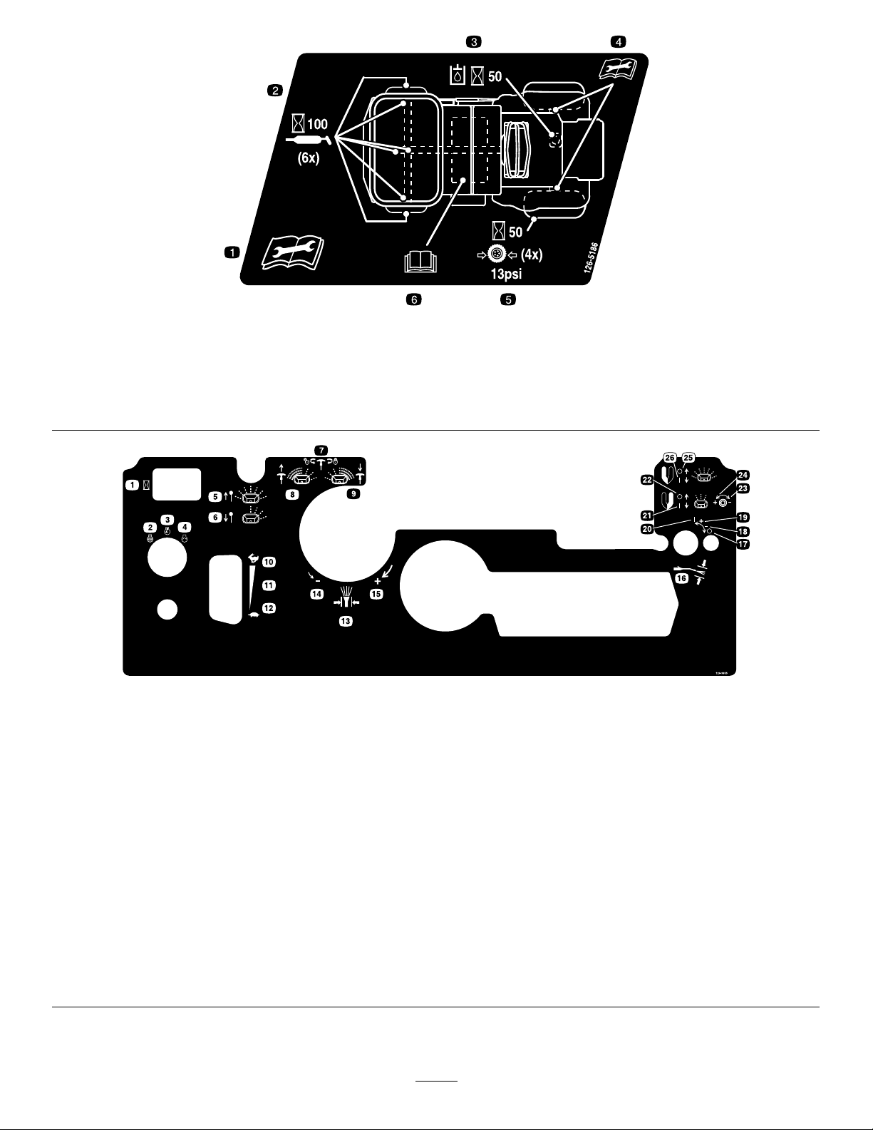
decal126-5186
126-5186
1.ReadtheOperator'sManualbeforeservicingthemachine
orperformingmaintenance.
4.Formoreinformationonservicingtherearaxleshafts,read
theOperator'sManual.
2.Greasethesteeringpivotsevery100hours.5.Checkthetirepressure—90kPa(13psi)every50hours.
3.Checkthehydraulicuidlevelevery50hours.6.ReadtheOperator'sManual.
126-9655
1.Hourmeter
2.Engine—off15.Spraypressure—increase
3.Engine—on
4.Engine—start
5.Deector—pullknobuptoopen18.Spray-wand-pressurecontrol—decrease
6.Deector—pushknobdowntoclose19.Spray-wandpressurecontrol—increase
7.Spreaderpatterncontrol—rotatecounterclockwisetounlock;
rotateclockwisetolock.
8.Spreadpatterncontrol—pullhandleupifheavyonleftside21.Granular-spinnerlever—narrowdistribution-on
9.Spreadpatterncontrol—pushhandledownifheavyonright
side
10.Throttle—fast23.Granular-spinnerknob—narrowdistribution-decrease
11.Continuous-variablesetting24.Granular-spinnerknob—narrowdistribution-increase
12.Throttle-slow
13.Spray-pressurecontrol26.Granular-spinnerlever—widedistribution-on
14.Spraypressure—decrease
16.Spray-wand-pressurecontrol
17.Spray-wand-pressurecontrol—off
20.Spray-wandpressurecontrol—on
22.Granular-spinnerlever—narrowdistribution-off
25.Granular-spinnerlever—widedistribution-off
decal126-9655
6
Page 7

135-2844
1.Fast
2.Slow
3.Neutral
4.Reverse
5.Warning—readtheOperator’sManual;donotoperatethismachineunlessyouaretrained;wearearprotection.
6.Warning—stayawayfrommovingparts;keepallguardsandshieldsinplace;shutofftheengineandremovethekeybefore
performingmaintenance.
7.Warning—shutoffthesprayercontrols,putthemachineinNeutral,engagetheparkingbrake,andshutofftheenginebefore
leavingthemachine.
8.Runover/backoverhazard—donotcarrypassengers;lookbehindyouwhenmovinginreverse.
9.Thrownobjecthazard—keepbystandersaway .
10.Warning—operateacrossslopes,notupanddown;youcanfallifoperatingdownslopes.
11.Causticliquid/chemicalburnandtoxicgasinhalationhazard—wearhandandskinprotection;weareyeandrespiratoryprotection.
12.Warning—usefresh,cleanwaterforrst-aidwashingandrinsingthetank.
13.Neutral
14.Movethesteeringcontrolrighttoturnright.
15.Movethesteeringcontroltothecentertogostraight.
16.Movethesteeringcontrollefttoturnleft.
decal135-2844
7
Page 8

SpreaderSprayerControl
1.Spraypumpswitch—On/Off
2.Solidlight-normalpumpoperation
3.Fastashinglight-pumpmalfunction;seeOperator’smanual.
4.Solidlight-normaloperationofspreadermotorandspeedcontrol.
5.Fastashinglight-spreadermotorand/orspeedcontrolmalfunction;seeOperator’smanual.
Constantslowashinglight-spreadermotorspeedsettinglocked.
6.Granularimpellermotorandspeedcontrol—On/Off;presspushbuttonfast.
7.Granularspeedcontrollock/unlock-On/Off;pressandholdbutton.
8.Speedcontrol—slow
9.Speedcontrol—fast
decalspreadspraycontrol
8
Page 9

Setup
LooseParts
Usethechartbelowtoverifythatallpartshavebeenshipped.
ProcedureDescription
4
MediaandAdditionalParts
Description
Operator'sManual
Key2
Nopartsrequired
1
CheckingtheTireAir Pressure
NoPartsRequired
Qty.
Qty.
–
1
Readbeforeoperatingthemachine.
Startthemachine.
Connectthebattery.
Use
Use
3
Checkingthe Transaxle-FluidLevel
NoPartsRequired
Procedure
Checktheairpressureinthefrontandreartires,and
ifnecessary,addairtotheappropriatepressure;refer
toCheckingtheAirPressureintheTires(page63).
2
CheckingtheEngine-Oil Level
NoPartsRequired
Procedure
Theenginecomeswithoil;checktheengine-oillevel
and,ifnecessary,addtotheappropriatelevel;referto
EngineOilSpecication(page52)andCheckingthe
Engine-OilLevel(page52).
Procedure
Thetransaxlecomeswithuid;checktransaxle-uid
levelintheexpansiontank,andifnecessary,addto
theappropriatelevel;refertoServicingtheTransaxle
(page65).
9
Page 10
4
ConnectingtheBattery
NoPartsRequired
Procedure
1.Removethebatterycoverfromthebatterybox
(Figure3).
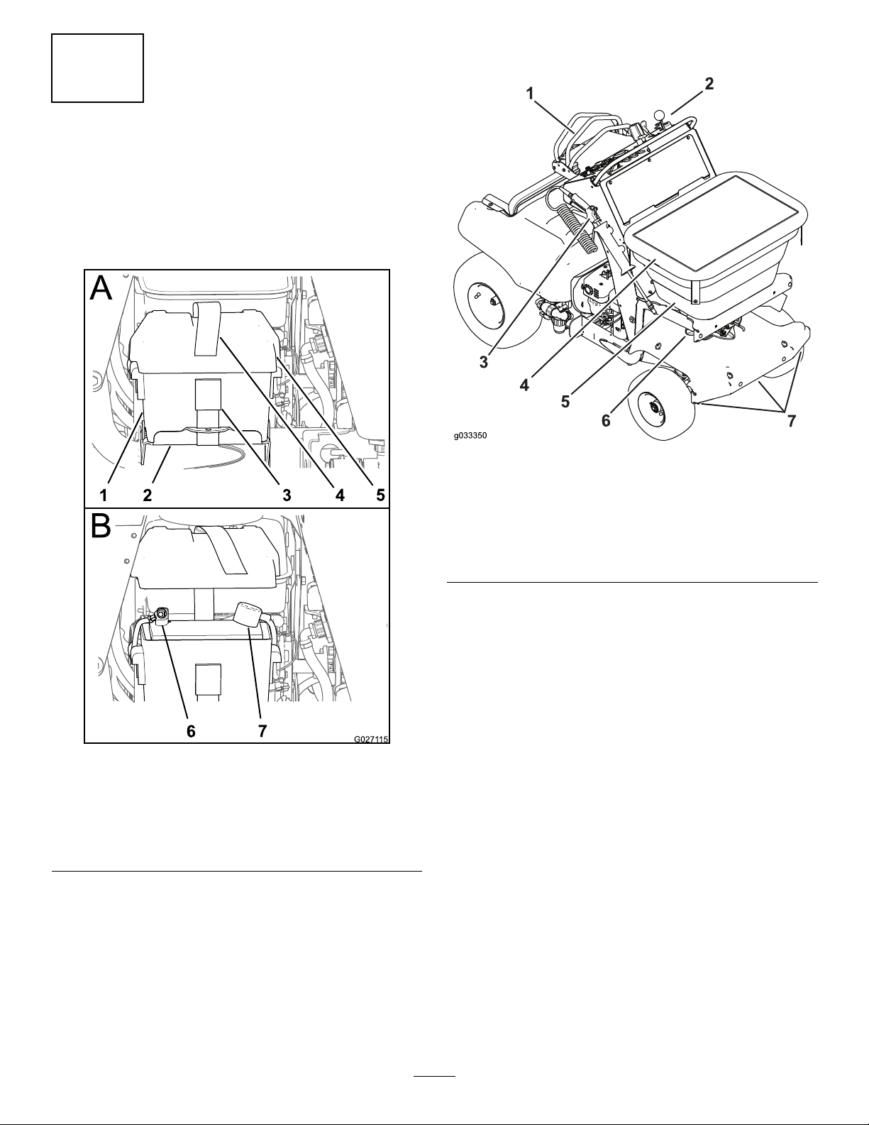
ProductOverview
g033350
Figure4
Figure3
1.Batterybox5.Batterycover
2.Batterysupport6.Negativeterminal
3.Buckle7.Positiveterminal
4.Batterystrap
2.Installthepositive-batterycabletothepositive
(+)batteryterminalwithaangedboltand
angednut(Figure3).
3.Installthenegative-batterycabletothenegative
(–)batteryterminalwithaangedboltand
angednut(Figure3).
4.Installthecoveronthebatteryboxandsecure
thecoverandboxtothebatterytraywiththe
batterystrap(Figure3).
1.Motion/steeringcontrol
2.Engine/spreader—sprayer
controls
3.Spraywand7.Sprayernozzles
4.Hoppercover
g027115
5.Hopper
6.Impeller
10
Page 11
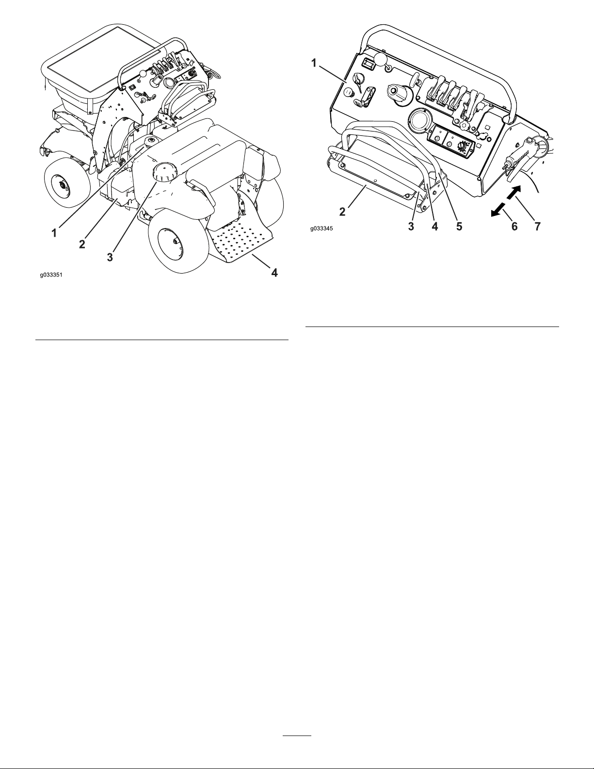
1.Fuel-tankcap
2.Battery
Figure5
3.Sprayer-tankcap
4.Platform
g033345
Figure6
1.Controlconsole5.Frontreferencebar
g033351
2.Steeringcontrol
3.Rearreferencebar
4.Motion-controllever
(Neutralposition)
Motion-ControlLever
6.Reverse
7.Forward
Controls
MachineControls
SteeringControl
Thesteeringcontrolislocatedbehindthecontrol
console(seeFigure6).
•Movethesteeringcontroltotherightorleftto
steerthemachinetotherightorleftrespectively.
•Movingthesteeringcontroltothecenterallows
themachinetosteerstraight.
Themotion-controllever,locatedinthecenterofthe
steeringcontrol,controlstheforwardandreverse
motionofthemachine(seeFigure6).
•Movethemotion-controlleverforwardorbackward
todrivethemachinerespectively.
Note:Themachinespeedisproportionaltothe
amountthatyoumovethemotion-controllever.
•Whenyoumovethemotion-controllevertothe
centerposition,themachineshouldstop.
Note:Whenyoureleasethemotion-controllever,
itshouldreturntotheNEUTRALposition.
Important:Ifthemotion-controlleverdoes
notreturntotheNEUTRALpositionwhenyou
releaseit,contactanAuthorizedService
Dealer.
11
Page 12
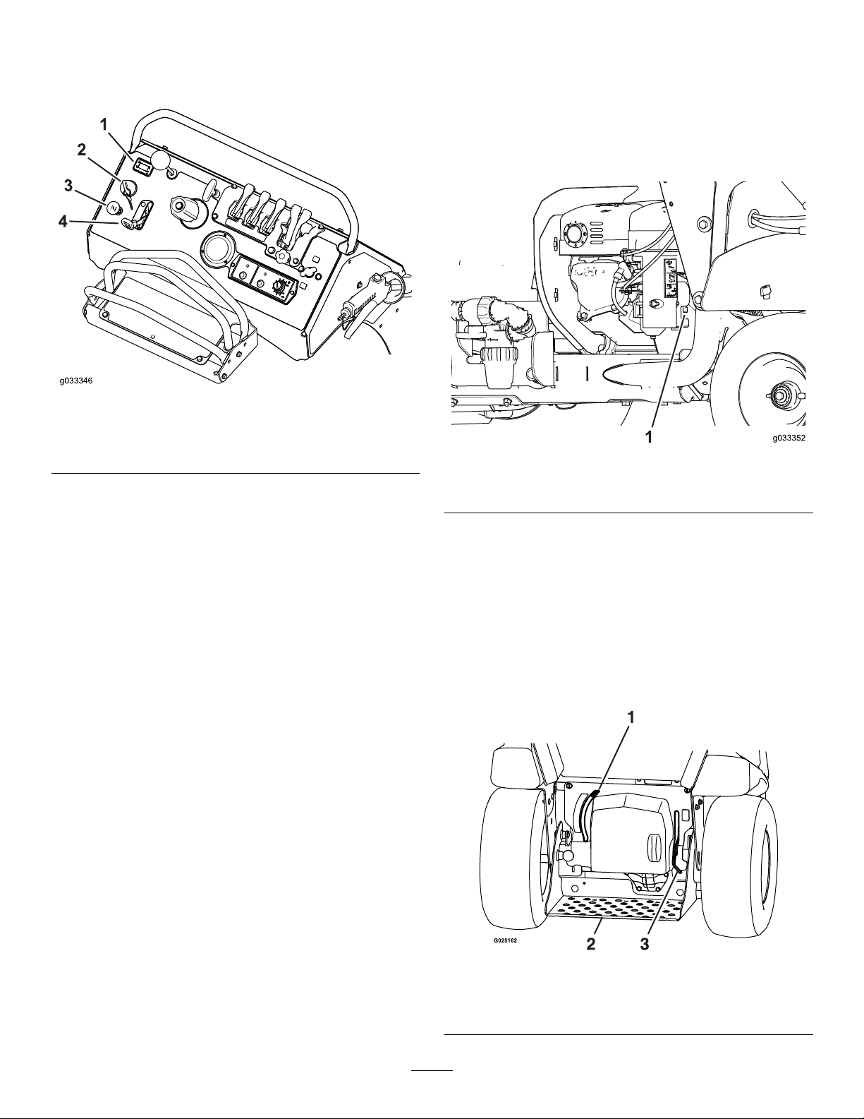
ThrottleControl
Fuel-Shut-OffValve
Thethrottlecontrol(theredlever)islocatedattheleft
sideofthecontrolconsole(Figure7).
Figure7
1.Hourmeter
2.Ignitionswitch4.Throttle
3.Choke
Thefuel-shut-offvalveislocatedatthefront,rightside
oftheenginebelowthefueltank(Figure8).
Note:Closethefuel-shut-offvalvewhenthemachine
isnotusedforafewdays,duringtransporttoand
fromthejobsite,orwhenthemachineisparked
insideabuilding.
g033346
g033352
Figure8
ChokeControl
Thechokecontrolislocatedattheleftsideofthe
controlconsole;youuseittohelpstartacoldengine
(Figure7).
Note:Donotstartorrunawarmenginewiththe
chokeintheONposition.
•Pulluponthechokecontroltosetthechoketo
theONposition.
•Pushdownonthechokecontroltosetthechoke
totheOFFposition.
IgnitionSwitch
Theignitionswitchislocatedattheleftsideofthe
controlconsole(Figure7).
Usetheignitionswitchtostartandshutofftheengine.
Theignitionswitchhasthreepositions,OFF,ONand
START.
Note:Youmustengagetheparkingbraketostart
theengine.
1.Fuel-shut-offvalve(rightsideoftheengine)
Parking-BrakeLever
Theparking-brakeleverislocatedabovetheplatform
ontherightside(Figure9).
•Toengagetheparkingbrake,pushthe
parking-brakeleverdown.
Note:Thebrakeleverengagesaparkingbrake
inthetransaxle.
•Toreleasetheparkingbrake,pulltheleverup.
HourMeter
Thehourmeterislocatedabovetheignitionswitchat
theleftsideofthecontrolconsole(Figure7).
Thehourmeterrecordsthenumberofhoursthatthe
machinehasoperated.
g025162
Figure9
1.Drive-wheel-releaselever3.Park-brakelever
2.Platform
12
Page 13
Note:Whenparkingonasteepslope,chockorblock
thewheelsinadditiontoengagingtheparkingbrake.
Whentransportingthemachine,engagetheparking
brakeandbindthemachinetothetransportvehicle.
Drive-Wheel-ReleaseLever
Thedrive-wheel-releaseleverislocatedabovethe
platformontheleftside(Figure9).
Usethedrive-wheel-releaselevertodisengagethe
hydrostatic-drivesystemtomovethemachineby
hand.
•Topushorpullthemachine,movethe
drive-wheel-releaseleverup.
•Tooperatethemachine,movethe
drive-wheel-releaseleverdown.
SpreaderControls
DeectorGateControl
Thedeector-gatecontrolislocatedtotherightofthe
hourmeteronthecontrolconsole(Figure10).
•Pushtheknobforthedeector-gatecontroldown
toclosethegateandtemporarilydeectthe
granularmaterials.
•Pulltheknobuptoopenthedeectorgateforfull
granularbroadcasting.
Spreader-PatternControl
Thespreader-patterncontrolislocatedtotheright
ofthedeector-gatecontrolatthecontrolconsole
(Figure10).
Usethespreader-patterncontroltobroadcasta
heavierpatternofgranularmaterialtotheleftorright
sideofthemachine.
•Tobroadcastaheavierpatterntotheleft,unlock
thespreader-patterncontrol,pullthecontrolup
slightly,andlockthecontrol.
•Tobroadcastaheavierpatterntotheright,unlock
thespreader-patterncontrol,pushthecontrol
downslightly,andlockthecontrol.
Wide-distributionImpeller-GateLever
Thewide-distributionimpeller-gateleveristhefourth
leverlocatedatthetopcenterofthecontrolconsole
(Figure10).
•Tobroadcastawidepatternofgranularmaterial,
pullthewide-distributionimpeller-gatelever
rearwardfullytothefullopenposition.
•Toclosetheimpellergate,pushthe
wide-distributionimpeller-gateleverforwardfull
closedposition.
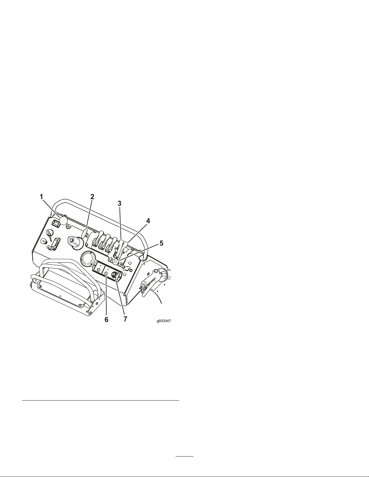
Figure10
1.Deector-gatecontrol
2.Spreader-patterncontrol6.ImpellerOn/Offswitch
3.Wide-distribution
impeller-gatelever
4.Narrow-distribution
impeller-gatelever
5.Narrow-spreader
distributionow-rate
knob
7.Impeller-speedcontrol
Usethedeector-gatecontroltotemporarilystop
thedischargeofgranularmaterialsfromtheleftside
ofthespreader.Closethedeectorgatewiththe
controlwhenitisnotdesirabletobroadcastgranular
materialsontosidewalks,parkinglots,orpatios.
Narrow-distributionImpeller-GateLever
Thenarrow-distributionimpeller-gateleveristhefth
leverlocatedatthetopcenterofthecontrolconsole
(Figure10).
•Tobroadcastanarrowpatternofgranularmaterial,
pullthenarrow-distributionimpeller-gatelever
rearwardfullytothelimitedOPENposition.
g033347
•Toclosetheimpellergate,pushthe
wide-distributionimpeller-gateleverforwardfully.
Note:Onlythewide-distributionimpeller-gate
leverclosestheimpellergate.Pushingthe
wide-distributionimpeller-gateleverforwardalso
resetsthenarrow-distributionimpeller-gatelever
totheforwardposition.
Narrow-SpreaderDistributionFlow-RateKnob
Thenarrow-spreaderdistributionow-rateknobis
locatedbelowthewide-andnarrow-impeller-gate
levers(Figure10).
Usethenarrow-spreaderdistribution-ow-rateknobto
controlthedischargerateofgranularmaterialfromthe
hopperontotheimpellerwhenthenarrow-distribution
impeller-gateleverisintheOPENposition(limited).
13
Page 14
•Rotatethenarrow-spreaderdistribution-ow-rate
knobclockwisetodecreasethedischargerateof
granularmaterialfromthehopper.
•Rotatethedistributionow-rate-knob
counterclockwisetoincreasethedischargerateof
granularmaterialfromthehopper.
ImpellerOn/OffSwitch
TheimpellerOn/Offswitchislocatedbelowthe
impeller-distributionow-rateknobatthebottomof
thecontrolconsole(Figure10).
UsetheimpellerOn/Offswitchtoruntheelectric
motorthatdrivestheimpeller.
•PresstheimpellerOn/Offswitchuptorunthe
impeller.
•PresstheimpellerOn/Offswitchdowntostopthe
impeller.
Impeller-speedControl
Theimpeller-speedcontrolislocatedtotherightof
theimpellerOn/Offswitchatthebottomofthecontrol
console(Figure10).
Theslotinthecam,aftersetting9onthecam,allows
theimpellergatetobeopenedtothemaximum
position.Thissettingcanbeusedfordrysand,ice
melt,orothermaterialsthataredifculttospread.
Note:Usecamsetting9maywhenyouarecleaning
outthehopper.
SprayerControls
Usetheimpeller-speedcontroltoadjusttherotational
speedoftheimpeller.
•Rotatetheimpeller-speedcontrolcounterclockwise
todecreasetherotationalspeedoftheimpeller.
•Rotatetheimpeller-speedcontrolclockwiseto
increasetheimpellerspeed.
Drop-rateCamandLinkage
Thedrop-ratecamandlinkagearelocatedatthefront
ofthemachineandbelowthehopperonthespreader
(Figure11).
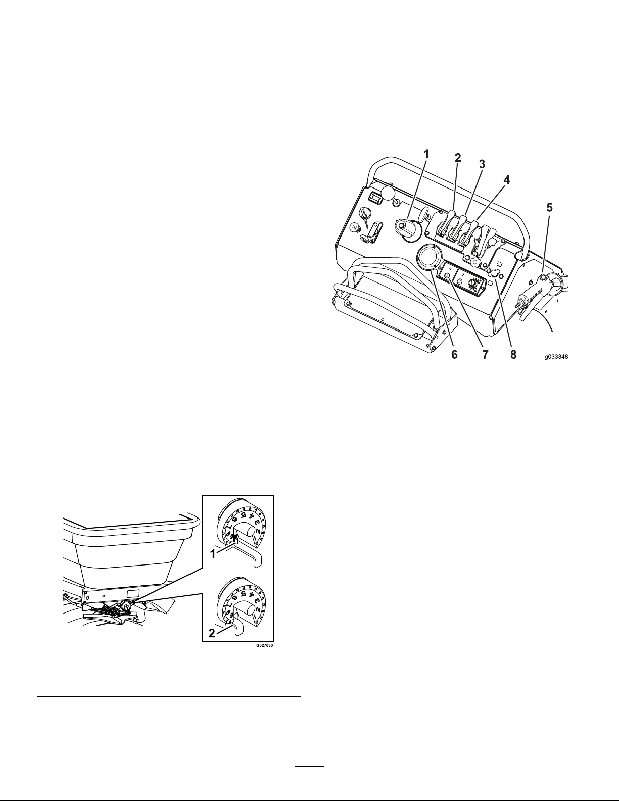
Figure12
1.Sprayer-pressurecontrol5.Sprayerwand
2.Tank-agitationlever
3.Narrow-spraypatternlever
4.Wide-spraypatternlever8.Wandpressurecontrol
SprayerPressureControl
6.Sprayer-pressuregauge
7.Sprayer-pumpswitch
Thesprayer-pressurecontrolislocatedonthecontrol
console(Figure12).
•Rotatethesprayer-pressurecontrolclockwiseto
increasethepressuretothesprayernozzles
•Rotatethepressure-controlcounterclockwiseto
thedecreasenozzlepressure.
TankAgitationLever
Thetank-agitationleverislocatedonthecontrol
console(Figure12).
g033348
Figure11
1.Slot–maximumposition
2.Linkage
Usethedrop-ratecamtosetthemaximumamountof
materialtobedispensedthroughtheimpellergate
andontotheimpeller.
g027033
Settingthetank-agitationlevertotheONposition
allowsthesprayerpumptocirculatethecontentinthe
spraytanktokeepthechemicalsolutionmixed.
•Pullthetank-agitationleverrearwardtocirculate
thecontentinthespraytank.
•Pushtheleverforwardtostopcirculatingthe
contentinthespraytank.
14
Page 15
Note:Donotuseagitationwhilespraying.Shut
offthetankagitationtoensureproperspray
distribution.
Note:Runtheenginespeedaboveidleandrunthe
sprayerpumpforthetankagitationtoworkeffectively.
Narrow-SprayPatternLever
Thenarrow-spraypatternleverislocatedonthe
controlconsole(Figure12).
•ToturnONthesprayerinanarrow-spraypattern
(thecenternozzleonly),pullthenarrow-spray
patternlevertowardyou.
•ToturnOFFthesprayer,pushthenarrow-spray
patternleverawayfromyou.
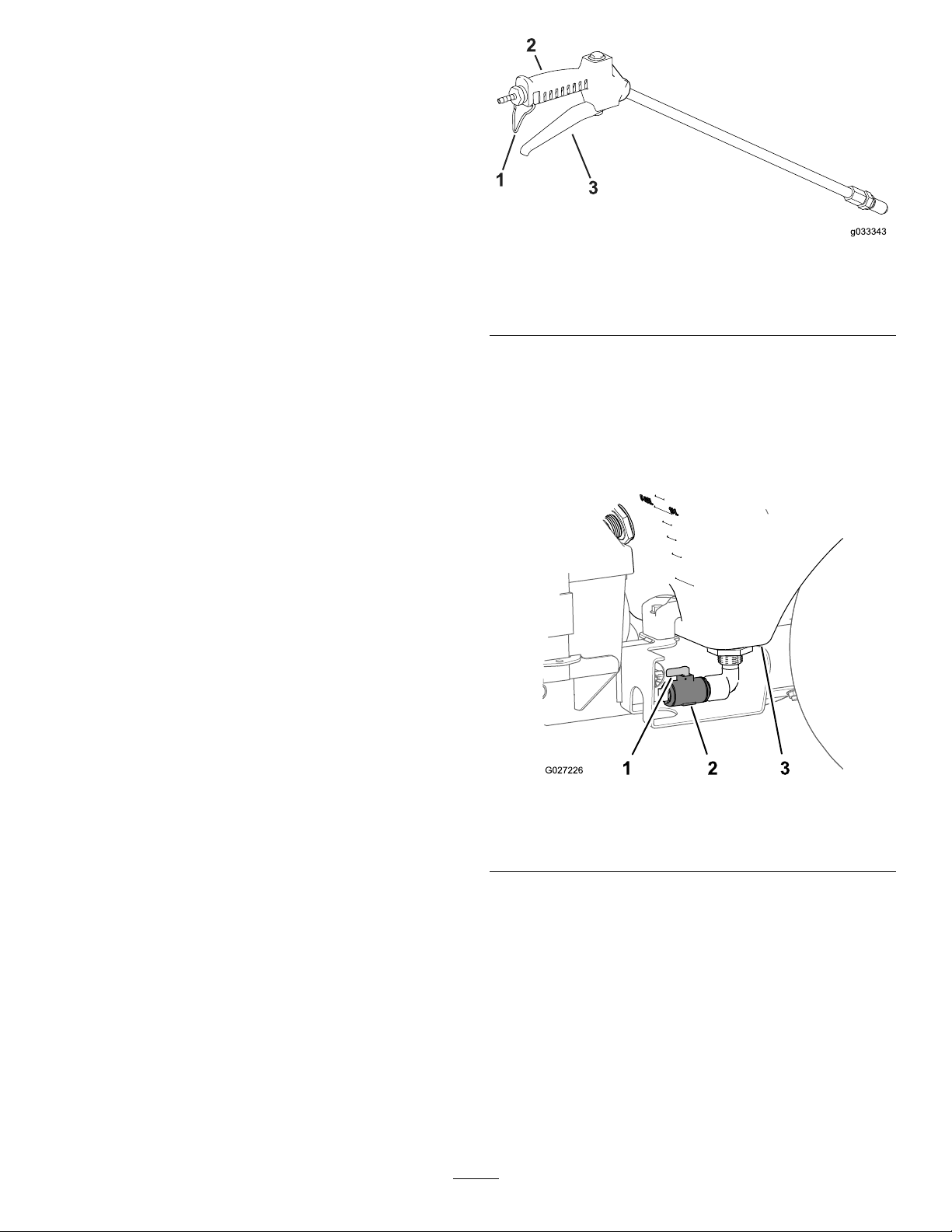
g033343
Figure13
1.Triggerlock3.Trigger
2.Spray-wandhandle
Wide-SprayPatternLever
Thewide-spraypatternleverislocatedonthecontrol
console(Figure12).
•ToturnONthesprayerinawide-spraypattern(the
rightandleftnozzles),pullthewide-spraypattern
levertowardyou.
•ToturnOFFthesprayer,pushthewide-spray
patternleverawayfromyou.
Sprayer-PressureGauge
Thesprayer-pressuregaugeislocatedonthecontrol
console(Figure12).
Usethepressuregaugetoseetheuidpressurein
thesprayersystem.
Sprayer-PumpSwitch
Thesprayer-pumpswitchislocatedonthecontrol
console(Figure12).
Usethesprayer-pumpswitchtostartandstopthe
pumpwhensprayingorcirculatingtheuidinthe
sprayertank(tank-agitation).
•Tostartthepump,pushdownonthetopofthe
sprayer-pumpswitch.
•Tostopthepump,pushdownonthebottomof
theswitch.
Spray-WandTriggerandTriggerLock
Thespray-wandtriggerandtriggerlockarelocated
onthebottomofthespray-wandhandle(Figure12
andFigure13).
•Tousethespraywand,holdthehandleofthe
wandsqueezethetrigger.
•TolockthetriggertotheONposition,fullysqueeze
thetriggeragainstthehandleandthenlatchthe
triggerlockoverthetrigger;tounlockthetrigger,
unlatchthetriggerlockfromthetrigger.
•Releasethetriggertostopthespray.
TankDrainValve
Thetankdrainvalveislocatedattheleftsideand
underthesprayertank(Figure15).
Usethetankdrainvalvetoemptythesprayertank
ofliquidchemicals.
g027226
Figure14
1.Handle(openposition)3.Sprayertank
2.Tankdrainvalve
•Toopenthevalve,rotatethehandleofthetank
drainvalve90°clockwise(leverin-linewithvalve).
•Toclosethevalve,rotatethehandle90°
counterclockwise.
Sprayer-Pump-SupplyValve
Thesprayer-pump-supplyvalveislocatedatthe
rightsideofthemachineandunderthesprayertank
(Figure15).
Usethesprayer-pump-supplyvalvetoshutoffthe
owofliquidchemicalstothepump.
15
Page 16
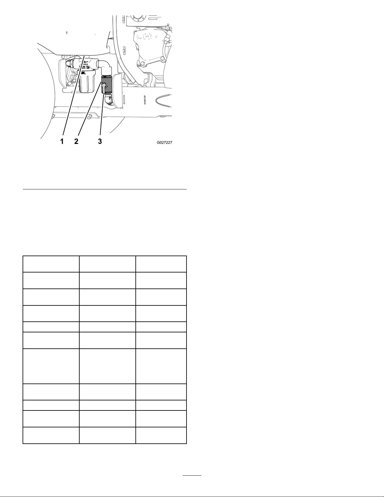
Figure15
1.Sprayertank3.Handle(openposition)
2.Sprayer-pump-supply
valve
•Toopenthevalve,rotatethehandlevalve90°
clockwise(leverin-linewithvalve).
•Toclosethevalve,rotatethehandle90°
counterclockwise.
Operation
Note:Determinetheleftandrightsidesofthe
machinefromthenormaloperatingposition.
BeforeOperation
BeforeOperationSafety
GeneralSafety
•Parkthemachineonalevelsurface;shutoffthe
engine;engagetheparkingbrake;removethe
g027227
key;waitforallmovementtostop;andallow
themachinetocoolbeforeadjusting,cleaning,
storing,orservicingit.
•Neverallowchildrenoruntrainedpeopletooperate
themachine.Localregulationsmayrestrictthe
ageoftheoperator.Theownerisresponsiblefor
trainingalloperatorsandmechanics.
•Becomefamiliarwiththesafeoperationofthe
equipment,operatorcontrols,andsafetysigns.
•Knowhowtostopthemachineandshutoffthe
enginequickly.
Specications
Overallwidth90cm(35.5
Overalllength171cm(67.5
Overallheight131cm(51.5
Weightsprayertankand
Maximum
machineweight
Hoppercapacity
Sprayertank
capacity
Maximumground
speed
hopperempty
onlyhopperfull307kg(676lb)
onlysprayertank
full
sprayertankand
hopperemptyand
1extrabagof
granularmaterial
inthetank
loadedmachine+
operator
forward9kph(5.5mph)
inches)
inches)
inches)
227kg(500lb)
309kg(682lb)
412kg(909lb)
≤513kg(1130lb)
79kg(175lb)
76L(20US
gallon)
•Checkthatoperator-presencecontrols,safety
switches,andshieldsareattachedandfunctioning
properly.Donotoperatethemachineunlessthey
arefunctioningproperly.
•Ifthemachinedoesnotfunctioncorrectlyoris
damagedinanyway,donotusethemachine.
Correcttheproblembeforeyouoperatethe
machineorattachment.
•Ensurethattheoperatorareaiscleanandfree
fromchemicalresidueanddebrisbuildup.
•Ensurethatalluidlineconnectorsaretightand
thatallhosesareingoodconditionbeforeapplying
pressuretothesystem.
ChemicalSafety
Chemicalsubstancesusedinthesprayersystem
maybehazardousandtoxictoyou,bystanders,and
animals,andtheymaydamageplants,soil,andother
property.
Ifyouwillusemorethan1chemical,readthe
informationoneachchemical.Refusetooperateor
workonthesprayerifthisinformationisnotavailable.
Beforeworkingonasprayersystem,ensurethatit
hasbeenneutralizedandtriplerinsedaccordingto
therecommendationsofthechemicalmanufacturer(s)
andthatallthevalveshavebeencycled3times.
16
Page 17

Verifythatthereisanadequatesupplyofcleanwater
andsoapnearby ,andimmediatelywashoffany
chemicalsthatcontactyou.
•Carefullyreadandfollowthechemicalwarning
labelsandmaterialsafetydatasheets(MSDS)for
allchemicalsused,andprotectyourselfaccording
tothechemicalmanufacturer'srecommendations.
•Alwaysprotectyourbodywhileusingchemicals.
Usetheappropriatepersonalprotectiveequipment
(PPE)toguardagainstcontactwithchemicals,
suchasthefollowing:
–safetyglasses,goggles,and/orfaceshield
–achemicalsuit
–arespiratororltermask
•Extinguishallcigarettes,cigars,pipes,andother
sourcesofignition.
•Useonlyanapprovedfuelcontainer.
•Donotremovethefuelcaporllthefueltank
whiletheengineisrunningorhot.
•Donotaddordrainthefuelinanenclosedspace.
•Donotstorethemachineorfuelcontainerwhere
thereisanopename,spark,orpilotlight,such
asonawaterheaterorotherappliance.
•Ifyouspillfuel,donotattempttostarttheengine;
avoidcreatinganysourceofignitionuntilthefuel
vaporshavedissipated.
–chemical-resistantgloves
–rubberbootsorothersubstantialfootwear
–acleanchangeofclothes,soap,and
disposabletowelsforcleanup
•Obtainpropertrainingbeforeusingorhandling
chemicals.
•Usethecorrectchemicalforthejob.
•Followthechemicalmanufacturer'sinstructionsfor
thesafelyapplyingthechemical.Donotexceed
therecommendedsystemapplicationpressure.
•Donotll,calibrate,orcleanthemachinewhile
people,especiallychildren,orpetsareinthearea.
•Handlechemicalsinawell-ventilatedarea.
•Havecleanwateravailable,especiallywhenlling
thespraytank.
•Donoteat,drink,orsmokewhileworkingnear
chemicals.
•Donotcleanspraynozzlesbyblowingthrough
themorplacingtheminyourmouth.
•Alwayswashyourhandsandotherexposedareas
assoonaspossibleafterworkingwithchemicals.
•Keepchemicalsintheiroriginalpackagesand
storedinasafelocation.
•Properlydisposeofunusedchemicalsand
chemicalcontainersasinstructedbythechemical
manufacturerandyourlocalcodes.
•Chemicalsandfumesaredangerous;neverenter
thetankorplaceyourheadoverorintheopening
ofatank.
•Followalllocal,state,andfederalregulationsfor
spreadingorsprayingchemicals.
PerformingDaily Maintenance
Beforestartingthemachineeachday ,performthe
followingdaily-checkprocedures:
•CheckingtheEngine-OilLevel(page52)
•CheckingtheSafetyInterlockSystem(page17)
•CheckingtheMachineforLooseHardware(page
67)
CheckingtheSafety InterlockSystem
ServiceInterval:Beforeeachuseordaily
CAUTION
Ifinterlockswitchisdisconnectedordamaged
themachinecouldoperateunexpectedly
causingpersonalinjury.
•Donottamperwiththeinterlockswitch.
•Checktheoperationoftheinterlockswitch
dailyandreplacedamagedswitchbefore
operatingthemachine.
Important:Ensurethatthesafetymechanisms
onyourmachineareconnectedandinproper
operatingconditionpriortooperatingyour
machine.
Thesafetyinterlocksystemisdesignedtopreventthe
enginefromstartingunlessyouengagetheparking
brake.
FuelSafety
•Useextremecareinhandlingfuel.Itisammable
anditsvaporsareexplosive.
17
Page 18
TestingtheStarterInterlock
ServiceInterval:Beforeeachuseordaily
1.Movethemachinetoalevelsurface.
2.Chockthewheelsofthemachine.
3.Disconnectthespark-plugwires.
4.Releasetheparkingbrake.
5.Withthemotion-controlleverintheNEUTRAL
positionturnthekeytotheSTARTposition.
Note:Thestartermustnotrotatetheengine.
•Ifthestarterrotatestheengineofyour
machine—themachinedoesnotpass
thistest,donotoperateit.Contactyour
authorizedT orodistributor.
•Ifthestarterdoesnotrotatetheengine—the
machinedoespassthetest:engagethe
parkingbrake,connectthespark-plugwire
tothesparkplug,andremovethechock(s)
fromthewheels.
Addthecorrectamountoffuelstabilizer/conditioner
tothegasoline.
Note:Afuelstabilizer/conditionerismosteffective
whenmixedwithfreshgasoline.T ominimizethe
chanceofvarnishdepositsinthefuelsystem,usefuel
stabilizeratalltimes.
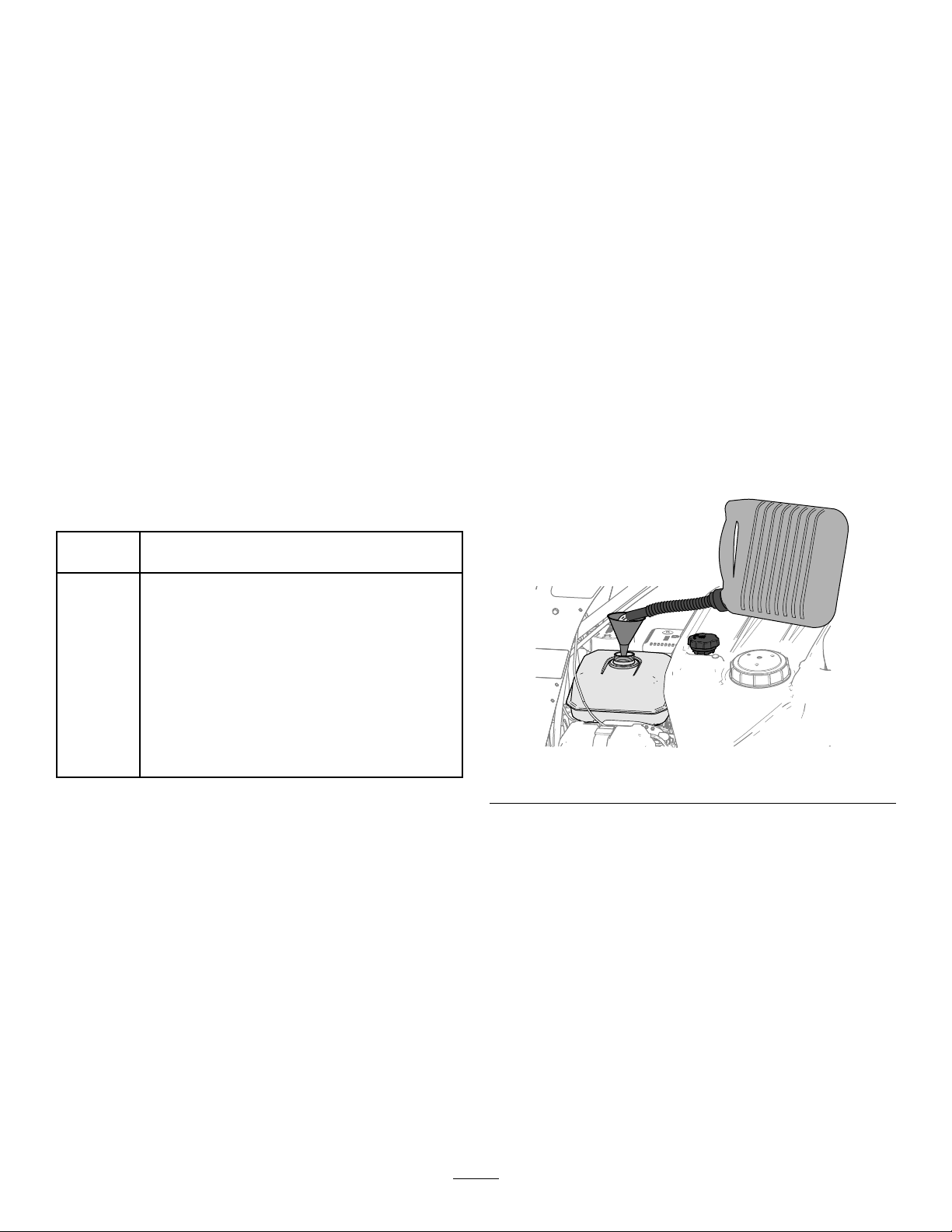
FillingtheFuelTank
Fueltankcapacity:6.1L(1.6USgallons)
Note:Refuelingtheengineisdifcultwhenusinga
largerrefuelingcontainersuchasacontainerwitha
19L(5USgal)capacity .
Tomakefuelingthemachineeasier,usea4to8L(1
to2USgal)fuelcontainerandafunnel.
1.Parkthemachineonalevelsurfaceandshut
offtheengine.
2.Allowtheenginetocool.
3.Cleanaroundthefuel-tankcapandremoveit
(Figure16).
FuelSpecication
Petroleum
fuel
Ethanol
blended
fuel
Important:Forbestresults,useonlyclean,fresh
fuel(lessthan30daysold).
•Donotusegasolinecontainingmethanol.
•Donotstorefueleitherinthefueltankorfuel
containersoverthewinterunlessyouuseafuel
stabilizer.
•Donotaddoiltogasoline.
Useunleadedgasolinewithanoctaneratingof87
orhigher((R+M)/2ratingmethod).
Useanunleaded-gasolineblendwithupto10%
ethanol(gasohol)or15%MTBE(methyltertiary
butylether)byvolumeisacceptable.Ethanoland
MTBEarenotthesame.
Gasolinewith15%ethanol(E15)byvolumeis
notapprovedforuse.Neverusegasolinethat
containsmorethan10%ethanolbyvolume,such
asE15(contains15%ethanol),E20(contains
20%ethanol),orE85(containsupto85%
ethanol).Usingunapprovedgasolinemaycause
performanceproblemsand/orenginedamage
whichmaynotbecoveredunderwarranty.
g249048
Figure16
4.Fillthetankwithfuel(Figure16)towithin6to13
mm(1/4to1/2inch)fromthetopofthetank.Do
notllintothellerneckofthetank.
Important:Donotllthetankmorethan
6mm(1/4inch)fromthetopofthetank
becausethefuelneedsroomtoexpand.
5.Installthefuel-tankcapsecurely.
Using Stabilizer/Conditioner
Useafuelstabilizer/conditionerinthemachineto
providethefollowingbenets:
Important:Donotusefueladditivescontaining
methanolorethanol.
6.Wipeupanyspilledfuel.
18
Page 19

DuringOperation
DuringOperationSafety
•Lookbehindanddownbeforebackinguptobe
sureofaclearpath.
•Usecarewhenapproachingblindcorners,shrubs,
trees,orotherobjectsthatmayobscureyour
vision.
GeneralSafety
•Theowner/operatorcanpreventandisresponsible
foraccidentsthatmaycausepersonalinjuryor
propertydamage.
•Wearappropriateclothing,includingeye
protection;longpants;substantial,slip-resistant
footwear;andhearingprotection.Tiebacklong
hair,securelooseclothing,anddonotwearloose
jewelry.
•Wearappropriatepersonalprotectiveequipment
asdirectedinChemicalSafety(page16).
•Useyourfullattentionwhileoperatingthe
machine.Donotengageinanyactivitythat
causesdistractions;otherwise,injuryorproperty
damagemayoccur.
•Donotoperatethemachinewhileill,tired,or
undertheinuenceofalcoholordrugs.
•Nevercarrypassengersonthemachineandkeep
bystandersandpetsawayfromthemachine
duringoperation.
•Donottrytostabilizethemachinebyputting
yourfootontheground.Ifyoulosecontrolofthe
machine,stepofftheplatformandawayfromthe
machine.
•Donotplaceyourfeetundertheplatform.
•Donotmovethemachineunlessyouarestanding
withbothfeetontheplatformandyourhandsare
holdingontothereferencebars.
•Operatethemachineonlyingoodvisibilitytoavoid
holesorhiddenhazards.
•Beforeyoustarttheengine,ensurethatyouare
intheoperatingposition,thetransmissionisin
neutral,andtheparkingbrakeisengaged.
•Beforeyoustarttheengine,ensurethatyouare
intheoperatingposition,thetransmissionisin
neutral,andtheparkingbrakeisengaged.
•Usecarewhenapproachingblindcorners,shrubs,
trees,orotherobjectsthatmayobscureyour
vision.
•Ensurethatyouhavegoodfootingwhileusingthis
machine,especiallywhenbackingup.
•Keepclearofanydischargeareaofthesprayer
nozzlesandspraydrift.Keepbystandersandpets
asafedistanceawayfromthemachine.
•Donotoperatethemachineneardrop-offs,
ditches,orembankments.Themachinecould
suddenlyrolloverifawheelgoesovertheedge
oriftheedgegivesway.
•Reducethespeedandloadwhenoperatingon
roughterrain,unevenground,andnearcurbs,
holes,andothersuddenchangesinterrain.
Loadsmayshift,causingthemachinetobecome
unstable.
•Stopthemachine,shutofftheengine,remove
thekey,engagetheparkingbrake,andinspect
fordamageafterstrikinganobjectorifthereis
anabnormalvibrationinthemachine.Makeall
necessaryrepairsbeforeresumingoperation.
•Slowdownandusecautionwhenmakingturns
andcrossingroadsandsidewalkswiththe
machine.Alwaysyieldtheright-of-way.
•Useextracautionwhenoperatingthemachineon
wetsurfaces,inadverseweatherconditions,at
higherspeeds,orwithafullload.Stoppingtime
anddistanceincreaseintheseconditions.
•Neverrunanengineinanenclosedareawhere
exhaustgassescancollect.
•Neverleavearunningmachineunattended.
•Donottouchtheengineormuferwhiletheengine
isrunningorsoonafterithasshutoff.These
areasmaybehotenoughtocauseburns.
•Beforeleavingtheoperatingposition,dothe
following:
–Stopthemachineonlevelground.
–Shutthewide-distributionimpeller-gateforthe
spreaderandshutoffthesprayer-pumpswitch.
–Shutofftheengineandremovethekey.
–Engagetheparkingbrake.
–Waitforallmovingpartstostop.
•Donotoperatethemachinewhenthereistherisk
oflightning.
•Donotusethemachineasatowingvehicle.
•Donotchangethegovernorspeedoroverspeed
theengine.
•Useaccessoriesandattachmentsapprovedby
Toroonly .
•Neversprayorspreadchemicalswhilepeople,
especiallychildren,orpetsarenearby .
19
Page 20

SprayerandSpreaderOperation Safety
•Thespraywandtrapsliquidsunderhighpressure,
evenwhenengineisoff.High-pressurespray
couldcauseseriousinjuryordeath.
–Keepclearofnozzleanddonotdirectspray
orstreamatpeople,pets,ornon-workarea
property.
–Donotdirectsprayonornearelectrical-power
componentsorsource.
–Donotattachhosesorothercomponentsto
theendofthespray-wandnozzle.
–Donotattempttodisconnectthespray
wandfromthemachinewhilethesystemis
pressurized.
–Donotusespraywandiftriggerlockis
damagedormissing.
–Rotatethespray-wandlocktotheOFFposition
whenjobiscomplete.
•Donottouchtheimpellerforthespreaderwhile
theimpellerisrotating.
•Stopspreading/sprayingwhenmakingtightturns
tominimizechemicaldrift.
•Chemicalsmaydriftandcauseinjurytopeople
andanimals;itmayalsodamageplants,soil,or
otherproperty.
•Liquidloadsandgranularmaterialscanshift.This
shiftinghappensmostoftenwhileturning,going
upordownhills,suddenlychangingspeeds,or
whiledrivingoverroughsurfaces.Shiftingloads
cancausethemachinetotipover.
•Safelyrelievepressurefromspraywandevery
timetheengineisshutoff.
•Whendrainingorrelievingsystem,donotlet
anyonestandinfrontofnozzlesanddonotdrain
onaperson’sfeet.
usecommonsenseandgoodjudgmentwhen
performingthissurvey.
•Avoidstarting,stopping,orturningthemachine
onslopes.Travelupanddownonslopes.Avoid
makingsuddenchangesinspeedordirection.
Ifyoumustturnthemachine,turnitslowlyand
graduallydownhill,ifpossible.Usecarewhen
reversingthemachine.
•Donotoperateamachinewhenyouareuncertain
aboutthetraction,steering,orstability .
•Removeormarkobstructionssuchasditches,
holes,ruts,bumps,rocks,orotherhiddenhazards.
Tallgrasscanhideobstructions.Uneventerrain
couldoverturnthemachine.
•Beawarethatoperatingthemachineonwet
surfaces,acrossslopes,ordownhillmaycause
themachinetolosetraction.Lossoftractiontothe
wheelsmayresultinslidingandalossofbraking
andsteering.
•Useextremecautionwhenoperatingthemachine
neardrop-offs,ditches,embankments,water
hazards,orotherhazards.Themachinecould
suddenlyrolloverifawheelgoesovertheedge
ortheedgecavesin.Establishasafetyarea
betweenthemachineandanyhazard.
•Useextracarewhileoperatingthemachinewith
attachments;theycanaffectthestabilityofthe
machine.
•Iftheenginestallsoryoubegintolosemomentum
whileclimbingahill,graduallyapplythebrakes
andslowlybackstraightdownthehill.
•Alwayskeepthetransmissioningear(ifapplicable)
whenyoudrivethemachinedownaslope.
•Donotparkthemachineonanincline.
•Theweightofthematerialinthetankcanchange
thehandlingofthemachine.Toavoidlossof
controlandpersonalinjury,followtheseguidelines:
SlopeSafety
Slopesareamajorfactorrelatedtolossofcontroland
rolloveraccidents,whichcanresultinsevereinjuryor
death.Y ouareresponsibleforsafeslopeoperation.
Operatingthemachineonanysloperequiresextra
caution.
•Reviewtheslopeinstructionslistedbelowfor
operatingthemachineonslopesandtodetermine
whetheryoucanoperatethemachineinthe
conditionsonthatdayandatthatjobsite.
Changesintheterraincanresultinachangein
slopeoperationforthemachine.
•Determineiftheslopeissafeformachine
operation,includingsurveyingthesite.Always
–Whenoperatingwithaheavyload,reduceyour
speedandallowforsufcientbrakingdistance.
Donotsuddenlyapplythebrakes.Useextra
cautiononslopes.
–Liquidloadsshift,especiallywhileturning,
goingupordownslopes,suddenlychanging
speeds,orwhiledrivingoverroughsurfaces.
Shiftingloadscancausethemachinetotip
over.
20
Page 21
OperatingtheMachine
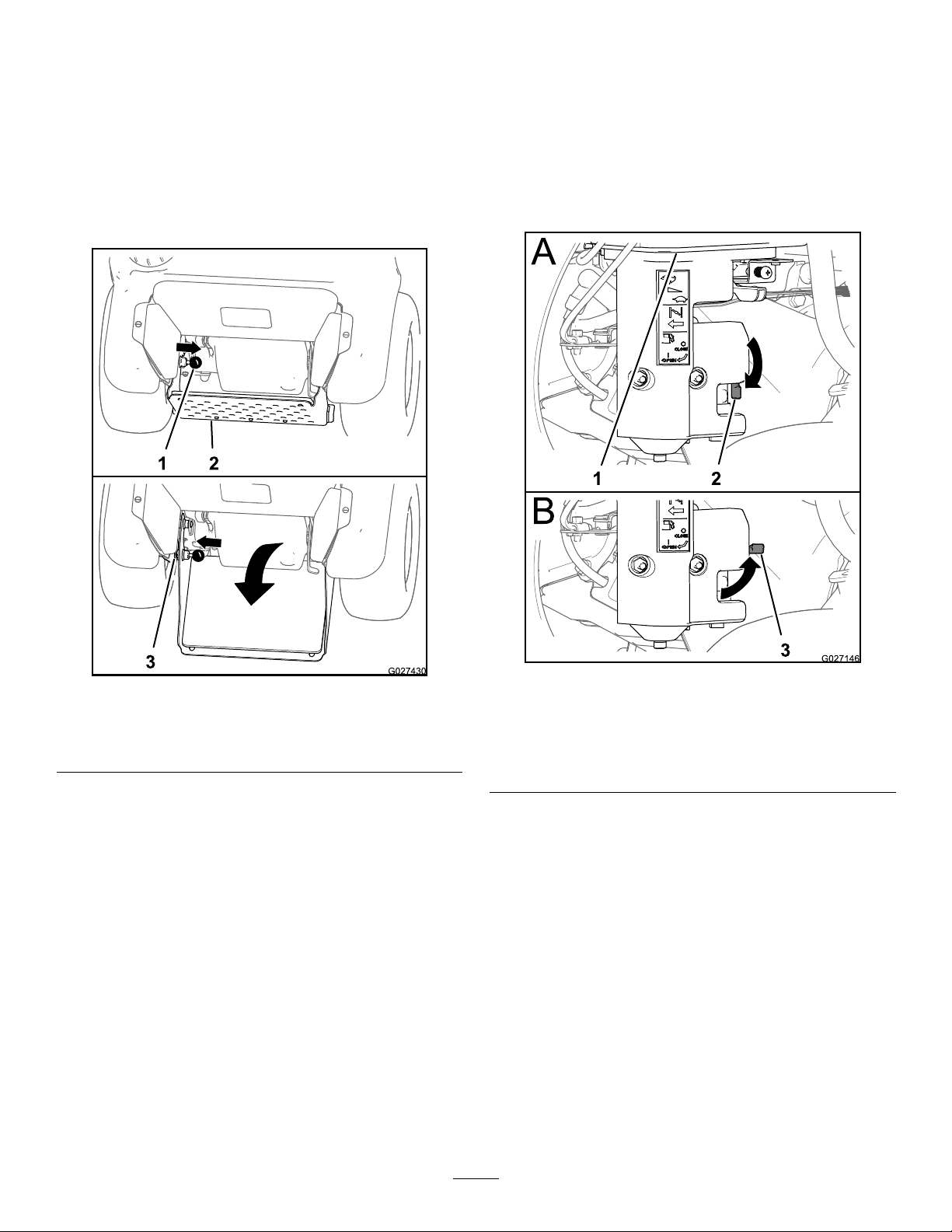
OpeningandClosingthe Fuel-Shut-OffValve
ExtendingandRetractingthe Operator’sPlatform
ExtendingtheOperator’sPlatform
1.Pulltheplatform-lockknobinwarduntilthepinof
clearstheupperholeinthechassis(Figure17).
Controlfuelowtotheenginewiththefuel-shut-off
valveasfollows:
•Rotatethehandleforthefuel-shut-offvalve90
degreesclockwisetotheopenthevalve.
•Rotatefuel-shut-offvalvehandle90degrees
counterclockwisetoclosethevalve.
Figure17
1.Platform-lockknob
2.Operator’splatform
2.Rotatetheoperator’splatformdownuntilthepin
oftheplatformlockalignswiththelowerholein
thechassis(Figure17).
3.Movetheplatform-lockknoboutwarduntilthe
pinprotrudesthroughthelowerhole(Figure17).
3.Lowerchassishole
RetractingtheOperator’sPlatform
1.Pulltheplatform-lockknobinwarduntilthepin
clearstheupperholeinthechassis(Figure17).
2.Rotatetheoperator’splatformupuntilthepinof
theplatformlockalignswiththeupperholein
thechassis(Figure17).
3.Movetheplatform-lockknoboutwarduntilthe
pinprotrudesthroughtheupperhole(Figure17).
g027430
1.Fueltank
2.Fuel-shutoffvalve(open
position)
Figure18
3.Fuel-shutoffvalve(closed
position)
g027146
StartingtheEngine
1.Ensurethatthefuel-shutoffvalveisopen;refer
toOpeningandClosingtheFuel-Shut-OffV alve
(page21).
2.Movethesteering-control/motion-control
leverinNEUTRALpositionandengagethe
parkingbrake;refertoSteeringControl(page
11),Motion-ControlLever(page11),and
Parking-BrakeLever(page12).
Note:T ostarttheengine,youmustengagethe
parkingbrake.(Y oucanstarttheenginewhile
youareofftheplatform.)
3.Movethethrottlelevermidwaybetweenthe
SLOWandFASTpositions;refertoThrottle
Control(page12).
21
Page 22
4.Iftheengineiscold,pullupthechokecontrolto
theONposition;refertoChokeControl(page
12).
Important:Ifthemotion-controlleverdoesnot
returntotheNEUTRALpositionwhenyourelease
it,contactanAuthorizedServiceDealer.
Note:Iftheengineiswarm,pushdownthe
chokelevertotheOFFposition.
5.RotatetheignitionswitchtotheSTARTposition;
refertoIgnitionSwitch(page12).
Note:Whentheenginestarts,releasethe
switch.
Important:Donotcranktheengine
continuouslyformorethan10secondsata
time.Iftheenginedoesnotstart,allowa60
secondcool-downperiodbetweenstarting
attempts.Failuretofollowtheseguidelines
canoverheatthestartermotor
6.IfthechokecontrolisintheONposition,
graduallymovetheleverdown,towardtheOFF
positionastheenginewarmsup.
ShuttingOfftheEngine
1.Movethesteering-control/motion-controllever
totheNEUTRALpositionandbringthemachine
toafullstop;refertoSteeringControl(page1 1)
andMotion-ControlLever(page11).
2.Placethethrottleinthemidwaybetweenthe
SLOWandFASTpositions;refertoThrottle
Control(page12).
3.Runtheengineforaminimumof15seconds,
thenturntheignitionswitchtotheOFFposition;
refertoIgnitionSwitch(page12).
4.Engagetheparkingbrake;refertoParking-Brake
Lever(page12).
5.Removethekey;refertoIgnitionSwitch(page
12).
6.Closethefuel-shutoffvalvewhenyouare
notusingthemachineforafewdays,when
transportingit,orwhenitisparkedinsidea
building;refertoOpeningandClosingthe
Fuel-Shut-OffValve(page21).
Important:Tobeginmovingthemachine
(forwardorbackward),theparking-brakelever
mustbereleased(pulledup)beforeyoumovethe
motion-controllever.
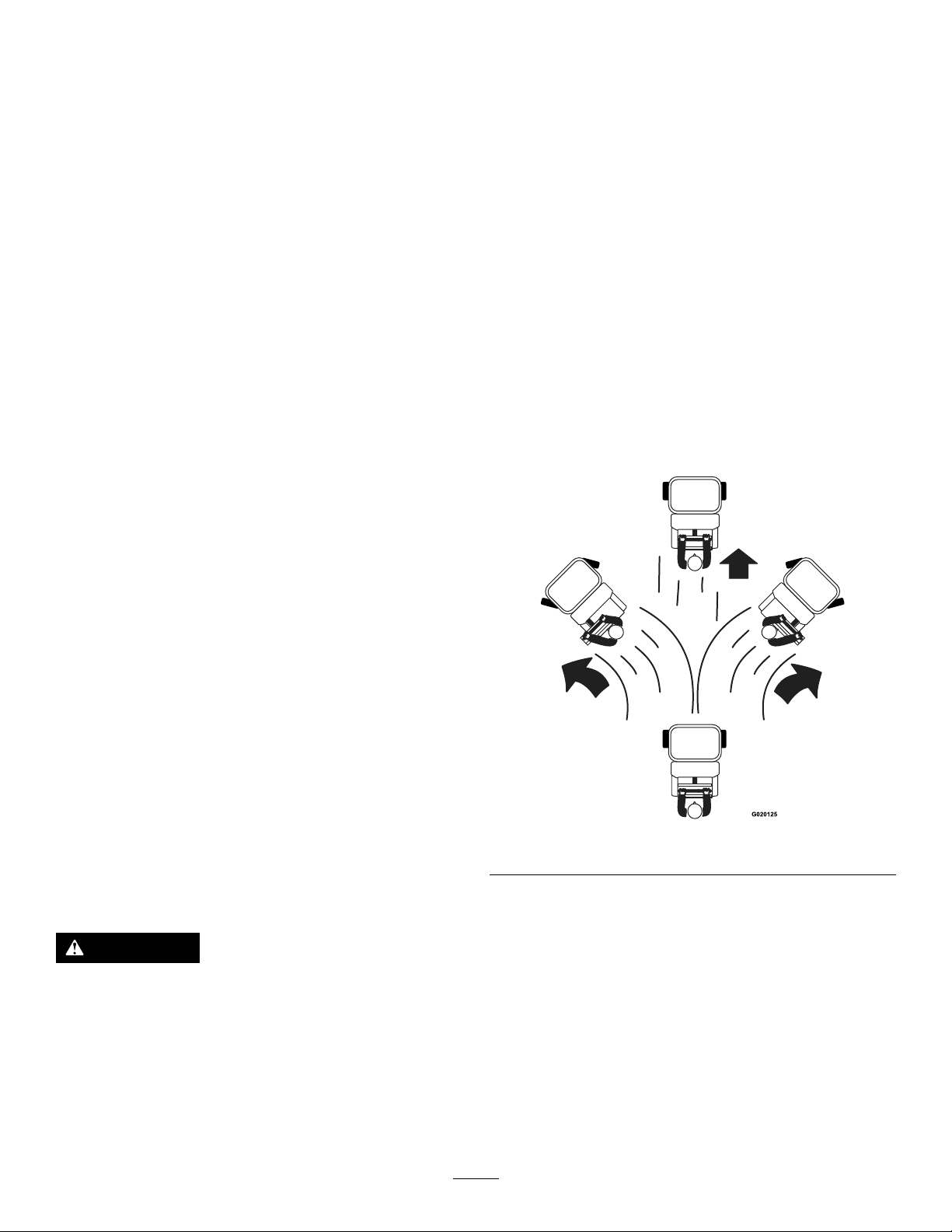
DrivingtheMachineForward
1.Movethemotion-controllevertotheNEUTRAL
position.
2.Releasetheparkingbrake.
3.Todrivethemachine,performthefollowing:
•Tomovethemachineforwardinastraight
line,centerthesteeringcontrolandmove
themotion-controlleverforward.
Note:Themachinemovesfasterthefarther
youmovethemotion-controlleverawayfrom
theNEUTRALposition.
g020125
Figure19
DrivingtheMachine
CAUTION
Machinecanturnrapidlybymovingthe
steeringcontroltothefarrightorleft.
Operatormaylosecontrolofthemachine,
whichmaycausedamagetothemachineor
injury.
•Usecautionwhenmakingturns.
•Slowdownthemachinebeforemaking
sharpturns.
•Toturnleftorright,movethesteeringcontrol
towardthedesiredturndirection.
•Tostopthemachine,movethemotion-control
leverintheNEUTRALposition.
Note:Stoppingdistancemayvary
dependingonthespreader-sprayerload.
Note:Whenyoureleasethemotion-control
lever,itautomaticallyreturnstotheNEUTRAL
position.
22
Page 23
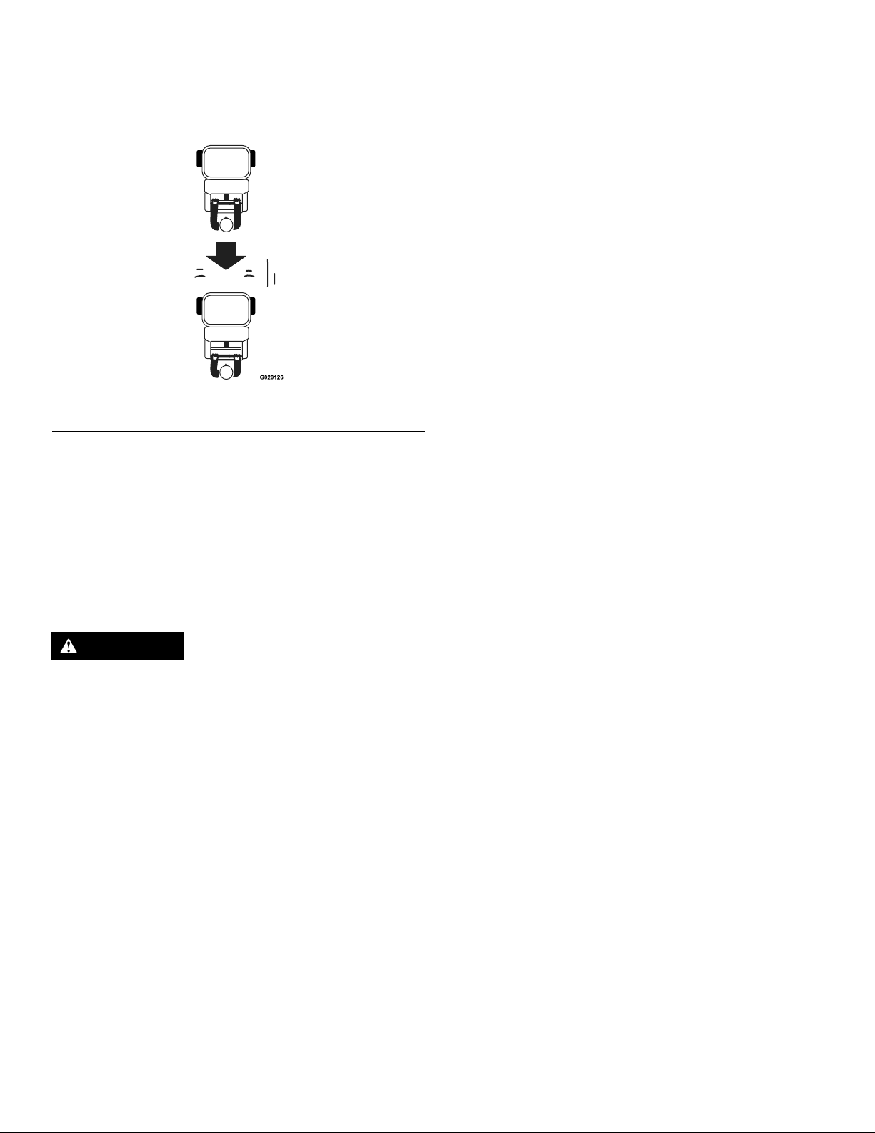
DrivingtheMachineinReverse
1.Movethemotion-controllevertotheNEUTRAL
position.
2.Tomovethemachinerearwardinastraightline,
slowlymovethemotion-controlleverrearward.
Figure20
BeforeOperatingtheSpreader
Beforeyoustartusingthespreader,calibratethe
spreaderforthematerialthatyouwilldisperse;refer
toCalibratingtheSpreader(page23).
Important:Priortollingthehopper,verifythat
youhavesettheproperspreader-applicationrate.
CalibratingtheSpreader
Calibratethespreadereachtimeyouuseanew
material.Thespreaderbroadcastsmaterialina
pattern1.5to6.7m(5to22ft)widedependingonthe
materialparticlesize,volume/density ,rateoftravel,
andwindconditions.
UsetheSpreadingCharts(page29)alongwith
informationfromDeterminingtheDistributionPattern
(page24),DeterminingtheEffectiveSpreadingWidth
g020126
(page25),andCalculatingtheApplicationRate(page
25)whencalibratingthespreader.
Toturnleftorright,movethesteeringcontrol
towardthedesiredturndirection.
3.Tostopthemachine,movethemotion-control
levertotheNEUTRALposition.
Note:Stoppingdistancemayvarydepending
onthespreader-sprayerload.
OperatingtheSpreader
CAUTION
Chemicalsarehazardousandcancause
personalinjury.
•Readthechemicalmanufacture’s
directionsonthelabelbeforehandling
thechemicals;followallmanufacturer
recommendationsandprecautions.
•Keepchemicalsawayfromyourskin.
Shouldcontactoccur,washtheaffected
areathoroughlywithsoapandcleanwater.
PreparingtheTestSiteandMachine
Operatorsuppliedequipment:15shallowcollection
pansand15graduatedmeasuringcylinders
Note:Themostaccuratemethodtomeasure
thedistributionusesshallowcollectionpansand
graduatedmeasuringcylinders.Intheexamplebelow,
the15shallowcollectionpansapproximately30cm
(12inches)wide,91cm(36inches)long,and5cm
(2inches)tall.
1.Placeonepaninthecenterofthedrivepath.
Arrangethenexttwopans,oneoneachside,
farenoughaparttoallowadequateroomforthe
drivetiresofthemachinetopassaroundthe
centerpan.
2.Placetheremainingpansinastraightlineas
showninFigure21orFigure22.
•Forlargergranulematerials:
Space6additionalpans,oneachside,12
inches(30cm)apart(Figure21).
•Weareyeprotection,gloves,andanyother
protectiveequipmentrecommendedbythe
chemicalmanufacturer.
Usethespreadertodispersesfree-owinggranular
substancessuchasgrassseed,fertilizer,icemelt,
etc.Whenyouusethespreader,rstllthegranular
hopper,thenapplythegranularmaterialstothework
site,andnallycleanthehopper.
Important:Whenyouuseyourspreader,
thoroughlycleanitattheendoftheday.
23
Page 24
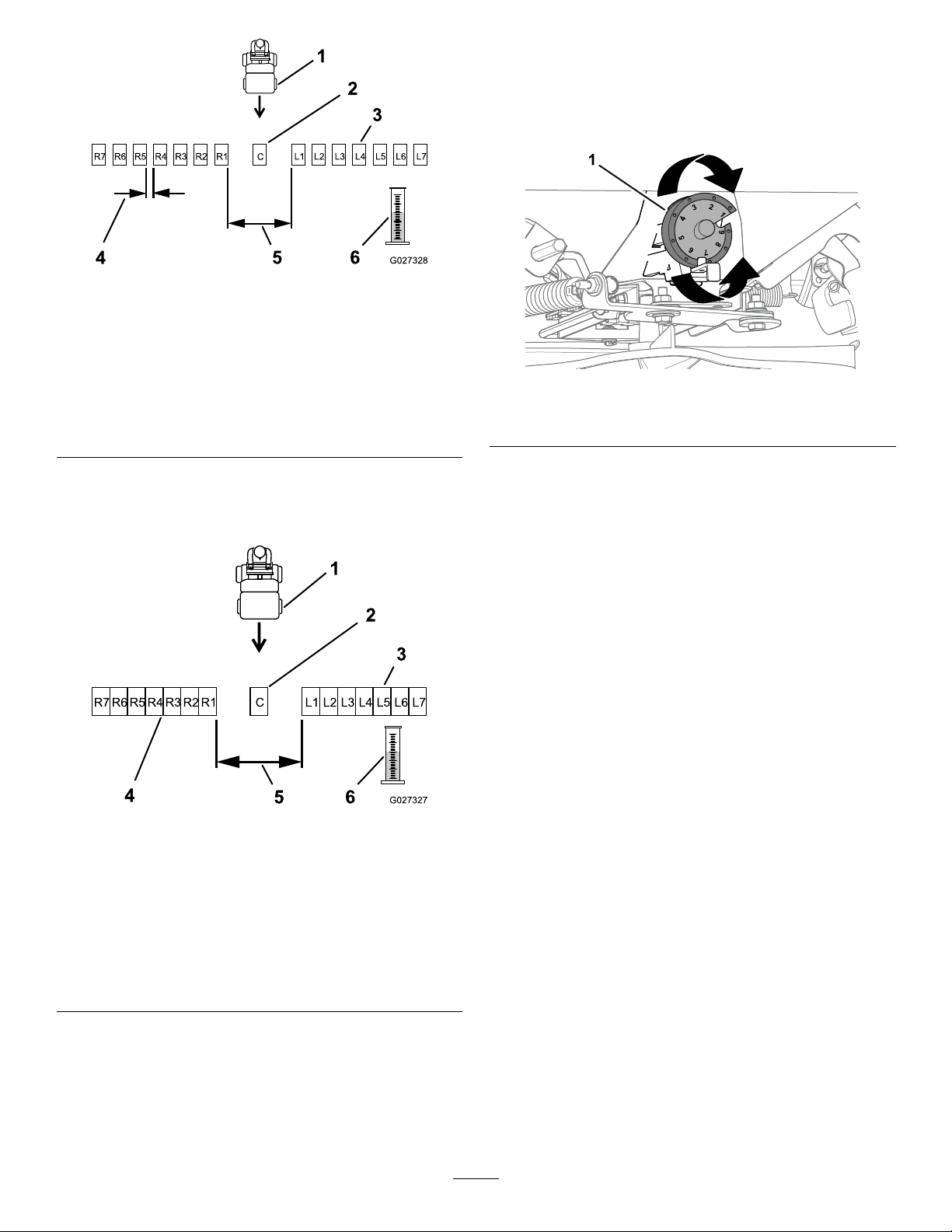
Figure21
Panspacingforlargergranulematerials
4.Determinetheapplicationrateandtherelated
drop-ratecamsetting;refertoSpreadingCharts
(page29).
5.Rotatethedropratecam(Figure23)tothecam
settingyoudeterminedinstep4.
g027328
1.Spreadermovingtoward
pans
2.Centerpan5.30cm(12inch)gap
3.Collectionpans(gap
betweeneach)
4.L1andR1collectionpan
gap(spreadaparttoallow
machinetopassthrough)
6.Graduatedmeasuring
cylinder
•Forsmallgranulematerials:
Place6additionalpans,oneachside,with
nogapinbetweeneachpan(Figure22).
Figure22
Panspacingforsmallgranulematerials
1.Spreadermovingtoward
pans
2.Centercollectionpan
3.Lestcollectionpans(no
gapbetweeneach)
3.Movethemachinefarenoughawayfromthe
testarea(wherethecollectionpansarelocated)
toensurethatthemachinetravelsatthedesired
spreadingspeedbeforereachingthesite.
4.Rightcollectionpans(no
gapbetweeneach)
5.L1andR1collectionpan
gap(spreadaparttoallow
machinetopassthrough)
6.Graduatedmeasuring
cylinder
g259776
Figure23
1.Dropratecam
6.Fillthehopperapproximatelyhalf-fullwiththe
desiredmaterial;refertoFillingtheSpreader
Hopper(page26).
DeterminingtheDistributionPattern
1.Setthespreaderpatterncontroltothemiddleof
itstravel;referto.
2.Settheimpellerspeedtotheappropriate
broadcastingrate.
3.Drivethemachinetowardthetestsiteatthe
appropriatespeed.
4.Asyouapproachthecenterpan,pullthewide
distributiongranulargatecontroltotheopen
position,anddriveoverthecenterpan.
5.Closethegatecontrol,movemotion-control
g027327
levertotheNEUTRALposition,shutoffthe
engine,waitforallmovingpartstostop,remove
key,andengageparkingbrake.
6.Labeleachgraduatedmeasuringcylinderto
correspondwiththedistributionpans(suchas
L2,L1,Center,R1,R2);refertoFigure21and
Figure22.
7.Oneatatime,takeacollectionpananddump
thecontentsintothecorrespondinggraduated
cylinder.Recordtheamountofmaterial
collectedandreturnthepantoitslocation.
Repeatthisuntilallpancontentshavebeen
emptied.
Note:Repeatbroadcastingoverthetestsite
severaltimes,movinginthesamedirection
eachtime,untilenoughmaterialisdispensedto
thecollectionpantohalfllagraduatedcylinder.
24
Page 25

8.Withthegraduatedmeasuringcylinderinthe
samestraightlineasthepans,evaluatethe
volumeofmaterialineachcylindertodetermine
thequalityofthedistributionfromthespreader.
9.Toadjustthespreaderpattern,refertothe
AdjustingtheSpreaderPattern(page30).
10.Fillthehopperhalf-fullofthedesiredmaterial
andrepeatsteps1through9untilyouachieve
auniformpattern.
DeterminingtheEffectiveSpreadingWidth
Usetheeffectivewidthtodeterminetheuniform
distributionofthematerial.
Note:Thespreadingwidthrangeis6to8m(20to
25ft).
1.Afterthespreaderpatterniscorrectlyadjusted,
evaluatetheamountofmaterialinthecenter
graduatedmeasuringcylinder.
2.Locatethe2graduatedcylinder,oneeachside
ofcenter,thatcontain1/2themeasuredamount
ofthematerialthatyouobservedinthecenter
graduatedcylinder.
3.Gotothetwocorrespondingpans.Startingfrom
theouteredge,measurethedistancebetween
leftpan,acrossthecenterpan,totheouteredge
oftherightpan,andrecordthemeasurement.
Recordtheeffectivespreadingwidth
here:
.
CalculatingtheApplicationRate
1.Determinetheareaandamountofmaterialthat
youareapplyingtothejobsiteandrecordthose
amountsintheareaandmaterialsworksheet.
Recordthejobsitearea
here:
.
Recordtheamountofjobsitematerial
here:.
2.Initially,usetherecommendedapplicationrate
indicatedintheSpreadingCharts(page29)
sectionorusetheraterecommendedlistedon
theproductmanufacturer’slabelasaguideto
helpdeterminetheamountofmaterialthatyou
wouldspreadovera93m
2
(1,000ft2)area.
Note:Inthisexamplethecalibrationcourseis
1.8m(6ft)by51m(167ft).
3.Settheappropriatedrop-ratecamsetting;refer
totheSpreadingCharts(page29)asastarting
point.
4.Addmaterialtothehopper.
Note:Inthisexampleweadded11.3kg(25
lb)ofmaterial.
5.Drivethespreaderoverthecalibrationcourse
whileapplyingthematerial.
6.Emptytheremainingmaterialofthehopperinto
acleanbucket;refertoEmptyingtheSpreader
(page26).
PreparingtheCalibrationCoursefor
CalculatingtheApplicationRate
1.Determineacourselengthbydividing93m
(1,000ft2)bytheeffectivespreadwidththat
youdeterminedinDeterminingtheEffective
SpreadingWidth(page25);usethecourse
lengthformula.Recordthecourselength
here:
.
CalibrationCourseLengthFormula
93m2(1,000ft2)
Formula
Example
/Effectivewidth
measurement
93m2(1,000ft2)
/1.8m(6ft)
=
=
Calibrationcourse
51m(167ft)
Note:Inthisexampletheeffectivewidth
measures1.8m(6ft).
2.Measureandvisiblymarkthecourselength.
Ensurethatyouallowenoughdistancebefore
thestartingmarkersothatthespreadermoving
forwardatfullspeedwhencrossingtherst
markofthecourse.
7.Weighthebucketcontainingthematerialand
recordtheweight.Pourthecontentsback
intothehopperandthenweightheempty
2
bucket.Calculatetheremainingmaterialweight
usingtheremainingmaterialweightformula.
Recordtheremainingmaterialweight
here:
.
RemainingMaterialWeightFormula
(Remaining
materialand
Formula
length
Example
bucketweight)-
(Bucketweight)
10kg(22lb)—
1kg(2lb)
Remainingmaterial
=
=
weight
9kg(20lb)
Note:Inthisexample,9kg(20lb)ofmaterial
remaininthehopperafterapplyingthematerial
tothetestcourse.
8.Calculateappliesmaterialweighusing
theappliedmaterialformulathatfollows.
Recordtheappliedmaterialweight
here:
.
25
Page 26

AppliedMaterialWeightFormula
(Original
materialweight)
Formula
Example
-(Remaining
materialweight)
11.3kg(25lb)
—9kg(20lb)
3
=
=
Note:Thiscalculationmeansthat2.3kg(5lb)
ofmaterialwasappliedtothe93m
testcourse.
9.Ifnecessary,adjustthedrop-ratecamtoachieve
therecommendedapplicationrate.Onceyou
achievethecorrectapplicationrate,repeat
thisprocedureanadditionaltimetoverifyyour
results.
Important:Designateanewcalibration
courseeachtime,sothattheturfisnot
damagedbyexcessiveapplicationof
material.
FillingtheSpreaderHopper
Appliedmaterial
2.3kg(5lb)
weight
2
(1,000ft2)
g027326
Figure24
1.Cover
2.Hopper
3.Drop-ratecam
Maximumhopperweightcapacity:79kg(175lb)
1.Drivethemachinetotheworksite.
2.Movethemachinetoalevelsurface,move
motion-controllevertotheNEUTRALposition,
shutofftheengine,waitforallmovingpartsto
stop,removekey,andengageparkingbrake.
3.Ensurethatthewide-distributionimpeller-gate
leverisinthefullyforward(closed)position;
refertoWide-distributionImpeller-GateLever
(page13).
4.UsetheSpreadingCharts(page29)to
determinethesettingforthedrop-ratecam
(Figure24).
Note:Ifthesettingisnotlistedforthetypeof
materialthatyouareusing,setthecamtothe
settingwithalowervaluethenadjustasneeded.
5.Removethecoverfromthehopper,addthe
materialthatyouarespreading,andinstallthe
coverontothehopper(Figure24).
Note:Donotoverloadthehopper;the
maximumweightcapacityofthehopperis79
kg(175lb).
Note:Youmayplace1extrabagofgranular
productontopofthesprayertankifnecessary .
EmptyingtheSpreader
RemovingtheImpeller
1.Movethemachinetoalevelsurface,move
motion-controllevertotheNEUTRALposition,
shutofftheengine,waitforallmovingpartsto
stop,removekey,andengageparkingbrake.
2.Emptythehopperbyscoopingoutasmuchof
thematerialaspossible.
3.Removethe4thumbscrewsthatsecurethefront
cover(belowtheimpeller)tothechassis,and
removethecover(Figure25).
26
Page 27

Figure25
1.Forwardcover3.Thumbscrew
2.Clipnut
g033530
4.Removethedrivepinthatsecuretheimpellerto
theshaftoftheimpellermotor,andremovethe
impellerfromtheshaft(Figure26andFigure
27).
Figure26
g027325
Figure27
5.Placeashallowpanundertheshaftofthe
impellermotor(Figure27).
DisconnectingtheRate-GateLinkage
1.Pushthelockingsleeveforthegatecable
rearwardandliftthecableupfromtheballstud
oftherate-gatelinkage(Figure28).
g027324
1.Drivepin3.Impeller
2.Shaft
27
Page 28

ConnectingtheRate-GateLinkage
1.Pullthelinkageoutuntilitclearsthedrop-rate
cam(Figure28).
2.Movethewide-distributionimpeller-gatelever
forward.
3.Attachingthecabletotheballstudatthegate
lever(Figure28).
AssemblingtheImpeller
1.Assembleimpellerontotheimpellershaftand
securetheimpellerwiththedrivepin.
2.Aligntheholesinthefrontcoverwiththeclip
nutsinthechassisandsecurethecoverwith
the4thumbscrewsthatyouremovedinstep3
ofRemovingtheImpeller(page26).
Figure28
1.Lockingsleeve4.Drop-ratecam
2.Gatecable
3.Ballstud
5.Rate-gatelinkage
2.Pullthecableofftheballstud(Figure28).
3.Rotatethedrop-ratecampastposition-9so
thattheslotinthecamalignswiththelinkage
(Figure28).
4.Fullypushtherate-gatelinkagerearward(Figure
28).
5.Ifthereismaterialinthehopperallowthe
materialtopourintoashallowpan;whenthe
hopperisempty ,removethepan.
g027304
28
Page 29

UsingtheSpreader
SpreadingCharts
Note:Thecamsettingtablesforpelletmaterialandthegrassseedareprovidedwithpermissionfromthe
Brinly-HardyCompany;referencetheBrinly-HardyCompanywebsiteformoreinformation.
Usethesechartsasanapproximateguidelineonly .Otherfactors,suchasweatherconditions,spreader
operation,andtheconditionofmaterialaffectsspreaderperformance.
CamSettingsforPelletMaterialApplication
Type
FinePellets
MixedFinePellets
SmallPellets
NitrogenPelletsMediumSize
MediumPelletsandGranules
LargeHeavyPellets
kgper93m
2
(lbper1,000ft2)CamSetting—OnePassCamSetting—T woPasses
0.5(1)
0.9(2)
1.4(3)
0.9(2)
1.8(4)
2.7(6)
0.9(2)
1.8(4)
2.7(6)
0.5(1)
0.9(2)
1.4(3)
0.9(2)
1.8(4)
2.7(6)
0.9(2)
1.8(4)
2.7(6)
3.63.1
4.03.5
4.23.7
3.73.2
4.74.1
5.24.5
32.2
4.23.7
4.54
3.53
4.23.7
4.74
3.53
4.23.8
5.24.5
3.83.3
4.94.1
5.94.9
Usethechartbelowforreferenceonly.Whensprayingandspreadingatthesametime,setthespreadpattern
totwicethewidthofthespray;thiswillhelpavoidstripingandstreaking.Forexample,standardspraywidth=
2.7m(9ft)andspreadwidth=5.4m(18ft).
CamSettingsforGrassSeedApplication
2
TypeBagWeight
BlueGrassorRed
Top
Park,Merion,
Delta,orKentucky
Bluegrass
HulledBermuda
Coverage-m
0.23kg(0.5lb)93(1,000)
0.45kg(1lb)93(1,000)
0.9kg(2lb)93(1,000)
2.27kg(.5lb)93(1,000)
0.45kg(1lb)93(1,000)
0.9kg(2lb)93(1,000)
0.9kg(2lb)93(1,000)
1.36kg(3lb)93(1,000)
1.81kg(4lb)93(1,000)
2
(ft
)CamSetting–
FullRate
29
CamSetting–
HalfRate
1.254
2.0
2.54
2.5
3.04
3.5
2.752.256
3.02.56
3.252.756
SpreaderWidth
4
4
4
Page 30

CamSettingsforGrassSeedApplication(cont'd.)
TypeBagWeight
MixturesIncluding
CoarseSeeds
RyeGrassesorTall
Fescue
Dichondra
PensacolaBahia
0.9kg(2lb)93(1,000)
1.81kg(4lb)93(1,000)
2.72kg(6lb)93(1,000)
0.9kg(2lb)93(1,000)
1.81kg(4lb)93(1,000)
2.72kg(6lb)93(1,000)
113kg(4oz)93(1,000)
227g(8oz)93(1,000)
340g(12oz)93(1,000)
1.81kg(4lb)93(1,000)
2.27kg(.5lb)93(1,000)
2.72kg(6lb)93(1,000)
AdjustingtheSpreaderPattern
Coverage-m
2
2
(ft
)CamSetting–
FullRate
6.06
7.06
7.06
6.06
7.06
7.75
1.98
2.18
2.58
4.53.75
4.754.0
5.04.25
CamSetting–
HalfRate
SpreaderWidth
6
7
7
7
Ifthespreadercastsmaterialunequallyside-to
side—toolight/heavytooneside—(seeFigure29and
Figure30),adjustthespreader-pattern.
Figure29
1.Heavytoleftside
2.Moveramppatternto
shadedposition
3.Heavytorightside
Note:Donotadjusttherampsthatsplittheproduct
ow.Adjustonlythefrontorrearramppositions.
1.Unlockthespreader-patterncontrolbyturning
thehandlecounterclockwise90°asshownin2
ofFigure30.
g025543
1.Spreader-patterncontrol4.Startnotchifpatternis
2.Rotatecounterclockwise
tounlock
3.Startnotchifpatternis
heavytoleftside
Figure30
heavytorightside
5.Rotateclockwisetolock
g027035
2.Adjustthespreaderpatternasfollows:
•Ifthematerialisbroadcasttooheavy
attheleftsideofthemachine,pullthe
spreader-patterncontrolupslightly;referto
3ofFigure30.
•Ifthematerialisbroadcasttooheavyat
therightsideofthemachine,pushthe
spreader-patterncontroldownslightly;refer
to4ofFigure30.
30
Page 31

3.Lockthespreader-patterncontrolbyturningthe
handleclockwise90°;referto5ofFigure30.
UsingtheDeectorGate
Usethedeector-gatecontroltotemporarilystopor
deectgranularmaterialawayfromsidewalks,parking
lots,patios,oranywherethegranularchemicalsare
notdesired.
Note:Thedeectorgatechangesthedischargedof
materialsfromtheleftsideofthespreaderonly.
•Pushtheknobforthedeector-gatecontroldown
tolowerthedeectorandtemporarilyblockthe
granularmaterial.
•Pulltheknobtoraisethedeectortocastmaterials
normallyattheleftsideofthemachine.
SpreadingMaterial
1.Starttheengineandplacethethrottlemidway
betweentheSLOWandtheFASTpositions.
2.Settheimpeller-speedcontroltoappropriate
broadcastrateandthenpresstheimpeller
On/OffswitchtotheONposition(Figure32).
g027483
Figure32
1.Indicatorlight4.Impeller-speedcontrol
2.ImpellerOn/Offswitch5.Spreader-motorand
sprayer-motorcontroller
3.Icon—pressandholdthe
impellerOn/Offbutton5
seconds
•Tolocktheimpellerspeedcontrol,pressand
holdtheimpellerOn/Offswitchfor5seconds
(Figure32).
Note:Theindicatorlightabovetheimpeller
On/Offswitchwillashataconstantrate.
g027373
Figure31
1.Fence
2.Flowers
3.Deectorgatelowered
Iftheimpeller-speedcontrolislocked
(indicatedbytheashingindicatorlight),the
impellermotorwillstartandrunatthelast
lockedspeed.
•Tounlocktheimpeller-speedcontrol,start
theimpellermotorandthenpressand
holdpressandholdtheOn/Offswitchfor
5seconds(theindicatorlightwillilluminate
steadily).
31
Page 32

Figure33
g027123
1.Deector-gatecontrol
2.Spreader-patterncontrol6.ImpellerOn/Offswitch
3.Wide-distribution
impeller-gatelever
4.Narrow-distribution
impeller-gatelever
5.Narrow-spreader
distributionow-rate
knob
7.Impeller-speedcontrol
3.MovethethrottletotheFASTpositionanddrive
themachineforward.
4.Opentheeitherthenarroworwideimpeller-gate
levertobeginspreading(Figure34).
Note:Usethenarrow-spreaderdistribution
ow-rateknobtocontrolthedischargerate
ofthegranularmaterialfromthehopperonto
theimpellerwhenthenarrow-distribution
impeller-gateleverisintheOPENposition.
Figure34
1.Widespreader
pattern—variableeffective
widthto6.7m(22ft)
maximum
2.Narrowspreader
pattern—variableeffective
widthfrom1.5m(5ft)
minimum
5.Evaluatethespreadpattern.
Note:Ifyouneedtoadjustmentthespreading
pattern,refertoAdjustingtheSpreaderPattern
(page30).
6.Whenyouarenishedspreading,closethe
wide-distributionimpeller-gatelever.
Note:Onlythewide-distributionimpeller-gate
leverclosestheimpellergate.Pushingthe
wide-distributionimpeller-gateleverforwardalso
resetsthenarrow-distributionimpeller-gatelever
totheforwardposition.
7.Cleanthehopperaftereachspreadingsession;
refertoCleaningandLubricatingtheSpreader
(page43).
g027497
Important:Alwaysemptyandcleanthe
spreaderimmediatelyaftereachuse.Failure
todosomaycausethechemicalstocorrode
thespreaderandothercomponents.
32
Page 33

SpreadingTips
Important:Ensurethatyoucalibratethespreader
beforeyoustartusingit.
Figure35
Spreaderpathexample
1.Narrowdistribution-sidedeectorlowered5.Endofspreadingjob
2.Forward
3.Effectivespreadingwidth—variable1.5to6.7m(5to22ft)
4.Donotspreadwhenturning180°
6.Propertyfence
7.Gate
•Toensureuniformapplication,broadcastthe
materialinanoverlappingpatternasshownin
Figure35.
Note:Thehighestamountofmaterialwill
dispensefromthefrontofthehopperandless
materialfromeachside.Youcanadjustthe
distributionpatterntoachievethedesiredresults.
•Watchforchangesinthedistributionpattern;
unequaldistributionmayleadtostriping.
g027374
33
Page 34

OperatingtheSprayer
CAUTION
Chemicalsarehazardousandcancause
personalinjury.
•Readthechemicalmanufacture’s
directionsonthelabelbeforehandling
thechemicals;followallmanufacturer
recommendationsandprecautions.
•Keepchemicalsawayfromyourskin.
Shouldcontactoccur,washtheaffected
areathoroughlywithsoapandcleanwater.
•Weareyeprotection,gloves,andanyother
protectiveequipmentrecommendedbythe
chemicalmanufacturer.
Usethesprayertodisperseliquidherbicides,
pesticides,fertilizers,andothersubstances.Before
usingthesprayerensurethatyouhavecleaned
thetank,plumbing,andnozzlesbeforeaddingany
chemicals.Whenyouusethesprayer,yourstllthe
spraytank,thenapplythechemicalsolutiontothe
worksite,andthenwhenyouarenishedspraying,
cleanthetank.Itisimportanttocompleteall3of
thesestepstoavoiddamagingthesprayer.For
example,Donotmixandaddchemicalsinthespray
tankthenightbeforeandthensprayinthemorning.
Thiscouldleadtoseparationofthechemicalsand
possiblecausedamagetocomponentsofthesprayer.
Important:Whenyouuseyoursprayer,
thoroughlycleanitattheendoftheday.
CalibratingtheSprayer
1.Measureandvisiblymarkacourselengthused
tocalculatetheaveragegroundspeed.Record
thecourselengthhere:
Note:Inthisexamplethecourselengthis45.7
m(150ft).
2.Addcleanwaterintothespraytankuntilitis1/2
full;refertoFillingtheSprayT ank(page38).
3.Drivethemachinetoanareafarenoughaway
fromthecoursesothatwhenyouaredriving
itintothecourse,themachinetravelsatthe
desiredgroundspeedbeforereachingtherst
marker.
4.Useastopwatchtomeasurethetime(in
seconds)thatittakesthemachinetotravelthe
markedcourse(45.7m(150ft)inthisexample)
whilemaintainingthedesiredgroundspeed.
Recordyourcoursetimeinthecoursetime
worksheet.
CourseTimeWorksheet
Time
Test1seconds
Test2seconds
Test3seconds
5.Repeatsteps2through4anadditional2times.
6.Movethesprayertoalevelsurface,movethe
motion-controlleverintheNEUTRALposition,
shutofftheengine,waitforallmovingpartsto
stop,removekey,andengageparkingbrake.
7.Averagethe3testruntimes(inseconds);
usetheaveragecoursetimeformula.
Recordtheaveragecoursespeed
here:
.
.
Note:Beforeyouusethesprayerforthersttime
orchangethenozzlesorwhenthesprayerisoutof
adjustment—calibratethesprayerforgroundspeed
andowrate.
Note:Theleftandrightsprayerboomnozzlesare
widepattern(white)nozzlesandthecenternozzleis
anarrowpattern(red)nozzle.
Note:Refertothechemicalproductlabelfor
applicationraterecommendations.
Themethodtocalibratethesprayerowinvolves
drivingapresetdistance,recordingthetime,andthen
measuringtheamountofliquidappliedduringthat
time.
CalculatingtheGroundSpeed
Operatorsuppliedequipment:Stopwatchcapable
ofmeasuring±1/10second.
AverageCourseTimeFormula
Formula
Example21.6+19.1+
8.Calculatetheaveragegroundspeed;usethe
groundspeedformula.Recordtheaverage
groundspeedhere:
(time1)+(time
2)+(time3)
18.4seconds
seconds
3
3
=
=
Note:1kph=16.6m/minute(1mph=88
ft/minute)
34
Theaveragetimeto
drivethecourse
19.7seconds
.
Page 35

GroundSpeedFormula
Formula
Example45.7m(150ft)x60seconds
19.7secondsx16.6m/minute
Courselength
m(ft)x60seconds
Coursetime(seconds)x
16.7m/minute(88ft/minute)
(88ft/minute)
Groundspeed
=
kph(mph)
8.4kph
=
(5.2mph)
UnderstandingtheEffectiveSprayPattern
Width
Note:Sprayerpressureregulator:2.8bar(40psi).
•Thenarrow-spraypattern(Figure36)onthe
machineis122cm(48inches)wide.
Figure37
Topviewofthewide-pattern-spraynozzles
1.Spraywidth=274cm(108
inches)
2.Nozzle5.Distancebetweenspray
3.Sprayangle=120°6.Frontofthemachine
4.Spraydistance=61cm
(24inches)
nozzles=66cm(26
inches)
g027415
Figure36
Topviewofthenarrow-pattern-spraynozzle
1.Spraywidth=122cm(48
inches)
2.Nozzle
3.Sprayangle=120°
4.Spraydistance=36cm
(14inches)
5.Frontofthemachine
•Thewide-spraypattern(Figure37)onthismachine
is274cm(108inches)wide.
TestingtheSprayerNozzleDischarge
Operatorsuppliedequipment:Stopwatchcapable
ofmeasuring±1/10secondandacontainergraduated
in50ml(1oz)increments.
Note:Ensurethatthespraysystemiscleanand
g027414
thereis1/2tankofcleanwater.
1.Engagetheparkingbrakeandstarttheengine.
2.Setthepump/tankagitationswitchtotheON
position.
3.Pulltheagitationleverrearwardtostartthetank
agitation.
4.PlacethethrottletotheFASTposition.
5.PushtheagitationcontrolleverdowntotheOFF
position.
Note:Shutofftheagitationtoensureproper
spraypressureanddistribution.
6.Usethespray-pressurecontroltoadjustthe
sprayer-systempressureto40psi(2.8bar).
Note:Theredandwhitenozzlesinstalledon
thissprayerhaveanormaloperatingpressure
of40psi(2.8bar).
7.Alignthegraduatedcontainerundereachnozzle
for19.7seconds.
35
Page 36

Note:Recordtheamountofwatercollected
fromeachnozzleinthecollectionworksheet.
1.Graduatedcontainer
CollectionWorksheet
Figure38
2.Personalprotective
equipment—chemical
resistantgloves
•Centernozzle—recordthe
averagedischargequantity
here:.
•Leftnozzle—recordtheaveragedischarge
quantityhere:.
ConvertingtheTimeandCollectionResults
toFlowRate
1.Convertthemilliliters(uidounce)quantities
thatyoucalculatedinstep10ofT estingthe
SprayerNozzleDischarge(page35)toliters(US
gallons)usingthequantityconversionformula.
Note:1L=1000ml
1USgallon=128oz
QuantityConversionFormula
g027502
FormulaResult(X)ml(oz)
0.1L(128oz)
Example
center
nozzle—narrow
pattern(red)
490ml(16.75oz)
0.1L(128oz)
=
=
(X)L(USgallon)
0.49L(0.13US
gallon)
Leftsprayer
nozzle
Test
1
Test
2
Test
3
ml(oz)ml(oz)ml(oz)
ml(oz)ml(oz)ml(oz)
ml(oz)ml(oz)ml(oz)
Centersprayer
nozzle
8.Repeatteststep7foreachnozzleanadditional
2times.
9.Turnoffthepump/tankagitationswitch.
10.Calculatetheaveragequantityofwater
dischargedforeachnozzle;useaverage
dischargeformula.
AverageDischargeFormula
Formula
Example
center
nozzle—narrow
pattern(red)
test1+test2
+test3
3
475ml(16.05
oz)+507ml
(17.15oz)+504
ml(17.05oz)
3
=
=
•Rightnozzle—recordthe
averagedischargequantity
here:
Rightsprayer
nozzle
Theaveragespray
nozzledischargein
19.7seconds
0.49L(16.75oz)
.
A.Rightnozzle—recordthe
convertedcollected-waterquantity
here:
.
B.Centernozzle—recordthe
convertedcollected-waterquantity
here:
.
C.Leftnozzle—recordtheconverted
collected-waterquantity
here:
.
2.Calculatetheowrateofeachnozzleusingthe
calculatedow-rateformula.
3.
CalculatedFlow-RateFormula
Formula
Examplecenter
nozzle—narrow
pattern(red)
A.Rightnozzle—recordthecalculatedow
ratehere:
B.Centernozzle—recordthecalculated
owratehere:.
C.Leftnozzle—recordthecalculatedow
ratehere:.
Result(X)L(USgallon)
x60seconds
19.7seconds
.49L(0.13USgallon)
x60seconds
19.7seconds
=
=
.
(X)L(US
gallon)
3.07L
(0.40US
gallon)per
minute
36
Page 37

Note:Ifthecollectednozzlespraydoesnot
meetthequantityintheNozzleFlowRateChart
(page37),checkthenozzles,hoses,andttings
forleaks,damage,orwear;cleanorreplacethe
spraynozzlesifneeded.
NozzleFlowRateChart
Usethenozzleowratechartsdeterminespray
nozzleperformance:
•Nozzleowratesatdifferentspray-system
pressures
•Wornordamagedspraynozzles
LeftandRightNozzles(white—widepattern)
FlowRateChart(cont'd.)
2.1bar
(30psi)
2.8bar
(40psi)
2602
ml(88
oz)
/min
3017
ml
(102
oz)
/min
2.61L(0.69
USgallon)
/min
3.03L(0.80
USgallon)
/min
2.35to2.87L(0.62
to0.76USgallon)
/min
2.73to3.33L(0.72
to0.88USgallon)
/min
Thefollowingchartisbasedonthenozzlecapacity
informationchartprovidedwithpermissionfrom
TeeJet®T echnologies.Usethechartbelowor
referencetheT eeJet®Technologieswebsiteto
determineiftheowrateofthesprayernozzleis
withinthespeciedowrate(+/–10%).
Note:Thechartinformationbelowisbasedonthe
°
machinesprayingwaterat70
°
F(21
C).
CenterNozzle(red—narrowpattern)Flow
RateChart
PressureFlowRate—New
0.7bar
(10psi)
1.4bar
(20psi)
2.1bar
(30psi)
2.8bar
(40psi)
769
ml(26
oz)
/min
1065
ml(36
oz)
/min
1331
ml(45
oz)
/min
1508
ml(51
oz)
/min
0.76L(0.20
USgallon)
/min
1.06L(0.28
USgallon)
/min
1.32L(0.35
USgallon)
/min
1.51L(0.40
USgallon)
/min
FlowRate—InService
Nozzle
0.68to0.75L(0.18
to0.22USgallon)
/min
0.95to1.17L(0.25
to0.31USgallon)
/min
1.19to1.45L(0.32
to0.39USgallon)
/min
1.36to1.66L(0.36
to0.44USgallon)
/min
LeftandRightNozzles(white—widepattern)
FlowRateChart
DeterminingApplicationRate
Usetheexampleresultsofthecalculatedspeed,
spraywidth,andnozzlecapacitytodeterminethe
applicationrate.
Note:Theapplicationratemayalsobedetermined
byusingtheNozzleFlowRateChart(page37),
alongwiththechemicalmanufacturer’slabelof
recommendation.
Theexamplesbelowarebasedonthefollowing
information:
•Averagegroundspeed=8.4kph(5.2mph)
•Spraywidth=2.7m(108inches)
•Numberofnozzles=2
•Nozzlecapacity=3.0L/min(0.8gpm)
Note:Thenumbers6and600areconstantsusedin
theformulasshownbelow.
Literper100m
Singlenozzlecapacity(Lpm)xNumber
Speed(kph)xSpraywidth(m)
2.99Lpmx2x6
8.369kphx2.743m
2
ApplicationRate
ofnozzlesx6
1.563L/100m2(1.5
=
qt/1,000ft2)
=
100m
LiterperHectarApplicationRate
L
2
PressureFlowRate—New
0.7bar
(10psi)
1.4bar
(20psi)
FlowRate—InService
Nozzle
1508
ml(51
oz)
/min
2159
ml(73
oz)
/min
1.51L(0.40
USgallon)
/min
2.16L(0.57
USgallon)
/min
1.36to1.66L(0.36
to0.44USgallon)
/min
1.94to2.38L(0.51
to0.63USgallon)
/min
Singlenozzlecapacity(Lpm)xNumber
ofnozzlesx600
Speed(kph)xSpraywidth(m)
2.99Lpmx2x600
8.369kphx2.743m
156L/hectar(16.7gal/acre)
=
=
L
hectar
Note:Thenumbers544;136;and5,940are
constantsusedintheformulasshownbelow.
37
Page 38

Quartper1,000ft
Singlenozzlecapacity(gpm)xNumber
ofnozzlesx544qt
Speed(mph)xSpraywidth(inches)
2
ApplicationRate
uoroelastomermaterial,theO-ringsandsealsin
thesprayercandegradeandleak.
=
1,000ft
Important:Beforeapplyingchemicalstothejob
2
site,verifythatyouhavesettheproperapplication
ratepriortollingthetank.
0.79gpmx2x544
5.2mphx108inches
Gallonper1,000ft
Singlenozzlecapacity(gpm)xNumber
ofnozzlesx136gal
Speed(mph)xSpraywidth(inches)
0.79gpmx2x136
5.2mphx108inches
=
2
ApplicationRate
=
GallonperAcreApplicationRate
Singlenozzlecapacity(gpm)xNumber
Speed(mph)xSpraywidth(inches)
ofnozzlesx5,940
1.5qt/1,000ft
(1.5L/100macre
0.38gal/1,000ft
(1.5L/100m2)
2
2
)
motion-controllevertotheNEUTRALposition,
shutofftheengine,waitforallmovingpartsto
stop,removekey,andengageparkingbrake.
2.Ensurethatthenarrow-spraypatternand
wide-spraypatternleversareintheOFFposition
andthehandleforthedrainvalveforthetank
rotated90°counterclockwisetotheisCLOSED
position(Figure39).
=
2
1,000ft
2
gal
=
acre
1.Movethemachinetoalevelsurface,move
0.79gpmx2x5,940
5.2mphx108inches
16.7gal/acre
=
(156.1L/ha)
UsingtheSprayer
BeforeOperatingtheSprayer
Somechemicalsaremoreaggressivethanothers
andeachchemicalinteractsdifferentlywithvarious
materials.Someconsistenciesofsprayerchemicals
(e.g.wettablepowders,charcoal)aremoreabrasive
andleadtohigher-wearrates.Ifachemicalis
availableinaformulationthatwouldprovideincreased
lifetothesprayer,usethisalternativeformulation.
Calibratethesprayerbeforeyoustartthespray
application;refertoCalibratingtheSprayer(page34).
FillingtheSprayTank
Important:Ensurethatthechemicalsthatyou
areusinginthesprayerarecompatibleforuse
withO-ringsandsealsmadefromuoroelastomer
material(refertothechemicalmanufacturer's
label;itshouldindicateifitisnotcompatible).If
youuseachemicalthatisnotcompatiblewith
Figure39
1.Sprayer-tankcap
2.Fillerneck5.Valvehandle
3.Plug
4.Drainvalve
3.Determinetheamountofwaterneededtomix
theamountofchemicalneededasspeciedby
thechemicalmanufacturer.
4.Openthetankcaponthespraytank(Figure39).
5.Add3/4oftherequiredwatertothesprayertank
throughthellerneck.
Important:Alwaysusefresh,cleanwater
inthespraytank.Donotpourchemical
concentrateintoanemptytank.
6.Rotatethepump-shutoffvalveclockwisetothe
OPENposition(Figure40).
g027391
38
Page 39

Figure40
1.Strainer(sprayertank)2.Pump-shutoffvalve
7.Starttheengineandsetthethrottlemidway
betweentheSLOWandFASTpositions.
8.Setthesprayer-pumpswitchtotheONposition
(Figure41).
Important:Ifyouareusinga
wettable-powderchemical,mixthe
powderwithasmallamountofwatertoform
aliquidslurrybeforeaddingthechemical
mixturetothetank.
12.Addremainingwatertothetankandinstallcap
ontothellerneckofthetank.
Note:Allowthecontentofthesprayertankto
mixthoroughly.
EmptyingtheSprayerTank
g027392
Operatorsuppliedequipment:
•Adrainhosewitha1/2–14inchNPTmalecoupling
•Adraincontainer(capacityvarieswithremaining
sprayertankcontent)
•PTFEthreadsealant
1.Movethemachinetoalevelsurfaceatthe
designatedareaforemptyingandcleaningthe
sprayertank,movemotion-controllevertothe
NEUTRALposition,shutofftheengine,waitforall
movingpartstostop,removekey,andengage
parkingbrake.
Figure41
1.Sprayer-pressurecontrol5.Spraywand
2.Agitation-pumplever
3.Narrow-spraypatternlever
4.Wide-spraypatternlever
6.Sprayer-pressuregauge
7.Sprayer-pump/tank-agitation
switch
8.Sprayer-wand-pressure
control
9.MovethethrottletotheFASTposition.
10.Pullrearwardonthetank-agitationlevertothe
ONposition.
Note:Thewaterinthetankwillcirculate.
2.Removetheplugfromthedrainvalveforthe
sprayertank(Figure42).
Note:Thedrainvalveislocatedattheleftside
ofthemachine.
g033348
g025542
Figure42
1.Drainvalve2.Plug
3.Threadadrainhose(operatorprovided)intothe
endofthedrainvalve.
11.Addthespeciedamountofchemical
concentratetothetankasdirectedbythe
chemicalmanufacturer.
4.Putthefreeendofthedrainhoseintoa
containerwithenoughcapacitytoholdthe
remainingcontentofthesprayertank.
39
Page 40

Note:Usethequantitymarksatthefront,
leftsideofthesprayertankfordeterminethe
quantityofchemicalsolutioninthetank.
5.Rotatethehandleforthedrainvalveclockwise
90°todrainthetank(Figure42).
Allowthesprayertanktodraincompletely.
6.ApplyPTFEthreadsealanttothethreadsofthe
plug.
7.Closethetank-drainvalve,removethedrain
hose,andinstallthedrainplugintothevalve
(Figure42).
Note:Disposeofthesprayerchemicals
accordingtolocalcodesandthechemical
manufacturer'sinstructions.
SprayingwiththeSprayerBoom
Important:Toensurethatyourchemical
solutionremainswellmixed,usetheagitation
featurewheneveryouhavesolutioninthe
tank.Fortheagitationfeaturetowork,setthe
sprayer-pumpswitchtotheONposition,pullback
thetank-agitationlever,andruntheengineathigh
idle.Ifyoushutoffthemachineandagitation
isneeded,leavethemotion-controlleverinthe
NEUTRALposition,engagetheparkingbrake,
increasethethrottletotheFASTposition,switch
onthepumpandsetagitationlever.
g027299
Figure43
Narrow-spraypattern
1.Overlaparea2.Effectivesprayarea
Note:Calibratethesprayerbeforeyoustartthespray
application;refertoCalibratingtheSprayer(page34).
1.Setthesprayer-pumpswitchtotheONposition.
2.Drivethemachinetothejobsite.
3.Pushforwardthetank-agitationlevertotheOFF
position.
Note:Thereissomeagitationeffectevenwhile
thetank-agitationleverisintheOFFposition.
4.Adjustthesprayer-pressurecontroltothesetting
thatyoudeterminedinCalibratingtheSprayer
(page34).
5.Movethenarroworwide-spraypatternleverto
theONpositionandbeginspraying.
Important:Donotuseboththenarrowand
widecontrolsatthesametime.
g027299
Figure44
Wide-spraypattern
1.Overlaparea2.Effectivesprayarea
6.Whenyounishspraying,pushforwardthe
spray-patternleversandsetthesprayer-pump
switchtotheOFFposition.
Note:Ifyouneedtocontinuetomixthesprayer
tankcontents,leavethesprayer-pumpswitchin
theONpositionandpullbackthetank-agitation
lever.
40
Page 41

SprayingTips
Figure45
1.Overlaparea—narrowspraypattern6.SprayerOff—donotspraywhenturningthemachine180°
2.Effectivesprayarea7.Endofsprayingjob
3.Forward
4.Overlaparea—widespraypattern
5.2.4m(8ft)
•Donotoverlaptheeffectivesprayareathatyou
havepreviouslysprayed(seeFigure45).
•Watchforpluggedsprayernozzles.
8.Propertyfence
9.Gate
agitationlevertotheOFFposition.Alternatively,if
ananti-foamingagentcompatiblewiththeexisting
chemical—addtheanti-foamingagentaccordingto
themanufacturer’sinstructions.
•Movethenarrow-andwide-spraypatternlevers
totheOFFpositiontostopthesprayowbefore
stoppingthemotionofthemachine.Once
stopped,leavethemotion-controlleverinNEUTRAL
andleavethesprayer-pumpswitchintheON
position.
•Youobtainbetterresultsifthemachineismoving
whenspraycontrolsareturnedON.
•Ensureadequatepumppressureforproperspray
distributionbypushforwardthetank-agitation
levertotheOFFposition.
•Watchforchangesintheapplicationrate.
Changesintheapplicationrateindicatethatyour
groundspeedhaschangedbeyondtheoperating
rangeofthenozzlesorthereisaproblemwiththe
sprayersystem.
g027300
Note:Whenthetankisnearlyempty,thetank
agitationmaycausefoamingofthechemicalsolution
inthetank.Inthiscase,pushforwardthetank
41
Page 42

SprayingwiththeSprayWand
3.Adjustthepumppressuretothespraywand
performthefollowing:
WARNING
Thespraywandtrapsliquidsunder
highpressure,evenwhenengineisoff.
High-pressurespraydischargecouldcause
seriousinjuryordeath.
•Keepclearofthenozzleanddonotdirect
thesprayorstreamfromthewandat
people,pets,ornon-workareaproperty.
•Donotdirectthesprayatornear
electrical-powercomponentsorsource.
•Donotrepairthespraywand,hoses,seals,
nozzle,orotherwandcomponents;always
replacethem.
•Donotattachthehosesorother
componentstothenozzleattheendofthe
spraywand.
•Donotattempttodisconnectthespray
wandfromthemachinewhilethesprayer
systemispressurized.
•Donotusethespraywandiftriggerlockis
damagedormissing.
•Rotatethespray-wandlocktotheOFF
positionwhenjobiscomplete.
1.Removethewandfromtheholderattheright
sideofthemachine(Figure46).
•Toincreasethepumppressuretothe
wand,rotatethewand-pressurecontrol
counterclockwise(Figure47).
g027401
Figure47
1.Sprayerwandpressurecontrol
•Todecreasepressuretothewand,rotatethe
controlclockwisedirection(Figure47).
•Toshutoffthepressuretothewand,rotate
thewand-pressurecontrolclockwiseuntilthe
valveforthecontrolisclosed(Figure47).
4.Squeezethetriggertothespray-wandhandle
tobeginspraying;lockthetriggerinplaceif
desired(Figure46).
5.Whennishedspraying,ifyoulockedthetrigger
ofthespray-wand—unlockit,andreleasethe
trigger(Figure46)
6.Rotatethesprayer-wandpressurecontrol
clockwisetotheOFFposition(Figure47).
Figure46
1.Wandholder4.Wand
2.Trigger5.Nozzle
3.Triggerlock
2.Firmlygripthespraywandandpointitinthe
directionthatyouwillspray.
Note:Thewandmayrecoil;ensurethatyou
holditsecurely.
7.Insertthewandintothewandholder(Figure46).
g033506
42
Page 43

AfterOperation
AfterOperationSafety
GeneralSafety
•Parkthemachineonalevelsurface;shutoffthe
engine;engagetheparkingbrake;removethe
key;andwaitforallmovementtostopbefore
leavingtheoperator’sposition.
•Afteryounishoperatingthemachinefortheday,
washoffallchemicalresiduefromtheoutsideof
themachine;refertoChemicalSafety(page16).
•Usefull-widthrampsforloadingthemachineinto
atrailerortruck.
5.Tiltthescreenatthebottomofthehopper
forwardtocleanthebottomhoppercomponents
(Figure48).
•Tiethemachinedownsecurelytothetraileror
truckusingstraps,chains,cable,orropes.Both
frontandrearstrapsshouldbedirecteddownand
outwardfromthemachine.
•Shutoffthefuelbeforetransportingorstoringthe
machine.
•Keepallpartsofthemachineingoodworking
conditionandallhardwaretightened.
•Allowtheenginetocoolbeforestoringthemachine
inanyenclosure.
•Neverstorethemachineorfuelcontainerwhere
thereisanopename,spark,orpilotlight,such
asonawaterheateroronotherappliances.
•Replaceanydamagedspraywandcomponents;
donotattempttorepairhoses,seals,nozzles,or
otherwandcomponents.
CleaningandLubricating theSpreader
ServiceInterval:Aftereachuse
g033504
Figure48
1.Hopperscreen
6.Rotatethehopperscreendown.
7.Disconnectthehopperrate-gatecable,place
therategatedialtoasettinglowerthan
themaximumopenposition,andallowthe
spreader-sprayertoemptycompletely;referto
EmptyingtheSpreader(page26).
8.Connectthehopperrate-gatecable;referto
ConnectingtheRate-GateLinkage(page28).
9.Applywater-displacinglubricanttothe
componentsasshowninFigure49.
1.Drivethemachinetoadesignatedcleaningarea
withalevelsurface.
2.Movethemotion-controlleverintheNEUTRAL
position,shutofftheengine,waitforallmoving
partstostop,removekey,andengageparking
brake.
3.Emptythehopper;refertoEmptyingthe
Spreader(page26).
4.Usingahosetospraytheinsideandoutsideof
theentirespreaderwithcleanwater.
Note:Donotuseapowerwashertoclean
themachine.Thehigh-pressurewater
canforceresidual-corrosivematerialsinto
sprayer-spreadercomponents.
g027297
Figure49
43
Page 44

CleaningtheSprayer
ServiceInterval:Aftereachuse
5.Movethetank-agitationlevertotheONposition
(Figure50).
WARNING
Swallowingorinhalingchemicalscouldcause
seriousinjuryordeath.
•Donotcleansprayernozzlesusingyour
mouthorblowingthroughthenozzles.
•Replaceallwornanddamagedsprayer
nozzles.
•Ensurethatthenozzlesareinstalled
correctly.
PreparingtheMachine
1.Emptythesprayertank;refertoEmptyingthe
SprayerT ank(page39).
2.Fillthesprayertankwith19L(5USgallons)or
moreofcleanwaterandinstallthecap;referto
FillingtheSprayTank(page38).
3.Engagetheparkingbrake,movethe
steering-control/motion-controllevertothe
NEUTRALposition,andstarttheengine(Figure
50);refertoStartingtheEngine(page21).
CleaningtheSprayerSystemand Wand
Important:Alwaysemptyandcleanthesprayer
immediatelyaftereachuse.Failuretodosomay
causethechemicalstodryorthickeninthelines,
cloggingthepumpandothercomponents.
1.Pullbackbothnarrowandwide-spraypattern
leverstotheONposition(Figure50).
Thesprayernozzlesbeginspraying.
2.Allowtherinsewaterinthetanktospraythrough
thenozzles.
3.Checkthatall3nozzlesaresprayingcorrectly.
4.Removethesprayerwandfromtheholder,point
thewandinasafedirection,andsqueezethe
trigger;refertoSpray-WandTriggerandTrigger
Lock(page15).
Note:Allowtherinsewatertodischargefrom
thewandfor1to2minutes.
5.Releasethetriggerforthewandandreturnitto
theholderonthemachine(Figure7).
6.Movethespray-patternleversforwardtothe
OFFposition,setthesprayer-pumpswitchtothe
OFFposition,andshutofftheengine(Figure50).
Figure50
1.Ignitionswitch
2.Agitation-pumplever6.Throttle
3.Narrow-spraypatternlever
4.Wide-spraypatternlever
4.Setthesprayer-pumpswitchtotheONposition,
andsettheenginethrottletoFASTposition
(Figure50).
5.Choke
7.Sprayer-pump/tank-agitation
switch
7.Cleanthestrainer;refertoCleaningtheStrainer
(page45).
8.Repeatsteps2through7usingcleanersand
neutralizersrecommendedbythechemical
manufacturers;refertoFillingtheSprayTank
(page38).
9.Repeatsteps2through7usingcleanwateronly .
CleaningtheExternalComponents
1.Usingahosetowashofftheoutsideofthe
sprayertankwithcleanwater.
g033349
Note:Donotuseapowerwashertoclean
themachine.Thehigh-pressurewater
mayforceresidualcorrosivematerialsinto
spreader-spreadercomponents.
2.Removeandcleanthesprayernozzles;referto
CleaningtheSprayerNozzle(page45).
Note:Replacedamagedorwornnozzles.
3.Allowthespreader-sprayertocompletelydry
beforethenextuse.
44
Page 45

CleaningtheStrainer
ServiceInterval:Aftereachuse
Important:Ifyouusedwettable-powder
chemicals,cleanthestraineraftereachtimethat
yourinsethesprayertank.
1.Emptythesprayertank;refertoEmptyingthe
SprayerT ank(page39).
2.Rotatethehandleofthepump-shutoffvalve90°
counterclockwisetotheCLOSEposition(Figure
51).
Figure51
1.Strainer2.Pump-shutoffvalve
g027402
Figure52
g249175
1.Strainerbody3.Screen
2.Gasket4.Strainerbowl
3.Alignadrainpanunderthestrainer(Figure51).
4.Rotatethestrainerbowlcounterclockwiseand
removethebowlandscreenfromthebodyof
thestrainer(Figure52).
Note:Removethestrainerbowlbyhand.
Note:Replacethegasketorscreenorbothif
thesepartsarewornordamaged
5.Allowanyresidualchemicalsolutiontodrain
fromthestrainerbody.
Note:Disposeofthewastesolutionaccording
tolocalcodesandthechemicalmanufacturer's
instructions.
6.Useasoft-bristlebrushandcleanwatertoclean
thescreenandbowl
7.Installthescreenintothestrainerbody(.Figure
52).
8.Installthegasketandstrainerbowlontothe
strainerbody,andhandtightenthebowl(Figure
52).
9.Rotatethehandleofthepump-shutoffvalve90°
clockwisetotheOPENposition(Figure51).
CleaningtheSprayerNozzle
ServiceInterval:Aftereachuse
1.Rotatethenozzlecap90°counterclockwiseand
removethecapfromthenozzlebody(Figure
53).
45
Page 46

Figure53
1.Nozzlebody5.Nozzlecap
2.Strainer
3.Gasket7.Slot
4.Sprayertip
2.Removethesprayertip,gasket,andstrainer
fromthenozzlebody(Figure53).
6.Atomizer
8.Regulatorcase
Note:Replaceanywornordamagednozzle
parts.
3.Useasoft-bristlebrushandcleanwatertoclean
thenozzletip,gasket,andstrainer.
4.Assemblethestrainerintothenozzlebody
(Figure53).
5.Assemblethesprayertipandgasketintothe
nozzlecap(Figure53).
6.Installthetip,gasket,andcapontothenozzle
body(.Figure53).
Note:Usetheslottorotatetheatomizer(Figure
53)ofthesprayertipforward(in-linewiththe
ow-regulatorcaseofthenozzlebody).
7.Rotatethenozzlecap90°clockwise(Figure53).
8.Repeatsteps1through7forthe2othersprayer
nozzles.
TransportingtheMachine
Machineweight:227kg(500lb)—bothsprayertank
andhopperempty;389kg(857lb)—bothsprayer
tankandhopperfull
CAUTION
Thismachinedoesnothaveproperturn
signals,lights,reectivemarkings,ora
slowmovingvehicleemblem.Drivingona
streetorroadwaywithoutsuchequipment
isdangerousandcanleadtoaccidents
causingpersonalinjury.Drivingonastreetor
roadwaywithoutsuchequipmentmayalsobe
g027398
aviolationofStatelawsandtheoperatormay
besubjecttotrafcticketsand/ornes.
Donotdriveamachineonapublicstreetor
roadway.
LoadingtheMachine
WARNING
Loadingamachineontoatrailerortruck
increasesthepossibilityoftip-overandcould
causeseriousinjuryordeath.
•Useextremecautionwhenoperatinga
machineonaramp.
•Backthemachineuptherampandwalkit
forwarddowntheramp.
•Avoidsuddenaccelerationordeceleration
whiledrivingthemachineonarampas
thiscouldcausealossofcontrolora
tip-oversituation.
•Donotattempttoturnthemachinewhile
ontheramp;youmaylosecontroland
driveofftheside.
•Useonlyasingle,full-widthramp;donot
useindividualrampsforeachsideofthe
machine.
•Ifindividualrampsmustbeused,use
enoughrampstocreateanunbrokenramp
surfacewiderthanthemachine.
Useaheavy-dutytrailerortrucktotransportthe
machine.Ensurethatthetrailerortruckhasall
thenecessarybrakes,lighting,andmarkingas
requiredbylaw.Pleasecarefullyreadallthesafety
instructions.
1.Ifusingatrailer,connectittothetowingvehicle
andconnectthesafetychains.
2.Ifapplicable,connectthetrailerbrakes.
3.Lowertheramp.
46
Page 47

4.Raisetheoperatorplatform.
5.Backthemachineuptheramp(Figure54).
Figure54
g031405
1.Backthemachineupthe
ramp.
2.Walkthemachineforward
downtheramp.
6.Securethemachine;refertoSecuringthe
MachineforTransport(page47).
SecuringtheMachinefor Transport
Note:Refertothechemical-warning-product
label(s)beforetransportingthemachineandfollow
alllocal/state/federalrequirementsfortransporting
chemicals.
Note:Ensurethatthespreader-hoppercoverandthe
spraywandaresecurebeforetransporting.
1.Attheleftsideofthemachine,ensurethatthe
shutoffvalveforthesprayertankisclosedand
thedrainplugissecure.Attherightsideofthe
machine,ensurethatthepump-shutoffvalveis
closed.
2.Shutofftheengine,removethekey,andengage
theparkingbrake.
3.Closethefuelvalveandblockthetires.
4.Usethetie-downpointsonthemachineto
securelybindthemachinetothetrailerortruck
withstraps,chains,cable,orropes(Figure55).
Refertolocalregulationsfortrailerandtie-down
requirements.
Figure55
1.Fronttie-downpoints2.Reartie-downpoints
g033507
47
Page 48

Maintenance
MaintenanceSafety
•Beforeperformingmaintenanceonthemachine;
refertoPreparingtheMachine(page50).
•Beforeperforminganymaintenance,thoroughly
cleanandrinsethespreaderandsprayer.
•Cleangrassanddebrisfromthedrives,mufers,
andenginetohelppreventres.
•Allowonlyqualiedandauthorizedpersonnelto
maintain,repair,adjust,orinspectthemachine.
•Donotrepairthespraywand,hoses,seals,nozzle,
orotherwandcomponents;alwaysreplacethem.
•Mechanicalorhydraulicjacksmaymalfunction,
allowingthemachinetofall;donotrelysolelyon
mechanicalorhydraulicjacksforsupport.Use
adequatejackstandsorequivalentsupport.
•Chemicalsusedinthesprayersystemmaybe
hazardousandtoxictoyou,bystanders,animals,
plants,soils,orotherproperty.
–Carefullyreadandfollowthechemicalwarning
labelsandmaterialsafetydatasheets(MSDS)
forallchemicalsused,andprotectyourself
accordingtothechemicalmanufacturer’s
recommendations.
–Alwaysprotectyourskinwhileyouarenear
chemicals.Usetheappropriatepersonal
protectiveequipment(PPE)toguardagainst
contactwithchemicals,includingthefollowing:
◊safetyglasses,goggles,and/orfaceshield
–Alwayswashyourhandsandotherexposed
areasassoonaspossibleafterworkingwith
chemicals.
–Chemicalsandfumesaredangerous;never
enterthetankorplaceyourheadoverorinthe
openingofatank.
•Cleanupoilorfuelspills.
•Donotstorethemachineorfuelnearamesor
drainthefuelindoors.
•Usejackstandstosupportthemachineand/or
componentswhenrequired.
•Carefullyreleasepressurefromcomponentswith
storedenergy.
•Disconnectthebatteryorremovethespark-plug
wirebeforemakinganyrepairs.Disconnectthe
negativeterminalrstandthepositiveterminal
last.Connectthepositiveterminalrstand
negativelast.
•Keepyourhandsandfeetawayfrommoving
parts.Ifpossible,donotadjustthemachinewith
theenginerunning.
•Keepallpartsingoodworkingconditionandall
hardwaretightened.Replacealldamagedor
missingdecals.
•Neverinterferewiththeintendedfunctionofa
safetydeviceorreducetheprotectionprovided
byasafetydevice.Checktheirproperoperation
regularly.
◊achemicalsuit
◊arespiratororltermask
◊chemical-resistantgloves
◊rubberbootsorothersubstantialfootwear
◊acleanchangeofclothes,soap,and
disposabletowelsforcleanup
–Refusetooperateorworkonthesprayerif
chemicalsafetyinformationisnotavailable.
–Donotll,calibrate,orcleanthemachinewhile
people,especiallychildren,orpetsareinthe
area.
–Handlechemicalsinawell-ventilatedarea.
–Havecleanwateravailable,especiallywhen
llingthespraytank.
–Donoteat,drink,orsmokewhileworkingnear
chemicals.
–Donotcleanspraynozzlesbyblowingthrough
themorplacingtheminyourmouth.
•Toensureoptimumperformanceandcontinued
safetycerticationofthemachine,useonly
genuineT ororeplacementpartsandaccessories.
Replacementpartsandaccessoriesmadeby
othermanufacturerscouldbedangerous,and
suchusecouldvoidtheproductwarranty.
•Checktheparkingbrakeoperationfrequently.
Adjustandserviceasrequired.
48
Page 49

RecommendedMaintenanceSchedule(s)
MaintenanceService
Interval
Beforeeachuseordaily
Aftereachuse
Every50hours
Every80hours
Every100hours
MaintenanceProcedure
•Checkthesafetyinterlocksystem.
•T estthestarterinterlock.
•Checkaircleaner;replaceifdirty.(Mayneedmoreoftenundersevereconditions.)
•Checktheengine-oillevel.
•Checkthemachineforloosehardware.
•Cleanandlubricatethespreader.
•Cleanthesprayertank.
•Cleanthestrainer.
•Cleanthesprayernozzles.
•Cleantheengineandtheexhaustsystemarea.
•Cleanthegrassanddebrisbuildupfromthemachine.
•Cleanthefoamair-cleanerelementMoreoftenundersevereconditions.
•Checkthepressureinthetires.
•Servicethetransaxle.
•Checksprayersystem.
•Removetheengineshroudsandcleanthecoolingns.
•Lubricatethegreasettings.
•Replacethedualelementairlter.
•Changetheengineoil.
•Changetheengineoil(moreoftenunderseverecondition).
•Check,cleanandgapthesparkplug.
Every200hours
Monthly
Yearly
Yearlyorbeforestorage
NotationforAreasofConcern
Inspectionperformedby:
ItemDate
1
2
3
4
5
6
7
8
Information
•Servicethesparkarrester.
•Cleanthefuel-sedimentcup.
•Servicethefuelstrainer.
•Checkthebattery.
•T orquetheaxlebolts.
•Preparethemachineforstorage.
Important:Refertoyourengineowner’smanualforadditionalmaintenanceprocedures.
49
Page 50

Pre-Maintenance
Procedures
CAUTION
Ifyouleavethekeyintheswitch,someone
couldaccidentlystarttheengineand
seriouslyinjureyouorotherbystanders.
Removethekeyfromtheswitchbeforeyou
performanymaintenance.
CAUTION
Raisingthemachineforserviceor
maintenancerelyingsolelyonmechanical
orhydraulicjackscouldbedangerous.The
mechanicalorhydraulicjacksmaynotbe
enoughsupportormaymalfunctionallowing
themachinetofall,whichcouldcauseinjury.
Donotrelysolelyonmechanicalorhydraulic
jacksforsupport.Useadequatejackstands
orequivalentsupport.
g259487
Figure56
1.Spark-plugwire
PreparingtheMachine
WARNING
Whileyouaremaintainingoradjustingthe
machine,someonecouldstarttheengine.
Accidentallystartingtheenginecould
seriouslyinjureyouorotherbystanders.
Removethekeyfromtheignition,engage
parkingbrake,andpullthewire(s)offthe
sparkplug(s)beforeyoudoanymaintenance.
Alsopushthewire(s)asidesoitdoesnot
accidentallycontactthesparkplug(s).
Performthefollowingbeforeservicing,cleaning,or
makinganyadjustmentstothemachine.
1.Parkthemachineonalevelsurface.
2.Shutthewide-distributionimpeller-gateforthe
spreaderandshutoffthesprayer-pumpswitch.
3.Shutofftheengineandremovethekey.
4.Engagetheparkingbrake.
5.Waitforallmovingpartstostopallowtheengine
tocoolbeforeservicing,storing,ormaking
repairs.
6.Disconnectthespark-plugwire(Figure56).
50
Page 51

Lubrication
EngineMaintenance
LubricatingtheGrease Fittings
ServiceInterval:Every100hours
Greasetype:NationalLubricatingGreaseInstitute
(NGLI)grade#2multi-purposegungrease.
1.Preparethemachineformaintenance;referto
PreparingtheMachine(page50).
2.Wipethegreasettingscleanwitharag(Figure
57).
ServicingtheAirCleaner
ServiceInterval:Beforeeachuseordaily
Every100hours
Important:Donotapplyoiltothefoamorpaper
element.
RemovingtheFoamandPaper Elements
1.Preparethemachineformaintenance;referto
PreparingtheMachine(page50).
2.Cleanaroundtheaircleanertopreventdirtfrom
gettingintotheengineandcausingdamage
(Figure58).
Figure57
1.Wheelbearings(2)
2.Kingpinpivots(2)4.Steeringcontrolpivot
3.Connectagreaseguntothettings(Figure57).
4.Pumpgreaseintothettingsuntilgreasebegins
tocomeoutofthebearings.
5.Wipeupanyexcessgrease.
3.Frontaxlepivot
g027437
g033510
Figure58
1.Air-cleanercover4.Hold-downrod
2.Paper-lterelement
3.Foamelement
5.Wingnuts
51
Page 52

3.Rotatethewingnutthatsecurestheair-cleaner
covercounterclockwiseandremovethe
air-cleanercover(Figure58).
EngineOilSpecication
OilType:Detergentoil(APIserviceSJorhigher)
4.Rotatethewingnutthatsecuresthepaper
andfoam-lterelementscounterclockwiseand
removethelterelementsfromthehold-down
rod(Figure58).
5.Carefullypullthefoamelementoffthepaper
element(Figure58).
Note:Inspectthepaperandfoam-lter
elementsfordamageoranexcessive
accumulationofdirt.Replacethedamaged
lters.Cleanthefoam-lterelementifitisdirty.
Replacethepaper-lterelementifitisdirty.
ServicingtheFoamFilterElement
ServiceInterval:Every50hoursMoreoftenunder
severeconditions.
1.Inspecttheelementfortears,anoilylm,or
damaged(Figure58).
Important:Replacethefoamelementifit
iswornordamaged.
2.Washthefoamelementinliquidsoapand
warmwater.Whentheelementisclean,rinse
itthoroughly.
3.Drytheelementbysqueezingitinacleancloth.
4.Airdrythefoam-lterelement.
Oilviscosity:Refertothetablebelow.
g027233
Figure59
CheckingtheEngine-Oil Level
ServiceInterval:Beforeeachuseordaily
Important:Donotoperatetheenginewiththeoil
levelbelowtheLow(orAdd)markonthedipstick,
orovertheFullmark.
1.Movethemachinetoalevelsurface.
InstallingtheFoamand Paper-FilterElements
Important:Topreventenginedamage,always
operatetheenginewiththecompletefoamand
paperair-cleanerassemblyinstalled.
1.Carefullyslidethefoam-lterelementontothe
paper-lterelement(Figure58).
2.Aligntheholeinthetopplateofthepaper-lter
elementwiththehold-downrodofthecarburetor
(Figure58).
3.Securethelterelementstothecarburetor
withthewingnut(Figure58)thatyouremoved
instep4ofRemovingtheFoamandPaper
Elements(page51).
4.Aligntheholeintheair-cleanercoverwiththe
hold-downrod(Figure58)andsecurethecover
totherodwiththewingnutthatyouremoved
instep3ofRemovingtheFoamandPaper
Elements(page51).
2.Preparethemachineformaintenance;referto
PreparingtheMachine(page50).
3.Allowtheenginetocool.
4.Removethedipstickfromtheengineandwipe
thedipstickwithacleanrag(Figure60).
52
Page 53

ChangingtheEngineOil
ServiceInterval:Every100hours
Every100hours(moreoftenundersevere
condition).
DrainingtheEngineOil
Important:Donotoperatetheenginewiththeoil
g033503
levelbelowtheLow(orAdd)markonthedipstick,
orovertheFullmark.
1.Preparethemachineformaintenance;referto
PreparingtheMachine(page50).
2.Alignadrainpanwithacapacityof1.5L(1.6
USqt)orgreaterbelowthedrainvalveatthe
bottomoftheskidplateandinboardfromthe
batterytray(Figure61).
Figure60
1.Dipstick3.Minimumoillevel
2.Maximumoillevel
5.Insertthedipstickfromtheengineasshownin
Figure60.
Note:Donotthreadthedipstickintotheller
neckwhencheckingtheengineoillevel.
6.Removethedipstickfromthellerneckandlook
attheoillevelinthedipstick(Figure60).
Note:Theengineoillevelmustcoverbetween
thehatchmarkedareasonthedipstick(Figure
60).
7.Iftheoillevelislow,wipeofftheareaaround
thellerneckandaddthespeciedoiluntilthe
oillevelisbetweenthehatchmarkedareason
thedipstick.
Important:Donotoverlltheenginewith
oil.
8.Handtightenthedipstickintothellerneck
(Figure60).
g027234
g027439
Figure61
1.Drainvalve
2.Hex-headstem
3.Batterytray
4.Skidplate
5.Frontofthemachine
3.Openthedrainvalvebyrotatingthehex-head
stemofthevalvecounterclockwisewitha
wrench(Figure61).
Note:Allowtheengineoiltodraincompletely.
4.Closethedrainvalveclockwiseuntilthevalveis
fullyseated(Figure61).
Note:Wipecleananyresidualoilfromthedrain
valve.
AddingEngineOiltotheEngine
EngineOilCapacity:1.1L(1.2USqt)
Important:Donotoperatetheenginewiththeoil
levelbelowtheLow(orAdd)markonthedipstick,
orovertheFullmark.
53
Page 54

1.Removethedipstickfromthellerneckofthe
engineandwipecleanthedipstickwitharag
(Figure62).
Figure62
1.Dipstick2.Fillerneck
5.Iftheoillevelislow,addthespeciedoilintothe
engineuntiltheoillevelisbetweenthehatch
markedareasonthedipstick.
Note:Donotoverlltheenginewithoil.
6.Handtightenthedipstickintothellerneck
(Figure62).
ServicingtheSparkPlug
ServiceInterval:Every100hours
SparkPlugSpecication
SparkPlugType:NGKBR6HS,ChampionRTL86C,
orequivalent
RemovingtheSparkPlug
g033511
1.Preparethemachineformaintenance;referto
PreparingtheMachine(page50).
2.Slowlypour1.1L(1.2USqt)ofthespeciedoil
intothecrankcaseoftheenginethroughthe
llerneck(Figure62).
3.Insertthedipstickfromtheengineasshownin
Figure63.
Note:Donotthreadthedipstickintotheller
neckwhencheckingtheengineoillevel.
Figure63
2.RemovethesparkplugasshowninFigure64.
g033508
g008791
g027234
Figure64
1.Dipstick3.Minimumoillevel
2.Maximumoillevel
4.Removethedipstickfromthellerneckandlook
attheoillevelinthedipstick(Figure62).
Note:Theengineoillevelmustcoverbetween
thehatchmarkedareasonthedipstick(Figure
62).
54
Page 55

CheckingtheSparkPlug
ServicingtheSpark
AirGap:0.6to0.7mm(0.02to0.03inch)
Important:Donotcleanthesparkplug(s).
Alwaysreplacethesparkplug(s)whenithasa
blackcoating,wornelectrodes,anoilylm,or
cracks.
Ifyouseelightbrownorgrayontheinsulator,the
engineisoperatingproperly.Ablackcoatingonthe
insulatorusuallymeanstheaircleanerisdirty .
Useagappingtool/feelergaugetocheckandadjust
theairgapto0.6to0.7mm(0.02to0.03inch).
Figure65
InstallingtheSparkPlug
Arrester
ServiceInterval:Every200hours
RemovingtheSparkArrester
WARNING
Hotexhaustsystemcomponentsmayignite
gasolinevaporsevenaftertheengineis
stopped.Hotparticlesexhaustedduring
engineoperationmayigniteammable
materials.Firemayresultinpersonalinjury
orpropertydamage.
Donotrefuelorrunengineunlessspark
arresterisinstalled.
1.Preparethemachineformaintenance;referto
PreparingtheMachine(page50).
g008794
2.Allowthemufertocool.
3.Removethe2self-tappingscrewsthatsecure
thetailscreentothemufercoverandremove
thescreen(Figure68andFigure68).
Tightenthesparkplugasfollows:
•Newsparkplug—12to15N∙m(8.7to10.8ft-lb)
•In-servicesparkplug—23to27N∙m(16.6to19.5
ft-lb)
Figure66
g033512
Figure67
g008795
55
Page 56

Figure68
4.Installthesparkarrester;reversethesteps
completedinRemovingtheSparkArrester
(page55)
g027467
1.Flanged-headbolt
2.Bolts
3.Mufercover7.Sparkarrester
4.Tailscreen
5.Self-tappingscrew
6.Mufer
8.Self-tappingscrew
4.Removethe2boltsand1anged-headboltthat
securesthemufercovertothemufer(Figure
68).
5.Removetheself-tappingscrewthatsecurethe
sparkarrestertothemuferandremovethe
sparkarrester(Figure68).
CleaningandAssemblingthe SparkArrester
1.Removethesparkarrester(Figure68).
2.Ifthereareanybreaksinthescreenorwelds
areobserved,replacethearrester.
3.Cleanthearresterwithawirebrushandsoakin
solventifnecessary(Figure69).
Figure69
g208746
56
Page 57

FuelSystem
Maintenance
2.Alignadrainpanwitha6.1L(1.6USgallons)
capacitywithaunderthecarburetor.
3.Rotatethesedimentcupcounterclockwiseand
removethecupfromthecarburetor.
CleaningtheFuelSediment Cup
ServiceInterval:Monthly
1.Preparethemachineformaintenance;referto
PreparingtheMachine(page50).
2.Movethefuel-shutoffvalvetotheOFFposition;
refertoOpeningandClosingtheFuel-Shut-Off
Valve(page21).
3.Alignadrainpanunderthebodyofthe
fuel-shutoffvalveforthecarburetor(Figure70).
Note:Checkthesealforthesedimentcup
fordamageorwear;replacethesealifitis
damagedorworn.
4.Movethefuel-shutoffvalvetotheONposition.
Note:Allowthefuelsystemtodraincompletely.
5.Removethe2bolts6x25mmand2nuts8mm
thatsecurethefueltanktothetanksupports
(Figure71).
Figure70
1.Fuel-shutoffbody3.Sedimentcup
2.Seal
4.Rotatethesedimentcupcounterclockwiseand
removethecupfromthecarburetor(Figure70).
Note:Checkthesealforthesedimentcup
fordamageorwear;replacethesealifitis
damagedorworn.
5.Cleanthesedimentcupinfreshgasolineor
kerosene.
6.Handtightenthesedimentcupintothebodyof
thefuel-shutoffvalve(Figure70).
7.Openthefuel-shutoffvalveandcheckforfuel
leaks.
ServicingtheFuelStrainer
ServiceInterval:Monthly
RemovingtheFuelTank
1.Movethefuel-shut-offvalvetotheOFFposition;
refertoOpeningandClosingtheFuel-Shut-Off
Valve(page21).
g033509
g027462
Figure71
1.Fueltank5.Tanksupports
2.Strainer
3.Fuelhose
4.Nuts8mm
6.Loosenthehoseclampanddisconnectfuelhose
fromthettingonthecarburetor(Figure72).
1.Fitting(carburetor)
2.Clamp
6.Bolt6x25mm
7.Clamps
g027463
Figure72
3.Fuelhose
57
Page 58

7.Removethefueltankfromthecrankcaseofthe
engine(Figure71andFigure73).
Figure73
4.Securethehosetothecarburetorttingwiththe
clamp(Figure72).
5.Assemblethetanktothetanksupportsonthe
enginewiththe2bolts6x25mmand2nuts
8mm(Figure71).
6.Torquethe6mmboltsto945to1171N∙m(86
to106in-lb).
7.Handtightenthesedimentcupintothe
carburetor.
8.Addfueltothefueltank,openthefuel-shutoff
valve,andcheckforfuelleaks.
Note:Donotaddtoomuchfueltothetank
beforeyouhaveconrmedthattherearenofuel
g027464
leaks.
1.Fuelhose
2.Boss4.Fueltank
3.Strainer
CleaningtheFuelStrainer
1.Loosenthehoseclampanddisconnectthefuel
hosefromthettingatthefuelstrainer(Figure
71).
2.Rotatethefuelstrainercounterclockwiseand
removeitfromthefueltank(Figure71).
Note:Checkthesealandthefuelstrainer
fordamageorwear.Replacethesealorfuel
strainerifthesealorstraineraredamaged.
3.Cleanthefuelstrainerinfreshgasolineor
kerosene.
4.Threadthefuelstrainerintothefueltank(Figure
71).
5.Torquethefuelstrainerto3.0to4.0N∙m(2.2
to2.9ft-lb).
6.Alignthefuelhosethatyouremovedinstep1
overthettingonthefuelstrainer(Figure71
andFigure73).
7.Securethehosetothestrainerttingwiththe
clamp(Figure71andFigure73).
InstallingtheFuelTank
1.Applymedium-gradethread-lockingcompound
tothe8mmstudsinthefueltankandthe2
bolts6x25mm.
2.Alignthefueltanktothetanksupportsonthe
engine(Figure71).
3.Alignthefuelhosethatyouremovedinstep6of
RemovingtheFuelTank(page57)tothetting
onthecarburetor(Figure72andFigure73).
58
Page 59

ElectricalSystem
CheckingtheBatteryCharge
Maintenance
ServicingtheBattery
ServiceInterval:Monthly
Alwayskeepthebatterycleanandfullycharged.Use
apapertoweltocleanthebatterycase.Ifthebattery
terminalsarecorroded,cleanthemwithasolution
offourpartswaterandonepartbakingsoda.Apply
alightcoatingofgreasetothebatteryterminalsto
preventcorrosion.
Voltage:12V
DANGER
Chargingorjumpstartingthebatterymay
produceexplosivegases.Batterygasescan
explodecausingseriousinjury.
•Keepsparks,ames,orcigarettesaway
frombattery.
•Ventilatewhenchargingorusingbatteryin
anenclosedspace.
CAUTION
IftheignitionisintheONposition,there
ispotentialforsparksandengagement
ofcomponents.Sparkscouldcausean
explosionormovingpartscouldaccidentally
engagecausingpersonalinjury.
BesureignitionswitchisintheOFFposition
beforechargingthebattery.
1.Preparethemachineformaintenance;referto
PreparingtheMachine(page50).
2.Removethefreeendofthebatterystrapfrom
thebuckleandremovethebatterycoverfrom
thebatterybox(Figure74).
•Ensurethattheventingpathofbatteryis
alwaysopenoncethebatteryislledwith
acid.
•Donotleanoverthebatteries.
•Alwaysshieldeyesandfacefrombattery.
DANGER
Batteryelectrolytecontainssulfuricacid,
whichispoisonousandcancausesevere
burns.Swallowingelectrolytecanbefatalor
ifittouchesskincancausesevereburns.
•Weareyeprotectiontoshieldyoureyes
andrubberglovestoprotectyourskinand
clothingwhenhandlingelectrolyte.
•Donotswallowelectrolyte.
•Intheeventofanaccident,ushwithwater
andcalladoctorimmediately.
g027115
Figure74
1.Batterybox5.Batterycover
2.Batterysupport6.Negativeterminal
3.Buckle7.Positiveterminal
4.Batterystrap
3.Measurethevoltageofthebatterywitha
voltmeter.
4.Usethetablebelowtolocatethechargestate
orthebattery,andifneeded,thebattery-charger
59
Page 60

settingandchargingintervalrecommendedto
chargethebatteryto12.6Vorgreater;referto
thebatterychargetablebelow.
Important:Ensurethatthenegativebattery
cableisdisconnected,andthebattery
chargerusedforchargingthebattery
hasanoutputof16Vand7Aorlessto
avoiddamagingthebattery(seechartfor
recommendedchargersettings).
BatteryChargeTable
Voltage
Reading
12.6or
greater
12.4–12.6
12.2–12.4
12.0–12.2
11.7–12.0
11.7orless
5.Ifthepositivecableisalsodisconnected,
connectthepositive(red)cabletothe
positive-batteryterminalandslipterminalcover
overthepositiveterminal(Figure74).
Percent
Charge
100%16V/
75–100%16V/
50–75%16V/
25–50%14.4V/
0–25%14.4V/
0%14.4V/
Maximum
Charger
Settings
7A
7A
7A
4A
4A
2A
Charging
Interval
NoCharging
Required
30Minutes
1Hour
2Hours
3Hours
6Hoursor
More
ChargingtheBattery
WARNING
Chargingthebatteryproducesgassesthat
canexplode.
Neversmokenearthebatteryandkeepsparks
andamesawayfrombattery .
Important:Alwayskeepthebatteryfullycharged
(1.265specicgravity)topreventbatterydamage
whenthetemperatureisbelow32°F(0°C).
1.Removethebatteryfromthechassis;referto
RemovingtheBattery(page61).
2.Checktheelectrolytelevel.
3.Ensurethatthellercapsareinstalledonthe
battery.
4.Chargethebatteryfor1hourat25to30Aor6
hoursat4to6A.
5.Whenthebatteryisfullycharged,unplugthe
chargerfromtheelectricaloutlet,anddisconnect
thechargerleadsfromthebatteryposts(Figure
75).
6.Installthebatteryontothemachineandconnect
thebatterycables;refertoInstallingtheBattery
(page61).
Note:Donotrunthemachinewiththebattery
disconnected;electricaldamagemayoccur.
6.Removethescrew,washer,andgroundcable
fromtheengine.Securethebatterycableto
thebatteryterminalwiththebolt,washer,and
nutandtorquethenutandboltto1978to2542
N∙cm(175to225in-lb).
Note:Iftimedoesnotpermitchargingthe
batteryorifchargingequipmentisnotavailable,
connectthenegative-batterycablesandrun
thevehiclecontinuouslyfor20to30minutesto
chargethebattery.
7.Alignthebatterycovertothebatteryboxand
securethecoverandboxtothebatterytraywith
thebatterystrap(Figure74).
1.Positivebatterypost
2.Negativebatterypost
g000538
Figure75
3.Red(+)chargerlead
4.Black(-)chargerlead
60
Page 61

RemovingandInstalling theBattery
RemovingtheBattery
WARNING
Batteryterminalsormetaltoolscouldshort
againstmetalmachinecomponentscausing
sparks.Sparkscancausethebatterygasses
toexplode,resultinginpersonalinjury.
•Whenremovingorinstallingthebattery,
donotallowthebatteryterminalstotouch
anymetalpartsofthemachine.
•Donotallowmetaltoolstoshortbetween
thebatteryterminalsandmetalpartsofthe
machine.
Figure76
1.Negative-battery-cable
cover(black)
2.Flangednut
3.Negative(-)battery
terminal
4.Slidethered-terminalcoveroffthe
positive-batteryterminal(Figure76).
4.Flangedbolt
5.Positive(+)battery
terminal
g027432
WARNING
Incorrectbattery-cableroutingcoulddamage
themachineandcablescausingsparks.
Sparkscancausethebatterygassesto
explode,resultinginpersonalinjury.
•Alwaysdisconnectthenegative-battery
cable(black)beforedisconnectingthe
positive(red)cable.
•Alwaysconnectthepositive-batterycable
(red)beforeconnectingthenegative
(black)cable.
1.Preparethemachineformaintenance;referto
PreparingtheMachine(page50).
2.Removethebatterycover(Figure74);referto
step2ofCheckingtheBatteryCharge(page
59).
3.Removethehex-angedboltandangednut
fromthenegative-batterycableandnegative(-)
batteryterminal,andremovethecablefromthe
battery(Figure76).
5.Removethehex-angedboltandangednut
fromthepositive(red)batterycableandthe
positive(+)batteryterminal,andremovethe
cablefromthebattery(Figure76).
6.Removethebatteryandbatteryboxfromthe
batterytrayofthemachine.
InstallingtheBattery
1.Placethebatteryintothebatterybox.
2.Positionthebatteryandbatteryboxontothe
batterytrayofthemachine.
3.Installthepositive(red)batterycabletopositive
(+)batteryterminalwithaangedboltand
angednut(Figure76).
4.Slidetheredterminalcoveroverthe
positive-batteryterminal.
5.Installthenegativebatterycabletothenegative
(-)batteryterminalwithaangedboltand
angednut(Figure76).
6.Alignthebatterycovertothebatteryboxand
securethecoverandboxtothebatterytraywith
thebatterystrap(Figure74)
61
Page 62

Jump-StartingtheMachine
DANGER
Jump-startingabatterythatiscracked,frozen,
haslowelectrolytelevel,oranopen/shorted
batterycell,cancauseanexplosionresulting
inseriouspersonalinjury.
Donotjump-startabatteryiftheseconditions
exist;replacethebattery.
CAUTION
Corrosionorlooseconnectionscancause
unwantedelectricalvoltagespikesatanytime
duringthejump-startingprocedure.
Donotattempttojumpstartamachine
withlooseorcorrodedbatteryterminals,or
damagetotheenginecanoccur.
CAUTION
Connectingthejumpercablesincorrectly
(wrongpolarity)canimmediatelydamagethe
electricalsystem.
Becertainofthebattery-terminalpolarityand
thejumper-cablepolaritywhenconnectingto
thebattery.
Important:Besurethatthevehiclesdonottouch
andthatbothelectricalsystemsareoffandatthe
sameratedsystemvoltage.Theseinstructions
arefornegative-groundsystemsonly.
Important:Usetheproperlysizedjumpercables
(4to6AWG)withshortlengthstoreducethe
voltagedropbetweensystems.Ensurethatthe
cablesarecolorcodedorlabeledforthecorrect
polarity.
Note:Thefollowinginstructionsareadaptedfromthe
SAEJ1494Rev.Dec.2001–BatteryBoosterCables
–SurfaceVehicleRecommendedPractice(SAE–
SocietyofAutomotiveEngineers).
1.Checkthebatteryterminalsofthedischarged
batteryandtheboosterbatteryforcorrosion
(white,green,orblue“snow”).
Note:Ensurethattheventcapsaretightand
level.Ifavailable,placeadampclothoverany
ventcapsonbothbatteries.
3.Connectthepositive(+)cableclamp(red)tothe
positive(+)terminalofthedischargedbattery
(Figure77).
Note:Thepositive-batterycableiswiredtothe
starterorsolenoid.
g012785
Figure77
1.Positive(+)cableonthedischargedbattery
2.Positive(+)cableonboosterbattery
3.Negative(–)cableontheboosterbattery
4.Negative(–)cableontheengineblock
5.Boosterbattery
6.Dischargedbattery
7.Engineblock
4.Connecttheotherpositive(+)cableclamp(red)
tothepositiveterminaloftheboosterbattery.
5.Connectthenegative(–)cableclamp(black)to
thenegativeterminaloftheboosterbattery.
6.Connecttheothernegative(–)cableclamp
(black)totheengineblockofthestalledmachine
andawayfromthedischargedbattery .
Important:Donotconnectthenegative(–)
cableclamp(black)tothenegativebattery
postofthedischargedbattery.
7.Standawayfromthedischargedbatteryofthe
machine.
8.Startthemachineandremovethecablesin
thereverseorderofconnection,disconnectthe
engineblockconnectionrst.
ServicingtheFuses
Note:Cleanthecorrosionfromthebattery
terminalspriortojumpstarting.Tightenthe
batterycableconnectionsasnecessary.
2.Ensurethattheboosterisa12-voltbatterywith
asufcientampratingthatisingoodcondition
andfullycharged.
Theelectricalsystemisprotectedbyfuses,and
requiresnomaintenance.Ifafuseblows,checkthe
componentorcircuitforamalfunctionorshort.
1.Removethenegative-batterycablefromthe
batteryterminal;refertosteps2and3of
RemovingtheBattery(page61).
62
Page 63

Note:Ensurethatthenegativebatterycable
doesnottouchthebatteryterminal.
DriveSystem
2.Pushthetabonthefuse/relayholderand
separatethecoverfromtheholder(Figure78).
3.Pullthefusefromthesocketofthefuse/relay
holder(Figure78).
Figure78
1.Batterybox3.Fuses
2.Cover4.Fuse/relayholder
4.Installafuseofthesametype(20A)intothe
socketofthefuse/relayholder(Figure78).
5.Installthecoverontothefuse/relayholderuntil
itlocksintoplace(Figure78).
6.Installthenegative-batterycablefromthebattery
terminal;refertosteps5and6ofInstallingthe
Battery(page61).
Maintenance
CheckingtheAirPressure intheTires
ServiceInterval:Every50hours
Note:Servicetheairpressureinboththefrontand
reartires.
1.Preparethemachineformaintenance;referto
PreparingtheMachine(page50).
2.Checktirepressureinfrontandreartires.
3.Ifnecessary,adjusttheairpressureinthetires
to83to97kPa(12to14psi).
TorquingtheAxleBolts
ServiceInterval:Yearly
g027495
1.Torquethe4axleboltsonbothfrontandrear
wheels(Figure79)to48N∙m(35ft-lb).
2.Torquethe2setscrewsoneachrearwheelto
12N∙m(105in-lb).
Important:Ifyouremovethewheel(s)for
maintenance,applymedium-gradethread-locking
compoundtothethreadsoftheboltsbefore
installingthewheel(s)
Important:Ifyouremovetherearwheel(s)for
maintenanceapplyacopper-based,anti-seizing
compoundontherear-axleshafts.
Important:Donotuseanti-seizecompoundon
thewheelbolts.
g033531
Figure79
1.Axlebolts
63
2.Setscrews
Page 64

AligningtheFrontWheels
Operatorsuppliedequipment:2bolts9x76mm
(5/16x3inch)orlonger
1.Preparethemachineformaintenance;referto
PreparingtheMachine(page50).
2.Checkthetirepressure;refertoCheckingthe
AirPressureintheTires(page63).
3.Centerandsecurethesteeringcontrolby
aligning2bolts(5/16x3inch)throughthe
outsideholesonthesteeringcontrolandthrough
thecontrolcolumn.
5.Measurethedistancebetweenthe2rearfaces
ofthefronttiresasshowninFigure81.
Recordthefrontmeasurementhere
.
Note:Thefrontmeasurementshouldbe6.4to
12.7mm(1/4to1/2inch)largerthantherear
measurement.
6.Ifthefrontmeasurementissmallerthan6.4mm
(1/4inch)orlargerthan12.7mm(1/2inch),
adjustmenttherodendsforthesteeringlinkage
asfollows:
A.Removethe4thumbscrewsthatsecure
thefrontcover(belowtheimpeller)tothe
chassisandremovethecover(Figure82).
Figure80
1.Outsideholes(steering
control)
2.Controlcolumn
4.Measurethedistancebetweenthe2frontfaces
ofthefronttiresasshowninFigure81.
Recordthefrontmeasurementhere
.
g027150
g033530
Figure82
1.Forwardcover3.Thumbscrew
2.Clipnut
B.Loosenthejamnutsattherodends.
Figure81
Viewedunderneathmachine
1.Frontofthemachine4.Rearfaceofthetire
2.Frontmeasurement5.Rearmeasurement
3.Frontfaceofthetire
g027469
Figure83
1.Jamnuts
g027152
C.Rotatethesteeringrodtolengthenor
shortenthelinkage.Adjustboththeleftand
rightsteeringlinkagesequally.
64
Page 65

Note:Thefactorycenter-to-center
distancebetweentheball-jointrodends
atthesteeringlinkageis23.3cm(9.21
inches).
D.Tightenthejamnuts.
E.Aligntheholesinthefrontcoverwiththe
clipnutsinthechassisandsecurethecover
withthe4thumbnutsthatyouremovedin
A.
7.Removetheboltsthatyouinstalledinstep3
fromthecontrolcolumnandsteeringcontrol.
ServicingtheTransaxle
ServiceInterval:Every50hours
TransaxleOilT ype:T oro®HYPR-OIL™500
hydraulicoilorMobil®115W-50
1.Preparethemachineformaintenance;referto
PreparingtheMachine(page50).
2.Rotatecounterclockwisethe2quarter-turn
fastenersthatsecurethekneepadtothe
chassisofthemachine(Figure84).
6.Iftheuidlevelistoolow,addthespecieduid
intotheexpansiontank.
7.Installthetankcapontotheexpansiontankand
tightenthecapuntilitissnug(Figure84).
Note:Donotovertightenthecap.
Figure84
1.Quickreleasescrews3.Oilexpansiontank
2.Kneepad
3.Liftthekneepadupandrearwardslightlyand
removethepadfromthemachine(Figure84).
4.Cleanareaarounduid-expansiontankand
removecap(Figure84).
5.Checktheuidlevelintheexpansiontank.
Note:Theuid-levelcoverthebottomportin
tank
g027155
65
Page 66

ControlsSystem
Maintenance
AdjustingthePattern ControlCableforthe Spreader
1.Preparethemachineformaintenance;referto
PreparingtheMachine(page50).
2.Emptythehopper;refertoEmptyingthe
Spreader(page26)
3.Closetheimpellergatebypushingthe
wide-distributionimpeller-gateleverforwardfully
(Figure85).
g027205
Figure86
Figure85
1.Unlock—spreadpattern
controlhandle(rotate
counterclockwise)
2.Pushdown—spread
patterncontrolhandle
4.Rotatethespread-pattern-controlhandle
counterclockwise,pushthehandledown,
androtatethespread-pattern-controlhandle
clockwise(3)refertoFigure85.
5.Loosenthejamnutattheendofthe
pattern-controlcable(Figure86).
3.Lock—spreadpattern
controlhandle(rotate
clockwise)
4.Push
forward—wide-distribution
impeller-gatelever
1.Jamnut(patterncontrolcable)
2.Linkagerod
3.Impellershaft
4.1/8inch(3.2mm)gapbetweenramptoothandimpeller
shaft
5.Ramptooth
6.Pullthelinkageroduntilthereis1/8inch(3.2
g027470
mm)gapbetweentheramptoothandthe
impellershaft(Figure86).
7.Tightenthejamnut(Figure86).
8.Adjustthespread-pattern-controlhandle;refer
toAdjustingtheSpreaderPattern(page30).
66
Page 67

MaintainingtheChassis
CheckingtheMachinefor
MaintainingtheSprayer System
LooseHardware
ServiceInterval:Beforeeachuseordaily
1.Preparethemachineformaintenance;referto
PreparingtheMachine(page50).
2.Visuallyinspectmachinefordamagedorworn
parts,andcheckforloosehardware.
Note:Beforeoperatingthemachine,replace
anydamagedpartsandtightenallloose
hardware.
CheckingSprayerSystem
ServiceInterval:Every50hours
1.Preparethemachineformaintenance;referto
PreparingtheMachine(page50).
2.Checkallhoses,nozzles,andttingsfor
damageandleaks.
Note:Replacealldamagedorleakingsprayer
components.
3.Checkthenozzlestrainersandin-linestrainers
foraccumulationofdirtandchemicalsludge.
Note:Cleanorreplacestrainerswithan
accumulationofdirtandchemicalsludge.
67
Page 68

Cleaning
CleaningtheDebrisfrom theMachine
CleaningtheEngineand theExhaustSystemArea
ServiceInterval:Aftereachuse(mayberequired
moreoftenindryordirtyconditions.)
CAUTION
Excessivedebrisaroundengine-airintake
andexhaustsystemareacancauseengine,
exhaustarea,andhydraulicsystemto
overheatwhichcancreatearehazard.
Cleanalldebrisfromengineandexhaust
systemarea.
1.Preparethemachineformaintenance;referto
PreparingtheMachine(page50).
2.Cleanalldebrisfromscreennexttothestarter
gripoftheengine,aroundengineshrouding,fuel
tank,andexhaustsystemarea.
3.Wipeupanyexcessivegreaseoroilaroundthe
engineandexhaustsystemarea.
4.Cleanmufer-heatshieldsofalldebris,dirt,and
oil.
ServiceInterval:Aftereachuse
1.Preparethemachineformaintenance;referto
PreparingtheMachine(page50).
2.Cleanoffanydebrisorchemicalbuild-uponthe
machine,especiallythenozzles,sprayer-tank
opening,impeller,andthespraywandandits
holder
RemovingtheEngine ShroudandCleaningthe CoolingFins
ServiceInterval:Every80hours
1.Preparethemachineformaintenance;referto
PreparingtheMachine(page50).
2.Removecoolingshroudfromengine.
3.Cleancoolingnsoftheengine.
Note:Also,cleandust,dirt,andoilfrom
externalsurfacesofenginewhichcancause
impropercooling.
4.Installthecoolingshroudsontotheengine.
Note:Operatingtheenginewithoutcooling
shroudswillcauseenginedamagedueto
overheating.
WasteDisposal
ChemicalDisposal
Improperchemicaldisposalcanpollutethe
environmentandcausehealthissues.
Followthedisposaldirectionsonthe
chemical-manufacturer’slabel.Disposeof
chemicalsandcontainersinaccordanceto
local/state/federallaws.
DisposingoftheEngineOil
Engineoilandhydraulicuidarebothpollutantsto
theenvironment.Disposeofusedpollutantsata
certied-recyclingcenteroraccordingtoyourstate
andlocalregulations.
68
Page 69

DisposingoftheBattery
Storage
DANGER
Batteryelectrolytecontainssulfuricacid,
whichispoisonousandcancausesevere
burns.Swallowingelectrolytecanbefatalor
ifittouchesskincancausesevereburns.
•Weareyeprotectiontoshieldeyes,and
rubberglovestoprotectskinandclothing
whenhandlingelectrolyte.
•Donotswallowelectrolyte.
•Intheeventofanaccident,ushwithwater
andcalladoctorimmediately.
Federallawstatesthatbatteriesshouldnotbeplaced
inthegarbage.Managementanddisposalpractices
forbatteriesmustfollowrelevantfederal,state,or
locallaws.
Takethebatterytoalocalcertied-recyclingcenter
ifyoureplaceawornordamagedbatteryorifthe
machinenolongeroperatesandisbeingscrapped.
Note:Ifnolocalrecyclingisavailable,returnthe
batterytoanycertiedbatteryseller.
1.Setsprayer-pumpswitchtotheOFFposition,
stopthemachine,movemotion-controlleverto
theNEUTRALposition,shutofftheengine,wait
forallmovingpartstostop,removekey,and
engageparkingbrake.
2.Removedirtandgrimefromtheentiremachine.
Important:Youcanwashthemachinewith
milddetergentandwater.Donotpressure
washthemachine.Avoidexcessiveuse
ofwater,especiallyneartheengineand
hydrostaticdrive.
3.Servicetheaircleaner;refertoServicingtheAir
Cleaner(page51).
4.Lubricatethemachine;refertoLubricatingthe
GreaseFittings(page51).
5.Changetheengineoil;refertoChangingthe
EngineOil(page53).
6.Removetherearwheels,applyacopper-based,
anti-seizingcompoundtotherear-axleshafts,
andinstallthewheels;refertoT orquingtheAxle
Bolts(page63).
7.Checkandtightenallbolts,nuts,andscrews.
Repairorreplaceanypartthatisdamaged.
8.Paintallscratchedorbaremetalsurfaces.Paint
isavailablefromyourAuthorizedServiceDealer.
9.Storethemachineinaclean,drygarageor
storagearea.
10.Coverthemachinetoprotectitandkeepitclean.
PreparingtheMachinefor ExtendedorWinterStorage
Tohelpprotectthepumpsfromfreezingtemperatures,
ensurethattheunitisfreeofallcausticchemicals
andresidue.
CleaningtheSpreader
PerformallthestepsinCleaningandLubricatingthe
Spreader(page43).
WinterizingtheSprayer
EmptyingtheTank
1.PerformallthestepsinCleaningtheSprayer
SystemandWand(page44),Cleaningthe
Strainer(page45),andCleaningtheSprayer
Nozzle(page45).
2.Emptythesprayersystembyperformingthe
following:
69
Page 70

A.Emptythesprayertank;refertoEmptying
theSprayerT ank(page39).
B.Startthemachineandsetsprayer-pump
switchtotheONposition
C.Pushforwardthetankagitationlever.
D.Pullbackthenarrow-spraypatternlever.
Note:Runthesprayernozzleuntilthe
narrownozzleissprayingair.
E.Pushforwardthenarrow-spraypatternlever
andpullbackthewide-spraypatternlever.
Note:Runthesprayernozzlesuntilthe
bothwidenozzlesaresprayingair.
F.Pushforwardthewide-spraypatternlever.
3.Shutoffthesprayerpumpandtheengine.
PreparingtheSprayerSystem
Antifreezetype:2.5L(0.7USgallon)rustinhibiting,
non-alcoholbased,RV-antifreezeconcentrate
Important:Donotallowalloftheantifreeze
mixturetoemptyfromthesprayertankwhile
runningthesprayernozzlesandwand.Keeping
someoftheantifreezeinthepump,valves,and
hoseswillhelppreventcorrosionanddamage
causedbymoistairtrappedinthesprayersystem.
1.Mix2.5L(0.7USgallon)RVanti-freeze
concentratewith5.1L(1.3USgallon)water
andpourtheantifreezemixtureintotheintothe
sprayertank.
Note:Usearustinhibiting,non-alcoholbased,
RVantifreezeconcentrate.
2.Startthemachineandsetthesprayer-pump
switchtotheONposition.
3.Pullbackthenarrow-spraypatternlevertothe
ONposition.
Note:Allowtheantifreezetocirculatethrough
sprayerandnozzle.
4.Pushforwardthenarrow-spraypatternleverand
pullbackthewide-spraypatternlever.
Note:Allowtheantifreezetocirculatethrough
sprayerandnozzle.
5.Pushforwardthewide-spraypatternlever.
6.Removethewandfromitsholder,pointitina
safedirection,andsqueezethespray-wand
trigger.
Note:Allowtheantifreezetocirculatethrough
sprayerandnozzleandthenreturnthewandto
itsholder.
7.Setthesprayer-pumpswitchtotheOFFposition
andshutofftheengine.
70
Page 71

Troubleshooting
Important:Ensurethattheoperatorsafetymechanismsforthemachineareconnectedandinproper
operatingconditionbeforeyouusethemachine.
Whenaproblemoccurs,donotoverlookthesimplecauses.Forexample:startingproblemscouldbecaused
byanemptyfueltank.
Thefollowingtablelistssomeofthecommoncausesoftrouble.Donotattempttoserviceorreplacemajor
engineitemsoranyitemsthatcallforspecialtimingofadjustmentsprocedures(suchasvalves,governor,etc.).
Havethisworkdonebyyourengineservicedealer.
Note:Whendisconnectingelectricalconnectors,donotpullonthewirestoseparatetheconnectors.
Problem
Thestarterdoesnotrotatetheengine.
Theenginedoesnotstart,itstartshard,or
itfailstokeeprunning.
PossibleCauseCorrectiveAction
1.Theparkingbrakeisnotengaged.1.Engagetheparkingbrake.
2.Thebatterydoesnothaveafull
charge.
3.Anelectricalconnection(s)iscorroded,
looseorfaulty.
4.Afuseisblown.4.Replacetheblownfuse.
5.Arelayorswitchiswornordamaged.
1.Thefueltankisempty.1.Fillthefueltankwithfuel.
2.Thefuel-shutoffvalveisclosed.2.Openthefuel-shutoffvalve.
3.Thethrottleleverorchokeleveror
botharenotinthecorrectposition.
4.Thereisdirtinfuelstrainer.
5.Thereisdirt,water,orstalefuelisin
thefuelsystem.
6.Theair-lterelementsaredirty.
7.Anelectricalconnection(s)iscorroded,
looseorfaulty.
Arelayorswitchiswornordamaged.
8.
9.Thesparkplugisfaulty.9.Clean,adjustorreplacesparkplug.
Thespark-plugwireisnotconnected
10.
tothesparkplug.
2.Chargethebattery;refertothe
ChargingtheBattery ,andJump
StartingtheMachineproceduresinthe
Maintenancesection.
3.Checktheelectricalconnection(s)
forgoodcontact.Cleanthe
connectorterminalsthoroughlywith
electrical-contactcleaner,apply
dielectricgreasetotheterminals,and
connecttheconnectors.
5.ContactanAuthorizedServiceDealer.
3.Movethethrottlecontrolismidway
betweentheSLOWandFASTpositions.
SetthechoketotheONpositionwhen
startingacoldengineorsetthechoke
totheOFFpositionwhenstartinga
warmengine.
4.Cleanorreplacethefuelstrainer
(bottomoffueltank).
5.ContactanAuthorizedServiceDealer.
6.Cleanthefoam-lterelementor
replacethepaper-lterelement.
7.Checktheelectricalconnection(s)
forgoodcontact.Cleanthe
connectorterminalsthoroughlywith
electrical-contactcleaner,apply
dielectricgreasetotheterminals,and
connecttheconnectors.
8.
ContactanAuthorizedServiceDealer.
10.Checkthespark-plugwireconnection
atthesparkplug.
71
Page 72

Problem
PossibleCauseCorrectiveAction
Theenginelosespower.
Theengineoverheats.
Themachinepullstotheleftortheright
(withsteeringcontrolfullyforward).
1.Theengineloadisexcessive.
2.Theair-lterelementsaredirty.2.Cleanthefoam-lterelementor
3.Theoillevelintheengineislow.3.Addoilintotheenginetotheproper
4.Thecoolingnsandtheairpassages
fortheenginearepluggedwithdirtor
debris.
5.Theventholeinthefuelcapisplugged.5.Cleantheventholeorreplacethefuel
6.Thereisdirtinthefuelstrainer.6.Cleanorreplacethefuelstrainer
7.Thereisdirt,water,orstalefuelisin
thefuelsystem.
1.Theengineloadisexcessive.
2.Theoillevelintheengineislow.2.Addoilintotheenginetotheproper
3.Thecoolingnsandairpassagesfor
theenginearepluggedwithdirtor
debris.
1.Theairpressureinthetiresisnot
correct.
2.Thesteeringlinkageisdamaged.2.Replacesteeringlinkage.
3.Thefrontwheeltoe-outisnotcorrect.
4.Thefrontwheelaxlesarebentor
damaged.
5.Thesteeringcontrolisbentor
damaged.
1.Reducethegroundspeedofthe
machine.
replacethepaper-lterelement.
oillevel.
4.Cleanthecoolingnsandtheair
passages.
cap.
(bottomoffueltank).
7.ContactanAuthorizedServiceDealer.
1.Reducethegroundspeedofthe
machine.
oillevel.
3.Cleanthecoolingnsandtheair
passages.
1.Adjustairpressureinthedrivetires.
3.Alignthefrontwheels;refertoAligning
theFrontWheelsprocedure.
4.Repairorreplacethefrontwheelaxles.
5.Repairorreplacethesteeringcontrol.
Themachinedoesnotdrive.1.Thebypassvalveisnotclosedtight.
1.Theengine-mountingboltsareloose.1.Tightentheengine-mountingbolts. Themachinevibratesabnormally .
2.Thecouplingboltsandnutsforthe
driveshaftareloose.
Theimpellerdoesnotrotate.
1.Thereisdebrisbuildupattheimpeller.
2.Thehopperscreenisplugged.
3.Theimpellermotorislooseor
damaged.
4.Anelectricalcomponentforthe
impellermotorsystemisopen.
5.TheimpellerOn/Offswitchisinthe
OFFpositionortheimpellerspeed
controlissettooslow.
6.Theimpeller-drivepinismissing.6.Replacethedrivepin.
7.Thebearingsfailedintheimpeller
motor.
1.Closethebypassvalve.
2.Tightentheappropriatefasteners.
1.Cleantheimpeller.
2.Cleanthehopperscreen.
3.Repairorreplacetheimpellermotor.
4.Checktheelectricalconnections.
5.SettheimpellerOn/Offswitchtothe
ONpositionandcheckthepositionof
theknobfortheimpeller-speedcontrol.
7.Replacethebearingsinthemotoror
themotorassembly .
72
Page 73

Problem
PossibleCauseCorrectiveAction
Thespreaderorsprayerpatternisuneven.
Thereisnosprayfromthesprayernozzles
intheboomorthenozzleshavepoor
output.
1.Theimpellerisdirtyordamaged.
2.Thespreader-patterncontrolisnot
adjustedproperly.
3.Thesprayernozzlesareclogged.
4.Thehopperscreenisplugged.
5.Materialinthehopperisclumpedover
thegate.
6.Thediffuserrampsettingisincorrect.6.Adjustthepositionofthecontrolcable.
1.Thesprayertankisempty .1.Fillthesprayertank.
2.Thesprayer-pumpsupplyvalveis
closedorpartiallyclosed.
3.Thestraineriscloggedordamaged.
4.Thepumpiscloggedordamaged.
5.Thenozzlesareclogged.
6.Thehosesareclogged,kinked,or
damaged.
7.Thetank-agitationleverisintheON
position.
8.Thesprayer-patternleverisnotinthe
ONposition.
9.Thesprayerpressureandground
speedareincorrect.
10.Thechemicalmixtureinthesprayer
tankisincorrect.
11.Thespraysystemisleaking.
1.Clean,repair,orreplacetheimpeller.
2.Adjustthespreader-patterncontrol;
refertotheAdjusttheSpreaderPattern
procedureintheUsingtheSpreader
section.
3.Cleanorreplacethenozzles.
4.Cleanthehopperscreen.
5.Checktoseeiftheagitatorpinforthe
shaftoftheimpellermotorispresent.
2.Fullyopenthesprayer-pumpsupply
valve.
3.Clean,repair,orreplacethestrainer.
4.Clean,repair,orreplacethepump.
5.Cleanorreplacethenozzles.
6.Clean,repair,orreplacethehoses.
7.Movethetank-agitationlevertothe
OFFposition.
8.Movethenarrow-orwide-sprayer
patternlevertotheONposition.
9.Adjustthesprayerpressureandthe
groundspeedofthemachine.
10.Followchemicalmanufacturer’s
recommendation.
11.Inspectthecomponentsofthesprayer
system;clean,repair,orreplace
thesprayer-systemcomponentsas
needed.
Nomaterialdispensedfromhopper .
Thespraywanddoesnotwork.
1.Hopperscreenisplugged.
2.Gatenotadjustedproperly.
1.Thesprayertankisempty .1.Fillthesprayertank.
2.Thesprayer-wand-pressurecontrolis
inthewrongposition.
3.Thewandiscloggedordamaged.
4.Thespraynozzleforthewandis
clogged.
5.Thetriggerisnotpressed.5.Pressthetrigger.
6.Thehoseiscloggedordamaged.
7.Thehoseisnotconnectedtothewand.
8.Thehoseforthewandiskinked.8.Straightenthekinkinthehose.
1.Cleanhopperscreen.
2.Adjustthegate.SeeSpreaderPattern
AdjustmentsectioninOperation.
2.Rotatethepressurecontroltothe
OPENposition.
3.Clean,repair,orreplacethewand.
4.Cleanorreplacethenozzle.
6.Clean,repair,orreplacethehoses.
7.Connectthehosetothewand.
73
Page 74

Problem
PossibleCauseCorrectiveAction
Theindicatorlightabovetheimpeller
On/Offswitchisilluminatedorashing.
Theindicatorlightabovethesprayer
switchisilluminatedorashing.
1.Theindicatorlightisashingataslow,
constantrateandthe—impellermotor
speedisnotadjustable(locked).
2.Theindicatorlightashesfor2
secondsandthenpulses2times—The
electricalsystemfortheimpellermotor
isovercurrent.
3.Theindicatorlightashesfastand
constantandthenpulses4times—the
electricalsystemforthemachineis
undervoltage.
4.Theindicatorlightashesfastandthen
pulses5times—theelectricalsystem
forthemachineisovervoltage.
1.Theindicatorlightashesfor2
secondsandthenpulses2times—The
electricalsystemforthesprayerpump
isovercurrent.
2.Theindicatorlightashesfastand
constantandthenpulses4times—the
electricalsystemforthemachineis
undervoltage.
3.Theindicatorlightashesfastandthen
pulses5times—theelectricalsystem
forthemachineisovervoltage.
1.Whiletheimpellermotorisrunning,
pressandholdtheimpellerOn/Off
switchfor5-secondstoresetimpeller
motorspeedcontrol;orshutoffthe
engine,andthenstarttheengine;
and/orContactanAuthorizedService
Dealer.
2.Checktheelectricalconnectionsfor
damageandcorrosion;inspectthe
impellerforblockage;and/orcontact
anAuthorizedServiceDealer .
3.Runtheengineathighidlewithall
spreaderfunctionturnedofftocharge
thebatteryuntiltheashingindicator
lightresets;checktheconditionofthe
battery;checktheelectricalharnessfor
looseordamagedconnections;check
thechargingsystemoftheenginefor
electricaloutput;and/orcontactan
AuthorizedServiceDealer .
4.checkchargingsystemoftheengine
forelectricaloutputand/orcontactan
AuthorizedServiceDealer .
1.Checktheelectricalconnections
fordamageandcorrosion;inspect
thesprayerpumpforblockageand
drainage;and/orcontactanAuthorized
ServiceDealer.
2.Runengineathighidlewiththe
sprayerfunctionturnedofftocharge
thebatteryuntiltheashingindicator
lightresets;checktheconditionofthe
battery;checktheelectricalharnessfor
looseordamagedconnections;check
thechargingsystemoftheenginefor
electricaloutput;and/orcontactan
AuthorizedServiceDealer .
3.checkthechargingsystemofthe
engineforelectricaloutputand/or
contactanAuthorizedServiceDealer.
74
Page 75

Schematics
ElectricalSchematic(Rev .A)
75
g027149
Page 76

ElectricalDiagram(Rev .A)
76
g027148
Page 77

SprayerSystemSchematic(Rev.A)
77
g033525
Page 78

Notes:
Page 79

CaliforniaProposition65WarningInformation
Whatisthiswarning?
Youmayseeaproductforsalethathasawarninglabellikethefollowing:
WARNING:CancerandReproductiveHarm—www.p65Warnings.ca.gov.
WhatisProp65?
Prop65appliestoanycompanyoperatinginCalifornia,sellingproductsinCalifornia,ormanufacturingproductsthatmaybesoldinorbroughtinto
California.ItmandatesthattheGovernorofCaliforniamaintainandpublishalistofchemicalsknowntocausecancer,birthdefects,and/orother
reproductiveharm.Thelist,whichisupdatedannually,includeshundredsofchemicalsfoundinmanyeverydayitems.ThepurposeofProp65isto
informthepublicaboutexposuretothesechemicals.
Prop65doesnotbanthesaleofproductscontainingthesechemicalsbutinsteadrequireswarningsonanyproduct,productpackaging,orliteraturewith
theproduct.Moreover,aProp65warningdoesnotmeanthataproductisinviolationofanyproductsafetystandardsorrequirements.Infact,the
CaliforniagovernmenthasclariedthataProp65warning“isnotthesameasaregulatorydecisionthataproductis‘safe’or‘unsafe.’”Manyofthese
chemicalshavebeenusedineverydayproductsforyearswithoutdocumentedharm.Formoreinformation,gotohttps://oag.ca.gov/prop65/faqs-view-all
AProp65warningmeansthatacompanyhaseither(1)evaluatedtheexposureandhasconcludedthatitexceedsthe“nosignicantrisklevel”;or(2)
haschosentoprovideawarningbasedonitsunderstandingaboutthepresenceofalistedchemicalwithoutattemptingtoevaluatetheexposure.
Doesthislawapplyeverywhere?
Prop65warningsarerequiredunderCalifornialawonly .ThesewarningsareseenthroughoutCaliforniainawiderangeofsettings,includingbutnot
limitedtorestaurants,grocerystores,hotels,schools,andhospitals,andonawidevarietyofproducts.Additionally,someonlineandmailorder
retailersprovideProp65warningsontheirwebsitesorincatalogs.
.
HowdotheCaliforniawarningscomparetofederallimits?
Prop65standardsareoftenmorestringentthanfederalandinternationalstandards.TherearevarioussubstancesthatrequireaProp65warning
atlevelsthatarefarlowerthanfederalactionlimits.Forexample,theProp65standardforwarningsforleadis0.5μg/day,whichiswellbelow
thefederalandinternationalstandards.
Whydon’tallsimilarproductscarrythewarning?
•ProductssoldinCaliforniarequireProp65labellingwhilesimilarproductssoldelsewheredonot.
•AcompanyinvolvedinaProp65lawsuitreachingasettlementmayberequiredtouseProp65warningsforitsproducts,butothercompanies
makingsimilarproductsmayhavenosuchrequirement.
•TheenforcementofProp65isinconsistent.
•CompaniesmayelectnottoprovidewarningsbecausetheyconcludethattheyarenotrequiredtodosounderProp65;alackofwarningsfora
productdoesnotmeanthattheproductisfreeoflistedchemicalsatsimilarlevels.
WhydoesToroincludethiswarning?
Torohaschosentoprovideconsumerswithasmuchinformationaspossiblesothattheycanmakeinformeddecisionsabouttheproductstheybuyand
use.T oroprovideswarningsincertaincasesbasedonitsknowledgeofthepresenceofoneormorelistedchemicalswithoutevaluatingthelevelof
exposure,asnotallthelistedchemicalsprovideexposurelimitrequirements.WhiletheexposurefromT oroproductsmaybenegligibleorwellwithinthe
“nosignicantrisk”range,outofanabundanceofcaution,T orohaselectedtoprovidetheProp65warnings.Moreover,ifT orodoesnotprovidethese
warnings,itcouldbesuedbytheStateofCaliforniaorbyprivatepartiesseekingtoenforceProp65andsubjecttosubstantialpenalties.
RevA
Page 80

 Loading...