

Page 1

FormNo.3420-986RevB
SpreaderAttachment
Stand-onAerator
ModelNo.33525—SerialNo.400000000andUp
Registeratwww.T oro.com.
OriginalInstructions(EN)
*3420-986*B
Page 2
WARNING
CALIFORNIA
Proposition65Warning
Useofthisproductmaycauseexposure
tochemicalsknowntotheStateof
Californiatocausecancer,birthdefects,
orotherreproductiveharm.
Introduction
Readthisinformationcarefullytolearnhowtooperate
andmaintainyourproductproperlyandtoavoid
injuryandproductdamage.Youareresponsiblefor
operatingtheproductproperlyandsafely .
YoumaycontactTorodirectlyatwww.Toro.com
forproductsafetyandoperationtrainingmaterials,
accessoryinformation,helpndingadealer,orto
registeryourproduct.
ModelNo.
SerialNo.
Thismanualidentiespotentialhazardsandhas
safetymessagesidentiedbythesafety-alertsymbol
(Figure2),whichsignalsahazardthatmaycause
seriousinjuryordeathifyoudonotfollowthe
recommendedprecautions.
g000502
Figure2
1.Safety-alertsymbol
Thismanualuses2wordstohighlightinformation.
Importantcallsattentiontospecialmechanical
informationandNoteemphasizesgeneralinformation
worthyofspecialattention.
Wheneveryouneedservice,genuineToroparts,or
additionalinformation,contactanAuthorizedService
DealerorToroCustomerServiceandhavethemodel
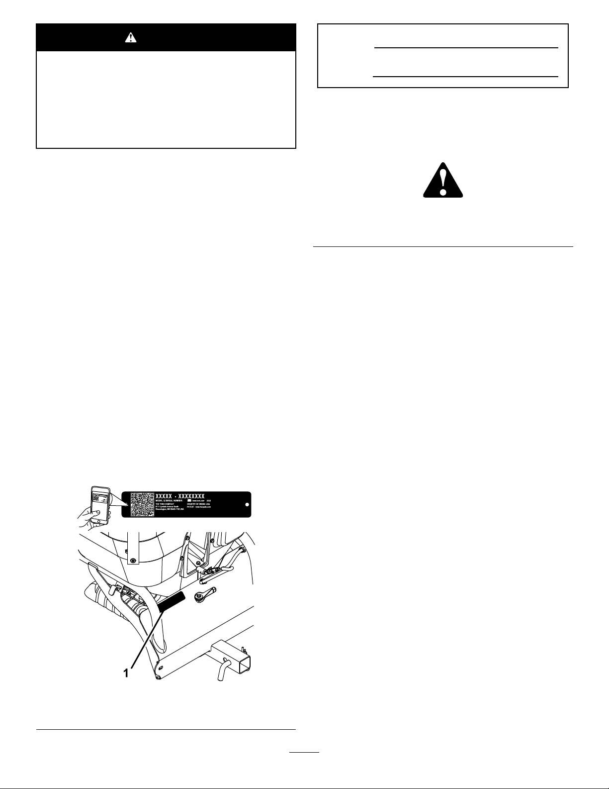
andserialnumbersofyourproductready.Figure1
identiesthelocationofthemodelandserialnumbers
ontheproduct.Writethenumbersinthespace
provided.
Important:Withyourmobiledevice,youcan
scantheQRcode(ifequipped)ontheserial
numberdecaltoaccesswarranty,parts,andother
productinformation.
Figure1
1.Locationofthemodelandserialnumbers
Contents
Safety.......................................................................3
SafeOperatingPractices....................................3
SafetyandInstructionalDecals..........................4
Setup........................................................................5
1PreparingtheMachine.....................................6
2InstallingtheFlowControlPanel......................6
3InstallingtheHopperAssembly........................6
4InstallingtheCable-MountBracket...................7
5InstallingtheControlCable..............................7
6InstallingtheWireHarness..............................9
7InstallingtheCover........................................10
ProductOverview....................................................11
Specications...................................................11
Operation.................................................................11
Controls.............................................................11
Pre-Start...........................................................12
OperatingInstructions......................................13
OperatingtheSpreaderAccessory...................13
OperatingTips..................................................16
RemovingtheSpreaderAttachment.................16
Maintenance...........................................................17
RecommendedMaintenanceSchedule(s)...........17
.............................................................................17
CheckforLooseHardware...............................17
SpreaderPatternControlCable
Adjustment....................................................17
g253435
AdjustingtheGateClosure...............................18
Cleaning..............................................................18
CleanDebrisFromMachine.............................18
Troubleshooting......................................................19
Schematics.............................................................20
©2018—TheToro®Company
8111LyndaleAvenueSouth
Bloomington,MN55420
Contactusatwww.Toro.com.
2
PrintedintheUSA
AllRightsReserved
Page 3

Safety
Improperuseormaintenancebytheoperatoror
ownercanresultininjury.T oreducethepotential
forinjury ,complywiththesesafetyinstructions,
andpayattentiontothesafetyalertsymbol,which
meansCaution,Warning,orDanger—personalsafety
instruction.Failuretocomplywiththeinstructions
mayresultinpersonalinjuryordeath.
SafeOperatingPractices
CAUTION
Themachinethatthespreaderaccessory
attachestoproducessoundlevelsin
excessof85dBAattheoperator’searand
cancausehearinglossthroughextended
periodsofexposure.
Wearhearingprotectionwhenoperating
thismachine.
•Inspecttheareawhereyouwillusetheequipment
andremoveallobjectsfromtheareabeforeusing
themachine.
Training
•ReadtheOperator'sManualforthemachineand
thisaccessoryandothertrainingmaterial.
Note:Iftheoperator(s)ormechanic(s)cannot
readthemanuallanguage,itistheowner's
responsibilitytoexplainthismaterialtothem.
•Becomefamiliarwiththesafeoperationofthe
equipment,operatorcontrols,andsafetysigns.
•Alloperatorsandmechanicsshouldbetrained.
Theownerisresponsiblefortrainingtheusers.
•Neverletchildrenoruntrainedpeopleoperateor
servicetheequipment.
Note:Localregulationsmayrestricttheageof
theoperator.
•Theowner/usercanpreventandisresponsible
foraccidentsorinjuriesoccurringtohimselfor
herself,otherpeople,ordamagetoproperty.
Preparation
•Donotmodifytheaccessory.
•Evaluatetheterraintodeterminewhataccessories
andattachmentsareneededtoproperlyand
safelyperformthejob.Useonlyaccessoriesand
attachmentsapprovedbythemanufacturer.
•Wearappropriateclothingincludingsafetyglasses,
substantialfootwear,andhearingprotection.Tie
backlonghair,securelooseclothing,anddonot
wearloosejewelry.
Operation
WARNING
Hands,feet,hair,clothing,oraccessoriescan
becomeentangledinrotatingparts.Contact
withtherotatingpartscancausetraumatic
amputationorseverelacerations.
•Donotoperatethemachinewithout
guards,shields,andsafetydevicesin
placeandworkingproperly.
•Keephands,feet,hair,jewelry,orclothing
awayfromrotatingparts.
•Operatethemachineonlyingoodvisibilityand
appropriateweatherconditions.Donotoperate
themachinewhenthereistheriskoflightning.
•Operatethemachineonlyinwell-litareas,keeping
awayfromholesandhiddenhazards.
•Beawareofweatherconditionsandcheckthat
spreaderpatternsandvolumearesuitable.
•Neveroperatethemachinewithdamagedguards,
shields,orcovers.Alwayshavesafetyshields,
guards,switchesandotherdevicesinplaceandin
properworkingcondition.
•Stoponlevelground,disengagedrives,engage
theparkingbrake(ifprovided),shutofftheengine,
andremovethekeybeforeleavingtheoperator's
positionforanyreason.
•Stopspreadingwhenmakingtightturnsto
minimizeunevendistributionpatternand
applicationrate.
•Reducetheweightoftheloadwhenoperating
onhillsandroughterraintoavoidtippingor
overturningthemachine.
•Materialloadscanshift.Thisshiftinghappens
mostoftenwhileturning,goingupordownhills,
suddenlychangingspeeds,orwhiledrivingover
roughsurfaces.Shiftingloadscancausethe
machinetotipover.
3
Page 4
•Whenoperatingwithaheavyload,reduceyour
speedandallowforsufcientstoppingdistance.
Useextracautiononslopes.
•Reducespeedandloadwhenoperatingonrough
terrain,unevenground,andnearcurbs,holes,and
othersuddenchangesinterrain.Loadsmayshift,
causingthemachinetobecomeunstable.
•Heavyloadsaffectstability.Reducetheweightof
theloadandyourspeedwhenoperatingonhills.
tostopbeforeadjusting,cleaningorrepairingthe
machine.
•Emptythehopperbeforetiltingthemachinefor
maintenanceandbeforestoring.
•Keepyourhandsandfeetawayfrommoving
parts.Ifpossible,donotmakeadjustmentswith
theengineand/ortheimpellerrunning.
•Keepallguards,shields,andsafetydevicesin
placeandinsafeworkingcondition.
MaintenanceandStorage
•Closethespreadergate,engagetheparking
brake,shutofftheengine,andremovethekeyor
disconnectsparkplugwire.Waitforallmovement
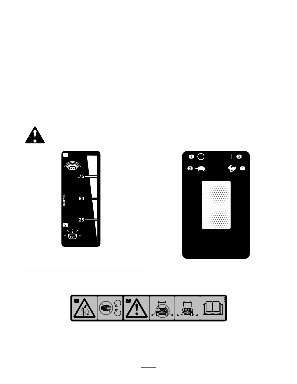
SafetyandInstructionalDecals
Safetydecalsandinstructionsareeasilyvisibletotheoperatorandarelocatednearanyarea
ofpotentialdanger.Replaceanydecalthatisdamagedormissing.
•Checkallboltsfrequentlytomaintainproper
tightness.
•Frequentlycheckforwornordeteriorating
componentsthatcouldcreateahazard.
135-0990
1.Spreadpattern-heavy2.Spreadpattern-light
1.Cutting/dismembermenthazard—keepawayfrommoving
parts.
decal135-0990
decal135-0739
135-0739
1.Impeller—off
2.Impeller—slow
126-4994
2.Warning—donotusetheupperfrontlocationsastiedown
points,onlyusethespeciedtie-downpoints;seethe
Operator’sManualforlocation.
4
3.Impeller—on
4.Impeller—fast
decal126-4994
Page 5

Setup
LooseParts
Usethechartbelowtoverifythatallpartshavebeenshipped.
ProcedureDescription
1
2
3
4
5
6
7
Nopartsrequired
Bolt(3/8x1-1/4inches)—30-inch
machinesonly
Locknut(1/4inch)—30-inchmachines
only
Bolt(1/4x5/8inch)—30-inchmachines
only
Bolt(5/16x3/4inch)—24-inchmachines
only
Locknut(5/16inch)—24-inchmachines
only
Hopperassembly1
Hairpincotter1
Hitchpin1
Cable-mountbracketfor24-inch
machines
Cable-mountbracketfor30-inch
machines
Carriagebolt(5/16x1inch)—24-inch
machinesonly
Carriagebolt(1/4x1inch)—24-inch
machinesonly
Locknut(1/4inch)—24-inchmachines
only
Locknut(1/4inch)—30-inchmachines
only
Bolt(1/4x5/8inch)—30-inchmachines
only
Controlcable
Locknut(1/4inch)
Washer2
Wireharness1
Cabletie
Cover
Washer4
Locknut(1/4inch)
Bolt(1/4x3/4inch)
Qty.
10
Use
–
1
1
1
3
3
1
1
1
1
1
2
2
1
2
1
4
4
Preparethemachine.
Installtheowcontrolpanel.
Installthehopperassembly .
Installthecable-mountbracket.
Installthecontrolcable.
Installtheharness.
InstallingtheCover
5
Page 6
1
PreparingtheMachine
NoPartsRequired
Procedure
1.Parkthemachineonalevelsurface.
2.Engagetheparkingbrake.
3.Shutofftheengineandremovethekey.
4.Disconnectthenegative(black)batterycable
fromthenegative(-)batteryterminal.
2
InstallingtheFlowControl Panel
Partsneededforthisprocedure:
1
Bolt(3/8x1-1/4inches)—30-inchmachinesonly
1
Locknut(1/4inch)—30-inchmachinesonly
1
Bolt(1/4x5/8inch)—30-inchmachinesonly
3
Bolt(5/16x3/4inch)—24-inchmachinesonly
3
Locknut(5/16inch)—24-inchmachinesonly
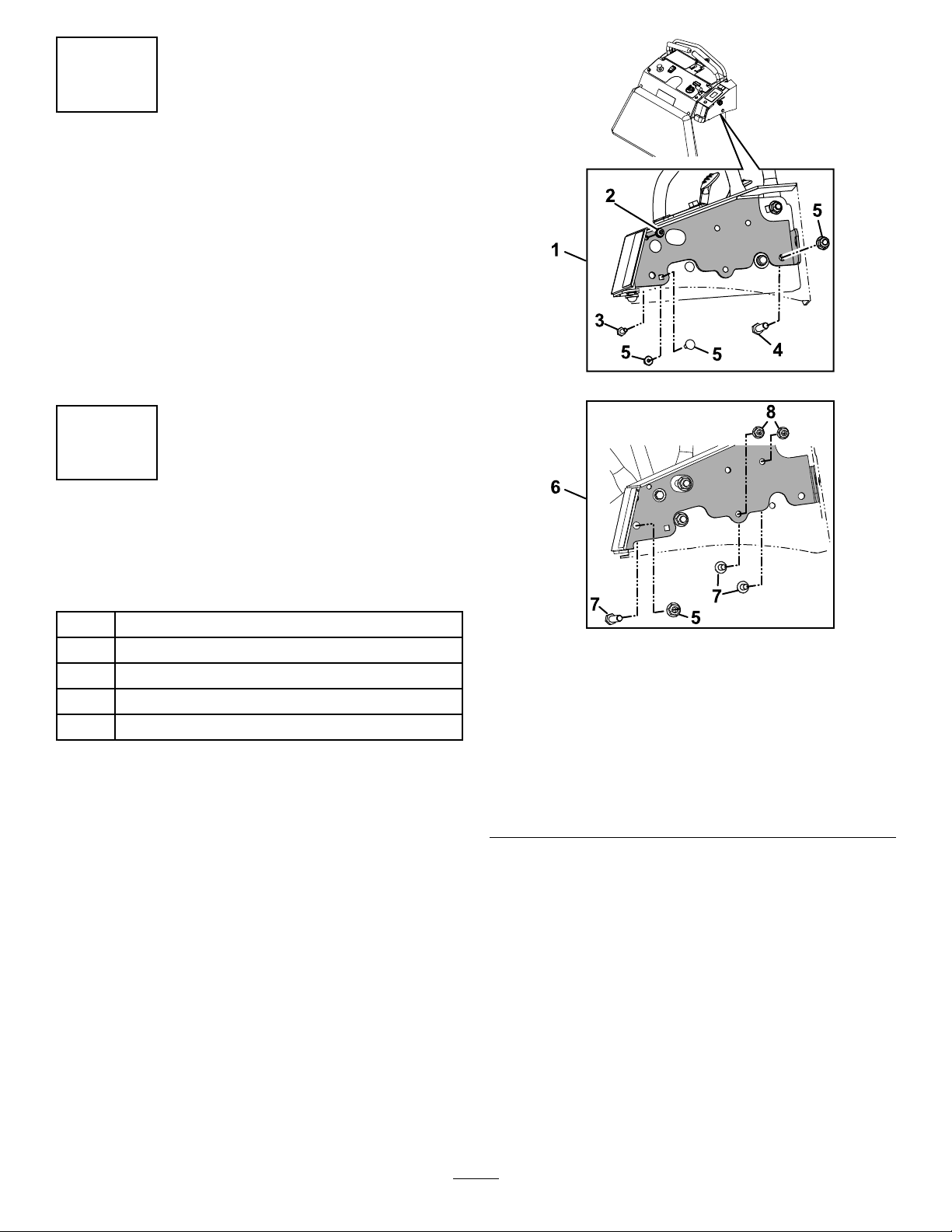
Procedure
1.Holdtheowcontrolpanelagainsttheright
sideofthemachinetodeterminethemounting
holeconguration.Removeandretainthe
mountinghardwarefromwherethebracketwill
beinstalledonthemachine.
Figure3
Outercoverhiddenforclarity
1.Installationfor30-inch
machine
2.Locknut(1/4inch)6.Installationfor24-inch
3.Bolt(1/4x5/8inch)7.Hex-headbolt(5/16x3/4
4.Bolt(3/8x1-1/4inches)8.Locknut(5/16inch)
2.Placetheowcontrolpanelontothemachine
andsecureitusingthehardwareshownin
Figure3.
Note:Additionalhardwareisshippedwiththe
spreaderiftheretainedhardwareisnotlong
enoughtomountthecontrolpanel.
5.Reuseretainedhardware
machine
inch)
g238611
6
Page 7

3
4
InstallingtheHopper
Assembly
Partsneededforthisprocedure:
1Hopperassembly
1Hairpincotter
1Hitchpin
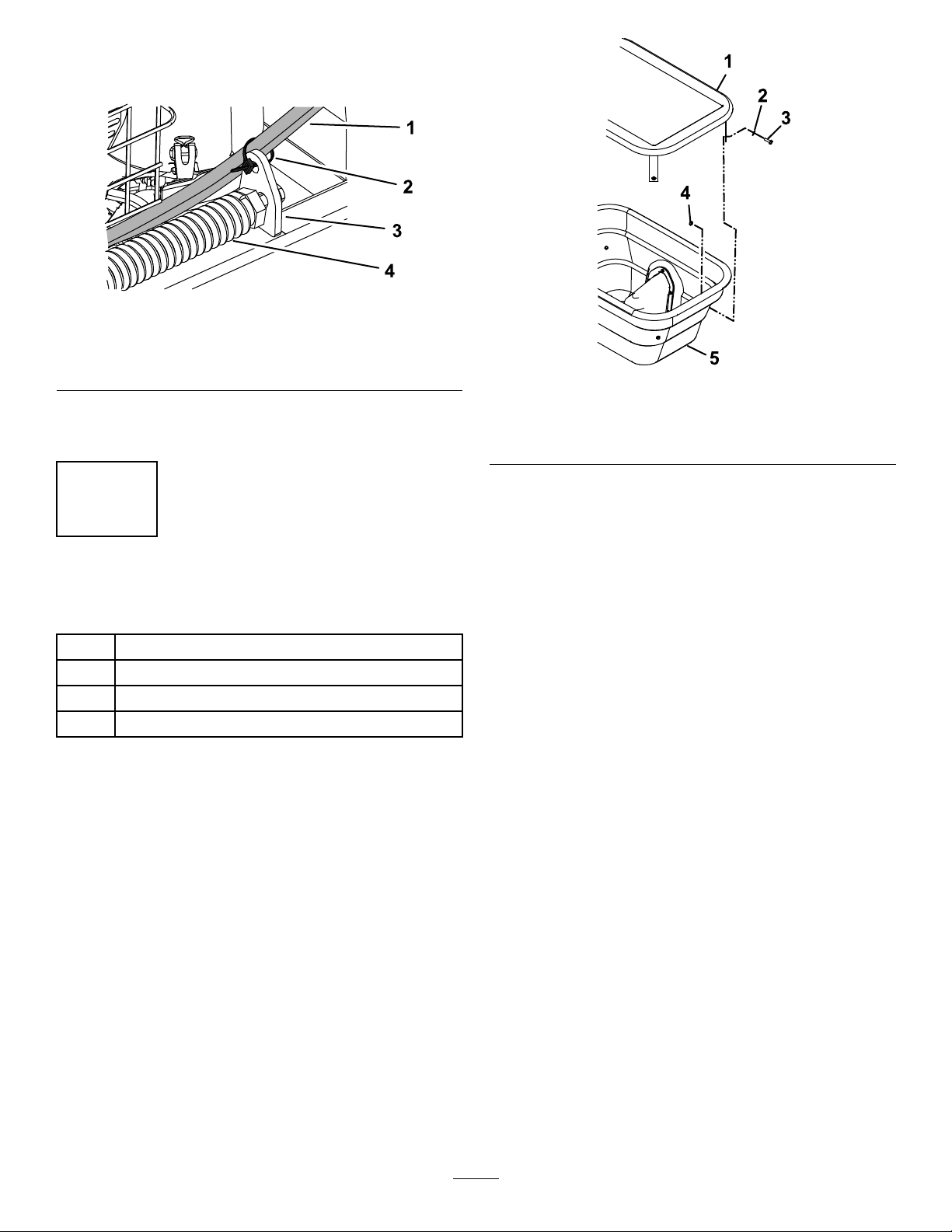
Procedure
1.Insertthehopperhitchtubeintothereceiveron
themachine.
InstallingtheCable-Mount Bracket
Partsneededforthisprocedure:
1
Cable-mountbracketfor24-inchmachines
1
Cable-mountbracketfor30-inchmachines
1
Carriagebolt(5/16x1inch)—24-inchmachinesonly
1
Carriagebolt(1/4x1inch)—24-inchmachinesonly
1
Locknut(1/4inch)—24-inchmachinesonly
2
Locknut(1/4inch)—30-inchmachinesonly
2
Bolt(1/4x5/8inch)—30-inchmachinesonly
Procedure
Choosetheappropriatecable-mountbracketby
matchingtheholestotherightsideofthemachine.
UsethehardwareshowninFigure5toinstallthe
bracket.
Figure4
1.Hopperhitchtube
2.Hitchpin
2.Usethehitchpinandhairpincottertosecurethe
hopperassemblytotheaerator.
3.Cotterpin
g213510
g213563
Figure5
1.Bracketfor30-inchaerator5.Carriagebolt(5/16x1
2.Bolt(1/4x5/8inch)
3.Locknut(1/4inch)7.Carriagebolt(1/4x1inch)
4.Bracketfor24-inchaerator8.Locknut(1/4inch)
inch)
6.Removeandusethisnut
tomountthebracket.
7
Page 8

5
InstallingtheControlCable
Partsneededforthisprocedure:
1
Controlcable
2
Locknut(1/4inch)
2Washer
Procedure
1.Ensuringthatthecableballjointissecurely
attachedtothecable,connecttheballjointto
thecontrolarmandsecureitwithawasherand
locknut(1/4inch)asshowninFigure6.
Figure6
g213569
Figure7
1.Locknut(1/4inch)4.Cableend
2.Washer5.Hopperbracket
3.Gatearm
4.Insertthecableendintotheholeofthegate
arm;securethecableendwithawasherand
locknut(1/4inch);seeFigure7.
5.Loosenthenutsoneachsideofthecontrolcable
andslideitintothenotchofthehopperbracket.
Tightenthenutsoneachsideofthebracket.
6.Movetheowcontrolleverforwardand
rearward,makingsurethatthegatearmfully
opensandcloses.Ifitdoesnotclose,loosen
theknoband/ornutstoadjustthecableuntilthe
gatecanbefullyclosed;tightenallcomponents.
Makesurethatthejamnuthasbeensecurely
tightenedagainstthecableballjointafterall
adjustmentshavebeenmade(seeFigure6).
g221603
1.Cableballjoint
2.Controllever
3.Locknut(1/4inch)
4.Cable-mountbracket
2.Loosentheknobandslidethecontrolcableinto
thenotchofthemountbracketandtightenthe
knob.
3.Routetheotherendofthecontrolcabletothe
gatearm.
5.Knob
6.Washer
7.Jamnut
8
Page 9

6
InstallingtheWireHarness
Partsneededforthisprocedure:
bracketandhoppertube.Connectthespreader
harnesstothespreadermotorasshownin
Figure8.Insertthe3harnesstieclipsintothe
holesofthehoppermainframetosecurethe
harness.
4.Removethecapfromtheaccessorywireon
themainharnessandplugintothespreader
accessoryharnessasshowninFigure9.
1Wireharness
10
Cabletie
Procedure
Important:Besurethemachineisnotrunning
andthekeyhasbeenremovedfromtheignition
switchpriortoproceedingwiththeharness
installation.
1.Disconnectthebattery;refertoyourOperator’s
Manual.
2.PlugthehourmeterandON/OFFconnectorson
thespreaderharnessintotheswitchesonow
controlpanel(seeFigure8).
24InchModelsOnly:Removetheadaptor
plugfromthemainaccessoryharness.
Figure8
1.Harness
2.Hourmeterconnector4.Motorconnector
3.Routetheharnessalongtherightsideofthe
machine,followingthecontrolcable.Placethe
harnessontopofthecontrolcableandslideit
intothenotchofthehopperbracket.Continue
toroutetheharnessbetweentherighthopper
3.On/offswitch
g213882
Figure9
1.Spreaderharness
2.Accessoryplug
3.Battery
4.Positivebatteryterminal
5.Spreaderharnesspositivebatteryconnection
6.Spreaderharnessnegativebatteryconnection
7.Negativebatteryterminal
g213636
5.Removeandretainthenutandscrewfrom
thepositiveterminalonthebattery.Installthe
accessoryharnesspositivecable(secondtolast
terminalring—seeFigure9)andthepositive
cableofthemainharnesstothefrontofthe
positivebatteryterminalandsecurewiththenut
andscrew.Repeatfornegativebatterycable.
6.Usetheedgecliptosecuretheharnesstothe
rightaeratorpanel.
9
Page 10
7.For24-inchmachines,use1cabletietosecure
thecableandharnesstothespringorspring
mount.
Figure10
1.Cableandharness3.Springmount
2.Cabletie4.Spring
g253434
g221638
Figure11
8.Usetheremainingcabletiestosecurethe
harnesstotheframeand/orcontrolcable.
7
InstallingtheCover
Partsneededforthisprocedure:
1
Cover
4Washer
4
Locknut(1/4inch)
4
Bolt(1/4x3/4inch)
Procedure
1.Attachthecovertothehopperin2placesby
insertingabolt(1/4x3/4inch)andwasher
throughthecovertabgrommetandhopperas
showninFigure11.
1.Cover3.Bolt(1/4x3/4inch)
2.Washer
2.Securewithalocknut(1/4inch).
3.Plugtheother2holesinthehopperwith
remaininghardware.
4.Locknut(1/4inch)
10
Page 11

ProductOverview
Figure12
1.Controls
Specications
Width
Length
Height
Weight
Maximumhoppercapacity
Spreadingwidth1.2to6.7m(4to22ft)
2.Hopper
69cm(27inches)
81cm(32inches)
71cm(28inches)
32kg(70lb)
36kg(80lb)
Operation
Note:Determinetheleftandrightsidesofthe
machinefromthenormaloperatingposition.
Important:Theintendeduseofthisspreader
attachmentisfordispersinggrassseed.Thisis
nottobeusedforfertilizeroranyotherchemical
applications.
Controls
ImpellerSpeedControl
Locatedatthetopofthespreaderaccessorycontrol
g228584
panel(seeFigure13).
Pushdownontherightsideoftheswitch1timeto
turnthespreader“ON”;continuetotaptherightside
toincreasetheimpellerspeed.
Taptheleftsideofthecontroltodecreasethespeed;
pushandholdtheleftsideoftheswitchtoturnit
“OFF”.
Note:Theimpellerspeedcontrolcanbeturnedoff
atanyspeedrate.Itisnotnecessarytodecreasethe
speeduntilitturnsoff.Thelastsetspeeddisplays
whenthecontrolispoweredbackon.
Figure13
1.Impellerspeedcontrol3.Distributionlimitlockknob
2.Impellerspeeddisplay4.Flowcontrollever
ImpellerSpeedDisplay
Locatedbelowtheimpellerspeedcontrol.
Thisdisplayshowsthespeedsettingnumberfrom1
to10(1istheslowestspeedand10isthefastest).A
circledisplayswhenthecontrolhasbeenturnedoff.
11
g207672
Page 12
FlowControlLever
Locatedtotherightofthemaincontrols.
Lifttheleverupwardtostarttheowandcontinue
liftingittoincreasethedistributionrate.Pullthelever
downwardtodecreaseorstopthedistributionrate.
DistributionLimitLockKnob
Locatedontherightpanelofthespreaderaccessory
controlpanel.
Thisknobisusedtolimitthemaximumamount
ofgrassseedbeingdispensedtohelpmaintain
consistentdistribution.
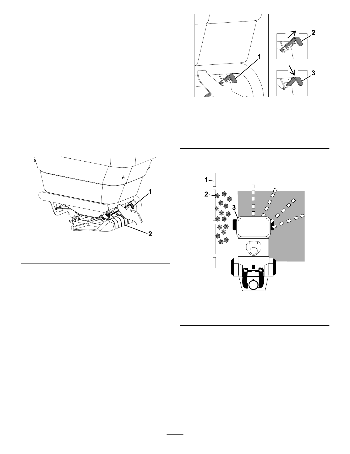
SideDeectorControlLever
Locatedontheleftsideofthehopper(seeFigure14).
g208735
Figure15
LeverPositions
1.Sidedeectorraises
2.Pullleveroutward
3.Pushdown—sidedeectorlowers
Toraisethedeector,lifttheleverintothewideportion
oftheslotandpushtheleverinwarduntilitstops.
Figure14
1.Sidedeectorcontrollever2.Sidedeector
Usethesidedeectorcontroltotemporarilystopor
deectgrassseedawayfromsidewalks,parkinglots,
patios,oranywheregrassseedisnotdesiredtobe
dischargedfromtheleftsideofthespreader.
Totemporarilydeectthegrassseed,lifttheleverup
andpulloutwarduntilthenotchcanbeseatedinto
thelowernarrowportionofthebracket;sidedeector
lowers(seeFigure15).
g207876
g207826
Figure16
1.Fence
2.Flowers
3.Sidedeectorlowered
Pre-Start
Ensurethatyouunderstandthecontrols,their
locations,theirfunctions,andtheirsafety
requirements.
Ensurethatthehopperanditscomponentsarein
goodcondition,properlyattached,andlatched.
12
Page 13

OperatingInstructions
CAUTION
Machinecanspinveryrapidlybypositioning
1levertoomuchaheadoftheother.Operator
maylosecontrolofthemachine,whichmay
causedamagetothemachineorinjury .
•Usecautionwhenmakingturns.
•Slowthemachinedownbeforemaking
sharpturns.
Note:Thestoppingdistancemayvarydependingon
thespreaderload.
OperatingtheSpreader Accessory
Thespreaderaccessoryisdesignedtodispersegrass
seed.
BeforeOperatingtheSpreader
Ensurethatthespreaderhasbeencalibratedforthe
correctapplicationrateofthegrassseedtobespread
beforestarting(seeCalculatingtheApplication
Ratesection).
FillingtheSpreaderHopper
Important:Verifythattheproperapplicationrate
hasbeensetpriortollingthehopper.
1.Parkthemachineonalevelsurface,movethe
motion-controllevertotheneutralposition,shut
offtheengine,removethekey,andengagethe
parkingbrake.
2.Ensurethatthespreadergateisclosed.
3.Removethecoverfromthehopper,addthe
grassseedtobespread,andreplacethecover.
Note:Donotoverloadthehopper;the
maximumweightcapacityofthehopperis36
kg(80lb).
CalculatingtheApplicationRate
1.Determinethekg(lb)per93m
producttobeapplied.
2.Determinethecalibrationcourse:
2
(1,000ft2)of
A.Determinetheamountofproducttobe
spreadper93m
recommendedratefromtheSpreading
Chartsectionortheproductmanufacturer’s
labelasaguide.
B.Determineacourselengthbydividing93
2
m
(1,000ft2)bytheeffectivespreadwidth.
Forexample,iftheeffectivewidthis1.8
m(6ft),thenthecalibrationcourselength
equals51m(167ft).
2
(1,000ft2).Usethe
CourseLength
93m2(1,000ft2)
1.8m(6ft)
C.Thecalibrationcourseis1.8m(6ft)by51
m(167ft).
D.Measureandvisiblymarkthecourselength.
Makesuretoallowampledistancebefore
thestartingmarkertoensurethespreader
isatfullspeedwhencrossingtherstmark
ofthecourse.
3.Settheappropriategatesetting(referencethe
SpreadingChartsectionasastartingpoint).
4.Addgrassseedtothehopper(forexample,11.3
kg(25lb)wasadded).
5.Drivethespreaderoverthecalibrationcourse
whileapplyingthegrassseed.
6.Emptytheremaininggrassseedofthehopper
intoacleanbucket.
7.Weighthebucketcontainingthegrassseedand
recordtheweight.Pourthecontentsbackinto
thehopperandthenweightheemptybucket.
Subtractthese2amountstodeterminethe
amountofgrassseedremaininginthehopper
(forexample,9kg(20lb)remains).
8.Subtracttheamountremaininginthehopper
(step7)fromtheamountoriginallyadded(step
4);theresultistheamountappliedtothecourse.
=
51m(167ft)
AmountApplied
11.3kg–9kg(25lb–20lb)
Forthisexample,2.3kg(5lb)wasappliedto
2
93m
9.Ifnecessary ,adjusttheratelevertoachievethe
recommendedamounttobeappliedandrepeat
theprocedure.Oncethecorrectapplicationrate
isachieved,repeatthisprocedureanadditional
timetoverifytheresults.
(1,000ft2).
=
5lb(2.3kg)
SpreadingChart
Thechartbelowisforreferenceonly.
13
Page 14

GrassSeedApplicationatMaximumGroundSpeed
Type
BlueGrassorRedT op0.9kg(2lb)
Park,Merion,Delta,orKentucky
Bluegrass
HulledBermuda
MixturesIncludingCoarseSeeds2.7kg(6lb)
RyeGrassesorTallFescue2.7kg(6lb)
Dichondra
PensacolaBahia
kg(lb)/93m
(Coverage93m
0.2kg(0.5lb)
0.9kg(2lb)
0.3kg(0.75lb)
2.7kg(6lb)
2
(1,000ft2)GateOpeningSpreadWidth
2
or1,000ft2)
.25
.25
.75
.75
.75tomaximumopen
.25
.50
1.2m(4ft)
1.2m(4ft)
1.8m(6ft)
1.8m(6ft)
1.8m(6ft)
2.4m(8ft)
2.1m(7ft)
Spreading
SpreadingTips:
•Toensureuniformapplication,besuretooverlapthegrassseeddistribution.Thehighestamountof
seeddispensesfromthefrontofthehopperandlessfromeachside.Adjustthedistributionpatternto
achievedesiredresults.
•Watchforchangesinthedistributionpattern;unequaldistributionmayleadtostriping.
Figure17
1.Narrowdistribution-sidedeectorlowered5.Endofspreadingjob
2.Forward
3.Effectivespreadingwidth—variable1.2to6.7m(4to22ft)7.Gate
4.Donotspreadwhenturning180degrees
6.Propertyfence
1.StarttheengineandplacethethrottlemidwaybetweentheSLOWandFASTpositions.
2.Turnontheimpellerspeedcontrol.
3.Settheimpellerspeedtotheappropriatesetting.
14
g207791
Page 15

4.MovethethrottletotheFASTpositionanddriveforward.
5.Openthehoppergateandbeginspreading.
1.Effectivespreadingwidth—variable1.2to6.7m(4to22ft)
g207728
Figure18
6.Evaluatethespreadpattern.IfadjustmentsareneededseetheSpreaderPatternAdjustmentsection.
7.Whennishedspreading,closethehoppergate.
15
Page 16

SpreaderPatternAdjustment
Ifthespreadpatternisskewedordispensingtoo
light/heavyto1side(Figure19),adjustthegateas
follows:
OperatingTips
Overseeding
Important:Donotputdownmoreseedthan
recommendedbytheseedcompany.Overseeding
cancausethegrasstobetoothickandcauseitto
besusceptibletofungus.
Note:Themachineseedsatthesamerategoing
bothforwardandrearward.
Note:Ifthereisexcessivethatch,itmaybe
necessarytoremovethethatchpriortoseeding.
Figure19
1.Heavytoleftside
2.Moveramppatternto
shadedposition
3.Heavytorightside
Note:Donotadjusttherampstosplitproductow.
Useonlythefrontorrearramppositionsasshown.
1.Unlockthespreaderpatterncontrolknobby
turningitcounterclockwise90degrees.
g025543
RemovingtheSpreader Attachment
1.Shutofftheengine,removethekey,waitforall
movingpartstostop,engagetheparkingbrake,
andremovethekey.
2.Unplugthespreaderaccessoryharness
(referenceFigure9).
3.Disconnectthecableballjointfromthecontrol
lever(referenceFigure6).Loosentheknobon
thecablemountbracket.
4.Removeandretainthehitchpinfromthe
receiver(referenceFigure4)
5.Removethehopperassembly,controlcable,
andaccessoryharness.
Note:Allotherspreaderattachment
componentsmaystaymountedonthemachine.
Makesurecomponentsaresecureandaway
frommovingparts.
Figure20
1.Spreaderpatterncontrol
knob
Toadjustwhenthegrassseedpatternisheavy:
2.Controlhandle
•Totheleftside,slightlypullthecontrolhandle
rearward.
•Totherightside,slightlypushthecontrol
handleforward.
2.Lockthespreaderpatterncontrolbyturningthe
controlknobclockwise90degrees.
g207877
16
Page 17

Maintenance
Note:Determinetheleftandrightsidesofthemachinefromthenormaloperatingposition.
WARNING
Ifyouleavethekeyintheswitch,someonecouldaccidentlystarttheengineandseriously
injureyouorotherbystanders.
Removethekeyfromtheswitch,engageparkingbrake,andpullthewire(s)offthespark
plug(s)beforeyoudoanymaintenancetothemachineorattachment.Alsopushthewire(s)
asidesoitdoesnotaccidentallycontactthesparkplug(s).
RecommendedMaintenanceSchedule(s)
MaintenanceService
Interval
Beforeeachuseordaily
MaintenanceProcedure
•Checkforloosehardware.
•Cleanthedebrisbuildupfromthemachine.
CheckforLooseHardware
ServiceInterval:Beforeeachuseordaily
1.Shutofftheengine,waitforallmovingpartsto
stop,andremovethekey.Engagetheparking
brake.
2.Visuallyinspectthemachineforanyloose
hardwareoranyotherpossibleproblem.Tighten
anyloosehardwareorcorrecttheproblem
beforeoperatingthemachine.
SpreaderPatternControl CableAdjustment
Toadjustthespreaderpatterncontrolcable:
1.Shutofftheengine,waitforallmovingpartsto
stop,andremovethekey.Engagetheparking
brake.
2.Closethegranulargate.
3.Ensurethatthespreadpatterncontrolhandleis
pusheddownandlockedatthecontrolpanel.
4.Loosenthejamnutattheendofthecable.
g027205
Figure21
1.Jamnut
2.Linkagerod
3.Impellershaft
4.3.2mm(1/8inch)gapbetweenramptoothandimpeller
shaft
5.Ramptooth
5.Pullthelinkageroduntilthereis3.2mm(1/8
inch)gapbetweentheramptoothandthe
impellershaft.
6.Tightenthejamnut.
17
Page 18

AdjustingtheGateClosure
1.Ifthegatearmisnotfullyclosing,adjustthe
controlcable:
•Knoblocatedonthecablemountbracket
•Nutslocatedoneithersideofthehopper
bracket
2.Continuetoadjustuntilthegatecanbefully
closed;tightenallcomponents.
Cleaning
CleanDebrisFromMachine
ServiceInterval:Beforeeachuseordaily
1.Shutofftheengine,waitforallmovingpartsto
stop,andremovethekey.Engagetheparking
brake.
2.Cleanoffanydebrisorbuilduponthemachine,
especiallytheimpeller.
18
Page 19

Troubleshooting
Thefollowingtablelistssomeofthecommoncausesoftrouble.Ifaproblemcontinues,contactanAuthorized
ServiceDealer.
Problem
Messagedisplays“STALLED(02)”1.Controllerhasdetectedanexcessive
Messagedisplays“WIREFAULT(04)”
Messagedisplays“WIREFAULT(05)”1.Oneoftwooutputsarenotproviding
Messagedisplays“WIREFAULT(06)”
Thecontrollerdoesnotpoweron.
Thecontrollerfailstokeeprunning.
electricalcurrenttotheimpellermotor.
1.Thecontrollerisunabletodetectmotor
feedbackvoltage.
powertotheimpellermotor.
1.Thecontrollerisunabletodetect
connectiontotheimpellermotor .
1.Afuseisblown.1.Replacetheblownfuse.
2.Thereareimproperelectrical
connections.
3.Thecontrollermoduleisfaulty.
1.Electricalconnectionsarecorroded,
loose,orfaulty.
PossibleCauseCorrectiveAction
1.Checktheimpellerandhopperfor
obstructionsthatmayaddanexcessive
loadtotheimpellermotor.Checkthe
electricalconnectionstotheimpeller
motortoensuretheyarenotshorted.
Pressthe“ON”switchtoretry.
1.Checkpins18onthecontroller
connectorforproperpinseatingand
locking.
1.Checkpins6and8onthecontroller
connectorforproperpinseatingand
locking.
1.Powerofftheimpellerandcheckthe
electricalconnectionstotheimpeller
motor.
2.Checktheelectricalconnectionsat
theaccessorypowerconnectorand
batteryringterminalsandensureboth
havepower .
3.Replacethecontrollermodule.
1.Checktheelectricalconnections
forgoodcontact.Cleanconnector
terminalsthoroughlywithelectrical
contactcleaner,applydielectricgrease
andreconnect.
Aswitchisunresponsive.
1.Theswitchconnectormaybeloose.1.Ensurethattheswitchconnectoris
2.Pinsmaynotbeinsertedintothe
correctterminals.
connectedtotherockerswitch.
2.Checkforincorrectpinpositions.
19
Page 20

Schematics
M
BT01
TERMINAL +
TERMINAL -
BATTERY
DIS01
CONTROLLER - MOTOR DRIVE
B+
NC
NCSW PWR
NC
NC
OUTPUT ENABLE
NC
NC
MOTOR IN
NC
MOTOR OUT 1
MOTOR OUT 2
UP SW
NC
DOWN SW
NC
GND
CAN LO
CAN HI
P04
121420
5
6
8
1
18
17
15
P04
3
4
7
16
111319
2
9
10
Motor+
Motor-
SPREADER MOTOR
M01
P07
A
B
NC
CAN HI
CAN LO
SW PWR
FUSED PWR
GND
CAP03
DUST CAP
P02
12345
6
D01
DIODE
P05
B
P05
A
J02
F01 20A
Motor Power
RED RED/GREEN
BLACK
BLACK
BLACK
BLACK
BROWN/WHITE
VIOLET/RED
BLACK
VIOLET/BLACK VIOLET
WHITE/BLACK
WHITE/TAN
BLACK
BLACK
BLACK
BLACK
ORANGE
RED/WHITE
RED/WHITE
GREEN
GREEN
YELLOW
YELLOW
RED/GREEN
RED/GREEN
RED/WHITE
PINK
BLACK
VIOLET/WHITE
SP01
SP02
SP03
SP04
SP05
SP06
SP07
MINI FUSE HOLDER CAP
P03P03
BA
P08
A
B
P09
A
B
BLACK
VIOLET/RED
P01
ACC CONNECTOR
A
B
C
ACC PWR ADAPTER
GND
SW PWR
A
B
S01
DOWN
(ON)-OFF-(ON)
UP
P06
1
3
4
6
8
P06
2
5
7
J01
g212875
ElectricalSchematic(Rev .A)
20
 Loading...