


FormNo.3421-778RevA
Groundsmaster
®
1200SeriesPull
BehindRotaryMower
ModelNo.31905—SerialNo.400000000andUp
Registeratwww.T oro.com.
OriginalInstructions(EN)
*3421-778*A

ThisproductcomplieswithallrelevantEuropean
directives;fordetails,pleaseseetheseparateproduct
specicDeclarationofConformity(DOC)sheet.
Thismachinehasbeendesignedinaccordancewith
ANSIB71.4-2012.
WARNING
CALIFORNIA
Proposition65Warning
Useofthisproductmaycauseexposure
tochemicalsknowntotheStateof
Californiatocausecancer,birthdefects,
orotherreproductiveharm.
g249978
Figure1
1.Modelandserialnumberlocation
ModelNo.
SerialNo.
Introduction
Thismachineisintendedforusebyprofessional,
hiredoperatorsincommercialapplications.Itis
designedformowinggrassonwell-maintained
lawnsinparks,golfcourses,sportselds,andon
commercialgrounds.
Important:Readthisinformationcarefullyto
learnhowtooperateandmaintainyourproduct
properlyandtoavoidinjuryandproductdamage.
Youareresponsibleforoperatingtheproduct
properlyandsafely.
Visitwww.Toro.comforproductsafetyandoperation
trainingmaterials,accessoryinformation,helpnding
adealer,ortoregisteryourproduct.
Wheneveryouneedservice,genuineToroparts,or
additionalinformation,contactanAuthorizedService
DealerorToroCustomerServiceandhavethemodel
andserialnumbersofyourproductready.Figure1
identiesthelocationofthemodelandserialnumbers
ontheproduct.Writethenumbersinthespace
provided.
Thismanualidentiespotentialhazardsandhas
safetymessagesidentiedbythesafety-alertsymbol
(Figure2),whichsignalsahazardthatmaycause
seriousinjuryordeathifyoudonotfollowthe
recommendedprecautions.
g000502
Figure2
1.Safety-alertsymbol
Thismanualuses2wordstohighlightinformation.
Importantcallsattentiontospecialmechanical
informationandNoteemphasizesgeneralinformation
worthyofspecialattention.
Important:Withyourmobiledevice,youcan
scantheQRcodeontheserial-numberdecal(if
equipped)toaccesswarranty,parts,andother
productinformation.
©2018—TheToro®Company
8111LyndaleAvenueSouth
Bloomington,MN55420
Contactusatwww.Toro.com.
2
PrintedintheUSA
AllRightsReserved

Contents
Safety
Safety.......................................................................3
GeneralSafety...................................................3
SafetyandInstructionalDecals..........................4
Setup........................................................................6
1ApplyingtheEntanglementDecal....................6
2InstallingtheDeckCoverKnobs.......................7
3AdjustingtheDrawbarPositionoftheT ow
Vehicle............................................................7
4AdjustingtheT owBaroftheMower..................7
5ConvertingthePinT owBartoaPintleTow
Bar..................................................................8
6RoutingtheDeck-LockRopeatthe
Mower.............................................................8
ProductOverview...................................................10
Specications...................................................11
Attachments/Accessories..................................11
BeforeOperation..................................................11
BeforeOperationSafety....................................11
TractorControls................................................12
OutcrossTractionUnitControls........................12
PTOSpeed.......................................................12
TrainingPeriod.................................................12
CheckingtheTireAirPressure..........................12
CheckingthePTOandDriveShaft
Guards..........................................................13
UsingtheT owBarJack.....................................14
AssemblingtheMowertotheT ow
Vehicle..........................................................15
DuringOperation.................................................19
DuringOperationSafety...................................19
SlopeSafety.....................................................20
LoweringtheMowerDecksfromthe
TransportPosition.........................................20
RaisingtheMowerDeckswhileCutting
Grass............................................................21
RaisingtheMowerDeckstotheTransport
Position.........................................................21
AdjustingtheHeight-of-Cut...............................22
MakingaSharpTurn........................................23
AfterOperation....................................................24
AfterOperationSafety......................................24
CleanandInspect.............................................24
Tie-DownPoints...............................................24
TransportingtheMachine.................................24
Maintenance...........................................................25
RecommendedMaintenanceSchedule(s)...........25
LiftingtheMower..............................................26
AccessingtheMowerDecks.............................26
Lubrication........................................................27
ServicingtheGearboxes..................................30
CheckingtheMowerBelts................................33
ReplacingtheMowerBelts...............................33
ServicingtheBlades.........................................35
AdjustingtheMowerPitch................................39
Storage...................................................................41
StoringtheMachine..........................................41
GeneralSafety
Thisproductiscapableofamputatinghandsand
feetandofthrowingobjects.Alwaysfollowallsafety
instructionstoavoidseriouspersonalinjury.
Usingthisproductforpurposesotherthanitsintended
usecouldprovedangeroustoyouandbystanders.
•Readandunderstandthecontentsofthis
Operator’sManualbeforeusingthemower.
•Useyourfullattentionwhileoperatingthetow
vehicleandmower.Donotengageinanyactivity
thatcausesdistractions;otherwise,injuryor
propertydamagemayoccur.
•Donotputyourhandsorfeetnearmoving
componentsofthemachine.
•Donotoperatethemowerwithoutallguards
andothersafetyprotectivedevicesinplaceand
workingonthemachine.
•Keepclearofanydischargeopening.Keep
bystandersandpetsasafedistanceawayfrom
themower.
•Keepchildrenoutoftheoperatingarea.Never
allowchildrentooperatethetowvehicleorthe
mower.
•Stopthemachine,engagetheparkingbrake,
shutofftheengine,removethekey,andwait
forallmovingpartstostopbeforeservicingor
uncloggingthemower.
Improperlyusingormaintainingthismowercanresult
ininjury .T oreducethepotentialforinjury,complywith
thesesafetyinstructionsandalwayspayattention
tothesafety-alertsymbol
Warning,orDanger—personalsafetyinstruction.
Failuretocomplywiththeseinstructionsmayresultin
personalinjuryordeath.
,whichmeansCaution,
3

SafetyandInstructionalDecals
Safetydecalsandinstructionsareeasilyvisibletotheoperatorandarelocatednearanyarea
ofpotentialdanger.Replaceanydecalthatisdamagedormissing.
110-4668
1.Entanglementhazard,shaft—stayawayfrommovingparts.
2.PTOspeedandinputdirection.
3.Usecliptosecurelashcablewhennotinuse.Uselash
cabletosupportthepowertake-offwhenthemachineis
disconnectedfromtractor.
decal110-4668
117-4979
1.Entanglementhazard,belt—keepawayfrommovingparts;
keepallguardsandshieldsinplace.
119-6807
1.Warning—nostep
120-0625
1.Pinchpoint,hand—keephandsaway.
decal117-4979
decal120-6604
120-6604
1.Thrownobjecthazard—keepbystandersawayfromthe
machine.
2.Cutting/dismembermenthazardofhand,mower
blade—stayawayfrommovingparts;keepallguardsand
shieldsinplace.
3.Cutting/dismembermenthazardoffoot,mowerblade—stay
awayfrommovingparts;keepallguardsandshieldsin
place.
decal119-6807
decal120-0625
decal125-6110
125-6110
1.Crushinghazard—donotstandunderanypartofthe
machine.
decal133-8061
133-8061
4

decal138-3078
138-3078
1.Beltrouting
decal138-3087
138-3087
5

Setup
LooseParts
Usethechartbelowtoverifythatallpartshavebeenshipped.
ProcedureDescription
1
2
3
4
5
6
MediaandAdditionalParts
Description
Operator'sManual
Qty.
CEentanglementdecal
Knob6Installthedeckcoverknobs.
Nopartsrequired
Nopartsrequired
Nopartsrequired
Nopartsrequired
Qty.
1
Readthismanualbeforeusingthepullbehindrotary
mower.
1
–
–
–
–
Applytheentanglementdecal—CE
mowers
Adjustthedrawbarpositionofthe
machine.
Adjustthetowbarofthemower
Convertthepintowbartoapintletow
bar.
Routethedecklatchropeatthemower.
Use
Use
1
ApplyingtheEntanglement Decal
CEMowers
Partsneededforthisprocedure:
1
CEentanglementdecal
Procedure
Important:ThisprocedureisrequiredforallCE
countriesandanywhereEnglishiscommonly
spoken.
1.RotatethePTOshaftguardtoaccessthe
existingentanglementdecal(Figure3).
g262546
Figure3
1.Existingentanglement
decal
2.CEentanglementdecal
6

2.Cleantheexistingentanglementdecalandthe
guardareasurroundingthedecal.
3.RemovethebackingfromtheCEentanglement
decal.
4.PlacetheCEentanglementdecaloverthe
existingentanglementdecal(Figure3).
2
InstallingtheDeckCover Knobs
Non-CEMowers
Partsneededforthisprocedure:
6Knob
Procedure
1.Removethemowerdeckcovers;referto
RemovingtheDeckCovers(page26).
2.Removethepush-nutthatsecurestheboltto
thedeckcoverandremovetheboltfromthe
cover(Figure4).
3
AdjustingtheDrawbar PositionoftheTowVehicle
NoPartsRequired
Procedure
Adjustthedrawbar(Figure5)ofthetowvehicleto
theextendedposition;refertotheOperator’sManual
foryourtowvehicle.
g250235
Figure5
1.Drawbar(extendedposition)
Figure4
1.Bolt3.Push-nut
2.Deckcover
3.Installthemowerdeckcoverwiththeknob;refer
toInstallingtheDeckCovers(page27).
4.Repeatsteps1through3fortheremainingdeck
covers,
4
AdjustingtheTowBarof theMower
NoPartsRequired
g264078
AssessingtheJobSite
Considerthefollowingjobsiteconditionstodetermine
thetowbarpositionofthemower:
•Turfwithhillsanddipsinthecontour—setthetow
bartoashorterlength.
•Turfthatisprimarilyat—setthetowbartoa
longerlength.
Note:Youmayneedtotryanintermediateposition
tow-barlengthwhenjobsitehasamixtureofatand
hillyareas.
7

AdjustingtheTow-BarLength
Note:Thetowbarofthemowerhas5tow-bar
positionsallowingyoutoadjustthelength20cm(8
inches).
1.Removethe2angelocknuts,2capscrews,
and2washersthatsecurethehitchtubetothe
receivertube(Figure6).
Figure6
1.Hitchtube4.Flangenut
2.Capscrew
3.Washer
5.Receivertube
5
ConvertingthePinTowBar toaPintleTowBar
NoPartsRequired
Procedure
1.Removethehairpinthatsecuresthehitchpinto
thetowbar,andremovethehitchpin(Figure7).
g250236
2.Adjustthepositionofthehitchtubeinthe
receivertubeaccordingtothepositionthatyou
determinedinAssessingtheJobSite(page7).
3.Assemblethehitchtubetothereceivertubewith
theangelocknuts,capscrews,andwashers
thatyouremovedinstep1.
4.Torquethenutsandcapscrewsto91to113N∙m
(67to83ft-lb).
Figure7
1.Hitchpin5.Flangelocknut
2.Hairpin
3.Pintleeye
4.Flangebushing
2.Removetheangebushingfromthepintleeye
(Figure7).
6.Clevisbracket
7.Capscrew
g250399
3.Removethe2angelocknutsand2capscrews
thatsecuretheclevisbrackettothetowbar,and
removetheclevisbracket(Figure7).
Note:Retainthehairpin,hitchpin,ange
locknuts,capscrews,andclevisbracketto
convertthepintletowbartoapintowbar.
8

6
RoutingtheDeck-Lock
RopeattheMower
NoPartsRequired
Procedure
Routethefreeendofthedeck-lockropefromthelock
leverthroughthe2hoseguides(Figure8).
Figure8
1.Deck-lockrope
2.Locklever4.Hoseguide
3.Knottedendofthe
g260004
deck-lockrope
9

ProductOverview
g262052
Figure9
1.Rearmowerdeck
2.Decklock
3.Locklever
4.Outermowerdeck7.Quick-connectcoupling(PTOdrive
5.Guard(PTOdriveshaft)
6.Hoseguideanddriveshaftrest
shaft)
8.Hydraulichoses
Figure10
g262053
1.Deck-lockrope
2.Jack4.Roller
3.Guard(deckdriveshaft)5.Height-of-cutadjuster
10

Specications
Note:Specicationsanddesignaresubjectto
changewithoutnotice.
TowVehicleSpecication
MinimumPTOoutput-power
rating
RecommendedPTOspeed
PTORotationClockwise(viewedfrom
PTOspindle34.8mm(1-3/8inch)
Minimumhydraulicpressure
Towsystem
MowerSpecication
Weight
Tongueweight
26Kw(35hp)
540rpm
behindthetowvehicle)
diameter,6-spline
13790Kpa(2000psi)
Drawbarandpin—25mm
(1inch)diameter
Pintle
1354kg(2984lb)
313kg(691lb)
MowerSpecication(cont'd.)
WidthMow
HeightMow
Length
Widthofcut365cm(144inches)
Cutheight13to102mm(1/2to4.0
CuttingCapacity9.7km/h(6
MaximumTransport
Speed
position
Transport
position—13
mm(1/2
inch)HOC
position
Transport
position
Hitchfully
extend
mph)
381cm(150inches)
218cm(86inches)
78cm(31inches)
193cm(76inches)
371cm(146inches)
inches)
3.5hectar/hr(8.7acres
/hr)
30kph(19mph)
Attachments/Accessories
AselectionofToroapprovedattachmentsandaccessoriesisavailableforusewiththemachinetoenhance
andexpanditscapabilities.ContactyourAuthorizedServiceDealerorDistributororgotowww.Toro.comfora
listofallapprovedattachmentsandaccessories.
Toensureoptimumperformanceandcontinuedsafetycerticationofthemachine,useonlygenuineToro
replacementpartsandaccessories.Replacementpartsandaccessoriesmadebyothermanufacturerscouldbe
dangerous,andsuchusecouldvoidtheproductwarranty.
Operation
BeforeOperation
BeforeOperationSafety
GeneralSafety
•Neverallowchildrenoruntrainedpeopleto
operateorservicethemachine.Localregulations
mayrestricttheageoftheoperator.Theowner
isresponsiblefortrainingalloperatorsand
mechanics.
•Keepyourhandsclearofthejointpivotareas
whenhandlingthePTOdriveshaft.
•Donotstepon,overorunderthePTOordrive
shafts.
•Becomefamiliarwiththesafeoperationofthe
equipment,operatorcontrols,andsafetysigns.
•Knowhowtostopthemachineandshutoffthe
enginequickly.
•DonotusePTOsplineadaptersorextensions.
•Useonlyatowvehiclewiththemowerthathasa
maximumPTOspeedof540rpm(9rotationsper
second).
•Ensurethattheguardsandshieldsareproperly
installedandmaintained.Replacemissing,
damaged,orwornguardsandshieldsbeforeusing
themachine.
•EnsurethatthePTOdriveshaftdoesnotcontact
thedrawbar
•Beforemowing,alwaysinspectthemachineto
ensurethattheblades,bladebolts,andcutting
assembliesareingoodworkingcondition.
Replacewornordamagedbladesandboltsinsets
topreservebalance.
11

•Inspecttheareawhereyouwillusethemachine
andremoveallobjectsthatthemachinecould
throw.
•Ensurethatyourtowvehicleissuitableforuse
withamowerofthisweightbycheckingwithyour
towvehiclesupplierormanufacturer.
TractorControls
Becomefamiliarwithoperatingthefollowingtractor
controlsbeforeyouoperatethemower:
CAUTION
Arunningattachmentcancausepersonal
injury.
Toavoidpersonalinjury,donotleavethe
operator’sseatwithoutrstdisengaging
thePTOdrive,engagingtheparkingbrake,
shuttingofftheengine,andremovingthekey.
Ensurethatallsafetydevicesaresecuredin
theirproperplacebeforeresumingoperation.
•PTOengagement
•Engine/PTOspeed
•Therearattachmentcontrol(raise/lower)
•Auxiliaryvalveoperation
•Clutch
•Throttle
•Gearselection
•Parkingbrake
Important:RefertothetractorOperator's
Manualforoperatinginstructions.
OutcrossTractionUnit Controls
RefertotheOutcrosstractionunitOperator’sManual
forinformationoncontrolsandoperation,aswellas
additionalinformationonsettingupthevehicleforthis
attachment.
CheckingtheTireAir Pressure
ServiceInterval:Beforeeachuseordaily
DANGER
Lowtirepressuredecreasesmowerstability
whentransportingit.Thiscouldcausea
rollover,whichmayresultinpersonalinjury
ordeath.
Donotoperatethemowerwithunderinated
tires.
1.Checkthetireairpressuredaily.
Youshouldmeasure207kPa(30psi).
PTOSpeed
ThemowerisdesignedtooperatewithaPTOspeed
ofupto540rpm.Mosttowvehiclesindicatea540
PTOrpmpositiononthetachometer.
TrainingPeriod
Beforeusingthemower,ndaclearareaandpractice
usingtheit.Operatethetowvehicleatrecommended
gearsettingsandPTOdrivespeedsandbecome
thoroughlyfamiliarwithdrivingcharacteristicsofthe
towvehicleandthemower.Practiceraisingand
loweringmowerdecks,stopping,andstartingthe
PTOdrive,andaligningthemachinewithprevious
passes.Practicesessionsincreasecondenceinthe
operatingthemowerandhelpsensureuseofproper
techniquescuttinggrass.
g001055
Figure11
2.Ifthetireairpressureisnot30psi,addairtoor
removeairfromthetires.
12

CheckingthePTOand DriveShaftGuards
ServiceInterval:Beforeeachuseordaily
1.Ifinstalledtothetowvehicle,removethedrive
shaft.
2.RotatetheforwardhalfofthePTOshaftguarda
fullrotation(Figure12).
Note:Cleanorreplacetheshaftguardifitdoes
notrotatefreely.
g264215
Figure13
Figure12
1.PTOshaftguard(forwardhalf)
3.MovetheforwardhalfofthePTOshaftguard
togetherandaparttoensurethattheytelescope
freely(Figure12).
Note:Cleanorreplacetheshaftguardisit
doesnottelescopefreely .
4.Ifremovedfromthetowvehicle,installthedrive
shaft;refertoConnectingtheDriveShafttothe
PTO(page17).
5.Checkthattherestraintchainisinstalled
betweentheforwardPTOshaftguardanda
stationarypartonthetowvehicle(Figure13).
1.PTO-shaftguard(forward
half)
g262236
2.Restraintchain
6.Checkthattherestraintchainisconnectedto
therearPTOshaftguard,driveshaftguards,
andtheframeofthemower(Figure14and
Figure15).
Figure14
LeftDeck,RightDeck,andPTODrive-ShaftGuards
1.Restraintchain
2.Driveshaftguard
13
g262208
3.PTOshaftguard

Figure15
CenterDeckDrive-ShaftGuard
g262209
1.Driveshaftguard(center
deck)
2.Restraintchain
7.Checkthatthe7hoseclampsrmlysecurethe
drive-shaftguardstothecenteranddeckgear
boxes(Figure16).
Figure16
1.Hoseclamps
g250413
Figure17
1.Pin3.Jackpad
2.Tow-barjack4.Jackhandle
4.Aligntheholeinthetowbarwiththeholeinthe
jack(Figure17).
5.Insertthepinthroughtheholesinthetowbar
andjack(Figure17).
g264297
6.Rotatethejackhandleuntilthejackfully
supportstheweightofthemower.
7.Chockbothtiresofthemower(Figure18).
UsingtheTowBarJack
SupportingtheMowerwiththe Jack
1.Parkthemachineonalevelsurface,movethe
shiftlevertotheNEUTRALposition.
2.Engagetheparkingbrake,shutofftheengine,
removethekey,andwaitforallmovingparts
tostop.
3.Removethepinandrotatethetow-barjack
vertical(Figure17).
g256133
Figure18
1.Wheelchocks
14
8.DisconnectthehydraulichosesandthePTO
driveshaftfromthetowvehicle.
9.Disconnectthehitchfromthetowbar.
10.Drivethetowvehicleinastraightlineawayfrom
themower.
StowingtheJack
1.Ensurethatthemowerissecurelyattachedto
thetowvehicle.
2.Rotatethejackhandletofullyraisethejackpad;
refertoFigure17inSupportingtheMowerwith
theJack(page14).
3.Removethepinandrotatethetowbarjack
horizontal.
4.Aligntheholeinthetowbarwiththeholeinthe
jack.
5.Insertthepinthroughtheholesinthetowbar
andjack.
AssemblingtheMowerto
g264148
Figure20
5.Ifyourmowerhasapintowbar,removethe
hairpinandhitchpinfromthetowbar.
6.Ifyourtowvehiclehasapintlehitch,openthe
hitch.
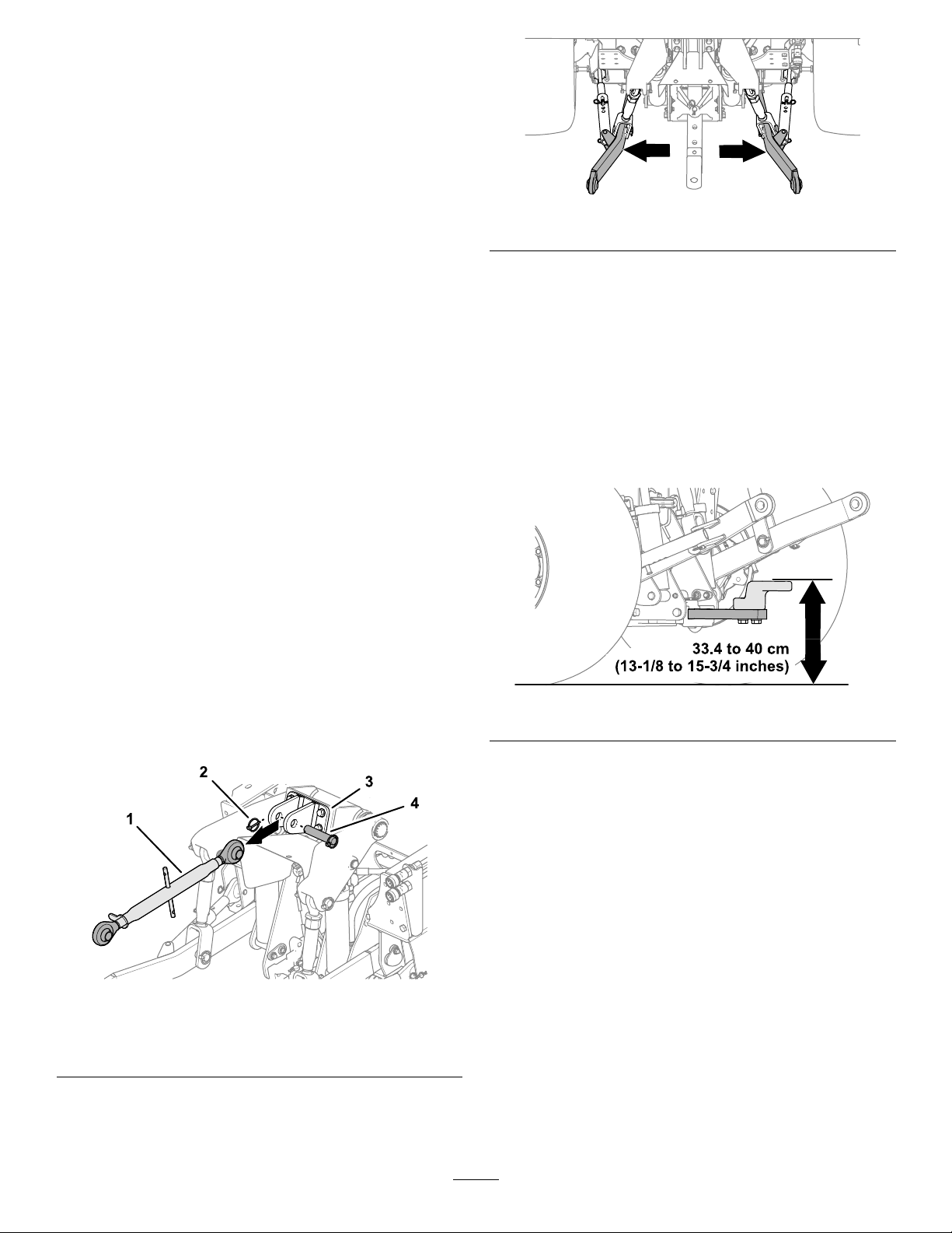
SelectingaDrawbarfortheMower
•Hitchpin-holediameter:31.75mm(1-1/4inches).
•Workingheight:33.4to40cm(13-1/8to15-3/4
inches);refertoFigure21.
theTowVehicle
PreparingtheTowVehicleand Mower
1.Ensurethatthemowerissupportedwiththe
tow-barjack;refertoSupportingtheMowerwith
theJack(page14).
2.Lowerthe3-pointhitch;refertotheOperator’s
Manualforyourtowvehicle.
3.Ifinstalled,removethelynchpin,clevispin,and
upper3-pointlinkfromtheupper-linkbracket
(Figure19).
g250512
Figure21
•Ensurethatyourdrawbardoesnotinterfereswith
thePTOdriveshaft.
ConnectingtheMowertotheTow Vehicle
1.Usejackhandletoraiseorlowerthetowbar
jackandalignthetowbartothedrawbaror
pintlehitch(Figure22).
Figure19
1.Upper3-pointlink3.Upper-linkbracket
2.Lynchpin
4.Adjustthestabilizerarms(Figure20)outward
fully;refertotheOperator’sManualsforthetow
machine.
4.Clevispin
g250419
15
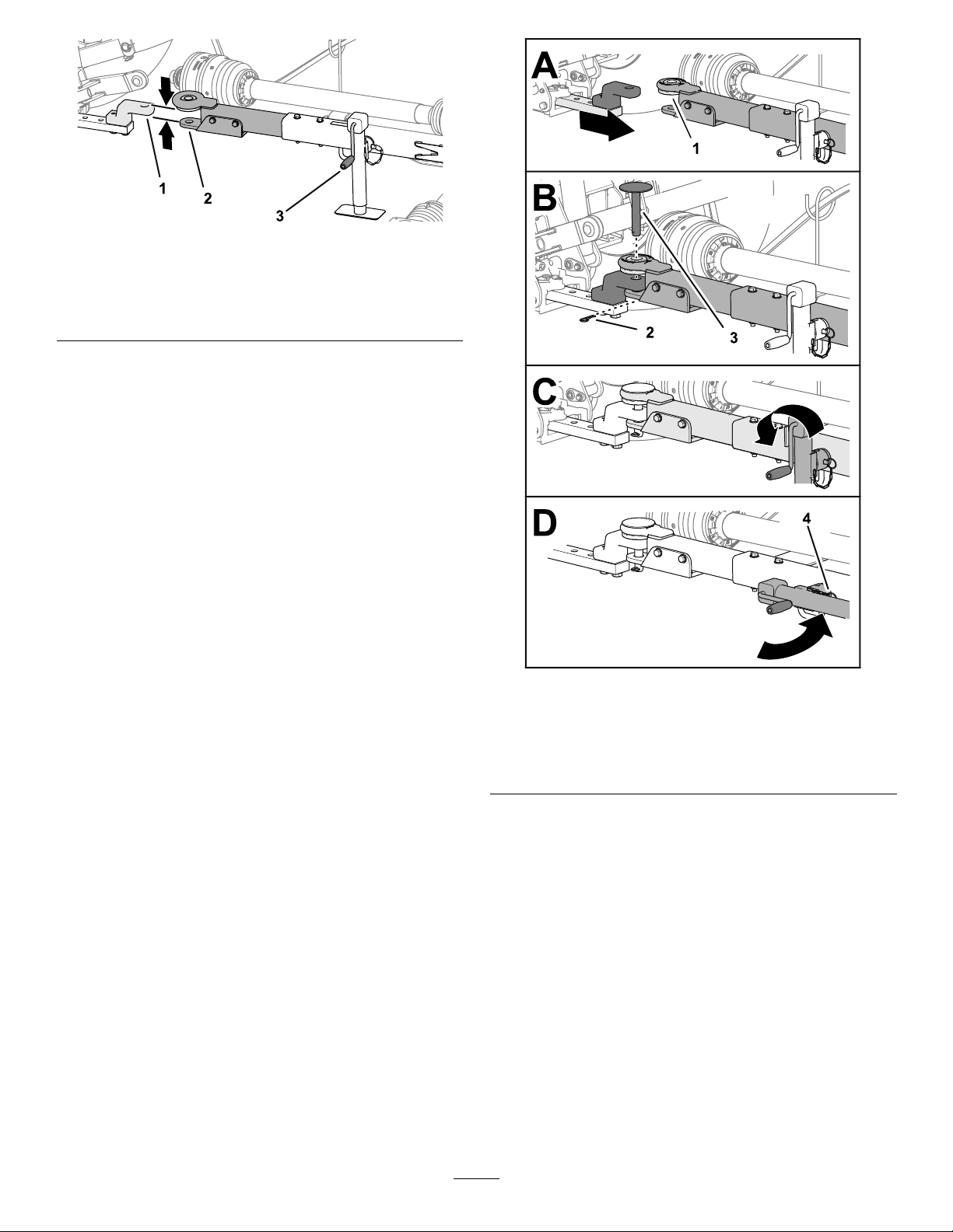
Figure22
Pintowbarshown
1.Drawbar3.Jackhandle
2.Towbar
2.Fullyraisethe3-pointhitch;refertothe
Operator’sManualforyourtowvehicle.
Note:Whenequipped,lockthe3-pointhitch.
3.Alignthedrawbarorpintlehitchofthetow
vehiclewiththetowbarofthemower(Figure
22).
4.MovetheshiftlevertotheNEUTRALposition,
engagetheparkingbrake,shutofftheengine
removethe,andwaitforallmovingpartstostop.
5.Securethetowbarasfollows:
•Ifyourmowerhasapintowbar,insertthe
hitchpinthroughtheholesinthetowbarand
drawbarandsecurethepinwiththehairpin
(Figure23).
g250416
g250418
Figure23
Pintowbarshown
1.Flangebushing3.Hitchpin
2.Hairpin4.Pin
•Ifyourtowvehiclehasapintlehitch,close
andsecurethehitch.
6.Fullyraisethejack(Figure23).
7.Removethepinthatsecuresthejacktothetow
bar,rotatethejackhorizontal,andsecurethe
hacktothetowbarwiththepin(Figure23).
16
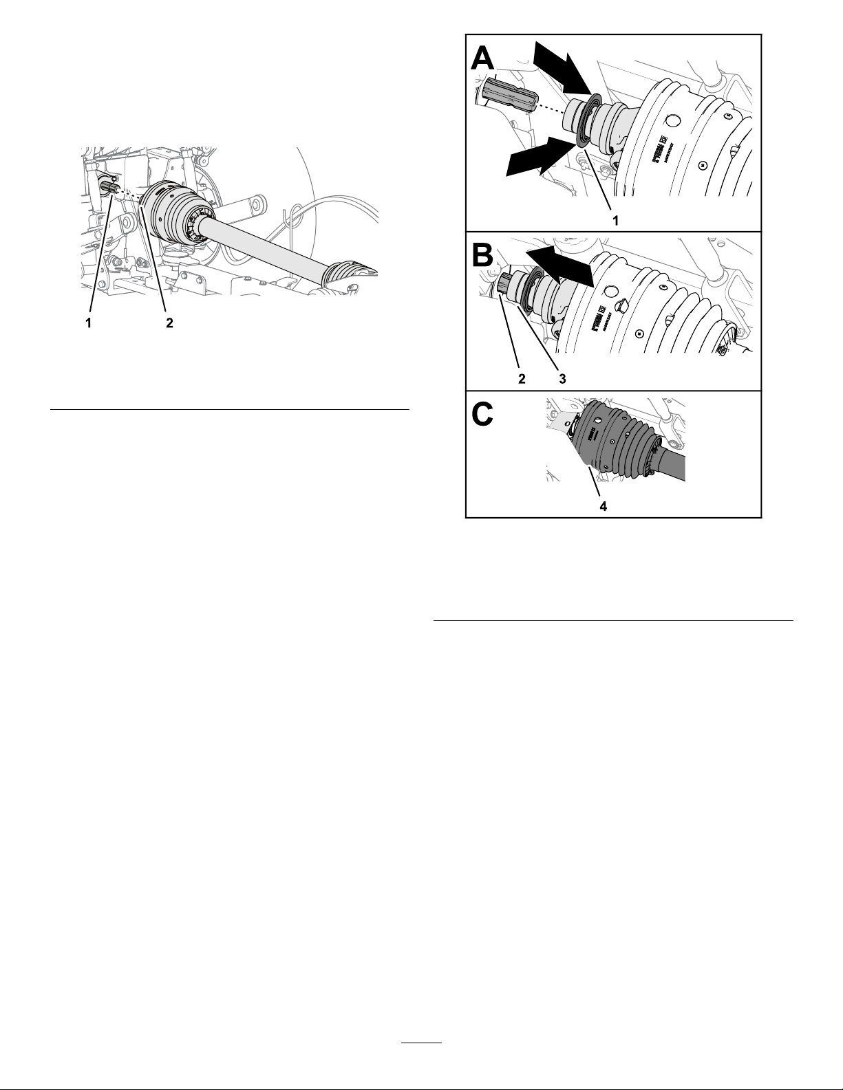
ConnectingtheDriveShafttothe PTO
1.Alignthequick-connectcouplingofthePTO
driveshaftwiththeoutputshaftofthePTO
(Figure24).
Figure24
g250417
1.PTOoutputshaft
(machine)
2.Pullbackthelockcollarofthequick-connect
coupling(Figure25).
2.Quick-connectcoupling
(PTOdriveshaft)
Figure25
1.Lockcollar(quick-connect
coupling)
2.Splines(PTOoutputshaft)4.Shield
3.Driveshaftyoke
3.Whilepullingbackthelockcollar,pullthePTO
drive-shaftyokeforwardandslipthesocketof
thecouplingoverthesplinesofthePTOoutput
shaft(Figure25).
4.Ensurethatthelockatthequick-connect
couplingsnapsintothegrooveofthePTO
outputshaftsecurely.
g250500
5.Ensurethattheshieldispositionedoverthe
driveshaftyoke(Figure25).
6.Attachtherestraintchaintoaxedpartofthe
towvehicle(Figure26).
Important:Ensurethatthereisenough
slackintherestraintchainsothatyoucan
turnthemachineinbothdirections.
17
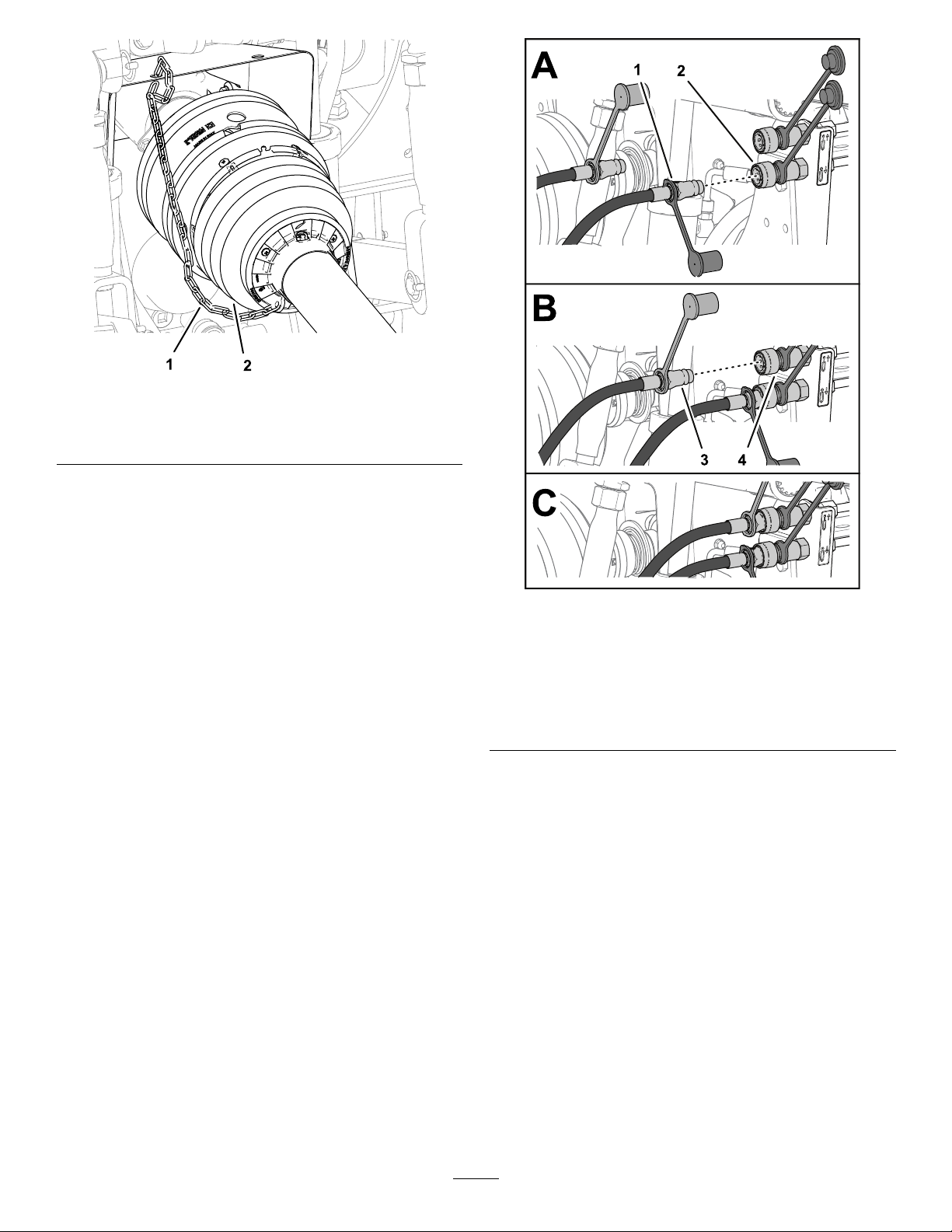
Figure26
g264215
1.PTO-shaftguard(forward
half)
2.Restraintchain
ConnectingtheHydraulicHoses
1.Identifythequick-disconnectttingsfortherear
attachment-liftandlowercircuitsforthetow
vehicle.
2.Removethedustcoversfromthe
quick-disconnectttingsofthetowvehicle.
3.Removetheblackdustcoverfromthe
quick-disconnectttingofthecylinder-extend
hoseofthemower
4.Connectthequick-connectttingcylinder
extendhosetothequick-disconnectcoupling
rear-attachment-lowercircuit(Figure27).
Figure27
1.Quick-connecttting
withblackdustcap
(cylinder-extendhose)
2.Quick-connectcoupling
(rearattachment-lower
circuit)
3.Quick-connecttting
withreddustcap
(cylinder-retracthose)
4.Quick-connectcoupling
(rearattachment-raise
circuit)
5.Removethereddustcoverfromthe
quick-disconnectttingofthecylinder-retract
hoseofthemower
6.Connectthequick-disconnectttingofthe
cylinderretracthosetothequick-disconnect
couplingrear-attachment-raisecircuit.
g250538
RoutingtheDeck-LockRopeto theMachine
1.Routethedeck-lockropefromthehoseguide
towardtheoperator’sseat(Figure28).
Important:Ensurethatyouallowslackin
theropesothatthemowercanfullyturn
rightandleftbehindthetowvehiclewithout
addingtensiontotherope,butitdoesnot
contactthePTOdriveshaft.
18

Figure28
1.Fixed-chassiscomponent3.Deck-lockrope
2.Hoseguide
2.Tietheropetothexed-chassiscomponentof
thetowvehiclesuchastheROPStube(Figure
28).
Important:Donottiethedeck-lockrope
totheseat,steeringwheel,orthehandleof
acontrol.
3.Removethechocksfromthemowertires.
•Usecarewhenapproachingblindcorners,shrubs,
trees,orotherobjectsthatmayobscureyour
vision.
•DonotrunthePTOwiththedecksraisedabove
thepartialup-stopposition.
•Stopthemowerwheneveryouarenotcutting
grass.
•Stopthemachine,engagetheparkingbrake,
shutofftheengine,removethekey ,andwaitfor
g250665
allmovingpartstostopbeforeinspectingthe
attachmentafterstrikinganobjectorifthereis
anabnormalvibrationinthemachine.Makeall
necessaryrepairsbeforeresumingoperation.
•Slowdownandusecautionwhenmakingturns
andcrossingroadsandsidewalkswiththe
machine.Alwaysyieldtheright-of-way.
•Reducespeedonroughroadsandsurfaces
•Themowerisheavy.Whenattachedtoatow
vehicle,andintheraisedposition,theweightof
themoweraffectsstability,brakingandsteering.
Exercisecautionwhentransportingbetween
workingareas.
DuringOperation
Note:Determinetheleftandrightsidesofthe
machinefromthenormaloperatingposition.
DuringOperationSafety
•Theowner/operatorcanpreventandisresponsible
foraccidentsthatmaycausepersonalinjuryor
propertydamage.
•Wearappropriateclothing,includingeye
protection;longpants;substantial,slip-resistant
footwear;andhearingprotection.Tiebacklong
hairanddonotwearlooseclothingorloose
jewelry.
•Donotoperatethemachinewhileill,tired,or
undertheinuenceofalcoholordrugs.
•Nevercarrypassengersonthemowerandkeep
bystandersandpetsawayfromthemachine
duringoperation.
•Operatethemachineonlyingoodvisibilitytoavoid
holesorhiddenhazards.
•Beforeyoustarttheengine,ensurethatalldrives
areinneutral,thePTOisdisengaged,theparking
brakeisengaged,andyouareintheoperating
position.
•Keepyourhandsandfeetawayfromrotating
parts.Keepclearofthedischargeopeningatall
times.
•Lookbehindanddownbeforebackinguptobe
sureofaclearpath.
•Neverleavearunningmachineunattended.
•Beforeleavingtheoperatingposition(including
adjustingtheheightofcut)dothefollowing:
–EnsurethatthePTOisdisengaged.
–Parkthemachineonalevelsurface.
–Engagetheparkingbrake.
–Lowerthemowerdecks.
–Shutofftheengineandremovethekey.
–Waitforallmovingpartstostopbeforeleaving
themachine.
•Donotoperatethemachinewhenthereistherisk
oflightning.
•Useaccessories,attachments,andreplacement
partsapprovedbyTheT oro®Companyonly.
•FordisassemblyorrepairofallsteelPTO
drive-shaftparts(tubes,bearings,joints,etc.),
contactyourauthorizedTorodistributor.Removal
ofcomponentsforrepairsandreassemblymay
damagesomepartsifnotperformedwithspecial
toolsbytrainedtechnicians.
•DonotoperatethemowerifthePTOordriveshaft
guardsaremissing.
•Becarefulwhenturningthemachinesothatthe
towvehicletiresdonotcontactthePTOdrive
shaft.
•Securehydraulichoses,electricalwiring,ropes,
andotheritemstokeepthemfromcontactingthe
PTOdrive-shaftguard.
19

SlopeSafety
LoweringtheMowerDecks
•Slopesareamajorfactorrelatedtolossofcontrol
androlloveraccidents,whichcanresultinsevere
injuryordeath.Y ouareresponsibleforsafeslope
operation.Operatingthemachineonanyslope
requiresextracaution.
•Reviewandunderstandtheslopeinstructionsin
themanualandonthetowvehicle.
•Evaluatethesiteconditionstodetermineifthe
slopeissafeformachineoperation,including
surveyingthesite.Alwaysusecommonsense
andgoodjudgmentwhenperformingthissurvey .
•Reviewtheslopeinstructionslistedbelowfor
operatingthemachineonslopesandtodetermine
whetheryoucanoperatethemachineinthe
conditionsonthatdayandatthatsite.Changes
intheterraincanresultinachangeinslope
operationforthemachine.
•Avoidstarting,stopping,orturningthemachineon
slopes.Avoidmakingsuddenchangesinspeedor
direction.Maketurnsslowlyandgradually.
•Donotoperateamachineunderanyconditions
wheretraction,steering,orstabilityareinquestion.
fromtheTransportPosition
1.EnsurethatthePTOisintheOFFposition;refer
totheOperator’sManualforyourtowvehicle.
2.Movethemowertoaatareathatislarge
enoughtosupportthemowerdecks.
3.Ensurethattherearenobystandersnearby .
4.Movethecontrolfortherearattachment-circuit
totheLIFTposition;refertotheOperator’s
Manualforyourtowvehicle.
Themowerdecksmayraiseslightlyand
pressureonthedecklocksreduces.
5.Pullandholdthedeck-lockrope(Figure29).
Thedecklocksrelease.
•Removeormarkobstructionssuchasditches,
holes,ruts,bumps,rocks,orotherhiddenhazards.
Tallgrasscanhideobstructions.Uneventerrain
couldoverturnthemachine.
•Beawarethatoperatingthemachineonwet
grass,acrossslopes,ordownhillmaycausethe
machinetolosetraction.Lossoftractiontothe
drivewheelsmayresultinslidingandalossof
brakingandsteering.
•Useextremecautionwhenoperatingthemachine
neardrop-offs,ditches,embankments,water
hazards,orotherhazards.Themachinecould
suddenlyrolloverifawheelgoesovertheedge
ortheedgecavesin.Establishasafetyarea
betweenthemachineandanyhazard.
•Identifyhazardsatthebaseoftheslope.If
therearehazards,mowtheslopewithapower
walk-behindmower.
•Ifpossible,keepthecuttingunit(s)loweredtothe
groundwhileoperatingonslopes.Raisingthe
cuttingunit(s)whileoperatingonslopescancause
themachinetobecomeunstable.
g250665
Figure29
1.Deck-lockrope3.Lockarm
2.Hoseguide
6.Movethecontrolfortherearattachment-circuit
totheLOWERposition;refertotheOperator’s
Manualforyourtowvehicle.
Themowerdeckslowertotheground(Figure
30).
•Useextremecautionwithotherattachments.
Thesecanchangethestabilityofthemachineand
causealossofcontrol.Alwayskeepthemachine
ingearwhengoingdownslopes.Donotcoast
downhill(applicableonlytogear-driveunits).
20
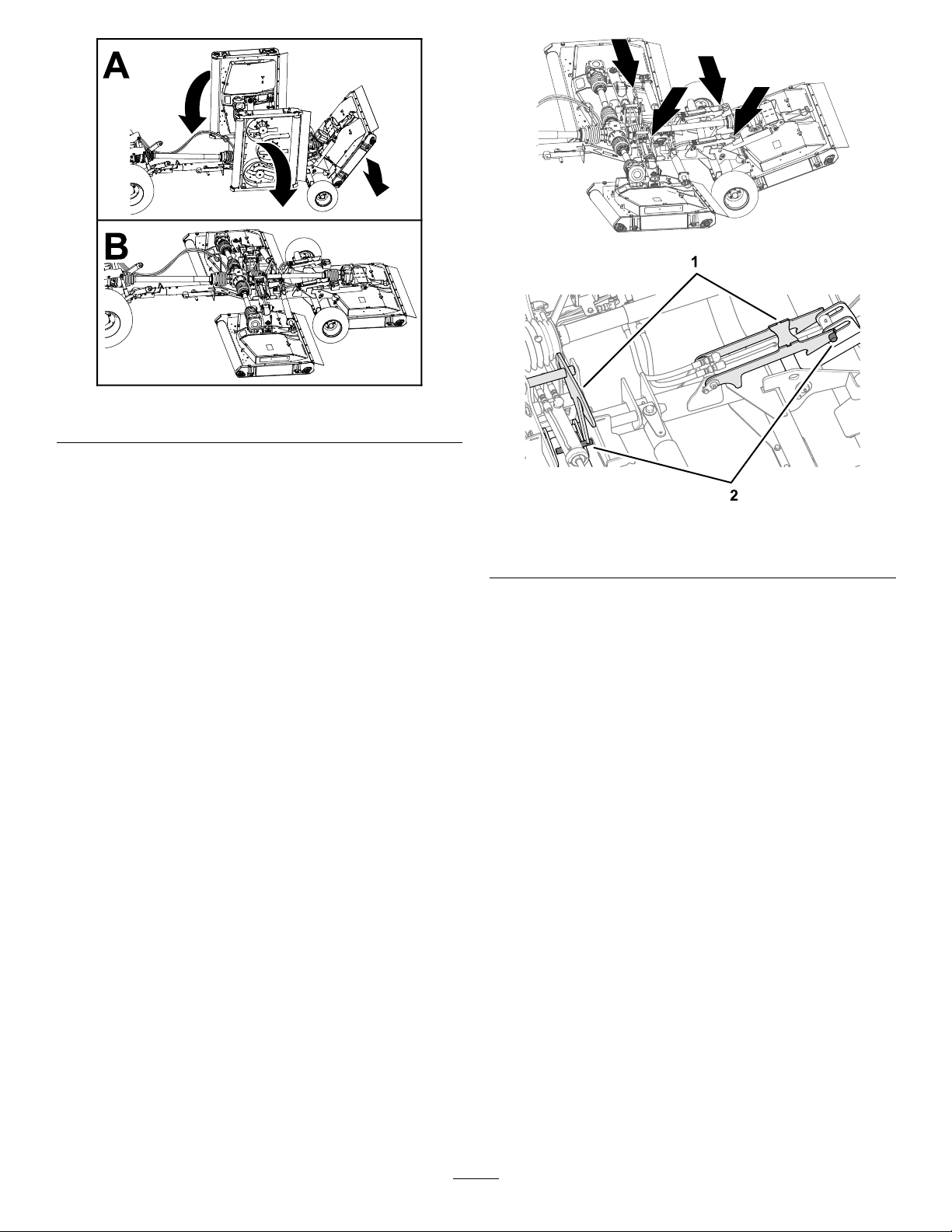
Figure30
7.Whenthedecksfullylowertotheground,
releasetheropeandattachmentcontrol.
8.Movethecontrolfortherearattachment-circuit
totheFLOATposition;refertotheOperator’s
Manualforyourtowvehicle.
g250716
g250705
g250715
Figure31
1.Decklocks2.Deckpins
RaisingtheMowerDecks whileCuttingGrass
Usethisproceduretoraisethemowerdecksslightly
whenturningthemachinesaroundattheendofa
cuttingpass.
Forinstructiononusingtherearattachmentcontrol,
refertotheOperator’sManualforyourtowvehicle.
1.Movethecontrolfortherearattachment-circuit
totheLIFTposition.
Thedecksraise,andtheliftpinscontactthe
partialup-stopportionofthedecklocks.
Note:Donotpullthedeck-lockrope.
2.Turnthetowvehicleandalignitforthenext
cuttingpass.
3.Movethecontrolfortherearattachment-circuit
totheLOWERposition.
4.EngagethePTO.
RaisingtheMowerDecks totheTransportPosition
ForinstructiononusingthePTOandrearattachment
control,refertotheOperator’sManualforyourtow
vehicle.
1.Movethemowertoaatarea.
2.ShutoffthePTO.
3.Pullandholdthedeck-lockrope(Figure32).
21
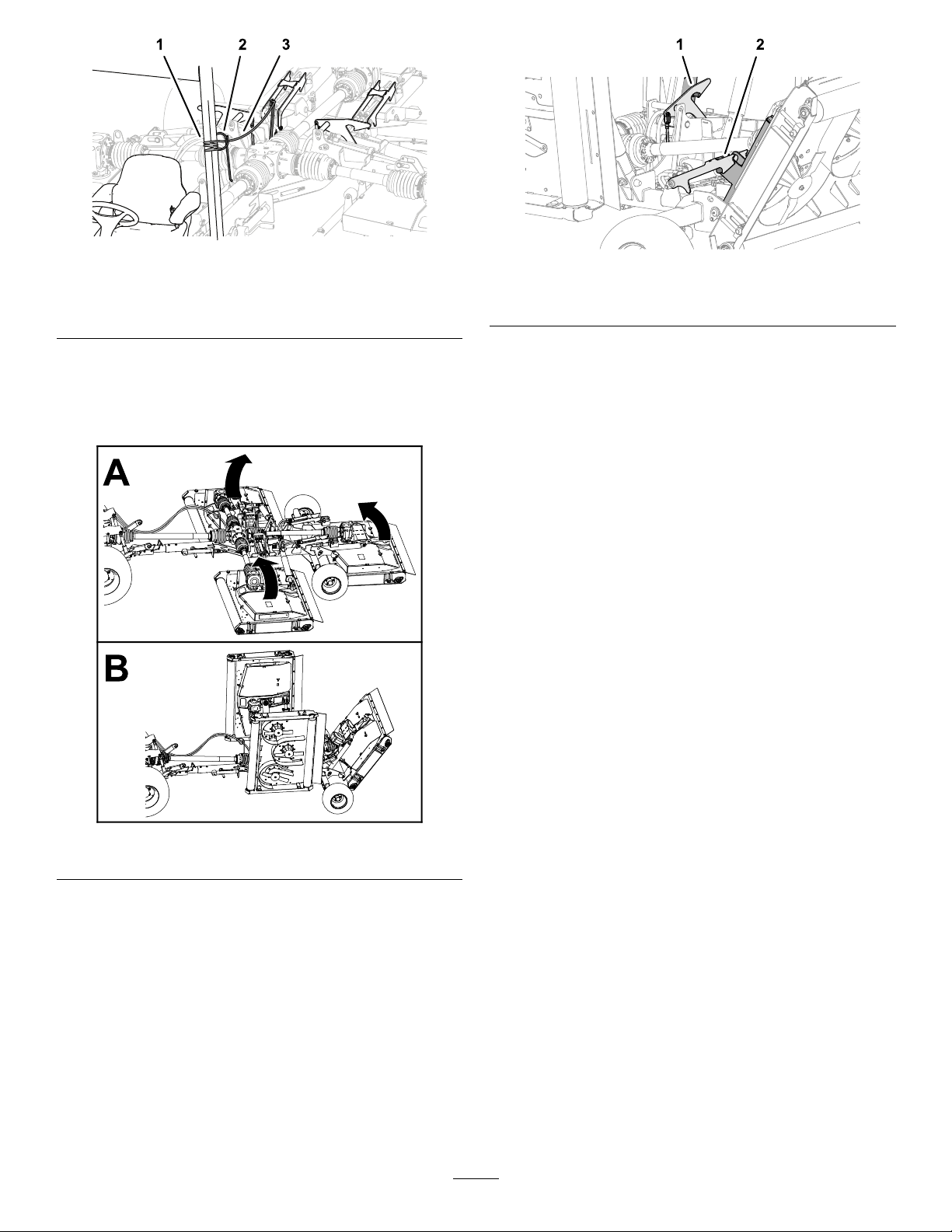
Figure32
1.Deck-lockrope3.Lockarm
2.Hoseguide
g250665
Figure34
1.Rightdecklock
2.Centerdecklock
g250714
4.Movethecontrolfortherearattachment-circuit
totheRAISEposition.
ThemowerdecksraisetotheTRANSPORT
position(Figure33).
6.Movethecontrolfortherearattachment-circuit
totheLOWERpositionuntilthedecklocks
supporttheweightofthedecks.
AdjustingtheHeight-of-Cut
1.Ifthemowerisinstalledtothetowvehicle,
performthefollowing:
A.EnsurethatthePTOisdisengaged.
B.Ifthemowerdecksareinthetransport
position,lowerthedecks;refertoLowering
theMowerDecksfromtheTransport
Position(page20).
C.Engagetheparkingbrake,shutoffthe
engine,removethekey ,andwaitforall
movingpartstostop.
2.Determinetheheightthatyouwanttocutthe
grass.
3.Loosenthe4locknutsthatsecurethe4
height-of-cutadjusters(Figure35)ofthemower
deck.
Figure33
5.Whenthedecksfullyraised,releasetherope
andattachmentcontrol.
Thedecklocksengagethedeckpins(Figure
34).
g250706
22
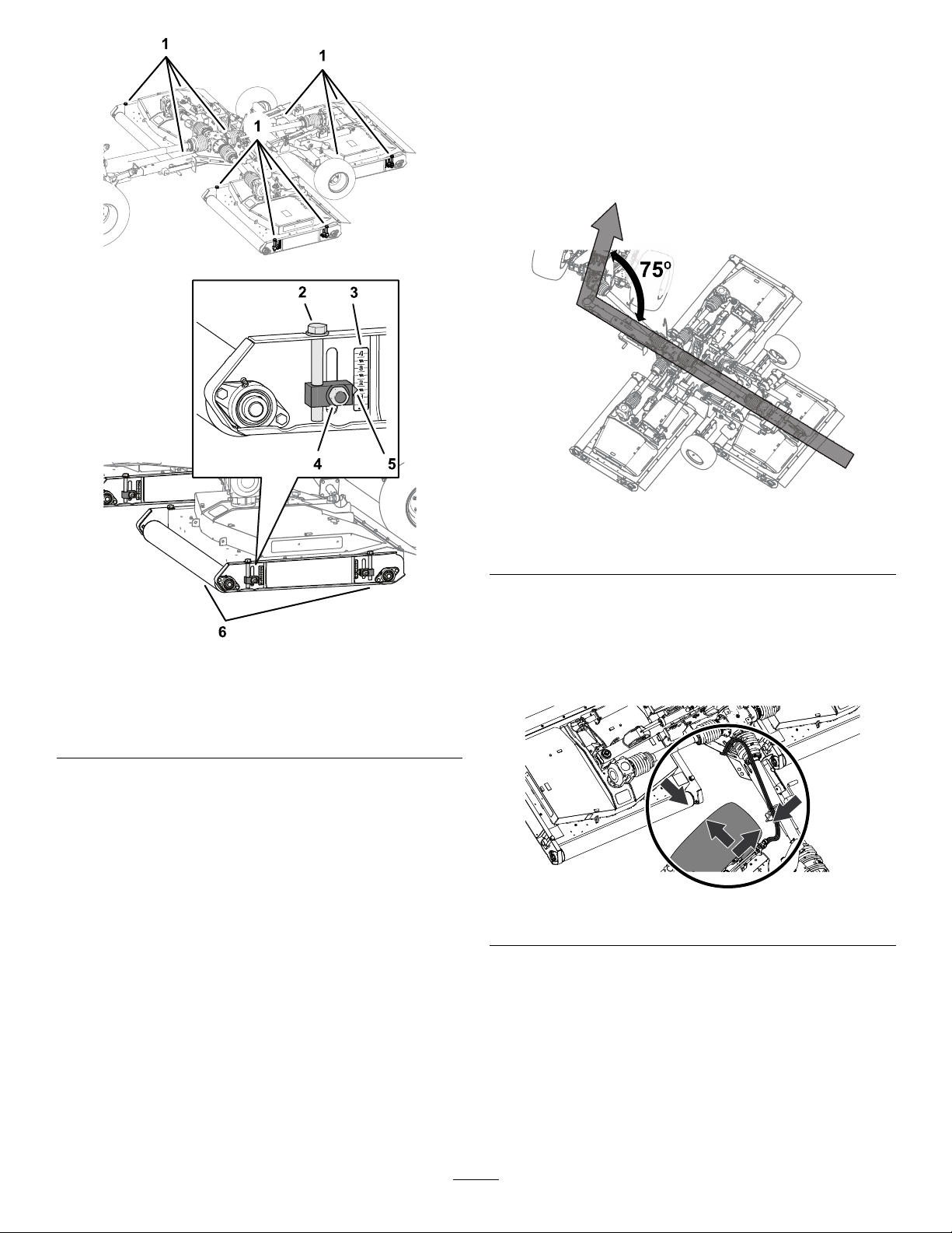
MakingaSharpTurn
1.ShiftthetowvehicletoLOWGEARorLOWRANGE.
2.Drivingthemachineslowly,steertomakethe
sharpturn.
Important:Donotexceedthe75°maximum
towvehicletomowerangle.
g250931
g264251
Figure36
75°MaximumT owVehicletoMowerAngle
Figure35
1.Height-of-cutadjusters
2.Adjustercapscrew
3.Cut-heightscale
4.Locknut
5.Pointer
6.Rollers
4.Workingat1ofthedeckrollers,turntheadjuster
capscrewtoraiseorlowerthemoweruntilthe
pointeralignswiththegrasscutheightthatyou
determinedinstep2.
5.Tightenthelocknutsfor2height-of-cutadjusters.
6.Repeatsteps4and5fortheheight-of-cut
adjustersattheotherroller.
7.Repeatsteps3through6fortheotherdecks.
3.Asyouturn,checktoensureclearancebetween
thetireofthetowvehicleandthepartsofthe
g250930
mower(Figure37).
Note:Ifthetireistooclosetothemower,turn
moregradually.
g264252
Figure37
23
AfterOperation
AfterOperationSafety
•Parkthemachineonalevelsurface;engagethe
parkingbrake;shutofftheengine;removethekey;
andwaitforallmovementtostopbeforeleaving
themachine.
TransportingtheMachine
Important:Raiseandlatchthedecksbefore
loadingthemowerontoorofffromthetrailer.
•Usecarewhenloadingorunloadingthemachine
intoatraileroratruck.
•Usefull-widthrampsforloadingthemachineinto
atraileroratruck.
•Donotstepon,overorunderthedriveshaft.
•DonotusetherestrainchainofthePTO-shaft
guardtosupporttheshaftwhentransportingor
storingthemower.
•DonotrestthePTOshaftontheground.
•DonotallowthePTO-shaftguardstopullapart.
•Keepallpartsofthemachineingoodworking
conditionandallhardwaretightened.
•Replaceallworn,damaged,ormissingdecals.
CleanandInspect
ServiceInterval:Aftereachuse
Raisethemowerdecksandthoroughlywashthem.
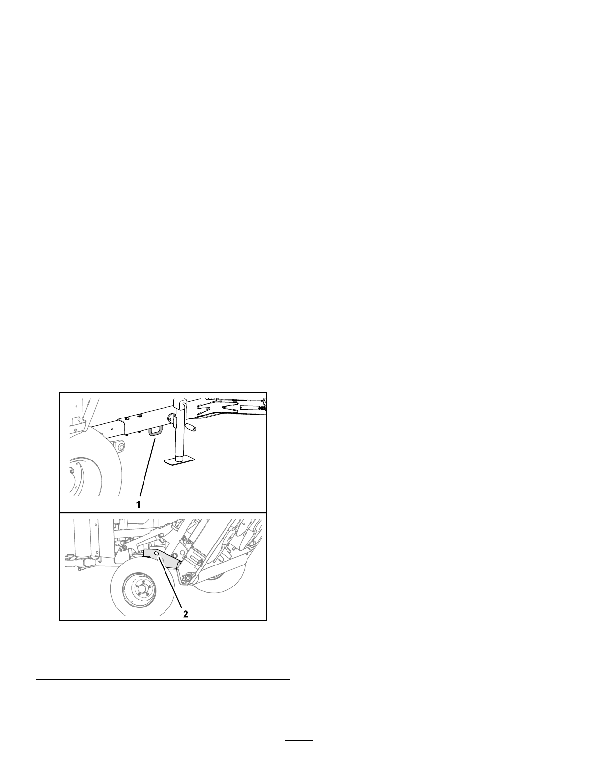
Tie-DownPoints
RefertoOperator’sManualforyourtowchassisand
towvehiclethetie-downlocationsofthemachine.
1.Drivethetowvehicleuptheramp.
2.Shutofftheengine,removethekey,andengage
theparkingbrake.
3.Lowerthejack.
4.Tiedownthemachinenearthewheelswith
straps,chains,orcables.
Note:Refertolocalregulationsfortie-down
requirements.
5.Secureblocksatthewheelsofthemachineto
thebedofthetrailerortruck.
6.EnsurethatthePTOdriveshaftiscoupledto
atowvehicleorsecuredtothetowbarofthe
mower.
Figure38
1.Forwardtie-downpoint2.Forwardtie-downpoint
(leftandrightsides)
g264216
24

Maintenance
CAUTION
Ifyouleavethekeyintheswitch,someonecouldaccidentlystarttheengineandseriously
injureyouorotherbystanders.
Removethekeyfromtheswitchbeforeyouperformanymaintenance.
WARNING
Ifthemowerdecksareraisedbutnotlatched,thedeckscouldlowerunexpectedlyand
seriouslyinjureyouorotherbystanders.
Fullyraisealldecksandensurethepinsonallliftarmsengagethelatches.
RecommendedMaintenanceSchedule(s)
MaintenanceService
Interval
Aftertherst50hours
Beforeeachuseordaily
Aftereachuse
Every50hours
Every500hours
Beforestorage
MaintenanceProcedure
•Changethecentergearlubricant.
•Changethecentergearlubricant.
•Checkthemowerbelts.
•Checkthetireairpressure.
•CheckthePTOanddriveshaftguards.
•GreasetheconstantvelocityjointforthePTOdriveshaft.
•Checkthemowerblades.
•Cleanandinspectthemower.
•Greasethetelescopingdrive-shaftjoints.
•GreasethedriveshaftU-joints.
•Greasethedriveshaftguard-slipjoints.
•Greasetheliftarms,hydrauliccylinders,latches,andimpactstruts(also,lubricate
themowerimmediatelyaftereverywashing).
•Greasethespindles.
•Greasethebelttensioner.
•Greasethedeckrollers(also,lubricatetherollersimmediatelyaftereverywashing).
•Checkthegearboxuidlevel.
•Inspectgearboxandspindlebearings.
•Performall50-hourmaintenanceprocedures.
•Removealldebris.
•Inspecttherollerbearings.
•Paintanychippedsurfaces.
•Changethecentergearlubricant.
Yearly
•Changethecentergearlubricant.
•InspectthePTO-shaftsplinesforsignsofwear.
25

LiftingtheMower
1.Liftthemowerattheaxlehalvesasshownin
Figure39.
Figure39
1.Axlehalves
2.Usejackstandstosupportthemower.
AccessingtheMower Decks
RemovingtheDeckCovers
g264176
1.Releasethe3latchesthatsecurethecoverof
themowerdeck(Figure40).
Figure40
1.Knob(deck
cover—non-CEmowers)
2.Latch(mower-deckcover)4.Knob(non-CEmowers)or
2.Loosentheknoborbolt(CEmowerdeck)that
securesthecoverofthemowerdecktothe
mowerdeck(Figure40).
3.Liftandremovethecoverfromthedeck.
4.Repeatsteps1and2fortheothercover(Figure
40).
3.Bolt(deckcover—CE
mowers)
bolt(CEmowers)
g251061
26

InstallingtheDeckCovers
1.Alignthelatchesofthemower-deckcoverwith
theholesinthemowerdeck(Figure41).
Lubrication
GreaseSpecication
No.2lithiumbasegrease
GreasingthePTOShaftConstant VelocityJoint
ServiceInterval:Beforeeachuseordaily
Applythespeciedgreasetothe3greasettingsat
theforwardendofthePTOdriveshaft(Figure42).
Figure41
1.Latch(mower-deckcover)3.Knob(deck
2.Knob(non-CEmowers)or
bolt(CEmowers)
cover—non-CEmowers)
4.Bolt(deckcover—CE
mowers)
2.Assemblethedeckcovertothemowerdeck
(Figure41).
3.Securethecover(Figure41)asfollows:
•Non-CEmowers:threadtheknobthrough
thecoverandintothemowerdeck,and
tightentheknob.
•CEmowers:threadtheboltintothemower
deck,andtightenthebolt.
4.Securethe3latchesofthecovertothemower
deck(Figure41).
g255325
g254821
g255326
Figure42
5.Repeatsteps1through4fortheothercovers
thatyouremoved(Figure41).
27

GreasingtheTelescoping Drive-ShaftJoints
ServiceInterval:Every50hours
1.PartiallyextendthePTOdriveshafttoaccess
thegreasettingnearthemiddleoftheinboard
drive-shaftguard(Figure43).
g255328
g264299
Figure43
2.Applygreasetothe4greasettingsforthe
telescopingdrive-shaftjointsasshowninFigure
43.
GreasingtheDriveshaftU-Joints
ServiceInterval:Every50hours
Applythespeciedgreasetothe7ttingforthedrive
shaftU-jointsasshowninFigure44.
g264298
Figure44
g255327
28

GreasingtheDriveShaft Guard-SlipJoints
ServiceInterval:Every50hours
Applythespeciedgreasetothe6greasettingsfor
thedriveshaftguard-slipjointsasshowninFigure45.
g264214
g251060
Figure46
LeftorRightMowerDeck
1.Outboard
•Applygreasetheliftarmsandhydrauliccylinders,
andimpactstrutsofthecentermowerdeck(Figure
47).
Figure45
GreasingtheLiftArms,Hydraulic Cylinders,Latches,andImpact Struts
ServiceInterval:Every50hours(also,lubricate
themowerimmediatelyafterevery
washing).
•Applythespeciedgreasetotheliftarms,
hydrauliccylinders,andimpactstrutsoftheleft
andrightmowerdecks(Figure46).
g251059
Figure47
CenterMowerDeck
g264213
1.Backofthemower
GreasingtheSpindles
ServiceInterval:Every50hours
Applythespeciedgreasetothegreasettingatthe
3spindlesateachmowerdeck(Figure47).
g251062
Figure48
Leftdeckshown.Rightandcenterdecksaresimilar.
29

GreasingtheBeltTensioners
ServiceInterval:Every50hours
Applythespeciedgreasetothegreasettingsatthe
2belttensionersofeachmowerdeck.
2.Greasethedeckrollerbearingsattherightside
ofthedeck(Figure50).
3.Repeatsteps1and2forthedeckrollersatthe
otherdecks.
ServicingtheGearboxes
Customersuppliedmaterial:PTFEthreadsealant
andasmallhandpump.
GearboxFluidSpecication
•ToroPremiumTractoruid
•Mobiluid™424tractorhydraulicuid
CheckingtheGearboxFluidLevel
Figure49
GreasingtheDeckRollers
ServiceInterval:Every50hours(also,lubricate
therollersimmediatelyafterevery
washing).
1.Applythespeciedgreasethedeckroller
bearingsattheleftsideofthedeck(Figure50).
g264169
ServiceInterval:Every50hours
1.Removethedipstickfromthedipstickportatthe
topofthecentergearbox(Figure51orFigure
52).
1.Leftsideofthemachine
g255251
Figure51
CenterGearbox
1.Dipstick3.Fulldipstickmark
2.Dipstickport4.Adddipstickmark
g254862
Figure50
30

Figure52
DeckGearbox
1.Dipstick3.Fulldipstickmark
2.Dipstickport4.Adddipstickmark
ChangingtheCenterGearBox Lubricant
ServiceInterval:Aftertherst50hours
Yearly
DrainingtheCenterGearbox
g255263
g255203
Figure53
CenterGearboxDrainLocation
2.Checktheuidlevelindicatedonthedipstick
(Figure51orFigure52).
Theuidlevelshouldindicatebetweenthefull
andaddmarksofthedipstick.
Note:Addlubricantasneededtoraisethe
levelbetweenthefullandaddmarks;referto
FillingtheCenterGearbox(page32)orFilling
theDeckGearbox(page32).
3.Cleanthethreadsofthedipstickandllplugand
applyPTFEthreadsealanttothethreads.
4.Threadthedipstickintothellportandtighten
thedipstick(Figure51orFigure52).
5.Repeatsteps1through4forthedeck
gearboxes.
1.Workingthroughtheaccessholeatthe
bottom-frameplateofthemower,alignadrain
panunderthehole(Figure54).
Figure54
1.Socket-drainplug
2.Drainport(center
grearbox)
3.Accesshole
(bottom-frame
plate—mower)
g255204
2.Removethesocket-drainplugfromthedrain
portofthecentergearboxandallowthelubricant
todraincompletely(Figure54).
3.Cleanthethreadsofthedrainplugandapply
PTFEthreadsealanttothethreads.
4.Assemblethedrainplugintothedrainportand
tightentheplug.
31

FillingtheCenterGearbox
ChangingtheDeckGearbox
Centergearboxuidcapacity:1,774mL(60oz)
1.Removethedipstickfromthedipstickportatthe
topofthecentergearboxandwipecleanthe
dipstick(Figure55).
Lubricant
ServiceInterval:Aftertherst50hours
Yearly
EmptyingtheDeckGearbox
1.Removethedipstickfromthetopofthegearbox
(Figure56).
Figure55
CenterGearbox
1.Dipstick4.Fillport
2.Fillplug5.Fulldipstickmark
3.Dipstickport6.Adddipstickmark
2.Removethellplugfromthellportatthetopof
thegearbox(Figure55).
3.Add1,774mL(60oz)ofthespeciedgear
lubricanttothegearboxthroughthellport
(Figure55).
4.Threadthedipstickintotheport,removethe
dipstick,andcheckthatthelubricantlevel
(Figure55).
Theuidlevelshouldindicatebetweenthefull
andaddmarksofthedipstick.
Note:Addlubricantasneededtoraisethelevel
betweenthefullandaddmarks.
5.Cleanthethreadsofthedipstickandllplugand
applyPTFEthreadsealanttothethreads.
g255252
g255295
Figure56
1.Dipstick2.Dipstickport
2.Throughthedipstickport,useasuctionpumpto
removetheuidfromthegearbox(Figure56).
3.Repeatsteps1and2fortheotherdeck
gearboxes.
FillingtheDeckGearbox
Deckgearboxuidcapacity:1,064mL(36oz)
1.Add1,064mL(36oz)ofthespeciedgear
lubricanttothegearboxthroughthedipstickport
(Figure57).
6.Threadthedipstickintothellportandtighten
thedipstick(Figure55).
7.Assemblethellplugintothellportandtighten
theplug(Figure55).
32
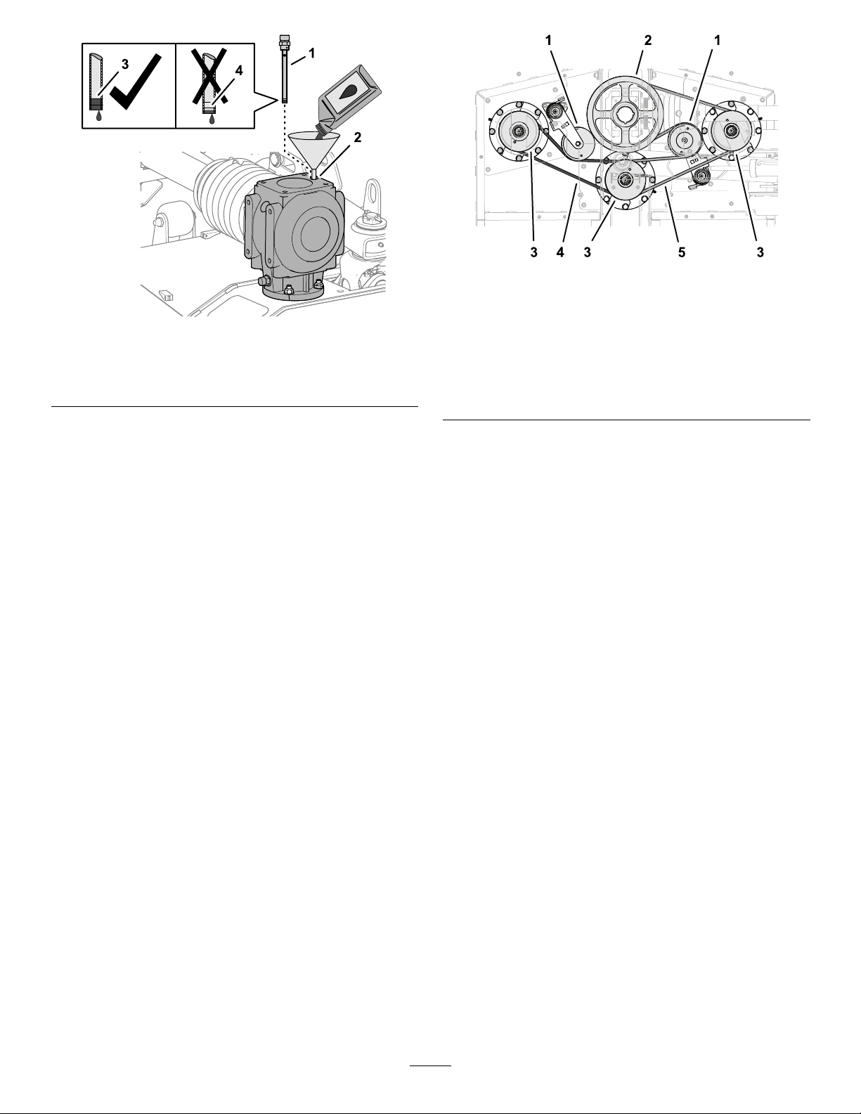
Figure57
1.Dipstick3.Fulldipstickmark
2.Dipstickport4.Adddipstickmark
g251058
Figure58
Thebeltsfortheleftdeckareshown.Thebeltsrightand
g255294
1.Tensionerpulleys
2.Drivepulleys
3.Spindlepulleys(left,
center,andright)
centerdecksaresimilar.
4.Shortbelt(left)
5.Longbelt(right)
2.Threadthedipstickintotheport,removethe
dipstick,andcheckthatthelubricantlevel
(Figure57).
Theuidlevelshouldindicatebetweenthefull
andaddmarksofthedipstick.
Note:Addlubricantasneededtoraisethelevel
betweenthefullandaddmarks.
3.Cleanthethreadsofthedipstickandapply
PTFEthreadsealanttothethreads.
4.Threadthedipstickintothellportandtighten
thedipstick(Figure57).
5.Repeatstepsand1through4fortheotherdeck
gearboxes.
CheckingtheMowerBelts
ServiceInterval:Aftertherst50hours
Thebladedrivebelts,tensionedbythespringloaded
idlerpulleys,aredurable.However,aftermanyhours
ofuse,thebeltswillshowsignsofwear.Signsofa
wornbeltinclude:squealingwhenbeltisrotating,the
mowerbladesslipwhencuttinggrass,thebelthas
frayededges,thebelthasburnmarksandcracks,
andpoorqualityofcut.Replacethebeltsifyounotice
anyoftheseconditions.
1.Removethedeckcovers;refertoRemovingthe
DeckCovers(page26).
2.Checktheshortandlongbeltforsignsof
damageorexcessivewear.
Replacedamagedorwornbelts;referto
ReplacingtheMowerBelts(page33).
3.Installthedeckcovers;refertoInstallingthe
DeckCovers(page27).
ReplacingtheMowerBelts
Note:Youmustremovethelongbelttoreplacethe
shortbelt.
RemovingtheLongBelt
1.Removethebeltcovers;refertoRemovingthe
DeckCovers(page26)
2.Useabreakerbarorsimilartooltorotatethebelt
tensionerforthelongbeltcounterclockwiseand
slipthebeltoffthetensionerpulley(Figure59).
33
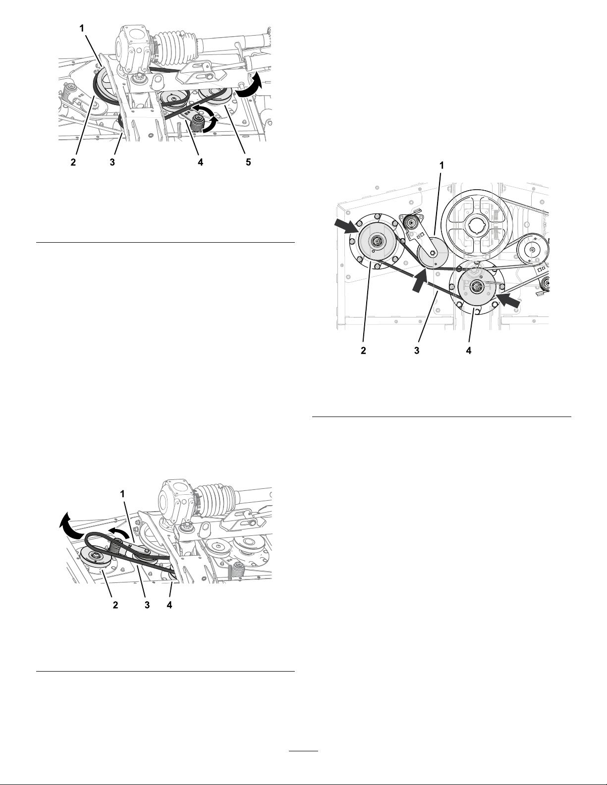
Figure59
1.Drivepulley4.Tensionerandpulley
2.Longbelt5.Right-spindlepulley
3.Center-spindlepulley
3.Slipthelongbeltoffthedrivepulley,
center-spindlepulley,andright-spindlepulley
(Figure59).
4.Removethebeltfromthemower.
Note:Youmayneedtorotatethebeltwhile
removingitfromthecenter-spindlepulley.
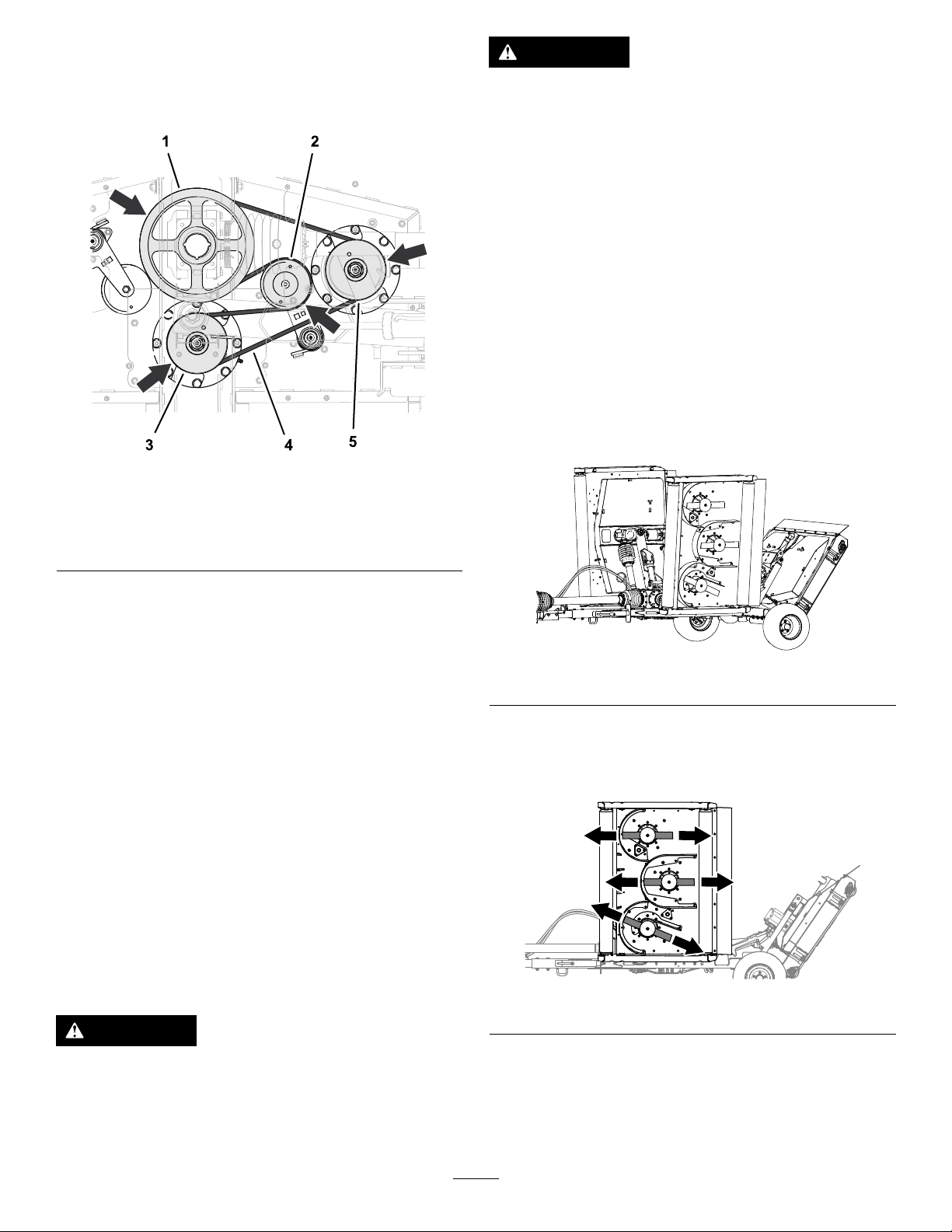
InstallingtheShortBelt
1.Installthelongbelt;refertoInstallingtheLong
Belt(page35).
2.Routethelongbeltaroundtheleft-spindlepulley
andthelowergrooveofthecenter-spindlepulley
(Figure61).
g255022
Note:Youmayneedtorotatethebeltwhile
removingitfromthecenter-spindlepulley.
RemovingtheShortBelt
1.Removethebeltcovers;refertoRemovingthe
DeckCovers(page26).
2.Ifinstalled,removethelongbelt;referto
RemovingtheLongBelt(page33).
3.Useabreakerbarorsimilartooltorotatethebelt
tensionerfortheshortbeltcounterclockwiseand
slipthebeltoffthetensionerpulley(Figure60).
Figure61
1.Tensionerandpulley
2.Left-spindlepulley4.Center-spindlepulley
3.Shortbelt
3.Useabreakerbarorsimilartooltorotatethe
belttensionercounterclockwiseandslipthebelt
overthetensionerpulley(Figure61).
g255021
Figure60
1.Tensionerandpulley
2.Left-spindlepulley4.Center-spindlepulley
3.Shortbelt
4.Slipthelongbeltoffthedrivepulley,
center-spindlepulley,andright-spindlepulley
5.Removethebeltfromthemower.
g255020
34
InstallingtheLongBelt
1.Routethelongbeltaroundthedrivepulley,
uppergrooveofthecenter-spindlepulley,and
right-spindlepulley(Figure62).
Figure62
1.Drivepulley4.Longbelt
2.Tensionerandpulley5.Right-spindlepulley
3.Center-spindlepulley
DANGER
Awornordamagedbladecanbreak,anda
pieceofthebladecouldbethrowntowardyou
orabystander,resultinginseriouspersonal
injuryordeath.
•Inspectthebladeperiodicallyforwearor
damage.
•Replaceawornordamagedblade.
PreparingtoServicetheMower Blades
Note:Y ouneedthemowerinstalledtothetow
vehiclewhenservicingthemowerblades.
1.DisengagethePTO,movethemachinetoa
levelsurface,andengagetheparkingbrake.
2.Raiseandlatchthemowerdecks,shutoffthe
g255023
engine,andremovethekey(Figure63).
2.Useabreakerbarorsimilartooltorotatethe
belttensionercounterclockwiseandslipthebelt
overthetensionerpulley(Figure62).
3.Ifyouareonlyreplacingthelongbelt,installthe
deckcovers;refertoInstallingtheDeckCovers
(page27).
4.Installthedeckcovers;refertoInstallingthe
DeckCovers(page27).
ServicingtheBlades
Maintainsharpbladesthroughoutthecuttingseason
becausesharpbladescutcleanlywithouttearingor
shreddingthegrassblades.Tearingandshredding
turnsgrassbrownattheedges,whichslowsgrowth
andincreasesthechanceofdisease.
Checkthebladesdailyforsharpness,andforany
wearordamage.Sharpenthebladesasnecessary.
Ifabladeisdamagedorworn,replaceitimmediately
withagenuineTororeplacementblade.
DANGER
Themowerbladesaresharpandcaninjure
you.
Wearheavyleatherorcutresistantgloves
whenservicingwiththeblades.
g255457
Figure63
CheckingforBentMowerBlades
1.AlignthemowerbladeasshowninFigure64.
g256136
Figure64
2.Cleanthebottomofthemowerdeckatthearea
adjacenttothecuttingedgeattherearofthe
blade(Figure65).
35
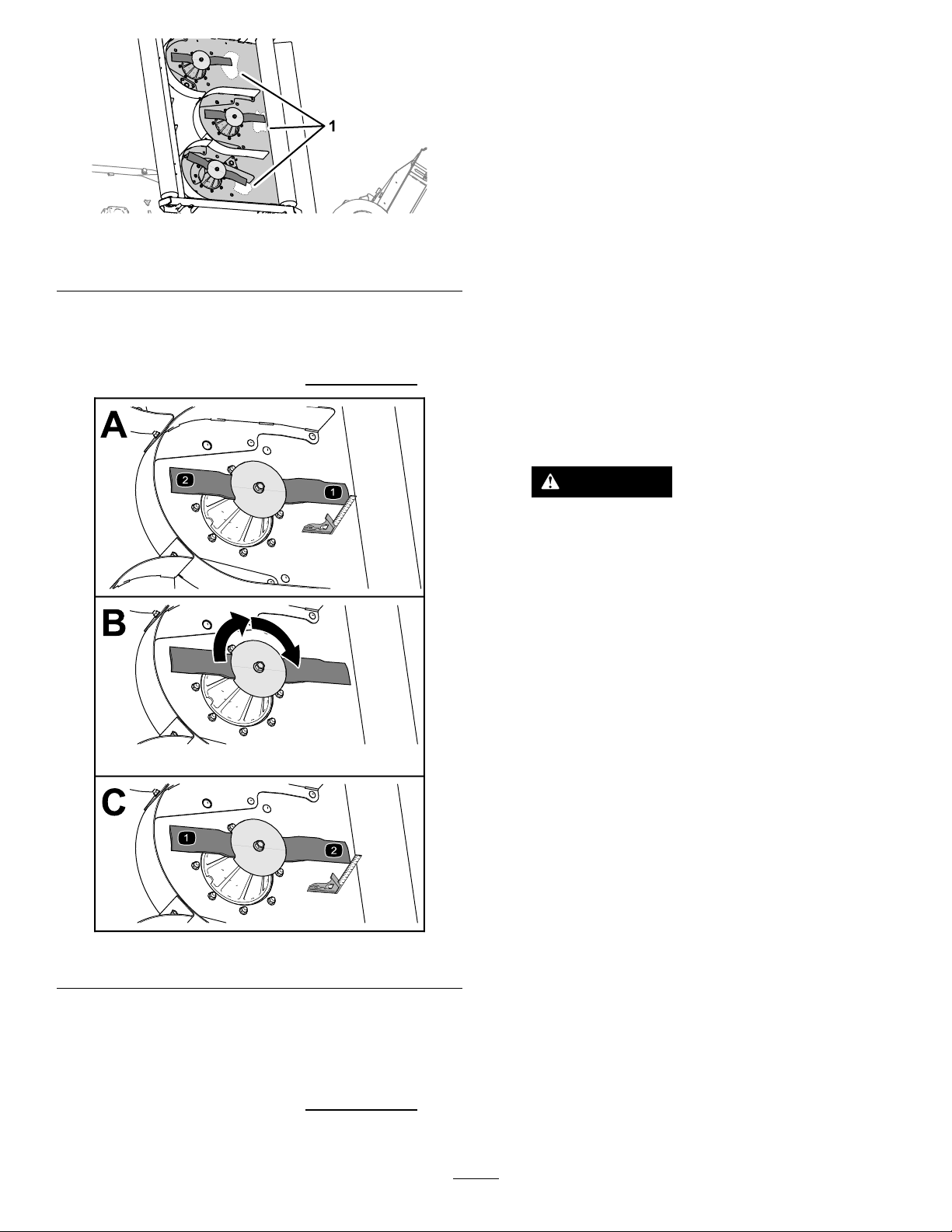
Figure65
1.Cleanarea(bottomofthemowerdeck)
Thedifferencebetweenmeasurementsthatyou
observedinsteps4and6exceed3mm(1/8
inch),thebladeisbent,andyoumustreplace
theit;refertoRemovingtheBlades(page37)
andInstallingtheBlades(page38)
6.Repeatsteps3through5fortheotherblades
ofthemowerdeckorsteps1through6forthe
otherdecks.
g255531
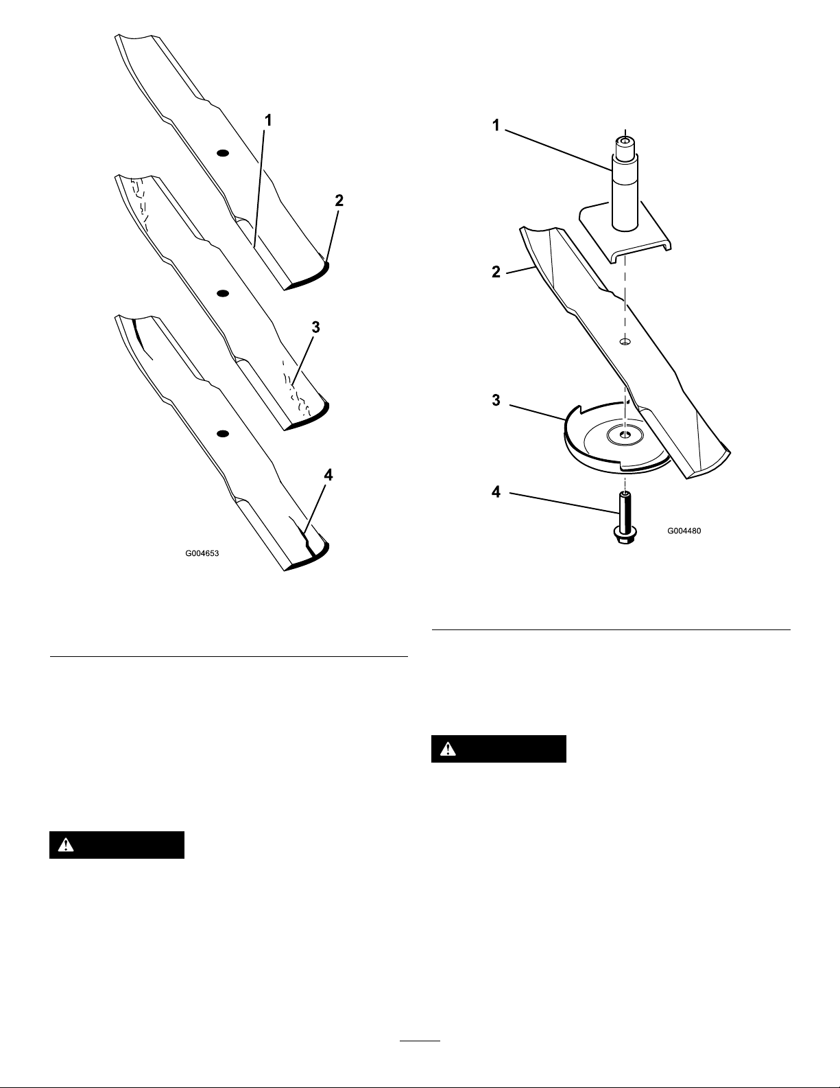
InspectingtheBlades
ServiceInterval:Beforeeachuseordaily
3.Useacombinationsquaretomeasurethe
distancebetweenthecleanareaofthedeckand
thetipofthecuttingedge(Figure66).
Recordyourmeasurement.
1.Inspectthecuttingedges(Figure67).Ifthe
edgesarenotsharporhavenicks,removeand
sharpentheblades.RefertoSharpeningthe
Blades(page37).
2.Inspecttheblades,especiallythesailarea
(Figure67).Ifyounoticeanydamage,wear,ora
slotforminginthisarea(Figure67),immediately
installanewblade.
DANGER
Ifyouallowthebladetowear,aslotwill
formbetweenthesailandatpartofthe
blade.Eventuallyapieceoftheblade
maybreakoffandbethrownfromunder
thehousing,possiblyresultinginserious
injuryordeathtoyouorbystanders.
•Inspectthebladeperiodicallyforwear
ordamage.
•Nevertrytostraightenabladethat
isbentorweldabrokenorcracked
blade.
Figure66
4.Rotatetheblade180°(Figure66).
5.Measurethedistancebetweenthecleanarea
onthedeckandthetipofthecuttingedge
(Figure66).
Recordyourmeasurement
•Replaceawornordamagedblade.
g255530
.
36
2.Rotatethebladeboltclockwisetoremovethe
bolt(Figure68).
Important:Thebladeboltshaveleft-hand
threads
Figure67
1.Cuttingedge3.Wear/slotforming
2.Sailarea4.Crack
RemovingtheBlades
Bladesmustbereplacedifasolidobjectishit,ifthe
bladeisoutofbalanceorisbent.T oensureoptimum
performanceandcontinuedsafetyconformanceof
themachine,usegenuineTororeplacementblades.
Replacementbladesmadebyothermanufacturers
mayresultinnon-conformancewithsafetystandards.
WARNING
Contactwithasharpbladecancauseserious
injury.
Wearglovesorwrapsharpedgesoftheblade
witharag.
1.Holdthebladeendusingaragorthickly-padded
glove.
g004480
g004653
1.Spindle
2.Sailareaofblade
Figure68
3.Anti-scalpplate
4.Bladebolt
3.Removetheanti-scalpplateandbladefromthe
spindleshaft(Figure68).
SharpeningtheBlades
WARNING
Whensharpeningblade,piecesofbladecould
bethrownandcauseseriousinjury.
Wearpropereyeprotectionwhensharpening
blades.
1.Sharpenthecuttingedgeatbothendsofthe
blade(Figure69).
Note:Maintaintheoriginalangle.Theblade
retainsitsbalanceifthesameamountof
materialisremovedfrombothcuttingedges.
37
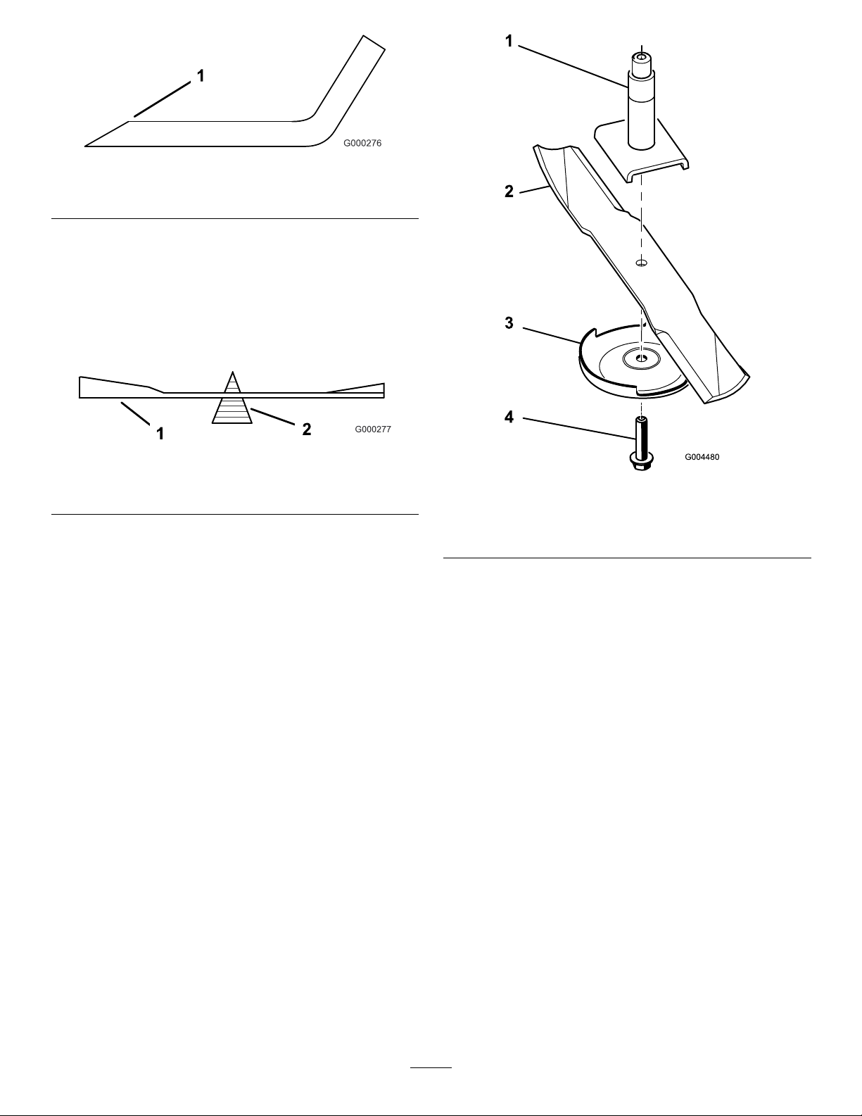
Figure69
1.Sharpenatoriginalangle
2.Checkthebalanceofthebladebyputtingitona
bladebalancer(Figure70).
Note:Ifthebladestaysinahorizontalposition,
thebladeisbalancedandcanbeused.Ifthe
bladeisnotbalanced,lesomemetaloffthe
endofthesailareaonly(Figure71).Repeatthis
procedureuntilthebladeisbalanced.
Figure70
1.Blade2.Balancer
g000276
g000277
g004480
Figure71
1.Spindle
2.Sailareaofblade
3.Anti-scalpplate
4.Bladebolt
InstallingtheBlades
1.Installthebladeontothespindleshaft(Figure
71).
Important:Thecurvedpartoftheblade
mustbepointingupwardtowardtheinside
ofthemowertoensurepropercutting.
2.Installtheanti-scalpplateandbladebolt(Figure
71).
Important:Thebladeboltshaveleft-hand
threads.
3.Torquethebladeboltto115to150N∙m(85to
110ft-lb).
38
AdjustingtheMowerPitch
Thefactorypresetsthepitchofthemowerdeckso
thatbackofthedeckishigherthanthefront.
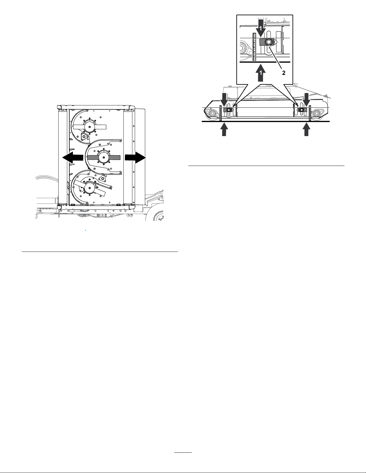
PreparingtheAdjustMowerPitch
Customerprovidedmaterial:awoodblock51mm
(2inch)
1.Foreachmowerdeckthatyouareadjusting
mowerpitch,alignthecentermowerblade
showninFigure72.
g256062
Figure73
1.4-7/8inchmeasurement2.Height-of-cutadjuster
2.Movetheheight-of-cutadjusterupordownuntil
youmeasure124mm(4-7/8inches)fromthe
topofadjusterblocktotheground(Figure73).
Figure72
2.Lowerthemowerdeckstotheground.
LevelingtheDeck
1.Loosenthenutthatsecurestheheight-of-cut
adjusterblock(Figure73).
3.Repeatsteps1and2attheotherheight-of-cut
adjusters.
SettingtheDeckPitch
g255552
Customerprovidedmaterial:woodspacerblock51
mm(2inches)
1.Workingatthebackofthemowerdeck,lift
therearapandalignthewoodblock51mm
(2inches)betweentherearendofthecenter
mowerbladeandtheground(Figure74).
Youshouldfeelslightdragasyousliptheblock
betweenthebladeandtheground.
•Ifthereistoomuchclearancebetweenthe
bladeandtheground,usethe4height-of-cut
adjusterstolowerthedeck.
•Ifyoucannotslipthewoodblockbetweenthe
bladeandtheground,usethe4height-of-cut
adjusterstoraisethedeck.
39
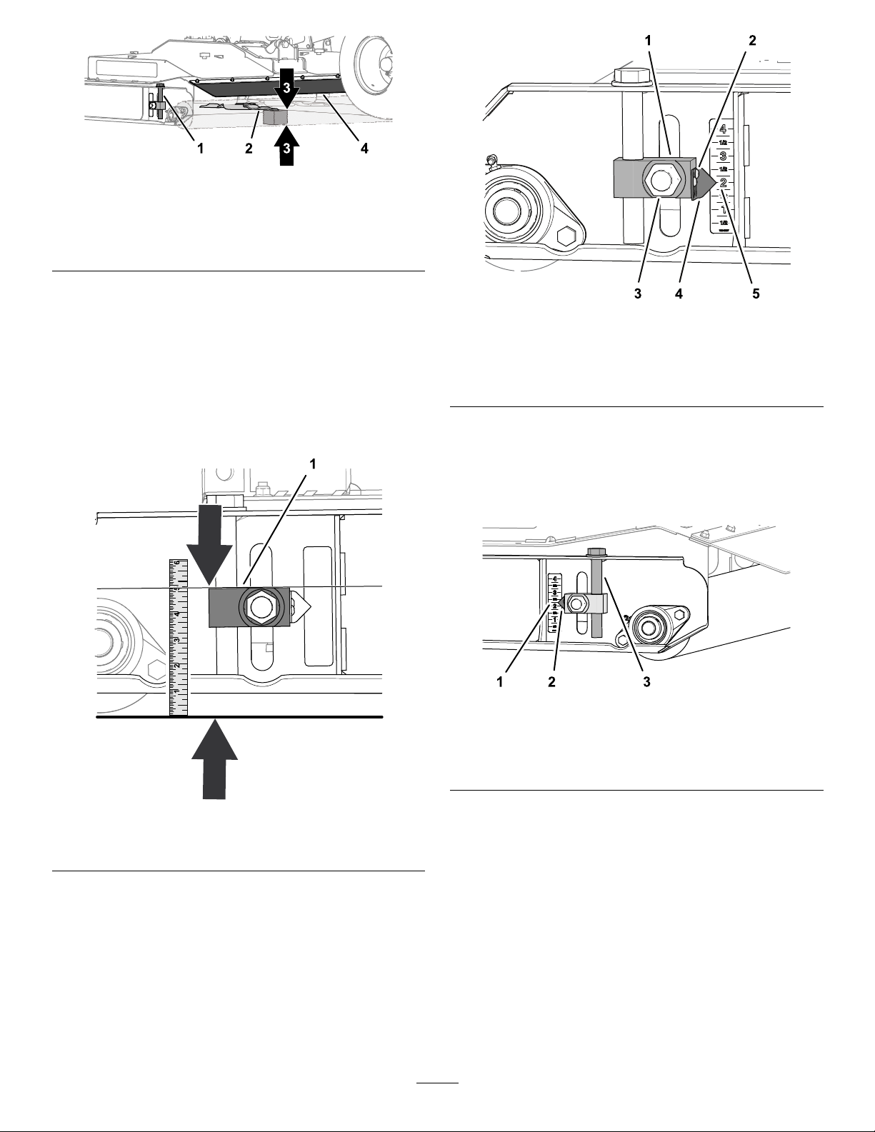
Figure74
g256063
1.Height-of-cutadjuster
2.Centermowerblade4.Rearap
3.Woodspacerblock51mm
(2inches)
2.Measurethedistancebetweentopofadjuster
blocktotheground(Figure75).
Rotatetheheight-of-cutadjusteruntilyou
achievethefollowingresults:
•Theheight-of-cutblocktotheground
measurementthesameatall4locations.
•Thewoodblockisasliptbetweenthe
centermowerbladeandtheground.
Figure76
1.Height-of-cutadjuster
2.Socket-headscrew5.2inchmark(decal)
3.Nut
4.Pointer
4.Repeatstep3attheotherheight-of-cut
adjusters.
5.Attherearroller,raisetheleftandrightheight
ofcutadjusterstothe2-1/4inchmarkonthe
decal(Figure77).
g256085
Figure75
1.Topoftheheight-of-cutadjuster
3.Loosenthe2socket-headscrewsthatsecure
thepointertotheheight-of-cutadjusterblock,
alignthepointertothe2inchmarkonthedecal,
andtightenthescrews(Figure76).
g256086
Figure77
1.2-1/4inchmark(decal)3.Height-of-cutadjuster
2.Pointer
g256087
6.Loosenthesocket-headscrewsthatsecurethe
(rearroller)
2pointerstotheheight-of-cutadjusterblock,
alignthepointerstothe2inchmarkonthe
decal,andtightenthescrews(Figure78).
40
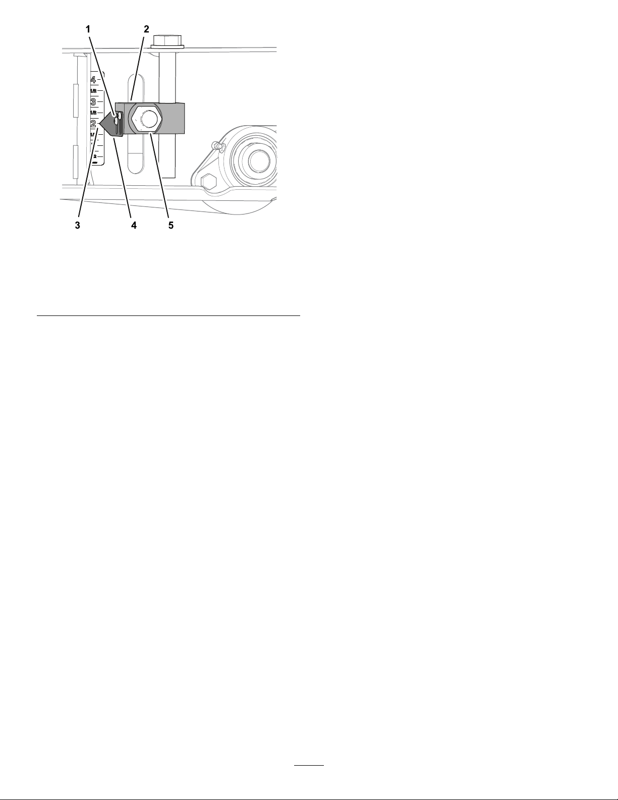
Figure78
1.Socket-headscrew
2.Height-of-cutadjuster
(rearroller)
3.2inchmark(decal)
7.Torquethe4nutsthatsecurethe4height-of-cut
adjusterblocks(Figure76andFigure78)forthe
frontandrearrollersto322to396N∙m(238to
292ft-lb).
4.Pointer
5.Nut
Storage
StoringtheMachine
Attheendofthemowingseasonorwhenthemoweris
storedforanextendedperiod,carryoutthefollowing
preventativemaintenance:
1.Parkthemachineonalevelsurface;engagethe
parkingbrake;shutofftheengine;removethe
key;andwaitforallmovementtostopbefore
leavingthemachine.
2.Cleanoffanydirtorgreasethatmayhave
accumulatedonthemachineoranyofthe
movingparts.
g256116
3.Lubricateallgreasettings.
4.Touchuppaintanyotherscratchesonthe
paintedsurfaces.
5.Replaceanymissingordamageddecals.
6.Whenpossible,storethemowerinsidea
dry,securebuilding.Ifinsidestorageisnot
available,coverthemachinewithaheavysheet
ortarpaulinandsecureittightly.
41

Notes:

CaliforniaProposition65WarningInformation
Whatisthiswarning?
Youmayseeaproductforsalethathasawarninglabellikethefollowing:
WARNING:CancerandReproductiveHarm—www.p65Warnings.ca.gov.
WhatisProp65?
Prop65appliestoanycompanyoperatinginCalifornia,sellingproductsinCalifornia,ormanufacturingproductsthatmaybesoldinorbroughtinto
California.ItmandatesthattheGovernorofCaliforniamaintainandpublishalistofchemicalsknowntocausecancer,birthdefects,and/orother
reproductiveharm.Thelist,whichisupdatedannually,includeshundredsofchemicalsfoundinmanyeverydayitems.ThepurposeofProp65isto
informthepublicaboutexposuretothesechemicals.
Prop65doesnotbanthesaleofproductscontainingthesechemicalsbutinsteadrequireswarningsonanyproduct,productpackaging,orliteraturewith
theproduct.Moreover,aProp65warningdoesnotmeanthataproductisinviolationofanyproductsafetystandardsorrequirements.Infact,the
CaliforniagovernmenthasclariedthataProp65warning“isnotthesameasaregulatorydecisionthataproductis‘safe’or‘unsafe.’”Manyofthese
chemicalshavebeenusedineverydayproductsforyearswithoutdocumentedharm.Formoreinformation,gotohttps://oag.ca.gov/prop65/faqs-view-all
AProp65warningmeansthatacompanyhaseither(1)evaluatedtheexposureandhasconcludedthatitexceedsthe“nosignicantrisklevel”;or(2)
haschosentoprovideawarningbasedonitsunderstandingaboutthepresenceofalistedchemicalwithoutattemptingtoevaluatetheexposure.
Doesthislawapplyeverywhere?
Prop65warningsarerequiredunderCalifornialawonly.ThesewarningsareseenthroughoutCaliforniainawiderangeofsettings,includingbutnot
limitedtorestaurants,grocerystores,hotels,schools,andhospitals,andonawidevarietyofproducts.Additionally ,someonlineandmailorder
retailersprovideProp65warningsontheirwebsitesorincatalogs.
.
HowdotheCaliforniawarningscomparetofederallimits?
Prop65standardsareoftenmorestringentthanfederalandinternationalstandards.TherearevarioussubstancesthatrequireaProp65warning
atlevelsthatarefarlowerthanfederalactionlimits.Forexample,theProp65standardforwarningsforleadis0.5μg/day,whichiswellbelow
thefederalandinternationalstandards.
Whydon’tallsimilarproductscarrythewarning?
•ProductssoldinCaliforniarequireProp65labellingwhilesimilarproductssoldelsewheredonot.
•AcompanyinvolvedinaProp65lawsuitreachingasettlementmayberequiredtouseProp65warningsforitsproducts,butothercompanies
makingsimilarproductsmayhavenosuchrequirement.
•TheenforcementofProp65isinconsistent.
•CompaniesmayelectnottoprovidewarningsbecausetheyconcludethattheyarenotrequiredtodosounderProp65;alackofwarningsfora
productdoesnotmeanthattheproductisfreeoflistedchemicalsatsimilarlevels.
WhydoesToroincludethiswarning?
Torohaschosentoprovideconsumerswithasmuchinformationaspossiblesothattheycanmakeinformeddecisionsabouttheproductstheybuyand
use.T oroprovideswarningsincertaincasesbasedonitsknowledgeofthepresenceofoneormorelistedchemicalswithoutevaluatingthelevelof
exposure,asnotallthelistedchemicalsprovideexposurelimitrequirements.WhiletheexposurefromToroproductsmaybenegligibleorwellwithinthe
“nosignicantrisk”range,outofanabundanceofcaution,TorohaselectedtoprovidetheProp65warnings.Moreover,ifTorodoesnotprovidethese
warnings,itcouldbesuedbytheStateofCaliforniaorbyprivatepartiesseekingtoenforceProp65andsubjecttosubstantialpenalties.
RevA

TheToroWarranty
ATwo-YearLimitedWarranty
ConditionsandProductsCovered
TheToroCompanyanditsafliate,T oroWarrantyCompany,pursuant
toanagreementbetweenthem,jointlywarrantyourT oroCommercial
product(“Product”)tobefreefromdefectsinmaterialsorworkmanship
fortwoyearsor1500operationalhours*,whicheveroccursrst.This
warrantyisapplicabletoallproductswiththeexceptionofAerators
(refertoseparatewarrantystatementsfortheseproducts).Wherea
warrantableconditionexists,wewillrepairtheProductatnocosttoyou
includingdiagnostics,labor,parts,andtransportation.Thiswarranty
beginsonthedatetheProductisdeliveredtotheoriginalretailpurchaser.
*Productequippedwithanhourmeter.
InstructionsforObtainingWarrantyService
YouareresponsiblefornotifyingtheCommercialProductsDistributoror
AuthorizedCommercialProductsDealerfromwhomyoupurchasedthe
Productassoonasyoubelieveawarrantableconditionexists.Ifyouneed
helplocatingaCommercialProductsDistributororAuthorizedDealer,or
ifyouhavequestionsregardingyourwarrantyrightsorresponsibilities,
youmaycontactusat:
ToroCommercialProductsServiceDepartment
ToroWarrantyCompany
811 1LyndaleAvenueSouth
Bloomington,MN55420-1196
952–888–8801or800–952–2740
E-mail:commercial.warranty@toro.com
OwnerResponsibilities
AstheProductowner,youareresponsibleforrequiredmaintenanceand
adjustmentsstatedinyourOperator'sManual.Failuretoperformrequired
maintenanceandadjustmentscanbegroundsfordisallowingawarranty
claim.
ItemsandConditionsNotCovered
Notallproductfailuresormalfunctionsthatoccurduringthewarranty
periodaredefectsinmaterialsorworkmanship.Thiswarrantydoesnot
coverthefollowing:
•Productfailureswhichresultfromtheuseofnon-Tororeplacement
parts,orfrominstallationanduseofadd-on,ormodiednon-Toro
brandedaccessoriesandproducts.Aseparatewarrantymaybe
providedbythemanufactureroftheseitems.
•Productfailureswhichresultfromfailuretoperformrecommended
maintenanceand/oradjustments.Failuretoproperlymaintainyour
ToroproductpertheRecommendedMaintenancelistedinthe
Operator’sManualcanresultinclaimsforwarrantybeingdenied.
•ProductfailureswhichresultfromoperatingtheProductinanabusive,
negligent,orrecklessmanner.
•Partssubjecttoconsumptionthroughuseunlessfoundtobedefective.
Examplesofpartswhichareconsumed,orusedup,duringnormal
Productoperationinclude,butarenotlimitedto,brakepadsand
linings,clutchlinings,blades,reels,rollersandbearings(sealedor
greasable),bedknives,sparkplugs,castorwheelsandbearings,tires,
lters,belts,andcertainsprayercomponentssuchasdiaphragms,
nozzles,andcheckvalves,etc.
•Failurescausedbyoutsideinuence.Conditionsconsideredtobe
outsideinuenceinclude,butarenotlimitedto,weather,storage
practices,contamination,useofunapprovedfuels,coolants,lubricants,
additives,fertilizers,water,orchemicals,etc.
•Failureorperformanceissuesduetotheuseoffuels(e.g.gasoline,
diesel,orbiodiesel)thatdonotconformtotheirrespectiveindustry
standards.
•Normalnoise,vibration,wearandtear,anddeterioration.
•Normal“wearandtear”includes,butisnotlimitedto,damagetoseats
duetowearorabrasion,wornpaintedsurfaces,scratcheddecalsor
windows,etc.
Parts
Partsscheduledforreplacementasrequiredmaintenancearewarranted
fortheperiodoftimeuptothescheduledreplacementtimeforthatpart.
Partsreplacedunderthiswarrantyarecoveredforthedurationofthe
originalproductwarrantyandbecomethepropertyofT oro.T orowillmake
thenaldecisionwhethertorepairanyexistingpartorassemblyorreplace
it.T oromayuseremanufacturedpartsforwarrantyrepairs.
DeepCycleandLithium-IonBatteryWarranty:
DeepcycleandLithium-Ionbatterieshaveaspeciedtotalnumberof
kilowatt-hourstheycandeliverduringtheirlifetime.Operating,recharging,
andmaintenancetechniquescanextendorreducetotalbatterylife.Asthe
batteriesinthisproductareconsumed,theamountofusefulworkbetween
chargingintervalswillslowlydecreaseuntilthebatteryiscompletelyworn
out.Replacementofwornoutbatteries,duetonormalconsumption,
istheresponsibilityoftheproductowner.Batteryreplacementmaybe
requiredduringthenormalproductwarrantyperiodatowner’sexpense.
Note:(Lithium-Ionbatteryonly):ALithium-Ionbatteryhasapartonly
proratedwarrantybeginningyear3throughyear5basedonthetime
inserviceandkilowatthoursused.RefertotheOperator'sManualfor
additionalinformation.
MaintenanceisatOwner’sExpense
Enginetune-up,lubrication,cleaningandpolishing,replacementoflters,
coolant,andcompletingrecommendedmaintenancearesomeofthe
normalservicesT oroproductsrequirethatareattheowner’sexpense.
GeneralConditions
RepairbyanAuthorizedToroDistributororDealerisyoursoleremedy
underthiswarranty.
NeitherTheToroCompanynorToroWarrantyCompanyisliablefor
indirect,incidentalorconsequentialdamagesinconnectionwiththe
useoftheToroProductscoveredbythiswarranty,includingany
costorexpenseofprovidingsubstituteequipmentorserviceduring
reasonableperiodsofmalfunctionornon-usependingcompletion
ofrepairsunderthiswarranty.ExceptfortheEmissionswarranty
referencedbelow,ifapplicable,thereisnootherexpresswarranty .All
impliedwarrantiesofmerchantabilityandtnessforusearelimitedto
thedurationofthisexpresswarranty.
Somestatesdonotallowexclusionsofincidentalorconsequential
damages,orlimitationsonhowlonganimpliedwarrantylasts,sotheabove
exclusionsandlimitationsmaynotapplytoyou.Thiswarrantygivesyou
speciclegalrights,andyoumayalsohaveotherrightswhichvaryfrom
statetostate.
Noteregardingenginewarranty:
TheEmissionsControlSystemonyourProductmaybecoveredby
aseparatewarrantymeetingrequirementsestablishedbytheU.S.
EnvironmentalProtectionAgency(EP A)and/ortheCaliforniaAirResources
Board(CARB).Thehourlimitationssetforthabovedonotapplytothe
EmissionsControlSystemWarranty.RefertotheEngineEmissionControl
WarrantyStatementsuppliedwithyourproductorcontainedintheengine
manufacturer’sdocumentationfordetails
CountriesOtherthantheUnitedStatesorCanada
CustomerswhohavepurchasedT oroproductsexportedfromtheUnitedStatesorCanadashouldcontacttheirT oroDistributor(Dealer)toobtain
guaranteepoliciesforyourcountry ,province,orstate.IfforanyreasonyouaredissatisedwithyourDistributor'sserviceorhavedifcultyobtaining
guaranteeinformation,contacttheT oroimporter.
374-0253RevD
 Loading...