

Page 1
FormNo.3397-630RevA
Groundsmaster
®
3604-Wheel
DriveMulti-PurposeMachine
ModelNo.31200—SerialNo.316000001andUp
Registeratwww.T oro.com.
OriginalInstructions(EN)
*3397-630*A
Page 2
WARNING
CALIFORNIA
Proposition65Warning
Dieselengineexhaustandsomeofits
constituentsareknowntotheStateof
Californiatocausecancer,birthdefects,
andotherreproductiveharm.
GenuineT orosparkarrestersareapprovedbytheUSDA
ForestryService.
ItisaviolationofCaliforniaPublicResourceCode
Section4442or4443touseoroperatetheengineonany
forest-covered,brush-covered,orgrass-coveredlandunless
theengineisequippedwithasparkarrester,asdenedin
Section4442,maintainedineffectiveworkingorderorthe
engineisconstructed,equipped,andmaintainedforthe
preventionofre.
Introduction
Thismachineisaride-on,rotary-blademachineintended
tobeusedbyprofessional,hiredoperatorsincommercial
applications.Itisprimarilydesignedforcuttinggrass
onwell-maintainedlawnsinparks,sportselds,andon
commercialgrounds.Itisnotdesignedforcuttingbrushor
mowinggrassandothergrowthalongsidehighways,orfor
agriculturaluses.
Readthisinformationcarefullytolearnhowtooperateand
maintainyourproductproperlyandtoavoidinjuryand
productdamage.Youareresponsibleforoperatingthe
productproperlyandsafely.
YoumaycontactTorodirectlyatwww .Toro.comforproduct
safetyandoperationtrainingmaterials,accessoryinformation,
helpndingadealer,ortoregisteryourproduct.
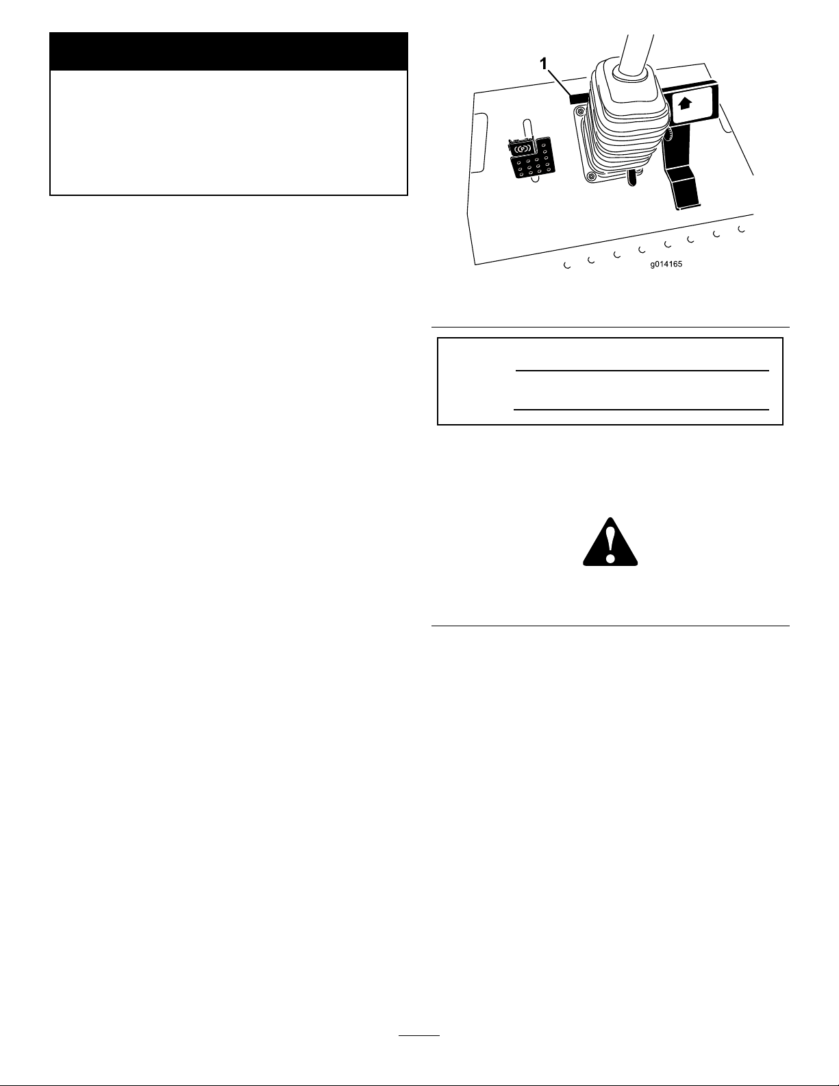
Figure1
1.Modelandserialnumberlocation
ModelNo.
SerialNo.
Thismanualidentiespotentialhazardsandhassafety
messagesidentiedbythesafety-alertsymbol(Figure2),
whichsignalsahazardthatmaycauseseriousinjuryordeath
ifyoudonotfollowtherecommendedprecautions.
Figure2
1.Safety-alertsymbol
Thismanualalsouses2wordstohighlightinformation.
Importantcallsattentiontospecialmechanicalinformation
andNoteemphasizesgeneralinformationworthyofspecial
attention.
Wheneveryouneedservice,genuineT oroparts,oradditional
information,contactanAuthorizedServiceDealerorToro
CustomerServiceandhavethemodelandserialnumbersof
yourproductready.Figure1identiesthelocationofthe
modelandserialnumbersontheproduct.Writethenumbers
inthespaceprovided.
©2015—TheToro®Company
8111LyndaleAvenueSouth
Bloomington,MN55420
Contactusatwww.Toro.com.
2
PrintedintheUSA
AllRightsReserved
Page 3

Contents
Safety...........................................................................4
GeneralSafety.........................................................4
SafetyandInstructionalDecals.................................4
Setup............................................................................9
1AdjustingtheROPS..............................................9
2CheckingtheTirePressure.....................................9
3CheckingtheFluidLevels.....................................10
ProductOverview.........................................................10
Controls...............................................................10
Specications........................................................14
Attachments/Accessories........................................15
BeforeOperation......................................................15
BeforeOperationSafety..........................................15
CheckingtheEngine-OilLevel.................................16
CheckingtheCoolingSystem...................................16
CheckingtheHydraulicSystem................................16
FillingtheFuelTank...............................................16
UsingtheRolloverProtectionSystem(ROPS)............17
TheSafetyInterlockSystem.....................................18
SelectingtheSteeringMode.....................................18
PositioningtheStandardSeat...................................19
PositioningtheDeluxeSeat......................................19
Raising/LoweringtheSeat.......................................20
DuringOperation.....................................................21
DuringOperationSafety.........................................21
ThinkSafetyFirst...................................................22
StartingandStoppingtheEngine..............................22
DrivingtheMachine...............................................23
StoppingtheMachine.............................................23
OperatingtheMower..............................................23
OperatingTips......................................................24
AfterOperation........................................................24
AfterOperationSafety............................................24
PushingtheMachinebyHand..................................24
HaulingtheMachine...............................................25
Maintenance.................................................................26
RecommendedMaintenanceSchedule(s)......................26
DailyMaintenanceChecklist....................................27
PremaintenanceProcedures........................................28
Pre-MaintenanceSafety...........................................28
PreparingtheMachineforMaintenance.....................29
UsingtheHoodPropRod.......................................29
Lubrication...............................................................30
GreasingtheBearingsandBushings..........................30
EngineMaintenance..................................................30
ServicingtheAirCleaner.........................................30
CheckingtheEngine-OilLevel.................................32
ChangingtheEngineOilandFilter...........................32
ServicingtheDieselParticulateFilter(DPF)...............33
ServicingtheDieselOxidationCatalyst
(DOC)..............................................................33
FuelSystemMaintenance...........................................34
ServicingtheWaterSeparator...................................34
ServicingtheEngineFuelFilter................................34
CheckingtheFuelLinesandConnections..................34
CleaningtheFuelPick-UpTubeScreen.....................34
ElectricalSystemMaintenance....................................35
ElectricalSystemSafety...........................................35
CheckingtheFuses.................................................35
ServicingtheBattery...............................................35
StoringtheBattery..................................................36
DriveSystemMaintenance.........................................36
CheckingtheTirePressure......................................36
CorrectingSteeringMisalignment.............................36
CoolingSystemMaintenance......................................37
CoolingSystemSafety.............................................37
CheckingtheCoolingSystem..................................37
CleaningtheRadiator..............................................37
BrakeMaintenance....................................................38
AdjustingtheServiceBrakes....................................38
AdjustingtheParkingBrake.....................................39
BeltMaintenance......................................................39
CheckingtheAlternatorBelt...................................39
ControlsSystemMaintenance.....................................40
AdjustingtheTractionDriveforNeutral....................40
AdjustingtheMaximumGroundSpeed.....................40
AdjustingtheMow-SpeedLimiter.............................41
HydraulicSystemMaintenance....................................42
HydraulicSystemSafety..........................................42
CheckingtheHydraulicSystem................................42
ChangingtheHydraulicFluidAndFilter....................42
Cleaning...................................................................43
WasteDisposal.......................................................43
Storage........................................................................44
PreparingtheEngine..............................................44
PreparingtheMachine............................................44
3
Page 4
Safety
•Donotputyourhandsorfeetnearmovingcomponents
ofthemachine.
ThismachinehasbeendesignedinaccordancewithENISO
5395:2013andANSIB71.4-2012.
Improperuseormaintenancebytheoperatororownercan
resultininjury.Toreducethepotentialforinjury,comply
withthesesafetyinstructionsandalwayspayattentionto
thesafetyalertsymbol,whichmeansCaution,Warning,or
Danger—personalsafetyinstruction.Failuretocomplywith
theinstructionmayresultinpersonalinjuryordeath.
GeneralSafety
Thisproductiscapableofamputatinghandsandfeetand
ofthrowingobjects.Alwaysfollowallsafetyinstructionsto
avoidseriouspersonalinjury.
Usingthisproductforpurposesotherthanitsintendeduse
couldprovedangeroustoyouandbystanders.
•ReadandunderstandthecontentsofthisOperator’ sManual
beforeyoustarttheengine.Ensurethateveryoneusing
thisproductknowshowtouseitandunderstandsthe
warnings.
•Donotoperatethemachinewithoutallguardsandother
safetyprotectivedevicesinplaceandworkingonthe
machine.
•Keepclearofanydischargeopening.Keepbystandersa
safedistancefromthemachine.
•Keepchildrenoutoftheoperatingarea.Neverallow
childrentooperatethemachine.
•Stopthemachineandshutofftheenginebeforeservicing,
fueling,oruncloggingthemachine.
Improperlyusingormaintainingthemachinecanresult
ininjury.Toreducethepotentialforinjury,complywith
thesesafetyinstructionsandalwayspayattentiontothe
safety-alertsymbol,whichmeansCaution,Warning,or
Danger—personalsafetyinstruction.Failuretocomplywith
theseinstructionsmayresultinpersonalinjuryordeath.
Youcanndadditionalitemsofsafetyinformationintheir
respectivesectionsthroughoutthismanual.
SafetyandInstructionalDecals
Safetydecalsandinstructionsareeasilyvisibletotheoperatorandarelocatednearanyareaofpotential
danger.Replaceanydecalthatisdamagedorlost.
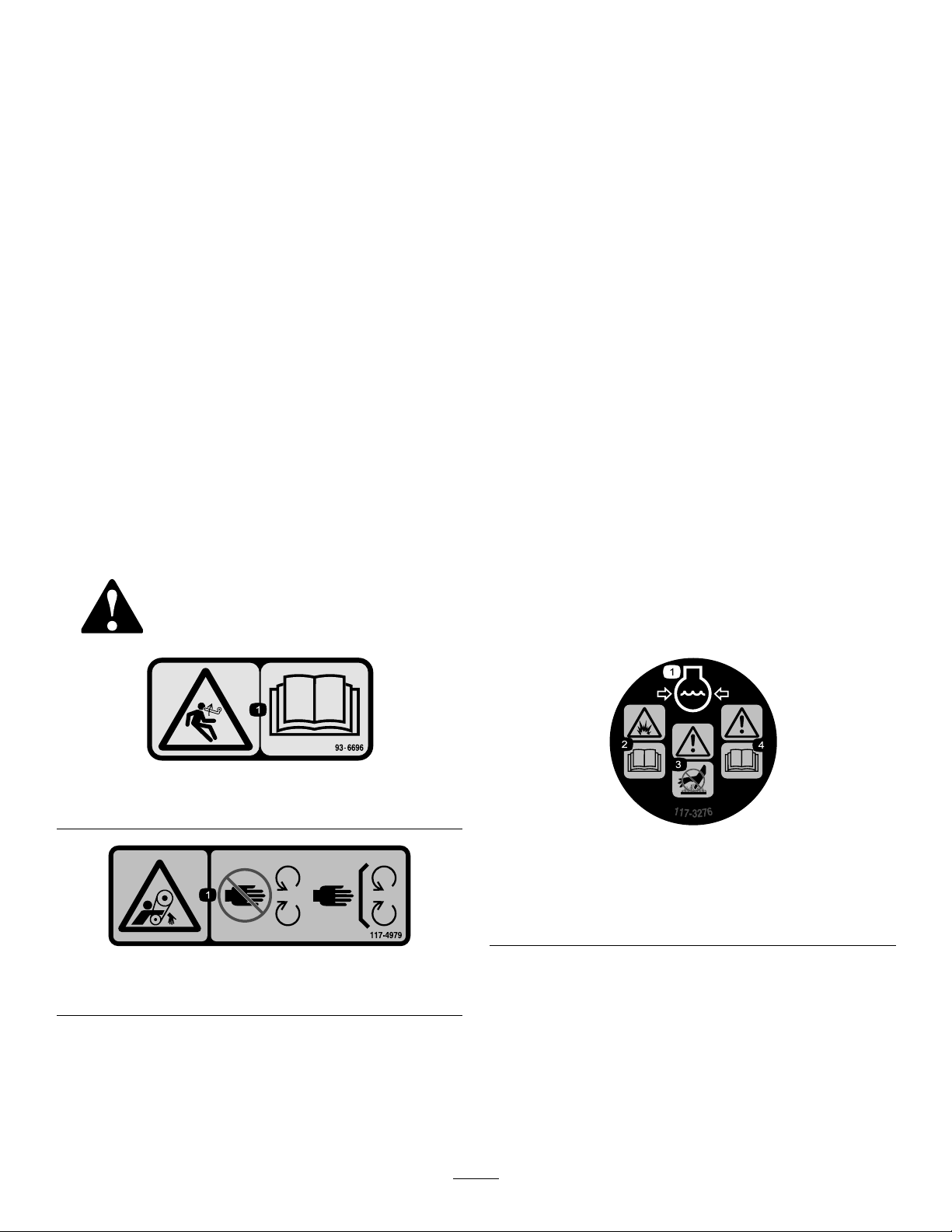
93–6696
1.Storedenergyhazard—readtheOperator'sManual.
117–4979
1.Rotatingbelt—Keepguardinplace
1.Enginecoolantunder
pressure
2.Explosionhazard—read
theOperator'sManual.
117-3276
3.Warning—donottouchthe
hotsurface.
4.Warning—readthe
Operator'sManual.
4
Page 5
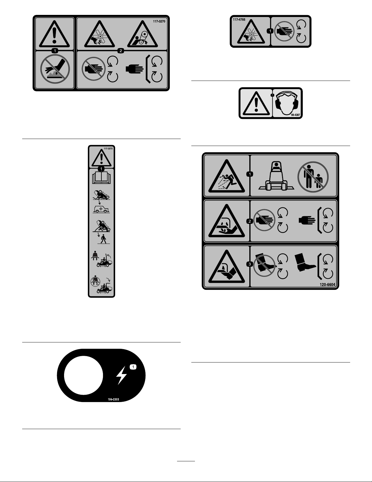
117-3270
1.Warning—donottouchthehotsurface.
2.Cutting/dismembermenthazard,hand;entanglement
hazard,belt—stayawayfrommovingparts,keepallguards
andshieldsinplace.
117-4766
1.Cutting/dismembermenthazard;fan—stayawayfrom
movingparts,keepallguardsandshieldsinplace.
98-4387
1.Warning—wearhearingprotection.
117-3272
1.Warning—readtheOperator'sManual;failuretousthe
rolloverprotectionsystem(ROPS)canresultininjuryin
theeventofarollover;wearaseatbeltwhenaROPSisin
place,donotwearaseatbeltwhenROPSislowered.
106-2353
1.Electricalpowerpoint
120-6604
1.Thrownobjecthazard—keepbystandersawayfromthe
machine.
2.Cutting/dismembermenthazardofhand,mower
blade—stayawayfrommovingparts,keepallguardsand
shieldsinplace.
3.Cutting/dismembermenthazardoffoot,mowerblade—stay
awayfrommovingparts,keepallguardsandshieldsin
place.
5
Page 6
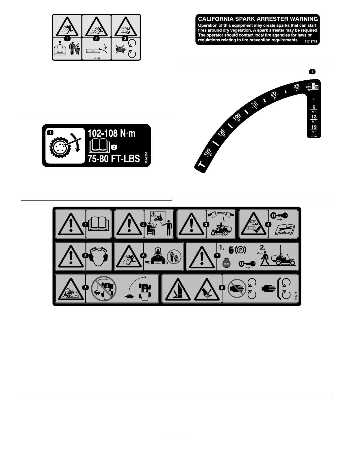
107-2908
1.Thrownobjecthazard—keepbystandersasafedistance
fromthemachine.
2.Thrownobjecthazard—donotoperatethemowerwiththe
deectoruporremoved,keepthedeectorinplace.
3.Cutting/dismembermenthazardofhandorfoot,mower
blade—stayawayfrommovingparts.
106-9206
1.Wheeltorquespecications
2.ReadtheOperator'sManual.
117–2718
115-0492
1.Heightofcut(topnumber:mm,bottomnumber:inches)
117-3273
1.Warning—readtheOperator'sManual.6.Thrownobjecthazard—keepbystandersasafedistancefrom
2.Warning—donotoperatethismachineunlessyouaretrained.7.Warning—locktheparkingbrake,stoptheengineandremove
3.Warning—weartheseatbeltwhenseatedintheoperator's
position.
4.Cutting/dismembermenthazardofhandorfoot—removethe
ignitionkeyandreadtheinstructionsbeforeservicingor
performingmaintenance.
5.Warning—wearhearingprotection.
themachine.
theignitionkeybeforeleavingthemachine.
8.Tippinghazard—lowerthecuttingunitwhendrivingdown
slopes;slowmachinebeforeturning,donotturnathigh
speeds
9.Cuttinghazardofhandorfoot—stayawayfrommovingparts;
keepallguardsinplace.
6
Page 7

107-2916
1.Removetheignitionkeyandreadthe
Operator'sManualbeforeservicingor
performingmaintenance.
2.Thrownobjecthazard—donotoperate
themowerwiththedeectorupor
removed,keepthedeectorinplace;
keepbystandersasafedistancefrom
themachine.
3.Cutting/dismembermenthazardof
125-4399
1.Lowerthedeck
2.Raisethedeck5.Engine—stop8.2-wheelsteering
3.Fast6.Engine—run9.4-wheelsteering
4.Slow
7.Engine—start
handorfoot,mowerblade—stayaway
frommovingparts.
1.ReadtheOperator’sManualformoreinformationonservicingthemachine.
131–1946
7
Page 8

BatterySymbols
Someorallofthesesymbolsareonyourbattery
1.Explosionhazard
2.Nore,opename,or
smoking
3.Causticliquid/chemical
burnhazard
4.Weareyeprotection9.Flusheyesimmediately
5.ReadtheOperator's
Manual.
6.Keepbystandersasafe
7.Weareyeprotection;
8.Batteryacidcancause
10.Containslead;donot
distancefromthebattery.
explosivegasescan
causeblindnessandother
injuries.
blindnessorsevereburns.
withwaterandgetmedical
helpfast.
discard
8
Page 9
Setup
LooseParts
Usethechartbelowtoverifythatallpartshavebeenshipped.
ProcedureDescription
1
2
3
Nopartsrequired
Nopartsrequired
Nopartsrequired
MediaandAdditionalParts
Description
Operator'sManual
Engineoperator'smanual1
PartsCatalog
OperatorTrainingMaterial
1
Qty.
Qty.
–
–
–
1
1
1
Readthemanualbeforeoperatingthemachine.
Readthemanualbeforeoperatingthemachine.
UsethePartsCatalogtoreferencepartnumbers.
Reviewbeforeoperatingmachine
AdjusttheROPS.
Checkthetirepressure.
Checkthelevelsofthehydraulicuid,
engineoil,andcoolant.
Use
Use
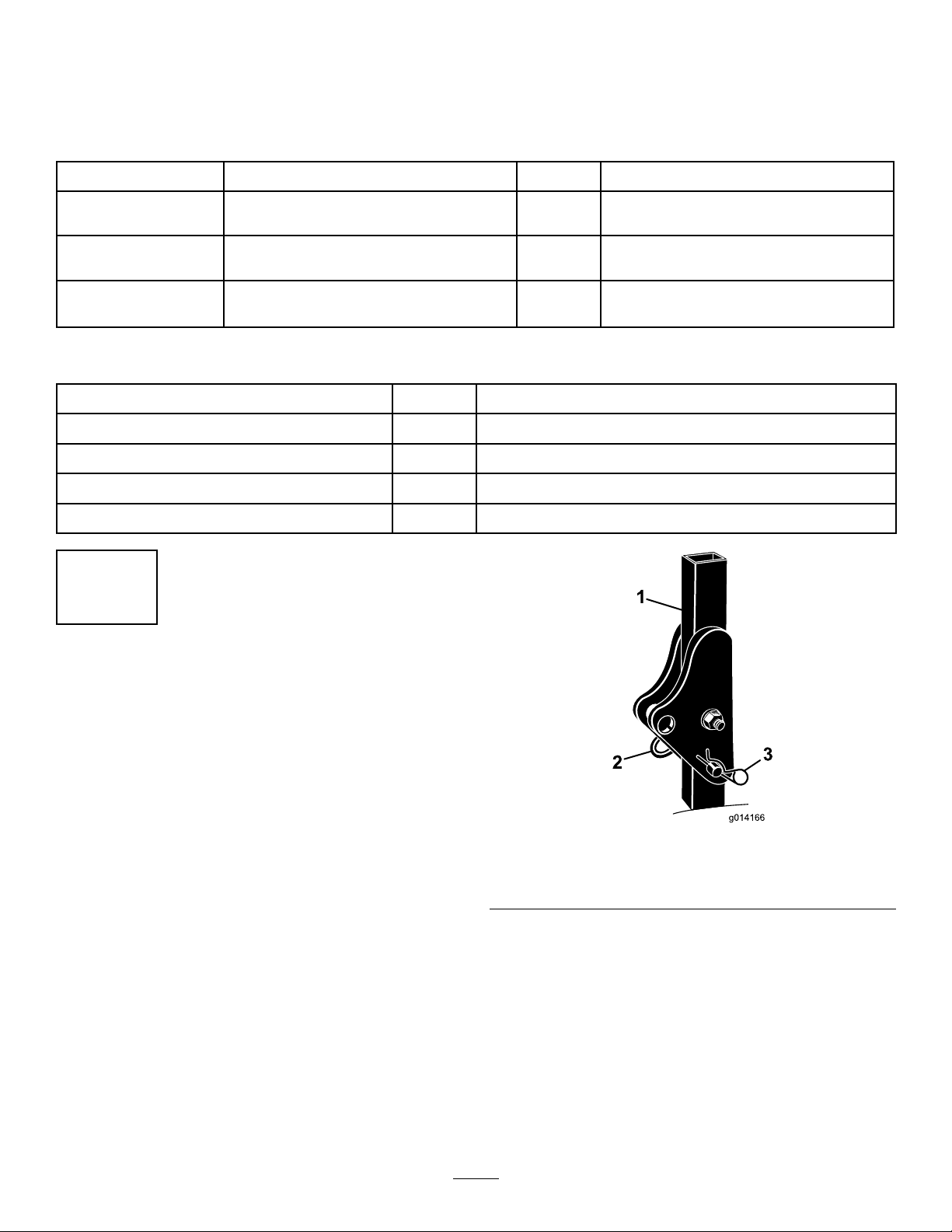
AdjustingtheROPS
NoPartsRequired
Procedure
1.Removethehairpincotterpinsandthepinsfromthe
rollbar(Figure3).
2.Raisetherollbartotheuprightpositionandinstallthe
2pinsandsecurethemwiththehairpincotterpins
(Figure3).
Note:Ifyoumustlowertherollbar,pushthebar
forwardtorelievepressureonthepins,removethe
pins,lowerthebarslowly,andsecureitwiththepinsso
thatitdoesnotdamagethehood.
Figure3
1.Rollbar3.Hairpincotter
2.Pin
9
Page 10
ProductOverview
2
CheckingtheTirePressure
NoPartsRequired
Procedure
Thetiresareoverinatedforshipping.Therefore,release
someoftheairtoreducethepressure.Checkthetire
pressure;refertoCheckingtheTirePressure(page36).
3
CheckingtheFluidLevels
NoPartsRequired
Procedure
Controls
Becomefamiliarwithallthecontrolsbeforeyoustartthe
engineandoperatethemachine.
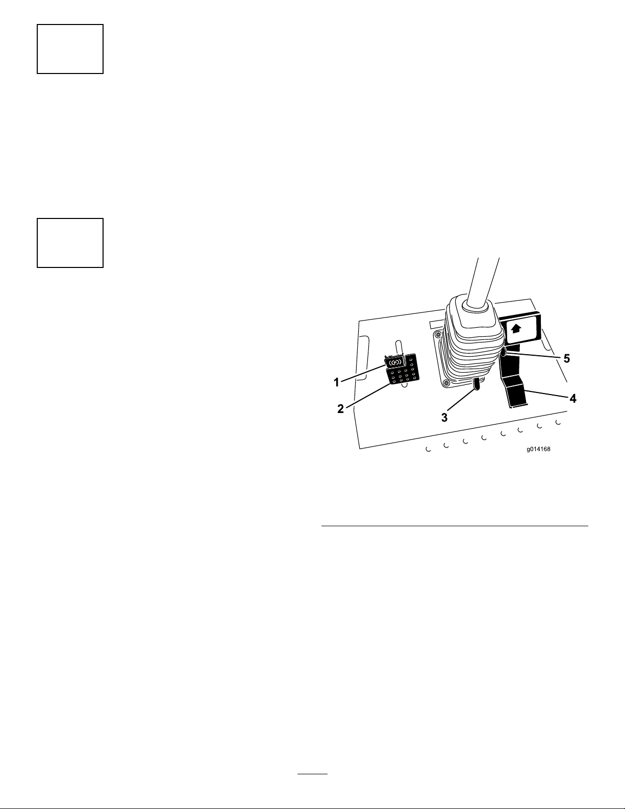
TractionPedal
Thetractionpedal(Figure4)controlstheforwardandreverse
operation.Pressthetopofthepedaltomoveforwardandthe
bottomtomoverearward.Groundspeeddependsonhow
faryoupressthepedal.Fornoload,maximumgroundspeed,
fullypressthepedalwhilethethrottleisintheFASTposition.
Tostopthemachine,reduceyourfootpressureonthe
tractionpedalandallowthepedaltoreturntotheCENTER
position.
1.Checkthelevelofthehydraulicuidbeforestarting
theengine;refertoCheckingtheHydraulicSystem
(page42).
2.Checktheleveloftheengineoilbeforestartingthe
engine;refertoCheckingtheEngine-OilLevel(page
32).
3.Checkthecoolingsystembeforestartingtheengine;
refertoCheckingtheCoolingSystem(page37).
Figure4
1.Parkingbrake4.Tractionpedal
2.Brakepedal5.Mow-speedlimiter
3.Tilt-steeringpedal
Mow-SpeedLimiter
Themow-speedlimiter(Figure4)limitsthetractionspeedof
themachinewhenyouipitforward.
BrakePedal
Usethebrakepedalinconjunctionwiththebrake-pedallatch
toengageanddisengagetheparkingbrake(Figure4).Tostop
themachine,releasethetractionpedalandallowittoreturn
totheCENTERposition.Thebrakecanassistinstoppingin
anemergencysituation.
ParkingBrake
Toengagetheparkingbrake,pushdownonthebrakepedal
andpressthetopforwardtolatchit(Figure4).Toreleasethe
10
Page 11

parkingbrake,pressthebrakepedaluntiltheparking-brake
2
G026098
1
567
43
latchretracts.
Tilt-SteeringPedal
Totiltthesteeringwheeltowardyou,pressthefootpedal
downandpullthesteeringtowertowardyoutothemost
comfortablepositionandthenreleasethepedal(Figure4).
Engine-SpeedSwitch
Theengine-speedswitch(Figure5)has2modestochange
theenginespeed.Bymomentarilytappingtheswitch,you
canincreaseordecreasetheenginespeedinincrementsof
100rpm.Pressandholdtheswitchtosettheenginespeed
directlytohighorlowidle,dependingonwhichendofthe
switchyoupress.
PowerPoint
Thepowerpointisa12-voltpowersupplyforelectronic
devices(Figure5).
Important:Ifthemowerdeckshutsdownandthe
InfoCentertemperature-warningiconison,pushthe
PTOknobdown,drivetoasafeatarea,movethe
throttlelevertotheSLOWposition,allowthetraction
pedaltomovetotheNEUTRALposition,andsetthe
parkingbrake.Allowtheenginetoidleforseveral
minuteswhileitcoolstoasafelevel.Shutofftheengine
andcheckthecoolingsystem;refertoCheckingthe
CoolingSystem(page37).
FuelGauge
Thefuelgauge(Figure6)indicatesthefuellevelremaining
inthefueltank.
Figure5
1.InfoCenter
2.Powertake-off(PTO)
Switch
3.Engine-speedswitch
4.Steeringselectorswitch
5.Powerpoint
6.Ignitionswitch
7.Deckliftswitch
InfoCenter
TheInfoCenterLCDdisplayshowstheoperatingstatus,
variousdiagnostics,andotherinformationaboutthemachine
(Figure5).
IgnitionSwitch
Theignitionswitchhas3positions:Off,On/Preheat,and
Start(Figure5).
PowerTake-Off(PTO)Switch
Thepowertake-off(PTO)switchstartsandstopsthemower
blades(Figure5).
Figure6
1.Fuelgauge2.Fuel-tankcap
SteeringSelectorSwitch
Pressthesteeringselectorswitchtothereartoengage4-wheel
steeringandforwardtoreturnto2-wheelsteering(Figure5).
11
Page 12
UsingtheInfoCenterLCDDisplay
1
g020650
2
3
4
TORO
InfoCenterIconDescription
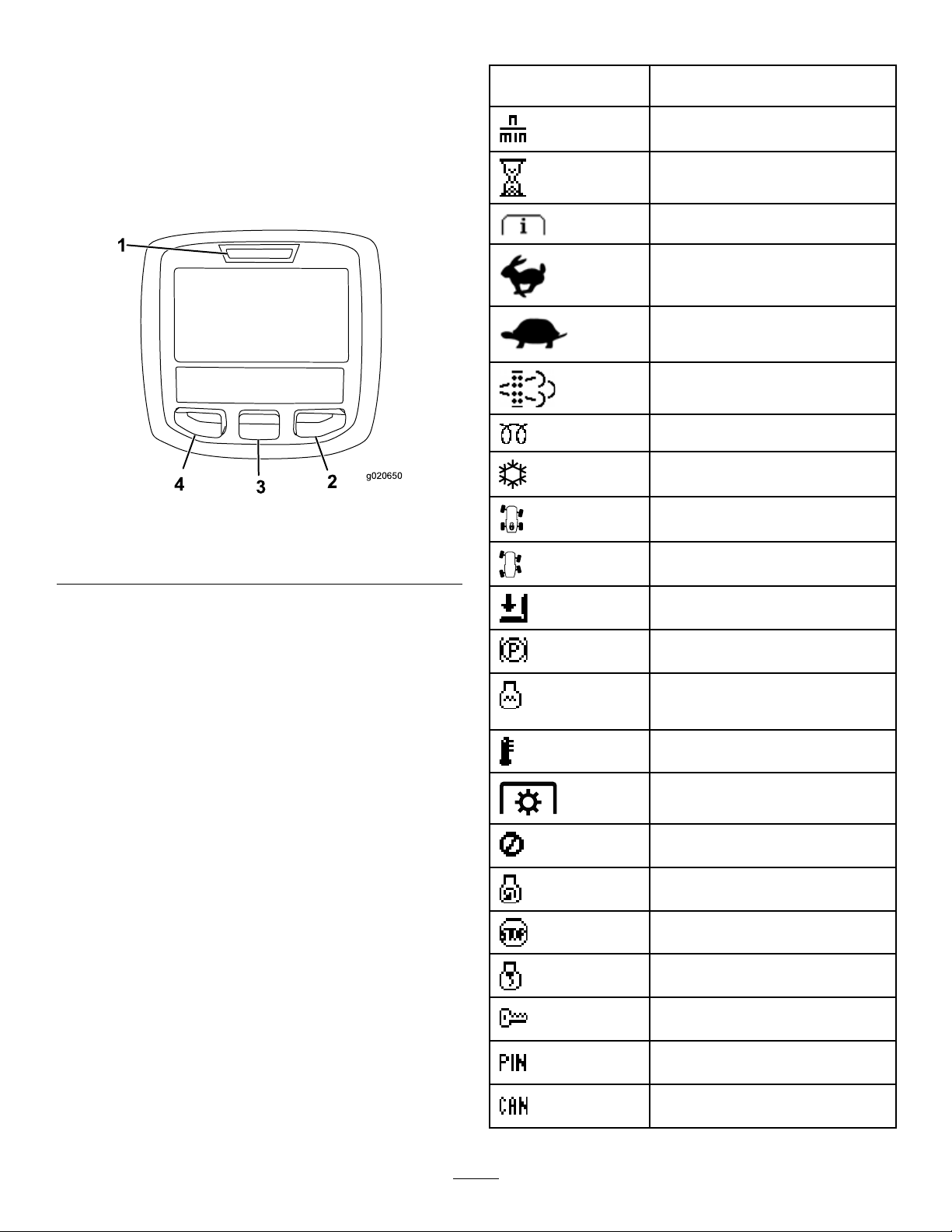
TheInfoCenterLCDdisplayshowsinformationaboutyour
machinesuchastheoperatingstatus,variousdiagnostics
andotherinformationaboutthemachine(Figure7).There
isasplashscreenandmaininformationscreenofthe
InfoCenter.Youcanswitchbetweenthesplashscreenand
maininformationscreen,atanytime,bypressinganyof
theInfoCenterbuttonsandthenselectingtheappropriate
directionalarrow .
Figure7
1.Indicatorlight3.Middlebutton
2.Rightbutton
4.Leftbutton
SERVICEDUE
Indicateswhenscheduledservice
shouldbeperformed
Enginerpm/status—indicatesthe
enginerpm
Hourmeter
Infoicon
Fast
Slow
Stationaryregenerationrequired
Glowplugsareactive
AC
2-wheelsteer
4-wheelsteer
•Leftbutton,menuaccess/backbutton—pressthisbutton
Operatormustsitinseat
toaccesstheInfoCentermenus.Youcanuseittoback
outofanymenuyouarecurrentlyusing.
Parkingbrakeindicator—indicates
whentheparkingbrakeisset
•Middlebutton—usethisbuttontoscrolldownmenus.
•Rightbutton—usethisbuttontoopenamenuwherea
rightarrowindicatesadditionalcontent.
Note:Thepurposeofeachbuttonmaychangedepending
onwhatisrequiredatthetime.Eachbuttonwillbelabeled
withanicondisplayingitscurrentfunction.
CoolantTemperature-indicatesthe
enginecoolanttemperatureineither
°Cor°F
Temperature(hot)
PTOisengaged
Deniedornotallowed
Enginestart
Stoporshutdown
Engine
Keyswitch
PINpasscode
CANbus
12
Page 13
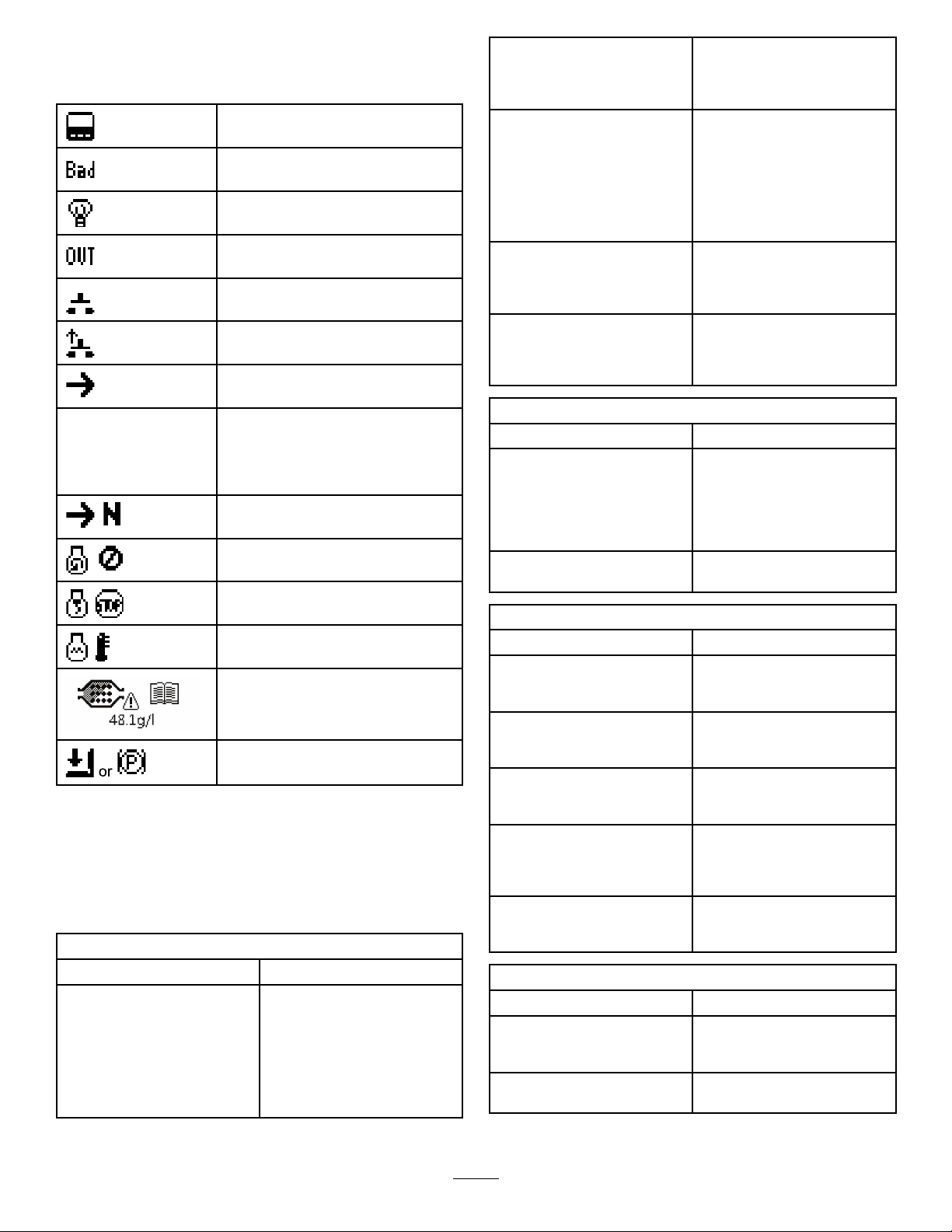
InfoCenterIconDescription(cont'd.)
InfoCenter
Badorfailed
Bulb
OutputofTECcontrollerorcontrol
wireinharness
Switch
Operatormustreleaseswitch
Operatorshouldchangetoindicated
state
Symbolsareoften
combinedtoform
sentences.Some
examplesareshown
below
Operatorshouldputmachinein
Neutral
Enginestartdenied
Engineshutdown
Enginecoolanttoohot
DPFashaccumulationnotication.
RefertoServicingtheDiesel
ParticulateFilter(DPF)(page33)for
details.
Sitdownorsetparkingbrake
UsingtheMenus
ToaccesstheInfoCentermenusystem,pressthemenuaccess
buttonwhileatthemainscreen.Thiswillbringyoutothe
mainmenu.Refertothefollowingtablesforasynopsisof
theoptionsavailablefromthemenus:
MainMenu
MenuItemDescription
FaultsTheFaultsmenucontains
alistoftherecentmachine
faults.RefertotheService
ManualoryourAuthorized
ToroDistributorformore
informationontheFaults
menuandtheinformation
containedthere.
ServiceTheServicemenucontains
DiagnosticsTheDiagnosticsmenu
SettingsTheSettingsmenuallows
AboutTheAboutmenuliststhe
Service
MenuItemDescription
Hours
Counts
Diagnostics
MenuItemDescription
PTOIndicatestheinputs,qualiers,
EngineRun
Decks
SteerModeIndicatestheinputs,qualiers,
MachineInput
Settings
MenuItemDescription
Units
Language
informationonthemachine
suchashoursofusecounters
andothersimilarnumbers.
displaysthestateofeach
machineswitch,sensorand
controloutput.Y oucanuse
thistotroubleshootcertain
issuesasitwillquicklytellyou
whichmachinecontrolsareon
andwhichareoff.
youtocustomizeandmodify
congurationvariablesonthe
InfoCenterdisplay.
modelnumber,serialnumber,
andsoftwareversionofyour
machine.
Liststhetotalnumberofhours
thatthemachine,engine,and
PTOhavebeenon,aswell
asthenumberofhoursthe
machinehasbeentransported
andservicedue
Listsnumerouscountsthe
machinehasexperienced
andoutputsforenablingthe
PTOcircuit
Indicatestheinputs,qualiers,
andoutputsforstartingthe
engine
Indicatestheinputs,qualiers,
andoutputsforliftingand
loweringthedeck
andoutputsforswitching
between2-wheelsteerand
4-wheelsteer
Indicatesthestateofother
machineinputssuchas
accessoriesandA/Cclutch
Controlstheunitsusedonthe
InfoCenter;Themenuchoices
areEnglishorMetric.
Controlsthelanguageused
ontheInfoCenter*
13
Page 14
LCDBacklightControlsthebrightnessofthe
LCDContrastControlsthecontrastofthe
ProtectedMenusAllowsthe
AutoIdle
LCDdisplay
LCDdisplay
superintendant/mechanic
toaccessprotectedmenusby
inputtingapasscode
Controlstheamountoftime
allowedbeforereturningthe
enginetolowidlewhenthe
machineisstationary
Only"operator-faced"textistranslated.Faults,Service,and
Diagnosticsscreensare"service-faced."Thetitleswillbein
theselectedlanguage,butthemenuitemsareinEnglish.
About
MenuItemDescription
Model
SNListstheserialnumberofthe
MachineControllerRevisionListsthesoftwarerevisionof
InfoCenterRevisionListsthesoftwarerevisionof
CANBus
Liststhemodelnumberofthe
machine
machine
themastercontroller
theInfoCenter
Liststhemachine
communicationbusstatus
•Pressthemiddlebuttontoenterthecode.
•Ifthecodehasbeenacceptedandtheprotectedmenuhas
been“Unlocked”,“PIN”willbedisplayedintheupper
rightcornerofthedisplayscreen.
TheabilitytoviewandchangethesettingsintheProtected
Menucanbechanged.OncetheProtectedMenuhasbeen
accessed,scrolldowntoProtectSettings.Usingtheright
button,changingProtectSettingstoOFFwillallowthe
abilitytoviewandchangethesettingsintheProtectedMenu
withoutenteringthepasscode.ChangingProtectSettingsto
ONwillhidetheprotectedoptionsandwillrequireenteringa
passcodetochangethesettingintheProtectedMenu.After
settingthepasscode,turnthekeyswitchoffandbackonto
enableandsavethisfeature.
Note:Ifyoumisplaceorforgetthepasscode,pleasecontact
yourdistributorforassistance.
SettingtheAutoIdle
•IntheSettingsMenu,scrolldowntoAutoIdle.
•PresstherightbuttontochangetheAutoIdletime
betweenOFF,8S,10S,15S,20S,and30S.
StationaryRegeneration
IftheStationaryRegenerationiconappearsontheInfoCenter,
refertotheServiceManualorcontactyourToroDistributor
forthemaintenanceprocedure.
ProtectedMenus
Thereare2operatingcongurationsettingsthatare
adjustablewithintheSettingsMenuoftheInfoCenter:Auto
IdletimedelayandStationaryRegeneration.Youcanlock
thesesettingsbyusingtheProtectedMenu.
Note:Atthetimeofdelivery,theinitialpasswordcodeis
programmedbyyourdistributor.
AccessingtheProtectedMenuSettings
AccesstheProtectedMenuSettingsasfollows:
•FromtheMainMenu,scrolldowntotheSettingsMenu
andpresstherightbutton.
•IntheSettingsMenu,scrolldowntotheProtectedMenu
andpresstherightbutton.
•Toenterthepasscode,usethecenterbuttontosetthe
rstdigitthenpresstherightbuttontomoveontothe
nextdigit.
•Usethecenterbuttontosettheseconddigitthenpress
therightbuttontomoveontothenextdigit.
•Usethecenterbuttontosetthethirddigitthenpressthe
rightbuttontomoveontothenextdigit.
•Usethecenterbuttontosetthefourthdigitthenpress
therightbutton.
CheckingtheDPFAshLevel
YoucanchecktheDPFashlevelbyenteringthePINas
describedinAccessingtheProtectedMenuSettings(page14)
andnavigatingtotheservicesection.
Specications
Note:Specicationsanddesignaresubjecttochange
withoutnotice.
Length
Width(rearwheels)147.3cm(58inches)
Height(withrollbarup)144.8cm(78inches)
Height(withrollbardown)137.2cm(54inches)
WeightoftheMachinewithMowerDecks
MowerdeckWeight
Nomowerdeck
72inchsidedischargemower
deck
60inchsidedischargemower
deck
72inchbasemowerdeck
1,152kg(2,540lb)
1,363kg(3,004lb)
1,337kg(2,948lb)
1,341kg(2,956lb)
241.3cm(95inches)
14
Page 15

WeightoftheMachinewithMowerDecks
(cont'd.)
62inchbasemowerdeck
100inchreardischarge
mowerdeck
1,324kg(2,918lb)
1,510kg(3,330lb)
Operation
Note:Determinetheleftandrightsidesofthemachine
fromthenormaloperatingposition.
BeforeOperation
Attachments/Accessories
AselectionofToroapprovedattachmentsandaccessoriesis
availableforusewiththemachinetoenhanceandexpand
itscapabilities.ContactyourAuthorizedServiceDealeror
Distributororgotowww .Toro.comforalistofallapproved
attachmentsandaccessories.
BeforeOperationSafety
GeneralSafety
•Neverallowchildrenoruntrainedpeopletooperateor
servicethemachine.Localregulationsmayrestrictthe
ageoftheoperator.Theownerisresponsiblefortraining
alloperatorsandmechanics.
•Becomefamiliarwiththesafeoperationoftheequipment,
operatorcontrols,andsafetysigns.Knowhowtostop
themachineandenginequickly.
•Checkthatallsafetydevicesareattachedand
functioningproperly.Thisincludes,butisnotlimitedto,
operator-presencecontrols;safetyswitchesandshields;
therolloverprotectionsystem(ROPS);attachments;and
brakes.Donotoperatethemachineunlessallsafety
devicesareinpositionandfunctioningasintendedby
themanufacturer.
•Alwaysinspectthemachinetoensurethattheblades,
bladebolts,andcuttingassemblyarenotwornor
damaged.Replacewornordamagedbladesandboltsin
setstopreservebalance.
•Inspecttheareawhereyouwillusethemachineand
removeallobjectsthatthemachinecouldpotentially
throw .
•Evaluatetheterraintodeterminetheappropriate
equipmentandanyattachmentsoraccessoriesrequiredto
operatethemachineproperlyandsafely.
15
Page 16

FuelSafety
CheckingtheEngine-OilLevel
DANGER
Incertainconditions,fuelisextremelyammable
andhighlyexplosive.Areorexplosionfromfuel
canburnyouandothersandcandamageproperty.
•Fillthefueltankoutdoors,inanopenarea,when
theengineiscold.Wipeupanyfuelthatspills.
•Neverllthefueltankinsideanenclosedtrailer.
•Neversmokewhenhandlingfuel,andstayaway
fromanopenameorwherefuelfumesmaybe
ignitedbyaspark.
•Storefuelinanapprovedcontainerandkeepit
outofthereachofchildren.Neverbuymore
thana180-daysupplyoffuel.
•Donotoperatethemachinewithouttheentire
exhaustsysteminplaceandinproperworking
condition.
WARNING
Fuelisharmfulorfatalifswallowed.Long-term
exposuretovaporscancauseseriousinjuryand
illness.
•Avoidprolongedbreathingofvapors.
•Keepyourhandsandfaceawayfromthenozzle
andthefuel-tankopening.
•Keepfuelawayfromyoureyesandskin.
•Useonlyanapprovedfuelcontainer.
Beforeyoustarttheengineandusethemachine,check
theoillevelintheenginecrankcase;refertoCheckingthe
Engine-OilLevel(page32).
CheckingtheCoolingSystem
Beforeyoustarttheengineandusethemachine,checkthe
coolingsystem;refertoCheckingtheCoolingSystem(page
37).
CheckingtheHydraulic System
Beforeyoustarttheengineandusethemachine,checkthe
hydraulicsystem;refertoCheckingtheHydraulicSystem
(page42).
FillingtheFuelTank
RecommendedFuel
Useonlyclean,freshdieselfuelwithultra-low(<15ppm)
sulfurcontentmeetingASTMD975orEN590specications.
Theminimumcetaneratingshouldbe40.Purchasefuelin
quantitiesthatcanbeusedwithin180daystoensurefuel
freshness.
Fuel-tankcapacity:51.1L(13.5USgallons)
Usesummer-gradedieselfuel(No.2-D)attemperatures
above-7°C(20°F)andwinter-grade(No.1-DorNo.
1-D/2-Dblend)belowthattemperature.Useofwinter-grade
fuelatlowertemperaturesprovideslowerashpointand
coldowcharacteristicswhichwilleasestartingandreduce
pluggingofthefuellter.
•Neverremovethefuelcaporaddfueltothefueltank
whiletheengineisrunning.
•Neverllcontainersinsideavehicleoronatruckor
trailerbedwithaplasticliner.Alwaysplacecontainerson
thegroundandawayfromyourvehiclebeforelling.
•Removetheequipmentfromthetruckortrailerandadd
fueltoitwhileitisontheground.Ifthisisnotpossible,
thenaddfuelusingaportablecontainerratherthanfrom
afuel-dispensernozzle.
•Keepthefuel-dispensernozzleincontactwiththerimof
thefueltankorcontaineropeningatalltimesuntilfueling
iscomplete.Donotuseanozzlelock-opendevice.
•Ifyouspillfuelonyourclothing,changeyourclothing
immediately.
•Fillthefueltankuntilthefuellevelis25mm(1inch)
belowthebottomofthellerneck.Donotoverllthe
fueltank.Replacethefuel-tankcapandtightenitsecurely .
Useofsummer-gradefuelabove-7°C(20°F)willcontribute
towardlongerfuelpumplifeandincreasedpowercompared
towinter-gradefuel.
Important:Donotusekeroseneorgasolineinsteadof
dieselfuel.Failuretoobservethiscautionwilldamage
theengine.
BiodieselReady
Thismachinecanalsouseabiodieselblendedfuelofupto
B7(7%biodiesel,93%petrodiesel).Thepetrodieselportion
mustbeultra-lowsulfur.Observethefollowingprecautions:
•Thebiodieselportionofthefuelmustmeetspecication
ASTMD6751orEN14214.
•TheblendedfuelcompositionshouldmeetASTMD975
orEN590.
•Paintedsurfacesmaybedamagedbybiodieselblends.
•Monitorseals,hoses,gasketsincontactwithfuelasthey
maybedegradedovertime.
16
Page 17
•Pluggingofthefuelltermaybeexpectedforatimeafter
convertingtobiodieselblends.
•Contactyourdistributorifyouwishformoreinformation
onbiodiesel.
•Lowertherollbaronlywhenabsolutelynecessary.Do
notweartheseatbeltwiththerollbarfoldeddown.
•Checkcarefullyforoverheadclearances(suchasbranches,
doorways,orelectricalwires)beforedrivingunderany
objectsanddonotcontactthem.
FillingtheFuelTank
1.Parkthemachineonalevelsurface.
2.Shutofftheengineandsettheparkingbrake.
3.Cleanaroundthefueltankcapandremovethecap
(Figure8).
Figure8
1.Fuelgauge
2.Fuel-tankcap
WARNING
Toavoidinjuryordeathfromrollover:keepthe
rollbarintheraisedlockedpositionandusethe
seatbelt.
Ensurethattheseatplateissecuredwiththeseat
latch.
WARNING
Thereisnorolloverprotectionwhentherollbaris
intheDOWNposition.
•Driveslowlyandcarefully.
•Raisetherollbarassoonasclearancepermits.
•Checkcarefullyforoverheadclearances(suchas
branches,doorways,orelectricalwires)before
drivingunderanyobjectsanddonotcontact
them.
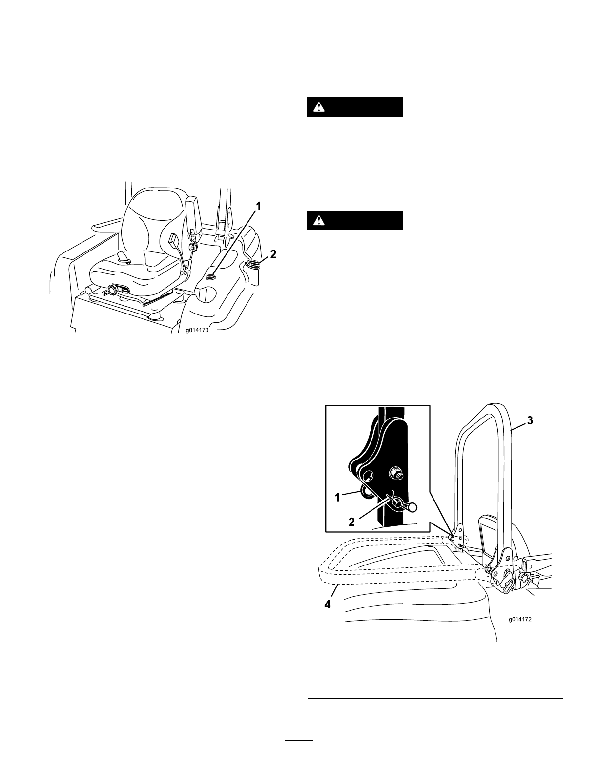
1.Tolowertherollbar,removethehairpincotters,push
therollbarforwardagainstthesprings,andremove
the2pins(Figure9).
Important:Donotopenthefueltankwhen
parkedonahill.Thefuelcouldspillout.
4.Addfueltothefueltank,untilthelevelisevenwith
thebottomofthellerneck.Donotoverllthefuel
tank.
5.Installthefueltankcapandsecure.Wipeupanyfuel
thatmayhavespilled.
Note:Ifpossible,llthefueltankaftereachuse.Thiswill
minimizepossiblebuildupofcondensationinsidethefuel
tank.
UsingtheRolloverProtection System(ROPS)
•KeeptherollbarintheraisedandLOCKEDpositionand
usetheseatbeltwhenoperatingthemachine.
•Becertainthatyoucanreleasetheseatbeltquicklyinthe
eventofanemergency.
•Beawarethereisnorolloverprotectionwhentheroll
barisdown.
•ChecktheareatobemowedandneverfoldtheROPSin
areaswherethereareslopes,drop-offsorwater.
Figure9
1.Pin3.Rollbar,raisedposition
2.Hairpincotter4.Rollbar,loweredposition
2.Lowertherollbartothedownposition(Figure9).
17
Page 18
3.Installthe2pinsandsecurethemwiththehairpin
g026089
cotterpins(Figure9).
Important:Ensurethattheseatissecuredwith
theseatlatch.
4.Toraisetherollbar,removethehairpincotterpinsand
removethe2pins(Figure9).
5.Raisetherollbartotheuprightpositionandinstallthe
2pinsandsecurethemwiththehairpincotterpins
(Figure9).
Important:Alwaysusetheseatbeltwhentherollbar
isintheraisedandlockedposition.Donotusetheseat
beltwhentherollbarisintheloweredposition.
TheSafetyInterlockSystem
CAUTION
Ifthesafetyinterlockswitchesaredisconnectedor
damagedthemachinecouldoperateunexpectedly
andcausepersonalinjury.
•Donottamperwiththeinterlockswitches.
•Checktheoperationoftheinterlockswitches
dailyandreplaceanydamagedswitchesbefore
operatingthemachine.
2.Sittingontheseat,settheparkingbrakeandmovethe
PTOtotheOFFposition.Pressthetractionpedal.Try
startingtheengine;theengineshouldnotstart.
3.Sittingontheseat,settheparkingbrake,movethe
PTOswitchtotheOFFposition,andallowthetraction
pedaltoreturntotheNEUTRALposition.Nowstart
theengine.Whiletheengineisrunning,releasethe
parkingbrake,engagethePTOandriseslightlyfrom
theseat.On2-wheel-drivemachines,theengineshould
stopwithin2seconds.On4-wheel-drivemachines,the
mowerdeckwillshutoff.Theenginecontinuestorun.
4.Withoutanoperatorontheseat,settheparkingbrake,
movethePTOswitchtotheOFFposition,andmove
thetractionpedaltotheNEUTRALposition.Now
starttheengine.Whiletheengineisrunning,pressthe
tractionpedal;theengineshouldstopwithin2seconds.
5.Withoutanoperatorontheseat,releasetheparking
brake,movethePTOswitchtooff,andallowthe
tractionpedaltoreturntotheNEUTRALposition.Try
startingtheengine;theengineshouldnotstart.
SelectingtheSteeringMode
Formaximumtrimmingandminimumturfdamage,operate
themachineinthe4-wheel-steeringmode.However,when
transportingthemachineonroadsortrails,switchthe
machineinto2-wheel-steeringmode.
UnderstandingtheSafetyInterlock
System
Thesafetyinterlocksystemisdesignedtopreventtheengine
fromstartingunless:
•Youaresittingontheseatortheparkingbrakeisset.
•Thepowertakeoff(PTO)isdisengaged.
•ThetractionpedalisintheNEUTRALposition
•Theenginetemperatureisbelowthemaximumoperating
temperature.
Thesafetyinterlocksystemalsoisdesignedtoshutoffthe
enginewhenthetractionpedalmovesfromtheNEUTRAL
positionwiththeparkingbrakeset.Ifyourisefromtheseat
whenthePTOisengagedthereisa1-seconddelayandthen
theenginestops.
TestingtheSafetyInterlockSystem
ServiceInterval:Beforeeachuseordaily
Testthesafetyinterlocksystembeforeyouusethemachine
eachtime.Ifthesafetysystemdoesnotoperateasdescribed
below,haveanAuthorizedServiceDealerrepairthesafety
systemimmediately.
1.Sittingontheseat,settheparkingbrakeandmovethe
PTOtotheONposition.Trystartingtheengine;the
engineshouldnotstart.
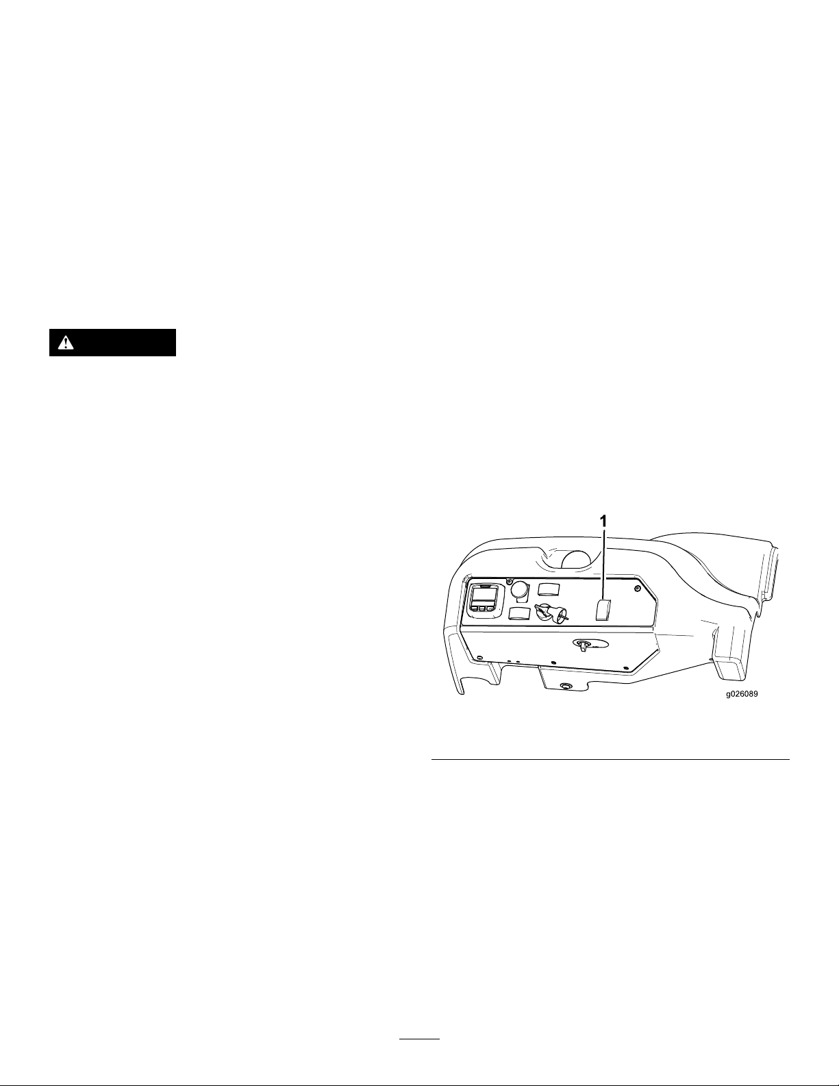
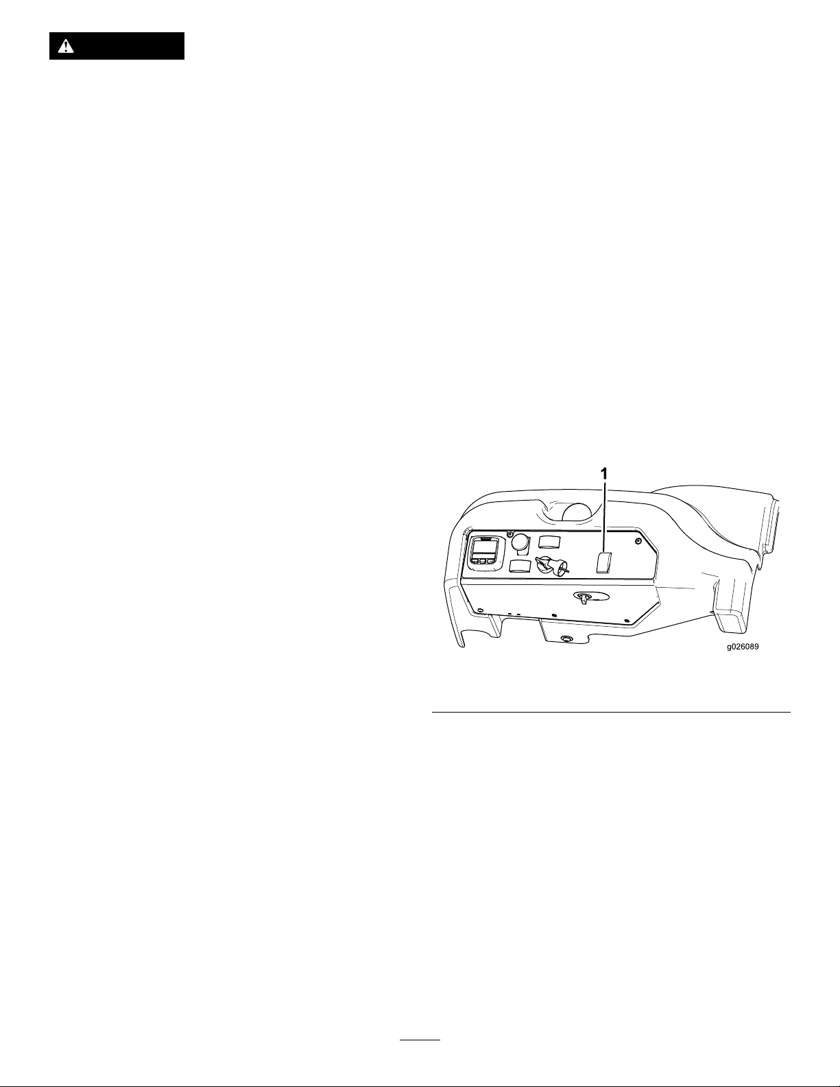
Figure10
1.Steeringselectorswitch
Switchingfrom4-WheelSteeringto
2-WheelSteering
Pressthesteeringselectorswitch(Figure10)totheforward
position.Whenthewheelsarenotalignedintheforward
position,thegreenlightashesandthemachineremains
inthe4-wheel-steeringmodeuntilthe4tirespointstraight
ahead.Turnthesteeringwheelslowlytostraightenoutthe
wheelsuntilthegreenlightstopsashingandremainson.
Whentheswitchlightissolidgreen,themachineisin2-wheel
steering.
Note:Ifyouturnthesteeringwheeltoobriskly,steering
misalignmentmayoccur.
18
Page 19
Switchingfrom2-WheelSteeringto
4-WheelSteering
Pressthesteeringselectorswitch(Figure10)totherearward
position.Whenthefrontwheelsarenotalignedinthe
forwardposition,thegreenlightashesandthemachine
remainsin2-wheel-steeringmodeuntilthe4tirespoint
straightahead.Turnthesteeringwheelslowlytostraighten
outthewheelsuntilthegreenlightstopsashingandremains
off.Whentheswitchlightiscontinuouslyoff,themachineis
inthe4-wheel-steeringmode.
Note:Ifyouturnthesteeringwheeltoobriskly,steering
misalignmentmayoccur.
Note:Ifthesteeringsystemismisalignedafterrepeated
2-wheel-steeringto4-wheel-steeringengagements,referto
CorrectingSteeringMisalignment(page36).
PositioningtheStandardSeat
ChangingtheSeatSuspension
Youcanadjusttheseattoprovideasmoothandcomfortable
ride.Positiontheseatwhereyouaremostcomfortable.
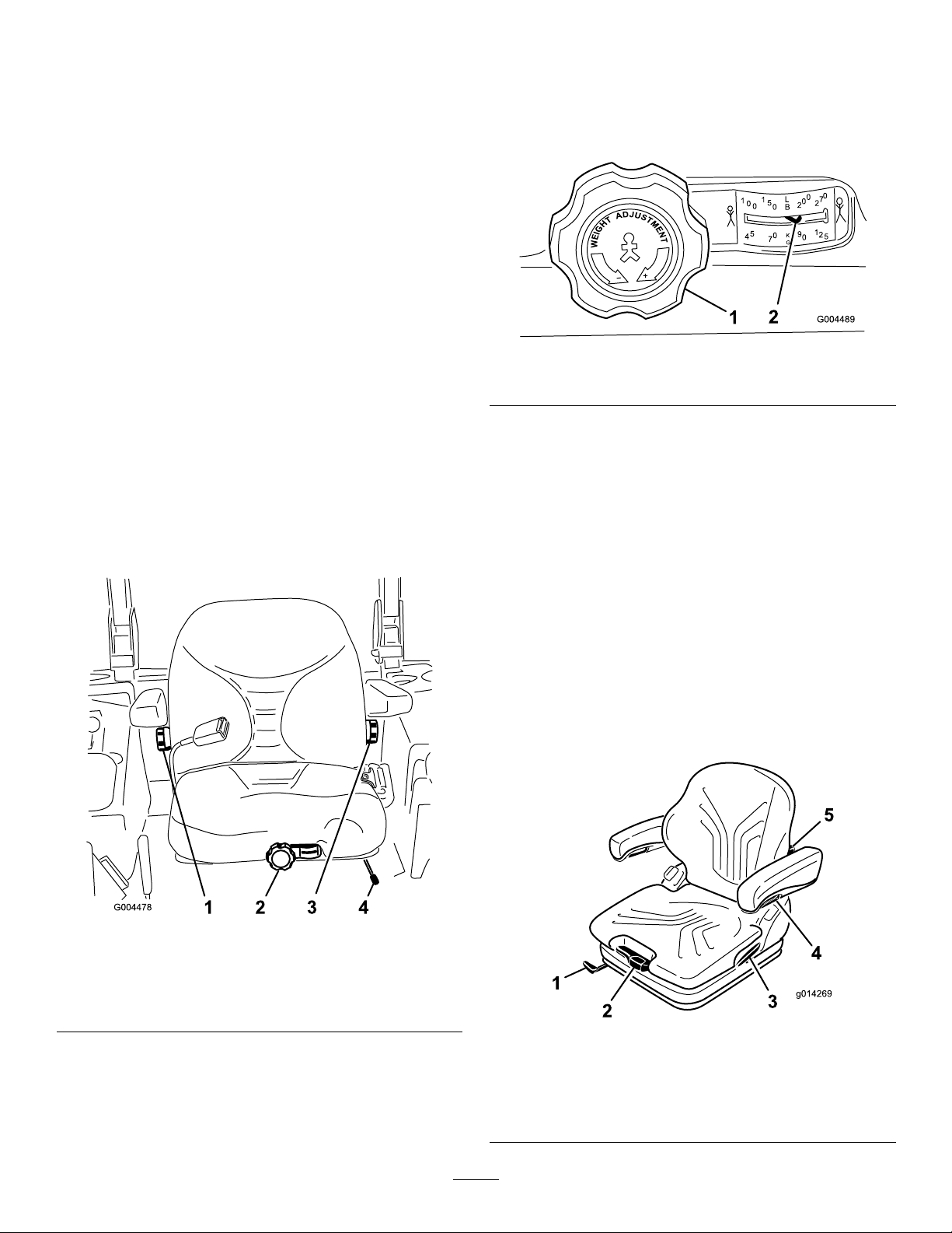
Withoutsittingontheseat,turntheknobinfronteither
directiontoprovidethebestcomfort(Figure12).
Figure12
1.Seat-suspensionknob2.Operator-weightsetting
ChangingtheSeatPosition
Youcanmovetheseatforwardandbackward.Positionthe
seatwhereyouhavethebestcontrolofthemachineandare
mostcomfortable.
1.Movetheleversidewaystounlocktheseat(Figure11).
ChangingtheBackPosition
Youcanadjustthebackoftheseattoprovideacomfortable
ride.Positionthebackoftheseatwhereitismost
comfortable.
Toadjustit,turntheknob,undertheright-sidearmrest,in
eitherdirectiontoprovidethebestcomfort(Figure11).
ChangingtheLumbarSupport
Youcanadjustthebackoftheseattoprovideacustomized
lumbarsupportforyourlowerback.
Toadjustit,turntheknob,undertheleft-sidearmrest,in
eitherdirectiontoprovidethebestcomfort(Figure11).
PositioningtheDeluxeSeat
Figure11
1.Backrestknob3.Lumbar-support
adjustmentknob
2.Seat-suspensionknob4.Seat-positionadjustment
lever
2.Slidetheseattothedesiredpositionandreleaselever
tolockitinposition.
3.Verifythattheseathaslockedintoplacebyattempting
tomoveitbackandforth.
Figure13
1.Fore/Aft-adjustmentlever
2.Weight-adjustmentlever5.Lumbar-supportadjusting
3.Backrest-lockinglever
19
4.Armrest-adjustmentknob
knob
Page 20
AdjustingtheWeightSetting
Youcanadjusttheseattoprovideasmoothandcomfortable
ride.
Important:Toadjusttheseatforthedriver’sweight,
thedrivermustbeseatedandtheignitionkeymustbe
intheONposition.
Toadjusttheheightofthearmrests,separatetheroundcap
(Figure13)fromthecover,loosenthehexagonnut(13mm)
behinditandadjustthearmreststothedesiredpositionand
tightenthenut.Theninstallthecapontothenut.
Note:Donotinstallthearmrestinthelowestpositionasthe
seat-beltrollermightnotfunctionproperly.
Adjusttheseatforyourbodyweightbypullingorpressing
theweight-adjustmentlever(Figure13).
Theseatisadjustedcorrectlywhenthearrowisinthemiddle
clearareaoftheviewingwindow .
Withinthisviewingarea,youcanadjusttheseattoaminimum
springmovement.
Whentheminimum/maximumweightadjustmenthasbeen
reached,youcanhearitreachingtheupper-orlower-endstop.
Important:Topreventinjurytotheoperatorand/or
damagetothemachine,checkandadjusttheweight
settingbeforeoperatingthemachine.
Note:Toavoidcompressordamageduringweight
adjustment,donotoperatethecompressorforlongerthan
1minute.
ChangingtheSeatPosition
Theseatcanmoveforwardandbackward.Positiontheseat
whereyouhavethebestcontrolofthemachineandaremost
comfortable.
1.Liftthelevertounlocktheseat(Figure13).
2.Slidetheseattothedesiredpositionandreleaselever
tolockitinposition.
3.Verifythattheseathaslockedintoplacebyattempting
tomoveitbackandforth.
Note:Donotoperatethelockingleverwhile
operatingthemachine.
ChangingtheLumbarSupport
ChangingtheArmrestAngle
Youcanadjusttheangleofthearmrestsforoperatorcomfort.
Toadjusttheangleofthearmrests,turntheadjustmentknob
(Figure13).
Turningtheknobtotheoutside(+)liftsthefrontpartofthe
armrest;turningtheknobtoinside(-)lowersit.
ChangingtheBackrestPosition
Youcanadjustthebackoftheseattoprovideamore
comfortableride.Positionthebackoftheseatwhereitis
mostcomfortable.
Pullupthelockinglevertoreleasethebackrestcatch(Figure
13).Whenreleasingthebackrestcatch,donotapplyloadto
thebackrestbypressingagainstit.
Byexertingpressureonoroffthefrontorrearoftheseatit
canbemovedtothedesiredposition.Releasethelocking
levertolockthebackrest.
Note:Thebackrestshouldnotbeabletomoveintoanother
positionafterithasbeenlocked.
Raising/LoweringtheSeat
Toaccessthehydraulicandothersystemsundertheseat,you
needtounlatchtheseatandswingitforward.
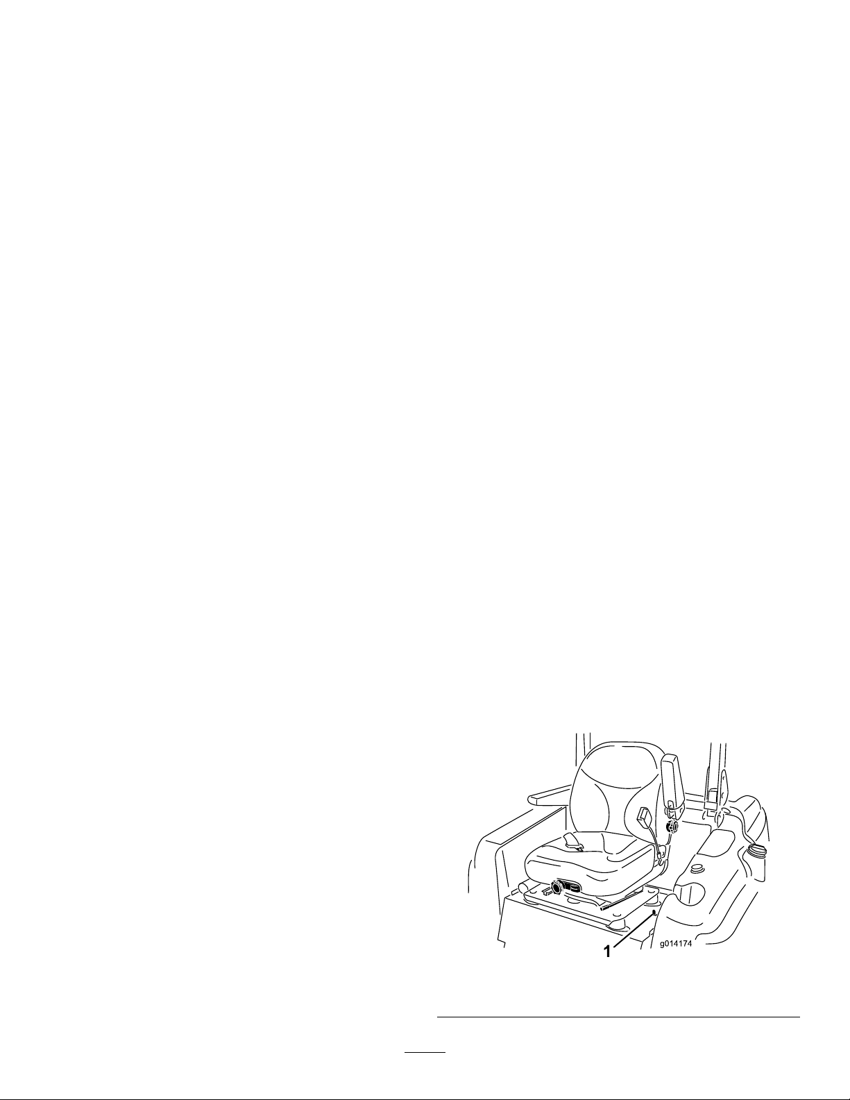
1.Movetheseatlatchlocatedontheleftsideofthe
seat(Figure14)rearwardtounlatchtheseat,andpull
forwardonthetopoftheseat.
Thelumbarsupportincreasesboththeseatingcomfortand
theperformanceofthedriver.
Thebackoftheseatcanbeadjustedtoprovideacustomized
lumbarsupportforyourlowerback.
Byturningtheadjustmentknobupwards,thecurvaturein
theupperpartofthebackrestcushioncanbeadjusted.By
turningtheknobdownwards,thecurvatureinthelowerpart
ofthebackrestcushioncanbeadjusted(Figure13).
0=Nocurvature
1=Maximumcurvatureatthetop
2=Maximumcurvatureatthebottom
AdjustingtheArmrests
Youcanadjusttheheightofthearmrestsandfoldthemback.
Figure14
1.Seatlatch
20
Page 21
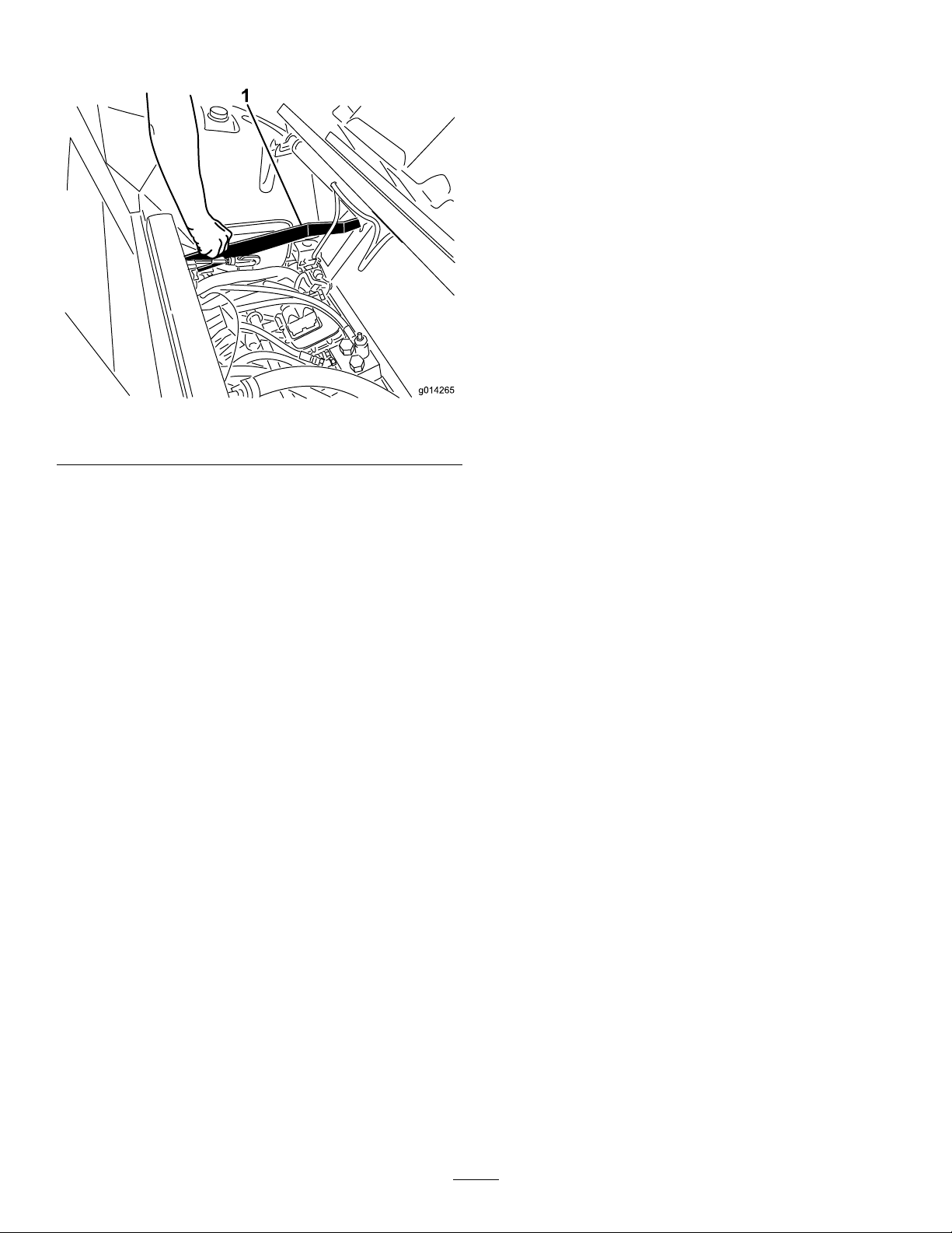
2.Tolowertheseat,pullupontheseat-latchreleasebar
andlowertheseatintotheLOCKEDposition.
Figure15
1.Seat-latchreleasebar
DuringOperation
DuringOperationSafety
GeneralSafety
•Theowner/usercanpreventandisresponsiblefor
accidentsthatmaycauseinjuriestohimself/herselfand
othersandfordamagetoproperty.
•Wearappropriateclothing,includingeyeprotection;
slip-resistant,substantialfootwear;andhearing
protection.Wearingsafetyshoesandlongpantsis
advisableandrequiredbysomelocalordinancesand
insuranceregulations.Tiebacklonghair,secureloose
clothing,anddonotwearjewelry.
•EnsurethatalldrivesareintheNEUTRALposition,the
parkingbrakeisengaged,andyouareintheoperating
positionbeforeyoustarttheengine.
•Keepallbodyparts,includinghandsandfeet,awayfrom
allmovingparts.
•Donotoperatethemachinewhileill,tired,orunderthe
inuenceofalcoholordrugs.
•Keepthedirectionofthemowerdischargeawayfrom
peopleandpets.
•Donotmowinreverseunlessitisabsolutelynecessary.If
youmustmowinreverse,lookbehindanddownforsmall
childrenbeforeandwhilemovingthemachineinreverse.
Stayalertandstopthemachineifachildentersthearea.
•Useextremecarewhenapproachingblindcorners,
shrubs,trees,orotherobjectsthatmayblockyourview.
•Donotmowneardrop-offs,ditches,orembankments.
Themachinecouldsuddenlyrolloverifawheelgoes
overtheedgeoriftheedgecavesin.
•Nevercarrypassengersonthemachine.
•Operatethemachineonlyingoodvisibilityand
appropriateweatherconditions.Donotoperatethe
machinewhenthereistheriskoflighting.
•Donotmowonwetgrass.Reducedtractioncouldcause
themachinetoslide.
•Neverraisethemowerdeckwiththebladesrunning.
•Stopthemachineandinspectthebladesafterstrikingan
objectorifthereisanabnormalvibrationinthemachine.
Makeallnecessaryrepairsbeforeresumingoperation.
•Stopthebladeswheneveryouarenotmowing,especially
whilecrossinglooseterrainsuchasgravel.
•Slowdownandusecautionwhenmakingturnsand
crossingroadsandsidewalkswiththemachine.Always
yieldtheright-of-way.
•Turnontheashingwarninglightsonthemachine
wheneveryoutravelonapublicroad,exceptwheresuch
useisprohibitedbylaw.
•Disengagethedrivetotheattachmentandshutoffthe
enginebeforeaddingfuelandadjustingtheheightofcut.
•Reducethethrottlesettingbeforestoppingtheengine
and,iftheenginehasafuel-shutoffvalve,shutoffthe
fuelwhenyouhavenishedoperatingthemachine.
•Neverrunanengineinanareawhereexhaustgasesare
enclosed.
•Neverleavearunningengineunattended.
•Beforeleavingtheoperatingposition,dothefollowing:
–Stopthemachineonlevelground.
–Disengagethepowertake-offandlowerthe
attachments.
–Settheparkingbrake.
–Shutofftheengineandremovethekey .
–Waitforallmovingpartstostop.
•Donotchangethegovernorsettingsonoroverspeed
theengine.Operatingtheengineatexcessivespeedmay
increasethepotentialforpersonalinjury.
•Donotusethemachineasatowingvehicle.
•UseaccessoriesandattachmentsapprovedbyTheToro®
Companyonly.
RolloverProtectionSystem(ROPS)
Safety
•DonotremovetheROPSfromthemachine.
•Ensurethattheseatbeltisattachedandthatyoucan
releaseitquicklyintheeventofanemergency.
•AlwayswearyourseatbeltwhentheROPSisup.
•Checkcarefullyforoverheadclearances,suchasbranches,
doorways,andelectricalwires,beforedrivingthemachine
underthem.Donotcontactthem.
21
Page 22
•KeeptheROPSinsafeoperatingconditionbythoroughly
G009027
1
2
g026090
4
inspectingitperiodicallyfordamageandkeepingallthe
mountingfastenerstight.
•ReplaceadamagedROPS.Donotrepairorreviseit.
•AnyalterationstoaROPSmustbeapprovedbyThe
Toro®Company.
StartingandStoppingthe Engine
StartingtheEngine
1.Raisetherollbarupandlockitintoplace,sitonthe
seat,andfastentheseatbelt.
SlopeSafety
•Slowdownthemachineanduseextracareonhillsides.
Travelintherecommendeddirectiononhillsides.Turf
conditionscanaffectthestabilityofthemachine.
•Avoidstarting,stopping,orturningthemachineona
slope.Ifthetireslosetraction,disengagetheblade(s)and
proceedslowlystraightdowntheslope.
•Donotturnthemachinesharply .Usecarewhenreversing
themachine.
•Whenoperatingthemachineonaslope,alwayskeepall
cuttingunitslowered.
•Avoidturningthemachineonslopes.Ifyoumustturn,
turnslowlyandgraduallydownhill,ifpossible.
•Useextracarewhileoperatingthemachinewith
attachments;theycanaffectthestabilityofthemachine.
ThinkSafetyFirst
Pleasereadallsafetyinstructionsandsymbolsinthesafety
section.Knowingthisinformationcouldhelpyouor
bystandersavoidinjury.
2.MakesurethatthetractionpedalisintheNEUTRAL
position.
3.Settheparkingbrake.
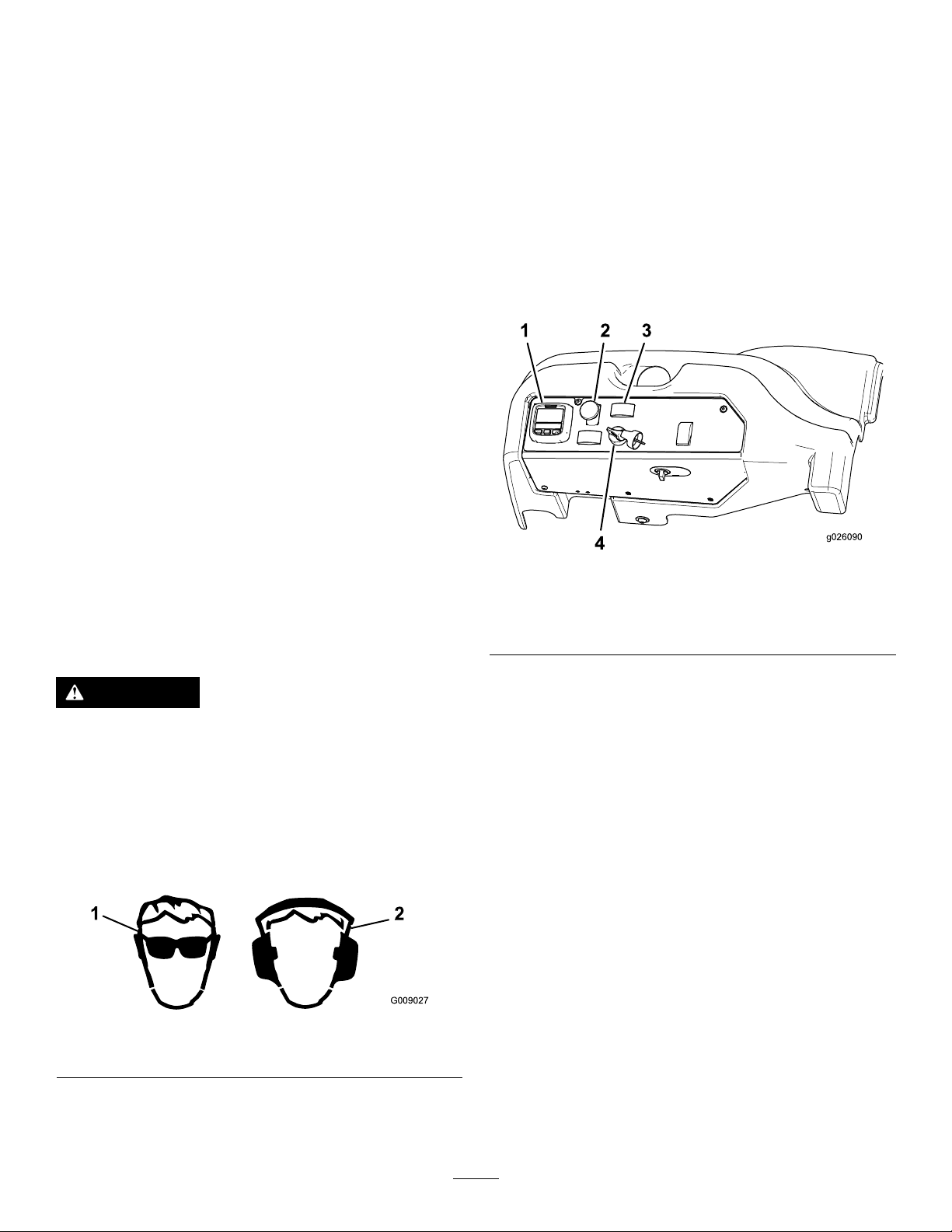
4.MovethePTO(powertake-off)switchtotheOFF
position(Figure17).
Figure17
1.InfoCenter
2.Powertake-offswitch
(PTO)
3.Engine-speedswitch
4.Ignitionswitch
CAUTION
Thismachineproducessoundlevelsinexcessof
85dBAattheoperator’searandcancausehearing
lossthroughextendedperiodsofexposure.
Wearhearingprotectionwhenoperatingthis
machine.
Theuseofprotectiveequipmentforeyes,ears,hands,feet,
andheadisrecommended.
Figure16
1.Weareyeprotection.2.Wearhearingprotection.
5.TurntheignitionkeyclockwisetotheRUNposition.
TheInfoCenterglow-plugiconturnsonin6seconds.
6.AftertheInfoCenterglow-plugicongoesout,turnthe
keytotheSTARTposition.Whentheenginestarts,
releasethekey.
Important:Usestartingcyclesofnomorethan
15secondsperminutetoavoidoverheatingthe
startermotor.
Note:Additionalstartingcyclesmayberequired
whenstartingtheengineforthersttimeafterthefuel
systemhasbeencompletelydrained.
Important:Whenyoustarttheenginefortherst
time,orafteranengineoilchangeoranoverhaul
oftheengine,thetransmission,orawheelmotor,
operatethemachinewiththeengine-speedswitch
intheSlowpositioninboththeforwardandreverse
directionsfor1to2minutes.Alsooperatethedeck
liftswitchandthePTOswitchtoensureproper
operationofalltheparts.Thenshuttheengineoff
andchecktheuidlevelsandcheckforoilleaks,
looseparts,andanyothernoticeablemalfunctions.
22
Page 23
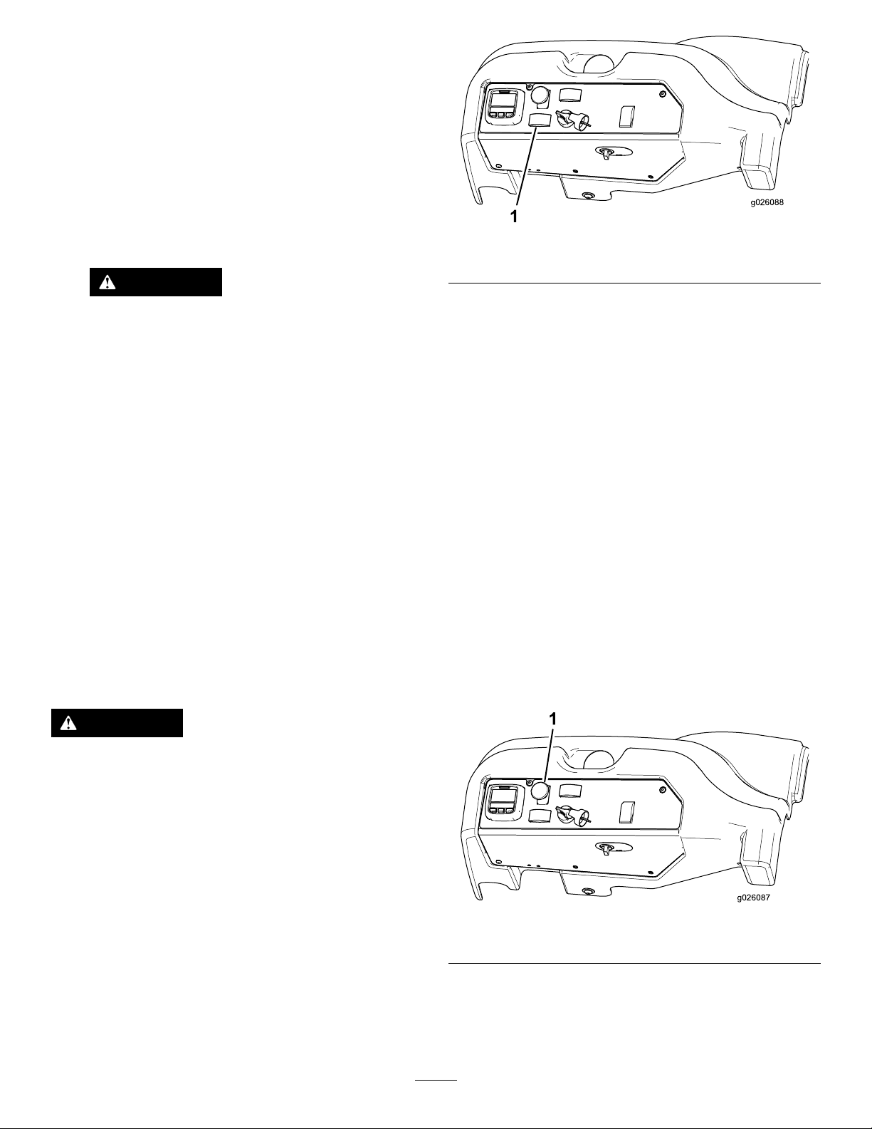
StoppingtheEngine
g026088
g026087
1.DisengagethePTO,makesurethatthetractionpedal
isintheNEUTRALposition,settheparkingbrake,and
movetheenginespeedswitchtotheidleposition.
2.Lettheengineidlefor60seconds.
3.TurntheignitionkeytotheOFFposition.
4.Removethekeybeforetransportingorstoringmachine.
Important:Removethekey;otherwise,thefuel
pumporaccessoriesmayrunandcausethe
batterytolosecharge.
CAUTION
Childrenorbystandersmaybeinjuredifthey
moveorattempttooperatethemachinewhile
itisunattended.
Alwaysremovetheignitionkeyandsetthe
parkingbrakewhenleavingthemachine
unattended,evenifjustforafewminutes.
DrivingtheMachine
Thethrottlecontrolregulatestheenginespeedasmeasured
inrpm(revolutionsperminute).Placethethrottlecontrolin
theFastpositionforbestperformance.Alwaysoperateinthe
Fastthrottlepositionwhenmowing.
Figure18
1.Deckliftswitch
•Tolowerthemowerdeck,pushtheswitchforward.
•Toraisethemoverdeck,pushtheswitchrearward.
Important:Donotcontinuetoholdtheswitchback
afterthemowerhasfullyraised.Doingsowilldamage
thehydraulicsystem.
Note:Tolockthemowerdeckinaraisedposition,raise
thedeckpastthe15cm(6inch)position,removetheheight
ofcutstoppin,andplacethepininthe15cm(6inch)
height-of-cutposition.
EngagingthePowerTakeoff(PTO)
Thepower-takeoff(PTO)switchstartsandstopsthemower
bladesandsomepoweredattachments.
StoppingtheMachine
Tostopthemachine,releasethetractionpedaltothe
NEUTRALposition.
Settheparkingbrakewheneveryouleavethemachine.
Remembertoremovethekeyfromtheignitionswitch.
CAUTION
Childrenorbystandersmaybeinjuredifthey
moveorattempttooperatethemachinewhileitis
unattended.
Alwaysremovetheignitionkeyandsettheparking
brakewhenleavingthemachineunattended,even
ifjustforafewminutes.
OperatingtheMower
RaisingandLoweringtheMower
Thedeckliftswitchraisesandlowersthemowerdeck(Figure
18).Theenginemustberunningforyoutousethisswitch.
1.Iftheengineiscold,allowtheenginetowarmup5to
10minutesbeforeengagingthePTO .
2.Whileseatedintheseat,makesurethatthetraction
pedalisintheNeutralpositionandtheengineisatfull
throttle.
3.PulluponthePTOswitchtoengageit(Figure19).
Figure19
1.PTOswitch
DisengagingthePTO
TodisengagethePTO ,pushtheswitchtotheOFFposition.
23
Page 24

OperatingTips
UsingtheFastThrottleSetting
Tomaintainenoughpowerforthemachineanddeckwhile
mowing,operatetheengineatthefastthrottlepositionand
adjustyourgroundspeedforconditions.
SelectingtheGroundSpeed
Toimprovecutquality,useaslowergroundspeed.Decrease
thegroundspeedastheloadonthecuttingbladesincreases,
andincreasegroundspeedasloadonthebladesdecreases.
AlternatingMowingDirection
Alternatemowingdirectiontoavoidmakingrutsintheturf
overtime.Thisalsohelpsdisperseclippingswhichenhances
decompositionandfertilization.
AvoidingCuttingTooLow
Ifthecuttingwidthofthemoweriswiderthanthemower
youpreviouslyused,raisethecuttingheighttoensurethat
uneventurfisnotcuttooshort.
SelectingtheProperHeightofCutto
SuitConditions
Removeapproximately25mm(1inch)ornomorethan1/3
ofthegrassbladewhencutting.Inexceptionallylushand
densegrass,youmayhavetoslowdowntheforwardspeed
and/orraisetheheightofcuttothenexthighersetting.
MaintainingtheBlades
Maintainsharpbladesthroughoutthecuttingseasonbecause
sharpbladescutcleanlywithouttearingorshreddingthe
grassblades.Tearingandshreddingturnsgrassbrownat
theedges,whichslowsgrowthandincreasesthechanceof
disease.Checkthebladesdailyforsharpnessandforany
wearordamage.Sharpenthebladesasnecessary.Ifabladeis
damagedorworn,replaceitimmediatelywithagenuineToro
replacementblade.RefertoServicingtheCuttingBladesin
themower-deckmanual.
AfterOperation
AfterOperationSafety
GeneralSafety
•Cleangrassanddebrisfromthecuttingunits,drives,
mufers,andenginetohelppreventres.Cleanupoil
orfuelspills.
•Shutoffthefuelwhilestoringortransportingthe
machine,ifapplicable.
•Disengagethedrivetotheattachmentwheneveryouare
transportingornotusingthemachine.
•Allowtheenginetocoolbeforestoringthemachinein
anyenclosure.
•Neverstorethemachineorfuelcontainerwherethereis
anopename,spark,orpilotlight,suchasonawater
heateroronotherappliances.
Important:Ifcuttingmorethan1/3ofthegrassblade
off,orinsparselonggrassordryconditions,theuse
ofatsailbladesisrecommendedtoreduceair-borne
chaff,debris,andunnecessarystrainondeck-drive
components.
CuttingLongGrass
Ifthegrassiseverallowedtogrowslightlylongerthan
normal,orifitcontainsahighdegreeofmoisture,raisethe
cuttingheighthigherthanusualandcutthegrassatthis
setting.Thencutthegrassagainusingthelower,normal
setting.
KeepingtheMowerClean
Cleanclippingsanddirtfromtheundersideofthemower
aftereachuse.Ifgrassanddirtbuildupinsidethemower,
cuttingqualitywilleventuallybecomeunsatisfactory.
Toreducetheriskofre,keeptheengine,mufer,battery
compartment,parkingbrake,cuttingunits,andfuelstorage
compartmentfreeofgrass,leaves,orexcessivegrease.Clean
upanyspilledoilorfuel.
PushingtheMachinebyHand
Ifthemachinerunsoutoffuelorstallsforanotherreason,
youmayneedtopushit.Todoso,yourstneedtoopen
bothofthehydraulicbypassvalves.
Important:Alwayspushthemachinebyhandand
neveroveralongdistance.Nevertowthemachine,
becausehydraulicdamagemayoccur.
PushingtheMachine
1.Disengagethepowertake-off(PTO),turntheignition
keytotheOFFpositionandapplytheparkingbrake.
2.Removethekeyfromtheignitionswitch.
3.Lifttheseat.
4.Rotateeachbypassvalvecounterclockwise1turn
(Figure20).
Bothbypassvalvesmustbeopen.Thisallowsthe
hydraulicuidtobypassthepump,enablingthewheels
toturn.
24
Page 25
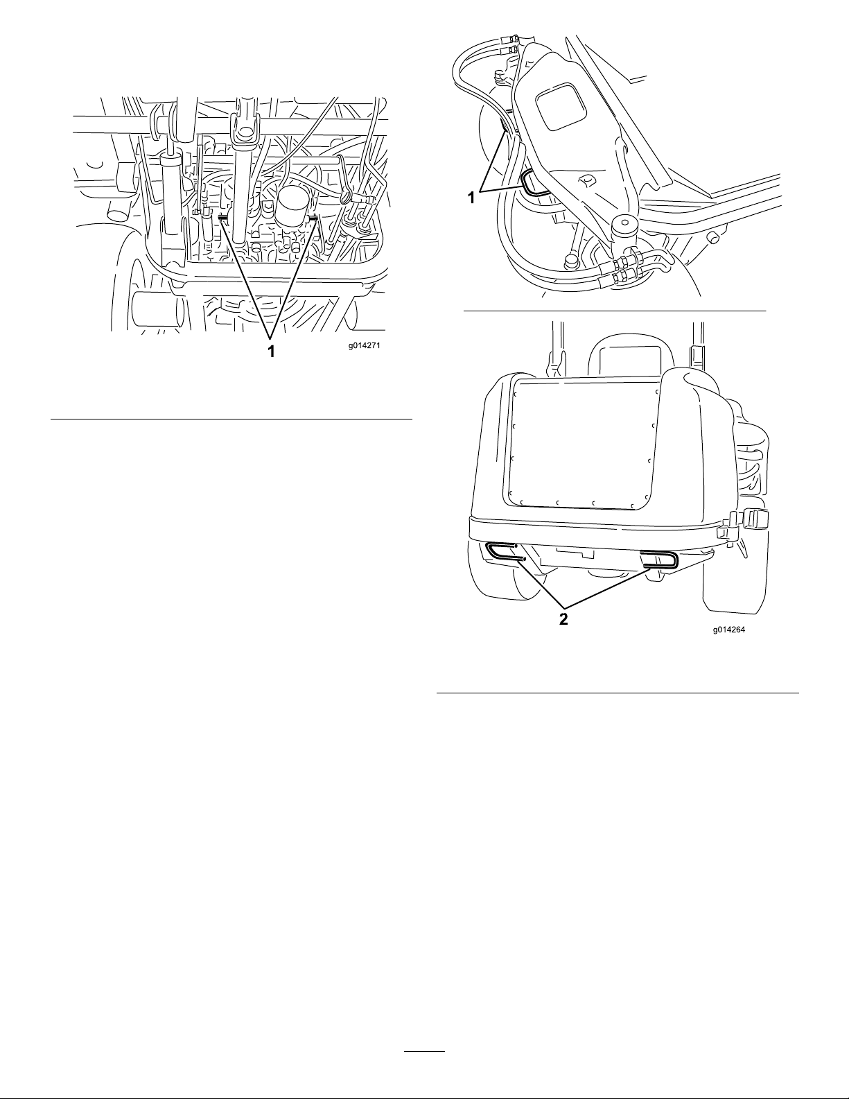
Important:Donotrotatethebypassvalvesmore
than1turn.Thispreventsthevalvesfromcoming
outofthebodyandcausinguidtorunout.
Figure20
1.Bypassvalves
5.Releasetheparkingbrakebeforepushingthemachine.
ChangingtoMachineOperation
Rotateeachbypassvalveclockwise1turnandhandtighten
them.Torquethemtoapproximately8N∙m(71in-lb);refer
toFigure20.
Note:Themachinedoesnotdriveunlessthebypassvalves
aretightened.Donotovertightenthebypassvalves.
HaulingtheMachine
•Usecarewhenloadingorunloadingthemachineintoa
traileroratruck.
•Usefull-widthrampsforloadingthemachineintoa
traileroratruck.
•Tiethemachinedownsecurelyusingstraps,chains,cable,
orropes.Bothfrontandrearstrapsshouldbedirected
downandoutwardfromthemachine.
Figure21
1.Fronttie-down2.Reartie-downs
25
Page 26

Maintenance
Note:Determinetheleftandrightsidesofthemachinefromthenormaloperatingposition.
RecommendedMaintenanceSchedule(s)
MaintenanceService
Interval
Aftertherst10hours
Aftertherst200hours
Beforeeachuseordaily
Every50hours
Every100hours
Every200hours
Every250hours
MaintenanceProcedure
•Checkthetensionofthealternatorbelt.
•T orquethewheellugnuts.
•Changethehydraulicuidandlter.
•T estthesafetysystem.
•Greasethebearingandbushinggreasettings(ifoperatingconditionsaredirty
anddusty).
•Checktheair-cleanerindicator
•Checktheengine-oillevel.
•Drainwaterorothercontaminantsfromthewaterseparator.
•Checktheleveloftheenginecoolant.
•Cleantheradiatorwithcompressedair(donotusewater).
•Checkthelevelofthehydraulicuid.
•Greasethebearingandbushinggreasettings.
•Checktheconnectionsofthebatterycable.
•Checkthetirepressure.
•Checkthetensionofthealternatorbelt.
•Inspectthehosesandsealsofthecoolingsystem.Replacethemiftheyarecracked
ortorn.
•T orquethewheellugnuts.
•Changetheengineoilandlter.
•Servicetheaircleaner(earlieriftheaircleanerindicatorshowsred,andmore
frequentlyinextremelydirtyordustyconditions).
Every400hours
Every800hours
Every1,500hours
Every6,000hours
Every2years
•Replacethefuel-ltercanister.
•Replacetheenginefuellter.
•Checkthefuellinesandconnections.
•Changethehydraulicuidandlter.
•Inspecttheenginevalveclearance;refertoyourengineoperator'smanual.
•Replacethemovinghoses.
•ReplacetheDOC
•Flushandreplacetheenginecoolant.
Important:Refertoyourengineoperator'smanualforadditionalmaintenanceprocedures.Adetailedservice
manualisalsoavailableforpurchasefromyourAuthorizedToroDistributor.
Note:Toobtainanelectricalschematicorahydraulicschematicforyourmachine,visitwww.Toro.com.
26
Page 27
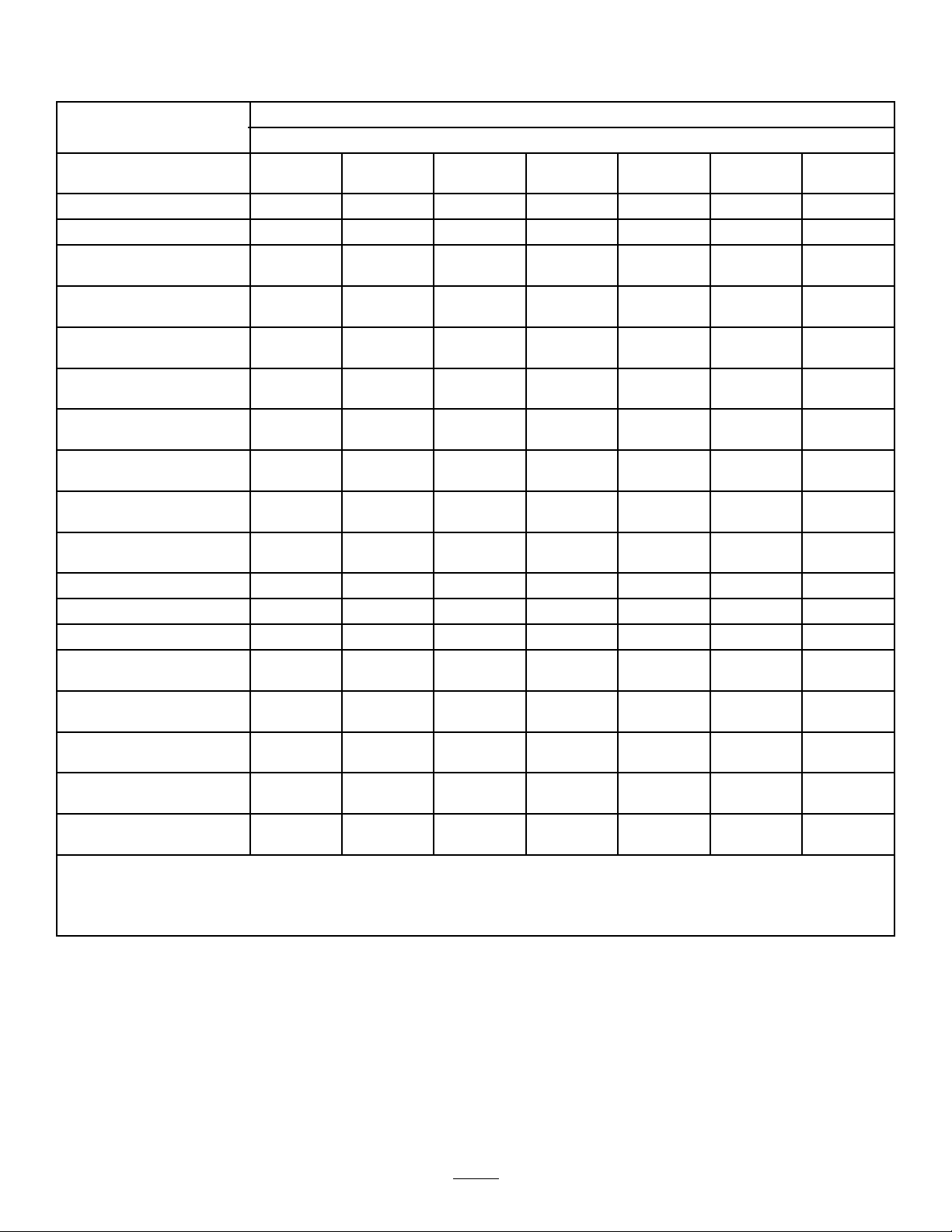
DailyMaintenanceChecklist
Duplicatethispageforroutineuse.
Fortheweekof:
MaintenanceCheckItem
Checkthesafety-interlock
operation.
Checkthebrakeoperation.
Checktheengine-oillevel.
Checkthe
cooling-system-uidlevel.
Drainthewater/fuel
separator.
Checktheairlter,dustcup,
andburpvalve.
Checkforunusualengine
2
noises.
Checktheradiatorand
screenfordebris
Checkforunusualoperating
noises.
Checkthehydraulic-systemoillevel.
Checkthehydraulichoses
fordamage.
Checkforuidleaks.
Checkthefuellevel.
Checkthetirepressure.
Checktheinstrument
operation.
Checktheheight-of-cut
adjustment.
Lubricateallthegrease
2
ttings.
Touchupanydamaged
paint.
Checktheair-lterrestriction
indicator
1
Checktheglowplugandinjectornozzlesifstartingishard,thereisexcesssmoke,orroughrunningisnoted.
2
Immediatelyaftereverywashing,regardlessoftheintervallisted.
3
3
Ifindicatorshowsred
MondayTuesdayWednesdayThursdayFriday
SaturdaySunday
27
Page 28
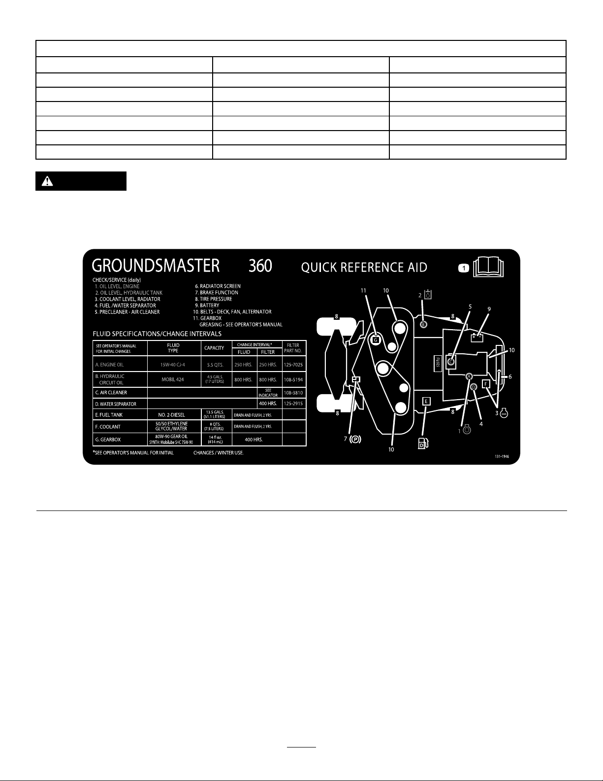
NotationforAreasofConcern
Inspectionperformedby:
ItemDate
Information
CAUTION
Ifyouleavethekeyintheignitionswitch,someonecouldaccidentlystarttheengineandseriouslyinjure
youorotherbystanders.
Removethekeyfromtheignitionbeforeyoudoanymaintenance.
ServiceIntervalChart
Premaintenance
Procedures
Pre-MaintenanceSafety
•Keepallpartsofthemachineingoodworkingcondition
andallhardwaretightened,especiallyblade-attachment
hardware.Replaceallwornordamageddecals.
•Neverallowuntrainedpersonneltoservicethemachine.
•Beforeadjusting,cleaning,orrepairingthemachine,do
thefollowing:
1.Movethemachinetolevelground.
2.Disengagethedrives.
Figure22
3.Lowerthecuttingunits.
4.MovethetractionpedaltotheNEUTRALposition.
5.Engagetheparkingbrake.
6.MovethethrottleswitchtotheLOW-IDLEposition.
7.Shutofftheengineandremovethekey.
8.Waitforallmovingpartstostop.
•Wheneveryouparkorstorethemachine,orleaveit
unattended,lowerthecuttingunitsunlessyouusea
positivemechanicallock.
•Ifpossible,donotperformmaintenanceonthemachine
whiletheengineisrunning.Ifyoumustruntheengineto
performmaintenanceonthemachine,keepyourhands,
feet,otherbodyparts,andclothingawayfromallmoving
28
Page 29
parts,themower-dischargearea,andtheundersideof
1
G015806
themowers.
•Donottouchpartsofthemachineoranattachment
thatmaybehotfromoperation.Allowthepartstocool
beforeattemptingtomaintain,adjust,orservicethem.
•Usejackstandstosupportthemachineand/orits
componentswhenrequired.
•Carefullyreleasepressurefromcomponentswithstored
energy.
•Ifyourmachinerequiresmajorrepairsorifyoudesire
assistance,contactanAuthorizedToroDistributor.
•UseonlygenuineTororeplacementpartsandaccessories.
Replacementpartsandaccessoriesmadebyother
manufacturerscouldbedangerous,andsuchusecould
voidtheproductwarranty.
PreparingtheMachinefor Maintenance
1.EnsurethatthePTOisdisengaged.
2.Parkthemachineonalevelsurface.
3.Settheparkingbrake.
4.Lowerthemowerdeck(s)ifnecessary.
5.Shutofftheengineandwaitforallmovingpartsto
stop.
6.TurntheignitionkeytotheSTOPpositionandremove
it.
7.Allowmachinecomponentstocoolbeforeperforming
maintenance.
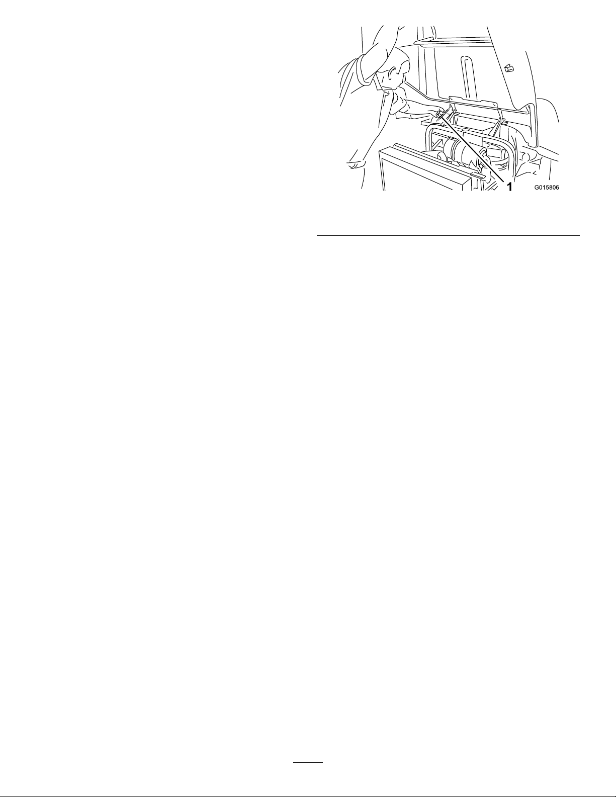
UsingtheHoodPropRod
Figure23
1.Proprod
1.Releasethehoodlatches.
2.Raisethehoodhighenoughtopositiontheproprod
behindtheframetube(Figure23).
3.Lowerthehooduntiltherodisinfrontofandresting
againsttheframetube.
4.Tolowerthehood,raisethehooduntiltheproprod
canberaisedabovetheframetube,thenlowerthe
hood.
5.Securethehoodlatches.
29
Page 30
Lubrication
G026734
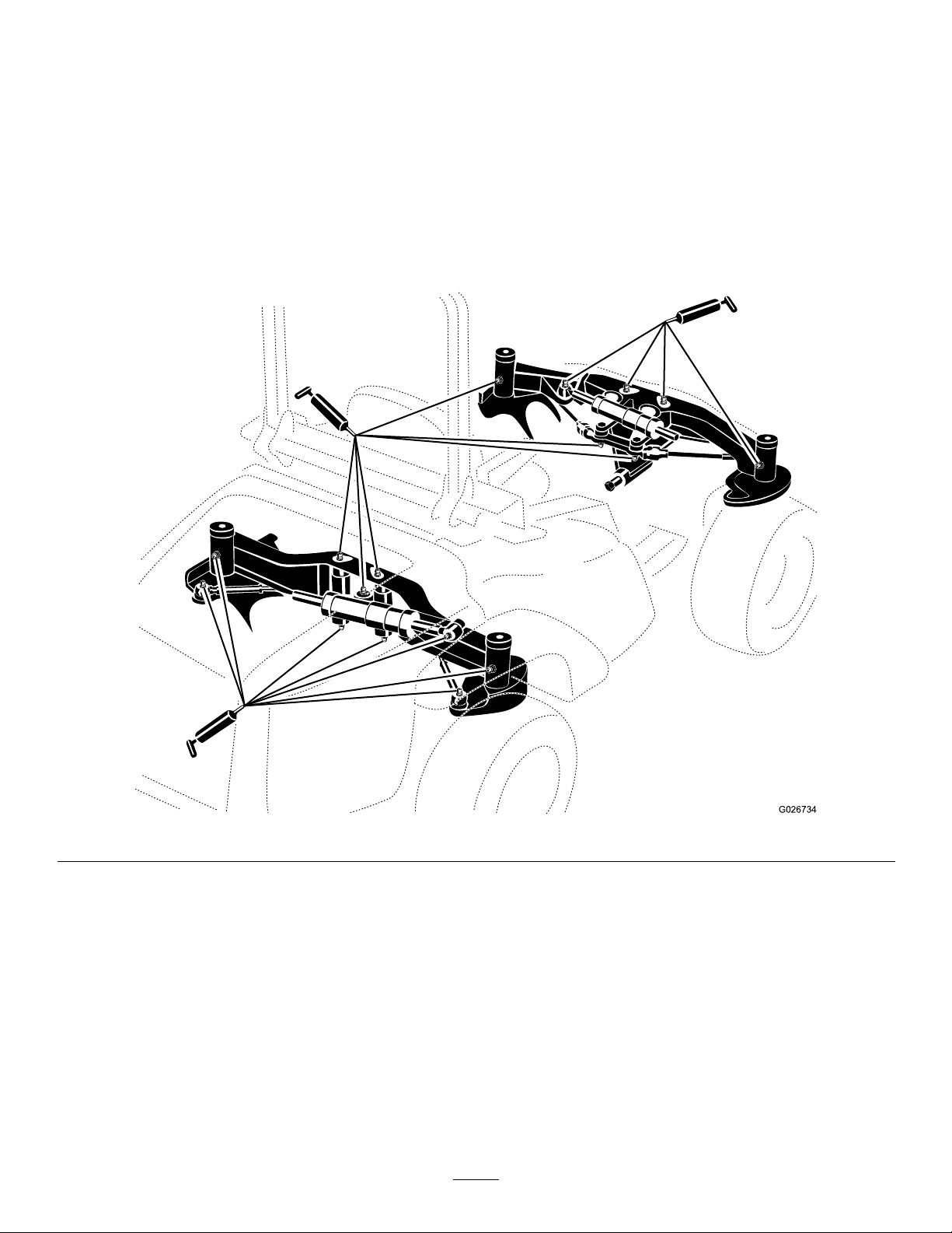
GreasingtheBearingsand Bushings
ServiceInterval:Beforeeachuseordaily
Every50hours
Themachinehasgreasettingsthatyoumustlubricate
regularlywithNo.2lithiumgrease.Also,lubricatethe
machineimmediatelyaftereverywashing.
1.Wipethegreasettingscleansothatforeignmatteris
notforcedintothebearingorbushing.
2.Pumpgreaseintothettings.
3.Wipeoffanyexcessgrease.
Note:Toaccessthegreasettingsoftherearsteering
linkage,removethestoragecompartment.
Note:Jackthemachineofftheoortoallowbetter
greasemigrationthroughboththeupperandlowerkingpin
bushings.Greasemustbeobservedpurgingoutofboththe
topandthebottomoftheaxlecasting/bushingassembly
areasofall4kingpinassemblies.
Note:Bearinglifecanbenegativelyaffectedbyimproper
washingprocedures.Donotwashthemachinewhenitisstill
hot,andavoiddirectinghigh-pressureorhigh-volumespray
atthebearingsorseals.
Figure24
EngineMaintenance
ServicingtheAirCleaner
ServiceInterval:Beforeeachuseordaily—Checkthe
air-cleanerindicator
Every400hours—Servicetheaircleaner(earlierifthe
aircleanerindicatorshowsred,andmorefrequentlyin
extremelydirtyordustyconditions).
Checktheair-cleanerbodyfordamage,whichcouldcausean
airleak.Replaceitifitisdamaged.Checkthewholeintake
systemforleaks,damage,orloosehoseclamps.
30
Page 31
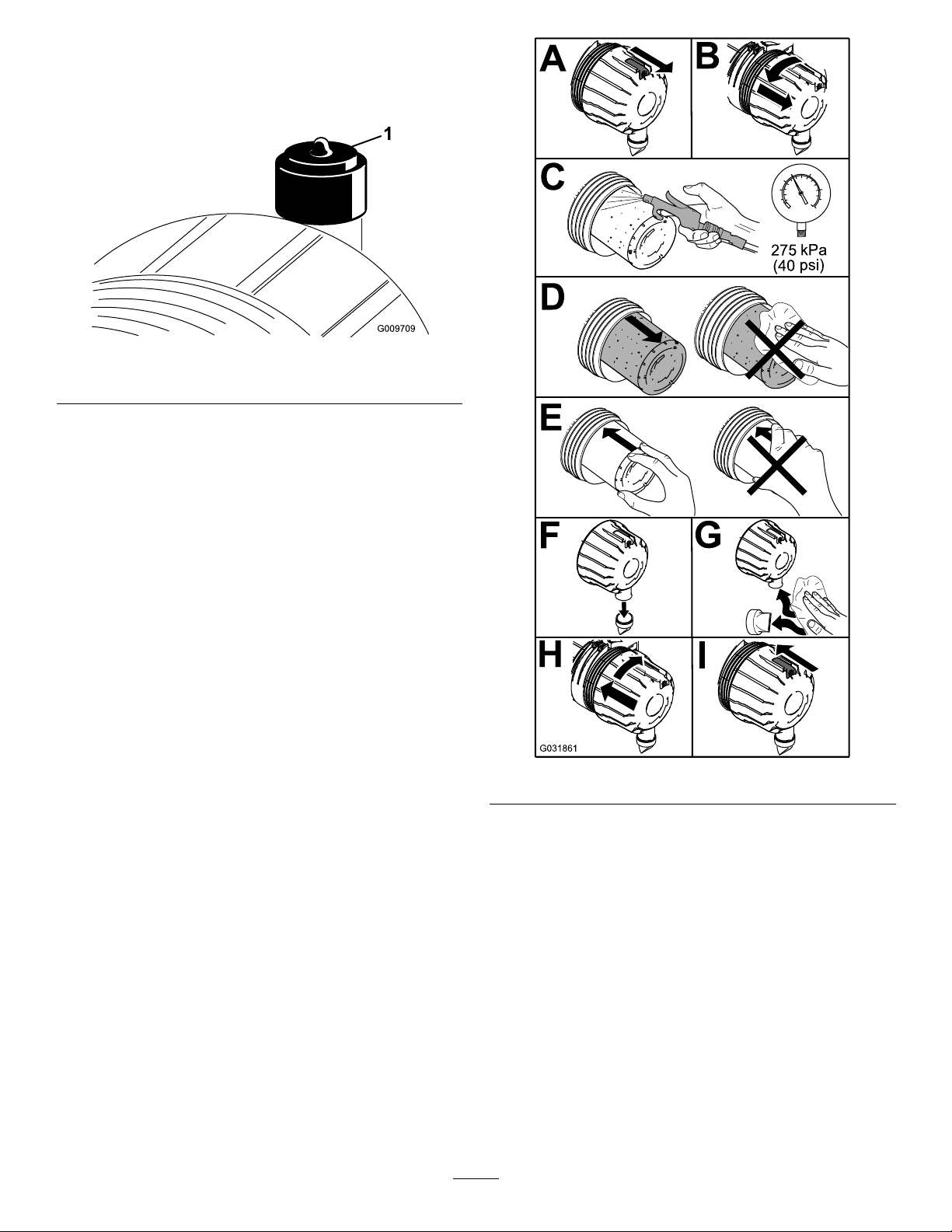
Servicetheair-cleanerlteronlywhentheserviceindicator
requiresit(Figure25).Changingtheairlterbeforeitis
necessaryonlyincreasesthechanceofdirtenteringtheengine
whenyouremovethelter.
Figure25
1.Air-cleanerindicator
Important:Besurethatthecoverisseatedcorrectly
andsealswiththeair-cleanerbody.
1.Replacetheaircleaner(Figure26).
Figure26
Note:Donotcleantheusedelementduetothe
possibilityofdamagetotheltermedia.
Important:Neverattempttocleanthesafetylter
(Figure27).Replacethesafetylterafterevery3
primarylterservices.
31
Page 32
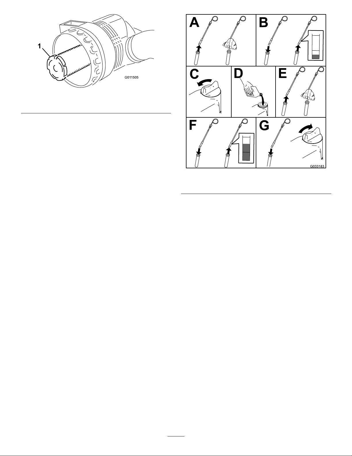
Figure27
1.Air-cleanersafetylter
2.Resettheindicator(Figure25)ifitshowsred.
CheckingtheEngine-OilLevel
ServiceInterval:Beforeeachuseordaily
Theengineisshippedwithoilinthecrankcase;however,
youmustchecktheoillevelbeforeandafterrststarting
theengine.
Thecrankcasecapacityis5.2L(5.5USqt)withthelter.
Usehigh-qualityengineoilthatmeetsthefollowing
specications:
•APIClassicationLevelRequired:CJ-4orhigher.
•Preferredoil:SAE15W -40,above-18°C(0°F)
•Alternateoil:SAE10W-30or5W-30(alltemperatures)
Important:UsingnonCJ-4orhigheroilwillcause
DPFplugginganddamagetheengine.
ToroPremiumEngineoilisavailablefromyourdistributor
ineither15W-40or10W-30viscosity.SeethePartsCatalog
forpartnumbers.
Note:Thebesttimetochecktheengineoiliswhenthe
engineiscoolbeforeithasbeenstartedfortheday.Ifithas
alreadybeenrun,allowtheoiltodrainbackdowntothe
sumpforatleast10minutesbeforechecking.Iftheoillevelis
atorbelowtheAddmarkonthedipstick,addoiltobringthe
oilleveltotheFullmark.Donotoverll.Iftheoillevelis
betweentheFullandAddmarks,nooiladditionisrequired.
Figure28
1.Dipstick
2.Oil-llcap
ChangingtheEngineOiland Filter
ServiceInterval:Every250hours
1.Starttheengineandletitrun5minutestoallowthe
oiltowarmup.
2.Parkthemachineonalevelsurface,shutofftheengine,
removethekey ,andwaitforallmovingpartstostop
beforeleavingtheoperatingposition.
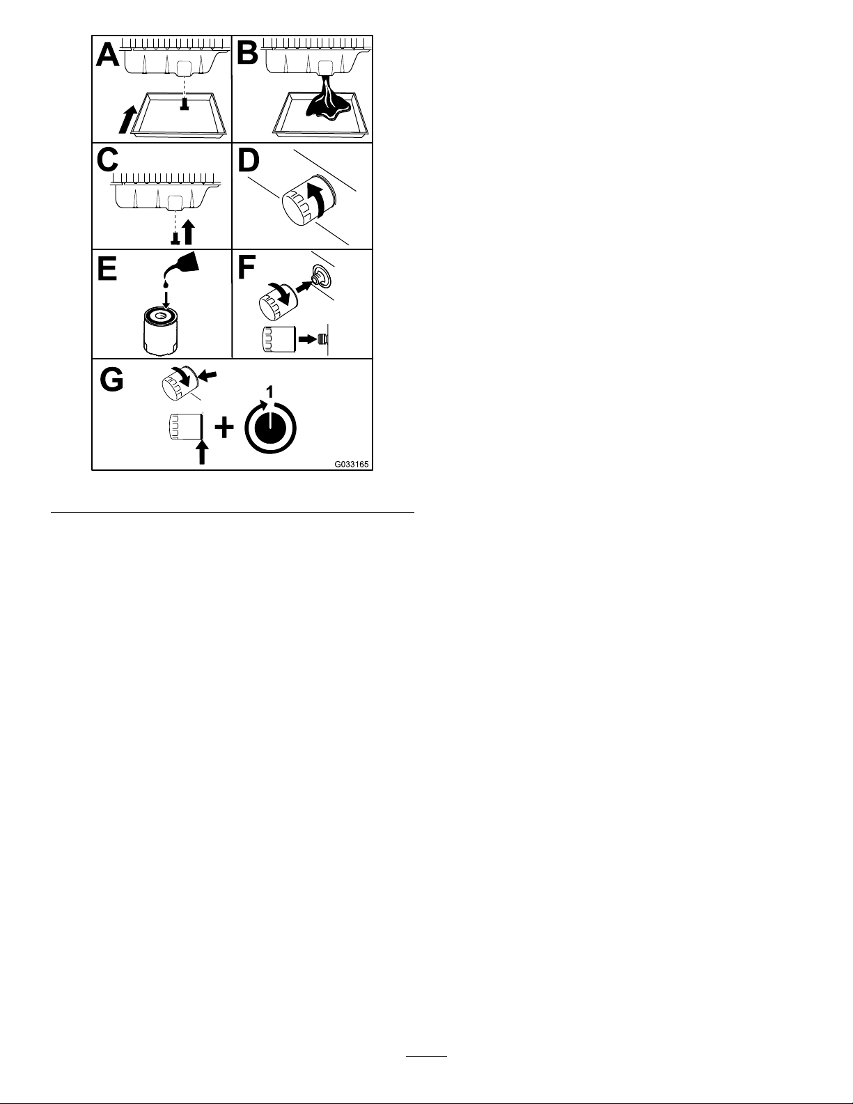
3.Replacetheengineoilandlter(Figure29).
1.Parkthemachineonalevelsurface.
2.Removethedipstick,wipeitclean,installthedipstick
intothetube,andpullitoutagain.Theoillevelshould
bebetweenthefullandaddmarks(Figure28).
32
Page 33
IftheDPFisnotcleanedatthe50g/Llevel,theenginewill
continuetorunatthede-rated85%powerleveluntiltheash
accumulationreaches60g/L.Whentheashlevelreaches60
g/L,theenginewillsendoutafault(SPN3720,FMI0)and
theenginewillde-rateto50%power.Atthistime,theDPF
isfullypluggedandneedstoberemovedandreplacedwitha
cleanDPF.AYanmardiagnostictoolwillneedtobeusedto
resettheengineECUafteracleanDPFisinstalled.
ForinformationonservicingtheDieselParticulateFilter
(DPF),refertotheservicemanualorcontactyourToro
distributor.
ServicingtheDieselOxidation Catalyst(DOC)
ServiceInterval:Every6,000hours
ForinformationonservicingtheDieselOxidationCatalyst
(DOC),refertotheservicemanualorcontactyourToro
distributor.
Figure29
4.Addoiltothecrankcase;refertoCheckingthe
Engine-OilLevel(page32).
ServicingtheDiesel ParticulateFilter(DPF)
ServiceInterval:WheninstructedbytheInfoCenter
TheDPFrequiresremovalandprofessionalcleaningafterit
hasaccumulatedover50g/Lofash.TheInfoCenterwill
warntheoperatorinphaseswhenthisDPFmaintenanceis
due.Therstwarningwilloccurwhentheashaccumulation
reaches48g/Landwillshowanadvisory(number179)on
theInfoCenter.Thisadvisoryismeanttogiveyourservice
departmentnoticethatyourmachinewillsoonneedDPF
cleaningmaintenance.Ifyouwouldliketoknowthecurrent
levelofashinanyofyourToroTier4products,youcan
nditbygoingtotheServicemenuoftheInfoCenterafter
enteringthePIN.Reference“UsingtheInfoCenterLCD
Display”formoreinformationonaccessingprotectedmenus.
Whentheashaccumulationreaches50g/L,youwillseea
enginefaultcomeupontheInfoCenter(SPN3720,FMI16)
toalerttheoperatorthattheDPFneedscleaning.Alsoatthe
50g/Llevel,theenginewillde-rateitspowerto85%.Atthis
time,theDPFneedstoberemovedandreplacedwithaclean
DPF.AYanmardiagnostictoolwillneedtobeusedtoreset
theengineECUafteracleanDPFisinstalled.Talkwithyour
Torodistributorandseeyourservicemanualformoredetails
ontheremovalandinstallationoftheDPF .
33
Page 34
FuelSystem
Maintenance
Note:RefertoRecommendedFuel(page16)fortheproper
fuelrecommendations.
ServicingtheWaterSeparator
ServiceInterval:Beforeeachuseordaily
Every400hours
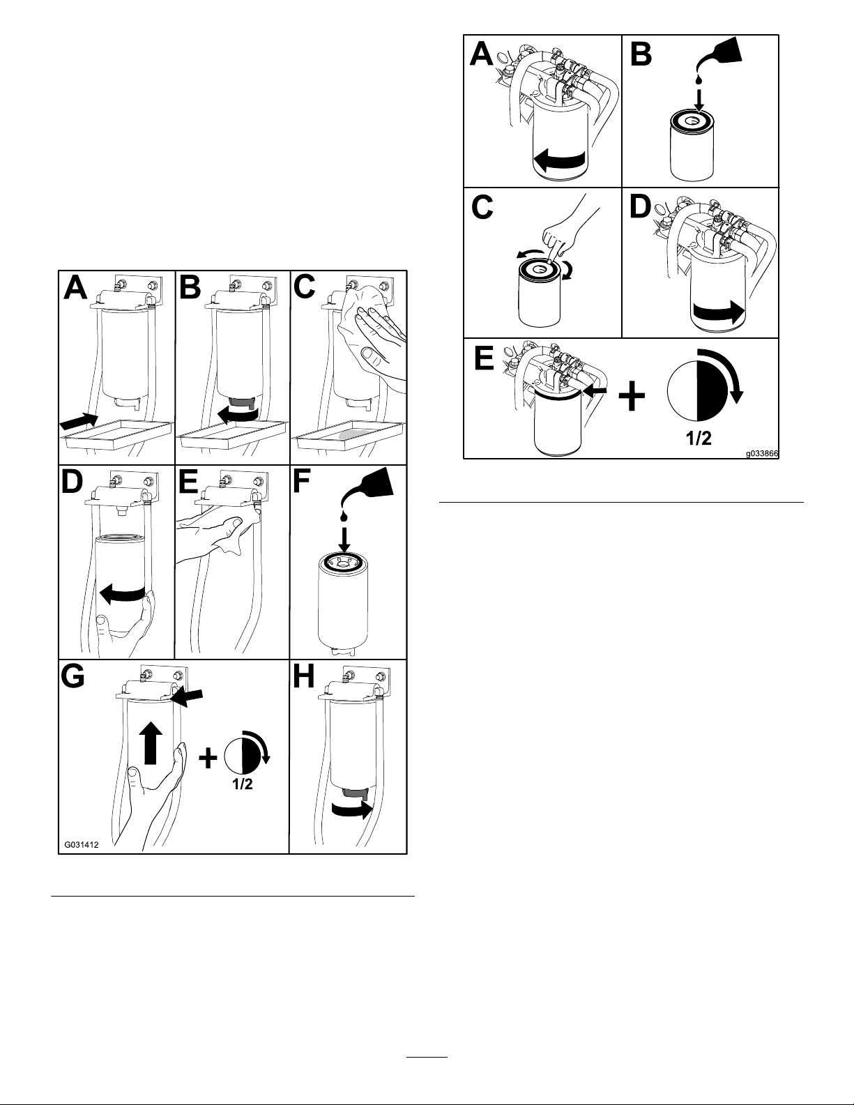
ServicethewaterseparatorasshowninFigure30.
Figure30
Figure31
2.Starttheengineandcheckforfuelleaksaroundthe
lterhead.
CheckingtheFuelLinesand Connections
ServiceInterval:Every400hours
Inspectthefuellinesandconnectionsfordeterioration,
damage,orlooseconnections.
CleaningtheFuelPick-Up TubeScreen
Thefuelpick-uptube,locatedinsidethefueltank,isequipped
withascreentohelppreventdebrisfromenteringthefuel
system.Removethefuelpick-uptubeandcleanthescreen
asrequired.
ServicingtheEngineFuel Filter
ServiceInterval:Every400hours
1.Cleantheareaaroundthelterhead(Figure31).
34
Page 35
ElectricalSystem
g014186
1
25
10
25
10
25
15
10
10
Maintenance
Important:Wheneverworkingwiththeelectrical
system,alwaysdisconnectthebatterycables,negative
(-)cablerst,topreventpossiblewiringdamagefrom
short-outs.
ElectricalSystemSafety
•Disconnectthebatterybeforerepairingthemachine.
Disconnectthenegativeterminalrstandthepositive
last.Connectthepositiveterminalrstandthenegative
last.
•Batteryacidispoisonousandcancauseburns.Avoid
contactwithyourskin,eyes,andclothing.Protectyour
face,eyes,andclothingwhenworkingwithabattery.
•Batterygasescanexplode.Keepcigarettes,sparks,and
amesawayfromthebattery.
•Chargethebatteriesinanopen,well-ventilatedarea,
awayfromsparksandames.Unplugthechargerbefore
connectingordisconnectingthebattery.Wearprotective
clothinganduseinsulatedtools.
•Donotuseapressurewashernearanyelectronic
components.
WARNING
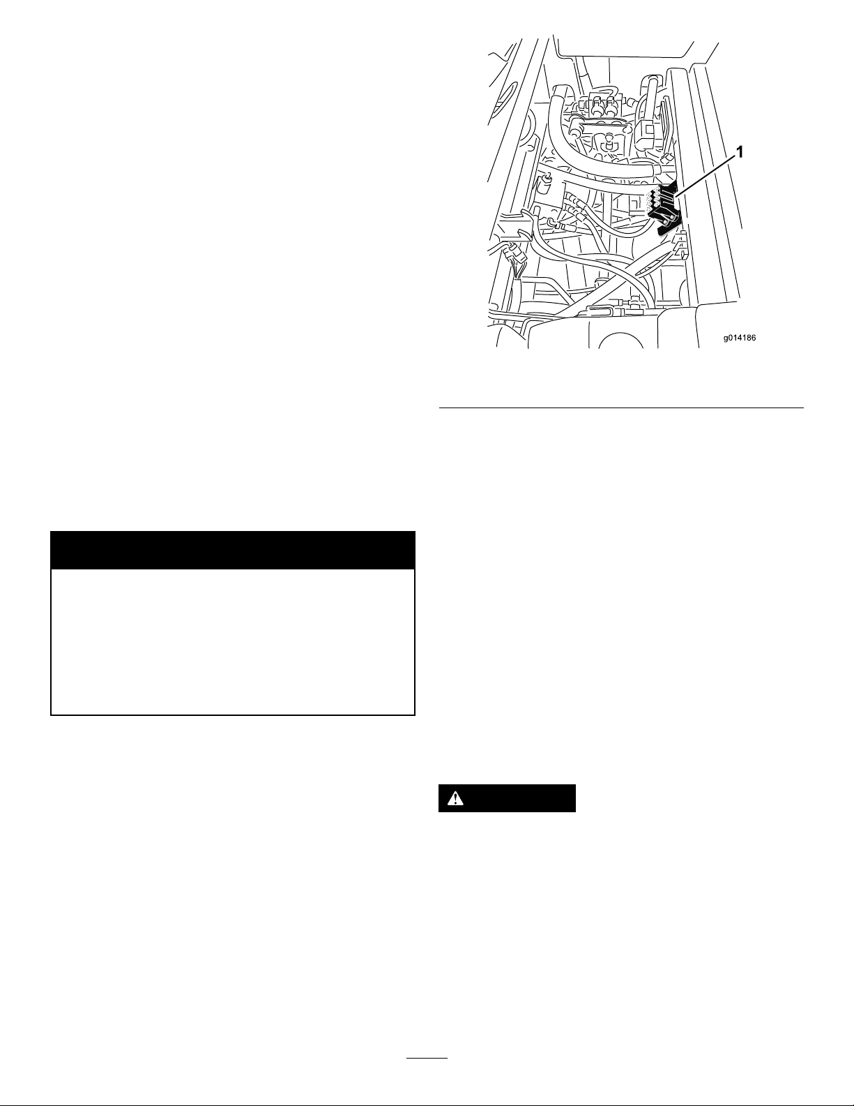
Figure32
1.Fuseblock
ServicingtheBattery
ServiceInterval:Every50hours
Keepthetopofthebatteryclean.Ifyoustorethemachinein
alocationwheretemperaturesareextremelyhigh,thebattery
willrundownmorerapidlythanifthemachineisstoredin
alocationwheretemperaturesarecool.
CALIFORNIA
Proposition65Warning
Batteryposts,terminals,andrelated
accessoriescontainleadandleadcompounds,
chemicalsknowntotheStateofCalifornia
tocausecancerandreproductiveharm.
Washhandsafterhandling.
CheckingtheFuses
Ifthemachinestopsorhasotherelectricalsystemissues,
checkthefuses.Graspeachfuseinturnandremovethem1
atatime,checkingtoseeifanyareblown.Ifyouneedto
replaceafuse,alwaysusethesametypeandamperage
ratedfuseastheoneyouarereplacing,otherwiseyoucould
damagetheelectricalsystem(refertothedecalnexttothe
fusesforadiagramofeachfuseanditsamperage).
Thefusesarelocatedundertheseat(Figure32).
Keepthetopofthebatterycleanbywashingitperiodically
withabrushdippedinammoniaorbaking-sodasolution.
Flushthetopsurfacewithwateraftercleaningit.Donot
removethellcapswhilecleaningthebattery.
Thebatterycablesmustbetightontheterminalstoprovide
goodelectricalcontact.
Ifcorrosionoccursattheterminals,disconnectthecables,
negative(-)cablerst,andscrapetheclampsandterminals
separately.Connectthecables,positive(+)cablerst,and
coattheterminalswithpetroleumjelly.
WARNING
Batteryterminalsormetaltoolscouldshortagainst
metalmachinecomponents,causingsparks.Sparks
cancausethebatterygassestoexplode,resulting
inpersonalinjury.
•Whenremovingorinstallingthebattery,donot
allowthebatteryterminalstotouchanymetal
partsofthemachine.
•Donotallowmetaltoolstoshortbetween
thebatteryterminalsandmetalpartsofthe
machine.
35
Page 36
WARNING
g026089
Incorrectbatterycableroutingcoulddamagethe
machineandcablescausingsparks.Sparkscan
causethebatterygassestoexplode,resultingin
personalinjury.
•Alwaysdisconnectthenegative(black)battery
cablebeforedisconnectingthepositive(red)
cable.
•Alwaysconnectthepositive(red)batterycable
beforeconnectingthenegative(black)cable.
StoringtheBattery
Ifthemachinewillbestoredmorethan30days,removethe
batteryandchargeitfully.Eitherstoreitonashelforon
themachine.Leavethecablesdisconnectedifitisstoredon
themachine.Storethebatteryinacoolatmospheretoavoid
quickdeteriorationofthechargeinthebattery.Toprevent
thebatteryfromfreezing,makesurethatitisfullycharged.
Thespecicgravityofafullychargedbatteryis1.265to1.299.
DriveSystem
Maintenance
CheckingtheTirePressure
ServiceInterval:Every50hours
Checkthepressureafterevery50operatinghoursormonthly,
whicheveroccursrst.
Maintaintheairpressureinthefrontandreartires.The
correctairpressureis172kPa(25psi)inthereartiresand
103kPa(15psi)inthefronttires.Ifacabisinstalledonthe
machine,thefrontandreartiresshouldbeinatedto172
kPa(25psi).Uneventirepressurecancauseunevencut.T o
getthemostaccuratepressurereading,checkthetireswhen
theyarecold.
CorrectingSteering Misalignment
1.Pressthesteeringselectorswitchtotherearward
4-wheel-steerposition(Figure33).
Figure33
1.Steering-selectorswitch
2.Onapavedordirtsurface,turnthesteeringwheelto
theleftorrightandcontinueturninguntilall4wheels
havestoppedturning.Automaticsynchronizationof
wheelalignmentshouldoccur.
Important:Doingthisprocedureonturfcan
resultinturfdamagedirectlyundereachofthe
turningtires.
36
Page 37
CoolingSystem
G014515
Maintenance
CoolingSystemSafety
CAUTION
Dischargeofhot,pressurizedcoolantortouchinga
hotradiatorandsurroundingpartscancausesevere
burns.
•Donotremovetheradiatorcapwhentheengine
ishot.Alwaysallowtheenginetocoolatleast15
minutesoruntiltheradiatorcapiscoolenough
totouchwithoutburningyourhandbefore
removingtheradiatorcap.
•Donottouchtheradiatorandsurroundingparts
thatarehot.
3.Installthecapoftheexpansiontank.
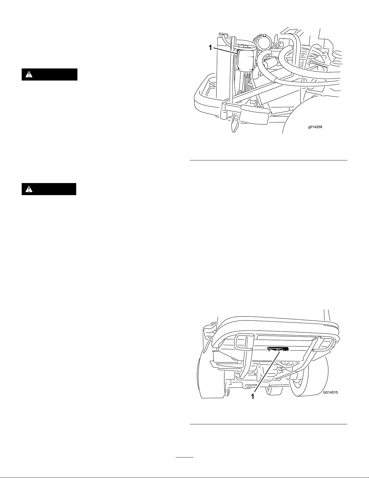
Figure34
1.Expansiontank
CleaningtheRadiator
DANGER
Swallowingenginecoolantcancausepoisoning.
•Donotswallowenginecoolant.
•Keepoutofreachfromchildrenandpets.
CheckingtheCoolingSystem
ServiceInterval:Beforeeachuseordaily
Thecoolingsystemislledwitha50/50solutionofwater
andpermanentethylene-glycolantifreeze.Checkthelevelof
thecoolantintheexpansiontankatthebeginningofeachday
beforestartingtheengine.Thecapacityofthecoolingsystem
is7.5L(6USqt).
1.Checkthelevelofthecoolantintheexpansiontank
(Figure34).Thecoolantlevelshouldbebetweenthe
marksonthesideofthetank.
2.Ifthecoolantlevelislow,removetheexpansion-tank
capandreplenishthesystem.Donotoverllthe
coolingsystem.
ServiceInterval:Beforeeachuseordaily
Topreventtheenginefromoverheating,keeptheradiator
clean.Normally,checktheradiatordailyand,ifnecessary,
cleananydebrisofftheseparts.Checkandcleantheradiator
frequentlyinextremelydustyanddirtyconditions.
Note:Ifthemowerdeckorengineshutsoffdueto
overheating,rstchecktheradiatorforexcessivebuildupof
debris.
Cleantheradiatorasfollows:
1.Openthehoodandsecuretheproprod.
2.Loosentheangenutsecuringtheclean-outcoverto
theundersideoftherearframe(Figure35).Rotatethe
covertothesidetoexposetheclean-outholeinthe
frame.
Figure35
1.Clean-outcover
3.Workingfromthefansideoftheradiator,blowout
debriswithlow-pressure(345kPa[50psi])compressed
37
Page 38
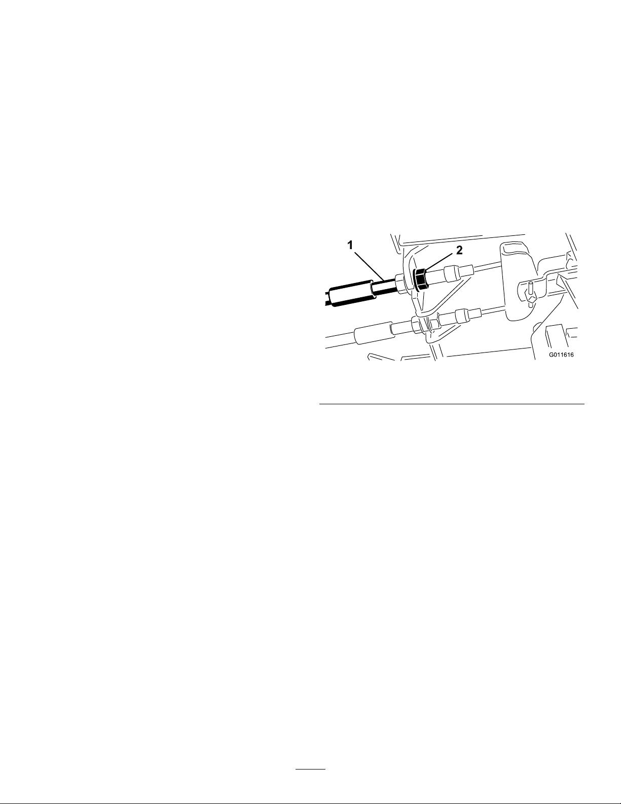
air(donotusewater).Repeatthestepfromthefront
1
2
oftheradiatorandagainfromthefanside.
4.Aftertheradiatoristhoroughlycleaned,cleanoutany
debristhatmayhavecollectedinthechannelatthe
radiatorbaseandaroundtheframe.Also,cleanoutthe
enginecompartmentandthebrakelinkagetoensure
optimumperformance.
5.Closetheclean-outcoverandsecuretheangenut.
6.Closethehood.
BrakeMaintenance
AdjustingtheServiceBrakes
Adjusttheservicebrakeswhenthereismorethan25mm(1
inch)offreetravelofthebrakepedal,orwhenthebrakes
donotworkeffectively.Freetravelisthedistancethebrake
pedalmovesbeforeyoufeelbrakingresistance.
Note:Usethewheelmotorbacklashtorockthedrums
backandforthtoensurethatthedrumsarefreepriortoand
afteradjustment.
1.Toreducefreetravelofthebrakepedals,tightenthe
brakesbylooseningthefrontnutonthethreadedend
ofthebrakecable(Figure36).
Figure36
1.Brakecables2.Frontnuts
2.Tightentherearnuttomovethecablebackwarduntil
thebrakepedalshave1.27to1.9cm(1/2to3/4inch)
offreetravel,beforewheellockupisachieved.
3.Tightenthefrontnuts,ensuringthatbothcables
actuatethebrakessimultaneously.
38
Page 39
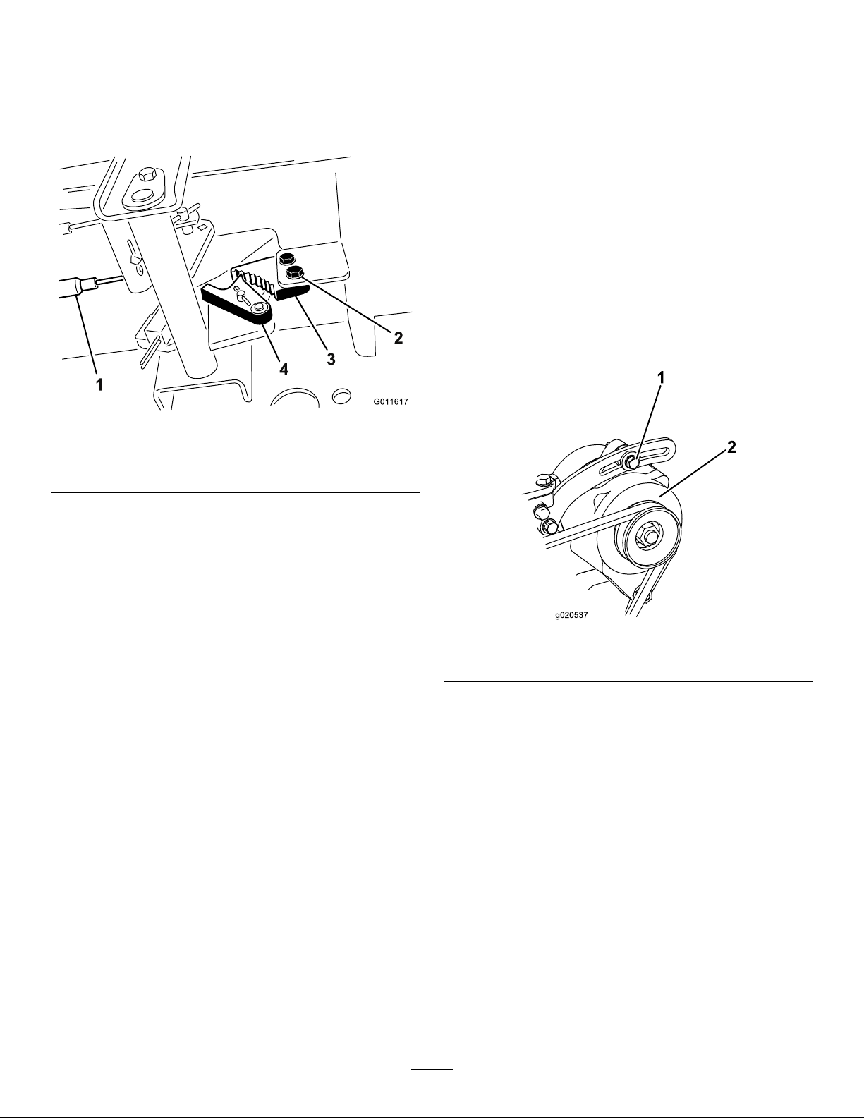
AdjustingtheParkingBrake
1
4
3
2
g020537
1
2
Iftheparkingbrakefailstoengage,anadjustmenttothe
brakepawlisrequired.
1.Loosenthe2screwssecuringtheparking-brakepawl
totheframe(Figure37).
Figure37
1.Brakecables3.Parking-brakepawl
2.Screws(2)
4.Brakedetent
BeltMaintenance
CheckingtheAlternatorBelt
ServiceInterval:Aftertherst10hours
Every100hours
Checktheconditionandtensionofthebelt(Figure38)after
every100operatinghours.
1.Propertensionwillallow10mm(3/8inch)deection
whenaforceof44N(10lb)isappliedonthebelt
midwaybetweenthepulleys.
2.Ifthedeectionisnot10mm(3/8inch),loosenthe
alternatormountingbolts(Figure38).Increaseor
decreasethetensionofthealternatorbeltandtighten
thebolts.Checkthedeectionofthebeltagainto
ensurethatthetensioniscorrect.
2.Presstheparking-brakepedalforwarduntilthebrake
detentcompletelyengagesonthebrakepawl(Figure
37).
3.Tightenthe2screwstolocktheadjustment.
4.Pressthebrakepedaltoreleasetheparkingbrake.
5.Checktheadjustmentandadjustitagainasrequired.
Figure38
1.Mountingbolt2.Alternator
39
Page 40
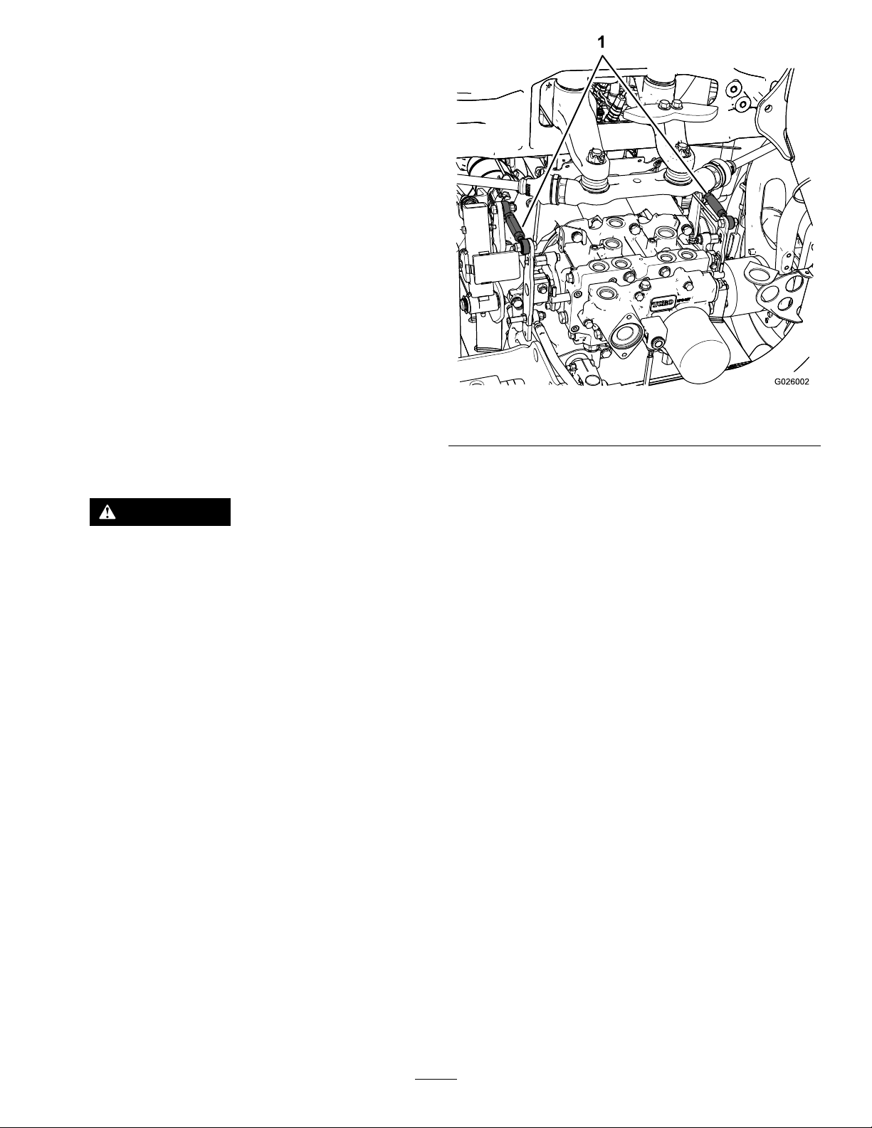
ControlsSystem
Maintenance
AdjustingtheTractionDrive forNeutral
Note:Ifthemachinehasrecentlyhadthehydraulicuid
changedorthetractionmotorsorhosesreplaced,anyair
trappedinthesystemwillhavetobeworkedoutpriorto
performingthisprocedure.Thiscanbeaccomplishedby
operatingthemachineinforwardandreverseforafew
minutesandthenreplenishingtheoilasrequired.
Note:Whenpositionedonalevelsurface,themachinemust
notcreepwhenthetractionpedalisreleased.
1.Parkthemachineonalevelsurface,shutoffthe
engone,andlowerthecuttingunittotheoor.
2.Jackuptherearofthemachineuntilthereartiresare
offtheshopoor.Supportthemachinewithjack
standstopreventitfromfallingaccidentally.
Note:On4-wheel-drivemodels,thefronttiresmust
alsobeofftheshopoorandsupportedbyjackstands.
WARNING
Theenginemustberunningsothatthis
adjustmentcanbeperformed.Thiscould
causepersonalinjury.
Keephands,feet,face,andotherbodyparts
awayfromanyhotpartsoftheengineandany
rotatingparts.
3.Starttheengine,setthethrottletotheSlowposition,
andobservewhichdirectionthereartiresrotate.
Important:Makesurethatthetractionpedalisin
theNEUTRALposition.
•Iftheleftreartireisrotating,loosenthejamnuts
ontheleftsidetransmissioncontrolrod(Figure
39).
Figure39
1.Transmissioncontrolrods
•Iftheleftreartireisrotatinginreverse,lengthen
therodbyslowlyturningtherodcounterclockwise
(asviewedfromthefront)untiltheleftreartire
stopsrotatingorhasminimalrotationinreverse.
•Iftheleftreartireisrotatingforward,shortenthe
rodbyslowlyturningtherodclockwise(asviewed
fromthefront)untiltheleftreartirestopsrotating.
4.MovethethrottletotheFastposition.Makesurethat
thewheelremainsstoppedorhasminimalrotationin
reverse.Adjustitasrequired.
5.Tightenthejamnuts.
6.Repeattheprocedurefortherightreartire,ifrequired,
byusingtheright-sidetransmissioncontrolrod.
7.Stoptheengine.Removethejackstandsandlowerthe
machinetotheshopoor.
8.Testdrivethemachinetomakesurethatitdoesnot
creep.
Note:Theforwardendofthecontrolrodhasa
left-handthread.Therearendoftherod,which
isconnectedtothetransmission,hasaright-hand
thread.
AdjustingtheMaximum GroundSpeed
1.DisengagethePTO,releasethetractionpedaltothe
NEUTRALposition,andsettheparkingbrake.
2.MovethethrottlelevertotheSlowposition,shutoff
theengine,removethekey,andwaitforallmoving
partstostopbeforeleavingtheoperatingposition.
3.Loosenthejamnutonthestopboltforthetraction
pedal(Figure40).
40
Page 41
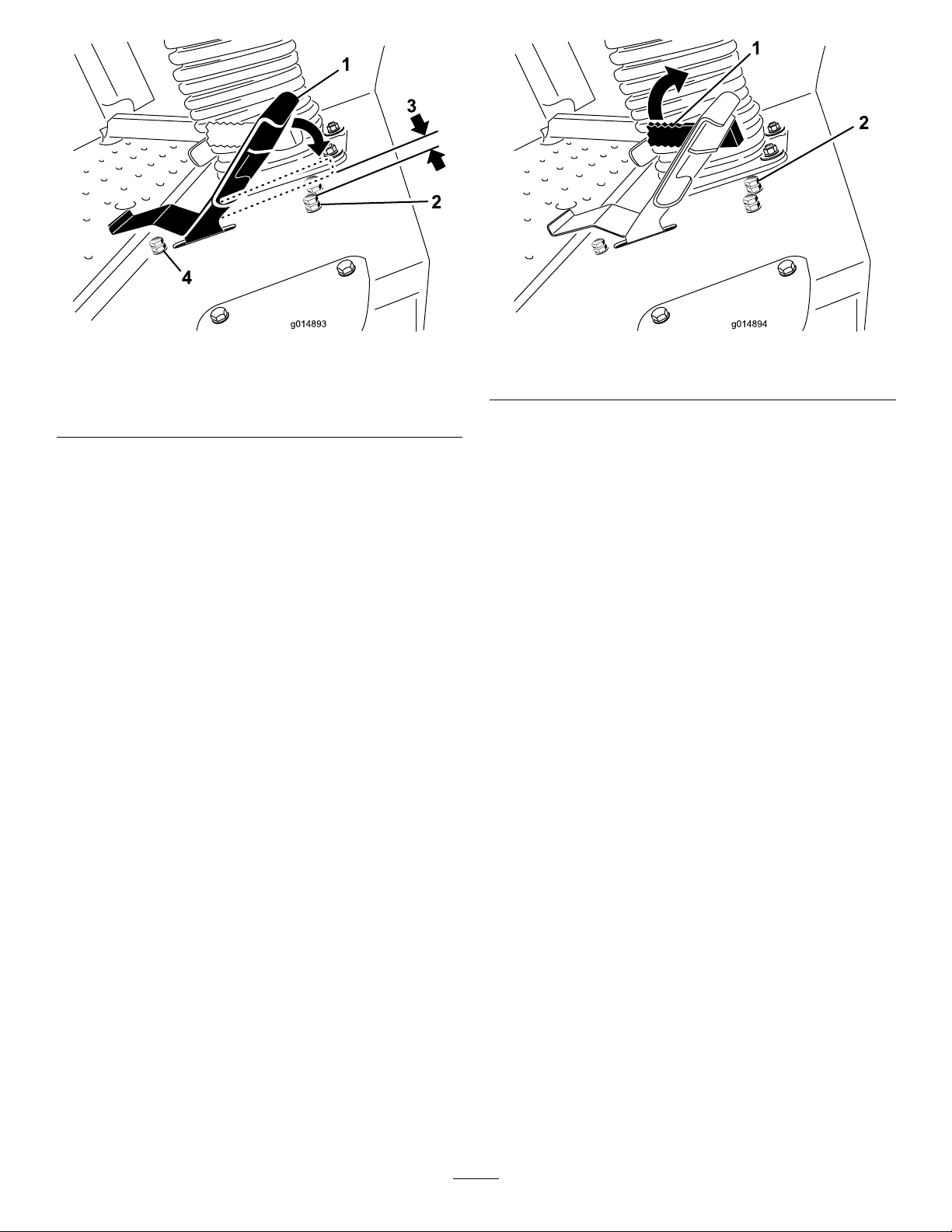
Figure40
Figure41
1.Tractionpedal
2.Stopboltwithjamnut
(forward)
3.1.5mm(0.060inch)
4.Stopboltwithjamnut
(reverse)
4.Adjustthestopboltallthewayinward(awayfromthe
tractionpedal).
5.Pushthetractionpedalwithyourhandalltheway
forwardwithlightpressureuntilitstops,andholdit
there.Maintainonlylightpressureonthepedalwhen
pushingittothefullforwardposition.
6.Withtheseatintheraisedposition,verifythatyouare
notoverloadingthelinkagebymakingsurethatthe
transmissiondoesnotmovewhenyoupressthepedal
tothestop.
7.Adjustthestopboltoutward(towardthetraction
pedal)untilthereisagapof1.5mm(0.060inch)
betweentheheadofthestopboltandthebottomof
thetractionpedal.
8.Tightenthejamnuttosecurethestopboltinplace.
9.Adjustthereversestopboltifthemaximumreverse
speedisnotacceptable.
Note:Forafasterreversespeed,adjustthestopbolt
inward.Foraslowerreversespeed,adjustthestopbolt
outward.
1.Mow-speedlimiter
2.Stopboltw/jamnut
4.Threadthestopboltintoincreasethemowspeedand
outtodecreasethemowspeed.
5.Tightenthejamnuttolocktheadjustment.
6.Rotatethemow-speedlimiterdown,operatethe
machinetoverifytheadjustment,andadjustthestop
boltagainifrequired.
AdjustingtheMow-Speed Limiter
Flipthemow-speedlimiter(Figure41)forwardtolimitthe
tractionspeedofthemachine.
1.DisengagethePTO,releasethetractionpedaltothe
NEUTRALposition,andsettheparkingbrake.
2.MovethethrottlelevertotheSlowposition,shutoff
theengine,removethekey,andwaitforallmoving
partstostopbeforeleavingtheoperatingposition.
3.Loosenthejamnutonthestopboltofthemow-speed
limiter(Figure41).
41
Page 42
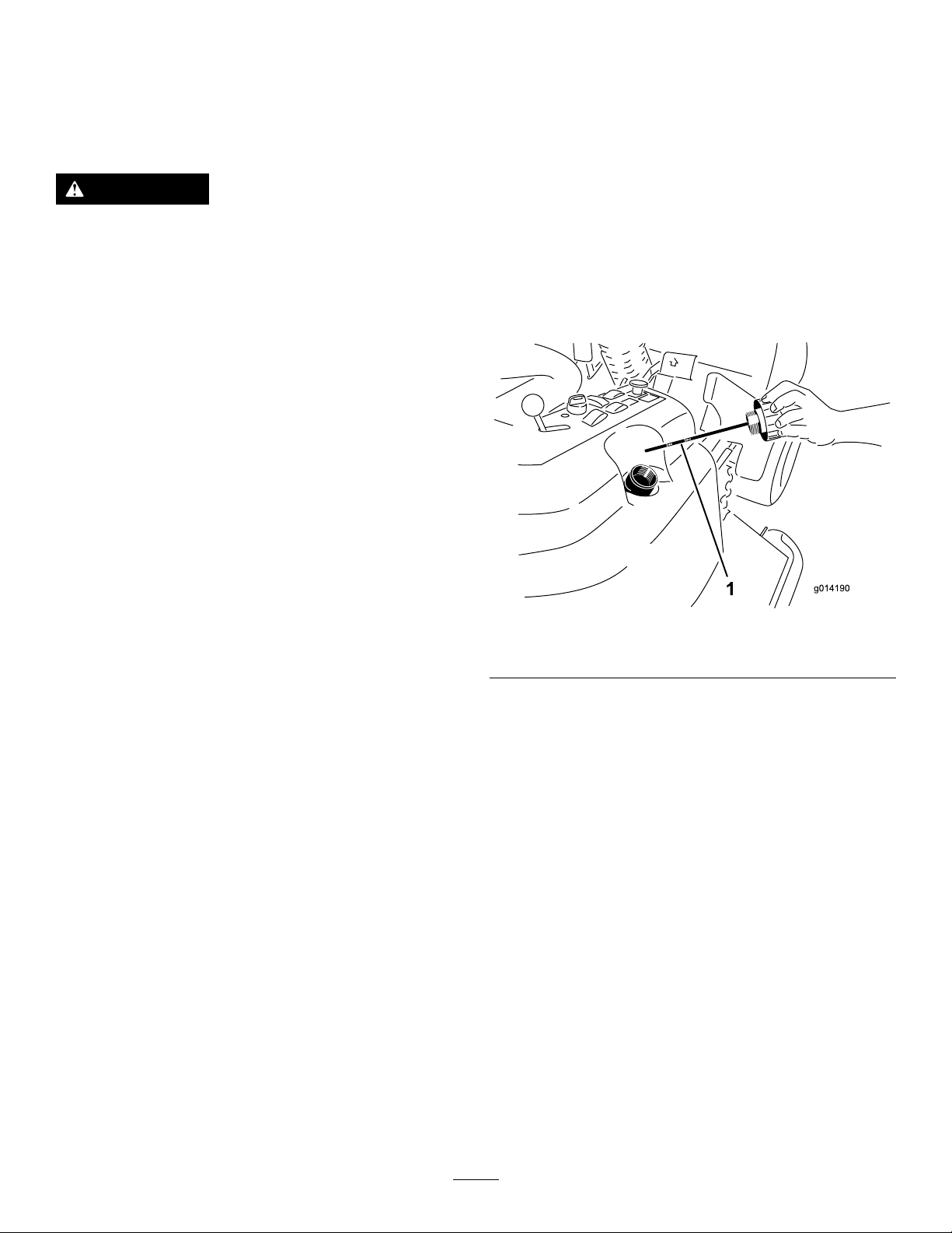
HydraulicSystem
2.Removethehydraulic-llcap(Figure42)fromtheller
neck.
Maintenance
HydraulicSystemSafety
WARNING
Hydraulicuidescapingunderpressurecan
penetrateskinandcauseinjury.
•Ensurethatallhydraulic-uidhosesand
linesareingoodconditionandallhydraulic
connectionsandttingsaretightbefore
applyingpressuretothehydraulicsystem.
•Keepyourbodyandhandsawayfrompinhole
leaksornozzlesthatejecthigh-pressure
hydraulicuid.
•Usecardboardorpapertondhydraulicleaks.
•Safelyrelieveallpressureinthehydraulicsystem
beforeperforminganyworkonthehydraulic
system.
•Seekimmediatemedicalattentionifuidis
injectedintoskin.
3.Removethedipstickandwipeitwithacleanrag
(Figure42).
4.Screwthedipstickallthewayintothellerneck;then
removeit,andchecktheleveloftheuid(Figure42).
Ifthelevelisnotwithinthenotchedareaofthe
dipstick,addenoughhigh-qualityhydraulicuidto
raisetheleveltowithinthenotchedarea.Donot
overllthehydraulicsystem.
5.Replacethedipstickandthreadthellcapnger-tight
ontothellerneck.
6.Checkallhosesandttingsforleaks.
CheckingtheHydraulic System
ServiceInterval:Beforeeachuseordaily
Thereservoirislledatthefactorywithapproximately17L
(18USqt)ofhigh-qualitytractortransmission/hydraulic
uid.Therecommendedreplacementuidisasfollows:
ToroPremiumAllSeasonHydraulicFluid(Availablein
19L(5gallon)pailsor208L(55gallon)drums.SeetheParts
CatalogoryourToroDistributorforpartnumbers).
Alternateuids:IftheTorouidisnotavailable,Mobil®424
hydraulicuidmaybeused.
Note:Torowillnotassumeresponsibilityfordamagecaused
byimpropersubstitutions.
Note:Manyhydraulicuidsarealmostcolorless,makingit
difculttospotleaks.Areddyeadditiveforthehydraulic
systemoilisavailablein20ml(2/3oz)bottles.Onebottle
issufcientfor15to22L(4to6USgallons)ofhydraulic
uid.Orderpartnumber44-2500fromyourauthorizedToro
distributor.
1.Positionthemachineonalevelsurface.Releasethe
tractionpedaltotheNEUTRALpositionandstartthe
engine.Runtheengineatthelowestpossiblespeedto
purgethesystemofair.DonotengagethePTO.
Raisethedecktoextendtheliftcylinders,shutoffthe
engine,andremovethekey.
Figure42
1.Dipstick
ChangingtheHydraulicFluid AndFilter
ServiceInterval:Aftertherst200hours
Every800hours
1.DisengagethePTO,releasethetractionpedaltothe
NEUTRALpositionandsettheparkingbrake.
2.MovethethrottlelevertotheSLOWposition,shutoff
theengine,removethekey,andwaitforallmoving
partstostopbeforeleavingtheoperatingposition.
3.Placealargepanunderthehydraulicreservoirand
transmissioncaseandremovetheplugs,drainingallof
thehydraulicuid(Figure43).
42
Page 43
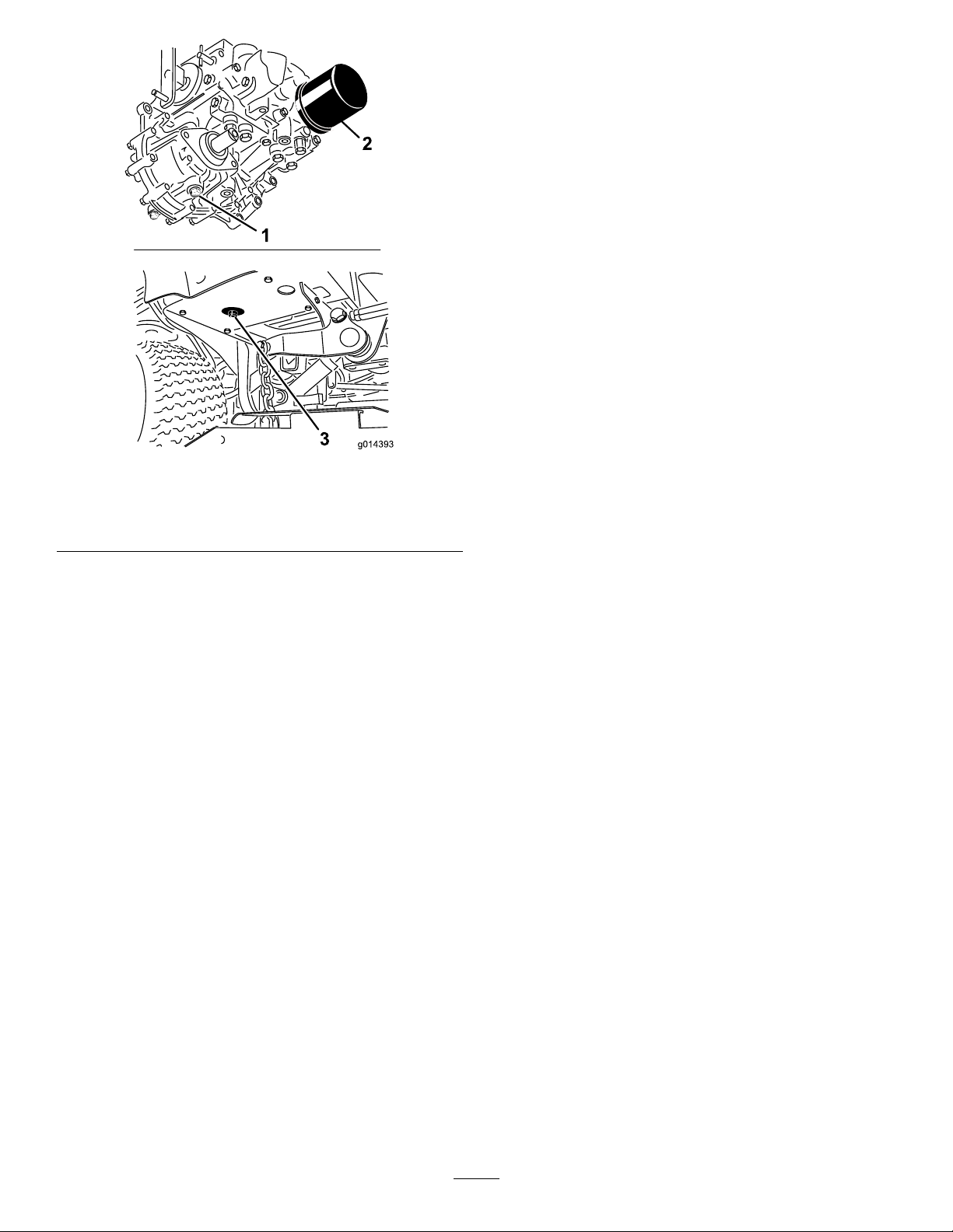
Figure43
Cleaning
WasteDisposal
Engineoil,batteries,hydraulicuid,andenginecoolantare
pollutantstotheenvironment.Disposeoftheseaccordingto
yourstateandlocalregulations.
1.Transmission-casedrain
plug
2.Filter
4.Cleantheareaaroundthehydraulic-uidlterand
removethelter(Figure43).
5.Immediatelyinstallanewhydraulic-uidlter.
6.Installthedrainplugsinthehydraulicreservoirand
thetransmissioncase.
7.Fillthereservoirtotheproperlevel;refertoChecking
theHydraulicSystem(page42).
8.Starttheengineandcheckforuidleaks.Allowthe
enginetorunforabout5minutes,thenshutitoff.
9.After2minutes,checkthelevelofthehydraulicuid;
refertoCheckingtheHydraulicSystem(page42).
3.Hydraulic-reservoirdrain
plug
43
Page 44

Storage
PreparingtheEngine
1.Draintheengineoilfromtheoilpanandinstallthe
drainplug.
2.Removeanddiscardtheoillter.Installanewlter.
3.Filltheenginewiththedesignatedquantityofengine
oil.RefertoCheckingtheEngine-OilLevel(page32).
4.Starttheengineandrunitatidlespeedfor2minutes.
5.Drainthefuelfromthefueltank,fuellines,pump,
lter,andseparator.Flushthefueltankwithclean
dieselfuelandconnectallfuellines.
6.Thoroughlycleanandservicetheair-cleanerassembly.
7.Sealtheair-cleanerinletandtheexhaustoutletwith
weatherproofmaskingtape.
8.Checktheoil-llercapandfuel-tankcaptoensurethat
theyaresecurelyinplace.
PreparingtheMachine
1.Thoroughlycleanthemachine,thedeck,andthe
engine,payingspecialattentiontothefollowingareas:
•Radiatorandradiatorscreen
•Counterbalancesprings
•PTO-shaftassembly
•Allgreasettingsandpivotpoints
•Insideofthecontrolbox(Removethecontrol
panelforaccess.)
•Beneaththeseatplateandthetopofthe
transmission
2.Checkandadjustthetirepressure;refertoChecking
theTirePressure(page36).
3.Checkallfastenersforloosenessandtightenthemas
necessary.
4.Greaseoroilallgreasettings,pivotpoints,and
transmissionbypass-valvepins.Wipeoffanyexcess
lubricant.
5.Lightlysandandusetouch-uppaintonpaintedareas
thatarescratched,chipped,orrusted.Repairanydents
inthemetalbody.
6.Servicethebatteryandcablesasfollows:
A.Removethebatteryterminalsfromthebattery
posts.
B.Cleanthebattery,terminals,andpostswithawire
brushandbaking-sodasolution.
C.Coatthecableterminalsandbatterypostswith
Grafo112Xskin-overgrease(ToroPartNo.
505-47)orpetroleumjellytopreventcorrosion.
D.Slowlychargethebatteryfor24hoursevery60
daystopreventleadsulfationofthebattery.
44
Page 45

Notes:
45
Page 46

Notes:
46
Page 47

Notes:
47
Page 48

TheT oroWarranty
ATwo-YearLimitedWarranty
ConditionsandProductsCovered
TheToroCompanyanditsafliate,T oroWarrantyCompany,pursuant
toanagreementbetweenthem,jointlywarrantyourT oroCommercial
product(“Product”)tobefreefromdefectsinmaterialsorworkmanship
fortwoyearsor1500operationalhours*,whicheveroccursrst.This
warrantyisapplicabletoallproductswiththeexceptionofAerators
(refertoseparatewarrantystatementsfortheseproducts).Wherea
warrantableconditionexists,wewillrepairtheProductatnocosttoyou
includingdiagnostics,labor,parts,andtransportation.Thiswarranty
beginsonthedatetheProductisdeliveredtotheoriginalretailpurchaser .
*Productequippedwithanhourmeter.
InstructionsforObtainingWarrantyService
YouareresponsiblefornotifyingtheCommercialProductsDistributoror
AuthorizedCommercialProductsDealerfromwhomyoupurchasedthe
Productassoonasyoubelieveawarrantableconditionexists.Ifyouneed
helplocatingaCommercialProductsDistributororAuthorizedDealer,or
ifyouhavequestionsregardingyourwarrantyrightsorresponsibilities,
youmaycontactusat:
ToroCommercialProductsServiceDepartment
ToroWarrantyCompany
811 1LyndaleAvenueSouth
Bloomington,MN55420-1196
952–888–8801or800–952–2740
E-mail:[email protected]
OwnerResponsibilities
AstheProductowner,youareresponsibleforrequiredmaintenanceand
adjustmentsstatedinyourOperator'sManual.Failuretoperformrequired
maintenanceandadjustmentscanbegroundsfordisallowingawarranty
claim.
ItemsandConditionsNotCovered
Notallproductfailuresormalfunctionsthatoccurduringthewarranty
periodaredefectsinmaterialsorworkmanship.Thiswarrantydoesnot
coverthefollowing:
•Productfailureswhichresultfromtheuseofnon-T ororeplacement
parts,orfrominstallationanduseofadd-on,ormodiednon-Toro
brandedaccessoriesandproducts.Aseparatewarrantymaybe
providedbythemanufactureroftheseitems.
•Productfailureswhichresultfromfailuretoperformrecommended
maintenanceand/oradjustments.Failuretoproperlymaintainyour
ToroproductpertheRecommendedMaintenancelistedinthe
Operator’sManualcanresultinclaimsforwarrantybeingdenied.
•ProductfailureswhichresultfromoperatingtheProductinanabusive,
negligent,orrecklessmanner.
•Partssubjecttoconsumptionthroughuseunlessfoundtobedefective.
Examplesofpartswhichareconsumed,orusedup,duringnormal
Productoperationinclude,butarenotlimitedto,brakepadsand
linings,clutchlinings,blades,reels,rollersandbearings(sealedor
greasable),bedknives,sparkplugs,castorwheelsandbearings,tires,
lters,belts,andcertainsprayercomponentssuchasdiaphragms,
nozzles,andcheckvalves,etc.
•Failurescausedbyoutsideinuence.Conditionsconsideredtobe
outsideinuenceinclude,butarenotlimitedto,weather,storage
practices,contamination,useofunapprovedfuels,coolants,lubricants,
additives,fertilizers,water,orchemicals,etc.
•Failureorperformanceissuesduetotheuseoffuels(e.g.gasoline,
diesel,orbiodiesel)thatdonotconformtotheirrespectiveindustry
standards.
•Normalnoise,vibration,wearandtear ,anddeterioration.
•Normal“wearandtear”includes,butisnotlimitedto,damagetoseats
duetowearorabrasion,wornpaintedsurfaces,scratcheddecalsor
windows,etc.
Parts
Partsscheduledforreplacementasrequiredmaintenancearewarranted
fortheperiodoftimeuptothescheduledreplacementtimeforthatpart.
Partsreplacedunderthiswarrantyarecoveredforthedurationofthe
originalproductwarrantyandbecomethepropertyofT oro.T orowillmake
thenaldecisionwhethertorepairanyexistingpartorassemblyorreplace
it.T oromayuseremanufacturedpartsforwarrantyrepairs.
DeepCycleandLithium-IonBatteryWarranty:
DeepcycleandLithium-Ionbatterieshaveaspeciedtotalnumberof
kilowatt-hourstheycandeliverduringtheirlifetime.Operating,recharging,
andmaintenancetechniquescanextendorreducetotalbatterylife.Asthe
batteriesinthisproductareconsumed,theamountofusefulworkbetween
chargingintervalswillslowlydecreaseuntilthebatteryiscompletelyworn
out.Replacementofwornoutbatteries,duetonormalconsumption,
istheresponsibilityoftheproductowner.Batteryreplacementmaybe
requiredduringthenormalproductwarrantyperiodatowner’sexpense.
Note:(Lithium-Ionbatteryonly):ALithium-Ionbatteryhasapartonly
proratedwarrantybeginningyear3throughyear5basedonthetime
inserviceandkilowatthoursused.RefertotheOperator'sManualfor
additionalinformation.
MaintenanceisatOwner’sExpense
Enginetune-up,lubrication,cleaningandpolishing,replacementoflters,
coolant,andcompletingrecommendedmaintenancearesomeofthe
normalservicesT oroproductsrequirethatareattheowner’sexpense.
GeneralConditions
RepairbyanAuthorizedToroDistributororDealerisyoursoleremedy
underthiswarranty.
NeitherTheToroCompanynorToroWarrantyCompanyisliablefor
indirect,incidentalorconsequentialdamagesinconnectionwiththe
useoftheToroProductscoveredbythiswarranty,includingany
costorexpenseofprovidingsubstituteequipmentorserviceduring
reasonableperiodsofmalfunctionornon-usependingcompletion
ofrepairsunderthiswarranty.ExceptfortheEmissionswarranty
referencedbelow,ifapplicable,thereisnootherexpresswarranty.All
impliedwarrantiesofmerchantabilityandtnessforusearelimitedto
thedurationofthisexpresswarranty.
Somestatesdonotallowexclusionsofincidentalorconsequential
damages,orlimitationsonhowlonganimpliedwarrantylasts,sotheabove
exclusionsandlimitationsmaynotapplytoyou.Thiswarrantygivesyou
speciclegalrights,andyoumayalsohaveotherrightswhichvaryfrom
statetostate.
Noteregardingenginewarranty:
TheEmissionsControlSystemonyourProductmaybecoveredby
aseparatewarrantymeetingrequirementsestablishedbytheU.S.
EnvironmentalProtectionAgency(EP A)and/ortheCaliforniaAirResources
Board(CARB).Thehourlimitationssetforthabovedonotapplytothe
EmissionsControlSystemWarranty.RefertotheEngineEmissionControl
WarrantyStatementsuppliedwithyourproductorcontainedintheengine
manufacturer’sdocumentationfordetails
CountriesOtherthantheUnitedStatesorCanada
CustomerswhohavepurchasedT oroproductsexportedfromtheUnitedStatesorCanadashouldcontacttheirT oroDistributor(Dealer)toobtain
guaranteepoliciesforyourcountry ,province,orstate.IfforanyreasonyouaredissatisedwithyourDistributor'sserviceorhavedifcultyobtaining
guaranteeinformation,contacttheT oroimporter.
374-0253RevD
 Loading...